AUDCO SLIMSEAL BUTTERFLY VALVES Experience In Moon FLOWSERVE INDIA CONTROLS PVT LTD

Welcome message from author
This document is posted to help you gain knowledge. Please leave a comment to let me know what you think about it! Share it to your friends and learn new things together.
Transcript
AUDCO SLIMSEAL BUTTERFLY VALVES
Experience In Motion
FLOWSERVE INDIA CONTROLS PVT LTD
1www.flowserve.com
AUDCO SLIMSEAL is a Wafer type Butterfly Valve with an integrally moulded elastomer body liner. Designed to outperform loose liners, SLIMSEAL’s elastomer liner is moulded directly in the body bore and vulcanised in-situ, making it last the entire life of the valve. The result - a valve that requires no form of maintenance. A perfect FIT AND FORGET valve.
AUDCO SLIMSEAL is available in different combinations of body, liner and disc materials to suit a wide range of line fluids, a size range of 50 to 600 mm, and a pressure rating up to PN 16. This permits its use in a wide range of applications making AUDCO SLIMSEAL a truly versatile valve.
Integral moulding permits maximising the use of plasticiser in elastomer formulation. This ensures a smooth surface, thereby reducing friction between the disc and liner. In-situ vulcanisation imparts greater strength to the liner. Reduced friction and high strength of the seat extend valve life.
SLIMSEAL’s integrally moulded body liner is not subjected to stretching, which is the cause for fatigue in loose-lined elastomers. Fatigue in elastomer results in excessive wear and subsequent tearing of the liner. A torn liner can be easily swept into the line causing extensive damage to expensive down-stream equipment. Though in valves with loose liners the seat can be replaced, by the time it is done the line fluid would have caused some corrosion to the valve body. This causes imperfect seating of the new liner, resulting in leakages. These drawbacks are eliminated in SLIMSEAL’s integrally moulded liner design.
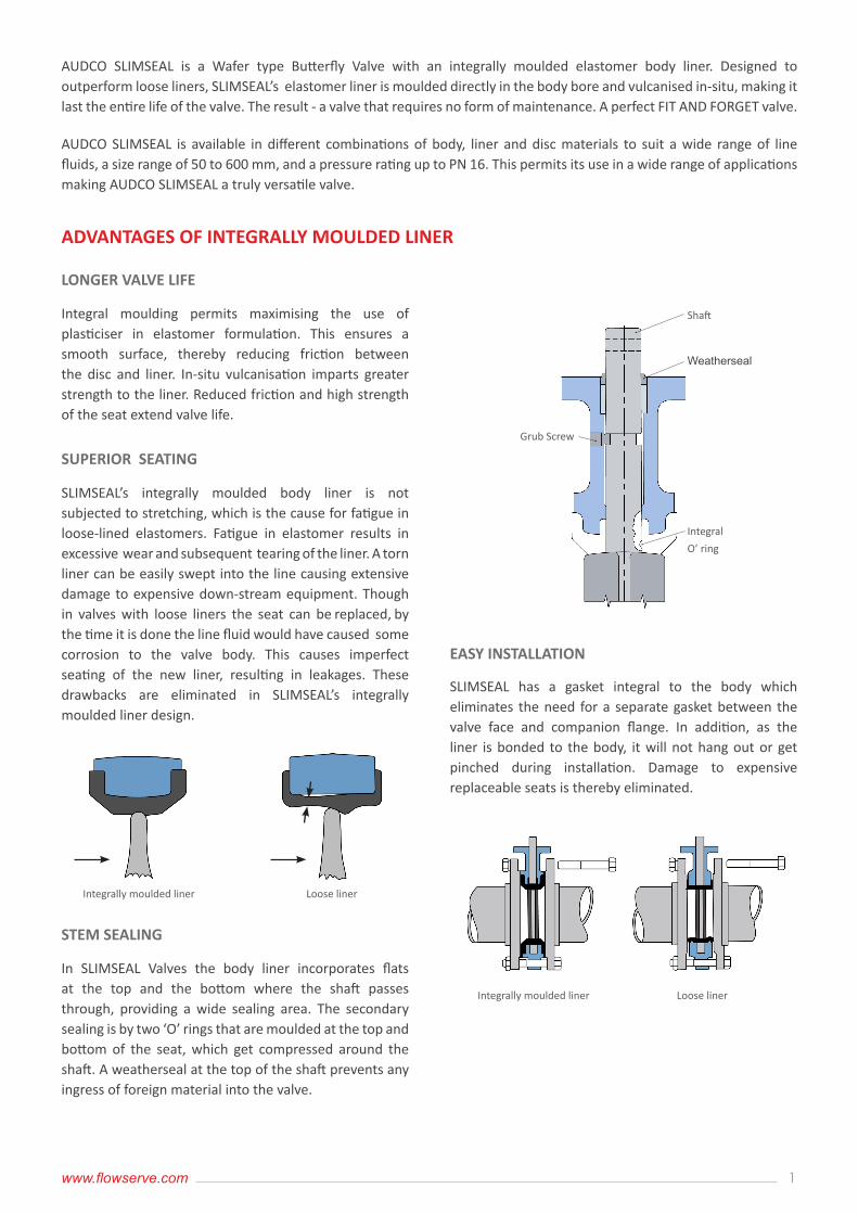
In SLIMSEAL Valves the body liner incorporates flats at the top and the bottom where the shaft passes through, providing a wide sealing area. The secondary sealing is by two ‘O’ rings that are moulded at the top and bottom of the seat, which get compressed around the shaft. A weatherseal at the top of the shaft prevents any ingress of foreign material into the valve.
SLIMSEAL has a gasket integral to the body which eliminates the need for a separate gasket between the valve face and companion flange. In addition, as the liner is bonded to the body, it will not hang out or get pinched during installation. Damage to expensive replaceable seats is thereby eliminated.
ADVANTAGES OF INTEGRALLY MOULDED LINER
LONGER VALVE LIFE
SUPERIOR SEATING
STEM SEALING
EASY INSTALLATION
Integrally moulded liner Loose liner
Integrally moulded liner Loose liner
Shaft
Weatherseal
Grub Screw
Integral
O’ ring
2
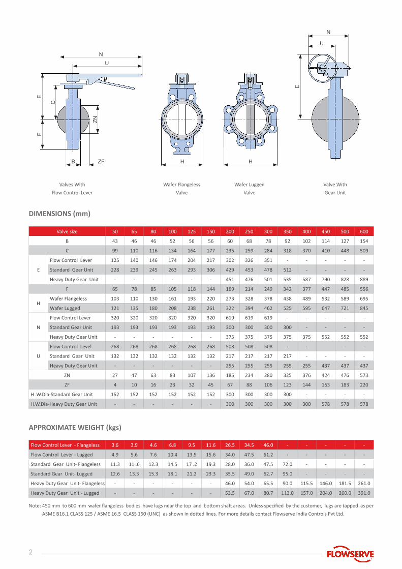
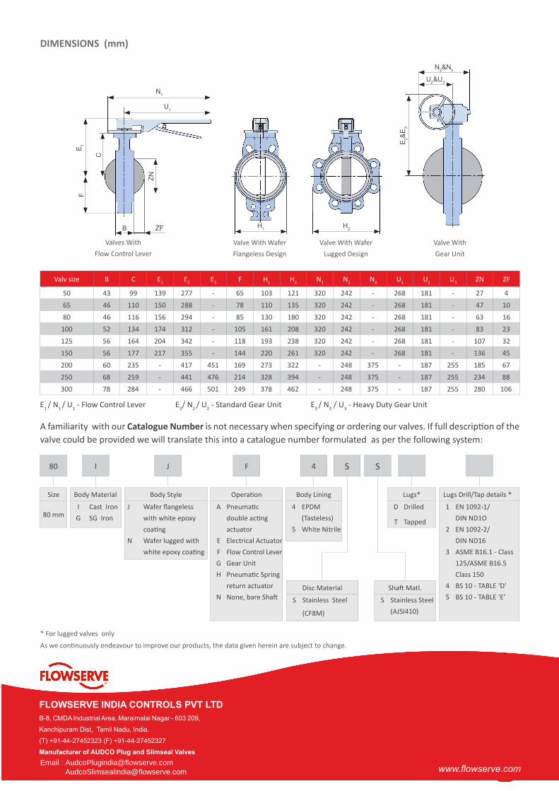
DIMENSIONS (mm)
APPROXIMATE WEIGHT (kgs)
Valve size 50 65 80 100 125 150 200 250 300 350 400 450 500 600
B 43 46 46 52 56 56 60 68 78 92 102 114 127 154
C 99 110 116 134 164 177 235 259 284 318 370 410 448 509
E
Flow Control Lever 125 140 146 174 204 217 302 326 351 - - - - -
Standard Gear Unit 228 239 245 263 293 306 429 453 478 512 - - - -
Heavy Duty Gear Unit - - - - - - 451 476 501 535 587 790 828 889
F 65 78 85 105 118 144 169 214 249 342 377 447 485 556
HWafer Flangeless 103 110 130 161 193 220 273 328 378 438 489 532 589 695
Wafer Lugged 121 135 180 208 238 261 322 394 462 525 595 647 721 845
N
Flow Control Lever 320 320 320 320 320 320 619 619 619 - - - - -
Standard Gear Unit 193 193 193 193 193 193 300 300 300 300 - - - -
Heavy Duty Gear Unit - - - - - - 375 375 375 375 375 552 552 552
U
Flow Control Level 268 268 268 268 268 268 508 508 508 - - - -
Standard Gear Unit 132 132 132 132 132 132 217 217 217 217 - - - -
Heavy Duty Gear Unit - - - - - - 255 255 255 255 255 437 437 437
ZN 27 47 63 83 107 136 185 234 280 325 376 424 476 573
ZF 4 10 16 23 32 45 67 88 106 123 144 163 183 220
H .W.Dia-Standard Gear Unit 152 152 152 152 152 152 300 300 300 300 - - - -
H.W.Dia-Heavy Duty Gear Unit - - - - - - 300 300 300 300 300 578 578 578
Flow Control Lever - Flangeless 3.6 3.9 4.6 6.8 9.5 11.6 26.5 34.5 46.0 - - - - -
Flow Control Lever - Lugged 4.9 5.6 7.6 10.4 13.5 15.6 34.0 47.5 61.2 - - - - -
Standard Gear Unit- Flangeless 11.3 11 .6 12.3 14.5 17 .2 19.3 28.0 36.0 47.5 72.0 - - - -
Standard Gear Unit- Lugged 12.6 13.3 15.3 18.1 21.2 23.3 35.5 49.0 62.7 95.0 - - - -
Heavy Duty Gear Unit- Flangeless - - - - - - 46.0 54.0 65.5 90.0 115.5 146.0 181.5 261.0
Heavy Duty Gear Unit - Lugged - - - - - - 53.5 67.0 80.7 113.0 157.0 204.0 260.0 391.0
N
N
U
B H HZF
Valves With
Flow Control Lever
Wafer Flangeless
Valve
Wafer Lugged
Valve
Valve With
Gear Unit
U
E
ZN
E
F
C
Note: 450 mm to 600 mm wafer flangeless bodies have lugs near the top and bottom shaft areas. Unless specified by the customer, lugs are tapped as per
ASME B16.1 CLASS 125 / ASME 16.5 CLASS 150 (UNC) as shown in dotted lines. For more details contact Flowserve India Controls Pvt Ltd.
3www.flowserve.com
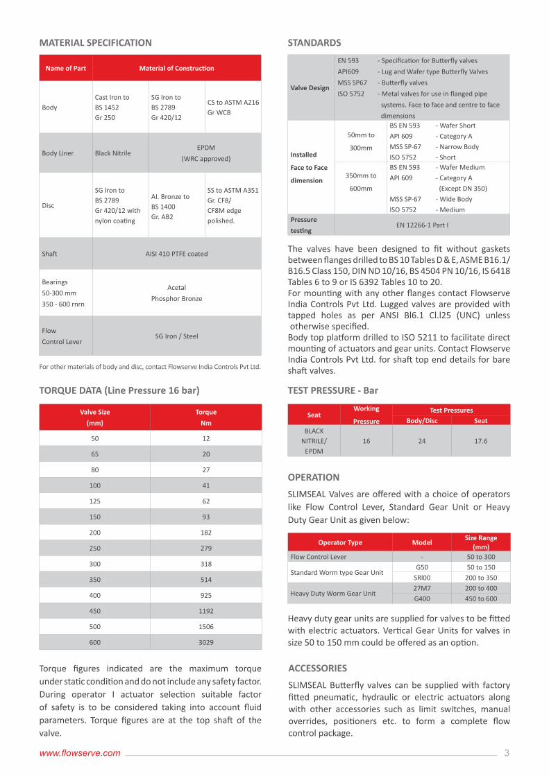
MATERIAL SPECIFICATION STANDARDS
TEST PRESSURE - Bar
OPERATION
ACCESSORIES
TORQUE DATA (Line Pressure 16 bar)
Name of Part Material of Construction
BodyCast Iron toBS 1452Gr 250
SG Iron toBS 2789Gr 420/12
CS to ASTM A216Gr WCB
Body Liner Black NitrileEPDM
(WRC approved)
Disc
SG Iron toBS 2789Gr 420/12 with nylon coating
AI. Bronze toBS 1400Gr. AB2
SS to ASTM A351 Gr. CF8/CF8M edge polished.
Shaft AISI 410 PTFE coated
Bearings
50-300 mm
350 - 600 rnrn
Acetal
Phosphor Bronze
Flow
Control LeverSG Iron / Steel
Valve Design
EN 593
API609
MSS SP67
ISO 5752
- Specification for Butterfly valves
- Lug and Wafer type Butterfly Valves
- Butterfly valves
- Metal valves for use in flanged pipe
systems. Face to face and centre to face
dimensions
Installed
Face to Face
dimension
50mm to
300mm
BS EN 593
API 609
MSS SP-67
ISO 5752
- Wafer Short
- Category A
- Narrow Body
- Short
350mm to
600mm
BS EN 593
API 609
MSS SP-67
ISO 5752
- Wafer Medium
- Category A
(Except DN 350)
- Wide Body
- MediumPressure
testingEN 12266-1 Part I
SeatWorking
Pressure
Test PressuresBody/Disc Seat
BLACK NITRILE/
EPDM16 24 17.6
Operator Type ModelSize Range
(mm)Flow Control Lever - 50 to 300
Standard Worm type Gear UnitG50 50 to 150
SRl00 200 to 350
Heavy Duty Worm Gear Unit27M7 200 to 400G400 450 to 600
Valve Size
(mm)
Torque
Nm
50 12
65 20
80 27
100 41
125 62
150 93
200 182
250 279
300 318
350 514
400 925
450 1192
500 1506
600 3029
For other materials of body and disc, contact Flowserve India Controls Pvt Ltd.
Torque figures indicated are the maximum torque under static condition and do not include any safety factor. During operator I actuator selection suitable factor of safety is to be considered taking into account fluid parameters. Torque figures are at the top shaft of the valve.
The valves have been designed to fit without gaskets between flanges drilled to BS 10 Tables D & E, ASME B16.1/B16.5 Class 150, DIN ND 10/16, BS 4504 PN 10/16, IS 6418 Tables 6 to 9 or IS 6392 Tables 10 to 20.For mounting with any other flanges contact Flowserve India Controls Pvt Ltd. Lugged valves are provided with tapped holes as per ANSI Bl6.1 Cl.l25 (UNC) unless otherwise specified.Body top platform drilled to ISO 5211 to facilitate direct mounting of actuators and gear units. Contact Flowserve India Controls Pvt Ltd. for shaft top end details for bare shaft valves.
SLIMSEAL Valves are offered with a choice of operators like Flow Control Lever, Standard Gear Unit or Heavy Duty Gear Unit as given below:
SLIMSEAL Butterfly valves can be supplied with factory fitted pneumatic, hydraulic or electric actuators along with other accessories such as limit switches, manual overrides, positioners etc. to form a complete flow control package.
Heavy duty gear units are supplied for valves to be fitted with electric actuators. Vertical Gear Units for valves in size 50 to 150 mm could be offered as an option.
4
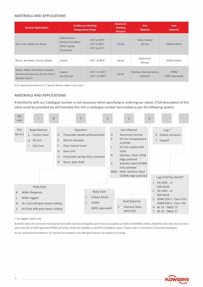
MATERIALS AND APPLICATIONS
MATERIALS AND APPLICATIONS
General ApplicationsContinuous Working
Temperature Range
Maximum Working Pressure
Disc
Material
Seat
Material
Oils, Fuels, Water, Air, Gases
Hydrocarbons
(Except Aromatics)
Other Liquids
Dry Service
- 10°C to 90°C
- 10°C to 80°C
- 10°C to 65°C
16 bar
Nylon Coated
SG Iron # Black Nitrile
Brines, Sea Water, Estuary Water, Liquids - 10°C to 80°C 16 barAluminium
Bronze# Black Nitrile
Steam, Water, Hot Gases, Powders,
Slurries and aqueous slurries of an /
abrasive nature
Liquids
Dry Services
- 10°C to 120°C
- 10°C to 100°C16 bar
Stainless Steel periphery
polished
EPDM
(WRC approved)
# For applications below 5°C, Special Nitrile rubber to be used.
* For lugged valves only
As we continuously endeavour to improve our products, the data given herein are subject to change.
A familiarity with our Catalogue number is not necessary when specifying or ordering our valves. If full description of the valve could be provided we will translate this into a catalogue number formulated as per the following system:
Butterfly valves for corrosive chemical services with internals of Hypalon and Viton are available as AUDCO CHEMSEAL Valves. Butterfly valves for clean services
with internals of WRC approved EPDM and white nitrile are available as AUDCO CLEANSEAL valves. Please refer to Chemseal / Cleanseal Catalogues.
Size
80 mm
Body Material
C
G
I
Carbon Steel
SG Iron
Cast Iron
Lugs *
D
T
Drilled clearance
Tapped
Operation
A
E
F
G
H
N
Pneumatic double acting actuator
Electric Actuator
Flow Control Lever
Gear Unit
Pneumatic spring return actuator
None, bare shaft
Body Style
B
L
Q
Z
Wafer flangeless
Wafer lugged
As L but with grey epoxy coating
As B but with grey epoxy coating
Body Style
2
3
# Black Nitrile
EPDM
(WRC approved)
Shaft Material
S Stainless Steel (AISI 410)
Lugs Drill/Tap details*
1
2
3
45
EN 1092 - 1/ DIN ND10EN 1092 - 2/ DIN ND16ASME B16.1 - Class 125/ASME B16.5 - Class 150BS 10 - TABLE ‘D’BS 10 - TABLE ‘E’
Disc Material
AE
J
R
S
R(M)
Aluminium bronze SG Iron encapsulatedin EPDM SG Iron coated with nylon Stainless Steel (CF8)edge polishedStainless Steel (CF8M)fully polishedR(M) Stainless Steel (CF8M) edge polished
80 mm
I B F J S3
5www.flowserve.com
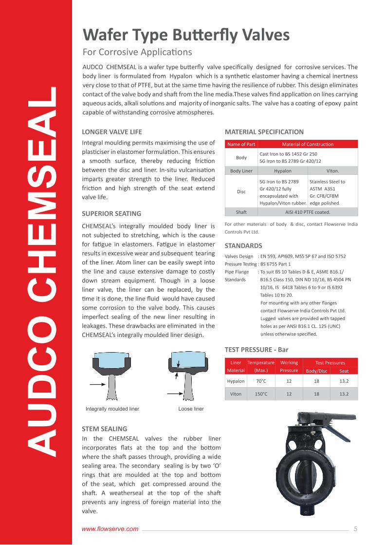
AUDCO CHEMSEAL is a wafer type butterfly valve specifically designed for corrosive services. The body liner is formulated from Hypalon which is a synthetic elastomer having a chemical inertness very close to that of PTFE, but at the same time having the resilience of rubber. This design eliminates contact of the valve body and shaft from the line media.These valves find application on lines carrying aqueous acids, alkali solutions and majority of inorganic salts. The valve has a coating of epoxy paint capable of withstanding corrosive atmospheres.
Integral moulding permits maximising the use of plasticiser in elastomer formulation. This ensures a smooth surface, thereby reducing friction between the disc and liner. In-situ vulcanisation imparts greater strength to the liner. Reduced friction and high strength of the seat extend valve life.
CHEMSEAL’s integrally moulded body liner is not subjected to stretching, which is the cause for fatigue in elastomers. Fatigue in elastomer results in excessive wear and subsequent tearing of the liner. Atom liner can be easily swept into the line and cause extensive damage to costly down stream equipment. Though in a loose liner valve, the liner can be replaced, by the time it is done, the line fluid would have caused some corrosion to the valve body. This causes imperfect sealing of the new liner resulting in leakages. These drawbacks are eliminated in the CHEMSEAL’s integrally moulded liner design.
For other materials of body & disc, contact Flowserve India
Controls Pvt Ltd.
In the CHEMSEAL valves the rubber liner incorporates flats at the top and the bottom where the shaft passes through, providing a wide sealing area. The secondary sealing is by two ‘O’ rings that are moulded at the top and bottom of the seat, which get compressed around the shaft. A weatherseal at the top of the shaft prevents any ingress of foreign material into the valve.
LONGER VALVE LIFE
SUPERIOR SEATING
STEM SEALING
MATERIAL SPECIFICATION
STANDARDS
Wafer Type Butterfly ValvesFor Corrosive Applications
Name of Part Material of Construction
BodyCast Iron to BS 1452 Gr 250SG Iron to BS 2789 Gr 420/12
Body Liner Hypalon Viton.
Disc
SG Iron to BS 2789Gr 420/12 fully encapsulated with Hypalon/Viton rubber.
Stainless Steel toASTM A351Gr. CF8/CF8Medge polished.
Shaft AISI 410 PTFE coated.
Valves Design
Pressure Testing
Pipe Flange
Standards
: EN 593, API609, MSS SP 67 and ISO 5752
: BS 6755 Part 1
: To suit BS 10 Tables D & E, ASME B16.1/
B16.5 Class 150, DIN ND 10/16, BS 4504 PN
10/16, IS 6418 Tables 6 to 9 or IS 6392
Tables 10 to 20.
For mounting with any other flanges
contact Flowserve India Controls Pvt Ltd.
Lugged valves are provided with tapped
holes as per ANSI B16.1 CL. 125 (UNC)
unless otherwise specified.
TEST PRESSURE - Bar
Liner
Material
Temperature
(Max.)
Working
Pressure
Test Pressures
Body/Disc Seat
Hypalon 70°C 12 18 13.2
Viton 150°C 12 18 13.2
AU
DC
O C
HEM
SEA
L
Integrally moulded liner Loose liner
6
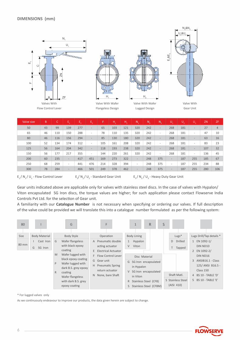
Valve size B C E1 E2 E3 F H1 H2 N1 N2 N3 U1 U2 U3 ZN ZF
50 43 99 139 277 - 65 103 121 320 242 - 268 181 - 27 4
65 46 110 150 288 - 78 110 135 320 242 - 268 181 - 47 10
80 46 116 156 294 - 85 130 180 320 242 - 268 181 - 63 16
100 52 134 174 312 - 105 161 208 320 242 - 268 181 - 83 23
125 56 164 204 342 - 118 193 238 320 242 - 268 181 - 107 32
150 56 177 217 355 - 144 220 261 320 242 - 268 181 - 136 45
200 60 235 - 417 451 169 273 322 - 248 375 - 187 255 185 67
250 68 259 - 441 476 214 328 394 - 248 375 - 187 255 234 88
300 78 284 - 466 501 249 378 462 - 248 375 - 187 255 280 106
E1 / N1 / U1 - Flow Control Lever E2/ N2 / U2 - Standard Gear Unit E3 / N3 / U3 - Heavy Duty Gear Unit
Gear units indicated above are applicable only for valves with stainless steel discs. In the case of valves with Hypalon/Viton encapsulated SG Iron discs, the torque values are higher; for such application please contact Flowserve India Controls Pvt Ltd. for the selection of Gear unit.A familiarity with our Catalogue Number is not necessary when specifying or ordering our valves. If full description of the valve could be provided we will translate this into a catalogue number formulated as per the following system:
As we continuously endeavour to improve our products, the data given herein are subject to change.
DIMENSIONS (mm)
N1
N2&N3
U2&U3
B H1 H2ZF
Valves With
Flow Control Lever
Valve With Wafer
Flangeless Design
Valve With Wafer
Lugged Design
Valve With
Gear Unit
U1
E1
ZN
E2&
E3
F
C
* For lugged valves only
80 I G F 1
Size
80 mm
Body Material
I
G
Cast Iron
SG Iron
Body Lining
1
V
Hypalon
Viton
Lugs*
D
T
Drilled
Tapped
Body Style
G
M
P
R
Wafer flangeless with black epoxy coatingWafer lugged with black epoxy coatingWafer lugged with dark B.S. grey epoxy coatingWafer flangeless with dark B.S. grey epoxy coating
Operation
A
E
F
G
H
N
Pneumatic double
acting actuator
Electrical Actuator
Flow Control Lever
Gear unit
Pneumatic Spring
return actuator
None, bare Shaft
Disc Material
G
V
R
S
SG Iron encapsulated
in Hypalon
SG Iron encapsulated
in Viton
Stainless Steel (CF8)
Stainless Steel (CF8M)
Shaft Matl.
S Stainless Steel
(AISI 410)
Lugs Drill/Tap details *
1
2
3
4
5
EN 1092-1/
DIN ND10
EN 1092-2/
DIN ND16
ANSIB16.1 - Class
125/ ANSI B16.5 -
Class 150
BS 10 - TABLE ‘D’
BS 10 - TABLE ‘E’
R S
7www.flowserve.com
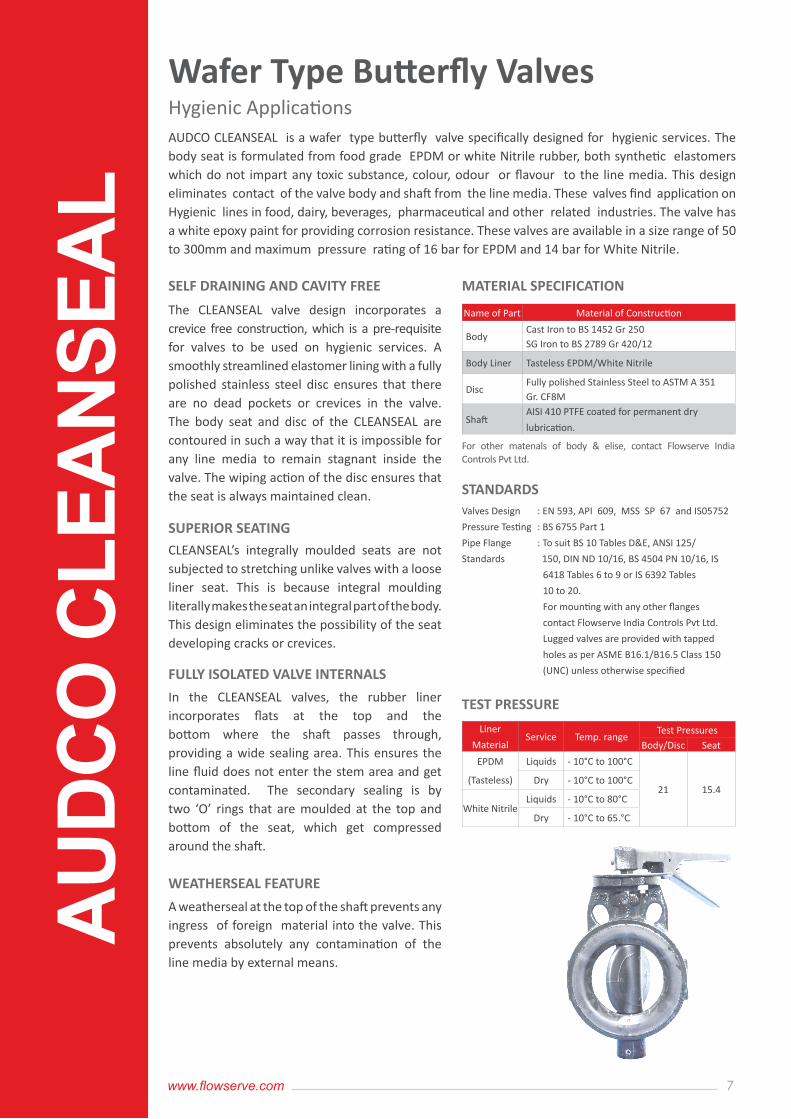
AUDCO CLEANSEAL is a wafer type butterfly valve specifically designed for hygienic services. The body seat is formulated from food grade EPDM or white Nitrile rubber, both synthetic elastomers which do not impart any toxic substance, colour, odour or flavour to the line media. This design eliminates contact of the valve body and shaft from the line media. These valves find application on Hygienic lines in food, dairy, beverages, pharmaceutical and other related industries. The valve has a white epoxy paint for providing corrosion resistance. These valves are available in a size range of 50 to 300mm and maximum pressure rating of 16 bar for EPDM and 14 bar for White Nitrile.
The CLEANSEAL valve design incorporates a crevice free construction, which is a pre-requisite for valves to be used on hygienic services. A smoothly streamlined elastomer lining with a fully polished stainless steel disc ensures that there are no dead pockets or crevices in the valve. The body seat and disc of the CLEANSEAL are contoured in such a way that it is impossible for any line media to remain stagnant inside the valve. The wiping action of the disc ensures that the seat is always maintained clean.
CLEANSEAL’s integrally moulded seats are not subjected to stretching unlike valves with a loose liner seat. This is because integral moulding literally makes the seat an integral part of the body. This design eliminates the possibility of the seat developing cracks or crevices.
For other matenals of body & elise, contact Flowserve India Controls Pvt Ltd.
In the CLEANSEAL valves, the rubber liner incorporates flats at the top and the bottom where the shaft passes through, providing a wide sealing area. This ensures the line fluid does not enter the stem area and get contaminated. The secondary sealing is by two ‘O’ rings that are moulded at the top and bottom of the seat, which get compressed around the shaft.
A weatherseal at the top of the shaft prevents any ingress of foreign material into the valve. This prevents absolutely any contamination of the line media by external means.
SELF DRAINING AND CAVITY FREE
SUPERIOR SEATING
FULLY ISOLATED VALVE INTERNALS
WEATHERSEAL FEATURE
MATERIAL SPECIFICATION
STANDARDS
Name of Part Material of Construction
BodyCast Iron to BS 1452 Gr 250SG Iron to BS 2789 Gr 420/12
Body Liner Tasteless EPDM/White Nitrile
DiscFully polished Stainless Steel to ASTM A 351 Gr. CF8M
ShaftAISI 410 PTFE coated for permanent dry
lubrication.
Valves Design
Pressure Testing
Pipe Flange
Standards
: EN 593, API 609, MSS SP 67 and IS05752
: BS 6755 Part 1
: To suit BS 10 Tables D&E, ANSI 125/
150, DIN ND 10/16, BS 4504 PN 10/16, IS
6418 Tables 6 to 9 or IS 6392 Tables
10 to 20.
For mounting with any other flanges
contact Flowserve India Controls Pvt Ltd.
Lugged valves are provided with tapped
holes as per ASME B16.1/B16.5 Class 150
(UNC) unless otherwise specified
TEST PRESSURE
Liner
MaterialService Temp. range
Test PressuresBody/Disc Seat
EPDM
(Tasteless)
Liquids - 10°C to 100°C
21 15.4Dry - 10°C to 100°C
White NitrileLiquids - 10°C to 80°C
Dry - 10°C to 65.°C
Wafer Type Butterfly ValvesHygienic ApplicationsA
UD
CO
CLE
AN
SEA
L
8
A familiarity with our Catalogue Number is not necessary when specifying or ordering our valves. If full description of the valve could be provided we will translate this into a catalogue number formulated as per the following system:
80 I J F S S4
Size
80 mm
Body Material
I
G
Cast Iron
SG Iron
Body Lining
4
5
EPDM
(Tasteless)
White Nitrile
Lugs*
D
T
Drilled
Tapped
Disc Material
S Stainless Steel
(CF8M)
Shaft Matl.
S Stainless Steel
(AJSI410)
Body Style
J
N
Wafer flangeless
with white epoxy
coating
Wafer lugged with
white epoxy coating
Operation
A
E
F
G
H
N
Pneumatic
double acting
actuator
Electrical Actuator
Flow Control Lever
Gear Unit
Pneumatic Spring
return actuator
None, bare Shaft
Lugs Drill/Tap details *
1
2
3
4
5
EN 1092-1/
DIN ND1O
EN 1092-2/
DIN ND16
ASME B16.1 - Class
125/ASME B16.5
Class 150
BS 10 - TABLE ‘D’
BS 10 - TABLE ‘E’
As we continuously endeavour to improve our products, the data given herein are subject to change.
* For lugged valves only
DIMENSIONS (mm)
N1
N2&N3
U2&U3
B H1 H2ZF
Valves With
Flow Control Lever
Valve With Wafer
Flangeless Design
Valve With Wafer
Lugged Design
Valve With
Gear Unit
U1
E 1
ZN
E 2&E
3
F
C
Valv size B C E1 E2 E3 F H1 H2 N1 N2 N3 U1 U2 U3 ZN ZF
50 43 99 139 277 - 65 103 121 320 242 - 268 181 - 27 4
65 46 110 150 288 - 78 110 135 320 242 - 268 181 - 47 10
80 46 116 156 294 - 85 130 180 320 242 - 268 181 - 63 16
100 52 134 174 312 - 105 161 208 320 242 - 268 181 - 83 23
125 56 164 204 342 - 118 193 238 320 242 - 268 181 - 107 32
150 56 177 217 355 - 144 220 261 320 242 - 268 181 - 136 45
200 60 235 - 417 451 169 273 322 - 248 375 - 187 255 185 67
250 68 259 - 441 476 214 328 394 - 248 375 - 187 255 234 88
300 78 284 - 466 501 249 378 462 - 248 375 - 187 255 280 106
E1 / N
1 / U
1 - Flow Control Lever E
2/ N
2 / U
2 - Standard Gear Unit E
3 / N
3 / U
3 - Heavy Duty Gear Unit
B-8, CMDA Industrial Area, Maraimalai Nagar - 603 209,
Kanchipuram Dist, Tamil Nadu, India.
(T) +91-44-27452323 (F) +91-44-27452327
Manufacturer of AUDCO Plug and Slimseal Valves
www.flowserve.com
FLOWSERVE INDIA CONTROLS PVT LTD
Email : [email protected]
Related Documents
![Hydrodynamic calculation Butterfly valve (lenticular disc) [EN] calculation Butterfly valve... · Hydrodynamic calculation Butterfly valve (lenticular disc)!=0,262’ (=1,15’ Fig.1](https://static.cupdf.com/doc/110x72/5e4d4893a5620b2b3175568a/hydrodynamic-calculation-butterfly-valve-lenticular-disc-en-calculation-butterfly.jpg)