Welcome message from author
This document is posted to help you gain knowledge. Please leave a comment to let me know what you think about it! Share it to your friends and learn new things together.
Transcript
file:///C|/Documents%20and%20Settings/HP_Owner/My%20Documents/Zip%20bare_essential/BareEssentialsTransmitter.txt
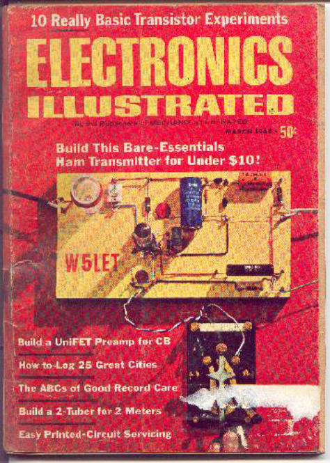
ELECTRONICS ILLUSTRATED MARCH 1968Bare-Essentials Transmitter
By JIM WHITE, W5LET
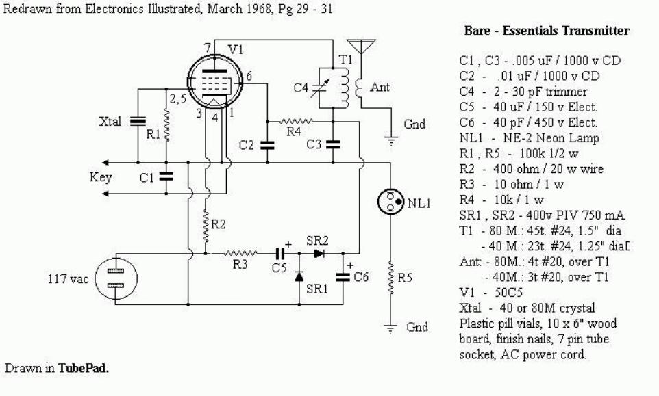
EVERYBODY talks about inflation these days. According to the experts, we're spending too much and driving the price of everything sky high. Washington now threatens us with higher taxes to stop our spree.But for hams on a budget there's a way to have your cake and fight inflation, too. You do spend a little of the green stuff but it won't make much of a dent in your wallet or the national economy. The way out: our Bare-Essentials Transmitter. This little 40- and 80-meter rig takes the prize as the anti-inflationary CW transmitter of the year. You spend only $7 to get it on the air.There's no chassis. The rig is built on a piece of wood--any kind, like the end of an orange crate, will do. And for tie points you use finishing nails. The 5OC5 (or a 5OL6) tube can be salvaged from an old AC/ DC radio. You'll have to spend II¢ for a tube socket but you won't have to buy a socket for the crystal. Its not fancy but it packs a wallop for its price.Used with a mediocre antenna, it has worked stations all over the U.S. When conditions are right and with a good antenna there is no reason why it can't work some real DX. The Circuit: The transmitter consist of a 5OC5 crystal oscillator, which operates on either 40 or 80 meters, Since the 5OC5 has a 50-V filament it uses a 400-ohm 20-watt dropping resistor instead of a filament transformer.The power supply for the plate and screen voltages is a doubler which provides about 350 VDC. Two capacitors, two silicon rectifiers and a 1-watt resistor complete the power supply.
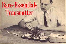
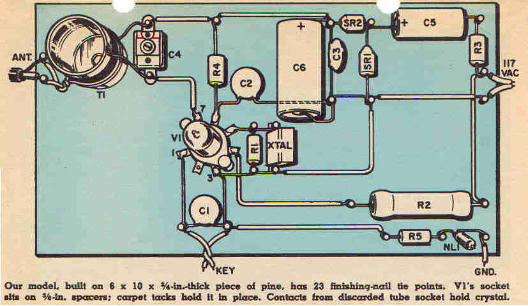
Building The Transmitter: First thing is the chassis, which is simply a 1O x 6 x ¾ -in.-thick piece of wood. Take a close look at the pictorial to see where each part goes. The tube socket is mounted on short spacers so that its lugs clear the wood.
Image 301.jpg and 302.jpg
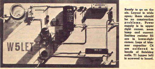
The rest of the parts are soldered to finishing nails in the board. The power-supply components are located in the upper right comer of the board. There is no power switch so the AC leads go directly to the nails.Nails again are used for connecting points for the antenna and for the key. Another nail, located at the lower right of the board is for a ground connection
file:///C|/Documents%20and%20Settings/HP_Owner/My%20Do...nts/Zip%20bare_essential/BareEssentialsTransmitter.txt (1 of 9)8/21/2006 5:29:29 AM
file:///C|/Documents%20and%20Settings/HP_Owner/My%20Documents/Zip%20bare_essential/BareEssentialsTransmitter.txt
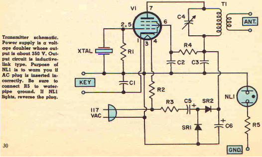
for neon lamp NL1. If the AC plug is in the wrong way, the hot side of the line will be connected to the key. This will mean that 117 V exists from the key to ground, enough to cause a severe shock. However, if the plug is reversed, the ground side of the AC line will be connected to the key circuit and a shock hazard will not exist.
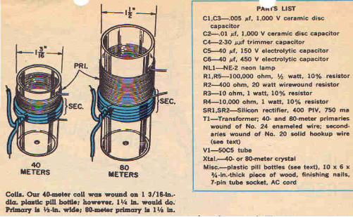
By connecting a water-pipe ground to the nail, the neon lamp will light if the AC plug is in the wrong way. Observe carefully the polarity of the silicon rectifiers and the electrolytics.The coils are wound on plastic pill bottles. The 80 meter coil is wound on a 1 ½ in. dia. x 3 ½ in. long bottle. The 40-meter coil is wound on a 1 3/16 or 1¼ in. dia. x 2 in. long bottle. First drill a small hole in the bottom of each of the bottles for the mounting screw.The plate winding (primary) for the 8O-meter coil is 45 turns of No. 24 enameled wire, closewound. The 40-meter primary is 23 turns of No. 24 enameled wire also closewound. Both secondaries are No. 20 solid hookup wire: the 80 meter is four turns, the 40 meter three turns.Before winding the primaries drill four small holes (two at the top and two at the bottom of the primary winding) in each form. Then thread the ends of the primary wire through these holes.The secondaries are wound over the primary coils and are held in place by twisting the ends together as shown in the coil pictorial(Image 311.jpg)
Image 312.jpg
On The Air: After mounting a coil mount and connect its four leads, then check your work once more. If you're going to work 40, plug a 40-meter crystal into its pin connectors. Plug in the tube, connect an antenna(using 50-ohm coax) to the antenna nails and a key to the key nails. Be sure that you have a water-pipe ground connected to NL1.Now plug in the transmitter. If NL1 glows, reverse the AC plug. Wait about 30 seconds for VI's filament to reach operating temperature and press the key. Quickly adjust C4 until oscillation starts. Oscillation can be determined by listening to a receiver tuned to the crystal frequency. Or hold a neon lamp against the plate transformer. If the transmitter is working the lamp will glow. Adjust C4. When the lamp glows at maximum brilliance, tuning is correct.In loading the transmitter into an antenna some adjustment of T1's secondary may be necessary. Closer coupling can be achieved by moving the coil higher up over the primary winding. An input of about 50 ma at about 350 V (17.5 watts) is about right.Do not operate the transmitter without an antenna because this may cause C4 to break down if the key is held down for an extended period of time.-*-=====================================================From: Gary Johanson <[email protected]>
file:///C|/Documents%20and%20Settings/HP_Owner/My%20Do...nts/Zip%20bare_essential/BareEssentialsTransmitter.txt (2 of 9)8/21/2006 5:29:29 AM
file:///C|/Documents%20and%20Settings/HP_Owner/My%20Documents/Zip%20bare_essential/BareEssentialsTransmitter.txt
To: [email protected]: Tue, 26 Dec 2000 13:47:07 -0500Subject: GB> 50C5 Transmitter
Hi, Gang:Trusting the Holidays are fareing well for you.
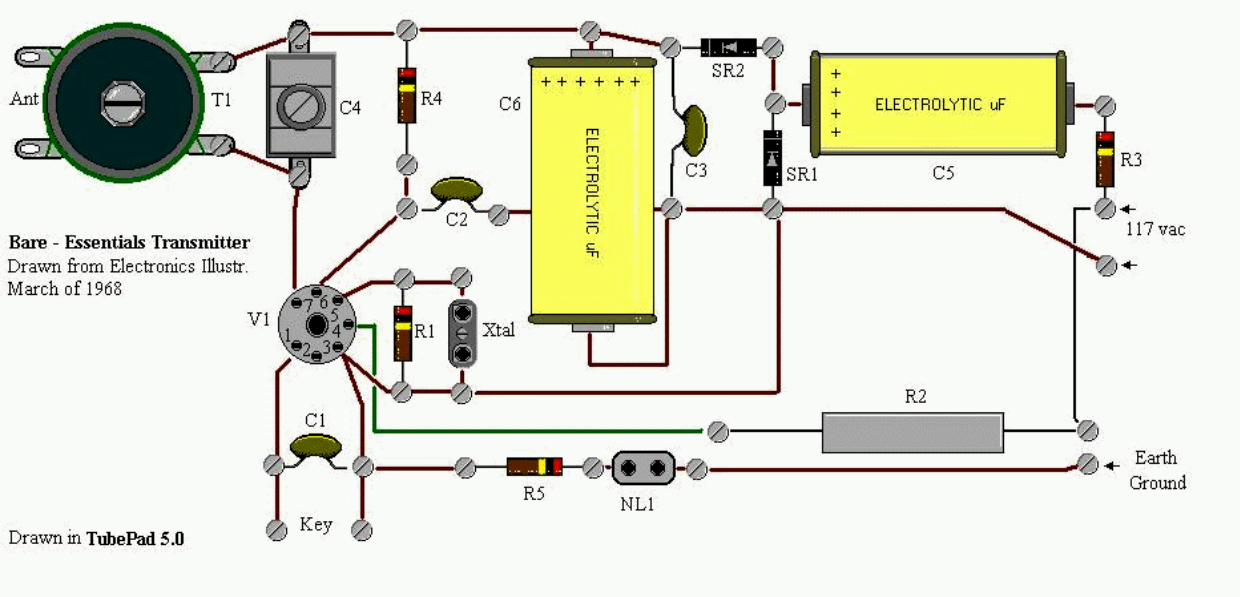
I came across an old article mentioned some yearsago in a nostalgia review of it in the "World of Ideas"column of CQ mag. The author was waxing nostalgicover classic transmitter projects of the 1960's, andmentioned W5LETs article, the "Bare-Essentials"transmitter. I had cut this piece from a March editionof Electronics Illustrated back in 1968 and kept itfolded up in my old Ameco book for years. I pulled itout and re-drew the schematics and cadded up aquick illustration of the layout. It was originally builton a pine board. It is transformerless with a neoncurrent-warning light added for protection. It used a50C5 tube, which was pretty "garden-variety" in theall-american 5-tuber.
If anyone is interested in it, (and happens to havea pile of 50C5s or 50L6s on hand from old table-tops,)let me know. I'll e-mail it direct.
This article is largely word-for-word transcription withsome wise-cracks from yours truly, and a re-editedtuning explanation. But one look at the schematic andyou will recognise it as the old, ubiquitous one-tube crystal-cracker, and the text is non-revelational.
It is e-mailable in a zip file, ( or however Juno bundlesthese multi-files) and plays on any .bmp viewerlike Paint (TubePad). Text is in window's on-board Wordpad.
vy 73gary // wd4nka" . . . who forgets the past forfeits the future . . ."=====================================================From: [email protected]: [email protected], [email protected]: Wed, 27 Dec 2000 20:44:52 EST
file:///C|/Documents%20and%20Settings/HP_Owner/My%20Do...nts/Zip%20bare_essential/BareEssentialsTransmitter.txt (3 of 9)8/21/2006 5:29:29 AM
file:///C|/Documents%20and%20Settings/HP_Owner/My%20Documents/Zip%20bare_essential/BareEssentialsTransmitter.txt
Subject: Re: GB> 50C5 Transmitter
I built that rig when the article first was published, and a second time when I had to present a demonstation in one of my electronics classes. Just be careful, obviously, as 350VDC+ is present on those nail tie points! The rig does work and I was able to make some contacts....but don't expect the note to be a '9'.
Good Luck
KA8GEFEmil =====================================================From: Gary G Johanson <[email protected]>To: [email protected]: [email protected]: Thu, 28 Dec 2000 23:53:11 -0500Subject: Re: GB> 50C5 Transmitter
Hi, Emil and gruppe:
I am not surprised that there would be some ripple on the note.I do remember, on that wireless phono oscillator upon whichi began my short pirate carreer, which was also transformerless,using a 35W4 rectifier and, i think, a 50C5 oscillator, had notrace of any line noise or ripple. Of course, it didn't have to buckso much voltage down for the filament, either. Only had to drop30 volts. Not a whole lot of current, either, for 100 mW. I neverknew what IT'S plate voltage was, but i would guess it was 100v.I don't remember 2 caps for a doubler. I think the plates werewired together as a single diode and served as a half-waverectifier.
The thing i thought might be of some unique value is the powersupply's neon hot-line warning light. I know if i ever gotransformerless,that is ONE feature i will be sure to incorporate. I'd still float thechassis and make provision to avoid the metal, but it is nice toknow the thing isn't gonna bite. Maybe.
I have another transmitter project tucked away that is similar tothis one, only using the not-so-garden variety 117L6 . Not an expensivetube yet, but not one found in the good ol' all American 5'er. But, a
file:///C|/Documents%20and%20Settings/HP_Owner/My%20Do...nts/Zip%20bare_essential/BareEssentialsTransmitter.txt (4 of 9)8/21/2006 5:29:29 AM
file:///C|/Documents%20and%20Settings/HP_Owner/My%20Documents/Zip%20bare_essential/BareEssentialsTransmitter.txt
lot easier on the heat i bet. No huge hi-watt dropping resistor forthe filament. Run the filaments in parallel with the B+ with lots ofde-coupling caps and RF chokes and have DC on the filament. Betthere's a lot of interesting arrangements you can make with oneof those tubes.
vy 73gary // wd4nka======================================================From: "Mike Silva" <[email protected]>To: <[email protected]>Date: Thu, 28 Dec 2000 23:47:55 -0800Subject: Re: GB> 50C5 Transmitter
FWIW, the 85V dropped by a 50C5 / 35W4 combination is exactly the effectivevoltage you get by half-wave rectifying the 120V line. The benefit is thelack of heat dropped in a resistor, not to mention that 1N400Xs are a lotcheaper and more available than the proper dropping resistor.
Given the ample cathodes of the 50C5s and 50L6s, two of them would probablydo fine splitting 85V between them in either a MOPA or Jones rig. (Easier,though, to just use a 35C5 or 35L6 osc. in the MOPA)
BTW, you didn't really mean 117L6, did you? Never saw that one, but itwould be kinda nice if it existed!
73,Mike, KK6GM===================================================From: Gary Johanson <[email protected]>To: [email protected]: [email protected]: Fri, 29 Dec 2000 08:05:54 -0500Subject: Re: GB> 50C5 Transmitter
Mike:I downloaded the mail at the clinic, but if it isnt a 117L6, it issomething like that. It is a pentode or tetrode with a 117v filament,and the designation is such ( 117)I need to look it up when i get home tonight.vy 73gary // wd4nka====================================================
file:///C|/Documents%20and%20Settings/HP_Owner/My%20Do...nts/Zip%20bare_essential/BareEssentialsTransmitter.txt (5 of 9)8/21/2006 5:29:29 AM
file:///C|/Documents%20and%20Settings/HP_Owner/My%20Documents/Zip%20bare_essential/BareEssentialsTransmitter.txt
From: [email protected]: [email protected], [email protected]: [email protected]: Fri, 29 Dec 2000 10:27:34 ESTSubject: Re: GB> 50C5 Transmitter
Probably the 117L7GT, one of a small family of octal tubes with 117 volt heaters. They are all rectifier/power pentode dual tubes. I think they were meant for AC-DC phonographs and phono oscillators. 73 de Jim, N2EY ======================================================From: [email protected]: "Mike Silva" <[email protected]>Cc: [email protected]: Fri, 29 Dec 2000 11:19:21 -0500Subject: Re: GB> 50C5 Transmitter
At 11:47 PM 12/28/2000 -0800, Mike Silva wrote:
>BTW, you didn't really mean 117L6, did you? Never saw that one, but it>would be kinda nice if it existed!
> > I have another transmitter project tucked away that is similar to> > this one, only using the not-so-garden variety 117L6 . Not an expensive> > tube yet, but not one found in the good ol' all American 5'er.
Mike:
The tube is probably the 117L7 or 117N7. This is a pentode/diode combo that was a self-contained oscillator (or whatever) and a diode to supply half-wave rectified DC. A number of articles on simple transmitters using this tube appeared post-WW2 in CQ magazine, among others.
The OT who mentored my Amateur Radio beginnings built many of these and I also built some using his guidelines. I used mine on the 1950's era Novice bands. Some variations included two tubes in a Push-Pull xtal oscillator arrangement.
Today it would be more efficient to just use the pentode sections of these tubes and forget about the diode parts. Silicon diodes would be more efficient and plate voltage could be increased even more by voltage doubling. I recall these tubes running well at 350 volts.
file:///C|/Documents%20and%20Settings/HP_Owner/My%20Do...nts/Zip%20bare_essential/BareEssentialsTransmitter.txt (6 of 9)8/21/2006 5:29:29 AM
file:///C|/Documents%20and%20Settings/HP_Owner/My%20Documents/Zip%20bare_essential/BareEssentialsTransmitter.txt
These 117 volt tubes are not real difficult to find, and surprisingly are not too expensive. I suppose that is because there is not much demand for them. I stocked up on a half dozen some years ago anticipating the high cost/unavailability scenario, but it never happened.Have fun.....Perry w8au======================================================From: Gary G Johanson <[email protected]>To: [email protected]: [email protected]: Sat, 30 Dec 2000 01:01:23 -0500Subject: Re: GB> 117 v tubes
On Fri, 29 Dec 2000 11:19:21 -0500 [email protected] writes:> At 11:47 PM 12/28/2000 -0800, Mike Silva wrote:> > Mike:> > The tube is probably the 117L7 or 117N7. This is a pentode/diode combo > that was a self-contained oscillator (or whatever) and a diode to supply > half-wave rectified DC. A number of articles on simple transmitters using > this tube appeared post-WW2 in CQ magazine, among others.
************* Aye, that's the one. I think it's a tetrode section, actually, rather than a pentode section. I thought i had a copy of the article from an early '90s CQ which had this along with some other quickie tubester QRP rigs. I did not photocopy it for the note-folder, but i kept the mag . . . deep in that forbidden trunk in the chamber of horrors. I recall, now, that it did use it's diode section for the power supply. I never built it because of my natural suspicion of transformerless power supplies. Once bit, twice shy.> >snip<
> Today it would be more efficient to just use the pentode sections of these > tubes and forget about the diode parts. Silicon diodes would be more > efficient and plate voltage could be increased even more by voltage > doubling. I recall these tubes running well at 350 volts.
************ agreed. It would also lessen the jumble of connectionsto that poor ol' octal socket. Since the 117L7 is a diode / tetrode, everypin would be utilised. Yow !! That's rough in a small underchassis.>
file:///C|/Documents%20and%20Settings/HP_Owner/My%20Do...nts/Zip%20bare_essential/BareEssentialsTransmitter.txt (7 of 9)8/21/2006 5:29:29 AM
file:///C|/Documents%20and%20Settings/HP_Owner/My%20Documents/Zip%20bare_essential/BareEssentialsTransmitter.txt
> These 117 volt tubes are not real difficult to find, and surprisingly are > not too expensive. I suppose that is because there is not much demand for > them. I stocked up on a half dozen some years ago anticipating the high > cost/unavailability scenario, but it never happened.
****************I recall them being available in quantity from Antique Electronics Supply.> > Have fun.....> > Perry w8au> > vy 73gary // wd4nka===================================================From: "Mike McKean Sr" <[email protected]>To: <[email protected]>, "Gary G Johanson" <[email protected]>Cc: <[email protected]>Date: Sat, 30 Dec 2000 12:13:01 -0500Subject: Re: GB> 117 v tubes
I built a transmitter a while back using the 117 volt tube with the pentodeand diode...made a 40 meter CW osc out of the pentode and the diode becamethe power supply rectifier...main thing is to ensure that the chassis groundis connected to the neutral side of the AC line...it ran great..lit up anumber 47 light bulb very nicely :-)
Mike N3HJQ---------------------------------------------------From: "Brian Carling" <[email protected]>To: [email protected]: Thu, 28 Dec 2000 08:21:32 -0500Subject: Re: GB> 50C5 Transmitter
The 50C5 TX design is available on-line at:http://www.thebizlink.com/am/tech/htm/50c5.htm====================================================
======================================================
====================================================
========================================================
file:///C|/Documents%20and%20Settings/HP_Owner/My%20Do...nts/Zip%20bare_essential/BareEssentialsTransmitter.txt (8 of 9)8/21/2006 5:29:29 AM

file:///C|/Documents%20and%20Settings/HP_Owner/My%20Documents/Zip%20bare_essential/BareEssentialsTransmitter.txt
=======================================================
file:///C|/Documents%20and%20Settings/HP_Owner/My%20Do...nts/Zip%20bare_essential/BareEssentialsTransmitter.txt (9 of 9)8/21/2006 5:29:29 AM
HP_Owner
FT Club Logo
Related Documents