hallenger hallenger hallenger hallenger alve alve alve alve SECTION 3 INDEX DESCRIPTION BULLETIN NO. Cover Page-Manual Actuators and Accessories MA-100 Mechanical Accessories MA-101 Series LH Lever Handles MA-102 Series DG Worm Gear Actuator Selection Chart MA-103 R3 Series DG Worm Gear Actuator Dimension ( Inches ) MA-104 R2 Series DG Worm Gear Actuator Dimension ( Millimeters ) MA-104 MR2 Series MOA Declutchable Manual Override Design/Operation MA-105 Series MOA Declutchable Manual Override Specs/B.O.M. MA-106 R1 Series MOA Declutchable Manual Override Dimension (Inches) MA-107 R2 Series MOA Declutchable Manual Override Dimension (Millimeters) MA-107MR 2

Welcome message from author
This document is posted to help you gain knowledge. Please leave a comment to let me know what you think about it! Share it to your friends and learn new things together.
Transcript

hallengerhallengerhallengerhallenger
alvealvealvealve
SECTION 3 INDEX
DESCRIPTION BULLETIN
NO.
Cover Page-Manual Actuators and Accessories MA-100
Mechanical Accessories MA-101
Series LH Lever Handles MA-102
Series DG Worm Gear Actuator Selection Chart MA-103 R3
Series DG Worm Gear Actuator Dimension ( Inches ) MA-104 R2
Series DG Worm Gear Actuator Dimension ( Millimeters ) MA-104 MR2
Series MOA Declutchable Manual Override Design/Operation MA-105
Series MOA Declutchable Manual Override Specs/B.O.M. MA-106 R1
Series MOA Declutchable Manual Override Dimension (Inches) MA-107 R2
Series MOA Declutchable Manual Override Dimension (Millimeters) MA-107MR 2

MANUAL ACTUATORS
& ACCESSORIES
Bulletin No. MA-100
Lever Handle c/w 10 Position Notch Plate. DG5 Worm Gear
Actuator.
Gear Actuator c/w Valve Position Transmitter Lever Handle c/w Valve
Position Transmitter

MECHANICAL ACCESSORIES
CHAIN WHEELS
M=Master Note: Specify if master is normally S=Slave open or normally closed.
3 Way Linkage Assemblies
Two valves mounted on a tee actuated by a single actuator; gear, pneumatic or electric. Applications: On-Off change over valves for heating and cooling. Modulating for blending or temperature control.
hallengerhallengerhallengerhallenger
alvealvealvealve
Bulletin No. MA-101

Series Valve No. Size
Eff. Lever
Length
Dimensions (in./mm)
A B C D
Weight
Lbs./Kgs.
LH-A 2”-3” 50-80
10.00”
254
10.5” 1.00” 3.00” 1.62” 267 25.4 76 41
2.5
1.1
LH-B 4”-5” 100-125
10.00”
254
10.5” 1.00” 3.00” 1.62” 267 25.4 76 41
2.5
1.1
LH-C 6” 150
10.00”
254
10.5” 1.00” 3.00” 1.62” 267 25.4 76 41
2.5
1.1
LH-D 8” 200
11.00”
279
11.5” 1.00” 4.00” 2.00” 292 25.4 102 50.8
3.5
1.6
LH-E 10”-12” 250-300
13.25”
337
13.75” 1.00” 4.00” 2.00” 349 25.4 102 50.8
5.0
2.3
hallengerhallengerhallengerhallenger
alvealvealvealve
Bulletin No. MA-102
SERIES LH LEVER Selection and Dimensional Information
Note: Challenger Valve Manufacturing recommends gear actuators for valves 8” ( 200 mm ) and
Materials of Construction Handle: Ducticle Iron Trigger: Steel/Plated Spring: Stainless Steel Notch Plate: Steel Plated
Standard Features Unique self locking trigger prevents the handle from falling off when installed upside down. 10 position notch plate padlockable fully open, fully closed or in any of the other 8 positions. Options: Infinite position plate. Valve Position Transmitter.
hallengerhallengerhallengerhallenger
alvealvealvealve
Bulletin No. MA-103R3
Series Valve Size Gear Handwheel Output Torque at 100 Weight
Dia. Lb.(445 N) Rim Pull c/w H.W.
No. in./mm Ratio in./mm in/lbs./N.m Lbs./Kgs.
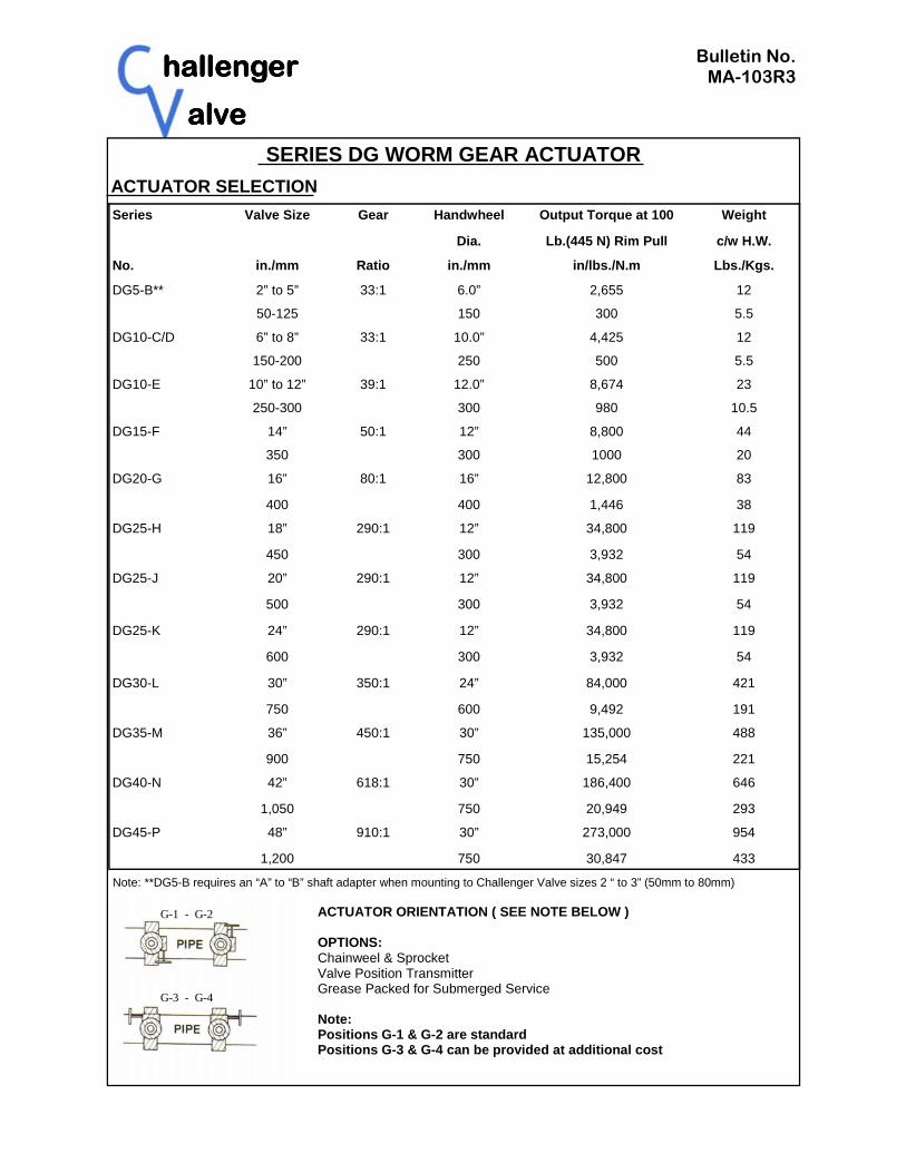
DG5-B** 2” to 5” 33:1 6.0” 2,655 12
50-125 150 300 5.5
DG10-C/D 6” to 8” 33:1 10.0” 4,425 12
150-200 250 500 5.5
DG10-E 10” to 12” 39:1 12.0” 8,674 23
250-300 300 980 10.5
DG15-F 14” 50:1 12” 8,800 44
350 300 1000 20
DG20-G 16” 80:1 16” 12,800 83
400 400 1,446 38
DG25-H 18” 290:1 12” 34,800 119
450 300 3,932 54
DG25-J 20” 290:1 12” 34,800 119
500 300 3,932 54
DG25-K 24” 290:1 12” 34,800 119
600 300 3,932 54
DG30-L 30” 350:1 24” 84,000 421
750 600 9,492 191
DG35-M 36” 450:1 30” 135,000 488
900 750 15,254 221
DG40-N 42” 618:1 30” 186,400 646
1,050 750 20,949 293
DG45-P 48” 910:1 30” 273,000 954
1,200 750 30,847 433
SERIES DG WORM GEAR ACTUATOR ACTUATOR SELECTION
Note: **DG5-B requires an “A” to “B” shaft adapter when mounting to Challenger Valve sizes 2 “ to 3” (50mm to 80mm)
ACTUATOR ORIENTATION ( SEE NOTE BELOW ) OPTIONS: Chainweel & Sprocket Valve Position Transmitter Grease Packed for Submerged Service Note: Positions G-1 & G-2 are standard Positions G-3 & G-4 can be provided at additional cost
G-1 - G-2
G-3 - G-4

hallengerhallengerhallengerhallenger
alvealvealvealve
Bulletin No. MA-104R2
Model Gear A B C D E F G H J Weight
No. Ratio Lbs.
DG5B 33:1 5.55 2.78 0.67 3.13 1.50 6.30 3.50 2.25 5.53 12
DG10-E 39.1 6.50 3.25 0.98 4.00 1.75 7.50 4.25 2.60 6.67 23
DG15 50:1 6.50 3.25 0.74 3.75 1.88 6.25 4.50 3.00 11.75 33
DG20 80:1 10.19 5.10 1.00 4.75 2.38 11.63 6.13 4.25 10.00 71
DG25 290:1 13.25 6.63 0.99 6.00 3.00 12.00 5.00 4.63 12.50 110
DG30 350:1 14.70 7.35 1.00 6.80 3.20 17.50 10.50 7.10 21.40 396
DG35 450:1 17.90 8.95 1.25 7.70 3.50 23.50 12.60 8.90 25.90 458
DG40 618:1 19.70 9.85 1.25 10.00 4.10 28.70 18.90 9.80 27.20 616
DG45 910:1 24.20 12.10 1.50 11.70 5.60 37.80 21.70 12.40 32.20 924
DG10-C/D 33:1 5.55 2.78 0.67 3.13 1.50 6.30 3.50 2.25 5.53 12
ITEM COMPONENT MATERIAL NO. REQ’D
1 Housing Cast Iron 1
2 Shaft Bearing Bronze 2
3 Bearing Washer Steel 2
4 Shaft Plug Steel 1
5 Worm Gear Steel 1
6 Segment Gear Ductile Iron 1
7 Indicator Cap Aluminum 1
8* Cover Bolt Steel 4
9* Stop Adjusting Screw Steel 2
10* Stop Adjusting Nut Steel 2
11 Cover Cast Iron 1
12 Cover Gasket Fibre 1
13 Segment O-Ring BUNA-N 1
14 Input Shaft Seal BUNA-N 1
15 Worm Roll Pin Steel 1
16* Input Shaft Steel 1
17 Handwheel Cast Iron 1
NOTE: HANDWHEELS DG5B TO DG10-E STEEL
*DG5-DG10 Material 304 S.S. OPTIONAL
SERIES DG ACTUATOR DIMENSIONS - INCHES (IMPERIAL)

hallengerhallengerhallengerhallenger
alvealvealvealve
Bulletin No. MA-104MR2
Model Gear A B C D E F G H J Weight
No. Ratio Kgs.
DG5B 33:1 141 70.5 17 74 38.1 160 88.9 57.2 140.5 5.5
DG10 39.1 165 82.5 25 87 44.5 190.5 108 66 169.15 10.5
DG15 50:1 165 83 19 95 48 159 114 76 298 15
DG20 80:1 259 130 25 121 60 295 156 108 254 32
DG25 290:1 337 168 25 152 76 305 127 118 318 50
DG30 350:1 373 187 25 173 81 445 267 180 544 180
DG35 450:1 455 227 32 196 89 597 320 226 658 208
DG40 618:1 500 250 32 254 104 729 480 249 691 280
DG45 910:1 615 307 38 297 142 960 551 315 818 420
DG10-C/D 33:1 141 70.5 17 74 38.1 160 88.9 57.2 140.5 5.5
SERIES DG ACTUATOR DIMENSIONS-MILLIMETRES (METRIC)
ITEM COMPONENT MATERIAL NO. REQ’D
1 Housing Cast Iron 1
2 Shaft Bearing Bronze 2
3 Bearing Washer Steel 2
4 Shaft Plug Steel 1
5 Worm Gear Steel 1
6 Segment Gear Ductile Iron 1
7 Indicator Cap Aluminum 1
8* Cover Bolt Steel 4
9* Stop Adjusting Screw Steel 2
10* Stop Adjusting Nut Steel 2
11 Cover Cast Iron 1
12 Cover Gasket Fibre 1
13 Segment O-Ring BUNA-N 1
14 Input Shaft Seal BUNA-N 1
15 Worm Roll Pin Steel 1
16* Input Shaft Steel 1
17 Handwheel Cast Iron 1
NOTE: HANDWHEELS DG5B TO DG10-E STEEL
*DG5-DG10 Material 304 S.S. OPTIONAL
hallengerhallengerhallengerhallenger
alvealvealvealve
Bulletin No. MA-105
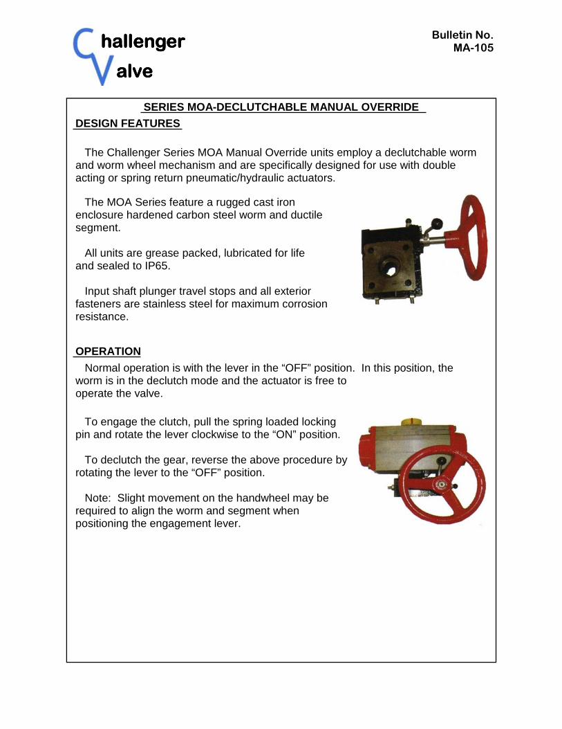
SERIES MOA-DECLUTCHABLE MANUAL OVERRIDE DESIGN FEATURES
The Challenger Series MOA Manual Override units employ a declutchable worm and worm wheel mechanism and are specifically designed for use with double acting or spring return pneumatic/hydraulic actuators.
The MOA Series feature a rugged cast iron enclosure hardened carbon steel worm and ductile segment. All units are grease packed, lubricated for life and sealed to IP65. Input shaft plunger travel stops and all exterior fasteners are stainless steel for maximum corrosion resistance.
OPERATION
Normal operation is with the lever in the “OFF” position. In this position, the worm is in the declutch mode and the actuator is free to operate the valve.
To engage the clutch, pull the spring loaded locking pin and rotate the lever clockwise to the “ON” position. To declutch the gear, reverse the above procedure by rotating the lever to the “OFF” position. Note: Slight movement on the handwheel may be required to align the worm and segment when positioning the engagement lever.

hallengerhallengerhallengerhallenger
alvealvealvealve
Bulletin No. MA-106R1
SERIES GEAR RATIO
TURNS TO
CLOSE
OUTPUT TORQUE IN. LBS
STEM BORE
KEYWAY H.W. DIA.
WEIGHT LBS.
MOA-1 30:1 7.5 2,200 0.875” 0.250” F07 - F07 6” 14
MOA-2
38:1 9.5 6,200 1.250” 0.250” F07/F10 - F10 8” 22
MOA-3 54:1 13.5 11,000 1.75” 0.375” F10 - F10 12” 28
MOA-4 80:1 20 32,000 2.500” 0.500” F14 - F16 16” 96
MOA-5 80:1 20 32,000 3.00” 0.750” F16 - F16
24” 96
MOUNTING PATTERN TO ISO-5211 SPECIFICATION
VALVE-ACTUATOR
SERIES MOA-DECLUTCHABLE MANUAL OVERRIDE SPECIFICATIONS
BILL OF MATERIAL
No. Part Name Qty. Standard Material
1 Quadrant O-Ring 1 Rubber
2 Cam Bridge 1 Carbon Steel AISI 1045, Hardened
3 Quadrant O-Ring 1 Rubber
4 Cam 1 Carbon Steel AISI 1045, Hardened & Galvanized
5 Needle Thrust Bearing 2 AXK-AS
6 Worm 1 Carbon Steel AISI 1045, Hardened
7 Locking Pin 1 316 SS
8 Gasket 1 Rubber
9 Bearing Block 1 Grey Cast Iron ASTM A126 Class B
10 O-Ring 1 Rubber
11 Cam 2 Carbon Steel AISI 1045, Hardened & Galvanized
No. Part Name Qty. Standard Material
12 Lever 1 316 SS
13 Input Shaft 1 316 SS
14 O-Ring 1 Rubber
15 Worm Wheel 1 Ductile Iron ASTM A536 65-45-12
16 Adjusting Screw 2 18-8 SS
17 Gasket 2 Moulded Rubber
18 Lock Nut 2 18-8 SS
19 Protection Cap 2 Moulded Rubber
20 Gear Housing 1 Grey Cast Iron ASTM A126 Class B
21 Gasket 1 Rubber
22 Integral Top Flange 1 Grey Cast Iron ASTM A126 Class B
hallengerhallengerhallengerhallenger
alvealvealvealve
Bulletin No. MA-107R2
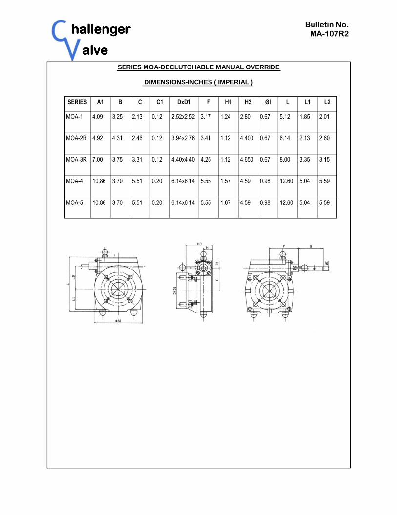
SERIES A1 B C C1 DxD1 F H1 H3 ØI L L1 L2
MOA-1 4.09 3.25 2.13 0.12 2.52x2.52
3.17 1.24 2.80 0.67 5.12 1.85 2.01
MOA-2R 4.92 4.31 2.46 0.12 3.94x2.76 3.41 1.12 4.400
0.67 6.14 2.13 2.60
MOA-3R 7.00 3.75 3.31 0.12 4.40x4.40 4.25 1.12 4.650 0.67
8.00 3.35 3.15
MOA-4 10.86 3.70 5.51 0.20 6.14x6.14 5.55 1.57 4.59 0.98 12.60 5.04 5.59
MOA-5 10.86 3.70 5.51 0.20 6.14x6.14 5.55 1.67 4.59 0.98 12.60 5.04 5.59
SERIES MOA-DECLUTCHABLE MANUAL OVERRIDE
DIMENSIONS-INCHES ( IMPERIAL )

hallengerhallengerhallengerhallenger
alvealvealvealve
Bulletin No. MA-107MR2
SERIES A1 B C C1 DxD1 F H1 H3 ØI L L1 L2
MOA-1 104 82.5 54 3 64x64 80.5 31.5 71 17 130 47 51
MOA-2R 125 109.5 62.5 3 100x70 86.5 28.5 111.8 17 156 54 66
MOA-3R 178 95 84 3 112x112 108 29 118.1 17 203 85 80
MOA-4 276 94 140 5 156x156 141 42.5 116.5 25 320 128 142
MOA-5 276 94 140 5 156x156 141 42.5 116.5 25 320 128 142
SERIES MOA-DECLUTCHABLE MANUAL OVERRIDE
DIMENSIONS-MILLIMETRES ( METRIC )
Related Documents