Max-Planck-Institut für Eisenforschung GmbH Investigation of the texture and microstructure evolution around a nanoindent close to an individual grain boundary. David Mercier 1 ([email protected] ), C. Zambaldi 1 , P. Eisenlohr 2 M. A. Crimp 2 , T. R. Bieler 2 1 Max-Planck-Institut für Eisenforschung, 40237 Düsseldorf, Germany 2 Michigan State University, East Lansing, MI 48824, USA 17 th International Conference on Textures of Materials August 24-29, 2014 | Dresden, Germany Gr. A Gr. B

Gr. A
Jan 07, 2016
Gr. A. Investigation of the texture and microstructure evolution around a nanoindent close to an individual grain boundary . David Mercier 1 ( [email protected] ), C. Zambaldi 1 , P. Eisenlohr 2 M. A. Crimp 2 , T. R. Bieler 2 - PowerPoint PPT Presentation
Welcome message from author
This document is posted to help you gain knowledge. Please leave a comment to let me know what you think about it! Share it to your friends and learn new things together.
Transcript

Max-Planck-Institut für Eisenforschung GmbH
Investigation of the texture and microstructure evolution around a nanoindent close to an individual grain boundary.
David Mercier1 ([email protected]),
C. Zambaldi1, P. Eisenlohr2
M. A. Crimp2, T. R. Bieler2
1Max-Planck-Institut für Eisenforschung, 40237 Düsseldorf, Germany2Michigan State University, East Lansing, MI 48824, USA
17th International Conference on Textures of MaterialsAugust 24-29, 2014 | Dresden, Germany
Gr. A
Gr. B

Plasticity of Single Crystal is well understood. Indentation experiments are often used to characterize
plasticity of single crystal…
2014-08-25 MERCIER David 2
Motivation of this work
Inverse pole figure of pile-up topographies of cp-Ti1
Misorientation maps underneath the indentation at different cross sections, comparison between experimental and
simulation results2
1. Zambaldi C. “Orientation informed nanoindentation of a-titanium: Indentation pileup in hexagonal metals deforming by prismatic slip.”, J. Mater. Res., 2012, 27(1), pp. 356-367.
2. Zaafarani N. “On the origin of deformation-induced rotation patterns below nanoindents.”, Acta Mater., 2008, 56, pp. 31-42.
But, missing element to predict polycrystal mechanics…
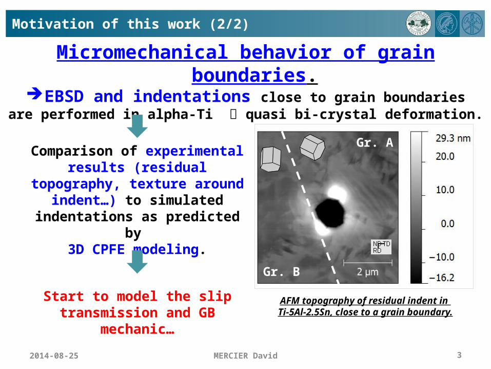
Micromechanical behavior of grain boundaries.EBSD and indentations close to grain boundariesare performed in alpha-Ti quasi bi-crystal deformation.
2014-08-25 MERCIER David 3
AFM topography of residual indent in Ti-5Al-2.5Sn, close to a grain boundary.
Gr. A
Gr. B
Comparison of experimental results (residual topography, texture around indent…) to simulated indentations as
predicted by 3D CPFE modeling.
Start to model the slip transmission and GB
mechanic…
Motivation of this work (2/2)

MERCIER David 4
Strategy Creation of a toolbox
MATLAB Toolbox and Graphical User Interfaces (GUIs)
Slip transmission
model
GB and Bicrystal definition
Crystal Plasticity
2014-08-25

MERCIER David
Bicrystal definition 5 DOF
1. Randle V. “Five-parameter’ analysis of grain boundary networks by electron backscatter diffraction.”, J. Microscopy, 2005, 222, pp. 69-75.
2. Randle V. “A methodology for grain boundary plane assessment by single-section trace analysis.”, Scripta Mater., 2001, 44, pp. 2789-2794
3. Morawiec A., “Orientations and Rotations: Computations in Crystallographic Textures.”, Springer, 2004.
Crystallographic description3
Geometrical description1,2
5
1. Euler angles of grains (12 3) (by EBSD)
Or
2. Misorientation axis / angle[uvw] / w (by EBSD or TEM)
2014-08-25
Trace of the grain boundary (GB)
Crystal 1
Crystal 2
GB
(𝛗𝟏𝛟𝛗𝟐 )𝟏(𝛗𝟏𝛟𝛗𝟐 )𝟐
[𝒖𝒗𝒘 ] /𝝎
nGB
1. GB inclination (b) (by serial polishing or by FIB) and
GB trace (a) (by EBSD )
OrGB normal (nGB)
2. Step between grains after polishing / Rougness (by AFM)
b
a

Crystal Plasticity of alpha-Titanium (hcp)
Large number of dislocation slip and twinning systems.
Slip systems
Twin systems
Pyr. 1st ord. <a>{} < >
Pyr. 1st ord. <c+a>{} <>
Tensile twinning{} < >
Tensile twinning{} < >
Compr. twinning{} < >
Compr. twinning{} < >
Prism. 1st ord. <a>{} < >
Basal <a> {} <>
Pyr. 2nd ord. <c+a>{} <>
Prism. 2nd ord. <a>{} <>
MERCIER David 62014-08-25

MERCIER David
Criteria to predict the slip transmission
m’ factor (from Luster & Morris)21. Livingston J.D . & Chalmers B., “Multiple slip in
bicrystal deformation”, Acta Met. 1957,5, pp. 322-327.
2. Luster J. & Morris M.A., “Compatibility of deformation in two-phase Ti-Al alloys: Dependence on microstructure and orientation relationships.”, Metallurgical and Materials Transactions A, 1995, 26(7), pp. 1745-1756.
3. Marcinkowski M. J. & Tseng W. F., “Dislocation behavior at tilt boundaries of infinite extent.”, Metallurgical Transactions, 1970, 1(12), pp. 3397-3401.
4. Bieler T. R. et al., “The role of heterogeneous deformation on damage nucleation at grain boundaries in single phase metals.”, International Journal of Plasticity, 2009, 25(9), pp. 1655-1683.
coscos' m
7
outinr bbb
N factor (from Livingston & Chalmers)1
Residual Burgers vector3
inoutoutinoutinoutin dndnddnnN **
Schmid Factor, resolved shear stress…4
Outgoing slip Incoming slip
Outgoing slip Incoming slip
2014-08-25

Strain Transfer parameters implemented in the toolbox
MERCIER David 82014-08-25

Outline
Acquisition of EBSD map of the sample
Selection of interesting GBusing the MATLAB Toolbox/GUI
Spherical indentation close to the chosen GBs
Measurement of the topography by AFM and of the lattice rotation by EBSD
Inclination of GB measured by FIB or serial polishing
1st slip transmission analysis viathe MATLAB Toolbox/GUI
Creation of output files for CPFEMusing the MATLAB Toolbox/GUI
3D CPFE modeling
AFM topography of a residual indent
EBSD map
CPFEM displacement result after bicrystal
indentation
Slip transmission model using CPFEM resultsand the MATLAB Toolbox/GUI
Cross sectional view of GB
Exp
erim
ents
Mo
del
ing
MERCIER David 92014-08-25

EBSD on Ti–5Al–2.5Sn (wt%) sample
EBSD orientation map with IPF coloring scheme of Ti–5Al–2.5Sn (wt.%) sample.
MERCIER David 10
The sample exhibited a near- (HCP) microstructure with the body centered cubic (BCC) phase located primarily at α phase grain boundaries1.
Mean grain diameter : (34 ± 16)µm
1. Seal J. R. et al., Mater. Sci. and Eng. A 552, 2012, pp. 61-68.
• Grains number;• Average orientation of each grains Euler angles (phi1, PHI, phi2);• Phase of material;• Average positions and diameters of grains;• GB numbers;• GB trace coordinates ;• Trace length and trace angle.
MATLAB Toolbox/GUI
Outputs from OIM™ Data Analysis
Grain file type 2 and
Reconstructed Boundaries file
Loading and Plot of EBSD data
Loading of EBSD files.
Setting of the coordinate system.
Plot of the GBs segments.
2014-08-25

Introduction to the MATLAB toolbox
MERCIER David 112014-08-25

Isolate a specific GB.
Data transfer from EBSD map into a new window in order to analyze in detail the given bicrystal…
Selection of a specific grain boundary…
MERCIER David 12
Indentation experiments
Gr. A
Gr. B
AFM topography of residual indent in Ti-5Al-2.5Sn, close to a grain boundary with profiles of pile-up surrounding the indent.
2014-08-25
GB
Gr. B Gr. A

MERCIER David 13
Possibility to tune the indenter geometry (tip radius, apex
angle…), sample geometry (GB inclination, sample size…), the mesh parameters (bias, number of elements…)…
Generation of mesh procedure file and material config. file using Python scripts.
CPFE model generation from the GUI
2014-08-25

Few details about CPFE model
Generation of a CPFE model with the MATLAB Toolbox/GUI
References1. S.R. Kalidindi and L. Anand, “An approximate procedure for predicting the evolution of crystallographic texture in bulk deformtion processing of FFC metals.”, Int. J. Mech. Sci. 34(4)
(1992) pp. 309-329.2. A.A. Salem et al., “Strain hardening due to deformation twinning in alpha-titanium: Constitutive relations and crystal-plasticity modeling.”, Acta Materialia 53(12) (2005) pp. 3495-3502.3. X. Wu et al., “Prediction of crystallographic texture evolution and anisotropic stress-strain curves during large plastic strains in high purity alpha-titanium using a taylor-type crystal
plasticity model.”, Acta Materialia, 55(2) (2007) pp. 423-432J.4. Zambaldi C. et al. “Orientation informed nanoindentation of α-titanium: Indentation pileup in hexagonal metals deforming by prismatic slip.”, J. of Mater. Res., 2012, 27(01), pp. 356-367
• The CPFE model used is purely local formulation, and includes only the changes in slip system alignment across the boundary, but no strengthening effect from grain boundaries.
• DAMASK http://damask.mpie.de/
• Flow rule given by Kalidindi’s constitutive model1,2,3
• Only Prismatic 1st order <a>, Basal <a> and Pyramidal 1st order <c+a>
MERCIER David 142014-08-25
Gr. B
Gr. A

MERCIER David 15
CPFEM results (1/3)
•Small discrepancy between experimental and simulated pile-up topographies indicate strain transfer is mainly controlled by geometrical consideration.
Gr. A
Gr. B
AFM topography of residual indent in Ti-5Al-2.5Sn, close to a grain boundary.
Gr. A
Gr. B
Calculated topography from CPFEM of spherical indent close to a GB.
2014-08-25

•The CPFE model with no strengthening effect from grain boundaries seems to predict almost correctly the plasticity transfer.
Gr. B
Gr. AGr. B Gr. A
Local Misorientation from EBSD measurement vs CPFEM results.
EBSDCPFEM
CPFEM results (2/3)
MERCIER David 162014-08-25

Gr. A
Accumulated basal shear
Accumulated prism. 1<a>
shear
Gr. B
Isosurfaces of accumulated shear int the bicrystal obtained by CPFEM.
CPFEM results (3/3)
Slip transfer is based on the geometrical compatibility of the two grains (high m’ value for prism. 1 <a> and basal, low RBV, high LRB…).
MERCIER David 172014-08-25

Advantages of the GUI
MERCIER David 18
•Analysis of all GBs in a map (and color coded results), then selection of interesting ones
•Fast transfer of experimental data into simulation input files : SX indentation BX indentation
•Reduction of possible sources of error in analysis by visualization, standardized workflow and automated data I/O
•Readily extendible to other experiments : Polycrystal tensile test µ-cantilever bending test µ-pillar compression test Straining test and TEM
1. Zhao Z. et al., “Investigation of three-dimensional aspects of grain-scale plastic surface deformation of an aluminum oligocrystal.”, International Journal of Plasticity 24, 2008, pp. 2278-2297.
2. Dehm G. et al., “Plasticity and Fracture at Small Length Scales: from Single Crystals towards Interfaces.”, Workshop on Mechanical Behaviour of Systems – 4, 2013 (India).
3. Shen Z. et al., “Dislocation and grain boundary interactions in metal.”, Acta Metal., 1988, 36(12), pp. 3231-3242.
Cu bi-crystal
Tensile test of Aluminum oligocrystal “dogbone”1.
Straining test and TEM3.
µ-pillar compression test and µ-cantilever bending test 2.
2014-08-25
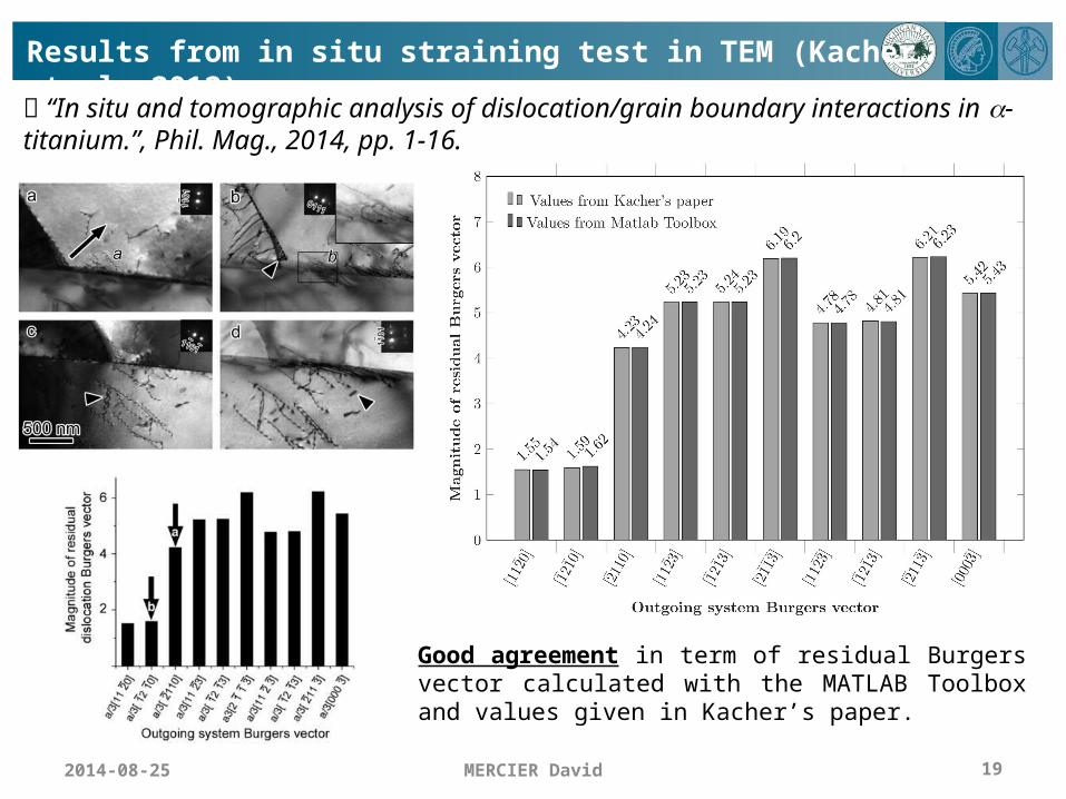
Results from in situ straining test in TEM (Kacher et al. 2012)
MERCIER David 19
“In situ and tomographic analysis of dislocation/grain boundary interactions in a-titanium.”, Phil. Mag., 2014, pp. 1-16.
Good agreement in term of residual Burgers vector calculated with the MATLAB Toolbox and values given in Kacher’s paper.
2014-08-25

Results from polycrystal tensile test (Patriarca et al. 2014)
MERCIER David 20
“Slip transmission in bcc FeCr polycrystal.”, Materials Science and Engineering: A, 2014, 588, pp. 308-317.
Good agreement in term of residual Burgers vector calculated with the MATLAB Toolbox and values given in Patriarca’s paper.
2014-08-25

Conclusion and Outlook
•MATLAB Toolbox / GUI = “Bridge between EBSD and CPFEM” For bcc, fcc and hcp materials and for 1 or 2 phase materials Slip trace analysis Many functions implemented to analyze and to quantify the potential
for slip transmission at GBs Interfaced with Python code to rapidly generate CPFE simulation
input files for indentation experiments Possibility to implement new functions and new CPFE models for
other experiments (µ-cantilever, µ-pillar, straining test…) http://github.com/czambaldi/stabix Proceedings paper on ICOTOM17 conference
• Preliminary results : CPFE model with no strengthening effect from grain boundaries seems to predict almost correctly the plasticity transfer.
•More indentation and 3D EBSD experiments to do…
MERCIER David 212014-08-25
Acknowledgments and Questions
Dr. P. Eisenlohr, Dr. M. Crimp and Y. Su are acknowledged.
Materials World Network grant references NSF: DFG: ZA523/3-1
Thanks for your attention….
Questions ?
MERCIER David 22
2014-08-25
Related Documents