GOON WOLF ~P.C.~ ATTORNEYS AT LAW January 8, 2015 Attorney Melanie Bachman Acting Executive Director Connecticut Siting Council Ten Franklin Square New Britain, CT 06051 JULIE D. KOHLER PLEASE REPLY TO: BCICIQep01"t WRITER~s ~iREc- r oia~: (203) 337-4157 E-Mail Address: [email protected] Re: Notice of Exempt Modification CTI Tower Assets 1, LLC/T-Mobile equipment upgrade Site ID CT11031 B 21 East Main Street, Clinton Dear Attorney Bachman: This office represents T -Mobile Northeast LLC ("T -Mobile") and has been retained to file exempt modification filings with the Connecticut Siting Council on its behalf. In this case, CTI Tower Assets 1, LLC owns the existing lattice telecommunications tower and related facility at 21 East Main Street Connecticut (latitude 41.27894874/longitude 72.5259641). T -Mobile intends to add three (3) antennas and related equipment at this existing telecommunications facility in Clinton ("Clinton Facility"). Please accept this fetter as notification, pursuant to R.C.S.A. § 16-50j-73, of construction which constitutes an exempt modification pursuant to R.C.S.A. § 16 -50j -72(b)(2). In accordance with R.C.S.A. § 16-50j-73, a copy of this letter is being sent to the First Selectman William W. Fritz and the property owner, Storer Communications of Clinton. The existing Clinton Facility consists of an approximately 67.5 foot tall lattice structure.' T -Mobile plans to add three (3) antennas on T -Arms at a centerline of 60 feet. T -Mobile will also install three (3) RRUs (remote radio units) on an existing stairwell wall, install six (6) diplexers, install six (6) TMAs (tower mounted amplifiers), and reuse existing coax cable all within the compound area. T -Mobile will also remove 3G RRUs and two (2) equipment cabinets. See the plans revised to December 12, 2014 attached hereto as Exhibit A. The existing Facility is structurally capable of supporting T -Mobile's proposed modifications, as indicated in the structural analyses dated September 26, 2014 and November 21, 2014, tower modification plans dated September 26, 2014, and the accompanying professional engineer's The online CSC database does not include a Docket or Petition approval for this facility, it does however include a notice of intent captioned EM-T -MOBILE-027-110210 and EM-T -MOBILE -027-141006. 1115 Bxo w STxEST 158 DaFat Hsi.►. AvExua 320 Posr RonD VJEsr 657 Oxarrrc,~ C~rr'►~R Roan P.O. BOX 1821 DnrrBURY Cl' 06810 WeS~t~oRT, GT 06880 ORatac~, CT 06477 BRIDGEPORT, CI' 06601-1821 'ILL: (203) 7922771 1'at: (203) 222-1034 'IY?L: (203) 298-4066 ~L: (203) 368-0211 Fax: (203) 791-8149 FnJc: (203) 227-1373 Fnx: (203) 298-4068 Fnx: (203) 3949901

Welcome message from author
This document is posted to help you gain knowledge. Please leave a comment to let me know what you think about it! Share it to your friends and learn new things together.
Transcript
GOONWOLF~P.C.~ATTORNEYS AT LAW
January 8, 2015
Attorney Melanie BachmanActing Executive DirectorConnecticut Siting CouncilTen Franklin SquareNew Britain, CT 06051
JULIE D. KOHLER
PLEASE REPLY TO: BCICIQep01"t
WRITER~s ~iREc-r oia~: (203) 337-4157E-Mail Address: [email protected]
Re: Notice of Exempt ModificationCTI Tower Assets 1, LLC/T-Mobile equipment upgradeSite ID CT11031 B21 East Main Street, Clinton
Dear Attorney Bachman:
This office represents T-Mobile Northeast LLC ("T-Mobile") and has been retained tofile exempt modification filings with the Connecticut Siting Council on its behalf.
In this case, CTI Tower Assets 1, LLC owns the existing lattice telecommunicationstower and related facility at 21 East Main Street Connecticut (latitude 41.27894874/longitude72.5259641). T-Mobile intends to add three (3) antennas and related equipment at thisexisting telecommunications facility in Clinton ("Clinton Facility"). Please accept this fetter asnotification, pursuant to R.C.S.A. § 16-50j-73, of construction which constitutes an exemptmodification pursuant to R.C.S.A. § 16-50j-72(b)(2). In accordance with R.C.S.A. § 16-50j-73,a copy of this letter is being sent to the First Selectman William W. Fritz and the propertyowner, Storer Communications of Clinton.
The existing Clinton Facility consists of an approximately 67.5 foot tall lattice structure.'T-Mobile plans to add three (3) antennas on T-Arms at a centerline of 60 feet. T-Mobile willalso install three (3) RRUs (remote radio units) on an existing stairwell wall, install six (6)diplexers, install six (6) TMAs (tower mounted amplifiers), and reuse existing coax cable allwithin the compound area. T-Mobile will also remove 3G RRUs and two (2) equipmentcabinets. See the plans revised to December 12, 2014 attached hereto as Exhibit A. Theexisting Facility is structurally capable of supporting T-Mobile's proposed modifications, asindicated in the structural analyses dated September 26, 2014 and November 21, 2014, towermodification plans dated September 26, 2014, and the accompanying professional engineer's
The online CSC database does not include a Docket or Petition approval for this facility, it does however includea notice of intent captioned EM-T-MOBILE-027-110210 and EM-T-MOBILE-027-141006.
1115 Bxo w STxEST 158 DaFat Hsi.►. AvExua 320 Posr RonD VJEsr 657 Oxarrrc,~ C~rr'►~R RoanP.O. BOX 1821 DnrrBURY Cl' 06810 WeS~t~oRT, GT 06880 ORatac~, CT 06477BRIDGEPORT, CI' 06601-1821 'ILL: (203) 7922771 1'at: (203) 222-1034 'IY?L: (203) 298-4066~L: (203) 368-0211 Fax: (203) 791-8149 FnJc: (203) 227-1373 Fnx: (203) 298-4068Fnx: (203) 3949901
COH~NWOLF~PG~ATTONNEYS AT LAW
January 8, 2015Site ID CT11031 BPage 2
letter dated December 19, 2014, all attached hereto as Exhibit B.2
The planned modifications to the Clinton Facility fall squarely within those activitiesexplicitly provided for in R.C.S.A. § 16-50j-72(b)(2).
1 . The proposed modification will not increase the height of the tower. T-Mobile'sreplacement antennas will be installed at the 60 foot level of the approximately 67.5 foot latticetower. The enclosed tower drawing confirms that the proposed modification will not increasethe height of the tower.
2 . The installation of the T-Mobile equipment in the existing compound, as reflectedon pages 2 and 3 of Exhibit B, will not require an extension of the site boundaries. T-Mobile'sproposed equipment will be located entirely within the existing compound area.
3 . The proposed modification to the Facility will not increase the noise levels at theexisting facility by six decibels or more.
4 . The operation of the proposed antennas will not increase the total radiofrequency (RF) power density, measured at the base of the tower, to a level at or above theapplicable standard. According to a Radio Frequency Emissions Analysis Report prepared byEBI dated October 1, 2014 T-Mobile's operations would add 44.72% of the FCC Standard.Therefore, the calculated "worst case" power density for the planned combined operation atthe site including all of the proposed antennas would be 44.72% of the FCC Standard ascalculated for a mixed frequency site as evidenced by the engineering exhibit attached heretoas Exhibit C.
For the foregoing reasons, T-Mobile respectfully submits that the proposed antennasand equipment at the Clinton Facility constitutes an exempt modification under R.C.S.A. § 16-50j-72(b)(2). Upon acknowledgement by the Council of this proposed exempt modification, T-Mobile shall commence construction approximately sixty days from the date of the Council'snotice of acknowledgement.
Sincerely,
J lie D. Kohler, Esq.
Z The Structural Analysis Reports and professional engineer's letter provides for tower modifications to the
Clinton Facility as outlined on Sheet S-1 of the modification plans dated September 26, 2014. These towermodifications will be completed prior to T-Mobile's facility upgrade.

COH~NWOLF~P.Q~AiTORNETS Ai LAW
January 8, 2015Site ID CT11031 BPage 3
cc: Town of Clinton, First Selectman William W. FritzStorer Communications of ClintonCTI Tower Assets 1, LLCSheldon Freincle, NSS

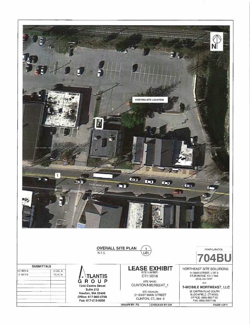
OVERALL SITE PLAN 1 CONFIGURATION
N.T.S. LE1
~~, B U
SUBMITTALS LEASE EXHIBIT NORTHEAST SITE SOLUTIONSLE REVA 07.29.14
SITE NUMBER: 54 MAIN STREET, UNIT3LE REV 0 _ _ 12.12.14 TLANTIS CT11031 B STURBRIDGE, MA 015fi6
GROUP SITE NAME: (506) 434-5237
FOR___ _ 1340 Centre Street CLINTON/I-95/X63/AT_1
T-MOBILE NORTHEAST, LLCSuite 212
---------~-------~--------~--- SITE ADDRESS: 35 GRIFFIN ROAD SOUTHNeuvton, MA 02459
21 EAST MAIN STREET BLOOMFIELD, CT osoo2Office: 617-965-0789
CLINTON, CT, 06413 OFFICE: (Sso) s92a1ooFax: 617-213-5056 F~vc: (aso) ss2aiss
DRAWN BY: FG CHECKED BY:SM PAGEy OF4

14'1'
U
~ ~
~— PAVED PARKING LQT~
~ (E) T-MOBILE 5'-5.6"X 7'-6"CONCRETE PAD /LEASE AREA
(E) COMPOUND ACCESS GATE(E) 6102 CABINET ONCONCRETE PAD
(E) EDGE OFCURB/PAVEMENT ~ ~ ~E 6UILDWG
jE) GRASS AREA
~ /f (E) SHED ROOF STAIRWELL
(E) UTILffY 6ACK BOARD \
f ~ %:
jE) CHAINLINK FENCE AT ~PERIMETEROF COMPOUND 8 ~ `:
1
%. (E) GPS MOUNTED TOj ~E) STAIRWELL WALL
(E) GENERATOR (P) (3) RRUs MOUNTED TO(E) STAIRWELL WALL
Q~w ~ - (E) (12) 7/8 " COAX CABLESH / TO REMAIN
(E) SLIDING GATE a ~
~x a a ,Q i (P) (6) DIPLEXERS
(E) LATTICE TOWER BRACED TO ~ (P) (3) ddB2 TMA
EXISTING HUILDING '~ (P) (3) ddB4 TMA
(E) CHIMNEY ~ ~ '%
(E) ELEC. PANEL &TRANSFORMER~ MiOUNTED TO (E) STAIRWELL WALL
j (E) RAC 35 CABINET TO REMAIN
(P) T-MOBILE ANTENNASON (P) T-ARMSEE PAGE 4
~—EXISTING BUILDING
r
SITE PLANN.T.S. LE2
CONFIGURAi10N
7o~BuSUBMITTALS LEASE EXHIBIT NORTHEAST SITE SOLUTIONS
LE REV A 07.29.14 SITE NUMBER: 54 MAIN STREET, UNIT 3
LE REV 0 ~ 2.12.14 TLANTI S CT11031 B STURBRI~GE, MA 01566
GROUP SITE NAME: (508) 4345237
1340 Centre Street CLINTON/I-95/X63/AT_i FOR
T-MOBILE NORTHEAST, LLCSuite 212
------- SITE ADDReSS: 35 GRIFFIN ROAD SOUTH~_ Newton, MA 02459
21 EAST MAIN STREET BLOOMFIELD, cr osoa2Office: 617-965-0789
CLINTON, CT, 06413 OFFICE: (aso) ss2-~1o0Fax: 617-213-5056 FAX: (860) 692-7159
DRAWN BY: FG CHECKED BY:SM PAGE20F 4
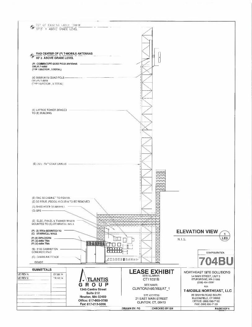
-~.. ~TOP OF Ek~STING LATICE TOWER
`r' b7.5' f ABOVE GRADE LEVEL
~ —RAD CENTER OF (P) T-MOBILE ANTENNAS
'f 60' # ABOVE GRADE LEVEL
(P) COMMSCOPE QUAD POLE ANTENNAON (P) T-ARM(NP 1lSECTOR , 3 TOTAL)
(E) GSMJUMTS QUAD POLEON (P) T-ARM(IYP VSECTOR , 3 TOTAL)
(E) LATTICE TOWER BRACEDTO (E) BUILDING
(E1 (12) 718 "COAX CABLES
(E) RAC 35 CABINET TO REMAIN
(E) 3G RRUS ,PBCO2 ANQ 3515 TO BE REMOVED
(El SHED ROOF STAIRWELL
(E) GPS
(E) ELEC. PANEL &TRANSFORMERMOUNTED TO (E) STAIRWELL WALL
(P) (3) RRUS MOUNTED TO(E) STAIRWELL WALL
(P) (6) DIPLEXERS(Pj (3) ddB2 TMA(Pj (3) ddB4 TMA
(E) 6102 CABINET ONCONCRETE PAD
(E) CNAINLINK FENCE
:1~~ ~,~
~~ ~ .~9~■~~~~.~.
ELEVATION VIEW y
N.T.S. LE3
CONFIGURATION
704 B USUBMITTALS LEASE EXHIBIT NORTHEAST SITE SOLUTIONS
LE REV A 07.29.14 SITE NUMBER: 54 MAIN STREET, UNIT 3LE REV 0 ~ X2.12.14 TLANTIS CT11031 B STURBRIDGE, MA 01566
GROUP SITE NAME: (508) 434-5237
1340 Centre Street CLINTON/I-95/X63/AT_i FOR
Suite 212 T-MOBILE NORTHEAST, LLC
-- -- - — SITe Ao~ReSS: 35 GRIFFIN ROAD SOUTHNewton, MA 02459
21 EAST MAIN STREET B~ooMFIEL~, CT osoozOffice: 617-965-0789
CLINTON, CT, 06413 OFFICE: (860) 692-7100
Fax: 617-213-5056 FAx: (sso) 6s2ai5s
DRAWN BY: FG CHECKED BY:SM PAGE30F4

_€w~
~Qwa
a
14'x'
U
(Z'J j
?~~~~ QELIAD SPOLE~j~LTE
p~'R t1J (1) dd B4 TMA~p~ (1) dd B2 TMA
P~G
(E) GSMJUMTS/LTEQUAD POLE(1) dd 64 TMA(1 ). dd B2 TMA
(E) GSMfUMTS/LTEQUAD POLE(7) ddH4 TMA(7) tldB2 TMA
e ~cHr
1~0
EXISTING ANTENNA CONFIGURATION~~LE4
z`~z~
aQaas
(E)
GSM/UMTSJLT~ ¢~
QUAD POLE(P) LTE 700
QUAD POLE
SUBMITTALS
LE REV A 07.29.14
LE REV 0 12.12.14
(E) GSM IL7MTSj LTE(P) LTE 700 G~UAD POLE
QUAD POLE
00u~ryryo ~9~Nr
Q p'p'D~ (E) GSM/IJ MIS~LTE ~~yY~'qdip' 4~UAD POLE (P) LTE 700 X20,
p~ QUAD POLE
PROPOSED ANTENNA CONFIGURATION~~LE4
CONFIGURATION
704BU
. TLANTISG R O U P1340 Centre Street
Suite 212Newton, MA 02459
Office: 617-965-0789Fax:617-213-5056
LEASE EXHIBITSITE NUMBER:
CT11031 B
SITE NAME:
CLI NTO N/1-95/X63/AT_1
SITE ADDRESS:
21 EAST MAIN STREETCLINTON, CT, 06413
DRAWN BY: FG CHECKED BY:SM
NORTHEAST SITE SOLUTIONS54 MAIN STREET, UNIT 3STURBRIDGE, MA 01566
(508) 434-5237 ~i
FOR
T-MOBILE NORTHEAST, LLC35 GRIFFIN ROAD SOUTHBLOOMFIELD, GT 06002OFFICE: (860) 692-7100FAX: (860) 692-7159
PAGEAOF4

FDH
FDH Engineering, Inc., 6521 Meridien Drive Raleigh, NC 27616, Ph. 919.755.1012
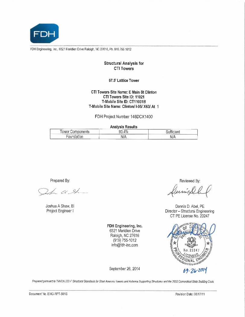
Structural Analysis forCTI Towers
67.5' Lattice Tower
CTI Towers Site Name: E Main St ClintonCTI Towers Site ID: 11021T-Mobile Site ID: CT11031 B
T-Mobile Site Name: Clinton/ I-951 X631 At 1
FDH Project Number 146DCX1400
Analysis ResultsTower Com onents 93.4% Sufficient
Foundation N/A N/A
Prepared By:
~,,.
Joshua A Shaw, EIProject Engineer
FDH Engineering, Inc.6521 Meridien DriveRaleigh, NC 27616(919) [email protected]
September 26, 2014
Reviewed By:,-
Dennis D. Abel, PEDirector—Structural Engineering
CT PE License No. 23247
~~~~s~, F~6.~37.47~.C''• !
`~i ~`' l~~N`~~0.,
Prepared pursuant to TIA/EIA-222-F Structural Standards for Steel Antenna Towers and Antenna Supporting Structures and the 2005 Connecticut State Building Code
Document No. ENG-RPT-501S Revision Date: 06117/11
ay-z~-z~r~
Structural Analysis ReportCTI Towers
Site ID: 11021September 26, 2014
TABLE OF CONTENTS
EXECUTIVESUMMARY ............................................................................................................................................................3
Conclusions............................................................................................................................................................................ 3
Recommendations.................................................................................................................................................................3
APPURTENANCE LISTING .......................................................................................................................................................4
RESULTS...................................................................................................................................................................................5
GENERAL COMMENTS ............................................................................................................................................................7
LIMITATIONS.............................................................................................................................................................................7
APPENDIX .................................................................................................................................................................................8
~. - — —Document No. ENG-RPT-501S Revision Date: 06/17/11
2

Structural Analysis ReportCTI Towers
Site ID: 11021September 26, 2014
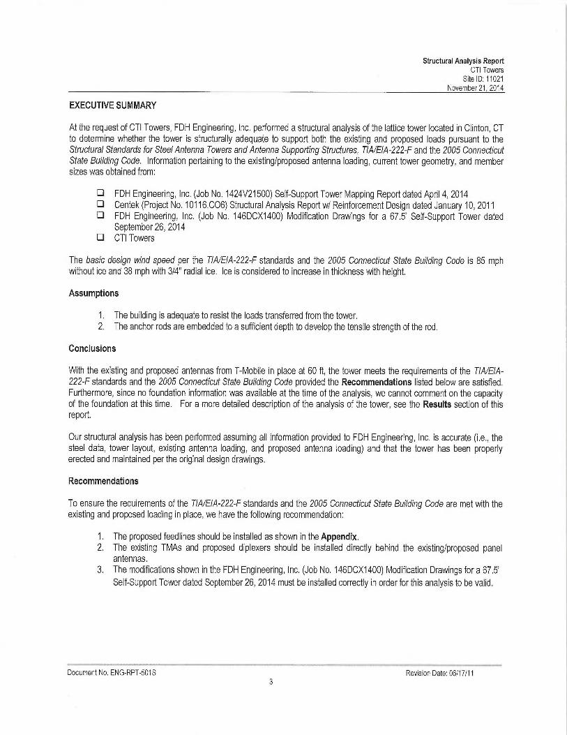
EXECUTIVE SUMMARY
At the request of CTI Towers, FDH Engineering, Inc. performed a structural analysis of the monopole located in Clinton, CTto determine whether the tower is structurally adequate to support both the existing antl proposed loads pursuant to theStructural Standards for Steel Antenna Towers and Antenna Supporting Structures, TIA/EIA-222-F and the 2005 ConnecticutState Building Code. Information pertaining to the existing/proposed antenna loading, current tower geometry, and membersizes was obtained from:
❑ FDH Engineering, Inc. (Job No. 1424V21500) Self-Support Tower Mapping Report dated April 4, 2014❑ Centek (Project No. 10116.006) Structural Analysis Report w/ Reinforcement Design dated January 10, 2011❑ FDH Engineering, Inc. (Job No. 146DCX1400) Modification Drawings fora 67.5' Self-Support Tower dated
September 26, 2014❑ CTI Towers
The basic design wind speed per the TIA/EIA-222-F standards and the 2005 Connecticut State Building Code is 85 mphwithout ice and 38 mph with 3/4" radial ice. Ice is considered to increase in thickness with height.
Assumptions
1. The building is adequate to resist the loads transferred from the tower.2. The anchor rods are embedded to a sufficient depth to develop the tensile strength of the rod.
Conclusions
With the existing and proposed antennas from T-Mobile in place at 60 ft, the tower meets the requirements of the TIA/EIA-222-F standards and the 2005 Connecticut State Building Code provided the Recommendations listed below are satisfied.Furthermore, since no foundation information was available at the time of the analysis, we cannot comment on the capacityof the foundation at this time. For a more detailed description of the analysis of the tower, see the Results section of thisreport.
Our structural analysis has been performed assuming all information provided to FDH Engineering, Inc. is accurate (i,e., thesteel data, tower layout, existing antenna loading, and proposed antenna loading) and that the tower has been properlyerected and maintained per the original design drawings.
Recommendations
To ensure the requirements of the TIA/EIA-222-F standards and the 2005 Connecticut Stafe Building Code are met with theexisting and proposed loading in place, we have the following recommendation:
1. The proposed feedlines should be installed as shown in the Appendix.2. The modifications shown in the FDH Engineering, Inc. (Job No. 146DCX1400) Modification Drawings far a 67.5'
Self-Support Tower dated September 26, 2014 must be installed as specified.
.. _,~__t..~,Document No. ENG-RPT-501S Revision Date: 06/17111

Structural Analysis ReportCTI Towers
Site ID: 11021September 26, 2014
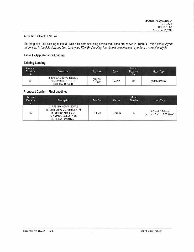
APPURTENANCE LISTING
The proposed and existing antennas with their corresponding cables/coax lines are shown in Table 1. If the actual layoutdetermined in the field deviates from the layout, FDH Engineering, Inc. should be confacted to perform a revised analysis.
Table 1 -Appurtenance Loading
Existing Loading:
Proposed Loading:
Document No. ENG-RPT-501S Revision Date: 06/17/11
Structural Analysis ReportCTI Towers
Site ID: 11021September 26.2014
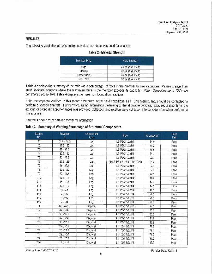
RESULTS
The following yield strength of steel for individual members was used for analysis:
Table 3 displays the summary of the ratio (as a percentage) of force in the member to their capacities. Values greater than100% indicate locations where the maximum force in the member exceeds its capacity. Note: Capacities up to 105% areconsidered acceptable. Table 4 displays the maximum foundation reactions.
If the assumptions outlined in this report differ from actual field conditions, FDH Engineering, Inc. should be contacted toperform a revised analysis. Furthermore, as no information pertaining to the allowable twist and sway requirements for theexisting or proposed appurtenances was provided, deflection and rotation were not taken into consideration when performingthis analysis.
See the Appendix for detailed modeling information
Table 3 - Summary of Working Percentage of Structural Components
.. .~ - .~.~-T1 67.5 - 47.5 Leg L21/2x21/2x1/4 34.9 PassT2 47.5 - 35 Leg L21/2x21/2x1/4 78.2 PassT3 35-32.5 Leg L21/2x21/2x1/4 75.5 PassT4 32.5 - 30 Leg L2112x2 1/2x1 /4 84.7 PassT5 30 - 27.5 Leg L21/2x21/2x114 92.7 PassT6 27.5 - 25 Leg (3) L21/2 x 21/2 x 1 /4 (11201) 34.2 PassT7 25 - 22.5 Leg L21/2x21/2x1/4 93.4 PassT8 22.5 - 20 Leg L2 1/2x21/2x1/4 67.7 PassT9 20 -17.5 Leg L2 112x2 1/2x1/4 42.1 PassT10 17.5-15 Leg L21/2x21/2x1/4 16.2 PassT11 15 -12.5 Leg L21/2x21/2x1/4 17.3 PassT12 12.5 -10 Leg L21/2x21/2x1/4 17.5 PassT13 10-7.5 Leg L21/2x21/2x1/4 19.5 PassT14 7.5 - 5 Leg L2 1/2x2 1/2x1/4 20.5 PassT15 5 - 2.5 Leg L2112x2 1/2x1/4 22.0 PassT16 2.5 - 0 Leg L21/2x21/2x114 28.8 PassT1 67.5 - 47.5 Diagonal L1 1/2x1 1/2x1/4 24.8 PassT2 47.5 - 35 Diagonal L1 1/2x1 1/2x1/4 30.1 PassT3 35 - 32.5 Diagonal L1 1/2x1 1/2x1/4 30.8 PassT4 32.5 - 30 Diagonal L1 112x1 1/2x1/4 31.9 PassT5 30-27.5 Diagonal L11/2x11/2x114 32.9 PassT6 27.5 - 25 Diagonal L1 1/2x1 1/2x1/4 29.7 PassT7 25 - 22.5 Diagonal L1 1/2x1 1/2x1/4 77.1 PassT8 22.5 - 20 Diagonal L1 1/2x1 1/2x1/4 71.3 PassT9 20 -17.5 Diagonal L1 1/2x1 1/2x114 67.2 PassT10 17.5 -15 Diagonal L1 1/2x1 1/2x114 63.8 Pass
_ __,,.~Document No. ENG-RPT-501S Revision Date: 06/17/11
Table 2 -Material Strength
Structural Analysis ReportCTI Towers
Site ID: 11021September 26, 2014
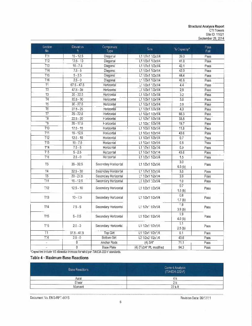
.~ ~ ~.-.~.~ ~-
T11 15 -12.5 Diagonal L1 1/2x1 112x1/4 39.3 PassT12 12.5 -10 Diagonal L1 1/2~c1 1/2x1/4 41.0 PassT13 10-7.5 Diagonal L11/2x1112x1/4 42.1 PassT14 7.5 - 5 Diagonal L1 112x1 112x1/4 43.0 PassT15 5-2.5 Diagonal L1112x11/2x1/4 44.4 PassT16 2.5 - Q Diagonal L1 112x1 112x1/4 45.6 PassT1 67.5 - 47.5 Horizontal L1 112x1 1/2x1/4 4.4 PassT2 47.5-35 Horizontal L11/2x11/2x1/4 2.9 PassT3 35-32.5 Horizontal L1 1/2x1112x1/4 3.2 PassT4 32.5-30 Horizontal L11/2x11/2x1/4 3.5 PassT5 30-27.5 Horizontal L11/2x11/2u1/4 3.9 PassT6 27.5 - 25 Horizontal L1 1/23c1 1/2x1/4 4.3 PassT7 25 - 22.5 Horizontal L1 112x1 1/2x1/4 66.3 PassT8 22.5 - 20 Horizontal L1 1/2x1 1/2x1/4 33.8 PassT9 20 -17.5 Horizontal L1 1/2x1 1/2x1/4 19.7 PassT10 17.5 -15 Horizontal L1 1/2x1 1/2x1/4 11.8 PassT11 15 -12.5 Horizontal L1 1/2x1 1/2x1/4 43.6 PassT12 12.5 -10 Horizontal L1 1/2x1 1/2x1/4 0.7 PassT13 10 - 7.5 Horizontal L1 112x1 112x1/4 0.8 PassT14 7.5-5 Horizontal L1112x11/2x1/4 0.9 PassT15 5 - 2.5 Horizontal L7 1/2x1 1/2x1/4 43.6 PassT16 2.5-0 Horizontal L11/2x11/2x1/4 1.5 Pass
T3 35 - 32.5 Secondary Horizontal L1 1/2x1 1/2x1/4 6 ~"~b~ Pass
T4 32.5 - 30 Secondary Horizontal L1 1/2x1 1/2x1/4 3.5 PassT5 30-27.5 Secondary Horizontal LT 112x1 1/2x1/4 3.9 PassT11 15 -12.5 Secondary Horizontal L1 112x1 1/2x1/4 1.0 Pass
T12 12.5 -10 Secondary Horizontal L1 112x1 1/2~c1/4 15 (b)
Pass
T13 10-7.5 Secondary Horizontal L11/2x11/2x1/4 ~~~~b~ Pass
T14 7.5 - 5 Secondary Horizontal L1 1/2x1 1/2x114 3 9 ~b~ Pass
T15 5 -2.5 Secondary Horizontal L1 1/2x1 1!2x1/4 4:0 (b)
Pass
T16 2.5 - 0 Secondary Horizontal L1 1/2x1 1/2x1/4 2 5 ~b~
Pass
T1 67.5 - 47.5 Top Girt L1 112x1 1/2x1/4 0.1 PassT16 2.5 - 0 Bottom Girt L21/2x21/2x1/4 43.6 Pass- 0 Anchor Rods (4) 3/4" 71.1 Pass- 0 Base Plate (4) 3"x3/4" PL modified 94.3 Pass
Document No. ENG-RPT-501 S Revision Date: 06/17/11
'GapaciUes include 1/3 allowable increase torwintl per IIA/tlA-1L1-F standards.
Table 4 -Maximum Base Reactions
Structural Analysis ReportCTI Towers
Site ID: 11021September 26.2014
This engineering analysis is based upon the theoretical capacity of the structure. It is not a condition assessment of thetower and its foundation. It is the responsibility of CTI Towers to verify that the tower modeled and analyzed is the correctstructure (with accurate antenna loading information) modeled. If there are substantial modifications to be made or theassumptions made in this analysis are not accurate, FDH Engineering, Inc. should be notified immediately to perform arevised analysis.
I~li~il~~_~~[~7~~~
All opinions and conclusions are considered accurate to a reasonable degree of engineering certainty based upon theevidence available at the time of this report. All opinions and conclusions are subject to revision based upon receipt of newor additional/updated information. All services are provided exercising a level of care and diligence equivalent to thestandard and care of our profession. No other warranty or guarantee, expressed or implied, is offered. Our services areconfidential in nature and we will not release this report to any other party without the client's consent. The use of thisengineering work is limited to the express purpose for which it was commissioned and it may not be reused, copied, ordistributed for any other purpose without the written consent of FDH Engineering, Inc.
Document No. ENG-RPT-501S Revision Date: 06/17/11

Structural Analysis ReportCTI Towers
Site ID: 11021September 26, 2014
11~1~
Document No. ENG-RPT-501S Revision Date: 06/17/11
a
x
J
4Z
e
a
N Z ~ tV~ m ~ m aa ~ a ~ H ~
aN
J
J'e
Q
C az
Z
e
r ~~ NJ
J
m
vm y U' ~ 9 N 5~ Y
~ r ~ c@ o = ~ ~ t
'k5 ~ a m~ n z •~ d °~ a ~mN J D D F N~ 2 N ILL ik
67.5 ft
47.5 ft
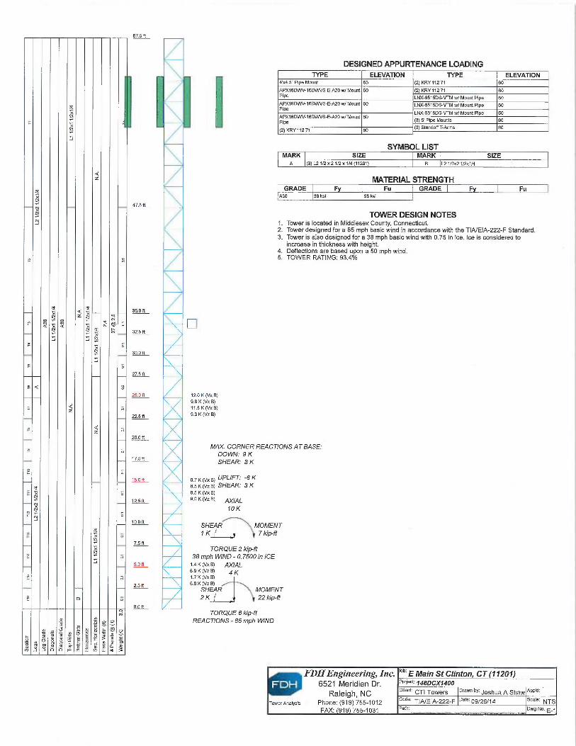
DESIGNED APPURTENANCE LOADINGTYPE ELEVATION TYPE ELEVATION
4X4.5" Pipe Mount 65 (2) KRY 11271 60
APXI6DWV-16DWVSE-A20 w/Moufrt 60 (~KRY 11271 60
P~Pe LNX~515DSVTM w/Mount Pipe 60APX16DV1~16DWVS-E-A20 w/Mount 60 LNX~515DSVTM w/Mount Pipe 60Pipe
APXI6DIMF16DWVS-E-A20 w/Mawrt 60 LNX~515DSVTM w/Mount Pipe 60
Pik (3) 5' Pipe Mourrts 60
(2)KRY 11271 60 (3)Standoff T-Arms 60
SYMBOL LISTMARK SIZE MARK SIZE
A (3) L21/2 x 212 x 114 (11201) B L21/2x21l2x'I/4
MATERIAL STRENGTHGRADE F Fu GRADE F Fu
A36 36 ksi 58 ksi
TOWER DESIGN NOTES1. Tower is located in Middlesex County, Connecticut.2. Tower designed fora 85 mph basic wind in accordance with the TIA/EIA-222-F Standard.3. Tower is also designed fora 38 mph basic wind with 0.75 in ice. Ice is considered to
increase in thickness with height.4. Deflections are based upon a 50 mph wind.5. TOWER RATING: 93.4%
35.0 ft
32.5 ft
30.0 ft
27.5 ft
25.0 ft
225ft
20.0 ft
17.5 ft
15.0 R
12.5 ft
io.on
7.5 R
5.0 ft
2.5 ft
0.0 ft
120 K (Vx B)9.8 K (Vz ~11.5 K (Vx B)9.3 K (Vz B)
MAX. CORNER REACTIONS AT BASE:DOWN: 9 KSHEAR: 3 K
e.7 K (vx s) UPLIFT.' -6 Ke.s K ~v~ e~ SHEAR: 3 K8.5 K (~hc ~9.O K(Vz~ gJ~~AL
10K
SHEAR MOMENT1 K 7 kip-ff
TORQUE 2 kip-ft38 mph WIND - 0.7500 in ICE1.a k (vx e) /~(/ALs.aKNze~ 4K1.7 K (Vx B)6.8 K (Vz B)
SHEAR MOMENT2 K 22 kip-ft
TORQUE 6 kip-ftREACTfONS - 85 mph WIND
FDHEngineering, Inc. °b` E Main St Clinton, CT 71201)w 6521 Meridien Dr. Proie°t: ~asocx~aoo
Raleigh, NC client: CTI Towers Drawn by: Joshua A Shaw APP~d:
TowerMarysis Phone: (919) 755-1012 code: TIA/EIA-222-F oate:09/26/14 scale: NTS
FAX: 919 755-1031 Path: Dwg No. E-~

Feed Line Distribution Chart0' - 67'6"
Round Flat App In Face App Out Face Truss Leg
wc0
dW
FDHEngineering, Inc. °b' E Main St Clinton, CT (11201)■ 6521 Meridien Dr. Pf0Je0' ~asncx~aoo
Raleigh, NCi c~iene CTI Towers Drawn by: ~OSIIUa A SI1flW App'd:
TowerAnalysis Phone: (919) 755-1012 code: TIA/EIA-222-F oate:09/26/14 scale: NTS
FAX: 919 755-1031 Path: Dwg No. E_~
Face A Face B Face C Face D
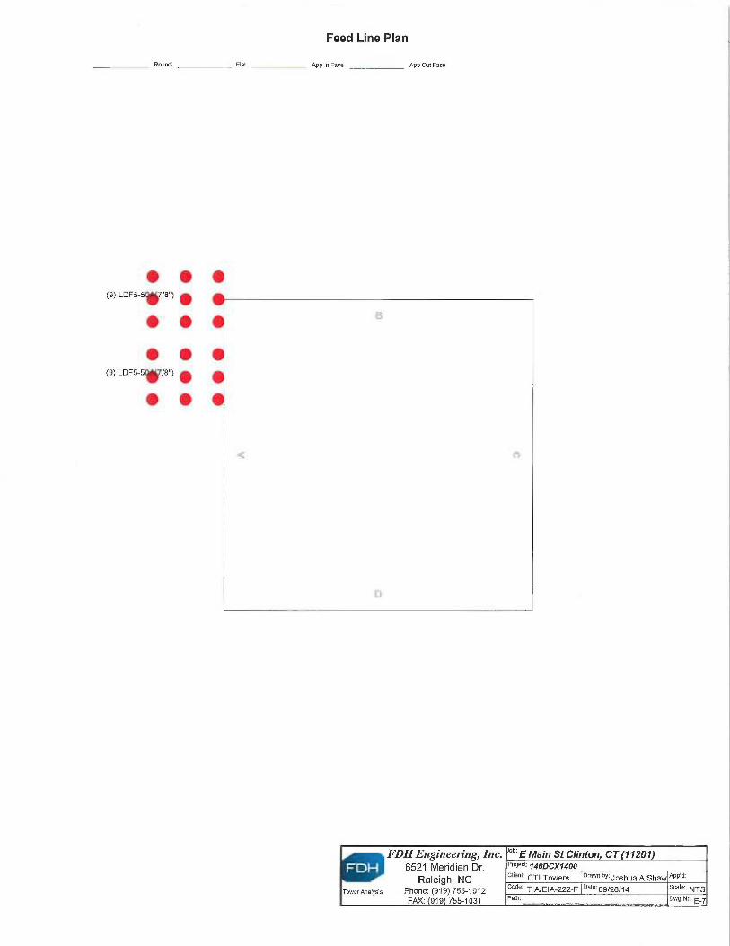
Feed Line Plan
Round
• • •
(9) LDFS-57/8") • •
• • •I~
• • •
• • •
Flat _ _ App In Facc _ App Out Face
FDHEngineering, Inc. °b` E Main St Clinton, CT 11207)~ 6521 Meridien Dr. P~°'B~ ~asocx~aoo
Raleigh, NC ciien~: CTI Towers Drewn 6y: ~OShUB A ShBW App~d:
Towernna~ys~s Phone: (919) 755-1012 code: TIAlEIA-222-F oate:09/26/14 scale: NTS
FAX: 919 755-1031 Path: Dwg No. E_~

1FDH
~.~_ _ _~ _ _ _ ~»u..__ ~ ~ _ ~~FDH Engineering, Inc., 6521 Meridien Drive Raleigh, NC 27616, Ph. 919.755.1012
Structural Analysis forCTI Towers
67.5' Lattice Tower
CTI Towers Site Name: E Main St ClintonCTI Towers Site ID: 11021T-Mobile Site ID: CT11031B
T-Mobile Site Name: Clinton)1.951 X631 At 1
FDH Project Number 146HAZ1400
Anal sis ResultsTower Com onents 98.1 % Sufficient
Foundation N/A N/A
Prepared By: Reviewed By:
J~-~~~~ ~_
Jarel Duncan, EI Bradley R. Newman, PEProject Engineer I Senior Project Engineer
CT PE License No. 29630~ ~111 11 11/~~~'/
FDH Engineering, Inc. ~~`~ of ~~NNF~'~.,
6521 Meridien Drive ` h~`~v~~( R' ,~'~ r~p~ i
Raleigh, NC 27616(919) 755-1012 _ * m ~ [email protected]
'0 X0690
:~~,o ~~CENS~
/'/,~ss~oNA~ ~~621~ ~11~ '-rNovember 21, 2014
Prepared pursuant to TIA/EIA-222-F Structural Standards for SfeelAntenna Towers and Antenna Supporting Structures and the 2005 Connecticut State Building Code
_ _Document No. ENG-RPT-501S Revision Date: 06/17/11
Structural Analysis ReportCTI Towers
Site ID: 11021November 21, 2014
TABLE OF CONTENTS
EXECUTIVE SUMMARY ...........................................
Conclusions ...........................................................
Recommendations ................................................
APPURTENANCE LISTING
......................................................................................................... 3
.........................................................................................................3
......................................................................................................... 3
...........................................................................................
RESULTS...................................................................................................................... .
GENERAL COMMENTS ................................................................................................
LIMITATIONS.................................................................................................................
APPENDIX .....................................................................................................................
.......................................4
.......................................5
.......................................7
.............................. .........7
....................................... 8
Document No. ENG-RPT-501S Revision Date: 06/17/112
Structural Analysis ReportCTI Towers
Site ID: 11021November 21.2014
EXECUTIVE SUMMARY
At the request of CTI Towers, FDH Engineering, Inc. performed a structural analysis of the lattice tower located in Clinton, CTto determine whether the tower is structurally adequate to support both the existing antl proposed loads pursuant to theStructural Standards for Steel Antenna Towers and Antenna Supporting Structures, TIA/EIA-222-F and the 2005 ConnecticutState Building Code. Information pertaining to the existing/proposed antenna loading, current tower geometry, and membersizes was obtained from:
❑ FDH Engineering, Inc. (Job No. 1424V21500) Self-Support Tower Mapping Report dated April 4, 2014❑ Centek (Project No. 10116.006) Structural Analysis Report w/ Reinforcement Design dated January 10, 2011❑ FDH Engineering, Inc. (Job No. 146DCX1400) Modification Drawings fora 67.5' Self-Support Tower dated
September 26, 2014❑ CTI Towers
The basic design wind speed per the TIA/EIA-222-F standards and the 2005 Connecticut State Building Code is 85 mphwithout ice and 38 mph with 3/4" radial ice. Ice is considered to increase in thickness with height.
Assumptions
1. The building is adequate to resist the loads transferred from the tower.2. The anchor rods are embedded to a sufficient depth to develop the tensile strength of the rod.
Conclusions
With the existing and proposed antennas from T-Mobile in place at 60 ft, the tower meets the requirements of the TIA/EIA-222-F standards and the 2005 Connecticut State Building Code provided the Recommendations listed below are satisfied.Furthermore, since no foundation information was available at the time of the analysis, we cannot comment on the capacityof the foundation at this time. For a more detailed description of the analysis of the tower, see the Results section of thisreport.
Our structural analysis has been performed assuming all information provided to FDH Engineering, Inc. is accurate (i.e., thesteel data, tower layout, existing antenna loading, and proposed antenna loading) and that the tower has been properlyerected and maintained per the original design drawings.
Recommendations
To ensure the requirements of the TIA/EIA-222-F standards and the 2005 Connecticut State Building Code are met with theexisting and proposed loading in place, we have the following recommendation:
The proposed feedlines should be installed as shown in the Appendix.The existing TMAs and proposed diplexers should be installed directly behind the existing/proposed panelantennas.The modifications shown in the FDH Engineering, Inc. (Job No. 146DCX1400) Modification Drawings fora 67.5'Self-Support Tower dated September 26, 2014 must be installed correctly in order for this analysis to be valid.
Document No. ENG-RPT-501 S Revision Date: 06/17/11
Structural Analysis ReportCTI Towers
Site ID: 11021November 21, 2014
APPURTENANCE LISTING
The proposed and existing antennas with their corresponding cables/coax lines are shown in Table 1. If the actual layoutdetermined in the field deviates from the layout, FDH Engineering, Inc. should be contacted to perform a revised analysis.
Table 1 -Appurtenance Loading
Existing Loading:
Document No. ENG-RPT-501S Revision Date: 06/17/11
Proposed Carrier— Final Loading:

Structural Analysis ReportCTI Towers
Site ID: 11021November 21, 2014
The following yield strength of steel for individual members was used for analysis:
Table 3 displays the summary of the ratio (as a percentage) of force in the member to their capacities. Values greater than100% indicate locations where the maximum force in the member exceeds its capacity. Note: Capacities up to 105% areconsidered acceptable. Table 4 displays the maximum foundation reactions.
If the assumptions outlined in this report differ from actual field conditions, FDH Engineering, Inc. should be contacted toperform a revised analysis. Furthermore, as no information pertaining to the allowable twist and sway requirements for theexisting or proposed appurtenances was provided, deflection and rotation were not taken into consideration when performingthis analysis.
See the Appendix for detailed modeling information
Table 3 -Summary of Working Percentage of Structural Components
.. ~. ,~.~-T1 67.5 - 47.5 Leg L21/2x21/2x1/4 35.9 PassT2 47.5 - 35 Leg L21/2x21/2x1/4 81.7 PassT3 35 - 32.5 Leg L21/2x21/2x1/4 78.8 PassT4 32.5 - 30 Leg L21/2x21/2x1/4 88.5 PassT5 30-27.5 Leg L21/2x21/2x1/4 96.6 PassT6 27.5 - 25 Leg (3) L21/2 x 2 1/2 x 1/4 (11201) 98.0 PassT7 25 - 22.5 Leg L21/2x21/2x1/4 98.1 PassT8 22.5 - 20 Leg L21 /2x2112x1/4 70.6 PassT9 20 -17.5 Leg L2 1/2x2112x1/4 43.2 PassT10 17.5 -15 Leg L21/2x21/2x1/4 15.4 PassT11 15 -12.5 Leg L21/2x21/2x1/4 17.0 PassT12 12.5 -10 Leg L21/2x21/2x1/4 16.6 PassT13 10-7.5 Leg L21/2x21/2x1/4 18.1 PassT14 7.5-5 Leg L21/2x21/2x1/4 18.9 PassT15 5-2.5 Leg L21/2x21/2x1/4 21.3 PassT16 2.5 - 0 Leg L21/2x21/2x1/4 27.2 PassT1 67.5 - 47.5 Diagonal L1 1/2x1 1/2x1/4 25.4 PassT2 47.5-35 Diagonal L11/2x11/2x1/4 30.4 PassT3 35-32.5 Diagonal L11/2x11/2x1/4 31.3 PassT4 32.5 - 30 Diagonal L1 1/2x1 1/2x1/4 32.3 Pass
T5 30-27.5 Diagonal L11/2x11/2x1/4 33.5 PassT6 27.5-25 Diagonal L11/2x11/2x1/4 30.3 PassT7 25-22.5 Diagonal L11/2x11/2x114 73.9 PassT8 22.5 - 20 Diagonal L1 1/2x1 112x1/4 66.3 Pass
T9 20 -17.5 Diagonal L1 1/2x1 1/2x1/4 65.6 PassT10 17.5 -15 Diagonal L1 1/2x1 1/2x1/4 65.1 Pass
Document No. ENG-RPT-501S Revision Date: 06/17/11
Table 2 -Material Strength

Structural Analysis ReportCTI Towers
Site ID: 11021November 21, 2014
~ ~ . ~....
~-
T11 15 -12.5 Diagonal L1 1/2x1 1/2x1/4 36.5 PassT12 12.5 -10 Diagonal L1 1/2x1 1/2x1/4 38.7 PassT13 10-7.5 Diagonal L11/2x11/2x1/4 39.2 PassT14 7.5-5 Diagonal L11/2x11/2x1/4 40.6 PassT15 5-2.5 Diagonal L11/2x1112x1/4 41.5 PassT16 2.5 - 0 Diagonal L1 1/2x1 1/2x1/4 43.0 PassT1 67.5-47.5 Horizontal L1 1/2x11f2x1/4 4.6 PassT2 47.5-35 Horizontal L11/2x11/2x1/4 3.0 PassT3 35-32.5 Horizontal L11/2x11/2x1/4 3.3 PassT4 32.5 - 30 Horizontal L1 1/2x1 1/2x1/4 3.7 PassT5 30-27.5 Horizontal L11/2x11/2x1/4 4.0 PassT6 27.5 - 25 Horizontal L1 1/2x1 1/2x1/4 4.5 PassT7 25-22.5 Horizontal L71/2x11/2x1/4 68.5 PassT8 22:5 - 20 Horizontal L1 1/2x1 1/2x114 34.5 PassT9 20 -17.5 Horizontal L1 1/2x1 1/2x114 20.2 PassT10 17:5 -15 Horizontal L1 1/2x1 1/2x114 11.7 PassT11 15 -12.5 Horizontal L1 1/2x1 1/2x114 43.6 PassT12 12.5 -10 Horizontal L1 1/2x1 1/2x1/4 0.7 PassT13 10 - 7.5 Horizontal L1 1/2x1 112x1/4 0.8 Pass.T14 7.5-5 Horizontal L11/2x11/2x1/4 0.9 PassT15 5-2.5 Horizontal L11/2x11/2x1/4 43.6 PassT16 2.5-0 Horizontal L1112x11/2x1/4 1.5 Pass
T3 35 - 32.5 Secondary Horizontal L1 1/2x1 1/2x1/4 6 8' ~b~ Pass
T4 32.5 - 30 Secondary Horizontal L1 112x1 1/2x1/4 3.7 PassT5 30 - 27.5 Secondary Horizontal L1 1/2x1 1/2x114 4.0 PassT11 15 -12.5 Secondary Horizontal L1 1/2x1 1/2x1/4 1.0 Pass
T12 12.5 -10 Secondary Horizontal L1 1/2x1 1/2x1/4 1.4 (b)
Pass
T13 10 - 7.5 Secondary Horizontal L1 1/2x1 112x1/4 1 6 (b)
Pass
T14 7.5 - 5 Secondary Horizontal L1 112x1 1/2x1/4 3 9 ~b~ Pass
T15 5 - 2.5 Secondary Horizontal L1 112x1 1/2x1/4 4.0 (b)
Pass
T16 2.5 - 0 Secondary Horizontal L1 1/2x1 1/2x114 2 3 ~b~
Pass
T1 67.5 - 47.5 Top Girt L1 1/2x1 1/2x114 0.1 PassT16 2.5 -0 Bottom Girt L21/2x21/2x1/4 43..6 Pass- 0 Anchor Rods (4) 3/4" 67..8 Pass- 0 Base Plate (4) 3"x3/4" PL modified 90.0 Pass
*Capacities include 1/3 allowable increase for wind per TIA/EIA-222-F standards.
Document No. ENG-RPT-501S Revision Date: 06/17/11
Table 4 - Ma~cimum Base Reactions
Structural Analysis ReportCTI Towers
Site ID: 11021November 21, 2014
GENERAL COMMENTS
This engineering analysis is based upon the theoretical capacity of the structure. It is not a condition assessment of thetower and its foundation. It is the responsibility of CTI Towers to verify that the tower modeled and analyzed is the correctstructure (with accurate antenna loading information) modeled. If there are substantial modifications to be made or theassumptions made in this analysis are not accurate, FDH Engineering, Inc. should be notified immediately to perform arevised analysis.
I~h41~~_~~[~P►~9
All opinions and conclusions are considered accurate to a reasonable degree of engineering certainty based upon theevidence available at the time of this report. All opinions and conclusions are subject to revision based upon receipt of newor atlditionaVupdated information. All services are provided exercising a level of care and diligence equivalent to thestandard and care of our profession. No other warranty or guarantee, expressed or implied, is offered. Our services areconfidential in nature and we will not release this report to any other party without the client's consent. The use of thisengineering work is limited to the express purpose for which it was commissioned and it may not be reused, copied, ordistributed for any other purpose without the written consent of FDH Engineering, Inc.
Document No. ENG-RPT-501S Revision Date: 06/17/11
Structural Analysis ReportCTI Towers
Site ID: 11021November 21, 2014
APPENDIX
Document No. ENG-RPT-501S Revision Date: 06/17/11
v
N
x.N
z
ax
N
ax Z xN N N
Q X Q TC tVeX N
N
N
z
Qz
a
N
N
N
a
N
X
m
c v — — ~ ~ C ~~ ~ y
~ ~ ~ E _ ~ m0 0 0 ~ ~ a >_~ ~ ~ ~ ~
67.5 ft
47.5 ft
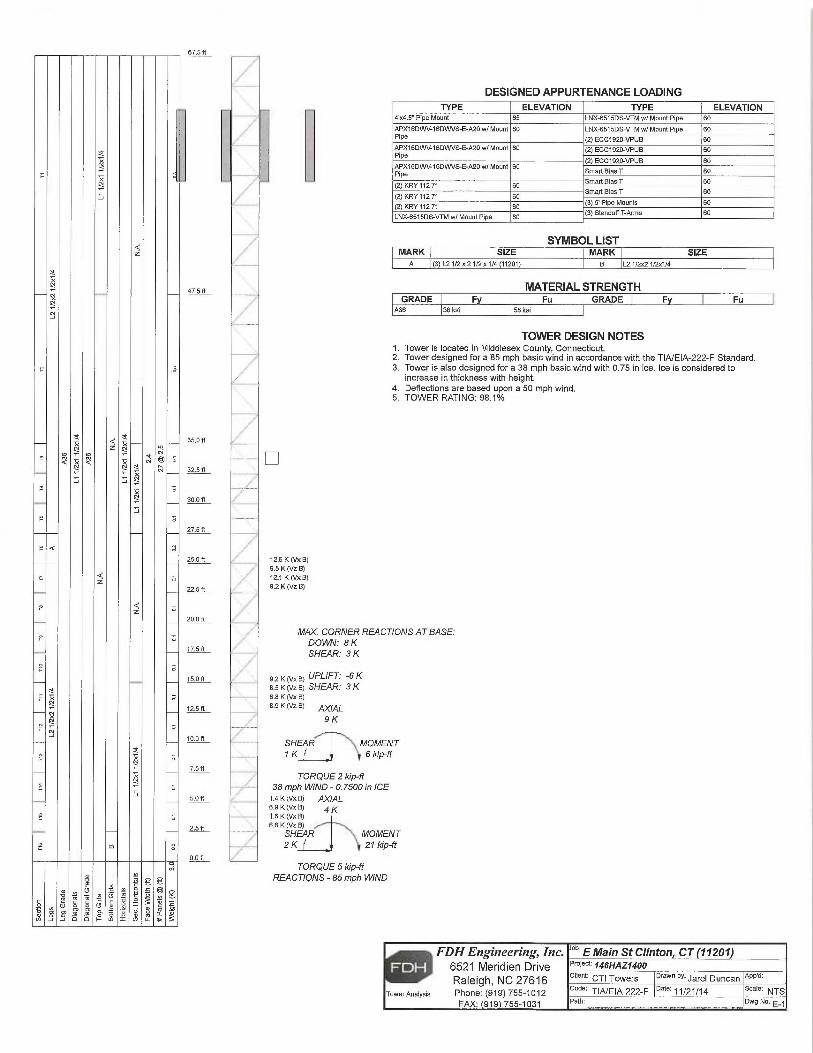
DESIGNED APPURTENANCE LOADINGTYPE ELEVATION TYPE ELEVATION
4'x4.5" Pipe Mount 65 LNX-6515DS-VTM w/Mount Pipe 60
APX16DWV-16DVJVSE-A20 w/Mount 60 LNX-6515DS-VTM w/ Mount Pipe fi0Pipe. (2) ECC1920-VPUB 60APXI6DWV-16DVN/SE-A20 w/Mount 60 (2)ECC1920-VPUB 60Pipe
APX16~WV-16DWVSE-AZO w/Mount 60 (2)ECC1920-VPUB 60
Pipe Smart Bias T 60
(2) FfftY 112 71 60 Smart Bias T 60
(2) KRY 112 71 60 Smart Bias T 60
(2) KRY 112 71 60 (3) 5' Pipe Mounts 60
LNX-6515D5-VTM w/Mount Pipe BD (3)Stantloff T-Arms 60
SYMBOL LISTMARK SIZE MARK SIZE
A (3)L21/2x21/2x1/4 (11201) B L21/2r21/2~c1/4
MATERIAL STRENGTHGRADE F Fu GRADE F Fu
A36 3B ksi 58 ksi
TOWER DESIGN NOTES1. Tower is located in Middlesex County, Connecticut.2. Tower designed fora 85 mph basic wind in accordance with the TIA/EIA-222-F Standard.3. Tower is also designed fora 38 mph basic wind with 0.75 in ice. Ice is considered to
increase in thickness with height.4. Deflections are based upon a 50 mph wind.5. TOWER RATING: 98.1%
35.Oft L_...._._.
32.5 ft
30.0 ft
27:3 ft
25.0 K
22.5 ft
20.0 ft
nse
ts.on
12.5 ft
t o.o a
7.5 ft
5.0 ft
2.5 ft
0.0 ft
12.6K(Vx B)9.5 K (Vz B)12.1 K(Vx B).92 K (Vz B)
MAX. CORNER REACTIONS AT BASE:DOWN: 8 KSHEAR: 3 K
s2 k (vx a) UPLIFT: -6 Kss tc ~v~ a> SHEAR: 3 K8.8 K (Vx B)s.s K ~vz e~ gXIAL
9K
SHEAR MOMENT1 K 6 kip-ft
TORQUE 2 kip-ft38 mph WIND - 0.7500 in ICE1.4 K (Vx B) ,G)(IALs.s K (vz B) 4 K1.6 K (Vx B)6:8 K (Vz B)
SHEAR MOMENT2 K 27 kip-ft
TORQUE 5 kip-ftREACTIONS - 85 mph WIND
FDHEngineering, Inc. °b' E Main St Clinton, CT (17201)■ 6521 Meridien Drive PfOJe ~' 146HAZ1400
R8lelgh, NC 27616 a'e"r CTI Towers Drawnby:~a~el D4f1C2f1 p'PP'd
Tower Anatysis Phone: (919) 755-1012 code: TIA/EIA-222-F Date:. 1/21/14 scale: NTS
FAX: 919 755-1031 Path: Dwg No. E-~
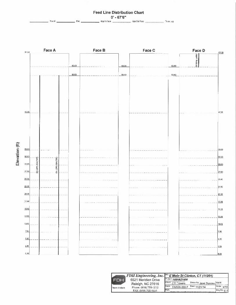
Feed Line Distribution Chart0' - 67'6"
Rountl Flat App In Face __, App Out Face _ _ _ Truss Leg
c0~adw
FDHEngineering, Inc. °b' E Main St Clinton, CT (71201~ 6521 Meridien Drive Project 146HAZ140p
Raleigh, NC 27616 client: CTI Towers prawn dy ~~rel Duncan App~a:
Tower Analysis Phone: (919) 755-1012 code: TIA/EIA-222-F Date: 11/21/14 scale: NTS
FAX: 919 755-1031 Path: Dwg No. E_~
Face A Face B Far_P C Far_P n

THE MODIFICATIONS DEPICTED ON THESE DRAWINGS ARE BASED ON
THE RECOMMENDATIONS OUTLINED IN T
HE STRUCTURAL ANALYSIS
COMPLETED BY FDH ENGINEERING, INC., P
ROJECT NO. 146CNZ1400
DATED SEPTEMBER 9. 2
014.
THIS REPORT WAS BASED ON A SPECIFIC ANTENNA AND COAX
CONFIGURATION PROVIDED BY THE TOWER OWNER. ANY CHANGE TO
THIS INFORMATION MUST BE REVIEWED BY FDH ENGINEERING, INC.
ALL DIMENSIONS, MEASUREMENTS, QUANTITIES, PART NUMBERS AND
COAX/ANTENNA PLACEMENTS TO BE FIELD VERIFIED BY CONTRACTOR
PRIOR TO MATERIAL ORDERS AND CONSTRUCTION.
i _
-- .
I
-- _ _
.ii,
- ,~
~<
I~.~~
~
~~
SITE NAME:
E MAIN STREET
SITE NUMBER:
11201
SITE ADDRESS:
21 E MAIN STEET
CLINTON, CT 06413
COORDINATES:
LATITUDE: 41.2788°LONGITUDE: -72.5259°
SHEET INDEX
SHT.
DESCRIPTION
NO.
T-1
TITLE SHEET
N-1
MODIFICATION INSPECTION
NOTES
N-2
GENERAL NOTES
S-1
MODIFICATION SCHEDULE
S-2
ANGLE LEG
REINFORCEMENT DETAILS
S-3
NEW DIAGONAL
INSTALLATION DETAILS
S-4
BASE PLATE
STIFFENER INSTALLATION
DETAILS
PREPARED BY:
6521 MERIDIEN DRIVE
■
RALEIGH, NC 27616
PHONE: 919-755-1X12
FAX: 919-755-7031
ENGINEERING INNOVATION
PREPARED FOR:
t`,,~w6 ~t7 ~ r ~~~~~, ~~
i
~~
{•. .'
'LLJ, d
'i'L, A~`P ,f
} ~r ~ '`mfr
~:r~~
'"~~'
P1a.'~3247 .'cc~
fJ~rt j
s ~~~ ~ljt !
~~~09/26/14
DENNIS D. ABEL, P.E.
CONNECTICUT LIC. N0. 2
3247
DRAWN BY:
LWL
CHECKED BY:
JAS
ENG APPV'D:
DDA
PROJECT NO:
146DCX1400
SUBMITTALS
DATE
DESCRIPTION
REV
09/26/14
CONSTRUCTION
0
THE INFORMATION CONTAINED
IN THIS
SET OF DOCUMENTS IS PROPRIETARY
BYNATURE. REPRODUCTION
OR CAUSING TO
BE REPRODUCED THE
WHOLE OR ANY
PART OF THESE DRAWINGS
WITHOUT THEPERMISSION
OF FDH
ENGINEERING, INC.IS PROHIBITED.SITE
NAME:
E MAIN STREET
SITE NUMBER:
11201
SITE ADDRESS:
21 E MAIN STREET
CLINTON, CT 06413
SHEET TITLE
TITLE SHEET
SHEEP NUMBER
T-1
FOR INQUIRIES REGARDING THE CONTENT OF THESE MODIFICATION
DRAWINGS, PLEASE CONTACT JOSHUA SHAW WITH THE FDH
ENGINEERING STRUCTURAL DEPARTMENT (919) 755-1012
PROJECT DESCRIPTION:
MODIFICATION DRAWINGS
FORA 67.5' SELF-SUPPORT TOWER

MODIFICATION INSPECTION NOTES:
MI CHECKLIST
CONSTRUCTIONJINSTALL4TION
INSPECTIONS AND TESTING
REPORT ITEM
REQUIRED
PRE-CONSTRUCTION
X
MI CHECKLIST DRAWING
N/A
FOR APPROVED SHOP DRAWINGS
NIA
FABRICATION INSPECTION
N/A
FABRICATOR CERTIFIED
WELD INSPECTION
J(
MATERIAL TEST REPORT (MTR)
NIA
FABRICATOR NDE INSPECTION
NIA
NDE REPORT OF MONOPOLE BASE PLATE (AS REQUIRED)
X
PACKING SLIPS
ADDITIONAL TESTING AND INSPECTIONS:
CONSTRUCTION
X
CONSTRUCTION WSPECTIONS
NIA
FOUNDATION INSPECTIONS
NIA
CONCRETE COMP. STRENGTH AND SLUMP TESTS
N/A
POST INSTALLED ANCHOR ROD VERIFICATION
N/A
BASE PLATE GROUT VERIFICATION
X
CONTRACTORS CERTIFIED
WELD INSPECTION
N/A
EARTHWORK: LIFT A
ND DENSITY
X
ON SITE
COLD GALVANIZING
VERIFICATION
N/A
GUY WIRE TENSION REPORT
X
GC AS-BUILT DOCUMENTS
ADDITIONAL TESTING AND INSPECTIONS:
POST-CONSTRUCTION
X
MI INSPECTOR REDLINE OR RECORD DRAWINGS)
N/A
POST INSTALLED ANCHOR ROD PULL-OUT TESTING
X
PHOTOGRAPHS
ADDITIONAL TESTING AND INSPECTIONS:
1. THE POST CONSTRUCTION INSPECTION (MQ IS
A VISUAL INSPECTION OF TOWER
MODIFlCATIONS AND A REVIEW OF CONSTRUCTION INSPECTIONS AND OTHER REPORTS
TO ENSURE THE INSTALLATION
WAS CONSTRUCTED IN
ACCORDANCE WITH
THE CONTRACT
DOCUMENTS, NAMELY THE MODIFICATION
DRAWINGS, AS DESIGNED BY THE ENGINEER OF
RECORD (EOR).
2. THE MI
IS TO CONFIRM INSTALLATION
CONFIGURATION AND WORKMANSHIP ONLY AND IS
NOT A REVIEW OF THE MODIFICATION
DESIGN ITSELF,
NOR DOES THE MI
INSPECTOR
TAKE OWNERSHIP OF THE MODIFICATION
DESIGN. OWNERSHIP OF THE STRUCTURAL
MODIFICATION DESIGN EFFECTIVENESS AND INTEGRITY
RESIDES WITH
THE FOR AT ALL
TIMES.
3. ALL MI'S S
HALL BE CONDUCTEQ BY A MIINSPECTOR THAT IS
APPROVED TO PERFORM
ELEVATED WORK FOR FDH ENGINEERING, INC..
4. TO ENSURE THAT THE REQUIREMENTS OF THE MI
ARE MET,. IT
IS VITAL
THAT THE
GENERAL CONTRACTOR (GC) AND THE MI
INSPECTOR BEGIN
COMMUNICATING AND
COORDINATING AS SOON AS A PO IS
RECEIVED.
IT IS
EXPECTED THAT EACH PARTY
WILL BE PROACTIVE IN
REACHING OUT TO THE OTHER PARTY.
IF CONTACT
INFORMATION IS
NOT KNOWN, CONTACT YOUR FDH POINT OF CONTACT (POC).
5. REFER TO CCR-01
CONTRACTOR CLOSEOUT REQUIREMENTS FOR FURTHER DETAILS
AND REQUIREMENTS.
MI INSPECTOR
1. THE MI
INSPECTOR IS
REQUIRED TO CONTACT THE GC AS SOON AS RECEIVING
A PO
FOR THE MI
T0, AT A MINIMUM:
• REVIEW THE REQUIREMENTS OF THE MI
CHECKLIST
• WORK WITH
THE GC TQ DEVELOP A SCHEDULE TO CONDUCT ON-SITE INSPECTIONS,
INCLUDING FOUNDATION INSPECTIONS
2. THE MI
INSPECTOR IS
RESPONSIBLE FOR COLLECTING ALL GENERAL CONTR4CTOR (GC)
INSPECTION AND TEST REPORTS, REVIEWING THE DOCUMENTS FOR ADHERENCE TO THE
CONTRACT DOCUMENTS, CONDUCTING THE IN-
FIELD INSPECTIONS, AND SUBMITTING THE
MI REPORT TO FDH.
CORRECTION OF FAILING MI'S
1. IF T
HE MODIFICATION
INSTALL4TION WOULD FAIL T
HE MI ("FAILED
MI"}, THE GC SHALL
WORK WITH
FDH TO COORDINATE A REMEDIATION PLAN IN
ONE OF TWO WAYS:
• CORRECT FAILING
ISSUES TO COMPLY WITH
THE SPECIFICATIONS
CONTAWED IN
THE
ORIGINAL CONTRACT DdCUMENTS AND COORDINATE A SUPPLEMENT MI.
• OR, WITH
FDH'S APPROVAL, THE GC MAY WORK WITH
THE FOR TO RE-ANALYZE
THE MODIFlCATION/REINFORCEMENT USING THE AS-BUILT CONDITION.
REQUIRED PHOTOS
1. BETWEEN THE GC AND THE MI
INSPECTOR THE FOLLOWING PHOTOGRAPHS, AT A
MINIMUM, ARE TO BE TAKEN AND INCLUDED IN
THE MI
REPORT:
• PRE-CONSTRUCTION GENERAL SITE
CONDITION
• PHOTOGRAPHS DURING THE REINFORCEMENT MODIFICATION
CONSTRUCTION/ERECTION
AND INSPECTION
•• RAW MATERIALS
•• PHOTOS OF ALL CRITICAL
DETAILS•• FOUNDATION MODIFICATIONS
•• WELD PREPARATION
•• BOLT INSTALLATION
AND TORQUE
•• FINAL
INSTALLED. CONDITION
•• SURFACE COATING REPAIR
• POST CONSTRUCTION PHOTOGRAPHS
•~ FINAL
INFIELD CONDITION
2. PHOTOS OF ELEVATED MODIFICATIONS
TAKEN FROM THE GROUND SHALL BE
CONSIDERED INADEQUATE.
NOTE: X DENOTES A DOCUMENT NEEDED FOR THE MI
REPORT
NJA DENOTES A DOCUMENT THAT IS
NOT REQUIRED FOR THE MI
REPORT
PREPARED 0Y:
6521 MERIDIEN DRIVE
.
RALEIGH, NC 27616
PHONE: 919-755-1012
FAX: 919-755-1031
ENGINEERING INNOVATION
PREPARED FOR:
CTI TC~~'EI~S
/`~t;i T ~J
fcs~'r_r~ `~ ~5
.mot
~~ ~•~ya
'r ; ~
"'~ ~. ~ta.23247
.'cvS.'f~~ ~.'; ~!~'E~t;IS~'a~~~~~•
ff f~,'fs ~~l~(~11L11~
~09;26 14
DENNIS D. ABEL, P.E.
/ /
CONNECTICUT LJC.
N0. 23247
DRAWN BY:
LWL
CHECKED BY:
JAS
ENG APPV'D:
DDA
PROJECT NO:
146DCX1400
SUBMITTALS
DATE
DESCRIPTION REV
09/2614
CONSTRUCTION
0
THE INFORMATION
CONTAINED IN
THISSET OF DOCUMENTS IS
PROPRIETARY BY
NATURE. REPRODUCTION OR CAUSING
TO
BE REPRODUCED THE WHOLE OR ANY
PART OF THESE DRAWINGS WITHOUT THE
PERMISSION OF FDH ENGINEERING, INC.
IS PROHIBITED.
SITE NAME:
E MAIN STREET
SITE NUMBER:
11201
SITE ADDRESS:
21 E MAIN STREET
CLINTON, CT 06413
SHEET TITLE
MODIFICATION
INSPECTION NOTES
SHEET NUMBER
N-1
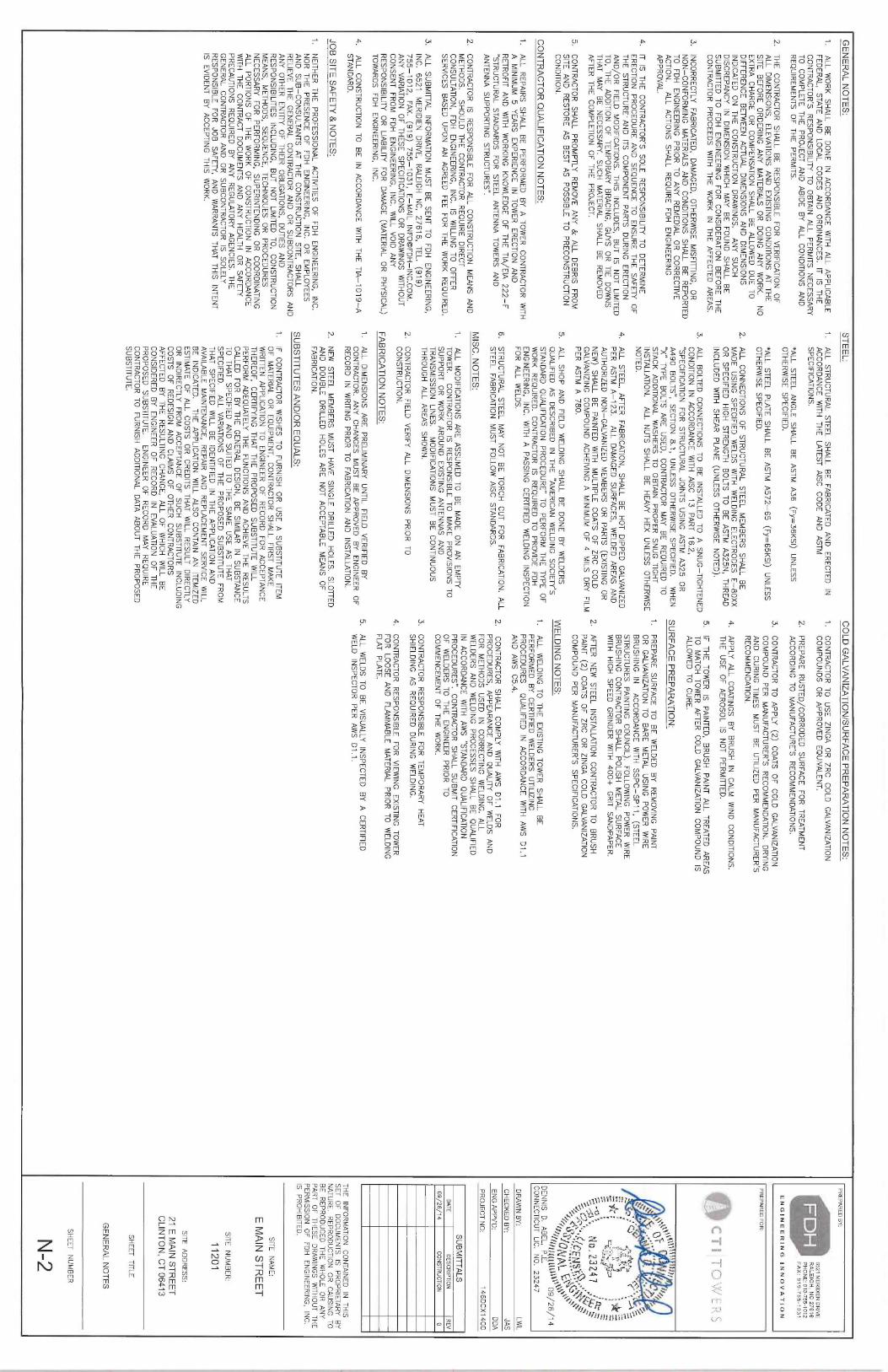
GENERAL NOTES:
1. ALL
WORK SHALL BE DONE IN
ACCORDANCE WITH
ALL APPLICABLE
FEDERAL, STATE AND LOCAL CODES AND ORDINANCES. IT
IS THE
CONTRACTOR'S RESPONSIBILITY T
O OBTAIN
ALL PERMITS NECESSARY
TO COMPLETE THE PROJECT AND ABIDE
BY ALL CONDITIONS AND
REQUIREMENTS OF THE PERMITS.
STEEL:
1. ALL S
TRUCTURAL STEEL SHALL BE FABRICATED
AND ERECTED IN
ACCORDANCE WITH
THE LATEST
AISC CODE AND ASTM
SPECIFICATIONS.
GALVANIZATION/SURFACE PREPARATION NOTES:
PREPARED BY:
6521 MERIDIEM DWVE
.
RALEIGH, NC 27616
PHONE: 919-755-1012
FAX: 919-755-1031
E N G I N
E E R I N
G
I N N O V A T I O
N2.
THE CONTRACTOR SHALL BE RESPONSIBLE FOR VERIFICATION
OF
ALL DIMENSIONS, ELEVATIONS
AND EXISTING
CONDITIONS AT THE
SITE BEFORE ORDERING ANY MATERIALS
OR DOING ANY WORK. NO
EXTRA CHARGE OR COMPENSATION SHALL BE ALLOWED DUE TO
DIFFERENCE BETWEEN ACTUAL DIMENSIONS AND DIMENSIONS
INDICATED ON THE CONSTRUCTION DRAWINGS. ANY SUCH
DISCREPANCY IN
DIMENSION WHICH MAY BE FOUND SHALL BE
SUBMITTED TO FDH ENGINEERING FOR CONSIDERATION BEFORE THE
GONTR4CTOR PROCEEDS WITH
THE WORK IN
THE AFFECTED AREAS.
3. INCORRECTLY FABRICATED, D
AMAGED, OTHERWISE MISFITTING, O
RNON-CONFORMING MATERIALS
AND CONDITIONS
SHALL BE REPORTED
TO FDH ENGINEERING PRIOR TO ANY REMEDIAL OR CORRECTIVE
ACTION. ALL ACTIONS SHALL REQUIRE FDH ENGINEERING
APPROVAL.
4. IT
IS THE CONTRACTOR'S SOLE RESPONSIBILITY T
O DETERMINE
ERECTION PROCEDURE AND SEQUENCE TO ENSURE THE SAFETY OF
THE STRUCTURE' AND ITS
COMPONENT PARTS DURING ERECTION
AND/OR FIELD
MODIFICATIONS. THIS INCLUDES, BUT IS
NOT LIMITED
T0, THE ADDITION
OF TEMPORARY BRACING, G
UYS OR TIE
DOWNS
THAT MAY BE NECESSARY. SUCH MATERIAL S
HALL BE REMOVED
AFTER THE. C
OMPLETION OF THE PROJECT.
5. CONTRACTOR SHALL PROMPTLY REMOVE ANY &ALL DEBRIS FROM
SITE AND RESTORE AS BEST AS POSSIBLE TO PRECONSTRUCTION
CONDITION.
1. ALL REPAIRS
SHALL BE PERFORMED BY A TOWER CONTRACTOR WITH
A MINIMUM
5 YEARS EXPERIENCE IN
TOWER ERECTION AND
RETROFIT AND WITH
WORKING KNOWLEDGE OF THE TIA/EIA
222-F
"STRUCTURAL STANDARDS FOR STEEL ANTENNA TOWERS AND
ANTENNA SUPPORTING STRUCTURES".
2. CONTRACTOR IS
RESPONSIBLE FOR ALL CONSTRUCTION MEANS AND
METHODS. SHOULD THE CONTRACTOR REQUIRE DIRECT
CONSULTATION, FDH ENGINEERING, INC. IS
WILLING TO OFFER
SERVICES BASED UPON AN AGREED FEE FOR THE WORK RERUIRED.
3. ALL SUBMITTAL INFORMATION
MUST BE SENT TO FDH ENGINEERING,
INC. 6521 MERIDIEM
DRIVE, RALEIGH NC, 27616, TEL. (
919)
755-1012, FAX. (
919) 755-1031, E-MAIL INFO~FDH-INC.COM.
ANY VARIATION
OF THESE SPECIFICATIONS
OR DRAWINGS WITHOUT
CONSENT FROM FDH ENGINEERING, INC. WILL
VOID ANY
RESPONSIBILITY OR LIABILITY
FOR DAMAGE (MATERIAL
OR PHYSICAL)
TOWARDS FDH ENGINEERING. INC.
4. ALL CONSTRUCTION TO BE IN
ACCORDANCE WITH
THE TIA-1019-A
STANDARD.
JOB SITE SAFETY 8~ N
OTES:
1. NEITHER
THE PROFESSIONAL ACTIVITIES
OF FDH ENGINEERING, INC.
NOR THE PRESENCE OF FDH ENGINEERING, INC. O
R EMPLOYEES
AND SUB-CONSULTANTS AT THE CONSTRUCTION SITE, S
HALL
RELIEVE THE GENERAL CONTRACTOR AND OR SUBCONTRACTORS AND
ANY OTHER ENTITY
OF THEIR
OBLIGATIONS, DUTIES AND
RESPONSIBILITIES INCLUDING, B
UT NOT LIMITED T
0, CONSTRUCTION
MEANS, METHODS, SEQUENCE, TECHNIQUES OR PROCEDURES
NECESSARY FOR PERFORMING, SUPERINTENDING OR COORDINATING
ALL PORTIONS OF THE WORK OF CONSTRUCTION IN
ACCORDANCE
WITH THE CONTRACT DOCUMENTS AND ANY HEALTH OR SAFETY
PRECAUTIONS REQUIRED BY ANY REGULATORY AGENCIES. T
HE
GENERAL CONTRACTOR AND OR SUBCONTRACTOR IS
SOLELY
RESPONSIBLE FOR JOB SAFETY, A
ND WARRANTS THAT THIS
INTENTIS
EVIDENT BY ACCEPTING THIS
WORK.
1. CONTRACTOR TO USE ZINGA OR ZRC COLD GALVANIZATION
COMPOUNDS OR APPROVED EQUIVALENT.
2. PREPARE RUSTED/CORRODED SURFACE FOR TREATMENT
*ALL STEEL ANGLE SHALL BE ASTM A36 (Fy=36K51) UNLESS
ACCORDING TO MANUFACTURE'S RECOMMENDATIONS.
OTHERWISE SPECIFIE0.
3. CONTRACTOR TO APPLY (2) COATS OF COLD GALVANIZATION
*ALL STEEL PLATE SHALL BE ASTM A572-65 (Fy=65KS1) UNLESS
COMPOUNQ PER MANUFACTURER'S RECOMMENDATION. DRYING
OTHERWISE SPECIFIED.
AND CURING TIMES
MUST BE UTILIZED
PER MANUFACTURER'S
2. ALL CONNECTIONS OF STRUCTURAL STEEL MEMBERS SHALL BE
RECOMMENDATION.
MADE USING
SPECIFIED WELDS WITH
WELDING ELECTRODES E-80XX
4. APPLY ALL COATINGS BY BRUSH IN
CALM WIND CONDITIONS.
OR SPECIFIED
HIGH STRENGTH BOLTS TO BE ASTM A325N, THREAD
THE USE OF AERpSOL IS
NOT PERMITTED.
INCLUDED WITH
SHEAR PLANE (UNLESS OTHERWISE NOTED).
5. IF T
HE TOWER IS
PAINTED, BRUSH PAINT A
LL TREATED AREAS
3. ALL BOLTED CONNECTIONS TO BE INSTALLED T
O ASNUG-TIGHTENED
TO MATCH TOWER AFTER COLD GALVANIZATION
COMPOUND IS
CONDITION IN
ACCORDANCE WITH
AISC 13 PART 16.2,
ALLOWED TO CURE.
"SPECIFICATION FOR STRUCTURAL JOINTS
USING ASTM A325 OR
A490 BOLTS", SECTION
8.1, UNLESS OTHERWISE SPECIFIED.
WHEN
SURFACE PREPARATION:
"X" TYPE BOLTS ARE USED, CONTRACTOR MAY BE REQUIRED TO
STACK ADQITIONAL
WASHERS TO OBTAIN
PROPER SNUG TIGHT
1. PREPARE SURFACE TO BE WELDED BY REMOVING PAINT
INSTALLATION. ALL NUTS SHALL BE HEAVY HEX UNLESS OTHERWISE
OR GALVANIZATION
TO BARE METAL USING PQWER WIRE
NOTED.
BRUSHING IN
ACCORDANCE WITH
SSPC-SP11, (STEEL
4. ALL STEEL, A
FTER FABRICATION, S
HALL BE HOT DIPPED GALVANIZED
STRUCTURES PAINTING
COUNCILj. FOLLOWING POWER WIRE
PER ASTM A-123.
ALL DAMAGED SURFACES, WELDED AREAS AND
BRUSHING CONTRACTOR SHALL POLISH
METAL SURFACE
AUTHORIZED NON-GALVANIZED MEMBERS OR PARTS (EXISTING
OR
WITH HIGH
SPEED GRINDER WITH 4
00+ GRIT S
ANDPAPER.
NEW) SHALL BE PAINTED
WITH MULTIPLE
COATS OF ZRC COLD
2, AFTER NEW STEEL INSTALLATION
CONTRACTOR TO BRUSH
GALVANIZING COMPOUND ACHEIVING
A MINIMUM OF 4 MILS
DRY FILM
PAINT (2) COATS OF ZRC OR ZINGA
COLD GALVANIZATION
PER ASTM A 780.
COMPOUND PER MANUFACTURER'S SPECIFICATIONS.
5. ALL SHOP AND FIELD
WELDING SHALL BE DONE BY WELDERS
y~IELDING NOTES:
QUALIFIED AS DESCRIBED IN
THE °A
MERICAN WELDING SOCIETY'S
STANDARD QUALIFICATION
PROCEDURE" TO PERFORM THE TYPE OF
1. ALL WELDING TO THE EXISTING
TOWER SHALL BE
WORK REQUIRED. CONTRACTOR IS
REQUIRED TO PROVIDE FDH
PERFORMED BY CERTIFIED
WELDERS UTILIZING
ENGINEERING, INC. WITH A PASSING CERTIFIED
WELDING INSPECTION
PROCEDURES
QUALIFIED IN
ACCORDANCE WITH
AWS D1.1
FOR ALL WELDS.
AND AWS C5.4.
6. STRUCTURAL STEEL MAY NOT BE TORCH CUT FOR FABRICATION. A
LL Z
STEEL FABRICATION
MUST FOLLOW AISC
STANDARDS.
MISC. NOTES:
1. ALL MODIFICATIONS
ARE ASSUMED TO BE MADE ON AN EMPTY
TOWER. CONTRACTOR IS
RESPONSIBLE TO MAKE PROVISIONS TO
SUPPORT OR WORK AROUND EXISTING
ANTENNAS AND
TRANSMISSION LINES.
MODIFlCATIONS MUST BE CONTWUOUS
THROUGH ALL AREAS SHOWN.
2. CONTRACTOR FIELD
VERIFY ALL DIMENSIONS PRIOR TO
CONSTRUCTION.
FABRICATION NOTES:
1. ALL DIMENSIONS ARE PRELIMINARY
UNTIL FIELD
VERIFIED BY
CONTRACTOR. AM' CHANGES MUST BE APPROVED BY ENGINEER OF
RECORD IN
WRITING PRIOR TO FABRICATION
AND INSTALLATION.
CONTRACTOR SHALL COMPLY WITH
AWS D1.1
FOR
PROCEDURES, APPEARANCE AND QUALITY
OF WELDS AND
FOR. METHODS USED IN
CORRECTING WELDING. ALL
WELDERS AND WELDING PROCESSES SHALL BE QUALIFIED
IN ACCORDANCE WITH
AWS "STANDARD QUALIFICATION
PROCEDURES". CONTRACTOR SHALL SUBMIT CERTIFICATION
OF WELDERS TO THE ENGINEER PRIOR TO
COMMENCEMENT OF THE WORK.
3. CONTRACTOR RESPONSIBLE FOR TEMPORARY HEAT
SHIELDING AS REQUIRED DURING WELDING.
4. CONTRACTOR RESPONSIBLE FOR VIEWING
EXISTING TOWER
FOR LOOSE AND FLAMMABLE MATERIAL
PRIOR TO WELDING
FLAT PLATE.
5. ALL WELDS TO BE VISUALLY
INSPECTED BY A CERTIFIED
WELD INSPECTOR PER AWS D1.1.
2. NEW STEEL MEMBERS MUST HAVE SINGLE DRILLED
HOLES. SLOTTED
AND DOUBLE DRILLED
HOLES ARE NOT ACCEPTABLE MEANS OF
FABRICATION.
SUBSTITUTES AND/OR EQUALS:
1. IF
CONTRACTOR WISHES TQ FURNISH OR USE A SUBSTITUTE
ITEMOF MATERIAL
OR EQUIPMENT, CONTRACTOR SHALL FIRST
MAKE
WRITTEN APPLICATION
TO ENGINEER OF RECORD FOR ACCEPTANCE
THEREOF, CERTIFYING T
HAT THE PROPOSED SUBSTITUTE WILL
PERFORM ADEQUATELY THE FUNCTIONS AND ACHIEVE T
HE RESULTS
CALLED FOR BY THE GENERAL DESIGN, B
E SIMILAR
IN SUBSTANCE
TO THAT SPECIFIED
AND SUITED
TO THE SAME USE AS THAT
SPECIFlED. ALL VARIATIONS
OF THE PROPOSED SUBSTITUTE FROM
THAT SPECIFIED
WILL BE IDENTIFIED
IN THE APPLICATION
AND
AVAILABLE MAINTENANCE, REPAIR
AND REPLACEMENT .SERVICE
WILLBE INDICATED.
THE APPLICATION
WILL ALSO CONTAIN
AN ITEMIZED
ESTIMATE OF ALL COSTS OR CREDITS T
HAT WILL
RESULT DIRECTLY
OR INDIRECTLY
FROM ACCEPTANCE QF SUCH SUBSTITUTE INCLUDING
COSTS OF REDESIGN AND CLAIMS
OF OTHER CONTRACTORS
AFFECTED BY THE RESULTING CHANGE, ALL OF WHICH WILL B
ECONSIDERED BY ENGINEER OF RECORD IN
EVALUATIQN OF THE
PROPOSED SUBSTITUTE.
ENGINEER OF RECORD MAY REQUIRE
CONTRACTOR TO FURNISH ADDITIONAL
DATA ABOUT THE PROPOSED
SUBSTITUTE.
PREPARED FOR
~~ ~ ~ ~
l ~~E{~~
a~
'~~. ~J
~t~'r~y
i~ ,fir-
r
~„
mfr Ott; ~:;~'ChIS~"a~`'~yfi~`
rjJfi'~~~~1S1r4 ~{ ~
~o9,t26
14
DENNIS D. ABEL, P,E.
/ /
CONNECTICUT LIC.
N0. 23247
DRAWN BY:
LWL
CHECKED 6Y:
JAS
ENG APPV'D:
DDA
PROJECT NO:
146DCX1400
SUBMITTALS
DATE
DESCRIPTION
REV
09/2fi/14
CONSTRUCTION
0
THE INFORMATION
CONTAINED IN
THISSET O
F DOCUMENTS IS
PROPRIETARY BY
NATURE.. REPRODUCTION OR CAUSING T
OBE REPRODUCED THE WHOLE OR ANY
PART OF THESE DRAWINGS
WITHOUT THE
PERMISSION OF FDH ENGINEERING, INC.
IS PROHIBITED.
SITE NAME:
E MAIN STREET
SITE NUMBER:
11201
SITE ADDRESS:
21 E MAIN STREET
CLINTON, CT 06413
SHEET TITLE
GENERAL NOTES
SHEET NUMBER
N-2
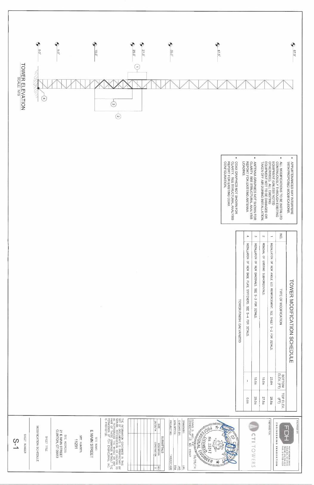
• APPURTENANCES MAY INTERFERE
WITH PROP05ED MODIFICATIONS.
• ALL MODIFICATIONS TO BE INSTALLED
CONTINUOUSLY THROUGH EXISTING
EQUIPMENT (UNLESS NOTED
OTHERWISE). ALL EXISTING
EQUIPMENT NOT TO BE DAMAGED OR
TAKEN OFF AIR DURING INSTALLATION.
• ANTENNA GRAPHICS NOT SHOWN FOR
CLARITY. SEE STRUCTURAL ANALYSIS
REPORT FOR EXISTING ANTENNA
LOADING.
• COAX GRAPHICS NOT SHOWN FOR
CLARITY. SEE STRUCTURAL ANALYSIS
REPORT FOR EXISTING COAX
CONFIGURATION.
TOWER MODIFICATION SCHEDULE
BOTTOM
TOP ELEV.
NO.
TYPE OF MODIFICATION
ELEV. (FT)
(FT)
1 INSTALLATION
OF NEW ANGLE LEG REINFORCEMENT. SEE SHEEP S-2 FOR DETAILS.
23.81
28.81
2
REMOVAL OF EXISTING
SUBHORIZONTALS.
15.Ot
27.51
3
INSTALLATION OF NEW DIAGONALS. S
EE S-3 FOR DETAILS.
15.Of
25.Ot
4
INSTALLATION OF NEW BASE PLATE STIFFENERS. S
EE S-4 FOR DETAILS.
-
O.Of
TOWER FINISH: G
ALVANIZED
PREPARED BY:
6521 MERIDIEN DRIVE
■
RALEIGH, NC 27616
PHONE: 919-755-1072
FAX: 919-755-1031
ENGINEERING INNOVATION
PREPARED FORCTI T~?~X%`ERS
d~.
r,
r~,~'
S'/ ~~'
~
~f`r~ ~<<!1►~~~144tiS~~~09/26/14
DENNIS D. ABEL, P.E.
CONNECTICUT LIC.
N0. 23247
DRAWN BY:
LWL
I
CHECKED BY:
JAS
ENG APPV'D:
DDA
SUBMITTALS
~AlE
DESCRIPTION REV
09/26/14
CONSTRUCTION
0
PROJECT NO:
146DCX1400
THE INFORMATION
CONTAINED IN
THISSET OF DOCUMENTS IS
PROPRIETARY BY
NATURE. REPRODUCTION OR CAUSING T
OBE REPRODUCED THE WHOLE OR ANY
PART OF THESE DRAWINGS WITHOUT T
HE
PERMISSION OF FDH ENGINEERING, INC.
IS PROHIBITED.SITE NAME:
E MAIN STREET
SITE NUMBER:
11201
~
~
SITE ADDRESS:
21 E MAIN STREET
CLINTON, CT 06413
SHEEP TITLE
~ ~~
TOWER ELEVATION
SCALE: NTS
MODIFICATION SCHEDULE
SHEET NUMBER
S-1
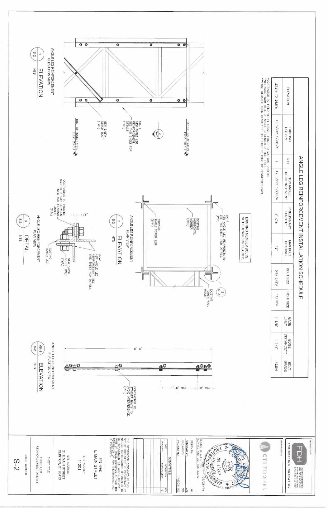
ANGLE LEG REINFORCEMENT INSTALLATION SCHEDULE
EXISTING
NEW ANGLE
PRELIMINARY
MAX BOLT
GAGE
EDGE
BOLT
ELEVATION
LEG SIZE
4TM'
REINFORCEMENT
LENGTH'
SPACING
BOLT SIZE
HOLE SIZE
LINE*'
DISTANCE*"*
GRADE
23.8'f TO 28.8't
L2 1/2X2 1/2X1/4
8
L2 1/2X2 1/2X1/4
g'_p"f
18"
(48) 5/8"0
11/16"~
1 3/8"
1 1/4"
A325N
*CONTRACTOR TO FIELD
VERIFY LENGTH PRIOR TO MATERIAL ORDERS.
**DISTANCE FROM HEEL OF ANGLE TO CENTER OF BOLT HOLE.
***EDGE DISTANCE FRpM CENTER OF BOLT HOLE TO EDGE OF CONNECTEQ PART.
EXISTING MEMBER BOLTS
NOT SHOWN FOR CLARITY.
I~
AI
Q
~~ ~_
~~
\~
~
~ '~~~`. A
I
~~
I~
~I
`~
~
I~`
If ;Ji ,
f'
~~
~r=' i
~
,;~" ,:
II
I~
i~
~~
ANGLE LEG REINFORCEMENT
ELEVATION VIEW
~ ELEVATION
S-2
NTS
TOP OF INSTALLATION ~ELEV: 2
8.8'f
2
5—z
MK-1
NEW ANGLE LEG
REINFORCEMENT.
SEE THIS
SHEET FOR
DETAILS.(7YP.)
NEW 5/8"0
STITCH BOLT
(TrP.)
BTM. OF INSTALLATION ~ELEV: 2
3.8
MK-1
NEW ANGLE LEG REINFORCEMENT
SEE THIS
SHEEP FOR DETAILS.
(TYP.)
ANGLE LEG REINFORCEMENT
PLAN VIEW
~ ELEVATION
S 2
NTS
3'~
5-3
i
~
~ ~ i
EXISTINGTOWER WALL
MOUNT
MK-1
NEW ANGLE LEG
REINFORCEMENT. SEE
THIS SHEET FOR DETAILS.
~~~~~
NEW 5/8'0
CONTRACTOR TO PRaVIDE
STITCH BOLT.
WASHER IN
GAP 6EfWEEN
~ ~~P'~
NEW AND EXISTINGANGLE.
~NP
~~ '~ EXISTINGTOWER LEG
ANGLE LEG REINFORCEMENT
PLAN VIEW
s DETAIL
S-2
NTS
0,~
I0TXmCONTRACTOR TO
STAGGER BOLTS TO
AVOID INTERFERENCE.
~~•)
ANGLE LEG REINFORCEMENT
ELEVATION VIEW
MK-1
ELEVATION
S-2
NTS
PREPARED BY:
6521 MERIDIEN DRIVE
.
RALEIGH, NC 27616
PHONE: 919-755-1012
FAX: 919-755-1031
ENGINEERING INNOVATION
PREPARED FOR:~Q~ ~
r ;;e~
.i[ '`~.
~~y
i~
~~L ,:_q~
~S ~
• ~f.
f~f ~~i; ~:~Z'~'~15~~`~~ty~~`
fi{f,~~~~~(l
l 61~~09/26/14
DENNIS D. ABEL, P.E.
CONNECTICUT LIC.
N0. 23247
DRAWN BY:
LWL
CHECKED 8Y:
JAS
ENG APPV'~:
DMA
PROJECT NO:
146DCX1400
SUBMITTALS
~A7E
DESCRIPTION
REV
09/26/14
CONSiF2UCTI0N
0
THE INFORMATION
CONTAINEd IN
THISSET OF DOCUMENTS IS P
ROPRIETARY BY
NATURE. REPRODUCTION OR CAUSING
TO
BE REPRODUCED THE WHOLE OR ANY
PART OF THESE DRAWINGS WITHOUT T
HE
PERMISSION OF FDH ENGINEERING, INC.
is PROHisirEo.SITE NAME:
E MAIN STREET
SITE NUMBER:
11201
SITE ADDRESS:
21 E MAIN STREET
CLINTON, CT 06413
SHEET TITLE
ANGLE LEG
REINFORCEMENT DETAILS
SHEET NUMBER
S-2
EXISTINGHORIZONTAL
MEMBER
(NP.)
EXISTINGANGLE TOWER LEG
(NP.)
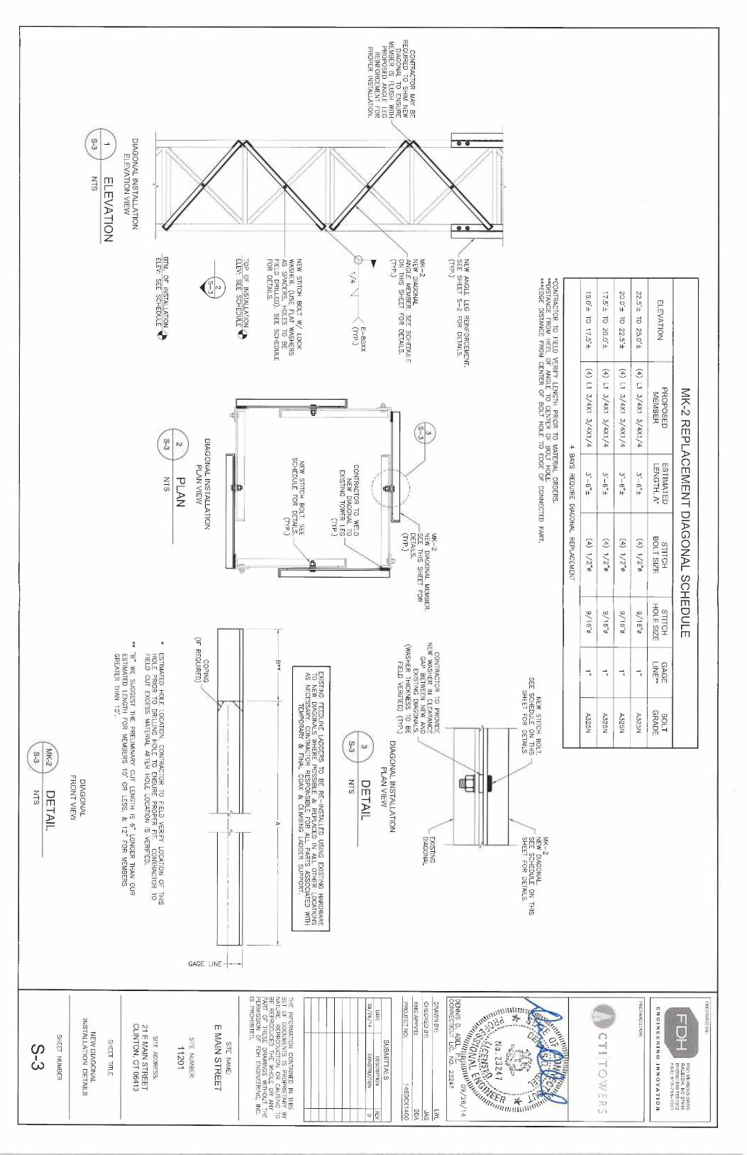
MK-2 R
EPLACEMENT DIAGONAL SCHEDULE
ELEVATION
PROPOSED
ESTIMATED
STITCH
STITCH
GAGE
BOLT
MEMBER
LENGTH, A*
BOLT SIZE
HOLE SIZE
LINE*
GRADE
22.5~t TO 25.0't
(4) L1
3/4X1 3/4X1/4
3'-6"t
(4) 1/2"0
9/16"0
~"
A325N
20.0't TO 22.5'f
(4) L1
3/4X1 3/4X1/4
3'-6"f
(4) 1/2"~
9/16"~
~"
A325N
17.5'f TO 2D.0'f
(4) L1
3/4X1 3/4X1/4
3'-6"t
(4) 1/2"~
9/16"0
~"
A325N
15.0'f TO 17.5'f
(4) L1
3/4X1 3/4X1/4
3'-6"f
~4) ~~2"~
9/16"~
~"
A325N
4 BAYS REQUIRE DIAGONAL REPLACEMENT
*CONTRACTOR TO FIELD
VERIFY LENGTH PRIOR TO MATERIAL ORDERS.
**DISTANCE FROM HEEL OF ANGLE TO CENTER OF BOLT HOLE.
***EDGE DISTANCE FROM CENTER OF BOLT HOLE TO EDGE OF CONNECTED PART.
NEW STITCH
BOLT.
SEE SCHEDULE ON THIS
SHEET FOR DETAILS.
MK-2
NEW DIAGQNAL.
SEE SCHEDULE ON THIS
SHEET FOR DETAILS.
\\
NEW ANGLE LEG REINFORCEMENT.
SEE SHEEP S-2 FOR DETAILS.
(NP.)
MK-2
CONTRACTOR TO PROVIDE
EXISTING3
MEW DIAGONAL MEMBER.
NEW WASHER IN
CLEARANCE
DIAGONAL
MK-2
S-3
SEE THIS SHEEP FOR
GAP BETWEEN NEW AND
CONTRACTOR MAY BE
NEW DIAGONAL
DETAILS. EXISTING
DIAGONALS.
REQUIRED TO SHIM NEW
ANGLE MEMBER. SEE SCHEDULE
~-'~>\
(WASHER THICKNESS TO BE
ON THIS
SHEET FOR DETAILS.
~P~~
FIELD VERIFIED) (
NP.)
DIAGONAL TO ENSURE
iMEMBER IS
FLUSH WITH
~nP•~
~ DIAGONAL INSTALLATION
PROPOSED ANGLE LEG
~ i
PLAN VIEW
REINFORCEMENT FOR
PROPER INSTALLATION.
E-80XX
3
DETAIL
~ (7yp,)
CONTRACTOR TO WELD
~~
NEW DIAGONAL TO
S-3
NT5
EXISTING TOWER LEG
(7YP.)
~
EXISTING FEEDLINE LADDERS TO BE RE-INSTALLED USING EXISTING
HARDWARE
~\
TO NEW DIAGONALS WHERE POSSIBLE & REPLACED IN
ALL OTHER LOCATIONS
AS NECESSARY. CONTRACTOR RESPONSIBLE FOR ALL PARTS ASSOCIATED WITH
\\~
NEW STITCH
BOLT W/ LOCK
NEW STITCH
BOLT. SEE
TEMPORARY &FINAL COAX &CLIMBING LADDER SUPPORT.
WASHER. (USE FLAT WASHERS
SCHEDULE FOR DETAILS.
AS SPACERS, HOLES TO BE
~nP
•~FIELD
DRILLED). SEE SCHEDULE
B'*
AFOR DETAILS.
TOP OF INSTALLATION ~
__ ELEV: S
EE SCHEDULE
__,
r,~
-~
2
wzS-3
DIAGONAL INSTALLATION
COPING
~PLAN VIEW
(IF REQUIRED)
Qc~
2 PLAN
BTM. OF INSTALLATION ~
S-3
NTS
.~
ELEV: SEE SCHEDULE
*
ESTIMATED HOLE LOCATION. CQNTRACTOR TO FIELD
VERIFY LOCATION OF THIS
HOLE PRIOR TO DRILLING
HOLE TO ENSURE PROPER FIT.
CONTRACTOR TO
FIELD CUT EXCESS MATERIAL AFTER HOLE LOCATION IS VERIFIED.
DIAGONAL INSTALLATION
** "B" WE SUGGEST THE PRELIMINARY CUT LENGTH IS
6" LONGER THAN OUR
ELEVATION VIEW
ESTIMATED LENGTH FOR MEMBERS 1D' OR LESS, & 12" FOR MEMBERS
GREATER THAN i0'.
~ ELEVATION
5-3
NTS
DIAGONAL
FRONT VIEW
MK-2
DETAIL
S-3
NTS
PF2EPARED BY:
6527 MERIDIEN DRIVE
■
RALEIGH, NC 27616
PHONE: 919-755-1012
FAX; 919-755-103t
ENGINEERING INNOVATION
PREPARED FOR:
CTI T~?WERS
a~-
M: ~.~ "%
i i
~'
~f°~tr 4. Ua
~ bi27"
a (~.
"ms's ~. C~ a . 2
3 Z Q 7 ,
c~,
Jrr'! ~~~~1[U 1 ~ ~~09/26/14
DENNIS D. ABEL, P.E.
CONNECTICUT LJC,
N0. 23247
DRAWN BY:
LWL
CHECKED BY:
JAS
ENG APPV'D:
DDA
PROJECT NO:
146DCX 1400
SUBMITTALS
DATE
DESCRIPTION REV
09/26/14
CONSTRUCTION
0
THE INFORMATION
CONTAINED IN
THISSET OF DOCUMENTS IS P
ROPRIETARY BY
NATURE. REPRODUCTION OR CAUSING TO
BE REPRODUCED THE WHOLE OR ANY
PART OF THESE DRAWINGS WITHOUT T
HE
PERMISSION OF FDH ENGINEERING, INC.
IS PROHIBITED.
SITE NAME:
E MAIN STREET
SITE NUMBER:
11201
SITE ADDRESS:
21 E MAIN STREET
CLINTON, CT 06413
SHEET TITLE
NEW DIAGONAL
INSTALLATION DETAILS
SHEET NUMBER
S-3
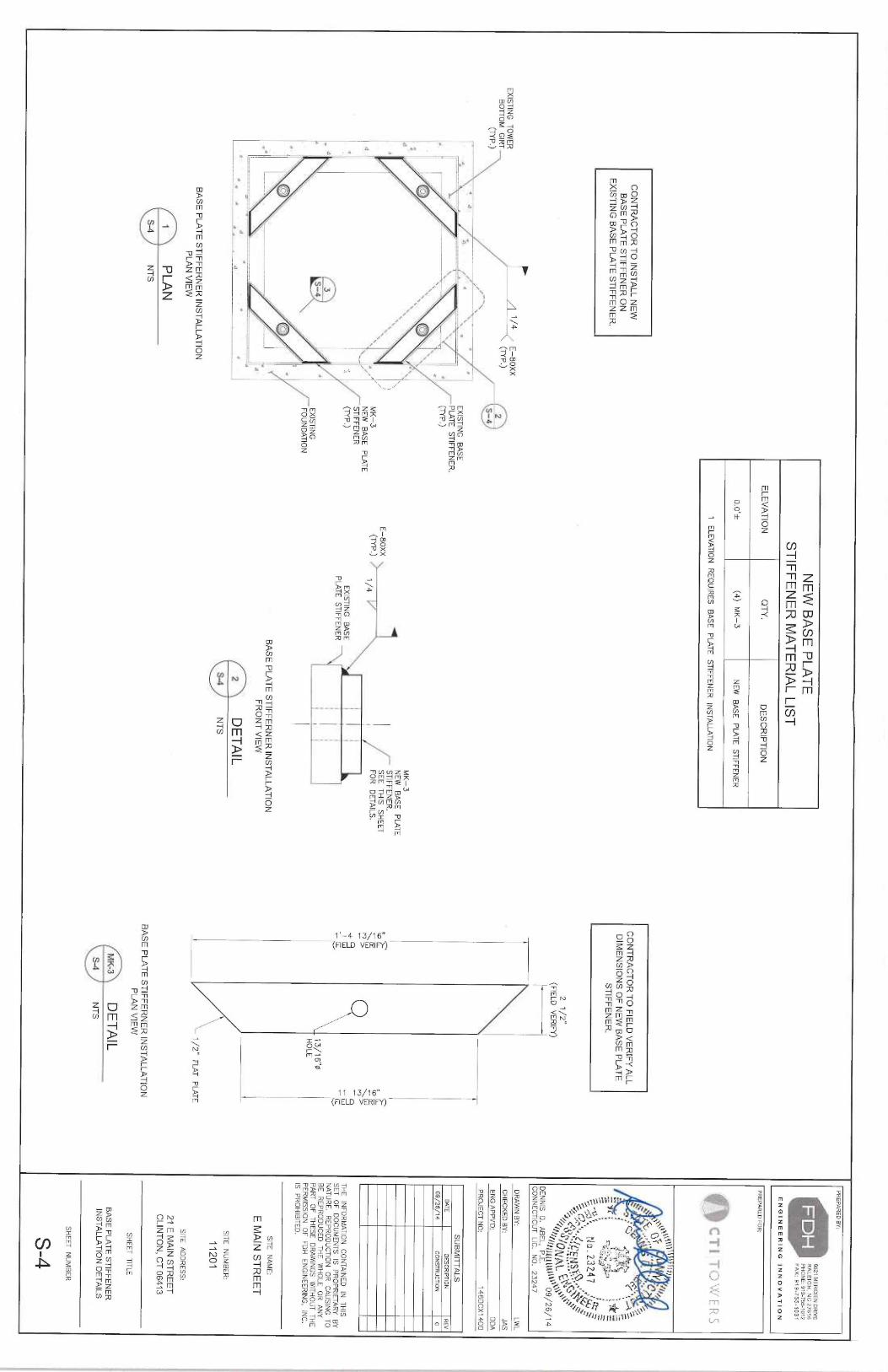
NEW BASE PLATE
STIFFENER MATERIAL LIST
ELEVATION
QTY.
DESCRIPTION
0.0't (4) MK-3
NEW BASE PLATE STIFFENER
1 ELEVATION
REQUIRES BASE PLATE STIFFENER
INSTALLATION
CONTRACTOR TO INSTALL NEW
BASE PLATE STIFFENER ON
EXISTING BASE PLATE STIFFENER.
EXISTING TOWER
~~4
E-80XX
BOTTOM GIRT
~NP•~
2(TYP.) ~
S-4
i"~
' ~
~
i.
~\
~.
i~\ `~
l
~~\
~\
~i~~~
`~
.%~
`~
ade
\k~\
f~
f'
,,
~
~
3S-4
~,'
ri~
L %
Oy., j'
%'
~ .
BASE PLATE STIFFERNER INSTALLATION
PLAN VIEW
~ PLAN
S-4
NTS
CONTRACTOR TO FIELD VERIFY ALL
DIMENSIONS OF NEW BASE PLATE
STIFFENER.
2 1/2"
(FIELD VERIFY)
~ j
\ j
O
~~~~W
\
~9
~~
\
T~
13/16"~
HOLE
EXISTING BASE
PLATE STIFFENER.
(NP.)
.\i~
MK-3
NEW BASE PLATE
STIFFENER
~~•)
E-80XX \
(NP.) 4
MK-3
NEW BASE PLATE
STIFFENER.SEE THIS
SHEET
FOR DETAILS.
EXISTINGFOUNDATION
EXISTING BASE
~ '
iPLATE STIFFENER
i i
i i
i i
~ i
i ~
i
BASE PLATE STIFFERNER INSTALLATION
FRONT VIEW
z DETAIL
S-4
NTS
PREPARED BY:
fi521 MERIDIEN DRIVE
RALEIGH, NC 27816
PHONE: 919-755-1012
_.
FAX: 919-755-1031
ENGINEERING INNOVATION
PREPARED FOR:
CTI TQWERS
~~..
V~
~. t~'r-r~ 'ice .
~~L "l
r : .~ ~
'~
.-. Ya i ~. '
_.~~,
ti ~;,'
~ --
~ ray~7
j
`~ ~ ~to.'L32~7
,'k~'
'~.~ ~~cL~ ~~~',Ef;1S;~4~~~~~S
~~r/~f's~~i[u ►~~' os
/zs/~ 4
DENNIS D. ABEL, P.E.
CONNECTICUT LIC.
N0. 23247
DRAWN BY:
LWL
CHECKED BY:
JAS
ENG APPV'~:
DDA
PROJECT NO:
146DCX 1400
SUBMITTALS
DATE
DESCRIPTION
REV
09/26/14
CONSTRUCTION
0
THE INFORMATION
CONTAINED IN
THISSEf O
F DOCUMENTS IS PROPRIETARY
BYNATURE. REPRODUCTION
OR CAUSING T
OBE REPRODUCED THE WHOLE OR ANY
PART OF THESE DRAWINGS WITHOUT T
HE
PERMISSION OF FDH ENGINEERING, INC.
IS PROHIBITED.SITE NAME:
E MAIN STREET
SITE NUMBER:
~\ 11201
~ 1/2" FLAT
PLATE
SITE ADDRESS:
21 E MAIN STREET
CLINTON, CT 06413
BASE PLATE STIFFERNER INSTALLATION
PLAN VIEW
SHEET TITLE
BASE PLATE STIFFENER
INSTALLATION DETAILS
MK-3
DETAIL
S-4
NT5
SHEET NUMBER
S-4

FDH
FDH Engineering, Inc., 6521 Meridien Drive, Raleigh, NC, 27616, Ph. 919.755.1012, Fax 919.755.1031
December 19, 2014
Ms. Mikala MannCTI Towers, Inc.38 Pond Street, Suite 305Franklin, MA 02038
RE: 67.5' Lattice TowerCTI Towers Site Name: E Main St ClintonCTI Towers Site ID: 11021T-Mobile Site Name: Clinton/ I-95/ X63/ At 1T-Mobile Site ID: CT11031BSite Address: 21 E Main Street, Clinton, CT 06413FDH Project Number: 1461DM1400
Dear Mikala:
Per your request, FDH Engineering, Inc. has reviewed the previous structural analysis and the revised loadingfor the 67.5' Lattice Tower located in Clinton, CT. The previous structural analysis report by FDH Engineering,Inc. (Project No. 146HAZ1400) dated November 21, 2014, stipulates the tower was analyzed with theappurtenance loading outlined in Table 1 on the following page.
Based on the working percentage calculated in the previous analysis, the load resulting from the currentconfiguration (see Table 1) combined with T-Mobile's revised loading (see Table 2), will not overstress thetower and will meet the requirements of the TIA/EIA-222-F standards, provided the modifications outlined inFDH engineering, Inc. (Project No. 146DCX1400) have been correctly installed. Furthermore, since nofoundation information was available at the time of the analysis, we cannot comment on the capacity of thefoundation at this time. The existing coax should be used with the existing and proposed equipment.
Our assessment has been made assuming all information provided to FDH Engineering, Inc. is accurate andthat the tower has been properly erected and maintained.
In conclusion, the revised T-Mobile installation should meet or exceed all applicable standards and shouldtherefore be considered safe. Should you require additional information, please do not hesitate to contact ouroffice.
Reviewed By:Sincerely,
~~ ~~
Drew Alexander, EIProject Engineer
Dennis D. Abel, PEDirector—Structural EngineeringCT PE License No. 23247
~\ ~,e ~ aJ r~~
'~ ~, ~
f~1I~ jSStill~h
~~9-~~`~
Document No: ENG-RPT-504S Revision Date: 1118/10
Structural Evaluation LetterCTI Towrs
Site ID: 11021December 19, 2014
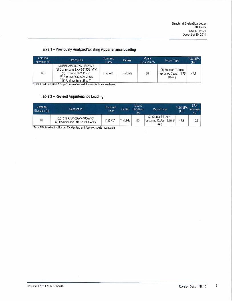
Table 2 —Revised Appurtenance Loading
60 (3) RFS APX16DWV-16DWVS
(3) Commscope LNX-6515DS-VTM
Total EPA listed without ice per TIA standard
(3) Standoff T-Arms(12) 7/8" T-Mobile 60 (assumed CaAa = 3.75 ft2 42.8 -10.3
ea.lnot include mount area.
Document No: ENG-RPT-504S Revision Date: 1/18/10
Table 1—Previously AnalyzedlExisting Appumenance Loading
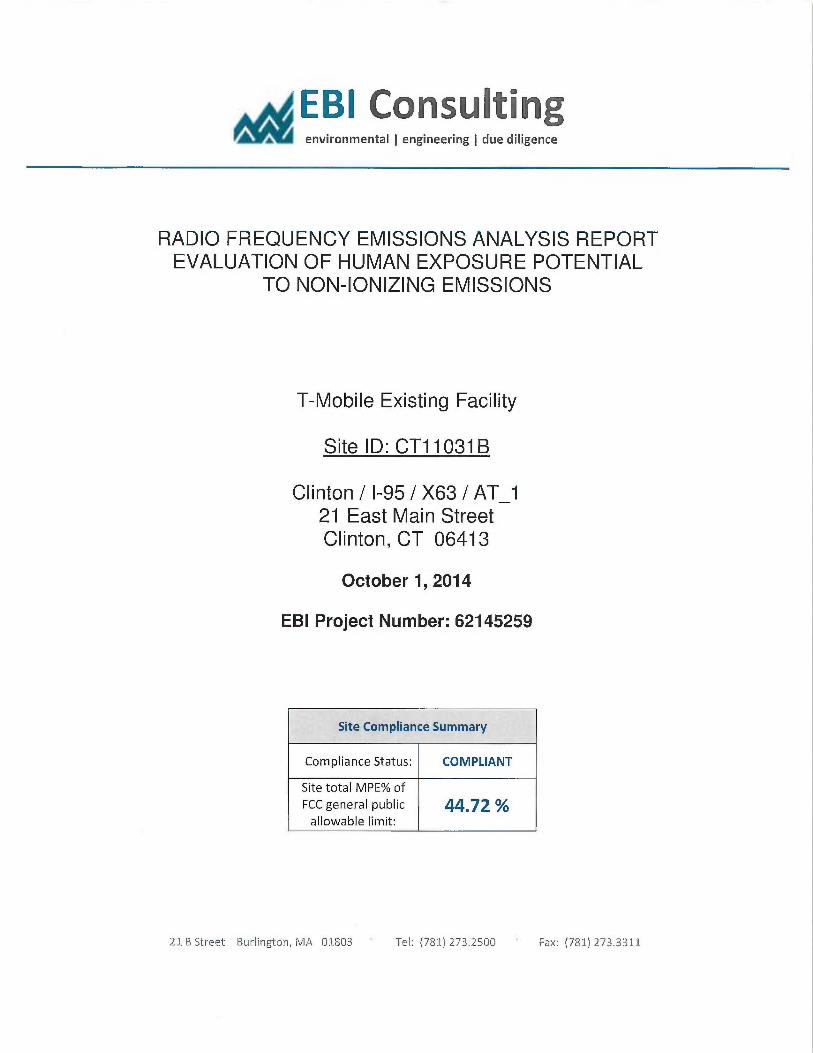
EBI consulting~, environmental ~ engineering ~ due diligence
RADIO FREQUENCY EMISSIONS ANALYSIS REPORTEVALUATION OF HUMAN EXPOSURE POTENTIAL
TO NON-IONIZING EMISSIONS
T-Mobile Existing Facility
Site ID: CT11031 B
Clinton / I-95 /X63 / AT 121 East Main StreetClinton, CT 06413
October 1, 2014
EBI Project Number: 62145259
Site Compliance Summary
Compliance Status: COMPLIANT
Site total MPE% ofFCC general public 44.72allowable limit:
21 B Street Burlington, MA 01803 Tel: (781) 273.250Q Fax: (781) 273.3311
EBI Consulting~, environmental ~ engineering ~ due diligence
October 1, 2014
T-Mobile USAAttn: Jason Overbey, RF Manager35 Griffin Road SouthBloomfield, CT 06002
Emissions Analysis for Site: CT11031B —Clinton / I-95 /X63 / AT_1
EBI Consulting was directed to analyze the proposed T-Mobile facility located at 21 East Main Street,Clinton, CT, for the purpose of determining whether the emissions from the Proposed T-Mobile Antenna
Installation located on this property are within specified federal limits.
All information used in this report was analyzed as a percentage of current Maximum Permissible
Exposure (% MPE) as listed in the FCC OET Bulletin 65 Edition 97-Oland ANSUIEEE Std C95.1. The
FCC regulates Maximum Permissible Exposure in units of microwatts per square centimeter (µW/cm2).
The number of µW/cm2 calculated at each sample point is called the power density. The exposure lunit
for power density varies depending upon the frequencies being utilized. Wireless Carriers and Paging
Services use different frequency bands each with different exposure limits, therefore it is necessary to
report results and limits in terms of percent MPE rather than power density.
All results were compared to the FCC (Federal Communications Commission) radio frequency exposurerules,. 47 CFR 11307(b)(1) — (b)(3), to determine compliance with the M~imum Permissible Exposure
(MPE) limits for General Population/iJncontrolled environments as defined below.
General population/uncontrolled exposure limits apply to situations in which the general public may beexposed or in which persons who are exposed as a consequence of their employment may not be made
fully aware of the potential for exposure or cannot exercise. control over their exposure. Therefore,.
members of the general public would always be considered under this. category when exposure is not.
employment related, for example, in the case of a telecommunications tower that exposes persons in anearby residential area.
Public exposure to radio frequencies is regulated and enforced in units of mierowatts per square
centimeter (µW/cm2). The general population exposure lunit for the 700 MHz Band is 467 µW/cm2, and
the general population exposure limit for the PCS and AWS bands is 1000 µW/cmZ. Because each carrier
will be using different frequency bands, and each frequency band has different exposure limits, it is
necessary to report percent of MPE rather than power density.
21 B Street 'Burlington, MA 01$03 Tel: (781} 273.250Q ~ Fax: (7S1) 273.3311
EBI Consulting~, environmental ~ engineering ~ due diligence
OccupationaUcontrolled exposure limits apply to situations in which persons are exposed as a
consequence of their employment and in which those persons who are exposed have been made fully
aware of the potential for exposure and can exercise control over their exposure. OccupationaUcontrolled
exposure limits also apply where exposure is of a transient nature as a result of incidental passage through
a location where exposure levels may be above general population/uncontrolled limits (see below), as
long as the exposed person has been made fully aware of the potential for exposure and can exercise
control over his or her exposure by leaving the area ar by some other appropriate means.
Additional details can be found in FCC OET 65.
CALCULATIONS
Calculations were done for the proposed T-Mobile Wireless antenna facility located at 21 East Main
Street, Clinton, CT, using the equipment information listed below. All calculations were performed per
the specifications under FCC OET 65. Since T-Mobile is proposing highly focused directional panel
antennas, which project most of the emitted energy out toward the horizon, all calculations were
performed assuming a lobe representing the maximum gain of the antenna per the antenna manufactures
supplied specifications, minus 10 dB, was focused at the base of the tower. For this report the sample
point is the top of a 6 foot person standing at the base of the tower.
For all calculations, all equipment was calculated using the following assumptions:
1) 2 GSM channels (PCS Band - 1900 MHz) were considered for each sector of the proposed
installation. These Channels have a transmit power of 30 Watts per Channel
2) 2 UMTS channels (AWS Band — 2100 MHz) were considered for each sector of the proposed
installation. These Channels have a transmit power of 30 Watts per Channel.
3) 2 LTE channels (AWS Band — 2100 MHz) were considered for each sector of the proposed
installation. These Channels have a transmit power of 60 Watts per Channel.
4) 1 LTE channel (700 MHz Band) was considered for each sector of the proposed installation.
This channel has a transmit power of 30 Watts.
5) All radios at the proposed installation were considered to be running at full power and were
uncombined in their RF transmissions paths per carrier prescribed configuration. Per FCC
OET Bulletin No. 65 -Edition 97-01 recommendations to achieve the ma~mum anticipated
value at each sample point, all power levels emitting from the proposed antenna installation
are increased by a factor of 2.56 to account for possible in-phase reflections from the
surrounding environment. This is rarely the case, and if so, is never continuous.
21 B Street Burlington, MA 018t13 Tel: (781) 273.25Q0 ~ Fax: (781) 273.3311
E61 Consultingi environmental ~ engineering ~ due diligence
6) For the following calculations the sample point was the top of a sic foot person standing at
the base of the tower. The malcimum gain of the antenna per the antenna manufactures
supplied specifications minus 10 dB was used in this direction. This value is a very
conservative estimate as gain reductions for these particular antennas are typically much
higher in this direction.
7) The antennas used in this modeling are the RFS APXI6DWV-16DWVS-E-A20 for 1900MHz (PCS) and 2100 MHz (AWS) channels and the Conunscope LNX-6515DS-VTM for
700 MHz channels. This is based on feedback from the carrier with regazds to anticipated
antenna selection. The RFS APXI6DWV-16DWV5-E-A20 has a maximum gain of 16.3
dBd at its main lobe. The Commscope LNX-6515DS-VTM has a maximum gain of 14.6
dBd at its main lobe. The maximum gain of the antenna per the antenna manufacturessupplied specifications, minus 10 dB, was used for all calculations. This value is a very
conservative estimate as gain reductions for these particular antennas are typically much
higher in this direction.
8) The antenna mounting height centerline of the proposed antennas is 60 feet above ground
level (AGL).
9) Emissions values for additional carriers were taken from the Connecticut Siting Council
active database. Values in this database are provided by the individual carriers themselves.
All calculations were done with respect to uncontrolled /general public threshold limits.
21 B Street Burlington, MA 01803 Tel: (781) 273.250 ~ Fax: (781) 273.3311

EBI Consulting1 environmental ~ engineering ~ due diligence
T-Mobile Site Inventory and Power Data
Sector: A Sector: B Sector:Antenna #: 1 Antenna #: 1 Antenna #: 1
RFS APXI6DWV- RFS APXI6DWV- RFS APXI6DWV-MakelModel: 16DWVS-E-A20
Make/Model: 16DVJVS-&A20
MakelModel: 16DVWS-E-A20
Gain: 163 dBd Gain: 163 dBd Crain: 163 dBdHei t (AGL): 60 Hei ht (AGL): 60 Hei ht (AGL): 60
Frequency Bands 1900 MHz(PCS) /
Frequency Bands 1900 MHz(PCS) /
Frequency Bands 1900 MHz(PCS) /
2100 MHz (AWS) 2100 MHz (AWS) 2100 MHz (AWS)Channel Count 6 Channel Count 6 # PCS Cfiannels: 6
Total TX Power: 240 Total T'X Power: 240 # AWS Channels: 240ERP (W): 3,833.82 ERP (R~: 3,833.82 ERP (VV): 3,833.82
Antenna Al MPE% 12.62 Antenna B 1 MPE% 12.62 Antenna Cl MPE% 12.62
Antenna #: 2 Antenna #: 2 Antenna #: 2Commscope LNX- Commscope LNX- Commscope LNX-Make/Model: 6515DS-VTM
Make /Model: 6515DS-VTM
Make> Model: 6515DS-VTM
Gain: 14.6 dBd Crain: 14.6 dBd Gain: 14.6 dBdHei t (AGL): 60 Height (AGL): 60 Height (AGL): 60
Fr uenc Bands 700 Mhz Fr enc Bands 700 Mhz Fr uency Bands 700 MhzChannel Count 1 Channel Count 1 Channel Count 1
Total TX Power: 30 Total TX Power: 30 Total TX Power: 30ERP (VV): 44537 ERP (R'~: 445.37 ERP (VV): A4537
Antenna .42 MPE%n 2.28 Antenna B2 MPE% 2.28 Antenna C2 MPE% 228
Site Com osite MPE %o T-Mobile Sector 1 Total: 14.91 %
Carrier MPE% T-Mobile Sector 2 Total: 14.91 °k
T-Mobile 44.72 T-Mobile Sector 3 Total: 14.91 %
No Additional Carriers On Site Site Total: 44.72 %
Site Total NIPE %: 44.72 %
21 B Street Burlington, MA 01803 Tel: (781) 273.2500 Fax: (781j 273.3311
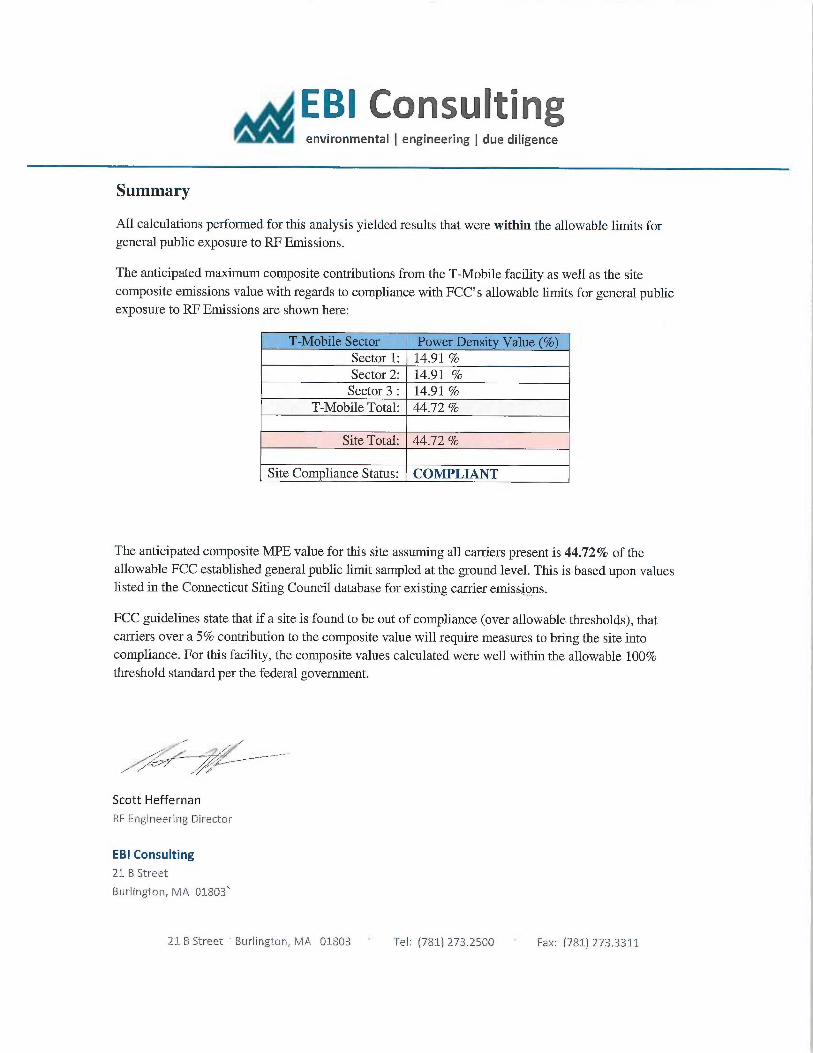
EBI Consulting~, environmental ~ engineering ~ due diligence
Summary
All calculations performed for this analysis yielded results that were within the allowable limits forgeneral public exposure to RF Emissions.
The anticipated ma~mum composite contributions from the T-Mobile facility as well as the sitecomposite emissions value with regards to compliance with FCC's allowable limits for general publicexposure to RF Emissions are shown here:
T-Mobile Sector Power Density Value (%;Sector 1: 14.91 %Sector 2: 14.91 %Sector 3 : 14.91 %
T-Mobile Total: 44.72 %
Site Total: 44.72 %
Site Com fiance Status: COMPLIANT
The anticipated composite MPE value for this site assuming all carriers present is 44.72% of theallowable FCC established general public limit sampled at the ground level. This is based upon valueslisted in the Connecticut Siting Council database for e~sting carrier emissions.
FCC guidelines state that if a site is found to be out of compliance (over allowable thresholds), thatcarriers over a 5% contribution to the composite value will require measures to bring the site intocompliance. For this facility, the composite values calculated were well within the allowable 100%threshold standard per the federal government.
/ v
Scott Heffernan
RF Engineering Director
EBI Consulting
21 B Street
Burlington, NiA 01803
21 B Streei Burlington, MA 01803 Tel: (781) 273.2500 Fax: (781) 273.3311
Related Documents