G2647-90001 Instructions PM of FPD Agilent Technologies, Inc.© 2005 page 1 of 18 G2647-90001, Instructions, PM for FPD During the PM for the Flame Photometric Detector (FPD), you will dismantle the optics, replace the emission chamber, replace the igniter, and replace all of the seals. You may also replace the inert transfer line. Please read the entire procedure before starting. This procedure usually resolves problems with lighting, noise, and contamination. The procedure requires attention to detail and time. • Disassembly and reassembly takes about 1 hour. Use lint free gloves to prevent contamination from skin oils. Always set parts on clean clothes. • We recommend that you run a “benchmark” checkout test before and after to compare the results. The time for one checkout run using Agilent’s checkout sample is about 15- minutes. The procedure is described in FPD Accessory Installation & Operation Guide, G1535-90328. • After reassembly, we recommend a 15-minute bake-out at 250°C. • The detector output takes about 1 hour to stabilize after the bake-out and reestablishing checkout conditions. There are 2 PM kits. You may also replace the transfer line that keeps the sample hot between the column oven and the emission chamber. Replace it if you believe there is a restriction or contamination. Order the following: • For a single FPD, order G2647-60501, FPD PM kit, single. • For a dual FPD, order G2648-60501, FPD PM kit, dual. • For applications with halogenated solvents, order optional stainless steel exhaust tube. See the tools and supplies list for part numbers. • If restriction or contamination, order Transfer line and O-rings for detector EPC module. See the tools and supplies list for part numbers. • It is a good practice to synchronize this PM, inlet maintenance, and compliance services.

Welcome message from author
This document is posted to help you gain knowledge. Please leave a comment to let me know what you think about it! Share it to your friends and learn new things together.
Transcript
G2647-90001 Instructions PM of FPD Agilent Technologies, Inc.© 2005 page 1 of 18
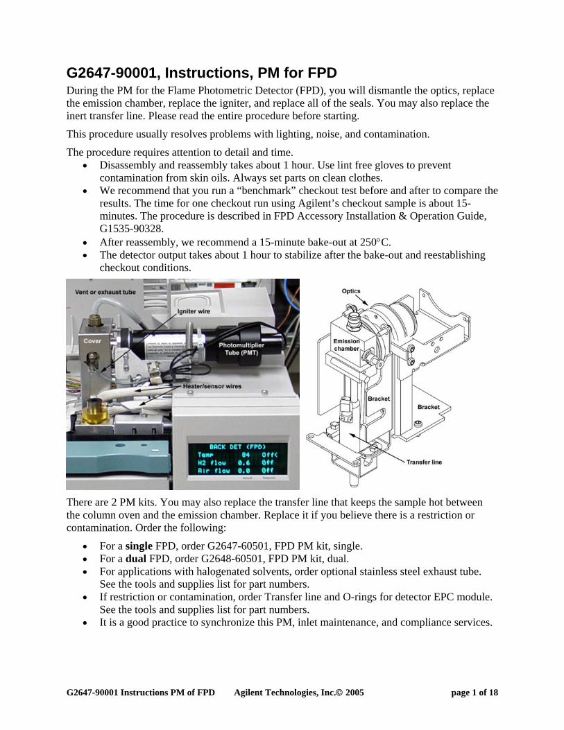
G2647-90001, Instructions, PM for FPD During the PM for the Flame Photometric Detector (FPD), you will dismantle the optics, replace the emission chamber, replace the igniter, and replace all of the seals. You may also replace the inert transfer line. Please read the entire procedure before starting.
This procedure usually resolves problems with lighting, noise, and contamination.
The procedure requires attention to detail and time. • Disassembly and reassembly takes about 1 hour. Use lint free gloves to prevent
contamination from skin oils. Always set parts on clean clothes. • We recommend that you run a “benchmark” checkout test before and after to compare the
results. The time for one checkout run using Agilent’s checkout sample is about 15-minutes. The procedure is described in FPD Accessory Installation & Operation Guide, G1535-90328.
• After reassembly, we recommend a 15-minute bake-out at 250°C. • The detector output takes about 1 hour to stabilize after the bake-out and reestablishing
checkout conditions.
There are 2 PM kits. You may also replace the transfer line that keeps the sample hot between the column oven and the emission chamber. Replace it if you believe there is a restriction or contamination. Order the following:
• For a single FPD, order G2647-60501, FPD PM kit, single. • For a dual FPD, order G2648-60501, FPD PM kit, dual. • For applications with halogenated solvents, order optional stainless steel exhaust tube.
See the tools and supplies list for part numbers. • If restriction or contamination, order Transfer line and O-rings for detector EPC module.
See the tools and supplies list for part numbers. • It is a good practice to synchronize this PM, inlet maintenance, and compliance services.

G2647-90001 Instructions PM of FPD Agilent Technologies, Inc.© 2005 page 2 of 18
This table lists the contents of the 2 PM kits.
Part # Description Single Dual Seal between 0905-1100 O-Ring, Fluorocarbon, Brown 1 2 Lens housing and PMT 0905-0955 O-Ring, Silicone Rust Color 1 2 Coupling and focusing lens 0905-1608 O-Ring, Perfluoroelastomer, White 1 2 Jet and emissions chamber 19256-60700 FPD Exit Tube 1 1 Emissions chamber and vent 19256-60800 FPD igniter replacement kit 1 1 19256-80030 Window, first 1 2 19256-80045 Seal-Heat Shield, White 1 2 Emissions chamber and window 19256-80560 Emission chamber, single 1 0 19256-80600 Emission chamber, dual 0 1 G2647-90001 Instructions, PM for FPD 1 1

G2647-90001 Instructions PM of FPD Agilent Technologies, Inc.© 2005 page 3 of 18
This table lists the tools and supplies that you may need.
Part # Description Used 8710-0510 ¼ x 5/16-inch wrench Remove column, install glow plug 8710-0972 3/8 x 7/16-inch wrench Remove capillary column adapter 19256-80640 Column cutting tool Cut column and swag ferrule 8710-0830 7/16 x 9/16-wrench Remove source gases, remove vent tube 1340407010 7-mm wrench or small adjustable Remove nuts for transfer line. 8710-3465 T-20 torx driver Remove detector cover 8710-3466 T-10 torx driver Remove igniter collar, disassemble optics 8710-2140 T-10 torx key Remove transfer line heater/sensor
8710-0899 No 1 Pozidrive or Philips screwdriver Remove coupling and heat shield disk from emission chamber.
8650-0029 8650-0030
Nylon lint-free gloves, small Nylon lint-free gloves, large Prevent fingerprints and skin oils on parts.
05980-60051 Lint-free clothes 15/pkg Protect filters and optics assembly.
Tweezers, pick, awl, or small flathead driver Remove o-rings from jet and lens holder.
5180-4124 1/8-inch plug, brass 6/pkg Plug base of transfer line 19265-60555 Transfer line, inert Only if you are replacing transfer line 5180-4181 O-rings 12/pkg Only if you are replacing transfer line 19256-20705 Exhaust tube, stainless steel Only if injecting corrosive solvents.
Preparing for PM Warning: Cool down the heated zones of the GC. Shut off the gases. Power OFF the gas chromatograph and disconnect the power cord.
Caution: To prevent damage to the column or columns, remove the columns from the GC.
Additional tasks in preparation, include: • If you are replacing the transfer line turn off the sources gases to the FPD detector. • If you are not replacing the transfer line, plug base of transfer line with a 1/8-inch
Swaglok® nut to keep it clean.

G2647-90001 Instructions PM of FPD Agilent Technologies, Inc.© 2005 page 4 of 18
Disassembling the detector Our objective here is to disassemble the detector and prevent it from getting dirty. We recommend using lint free gloves during most of these steps.
1. Disconnect the spring and remove the photo-multiplier tube (PMT). Place it in a safe place away from the light. The dual will have 2 PMTs.
2. Remove and set aside the filter in a lint free cloth. For sulfur, remove the plastic spacer and then the filter. Try tapping the side of the detector or using the edge of a cotton swab. The phosphorous filter sits closer to the end of the housing.

G2647-90001 Instructions PM of FPD Agilent Technologies, Inc.© 2005 page 5 of 18
3. Remove the vent or exhaust tube with a 9/16-inch wrench.
4. Remove the 4 screws and detector cover with a torx T-20 driver.

G2647-90001 Instructions PM of FPD Agilent Technologies, Inc.© 2005 page 6 of 18
5. Loosen one screw and remove the igniter collar with a torx T-10 driver. The collar of your igniter may have 1 or 2 screws.
6. Remove the heater/sensor assembly from the emission block.
The heater/sensor assembly for the dual attaches with a screw.
7. Remove one screw and retainer for the heater/sensor assembly in the transfer line with a
torx T-10 Key.

G2647-90001 Instructions PM of FPD Agilent Technologies, Inc.© 2005 page 7 of 18
8. Remove the heater/sensor assembly. 9. Move the heater/sensor assemblies and igniter cable to the front of the oven top.
10. Remove two 7-mm mounting nuts from the base of the transfer line.
11. Loosen 3 screws that hold the optics assembly to the detector bracket with a torx T-10 driver.

G2647-90001 Instructions PM of FPD Agilent Technologies, Inc.© 2005 page 8 of 18
12. The objective of this step is to separate the optics from the transfer line. Do not flex the tubing where it is brazed to the transfer line weldment. Grasp the transfer line with your left hand and the optics assembly with your right hand. Lift them just high enough for the 3 screws that you loosened in step 11 are above the bracket.
13. Twist and lift the optics while holding the transfer line stationary. Carefully, separate the assemblies. The o-ring on the transfer jet is compressed against the inside of the emissions chamber. This is the resistance that you feel.
14. Place the optic assembly onto a lint free cloth.
15. If you are not replacing the transfer line, skip to the section Rebuilding the optics assembly. If you are replacing the transfer line, continue on with the next section.

G2647-90001 Instructions PM of FPD Agilent Technologies, Inc.© 2005 page 9 of 18
Replacing the transfer line This section describes replacing the transfer line. Use lint-free gloves when handling the transfer line body and o-ring seals.
16. Remove the hinged detector cover and 2 covers over the EPC modules. Use a T-20 torx driver to remove the sheet metal cover.
17. Note the routing of the gas lines from the base of the detector back to the gang fitting.

G2647-90001 Instructions PM of FPD Agilent Technologies, Inc.© 2005 page 10 of 18
18. Carefully lift the transfer line out of the bracket. 19. Lift the tubing out of the notches.
20. Disconnect the gang fitting from the detector EPC module.
21. Replace the 3 o-rings in the EPC module to insure against leaks. 22. Route the gang fitting of the new transfer line through the hole in the back cover and
connect it to the EPC module. 23. Lower the new transfer line into the bracket. Do not fasten to the bracket. 24. Route the gas lines from the back of the transfer line through the 2 notches. Bend the
tubing into a loop to fit under the covers. 25. Replace the covers.

G2647-90001 Instructions PM of FPD Agilent Technologies, Inc.© 2005 page 11 of 18
Rebuilding the optics assembly Use lint-free gloves when handling the optics assembly and o-ring seal.
26. Completely loosen the 4 T-10 screws from the clamp and coupling with the T-10 driver.
27. Set the Y-shaped clamp to one side. 28. Carefully separate the lens housing from the stainless steel coupling. The focusing lens
and o-ring usually stick to the coupling, but could stay with the lens housing. Try to keep the housing, flange ring, screws and washers in place.
G2647-90001 Instructions PM of FPD Agilent Technologies, Inc.© 2005 page 12 of 18
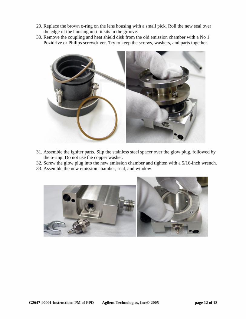
29. Replace the brown o-ring on the lens housing with a small pick. Roll the new seal over the edge of the housing until it sits in the groove.
30. Remove the coupling and heat shield disk from the old emission chamber with a No 1 Pozidrive or Philips screwdriver. Try to keep the screws, washers, and parts together.
31. Assemble the igniter parts. Slip the stainless steel spacer over the glow plug, followed by the o-ring. Do not use the copper washer.
32. Screw the glow plug into the new emission chamber and tighten with a 5/16-inch wrench. 33. Assemble the new emission chamber, seal, and window.
G2647-90001 Instructions PM of FPD Agilent Technologies, Inc.© 2005 page 13 of 18
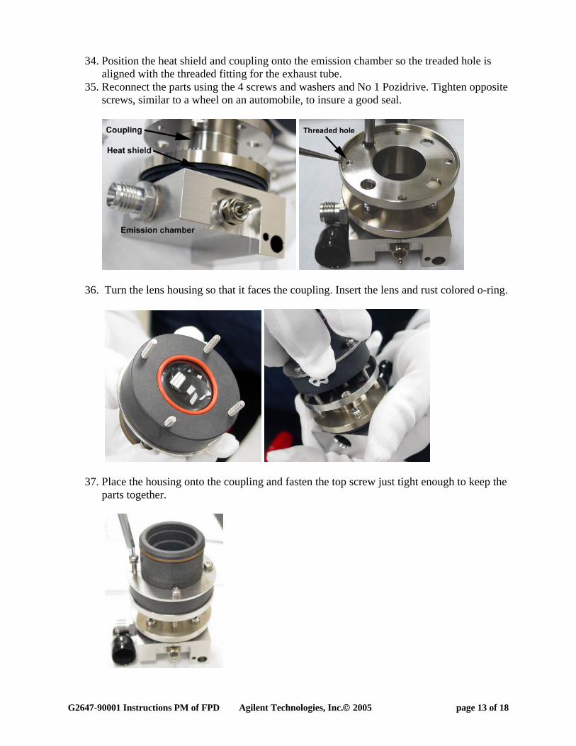
34. Position the heat shield and coupling onto the emission chamber so the treaded hole is aligned with the threaded fitting for the exhaust tube.
35. Reconnect the parts using the 4 screws and washers and No 1 Pozidrive. Tighten opposite screws, similar to a wheel on an automobile, to insure a good seal.
36. Turn the lens housing so that it faces the coupling. Insert the lens and rust colored o-ring.
37. Place the housing onto the coupling and fasten the top screw just tight enough to keep the parts together.

G2647-90001 Instructions PM of FPD Agilent Technologies, Inc.© 2005 page 14 of 18
38. Hold the y-shaped clamp and start the remaining screws into the clamp. Do not tighten until step 45.
Reassembling the detector This part of the procedure reassembles the optics assembly with the transfer line, reconnects both to the detector bracket, replaces the heater/sensor and igniter wires, replaces the covers and PMT.
39. Replace or install the o-ring on the transfer line jet. Remove the o-ring with a small pick. Place the new o-ring over the jet. Roll it into the groove below the jet.

G2647-90001 Instructions PM of FPD Agilent Technologies, Inc.© 2005 page 15 of 18
40. Reposition the detector optics above the bracket. 41. The objective of this step is to reattach the optics to the transfer line and insure a good
seal between the o-ring and the emissions chamber. Grasp the transfer line with your left hand and the optics assembly with your right hand. Push them together while twisting back and forth.
42. Before lowering the assemblies into the bracket, make sure there is no gap between the transfer line and the emission chamber.
43. Lower the assemblies into the bracket. Line up the holes in the transfer line base with the threaded posts in the bracket. Line up the 3 screws and the clamp with the notches in the detector bracket.

G2647-90001 Instructions PM of FPD Agilent Technologies, Inc.© 2005 page 16 of 18
44. Reattach the transfer line to the bracket with the 7-mm nuts. 45. Tighten the clamp against the detector bracket. Tighten the 3 bottom screws on the optics
assembly. 46. Insert the heater/sensor assembly into the transfer line. Make sure the sensor is at the
bottom of the hole. 47. Reinstall the retainer and screw.
48. Insert the heater/sensor assembly into the emission chamber. 49. Reconnect the igniter wire to the glow plug.
G2647-90001 Instructions PM of FPD Agilent Technologies, Inc.© 2005 page 17 of 18
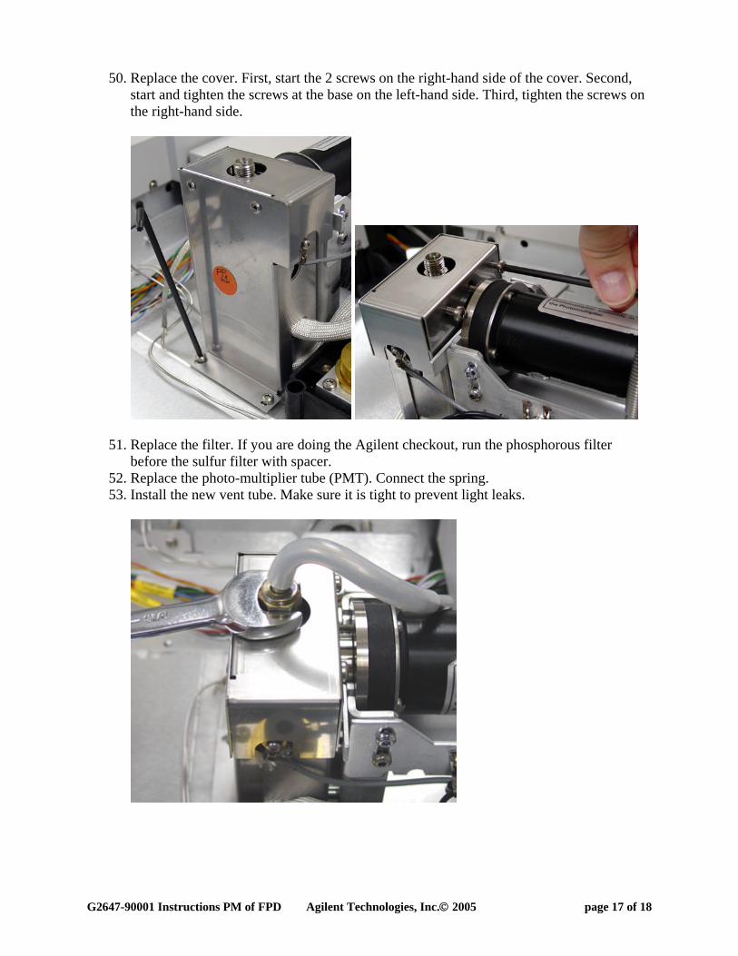
50. Replace the cover. First, start the 2 screws on the right-hand side of the cover. Second, start and tighten the screws at the base on the left-hand side. Third, tighten the screws on the right-hand side.
51. Replace the filter. If you are doing the Agilent checkout, run the phosphorous filter before the sulfur filter with spacer.
52. Replace the photo-multiplier tube (PMT). Connect the spring. 53. Install the new vent tube. Make sure it is tight to prevent light leaks.
G2647-90001 Instructions PM of FPD Agilent Technologies, Inc.© 2005 page 18 of 18
Bake out and run checkout test This part of the procedure bakes out the detector and restores conditions. The detector output will level off in about 1 hour after you restore the conditions. The detector output will continue to drift down slowly for about 24 hours.
54. Reinstall the column or columns. 55. Reinstall the drain tube to the FPD exhaust tube. 56. Restore the gases to the GC. 57. Restore the power to the GC. 58. Restore the conditions to the inlets and detectors, but turn off the flame of the FPD to
prevent condensation. 59. After the FPD is at temperature for about 10-minutes, light the flame. 60. Bake out the detector. Set the oven and detector temperatures to 250C for 15 minutes.
Insure there is adequate gas flows through the column. 61. After the bake out, restore the oven and FPD conditions. 62. Allow the output to level off. 63. Run a checkout and compare the results.
Related Documents