DESIGN AND DEVELOPMENT OF A PIPE INSPECTION ROBOT MUHAMMAD AZRI BIN ABDUL WAHED UNIVERSITI SAINS MALAYSIA 2015

Fyp Thesis sem
Dec 04, 2015
sem thesis
Welcome message from author
This document is posted to help you gain knowledge. Please leave a comment to let me know what you think about it! Share it to your friends and learn new things together.
Transcript
DESIGN AND DEVELOPMENT OF A PIPE INSPECTION
ROBOT
MUHAMMAD AZRI BIN ABDUL WAHED
UNIVERSITI SAINS MALAYSIA
2015
DESIGN AND DEVELOPMENT OF A PIPE INSPECTION
ROBOT
by
MUHAMMAD AZRI BIN ABDUL WAHED
Thesis submitted in partial fulfillment of the
requirements for the degree of
Bachelor of Engineering (Electronic Engineering)
JUNE 2015

ii
ACKNOWLEDGEMENTS
I am grateful to God for the good health and wellbeing that were necessary to
complete this final year project. There are many people that deserve mentions and
thankfulness for their help, guidance and support during the duration of this project. It is
impossible for me to complete this dissertation without them.
I wish to express my sincere thanks to my final year project supervisor, Prof. Dr
Mohd Rizal Arshad, Deputy Dean of School of Electrical and Electronic Engineering
USM for providing me with all the necessary means and facilities to complete my project.
Dr. Rizal had provide me with a clear concept on my project which leads to the
successfulness of my project. His patience in guiding me to come out with a good thesis
is very much appreciated.
Besides, my sincere thank you to Mr. Muhammad Faiz bin Abu Bakar, Research
Assistant for Underwater, Control, and Robotics Group (UCRG). He had provide me
with assistant throughout the duration of this project. He had assisted me in developing
the graphical user interface for my final year project. Mr .Faiz also contributed a lot
during the testing of my project.
Many thanks go to Mr. Hafiez Mokhtar and Mr. Muhammad Azwan. Mr. Hafiez
had helped me in resourcing of material and checking of my design while Mr. Azwan
had helped me in understanding the theory for the embedded system development.
I would also like to take this opportunity to express gratitude to all the member
of Underwater Robotics Research Group for their help and support. I also thank my
parent for the unlimited encouragement, support and attention.
Last but not least, my sense of gratitude to one and all, who directly or indirectly,
have lent their hand in this project.

iii
TABLE OF CONTENTS
Acknowledgements ii
Table of Contents iii
List of Tables vii
List of Figures viii
List of Abbreviations xii
Abstrak xiii
Abstract xiv
CHAPTER 1 - INTRODUCTION 1
1.1 Background 1
1.2 Motivations 2
1.3 Problem Statements 3
1.4 Objectives 3
1.5 Scope 4
1.6 Outlines of Report 4
CHAPTER 2 – LITERATURE REVIEW 6
2.1 Introduction 6
2.2 Wheel type 7
2.2.1 Direct drive 7
2.2.2 Differential drive 7
2.2.3 Tractive vehicles 8
2.3 Caterpillar type 8
2.3.1 LS-01 9
iv
2.4 Wall-press type 9
2.4.1 MRINSPECT III 10
2.4.2 MRINSPECT IV 10
2.5 Walking type 11
2.6 Inchworm type 12
2.6.1 MARK IV 12
2.6.2 Pneumatic line based inchworm type 13
2.7 Screw type 14
2.8 Electro-magnetic force type 15
2.9 Comparison of pipe inspection robots 15
2.10 Components required 16
2.11 Summary 17
CHAPTER 3 - METHODOLOGY 18
3.1 Introduction 18
3.2 Flow Chart 18
3.3 Design Specification 20
3.4 Project Requirements Selections 22
3.4.1 Arduino Micro ATmega32u4 22
3.4.2 Motor Driver 23
3.4.2.1 L293D and 74HC595 23
3.4.3 DC Micro Metal Gear Motor 45 rpm 25
3.4.4 DC Geared Motor SPG30-60K 26
3.4.5 Micro Servo Motor MG90s 26
3.4.6 Camera JK-801 27
3.5 Mechanical System Development 28

v
3.5.1 3D Modeling Using SolidWorks 28
3.5.2 Fabrication 32
3.5.2(a) Camera Enclosure 34
3.5.2(b) Driving Module 35
3.5.2(c) Electronic Compartment 36
3.6 Embedded System Development 38
3.6.1 Driving Module 39
3.6.2 Camera Pan and Tilt 44
3.6.3 Graphical User Interface 46
3.7 Testing 49
3.7.1 Drivability Test 49
3.7.2 Camera viewing Vision 52
3.8 Performance Evaluation 52
3.9 Summary 52
CHAPTER 4 – RESULTs AND DISCUSSIONs 53
4.1 Introduction 53
4.2 Result of Mechanical System Development 53
4.3 Result of Embedded System Development 56
4.3.1 Driving Module 57
4.3.2 Camera Pan and Tilt 57
4.3.3 Graphical User Interface 59
4.4 Testing Results 60
4.4.1 Drivability Result 60
4.4.2 Camera Viewing Vision 65
4.5 Real Time Performance Evaluation 66

vi
4.7 Summary 68
CHAPTER 5 – CONCLUSION & FUTURE WORK 69
5.1 Conclusion 69
5.2 Future Works 70
REFERENCES 71
vii
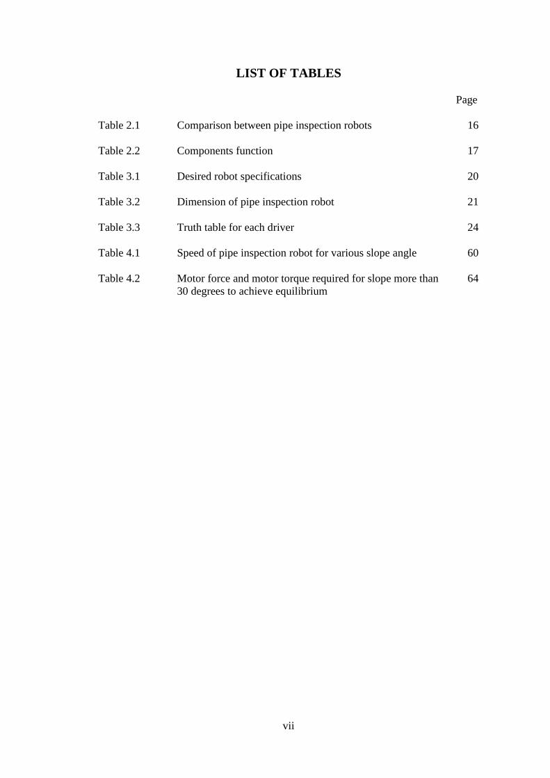
LIST OF TABLES
Page
Table 2.1 Comparison between pipe inspection robots 16
Table 2.2 Components function 17
Table 3.1 Desired robot specifications 20
Table 3.2 Dimension of pipe inspection robot 21
Table 3.3 Truth table for each driver 24
Table 4.1 Speed of pipe inspection robot for various slope angle 60
Table 4.2 Motor force and motor torque required for slope more than
30 degrees to achieve equilibrium
64
viii
LIST OF FIGURES
Page
Figure 2.1 Classification of pipe inspection robots
(a) Pig type
(b) Wheel type
(c) Caterpillar type
(d) Wall-press type
(e) Walking type
(f) Inchworm type
(g) Screw type
6
Figure 2.2 Wheels independently connected to motor 7
Figure 2.3 Differential drive 7
Figure 2.4 Plain structures of tractive vehicles 8
Figure 2.5 LS-01 prototype model 9
Figure 2.6 MRINSPECT III 10
Figure 2.7 MRINSPECT IV 11
Figure 2.8 Tube-crawler 12
Figure 2.9 MARK IV basic structure 12
Figure 2.10 Pneumatic inchworm working principle 13
Figure 2.11 Screw principle robot design 14
Figure 3.1 Research methodology flow chart 19
Figure 3.2 Arduino Micro Atmega32u4 front view 23
Figure 3.3 L293D block diagram 24
Figure 3.4 L293D pin configuration 25

ix
Figure 3.5 74HC595 pin configuration 25
Figure 3.6 DC micro metal gear motor 26
Figure 3.7 SPG30-60K 26
Figure 3.8 Micro servo motor MG90s 27
Figure 3.9 Mini CMOS CCTV camera JK-801 27
Figure 3.10 Schematic drawing of the total length of the robot 28
Figure 3.11 Schematic drawing of the maximum robot diameter 29
Figure 3.12 Schematic drawing for the front section 29
Figure 3.13 Schematic drawing for the driving module 30
Figure 3.14 Schematic drawing for the camera pan and tilt mechanism 30
Figure 3.15 Schematic drawing for the universal joint 31
Figure 3.16 External frame drawing 32
Figure 3.17 Internal frame drawing 33
Figure 3.18 Driving module 33
Figure 3.19 Base top view 34
Figure 3.20 Cage top view 34
Figure 3.21 Assembly of camera and servo motors 35
Figure 3.22 Driving module arm 36
Figure 3.23 DC motor inside electronic compartment 37
Figure 3.24 Threaded rod for expansion and contraction 37
Figure 3.25 Block diagram for embedded system 38
Figure 3.26 Connection between shift register and motor driver for front
driving module
39
Figure 3.27 Connection between shift register and motor driver for back
driving module
40

x
Figure 3.28 Connection from shift register to Arduino 41
Figure 3.29 Flow chart of programming code for receiving serial data
from PC and transmitting it to motor driver
42
Figure 3.30 Circuit constructed on strip board 43
Figure 3.31 LM2596 switching voltage regulator 43
Figure 3.32 Various PWM duty cycle 44
Figure 3.33 Connection between Arduino and micro servo motor 45
Figure 3.34 Flow chart for servo programming 46
Figure 3.35 Layout of the graphical user interface 47
Figure 3.36 Flow chart for graphical user interface 48
Figure 3.37 Setting up of testing ground 50
Figure 3.38 Angle calibration with smartphone level balance 51
Figure 4.1 Completed pipe inspection robot 54
Figure 4.2 (a) Top view
(b) Side vied
(c) Process of inserting the electronics into the electronic
compartment
55
Figure 4.3 (a) Long threads used to combine driving module with
electronics compartment
(b) screw used to hold motor in place
55
Figure 4.4 (a) Wiring from front to back section
(b) Motor wiring passing through a tube
(c) Power and signal wire wrapped with cable wrapper
56
Figure 4.5 (a) Camera view rotated 90° to the left
(b) Camera view at 0°
58

xi
(c) Camera view rotated 90° to the right
Figure 4.6 (a) Camera rotated 90° upwards
(b) Camera at horizontal position
(c) Camera at rotated 90° downwards
59
Figure 4.7 Graph of speed (m/s) against slope angle, Ɵ (°) with 100%
duty cycle
61
Figure 4.8 Pipe inspection robot successfully climbing inside the pipe
at 10° gradient
62
Figure 4.9 Position of robot at Ɵ degree angle
63
Figure 4.10 Comparison of the ambient light without and with the usage
of LED
65
Figure 4.11 Comparison of the actual images taken by the CCTV
camera without and with the usage of LED
66
Figure 4.12 Servo maximum angle rotation 66
Figure 4.13 (a) Robot starting at one end of the pipe
(b) Robot end at the other end of the pipe
67
Figure 4.14 (a) Robot in a smaller diameter configuration
(b) Robot in larger diameter configuration
67
xii
LIST OF ABBREVIATION
ABS Acrylonitrile Butadiene Styrene
CAD Computer-aided design
CCTV Closed-circuit Television
CMOS Complementary Metal-oxide-semiconductor
DAUJ Double Active Universal Joint
DC Direct Current
DOF Degree of Freedom
GUI Graphical Image Processing
IC Integrated Circuit
ICSP In-Circuit Serial Programming
LED Light Emitting Diode
LSB Least Significant Bit
MSB Most Significant Bit
PC Personal Computer
PLA Polylactic Acid
PVC Polyvinyl Chloride
PWM Pulse Width Modulation
SMA Shape Memory Alloy
STL Stereolithographgy
USB Universal Serial Bus
VCC IC Power Supply Pin
Vdc Volts of Direct Current
xiii
Rekabentuk dan Pembangunan Robot Pemeriksaan Paip
ABSTRAK
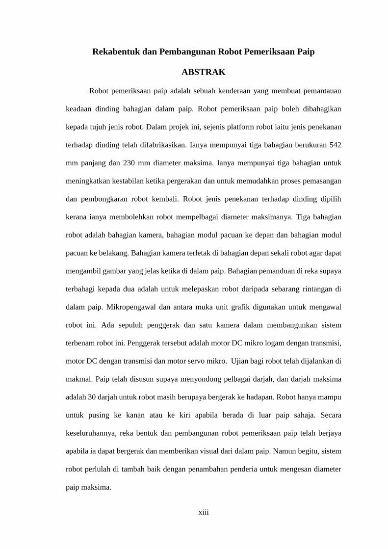
Robot pemeriksaan paip adalah sebuah kenderaan yang membuat pemantauan
keadaan dinding bahagian dalam paip. Robot pemeriksaan paip boleh dibahagikan
kepada tujuh jenis robot. Dalam projek ini, sejenis platform robot iaitu jenis penekanan
terhadap dinding telah difabrikasikan. Ianya mempunyai tiga bahagian berukuran 542
mm panjang dan 230 mm diameter maksima. Ianya mempunyai tiga bahagian untuk
meningkatkan kestabilan ketika pergerakan dan untuk memudahkan proses pemasangan
dan pembongkaran robot kembali. Robot jenis penekanan terhadap dinding dipilih
kerana ianya membolehkan robot mempelbagai diameter maksimanya. Tiga bahagian
robot adalah bahagian kamera, bahagian modul pacuan ke depan dan bahagian modul
pacuan ke belakang. Bahagian kamera terletak di bahagian depan sekali robot agar dapat
mengambil gambar yang jelas ketika di dalam paip. Bahagian pemanduan di reka supaya
terbahagi kepada dua adalah untuk melepaskan robot daripada sebarang rintangan di
dalam paip. Mikropengawal dan antara muka unit grafik digunakan untuk mengawal
robot ini. Ada sepuluh penggerak dan satu kamera dalam membangunkan sistem
terbenam robot ini. Penggerak tersebut adalah motor DC mikro logam dengan transmisi,
motor DC dengan transmisi dan motor servo mikro. Ujian bagi robot telah dijalankan di
makmal. Paip telah disusun supaya menyondong pelbagai darjah, dan darjah maksima
adalah 30 darjah untuk robot masih berupaya bergerak ke hadapan. Robot hanya mampu
untuk pusing ke kanan atau ke kiri apabila berada di luar paip sahaja. Secara
keseluruhannya, reka bentuk dan pembangunan robot pemeriksaan paip telah berjaya
apabila ia dapat bergerak dan memberikan visual dari dalam paip. Namun begitu, sistem
robot perlulah di tambah baik dengan penambahan penderia untuk mengesan diameter
paip maksima.
xiv
Design and Development of a Pipe Inspection Robot
ABSTRACT
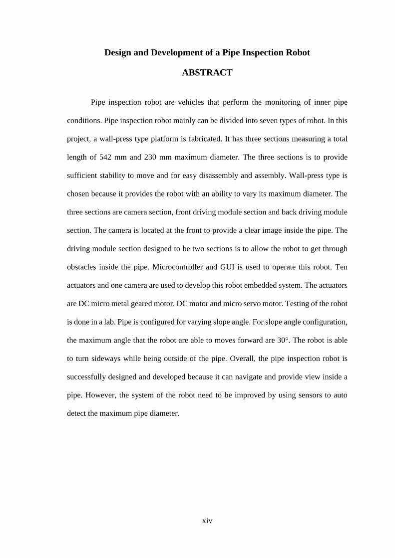
Pipe inspection robot are vehicles that perform the monitoring of inner pipe
conditions. Pipe inspection robot mainly can be divided into seven types of robot. In this
project, a wall-press type platform is fabricated. It has three sections measuring a total
length of 542 mm and 230 mm maximum diameter. The three sections is to provide
sufficient stability to move and for easy disassembly and assembly. Wall-press type is
chosen because it provides the robot with an ability to vary its maximum diameter. The
three sections are camera section, front driving module section and back driving module
section. The camera is located at the front to provide a clear image inside the pipe. The
driving module section designed to be two sections is to allow the robot to get through
obstacles inside the pipe. Microcontroller and GUI is used to operate this robot. Ten
actuators and one camera are used to develop this robot embedded system. The actuators
are DC micro metal geared motor, DC motor and micro servo motor. Testing of the robot
is done in a lab. Pipe is configured for varying slope angle. For slope angle configuration,
the maximum angle that the robot are able to moves forward are 30°. The robot is able
to turn sideways while being outside of the pipe. Overall, the pipe inspection robot is
successfully designed and developed because it can navigate and provide view inside a
pipe. However, the system of the robot need to be improved by using sensors to auto
detect the maximum pipe diameter.
1
CHAPTER 1
INTRODUCTION
1.1 Background
In west Malaysia alone, the length of sewerage pipe has exceeded 15000 km.
With such length, monitoring and maintenance are not easy tasks. There are also other
pipelines in used for other purposes such as urban gas, chemical plant and chemical plant
which is mostly used by developed nations. Pipelines are a means of transporting oil and
gas for a very long time. Years of usage will bring it to aging, corrosion, developed cracks
and mechanical damages. This is why inspection, maintenance and repair need to be
done. However, this continuous activities requires enormous amount of budgets. Thus, a
low cost robot suited for multiple pipe dimension along with integrated maintenance
program need to be designed.
Wheel type system is the most popular system for pipe inspection robot because
it has the fastest speed among other types. Because all of its wheel is in contact with the
inner pipe surfaces, they have more grip than other types. They also has high torque and
carry large payload. However, due to the design they are usually not used in very small
pipe diameter. There are many types of wheeled pipe inspection vehicles already being
developed and used. Examples of them are LS-01 [1].
Wall-press type is a system that has becoming more popular for performing pipe
inspections tasks. They are nominally design for 10 inches pipe diameter [2]. The driving
modules adjust the whole robot dimension to fit exactly into the pipe. They produce
enough grip and torque to even be able to climb a pipe vertically. The steering motion is
done by varying the speed of each of its driving module. Examples of wall-press type
robot is MRINSPECT III and MRINSPECT IV [3].

2
1.2 Motivations
The varying size of pipe diameter used in pipelines requires multiple robots to
perform pipe inspection tasks. However, having multiples pipe inspection robots will
increase operating and maintenance costs. On the other hand, having a wall-press robot
that can inspect various diameter of pipe will reduce overall costs. Importance of a wall-
press type lies on the fact that it is able to climb steep pipe and also fit in various diameter
of pipe with a single robot.
Pipe inspection task is an important task in maintaining the condition of pipelines
used for sewerage, transporting oils and gas and other liquids. Operations by human,
autonomous vehicles and remotely operate vehicle required high costs, introduce high
risk and required dedicated surface support. Therefore, it is wise to reduce overall costs
wherever possible. Usage of wall-press type has an outstanding mobility and able to
comply with complicated pipe geometries [4]. This robot can fit various pipe dimension
and inspect pipe conditions in a cost-effective manner compare to having multiple robots
for various pipe dimensions.
Furthermore, pipe inspection robot is a helpful vehicles for maintaining pipe
condition. For example, wheel typed robot can be fit in with various sensors to detect
possible gas leakage in pipe. A robot equipped with necessary tools to perform welding
task can also fix minor leakage inside the pipe. Robot fixed with laser can be used to
detect pipe surface anomaly [5]. Since pipe inspection robot are becoming more popular
as the main method for pipe inspection tasks, more technologies will be developed and
this will increase the competition. As competition increases, prices will decline and non-
destructive inspection will come justified even for pipes with relatively moderate
consequences of failure [6].
3
1.3 Problem Statements
To develop a pipe inspection robot that able to perform pipe inspection task, it
must be able to overcome various pipe dimension and conditions. The most basic ability
of pipe inspection robot is to view the conditions of inner pipe. Among the information
needed to be gathered are the pipe inner conditions, angle of the robot, speed of the robot
and distance travelled by the robot. With this information, a thorough pipe inspection can
be performed.
For angled pipelines, the robot needs to be able to climb without slipping. A more
angled pipelines will be more difficult for the robot to climb. The grip and torque required
will be provided by its driving module.
For pipe with obstacles, it should be able to overcome this by reducing its overall
size to move more freely inside the pipe. A camera is needed to detect inner pipe
condition so that the vehicles can do the necessary adjustments.
Furthermore, camera controller and electronic speed controller need to be
developed. Camera provide views inside the pipe, whereas speed controller adjust robot
size, speed and directions.
1.4 Objectives
The objectives of this project are:
1. To design, develop and fabricate pipe inspection robot platform.
2. To develop working programs to remotely control the robot operation.
3. To test the pipe inspection robot system for simple pipe inspection application.
4
To develop the pipe inspection robot, all of the components operation is studied
and tested carefully before being installed into the waterproof body and modules. To
develop a program for pipe inspection, servo motor will be controlled by the Arduino
board to control the pan and tilt of the camera. Sensors is used to return values while
inside the pipe for program to act accordingly. Various tests need to be carried out to test
the effectiveness of pipe inspection robot for simple pipe inspection application.
1.5 Scope
This project is focusing mainly on developing a pipe inspection robot. This robot
will be able to perform a simple operations at a suitable speed and has some maneuvering
ability. It is built primarily for operation in 200 mm pipe diameter. This means that, this
pipe inspection robot will work best in a 200 mm pipe diameter.
Arduino is used as the main control unit for this pipe inspection robot. DC geared
micro motor, DC geared motor and servo motor are used as the system actuators. DC
motors is used for driving modules and robot’s size expansion. Servo motor is used to
adjust the viewing of the robot.
In order to develop a reliable program for the robot, system programming is
developed in several parts and its electronic circuit is carefully planned and constructed.
1.6 Outlines of Report
This report contains five chapters. The first chapters is an introduction chapter
which discussed the background of pipe inspection robot, motivation to develop pipe
inspection robot, problem statement, objectives of this project, scope and outlines of the
report.
5
The second chapter is literature review. For this chapter, outcomes from
researching on the scope of the project is covered to give and overview of what is
available and the latest technology available in pipe inspection robot design. Besides that,
theory relevant for pipe inspection robot is also included.
Next, third chapter describes the methodology for pipe inspection robot
development. All steps involved are recorded and explained in detail in this chapter. In
this chapter also, all the mechanical drawing and circuit design of hardware are also
stated. Finally, this chapter discusses the method used to measure the performance of this
pipe inspection robot.
In the fourth chapter, all the experiment results are analyzed and the performance
of the robot are discussed. Furthermore, simulation results are also recorded.
The final chapter contains the conclusion in regard to this project. Last but not
least, suggestion for future research are also included within this chapter.
6
CHAPTER 2
LITERATURE REVIEW
2.1 Introduction
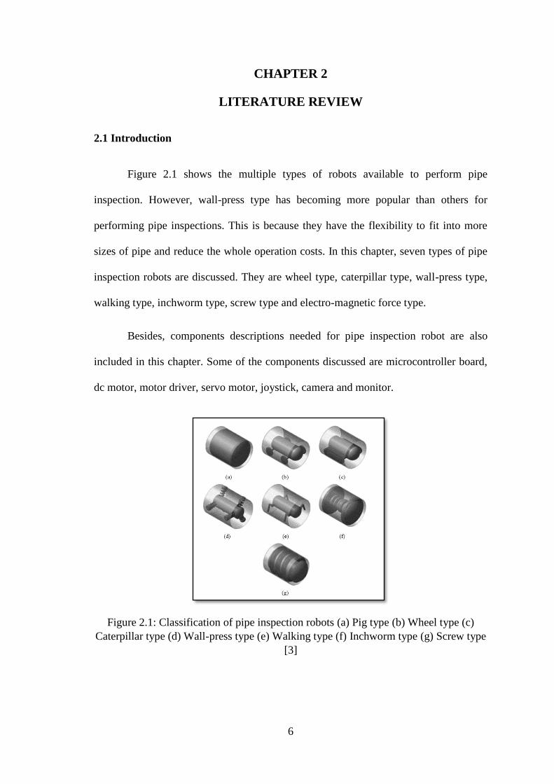
Figure 2.1 shows the multiple types of robots available to perform pipe
inspection. However, wall-press type has becoming more popular than others for
performing pipe inspections. This is because they have the flexibility to fit into more
sizes of pipe and reduce the whole operation costs. In this chapter, seven types of pipe
inspection robots are discussed. They are wheel type, caterpillar type, wall-press type,
walking type, inchworm type, screw type and electro-magnetic force type.
Besides, components descriptions needed for pipe inspection robot are also
included in this chapter. Some of the components discussed are microcontroller board,
dc motor, motor driver, servo motor, joystick, camera and monitor.
Figure 2.1: Classification of pipe inspection robots (a) Pig type (b) Wheel type (c)
Caterpillar type (d) Wall-press type (e) Walking type (f) Inchworm type (g) Screw type
[3]

7
2.2 Wheel type
Wheel type robot typically have at least 4 set of wheel. Each wheels can be driven
independently or through differential drive.
2.2.1 Direct drive
The turning motion is controlled by changing the direction of all the motors.
Because each wheels is connected to its own motor, this configuration will have the
highest total torque available. Thus, more load can be pulled or carried with this setup.
This configuration required a motor each for its wheel as shown in Figure 2.2.
Figure 2.2: Wheels independently connected to motor [7]
2.2.2 Differential drive
Differential drive configuration shown in Figure 2.3 allows usage of less amount
of motor. However, the torque available will also be lower.
Figure 2.3: Differential drive [8]
8
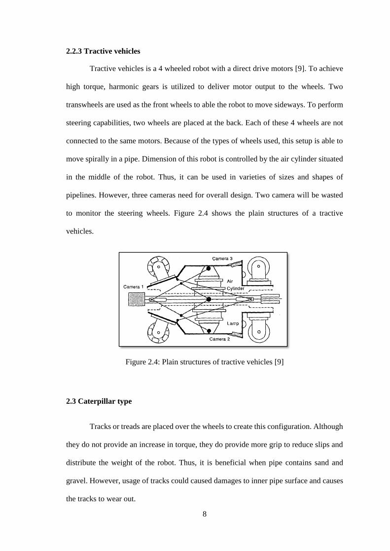
2.2.3 Tractive vehicles
Tractive vehicles is a 4 wheeled robot with a direct drive motors [9]. To achieve
high torque, harmonic gears is utilized to deliver motor output to the wheels. Two
transwheels are used as the front wheels to able the robot to move sideways. To perform
steering capabilities, two wheels are placed at the back. Each of these 4 wheels are not
connected to the same motors. Because of the types of wheels used, this setup is able to
move spirally in a pipe. Dimension of this robot is controlled by the air cylinder situated
in the middle of the robot. Thus, it can be used in varieties of sizes and shapes of
pipelines. However, three cameras need for overall design. Two camera will be wasted
to monitor the steering wheels. Figure 2.4 shows the plain structures of a tractive
vehicles.
Figure 2.4: Plain structures of tractive vehicles [9]
2.3 Caterpillar type
Tracks or treads are placed over the wheels to create this configuration. Although
they do not provide an increase in torque, they do provide more grip to reduce slips and
distribute the weight of the robot. Thus, it is beneficial when pipe contains sand and
gravel. However, usage of tracks could caused damages to inner pipe surface and causes
the tracks to wear out.

9
2.3.1 LS-01
Figure 2.5 is a LS-01 prototype model which is a 4 wheeled type with tracks over
the wheels.
Figure 2.5: LS-01 prototype model [1]
This robot has a foldable top platform acting as camera holder. Standard
differential drive system is used to obtain more grip. The visual feed is captured by a
camera and transmitted to outside view through a visual feed cable. DC brushless motor
used as the actuator along with encoder, gearing system and motion controller.
Fabrication of this robot requires aluminum 6061 for its low density, good strength-to-
weight ratio, corrosion resistance and reasonable costs.
2.4 Wall-press type
Wall-press type robot are most widely used in today pipe inspection robot
configuration. This configuration allows free movement along the basic configuration of
pipelines, both horizontal and vertical. This setup also allows the robot to travel along
reducers, elbows and provide steering mechanisms. Most referenced design is
MRINSPECT (Multifunctional Robotic Crawler for INpipe inSPECTion).
10
2.4.1 MRINSPECT III
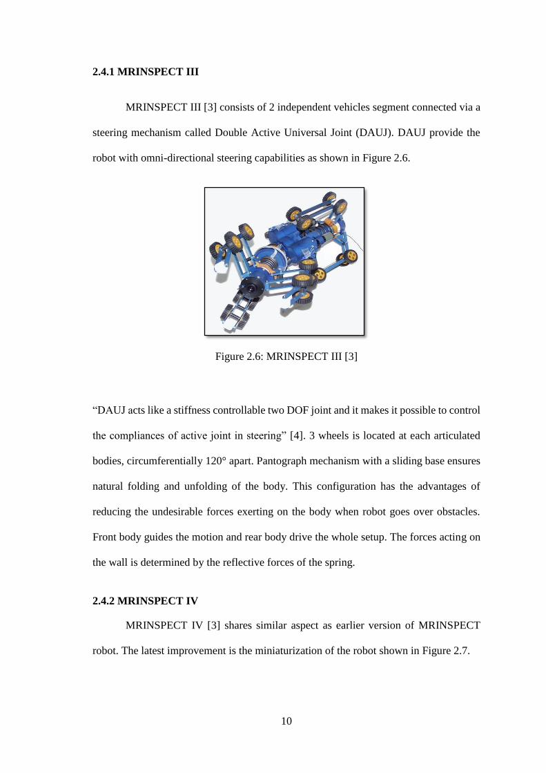
MRINSPECT III [3] consists of 2 independent vehicles segment connected via a
steering mechanism called Double Active Universal Joint (DAUJ). DAUJ provide the
robot with omni-directional steering capabilities as shown in Figure 2.6.
Figure 2.6: MRINSPECT III [3]
“DAUJ acts like a stiffness controllable two DOF joint and it makes it possible to control
the compliances of active joint in steering” [4]. 3 wheels is located at each articulated
bodies, circumferentially 120° apart. Pantograph mechanism with a sliding base ensures
natural folding and unfolding of the body. This configuration has the advantages of
reducing the undesirable forces exerting on the body when robot goes over obstacles.
Front body guides the motion and rear body drive the whole setup. The forces acting on
the wall is determined by the reflective forces of the spring.
2.4.2 MRINSPECT IV
MRINSPECT IV [3] shares similar aspect as earlier version of MRINSPECT
robot. The latest improvement is the miniaturization of the robot shown in Figure 2.7.

11
Figure 2.7: MRINSPECT IV [3]
The new improved design has a body frame that mounts a camera assembly and driving
modules. Each driving modules has a foldable linkage and located circumferentially 120°
apart. Driving module is powered by dc motor with encoder and reducer. Each driving
module is controlled independently. Therefore, tractive force is amplified and providing
the robot its steering capability. The motion of robot is controlled by controlling the speed
differences of each driving module. With differences in driving module speed, thus able
to steers its own body.
2.5 Walking type
Figure 2.8 shows a walking type robot often referred as crawler robot [10] or
tube-crawler robot. This type normally has eight identical two-links legs attached to a
body by a revolute joint or hip joints. All the leg links are rigid rod connected by revolute
joints or knee joints. The advantage of walking type robot is the ability to move around
almost any surface, obstacles and complex shaped hollows. Disadvantages however, it
requires more energy to operate the robot and has a complex controller.

12
Figure 2.8: Tube-crawler [10]
2.6 Inchworm type
This type of robot imitate the movement of inchworm. The movement however
is usually very slow. But, it is possible to design a robot that can fit very small pipe
diameter.
2.6.1 MARK IV
MARK IV [11] is designed to inspect pipe conditions from the outside surface of
the pipe. Its basic structures consists of three major components. The first component is
its flexible arm which has 7 links and 6 joints shown in Figure 2.9.
Figure 2.9: MARK IV basic structure [11]

13
This is to allow better adaptability to the surface of the pipe. At both end of the
arm, situated two air suckers for climbing up along the pipe. Next component is the slide
rail which is responsible for sliding mechanisms of its arm. Last component is Shape
Memory Alloy (SMA) actuators. SMA is used as it has high output-to-weight ratio
similar to human muscles. In order to move forward, air suckers fixed flexible arm (A)
to the pipe and slide flexible arm (B) through slide belt. Then, flexible arm (B) fixed
itself to the pipe and slide flexible arm (A) forward. This process repeated to move the
whole structure causing it to move very slow.
2.6.2 Pneumatic line based inchworm type
This type of robot is designed with an extensible body. At the end of the body
located a clamp to assists the movements of the robot. Figure 2.10 explains the working
principle of pneumatic inchworm.
Figure 2.10: Pneumatic inchworm working principle [12]
14
The movement is realized by clamping its rear clamp to the pipe and extending its body
forward. Then, the front clamp will clamp to the pipe and release its rear clamp. Finally,
the body compress itself back.
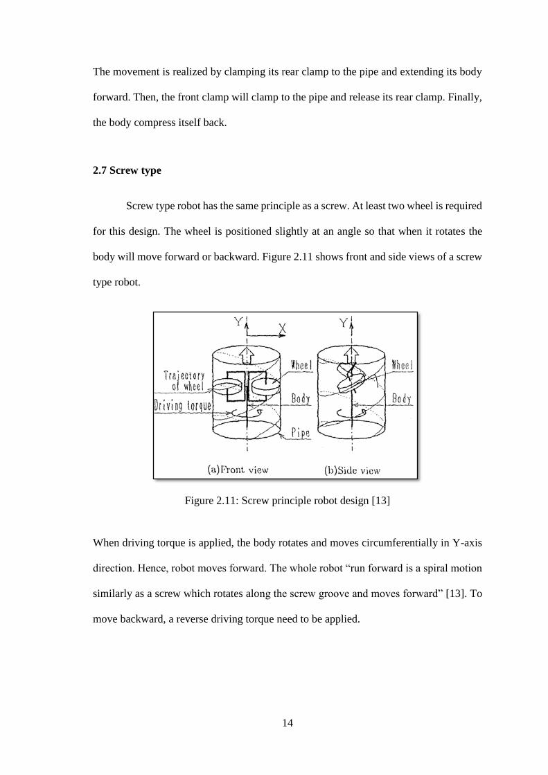
2.7 Screw type
Screw type robot has the same principle as a screw. At least two wheel is required
for this design. The wheel is positioned slightly at an angle so that when it rotates the
body will move forward or backward. Figure 2.11 shows front and side views of a screw
type robot.
Figure 2.11: Screw principle robot design [13]
When driving torque is applied, the body rotates and moves circumferentially in Y-axis
direction. Hence, robot moves forward. The whole robot “run forward is a spiral motion
similarly as a screw which rotates along the screw groove and moves forward” [13]. To
move backward, a reverse driving torque need to be applied.

15
2.8 Electro-magnetic force type [14]
Another type of micro robot designed based on electromagnetic actuator mounted
around its main body. Advantage of this design is the micro size of the robot starting as
low as 20 mm pipe diameter. The movement of this electromagnetic robot is controlled
by applying different voltage with different frequencies. Another advantage over other
design is the low power consumption of this design requiring around 1.2 watt while
travelling at a speed of 6-8 mm/s. Drawback of this design is the moving mechanism
which only able to move one direction.
2.9 Comparison of pipe inspection robots
Comparison of available pipe inspection robot types is tabulated in table 2.1.
Wheel and caterpillar type is the easiest to design with limitation from its electronic
components and actuators. But, it has the easiest steering mechanisms. Wall-press type
robot has its steering mechanism through the differential in speed of its driving module.
Inchworm, screw and electro-magnetic force type is the hardest to steer due to its
mechanical design which ease its forward movement.
Wall-press and walking type is best suited for pipe with varies diameter due to its
mechanical design which allow it to expand or shrink it sizes. The other designs have a
fixed size suitable for pipe with a more constant diameter throughout its length.
The actuators will determined the robot movement speeds. Wheel, caterpillar,
walking and screw will be a lot faster than the other types because the motors is
connected to either the wheels, tracks or its body. Inchworm will be very slow due to the
expanding and shrinking process of its body.

16
Table 2.1: Comparison between pipe inspection robots
Type Steering
ability
Robot size Advantage Disadvantage
Wheel Easy Fix size Very fast
movement
speed and can
carries high
payload
Possibility to
slips inside
pipe
Caterpillar Easy Fix size More grip than
wheel type
Possibility to
damage pipe
inner wall
Wall-press Medium Varies with
pipe diameter
Ability to
climb pipe
vertically
Low payload
due to small
actuators
Walking Easy Limited size Ability to
move almost
any surface
Requires
complex
controller and
most power
consumption
Inchworm Hard Micro size Micro size
enable it to a
Very slow
movement
speed
Screw Hard Fix size Highest
payload and
grips
Hard to move
in pipe
branches
Electro-
magnetic force
Hard Micro size Lowest power
consumption
Can only move
one direction
2.10 Components required
Understanding the requirements for each components needed is important before
developing a pipe inspection robot. Functions of all components can be seen in Table
2.2. A microcontroller board is required as the brain of the robot, its main control unit.
This microcontroller will need several input and output pins to communicate between the
user and other electronic components inside the robot. DC geared micro motor will be
used as its main driving module. This micro motor has to be small enough to fit in the
design but provides enough torque to drive the robot. Next, DC geared motor needed to
expand the robot size to fit variable sizes of pipe diameter. Besides that, motor driver is
an efficient method to control all the motor. Motor driver able to provide control to motor

17
direction and speed. Furthermore, servo motor will be used to control the pan and tilt
movement of the camera. This will ensure more area is covered by the camera. Last but
not least, a camera which will provide views for pipe inspections and a GUI to operate
the robot.
Table 2.2: Components function
Component
Function
Microcontroller board Main control unit
DC geared micro motor Main driving module
DC geared motor Expend robot to pipe diameter
Motor driver Control direction and speed
Servo motor Control camera movement
Camera Capture views inside pipe
Graphical User Interface Control robot operation and camera
display
2.11 Summary
Wall-press type will be the ideal shape for pipe inspection robot. By comparing
all types of robot previously used in pipe inspection robots, wall-press type provide more
flexibility for moving in multiple pipe dimensions. Since the driving module is located
circumferentially 120° apart it has high tractive force and this enables it to climb pipe
vertically. Steering mechanism of this type is inferior only to wheel and caterpillar type.
This robot will need at least two bodies each with its own set of driving module. Each
set will consist of three driving modules. Speed is not an important factor for this design
as inspection of pipe is a thorough process.
To develop a pipe inspection robot, several electronics and actuators are required.
A microcontroller board will act as the main control unit and handle all the interaction
between the actuators, electronics and operators. GUI will serve as the controller to
receive video feeds and control robot movements.
18
CHAPTER 3
METHODOLOGY
3.1 Introduction
In this chapter, method used to design and develop a pipe inspection robot is
described in details. This pipe inspection robot can be adjusted to fit into a pipe with
diameter of 200 mm. Besides that, it can climb vertical slope. This pipe inspection robot
has a steering mechanism by adjusting its driving module speed.
Section 3.2 in this chapter will also provide an overview of all the methods used
in this project. The methodology is also described using flowchart. While in section 3.3,
design specification of pipe inspection robot is described. Next, section 3.4 state the
selection of project requirements. Besides that, mechanical system development and
system programming are also covered in section 3.5 and section 3.6 respectively. After
that, section 3.7 will cover testing of robot with various surface conditions and vertical
slope climbing. Section 3.8 will evaluate the robot performance before the last section,
section 3.9 conclude this chapter.
3.2 Flow Chart
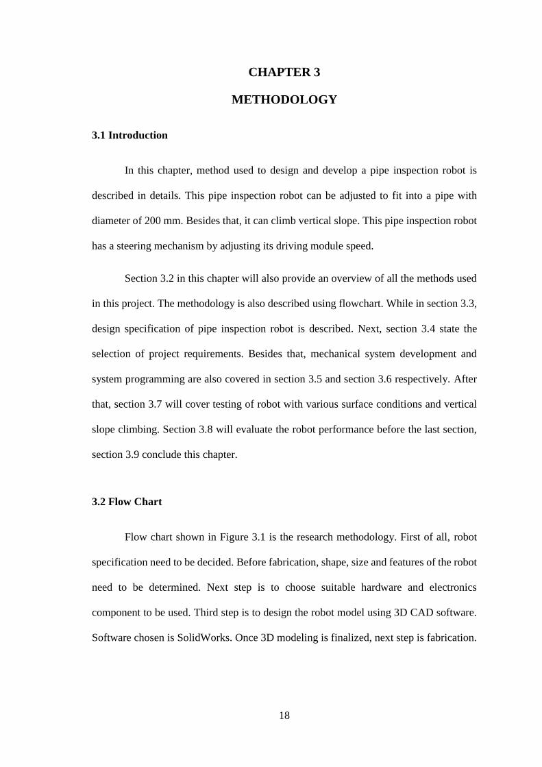
Flow chart shown in Figure 3.1 is the research methodology. First of all, robot
specification need to be decided. Before fabrication, shape, size and features of the robot
need to be determined. Next step is to choose suitable hardware and electronics
component to be used. Third step is to design the robot model using 3D CAD software.
Software chosen is SolidWorks. Once 3D modeling is finalized, next step is fabrication.
19
Figure 3.1: Research methodology flow chart
Fourth step will be programing of pipe inspection robot system. This pipe
inspection robot will have ten actuators. Actuators used are six DC geared micro motor,
two DC geared motor and two servo motor. To properly construct the system, all the
components are divided into four sections. Each section is tested separately to ease
troubleshooting process. Arduino Micro was used as the main microcontroller inside the
robot.
After all hardware and electronics components assembled, individual test is
carried out to ensure robot operate according to desired program.
20
Sixth step will be the testing of robot in multiple slope configuration. Finally, all
the recorded results will be analyzed to evaluate robot performance.
3.3 Design Specification
Before developing the prototype, it is important to determine all the parameter of
this pipe inspection robot. The most important parameters is the shape of the robot. Wall
press type is chosen as the basic shape for this pipe inspection robot. It is suitable for
various pipe diameter and provide the best traction while inside the pipe.
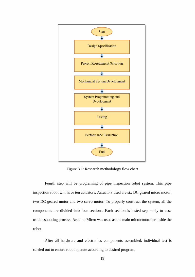
As shown in Table 3.1, the desired robot specification is done. This is to build a
sufficient size pipe inspection robot that can be easily fit all the hardware and electronics
required to operate this robot.
Table 3.1: Desired robot specifications
Pipe size 200 mm diameter
Input Voltage 12 Vdc
Weight Less than 2 kg
Total length 500 mm
Speed 0.1 m/s
Number of micro metal gear motor 6
Number of dc geared motor 2
Number of servo motor 2
Camera 1
Camera viewing angle 180° both vertical and horizontal
Based on Chapter Two, 6 driving module needed for this robot with each driving
module having its own motor. The position of each driving module is separated 120°
circumferentially. This is to ensure the stability of the robot and provide maximum
traction on all directions of the pipe.
21
Independent driving module is an important component to this design. In this
project, each driving module is equipped with its own motor. By having different speed
on its driving module, steering of the robot is achieved.
Some pipe inspection robot are able to turn more sharply due to mechanically
controlled joint. However, this was not considered in the design because it will
complicate the mechanical system and harder to implement in the programming. Instead,
it will be designed with a universal joint which will provide passive turning in horizontal
direction.
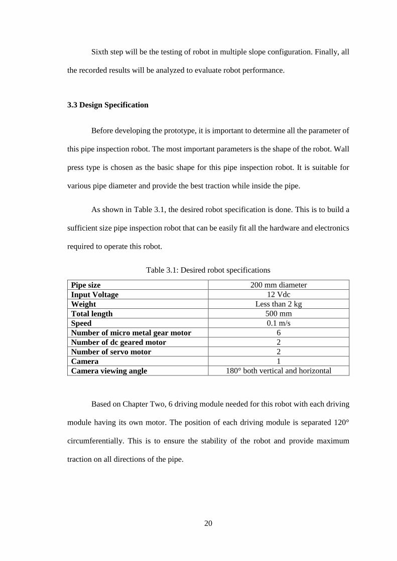
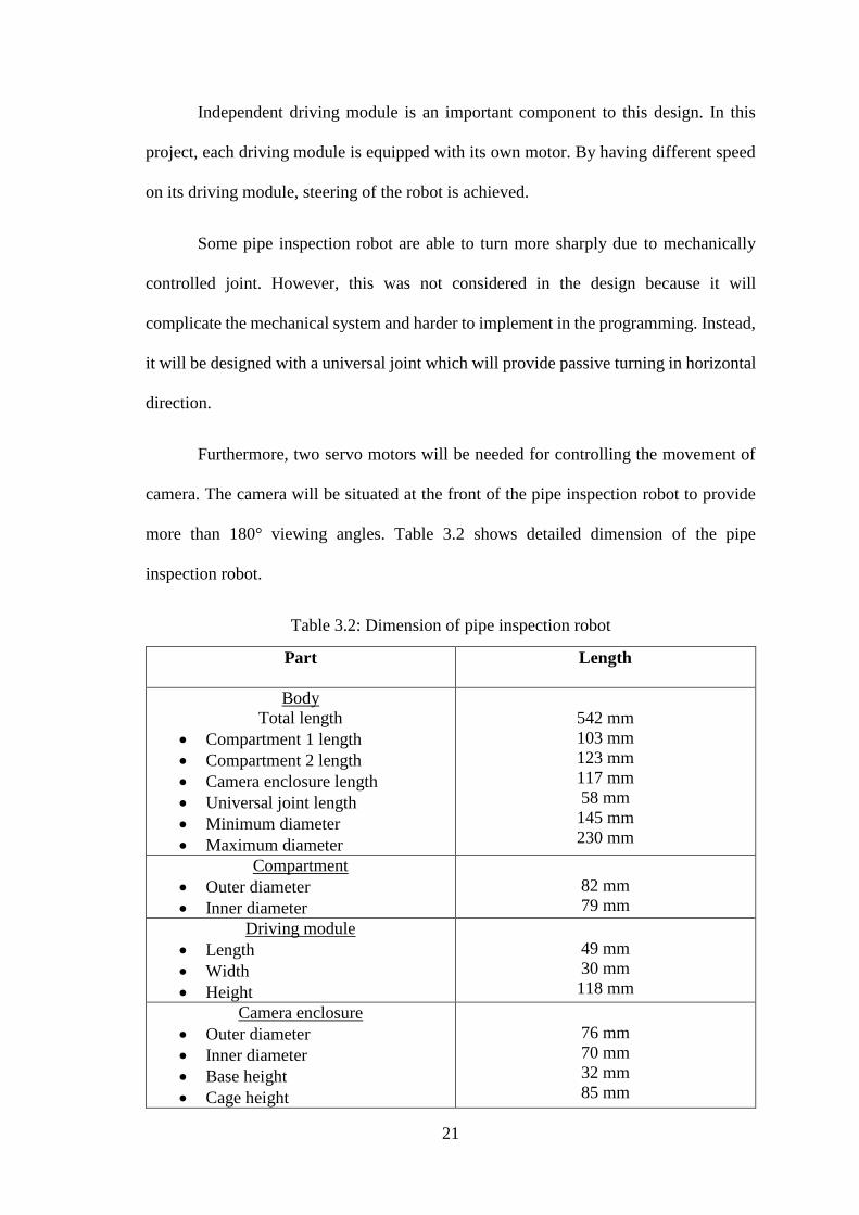
Furthermore, two servo motors will be needed for controlling the movement of
camera. The camera will be situated at the front of the pipe inspection robot to provide
more than 180° viewing angles. Table 3.2 shows detailed dimension of the pipe
inspection robot.
Table 3.2: Dimension of pipe inspection robot
Part
Length
Body
Total length
Compartment 1 length
Compartment 2 length
Camera enclosure length
Universal joint length
Minimum diameter
Maximum diameter
542 mm
103 mm
123 mm
117 mm
58 mm
145 mm
230 mm
Compartment
Outer diameter
Inner diameter
82 mm
79 mm
Driving module
Length
Width
Height
49 mm
30 mm
118 mm
Camera enclosure
Outer diameter
Inner diameter
Base height
Cage height
76 mm
70 mm
32 mm
85 mm
22
Table 3.2: Continued
Weight
Total
1.53 kg
3.4 Project Requirements Selections
Several types of actuators and microcontroller are needed to develop the pipe
inspection robot. This section states all the chosen components. Reasoning for
component selection are included within this section. They are listed below.
1. Arduino Micro ATmega32u4
2. Motor Driver
3. DC Micro Metal Geared Motor 45 rpm.
4. DC Geared Motor SPG30-60K
5. Micro Servo Motor MG90s
6. Camera JK-801
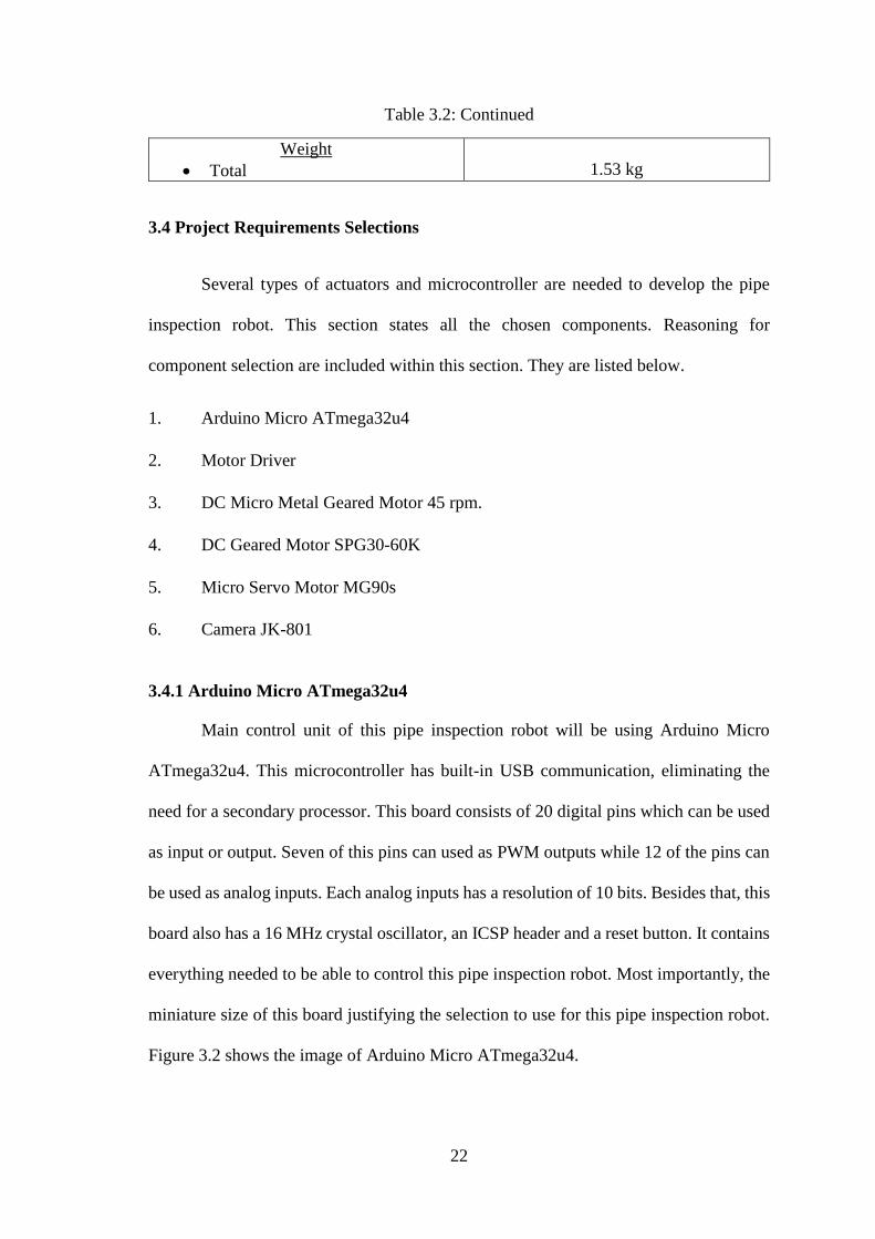
3.4.1 Arduino Micro ATmega32u4
Main control unit of this pipe inspection robot will be using Arduino Micro
ATmega32u4. This microcontroller has built-in USB communication, eliminating the
need for a secondary processor. This board consists of 20 digital pins which can be used
as input or output. Seven of this pins can used as PWM outputs while 12 of the pins can
be used as analog inputs. Each analog inputs has a resolution of 10 bits. Besides that, this
board also has a 16 MHz crystal oscillator, an ICSP header and a reset button. It contains
everything needed to be able to control this pipe inspection robot. Most importantly, the
miniature size of this board justifying the selection to use for this pipe inspection robot.
Figure 3.2 shows the image of Arduino Micro ATmega32u4.
23
Figure 3.2: Arduino Micro Atmega32u4 front view [15]
3.4.2 Motor Driver
Motor driver are the electronic circuits or IC to control the rotation direction and
the speed of the motors.
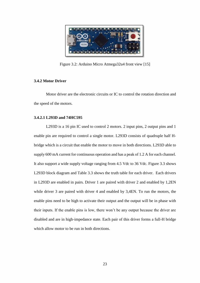
3.4.2.1 L293D and 74HC595
L293D is a 16 pin IC used to control 2 motors. 2 input pins, 2 output pins and 1
enable pin are required to control a single motor. L293D consists of quadruple half H-
bridge which is a circuit that enable the motor to move in both directions. L293D able to
supply 600 mA current for continuous operation and has a peak of 1.2 A for each channel.
It also support a wide supply voltage ranging from 4.5 Vdc to 36 Vdc. Figure 3.3 shows
L293D block diagram and Table 3.3 shows the truth table for each driver. Each drivers
in L293D are enabled in pairs. Driver 1 are paired with driver 2 and enabled by 1,2EN
while driver 3 are paired with driver 4 and enabled by 3,4EN. To run the motors, the
enable pins need to be high to activate their output and the output will be in phase with
their inputs. If the enable pins is low, there won’t be any output because the driver are
disabled and are in high-impedance state. Each pair of this driver forms a full-H bridge
which allow motor to be run in both directions.
24
Figure 3.3: L293D block diagram [16]
Table 3.3: Truth table for each driver
INPUTS
OUTPUT
Y
A EN
H H H
L H L
X L Z
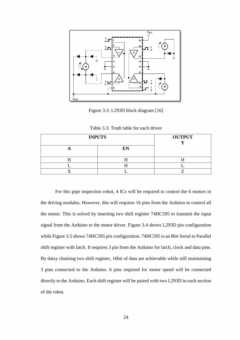
For this pipe inspection robot, 4 ICs will be required to control the 6 motors in
the driving modules. However, this will requires 16 pins from the Arduino to control all
the motor. This is solved by inserting two shift register 74HC595 to transmit the input
signal from the Arduino to the motor driver. Figure 3.4 shows L293D pin configuration
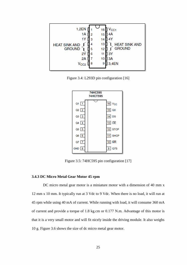
while Figure 3.5 shows 74HC595 pin configuration. 74HC595 is an 8bit Serial to Parallel
shift register with latch. It requires 3 pin from the Arduino for latch, clock and data pins.
By daisy chaining two shift register, 16bit of data are achievable while still maintaining
3 pins connected to the Arduino. 6 pins required for motor speed will be connected
directly to the Arduino. Each shift register will be paired with two L293D in each section
of the robot.
25
Figure 3.4: L293D pin configuration [16]
Figure 3.5: 74HC595 pin configuration [17]
3.4.3 DC Micro Metal Gear Motor 45 rpm
DC micro metal gear motor is a miniature motor with a dimension of 40 mm x
12 mm x 10 mm. It typically run at 3 Vdc to 9 Vdc. When there is no load, it will run at
45 rpm while using 40 mA of current. While running with load, it will consume 360 mA
of current and provide a torque of 1.8 kg.cm or 0.177 N.m. Advantage of this motor is
that it is a very small motor and will fit nicely inside the driving module. It also weighs
10 g. Figure 3.6 shows the size of dc micro metal gear motor.
26
Figure 3.6: DC micro metal gear motor [18]
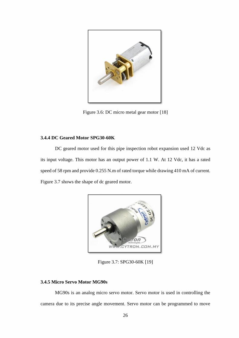
3.4.4 DC Geared Motor SPG30-60K
DC geared motor used for this pipe inspection robot expansion used 12 Vdc as
its input voltage. This motor has an output power of 1.1 W. At 12 Vdc, it has a rated
speed of 58 rpm and provide 0.255 N.m of rated torque while drawing 410 mA of current.
Figure 3.7 shows the shape of dc geared motor.
Figure 3.7: SPG30-60K [19]
3.4.5 Micro Servo Motor MG90s
MG90s is an analog micro servo motor. Servo motor is used in controlling the
camera due to its precise angle movement. Servo motor can be programmed to move

27
precisely in 1° increment or decrement. At 4.8 Vdc, this servo motor has a rated torque
of 1.8 kg.cm or 0.177 N.m and moves at a speed of 0.10 second for every 60°. Maximum
range for this servo is 180° and it has metal gear construction. Figure 3.8 shows servo
motor SG90.
Figure 3.8: Micro servo motor MG90s [20]
3.4.6 Camera JK-801
The camera used for this pipe inspection robot is a mini CMOS CCTV camera
JK-801. Image sensor used in this camera is a ¼” Color CMOS. It has a horizontal
resolution of 420 TVL providing 720 (H)*576 (V) in PAL and 720 (H)*480 (V) in NTSC
mode. This camera also has an auto white balancing thus easing the capture process in
dark area. Minimum illumination for this camera is 0.05 lux while consuming 9 Vdc of
voltage input and 70 mA of current. Figure 3.9 shows the shape of the camera.
Figure 3.9: Mini CMOS CCTV camera JK-801 [21]

28
3.5 Mechanical System Development
Mechanical system development for this robot will be divided into two phases.
The first phase will be 3D modeling using SolidWorks. All dimension and details of this
pipe inspection robot is drawn into the program. Once the dimension is satisfied and
finalized, it is then fabricated in fabrication phase.
3.5.1 3D Modeling Using SolidWorks
SolidWorks is a program used to draw the model of the pipe inspection robot.
Each parts of the robot is drawn into separate parts. All electronic components are also
included in the drawing to provide a clearer visual representation of the actual pipe
inspection robot. Figure 3.10 shows the schematic drawing for the total length of the
robot while Figure 3.11 shows the maximum diameter of the robot.
Figure 3.10: Schematic drawing of the total length of the robot
29
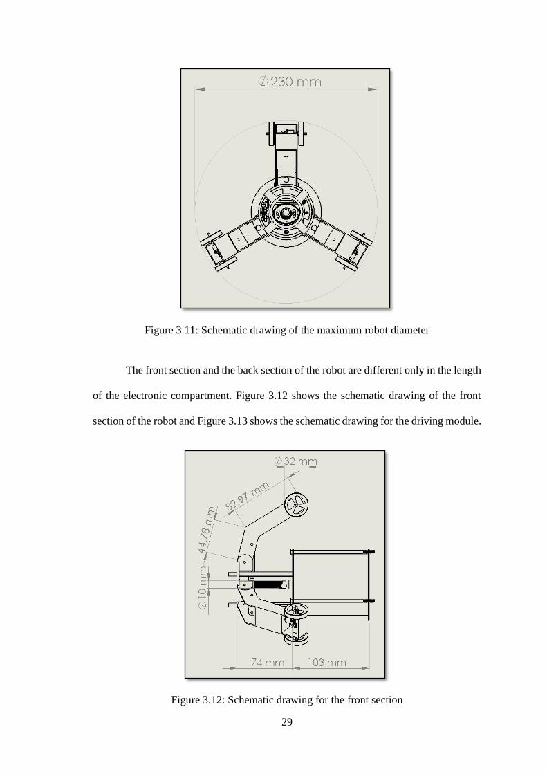
Figure 3.11: Schematic drawing of the maximum robot diameter
The front section and the back section of the robot are different only in the length
of the electronic compartment. Figure 3.12 shows the schematic drawing of the front
section of the robot and Figure 3.13 shows the schematic drawing for the driving module.
Figure 3.12: Schematic drawing for the front section
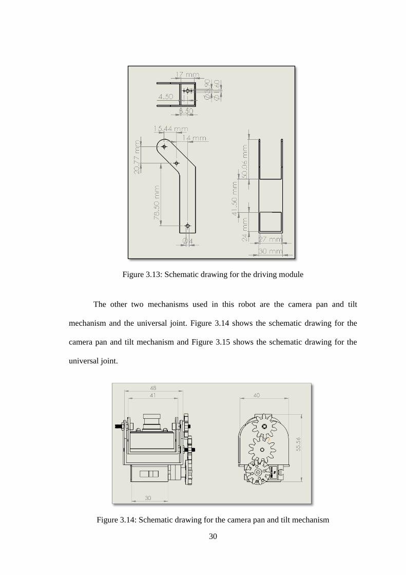
30
Figure 3.13: Schematic drawing for the driving module
The other two mechanisms used in this robot are the camera pan and tilt
mechanism and the universal joint. Figure 3.14 shows the schematic drawing for the
camera pan and tilt mechanism and Figure 3.15 shows the schematic drawing for the
universal joint.
Figure 3.14: Schematic drawing for the camera pan and tilt mechanism
31
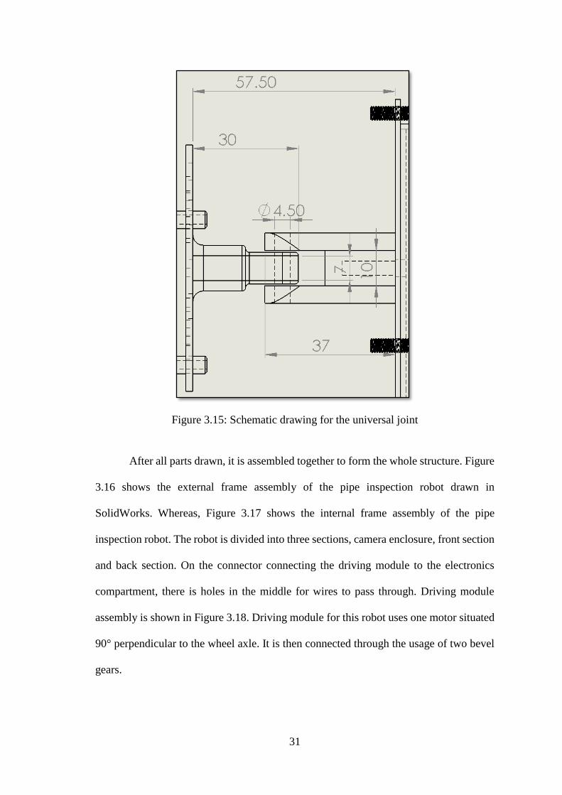
Figure 3.15: Schematic drawing for the universal joint
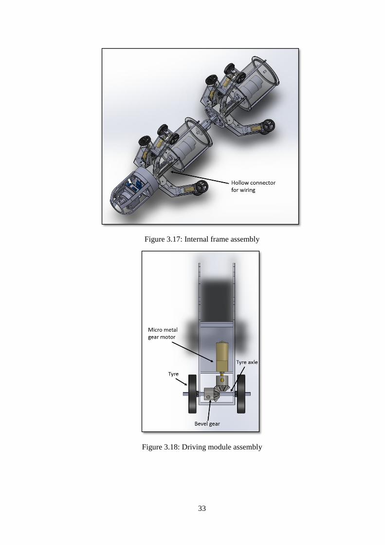
After all parts drawn, it is assembled together to form the whole structure. Figure
3.16 shows the external frame assembly of the pipe inspection robot drawn in
SolidWorks. Whereas, Figure 3.17 shows the internal frame assembly of the pipe
inspection robot. The robot is divided into three sections, camera enclosure, front section
and back section. On the connector connecting the driving module to the electronics
compartment, there is holes in the middle for wires to pass through. Driving module
assembly is shown in Figure 3.18. Driving module for this robot uses one motor situated
90° perpendicular to the wheel axle. It is then connected through the usage of two bevel
gears.

32
3.5.2 Fabrication
Fabrication of this robot is done using a 3D printer which is for rapid prototyping
purposes. The purpose of using a 3D printer is to save cost to build this pipe inspection
robot prototype. Once all the files are finalized, it is then converted into STL files for use
by the 3D printer. The 3D printer uses PLA as its printing filament. PLA is a bio-
degradable polymer produced form lactic acid. It is also harder than ABS and melts at
around 180°C to 220° C. Printing is done parts by parts considering some parts are large
and require very long time to print. All parts are printed before and programming is done.
Figure 3.16: External frame assembly
33
Figure 3.17: Internal frame assembly
Figure 3.18: Driving module assembly
34
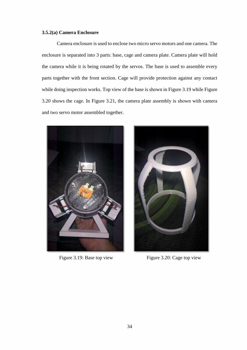
3.5.2(a) Camera Enclosure
Camera enclosure is used to enclose two micro servo motors and one camera. The
enclosure is separated into 3 parts: base, cage and camera plate. Camera plate will hold
the camera while it is being rotated by the servos. The base is used to assemble every
parts together with the front section. Cage will provide protection against any contact
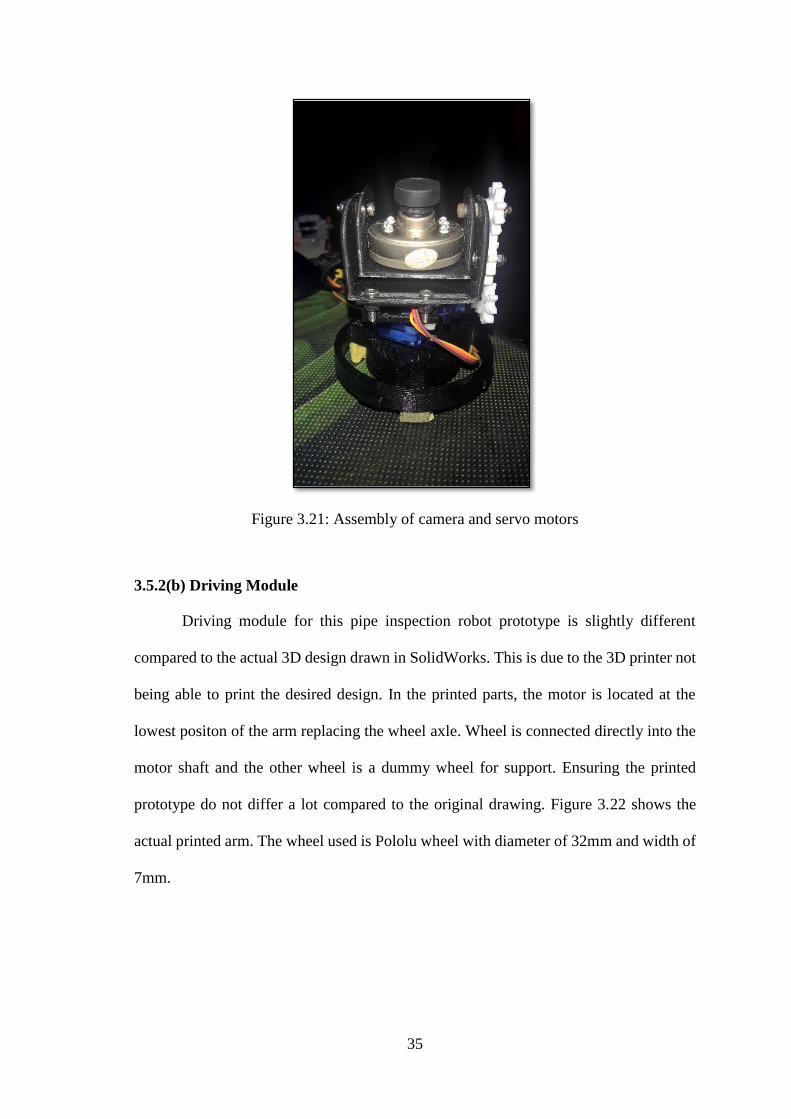
while doing inspection works. Top view of the base is shown in Figure 3.19 while Figure
3.20 shows the cage. In Figure 3.21, the camera plate assembly is shown with camera
and two servo motor assembled together.
Figure 3.19: Base top view
Figure 3.20: Cage top view
35
Figure 3.21: Assembly of camera and servo motors
3.5.2(b) Driving Module
Driving module for this pipe inspection robot prototype is slightly different
compared to the actual 3D design drawn in SolidWorks. This is due to the 3D printer not
being able to print the desired design. In the printed parts, the motor is located at the
lowest positon of the arm replacing the wheel axle. Wheel is connected directly into the
motor shaft and the other wheel is a dummy wheel for support. Ensuring the printed
prototype do not differ a lot compared to the original drawing. Figure 3.22 shows the
actual printed arm. The wheel used is Pololu wheel with diameter of 32mm and width of
7mm.

36
Figure 3.22: Driving module arm
3.5.2(c) Electronic Compartment
Compartment to store all the electronics and wiring is made up of a simple
cylindrical shape. One dc geared motor is assembled inside the compartment for
expansion and contraction of the driving module arms. This allow the robot to pass
through any obstruction inside the pipe. Installation of the dc motor inside the
compartment is shown in Figure 3.23 and Figure 3.24 shows the threaded rod used for
expansion and contraction.

37
Figure 3.23: DC motor inside electronic compartment
Figure 3.24: Threaded rod for expansion and contraction
38
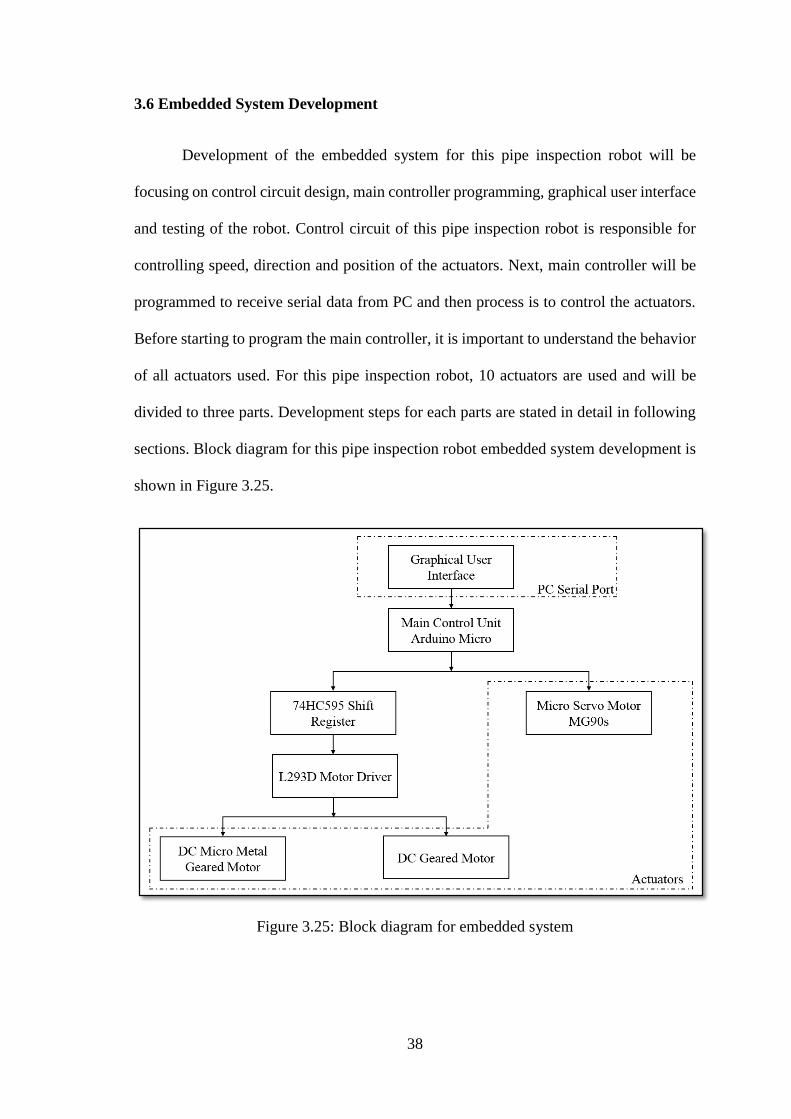
3.6 Embedded System Development
Development of the embedded system for this pipe inspection robot will be
focusing on control circuit design, main controller programming, graphical user interface
and testing of the robot. Control circuit of this pipe inspection robot is responsible for
controlling speed, direction and position of the actuators. Next, main controller will be
programmed to receive serial data from PC and then process is to control the actuators.
Before starting to program the main controller, it is important to understand the behavior
of all actuators used. For this pipe inspection robot, 10 actuators are used and will be
divided to three parts. Development steps for each parts are stated in detail in following
sections. Block diagram for this pipe inspection robot embedded system development is
shown in Figure 3.25.
Figure 3.25: Block diagram for embedded system
39
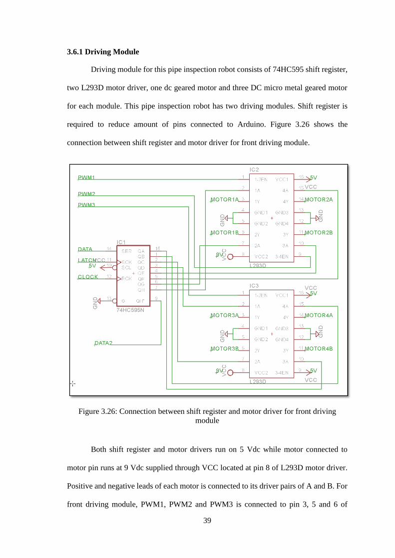
3.6.1 Driving Module
Driving module for this pipe inspection robot consists of 74HC595 shift register,
two L293D motor driver, one dc geared motor and three DC micro metal geared motor
for each module. This pipe inspection robot has two driving modules. Shift register is
required to reduce amount of pins connected to Arduino. Figure 3.26 shows the
connection between shift register and motor driver for front driving module.
Figure 3.26: Connection between shift register and motor driver for front driving
module
Both shift register and motor drivers run on 5 Vdc while motor connected to
motor pin runs at 9 Vdc supplied through VCC located at pin 8 of L293D motor driver.
Positive and negative leads of each motor is connected to its driver pairs of A and B. For
front driving module, PWM1, PWM2 and PWM3 is connected to pin 3, 5 and 6 of
40
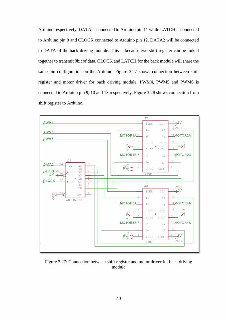
Arduino respectively. DATA is connected to Arduino pin 11 while LATCH is connected
to Arduino pin 8 and CLOCK connected to Arduino pin 12. DATA2 will be connected
to DATA of the back driving module. This is because two shift register can be linked
together to transmit 8bit of data. CLOCK and LATCH for the back module will share the
same pin configuration on the Arduino. Figure 3.27 shows connection between shift
register and motor driver for back driving module. PWM4, PWM5 and PWM6 is
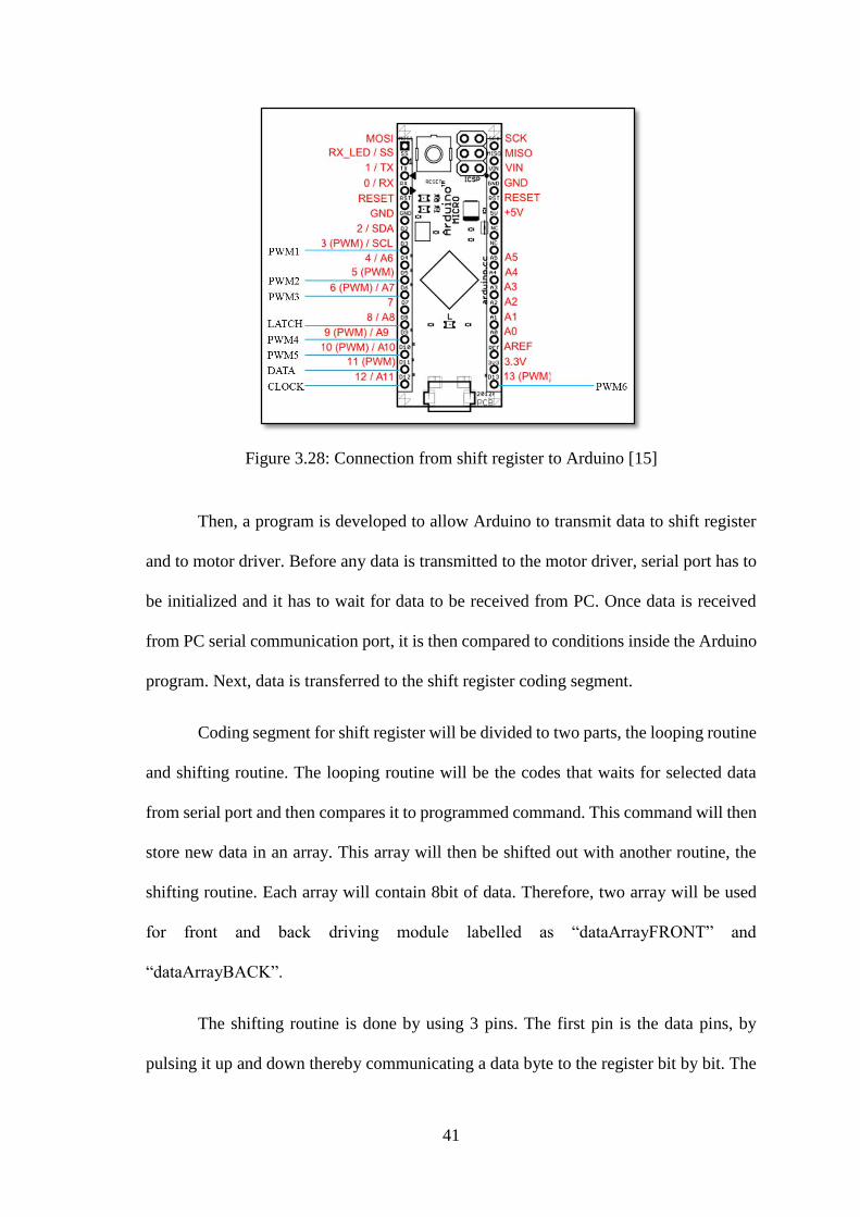
connected to Arduino pin 9, 10 and 13 respectively. Figure 3.28 shows connection from
shift register to Arduino.
Figure 3.27: Connection between shift register and motor driver for back driving
module
41
Figure 3.28: Connection from shift register to Arduino [15]
Then, a program is developed to allow Arduino to transmit data to shift register
and to motor driver. Before any data is transmitted to the motor driver, serial port has to
be initialized and it has to wait for data to be received from PC. Once data is received
from PC serial communication port, it is then compared to conditions inside the Arduino
program. Next, data is transferred to the shift register coding segment.
Coding segment for shift register will be divided to two parts, the looping routine
and shifting routine. The looping routine will be the codes that waits for selected data
from serial port and then compares it to programmed command. This command will then
store new data in an array. This array will then be shifted out with another routine, the
shifting routine. Each array will contain 8bit of data. Therefore, two array will be used
for front and back driving module labelled as “dataArrayFRONT” and
“dataArrayBACK”.
The shifting routine is done by using 3 pins. The first pin is the data pins, by
pulsing it up and down thereby communicating a data byte to the register bit by bit. The

42
second pin is the clock pin used to indicate exact position between bits. And the last pin,
latch pin is used transmit the whole byte. By having all output pins on the shift register
to output in parallel is known as the “parallel output” part. Since there is two data array,
the first data array to be transmitted is “dataArrayBACK” and then “dataArrayFRONT”.
This is because, shift register serially shift out the data from the MSB to the LSB and the
front driving module having the LSB while back driving module having the MSB.
Figure 3.29 shows the flow chart of programming code for receiving serial data
from PC and transmitting it to motor driver. For micro metal geared motor, pulse width
modulation is supplied to its corresponding enable pins to allow speed adjustment while
5Vdc is connected to enable pins for dc geared motor which is used for robot expansion
and contraction to increase or reduce its diameter.
Figure 3.29: Flow chart of programming code for receiving serial data from PC and
transmitting it to motor driver
43
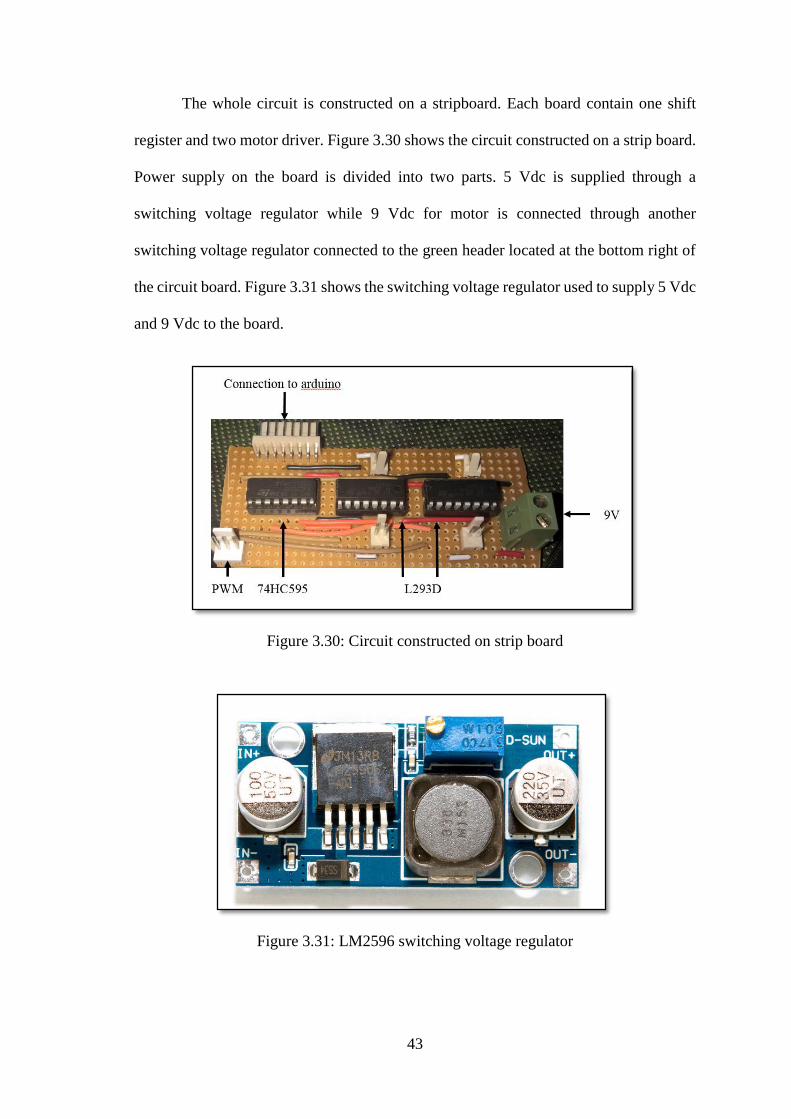
The whole circuit is constructed on a stripboard. Each board contain one shift
register and two motor driver. Figure 3.30 shows the circuit constructed on a strip board.
Power supply on the board is divided into two parts. 5 Vdc is supplied through a
switching voltage regulator while 9 Vdc for motor is connected through another
switching voltage regulator connected to the green header located at the bottom right of
the circuit board. Figure 3.31 shows the switching voltage regulator used to supply 5 Vdc
and 9 Vdc to the board.
Figure 3.30: Circuit constructed on strip board
Figure 3.31: LM2596 switching voltage regulator
44
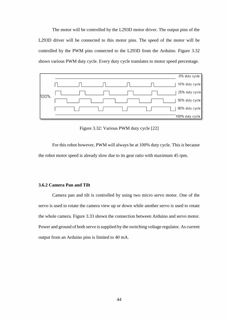
The motor will be controlled by the L293D motor driver. The output pins of the
L293D driver will be connected to this motor pins. The speed of the motor will be
controlled by the PWM pins connected to the L293D from the Arduino. Figure 3.32
shows various PWM duty cycle. Every duty cycle translates to motor speed percentage.
Figure 3.32: Various PWM duty cycle [22]
For this robot however, PWM will always be at 100% duty cycle. This is because
the robot motor speed is already slow due to its gear ratio with maximum 45 rpm.
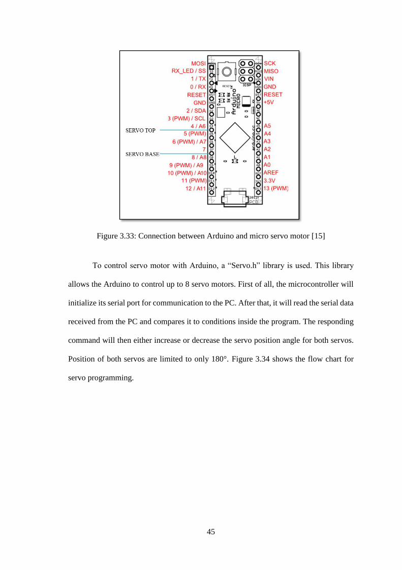
3.6.2 Camera Pan and Tilt
Camera pan and tilt is controlled by using two micro servo motor. One of the
servo is used to rotate the camera view up or down while another servo is used to rotate
the whole camera. Figure 3.33 shown the connection between Arduino and servo motor.
Power and ground of both servo is supplied by the switching voltage regulator. As current
output from an Arduino pins is limited to 40 mA.
45
Figure 3.33: Connection between Arduino and micro servo motor [15]
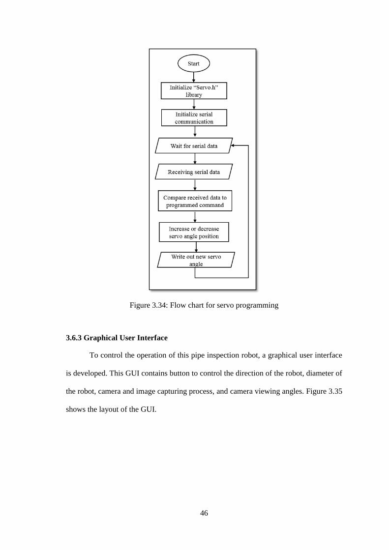
To control servo motor with Arduino, a “Servo.h” library is used. This library
allows the Arduino to control up to 8 servo motors. First of all, the microcontroller will
initialize its serial port for communication to the PC. After that, it will read the serial data
received from the PC and compares it to conditions inside the program. The responding
command will then either increase or decrease the servo position angle for both servos.
Position of both servos are limited to only 180°. Figure 3.34 shows the flow chart for
servo programming.
46
Figure 3.34: Flow chart for servo programming
3.6.3 Graphical User Interface
To control the operation of this pipe inspection robot, a graphical user interface
is developed. This GUI contains button to control the direction of the robot, diameter of
the robot, camera and image capturing process, and camera viewing angles. Figure 3.35
shows the layout of the GUI.

47
Figure 3.35: Layout of the graphical user interface
After opening the application, users will be allowed to search for communication
port and camera. Once the GUI connected to the robot’s communication port, then only
the robot control button, diameter button and camera control button will be enabled. The
capture button and record button will only be enabled once a camera is connected. User
will still be allowed to connect to the camera even though the application is not connected
to the robot’s serial communication port. However, only capture and record button will
be enabled and camera control button will still be disabled. Figure 3.36 show the flow
chart for this graphical user interface.

48
Figure 3.36: Flow chart for graphical user interface
For serial port communication, when no button is pressed, a serial data of “0,” is
sent to the Arduino through the serial port. This data will be interpreted by the Arduino
as “STOP”. Motors will not be moving in this condition. Others serial data transmitted
will provide different interpretation to the Arduino. In total, 16 conditions will be
checked by the Arduino. However, this GUI will only transmit 1 serial data at a time.
Serial data transmitted by this GUI ranging from 0 to 15 is followed by a comma. This
comma is to indicate the end point of the data being transmitted.
When a camera is connected, pressing the capture button will capture the current
frame inside the video frame. The captured image will then be stored in a folder named
“Images” located in the application directories. This directory will open once image is
saved. For video recording, the application will collect the current frame and place it in
49
a recoding function. The application will collect 25 frames per second and combine it to
become a video. Once the record button is turn off, the record function is turn off and the
videos can be viewed from its saved directories named “Videos”.
3.7 Testing
Test are carried out after mechanical system are fabricated and system
programming and development of the robot is programmed and constructed. Major
consideration of the pipe inspection robot development are drivability, steering ability
and camera viewing vision.
3.7.1 Drivability Test
Drivability test is carried out to test both mechanical design and electronics.
Mechanical design are a major consideration for this robot. Without the proper
mechanical ability, all other parts will fail even though other parts are performing as
expected.
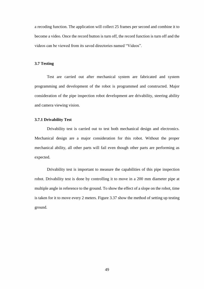
Drivability test is important to measure the capabilities of this pipe inspection
robot. Drivability test is done by controlling it to move in a 200 mm diameter pipe at
multiple angle in reference to the ground. To show the effect of a slope on the robot, time
is taken for it to move every 2 meters. Figure 3.37 show the method of setting up testing
ground.
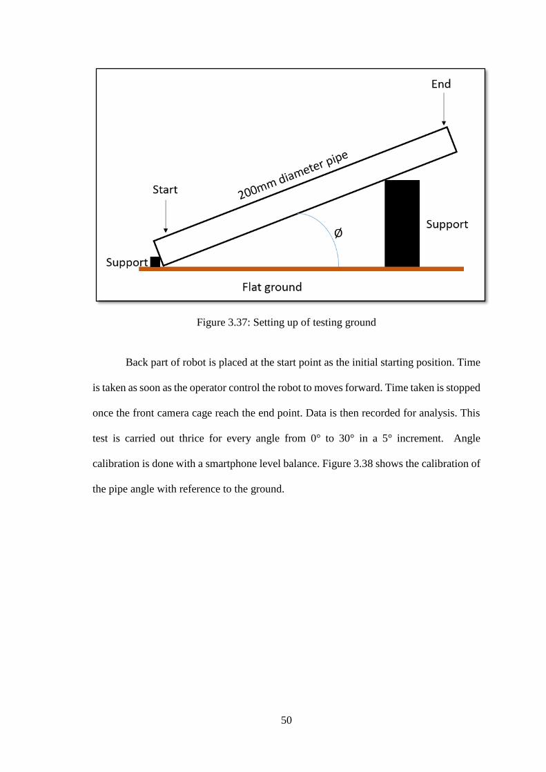
50
Figure 3.37: Setting up of testing ground
Back part of robot is placed at the start point as the initial starting position. Time
is taken as soon as the operator control the robot to moves forward. Time taken is stopped
once the front camera cage reach the end point. Data is then recorded for analysis. This
test is carried out thrice for every angle from 0° to 30° in a 5° increment. Angle
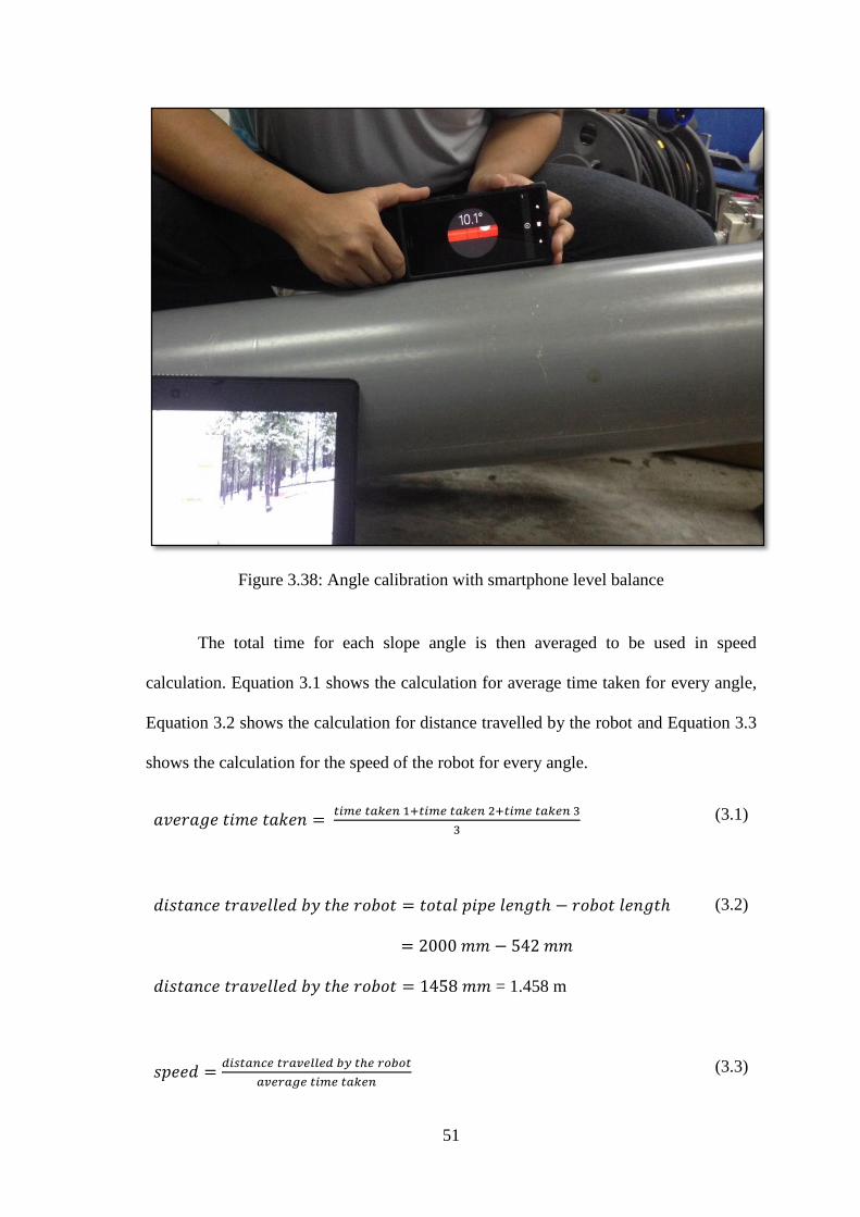
calibration is done with a smartphone level balance. Figure 3.38 shows the calibration of
the pipe angle with reference to the ground.
51
Figure 3.38: Angle calibration with smartphone level balance
The total time for each slope angle is then averaged to be used in speed
calculation. Equation 3.1 shows the calculation for average time taken for every angle,
Equation 3.2 shows the calculation for distance travelled by the robot and Equation 3.3
shows the calculation for the speed of the robot for every angle.
𝑎𝑣𝑒𝑟𝑎𝑔𝑒 𝑡𝑖𝑚𝑒 𝑡𝑎𝑘𝑒𝑛 = 𝑡𝑖𝑚𝑒 𝑡𝑎𝑘𝑒𝑛 1+𝑡𝑖𝑚𝑒 𝑡𝑎𝑘𝑒𝑛 2+𝑡𝑖𝑚𝑒 𝑡𝑎𝑘𝑒𝑛 3
3
(3.1)
𝑑𝑖𝑠𝑡𝑎𝑛𝑐𝑒 𝑡𝑟𝑎𝑣𝑒𝑙𝑙𝑒𝑑 𝑏𝑦 𝑡ℎ𝑒 𝑟𝑜𝑏𝑜𝑡 = 𝑡𝑜𝑡𝑎𝑙 𝑝𝑖𝑝𝑒 𝑙𝑒𝑛𝑔𝑡ℎ − 𝑟𝑜𝑏𝑜𝑡 𝑙𝑒𝑛𝑔𝑡ℎ
= 2000 𝑚𝑚 − 542 𝑚𝑚
𝑑𝑖𝑠𝑡𝑎𝑛𝑐𝑒 𝑡𝑟𝑎𝑣𝑒𝑙𝑙𝑒𝑑 𝑏𝑦 𝑡ℎ𝑒 𝑟𝑜𝑏𝑜𝑡 = 1458 𝑚𝑚 = 1.458 m
(3.2)
𝑠𝑝𝑒𝑒𝑑 =𝑑𝑖𝑠𝑡𝑎𝑛𝑐𝑒 𝑡𝑟𝑎𝑣𝑒𝑙𝑙𝑒𝑑 𝑏𝑦 𝑡ℎ𝑒 𝑟𝑜𝑏𝑜𝑡
𝑎𝑣𝑒𝑟𝑎𝑔𝑒 𝑡𝑖𝑚𝑒 𝑡𝑎𝑘𝑒𝑛 (3.3)
52
The distance travelled by the robot that is 1.458 m will be used to calculate the
speed of the robot after the average time has been taken.
3.7.2 Camera viewing Vision
Camera is a very important components in this pipe inspection robot. Without it,
monitoring of internal pipe conditions will be almost impossible to do. Thus, it is
important to test the effectiveness of the camera used in this pipe inspection robot. This
is done by capturing pictures and recording videos while testing is ongoing. The resulting
pictures and videos must then be improved upon next testing. Improvement is done until
the required robot vision is obtained.
3.8 Performance Evaluation
In previous section, real time performance of the pipe inspection robot has been
discussed. Problems faced during testing and its solution has also been discussed. Videos
and photos taken during testing is used to benchmark the performance of the pipe
inspection robot.
3.9 Summary
In this chapter, the methodology is divided into two separate categories. The first
categories is designing and construction of the mechanical mechanism of the pipe
inspection robot. The other categories is designing, construction and programming of the
embedded system development. Testing is the most difficult part for this chapter since
many problem occurring during the duration of the test. However, improvement is
necessary to solve the problems. Speed and direction of the robot is altered using pulse
width modulation method to maintain a straight line motion for the robot.

53
CHAPTER 4
RESULTS AND DISCUSSIONS
4.1 Introduction
Problem encountered in the previous chapter and results of testing will be
discussed in this chapter. In this chapter, there will be 4 section. The first section, section
4.2 discusses on the result of mechanical system development and section 4.3 discusses
on the results for embedded system development. After that, section 4.4 discusses on
results obtained during testing and finally section 4.5 discusses the real time performance
evaluation of the pipe inspection robot.
4.2 Result of Mechanical System Development
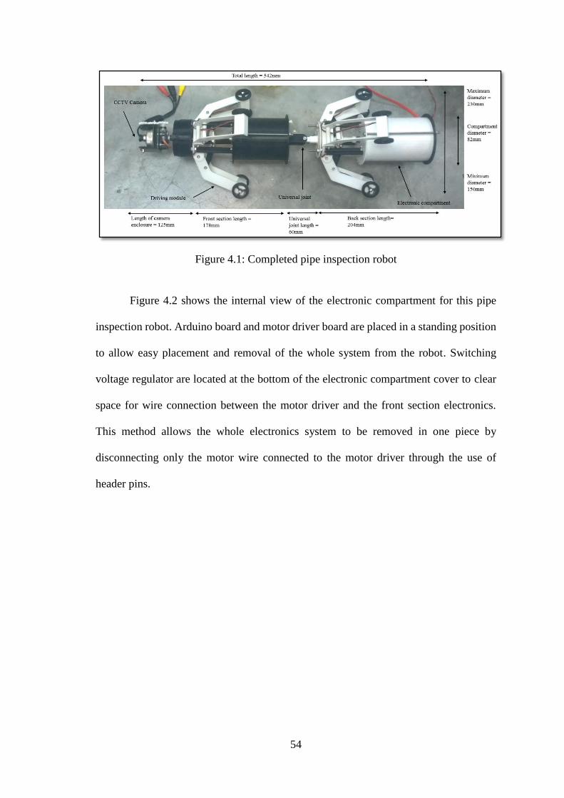
Complete pipe inspection robot is shown in Figure 4.1. There are three main
sections of the robots. The front camera section, front driving module section and the
back driving module section. Universal joint located between front and back driving
module section allow the robot to turn 90 degree to the left or right in a horizontal
movements. The performance of the driving module will be discussed in next section.
All moving parts are screwed using bolt and nyloc nuts to prevent the nut from
unscrewing itself while robot is still operating. Each driving module have 2 wheels
totaling to 6 wheels for each front and back section. Motor is securely placed inside the
driving module to ensure no loss parts. Front and back electronic compartment is made
up of different color to differentiate the differences in length.
54
Figure 4.1: Completed pipe inspection robot
Figure 4.2 shows the internal view of the electronic compartment for this pipe
inspection robot. Arduino board and motor driver board are placed in a standing position
to allow easy placement and removal of the whole system from the robot. Switching
voltage regulator are located at the bottom of the electronic compartment cover to clear
space for wire connection between the motor driver and the front section electronics.
This method allows the whole electronics system to be removed in one piece by
disconnecting only the motor wire connected to the motor driver through the use of
header pins.
55
Figure 4.2: (a) Top view (b) Side view (c) Process of inserting the electronics into the
electronic compartment
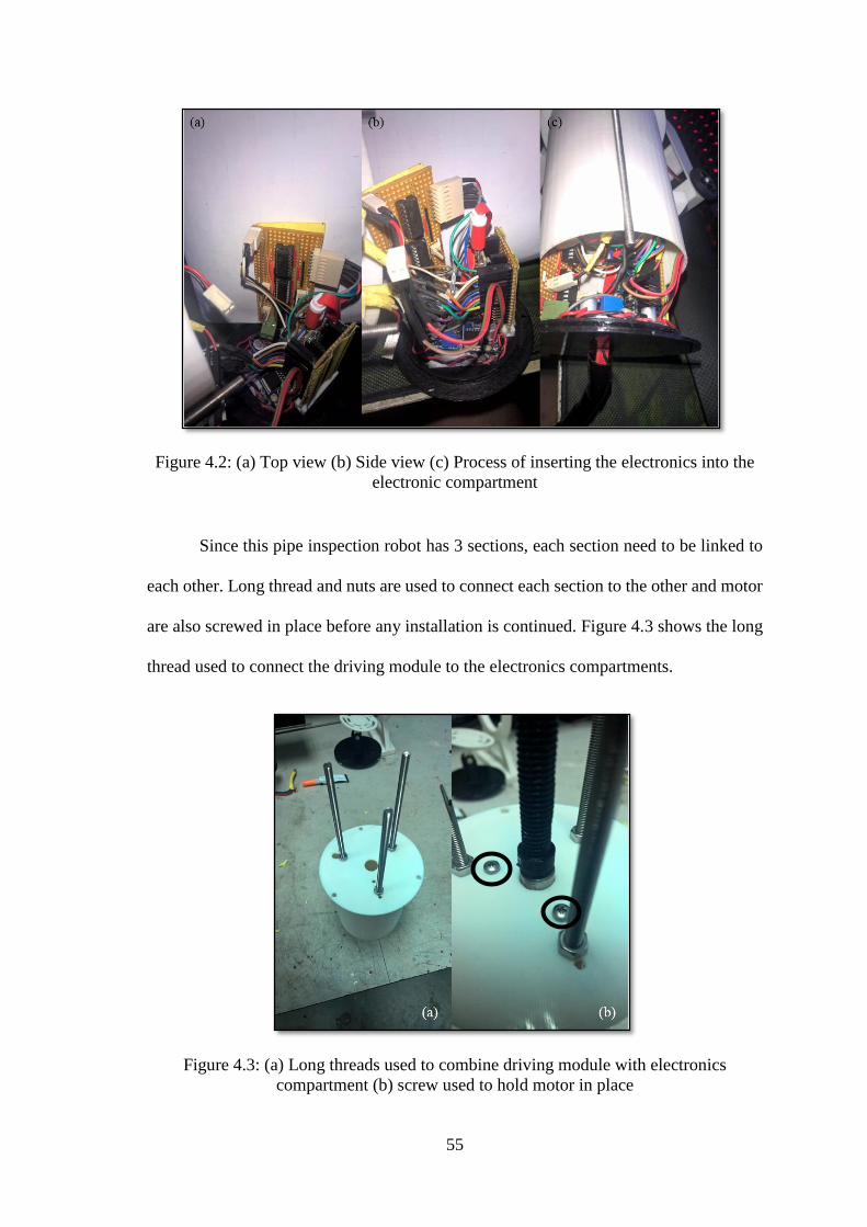
Since this pipe inspection robot has 3 sections, each section need to be linked to
each other. Long thread and nuts are used to connect each section to the other and motor
are also screwed in place before any installation is continued. Figure 4.3 shows the long
thread used to connect the driving module to the electronics compartments.
Figure 4.3: (a) Long threads used to combine driving module with electronics
compartment (b) screw used to hold motor in place

56
Because the wires are connected from the camera section to the back driving
module section, it needs to be inside the electronic compartment as much as possible to
avoid from any possible obstacles that might damages the wires. Figure 4.4 shows the
wiring of the robot.
Figure 4.4: (a) Wiring from front to back section (b) Motor wiring passing through a
tube (c) Power and signal wire wrapped with cable wrapper
4.3 Result of Embedded System Development
There are three parts to this pipe inspection robot embedded system development.
The first part are the driving module while second part are the camera pan and tilt
function. Finally, graphical user interfaces made up the last part of this embedded system
development. This section will discuss the results for embedded system development for
this pipe inspection robot.
57
4.3.1 Driving Module
Based on Figure 3.24 in chapter 3, the circuit is used to control 4 motors. Three
of the motor is a DC micro metal gear motor and the other motor is a DC geared motor.
Operation of this circuit is controlled by three PWM pins from Arduino and three signal
pins from the Arduino. The signal pins consists of DATA, LATCH and CLOCK pins.
The board is power with 5 Vdc supplied by a switching voltage regulator. This is to
ensure that no current limitation will occur when operating 4 DC motors. Another
switching regulator is used to supply 9 Vdc to the L293D motor driver for motor power
supply. In this configuration, the 5 Vdc supplied for logic operation won’t be interrupted
by the motor power consumption.
Each driving module has its own DC micro metal gear motor to ensure that every
driving module that is in contact with the inner wall of the pipe will provide the robot
with grip and torque required for it to moves. Reliability of these motor will be discussed
in testing of the motor speed section.
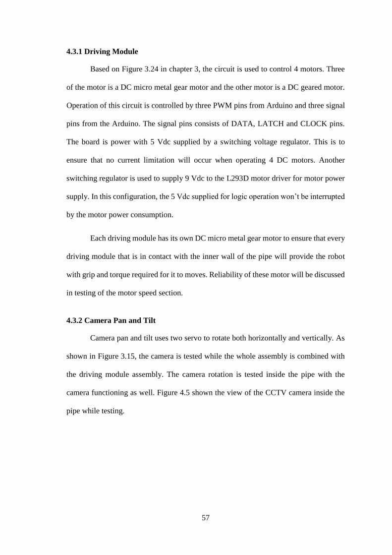
4.3.2 Camera Pan and Tilt
Camera pan and tilt uses two servo to rotate both horizontally and vertically. As
shown in Figure 3.15, the camera is tested while the whole assembly is combined with
the driving module assembly. The camera rotation is tested inside the pipe with the
camera functioning as well. Figure 4.5 shown the view of the CCTV camera inside the
pipe while testing.
58
Figure 4.5: (a) Camera view rotated 90° to the left (b) Camera view at 0° (c) Camera
view rotated 90° to the right
As seen in figure above, the images shows that the servo are unable to rotate the
camera exactly 90° to the left. This is due to several factors. The first factors is the
fabrication limitations. Although the design is expected to be able to achieve the desired
angle, 3d printer used to print the actual camera assembly are not able to print as
accurately as the required dimension. This cause some of the camera assembly to be loose
and decrease the rotation accuracy. Second factor is the servo used for this camera
assembly. Since micro servo is used, it is unable to provide enough torque to rotate the
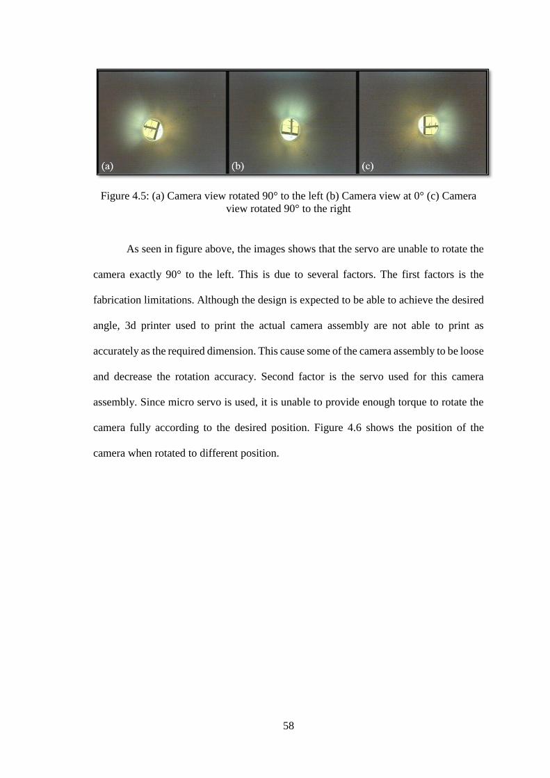
camera fully according to the desired position. Figure 4.6 shows the position of the
camera when rotated to different position.
59
Figure 4.6: (a) Camera rotated 90° upwards (b) Camera at horizontal position (c)
Camera at rotated 90° downwards
However, we can say that the reliability of the camera is desirable. Good quality
images are able to be taken from the camera and the video recoded by this camera are
also good enough for monitoring purposes. This is also because, LED are used to increase
the ambience light inside the pipe.
4.3.3 Graphical User Interface
The application for this pipe inspection robot has been successfully developed.
The GUI are able to connect and control the robot. The GUI provide the user with the
robot movement control and dimension. This application is also able to capture images
directly from the camera inside the robot. Videos are also able to be recorded for later
reviewing purposes. This application will ensure that the operation of the robot is kept
minimized for smooth operation.

60
4.4 Testing Results
Testing result will be discussing on the results of the drivability and the robot
vision.
4.4.1 Drivability Result
The speed for this pipe inspection robot is shown is Table 4.1. Testing is done
from 0 degree to 30 degrees only because for an angle more than 30 degrees, the robot
will not be able to climb. The motor used do not provide enough torque to drive the robot.
However, the motor does provide enough torque to hold the robot in place at an angle
more than 30 degrees.
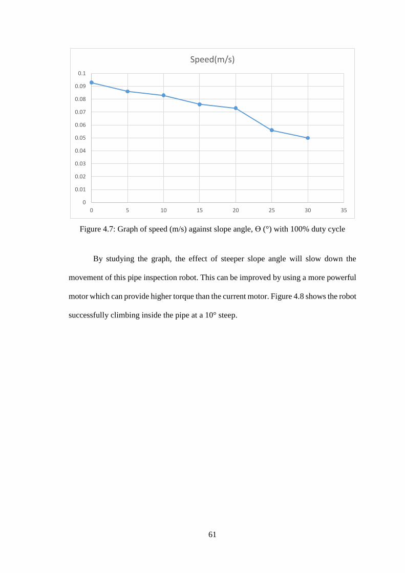
Table 4.1: Speed of pipe inspection robot for various slope angle
Slope angle
Ɵ(°)
Time taken(s)
Average
time
taken(s)
Speed(m/s)
1
2
3
0 15.855 15.828 15.581 15.755 0.093
5 16.417 17.862 16.595 16.958 0.086
10 17.715 17.606 17.386 17.569 0.083
15 19.030 19.421 19.392 19.281 0.076
20 20.389 19.928 19.817 20.045 0.073
25 26.218 26.570 25.297 26.028 0.056
30 28.344 29.775 29.297 29.139 0.050
Data obtained are then plotted for speed against slope angle to show the effect of
higher slope towards the robot speed. Figure 4.7 shows a graph of speed against slope
angle.
61
Figure 4.7: Graph of speed (m/s) against slope angle, Ɵ (°) with 100% duty cycle
By studying the graph, the effect of steeper slope angle will slow down the
movement of this pipe inspection robot. This can be improved by using a more powerful
motor which can provide higher torque than the current motor. Figure 4.8 shows the robot
successfully climbing inside the pipe at a 10° steep.
0
0.01
0.02
0.03
0.04
0.05
0.06
0.07
0.08
0.09
0.1
0 5 10 15 20 25 30 35
Speed(m/s)

62
Figure 4.8: Pipe inspection robot successfully climbing inside the pipe at 10° gradient
For the robot to be able to move in a higher degree of slope angle, calculation
need to be done to find the amount of motor torque required to drive the robot forward.
First of all, coefficient of friction need to be calculated between the rubber wheel and the
PVC pipe, μ. Based on testing, at 35° slope angle, the robot does not move forward or
downward. This is the point of equilibrium for the robot. Using Eq. 4.1, coefficient of
friction is calculated. When the robot is in a state of equilibrium, the gravitational force
acting on the body downward the inclined slope is balanced by a frictional force acting
upward on the body. Figure 4.9 shows the position of the robot at Ɵ angle.
𝜇 =𝐹𝑃
𝐹𝑁
(4.1)
where 𝐹𝑃 = 𝑝𝑢𝑙𝑙𝑖𝑛𝑔 𝑓𝑜𝑟𝑐𝑒,
63
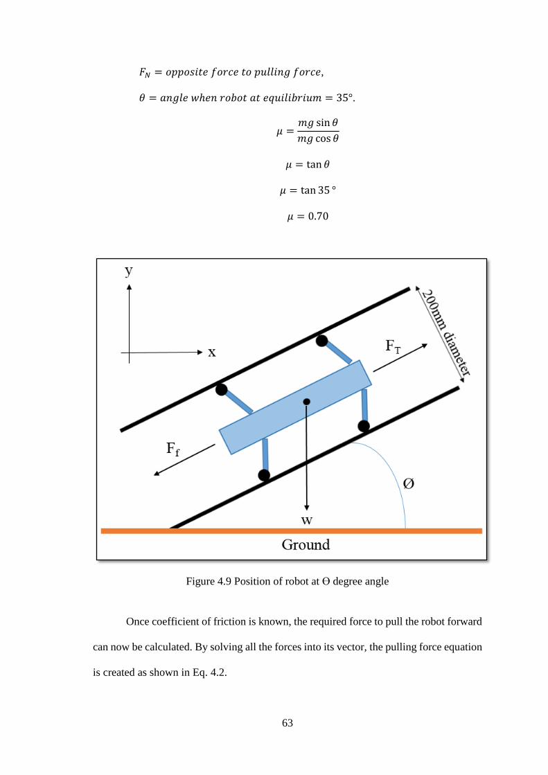
𝐹𝑁 = 𝑜𝑝𝑝𝑜𝑠𝑖𝑡𝑒 𝑓𝑜𝑟𝑐𝑒 𝑡𝑜 𝑝𝑢𝑙𝑙𝑖𝑛𝑔 𝑓𝑜𝑟𝑐𝑒,
𝜃 = 𝑎𝑛𝑔𝑙𝑒 𝑤ℎ𝑒𝑛 𝑟𝑜𝑏𝑜𝑡 𝑎𝑡 𝑒𝑞𝑢𝑖𝑙𝑖𝑏𝑟𝑖𝑢𝑚 = 35°.
𝜇 =
𝑚𝑔 sin 𝜃
𝑚𝑔 cos 𝜃
𝜇 = tan 𝜃
𝜇 = tan 35 °
𝜇 = 0.70
Figure 4.9 Position of robot at Ɵ degree angle
Once coefficient of friction is known, the required force to pull the robot forward
can now be calculated. By solving all the forces into its vector, the pulling force equation
is created as shown in Eq. 4.2.

64
𝐹𝑝 = 𝑚𝑔(sin 𝜃 + 𝜇 cos 𝜃) (4.2)
where 𝑚 = 𝑚𝑎𝑠𝑠 𝑜𝑓 𝑏𝑜𝑑𝑦,
𝑔 = 𝑎𝑐𝑐𝑒𝑙𝑒𝑟𝑎𝑡𝑖𝑜𝑛 𝑜𝑓 𝑔𝑟𝑎𝑣𝑖𝑡𝑦.
An assumption made to ease calculation is that all the calculation is only for 1
driving module. Then, the pulling force is calculated by substituting the angle values,
coefficient of friction, mass and acceleration of gravity into Eq. 4.2.
𝐹𝑝 = (1.53)(9.81)(sin 𝜃 + (0.70)cos 𝜃)
To calculate the torque of motor, Eq. 4.3 is used.
𝜏 = 𝐹𝑝. 𝑟 (4.3)
where 𝑟 = 𝑟𝑎𝑑𝑖𝑢𝑠 𝑜𝑓 𝑡ℎ𝑒 𝑤ℎ𝑒𝑒𝑙.
Based on chapter 3, diameter of the wheel is given as 32 mm. By using Eq. 4.2,
a table of motor force and motor torque is constructed for multiple slope angles ranging
from 35° to 90°. Table 4.2 shows the amount of motor force and torque required to move
forward in a pipe at 35° slope to 90° vertical pipe configuration in a 5° incremental.
Table 4.2: Motor force and motor torque required for slope more than 30degrees to
achieve equilibrium
Angle(°) Motor force, Fp (N) Motor Torque, 𝝉 (N.m) at equilibrium
35 17.2 0.275
40 17.7 0.283
45 18.0 0.288
50 18.3 0.293
55 18.3 0.293
60 18.3 0.293
65 18.0 0.288
70 17.7 0.283
75 17.2 0.275
80 16.6 0.266
85 15.9 0.254
90 15.0 0.240
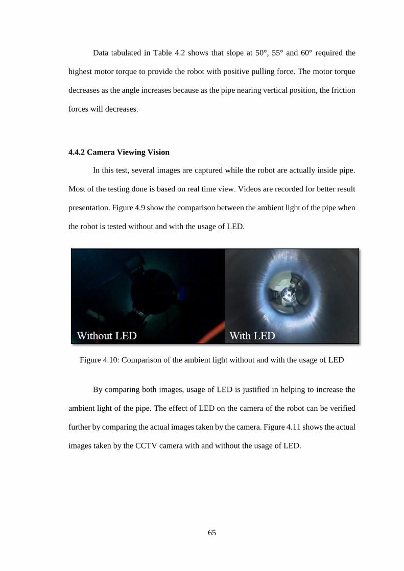
65
Data tabulated in Table 4.2 shows that slope at 50°, 55° and 60° required the
highest motor torque to provide the robot with positive pulling force. The motor torque
decreases as the angle increases because as the pipe nearing vertical position, the friction
forces will decreases.
4.4.2 Camera Viewing Vision
In this test, several images are captured while the robot are actually inside pipe.
Most of the testing done is based on real time view. Videos are recorded for better result
presentation. Figure 4.9 show the comparison between the ambient light of the pipe when
the robot is tested without and with the usage of LED.
Figure 4.10: Comparison of the ambient light without and with the usage of LED
By comparing both images, usage of LED is justified in helping to increase the
ambient light of the pipe. The effect of LED on the camera of the robot can be verified
further by comparing the actual images taken by the camera. Figure 4.11 shows the actual
images taken by the CCTV camera with and without the usage of LED.

66
Figure 4.11: Comparison of the actual images taken by the CCTV camera without and
with the usage of LED
The camera pan and tilt angle are limited by several factors that is servo motor
and hardware limitation. For this project, the camera are not able to rotate a full 90° to
both upwards and downwards position. To test the maximum angle the servo able to
rotate, an indicator is placed on top of the camera lens. Figure 4.12 shows the maximum
angle servo rotation. Rotation upward is limited to 63° while rotation downward is
limited to 70°. Rotation for horizontal movement are able to rotate both 90° left and right.
Figure 4.12: Servo maximum angle rotation
4.5 Real Time Performance Evaluation
The real time performance evaluation of this pipe inspection robot is done while
testing the robot moving in a pipe in multiple slope angles. The robot are easily able to
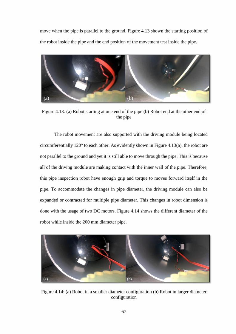
67
move when the pipe is parallel to the ground. Figure 4.13 shown the starting position of
the robot inside the pipe and the end position of the movement test inside the pipe.
Figure 4.13: (a) Robot starting at one end of the pipe (b) Robot end at the other end of
the pipe
The robot movement are also supported with the driving module being located
circumferentially 120° to each other. As evidently shown in Figure 4.13(a), the robot are
not parallel to the ground and yet it is still able to move through the pipe. This is because
all of the driving module are making contact with the inner wall of the pipe. Therefore,
this pipe inspection robot have enough grip and torque to moves forward itself in the
pipe. To accommodate the changes in pipe diameter, the driving module can also be
expanded or contracted for multiple pipe diameter. This changes in robot dimension is
done with the usage of two DC motors. Figure 4.14 shows the different diameter of the
robot while inside the 200 mm diameter pipe.
Figure 4.14: (a) Robot in a smaller diameter configuration (b) Robot in larger diameter
configuration
68
4.7 Summary
All of the robot components are successfully tested and functioned. However,
while testing, a few problems occurs. Most critical issues are the camera ambient light.
This is solved by equipping the robot with LED to increase the ambient light. Besides,
the mechanical strength of the whole system need to be improved. In short, testing of the
robot need to continuously done to identify more areas that can be improved until a
perfect pipe inspection robot is developed.
69
CHAPTER 5
CONCLUSION & FUTURE WORK
5.1 Conclusion
For this project, there are three objectives. The main and first objective is to
design, develop and fabricate a pipe inspection robot platform. After series of testing,
this objective has been achieved successfully. The robot build has a dimension of 542
mm in length and has a maximum diameter of 230 mm. The pipe inspection robot has 3
section to it. The first section is the camera section followed by front driving module
section and lastly the back driving module. The diameter of the robot can be varying
from 150 mm to 230 mm in diameter to accommodate pipe with unsymmetrical diameter
or when there is obstacles present inside the pipe. The robot is able to climb a slope with
maximum angle of 30 degrees. Camera system on this robot allow the camera view to be
rotated inside the pipe to monitor pipe condition more thoroughly.
The next objective of this project is to develop a reliable working program and
application to remotely control the robot operation. This objective has been accomplished
successfully. The robot are able to move in a 200 mm pipe diameter without any help
from the operator. The application are able to control the robot to move front and back
and adjusting its diameter. Functions of the application also allows images to be capture
directly from the camera and stored in PC. Videos are also able to be recorded for details
analysis. Furthermore, the application are also able to provide a live view of the robot
camera.
The last objective of this project is to test the pipe inspection robot system for
simple pipe inspection application. Unfortunately, this objectives are completely fulfilled
as the material used to fabricate the robot are not strong enough to withstand the force

70
provided by the DC motors. While testing on a steep angle, the driving module cannot
moves forward when the diameter of the robot are increase to provide the robot with grip
to hold it in place. Besides, when the diameter of the robot are larger than the pipe
diameter, it will clamp itself inside the pipe and won’t allow the robot to moves in any
direction. However, this proves that given a more powerful motor to drive the driving
module, the robot will almost certainly able to climb a vertical pipe configuration.
5.2 Future Works
Recommended future development for this pipe inspection robot include the
design of driving module. Size is very important for moving inside piping system.
Smaller driving module size and reduced number of module are needed to provide better
steering ability. Besides, sensors need to be included to automatically adjust the diameter
of the pipe inspection robot according to the piping size and pressure exerted to the pipe
wall. Furthermore, there is also a need for a leak sensor inside the driving module
compartment to detect any leakage. With this, operation of the pipe inspection robot can
be halted for safe retrieval of the robot. Finally, a more powerful micro motor need to be
developed to be equipped to this pipe inspection robot to allow it to climb pipe in vertical
position.
71
REFERENCES
[1] M. Z. Baharuddin, J. M. Saad, A. Anuar, I. N. Ismail, N. M. H. Basri, N. S.
Roslin, et al., "Robot for Boiler Header Inspection “LS-01”," Procedia
Engineering, vol. 41, pp. 1483-1489, // 2012.
[2] H. R. Choi and S. M. Ryew, "Robotic system with active steering capability for
internal inspection of urban gas pipelines," Mechatronics, vol. 12, pp. 713-736,
6// 2002.
[3] R. Se-gon and C. Hyouk Ryeol, "Differential-drive in-pipe robot for moving
inside urban gas pipelines," Robotics, IEEE Transactions on, vol. 21, pp. 1-17,
2005.
[4] S. G. Roh, S. M. Ryew, J. H. Yang, and H. R. Choi, "Actively steerable in-pipe
inspection robots for underground urban gas pipelines," in Robotics and
Automation, 2001. Proceedings 2001 ICRA. IEEE International Conference on,
2001, pp. 761-766 vol.1.
[5] Z. Liu and D. Krys, "The use of laser range finder on a robotic platform for pipe
inspection," Mechanical Systems and Signal Processing, vol. 31, pp. 246-257,
8// 2012.
[6] Z. Liu and Y. Kleiner, "State of the art review of inspection technologies for
condition assessment of water pipes," Measurement, vol. 46, pp. 1-15, 1// 2013.
[7] MHOBBIES.COM. Maximum Load 15KG 4WD robot chassis with 4 dc metal
motor [Online]. Available: http://www.mhobbies.com/maximum-load-15kg-
4wd-robot-chassis-with-4-dc-metal-motor.html [Accessed 4 February 2015.
[8] LABS, V. Forward Kinematics [Online]. Available: http://cse17-iiith.virtual-
labs.ac.in/forwardkinematics/index.php?section=Theory [Accessed January
2015.
[9] S. Fujiwara, R. Kanehara, T. Okada, and T. Sanemori, "An articulated multi-
vehicle robot for inspection and testing of pipeline interiors," in Intelligent
Robots and Systems '93, IROS '93. Proceedings of the 1993 IEEE/RSJ
International Conference on, 1993, pp. 509-516 vol.1.
[10] S. Linzhi, S. Ping, L. Li, Q. Xinjie, and G. Zhenbang, "Improvement of
characteristics of in-pipe micro robot," in Micromechatronics and Human
Science, 1999. MHS '99. Proceedings of 1999 International Symposium on,
1999, pp. 153-156.

72
[11] T. Fukuda, H. Hosokai, and N. Shimasaka, "Autonomous plant maintenance
robot (mechanism of Mark IV and its actuator characteristics)," in Intelligent
Robots and Systems '90. 'Towards a New Frontier of Applications',
Proceedings. IROS '90. IEEE International Workshop on, 1990, pp. 471-478
vol.1.
[12] J. Lim, H. Park, J. An, Y.-S. Hong, B. Kim, and B.-J. Yi, "One pneumatic line
based inchworm-like micro robot for half-inch pipe inspection," Mechatronics,
vol. 18, pp. 315-322, 9// 2008
[13] I. Hayashi, N. Iwatsuki, and S. Iwashina, "The running characteristics of a
screw-principle microrobot in a small bent pipe," in Micro Machine and Human
Science, 1995. MHS '95., Proceedings of the Sixth International Symposium on,
1995, pp. 225-228.
[14] S. Linzhi, S. Ping, L. Li, Q. Xinjie, and G. Zhenbang, "Improvement of
characteristics of in-pipe micro robot," in Micromechatronics and Human
Science, 1999. MHS '99. Proceedings of 1999 International Symposium on,
1999, pp. 153-156.
[15] www.arduino.cc. 2015. Arduino Micro [Online]. Arduino.cc. Available:
http://www.arduino.cc/en/Main/ArduinoBoardMicro [Accessed 20 December
2014].
[16] INSTRUMENTS, T. 1986. L293, L293D QUADRUPLE HALF_H DRIVERS
DATA SHEET. L293, L293D QUADRUPLE HALF_H DRIVERS. Revised
November 2004 ed.: Texas Instruments.
[17] SEMICONDUCTORS, N. 2015. 74HC595; 74HCT595 DATA SHEET. 8-bit
serial-in, serial or parallel-out shift register with output latches; 3-state. Rev. 7
ed.: NXP Semiconductors.
[18] TECHNOLOGIES, C. 298:1 Micro Metal Gearmotor [Online]. Available:
http://www.cytron.com.my/p-spg10-298k [Accessed 5 January 2015.
[19] TECHNOLOGIES, C. DC Geared Motor SPG30-60K [Online]. Available:
http://www.cytron.com.my/p-spg30-60k [Accessed 3 January 2015.
[20] PRO, T. MG90s Metal Gear Servo Data Sheet. MG90s Metal Gear Servo.
Tower Pro.
73
[21] JMK. Mini CMOS CCTV Camera [Online]. Available:
http://www.cctvcamerainchina.com/1-3-2-mini-cmos-cctv-camera-2.html
[Accessed 4 January 2015.
[22] SHIRRIFF, K. Secrets of Arduino PWM [Online]. Available:
http://www.arduino.cc/en/Tutorial/SecretsOfArduinoPWM 15 February 2015].
[23] TANTOS, A. 2011. H-Bridges [Online]. Available:
http://www.modularcircuits.com/blog/articles/h-bridge-secrets/h-bridges-the-
basics/ [Accessed 10 January 2015.
[24] TOOLBOX, T. E. Body Forces on Inclined Planes [Online]. Available:
http://www.engineeringtoolbox.com/inclined-planes-forces-d_1305.html
[Accessed May 2015.
Related Documents