FYP Presentation #04 Advisor: Dr. Khurram Imran Khan Co. Advisor: Dr. Roman Zaib Babar GROUP MEMBERS Ali Manshah 2013040 Izaz Ahsan 2013156 Obaid Ullah 2013297 DATE: February 1, 2017

Welcome message from author
This document is posted to help you gain knowledge. Please leave a comment to let me know what you think about it! Share it to your friends and learn new things together.
Transcript
FYP Presentation #04
Advisor: Dr. Khurram Imran KhanCo. Advisor: Dr. Roman Zaib Babar
GROUP MEMBERS
Ali Manshah 2013040Izaz Ahsan 2013156 Obaid Ullah 2013297
DATE: February 1, 2017
1. Introduction
2. Objectives
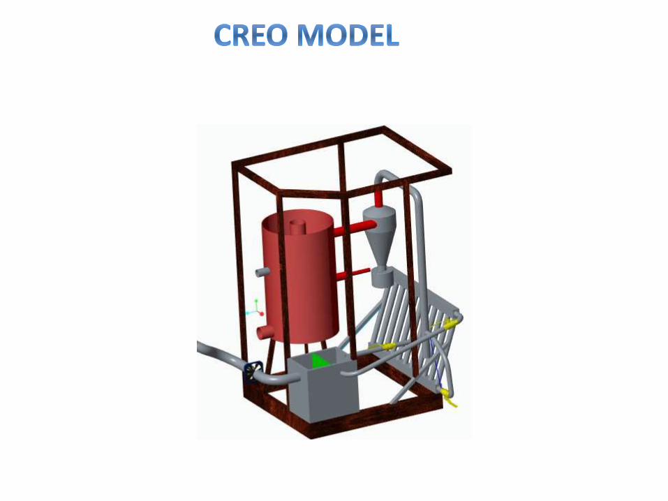
3. Fixed Bed Biomass Gasifier
4. Process Flow Diagram
5. Relative parameter for fire tube designing
6. Gasifier Different zone
7. Cyclone Separator
8. References
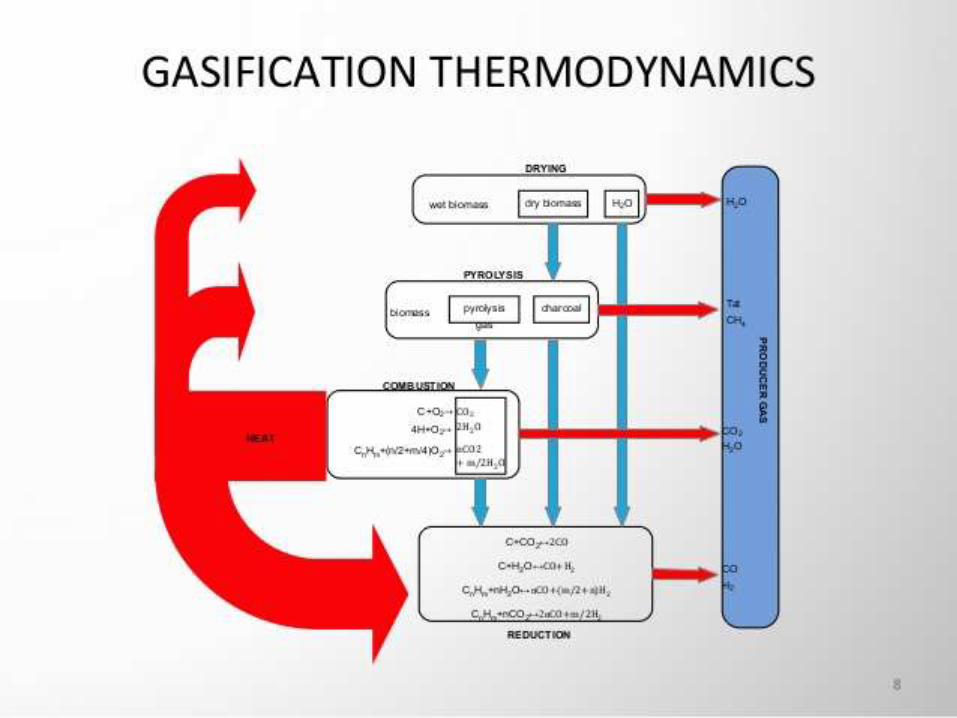
Biomass gasification is a chemical process that convert biomass into useful convenient gaseous fuel. It has emerged as a promising technology to fulfill the increasing energy demands of the world as well as to reduce significantly the volume of Biomass waste generated in developing societies.
Gasification produce gases like CO,CO2, H2 and CH4; these gas released are called Syngas.Gasification technology can be used for:1. Household Fuel2. Electricity and Steam Generation3. In internal combustion engines as a fuelIn a gasifier, the biomass undergoes several different processes like drying, pyrolysis, combustion and gasification process
Fabrication of biomass gasifier unit totransfer solid fuels into gaseous fuel.
Simulation of biomass gasification unit forfinding the optimum parameters of theprocess.
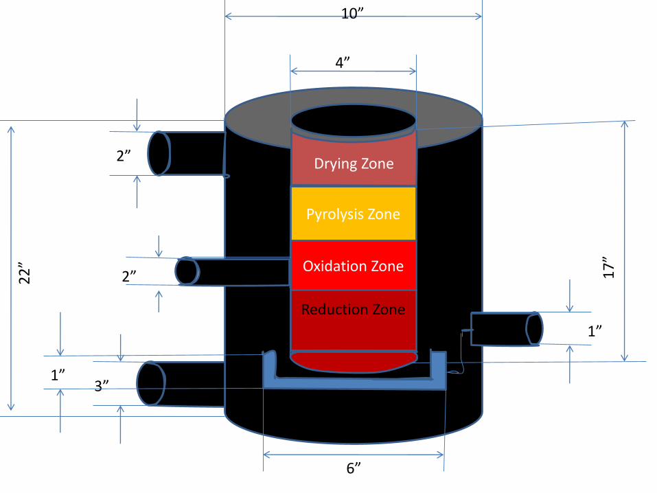
Drying Zone
Oxidation Zone
Pyrolysis Zone
Reduction Zone
22
”
2”
2”
3”
4”
10”
17
”
1”
6”
1”
Ash-pit
Drying Zone
Oxidation Zone
Pyrolysis Zone
Reduction Zone
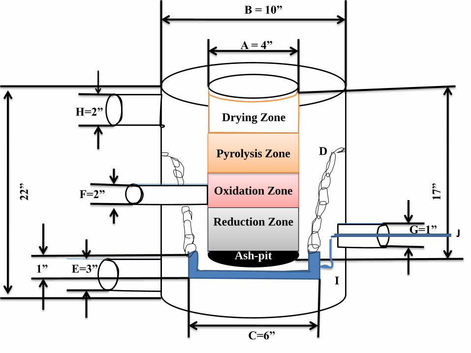
22”
H=2”
F=2”
E=3”
A = 4”
B = 10”
17”
G=1”
C=6”
1”
D
I
J
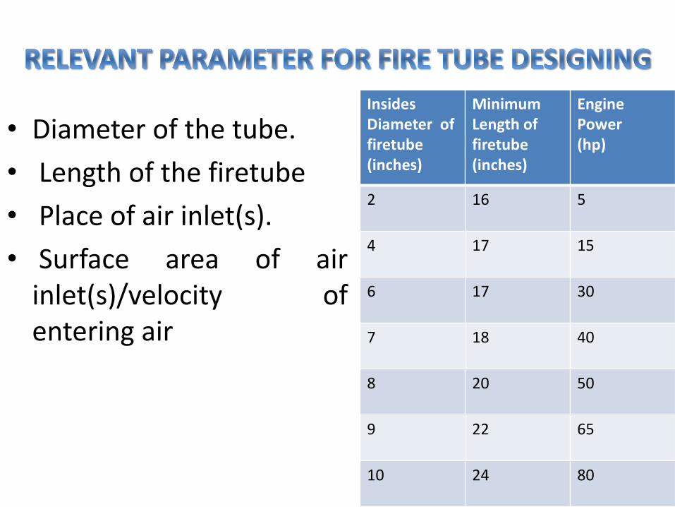
• Diameter of the tube.
• Length of the firetube
• Place of air inlet(s).
• Surface area of airinlet(s)/velocity ofentering air
Insides Diameter of firetube(inches)
Minimum Length of firetube(inches)
Engine Power(hp)
2 16 5
4 17 15
6 17 30
7 18 40
8 20 50
9 22 65
10 24 80
1. DRYING ZONE
• The topmost zone contains unreacted biomass (fuel)through which air and oxygen enters. This zone act as adrying zone for fuel.
• Biomass fuels usually contain 10%–35% moisture. Whenbiomass is heated to about 100 °C, the moisture isconverted into steam.
• At temperatures above 250°C, the biomass fuelstarts pyrolysing. The details of these pyrolysisreactions are not well known, but one can guessthat large molecules (such as cellulose, hemi-cellulose and lignin) break down into mediumsize molecules and carbon (char) during theheating of the feedstock.
• The pyrolysis products flow downwards into thehotter zones of the gasifier. Some will be burned inthe oxidation zone, and the rest will break down toeven smaller molecules of hydrogen, methane,carbon monoxide, carbon dioxide, water etc.
• Biomass + O2 → Char+CO+H2+H2O+CO2+CH4+N2
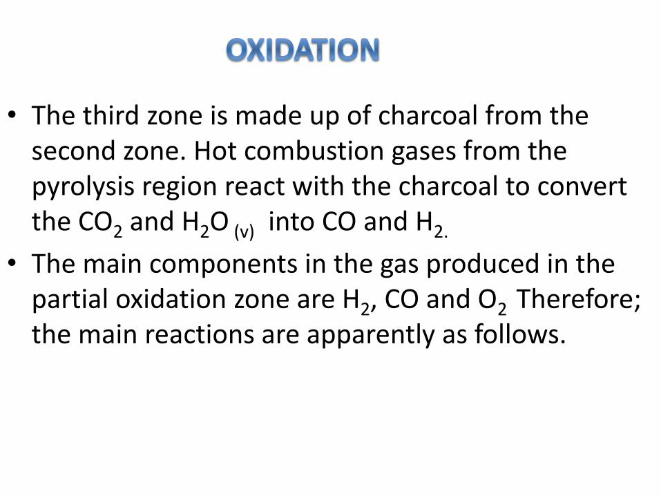
• The third zone is made up of charcoal from the second zone. Hot combustion gases from the pyrolysis region react with the charcoal to convert the CO2 and H2O (v) into CO and H2.
• The main components in the gas produced in the partial oxidation zone are H2, CO and O2 Therefore; the main reactions are apparently as follows.
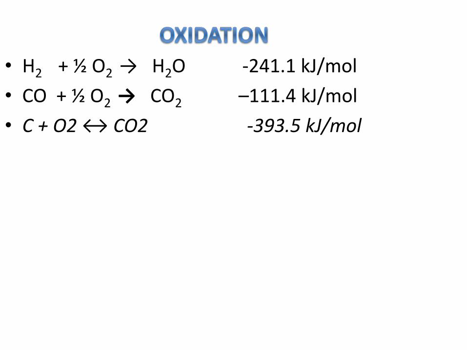
• H2 + ½ O2 → H2O -241.1 kJ/mol
• CO + ½ O2 → CO2 –111.4 kJ/mol
• C + O2 ↔ CO2 -393.5 kJ/mol
• The reaction products of the oxidation zone (hotgases and glowing charcoal) move downward intothe reduction zone.
• In this zone the sensible heat of the gases andcharcoal is converted as much as possible intochemical energy of the syngas. The end product ofthe chemical reactions that take place in thereduction zone is a combustible gas which can beused as fuel gas in burners and after dust removaland cooling is suitable for internal combustionengines.
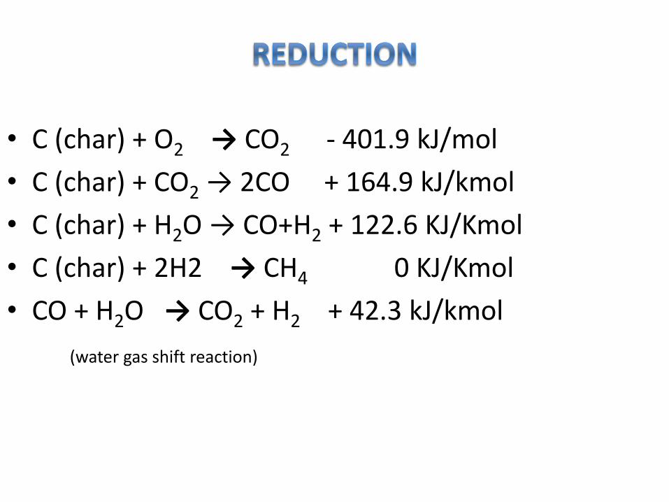
• C (char) + O2 → CO2 - 401.9 kJ/mol
• C (char) + CO2 → 2CO + 164.9 kJ/kmol
• C (char) + H2O → CO+H2 + 122.6 KJ/Kmol
• C (char) + 2H2 → CH4 0 KJ/Kmol
• CO + H2O → CO2 + H2 + 42.3 kJ/kmol
(water gas shift reaction)
• DESCRIPTION
• This is the separator mainly used for the separationof solids from the fluids. It mainly consists of thetangential inlet to feed the materials inside thechamber.
• It consists of solids out let and fluid out let, itthrough the fluid through one side and theseparated solids through the other out let.
• PRINCIPLE
• In the cyclone separator the centrifugal force isused to separate tar, dust and solid particles fromthe syngas. The separation depends not only on theparticles size but also on the density of theparticles.
• Hence depending on the syngas velocity the cycloneseparator can be used to separate all types of theparticles, out to remove, and allows fine particles tobe carried through with the fluid.
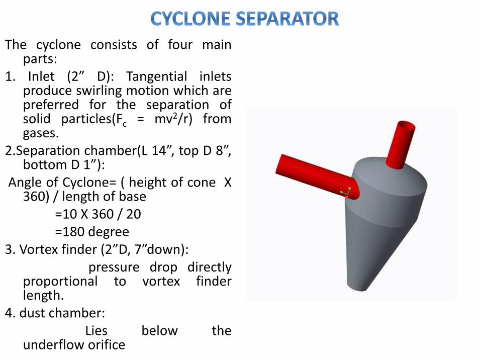
The cyclone consists of four mainparts:
1. Inlet (2” D): Tangential inletsproduce swirling motion which arepreferred for the separation ofsolid particles(Fc = mv2/r) fromgases.
2.Separation chamber(L 14”, top D 8”,bottom D 1”):
Angle of Cyclone= ( height of cone X360) / length of base
=10 X 360 / 20=180 degree
3. Vortex finder (2”D, 7”down):pressure drop directly
proportional to vortex finderlength.
4. dust chamber:Lies below the
underflow orifice
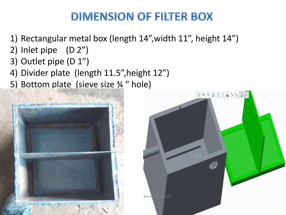
1) Rectangular metal box (length 14”,width 11”, height 14”)2) Inlet pipe (D 2”)3) Outlet pipe (D 1”)4) Divider plate (length 11.5”,height 12”)5) Bottom plate (sieve size ¾ “ hole)
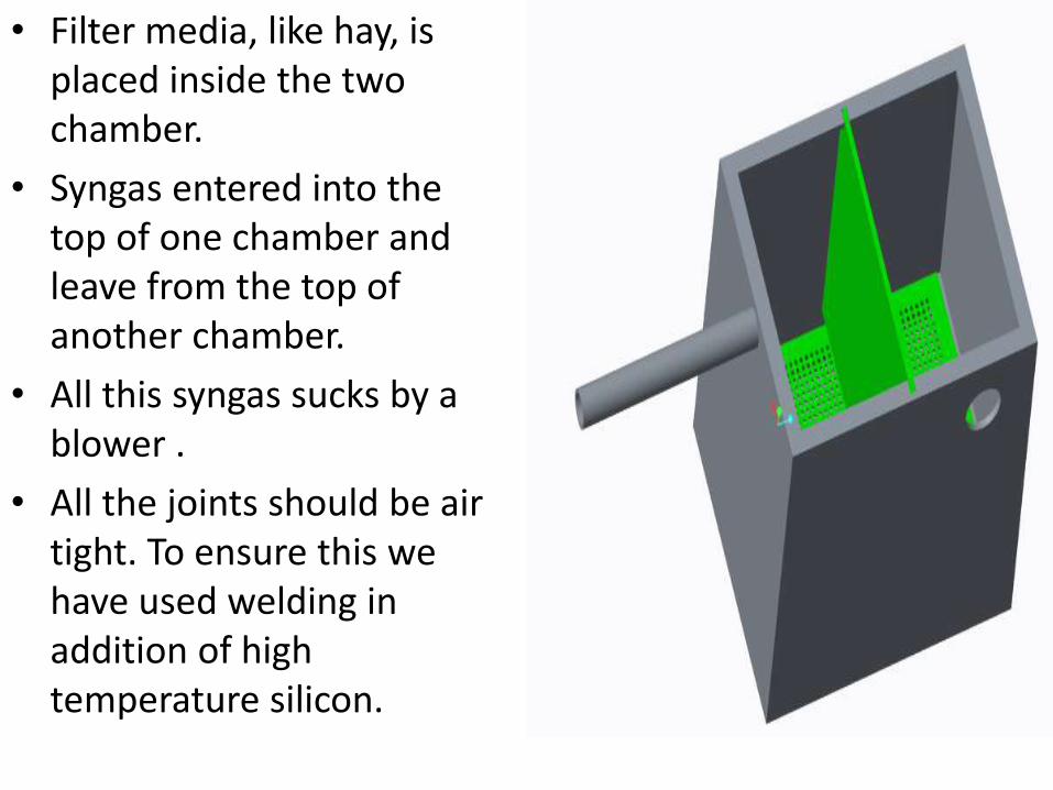
• Filter media, like hay, is placed inside the two chamber.
• Syngas entered into the top of one chamber and leave from the top of another chamber.
• All this syngas sucks by a blower .
• All the joints should be air tight. To ensure this we have used welding in addition of high temperature silicon.
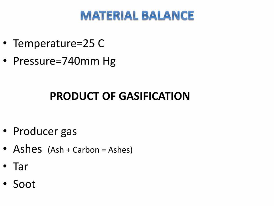
• Temperature=25 C
• Pressure=740mm Hg
PRODUCT OF GASIFICATION
• Producer gas
• Ashes (Ash + Carbon = Ashes)
• Tar
• Soot
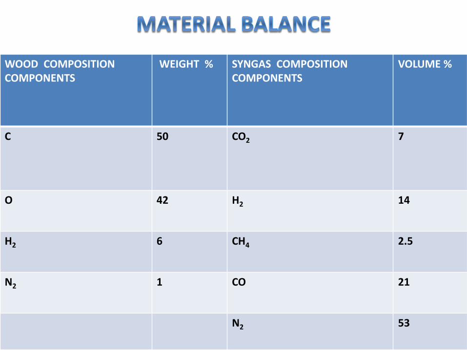
WOOD COMPOSITION COMPONENTS
WEIGHT % SYNGAS COMPOSITIONCOMPONENTS
VOLUME %
C 50 CO2 7
O 42 H2 14
H2 6 CH4 2.5
N2 1 CO 21
N2 53
• The substance of a solid fuel is usually composedof the elements C, H2 and O2.
• In addition there may be N2 and S, but since theseare present only in small quantities they will bedisregarded in the following discussion.
• In the type of gasifiers considered here, a part ofthe solid fuel is heated by combustion. Thecombustion gases are then reduced by beingpassed through a bed of fuel at high temperature.
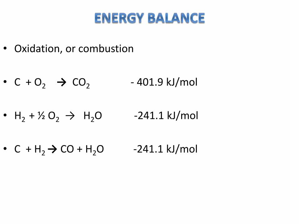
• Oxidation, or combustion
• C + O2 → CO2 - 401.9 kJ/mol
• H2 + ½ O2 → H2O -241.1 kJ/mol
• C + H2 → CO + H2O -241.1 kJ/mol
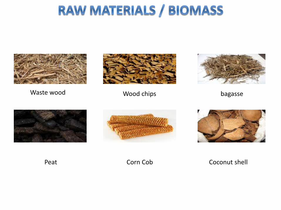
Waste wood Wood chips bagasse
Peat Corn Cob Coconut shell
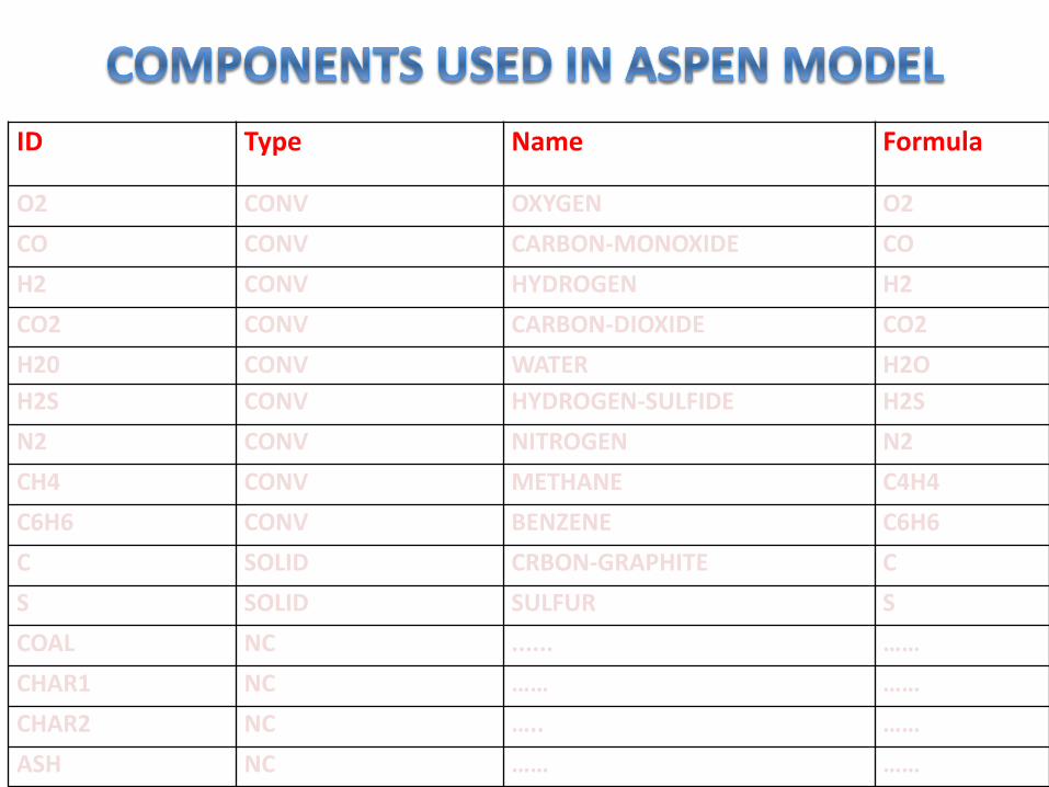
ID Type Name Formula
O2 CONV OXYGEN O2
CO CONV CARBON-MONOXIDE CO
H2 CONV HYDROGEN H2
CO2 CONV CARBON-DIOXIDE CO2
H20 CONV WATER H2O
H2S CONV HYDROGEN-SULFIDE H2S
N2 CONV NITROGEN N2
CH4 CONV METHANE C4H4
C6H6 CONV BENZENE C6H6
C SOLID CRBON-GRAPHITE C
S SOLID SULFUR S
COAL NC ...... ……
CHAR1 NC …… ……
CHAR2 NC ….. ……
ASH NC …… ……
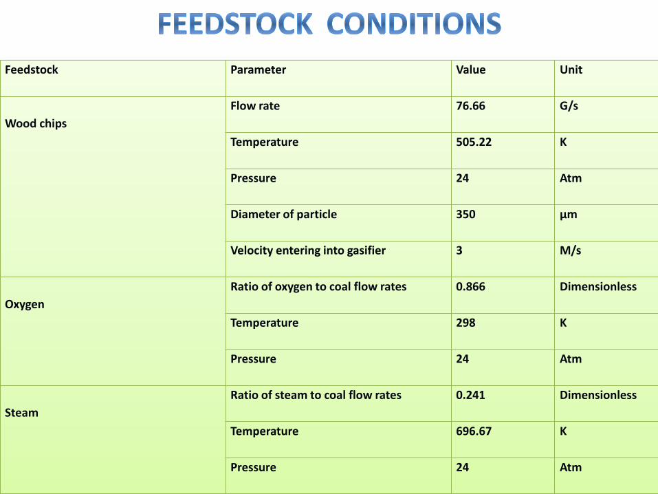
Feedstock Parameter Value Unit
Wood chips
Flow rate 76.66 G/s
Temperature 505.22 K
Pressure 24 Atm
Diameter of particle 350 µm
Velocity entering into gasifier 3 M/s
Oxygen
Ratio of oxygen to coal flow rates 0.866 Dimensionless
Temperature 298 K
Pressure 24 Atm
Steam
Ratio of steam to coal flow rates 0.241 Dimensionless
Temperature 696.67 K
Pressure 24 Atm

Yield of Wood Pyrolysis used in the model
Pressure(1atm) Pressure(24atm)
Components Yield(mass basis) Yield(mass basis)
CO 0.0059 0.0055
H2 0.0084 0.0080
CO2 0.003 0.00286
H2O 0.0079 0.00747
H2S 0.0094 0.0087
N2 0.0035 0.00347
CH4 0.1637 0.1601
C6H6 0.071 0.0701
Char 0.7272 0.7201
Total 1 1
0
10
20
30
40
50
60
70
650 700 750 800
Mo
lar
Co
mp
osi
tio
n (
%)
Temp (°C)
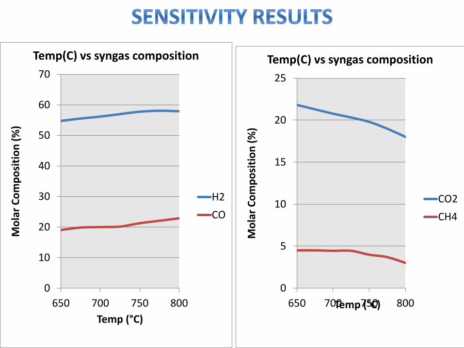
Temp(C) vs syngas composition
H2
CO
0
5
10
15
20
25
650 700 750 800
Mo
lar
Co
mp
osi
tio
n (
%)
Temp (°C)
Temp(C) vs syngas composition
CO2
CH4
0
10
20
30
40
50
60
70
0 1 2 3
Pe
rce
nta
ge o
f co
mp
osi
tio
n
Steam to biomass ratio
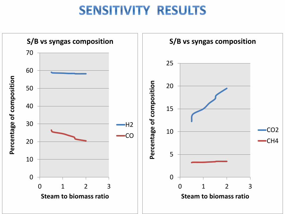
S/B vs syngas composition
H2
CO
0
5
10
15
20
25
0 1 2 3
Pe
rce
nta
ge o
f co
mp
osi
tio
n
Steam to biomass ratio
S/B vs syngas composition
CO2
CH4
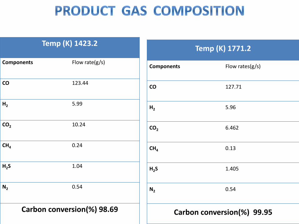
Temp (K) 1423.2
Components Flow rate(g/s)
CO 123.44
H2 5.99
CO2 10.24
CH4 0.24
H2S 1.04
N2 0.54
Carbon conversion(%) 98.69
Temp (K) 1771.2
Components Flow rates(g/s)
CO 127.71
H2 5.96
CO2 6.462
CH4 0.13
H2S 1.405
N2 0.54
Carbon conversion(%) 99.95
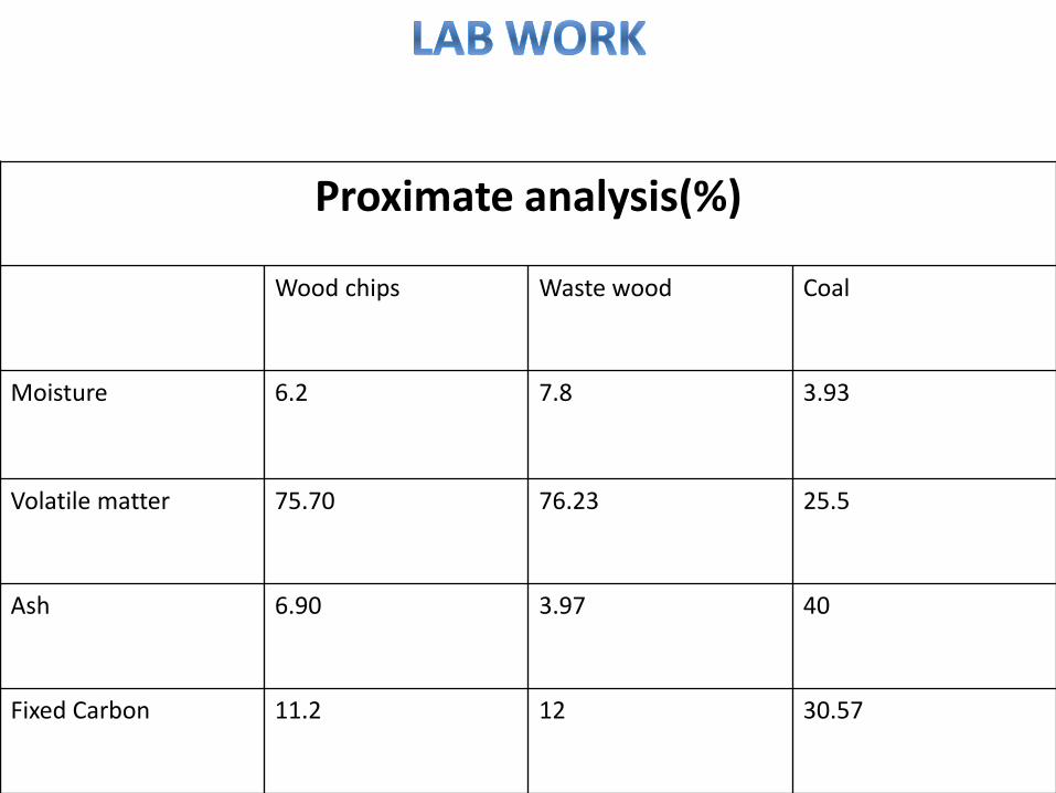
Proximate analysis(%)
Wood chips Waste wood Coal
Moisture 6.2 7.8 3.93
Volatile matter 75.70 76.23 25.5
Ash 6.90 3.97 40
Fixed Carbon 11.2 12 30.57
• LaFontaine, H., & Zimmerman, G. P. (1989). Construction of a simplified wood gas generator for fueling internal combustion engines in a petroleum emergency (No. ORNL-6404).OAK RIDGE NATIONAL LAB TN.
• Bhavanam, A., &Sastry, R. C. (2011). Biomass Gasification Processes in Downd raft Fixed Bed Reactors: A Review. International Journal of Chemical Engineering and Applications, 2(6), 425.
• Joshi, R., &Kulkarni, B. (2012).Simulation of biomass gasification reactor for fuel in gas turbine. International Journal of Chemical Sciences and Applications, 3, 232-240.
• Jayah, T. H., Aye, L., Fuller, R. J., & Stewart, D. F. Simulation Study of a Down-Draft Wood Gasifier Used to Produce Thermal Energy for Tea Drying.Renewable Energy Transforming Business, 639-646.

Related Documents