(English) DM-FC0002-12 ROAD MTB Trekking Bottom bracket SORA FC-3503 FC-3550 Claris FC-2403 FC-2450 Non-Series FC-R350 FC-RS200 FC-RS500 Tourney A070 FC-A070 FC-A073 DEORE XT FC-M780 FC-M782 FC-M785 FC-M8000 SLX FC-M670 FC-M672 FC-M675 FC-M677 ZEE FC-M640 FC-M645 DEORE FC-M610 FC-M612 FC-M615 FC-M617 ALIVIO FC-M4000 FC-M4050 FC-M4060 Tourney FC-TX801 FC-TY701 ACERA FC-M3000 FC-M3000-8 Non-Series FC-M351 FC-M371 FC-M522 FC-M523 FC-M552 FC-M622 FC-M625 FC-M627 FC-MT700 DEORE XT FC-T780 FC-T781 DEORE LX FC-T671 DEORE FC-T611 ACERA FC-T3010 FC-T3010-8 ALIVIO FC-T4010 FC-T4060 Non-Series FC-T521 Comfort ALFINE FC-S501 NEXUS FC-C6000 SM-BB52 SM-BB93 SM-BB94-41A SM-BB72 SM-BBR60 BB-UN100 BB-ES300 BB-MT500-PA BB-MT800 BB-MT800-PA BB-RS500 BB-RS500-PB Dealer's Manual ROAD MTB Trekking City Touring/ Comfort Bike URBAN SPORT E-BIKE Front chainwheel

Welcome message from author
This document is posted to help you gain knowledge. Please leave a comment to let me know what you think about it! Share it to your friends and learn new things together.
Transcript

(English) DM-FC0002-12
ROAD MTB Trekking Bottom bracketSORAFC-3503FC-3550
ClarisFC-2403FC-2450
Non-SeriesFC-R350FC-RS200FC-RS500
Tourney A070FC-A070FC-A073
DEORE XTFC-M780FC-M782FC-M785FC-M8000
SLXFC-M670FC-M672FC-M675FC-M677
ZEEFC-M640FC-M645
DEOREFC-M610FC-M612FC-M615FC-M617
ALIVIOFC-M4000FC-M4050FC-M4060
TourneyFC-TX801FC-TY701
ACERAFC-M3000FC-M3000-8
Non-SeriesFC-M351FC-M371FC-M522FC-M523FC-M552FC-M622FC-M625FC-M627FC-MT700
DEORE XTFC-T780FC-T781
DEORE LXFC-T671
DEOREFC-T611
ACERAFC-T3010FC-T3010-8
ALIVIOFC-T4010FC-T4060
Non-SeriesFC-T521
ComfortALFINEFC-S501
NEXUSFC-C6000
SM-BB52SM-BB93SM-BB94-41ASM-BB72SM-BBR60BB-UN100BB-ES300BB-MT500-PABB-MT800BB-MT800-PABB-RS500BB-RS500-PB
Dealer's Manual
ROAD MTB Trekking
City Touring/ Comfort Bike
URBAN SPORT E-BIKE
Front chainwheel
2
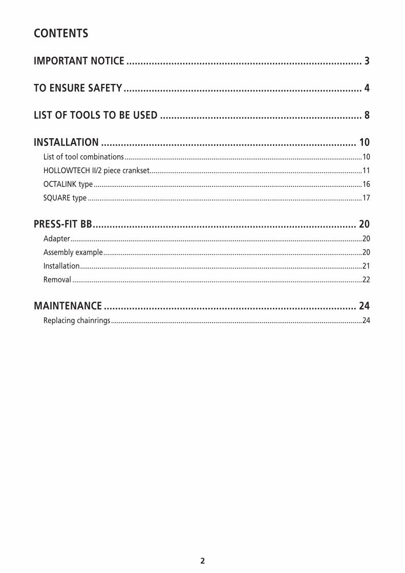
CONTENTS
IMPORTANT NOTICE .................................................................................... 3
TO ENSURE SAFETY ..................................................................................... 4
LIST OF TOOLS TO BE USED ........................................................................ 8
INSTALLATION ........................................................................................... 10List of tool combinations ...........................................................................................................................10
HOLLOWTECH II/2 piece crankset ..............................................................................................................11
OCTALINK type ...........................................................................................................................................16
SQUARE type ..............................................................................................................................................17
PRESS-FIT BB .............................................................................................. 20Adapter .......................................................................................................................................................20
Assembly example ......................................................................................................................................20
Installation ..................................................................................................................................................21
Removal ......................................................................................................................................................22
MAINTENANCE .......................................................................................... 24Replacing chainrings ..................................................................................................................................24

3
IMPORTANT NOTICE
IMPORTANT NOTICE
• This dealer’s manual is intended primarily for use by professional bicycle mechanics. Users who are not professionally trained for bicycle assembly should not attempt to install the components themselves using the dealer’s manuals. If any part of the information on the manual is unclear to you, do not proceed with the installation. Instead, contact your place of purchase or a local bicycle dealer for their assistance.
• Make sure to read all instruction manuals included with the product.
• Do not disassemble or modify the product other than as stated in the information contained in this dealer’s manual.
• All dealer’s manuals and instruction manuals can be viewed on-line on our website (http://si.shimano.com).
• Please observe the appropriate rules and regulations of the country, state or region in which you conduct your business as a dealer.
For safety, be sure to read this dealer’s manual thoroughly before use, and follow it for correct use.
The following instructions must be observed at all times in order to prevent personal injury and physical damage to equipment and surroundings.The instructions are classified according to the degree of danger or damage which may occur if the product is used incorrectly.
DANGER
Failure to follow the instructions will result in death or serious injury.
WARNING
Failure to follow the instructions could result in death or serious injury.
CAUTION
Failure to follow the instructions could cause personal injury or physical damage to equipment and surroundings.
4
TO ENSURE SAFETY
TO ENSURE SAFETY
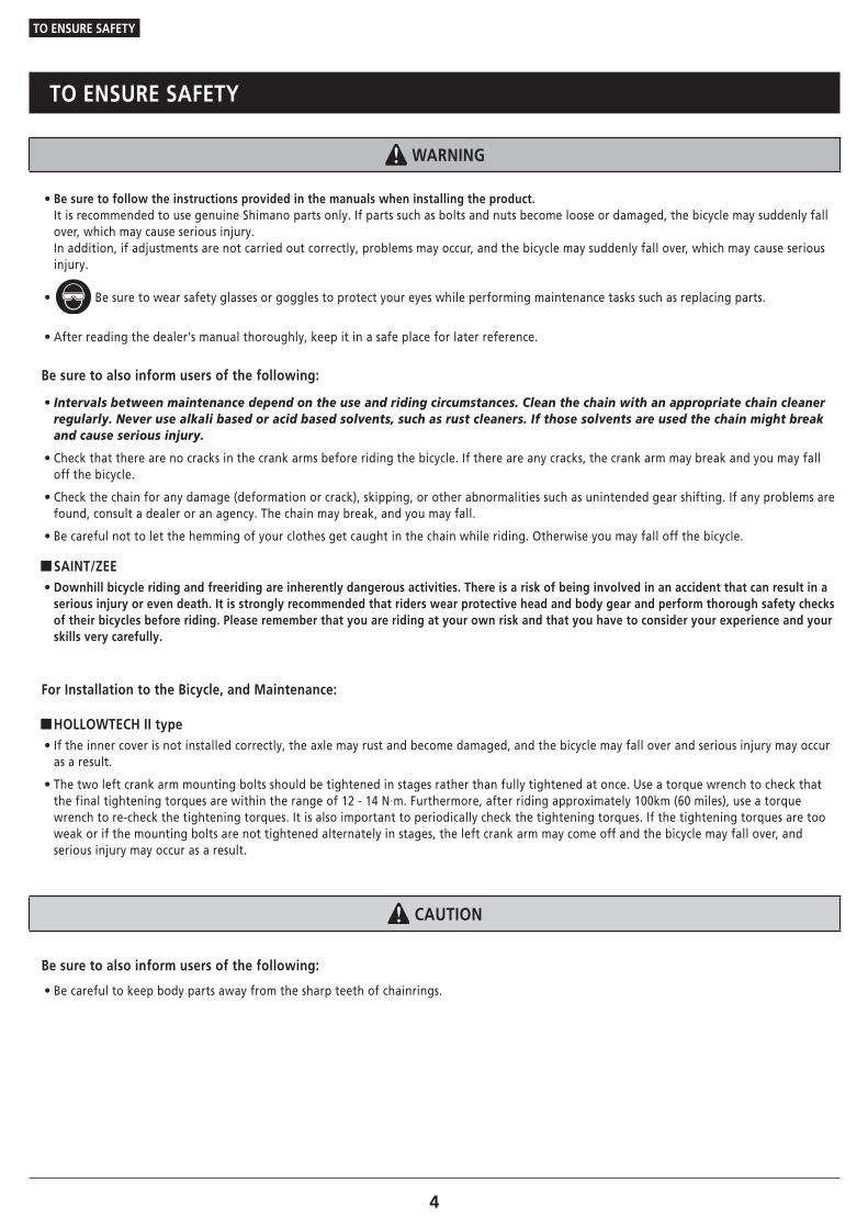
WARNING
• Be sure to follow the instructions provided in the manuals when installing the product.It is recommended to use genuine Shimano parts only. If parts such as bolts and nuts become loose or damaged, the bicycle may suddenly fall over, which may cause serious injury.In addition, if adjustments are not carried out correctly, problems may occur, and the bicycle may suddenly fall over, which may cause serious injury.
• Be sure to wear safety glasses or goggles to protect your eyes while performing maintenance tasks such as replacing parts.
• After reading the dealer's manual thoroughly, keep it in a safe place for later reference.
Be sure to also inform users of the following:
• Intervals between maintenance depend on the use and riding circumstances. Clean the chain with an appropriate chain cleaner regularly. Never use alkali based or acid based solvents, such as rust cleaners. If those solvents are used the chain might break and cause serious injury.
• Check that there are no cracks in the crank arms before riding the bicycle. If there are any cracks, the crank arm may break and you may fall off the bicycle.
• Check the chain for any damage (deformation or crack), skipping, or other abnormalities such as unintended gear shifting. If any problems are found, consult a dealer or an agency. The chain may break, and you may fall.
• Be careful not to let the hemming of your clothes get caught in the chain while riding. Otherwise you may fall off the bicycle.
�SAINT/ZEE • Downhill bicycle riding and freeriding are inherently dangerous activities. There is a risk of being involved in an accident that can result in a serious injury or even death. It is strongly recommended that riders wear protective head and body gear and perform thorough safety checks of their bicycles before riding. Please remember that you are riding at your own risk and that you have to consider your experience and your skills very carefully.
For Installation to the Bicycle, and Maintenance:
�HOLLOWTECH II type • If the inner cover is not installed correctly, the axle may rust and become damaged, and the bicycle may fall over and serious injury may occur as a result.
• The two left crank arm mounting bolts should be tightened in stages rather than fully tightened at once. Use a torque wrench to check that the final tightening torques are within the range of 12 - 14 N·m. Furthermore, after riding approximately 100km (60 miles), use a torque wrench to re-check the tightening torques. It is also important to periodically check the tightening torques. If the tightening torques are too weak or if the mounting bolts are not tightened alternately in stages, the left crank arm may come off and the bicycle may fall over, and serious injury may occur as a result.
CAUTION
Be sure to also inform users of the following:
• Be careful to keep body parts away from the sharp teeth of chainrings.
5
TO ENSURE SAFETY
NOTE
Be sure to also inform users of the following:
• Before riding the bicycle, check that there is no play or looseness between connecting parts. Also, be sure to retighten the crank and pedals at periodic intervals.
• Be sure to keep turning the crank arm during the lever operation.
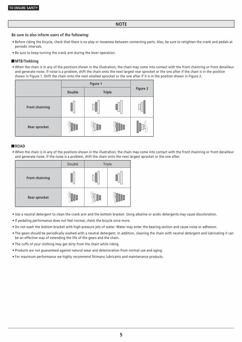
�MTB/Trekking • When the chain is in any of the positions shown in the illustration, the chain may come into contact with the front chainring or front derailleur and generate noise. If noise is a problem, shift the chain onto the next largest rear sprocket or the one after if the chain is in the position shown in Figure 1. Shift the chain onto the next smallest sprocket or the one after if it is in the position shown in Figure 2.
Figure 1Figure 2
Double Triple
Front chainring
Rear sprocket
�ROAD • When the chain is in any of the positions shown in the illustration, the chain may come into contact with the front chainring or front derailleur and generate noise. If the noise is a problem, shift the chain onto the next largest sprocket or the one after.
Double Triple
Front chainring
Rear sprocket
• Use a neutral detergent to clean the crank arm and the bottom bracket. Using alkaline or acidic detergents may cause discoloration.
• If pedaling performance does not feel normal, check the bicycle once more.
• Do not wash the bottom bracket with high-pressure jets of water. Water may enter the bearing section and cause noise or adhesion.
• The gears should be periodically washed with a neutral detergent. In addition, cleaning the chain with neutral detergent and lubricating it can be an effective way of extending the life of the gears and the chain.
• The cuffs of your clothing may get dirty from the chain while riding.
• Products are not guaranteed against natural wear and deterioration from normal use and aging.
• For maximum performance we highly recommend Shimano lubricants and maintenance products.
6
TO ENSURE SAFETY
For Installation to the Bicycle, and Maintenance:
• When installing the pedals, apply a small amount of grease to the threads to prevent the pedals from sticking. Use a torque wrench to securely tighten the pedals. Tightening torque: 35 - 55 N·m. The right-hand crank arm has a right-hand thread, and the left-hand crank arm has a left-hand thread.
• If the bottom bracket shell is not parallel, gear shifting performance will drop.
• If the chain keeps coming off the gears during use, replace the gears and the chain.
�HOLLOWTECH II/2 piece crank • When installing the left and right adapters, apply grease and be sure to install the inner cover. Otherwise the waterproofing performance will worsen.
• To ensure the best performance, be sure to use only the specified type of chain.
• If a squeaking noise is heard coming from the bottom bracket axle and the left crank arm connector, apply grease to the connector and then tighten it to the specified torque.
• If you feel any looseness in the bearings, the bottom bracket should be replaced.
• Be sure to use the specified gear tooth combination. If an unspecified gear is used, the dimension between the gears changes, and the chain may fall in between the gears.
�OCTALINK type/SQUARE type • Be sure to use only the applicable chain and bottom bracket.
• Apply grease to the bottom bracket before installing it.
• If you feel any looseness in the bottom bracket axle, the bottom bracket should be replaced.
�FC-M8000-B1/FC-M8000-B2 • Use FC-M8000-B1/FC-M8000-B2 with a specially designed frame.
The actual product may differ from the illustration because this manual is intended mainly to explain the procedures for using the product.

LIST OF TOOLS TO BE USED

8
LIST OF TOOLS TO BE USED
LIST OF TOOLS TO BE USED
The following tools are needed for installation, adjustment, and maintenance purposes.
Tool Tool Tool
5mm hexagon wrench TL-FC10 TL-FC36
8mm hexagon wrench TL-FC11 TL-FC37
10mm hexagon wrench TL-FC16 TL-BB12
15mm spanner TL-FC18 TL-BB13
16mm spanner TL-FC24 TL-UN66
17mm spanner TL-FC25 TL-UN74-S
19mm spanner TL-FC31 Hexalobular[#27]
32mm spanner TL-FC32 Hexalobular[#30]
Adjustable wrench TL-FC33
Plastic mallet TL-FC34

INSTALLATION

INSTALLATION
List of tool combinations
10
INSTALLATION
� List of tool combinationsUse the tools in the correct combination.
SM-BB93
TL-FC24 & TL-FC32 TL-FC24 & TL-FC33
TL-FC24
TL-FC32
TL-FC33TL-FC24
TL-FC24 & TL-FC36 TL-FC34
TL-FC24
TL-FC36
NOTE
• For an impact wrench, use TL-FC34 for SM-BB93. Use TL-FC37 for SM-BBR60/BB-MT800. Using other tools may damage the tool.
• TL-FC24/FC25 may become damaged and unusable after repeated use.
• When setting TL-FC24/FC25 in TL-FC32, check the possible setting position.
When setting in TL-FC32, check the possible setting position.
• Any position is possible when setting to TL-FC33/FC36.
SM-BBR60/BB-MT800
TL-FC25 & TL-FC32 TL-FC25 & TL-FC33
TL-FC25
TL-FC32
TL-FC33TL-FC25
TL-FC25 & TL-FC36 TL-FC37
TL-FC25
TL-FC36
INSTALLATION
HOLLOWTECH II/2 piece crankset
11To be continued on next page
� HOLLOWTECH II/2 piece crankset
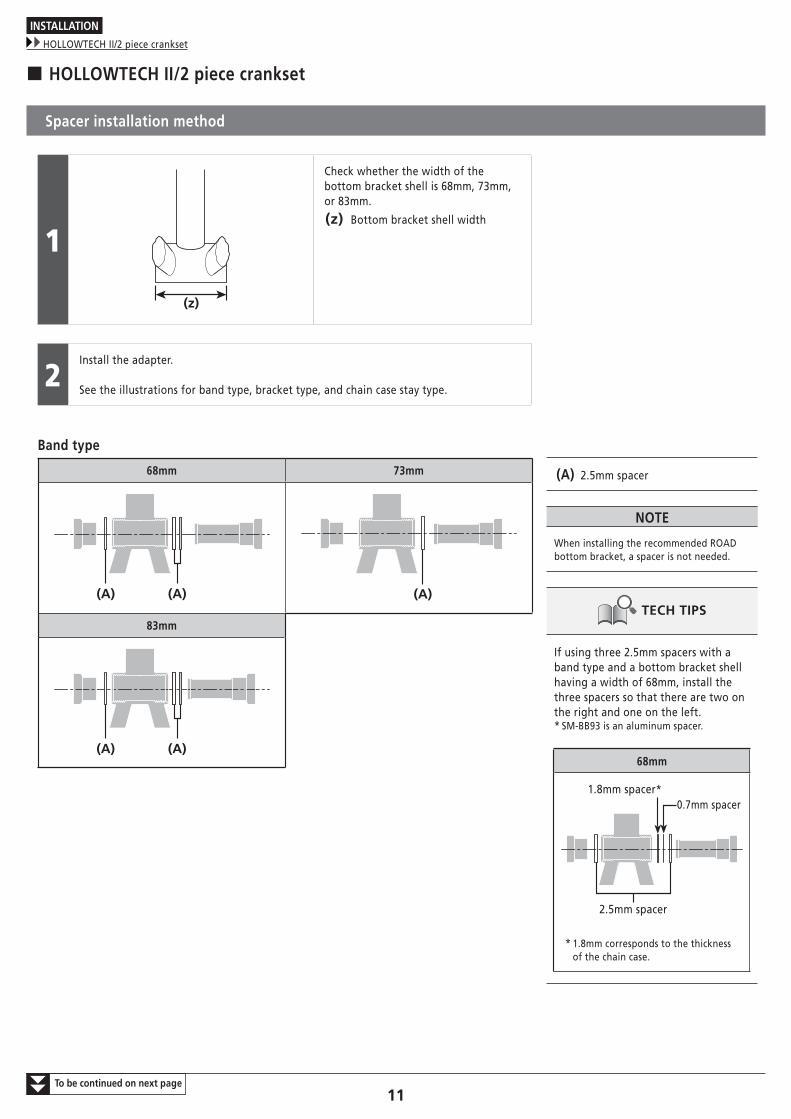
Spacer installation method
1
(z)
Check whether the width of the bottom bracket shell is 68mm, 73mm, or 83mm.
(z) Bottom bracket shell width
2Install the adapter.
See the illustrations for band type, bracket type, and chain case stay type.
Band type
68mm 73mm
(A) (A) (A)
83mm
(A) (A)
(A) 2.5mm spacer
NOTE
When installing the recommended ROAD bottom bracket, a spacer is not needed.
TECH TIPS
If using three 2.5mm spacers with a band type and a bottom bracket shell having a width of 68mm, install the three spacers so that there are two on the right and one on the left.* SM-BB93 is an aluminum spacer.
68mm
0.7mm spacer1.8mm spacer*
2.5mm spacer
* 1.8mm corresponds to the thickness of the chain case.

INSTALLATION
HOLLOWTECH II/2 piece crankset
12
Bracket type
68mm 73mm
(B)
(A)(B) (A)
83mm
(B)
(A)(B)
(A) BB mount-type bracket
(B) 2.5mm spacer
Chain case stay type
68mm 73mm
(A)
(B)
(C) (A) (C)
(A) Chain case stay
(B) 2.5mm spacer
(C) 0.7mm spacer
NOTE
If not using a chain case, use a 1.8mm spacer.

INSTALLATION
HOLLOWTECH II/2 piece crankset
13To be continued on next page
Installation of the crank
1
(A)
(D) (E)
(B) (C)
Grease the left and right hand adapters and use the Shimano original tool to install the right hand adapter of the bottom bracket, the inner cover and the left hand adapter of the bottom bracket.
(A) TL-FC32
(B) Inner cover
(C) Right hand adapter (counterclockwise thread) (for 70mm [M36], turn clockwise (clockwise thread))
(D) Left hand adapter (clockwise thread)
(E) Apply grease: Premium grease (Y-04110000)
Tightening torque
35 - 50 N·m
NOTE
TL-FC24/FC25 are tightened by combining with TL-FC32/FC36.
2
Insert the right crank arm unit.
INSTALLATION
HOLLOWTECH II/2 piece crankset
14To be continued on next page
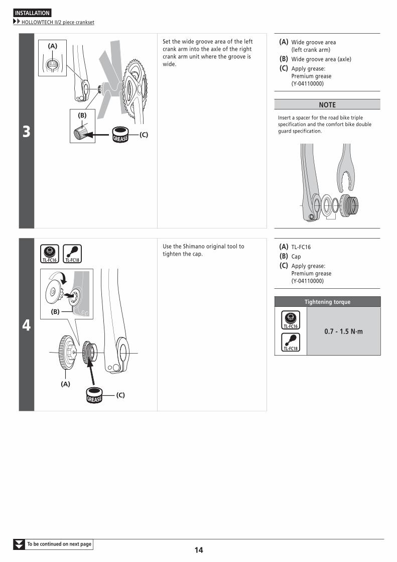
3 (C)
(B)
(A)Set the wide groove area of the left crank arm into the axle of the right crank arm unit where the groove is wide.
(A) Wide groove area (left crank arm)
(B) Wide groove area (axle)
(C) Apply grease: Premium grease (Y-04110000)
NOTE
Insert a spacer for the road bike triple specification and the comfort bike double guard specification.
4
(A)
(B)
(C)
Use the Shimano original tool to tighten the cap.
(A) TL-FC16
(B) Cap
(C) Apply grease: Premium grease (Y-04110000)
Tightening torque
0.7 - 1.5 N·m

INSTALLATION
HOLLOWTECH II/2 piece crankset
15
5
(A)
(B)
(z)
(C)
Push in the stopper plate and check that the plate pin is securely in place, and then tighten the bolt of the left crank arm.
(z) The illustration is of the left crank arm (cross-section)
(A) Plate pin
(B) Stopper plate
(C) Left crank arm
Tightening torque
12 - 14 N·m
NOTE
• For MTB/Trekking Spacers used vary according to the width of the bottom bracket shell. For details, refer to “Spacer installation method”.
• Set the stopper plate in the correct direction as shown in illustration.

INSTALLATION
OCTALINK type
16
� OCTALINK type
Installation of the bottom bracket
(A) (B) (C)
Apply grease to the main body, and install using the Shimano original tool.
First install the main body, then the adapter.
(A) Adapter
(B) Body
(C) Apply grease: Premium grease (Y-04110000)
Tightening torque
50 - 70 N·m
NOTE
If the adapter is made of aluminum or steel Apply grease to the adapter.
If the adapter is made of plasticDo not apply grease to the adapter.
Installation of the front chainwheel
(A)
Use a hexagon wrench to install the front chainwheel.
(A) 8mm hexagon wrench/ 10mm hexagon wrench
Tightening torque
35 - 50 N·m

INSTALLATION
SQUARE type
17
� SQUARE type
Installation of the bottom bracket
(A) (B)
(C)
Install using the Shimano original tool.
First install the main body, then the adapter.
(A) Adapter
(B) Body
(C) Front chainwheel
Tightening torque
50 - 70 N·m
NOTE
If the main body and adapter are made of aluminum or steel Apply grease to the main body and adapter.
Apply grease: Premium grease (Y-04110000)
If the main body and adapter are made of plastic Do not apply grease to the main body or adapter.
INSTALLATION
SQUARE type
18
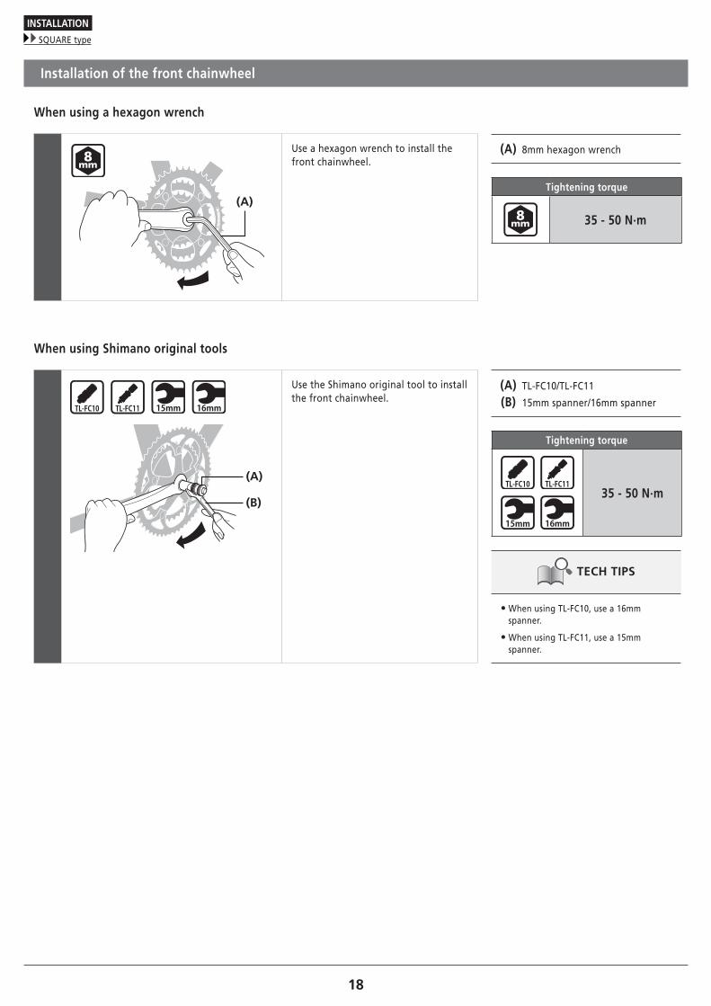
Installation of the front chainwheel
When using a hexagon wrench
(A)
Use a hexagon wrench to install the front chainwheel.
(A) 8mm hexagon wrench
Tightening torque
35 - 50 N·m
When using Shimano original tools
(A)
(B)
Use the Shimano original tool to install the front chainwheel.
(A) TL-FC10/TL-FC11
(B) 15mm spanner/16mm spanner
Tightening torque
35 - 50 N·m
TECH TIPS
• When using TL-FC10, use a 16mm spanner.
• When using TL-FC11, use a 15mm spanner.

PRESS-FIT BB
PRESS-FIT BB
Adapter
20
PRESS-FIT BB
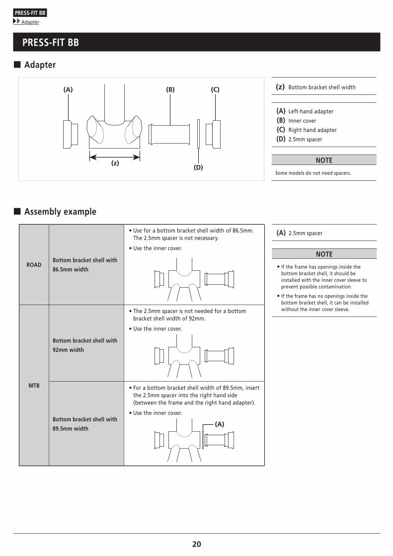
� Adapter
(A) (C)(B)
(D)(z)
(z) Bottom bracket shell width
(A) Left-hand adapter
(B) Inner cover
(C) Right hand adapter
(D) 2.5mm spacer
NOTE
Some models do not need spacers.
� Assembly example
ROADBottom bracket shell with
86.5mm width
• Use for a bottom bracket shell width of 86.5mm. The 2.5mm spacer is not necessary.
• Use the inner cover.
(A) 2.5mm spacer
NOTE
• If the frame has openings inside the bottom bracket shell, it should be installed with the inner cover sleeve to prevent possible contamination.
• If the frame has no openings inside the bottom bracket shell, it can be installed without the inner cover sleeve.
MTB
Bottom bracket shell with
92mm width
• The 2.5mm spacer is not needed for a bottom bracket shell width of 92mm.
• Use the inner cover.
Bottom bracket shell with
89.5mm width
• For a bottom bracket shell width of 89.5mm, insert the 2.5mm spacer into the right hand side (between the frame and the right hand adapter).
• Use the inner cover.
(A)

PRESS-FIT BB
Installation
21
� Installation
1
Insert the bottom bracket into the bottom bracket shell.
2
(A)Insert the Shimano original tool into the bottom bracket.
(A) TL-BB12
3
(B)(A)
Press fit the bottom bracket by tightening with a spanner while making sure that the contact surface of the bottom bracket stays parallel to the contact surface of the bottom bracket shell.
(A) 17mm spanner
(B) 8mm hexagon wrench
4
Check to confirm that there is no gap between the bottom bracket and the bottom bracket shell.

PRESS-FIT BB
Removal
22
� Removal
1 (A)
Insert the Shimano original tool into the bottom bracket.
(A) TL-BB13
NOTE
Do not reuse the adapters as they can be damaged during removal.
2
As shown in the illustration, hold down the flap with your fingers and push it in from the opposite side.(When pushed in, the flap opens.)
TECH TIPS
While holding down the end of the removal tool, push the tool in from the other side until it locks in place.
3(A)
Tap the Shimano original tool with a plastic mallet until the end of the bottom bracket is ejected.
(A) Plastic mallet
4
(A)
Tap the opposite end of the bottom bracket in the same way and remove it.
(A) Plastic mallet

MAINTENANCE

MAINTENANCE
Replacing chainrings
24
MAINTENANCE
� Replacing chainrings
NOTE
For models that are not described here, refer to the section "INSTALLATION (CHAINRINGS)" in General Operations.
Single gear type
The marked side of the chainring is the front and it should be set so that the Δ mark is positioned under the crank arm.
(A) Mark
(B) Crank arm
(C) Δ mark
Tightening torque
12 - 14 N·m
(A)
(B)(C)

MAINTENANCE
Replacing chainrings
25
Double gear type
1
With the marked side of the largest chainring facing outward, set the largest chainring so that the chain drop prevention pin is positioned under the crank arm.
(A) Mark
(B) Crank arm
(C) Chain drop prevention pin
Tightening torque
12 - 14 N·m
(A)
(B)
(C)
2
With the marked side of the smallest chainring facing inward, set the smallest chainring so that the convex section is positioned under the crank arm.
(A) Crank arm
(B) Convex section
Tightening torque
16 - 17 N·m
(A)
(B)
MAINTENANCE
Replacing chainrings
26
Triple gear type
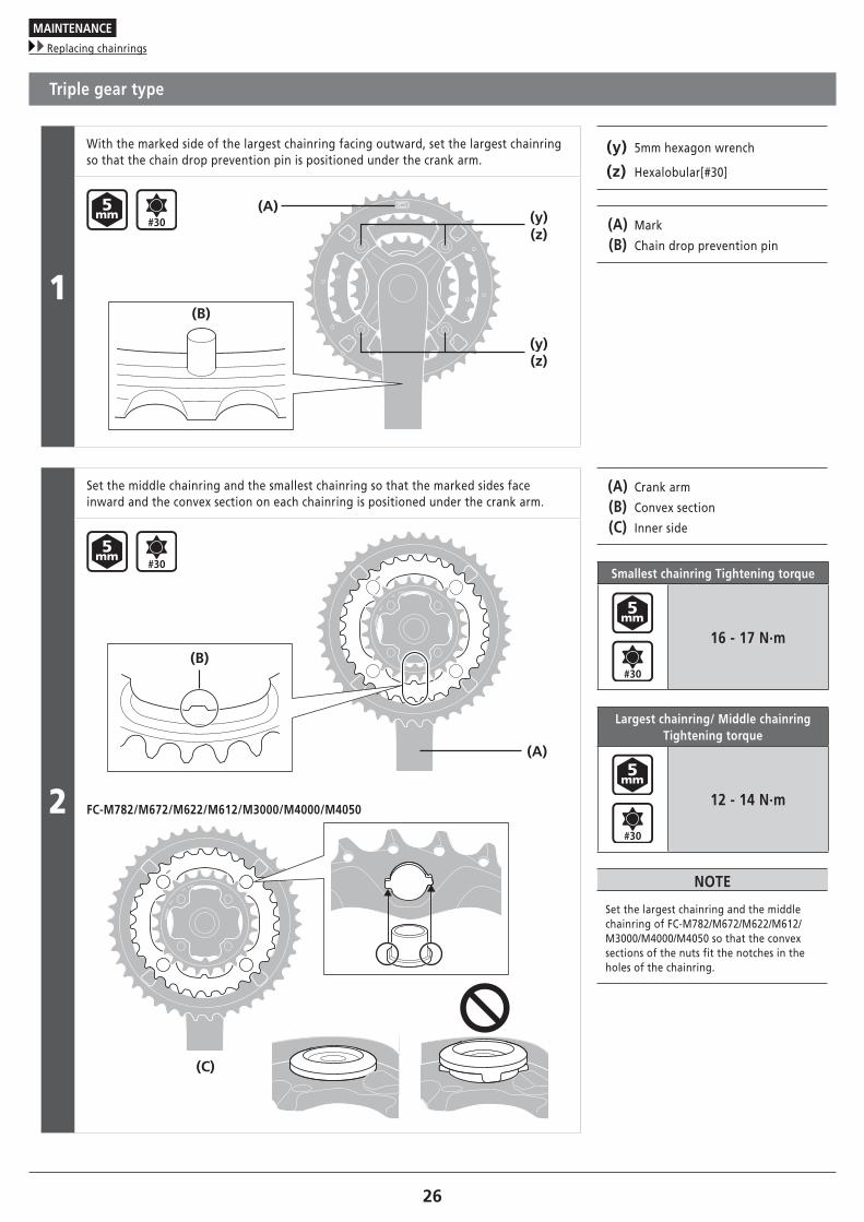
1
With the marked side of the largest chainring facing outward, set the largest chainring so that the chain drop prevention pin is positioned under the crank arm.
(y) 5mm hexagon wrench
(z) Hexalobular[#30]
(A) Mark
(B) Chain drop prevention pin
(B)
(A)(y)(z)
(y)(z)
2
Set the middle chainring and the smallest chainring so that the marked sides face inward and the convex section on each chainring is positioned under the crank arm.
(A) Crank arm
(B) Convex section
(C) Inner side
Smallest chainring Tightening torque
16 - 17 N·m
Largest chainring/ Middle chainring Tightening torque
12 - 14 N·m
NOTE
Set the largest chainring and the middle chainring of FC-M782/M672/M622/M612/M3000/M4000/M4050 so that the convex sections of the nuts fit the notches in the holes of the chainring.
(A)
(B)
FC-M782/M672/M622/M612/M3000/M4000/M4050
(C)

MAINTENANCE
Replacing chainrings
27
Chain guide type
(B)
(A)
(y)(z)
(y)(z)
(x)
(x) Convex section
(y) 5mm hexagon wrench
(z) Hexalobular[#30]
(A) Top guard
(B) Crank arm
NOTE
The side with indentations around the holes is the front of the top guard and it should be set so that the inside convex section of the chainring is at the crank arm position.
No chain guide type
(A)
(B)
(C)
(A) Δ mark
(B) Mark
(C) Convex section
TECH TIPS
• For 45T/42T The marked side of the chainring is the front and it should be set with the Δ mark lined up with position of the crank arm.
• For 39T The marked side of the chainring is the reverse and it should be set so that the inside convex section of the chainring is at the crank arm position.

MAINTENANCE
Replacing chainrings
28
FC-M8000 Single gear type
Set the chainring so that the marked side faces the front, and set the crank arm as shown in the illustration.
(A) Mark
(B) Crank arm
Tightening torque
12 - 14 N·m(A)
(B)
MAINTENANCE
Replacing chainrings
29
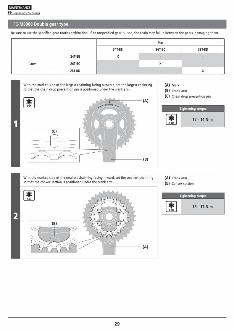
FC-M8000 Double gear type
Be sure to use the specified gear tooth combination. If an unspecified gear is used, the chain may fall in between the gears, damaging them.
Top
34T-BB 36T-BC 38T-BD
Low
24T-BB X - -
26T-BC - X -
28T-BD - - X
1
With the marked side of the largest chainring facing outward, set the largest chainring so that the chain drop prevention pin is positioned under the crank arm.
(A) Mark
(B) Crank arm
(C) Chain drop prevention pin
Tightening torque
12 - 14 N·m
(A)
(B)
(C)
2
With the marked side of the smallest chainring facing inward, set the smallest chainring so that the convex section is positioned under the crank arm.
(A) Crank arm
(B) Convex section
Tightening torque
16 - 17 N·m
(A)
(B)

MAINTENANCE
Replacing chainrings
30
About FC-M8000-2/FC-M8000-B2 maintenance gears
Part Model Chain drop prevention pin
ChainringFC-M8000-2
Use with chain drop prevention pin cover.
FC-M8000-B2
Remove chain drop prevention pin cover.
(A)
(B)
(A) Chain drop prevention pin
(B) Chain drop prevention pin cover
NOTE
• If combined with a standard specification front chainwheel with the chain drop prevention pin cover off, when the chain falls on the outside of the front chainwheel, the chain may get caught between the crank and the top gear.
• If combined with a B specification front chainwheel with the chain drop prevention pin cover on, the cover will interfere with the crank, and it will not be possible to assemble the gear correctly. It may cause the chain to fall, etc.
• Removed chain drop prevention pin covers cannot be reused.
MAINTENANCE
Replacing chainrings
31
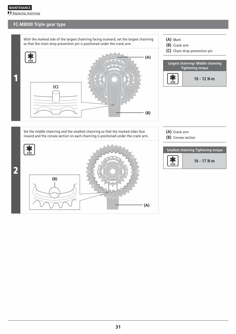
FC-M8000 Triple gear type
1
With the marked side of the largest chainring facing outward, set the largest chainring so that the chain drop prevention pin is positioned under the crank arm.
(A) Mark
(B) Crank arm
(C) Chain drop prevention pin
Largest chainring/ Middle chainring Tightening torque
10 - 12 N·m
(A)
(B)
(C)
2
Set the middle chainring and the smallest chainring so that the marked sides face inward and the convex section on each chainring is positioned under the crank arm.
(A) Crank arm
(B) Convex section
Smallest chainring Tightening torque
16 - 17 N·m
(A)
(B)

Please note: specifications are subject to change for improvement without notice. (English) © Jul. 2016 by Shimano Inc. HTR
Related Documents