International Research Journal of Engineering and Technology (IRJET) e-ISSN: 2395 -0056 Volume: 04 Issue: 06 | June -2017 www.irjet.net p-ISSN: 2395-0072 © 2017, IRJET | Impact Factor value: 5.181 | ISO 9001:2008 Certified Journal | Page 2294 FINITE ELEMENT ANALYSIS OF ROLLER BURNISHING PROCESS Shailesh Dadmal 1 , Prof. Vijay Kurkute 2 1 PG Student, Mechanical Department, Bharati Vidyapeeth University, College of Engineering, Pune, Maharashtra, India, 2 Associate Professor, Mechanical Department, Bharati Vidyapeeth University, College of Engineering, Pune, Maharashtra, India ---------------------------------------------------------------------***--------------------------------------------------------------------- Abstract – In today’s time, the manufacturing of machines and other components with highly furnished surfaces are becoming more and more important. Drastic attention is being given on the equality of the surface. Surface finishing is the mandatory characteristic of any produced machine. The operation, which can easily improve surface roughness of machinery parts, is called as Burnishing Operation and it is getting evolved day by day. It basically involves plastic deformation of the material. It is a cold rolling process, without any removal of metal from the work piece. An assembly of roller or ball is used as the work tool on the work piece with sufficient pressure applied on the work piece, and hence the process get computes. Peaks get changed into valleys and at last a highly polished mirror like surface is obtained. In case of sliding surfaces, it enhances the life of the material. This paper explains the finite element analysis of roller burnishing process. Surface finishing has a prolonged effect on every material. It is applied to implement a successful hard roller burnishing process. The consequence of burnishing parameters along with surface integrity needs to be evaluated before actual functioning. In this paper we have presented a process of developing a 2D model using transient structural analysis of roller burnishing process. While doing finite element analysis only force parameter will be considered. Key Words: Surface Roughness, Surface Hardness, Finite Element Analysis (FEA), Roller Burnishing Process 1. INTRODUCTION There is a large significance of alternate energy sources like solar and wind. In high time world of globalization and urbanization, the performance of the machine is highly dependent on dimensional accuracy, geometrical tolerance and surface finish of the component. In order to obtain good accuracy with proper matching of parts without any tolerance requires a very good surface finishing. The surface finishing procedure plays a very important role in manufacturing industries for each kind of machinery part. Lots of emphasis is given on the quality of surface for getting desired physical and mechanical properties. Over the span of last few years a lot of research is being done on metal surface finishing to increase the surface properties of the machinery parts. The metal finishing process are basically divided into two main divisions as follows: 1. Based on Abrasives, like cutting action. For example, Honing, lapping, buffing, polishing, grinding. 2. On plastic deformation of surface. For example, burnishing, short peening, barrel rolling, short blasting etc. Around the world there are number of several finishing process that are used to obtain surface with required quality properties. Whereas, burnishing is used widely for processing external and internal surfaces of machinery parts. In this procedure two types of tools can be used (1. One or more balls made of hardened steel, 2. one or more rollers made of harden steel). In case of balls sliding friction takes place. Whereas in second case rolling friction takes place. 1.1 Burnishing Operation In the burnishing operation, the surface properties of the material changes as a result of plastic deformation process, which produces a high surface finish by the rotation of tool over the surface. The tool may further consist of a ball or a roller as per requirement. We know that surface finishing is a process which doesn’t involve removal of material. It basically helps in minimizing the distance of peaks from its mean and ultimately decreases the roughness of surface. Fig 1: Basic Operation of Burnishing 1.2 Working Principle of Burnishing Burnishing process is a highly flexible operation that decreases surface irregularities and improves the dimension of parts without any further requirement of tooling on simply turning the workpiece into convention lathe. It reduces the machinery cost, human effort and time required for remounting of components. The tool used can be a single ruler or multiple roller which are held in tool post. This tool is mounted on the tool post of the lathe. When

Welcome message from author
This document is posted to help you gain knowledge. Please leave a comment to let me know what you think about it! Share it to your friends and learn new things together.
Transcript

International Research Journal of Engineering and Technology (IRJET) e-ISSN: 2395 -0056
Volume: 04 Issue: 06 | June -2017 www.irjet.net p-ISSN: 2395-0072
© 2017, IRJET | Impact Factor value: 5.181 | ISO 9001:2008 Certified Journal | Page 2294
FINITE ELEMENT ANALYSIS OF ROLLER BURNISHING PROCESS
Shailesh Dadmal1, Prof. Vijay Kurkute2
1PG Student, Mechanical Department, Bharati Vidyapeeth University, College of Engineering, Pune, Maharashtra, India,
2Associate Professor, Mechanical Department, Bharati Vidyapeeth University, College of Engineering, Pune, Maharashtra, India
---------------------------------------------------------------------***---------------------------------------------------------------------
Abstract – In today’s time, the manufacturing of machines and other components with highly furnished surfaces are becoming more and more important. Drastic attention is being given on the equality of the surface. Surface finishing is the mandatory characteristic of any produced machine. The operation, which can easily improve surface roughness of machinery parts, is called as Burnishing Operation and it is getting evolved day by day. It basically involves plastic deformation of the material. It is a cold rolling process, without any removal of metal from the work piece. An assembly of roller or ball is used as the work tool on the work piece with sufficient pressure applied on the work piece, and hence the process get computes. Peaks get changed into valleys and at last a highly polished mirror like surface is obtained. In case of sliding surfaces, it enhances the life of the material. This paper explains the finite element analysis of roller burnishing process. Surface finishing has a prolonged effect on every material. It is applied to implement a successful hard roller burnishing process. The consequence of burnishing parameters along with surface integrity needs to be evaluated before actual functioning. In this paper we have presented a process of developing a 2D model using transient structural analysis of roller burnishing process. While doing finite element analysis only force parameter will be considered.
Key Words: Surface Roughness, Surface Hardness, Finite Element Analysis (FEA), Roller Burnishing Process
1. INTRODUCTION There is a large significance of alternate energy sources like solar and wind. In high time world of globalization and urbanization, the performance of the machine is highly dependent on dimensional accuracy, geometrical tolerance and surface finish of the component. In order to obtain good accuracy with proper matching of parts without any tolerance requires a very good surface finishing. The surface finishing procedure plays a very important role in manufacturing industries for each kind of machinery part. Lots of emphasis is given on the quality of surface for getting desired physical and mechanical properties. Over the span of last few years a lot of research is being done on metal surface finishing to increase the surface properties of the machinery parts.
The metal finishing process are basically divided into two main divisions as follows:
1. Based on Abrasives, like cutting action. For example, Honing, lapping, buffing, polishing, grinding. 2. On plastic deformation of surface. For example, burnishing, short peening, barrel rolling, short blasting etc. Around the world there are number of several finishing process that are used to obtain surface with required quality properties. Whereas, burnishing is used widely for processing external and internal surfaces of machinery parts. In this procedure two types of tools can be used (1. One or more balls made of hardened steel, 2. one or more rollers made of harden steel). In case of balls sliding friction takes place. Whereas in second case rolling friction takes place.
1.1 Burnishing Operation
In the burnishing operation, the surface properties of the material changes as a result of plastic deformation process, which produces a high surface finish by the rotation of tool over the surface. The tool may further consist of a ball or a roller as per requirement. We know that surface finishing is a process which doesn’t involve removal of material. It basically helps in minimizing the distance of peaks from its mean and ultimately decreases the roughness of surface.
Fig 1: Basic Operation of Burnishing
1.2 Working Principle of Burnishing
Burnishing process is a highly flexible operation that decreases surface irregularities and improves the dimension of parts without any further requirement of tooling on simply turning the workpiece into convention lathe.
It reduces the machinery cost, human effort and time required for remounting of components. The tool used can be a single ruler or multiple roller which are held in tool post. This tool is mounted on the tool post of the lathe. When

International Research Journal of Engineering and Technology (IRJET) e-ISSN: 2395 -0056
Volume: 04 Issue: 06 | June -2017 www.irjet.net p-ISSN: 2395-0072
© 2017, IRJET | Impact Factor value: 5.181 | ISO 9001:2008 Certified Journal | Page 2295
the tool gets pressed against the rotating workpiece, the frictional force comes in picture between the roller and the workpiece. The direction of the rotation of the workpiece is always opposite to that of the tool. Burnishing process is sometimes also known as cold working process.
1.3 Process Parameters of Burnishing Operation
The burnishing operation can be control by the various process parameters which are known as burnishing process parameters. All these different process parameters need to control and optimize to get the best results. The various process parameters are as follows:
1. Burnishing speed 2. Feed Rate 3. Burnishing Force 4. Number of Passes 1.3.1 Burnishing Speed The burnishing speed at which the work piece is rotated during burnishing operation. The burnishing speed is given to either work piece or burnishing tool. In Flat surface burnishing operation, the burnishing tool rotated and work piece remains stationary. Burnishing speed is mainly given in Revolution / Minute or mm / Minute. Strength and dimension of work piece decided the speed of burnishing operation. 1.3.2 Feed Rate Feed rate is the linear velocity with which tool is fed related to work piece. The feed rate is generally measured in terms of mm per revolutions. The amount of surface finish required defines the feed rate. For high surface finish, the feed rate should be minimum. So the feed rate should be optimizing for the better surface finish. 1.3.3 Burnishing Force
The burnishing tool is pressed against work piece during burnishing operation. The force exert by burnishing tool on the work piece is known as the burnishing force. The burnishing force acts perpendicular on the work piece surface. In burnishing process, the burnishing force is very important and most critical parameter among all other parameter because surface roughness after burnishing operation mainly depends on force with which the burnishing tool is pressed against workpiece. The force required during burnishing operation should be high enough to modify surface asperities and to flow material from peaks into valleys. The burnishing force is mainly depending on yield strength of material.
1.3.4 Number of tool passes Sometimes the burnishing operation is repeatedly done on work piece by using same process parameters. Due to this, it helps to enhance the surface roughness. In some applications, the number of tool passes may go up to several number of times depending upon the surface roughness required and strength of the work piece.
1.4 Surface Roughness
Surface of machinery components provides a link between manufacturing and their various function in used. It has been observed that 80% of machine failures are because of wear of contact surfaces in meeting parts. The life of machine parts can be increased by avoiding the wear of components. Hence it is highly recommended to make the parts highly smooth with no roughness on their boundaries or edges. It is basically the deviation in the direction of normal vector of real surface from the ideal form. The rough surfaces usually have high coefficient of friction as compared to the smooth surface and they normally wear out rapidly as compared to smooth surface.
Fig 2: Surface Profile Advantages of Good surface finish are: 1. Excellent surface finish increases the wear resistance of the workpiece in contact. 2. It reduces the friction between two workpiece. 3. Good surface finishes result in high cosmetic effect and also increases the load carrying capacity. It also decreases the corrosion and fatigue life of components.
2. LITERATURE SURVEY
M.H. El-Axir [1] studied the influence of different burnishing conditions on both surface micro hardness and roughness: namely, burnishing speed, force, feed, and number of passes. Initially roughness of about Ra 4.5 µm can be finished to a roughness of 0.5 µm. A good correlation between the experimental and predicted results derived from the model was exhibited.
International Research Journal of Engineering and Technology (IRJET) e-ISSN: 2395 -0056
Volume: 04 Issue: 06 | June -2017 www.irjet.net p-ISSN: 2395-0072
© 2017, IRJET | Impact Factor value: 5.181 | ISO 9001:2008 Certified Journal | Page 2296
Partchapol Sartkulvanich [2] et all in this study, 2D and 3D FEM models were established. Simulation results were evaluated and compared to the experimental data. Both FEM and experiments show the burnshing pressure is the most influence, where high burnishing pressure less roughness and more compresssive residual stress at the surface.
J.N. Malleswara Rao [3] et all in the present work, experimental work is carried out to reduce the surface roughness of a specially fabricated aluminum work piece, by roller burnishing process on lathe. FEA model is developed to compare experimental results. The results are found to coincide with the values got from the experimental readings, and the variations are less than 10 %.
P.Saritha [4] states that Roller burnishing process is used to get a good surface finish of materials such as aluminum and mild steel. Their results obtained for contact stresses in a roller burnishing process are found on using the different theories and numerical methods. Different contact Models of the burnishing process are used in the present FEA analysis. The Contact Analysis Prove to about 10 to 15% variation in results.
B. Pattabhi Reddy [5] et all investigated surface characteristics like Surface Hardness and Surface Roughness of roller burnishing components are performed by considering different parameters like Speed, Feed, Force and Passes. Analysis is performed by ANSYS software. The Results from the ANSYS are compared with Results obtained from different theories and Contact Models of FEA analysis.
Prof. Ghodke A. P [6] et all reviwed effect of burnishing process on behaviour of engineering materials. Two important paramters to improve ductility of materials are burnishing force and burnishing tool passes. As compared to other surface finishing processes burnishing can give better surface quality and dimensional accuracy.
3. WORKPIECE & EQUIPMENTS
3.1 Workpiece Material
Burnishing Operations make use of tuned aluminum workpiece. It is used because it is very much ductile, corrosive resistant, good conductor and very much available in the form of round bars. This workpiece is specially fabricated. The pre-determined chemical composition of aluminum specimen (WT%) is as follows:
Table 1: Chemical Composition of the Al 6061
Fig 3: Workpiece
3.2 Major Equipment
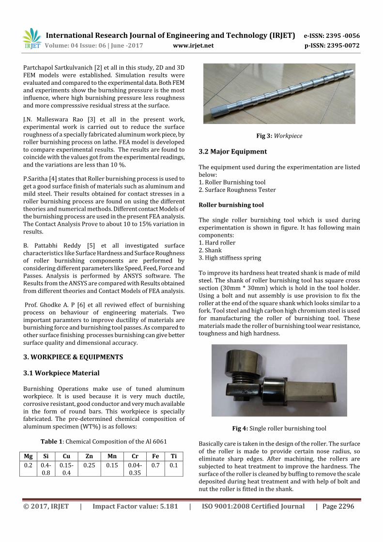
The equipment used during the experimentation are listed below: 1. Roller Burnishing tool 2. Surface Roughness Tester Roller burnishing tool The single roller burnishing tool which is used during experimentation is shown in figure. It has following main components: 1. Hard roller 2. Shank 3. High stiffness spring To improve its hardness heat treated shank is made of mild steel. The shank of roller burnishing tool has square cross section (30mm * 30mm) which is hold in the tool holder. Using a bolt and nut assembly is use provision to fix the roller at the end of the square shank which looks similar to a fork. Tool steel and high carbon high chromium steel is used for manufacturing the roller of burnishing tool. These materials made the roller of burnishing tool wear resistance, toughness and high hardness.
Fig 4: Single roller burnishing tool
Basically care is taken in the design of the roller. The surface of the roller is made to provide certain nose radius, so eliminate sharp edges. After machining, the rollers are subjected to heat treatment to improve the hardness. The surface of the roller is cleaned by buffing to remove the scale deposited during heat treatment and with help of bolt and nut the roller is fitted in the shank.
Mg Si Cu Zn Mn Cr Fe Ti
0.2 0.4-0.8
0.15-0.4
0.25 0.15 0.04-0.35
0.7 0.1

International Research Journal of Engineering and Technology (IRJET) e-ISSN: 2395 -0056
Volume: 04 Issue: 06 | June -2017 www.irjet.net p-ISSN: 2395-0072
© 2017, IRJET | Impact Factor value: 5.181 | ISO 9001:2008 Certified Journal | Page 2297
Surface roughness tester As a stylus instrument, we used surface roughness tester (MITUTOYO Model -SJ211). The working principle of surface roughness tester is based on moving the probe of tester on surface whose roughness is to be measure. Generally, the probe is made up of hard material to resist the wear as it is continuously in contact with surface whose roughness is to measure.
Fig 5: Surface Roughness Tester
4. EXPERIMENTAL SETUP
Burnishing process is a super finishing process as burnishing is super finishing operation which does not consist of removal of material from work piece. These components cannot be suitable to be burnished directly due to inherent flaws like scaling, out of roundness, irregular diameter etc.
Fig 6: Experimental Setup
The wok piece should be undergoing through different machining process, to make material free from surface imperfections. Firstly, facing and turning operations are carried out and after that work piece is burnished by using single roller burnishing tool. Experimentation is conducted on CNC lathe and for measurement of force we have used dynamometer. The process of burnishing is well explained below: Burnishing Operation: The main advantage of burnishing operation is that it saves good amount of production time because there is no need to remove the work piece from lathe machine and re-clamped
on some other machine. The roller burnishing tool is clamped on the tool post of lathe machine which is fed against work piece during burnishing operation.
Fig 7: Burnishing Operation
5. FINITE ELEMENT ANALYSIS
FEA allow us to evaluate a detailed and highly complex structurer on a computer. While planning the structure. It is also being known to increase the efficiency of structure that were somewhat over designed for the time when FEA was not available, the development of structures was highly dependent on hand calculation. HC might lead to small errors and this may result in significant change in design which will increase the risk. With the help of FEA the weight of a design can be decreased and there can be reduction in number of prototype built. ANSYS is a general purpose software it can be used for almost every type of finite element analysis. In every industry like electronics, automobiles, aerospace etc. ANSYS program can be in two different modes i.e. interactive mode or batch mode. The ANSYS major system is also organized into logical grouping of related topics. The major ones are main components, utility and referred. General steps for solving any engineering problems using FEA: 1. Pre-Processing 2. Processing / Solution 3. Post-Processing In ANSYS Workbench there are five main steps for the
transient structural analysis are as follows:
1. Engineering data 2. Geometry 3. Model 4. Set up 5. Solution Engineering Data In engineering data, we select the materials required for the analysis which are used in study. In engineering data sources, there are various data sources like general materials, general non-linear materials, explicit materials, hyper elastic materials, magnetic B-H curve, thermal materials, fluid materials, composite material etc. and under

International Research Journal of Engineering and Technology (IRJET) e-ISSN: 2395 -0056
Volume: 04 Issue: 06 | June -2017 www.irjet.net p-ISSN: 2395-0072
© 2017, IRJET | Impact Factor value: 5.181 | ISO 9001:2008 Certified Journal | Page 2298
these data sources their different material options to choose the required material for analysis. In this study, aluminum is used as work piece material hence from engineering data source aluminum alloy which comes under general materials. As we select aluminum material the workbench software will takes its physical material properties automatically.
Geometry In this we can make the geometry in software itself or can import the geometry/model from any modelling software like CATIA, CREO, Solid works etc. For simple geometries we can used this software but for completed real life problem models are difficult to develop hence for this we have to build the model in any modelling software and can import the model in the ANSYS. In this study, 2d FEM model is developed in ANSYS itself as it is a simple model. For FEM model we have assumed height of surface roughness peak as 3.2 µm and included angle of 80°. For modelling we have select the line option from sketching and drawn the line model as per assumptions, from line model surface is developed using surface from sketches which is in concept option. Now this surface created nine times towards right side linearly using pattern option as shown in fig 8.
Fig 8: 2D FEM Model / geometry
Model After geometry next step is model. In this, we can give the various parameters to the geometry like thickness also assign the material if we choose more than two materials in engineering data otherwise it will take structural steel since it is a default material of ANSYS Workbench. After this we can give the connections for the contacts between models and finally we do the meshing to the geometry by using mesh option. Meshing is a discretization of an object into nodes and elements. For good meshing, mesh refinement there are various options like method, sizing, contact meshing, refinement, face meshing, match control etc. we use these options depending on the geometry shape and size. While doing meshing we have to consider the parameters like solution time, computer system on which we are doing the
analysis i.e., depending on the time constraint, computer system etc. we do the meshing. In this study, aluminum material is assigned for surface body (geometry) from material assignment option. Meshing is done just by clicking on generate mesh option and it automatically generates the mesh to the surface body as shown in fig 9.
Fig 9: Model after Meshing
Setup In this we give the boundary conditions depending on the problem or application. There are various boundary conditions like fixed support, force, pressure, displacement, remote displacement, velocity and many others required for analysis. In this study, fixed support and force are inserted for the analysis. Fixed support is given at the bottom edge and side edges of the model and Forces are given on all nine peaks in vertically downward direction i.e., along y-axis as shown in fig 10. Set of forces taken for analyses are 20N, 40N, 60N, 80N, 100N. Fig 10 shows the boundary conditions for 80N force.
Fig 10: model after boundary conditions
Solution Above all steps i.e. engineering data, geometry, model, setup comes under pre-processing. In solution or processing we have just to click on the solve icon. Software internally carried out the matrix formation, multiplication, inversion and solution for unknown e.g. displacement and then finds the stress & strain for analysis. In solution we insert the required results.
International Research Journal of Engineering and Technology (IRJET) e-ISSN: 2395 -0056
Volume: 04 Issue: 06 | June -2017 www.irjet.net p-ISSN: 2395-0072
© 2017, IRJET | Impact Factor value: 5.181 | ISO 9001:2008 Certified Journal | Page 2299
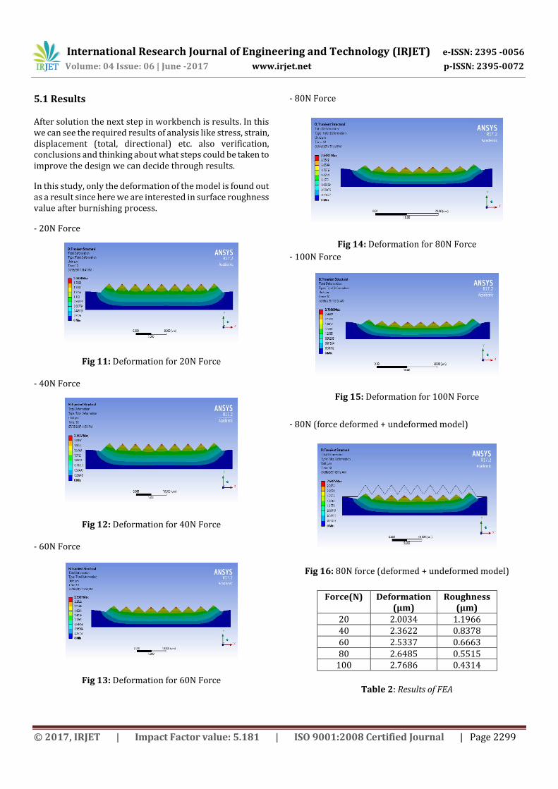
5.1 Results
After solution the next step in workbench is results. In this we can see the required results of analysis like stress, strain, displacement (total, directional) etc. also verification, conclusions and thinking about what steps could be taken to improve the design we can decide through results.
In this study, only the deformation of the model is found out as a result since here we are interested in surface roughness value after burnishing process.
- 20N Force
Fig 11: Deformation for 20N Force
- 40N Force
Fig 12: Deformation for 40N Force
- 60N Force
Fig 13: Deformation for 60N Force
- 80N Force
Fig 14: Deformation for 80N Force - 100N Force
Fig 15: Deformation for 100N Force
- 80N (force deformed + undeformed model)
Fig 16: 80N force (deformed + undeformed model)
Force(N) Deformation (µm)
Roughness (µm)
20 2.0034 1.1966 40 2.3622 0.8378 60 2.5337 0.6663 80 2.6485 0.5515
100 2.7686 0.4314
Table 2: Results of FEA
International Research Journal of Engineering and Technology (IRJET) e-ISSN: 2395 -0056
Volume: 04 Issue: 06 | June -2017 www.irjet.net p-ISSN: 2395-0072
© 2017, IRJET | Impact Factor value: 5.181 | ISO 9001:2008 Certified Journal | Page 2300
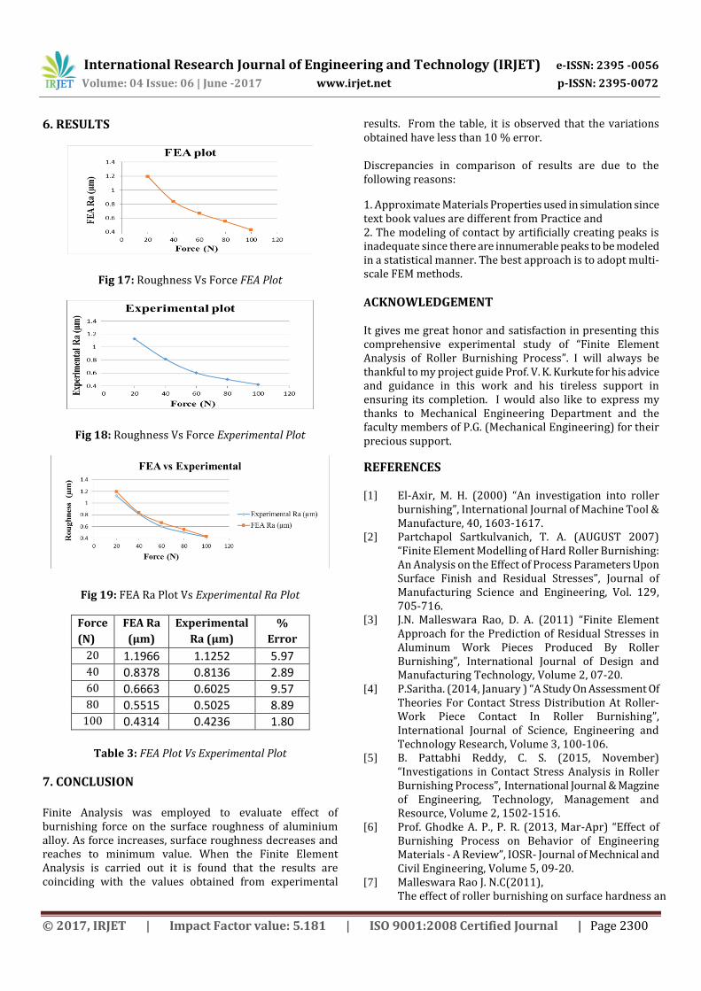
6. RESULTS
Fig 17: Roughness Vs Force FEA Plot
Fig 18: Roughness Vs Force Experimental Plot
Fig 19: FEA Ra Plot Vs Experimental Ra Plot
Force
(N)
FEA Ra
(µm)
Experimental
Ra (µm)
%
Error
20 1.1966 1.1252 5.97 40 0.8378 0.8136 2.89 60 0.6663 0.6025 9.57 80 0.5515 0.5025 8.89
100 0.4314 0.4236 1.80
Table 3: FEA Plot Vs Experimental Plot
7. CONCLUSION
Finite Analysis was employed to evaluate effect of burnishing force on the surface roughness of aluminium alloy. As force increases, surface roughness decreases and reaches to minimum value. When the Finite Element Analysis is carried out it is found that the results are coinciding with the values obtained from experimental
results. From the table, it is observed that the variations obtained have less than 10 % error.
Discrepancies in comparison of results are due to the following reasons:
1. Approximate Materials Properties used in simulation since text book values are different from Practice and 2. The modeling of contact by artificially creating peaks is inadequate since there are innumerable peaks to be modeled in a statistical manner. The best approach is to adopt multi-scale FEM methods.
ACKNOWLEDGEMENT It gives me great honor and satisfaction in presenting this comprehensive experimental study of “Finite Element Analysis of Roller Burnishing Process”. I will always be thankful to my project guide Prof. V. K. Kurkute for his advice and guidance in this work and his tireless support in ensuring its completion. I would also like to express my thanks to Mechanical Engineering Department and the faculty members of P.G. (Mechanical Engineering) for their precious support.
REFERENCES
[1] El-Axir, M. H. (2000) “An investigation into roller burnishing”, International Journal of Machine Tool & Manufacture, 40, 1603-1617.
[2] Partchapol Sartkulvanich, T. A. (AUGUST 2007) “Finite Element Modelling of Hard Roller Burnishing: An Analysis on the Effect of Process Parameters Upon Surface Finish and Residual Stresses”, Journal of Manufacturing Science and Engineering, Vol. 129, 705-716.
[3] J.N. Malleswara Rao, D. A. (2011) “Finite Element Approach for the Prediction of Residual Stresses in Aluminum Work Pieces Produced By Roller Burnishing”, International Journal of Design and Manufacturing Technology, Volume 2, 07-20.
[4] P.Saritha. (2014, January ) “A Study On Assessment Of Theories For Contact Stress Distribution At Roller- Work Piece Contact In Roller Burnishing”, International Journal of Science, Engineering and Technology Research, Volume 3, 100-106.
[5] B. Pattabhi Reddy, C. S. (2015, November) “Investigations in Contact Stress Analysis in Roller Burnishing Process”, International Journal & Magzine of Engineering, Technology, Management and Resource, Volume 2, 1502-1516.
[6] Prof. Ghodke A. P., P. R. (2013, Mar-Apr) “Effect of Burnishing Process on Behavior of Engineering Materials - A Review”, IOSR- Journal of Mechnical and Civil Engineering, Volume 5, 09-20.
[7] Malleswara Rao J. N.C(2011), The effect of roller burnishing on surface hardness an

International Research Journal of Engineering and Technology (IRJET) e-ISSN: 2395 -0056
Volume: 04 Issue: 06 | June -2017 www.irjet.net p-ISSN: 2395-0072
© 2017, IRJET | Impact Factor value: 5.181 | ISO 9001:2008 Certified Journal | Page 2301
d surface roughness on mild steel specimens. International Journal Of Applied Engineering Research Dindigul, Volume 4, 777-785.
[8] R. G. Solanki, K. A. (2016, May- Jun). Parametric Optimization of Roller Burnishing Process for Surface Roughness. IOSR Journal of Mechanical and Civil Engineering , Volume 13, 21-26 .
[9] Nikhil Shinde, V. K. Kurkute (2016, November). Optimization Of Single Roller Burnishing Operation For Surface Roughness of Aluminium Alloy Using Artificial Neural Network. International Journal of Mechanical Engineering, 1289-1293.
[10] Ashish Deshmukh, P. (2015, July ). Analyasis and Optimization of Roller Burnishing Process on Cylindrical Surfacemicro Hardness of Aluminium Alloy . International Journal of Innovative Research in Science, Engineering and Technology, Vol. 4, 6044-6055.
BIOGRAPHIES
I, Shailesh Dadmal, am a final year M.Tech. student of Mechanical Dept. in Bharati Vidyapeeth University, College of Engineering, Pune.
I, Prof. Vijay Kurkute, am an Associate Professor of Mechanical Dept. in Bharati Vidyapeeth University, College of Engineering, Pune.
Related Documents