Page 1502 Investigations in Contact Stress Analysis in Roller Burnishing Process B. Pattabhi Reddy M.Tech (CAD/CAM), Department Of Mechanical Engineering, Malla Reddy College Of Engineering C. Shashikanth Assistant Professor Mechanical Engineering Department Malla Reddy College Of Engineering Abstract: In today’s production of machines and instrument components, finishing processes are becoming more and more important. Increasing attention is being paid to the quality of the surface finish obtained. Surface finish is a characteristic of any machined surface. To achieve this, the residual stresses which are developed in them during the machining processes are required to be estimated for which one has to know the elastic and plastic stress components. The machining processes, which can easily improve surface roughness of machine parts. Burnishing is a surface modification Process, which involves Plastic Deformation of material at the surface of component due to application a highly polished and hard roller under pressure. This paper describes the contact stress between two cylindrical components in a roller burnishing process. Surface finish has a positive and prolonged effect on the functioning of the machined parts. Roller burnishing is used to get a high quality surface finish on materials like aluminum and mild steel. Investigation on surface characteristics like Surface Hardness and Surface Roughness of roller burnishing components are performed by considering different parameters like Speed, Feed, Force and Passes. Statistical approach like Regression analysis is to be performed based on Surface characteristics by considering different parameters like Speed, Feed, Force and Passes for both Mild steel and Aluminum work Pieces. Analysis is performed by ansys software. The Results from the ansys are compared with Results obtained from different theories and Contact Models of FEA analysis. Keywords: Contact Stress Analysis, Surface Finishing, Burnishing Process, Roller Burnishing. Introduction: In manufacturing engineering it is imperative to improve the surface quality of the machine parts, which ensures their durability and reliability. In today’s production of machines and instrument components, finishing processes are becoming more and more important. Increasing attention is being paid to the quality of the surface finish obtained. Surface finish is important not only as an appearance it also has a positive and prolonged effect on the functioning of machine parts. Surface finish is a characteristic of any machined surface. It is sometimes called as surface texture or roughness. To achieve this, the residual stresses which are developed in them during the machining processes are required to be estimated for which one has to know the elastic and plastic stress components. The machining processes, which can easily improve surface roughness of machine parts. Surface roughness The surfaces of engineering components will provide link between manufacturing and their function in use. The main causes of machine failures (80%) are wear of contact surfaces in mating parts. wear resistance of rubbing parts can be improved by reducing the initial wear of components. In this line, it is better practice to make the sliding surfaces with a roughness equal to that of worn-in parts. The advantages of good surface finish are: Good surface finishes increase the wear resistance of two work pieces in an assembly. Good surface finishes reduce the friction between two work pieces in an assembly. Good surface finishes have cosmetic affect and make parts look good.

Welcome message from author
This document is posted to help you gain knowledge. Please leave a comment to let me know what you think about it! Share it to your friends and learn new things together.
Transcript

Page 1502
Investigations in Contact Stress Analysis in Roller
Burnishing Process B. Pattabhi Reddy
M.Tech (CAD/CAM),
Department Of Mechanical Engineering,
Malla Reddy College Of Engineering
C. Shashikanth
Assistant Professor
Mechanical Engineering Department
Malla Reddy College Of Engineering
Abstract:
In today’s production of machines and instrument
components, finishing processes are becoming more
and more important. Increasing attention is being
paid to the quality of the surface finish obtained.
Surface finish is a characteristic of any machined
surface. To achieve this, the residual stresses which
are developed in them during the machining
processes are required to be estimated for which one
has to know the elastic and plastic stress components.
The machining processes, which can easily improve
surface roughness of machine parts. Burnishing is a
surface modification Process, which involves Plastic
Deformation of material at the surface of component
due to application a highly polished and hard roller
under pressure. This paper describes the contact
stress between two cylindrical components in a roller
burnishing process. Surface finish has a positive and
prolonged effect on the functioning of the machined
parts. Roller burnishing is used to get a high quality
surface finish on materials like aluminum and mild
steel. Investigation on surface characteristics like
Surface Hardness and Surface Roughness of roller
burnishing components are performed by considering
different parameters like Speed, Feed, Force and
Passes. Statistical approach like Regression analysis
is to be performed based on Surface characteristics
by considering different parameters like Speed, Feed,
Force and Passes for both Mild steel and Aluminum
work Pieces. Analysis is performed by ansys software.
The Results from the ansys are compared with
Results obtained from different theories and Contact
Models of FEA analysis.
Keywords: Contact Stress Analysis, Surface
Finishing, Burnishing Process, Roller Burnishing.
Introduction:
In manufacturing engineering it is imperative to
improve the surface quality of the machine parts,
which ensures their durability and reliability. In
today’s production of machines and instrument
components, finishing processes are becoming more
and more important. Increasing attention is being paid
to the quality of the surface finish obtained. Surface
finish is important not only as an appearance it also
has a positive and prolonged effect on the functioning
of machine parts. Surface finish is a characteristic of
any machined surface. It is sometimes called as surface
texture or roughness. To achieve this, the residual
stresses which are developed in them during the
machining processes are required to be estimated for
which one has to know the elastic and plastic stress
components. The machining processes, which can
easily improve surface roughness of machine parts.
Surface roughness
The surfaces of engineering components will provide
link between manufacturing and their function in use.
The main causes of machine failures (80%) are wear of
contact surfaces in mating parts. wear resistance of
rubbing parts can be improved by reducing the initial
wear of components. In this line, it is better practice to
make the sliding surfaces with a roughness equal to
that of worn-in parts.
The advantages of good surface finish are:
Good surface finishes increase the wear
resistance of two work pieces in an assembly.
Good surface finishes reduce the friction
between two work pieces in an assembly.
Good surface finishes have cosmetic affect
and make parts look good.

Page 1503
Good surface finished permits the proper
function of static and dynamic O-ring seals in
hydraulic and pneumatic equipment.
Good surface finishes increase the load
carrying capacity, tool life.
Good surface finishes increases the corrosion
and fatigue life of the components.
Burnishing
Burnishing is also called as chip less finishing process.
It cold works the metal surfaces by applying the forces
that exceed the yield strength of the material through
hardened roller or ball. This allows the peaks are flows
into the valleys. This process eliminates grinding and
honing while improving the surface finish, surface
hardness, wear-resistance, fatigue resistance and
corrosion resistance of a part. This can also termed as
unconventional finishing operation.
Principle of Roller Burnishing
Roller Burnishing is a cold working process which
produces a fine surface finish by the planetary rotation
of hardened rolls over a bored or turned metal surface.
Roller Burnishing involves cold working the surface of
the work piece to improve surface structure.
Figure : Burnishing operation
Related Work:
C. S. Jawalkar* and R. S. Walia. et all [1] are
discussed about Roller burnishing process is a superior
cold forming finishing process. It is done on machine
or ground surfaces for both external and internal
surfaces. In his process, a smooth, hard object (under
considerable pressure) rubs over the minute surface
irregularities that are produced during machining or
shearing. The hardened rolls of the tool press against
the surface and deform the protrusions to a more
nearly flat geometry. Applying Taguchi’s design of
experiments on the specimens, the aim is to find
optimized values for enhancing the surface quality and
hardness economically. On experimental analysis, he
found that all the process parameters significantly
affect the quality and in EN-8 the micro hardness
values are larger due to work-hardening effect.
K.Eshwar Prasad, R.Murali Krishna. et all [2] are
discussed that Burnishing is a surface modification
process which involves plastic deformation of the
Material at the surface of the component due to the
application a highly polished and hard roller under
pressure this results in the improvement of the surface
finish of the component and induces residual
compressive stresses on the surface of component. The
present work deals with the optimization of burnishing
force for the best surface finish, at constant speed and
feed for aluminum and mild steel work pieces. A 3-
dimensional finite element model is proposed for the
simulation of burnishing process, and analysis is
carried out at the optimum force determined
experimentally. The induced compressive stress in the
components is determined from the finite element
analysis and this valve is then compared with the
results obtained from X-ray diffraction technique.
M.H. El-Axir et all [3] developed that Burnishing, a
plastic deformation process, is becoming more popular
as a finishing process, thus, how to select the
burnishing parameters to reduce the surface roughness
and to increase the surface micro hardness is especially
crucial. This paper reports the results of an
experimental program to study the influence of
different burnishing conditions on both surface micro
hardness and roughness: namely, burnishing speed,
force, feed, and number of passes. From an initial
roughness of about Ra 4.5 m, the specimen could be
finished to a roughness of 0.5 µ. It is shown that the
spindle speed, burnishing force, burnishing feed and
number of passes have the most significant effect on
both surface micro hardness and surface roughness and
there are many interactions between these parameters.
The maximum residual stress changes from tensile to
compressive with an increase in burnishing force from
5 to 25 kgf. With a further increase in burnishing force
from 25 to 45 kgf.

Page 1504
J. Naga Malleswara Rao, A. Chenna Kesava Reddy
and P.V. Rama Rao et all [4] there work is , an
attempt has been made to design and fabricate a new
type of dynamometer to measure radial component of
cutting force using strain gauges. Dynamometer is
required to measure the components of cutting force in
any metal cutting process. In roller burnishing, a hard
roller is pressed against a rotating cylindrical work
piece and parallel to the axis of the work piece on
lathe. Optimum values of burnishing force and the
corresponding surface roughness value (Ra) are
obtained for different lubricant applications in roller
burnishing operation. This dynamometer can be
manufactured at a low cost and it can be used for tests
on lathe in metal cutting laboratories and engineering
colleges.
Y. C. Lin Æ S. W. Wang Æ H.-Y. Laiet all[5] their
investigation examines burnishing using a microscopic
perspective and elucidates the mechanism of surface
roughness improvement by asperity deformation. This
study uses tribology theory to propose a burnishing
factor Lb to explain why the same burnishing result
can be obtained in different burnishing conditions. The
burnishing factor was determined by appropriate
experiments, and the results demonstrated that a
quadric curve relationship exists between surface
roughness and burnishing factor and is analogous to
the Steinbeck curve in lubrication regimes.
Assembly of The Tool Post:
The tool post assembly consists of the following parts
and the assembled view is as shown in the figure
below.
1) Body of the tool post
2) Top plate of the tool post
3) Tool holder
4) Burnishing tool
5) Dowel pin connecting the tool and tool holder
6) 4 Align screws hold tightly the top plate and
body
7) 2 Dowel pins on the body through the top plate
8) Spring used to give the spring tension and
calculate the load
9) Dial indicator to show the displacement of the
tool. The assembled part will be blackened for
reduction of wear.
Tool Post assembly.
Individual Components:
Fig. Top and bottom plate

Page 1505
Fig. Different parts of tool post Assembly
Fig. Tool Holder
Burnishing:
The process consists of the elements which are
required for setting up the experiment. Lathe machine
most important feature of our experiment, it is a main
source to hold the tool post. The tool post is designed
to be fitted for the lathe machine. The tool post has
assembled parts like dowel pins, screws, tool holder,
spring and a plunger to hold the tension in the spring.
The tool holder holds the tool which is freely revolving
with help of a dowel pin. There is a slot on the top side
of tool holder a pin guides the movement of the tool
holder to move in forward and backward direction.
When a load is applied on the burnishing roller, the
tool holder moves into tool post creating a tension in
spring.
Fig. Burnishing process performed on
specimen.
Experimental Analysis
Analysis is carried out to measure Properties like
Surface Hardness and Surface Roughness for both
Aluminum and Mild Steel.
Surface Properties of Mild Steel
Fig: Surface Roughness and Surface Hardness Vs
Speed by keeping feed, number of passes constant.
Fig: Surface Roughness and Surface Hardness Vs
Speed by keeping force, number of passes are
constant.
Fig: Speed Vs Surface Roughness and Surface
Hardness by keeping force, feed are constant
Page 1506
Surface Properties of Aluminum
Fig. Surface Roughness and Surface Hardness Vs
Speed by keeping feed, number of passes constant.
Fig. Surface Roughness and Surface Hardness Vs
Speed by keeping force, number of passes are
constant.
Fig. Speed Vs Surface Roughness and Surface
Hardness by keeping force, feed are constant
Theoretical Analysis And Computation
Hertz Theory
Contact mechanics is foundational to the field of
mechanical engineering; it provides necessary
information for the safe and energy efficient design of
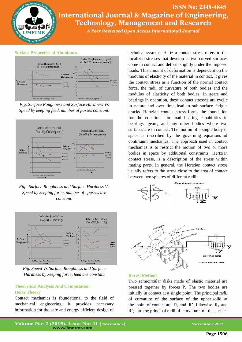
technical systems. Hertz a contact stress refers to the
localized stresses that develop as two curved surfaces
come in contact and deform slightly under the imposed
loads. This amount of deformation is dependent on the
modulus of elasticity of the material in contact. It gives
the contact stress as a function of the normal contact
force, the radii of curvature of both bodies and the
modulus of elasticity of both bodies. In gears and
bearings in operation, these contact stresses are cyclic
in nature and over time lead to sub-surface fatigue
cracks. Hertzian contact stress forms the foundation
for the equations for load bearing capabilities in
bearings, gears, and any other bodies where two
surfaces are in contact. The motion of a single body in
space is described by the governing equations of
continuum mechanics. The approach used in contact
mechanics is to restrict the motion of two or more
bodies in space by additional constraints. Hertzian
contact stress, is a description of the stress within
mating parts. In general, the Hertzian contact stress
usually refers to the stress close to the area of contact
between two spheres of different radii.
Boresi Method
Two semicircular disks made of elastic material are
pressed together by forces P. The two bodies are
initially in contact at a single point. The principal radii
of curvature of the surface of the upper solid at
the point of contact are R1 and R’1.Likewise R2 and
R’2 are the principal radii of curvature of the surface
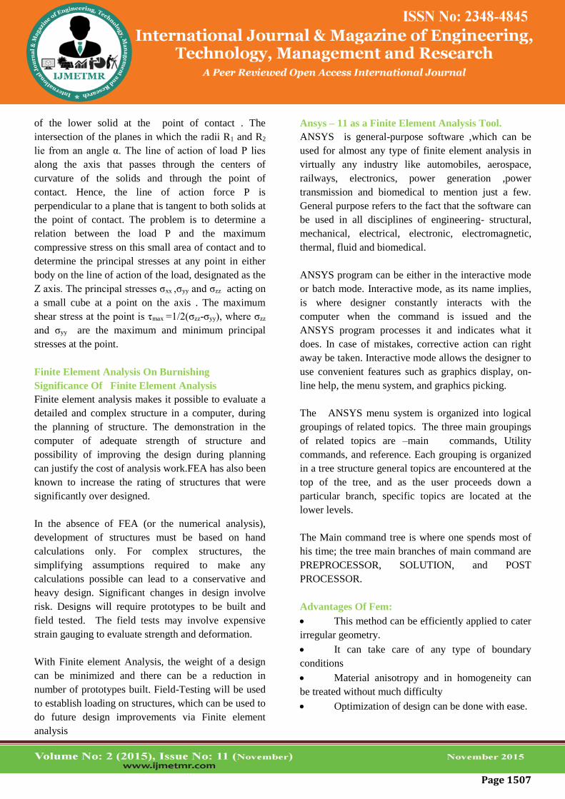
Page 1507
of the lower solid at the point of contact . The
intersection of the planes in which the radii R1 and R2
lie from an angle α. The line of action of load P lies
along the axis that passes through the centers of
curvature of the solids and through the point of
contact. Hence, the line of action force P is
perpendicular to a plane that is tangent to both solids at
the point of contact. The problem is to determine a
relation between the load P and the maximum
compressive stress on this small area of contact and to
determine the principal stresses at any point in either
body on the line of action of the load, designated as the
Z axis. The principal stresses σxx ,σyy and σzz acting on
a small cube at a point on the axis . The maximum
shear stress at the point is τmax =1/2(σzz-σyy), where σzz
and σyy are the maximum and minimum principal
stresses at the point.
Finite Element Analysis On Burnishing
Significance Of Finite Element Analysis
Finite element analysis makes it possible to evaluate a
detailed and complex structure in a computer, during
the planning of structure. The demonstration in the
computer of adequate strength of structure and
possibility of improving the design during planning
can justify the cost of analysis work.FEA has also been
known to increase the rating of structures that were
significantly over designed.
In the absence of FEA (or the numerical analysis),
development of structures must be based on hand
calculations only. For complex structures, the
simplifying assumptions required to make any
calculations possible can lead to a conservative and
heavy design. Significant changes in design involve
risk. Designs will require prototypes to be built and
field tested. The field tests may involve expensive
strain gauging to evaluate strength and deformation.
With Finite element Analysis, the weight of a design
can be minimized and there can be a reduction in
number of prototypes built. Field-Testing will be used
to establish loading on structures, which can be used to
do future design improvements via Finite element
analysis
Ansys – 11 as a Finite Element Analysis Tool.
ANSYS is general-purpose software ,which can be
used for almost any type of finite element analysis in
virtually any industry like automobiles, aerospace,
railways, electronics, power generation ,power
transmission and biomedical to mention just a few.
General purpose refers to the fact that the software can
be used in all disciplines of engineering- structural,
mechanical, electrical, electronic, electromagnetic,
thermal, fluid and biomedical.
ANSYS program can be either in the interactive mode
or batch mode. Interactive mode, as its name implies,
is where designer constantly interacts with the
computer when the command is issued and the
ANSYS program processes it and indicates what it
does. In case of mistakes, corrective action can right
away be taken. Interactive mode allows the designer to
use convenient features such as graphics display, on-
line help, the menu system, and graphics picking.
The ANSYS menu system is organized into logical
groupings of related topics. The three main groupings
of related topics are –main commands, Utility
commands, and reference. Each grouping is organized
in a tree structure general topics are encountered at the
top of the tree, and as the user proceeds down a
particular branch, specific topics are located at the
lower levels.
The Main command tree is where one spends most of
his time; the tree main branches of main command are
PREPROCESSOR, SOLUTION, and POST
PROCESSOR.
Advantages Of Fem:
This method can be efficiently applied to cater
irregular geometry.
It can take care of any type of boundary
conditions
Material anisotropy and in homogeneity can
be treated without much difficulty
Optimization of design can be done with ease.
Page 1508
Disadvantages Of Fem:
To solve the problem the approximations used
do not provide accurate results.
Stress value may vary from fine mesh to
average mesh analysis.
Analysis Of Contact Model Without Surface
Roughness Peaks
Table: Results of Mild Steel Contact model without
peaks.
Ansys results on Aluminum Contact Model without
peaks:
For
ce
(N)
Displacem
ent
Von
Misse
s
Stress
Von
Misses
Elastic
Strain
Von
misses
Plastic
Strain
50 0.001233 97.46
6
0.0015
91
0.0012
33
100 0.00254 139.3
19
0.0018
58
0.0013
02
250 0.616e-3 48.74
3
0.795e
-3
0.616e
-3
500 0.001233 97.46
6
0.0015
91
0.0012
33
Table Results of Aluminum Contact model without
peaks
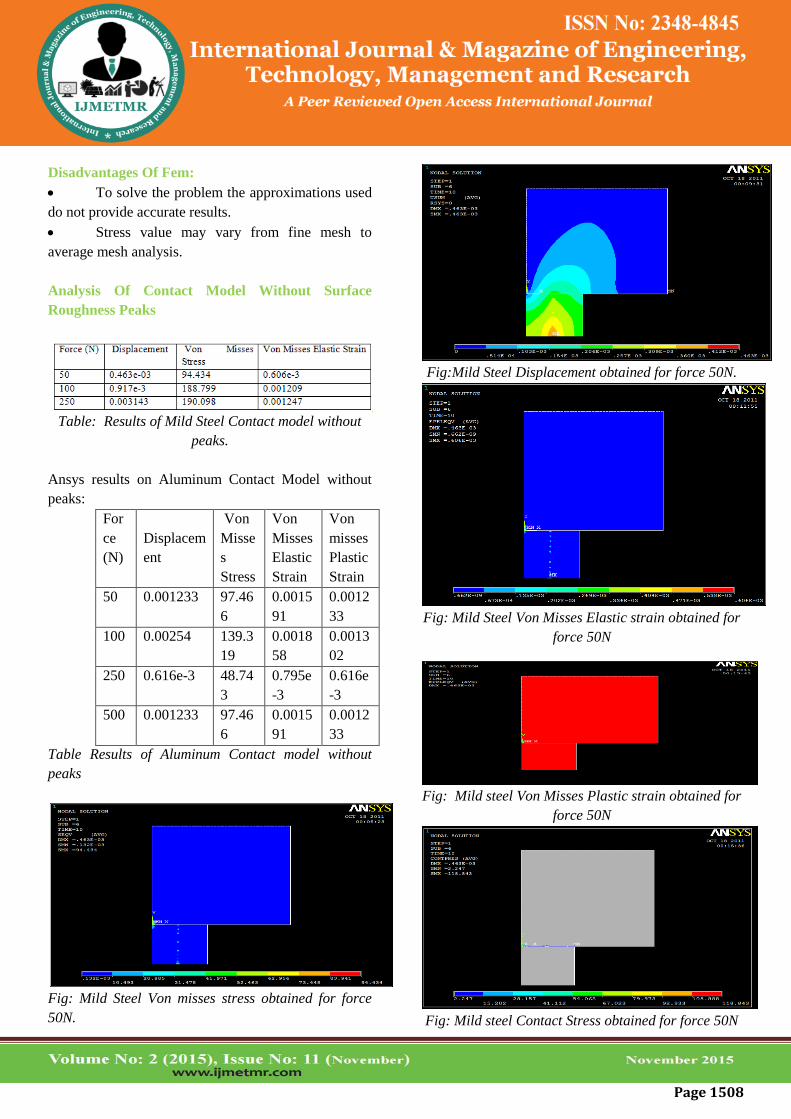
Fig: Mild Steel Von misses stress obtained for force
50N.
Fig:Mild Steel Displacement obtained for force 50N.
Fig: Mild Steel Von Misses Elastic strain obtained for
force 50N
Fig: Mild steel Von Misses Plastic strain obtained for
force 50N
Fig: Mild steel Contact Stress obtained for force 50N

Page 1509
Fig: Von misses stress Vs Displacement for Mild
Steel
ANALYSIS OF 3D CONTACT MODEL
Sl.N
o.
Forc
e
Displacem
ent
Von
misses
Stress
Elasti
c
Strain
Plastic
Strain
1 50 0.001395 163.38
7
0.817
e-3
-
2 250 0.007371 190.24
7
0.925
e-3
0.0075
3 500 0.017489 190.38
6
0.959
e-3
0.0431
65
Table Results of Mild Steel 3D Contact model
Sl.N
o.
For
ce
Displace
ment
Von
misse
s
Stress
Elastic
Strain
Plastic
Strain
1 50 0.003146 100.0
1
0.0013
34
0.478e
-3
2 250 0.018183 100.7
75
0.0013
44
0.0196
74
3 500 0.04861 101.6
8
0.0013
56
0.0422
2
Table Results of Aluminum 3D Contact model
Fig: loading Diagram for 3D contact Model.
Fig: Mild Steel Displacement obtained for 50N
Fig:Von Misses Stress obtained for 50N
Fig: Von Misses Elastic strain obtained for 50N
0
50
100
150
200
4.63E-04 9.17E-04 0.003143
Displacement
Von
moiss
es
stresss

Page 1510
Fig: Contact Status for 50N
Fig: Von Misses Stress for 3D Contact Model
of 500N
Fig: Displacement for 3D Contact Model of 500N
Fig: Von misses elastic strain for 3D Contact Model
of 500N
Fig: Von Misses Plastic strain for 3D Contact
Model of 500N
Fig: Contact status for 3D Contact Model of 500N
Fig: Aluminum Displacements for 3D Contact
Model of 50N
Fig: Aluminum Von misses Stress for 3D
Contact Model of 50N

Page 1511
Fig: Aluminum Von misses Elastic Strain for
3D Contact Model of 50N
Fig: Aluminum Von misses Plastic Strain for
3D Contact Model of 50N
Analysis of Contact Model with Surface
Roughness Peaks.
Maximum numbers of Surface Roughness
Peaks are in Contact with Tool.
Fig: loading Diagram of Contact
Model with surface roughness Peaks
Fig: Mild steel Displacement obtained for 100N force.
Fig: Von misses Stress for 100N Force.
Fig: Von misses Elastic Strain for 100N Force
Fig: Von misses Plastic Strain for 100N Force
Fig: Contact Status for 100N Force

Page 1512
Fig: Contact Stress for 100N Force
Analysis Of Work Piece Having Maximum Surface
Roughness Peaks.
Maximum Number of Surface Roughness Peaks is
38Nos.
Table: Result of Mild Steel analyses for 38No.Surface
roughness Peaks
Table: Result of Aluminum analysis for 38No.Surface
roughness Peaks
Fig Loading Diagram of Mild steel and
Aluminum
Fig: Mild steel Displacement obtained for 500N Force
Fig: Von Misses Stress obtained for 500N force
Fig: Von Misses Elastic strain obtained for 500N force
Number of Surface Roughness Peaks is 20Nos.
Table: Result of Mild Steel analysis for 20 Surface
Roughness Peaks
Table: Result of Aluminum analysis for 20 surface
roughness Peaks
Page 1513
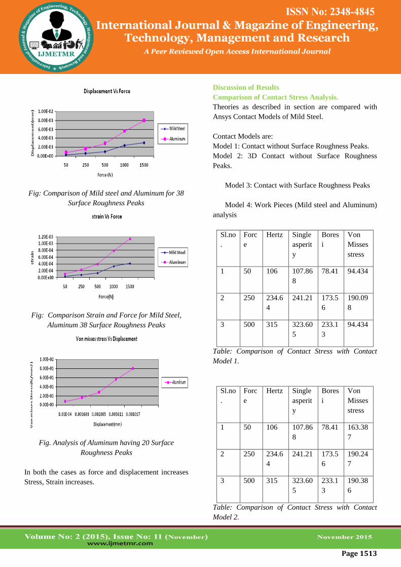
Fig: Comparison of Mild steel and Aluminum for 38
Surface Roughness Peaks
Fig: Comparison Strain and Force for Mild Steel,
Aluminum 38 Surface Roughness Peaks
Fig. Analysis of Aluminum having 20 Surface
Roughness Peaks
In both the cases as force and displacement increases
Stress, Strain increases.
Discussion of Results
Comparison of Contact Stress Analysis.
Theories as described in section are compared with
Ansys Contact Models of Mild Steel.
Contact Models are:
Model 1: Contact without Surface Roughness Peaks.
Model 2: 3D Contact without Surface Roughness
Peaks.
Model 3: Contact with Surface Roughness Peaks
Model 4: Work Pieces (Mild steel and Aluminum)
analysis
Sl.no
.
Forc
e
Hertz Single
asperit
y
Bores
i
Von
Misses
stress
1 50 106 107.86
8
78.41 94.434
2 250 234.6
4
241.21 173.5
6
190.09
8
3 500 315 323.60
5
233.1
3
94.434
Table: Comparison of Contact Stress with Contact
Model 1.
Sl.no
.
Forc
e
Hertz Single
asperit
y
Bores
i
Von
Misses
stress
1 50 106 107.86
8
78.41 163.38
7
2 250 234.6
4
241.21 173.5
6
190.24
7
3 500 315 323.60
5
233.1
3
190.38
6
Table: Comparison of Contact Stress with Contact
Model 2.

Page 1514
Sl.no
.
Forc
e
Hertz Single
asperit
y
Bores
i
Von
Misses
stress
1 50 106 107.86
8
78.41 109.31
2
2 250 234.6
4
241.21 173.5
6
-
3 500 315 323.60
5
233.1
3
-
Table: Comparison of Contact Stress with Contact
Model 3.
Sl.no
.
Forc
e
Hertz Single
asperit
y
Bores
i
Von
Misse
s
stress
1 50 106 107.86
8
78.41 8.025
2 250 234.6
4
241.21 173.5
6
16.05
3 500 315 323.60
5
233.1
3
26.322
Table: Comparison of Contact Stress with Contact
Model 4.
The Results Obtained indicates that Hertz Theory
yields similar results to FEM Model. The
Discrepancies in comparison of results are due to
reasons:
Approximate Materials Properties used in
simulation since text book values are
different from Practice.
The Contact analysis Prove to about 10 to
15% variation in results.
Conclusion
On the basis of Extensive Numerical and Experimental
Investigations of the Present work, the Following
conclusions:
1) The Results Shows that improvement in Surface
Roughness and increase in Surface Hardness are
achieved by application of Roller burnishing for Mild
steel and Aluminum Work pieces.
2) The surface roughness decreases with increase in
feed, burnishing speed, force and number of passes, to
a certain limit, and then it starts to increase with the
increase of each of the above-mentioned burnishing
parameters. Burnishing parameter values are: Feed
48tpi, Speed 399rpm, Force 250N and Passes 3 for
Mild Steel. Burnishing parameter values are: Feed
32tpi, Speed 399rpm, Force 250N and Passes 3 for
Aluminum.
3) The surface Hardness decreases with increase in
feed, burnishing speed, force and number of passes, to
a certain limit, and then it starts to increase with the
increase of each of the above-mentioned burnishing
parameters. For Example Optimum values are: Feed
32tpi, Speed 399rpm, Force 50N and Passes 3 for Mild
Steel and Feed 48tpi, Speed 399rpm, Force 500N and
Passes 3 for Aluminum.
4) Regression analysis yields that Surface Hardness
depends on decreasing order of factors like Feed,
Force, Passes and Speed for Mild Steel and Surface
Roughness depends on decreasing order of factors like
Speed, Passes, Feed and Force for Mild Steel.
5) Regression analysis yields that Surface Hardness
and surface Roughness depends on increasing order of
factors like Passes, Speed, Feed and Force for Mild
Steel and Aluminum.
6) As Force increases Stress increases up to certain
limit and decreases due to Work Hardening Effect,
Loss of ductility of material.
7) All Models are Compared Theoretically and
Experimentally the results Obtained indicates that
Hertz Theory yields similar results to FEM Model.
8) The Discrepancies In comparison of results are due
to reasons:
Approximate Materials Properties used in
simulation since text book values are different from
Practice.
The Contact analysis Prove to about 10 to 15%
variation in results.

Page 1515
Future Scope
Investigations are making use of different size
of rollers is used to conduct tests on the components.
Investigations on the effect force, feed, Speed
and Passes to determine the optimal burnishing
parameters on corrosion resistance, since surface
roughness has great influence on corrosion resistance.
Dynamic analysis can be performed for
different Contact Models subjected to various Loads,
especially FEM analysis.
Different Modern Statistical approaches like
Taugchi Technique, Genetic Algorithm and ANOVAs
can be performed to Optimize Parameters like Speed,
Feed, Force and Number of Passes.
Contact Stress analysis can be performed on
different materials like Copper and Titanium etc.
REFERENCES
1) C. S. Jawalkar and R. S. Walia., Study Of
Roller Burnishing Process On En-8 Specimens Using
Design Of Experiments Journal of Mechanical
Engineering Research Vol. 1(1) pp. 038-045.
2) K.Eshwar Prasad, R.Murali Krishna.,
Experimental Investigation and Finite Element
Analysis For The Study Of Residual Stresses In Roller
Burnished Components. - International Journal of
Applied Engineering Research ISSN0973-4562
Volume1.
3) M.H. El-Axir., An Investigation In To Roller
Burnishing - International Journal of Machine Tools &
Manufacture 40 (2000) 1603–1617.
4) J. Naga Malleswara Rao, A. Chenna Kesava
Reddy and P.V. Rama Rao. Design And Fabrication
Of New Type Of Dynamometer To Measure Radial
Component Of Cutting Force And Experimental
Investigation Of Optimum Burnishing Force In Roller
Burnishing Process - Indian Journal of Science and
Technology Vol. 3 No. 7 ISSN: 0974- 6846.
5) Y. C. Lin Æ S. W. Wang Æ H.-Y. Lai .,The
Relationship Between Surface Roughness And
Burnishing Factor In Burnishing Process - Int J Adv
Manuf Technol (2004) 23: 666–671.
6) W. Bouzid Sa¨ı · K.Sa¨I .,Finite Element
Modeling Of Burnishing Of AISI 1042 steel - Int J
Adv Manuf Technol 25: 460–465.
7) M. Ne´mat and A. C. Lyons .,An Investigation
of the Surface Topography of Ball Burnished Mild
Steel and Aluminium - Int J Adv Manuf Technol
16:469–473.
8) Dr. Safwan M.A. Al-Qawabah.,Investigation
of Roller Burnishing on Zamac5 Alloyed by Copper,
Journal of Applied Sciences Research, 5(10): 1796-
1801, 2009.
9) Hongyun Luo · Jianying Liu · LijiangWang ·
Qunpeng Zhong.,Investigation of the burnishing
process with PCD tool on non-ferrous metals, Int J
Adv Manuf Techno 25: 454–459.
10) N.S.M. El-Tayeb, K.O. Low, P.V. Brevern
.,Influence of roller burnishing contact width and
burnishing orientation on surface quality and
tribological behavior of Aluminum 6061, Journal of
Materials Processing Technology 186 272–278.
11) A.M.Hassan., An investigation in to the
surface characteristics of burnished cast Al – Cu
Alloys – Int. J. Mach. Tools Manufact. Vol. 37, No.
6. pp. 813-821. 1997.
12) Sorin Cananau.,3D contact Stress Analysis for
spur gears - National Tribology Conference.2003 ISSN
1221-4590.
13) C.Y.Seemikeri, S.B.Mahagaonkar &
P.K.Brahmankar.,Parametric Studies of Low

Page 1516
Burnishing on the surface enhancement of AA 7075-
T6.
14) T.A.El-.Taweel – M.H.El-Axir .,Analysis and
optimization of the ball burnishing process through the
Taguchi technique .
15) Fritz Klocke • Vladimir Bäcker • Hagen
Wegner •Björn Feldhaus •Roland Hessert Influence of
process and geometry parameters on the surface layer
state after rolling burnishing IN718
16) G.G. Adams , M. Nosonovsky. Contact
Modeling – forces - Tribology International 33 (2000)
431- 442
17) A.J.Black, E.M.Kopalinsky, P.L.B.Oxley.,
Analysis and Experimental investigation of a
simplified burnishing process.
18) Malleswara Rao J. N. 1 , Chenna Kesava Red
dy A. 2 , Rama Rao P. V. 3 1-442.,
The effect of roller burnishing on surface hardness and
surface roughness on mild steel specimens –
IJAEVolume1,No4,2011.
19) Khalid. S. Rababa and Mayas Mohammad Al-
mahasne .,Effect of Roller Burnishing on the
Mechanical Behavior and Surface Quality of O1 Alloy
Steel -- Research Journal of Applied Sciences,
Engineering and Technology 3(3): 227-233, 2011
20) Adnan Akkurt. Comparison of Roller
Burnishing Method with Other Hole Surface Finishing
Processes Applied on AISI 304 Austenitic Stainless
Steel.
Related Documents