Distributed Generation and Integration with National Grid

Welcome message from author
This document is posted to help you gain knowledge. Please leave a comment to let me know what you think about it! Share it to your friends and learn new things together.
Transcript
Distributed Generation and Integration with National Grid


Group Members
• Syed Faizan Ali (EE-040)• Syed Ibtihaj (EE-057)• Dareer Bin Khalid (EE-061)• Muhammad Ali Siddiqui (EE-062)
Introduction
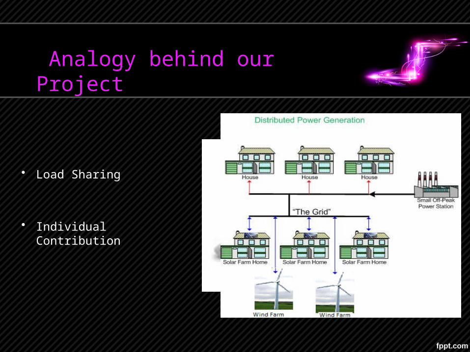
Analogy behind our Project
• Load Sharing
• Individual Contribution
Background Facts
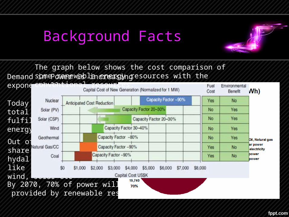
Demand in Power is increasing exponentially
Out of which 16% is the share ofhydal and 3% of renewable likewind, solar etc
Today 19% of the world’s total energy requirement is fulfilled via renewable energy
By 2070, 70% of power will be provided by renewable resources
The graph below shows the cost comparison of some renewable energy resources with the conventional resources.
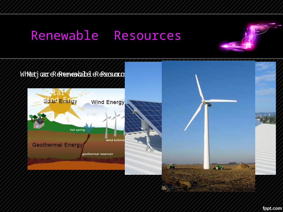
Renewable Resources
What are Renewable Resources? Major Renewable Resources
Solar EnergyWind Energy
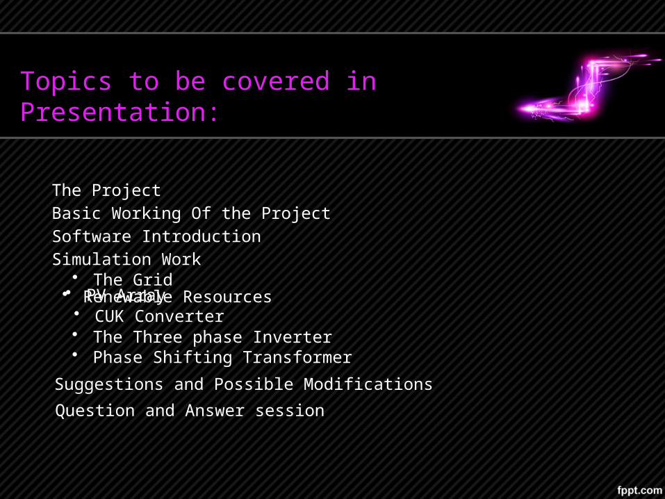
Topics to be covered in Presentation:
The ProjectBasic Working Of the ProjectSoftware Introduction
• The GridSimulation Work
• CUK Converter
Suggestions and Possible ModificationsQuestion and Answer session
• Renewable Resources
• The Three phase Inverter• Phase Shifting Transformer
• PV Array
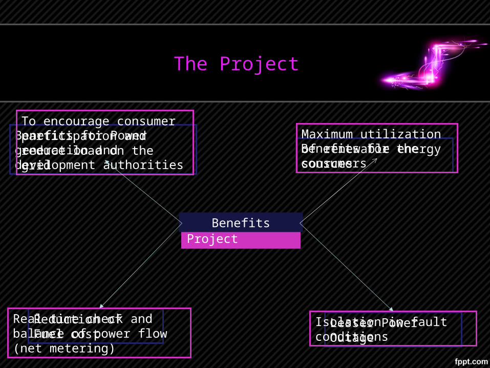
The Project
Aim of The ProjectBenefits
Benefits for Power generation and development authorities Benefits for the consumers
Reduction of Fuel cost Lesser Power Outage
Maximum utilization of renewable energy sources
To encourage consumer participation and reduce load on the grid
Real time check and balance of power flow (net metering)
Isolation in fault conditions
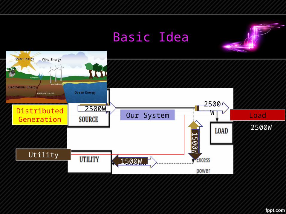
Basic Idea
2000W
500W
4000W
2500
W
2500W
500W
Distributed Generation Our System
Utility
Load
2500W
2500W
2500W
1500W
1500W
2500W 2500W
Simulation Work
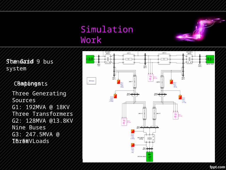
The Grid
Components:
Standard 9 bus system
Three Generating Sources
Three Transformers
Nine Buses
Three Loads
Ratings
G1: 192MVA @ 18KV
G2: 128MVA @13.8KV
G3: 247.5MVA @ 16.5KV
Simulation Work
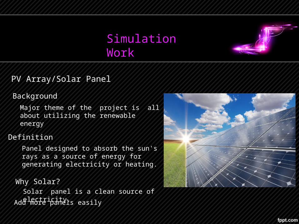
PV Array/Solar Panel
Background
Definition
Major theme of the project is all about utilizing the renewable energy
Solar panel is a clean source of electricity.
Panel designed to absorb the sun's rays as a source of energy for generating electricity or heating.
Why Solar?
Add more panels easily
The Sun’s Input Irradiation Pattern to Solar Cells
Simulation Work
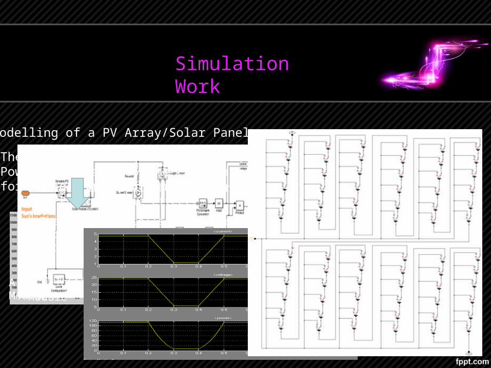
Modelling of a PV Array/Solar Panel
A solar panel is a module made up of many small solar cells.
Solar cells operate on the principle of Photoelectric effect.
The number of cells in an array depend upon the desired requirement of electricity.
The Output Current, Voltage and Power Delivered by the PV Array for the given Input Irradiation
A 6 Cell Solar Module x12A 72 Cell Solar Module
Simulation Work
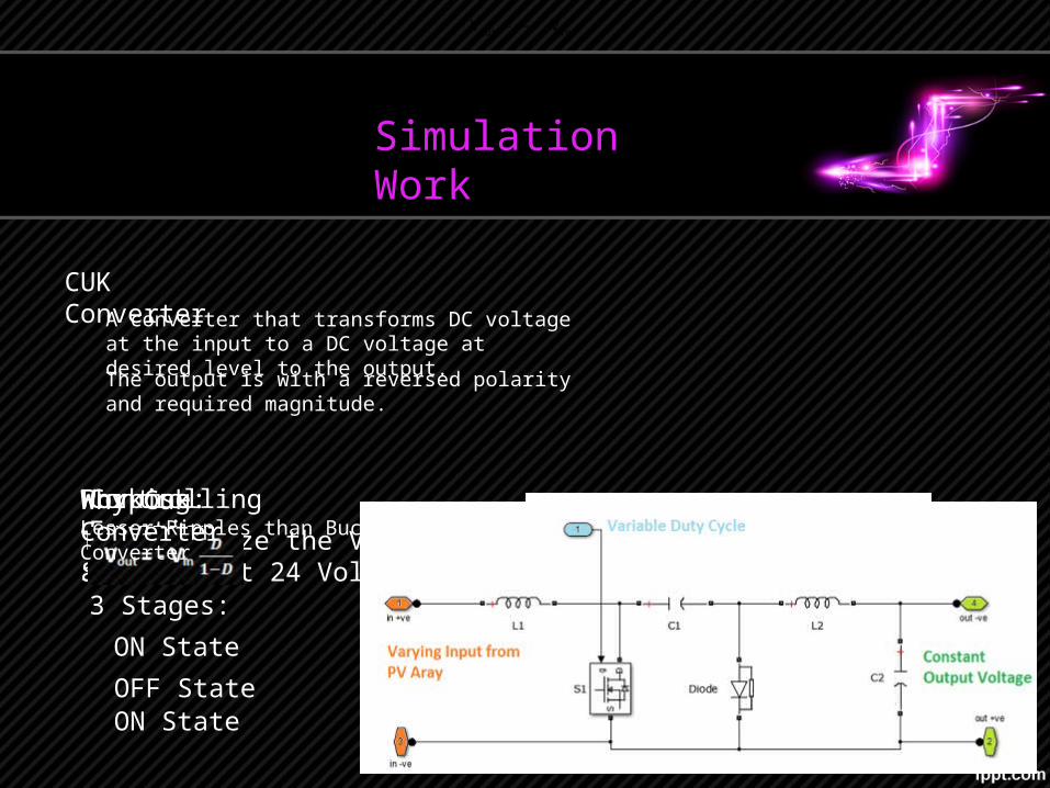
CUK ConverterA converter that transforms DC voltage at the input to a DC voltage at desired level to the output.
The output is with a reversed polarity and required magnitude.
Working:The MOSFET SwitchPurpose:To Stabilize the Voltage at constant 24 Volts3 Stages:
ON StateOFF StateON State
Controlling Equation
Vout = - Vin
Why Cuk ConverterLesser Ripples than Buck Boost Converter
Simulation Work
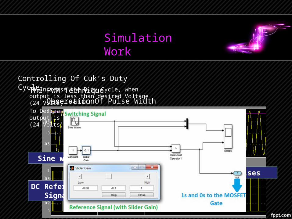
Controlling Of Cuk’s Duty CycleTo Increase the Duty Cycle, when output is less than desired Voltage (24 Volts)
To Decrease the Duty Cycle, when output is greater than desired Voltage (24 Volts)
Sine wave
DC Reference Signal
Comparator Pulses
The PWM TechniqueGeneration Of Pulse WidthObservation
Simulation Work
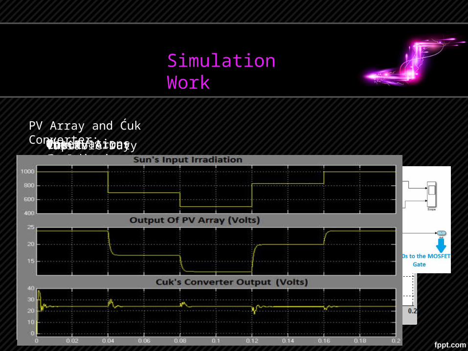
PV Array and Ćuk Converter:
Input IrradiationThe PV ArrayĆuk ConverterVariable Duty CycleObservations
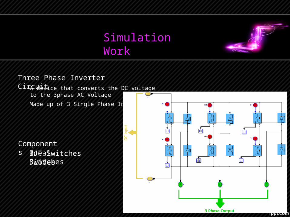
Three Phase Inverter Circuit
ComponentsBJT SwitchesDiodesIdeal Switches
Simulation Work
A device that converts the DC voltage to the 3phase AC Voltage
Made up of 3 Single Phase Inverter
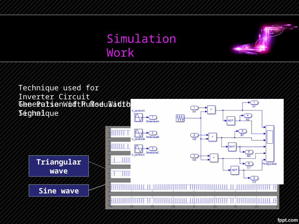
Technique used for Inverter Circuit
The Pulse Width Modulation TechniqueGeneration of Pulse Width Signal
Triangular wave
Sine wave
Comparator Gate Pulses
Simulation Work
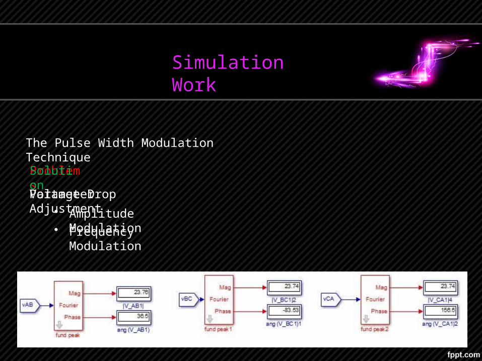
The Pulse Width Modulation Technique
Simulation Work
Problems
Voltage Drop
Solution
Parameter Adjustment• Amplitude Modulation• Frequency Modulation
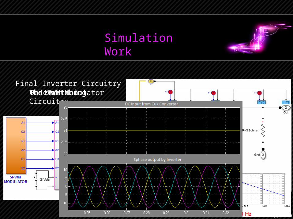
Final Inverter CircuitryThe PWM ModulatorThe Switching CircuitryFilterObservation:
Simulation Work
Simulation Work
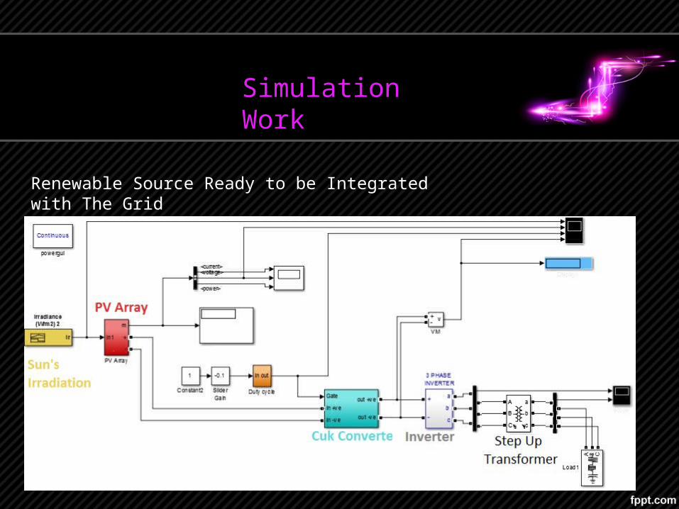
Renewable Source Ready to be Integrated with The Grid
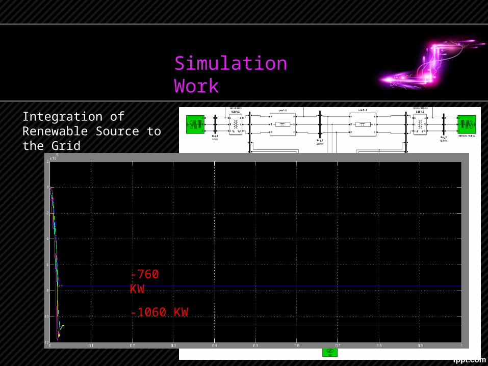
Integration of Renewable Source to the Grid
Simulation Work
-760 KW
-1060 KW
Simulation Work
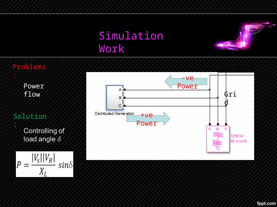
Problems:
+ve Power
Grid
-ve PowerPower flow
Solution:
Simulation Work
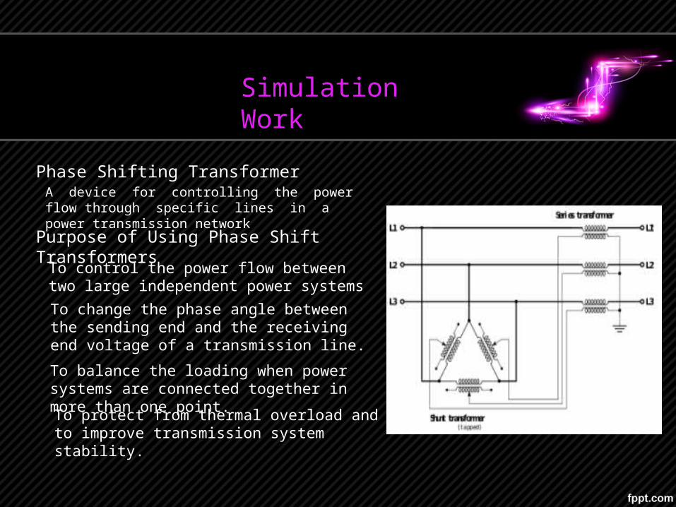
Phase Shifting TransformerA device for controlling the power flow through specific lines in a power transmission network
Purpose of Using Phase Shift Transformers
To control the power flow between two large independent power systems To change the phase angle between the sending end and the receiving end voltage of a transmission line.
To balance the loading when power systems are connected together in more than one point.
To protect from thermal overload and to improve transmission system stability.
Simulation Work
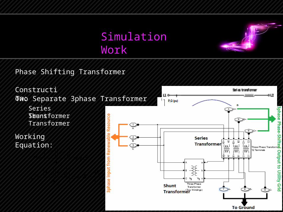
Phase Shifting Transformer
Construction:Two Separate 3phase Transformer
Series TransformerShunt Transformer
Working Equation:
𝑃=|𝑉 𝑠||𝑉 𝑅|
𝑋 𝐿𝑠𝑖𝑛 δ
𝑄=|𝑉 𝑠||𝑉 𝑅|
𝑋𝐿(𝑐𝑜𝑠 δ− V R
V S )
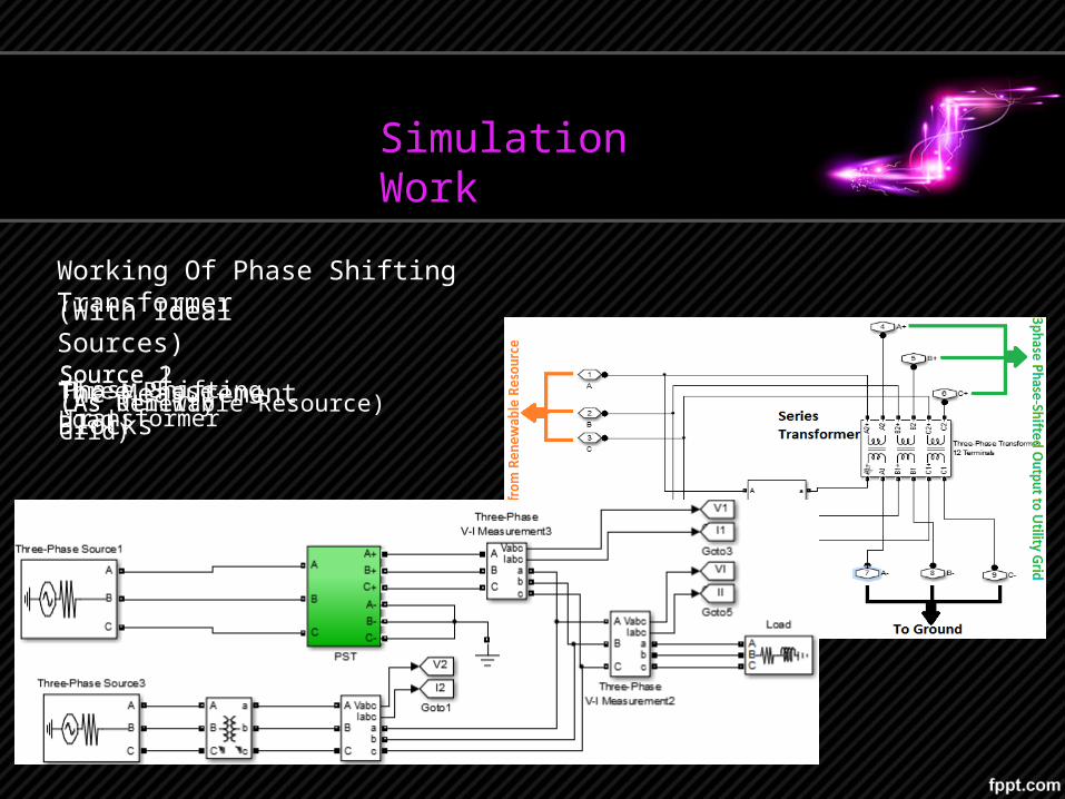
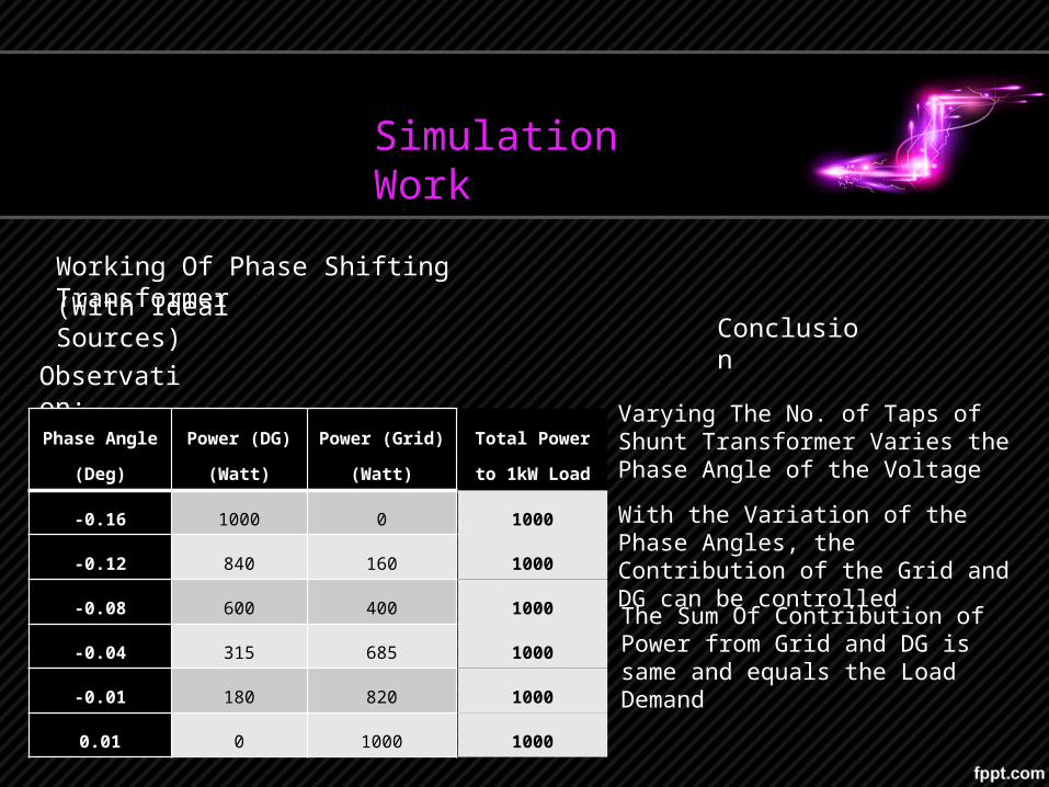
Working Of Phase Shifting Transformer(With Ideal Sources)
Source 1(As Utility Grid)Source 2(As Renewable Resource)Phase Shifting TransformerThree Phase LoadThe Measurement Blocks
Simulation Work
Working Of Phase Shifting Transformer(With Ideal Sources)
Simulation Work
Observation:
Phase Angle(Deg)
Power (DG)(Watt)
Power (Grid)(Watt)
-0.16 1000 0
-0.12 840 160
-0.08 600 400
-0.04 315 685
-0.01 180 820
0.01 0 1000
Conclusion
Varying The No. of Taps of Shunt Transformer Varies the Phase Angle of the Voltage
With the Variation of the Phase Angles, the Contribution of the Grid and DG can be controlled
The Sum Of Contribution of Power from Grid and DG is same and equals the Load Demand
Total Power to 1kW Load
1000
1000
1000
1000
1000
1000
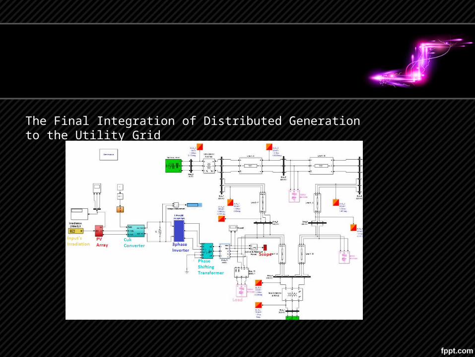
The Final Integration of Distributed Generation to the Utility Grid
Suggestions and Possible Modifications
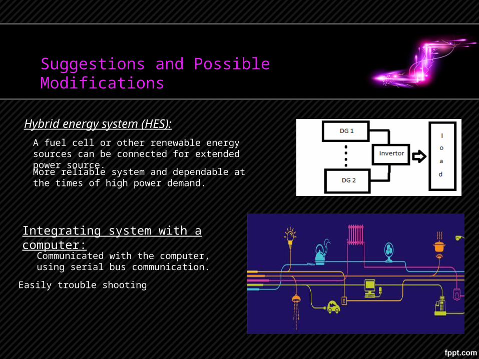
Hybrid energy system (HES):
Integrating system with a computer:
A fuel cell or other renewable energy sources can be connected for extended power source.
More reliable system and dependable at the times of high power demand.
Communicated with the computer, using serial bus communication.
Easily trouble shooting
Suggestions and Possible Modifications
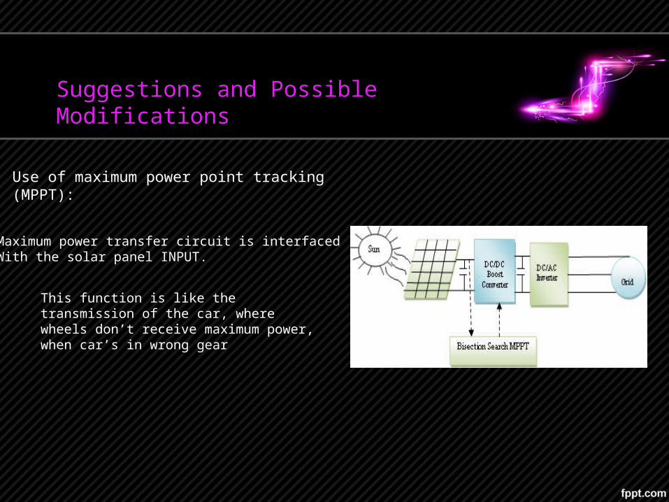
Use of maximum power point tracking (MPPT):
This function is like the transmission of the car, where wheels don’t receive maximum power, when car’s in wrong gear
Maximum power transfer circuit is interfacedWith the solar panel INPUT.

ThankYou
Related Documents