1 www.nasa.gov Electrified Aircraft Propulsion Systems: Potential Failure Modes and Failure Mitigation Strategies Donald L. Simon & Joseph W. Connolly NASA Glenn Research Center EnergyTech 2019 Cleveland, OH October 21-25, 2019

Welcome message from author
This document is posted to help you gain knowledge. Please leave a comment to let me know what you think about it! Share it to your friends and learn new things together.
Transcript
1www.nasa.gov
Electrified Aircraft Propulsion Systems: Potential Failure Modes and Failure
Mitigation Strategies
Donald L. Simon & Joseph W. Connolly
NASA Glenn Research Center
EnergyTech 2019
Cleveland, OH
October 21-25, 2019
2
Outline
• Electrified Aircraft Propulsion (EAP) Background
• Overview of EAP Fault Management Process
• EAP System Failure Modes and Effects• Subsystem failure modes and effects
• Coupled subsystem failure modes and effects
• Example of Potential Failure Modes and Failure Mitigation Strategies for a NASA EAP Concept Aircraft
• Summary
3
Electrified Aircraft Propulsion (EAP) Background
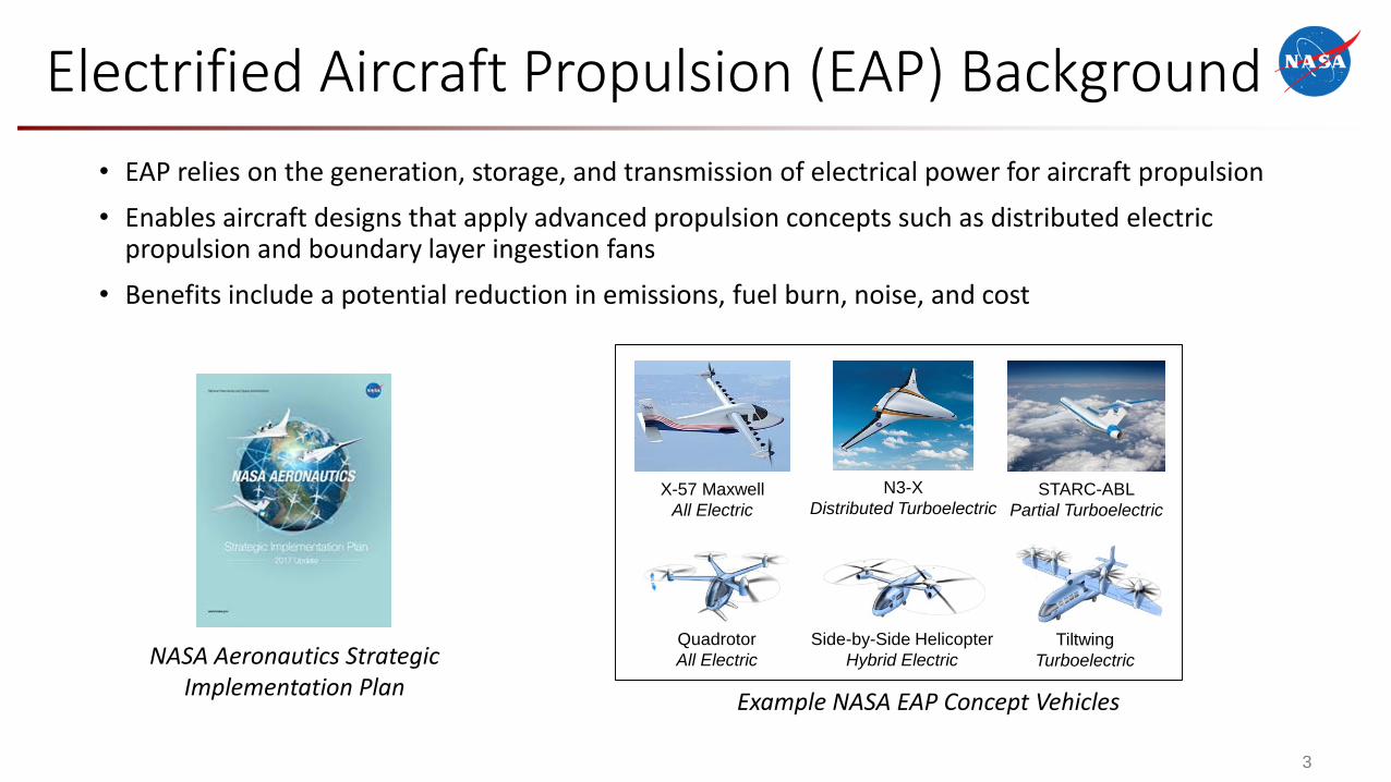
• EAP relies on the generation, storage, and transmission of electrical power for aircraft propulsion
• Enables aircraft designs that apply advanced propulsion concepts such as distributed electric propulsion and boundary layer ingestion fans
• Benefits include a potential reduction in emissions, fuel burn, noise, and cost
Example NASA EAP Concept Vehicles
N3-X
Distributed TurboelectricX-57 Maxwell
All Electric
Quadrotor
All Electric
Side-by-Side Helicopter
Hybrid Electric
Tiltwing
Turboelectric
STARC-ABL
Partial Turboelectric
NASA Aeronautics Strategic Implementation Plan
4
Electrified Aircraft Propulsion (EAP) System Fault Management
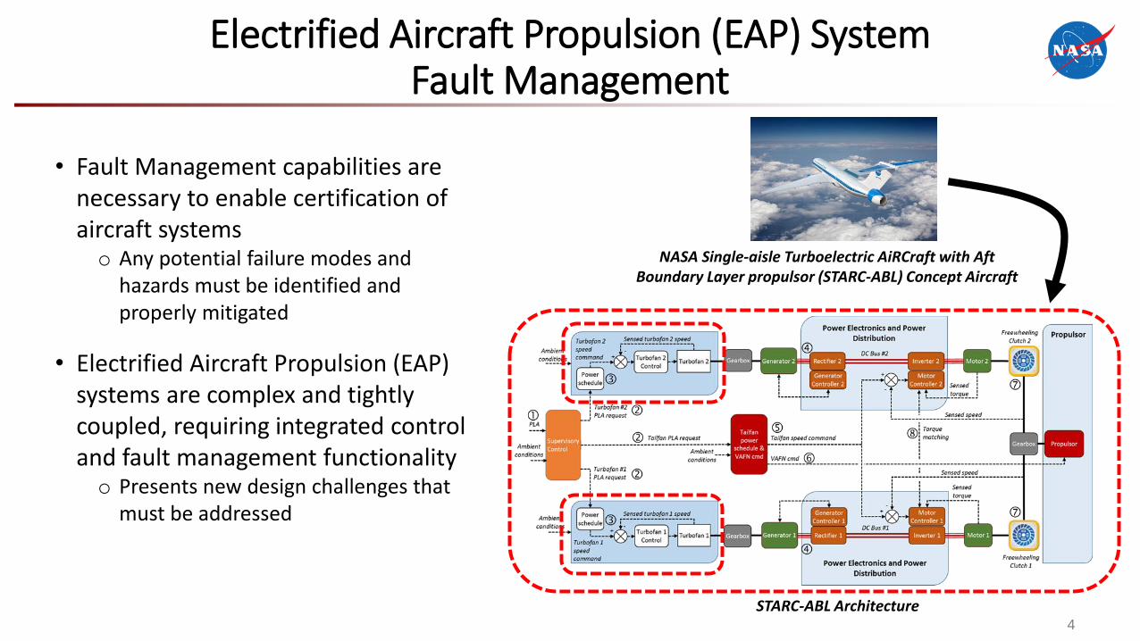
• Fault Management capabilities are necessary to enable certification of aircraft systemso Any potential failure modes and
hazards must be identified and properly mitigated
• Electrified Aircraft Propulsion (EAP) systems are complex and tightly coupled, requiring integrated control and fault management functionalityo Presents new design challenges that
must be addressed
NASA Single-aisle Turboelectric AiRCraft with Aft Boundary Layer propulsor (STARC-ABL) Concept Aircraft
STARC-ABL Architecture
5
Overview of EAP System Components
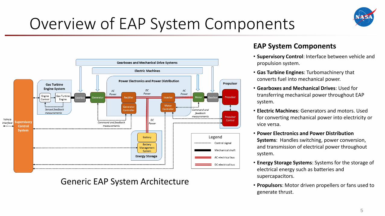
Generic EAP System Architecture
EAP System Components• Supervisory Control: Interface between vehicle and
propulsion system.
• Gas Turbine Engines: Turbomachinery that converts fuel into mechanical power.
• Gearboxes and Mechanical Drives: Used for transferring mechanical power throughout EAP system.
• Electric Machines: Generators and motors. Used for converting mechanical power into electricity or vice versa.
• Power Electronics and Power Distribution Systems: Handles switching, power conversion, and transmission of electrical power throughout system.
• Energy Storage Systems: Systems for the storage of electrical energy such as batteries and supercapacitors.
• Propulsors: Motor driven propellers or fans used to generate thrust.
6
EAP Subsystem Failure Modes and Effects
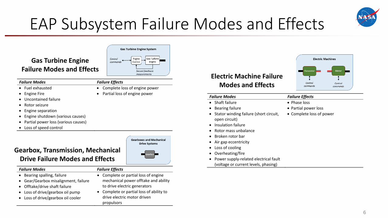
Gas Turbine Engine Failure Modes and Effects
Failure Modes Failure Effects
Bearing spalling, failure
Gear/Gearbox misalignment, failure
Offtake/drive shaft failure
Loss of drive/gearbox oil pump
Loss of drive/gearbox oil cooler
Complete or partial loss of engine mechanical power offtake and ability to drive electric generators
Complete or partial loss of ability to drive electric motor driven propulsors
Gearbox, Transmission, Mechanical Drive Failure Modes and Effects
Failure Modes Failure Effects
Shaft failure
Bearing failure
Stator winding failure (short circuit, open circuit)
Insulation failure
Rotor mass unbalance
Broken rotor bar
Air gap eccentricity
Loss of cooling
Overheating/fire
Power supply-related electrical fault (voltage or current levels, phasing)
Phase loss
Partial power loss
Complete loss of power
Electric Machine Failure Modes and Effects
Failure Modes Failure Effects
Fuel exhausted
Engine Fire
Uncontained failure
Rotor seizure
Engine separation
Engine shutdown (various causes)
Partial power loss (various causes)
Loss of speed control
Complete loss of engine power
Partial loss of engine power
7
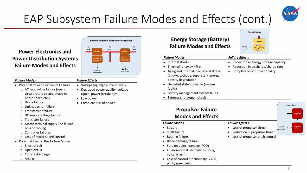
EAP Subsystem Failure Modes and Effects (cont.)
Failure Modes Failure Effects
Potential Power Electronics Failures o AC supply-line failure (open-
circuit, short-circuit, phase-to-phase short, etc.)
o Diode failure o Link capacitor failure o Transformer failure o DC supply voltage failure o Transistor failure o Motor terminal supply line failure o Loss of cooling o Controller failures o Loss of motor speed control
Potential Electric Bus Failure Modes o Short circuit o Open circuit o Corona discharge o Arcing
Voltage sag, high current levels
Degraded power quality (voltage ripple, power instabilities)
Low power
Complete loss of power
Power Electronics and Power Distribution Systems Failure Modes and Effects
Failure Modes Failure Effects
Internal shorts
Thermal runaway / fire
Aging and internal mechanical stress (anode, cathode, separator), energy density degradation
Depleted state of charge (various faults)
Battery management system faults
External short/open circuit
Reduction in energy storage capacity
Reduction in discharge/charge rate
Complete loss of functionality
Energy Storage (Battery) Failure Modes and Effects
Failure Modes Failure Effects
Seizure
Shaft failure
Bearing failure
Blade damage/failure
Foreign object damage (FOD)
Environmental particulates (icing, volcanic ash)
Loss of control functionality (VAFN, pitch, speed, etc.)
Loss of propulsor thrust
Reduction in propulsor thrust
Loss of propulsor pitch control
Propulsor Failure Modes and Effects
8
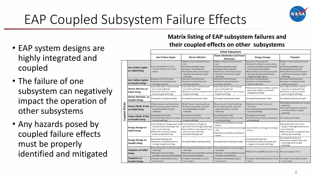
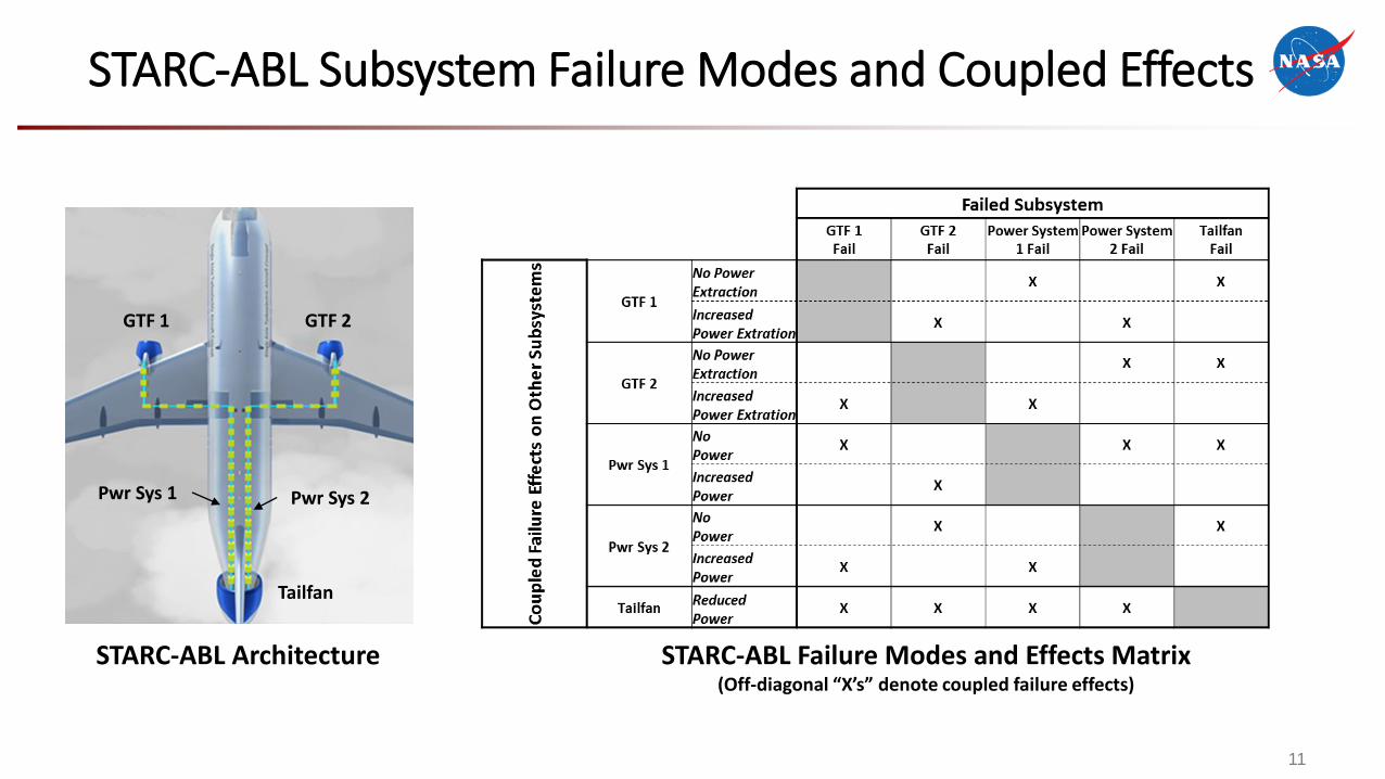
EAP Coupled Subsystem Failure EffectsMatrix listing of EAP subsystem failures and their coupled effects on other subsystems• EAP system designs are
highly integrated and coupled
• The failure of one subsystem can negatively impact the operation of other subsystems
• Any hazards posed by coupled failure effects must be properly identified and mitigated
9
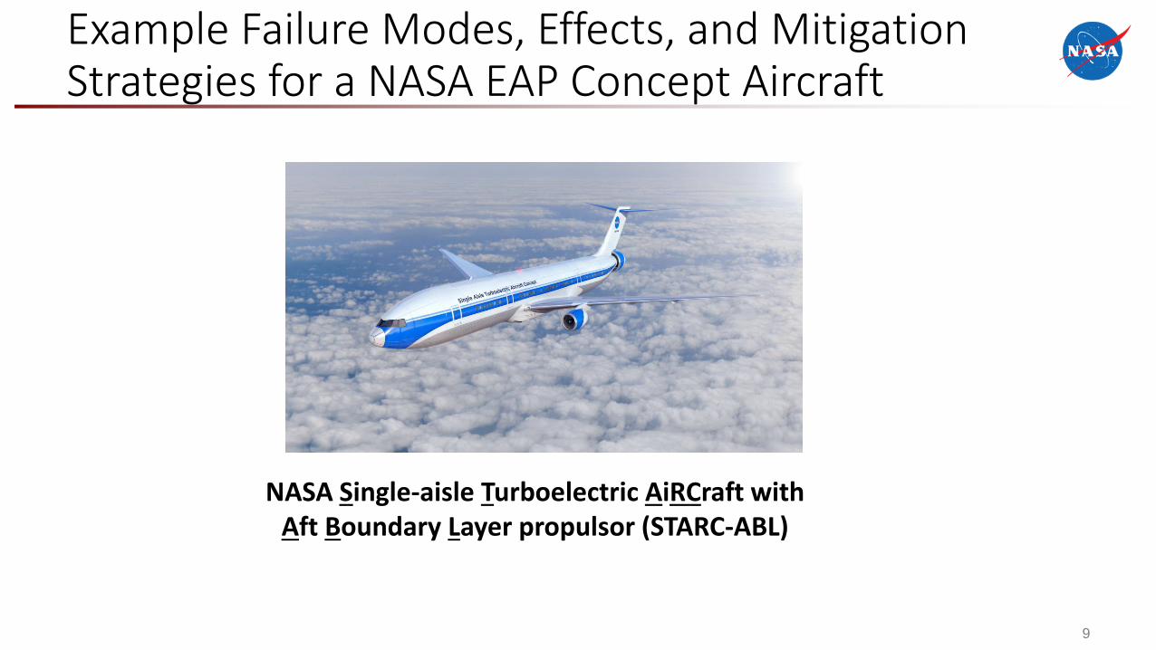
Example Failure Modes, Effects, and Mitigation Strategies for a NASA EAP Concept Aircraft
NASA Single-aisle Turboelectric AiRCraft with Aft Boundary Layer propulsor (STARC-ABL)
10
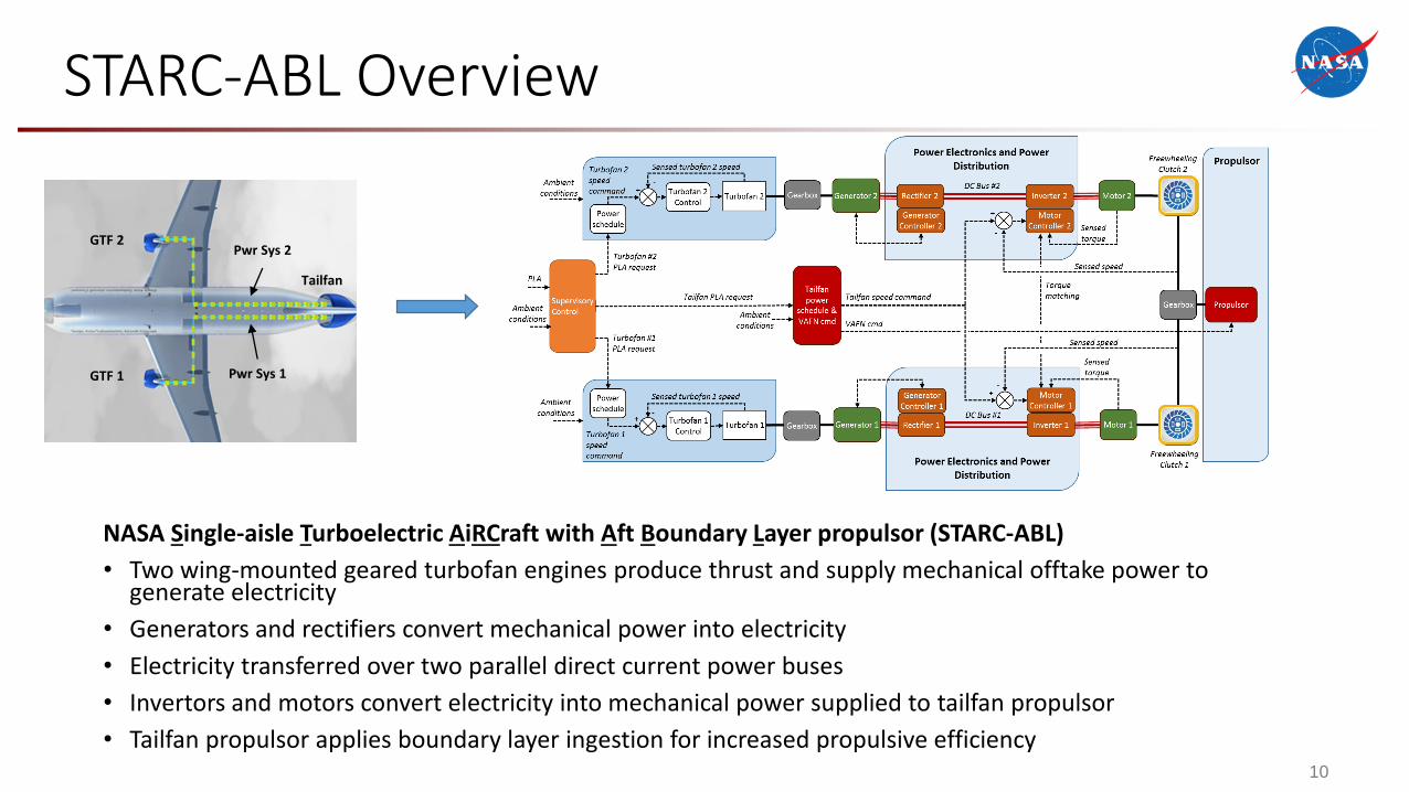
STARC-ABL Overview
NASA Single-aisle Turboelectric AiRCraft with Aft Boundary Layer propulsor (STARC-ABL)
• Two wing-mounted geared turbofan engines produce thrust and supply mechanical offtake power to generate electricity
• Generators and rectifiers convert mechanical power into electricity
• Electricity transferred over two parallel direct current power buses
• Invertors and motors convert electricity into mechanical power supplied to tailfan propulsor
• Tailfan propulsor applies boundary layer ingestion for increased propulsive efficiency
GTF 1
GTF 2
Tailfan
Pwr Sys 1
Pwr Sys 2
11
STARC-ABL Subsystem Failure Modes and Coupled Effects
GTF 1 GTF 2
Tailfan
Pwr Sys 1 Pwr Sys 2
STARC-ABL Architecture STARC-ABL Failure Modes and Effects Matrix(Off-diagonal “X’s” denote coupled failure effects)
12
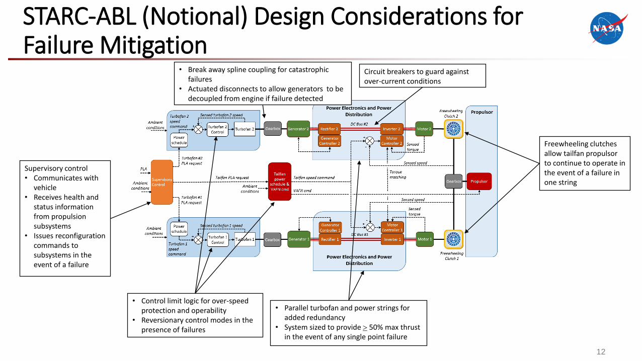
STARC-ABL (Notional) Design Considerations for Failure Mitigation
Freewheeling clutches allow tailfan propulsorto continue to operate in the event of a failure in one string
• Parallel turbofan and power strings for added redundancy
• System sized to provide 50% max thrust in the event of any single point failure
• Break away spline coupling for catastrophic failures
• Actuated disconnects to allow generators to be decoupled from engine if failure detected
• Control limit logic for over-speed protection and operability
• Reversionary control modes in the presence of failures
Circuit breakers to guard against over-current conditions
Supervisory control• Communicates with
vehicle• Receives health and
status information from propulsion subsystems
• Issues reconfiguration commands to subsystems in the event of a failure
13
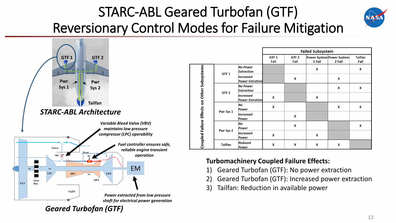
STARC-ABL Geared Turbofan (GTF)Reversionary Control Modes for Failure Mitigation
Turbomachinery Coupled Failure Effects:1) Geared Turbofan (GTF): No power extraction2) Geared Turbofan (GTF): Increased power extraction3) Tailfan: Reduction in available power
GTF 1 GTF 2
Tailfan
PwrSys 1
PwrSys 2
STARC-ABL Architecture
Geared Turbofan (GTF)
Power extracted from low pressure shaft for electrical power generation
Variable Bleed Valve (VBV) maintains low pressure
compressor (LPC) operability
Fuel controller ensures safe, reliable engine transient
operation
EM
14
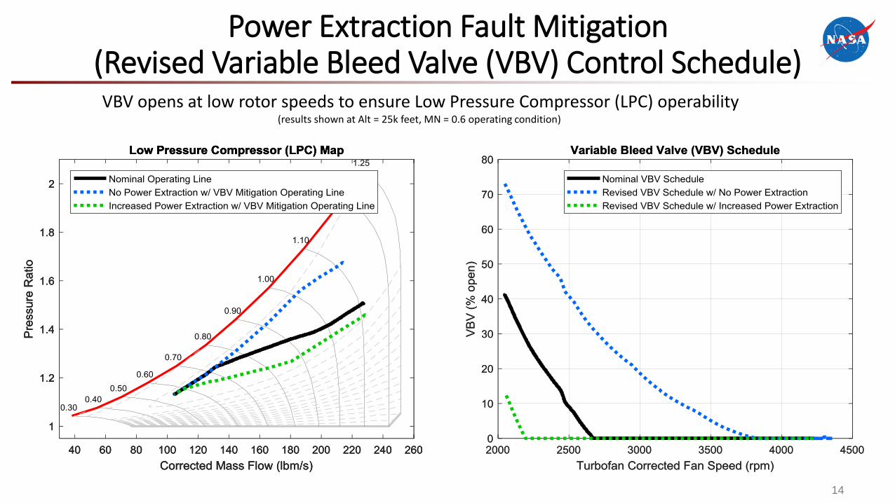
Power Extraction Fault Mitigation (Revised Variable Bleed Valve (VBV) Control Schedule)
VBV opens at low rotor speeds to ensure Low Pressure Compressor (LPC) operability(results shown at Alt = 25k feet, MN = 0.6 operating condition)
15
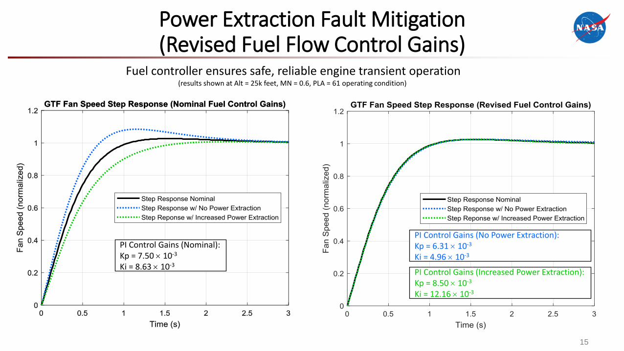
Power Extraction Fault Mitigation (Revised Fuel Flow Control Gains)
Fuel controller ensures safe, reliable engine transient operation(results shown at Alt = 25k feet, MN = 0.6, PLA = 61 operating condition)
PI Control Gains (Nominal):Kp = 7.50 10-3
Ki = 8.63 10-3
PI Control Gains (No Power Extraction):Kp = 6.31 10-3
Ki = 4.96 10-3
PI Control Gains (Increased Power Extraction):Kp = 8.50 10-3
Ki = 12.16 10-3
16
Summary
• Electrified Aircraft Propulsion (EAP) systems are novel, tightly integrated designso Many candidate EAP architectures exist, each presenting
unique failure modeso Any potential hazards associated with failures must be
identified and properly mitigated to enable certification
• Research and development is necessary to ensure appropriate fault management strategies for EAPo Fault management needed at both at the subsystem and
system levelo Expected to require multi-disciplinary, system-level design
approaches
17
• This work was conducted under the NASA Advanced Air Vehicles Program, Advanced Air Transport Technology Project
Acknowledgments
Related Documents