Vol.:(0123456789) 1 3 Automotive Innovation (2020) 3:299–316 https://doi.org/10.1007/s42154-020-00124-y Thermal Management of Electrified Propulsion System for Low‑Carbon Vehicles Bo Li 1 · Huang Kuo 1 · Xuehui Wang 1 · Yiyi Chen 2 · Yangang Wang 2 · David Gerada 1 · Sean Worall 3 · Ian Stone 3 · Yuying Yan 1 Received: 30 March 2020 / Accepted: 29 October 2020 / Published online: 2 December 2020 © The Author(s) 2020 Abstract An overview of current thermal challenges in transport electrification is introduced in order to underpin the research devel- opments and trends of recent thermal management techniques. Currently, explorations of intelligent thermal management and control strategies prevail among car manufacturers in the context of climate change and global warming impacts. There- fore, major cutting-edge systematic approaches in electrified powertrain are summarized in the first place. In particular, the important role of heating, ventilation and air-condition system (HVAC) is emphasised. The trends in developing efficient HVAC system for future electrified powertrain are analysed. Then electric machine efficiency is under spotlight which could be improved by introducing new thermal management techniques and strengthening the efforts of driveline integrations. The demanded integration efforts are expected to provide better value per volume, or more power output/torque per unit with smaller form factor. Driven by demands, major thermal issues of high-power density machines are raised including the comprehensive understanding of thermal path, and multiphysics challenges are addressed whilst embedding power electronic semiconductors, non-isotropic electromagnetic materials and thermal insulation materials. Last but not least, the present review has listed several typical cooling techniques such as liquid cooling jacket, impingement/spray cooling and immersion cooling that could be applied to facilitate the development of integrated electric machine, and a mechanic-electric-thermal holistic approach is suggested at early design phase. Conclusively, a brief summary of the emerging new cooling techniques is presented and the keys to a successful integration are concluded. Keywords Thermal management · Electrified powertrain · Efficient cooling and heating · Electric machine and control · High power electronics Abbreviations AC Air-conditioning COP Coefficient of performance EM Electrical machine ESS Energy storage system EV Electric vehicle EVI Economised vapour injection EXV Electronic expansion valve HVAC Heating, ventilation and air-condition HX Heat exchanger ICEV Internal combustion engine vehicle IGBT Insulated gate bipolar transistor MC Magnetocaloric MOSFET Metal–oxide–semiconductor field-effect transistor PCM Phase change material PE Power electronics TE Thermoelectric TES Thermal energy storage VC Vapour compression VC-HP Vapour compression heat pump VCR-DH Vapour compression refrigeration-dedicated heater * Yuying Yan [email protected] 1 Faculty of Engineering, University of Nottingham, Nottingham NG7 2RD, UK 2 Dynex Semiconductor Limited, Doddington Road, Lincoln LN6 3LF, UK 3 GKN Driveline Ltd, Pentagon S, Abingdon OX14 3PZ, UK

Welcome message from author
This document is posted to help you gain knowledge. Please leave a comment to let me know what you think about it! Share it to your friends and learn new things together.
Transcript

Vol.:(0123456789)1 3
Automotive Innovation (2020) 3:299–316 https://doi.org/10.1007/s42154-020-00124-y
Thermal Management of Electrified Propulsion System for Low‑Carbon Vehicles
Bo Li1 · Huang Kuo1 · Xuehui Wang1 · Yiyi Chen2 · Yangang Wang2 · David Gerada1 · Sean Worall3 · Ian Stone3 · Yuying Yan1
Received: 30 March 2020 / Accepted: 29 October 2020 / Published online: 2 December 2020 © The Author(s) 2020
AbstractAn overview of current thermal challenges in transport electrification is introduced in order to underpin the research devel-opments and trends of recent thermal management techniques. Currently, explorations of intelligent thermal management and control strategies prevail among car manufacturers in the context of climate change and global warming impacts. There-fore, major cutting-edge systematic approaches in electrified powertrain are summarized in the first place. In particular, the important role of heating, ventilation and air-condition system (HVAC) is emphasised. The trends in developing efficient HVAC system for future electrified powertrain are analysed. Then electric machine efficiency is under spotlight which could be improved by introducing new thermal management techniques and strengthening the efforts of driveline integrations. The demanded integration efforts are expected to provide better value per volume, or more power output/torque per unit with smaller form factor. Driven by demands, major thermal issues of high-power density machines are raised including the comprehensive understanding of thermal path, and multiphysics challenges are addressed whilst embedding power electronic semiconductors, non-isotropic electromagnetic materials and thermal insulation materials. Last but not least, the present review has listed several typical cooling techniques such as liquid cooling jacket, impingement/spray cooling and immersion cooling that could be applied to facilitate the development of integrated electric machine, and a mechanic-electric-thermal holistic approach is suggested at early design phase. Conclusively, a brief summary of the emerging new cooling techniques is presented and the keys to a successful integration are concluded.
Keywords Thermal management · Electrified powertrain · Efficient cooling and heating · Electric machine and control · High power electronics
AbbreviationsAC Air-conditioningCOP Coefficient of performanceEM Electrical machineESS Energy storage systemEV Electric vehicleEVI Economised vapour injectionEXV Electronic expansion valveHVAC Heating, ventilation and air-condition
HX Heat exchangerICEV Internal combustion engine vehicleIGBT Insulated gate bipolar transistorMC MagnetocaloricMOSFET Metal–oxide–semiconductor field-effect
transistorPCM Phase change materialPE Power electronicsTE ThermoelectricTES Thermal energy storageVC Vapour compressionVC-HP Vapour compression heat pumpVCR-DH Vapour compression refrigeration-dedicated
heater
* Yuying Yan [email protected]
1 Faculty of Engineering, University of Nottingham, Nottingham NG7 2RD, UK
2 Dynex Semiconductor Limited, Doddington Road, Lincoln LN6 3LF, UK
3 GKN Driveline Ltd, Pentagon S, Abingdon OX14 3PZ, UK

300 B. Li et al.
1 3
1 Introduction
The phase-out of diesel and petrol cars proposed by quite a few countries has actually given an imperative impe-tus for achieving electrified propulsion systems in auto-motive sectors. Last decades saw a great momentum of successful research and development on new electrified vehicular powertrains, such as hybrid electric vehicles (HEVs) and full battery electric vehicles (BEVs). Unlike the conventional internal combustion engines (ICEs), the newly developed electric powertrains mostly have much higher energy efficiency which means more effective work to wheels under electrified driveline. Ultimately, it is expected that both automotive industries and consum-ers around the world can benefit from the carbon dioxide reducing endeavours. To achieve this, the effort to improve the powertrain system is always continuing, and higher performance and reliable components and subsystems are emerging everyday to the end-users in the market. Thermal management improvement is one of the research focuses that could potentially provide more temperature regulat-ing solutions to achieve these targets. Indeed, it may not be simply achieved by changing or developing a single material or component; new thermal management systems and control strategies will emerge along with new HEV/EV architectures with higher voltage products. Therefore, a comprehensive review is introduced on current thermal management technologies and a helicopter view on the trends in this area in future. It is noteworthy that the ther-mal management for battery is out of scope here due to already existed publications. Instead, electric machine, power modules and powertrain systems are our selected topics in respective sections.
2 Thermal Management Systems in Powertrain
The significance of vehicle thermal management system is to improve the automotive thermal efficiency, as well as to achieve passenger comfort and long-lasting compo-nent reliability. There are increasing researchers exploring advanced approaches to vehicle thermal management to increase fuel economy while maintaining passenger com-fort. The effectiveness of vehicle thermal management sys-tems can be evaluated by the thermal load reduction for automotive powertrains and the thermal comfort improve-ment in cabins. In the same time, an efficient vehicle ther-mal management system can boost the automotive thermal efficiency which leads to higher fuel economy of internal combustion engine vehicles (ICEVs) or miles per charge
of electric vehicles (EVs); therefore, an optimised vehicle thermal management system is crucial for both ICEVs and EVs [1]. The difference between the thermal management solutions for ICEVs and EVs is also obvious, which exists in the energy source, powertrain and HVAC system [2, 3]. The energy of propulsion in ICEVs comes from the combustion of fossil fuel in ICE. With regard to EVs, this energy is provided by batteries instead of engines [4]. The elimination of engine waste heat, combined with advanced thermal management requirements in electrified power-train, leads to new challenges in thermal load reduction and cabin comfort in EVs. According to the difference in operating temperature, EVs have two separate loops for cooling batteries, electric motors and power electronics [5], as shown in Fig. 1. The battery thermal management system has seen decent development during the last few years. Many contributions have been made in research of controlling battery-operating temperature and improving battery temperature consistency by global research institu-tions and car manufactures [6–8]. There are plentiful stud-ies reviewing the recent development of battery thermal management for EVs [9, 10]; therefore, the present work will mainly focus on the thermal management of electri-fied powertrain and HVAC system for EVs.
2.1 Thermal Management in Electrified Powertrain
The powertrains for ICEVs and EVs are completely dif-ferent, thus resulting in requirement of different thermal management systems. With regard to ICEVs, ICE is the core component for generating work and the focus of ther-mal management. A typical ICE produces enough excess mechanical power to drive water pump, compressor and other heat dissipating components to control the temperature of engine and cabin. Different from ICEVs, batteries are the main power source of EVs; therefore, the thermal manage-ment of batteries is more important in EVs [11, 12]. Moreo-ver, although the electric power components can achieve higher power efficiency with relatively lower heat generat-ing rate, the high temperature sensitivity and low operating
Fig. 1 Schematic of a thermal management system for electric vehi-cle [5]

301Thermal Management of Electrified Propulsion System for Low-Carbon Vehicles
1 3
temperature range of these components require that the ther-mal management system must have quick real-time response to the vehicle driving condition [13, 14]. Motor, power mod-ules and transmission are three major components that need to be cooled down by the thermal management system in electrified powertrain.
With the development of EVs, the modern electrified powertrain is highly integrated. The integration of motor, power module and transmission takes the advantages of downsizing layout space, reducing the total weight of power-train and flexibility for different platforms [15]. The cooling circuit of thermal management system will also be simplified as a result of highly integrated electrified powertrain [16, 17]. Normally, there is a low-temperature water circuit for cooling the silicon steel sheets in the stator of the motor and power module and a high-temperature oil circuit for cooling copper winding in the motor and transmission box. Because of the integration, the water circuit and oil circuit can be combined together; the heat will be exchanged between these two circuits to achieve the operating temperature for each component, as shown in Fig. 2.
Therefore, the thermal management for an electrified powertrain should consider the cooling for each component as well as the distribution of cooling circuits, in order to achieve the best thermal performance with the lowest pump-ing power and maintain the temperature of each component
at its optimal value. The detailed review on the thermal man-agement technologies for motor and power modules will be presented in the following section.
2.2 HVAC System in Electric Vehicles
The HVAC systems in cars provide heating, ventilation and air-conditioning (AC) in the cabin of all the vehicles. It is necessary to control the interior thermal environment of the vehicle and ensure safety in visibility. The differ-ence between the HVAC systems in ICEVs and EVs can be well summarised as follows. Firstly, the difference in driving power for compressor needs to be noted [18]. The compressor in ICEVs is a belt-driven component mechani-cally coupled to the engine crank shaft; the performance is directly related to the vehicle speed; while in EVs, an electricity-driven compressor is utilised and thus the speed of compressor can be adjusted independently to meet the cooling and heating loads. However, the recharge mileage of an EV is reduced drastically when the AC system is operat-ing. Secondly, the waste heat from combustion in ICEVs can be reused for warming up the air in the cabin without further consumption of fossil fuel [19]; whereas, in the EVs, differ-ent heating schemes and sources are necessary in order to heat vehicle cabin as the waste heat gained from the motors and battery is normally far less than the demand of heat-ing cabin. Therefore, EVs are faced with a particular chal-lenge to the development of more efficient AC systems. The configuration of AC system in ICEVs and EVs is shown in Fig. 3.
There are mainly two solutions for AC system in EVs, namely AC system based on vapour compression (VC) cycle or AC system without VC cycle [20]. The VC cycle is still dominant in the AC systems for EVs. There are two different methods for heating the air in cabin. One is the vapour compression refrigeration-dedicated heater (VCR-DH) system, which uses electricity or fuel-operated heater Fig. 2 Distribution of cooling circuits in integrated electrified power-
train
Fig. 3 Difference between the configuration of AC system in ICVs (a) and EVs (b) [18]

302 B. Li et al.
1 3
to warm cabin air; the other is the vapour compression heat pump (VC-HP) system, which achieves the heating by adopting a compressor controlled by the inverter and a four-way valve to reverse the direction of refrigerant flow. The basic structure of VCR-DH system and VC-HP system is shown in Fig. 4.
The VCR-DH system is advantageous for the EVs owing to its reliability and simplicity, but this solution suffers the defect of drastic recharge mileage reductions caused by large electricity consumption of heating, espe-cially in cold districts [21]. Normally, the driving range decreases by about 15% and 45% when cooling system and heater are operated, respectively [22]. There are plenty of efforts having been made to improve the thermal efficiency of the VCR-DH system. In Toyota Prius, a two-phase ejec-tor was employed to improve the system efficiency [23]. The ejector was integrated into the evaporator to reduce the volume of the device. The ejector reduces compres-sor power consumption by 11%, 18% and 24% at differ-ent temperature ranges for the Prius HEVs. The different coolant operating model could also play an important role in improving thermal efficiency. The coolant flow can be coordinated by a valve to link or unlink with the battery cooling system, in order to get a shorter warm-up phase [24]. High-voltage layer heater is another technology that can reduce the energy consumption by about 18% in the warm-up phase than other comparable technologies [25]. Moreover, this innovative high-voltage layer heater can achieve the power density of 3.2 W/cm3, which is almost twice of that achieved by the positive temperature coefficient (PTC) heater, with less weight added to the whole vehicle [26]. The improvement in sintering process or coating to enhance heat transfer between surfaces is another optimisation mechanism to the energy consump-tion of the EV’s heating system. Shin et al. [27] and Bauml
et al. [28] carried out a series of studies on sintering and coating process, reducing energy consumption of the VCR-DH system by 70% and 50%, respectively.
The VC-HP system is promising owing to the prospects of energy efficiency and compact system; however, there are many obstacles that prevent this system from practi-cal application, such as decrements of heating capacity in cold weather and defrosting of exterior heat exchanger. The basic VC-HP AC system of EV is similar to the residential heat pump AC system, and according to the research from Clodic et al. [29] the driving range of EVs can be decreased by 10% in winter and by 15% in summer with the employ-ment of the reversible VC-HP system. Obviously, the heat pump system is a practical and promising solution to the AC systems in EVs [30] and the aim of the VC-HP system in EVs is suggested generally to be focused on demisting and dehumidifying [31]. The improvement on thermal efficiency of VC-HP systems is divided into different routes. Several technologies, such as hybrid systems with an electric heater, economised vapour injection (EVI) and waste heat recovery, have been utilised to improve the heating performance at low ambient temperatures [32]. Kim et al. [33] presented a combined system consisting of a heat pump and a PTC heater as a heating unit in EVs. Experimental results showed that the heating capacity was increased by 59% for the com-bined system and the coefficient of performance (COP) was also increased significantly in heat pump system. Li et al. [34, 35] designed an air-source heat pump based on a scroll compressor operating with EVI cycle for EVs and carried out a series of simulation and experimental studies. Results indicated that the system COP is about 1.5 and the heating capacity of the system increases more than 20% when the ambient air temperature is −20 °C. In 2016, Qian et al. [36] conducted an experiment to verify the feasibility of a dual-source VC-HP system using both ambient air and waste heat
Fig. 4 Structure schematic for AC systems based on VC cycle: a VCR-DH system and b VC-HP system [20]
303Thermal Management of Electrified Propulsion System for Low-Carbon Vehicles
1 3
of the motor as the low-temperature heat sources in EVs. Results showed that the heating capacity and system COP were increased by 24.16% and 10.81%, respectively, com-pared with the conventional air-source system.
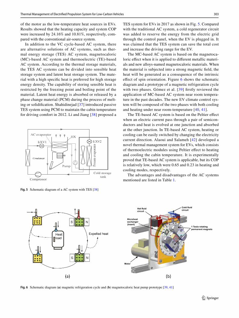
In addition to the VC cycle-based AC system, there are alternative solutions of AC systems, such as ther-mal energy storage (TES) AC system, magnetocaloric (MC)-based AC system and thermoelectric (TE)-based AC system. According to the thermal storage materials, the TES AC systems can be divided into sensible heat storage system and latent heat storage system. The mate-rial with a high specific heat is preferred for high storage energy density. The capability of storing sensible heat is restricted by the freezing point and boiling point of the material. Latent heat energy is absorbed or released by a phase change material (PCM) during the process of melt-ing or solidification. Shahidinejad [37] introduced passive TES system using PCM to maintain the cabin temperature for driving comfort in 2012. Li and Jiang [38] proposed a
TES system for EVs in 2017 as shown in Fig. 5. Compared with the traditional AC system, a cold regenerator circuit was added to reserve the energy from the electric grid through the control panel, when the EV is plugged in. It was claimed that the TES system can save the total cost and increase the driving range for the EV.
The MC-based AC system is based on the magnetoca-loric effect when it is applied to different metallic materi-als and new alloys-named magnetocaloric materials. When the material is subjected into a strong magnetic field, the heat will be generated as a consequence of the intrinsic effect of spin orientation. Figure 6 shows the schematic diagram and a prototype of a magnetic refrigeration cycle with two phases. Gómez et al. [39] firstly reviewed the application of MC-based AC system near room tempera-ture in the past decades. The new EV climate control sys-tem will be composed of the two phases with both cooling and heating under near room-temperature [40, 41].
The TE-based AC system is based on the Peltier effect when an electric current pass through a pair of semicon-ductors and heat is evolved at one junction and absorbed at the other junction. In TE-based AC system, heating or cooling can be easily switched by changing the electricity current direction. Alaoui and Salameh [42] developed a novel thermal management system for EVs, which consists of thermoelectric modules using Peltier effect to heating and cooling the cabin temperature. It is experimentally proved that TE-based AC system is applicable, but its COP is relatively low, which were 0.65 and 0.23 in heating and cooling modes, respectively.
The advantages and disadvantages of the AC systems mentioned are listed in Table 1.
Fig. 5 Schematic diagram of a AC system with TES [38]
Fig. 6 Schematic diagram (a) magnetic refrigeration cycle and (b) magnetocaloric heat pump prototype [39, 41]

304 B. Li et al.
1 3
3 Thermal Management of Electric Vehicles
3.1 Electric Motor in Electrified Powertrain
While the battery performance limits the driving range of an electric vehicle, the motor used to drive the wheels determines the speed and acceleration performance. The latest motor types developed by leading car manufacturers is presented in Table 2, which are mainly categorised into permanent magnet synchronous and induction motors [43]. Permanent magnet is widely used in the rotor of the per-manent magnet synchronous motor for improving overall
efficiency, which could contribute to less heat generation in high-speed application. It can maintain full torque and high efficiency even at very low speed. From this point of view, it is a promising type of motor which is also suitable for compact propulsion system such as in-wheel or hub motor applications [44]. The magnetic losses generally increase with the size of the motor, along with increasing rare metals used in the magnet. Regarding alternating cur-rent induction motor, the technology is relatively mature and independent from critical raw materials such as rare earth and critical metals. The operating mechanism makes it capable to provide high power at high speeds, which is important to achieve higher acceleration performance.
Table 1 Performance comparisons of potential AC systems for EVs
AC system Advantages Disadvantages
Vapour compression refrigeration cycle basedVCR-DH system Simple; reliable; low noise Low heating COP; reduce driving range; alternative
refrigerant issueVC-HP system High capacity density; compact system; relatively
high COPControl strategy; low COP at cold condition; alternative
refrigerant issueNew heat pumping cycle basedTES AC systems Energy efficient; high performance Cumbersome; lower energy densityMC-based AC system Quiet; compact system; no alternative refrigerant
issueLarge magnetic field; poor COP; heat exchangers
required; driving range lossesTE-based AC system Quiet; compact system; easy mode switch; no work-
ing fluid;Less capacity density; lower COP; driving range losses
Table 2 Performance and classification comparison of latest motor developments
Electric vehicle Manufacturer Motor power Motor type Model year
e-Golf SE Volkswagen 100 kW Permanent magnet synchronous 2020i3s edition RoadStyle BMW 135 kW (rear) Alternating current synchronous 2020e-tron Sportback 55 Audi 140 kW (rear); 125 kW (front) Alternating current induction;
Alternating current induction2020
Bolt EV Chevrolet 150 kW (front) Permanent magnet synchronous 2020Twingo Z.E.Zen Renault 60 kW (front) Permanent magnet synchronous 2020Model X Tesla 375 kW (rear); 193 kW (front) Alternating current induction; switched reluctance 2020Model S Tesla 375 kW (rear); 193 kW( front) Alternating current induction; switched reluctance 2020Model 3 Tesla 147 kW (front); 211 kW (rear) Alternating current induction; switched reluctance 2020MG ZS EV MG 105 kW (front) Permanent magnet synchronous 2020EQC 400 Mercedes-Benz Total 300 kW Alternating current induction 2020e-Niro 4 KIA 150 kW (front) Permanent magnet synchronous 2020IONIQ Electric Hyundai 101 kW (front) Permanent magnet synchronous 2020CITIGOe iV SKODA 61 kW (front) Permanent magnet synchronous 2020Corsa-e Opel 100 kW (front) Alternating current synchronous 2020Taycan 4S Porsche 160 kW (front) Permanent magnet synchronous 2020Leaf SL Plus Nissan 160 kW (front) Alternating current synchronous 2019i-pace Jaguar 147 kW (rear); 147 kW (front) Permanent magnet synchronous 2019500e FIAT 83 kW (front) Permanent magnet synchronous 2019

305Thermal Management of Electrified Propulsion System for Low-Carbon Vehicles
1 3
It is not restrained by the proportionate losses with the size of the motor. However, the less flexibility to control the rotation speed and frequency could impose a complex design of controller and inverters [45, 46]. It is an obvious disadvantage considering that the EV typically operates in a wide range of speed.
With determining the specific type of motor being an interesting yet thought-provoking choice for car manufac-turers, the limitation of raw material source and long-term market strategies are the key factors in addition to perfor-mance requirements from consumer ends. A comprehen-sive and sustainable choice will be characterised by proper balance between the economic impacts and performance considerations.
3.2 The Thermal Management of Electric Motors in Electric Vehicles
Regardless of motors used in the coming electric cars, the higher expectation of the EVs needs more powerful elec-tric motors that are able to deliver higher power density, more torque and higher speed and be more compact in size. Those inevitably lead to more parasitic heat loss genera-tion from the electric motor and impose an increasing chal-lenge for thermal management systems [47]. Generally, an electric motor is a very complex thermal system, with dif-ferent materials (copper, resin, steel, magnet, etc.) bringing different temperature limitations [48, 49]. The heat gener-ated in the motor can be identified by Joule losses in wind-ing, mechanical losses in bearings and shaft, iron losses (including hysteretic losses, eddy losses and excess losses) in laminations, and the Joule losses contribute to most of the parasitic heat losses [50]. Such parasitic heat losses must be dissipated efficiently into changing and transient envi-ronment, otherwise unregulated temperature increase will cause the demagnetisation of magnetic or deterioration of the motor efficiency, shorter lifespan or even burnout of the motor windings. In this section, latest thermal management technologies for induction motor and permanent magnet motor are comprehensively reviewed and discussed.
The study on potential methodologies of thermal man-agement technologies can be categorised into experimental testing and theoretical modelling. Due to the high complexi-ties and uncertainties of experimental testing, more theoreti-cal modelling studies are available. The notable modelling methods cover the lumped parameter thermal nodes model and finite element method. In lumped parameter methods, the motor sections divided are lumped into several thermal modes and can be a 2D or 3D model, which could result in less accuracy of hotspots prediction and lack of temperature gradient in each thermal node. On the other hand, the finite element method could help simulate the complete motor
thermally and provide a more detailed temperature contour of each component within the motor, but the analysis usu-ally requires longer computing time and hardware resources.
3.2.1 The Thermal Management of Alternating Current Induction Motor
In low-power-density motor applications, the amount of heat losses is not critical so that traditional air cooling could be adequate. Air cooling including natural and forced convec-tion cooling is capable of keeping the temperature of key components within the safety temperature range. Li et al. [51] studied a fully enclosed air-cooled induction motor used in a small EV. A lumped parameter method was used to pro-pose a steady-state thermal network, and the model is shown in Fig. 7. The results indicated that the temperature of the rotor bar was the highest, followed by the end winding and slot winding in the stator. The influence of axial air cooling path on the rotor was also investigated in this work. In this new cooling topology, the temperature of rotor significantly decreased and the highest temperature point was in the end winding. Ahmed et al. [52] proposed another lumped param-eter method to study the transient temperature response for fully enclosed air-cooled induction motor. The simulation coincided well with the experimental results.
Research using the finite element methods to compre-hensively study the temperature field of the motor were also reported. Moon et al. [53] numerically investigated the ther-mal flow of an air-cooled induction motor by finite element method. The geometric parameters of the fins, such as the height, thickness and pitch of the frame, were studied. It was concluded that the height of fins has no apparent attribution to the heat transfer, the pitch of fin was very sensitive to the rise of winding temperature, and it was suggested that the dense finned frame design was a desirable one. Kim et al. [54] reported a 3D computational electromagnetic coupled model to analyse the effect of auxiliary air-gap fans to cool
Fig. 7 The lumped parameter model for the induction motor [51]

306 B. Li et al.
1 3
a large-capacity, high-speed induction motor. As shown in Fig. 8, with the forced convection flow by air-gap fans, the stagnant air at both ends of air gap could be activated and enhance the air flow in the enclosure. The heat transfer coef-ficients at the winding surface and air gap were improved by 31% and 90%, respectively.
When it comes to high-performance induction motors, the current air cooling method is inadequate to dissipate the heat from hotspots through convection channels. In these cases, the liquid cooling such as water cooling, water/glycol cooling and oil cooling is recommended. Undoubtedly, the structure of the flow channel has a great impact on the cool-ing performance.
Song et al. [55] developed a 3D finite element model to simulate the temperature distribution of an induced motor cooled by a water jacket in steady and transient operating conditions.
The heat losses include the iron loss of stator yoke and teeth and copper losses of the stator winding and rotor
winding which are quantified by electromagnetic analysis. The steady analysis indicated that the highest temperature and lowest temperature of the motor appeared at the bot-tom of the rotor slot and the housing, respectively. When it came to transient conditions, the end winding temperature was lower than the centre winding at the beginning 3–5 min. After that, the temperature of the end winding exceeded the centre wingding gradually.
Ranjan et al. [56] presented a parametric finite element thermal modelling for a high-power-density induction motor and also tested the jacket cooling with water/glycol solution as the coolant. The safety temperature was set to 130 °C as the target motor used some additives. It was found that the achievable current density of winding was 14.6 A/mm2 and 17.8 A/mm2 when the inlet temperatures of coolant were 65 °C and 35 °C, respectively. The experimental investiga-tion was also conducted to in-situ test on the performance of the liquid cooling method. Herbst et al. [57] designed a cooling loop with 50%/50% water–glycol for the thermal
Fig. 8 The temperature distribution of motor [54] a without air-gap fan; b with air-gap fan
Fig. 9 Liquid cooling of induction motor a water jacket cooling [57] and b oil cooling [58]

307Thermal Management of Electrified Propulsion System for Low-Carbon Vehicles
1 3
management of a 100 kW level induction motors. As shown in Fig. 9a, the fluid split into two, followed separate serpen-tine axial passages and joined again at the outlet. When the capacity and the inlet temperature of the cooling fluid were 50 kW and 65 °C, the maximum temperature of the stator predicted was 121.5 °C, which was well below the tempera-ture limit. Assaad et al. [58] proposed an oil-cooled induc-tion motor, whose shaft was hollow functioning as the oil passage and with small holes on its surface. Through these small holes, the oil were projected to the stator end winding and bearings as shown in Fig. 9b. The experimental results indicated that the continuous power of the motor with the oil cooling almost doubled at flow rate 3 L/min and rotation speed 5000 rpm, respectively. It was also suggested that the selection of oil play an important role in determining the losses.
Generally, there are natural convection cooling, forced convection cooling, water jacket cooling and oil jet cool-ing technologies developed for the thermal management of alternating current induction motor. They are mainly used to cool the stator winding. However, with the increase in the motor capacity, the corresponding heat loss from rotor should be completely investigated. As the rotor speed tends to increase for the high-capacity induction motor, the cool-ing of the rotor is not always straightforward by means of conventional cooling techniques, but it will help to achieve more powerful induction motors.
3.2.2 The Thermal Management of Permanent Magnet Motor
As aforementioned, the current thermal management tech-nologies mainly aim to tackle heat from stator winding rather than the rotor. Therefore, the cooling technologies used in the induction motor can also be deployed for the permanent magnet motor without much modification. The cooling of the permanent magnet motor also varies with the heat flux of the motor [59].
In permanent magnet motor applications, liquid cooling prevails due to their excellent heat dissipation ability. Lee et al. [60] developed an optimum flow path to cool both the rotor and stator for a permanent magnet motor, and the structure is shown in Fig. 10. The results indicated that the new cooling method effectively decreased the temperature of the motor. The temperature of the winding decreased by about 50% and 38% compared with cooling by air and water jacket only, respectively. Rocca et al. [61] presented research on thermal management of high-speed permanent magnet motor with oil cooling. A banding sleeve was used to avoid overly big windage in the air gap. Both the lumped param-eter and CFD model were used to analyse the temperature field in the motor. It was found that the cooling strategy
performed well and the predicted results showed good agree-ment with experimental data.
To increase the heat dissipation ability of the cooling methods, some hybrid cooling methods were proposed. Li et al. [62] tested the cooling performance of both water jacket and oil jet cooling. The oil was ejected to the end winding through the nozzles embedded into the end cover, and the structure is shown in Fig. 10. The experimental results indicated a noticeable decrease in the motor tempera-ture, especially for the end winding where the temperature dropped by 20%. Furthermore, with the hybrid cooling, the temperature response was quicker than one only with water jacket cooling. Polikarpova et al. [63] proposed a hybrid cooling method for an axial flux permanent magnet motor. The hybrid cooling method consisted of water jacket cooling in the frame, copper bars in the teeth and potting material in the end winding. It was found that the hybrid system out-performed the water jacket only, and the temperature of the stator winding dropped by 25–35 °C.
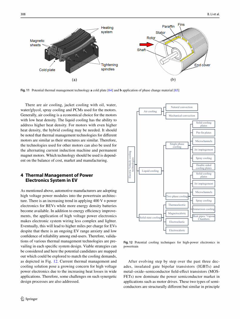
In Fig. 11, apart from that, some potential cooling or ther-mal management technologies were also discussed and pro-vided valuable references for the future commercial appli-cations [64]. Wang et al. [65] introduced the evaporative cooling concept to the thermal management of permanent magnet motor combined with existing water jacket cooling. The cooling mechanism of the motor was discussed, but there were no results revealed. Zhang et al. [66] experimen-tally studied the temperature profile of permanent magnet motors with phase change material in both continuous and intermitted operation conditions. It was found that the latent heat of the material prolonged the heat durability of the motor by up to 50%. In the intermitted operation condition, the temperature profile was flatter and the peak temperature declined in given conditions. In another similar research, Wang et al. [67] claimed the using of phase change material operated well in extending the safety time duration.
Fig. 10 The cooling structure of oil loop [60]
308 B. Li et al.
1 3
There are air cooling, jacket cooling with oil, water, water/glycol, spray cooling and PCMs used for the motors. Generally, air cooling is a economical choice for the motors with low heat density. The liquid cooling has the ability to address higher heat density. For motors with even higher heat density, the hybrid cooling may be needed. It should be noted that thermal management technologies for different motors are similar as their structures are similar. Therefore, the technologies used for other motors can also be used for the alternating current induction machine and permanent magnet motors. Which technology should be used is depend-ent on the balance of cost, market and manufacturing.
4 Thermal Management of Power Electronics System in EV
As mentioned above, automotive manufacturers are adopting high voltage power modules into the powertrain architec-ture. There is an increasing trend in applying 400 V + power electronics for BEVs while more energy density batteries become available. In addition to energy efficiency improve-ments, the application of high voltage power electronics makes electronic system wiring less complex and lighter. Eventually, this will lead to higher miles per charge for EVs despite that there is an ongoing EV range anxiety and low confidence of reliability among end-users. Therefore, valida-tions of various thermal management technologies are pre-vailing in each specific system design. Viable strategies can be considered and here the potential candidates are mapped out which could be explored to match the cooling demands, as depicted in Fig. 12. Current thermal management and cooling solution pose a growing concern for high voltage power electronics due to the increasing heat losses in wide applications. Therefore, some challenges on such synergetic design processes are also addressed.
After evolving step by step over the past three dec-ades, insulated gate bipolar transistors (IGBTs) and metal–oxide–semiconductor field-effect transistors (MOS-FETs) now dominate the power semiconductor market in applications such as motor drives. These two types of semi-conductors are structurally different but similar in principle
Fig. 11 Potential thermal management technology a cold plate [64] and b application of phase change material [65]
Ele
ctri
c V
ehic
le c
oo
lin
g
tech
no
log
ies
Air cooling
Natural convection
Mechanical convection
Liquid cooling
Single phase cooling
Solid cooling plates
Pin-fin plates
Microchannels
Jet impingement
Spray cooling
Double sided cooling plates
Two phase cooling
Solid cooling plates
Jet impingement
Microchannels
Spray cooling
Immersion cooling
Heat pipes/ Vapour Chambers
Solid state cooling
Thermoelectric
Magnetocaloric
Electroelastic
Electrocaloric
Fig. 12 Potential cooling techniques for high-power electronics in powertrain

309Thermal Management of Electrified Propulsion System for Low-Carbon Vehicles
1 3
of diverting the current flow from gate driver. Working as current and voltage regulating and switching devices, the subsystem contains lot of components such as dies, discrete devices, DC link capacitors, laminated busbar, switching drivers, voltage protectors, sensors for voltage, current and temperature. Nevertheless, both semiconductor power losses are dissipated in the form of heat, which must be transferred away from the switching junction effectively, otherwise the rising temperature will limit the performance and long-term reliability of some key components such as dies, intercon-nectors and solders. The heat generated from dies is highly dependent on the layouts design. Thermal limit of each com-ponent is a key factor that indicates the quality of whole module packaging process.
Mainly, the heat losses can be divided into two categories: (1) conduction losses—voltage drop across the IGBTs or MOSFETs depending on the conducted current; (2) switch-ing losses—on and off stages of the modules depending on the current, duty cycle, switching voltage and switching frequency. In some MOSFETs, only electrons flow during forward conduction without minority carriers. Therefore, switching frequency of MOSFETs is only limited by the applied charges and the capacitances itself. This means it could be applied under higher switching frequency with less parasitic heat losses. On the other hand, IGBTs could achieve higher current density and capability than MOS-FETs, and it could achieve much lower on-state voltage decrease. So the balance in trade-offs between switching and conduction losses needs to be carefully evaluated when selecting the proper products to match specific performance requests such as family cars or roadsters in different niche markets.
4.1 Power Module Cooling Challenges: A Power Density Problem
The heat transfer path through source to heat sink is usu-ally evaluated by lumped parameter analysis. There are many 1D, 2D, pesudo-2D and full 3D thermal resistance
models available, following the basic structure as depicted in Fig. 13. Traditionally, the thermal resistance of baseplate from case and heat sink to ambient creates most cause of temperature difference; research focuses on various cooling methods or new materials to enhance the heat transfer in order to minimise the thermal impacts including adopting SiC, AlN, GaN or other advanced wideband gap materi-als. Although not all performance problems are caused by thermally related issues, the whole packaging lifespan will eventually be reflected thermally in real operations such as wiring lift-offs, solder creeping/climbing, layer delamination and cracks due to rapid and frequent thermal shocks [68, 69].
Heat flux in power modules is varied which depended on the duty cycle and real-time switching frequency; it range from below 10 W/cm2 to 1000 W/cm2 in microseconds. As shown in Fig. 14, the heat flux curves also closely link to dif-ferent duty cycles; these variations add more complexity to thermal analysis in design phase. In most designs, the worst-case scenario is usually selected and studied when sizing the thermal management system [70]. In other words, unfortu-nately, the thermal imbalance problem remains unsolved in most cases. It is suggested here that both thermal load and temperature distribution issues should be comprehensively considered. Localised hotspots around junctions should be tackled with appropriate heat spreading techniques, and the abundant thermal layers like baseplate could be removed or integrated into heat sinks. Higher thermal conductivity materials, such as aluminium nitride (AlN) [71], are being explored in order to replace aluminium oxides (Al2O3) ceramic substrates.
4.2 Cutting‑Edge Power Electronic Cooling Solutions
The choices of cold source in the automotive are quite different from other sectors. The parasitic heat loss from vehicle will be dissipated into ambient air ultimately even if energy storage systems are involved. Therefore, cooling
Fig. 13 Conventional air-cooled power module structureFig. 14 Example of heat flux versus switching frequency in different duty cycles for a typical IGBT (Voff = 600 V, Ic = 120 A) [70]
310 B. Li et al.
1 3
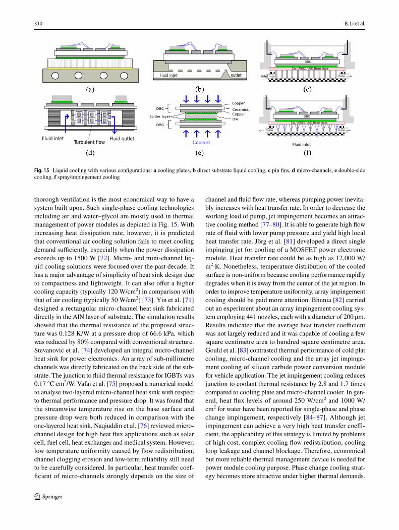
thorough ventilation is the most economical way to have a system built upon. Such single-phase cooling technologies including air and water–glycol are mostly used in thermal management of power modules as depicted in Fig. 15. With increasing heat dissipation rate, however, it is predicted that conventional air cooling solution fails to meet cooling demand sufficiently, especially when the power dissipation exceeds up to 1500 W [72]. Micro- and mini-channel liq-uid cooling solutions were focused over the past decade. It has a major advantage of simplicity of heat sink design due to compactness and lightweight. It can also offer a higher cooling capacity (typically 120 W/cm2) in comparison with that of air cooling (typically 50 W/cm2) [73]. Yin et al. [71] designed a rectangular micro-channel heat sink fabricated directly in the AlN layer of substrate. The simulation results showed that the thermal resistance of the proposed struc-ture was 0.128 K/W at a pressure drop of 66.6 kPa, which was reduced by 80% compared with conventional structure. Stevanovic et al. [74] developed an integral micro-channel heat sink for power electronics. An array of sub-millimetre channels was directly fabricated on the back side of the sub-strate. The junction to fluid thermal resistance for IGBTs was 0.17 °C·cm2/W. Vafai et al. [75] proposed a numerical model to analyse two-layered micro-channel heat sink with respect to thermal performance and pressure drop. It was found that the streamwise temperature rise on the base surface and pressure drop were both reduced in comparison with the one-layered heat sink. Naqiuddin et al. [76] reviewed micro-channel design for high heat flux applications such as solar cell, fuel cell, heat exchanger and medical system. However, low temperature uniformity caused by flow redistribution, channel clogging erosion and low-term reliability still need to be carefully considered. In particular, heat transfer coef-ficient of micro-channels strongly depends on the size of
channel and fluid flow rate, whereas pumping power inevita-bly increases with heat transfer rate. In order to decrease the working load of pump, jet impingement becomes an attrac-tive cooling method [77–80]. It is able to generate high flow rate of fluid with lower pump pressure and yield high local heat transfer rate. Jörg et al. [81] developed a direct single impinging jet for cooling of a MOSFET power electronic module. Heat transfer rate could be as high as 12,000 W/m2·K. Nonetheless, temperature distribution of the cooled surface is non-uniform because cooling performance rapidly degrades when it is away from the center of the jet region. In order to improve temperature uniformity, array impingement cooling should be paid more attention. Bhunia [82] carried out an experiment about an array impingement cooling sys-tem employing 441 nozzles, each with a diameter of 200 µm. Results indicated that the average heat transfer coefficient was not largely reduced and it was capable of cooling a few square centimetre area to hundred square centimetre area. Gould et al. [83] contrasted thermal performance of cold plat cooling, micro-channel cooling and the array jet impinge-ment cooling of silicon carbide power conversion module for vehicle application. The jet impingement cooling reduces junction to coolant thermal resistance by 2.8 and 1.7 times compared to cooling plate and micro-channel cooler. In gen-eral, heat flux levels of around 250 W/cm2 and 1000 W/cm2 for water have been reported for single-phase and phase change impingement, respectively [84–87]. Although jet impingement can achieve a very high heat transfer coeffi-cient, the applicability of this strategy is limited by problems of high cost, complex cooling flow redistribution, cooling loop leakage and channel blockage. Therefore, economical but more reliable thermal management device is needed for power module cooling purpose. Phase change cooling strat-egy becomes more attractive under higher thermal demands.
Fig. 15 Liquid cooling with various configurations: a cooling plates, b direct substrate liquid cooling, c pin fins, d micro-channels, e double-side cooling, f spray/impingement cooling
311Thermal Management of Electrified Propulsion System for Low-Carbon Vehicles
1 3
Nonneman et al. [88] applied a model-based study on differ-ent cooling performance of power modules that integrated phase changing cooling which could match with such power density problem. Hou et al. [89] introduced an open-loop two-phase system for high heat flux electronics experimen-tally which can dissipate over 380 W/cm2 while keeping chip temperature at 90 °C.
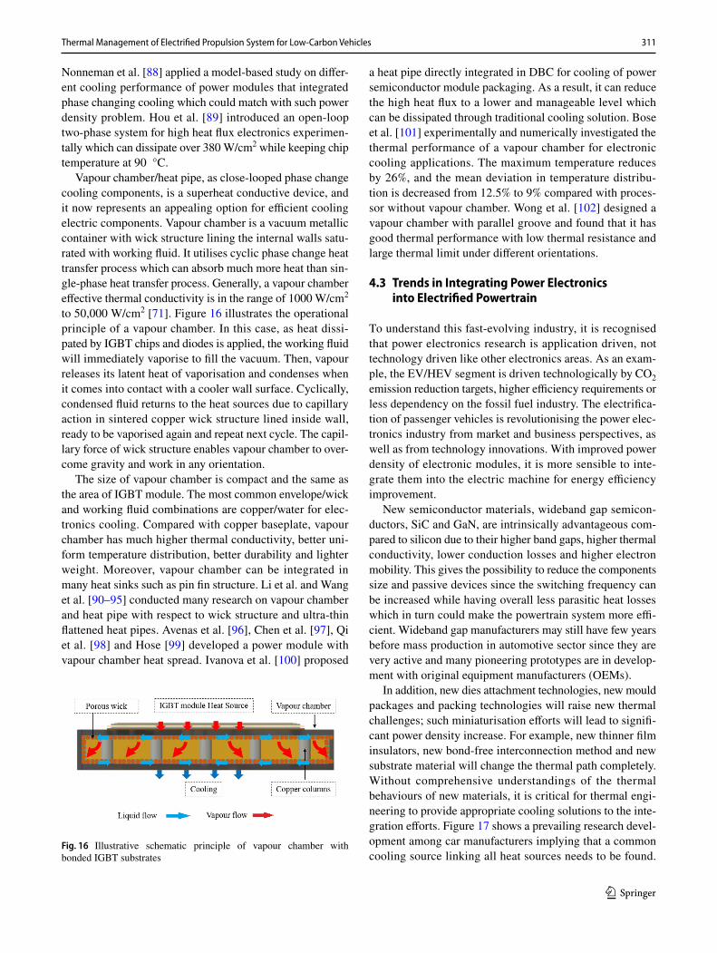
Vapour chamber/heat pipe, as close-looped phase change cooling components, is a superheat conductive device, and it now represents an appealing option for efficient cooling electric components. Vapour chamber is a vacuum metallic container with wick structure lining the internal walls satu-rated with working fluid. It utilises cyclic phase change heat transfer process which can absorb much more heat than sin-gle-phase heat transfer process. Generally, a vapour chamber effective thermal conductivity is in the range of 1000 W/cm2 to 50,000 W/cm2 [71]. Figure 16 illustrates the operational principle of a vapour chamber. In this case, as heat dissi-pated by IGBT chips and diodes is applied, the working fluid will immediately vaporise to fill the vacuum. Then, vapour releases its latent heat of vaporisation and condenses when it comes into contact with a cooler wall surface. Cyclically, condensed fluid returns to the heat sources due to capillary action in sintered copper wick structure lined inside wall, ready to be vaporised again and repeat next cycle. The capil-lary force of wick structure enables vapour chamber to over-come gravity and work in any orientation.
The size of vapour chamber is compact and the same as the area of IGBT module. The most common envelope/wick and working fluid combinations are copper/water for elec-tronics cooling. Compared with copper baseplate, vapour chamber has much higher thermal conductivity, better uni-form temperature distribution, better durability and lighter weight. Moreover, vapour chamber can be integrated in many heat sinks such as pin fin structure. Li et al. and Wang et al. [90–95] conducted many research on vapour chamber and heat pipe with respect to wick structure and ultra-thin flattened heat pipes. Avenas et al. [96], Chen et al. [97], Qi et al. [98] and Hose [99] developed a power module with vapour chamber heat spread. Ivanova et al. [100] proposed
a heat pipe directly integrated in DBC for cooling of power semiconductor module packaging. As a result, it can reduce the high heat flux to a lower and manageable level which can be dissipated through traditional cooling solution. Bose et al. [101] experimentally and numerically investigated the thermal performance of a vapour chamber for electronic cooling applications. The maximum temperature reduces by 26%, and the mean deviation in temperature distribu-tion is decreased from 12.5% to 9% compared with proces-sor without vapour chamber. Wong et al. [102] designed a vapour chamber with parallel groove and found that it has good thermal performance with low thermal resistance and large thermal limit under different orientations.
4.3 Trends in Integrating Power Electronics into Electrified Powertrain
To understand this fast-evolving industry, it is recognised that power electronics research is application driven, not technology driven like other electronics areas. As an exam-ple, the EV/HEV segment is driven technologically by CO2 emission reduction targets, higher efficiency requirements or less dependency on the fossil fuel industry. The electrifica-tion of passenger vehicles is revolutionising the power elec-tronics industry from market and business perspectives, as well as from technology innovations. With improved power density of electronic modules, it is more sensible to inte-grate them into the electric machine for energy efficiency improvement.
New semiconductor materials, wideband gap semicon-ductors, SiC and GaN, are intrinsically advantageous com-pared to silicon due to their higher band gaps, higher thermal conductivity, lower conduction losses and higher electron mobility. This gives the possibility to reduce the components size and passive devices since the switching frequency can be increased while having overall less parasitic heat losses which in turn could make the powertrain system more effi-cient. Wideband gap manufacturers may still have few years before mass production in automotive sector since they are very active and many pioneering prototypes are in develop-ment with original equipment manufacturers (OEMs).
In addition, new dies attachment technologies, new mould packages and packing technologies will raise new thermal challenges; such miniaturisation efforts will lead to signifi-cant power density increase. For example, new thinner film insulators, new bond-free interconnection method and new substrate material will change the thermal path completely. Without comprehensive understandings of the thermal behaviours of new materials, it is critical for thermal engi-neering to provide appropriate cooling solutions to the inte-gration efforts. Figure 17 shows a prevailing research devel-opment among car manufacturers implying that a common cooling source linking all heat sources needs to be found.
Fig. 16 Illustrative schematic principle of vapour chamber with bonded IGBT substrates

312 B. Li et al.
1 3
As configured, the cooling fluid, oil, water–glycol or other advanced heat transfer fluid could be considered to extract the heat losses from inverter (high heat flux), motor (high loss) and gearbox (lubrication). In addition, the fluids could be the same from battery cooling. The overall cooling loops could be simplified with lighter pipes, valves and sensors in the HVAC subsystem. Therefore, it is imperative to find a fluid with wider range of operational condition. Working temperature range in different components varies. Batteries provide high-voltage DC with optimal temperature from 15 to 45 °C; junction temperature in dies needs to be constantly below 150 °C for products in current generation. Therefore, coolant temperature could reach the boiling point before entering the casing channels and internal structure in which windings temperature is designed to maintain below 180 °C for continuous operations. When temperature increases over the Curie points, magnetic materials in motor could expe-rience irreversible losses in performance which cannot be repaired by remagnetisation. In some high-speed induction motors, the AC losses could also cause significant tempera-ture increase that leads to performance loss or even haz-ardous consequences. Currently, many heat transfer fluids, such as mineral oil and dielectric lubricants, could perform at higher flashing points. Without the delicate considera-tion of gearbox cooling and lubrication, plentiful fluids are available in the market. However, the stringent lubrication requirement imposes another difficulty on the fluid selection and mechanical design process. Usually, the oil tempera-ture should be below 90 °C, while a warm-up may still be needed in some extreme cold weather. The properties of oil or heat transfer fluids, such as viscosity, should be rationally reviewed at wider temperature range.
Last but not least, the choices of integrating power elec-tronics into electric motors are flexible and depend on the specific performance requests. The evolving configuration, from box-to-box to coaxial, could be achieved in smaller volume but with increased power density and output. It is expected that more prototypes of fully integrated units will emerge in the next few years so that power electronic system could be completely embedded into the motor casing and sharing cooling loops become a realistic thermal manage-ment approach [103, 104].
5 Conclusions
The current advanced techniques of thermal management, which could be applied to facilitate the development of inte-grated electric machine, have been summarised, and as a conclusion, a mechanic–electric–thermal holistic approach is suggested at early design phase. In addition, a brief intro-duction of the emerging novel cooling techniques, such as vapour chamber cooling, is presented; meanwhile, the keys to a successful integration can be concluded as:
1. Thermal management for electrified powertrain plays an important role in extending the driving range for EVs, as well as maintaining the optimal working condition of motor and electronics. A synergetic design process is needed to further achieve highly integrated electrified powertrain system.
2. Some advanced cooling technologies offer hopes for the future HVAC system in electrified powertrain. A high-
Fig. 17 Illustrative schematic of cooling concept of critical components in powertrain

313Thermal Management of Electrified Propulsion System for Low-Carbon Vehicles
1 3
efficiency HVAC system is essential for commercial EVs to meet the requirement of thermal comfort and driving range under different climate challenges.
3. Single-phase or two-phase liquid cooling solutions, such as micro-channel heat sink cooling, spray cooling and jet impingement cooling, can provide very high heat transfer coefficients and low thermal resistance. And heat pipes/vapour chamber cooling solutions provide integrated methods to automotive thermal management system. Experiments and simulations provided support-ive data on the thermal improvement in power electronic device that could be applied into applications.
Also, vehicular system-level cooling strategy should be considered comprehensively and a holistic approach with economic cost analysis is suggested. In near future, the ther-mal management control tends to be centralised into centre console as energy control platform while be more interac-tive with passengers individually. Therefore, the Internet of things, with real-time data processing capacity, could pro-vide more decision-making control strategies to both cabin thermal comforts and powertrain thermal management. Such control strategies will be more intelligent to facilitate such developments and adapt to stringent regulations and climate challenges.
Acknowledgement This project has been supported in the frame of the BIS-Funded Programme 113167 and the Royal Society project 1130182 and European Union project H2020—MSCA—RISE 778104.
Compliance with ethical standards
Conflict of interest On behalf of all the authors, the corresponding au-thor states that there is no conflict of interest.
Open Access This article is licensed under a Creative Commons Attri-bution 4.0 International License, which permits use, sharing, adapta-tion, distribution and reproduction in any medium or format, as long as you give appropriate credit to the original author(s) and the source, provide a link to the Creative Commons licence, and indicate if changes were made. The images or other third party material in this article are included in the article’s Creative Commons licence, unless indicated otherwise in a credit line to the material. If material is not included in the article’s Creative Commons licence and your intended use is not permitted by statutory regulation or exceeds the permitted use, you will need to obtain permission directly from the copyright holder. To view a copy of this licence, visit http://creat iveco mmons .org/licen ses/by/4.0/.
References
1. Park, S.: A comprehensive thermal management system model for hybrid electric vehicles. University of Michigan (2011)
2. Sean, O., Sarah, N., Andy, S., David, L., Erika, N.: Automo-tive thermal management technology. International Council on Clean Transportation (2016)
3. Bennion, K., Thornton, M.: Integrated vehicle thermal man-agement for advanced vehicle propulsion technologies. SAE Technical Papers (2010)
4. Bouvy, C., Baltzer, S., Jeck, P., Gißing, J., Lichius, T., Eck-stein, L.: Holistic vehicle simulation using modelica-an appli-cation on thermal management and operation strategy for electrified vehicles. In: Proceedings of the 9th International MODELICA Conference, pp. 264–270 (2012)
5. Lajunen, A., Yang, Y., Emadi, A.: Recent developments in ther-mal management of electrified powertrains. IEEE Trans. Veh. Technol. 67(12), 11486–11499 (2018)
6. Zhang, T., Gao, C., Gao, Q., Wang, G., Liu, M., Guo, Y., Xiao, C., Yan, Y.Y.: Status and development of electric vehicle integrated thermal management from BTM to HVAC. Appl. Therm. Eng. 88, 398–409 (2015)
7. Tian, Z., Gan, W., Zhang, X., Gu, B., Yang, L.: Investigation on an integrated thermal management system with battery cool-ing and motor waste heat recovery for electric vehicle. Appl. Therm. Eng. 136, 16–27 (2018)
8. Neubauer, J., Wood, E.: Thru-life impacts of driver aggression, climate, cabin thermal management, and battery thermal man-agement on battery electric vehicle utility. J. Power Sources 259, 262–275 (2014)
9. Wang, Q., Jiang, B., Li, B., Yan, Y.: A critical review of ther-mal management models and solutions of lithium-ion batteries for the development of pure electric vehicles. Renew. Sustain. Energy Rev. 64, 106–128 (2016)
10. Tran, D.-D., Vafaeipour, M., El Baghdadi, M., Barrero, R., Van Mierlo, J., Hegazy, O.: Thorough state-of-the-art analysis of electric and hybrid vehicle powertrains: topologies and inte-grated energy management strategies. Renew. Sustain. Energy Rev. 119, 109596 (2020)
11. Lambert, S.M., Mecrow, B.C., Abebe, R., Vakil, G., Johnson, C.M.: Integrated drives for transport-a review of the enabling thermal management technology. In: 2015 IEEE Vehicle Power and Propulsion Conference (VPPC), pp. 1–6. IEEE (2015)
12. Wei, C., Hofman, T., Ilhan Caarls, E., van Iperen, R.: Inte-grated energy and thermal management for electrified power-trains. Energies 12, 2058 (2019)
13. Horrein, L., Bouscayrol, A., Cheng, Y., Dumand, C., Colin, G., Chamaillard, Y.: Influence of the heating system on the fuel con-sumption of a hybrid electric vehicle. Energ. Convers. Manage. 129, 250–261 (2016)
14. Weustenfeld, T.A., Bauer-Kugelmann, W., Menken, J.C., Strasser, K., Köhler, J.: Heat flow rate based thermal manage-ment for electric vehicles using a secondary loop heating and cooling system. In: Proceedings of the Vehicle Thermal Manage-ment Systems Symposium and Exhibition (VTMS), pp. 10–13 (2015)
15. Hamut, H.S., Dincer, I., Naterer, G.F.: Analysis and optimization of hybrid electric vehicle thermal management systems. J. Power Sources 247, 643–654 (2014)
16. Enthaler, A., Weustenfeld, T., Gauterin, F., Koehler, J.: Thermal management consumption and its effect on remaining range esti-mation of electric vehicles. In: 2014 International Conference on Connected Vehicles and Expo (ICCVE), pp. 170–177. IEEE (2014)
17. Bayraktar, I.: Computational simulation methods for vehicle thermal management. Appl. Therm. Eng. 36, 325–329 (2012)
18. Qi, Z.: Advances on air conditioning and heat pump system in electric vehicles—a review. Renew. Sustain. Energy Rev. 38, 754–764 (2014)
19. Zhang, Z., Li, W., Zhang, C., Chen, J.: Climate control loads pre-diction of electric vehicles. Appl. Therm. Eng. 110, 1183–1188 (2017)
314 B. Li et al.
1 3
20. Zhang, Z., Wang, J., Feng, X., Chang, L., Chen, Y., Wang, X.: The solutions to electric vehicle air conditioning systems: a review. Renew. Sustain. Energy Rev. 91, 443–463 (2018)
21. Wang, D., Yu, B., Li, W., Shi, J., Chen, J.: Heating performance evaluation of a CO2 heat pump system for an electrical vehicle at cold ambient temperatures. Appl. Therm. Eng. 142, 656–664 (2018)
22. Suzuki, T., Ishii, K.: Air conditioning system for electric vehicle. SAE Technical Paper (1996)
23. Brodie, B.R., Takano, Y., Gocho, M.: Evaporator with integrated ejector for automotive cabin cooling. SAE Technical Paper (2012)
24. Nemesh, M., Martinchick, M., Ibri, S.: Cabin heating and wind-shield defrosting for extended range electric, pure electric, & plug-in hybrid vehicles. SAE Int. J. Altern. Powertrains 1, 12–18 (2012)
25. Apfelbeck, R., Barthel, F.: Heating comfort and range perfectly combined-heating systems for vehicles with alternative drive system. Prospects and challenges of biofuel-operated water and air heaters. SAE Technical Paper (2013)
26. Cap, C., Hainzlmaier, C.: Layer heater for electric vehicles. ATZ Worldwide 115(6), 16–19 (2013)
27. Shin, Y.H., Ahn, S.K., Kim, S.C.: Performance characteristics of ptc elements for an electric vehicle heating system. Energies 9(10), 813 (2016)
28. Bauml, T., Dvorak, D., Frohner, A., Simic, D.: Simulation and measurement of an energy efficient infrared radiation heating of a full electric vehicle. In: 2014 IEEE Vehicle Power and Propul-sion Conference (VPPC), pp 1–6 (2014)
29. Clodic, D ZE., Mortada, S.: Impacts of heating and cooling on electrified vehicles. In: Proceedings of the 4th European Work-shop—MAC and Vehicle Thermal Systems (2011)
30. Peng, Q., Du, Q.: Progress in heat pump air conditioning systems for electric vehicles—a review. Energies 9(4), 240 (2016)
31. Zhang, Z., Wang, D., Zhang, C., Chen, J.: Electric vehicle range extension strategies based on improved AC system in cold cli-mate—a review. Int. J. Refrig 88, 141–150 (2018)
32. Hosoz, M., Direk, M.: Performance evaluation of an integrated automotive air conditioning and heat pump system. Energy Con-vers. Manag. 47(5), 545–559 (2006)
33. Kim, K.Y., Kim, S.C., Kim, M.S.: Experimental studies on the heating performance of the PTC heater and heat pump combined system in fuel cells and electric vehicles. Int. J. Automot. Tech-nol. 13(6), 971–977 (2012)
34. Li, H.-J., Zhou, G.-H., Li, A.-G., Li, X.-G., Li, Y.-N., Chen, J.: Heat pump air conditioning system for pure electric vehicle at ultra-low temperature. Therm. Sci. 18, 1667–1672 (2014)
35. Zhou, G.-H., Li, H.-J., Liu, L., Zhao, D.-K., Wei, P.-P., Chen, T.: Numerical approach to a low pressure gas-injection scroll compressor. Therm. Sci. 19, 1383–1388 (2015)
36. Qian, C., Gu, B., Tian, Z., Ma, L., Yang, L.: Performance analysis of dual source heat pump in electric vehicles. Appl. Energy 50, 569–574 (2016)
37. Shahidinejad, S., Bibeau, E., Filizadeh, S.: Design and simulation of a thermal management system for plug-in electric vehicles in cold climates. SAE Technical Paper (2012)
38. Li, Z., Jiang, Y.: The schemes of air conditioning system and cooling system in electric vehicle. Shanghai Auto (2017)
39. Gómez, J.R., Garcia, R.F., Catoira, A.D.M., Gómez, M.R.: Magnetocaloric effect: a review of the thermodynamic cycles in magnetic refrigeration. Renew. Sustain. Energy Rev. 17, 74–82 (2013)
40. Muller, C.: New reversible air-conditioning magnetocaloric sys-tem, environmentally friendly and highly energy efficient. SAE Technical Papers (2009)
41. Vasile, C., Muller, C.: Innovative design of a magnetocaloric system. Int. J. Refrig. 29(8), 1318–1326 (2006)
42. Alaoui, C., Salameh, Z.M.: A novel thermal management for electric and hybrid vehicles. IEEE Trans. Veh. Technol. 54(2), 468–476 (2005)
43. Evspecifications. https ://www.evspe cific ation s.com/en/model /e1d17 8
44. Pellegrino, G., Vagati, A., Boazzo, B., et al.: Comparison of induction and pm synchronous motor drives for EV applica-tion including design examples. IEEE. Trans. Ind. Appl. 48(6), 2322–2332 (2012)
45. Jabbour, N., Mademlis, C.: Online parameters estimation and autotuning of a discrete-time model predictive speed controller for induction motor drives. IEEE. Trans. Power. Electr. 34(2), 1548–1559 (2019)
46. Ouhrouche, M., Errouissi, R., Trzynadlowski, A.: A novel pre-dictive direct torque controller for induction motor drives. IEEE. Trans. Ind. Electron. 63(8), 5221–5230 (2016)
47. Cavazzuti, M., Gaspari, G., Pasquale, S.: Thermal management of a formula e electric motor: analysis and optimization. Appl. Therm. Eng. 157, 113733 (2019)
48. Chiu, H., Jang, J., Yan, W.: Thermal performance analysis of a 30 kW switched reluctance motor. Int. J. Heat. Mass. Transf. 114, 145–154 (2017)
49. Saidur, R.: A review on electrical motors energy use and energy savings. Renew. Sust. Energy Rev. 14(3), 877–898 (2010)
50. Staton, D., Popescu, M., Hawkins, D.: Influence of different end region cooling arrangements on end-winding heat transfer coef-ficients in electrical machines. In: Paper Presented at the IEEE Energy Conversion Congress and Exposition, Atlanta, USA (2010)
51. Li, C., St, C., Li, J.: Heat dissipation evaluation and optimization of air cooling induction motor used for mini electric vehicle. In: Paper Presented at the 20th International Conference on Electri-cal Machines and Systems (ICEMS), Sydney, Australia (2017)
52. Ahmed, F., Ghosh, E., Kar, N.: Transient thermal analysis of a copper rotor induction motor using a lumped parameter tempera-ture network model. In: Paper Presented at the IEEE Transpor-tation Electrification Conference and Expo (ITEC), Dearborn, USA (2016)
53. Moon, S., Jung, Y., Kim, K.: Numerical investigation on thermal-flow characteristics of a totally enclosed fan cooled induction motor. In: Paper Presented at the XXII International Conference on Electrical Machines (ICEM), Lausanne, Switzerland (2016)
54. Kim, C., Lee, K., Yook, S.: Effect of air-gap fans on cooling of windings in a large-capacity, high-speed induction motor. Appl. Therm. Eng. 100, 658–667 (2016)
55. Song, L., Li, Z., Gao, Q.: 3D thermal analysis of water cooling induction motor used for HEV. In: Paper Presented at the 2008 International Conference on Electrical Machines and Systems, Wuhan, China (2008)
56. Ranjan, R., Tangudu, J.: Thermal design of high power-density additively- manufactured induction motors. In: Paper Presented at the IEEE Energy Conversion Congress and Exposition (ECCE), Pittsburgh, USA (2014)
57. Herbst, J., Hahne, J., Jordan, H.: Challenges in the design of a 100 kw induction motor for a phev application. In: Paper Pre-sented at the IEEE Vehicle Power and Propulsion Conference, Dearborn, USA (2009)
58. Assaad, B., Mikati, K., Tran, T.: Experimental study of oil cooled induction motor for hybrid and electric vehicles. In: Paper Presented at the XIII International Conference on Electri-cal Machines (ICEM), Alexandroupoli, Greece (2018)
59. Fawzal, A., Cirstea, R., Gyftakis, K.: The fan design impact on the rotor cooling of axial flux permanent magnet machines. In:

315Thermal Management of Electrified Propulsion System for Low-Carbon Vehicles
1 3
Paper Presented at the XXII International Conference on Electri-cal Machines (ICEM), Lausanne, Switzerland (2016)
60. Lee, K., Cha, H., Kim, Y.: Development of an interior permanent magnet motor through rotor cooling for electric vehicles. Appl. Therm. Eng. 95, 348–356 (2016)
61. Rocca, A., Arumugam, P., Pickering, S.: Thermal management of a high speed permanent magnet machine for an aeroengine. In: Paper Presented at the XXII International Conference on Electri-cal Machines (ICEM), Lausanne, Switzerland (2016)
62. Li, Y., Fan, T., Wen, X.: Experimental investigation on heat transfer of directly-oil-cooled permanent magnet motor. In: Paper Presented at the 19th International Conference on Electri-cal Machines and Systems (ICEMS), Chiba, Japan (2016)
63. Polikarpova, M., Ponomarev, P., Lindh, P.: Hybrid cooling method of axial-flux permanent-magnet machines for vehicle applications. IEEE. Trans. Ind. Electron. 62(12), 7382–7390 (2015)
64. Fasquelle, A., Laloy, D.: Water cold plates cooling in a perma-nent magnet synchronous motor. IEEE IEEE. Trans. Ind. Appl. 53(5), 4406–4413 (2017)
65. Wang, S., Li, Y., Li, Y., Wang, J., Xiao, X., Guo, W.: Transient cooling effect analyses for a permanent-magnet synchronous motor with phase-change-material packaging. Appl. Therm. Eng. 109, 251–260 (2016)
66. Zhang, X., Wang, H., Zhang, G.: Temperature characteristics in the stator model of a permanent magnet motor by water-cooling and evaporative cooling. In: Paper Presented at International Conference on Electrical Machines and Systems, Nanjing, China (2005)
67. Wang, J., Li, Y., Wang, S.: Experimental investigation of the thermal control effects of phase change material based packaging strategy for on-board permanent magnet synchronous motors. Energy Convers. Manag. 123, 232–242 (2016)
68. Randoll, R., Wondrak, W., Schletz, A.: Lifetime and manufactur-ability of integrated power electronics. Microelectron. Reliab. 64, 513–518 (2016)
69. Furukawa, Y., Yamauchi S.: 5—Technologies of a cooling device for power semiconductor. In: Woodhead Publishing Series in Electronic and Optical Materials, Wide Bandgap Power Semi-conductor Packaging, Woodhead Publishing, pp. 111–126 (2018)
70. Mertens, R., Chow, L., Sundaram, K.B., Cregger, R.B., Rini, D.P., Turek, L., Saarloos, B.: Spray cooling of IGBT devices. ASME. J. Electron. Packag. 129(3), 316–323 (2017)
71. Yin, S., Tseng, K.J., Zhao J.: Design of AlN-based micro-channel heat sink in direct bond copper for power electronics packaging. Appl. Therm. Eng. 52(1), 120–129 (2013)
72. Kandlikar, S.G., Hayner, C.N.: Liquid cooled cold plates for industrial high-power electronic devices—thermal design and manufacturing considerations. Heat Transf. Eng. 30(12), 918–930 (2019)
73. Wang, P., McCluskey, P., Bar-Cohen, A.: Two-phase liquid cooling for thermal management of IGBT power electronic module. J Electron Packag. 135(2), 021001 (2013)
74. Stevanovic, L.D., Beaupre, R.A. Gowda, A.V., et al.: Integral micro-channel liquid cooling for power electronics. In: Paper Presented at the Twenty-Fifth Annual IEEE Applied Power Electronic Conference and Exposition (APEC), Palm Spring, USA (2010)
75. Vafai, K., Zhu, L.: Analysis of two-layered micro-channel heat sink concept in electronic cooling. Int. J. Heat Mass Transf. 42(12), 2287–2297 (1999)
76. Naqiuddin, N., Saw, M., Yew, F., et al.: Overview of micro-channel design for high heat flux application. Renew. Sust. Energy Rev. 82, 901–914 (2018)
77. Cassou, A., Tounsi, Fradin, J.: Using compact thermal mod-elling for the investigation of a cooling system dysfunction
applied to a power module with double sided cooling. In: Paper Presented at the 26th International Conference Mixed Design of Integrated Circuits and Systems, Rzeszów, Poland (2019)
78. Bostanci, H., Van, B., Saarloos, A., et al.: Spray cooling of power electronics using high temperature coolant and enhanced surface. In: Paper Presented at the IEEE Vehicle Power and Propulsion Conference, Dearborn (2009)
79. Shailesh, J., Ercan, M.: Two-phase jet impingement cooling for high heat flux wide band-gap devices using multi-scale porous surfaces. Appl. Therm. Eng. 110, 10–17 (2017)
80. Pritish, R., Srinath, V., Khai, N.: Impingement-based high per-formance cooling configurations for automotive power convert-ers. Int. J. Heat Mass Transf. 55(4), 834–847 (2012)
81. Jörg, S., Taraborrelli, G., Sarriegui, R., et al.: Direct single impinging jet cooling of a MOSFET power electronic module. IEEE Trans. Power Electr. 33(5), 4224–4237 (2017)
82. Bhunia, A., Chen, C.: On the scalability of liquid microjet array impingement cooling for large area systems. J. Heat Transf. 133(6), 064501 (2011)
83. Gould, S., Cai, Q., Neft, A.: Liquid jet impingement cooling of a silicon carbide power conversion module for vehicle applica-tions. IEEE Trans. Power Electr. 30(6), 2975–2984 (2015)
84. Oliphant, K., Webb, B., McQuay, M.: An experimental com-parison of liquid jet array and spray impingement cooling in the non-boiling regime. Exp. Therm. Fluid Sci. 18(1), 1–10 (1998)
85. Fabbri, M., Jiang, S., Dhir, V.: Experimental investigation of single-phase micro jets impingement cooling for electronic appli-cations. In: Paper Presented at the HT2003 ASME Summer Heat Transfer Conference, Las Vegas, USA (2003)
86. Bhunia, A., Cai, Q., Chen. C.: Liquid impingement and phase change for high power density electronic cooling. In: Paper Presented at the 41st AIAA Aerospace Sciences Meeting and Exhibit, Reno, NV (2003)
87. Ditri, J., Hahn, R., Cadotte, M., et al.: Embedded cooling of high heat flux electronics utilizing distributed microfluidic impinge-ment jets. In: Paper Presented at the International Technical Con-ference and Exhibition on Packaging and Integration of Elec-tronic and Photonic Microsystems, San Francisco, USA (2015)
88. Nonneman, J., T’Jollyn, I., Clarie, N., et al.: Model-based com-parison of thermo-hydraulic performance of various cooling methods for power electronics of electric vehicles. In: Paper Pre-sented at the 17th IEEE Intersociety Conference on Thermal and Thermomechanical Phenomena in Electronic Systems (ITherm), San Diego, USA (2018)
89. Hou, F., Wang, W., Zhang, H., Chen, C., Chen, C., Lin, T., Cao, L., Zhang, G.Q., Ferreira, J.A.: Experimental evaluation of a compact two-phase cooling system for high heat flux electronic packages. Appl. Therm. Eng. 163, 114338 (2019)
90. Li, Y., Li, Z., Chen, C., et al.: Thermal responses of heat pipes with different wick structures under variable centrifugal accelera-tions. Appl. Therm. Eng. 96, 352–363 (2016)
91. Li, Y., Zhou, W., He, J., et al.: Thermal performance of ultra-thin flattened heat pipes with composite wick structure. Appl. Therm. Eng. 102, 487–499 (2016)
92. Li, Y., Li, Z., Zhou, W., et al.: Experimental investigation of vapor chambers with different wick structures at various param-eters. Exp. Therm. Fluid Sci. 77, 132–143 (2016)
93. Li, Y., Chen, S., He, B., et al.: Effects of vacuuming process parameters on the thermal performance of composite heat pipes. Appl. Therm. Eng. 99, 32–41 (2016)
94. Wang, X., Zheng, H.C., Si, M.Q., et al.: Experimental inves-tigation of the influence of surfactant on the heat transfer per-formance of pulsating heat pipe. Int. J. Heat Mass Transf. 83, 586–590 (2015)

316 B. Li et al.
1 3
95. Hua, C., Wang, X., Gao, X., et al.: Experimental research on the start-up characteristics and heat transfer performance of pulsat-ing heat pipes with rectangular channels. Appl. Therm. Eng. 126, 1058–1062 (2017)
96. Avenas, Y., Gillot, C., Bricard, A., et al.: On the use of flat heat pipes as thermal spreaders in power electronics cooling. In: Paper Presented at the 33rd Annual IEEE Power Electronics Specialists Conference. Cairns, Qld, Australia (2002)
97. Chen, Y., Yan Y., Li, B., et al.: Thermal characterization analysis of IGBT power module integrated with a vapour chamber and pin-fin heat sink. In: Paper Presented at the International Exhibi-tion and Conference for Power Electronics, Intelligent Motion, Renewable Energy and Energy Management (2017)
98. Qi, F., Wang, Y., Bob-Manuel, C., et al.: Advanced cooling solu-tions of high power automotive module. In: Paper Presented at the International Exhibition and Conference for Power Electron-ics, Intelligent Motion, Renewable Energy and Energy Manage-ment (2017)
99. Hose, L., Ibitayo, D., et al.: Integrated vapor chamber heat spreader for power module applications. In: Paper Presented at the International Technical Conference and Exhibition on
Packaging and Integration of Electronic and Photonic Microsys-tems. San Francisco, California, USA (2017)
100. Ivanova, M., Avenas, Y., Schaeffer, C., et al.: Heat pipe inte-grated in direct bonded copper (dbc) technology for cooling of power electronics packaging. IEEE Trans. Power Electr. 21(6), 1541–1547 (2006)
101. Bose, R., Ahammed, N., Asirvatham, L.: Thermal performance of a vapor chamber for electronic cooling applications. J. Mech. Sci. Technol. 31(4), 1995–2003 (2017)
102. Wong, S., Hsieh, K., Wu, J., et al.: A novel vapor chamber and its performance. Int. J. Heat Mass Transf. 53(11–12), 2377–2384 (2010)
103. López, I., Ibarra, E., Matallana, A., et al.: Next generation elec-tric drives for HEV/EV propulsion systems: technology, trends and challenges. Renew. Sustain Energy Rev. 114, 0321–0364 (2019)
104. Iradukunda, A., Huitink, D., Luo, F.: A review of advanced ther-mal management solutions and the implications for integration in high-voltage packages. IEEE J. Em Sel. Top. 8(1), 256–271 (2020)
Related Documents