Electricity

Welcome message from author
This document is posted to help you gain knowledge. Please leave a comment to let me know what you think about it! Share it to your friends and learn new things together.
Transcript

Electricity

Electricity
phenomenon associated with stationary or moving electric charges. Electric charge is a fundamental property of matter and is borne by elementary particles. In electricity the particle involved is the electron , which carries a charge designated, by convention, as negative. Thus, the various manifestations of electricity are the result of the accumulation or motion of numbers of electrons.

Thales
In about 600 BC, the Ancient Greeks discovered that rubbing fur on amber (fossilized tree resin) caused an attraction between the two – and so what the Greeks discovered was actually static electricity.

William Gilbert & Thomas Browne
In the year 1600, English physician William Gilbert used the Latin word “electricus” to describe the force that certain substances exert when rubbed against each other. A few years later another English scientist, Thomas Browne, wrote several books and he used the word “electricity” to describe his investigations based on Gilbert’s work.

Benjamin Franklin
In 1752, Ben Franklin conducted his experiment with a kite, a key, and a storm. This simply proved that lightning and tiny electric sparks were the same thing.

Alessandro Volta
Italian physicist Alessandro Volta discovered that particular chemical reactions could produce electricity, and in 1800 he constructed the voltaic pile (an early electric battery) that produced a steady electric current, and so he was the first person to create a steady flow of electrical charge.

Alessandro Volta
Volta also created the first transmission of electricity by linking positively-charged and negatively-charged connectors and driving an electrical charge, or voltage, through them
Michael Faraday
Michael Faraday created the electric dynamo (a crude power generator), which solved the problem of generating electric current in an ongoing and practical way. Faraday’s rather crude invention used a magnet that was moved inside a coil of copper wire, creating a tiny electric current that flowed through the wire.

Thomas Edison & Joseph Swan
Thomas Edison and Joseph Swan who each invented the incandescent filament light bulb in their respective countries in about 1878. Previously, light bulbs had been invented by others, but the incandescent bulb was the first practical bulb that would light for hours on end.

What are the sources of electricity?
• Main electricity• Electric cells• So what’s the difference?
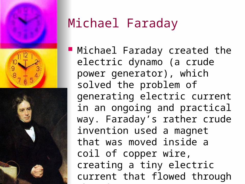
Main Electricity
• Generated by power stations• Delivered to homes and industries
through wires• Finally connected to main sockets• Supplies a lot of electrical energy• Electric shock

Electric Cells
• Used in many portable electrical devices
• Supplies small amount of energy• Safe to touch

Electric Current and Circuit? The rate of flow of electric charges
is called electric current Electric circuit is the path which the
electric current takes

Parts of a Circuit
• Called electrical components• Examples
– Connecting wires– Bulb– Switch– Electric cell

Connecting wires
• Made of two types of materials• Electrical conductor and electrical
insulatorElectrical
conductor – made of
metal such as copper
Electrical insulator – made of plastic

Connecting wires• Symbols of connecting wires• Connecting wires (joined) and
connecting wires (not joined)• See pg 56
Joined Not joined
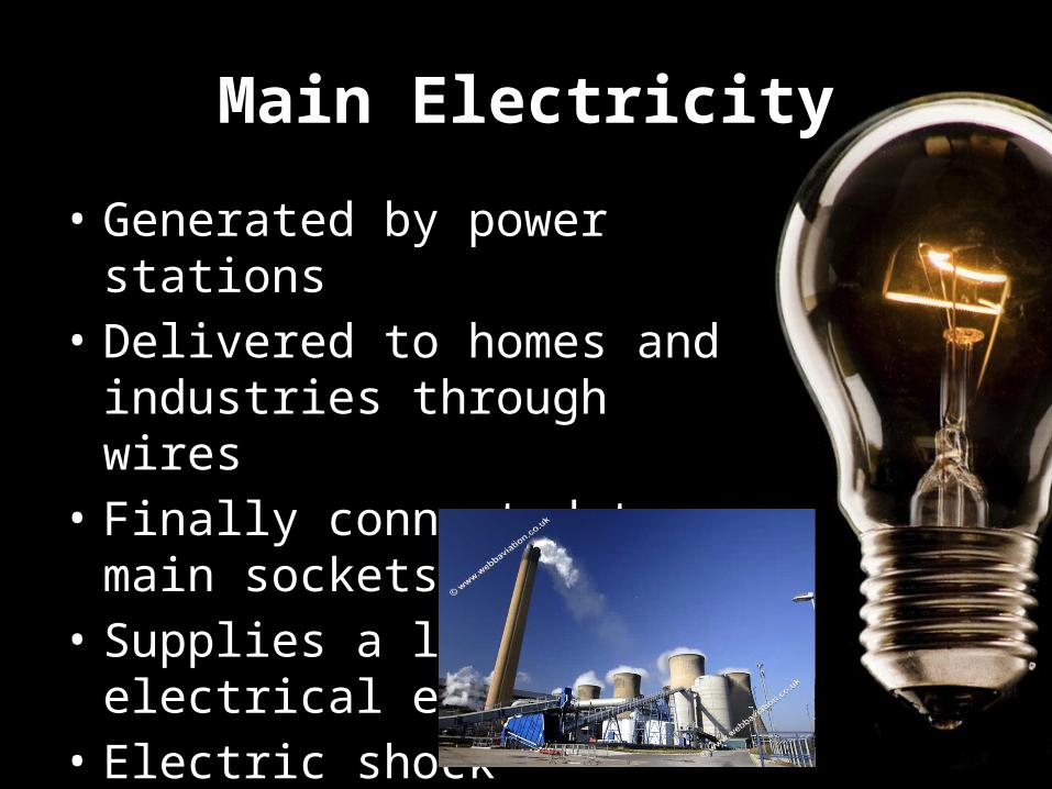
Bulb• Symbol of bulb
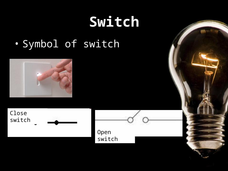
Switch• Symbol of switch
Close switch
Open switch

Electric Cell• Symbol of electric cell
One electric cell
Two electric cell More than two electric cell

Match the following:
joined connecting wires
bulb
closed switch
one electric cell

Complete and incomplete circuits Complete circuits is also
known as closed circuits Incomplete circuits is also
known as opened circuits What is the difference between
the two?

Complete and incomplete circuits Complete circuits is also
known as closed circuits Incomplete circuits is also
known as opened circuits What is the difference between
the two?
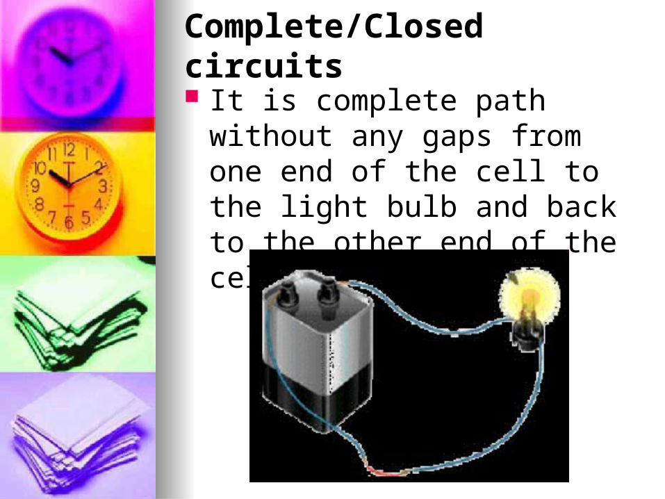
Complete/Closed circuits It is complete path without any
gaps from one end of the cell to the light bulb and back to the other end of the cell

Incomplete/Open circuits The path is incomplete Each circuit has a gap in it and
the bulbs do not light up Example: no source of
electrical energy or connecting wire is missing
See pg 55.

Types of Switches
• A switch is used to open or close a circuit.
• Tap key switch• A plug switch• A mains switch used in buildings• When switch is off, the circuit is
opened and the bulb will not light up• When switch is on, the circuit is closed
and the bulb will light up

Conductors and Insulators

Conductors
• silver• aluminum foil• gold• copper• graphite• steel• brass• bronze

Insulators
• glass• plastic• rubber• porcelein• air• pure water• dry paper• dry wood

Series and Parallel Circuit
Ask and Learn
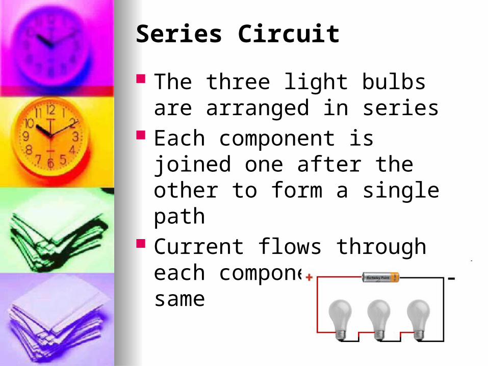
Series Circuit
The three light bulbs are arranged in series
Each component is joined one after the other to form a single path
Current flows through each component is the same

Series Circuit
If one bulb in a series circuit is removed or broken, no current flows
The remaining bulbs do not light up
Because the circuit is opened

Parallel Circuit
Any amount of light bulbs are arranged in parallels
Divides two or more branches and has electrical components in each branch

Parallel Circuit
The current from the battery divides and flows through each branch
If one bulb breaks or removed, other bulbs on the circuit remain lit
Because the circuit remains closed


Formula
The total resistance of two or more resistors connected in series is given by simply adding the individual values of the resistors to find the total sum (RTOT):

Formula
For resistors in parallel: To calculate the total resistance
of a circuit that involves parallel resistors the following formula can be used.
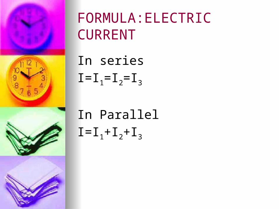
FORMULA:ELECTRIC CURRENT
In series
I=I1=I2=I3
In Parallel
I=I1+I2+I3

FORMULA: VOLTAGE
In Series
V=V1=V2=V3
In Parallel
V=V1+V2+V3

Electric Current

Electric Current
Flow of electric charges This flow of electrons in one
directions in a circuit is called an electric current
Electrons require energy in order to move
Energy come from the electric cell in the circuit
Electric cell has two terminals

Electric Current
Positive and negative Pushes electrons out of the
negative terminal and round the circuit
Flow back to the positive terminal of the cell
Electrons are not used up only energy is used up
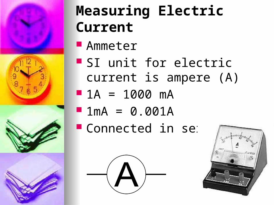
Measuring Electric Current
Ammeter SI unit for electric current is
ampere (A) 1A = 1000 mA 1mA = 0.001A Connected in series

Measuring Electric Current
What is Voltage?
To measure the energy the electrons receive
An electron can have a large amount of potential energy at one point in the circuit
It can also have a low amount of potential energy at another point
The difference in potential energy between the two points is known as voltage
What is Voltage?
SI unit for voltage is volt (V)

Measuring Voltage
Voltmeter

Voltmeter
Connected in parallel across the cell
Has positive (red) terminal and a negative (black) terminal like ammeter
Positive terminal connected to the positive side of the cell
Negative terminal connected to the negative side of the cell

Measuring Voltage
Voltmeter

Different voltage for different electric sources Different electric cell have
different voltage In Singapore the main voltage
is 230V
1.5V9V
12V

How are electric cells connected in electrical appliances? Electric cells are connected in
series with the positive terminal of one cell touching the negative terminal of the next cell
The total voltage across all the electric cells is equal to the sum of the voltages of the individual cells

How are electric cells connected in electrical appliances? For example you have electric
cell of 1.5V If the toy need 9V to work. You will need six 1.5V electric
cells

Resistors
AsknLearn

What is a resistor?
Appliances need to ensure that the correct size of current flows to operate properly
To control the size of the current, electrical components called resistors are used in the circuits

Types of resistors
Fixed Variable

Fixed Resistors
One fixed resistance Resistance can be a fraction of
an ohm to thousands of ohms SI unit is ohms

Variable Resistors
Known as rheostat Vary the resistance in a circuit Resistance change, the current
also changes When resistance decreases,
the current increases

Rheostats
Different types for different purposes
4 factors that affect electric current
Length Area Crossional Area Temperature

Fixed and Variable Resistor
AsknLearn

Arrangement of resistors
ParallelFor resistors in parallel, current
from the electric cell divided among the resistor
More resistors added more electrical charges are able to flow through the resistors at the same time
Current in circuit increasesOverall resistance of the parallel
circuit decreases

Metal with…
Low resistanceCopper and silver
High resistanceNichrome

Resistor – Series and Parallel
AsknLearn

Effects of Electric Current
Heating effect Magnetic effect Chemical effect

Heating Effect
Resistance in circuit wires affects the amount of electric current flowing
Electric current flows through the wire, the wire gets heated up
Electrical energy to heat energy

Heating Effect
Heating element in an electrical appliance consists of high resistance wires such as nichromeVery hotProduce more heat
Connecting wires are made of low resistance materials such as copperLess hotProduce less heat

Heating Effect
If resistance wire gets very hot, light can also be produced
Example: Filament of an electric light bulb

Magnetic Effect
Electric current also produces magnetic effect
Example: placing wire near compass needle and let electric current flow, the needle will move

Magnetic Effect
ElectromagnetCoil of wire usually wound
around a piece of ironWhen current flows, it acts like a
bar magnet If no current flow, the
electromagnet loses its magnetism

Magnetic Effect
ElectromagnetHow to make it stronger?
Increase the current in the coil Increase the number of turns of
wire in the coil Winding the coil around an iron
core

Magnetic Effect
ElectromagnetUses
Magnetic cranes Electric bells Electric motors

Chemical Effect
ElectrolysisUses
Electroplating Extraction of some metals

Formula
The electric current is given by:I= V / R
Corresponding units:ampere (A) = volt (V) / ohm (Ω) This formula is derived from Ohm's law. Where we have:V: voltageI: currentR: resistance

Example Problem
What is the Electric Current if there is 20 volts and 10 ohms
Given:
20 volts-Voltage
10 ohms-Resistance
Unknown:
Electric Current
Solution
I=20volts/10ohms I=2 amperes
Electric Current= 2 amperes

Electroplating

Chemical Effect
Extraction of metalsSolid compound of the metal is
heated until it meltsAn electric current is then
passed through the molten compound
Molten compound break down to give the metal

ADVANTAGES

ADVANTAGES
It is transportable over long distances
It is silent It can be used produce magnetic
fields, which can be used to propel motors
It is very transformable

ADVANTAGES
It is very fast, virtually the speed of light
It can be used to produce other forms of radiant energy, such as radio waves, microwaves, radiant heat and light
EDIT: You can store it for use later

DISADVANTAGES

DISAVANTAGES
It can kill you We become dependent on it We use other dirtier forms of
energy (nuclear, fossil fuels) to produce it
There is growing concern that the magnetic fields around transmission lines may be unhealthy

ELECTRICAL SAFETY

Outlets
Check the Outlets that have loose-fitting plugs which can heat and lead to fire
Replace any missing or broken wall plates
Place the safety covers on all unused outlets that are accessible to children

MAGNET

MAGNET
The black metallic that has the property of contracted iron is called loadstone
The natural force of attractive pieces of iron is called magnetism
Loadstone was later known magnet for the magnetic property

Magnet
Thales was the Greek philosopher who first discovered the magnetic property of loadstone

ELECTROMAGNETISM

Electromagnetism
Relates to the magnetic field generated around a conductor when current is passing through it

Coil
Coil – A number of turns of wire wound around a
core to produce magnetic flux (an electromagnet) or
to react to a changing magnetic flux (an inductor).
Electromagnet – A magnet consisting of a coil
Coil
wound on a soft iron or steel core. When current is
passed through the coil, a magnetic field is generated
and the core is strongly magnetized to concentrate
the magnet field.

Left-hand rule
If the fingers of the left hand are placed around the wire so that the thumb points in the direction of the electronic current flow, the finger will be pointing in the direction of the magnetic field being produced by the conductor

ELECTROMAGNETIC INDUCTION

Electromagnetic induction
The voltage produced in a coil due to relative motion between the coil and magnetic lines of force.
Faraday’s Law – When a magnetic field cuts a conductor, or when a conductor cuts a magnetic field, an electric current will flow in the conductor if a closed path is provided over which the current can circulate.

Electromagnetic induction
Lenz’s Law – The current induced in a circuit due to a change in the magnetic field is so directed as to oppose the change in flux, or to exert a mechanical force opposing the motion.
Weber – A unit of magnetic flux. One weber (10^8 maxwells) is the amount of flux that, when linked with a single turn of wire for an interval of one second, will induce an electromotive force of one volt.


ELECTROMAGNETIC INDUCTION

EINSTEIN
Electricity and magnetism were long thought to be separate forces. It was not until the 19th century that they were finally treated as interrelated phenomena. In 1905 Albert Einstein’s special theory of relativity established beyond a doubt that both are aspects of one common phenomenon.
EINSTEIN
At a practical level, however, electric and magnetic forces behave quite differently and are described by different equations. Electric forces are produced by electric charges either at rest or in motion. Magnetic forces, on the other hand, are produced only by moving charges and act solely on charges in motion.

FARADAY
He discovered in work that forms the basis of electric power generation. Conversely, a changing electric field produces a magnetic field,
Electric phenomena occur even in neutral matter because the forces act on the individual charged constituents
Related Documents