RUS Bulletin 1728F-803 Viewing Instructions There are both bookmarks and links imbedded in this file. Browsing with bookmarks Bookmarks mark parts of a document for quick access. To jump to a topic by using its bookmark: 1. The bookmarks are shown on the left side of the screen. If a triangle appears to the left of the bookmark, click the triangle to show or hide subordinate bookmarks. 2. To go to the destination specified by a bookmark, click the bookmark text or double- click the page icon to the left of the bookmark name. Following links The various indices in this bulletin use links to allow the user to quickly go to the desired drawing. To follow a link: 1. Move the pointer over a linked area. The pointer changes to a pointing finger when positioned over a link. 2. Click to follow the link. General information: You can use the buttons at the top of the screen for going from page to page. Also, by right-clicking your mouse, you will see a navigation box. For details, please see the Acrobat Reader help screens.

Welcome message from author
This document is posted to help you gain knowledge. Please leave a comment to let me know what you think about it! Share it to your friends and learn new things together.
Transcript
RUS Bulletin 1728F-803Viewing Instructions
There are both bookmarks and links imbedded in this file.
Browsing with bookmarks
Bookmarks mark parts of a document for quick access.
To jump to a topic by using its bookmark:
1. The bookmarks are shown on the left side of the screen. If a triangle appears to theleft of the bookmark, click the triangle to show or hide subordinate bookmarks.
2. To go to the destination specified by a bookmark, click the bookmark text or double-click the page icon to the left of the bookmark name.
Following links
The various indices in this bulletin use links to allow the user to quickly go to the desireddrawing.
To follow a link:
1. Move the pointer over a linked area. The pointer changes to a pointing finger whenpositioned over a link.
2. Click to follow the link.
General information:
You can use the buttons at the top of the screen for going from page to page. Also, byright-clicking your mouse, you will see a navigation box. For details, please see theAcrobat Reader help screens.
UNITED STATES DEPARTMENT OF AGRICULTURERural Utilities Service
RUS BULLETIN 1728F-803
SUBJECT: Specifications and Drawings for 24.9/14.4 kV LineConstruction
Incorporated by reference in 7 CFR Part 1728
TO: All RUS BorrowersRUS Electric Staff
EFFECTIVE DATE: Date of Approval
EXPIRATION DATE: Not applicable. Incorporated by reference in 7CFR Part 1728
OFFICE OF PRIMARY INTEREST: Distribution Branch, Electric StaffDivision
FILING INSTRUCTIONS: This bulletin is an update and revision ofprevious REA Bulletin 50-5 (D-803), (revised September, 1969),and has been renumbered and renamed as RUS Bulletin 1728F-803,Specifications and Drawings for 24.9/14.4 kV Line Construction.Replace previous Bulletin 50-5 with this bulletin and file with7 CFR Part 1728.
PURPOSE: The specifications and drawings of this bulletin havebeen published to set forth requirements, specifications andstandards for the construction of 24.9/14.4 kV overhead electricdistribution lines and associated equipment and constructionassembly units.
GENERAL: Listed below are some of the significant changes andadditions which were made during the update of this bulletin:
(a) The bulletin has been reformatted into 19 separatesections or categories. Each section generallycontains construction specifications, an index ofdrawings, and construction drawings of assembliesdesigned to perform a similar function.
(b) New tables have been added to define maximum lineangles and soil classification data. Appendix 2 at theend of the bulletin documents the formula and data usedto determine the line angles in the tables.

BULLETIN 1728F-803: INDEX
SECTION CATEGORY DESCRIPTIONSGeneral Construction SpecificationsConductor Installation Specifications
A SINGLE-PHASE PRIMARY POLE TOP ASSEMBLY UNITSIndex AConstruction Specifications for Pole Top AssembliesTables I - V: Maximum Line AnglesSingle-Phase Primary Pole Top Construction Drawings
B TWO-PHASE PRIMARY POLE TOP ASSEMBLY UNITSIndex BTwo-Phase Primary Pole Top Construction Drawings
C THREE-PHASE PRIMARY POLE TOP ASSEMBLY UNITSIndex CThree-Phase Primary Pole Top Construction Drawings
D DOUBLE-CIRCUIT PRIMARY POLE TOP ASSEMBLY UNITSIndex DDouble-Circuit Primary Pole Top Construction Drawings
E GUYING ASSEMBLY UNITSIndex EConstruction Specifications for GuysGuying Construction Drawings
F ANCHOR ASSEMBLY UNITSIndex FConstruction Specifications for AnchoringTable F: Soil ClassificationsAnchor Construction Drawings
G TRANSFORMER ASSEMBLY UNITSIndex GConstruction Specifications for Taps, Jumpers, and ArrestersTransformer Construction Drawings
H GROUNDING ASSEMBLY UNITSIndex HConstruction Specifications for GroundingGrounding Construction Drawings

BULLETIN 1728F-803: INDEX (Continued)
SECTION CATEGORY DESCRIPTIONS
J SECONDARY ASSEMBLY UNITSIndex JConstruction Specifications for Secondaries and Service DropsSecondary Construction Drawings
K SERVICE ASSEMBLY UNITSIndex KService Construction Drawings
L TYING GUIDESIndex LTying Guide Drawings
M MISCELLANEOUS ASSEMBLY UNITS AND GUIDESIndex MRight-of-Way Clearing SpecificationsMiscellaneous Construction Drawings and Guides
N NEUTRAL ASSEMBLY UNITSIndex NTables VI,VII: Maximum Line AnglesNeutral Construction Drawings
P PROTECTION ASSEMBLY UNITSIndex PProtection Construction Drawings
Q METERING ASSEMBLY UNITSIndex QMetering Construction Drawings
R OIL CIRCUIT RECLOSER ASSEMBLY UNITSIndex ROil Circuit Recloser Construction Drawings
S SECTIONALIZING ASSEMBLY UNITSIndex SSectionalizing Construction Drawings
BULLETIN 1728F-803: INDEX (Continued)
SECTION CATEGORY DESCRIPTIONS
W WOOD POLES, CROSSARMS AND BRACESIndex WConstruction Specifications for Poles and CrossarmsTable W: Pole Setting DepthsPole and Crossarm Guides and Assembly Drawings
Y VOLTAGE ALTERATION EQUIPMENT ASSEMBLY UNITSIndex YVoltage Alteration Equipment Construction Drawings
APPENDICES
1 TABLE OF SELECTED SI TO METRIC CONVERSIONS
2 DERIVATION OF MAXIMUM PERMISSIBLE LINE ANGLES
GENERAL CONSTRUCTION SPECIFICATIONS
All construction work shall be done in a safe, thorough, andworkmanlike manner in accordance with the staking sheets, plansand specifications, and the construction drawings.
The provision of 7 CFR section 1724.50 “Compliance with NationalElectrical Safety Code (NESC)” applies to all borrower electricsystem facilities regardless of the source of financing.
A borrower must ensure that its electric system, including allelectric distribution, transmission, and generating facilities,is designed, constructed, operated, and maintained in accordancewith all applicable provisions of the most current and acceptedcriteria of the National Electrical Safety Code (NESC) and allapplicable and current electrical and safety requirements of anyState or local governmental entity. This requirement applies tothe borrower’s electric system regardless of the source offinancing. Copies of the NESC may be obtained from the Instituteof Electrical and Electronic Engineers, Inc. at the followingaddress:
IEEE Customer Service445 Hoes Lane, PO Box 1331Piscataway, NJ 088555-1331
Any electrical standard requirements established by RUS are inaddition to, and not in substitution for or a modification of,the most current and accepted criteria of the NESC and anyapplicable electrical or safety requirements of any State orlocal governmental entity.
Overhead distribution circuits shall be constructed with not lessthan the Grade C strength requirements as described in section26, Strength Requirements, of the NESC when subjected to theloads specified in NESC Section 25, Loadings for Grades B and C.Overhead transmission circuits shall be constructed with not lessthan the Grade B strength requirements as described in NESCSection 26.
The drawings of equipment and materials used in the constructionassemblies are meant to depict the general categories of itemsfound in RUS Informational Publication 202-1, “List of MaterialsAcceptable for Use on Systems of RUS Electrification Borrowers,”(“List of Materials”). Any drawing of any piece of equipment ormaterial that resembles a specific product of a manufacturer isunintentional.

Materials to be used for construction are designated by one ormore small alphabetic characters shown on the drawings and in the“ITEM” column in the material blocks. The borrower may use anymaterial contained in the “List of Materials” from the categoryof material as designated by the corresponding small letter(s).For example, “b” designates a steel, pole top pin. The borrowermay use, at its discretion, any of the applicable pole top pinsfrom category “b” of the “List of Materials.”
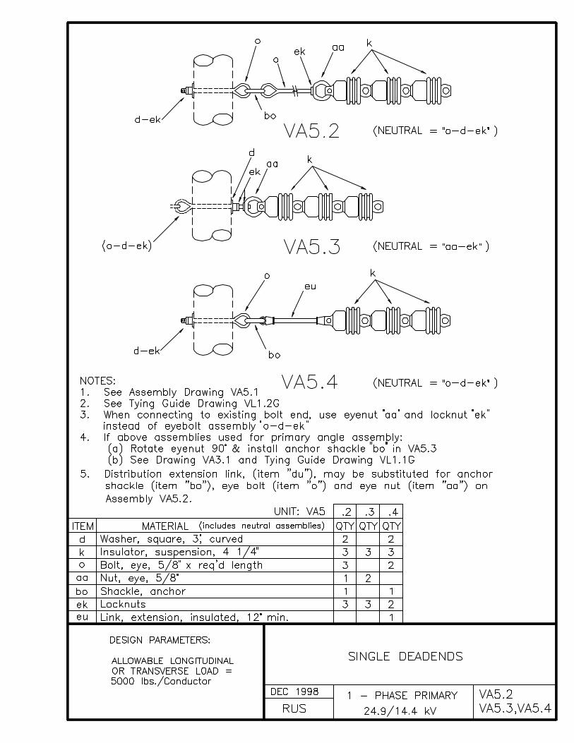
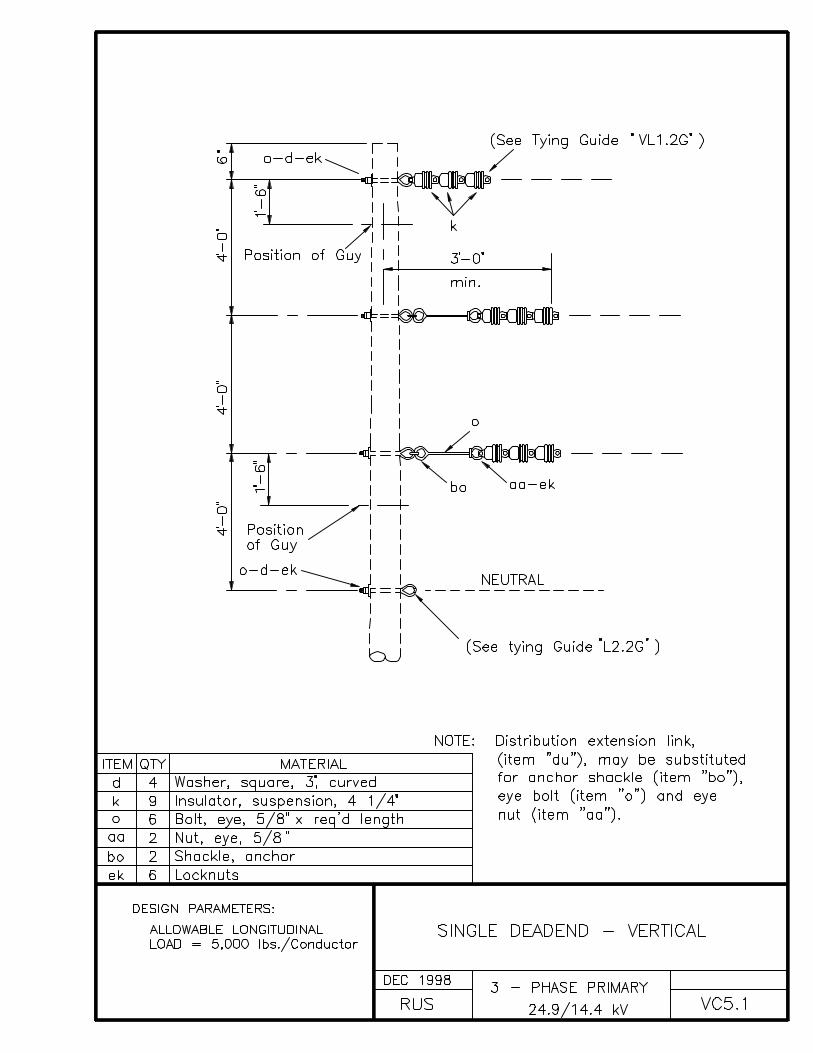
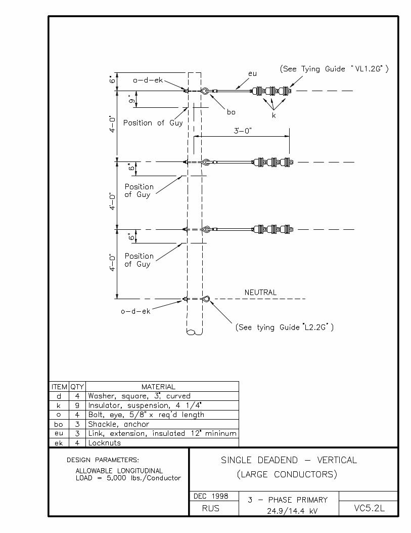
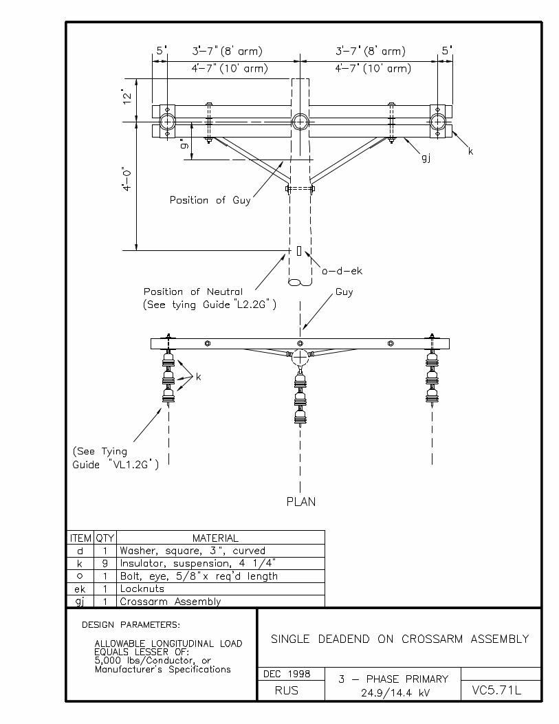
Similarly, the drawings of the bulletin show the use of three,4 1/4 inch, ANSI Class 52-9A suspension insulators for 24.9/14.4kV primary deadends. The borrower may use three, 6 inch, ANSIClass 52-1 or two, 9 inch, ANSI Class 52-4 suspension insulators,or one polymer distribution insulator, all of which are containedin category “k” in the “List of Materials.” In the latter cases,the quantity (“QTY”) of the insulators to be used must bemodified accordingly.
The Federal Aviation Administration (FAA) requires (14 CFR part77) that in cases where structures or conductors will exceed aheight of 200 feet, or are within 20,000 feet of an airport, thenearest regional or area office of the FAA be contacted and FAAForm 7460-1 be filled if necessary.
CONDUCTOR INSTALLATION SPECIFICATIONS
Conductors must be handled with care. Conductors shall neitherbe trampled on nor run over by vehicles. Each reel shall beexamined and the wire inspected for cuts, kinks, or otherinjuries. Injured portions shall be cut out and the conductorspliced. The conductors shall be pulled over suitable rollers orstringing blocks properly mounted on the pole or crossarm ifnecessary to prevent binding while stringing.
Conductors shall be sagged in accordance with the conductormanufacturer's recommendations. All conductors shall be saggedevenly. The air temperature at the time and place of saggingshall be determined by a certified thermometer.
The sag of all conductors after stringing shall be in accordancewith the engineer's instructions.
Conductors shall be spliced and dead-ended as shown on theconstruction drawings. There shall be not more than one spliceper conductor in any span and splices shall be located at least10 feet from the conductor support. No splices shall be locatedin Grade B crossing spans and preferably not in adjacent spans.Splices shall be installed in accordance with the manufacturer'sspecifications and recommendations.
All conductors shall be cleaned thoroughly by wirebrushing beforesplicing or installing connectors or clamps. A suitableinhibitor shall be used before splicing or applying connectorsover aluminum conductor.
Connectors and hot-line clamps suitable for the purpose shall beinstalled as shown on the drawings and also in accordance withthe manufacturer's specifications and recommendations. On allhot-line clamp installations, the clamp and jumper shall beinstalled so that they are permanently bonded to the load side ofthe line, allowing the jumper to be de-energized when the clampis disconnected.
The use of stirrups to connect tap conductors (jumper wires) toprimary conductors may be used if the following criteria are met:
• The stirrup and hot line clamp shall be sized to meet orexceed the current carrying capacity of the tap conductor orequipment jumper;
• All stirrup conductors shall be made of copper or bronze;• All stirrup conductors shall be made of #2 copper equivalent
or larger;
• All-purpose or aluminum hot line clamps shall not be used withstirrups;
• All stirrups, connectors, and clamps shall be installed inaccordance with the manufacturer’s specifications;
• Stirrups with two compression connectors are not to be used inareas of vibrating conductors;
• Stirrups are not to be used to connect main lines or heavilyloaded tap lines.
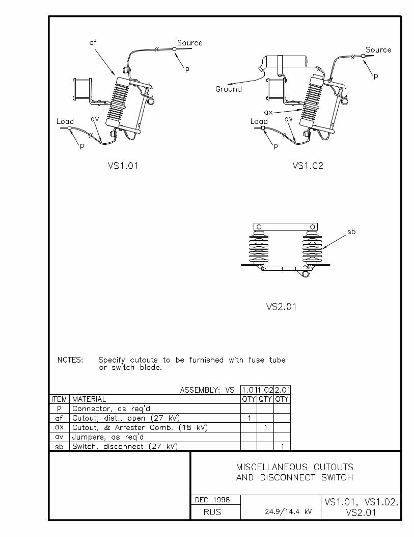
Stirrups are not recommended to be used to connect reclosers,autotransformers, or line regulators. Stirrups and hot lineclamps should not be used for sectionalizing tap and especiallymain lines for operational or maintenance purposes. Permanentcompression or bolted type connectors should be used because oftheir better current carrying capabilities and reliability. Lineswitches, fused cutouts, or solid blade cutouts should be used atline locations where occasional line sectionalizing may berequired.
At locations where permanent connections using compression orbolted type connectors are not desired, and where theinstallation or sectionalizing equipment is also not desired,then the standards specify the installation of hot line clamps(over armor rod on aluminum conductors).
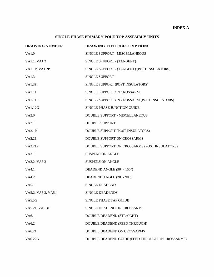
INDEX A
SINGLE-PHASE PRIMARY POLE TOP ASSEMBLY UNITS
DRAWING NUMBER DRAWING TITLE (DESCRIPTION)
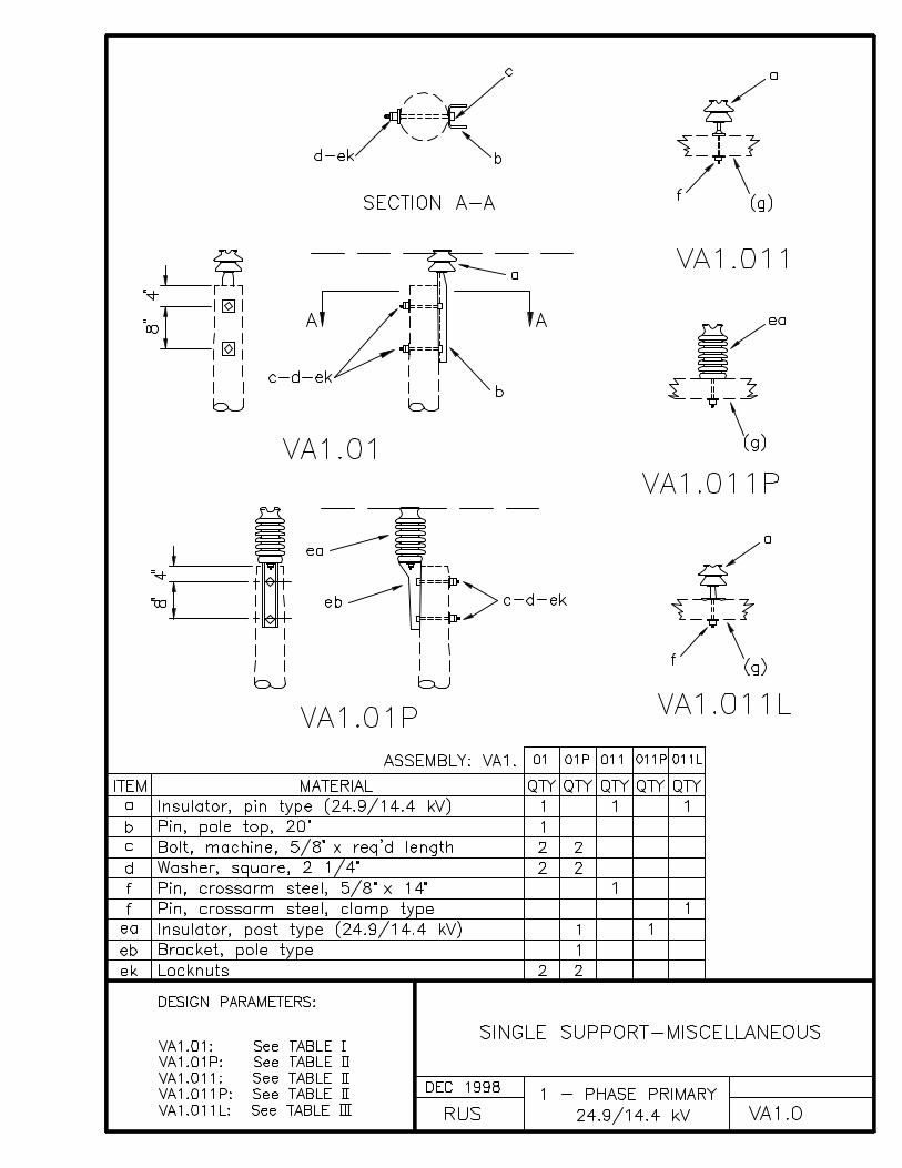
VA1.0 SINGLE SUPPORT - MISCELLANEOUS
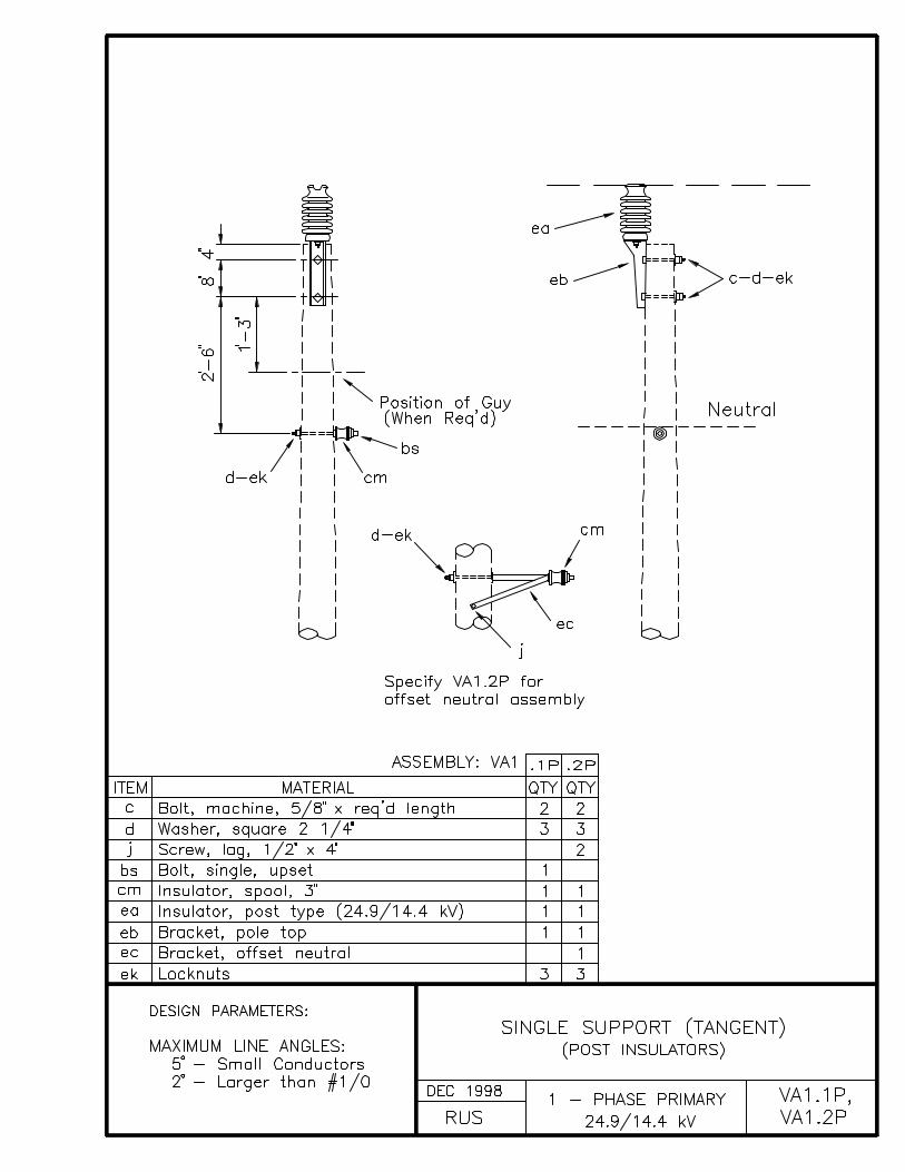
VA1.1, VA1.2 SINGLE SUPPORT - (TANGENT)
VA1.1P, VA1.2P SINGLE SUPPORT - (TANGENT) (POST INSULATORS)
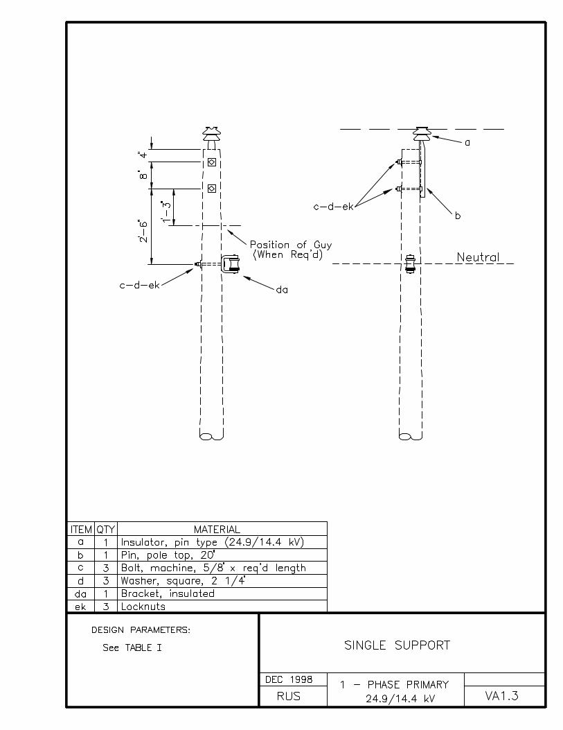
VA1.3 SINGLE SUPPORT
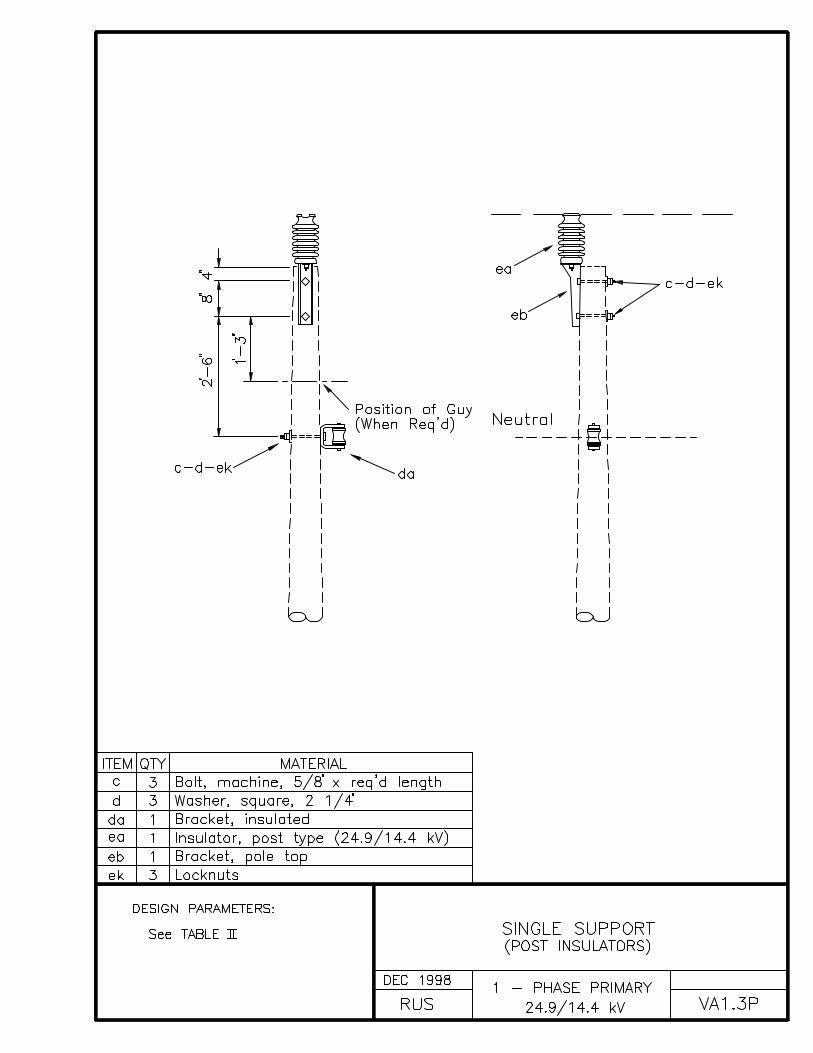
VA1.3P SINGLE SUPPORT (POST INSULATORS)
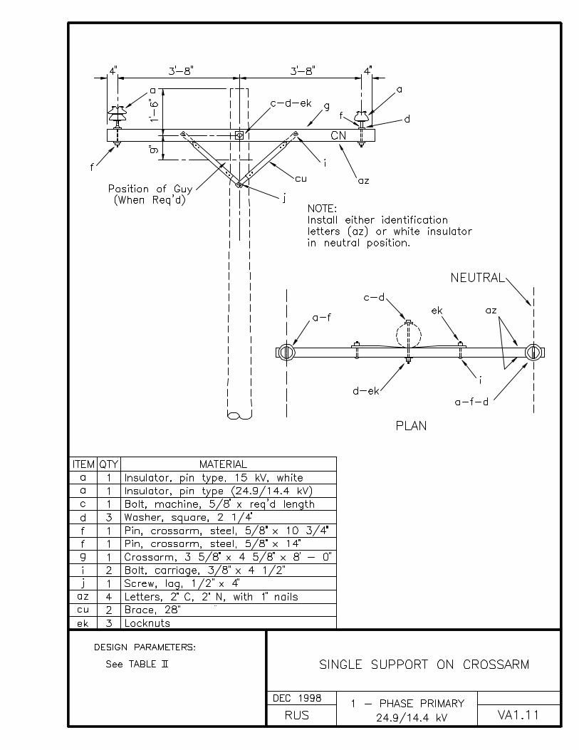
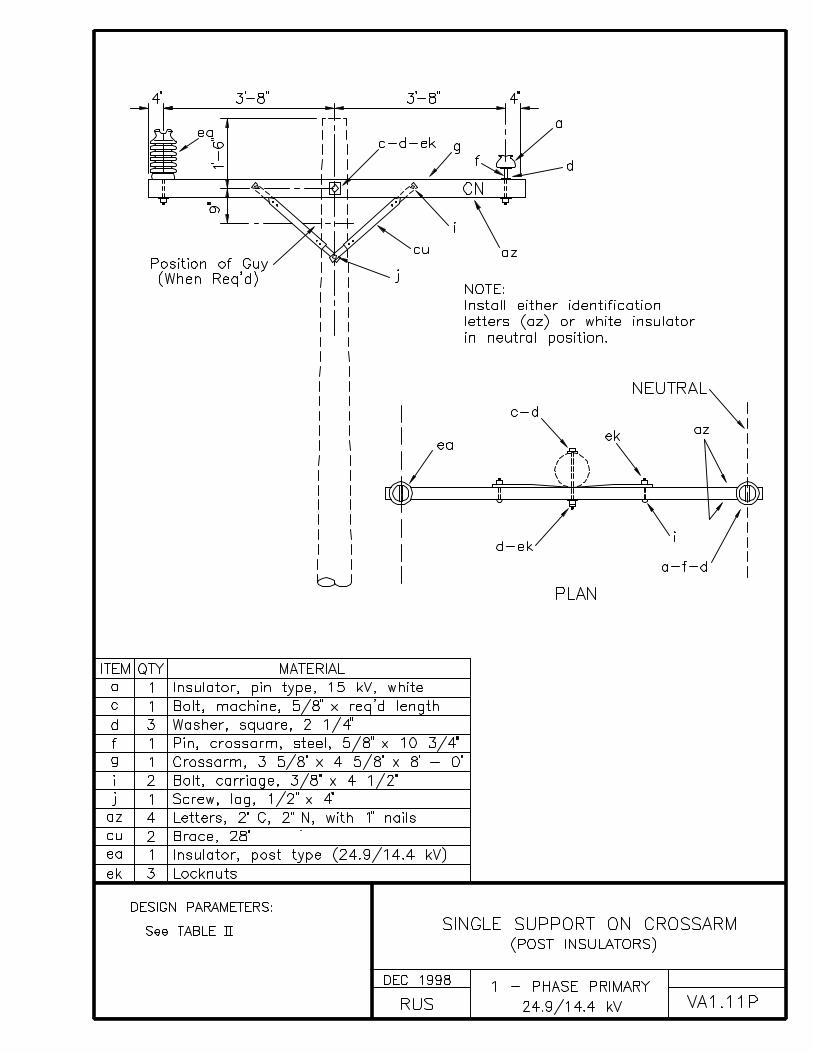
VA1.11 SINGLE SUPPORT ON CROSSARM
VA1.11P SINGLE SUPPORT ON CROSSARM (POST INSULATORS)
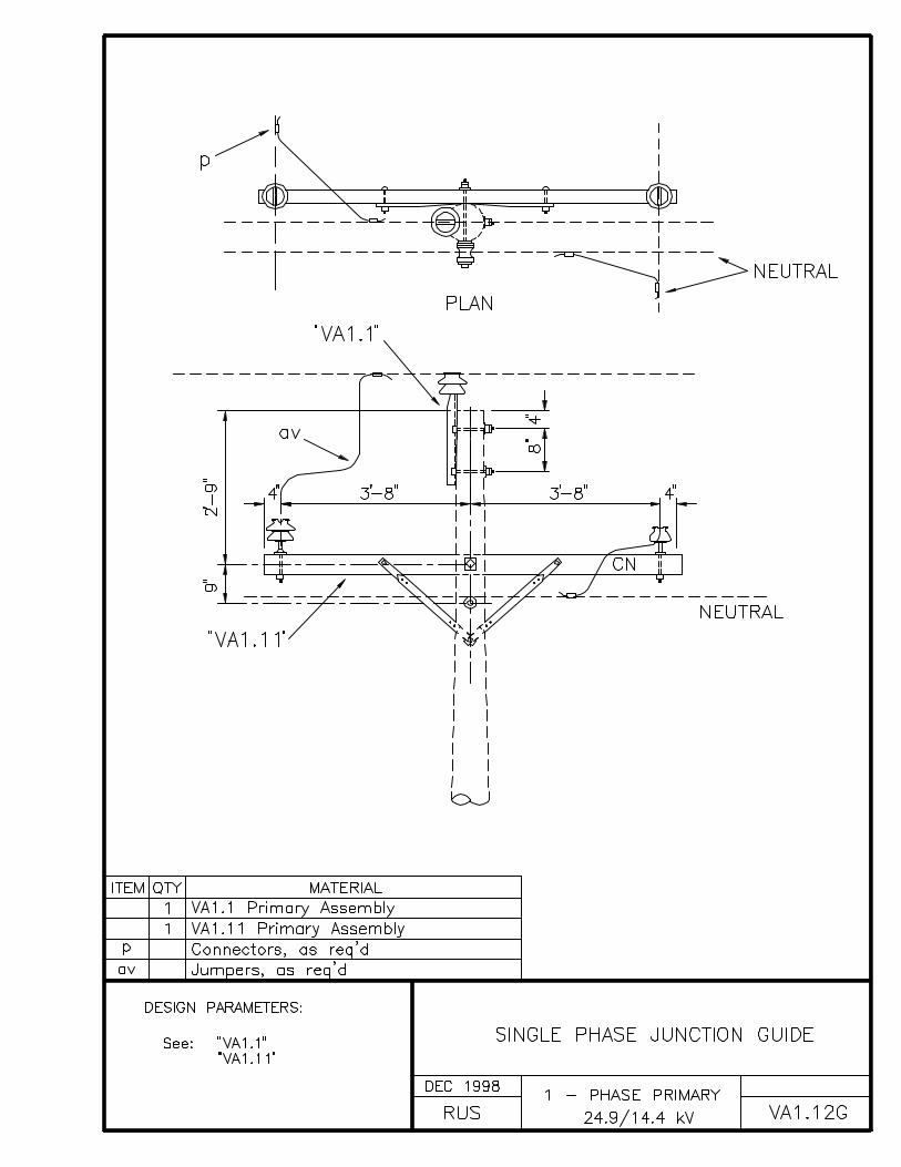
VA1.12G SINGLE PHASE JUNCTION GUIDE
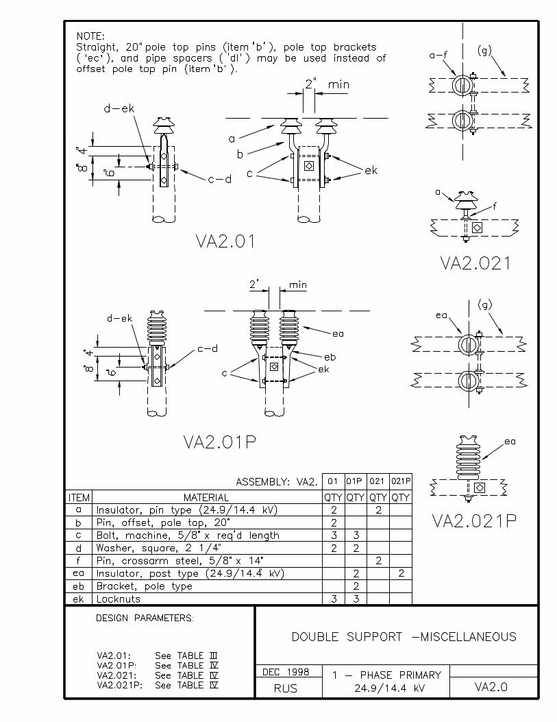
VA2.0 DOUBLE SUPPORT - MISCELLANEOUS
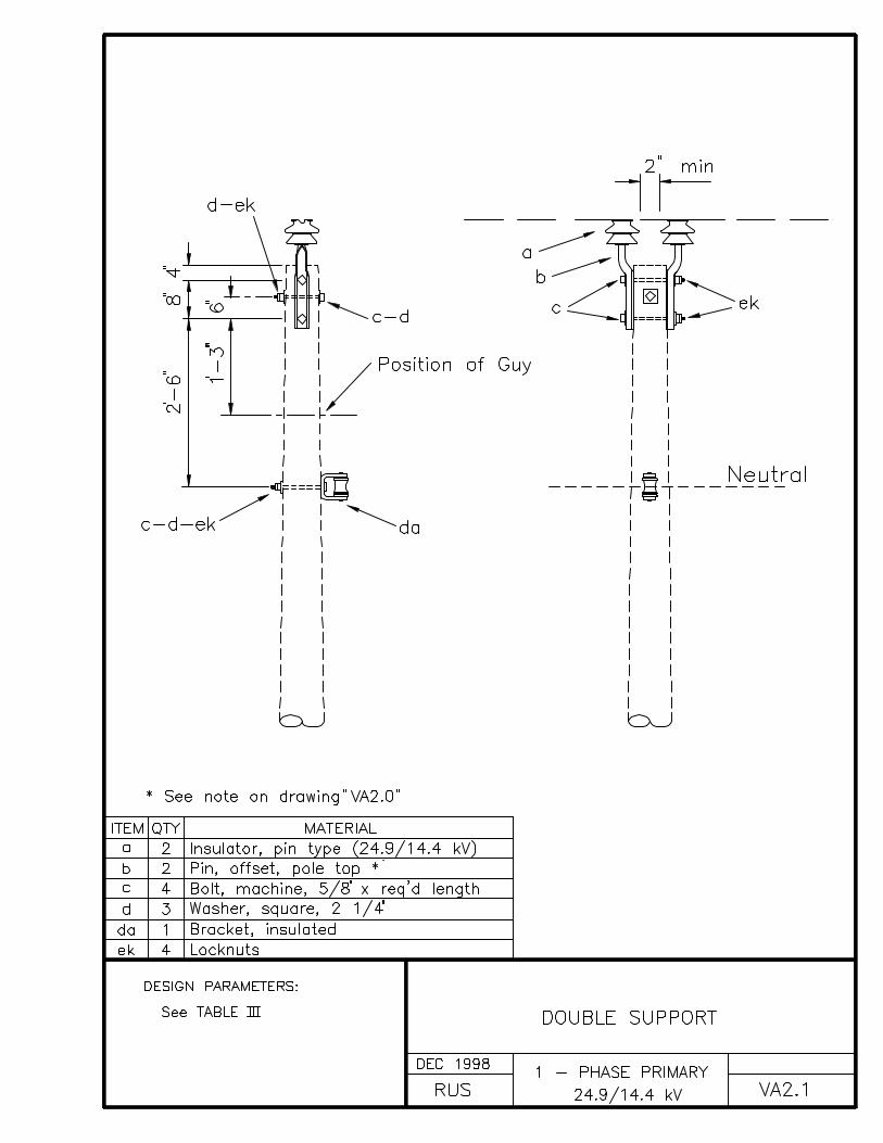
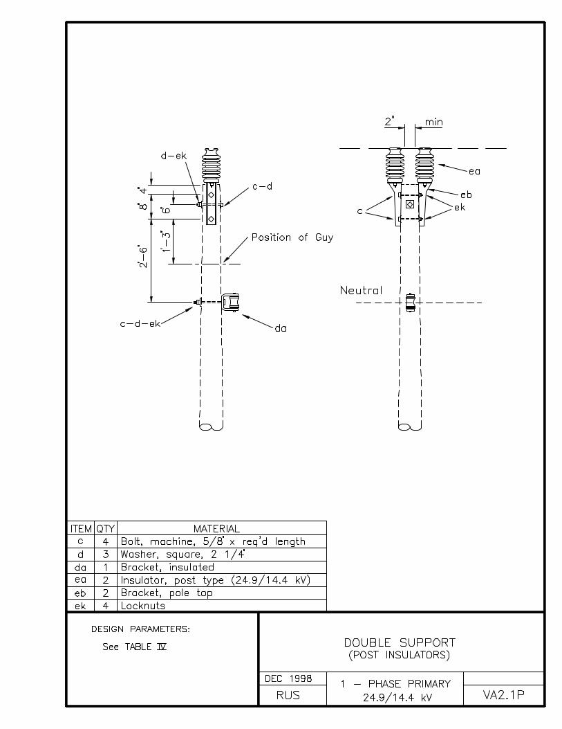
VA2.1 DOUBLE SUPPORT
VA2.1P DOUBLE SUPPORT (POST INSULATORS)
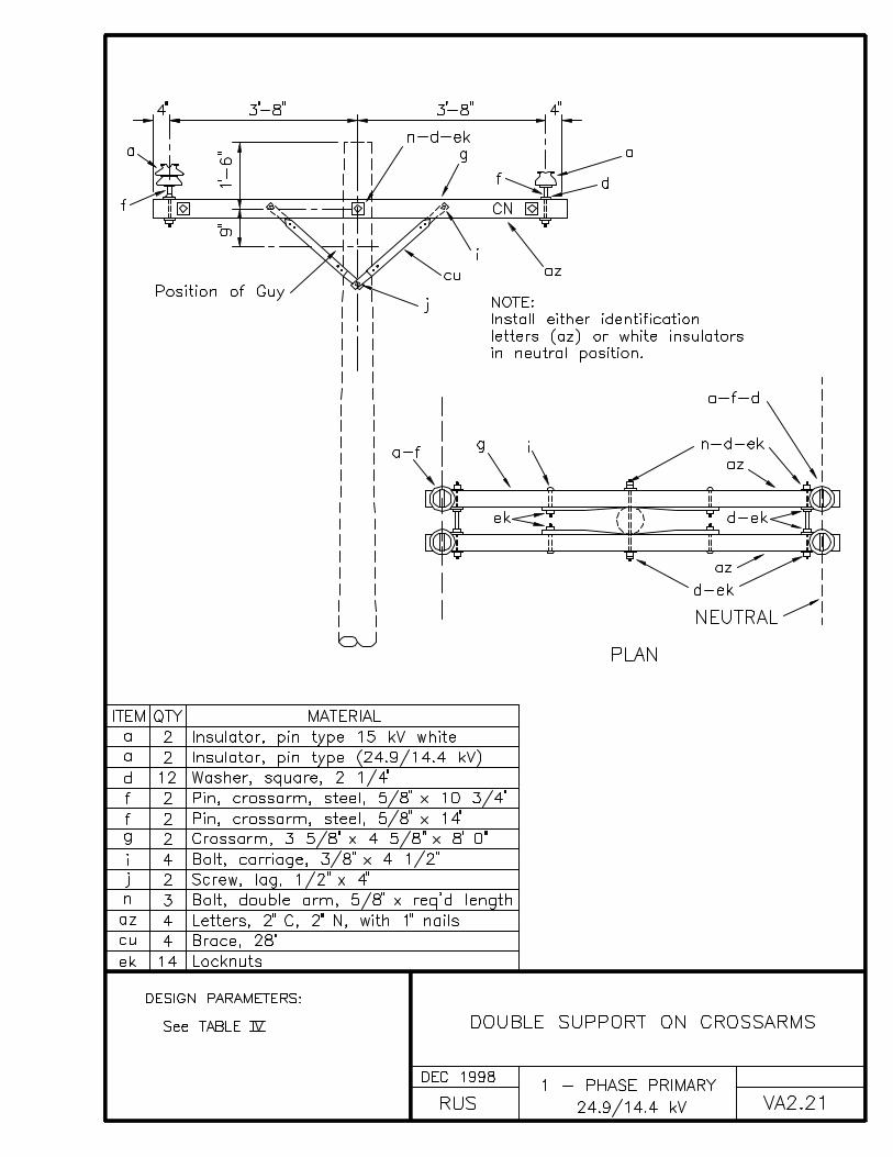
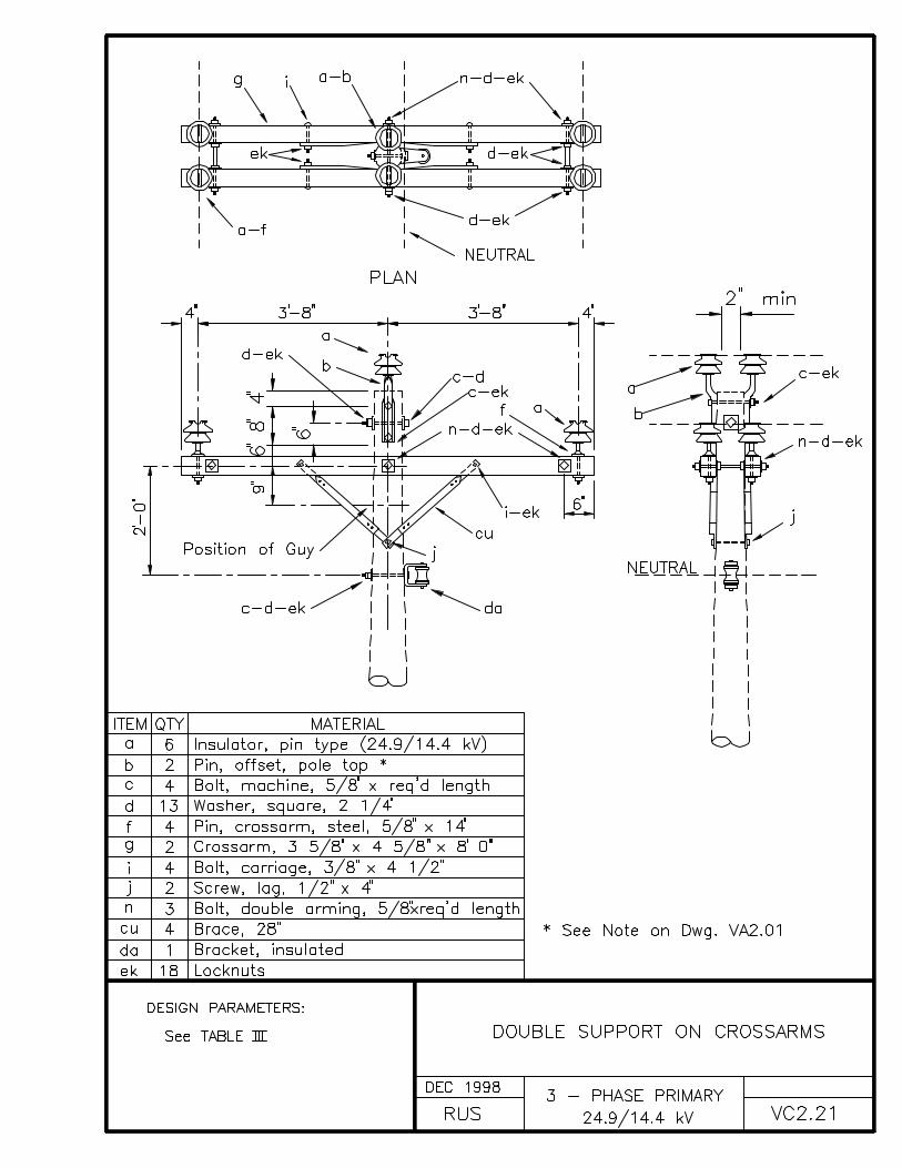
VA2.21 DOUBLE SUPPORT ON CROSSARMS
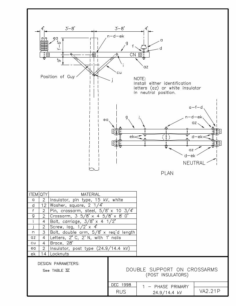
VA2.21P DOUBLE SUPPORT ON CROSSARMS (POST INSULATORS)
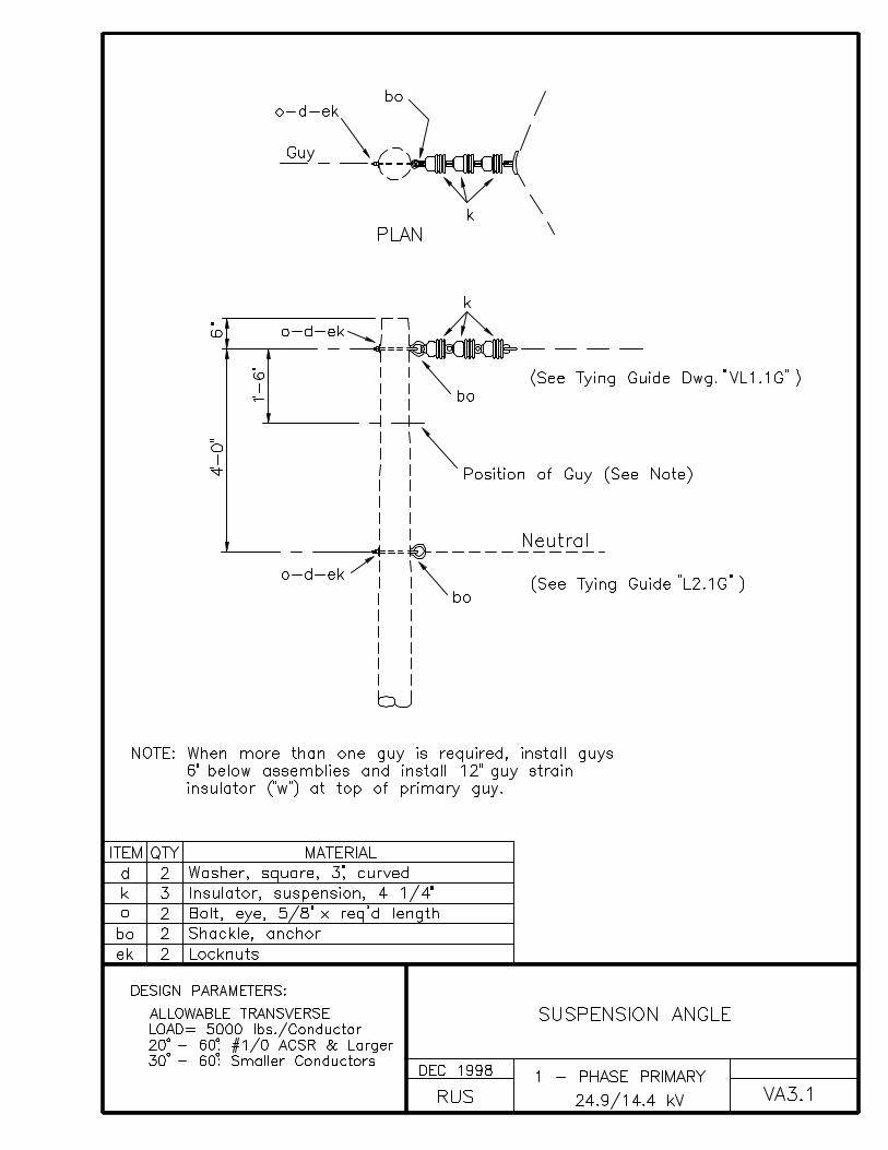
VA3.1 SUSPENSION ANGLE
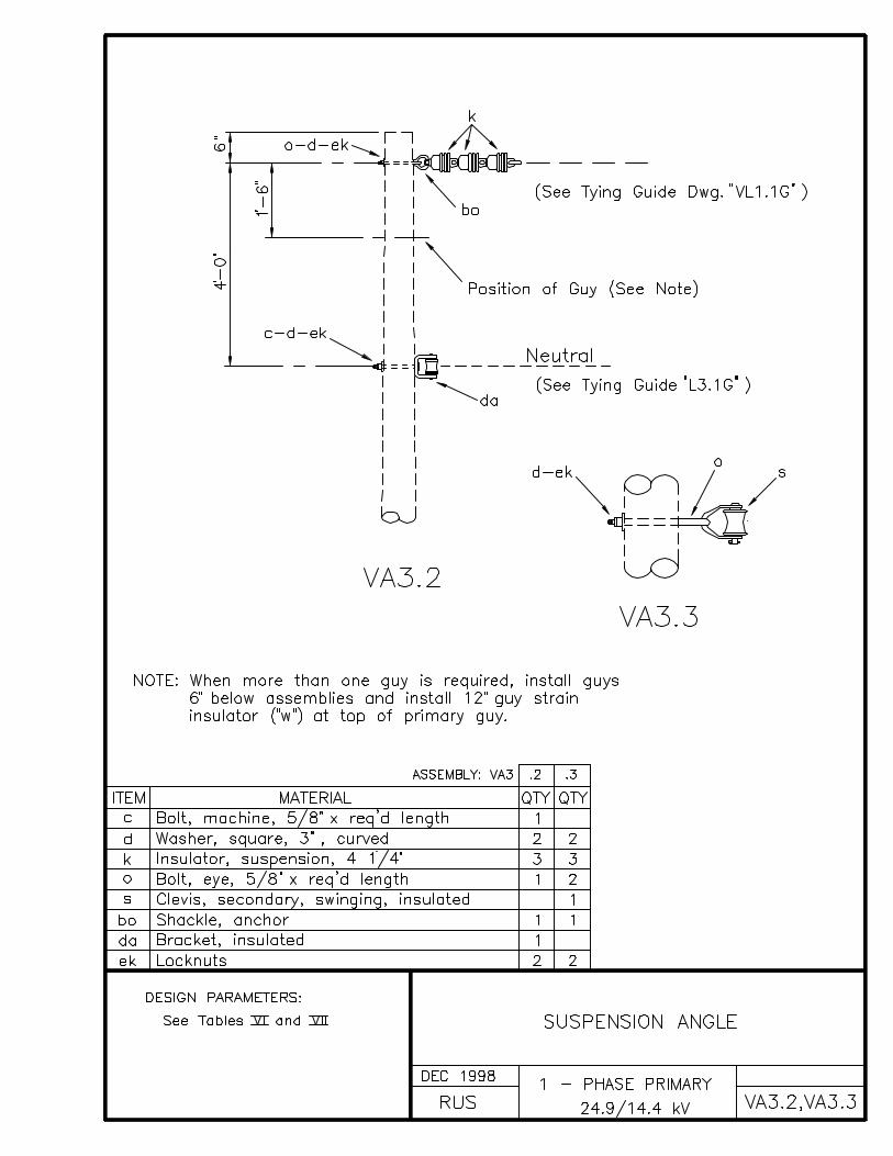
VA3.2, VA3.3 SUSPENSION ANGLE
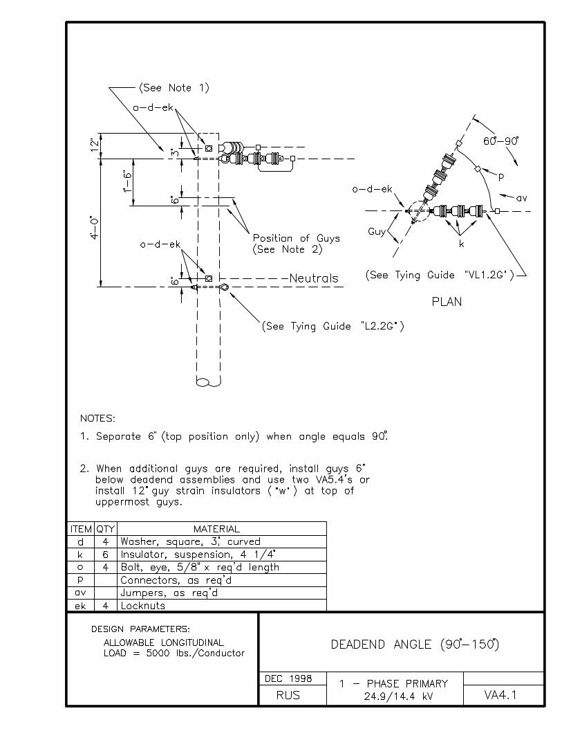
VA4.1 DEADEND ANGLE (90° - 150°)
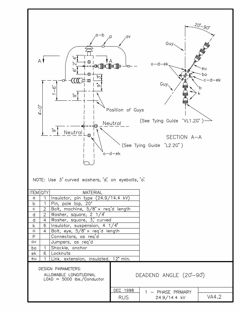
VA4.2 DEADEND ANGLE (20° - 90°)
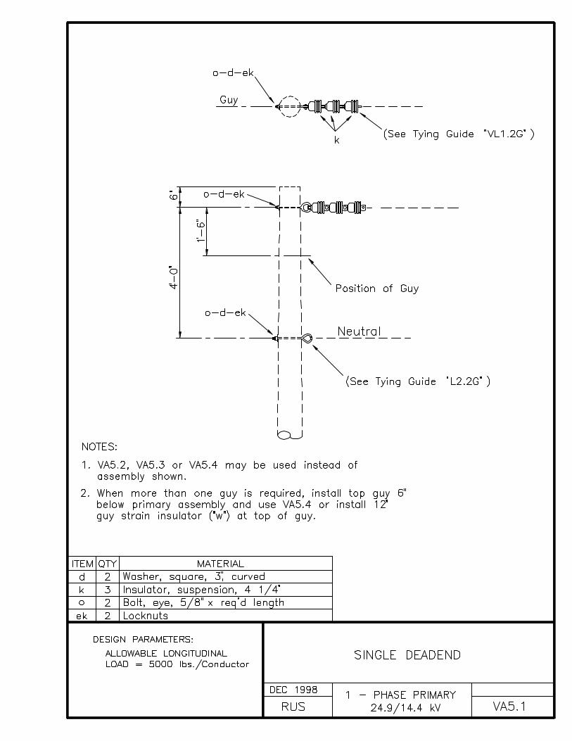
VA5.1 SINGLE DEADEND
VA5.2, VA5.3, VA5.4 SINGLE DEADENDS
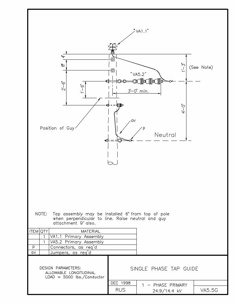
VA5.5G SINGLE PHASE TAP GUIDE
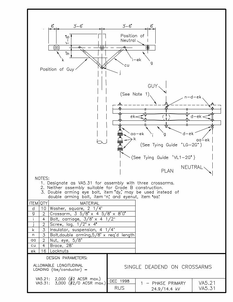
VA5.21, VA5.31 SINGLE DEADEND ON CROSSARMS
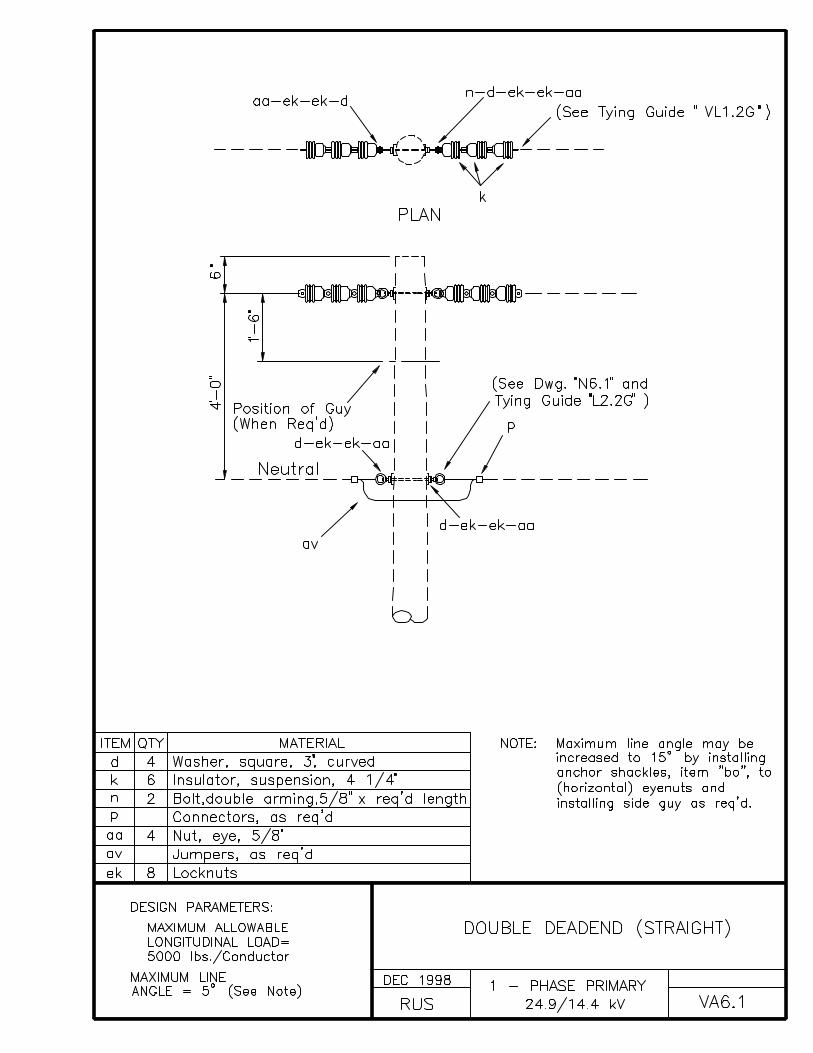
VA6.1 DOUBLE DEADEND (STRAIGHT)
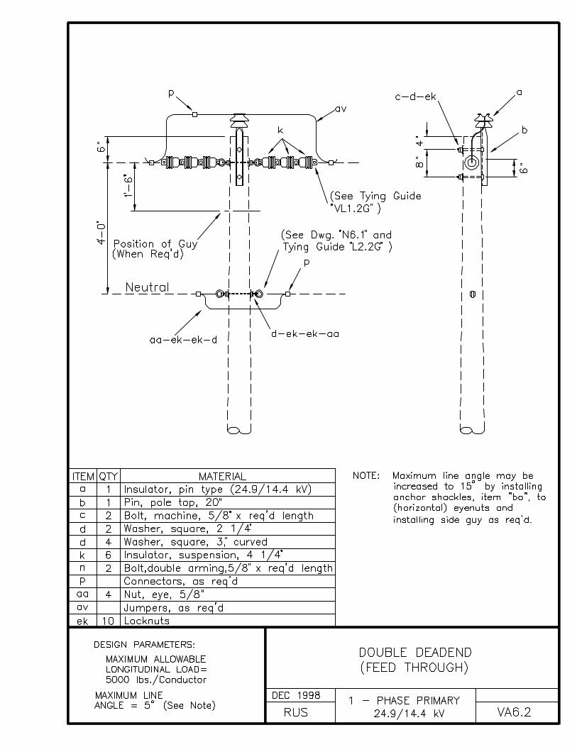
VA6.2 DOUBLE DEADEND (FEED THROUGH)
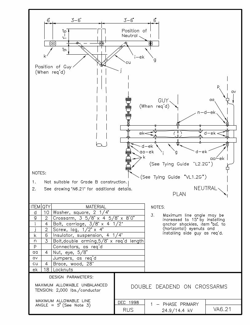
VA6.21 DOUBLE DEADEND ON CROSSARMS
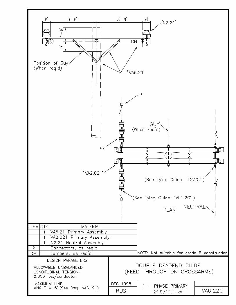
VA6.22G DOUBLE DEADEND GUIDE (FEED THROUGH ON CROSSARMS)

CONSTRUCTION SPECIFICATIONS FOR POLE TOP ASSEMBLIES
Line designs which use high poles to clear obstacles such asrailroads, must avoid upstrain on pin-type or post-typeinsulators on adjacent shorter poles.
The neutral conductor should be installed on the same side(preferably the road side) of all of the tangent and small anglepoles throughout the length of the line.
Prior RUS approval is given if it is under the circumstancesnecessary to lower the neutral attachment on standardconstruction pole top assemblies an additional distance notexceeding 2 feet for the purpose of economically meetingconductor clearance requirements of the NESC.
Prior RUS approval is given if it is under the circumstancesnecessary to lower the neutral attachment on standardconstruction pole top assemblies an additional distance of up to6 feet for the purpose of performing construction and future linemaintenance on these assemblies from bucket trucks designed forsuch work.
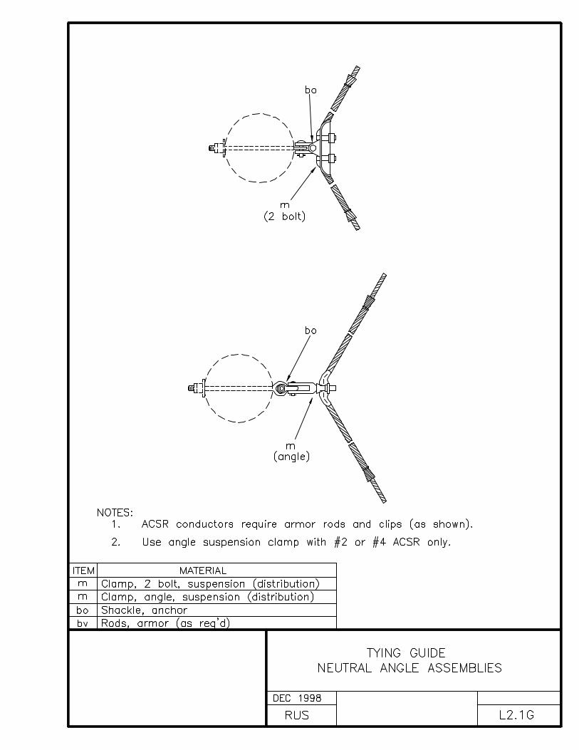
With pin-type or post-type insulators, the conductor must be tiedto the top groove of the insulator on tangent poles and on theside of the insulator away from the strain at angles. Pin-typeand post-type insulators must be tight on the pins and bracket,respectively, and the top groove must be in line with theconductor after tying.
Factory-formed ties must be installed in accordance with themanufacturer’s specifications and recommendations.
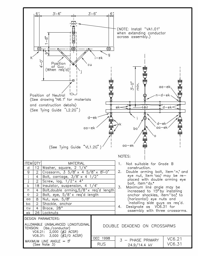
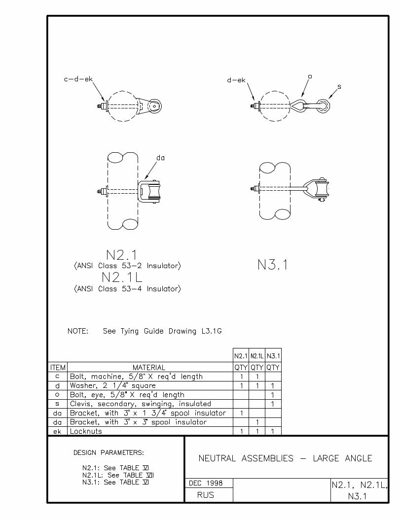
A 3 inch by 3 inch (minimum), square, curved washer, item “d”,shall be used abutting the pole when installing primary orneutral conductor deadend assemblies directly to the pole tomitigate the crushing of wood fibers and to facilitate theallowable longitudinal loading as given in the design parameterson the construction drawings.
A locknut must be installed with each nut and eyenut, on allmachine, upset and double arming bolts, and all other threadedhardware such as insulator pins and studs.
The calculated “maximum line angle” values in the tables arebased on the “designated maximum” transverse loading on insulatorpins as specified by RUS, and the application of the appropriateoverload factors from the 1997 edition of the NESC.

“Allowable longitudinal (or transverse) loading” values in thedesign parameters were derived from known or designated maximumstrengths of materials to which the appropriate NESC safetyfactors have already been applied.
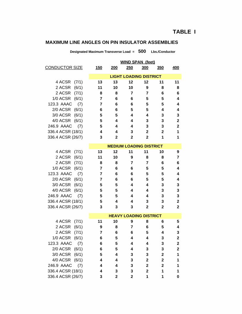
TABLE I
MAXIMUM LINE ANGLES ON PIN INSULATOR ASSEMBLIES
Designated Maximum Transverse Load = 500 Lbs./Conductor
WIND SPAN (feet)CONDUCTOR SIZE 150 200 250 300 350 400
LIGHT LOADING DISTRICT4 ACSR (7/1) 13 13 12 12 11 112 ACSR (6/1) 11 10 10 9 8 82 ACSR (7/1) 8 8 7 7 6 6
1/0 ACSR (6/1) 7 6 6 5 5 4123.3 AAAC (7) 7 6 6 5 5 4
2/0 ACSR (6/1) 6 6 5 5 4 43/0 ACSR (6/1) 5 5 4 4 3 34/0 ACSR (6/1) 5 4 4 3 3 2
246.9 AAAC (7) 5 4 4 3 3 2336.4 ACSR (18/1) 4 4 3 2 2 1336.4 ACSR (26/7) 3 2 2 2 1 1
MEDIUM LOADING DISTRICT4 ACSR (7/1) 13 12 11 11 10 92 ACSR (6/1) 11 10 9 8 8 72 ACSR (7/1) 8 8 7 7 6 6
1/0 ACSR (6/1) 7 6 6 5 5 4123.3 AAAC (7) 7 6 6 5 5 4
2/0 ACSR (6/1) 7 6 6 5 5 43/0 ACSR (6/1) 5 5 4 4 3 34/0 ACSR (6/1) 5 5 4 4 3 3
246.9 AAAC (7) 5 5 4 4 3 3336.4 ACSR (18/1) 5 4 4 3 3 2336.4 ACSR (26/7) 3 3 3 2 2 2
HEAVY LOADING DISTRICT4 ACSR (7/1) 11 10 9 8 6 52 ACSR (6/1) 9 8 7 6 5 42 ACSR (7/1) 7 6 6 5 4 3
1/0 ACSR (6/1) 6 5 4 4 3 2123.3 AAAC (7) 6 5 4 4 3 2
2/0 ACSR (6/1) 6 5 4 3 3 23/0 ACSR (6/1) 5 4 3 3 2 14/0 ACSR (6/1) 4 4 3 2 2 1
246.9 AAAC (7) 4 4 3 2 2 1336.4 ACSR (18/1) 4 3 3 2 1 1336.4 ACSR (26/7) 3 2 2 1 1 0

TABLE II
MAXIMUM LINE ANGLES ON PIN INSULATOR ASSEMBLIES
Designated Maximum Transverse Load = 750 Lbs./Conductor
WIND SPAN (feet)CONDUCTOR SIZE 150 200 250 300 350 400
LIGHT LOADING DISTRICT4 ACSR (7/1) 21 21 20 19 19 182 ACSR (6/1) 17 17 16 15 15 142 ACSR (7/1) 13 13 12 12 11 11
1/0 ACSR (6/1) 11 10 10 9 9 8123.3 AAAC (7) 11 10 10 9 9 8
2/0 ACSR (6/1) 11 10 9 9 8 83/0 ACSR (6/1) 8 8 7 7 6 64/0 ACSR (6/1) 8 8 7 6 6 5
246.9 AAAC (7) 8 7 7 6 6 5336.4 ACSR (18/1) 7 7 6 5 5 4336.4 ACSR (26/7) 5 5 4 4 3 3
MEDIUM LOADING DISTRICT4 ACSR (7/1) 21 20 19 18 18 172 ACSR (6/1) 17 16 16 15 14 132 ACSR (7/1) 13 13 12 12 11 10
1/0 ACSR (6/1) 11 10 10 9 9 8123.3 AAAC (7) 11 10 10 9 9 8
2/0 ACSR (6/1) 11 10 10 9 9 83/0 ACSR (6/1) 8 8 8 7 7 64/0 ACSR (6/1) 8 8 7 7 6 6
246.9 AAAC (7) 8 8 7 7 6 6336.4 ACSR (18/1) 8 7 7 6 6 5336.4 ACSR (26/7) 5 5 5 4 4 4
HEAVY LOADING DISTRICT4 ACSR (7/1) 19 18 17 15 14 132 ACSR (6/1) 16 15 13 12 11 102 ACSR (7/1) 12 11 10 10 9 8
1/0 ACSR (6/1) 10 9 8 8 7 6123.3 AAAC (7) 10 9 8 8 7 6
2/0 ACSR (6/1) 10 9 8 7 7 63/0 ACSR (6/1) 8 7 7 6 5 54/0 ACSR (6/1) 8 7 6 6 5 4
246.9 AAAC (7) 7 7 6 6 5 4336.4 ACSR (18/1) 7 7 6 5 4 4336.4 ACSR (26/7) 5 5 4 4 3 3
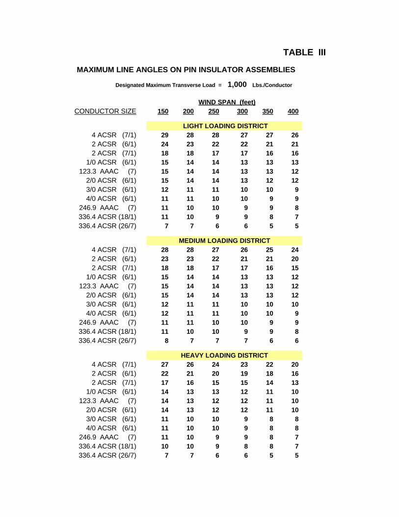
TABLE III
MAXIMUM LINE ANGLES ON PIN INSULATOR ASSEMBLIES
Designated Maximum Transverse Load = 1,000 Lbs./Conductor
WIND SPAN (feet)CONDUCTOR SIZE 150 200 250 300 350 400
LIGHT LOADING DISTRICT4 ACSR (7/1) 29 28 28 27 27 262 ACSR (6/1) 24 23 22 22 21 212 ACSR (7/1) 18 18 17 17 16 16
1/0 ACSR (6/1) 15 14 14 13 13 13123.3 AAAC (7) 15 14 14 13 13 12
2/0 ACSR (6/1) 15 14 14 13 12 123/0 ACSR (6/1) 12 11 11 10 10 94/0 ACSR (6/1) 11 11 10 10 9 9
246.9 AAAC (7) 11 10 10 9 9 8336.4 ACSR (18/1) 11 10 9 9 8 7336.4 ACSR (26/7) 7 7 6 6 5 5
MEDIUM LOADING DISTRICT4 ACSR (7/1) 28 28 27 26 25 242 ACSR (6/1) 23 23 22 21 21 202 ACSR (7/1) 18 18 17 17 16 15
1/0 ACSR (6/1) 15 14 14 13 13 12123.3 AAAC (7) 15 14 14 13 13 12
2/0 ACSR (6/1) 15 14 14 13 13 123/0 ACSR (6/1) 12 11 11 10 10 104/0 ACSR (6/1) 12 11 11 10 10 9
246.9 AAAC (7) 11 11 10 10 9 9336.4 ACSR (18/1) 11 10 10 9 9 8336.4 ACSR (26/7) 8 7 7 7 6 6
HEAVY LOADING DISTRICT4 ACSR (7/1) 27 26 24 23 22 202 ACSR (6/1) 22 21 20 19 18 162 ACSR (7/1) 17 16 15 15 14 13
1/0 ACSR (6/1) 14 13 13 12 11 10123.3 AAAC (7) 14 13 12 12 11 10
2/0 ACSR (6/1) 14 13 12 12 11 103/0 ACSR (6/1) 11 10 10 9 8 84/0 ACSR (6/1) 11 10 10 9 8 8
246.9 AAAC (7) 11 10 9 9 8 7336.4 ACSR (18/1) 10 10 9 8 8 7336.4 ACSR (26/7) 7 7 6 6 5 5
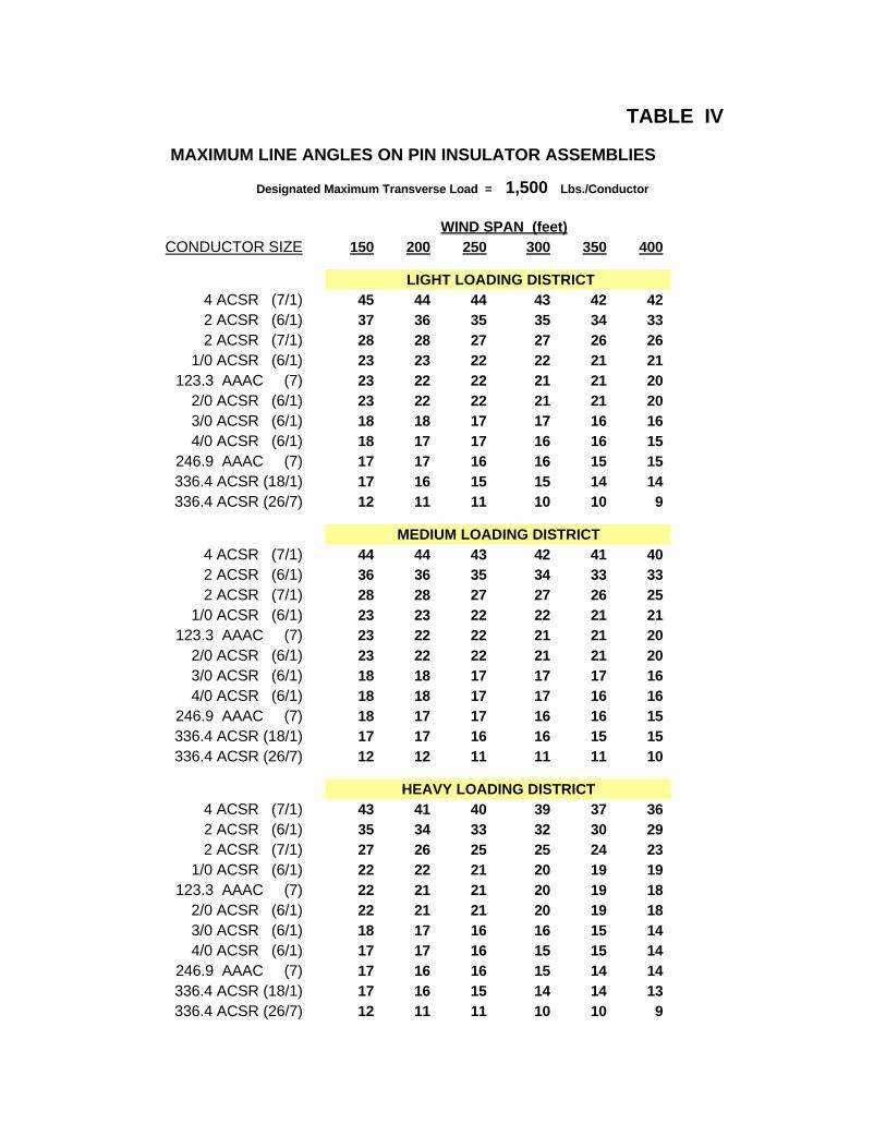
TABLE IV
MAXIMUM LINE ANGLES ON PIN INSULATOR ASSEMBLIES
Designated Maximum Transverse Load = 1,500 Lbs./Conductor
WIND SPAN (feet)CONDUCTOR SIZE 150 200 250 300 350 400
LIGHT LOADING DISTRICT4 ACSR (7/1) 45 44 44 43 42 422 ACSR (6/1) 37 36 35 35 34 332 ACSR (7/1) 28 28 27 27 26 26
1/0 ACSR (6/1) 23 23 22 22 21 21123.3 AAAC (7) 23 22 22 21 21 20
2/0 ACSR (6/1) 23 22 22 21 21 203/0 ACSR (6/1) 18 18 17 17 16 164/0 ACSR (6/1) 18 17 17 16 16 15
246.9 AAAC (7) 17 17 16 16 15 15336.4 ACSR (18/1) 17 16 15 15 14 14336.4 ACSR (26/7) 12 11 11 10 10 9
MEDIUM LOADING DISTRICT4 ACSR (7/1) 44 44 43 42 41 402 ACSR (6/1) 36 36 35 34 33 332 ACSR (7/1) 28 28 27 27 26 25
1/0 ACSR (6/1) 23 23 22 22 21 21123.3 AAAC (7) 23 22 22 21 21 20
2/0 ACSR (6/1) 23 22 22 21 21 203/0 ACSR (6/1) 18 18 17 17 17 164/0 ACSR (6/1) 18 18 17 17 16 16
246.9 AAAC (7) 18 17 17 16 16 15336.4 ACSR (18/1) 17 17 16 16 15 15336.4 ACSR (26/7) 12 12 11 11 11 10
HEAVY LOADING DISTRICT4 ACSR (7/1) 43 41 40 39 37 362 ACSR (6/1) 35 34 33 32 30 292 ACSR (7/1) 27 26 25 25 24 23
1/0 ACSR (6/1) 22 22 21 20 19 19123.3 AAAC (7) 22 21 21 20 19 18
2/0 ACSR (6/1) 22 21 21 20 19 183/0 ACSR (6/1) 18 17 16 16 15 144/0 ACSR (6/1) 17 17 16 15 15 14
246.9 AAAC (7) 17 16 16 15 14 14336.4 ACSR (18/1) 17 16 15 14 14 13336.4 ACSR (26/7) 12 11 11 10 10 9

TABLE V
MAXIMUM LINE ANGLES ON PIN INSULATOR ASSEMBLIES
Designated Maximum Transverse Load = 2,000 Lbs./Conductor
WIND SPAN (feet)CONDUCTOR SIZE 150 200 250 300 350 400
LIGHT LOADING DISTRICT4 ACSR (7/1) 60 60 60 60 59 592 ACSR (6/1) 50 50 49 48 48 472 ACSR (7/1) 39 38 38 37 37 36
1/0 ACSR (6/1) 32 31 31 30 30 29123.3 AAAC (7) 31 31 30 30 29 29
2/0 ACSR (6/1) 31 31 30 30 29 283/0 ACSR (6/1) 25 24 24 23 23 224/0 ACSR (6/1) 24 24 23 23 22 22
246.9 AAAC (7) 24 23 23 22 22 21336.4 ACSR (18/1) 23 22 22 21 20 20336.4 ACSR (26/7) 16 16 15 15 14 14
MEDIUM LOADING DISTRICT4 ACSR (7/1) 60 60 60 59 58 572 ACSR (6/1) 50 49 48 48 47 462 ACSR (7/1) 39 38 37 37 36 36
1/0 ACSR (6/1) 32 31 31 30 30 29123.3 AAAC (7) 31 31 30 30 29 29
2/0 ACSR (6/1) 31 31 30 30 29 293/0 ACSR (6/1) 25 24 24 24 23 234/0 ACSR (6/1) 25 24 24 23 23 22
246.9 AAAC (7) 24 24 23 23 22 22336.4 ACSR (18/1) 24 23 23 22 22 21336.4 ACSR (26/7) 16 16 16 15 15 15
HEAVY LOADING DISTRICT4 ACSR (7/1) 60 58 57 55 54 522 ACSR (6/1) 49 47 46 45 44 432 ACSR (7/1) 38 37 36 35 34 33
1/0 ACSR (6/1) 31 30 29 28 28 27123.3 AAAC (7) 30 30 29 28 27 26
2/0 ACSR (6/1) 30 30 29 28 27 263/0 ACSR (6/1) 24 24 23 22 22 214/0 ACSR (6/1) 24 23 23 22 21 21
246.9 AAAC (7) 23 23 22 21 21 20336.4 ACSR (18/1) 23 22 21 21 20 19336.4 ACSR (26/7) 16 16 15 14 14 13

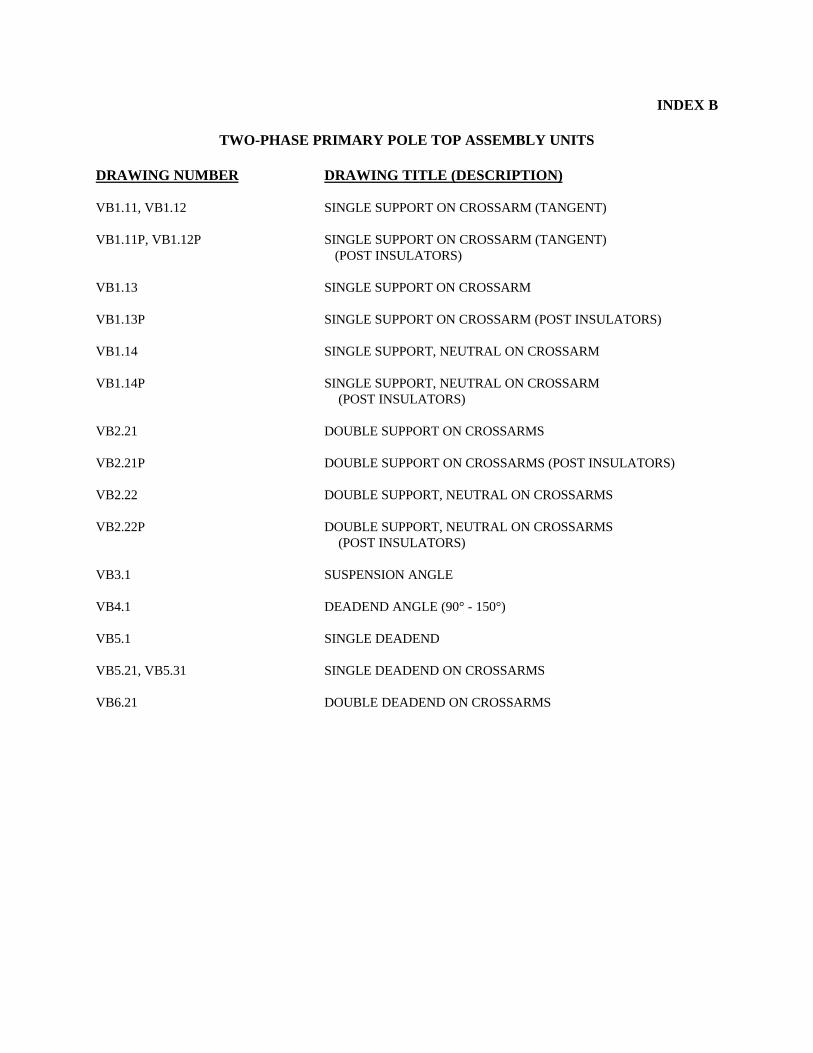
INDEX B
TWO-PHASE PRIMARY POLE TOP ASSEMBLY UNITS
DRAWING NUMBER DRAWING TITLE (DESCRIPTION)
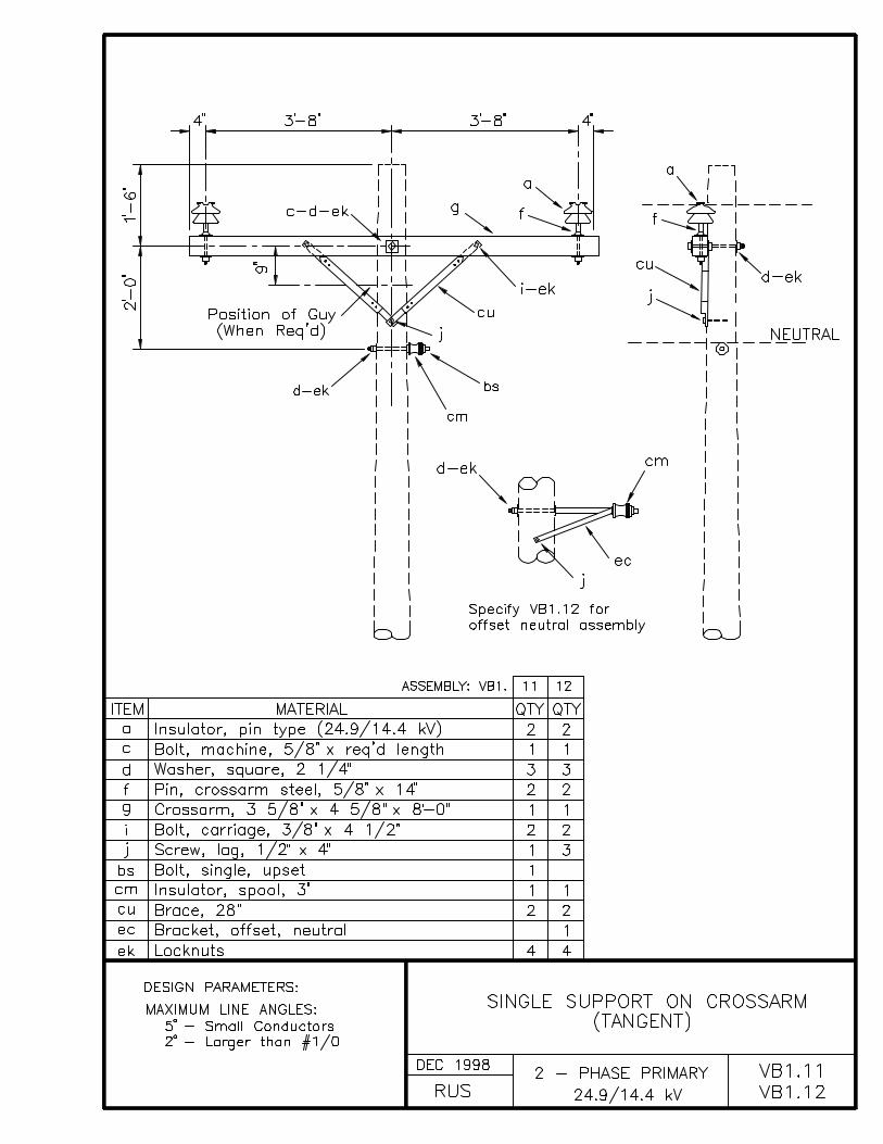
VB1.11, VB1.12 SINGLE SUPPORT ON CROSSARM (TANGENT)
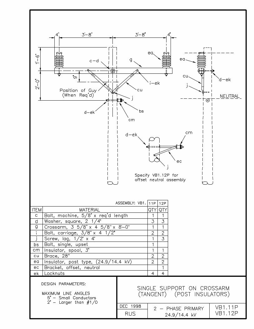
VB1.11P, VB1.12P SINGLE SUPPORT ON CROSSARM (TANGENT) (POST INSULATORS)
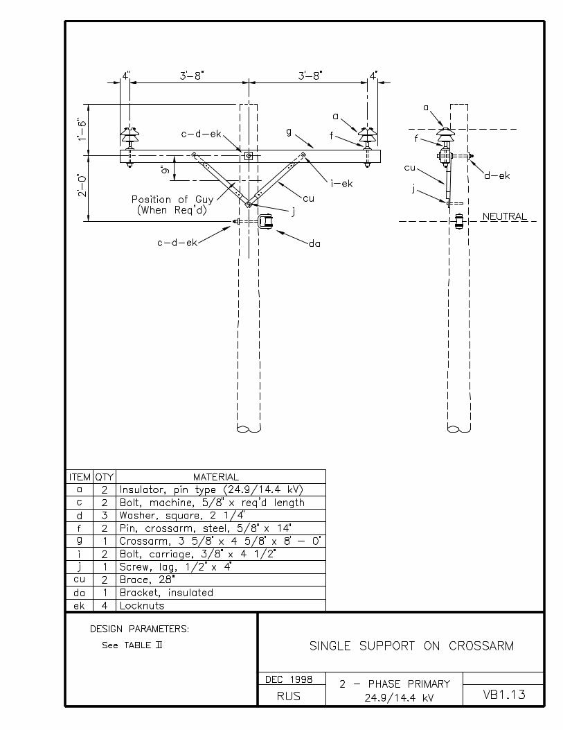
VB1.13 SINGLE SUPPORT ON CROSSARM
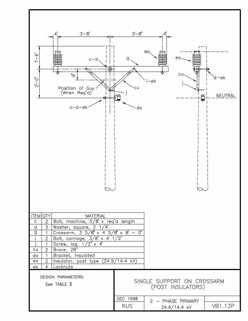
VB1.13P SINGLE SUPPORT ON CROSSARM (POST INSULATORS)
VB1.14 SINGLE SUPPORT, NEUTRAL ON CROSSARM
VB1.14P SINGLE SUPPORT, NEUTRAL ON CROSSARM (POST INSULATORS)
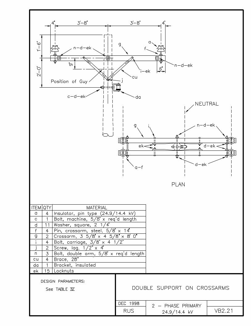
VB2.21 DOUBLE SUPPORT ON CROSSARMS
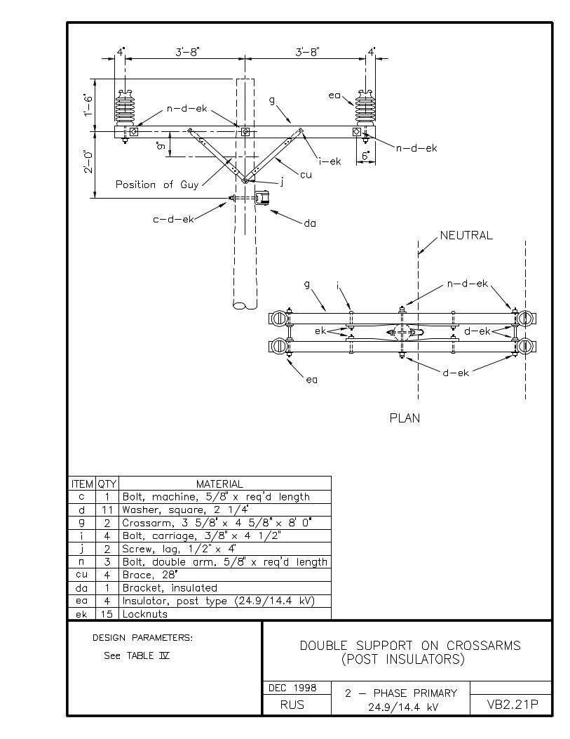
VB2.21P DOUBLE SUPPORT ON CROSSARMS (POST INSULATORS)
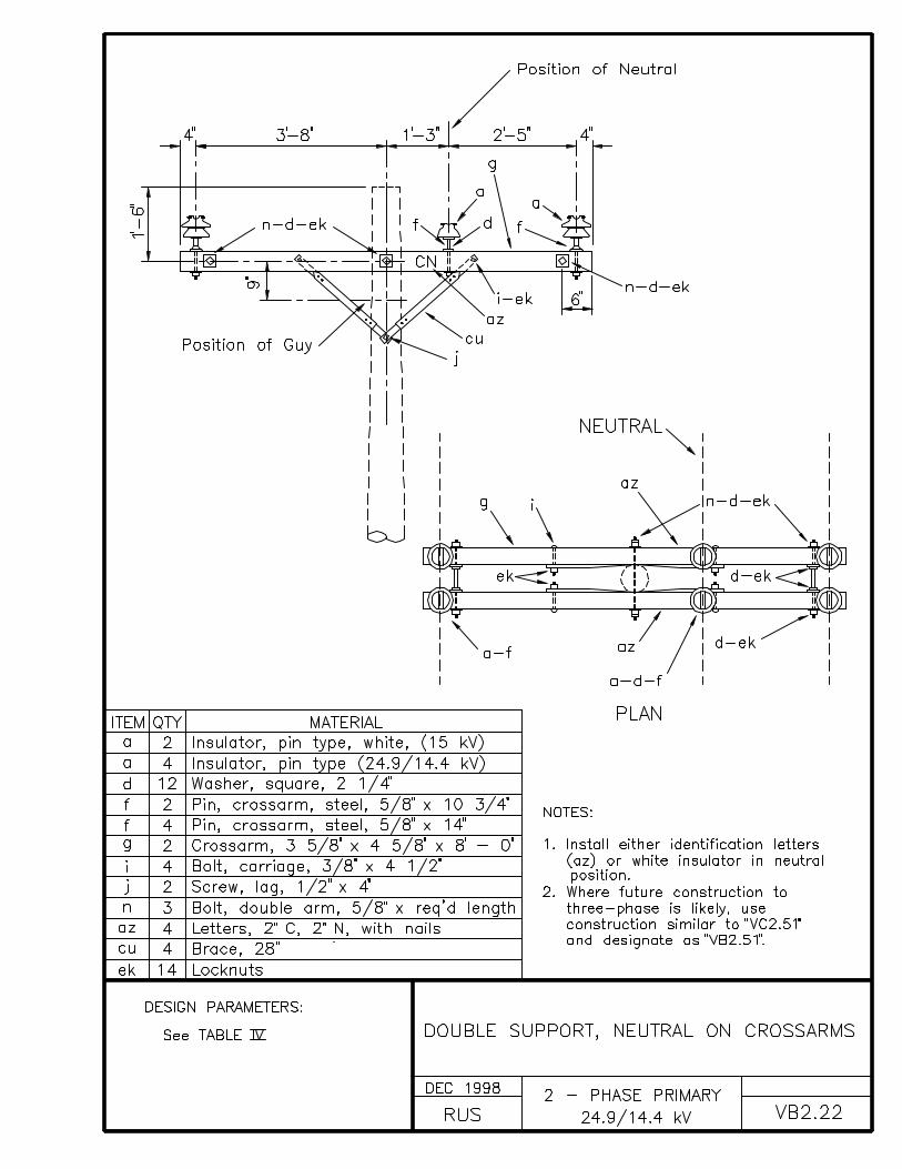
VB2.22 DOUBLE SUPPORT, NEUTRAL ON CROSSARMS
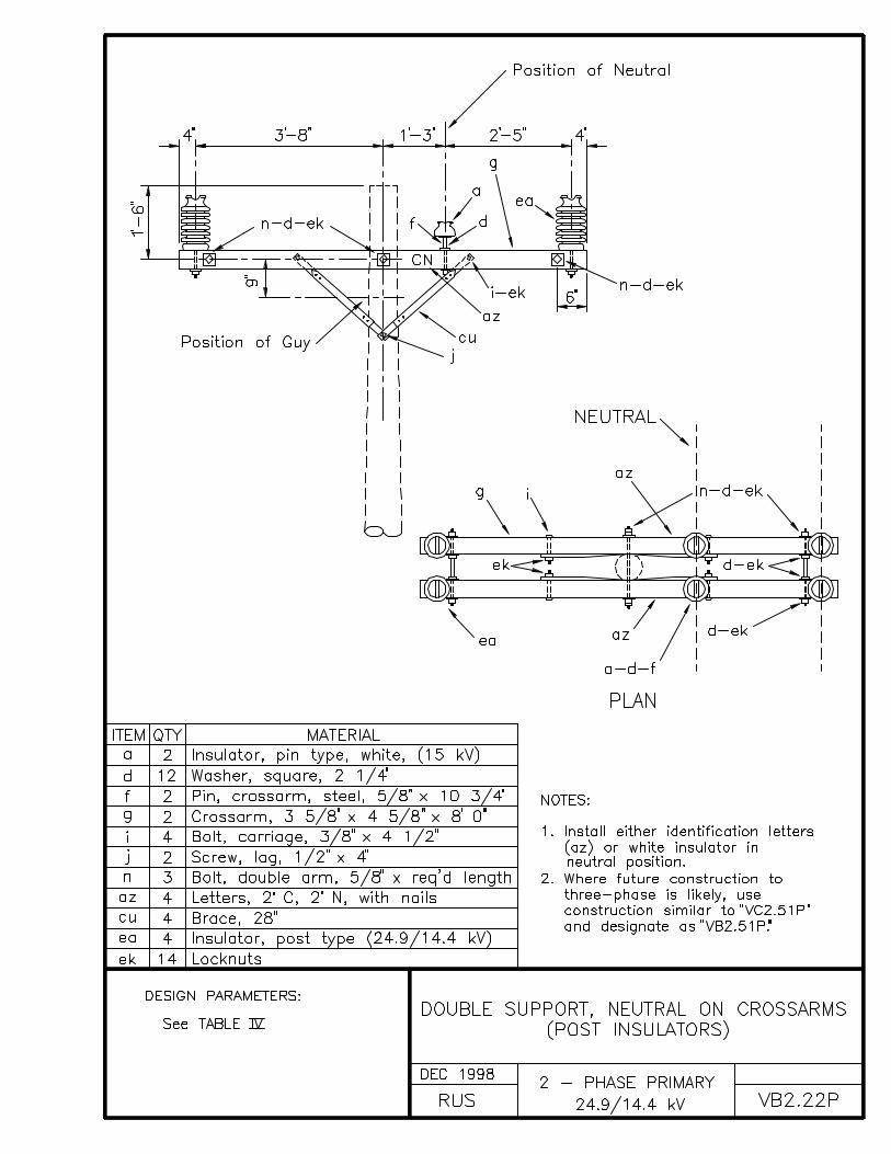
VB2.22P DOUBLE SUPPORT, NEUTRAL ON CROSSARMS (POST INSULATORS)
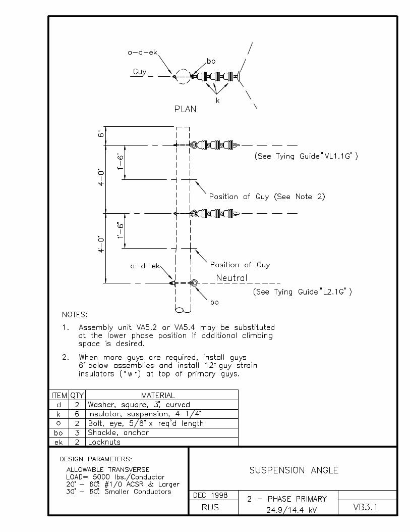
VB3.1 SUSPENSION ANGLE
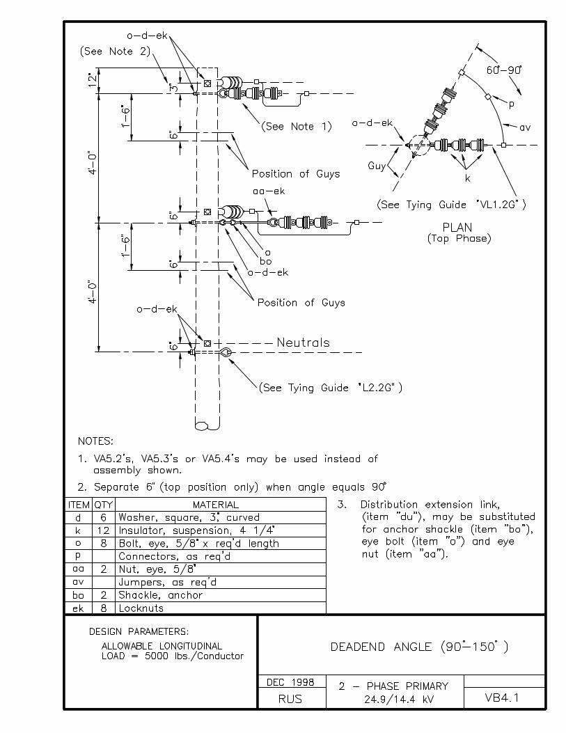
VB4.1 DEADEND ANGLE (90° - 150°)
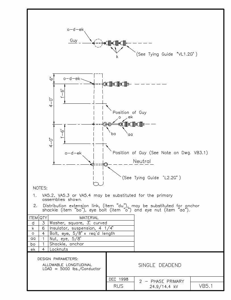
VB5.1 SINGLE DEADEND
VB5.21, VB5.31 SINGLE DEADEND ON CROSSARMS
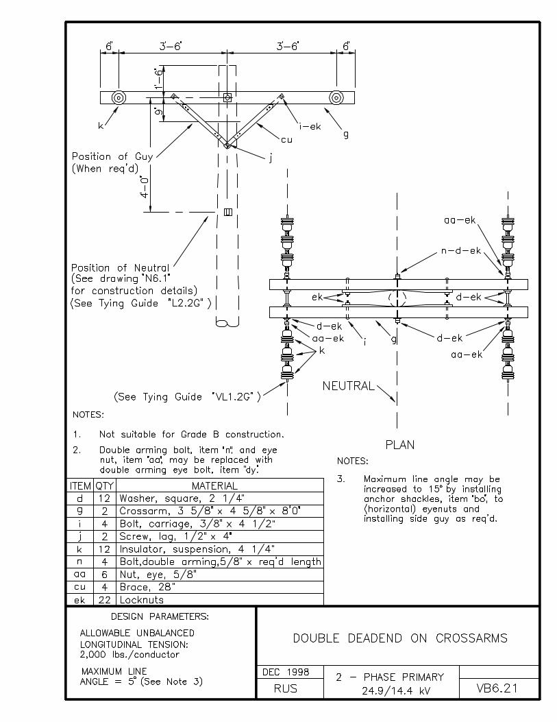
VB6.21 DOUBLE DEADEND ON CROSSARMS


INDEX C
THREE-PHASE PRIMARY POLE TOP ASSEMBLY UNITS
DRAWING NUMBER DRAWING TITLE (DESCRIPTION)
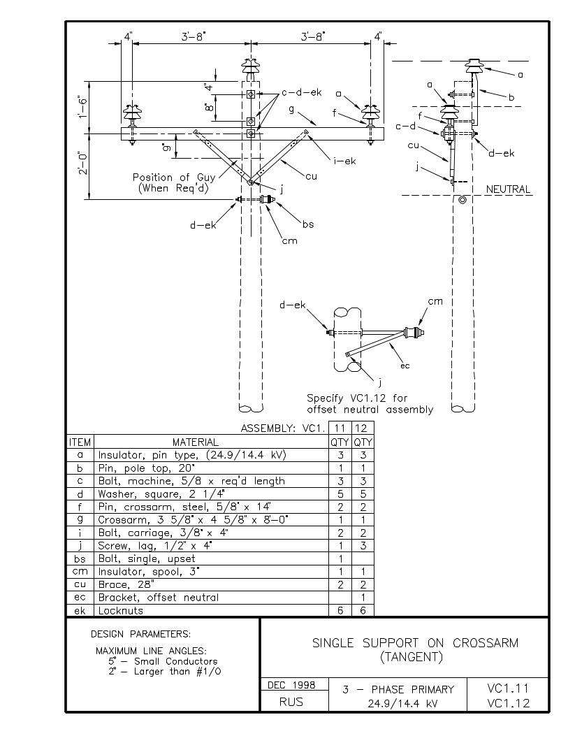
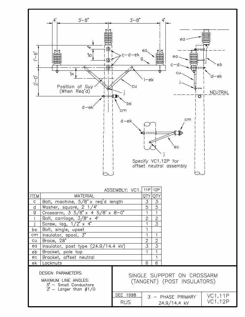
VC1.11, VC1.12 SINGLE SUPPORT ON CROSSARM (TANGENT)
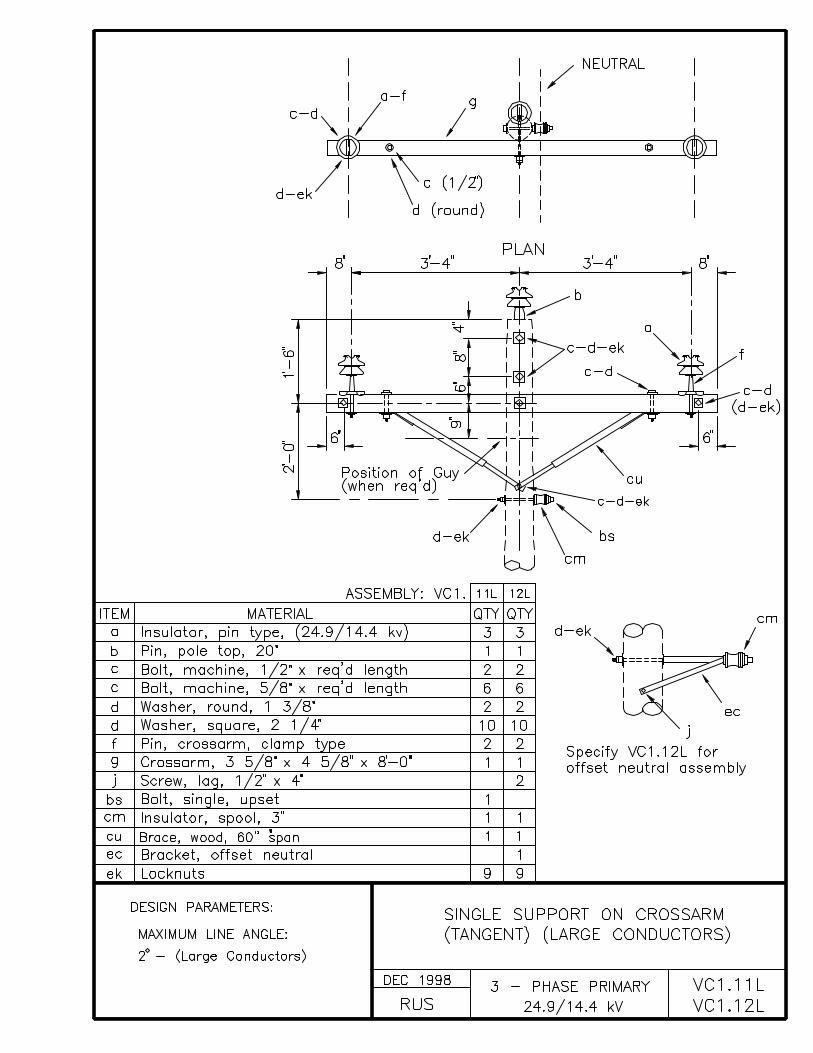
VC1.11L, VC1.12L SINGLE SUPPORT ON CROSSARM (TANGENT) (LARGE CONDUCTORS)
VC1.11P, VC1.12P SINGLE SUPPORT ON CROSSARM (TANGENT) (POST INSULATORS)
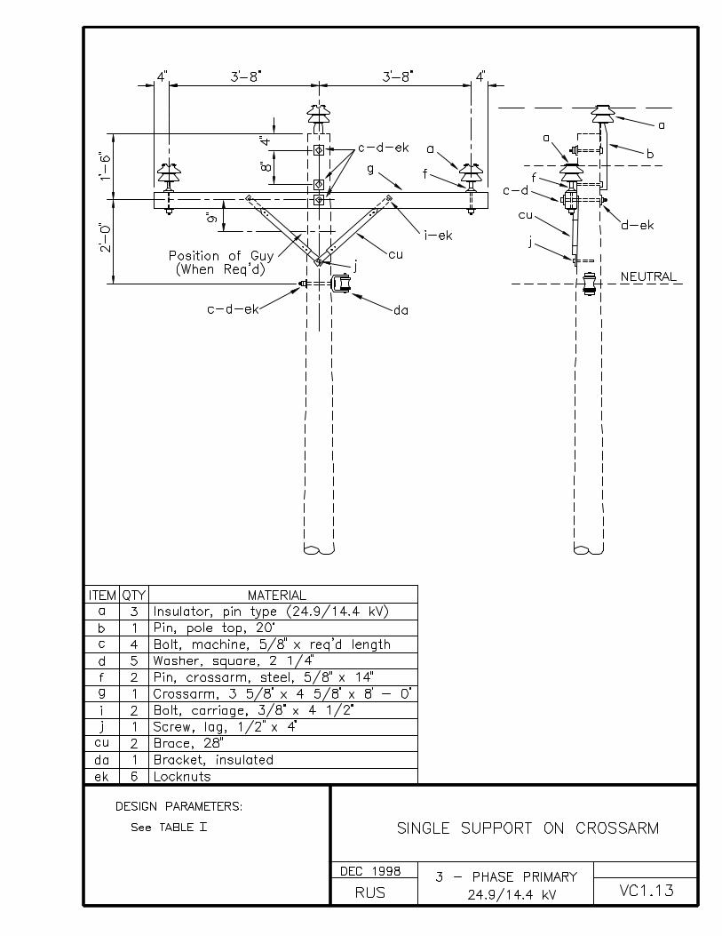
VC1.13 SINGLE SUPPORT ON CROSSARM
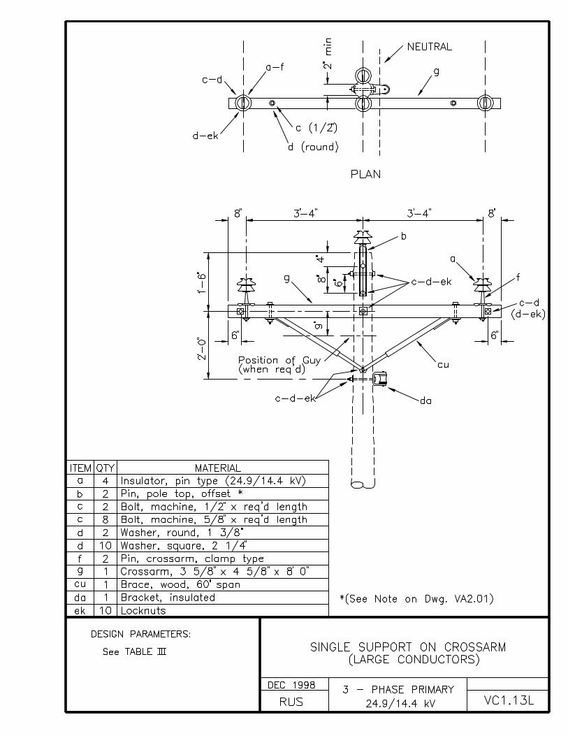
VC1.13L SINGLE SUPPORT ON CROSSARM (LARGE CONDUCTORS)
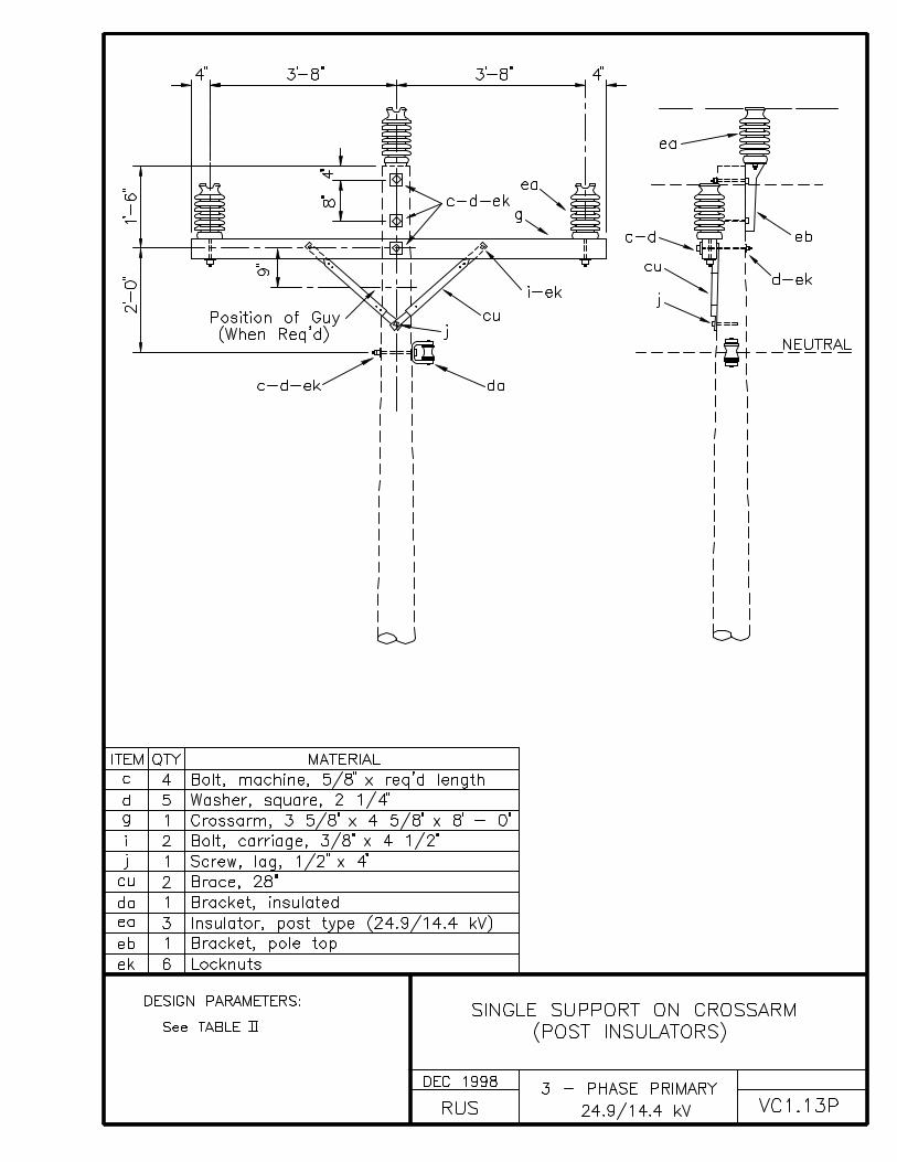
VC1.13P SINGLE SUPPORT ON CROSSARM (POST INSULATORS)
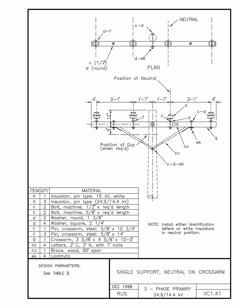
VC1.41 SINGLE SUPPORT, NEUTRAL ON CROSSARM
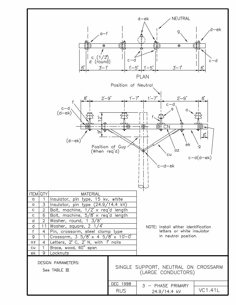
VC1.41L SINGLE SUPPORT, NEUTRAL ON CROSSARM (LARGE CONDUCTORS)
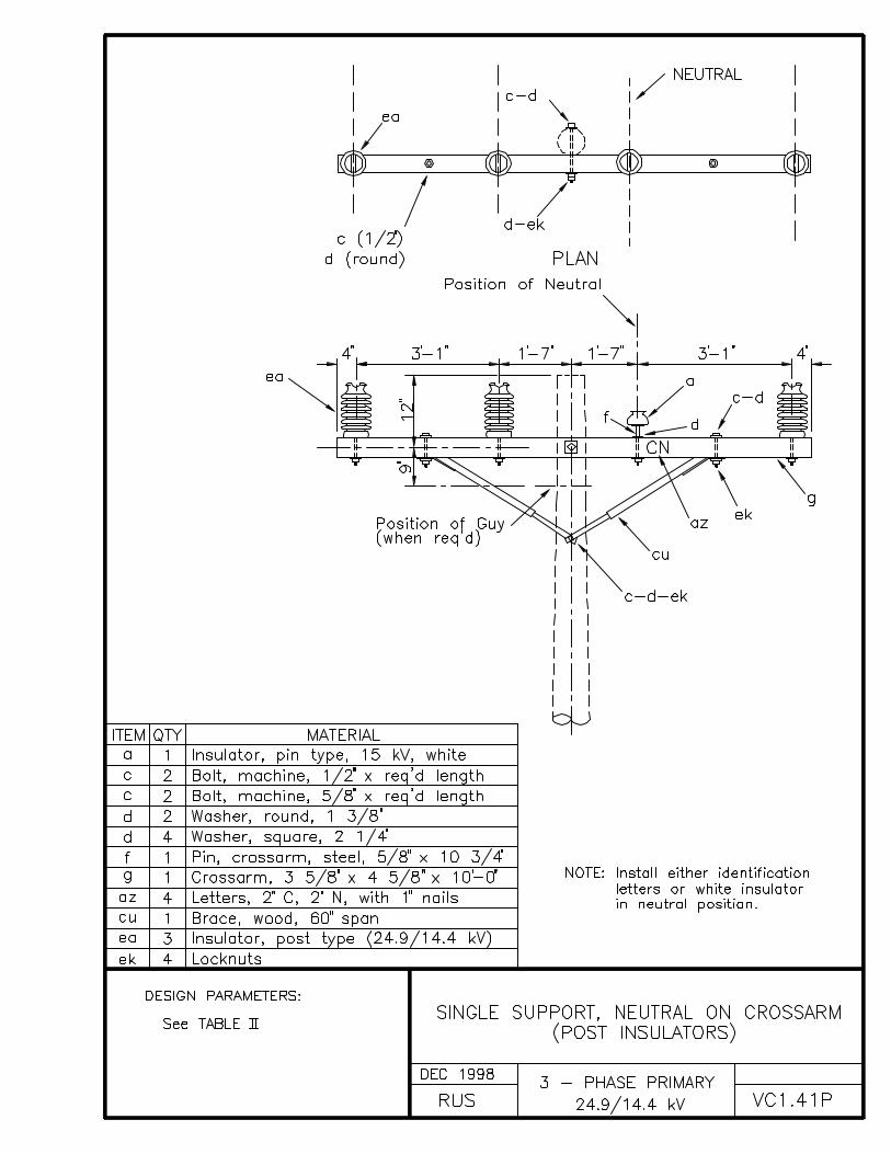
VC1.41P SINGLE SUPPORT, NEUTRAL ON CROSSARM (POST INSULATORS)
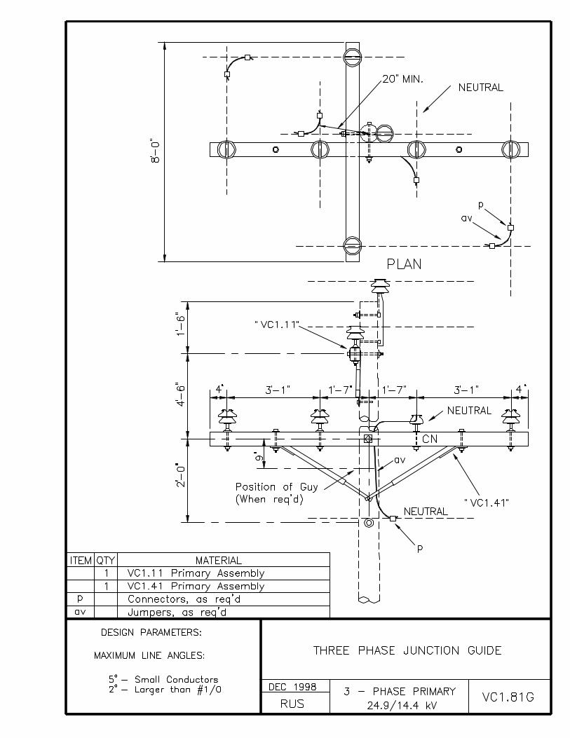
VC1.81G THREE-PHASE JUNCTION GUIDE
VC2.21 DOUBLE SUPPORT ON CROSSARMS
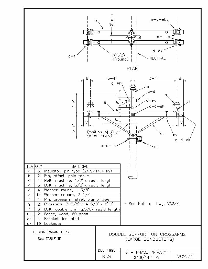
VC2.21L DOUBLE SUPPORT ON CROSSARMS (LARGE CONDUCTORS)
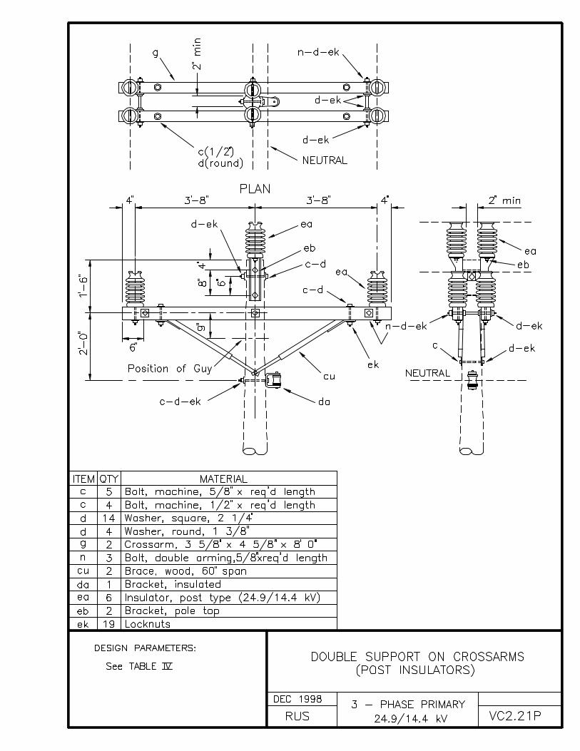
VC2.21P DOUBLE SUPPORT ON CROSSARMS (POST INSULATORS)
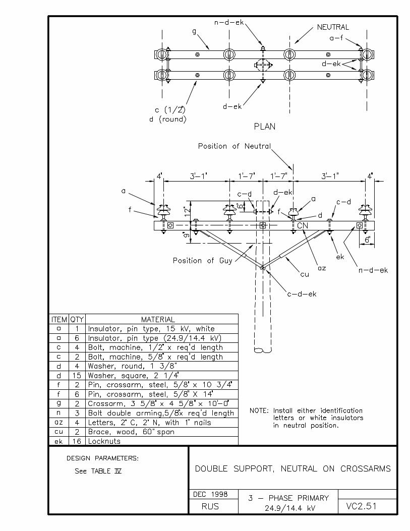
VC2.51 DOUBLE SUPPORT, NEUTRAL ON CROSSARMS
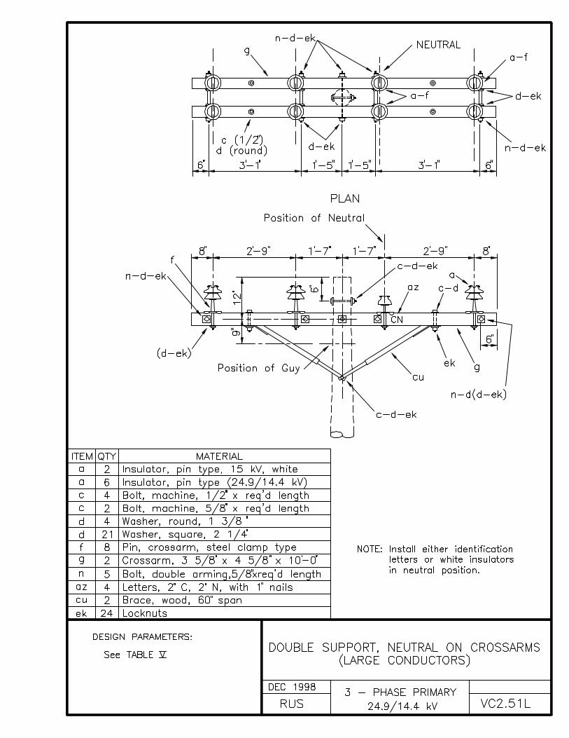
VC2.51L DOUBLE SUPPORT, NEUTRAL ON CROSSARMS (LARGE CONDUCTORS)
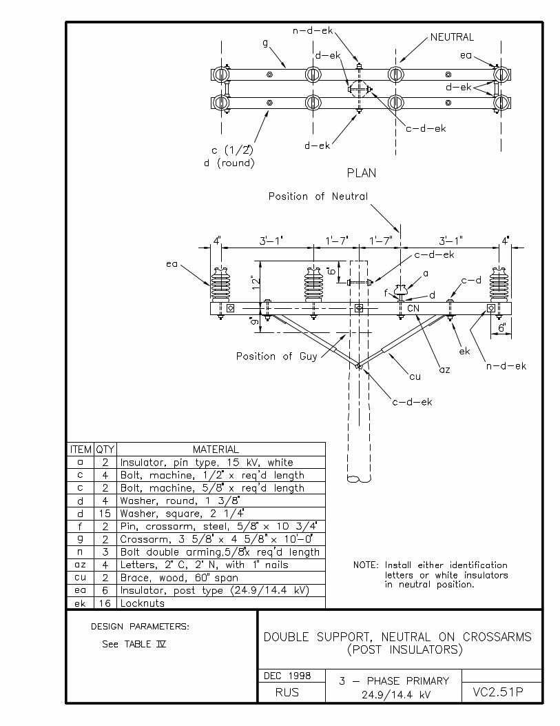
VC2.51P DOUBLE SUPPORT, NEUTRAL ON CROSSARMS (POST INSULATORS)
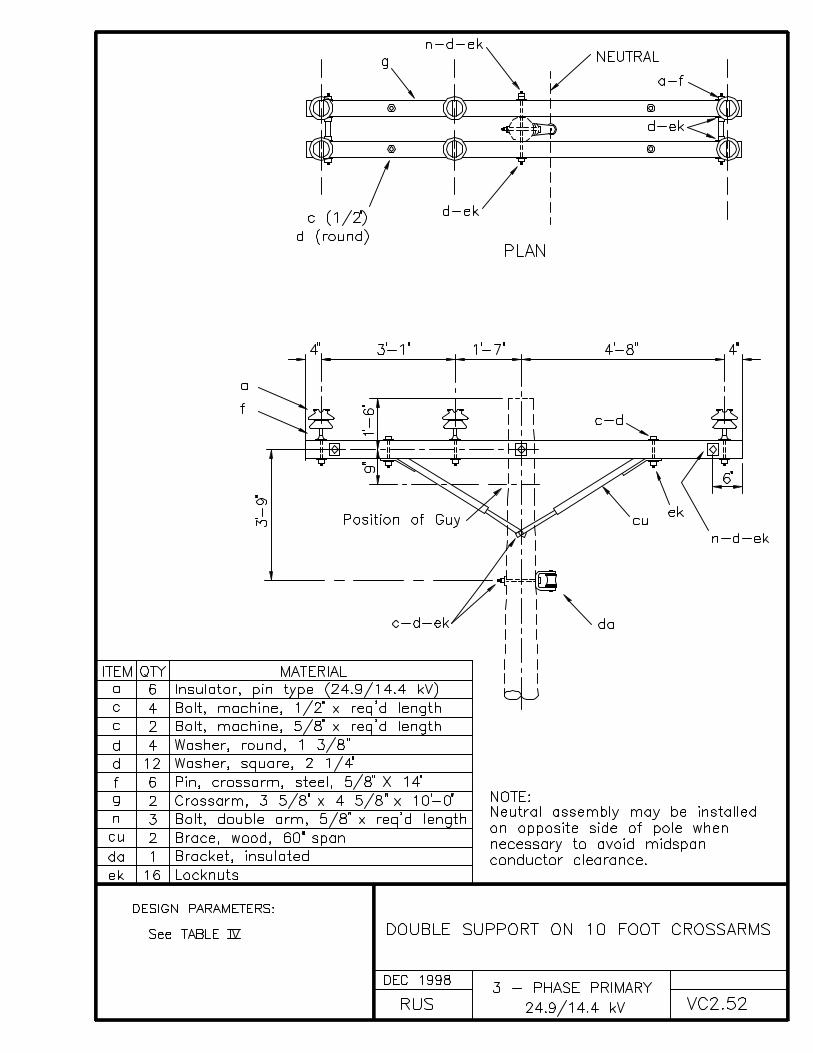
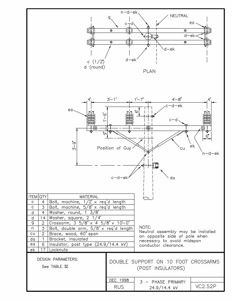
VC2.52 DOUBLE SUPPORT ON 10 FOOT CROSSARMS
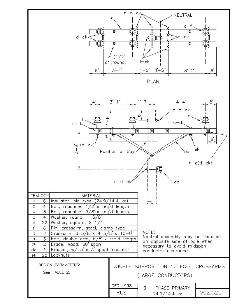
VC2.52L DOUBLE SUPPORT ON 10 FOOT CROSSARMS (LARGE CONDUCTORS)
INDEX C(page 2)
THREE-PHASE PRIMARY POLE TOP ASSEMBLY UNITS
DRAWING NUMBER DRAWING TITLE (DESCRIPTION)
VC2.52P DOUBLE SUPPORT ON 10 FOOT CROSSARMS (POST INSULATORS)
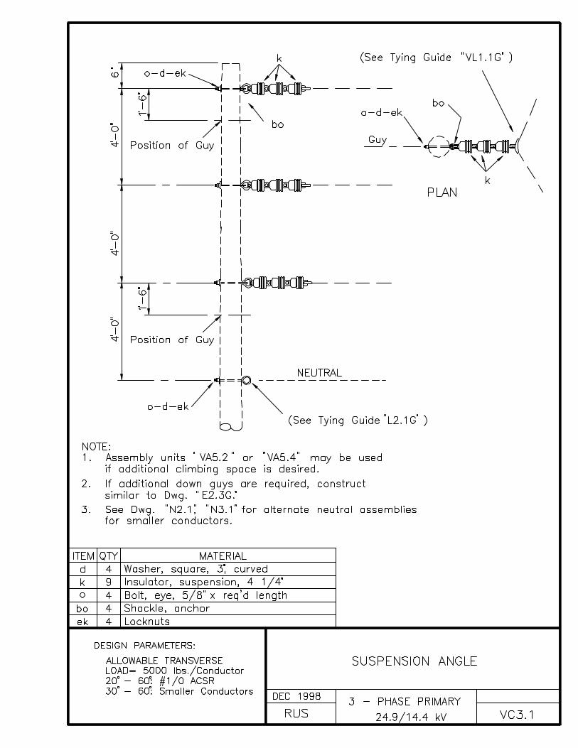
VC3.1 SUSPENSION ANGLE
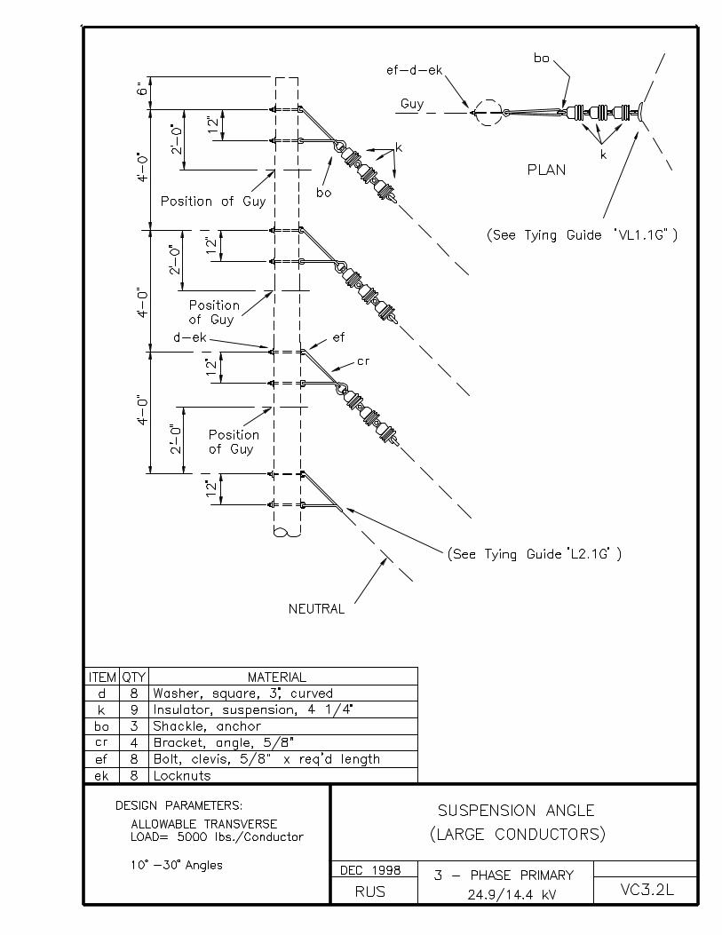
VC3.2L SUSPENSION ANGLE (LARGE CONDUCTORS)
VC4.1 DEADEND ANGLE (ACUTE)
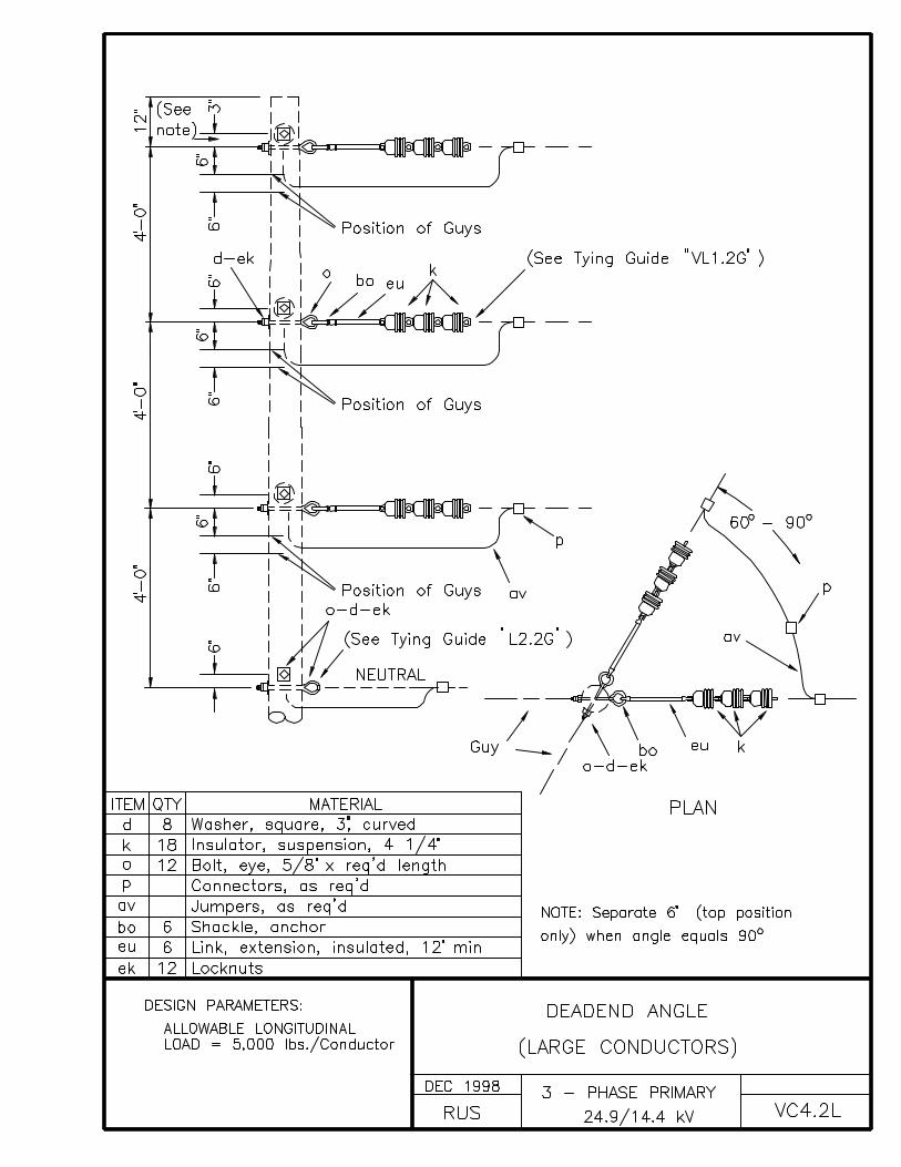
VC4.2L DEADEND ANGLE (LARGE CONDUCTORS)
VC5.1 SINGLE DEADEND - VERTICAL
VC5.2L SINGLE DEADEND - VERTICAL (LARGE CONDUCTORS)
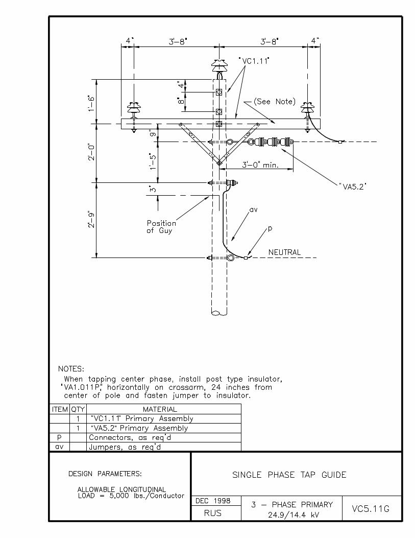
VC5.11G SINGLE PHASE TAP GUIDE
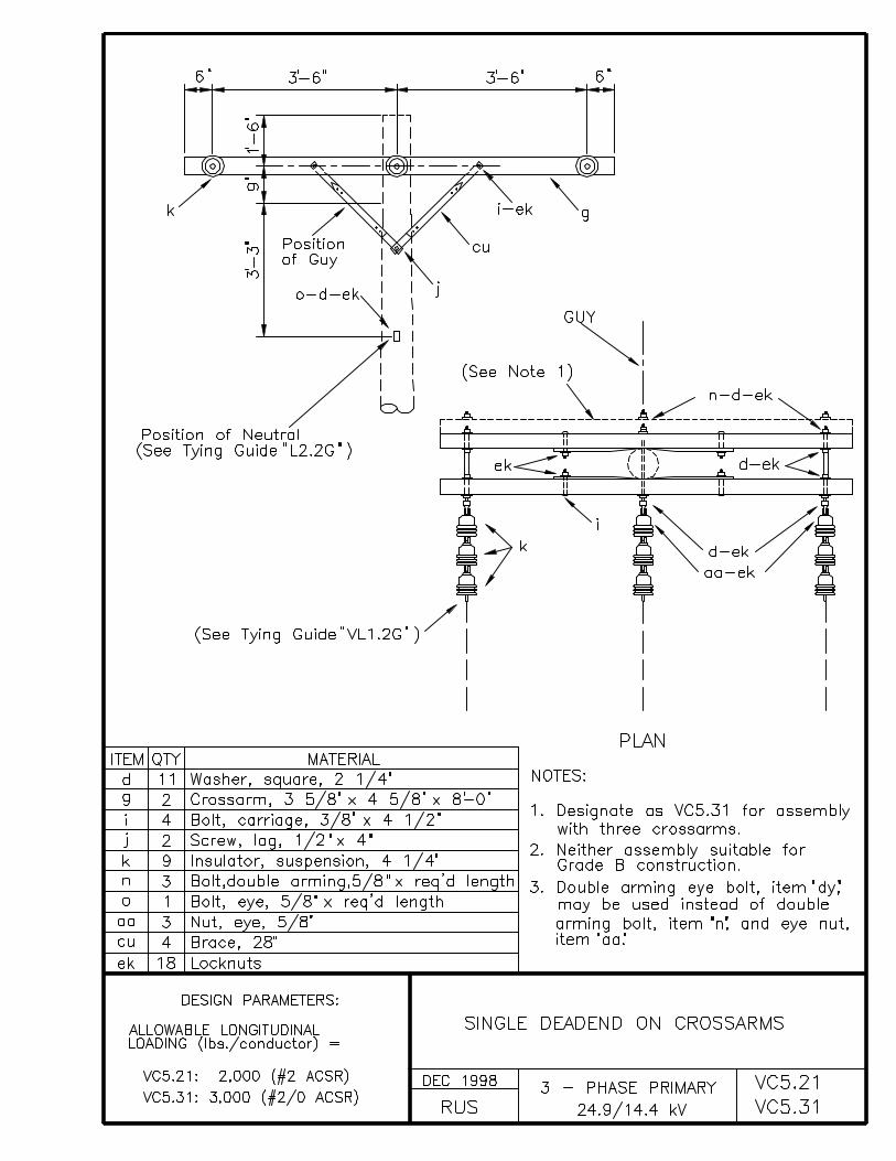
VC5.21, VC5.31 SINGLE DEADEND ON CROSSARMS
VC5.71L SINGLE DEADEND ON CROSSARM ASSEMBLY
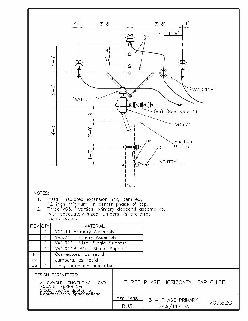
VC5.82G THREE PHASE HORIZONTAL TAP GUIDE
VC6.21, VC6.31 DOUBLE DEADEND ON CROSSARMS
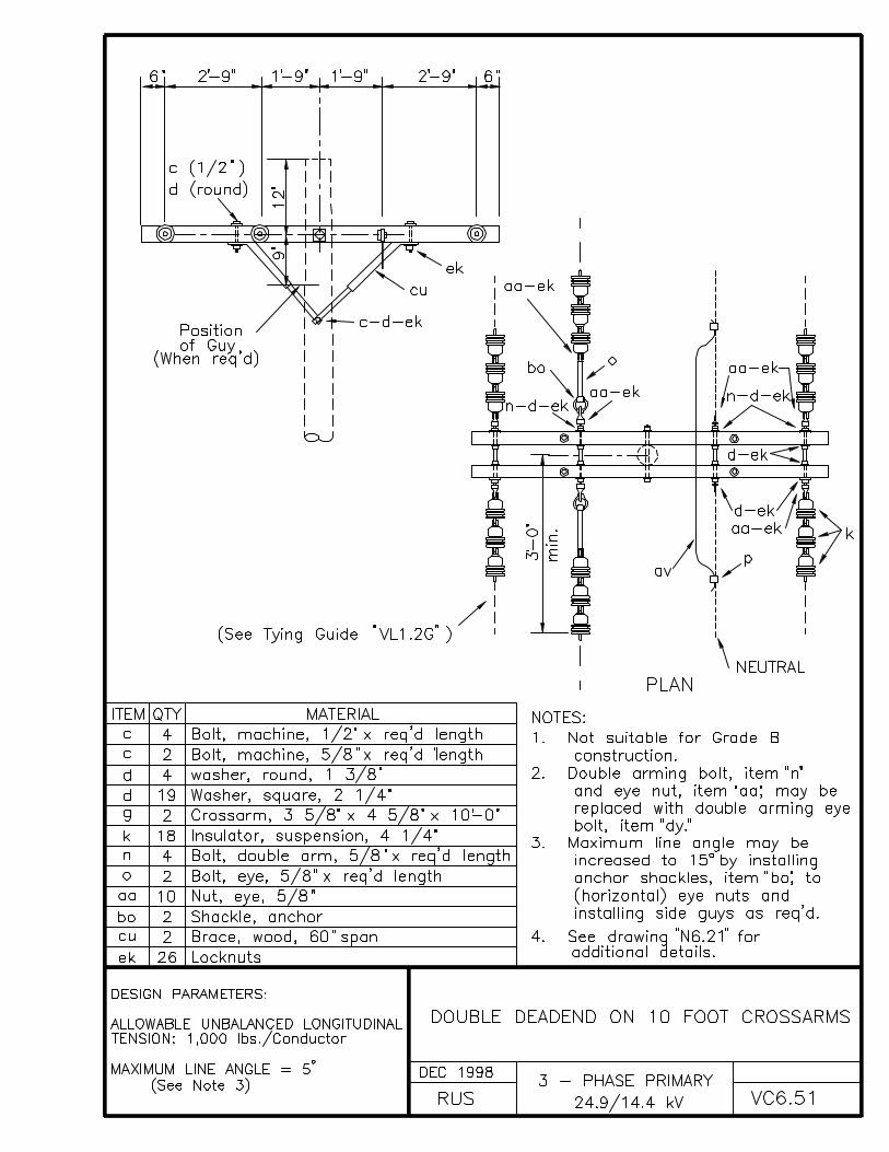
VC6.51 DOUBLE DEADEND ON 10 FOOT CROSSARMS
VC6.52G DOUBLE DEADEND ON 10 FOOT CROSSARMS(FEEDTHROUGH GUIDE)
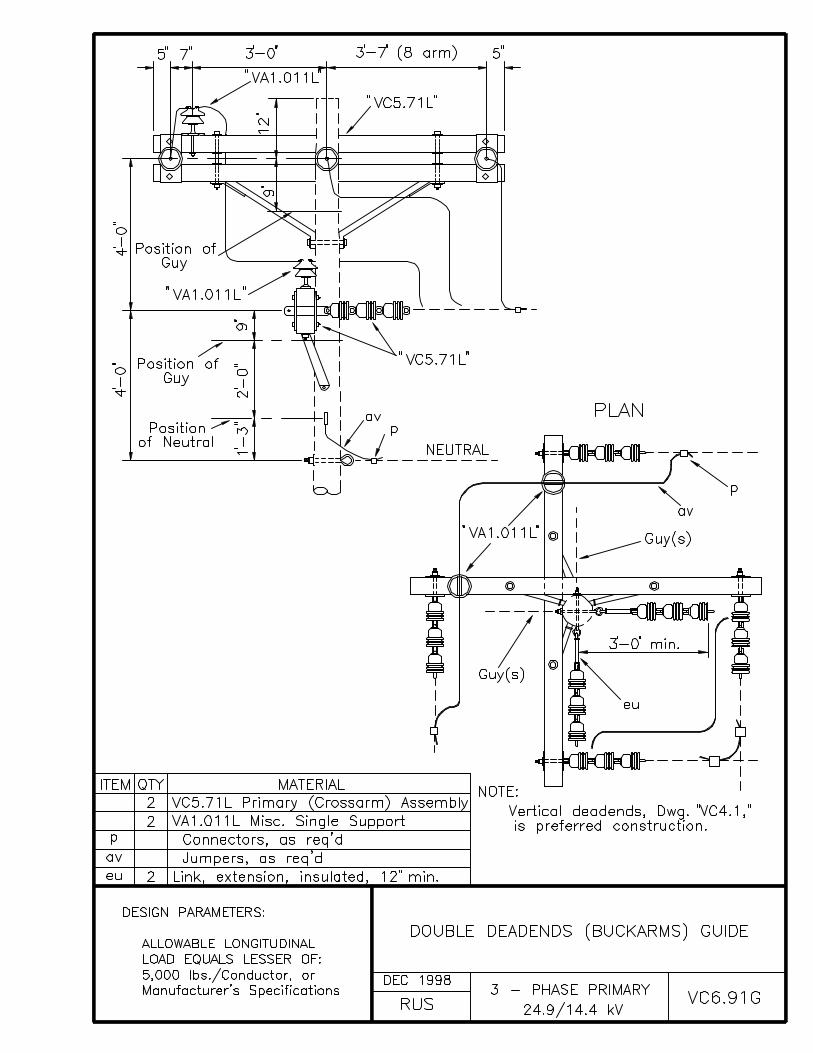
VC6.91G DOUBLE DEADENDS (BUCKARMS) GUIDE


INDEX D
DOUBLE CIRCUIT PRIMARY POLE TOP ASSEMBLY UNITS
DRAWING NUMBER DRAWING TITLE (DESCRIPTION)
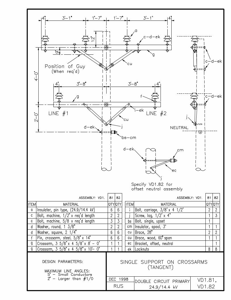
VD1.81, VD1.82 SINGLE SUPPORT ON CROSSARMS (TANGENT)
VD1.81L, VD1.82L SINGLE SUPPORT ON CROSSARMS (TANGENT) (LARGE CONDUCTORS)
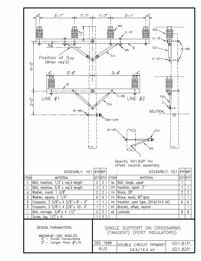
VD1.81P, VD1.82P SINGLE SUPPORT ON CROSSARMS (TANGENT) (POST INSULATORS)
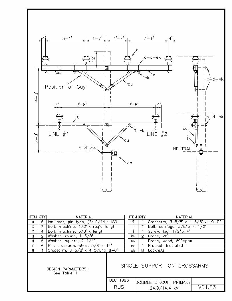
VD1.83 SINGLE SUPPORT ON CROSSARMS
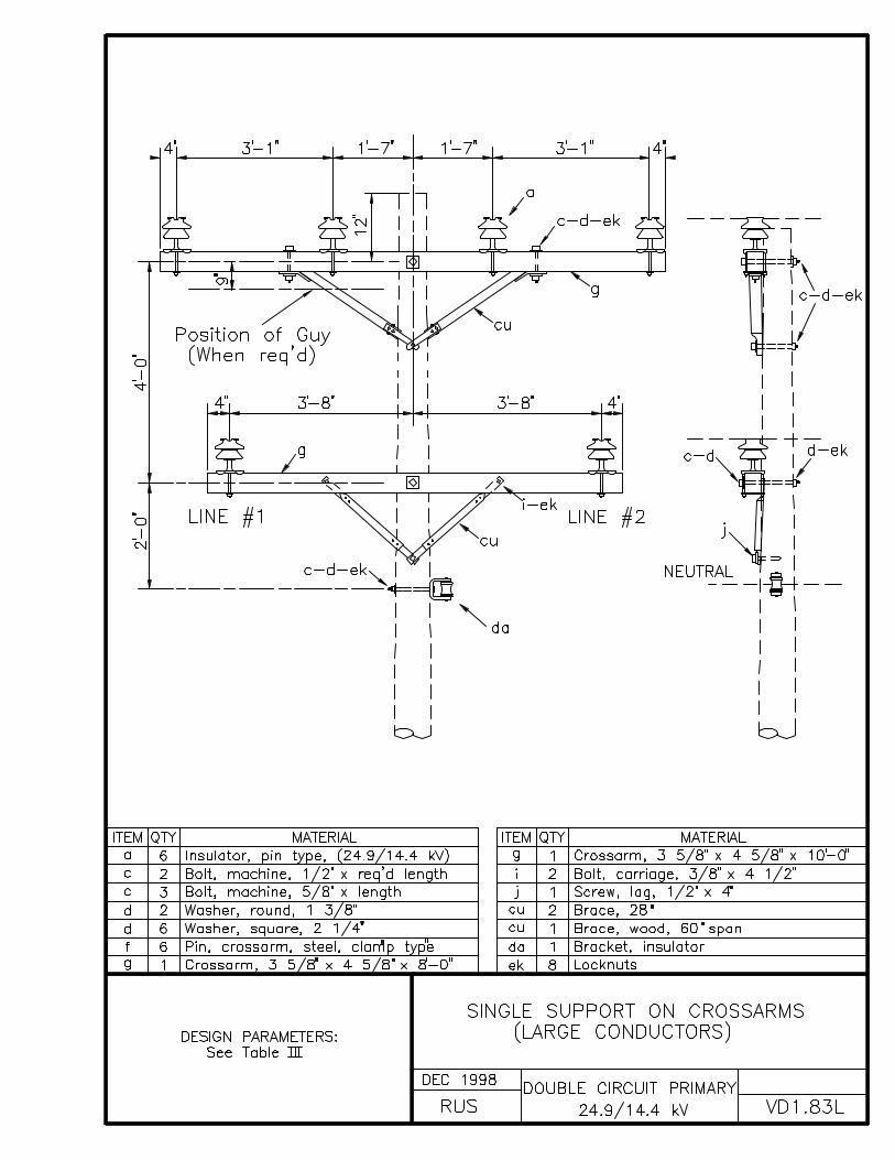
VD1.83L SINGLE SUPPORT ON CROSSARMS (LARGE CONDUCTORS)
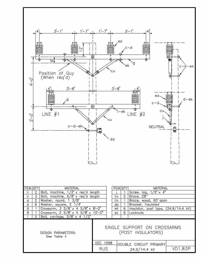
VD1.83P SINGLE SUPPORT ON CROSSARMS (POST INSULATORS)
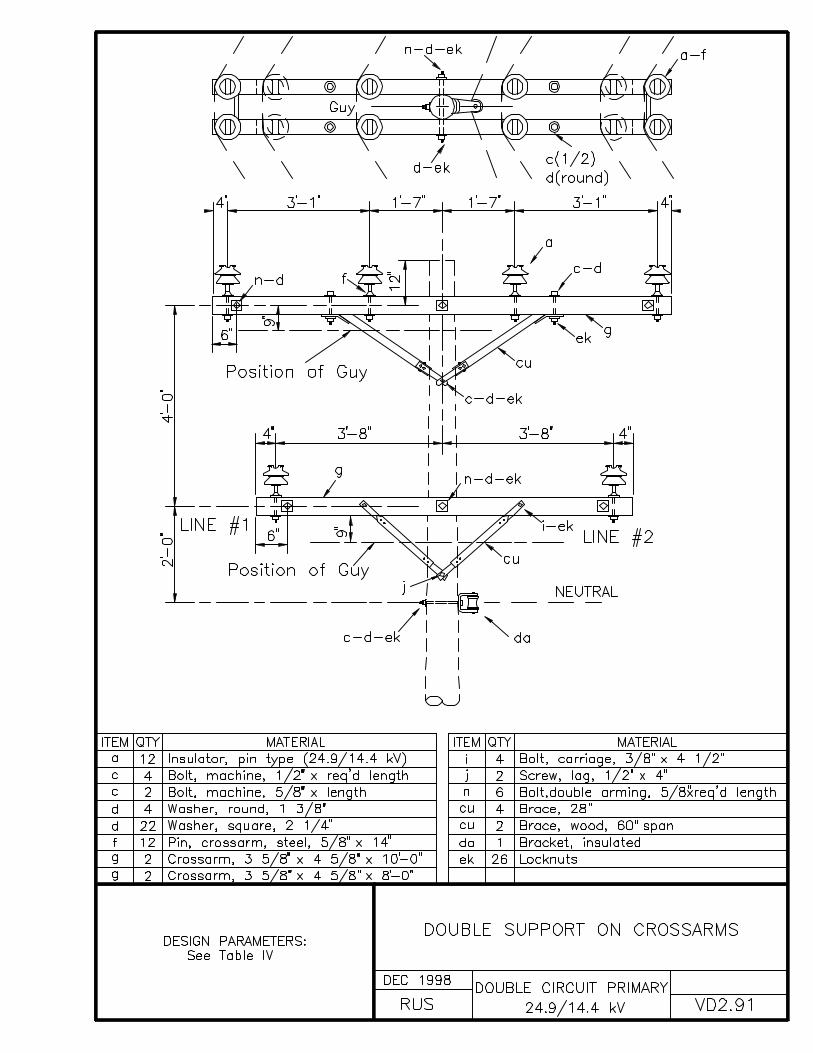
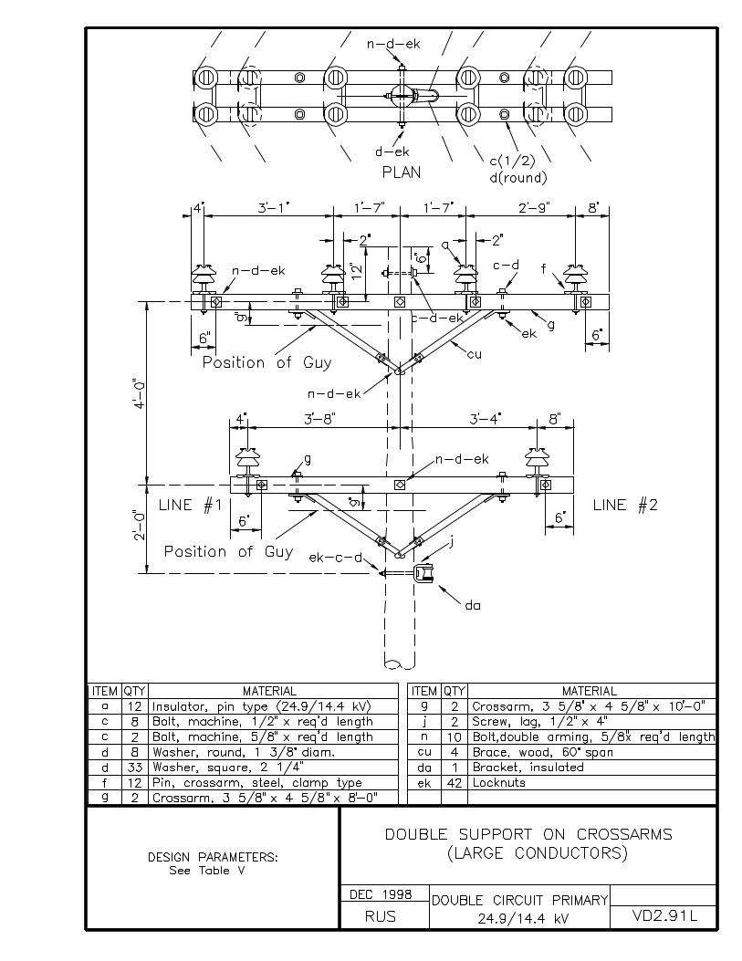
VD2.91 DOUBLE SUPPORT ON CROSSARMS
VD2.91L DOUBLE SUPPORT ON CROSSARMS (LARGE CONDUCTORS)
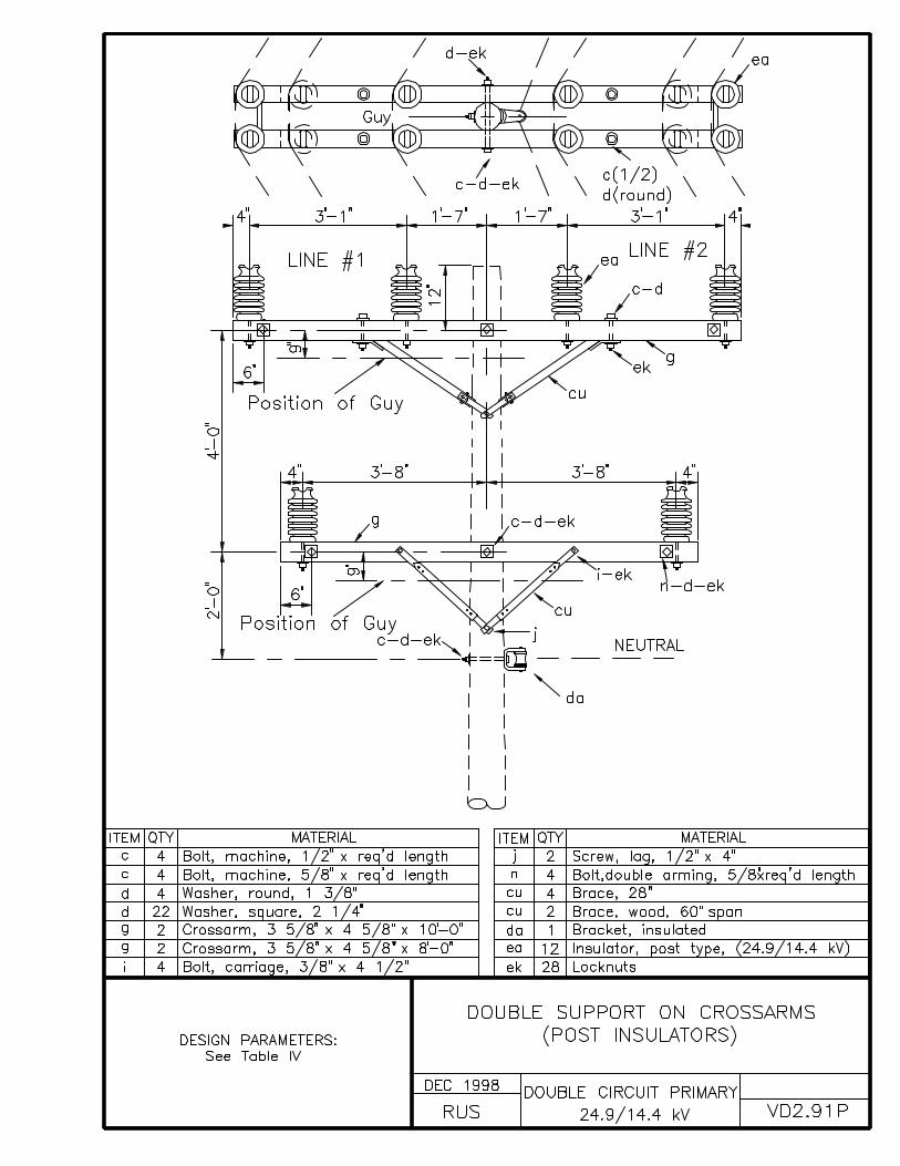
VD2.91P DOUBLE SUPPORT ON CROSSARMS (POST INSULATORS)
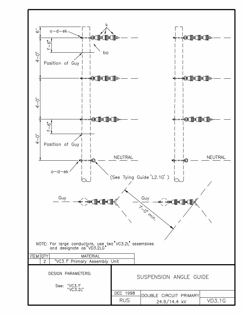
VD3.1G SUSPENSION ANGLE GUIDE
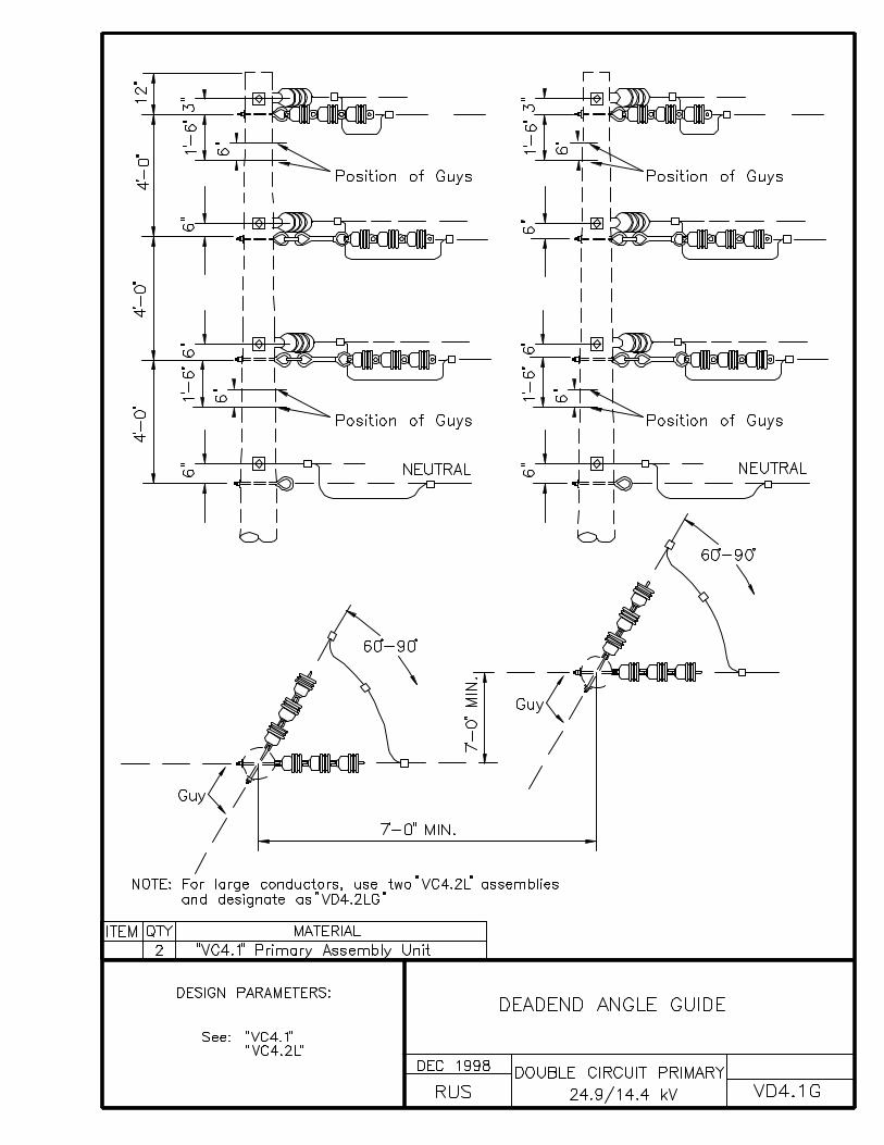
VD4.1G DEADEND ANGLE GUIDE
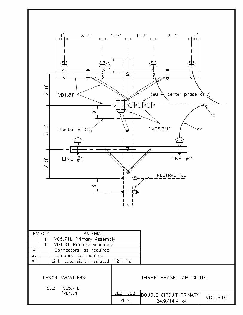
VD5.91G THREE PHASE TAP GUIDE
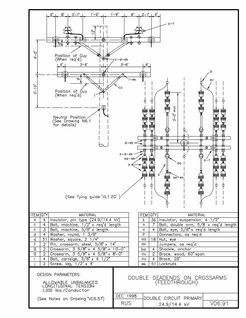
VD6.91 DOUBLE DEADENDS ON CROSSARMS (FEEDTHROUGH)

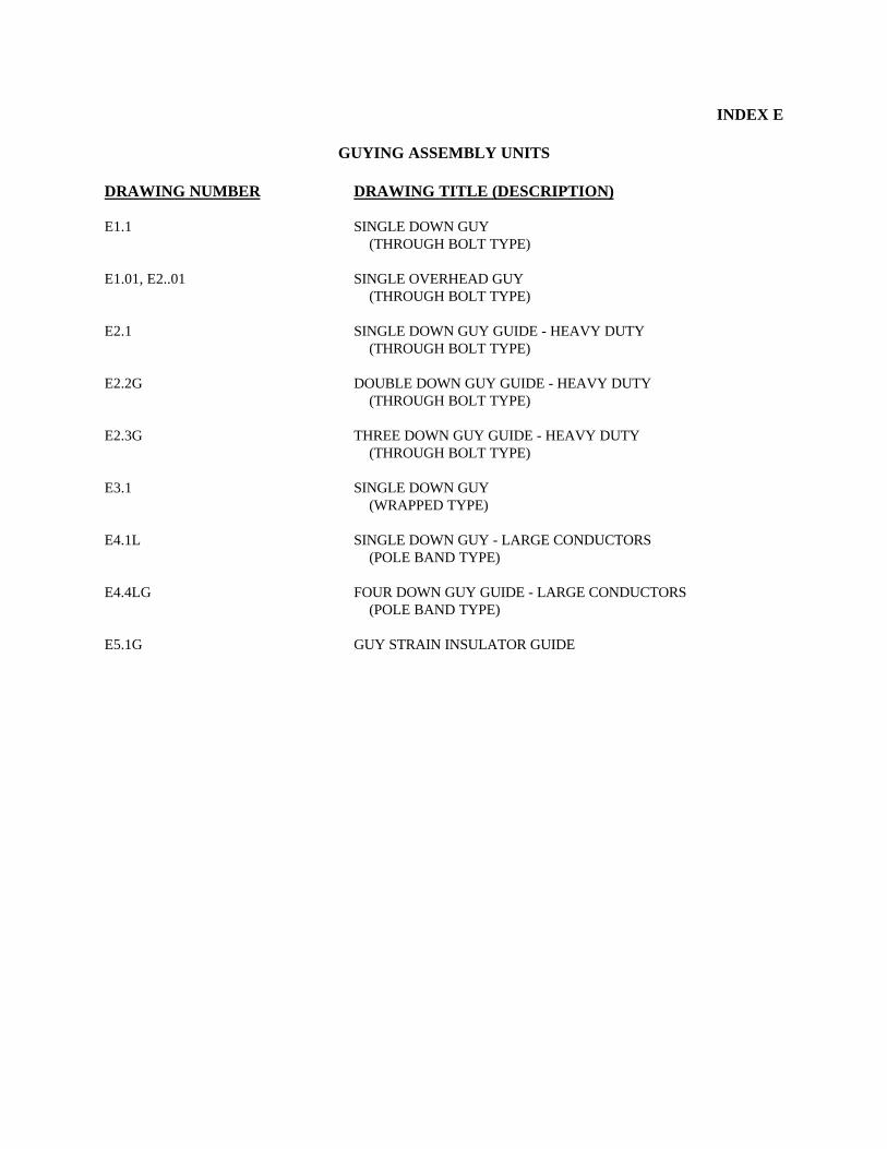
INDEX E
GUYING ASSEMBLY UNITS
DRAWING NUMBER DRAWING TITLE (DESCRIPTION)
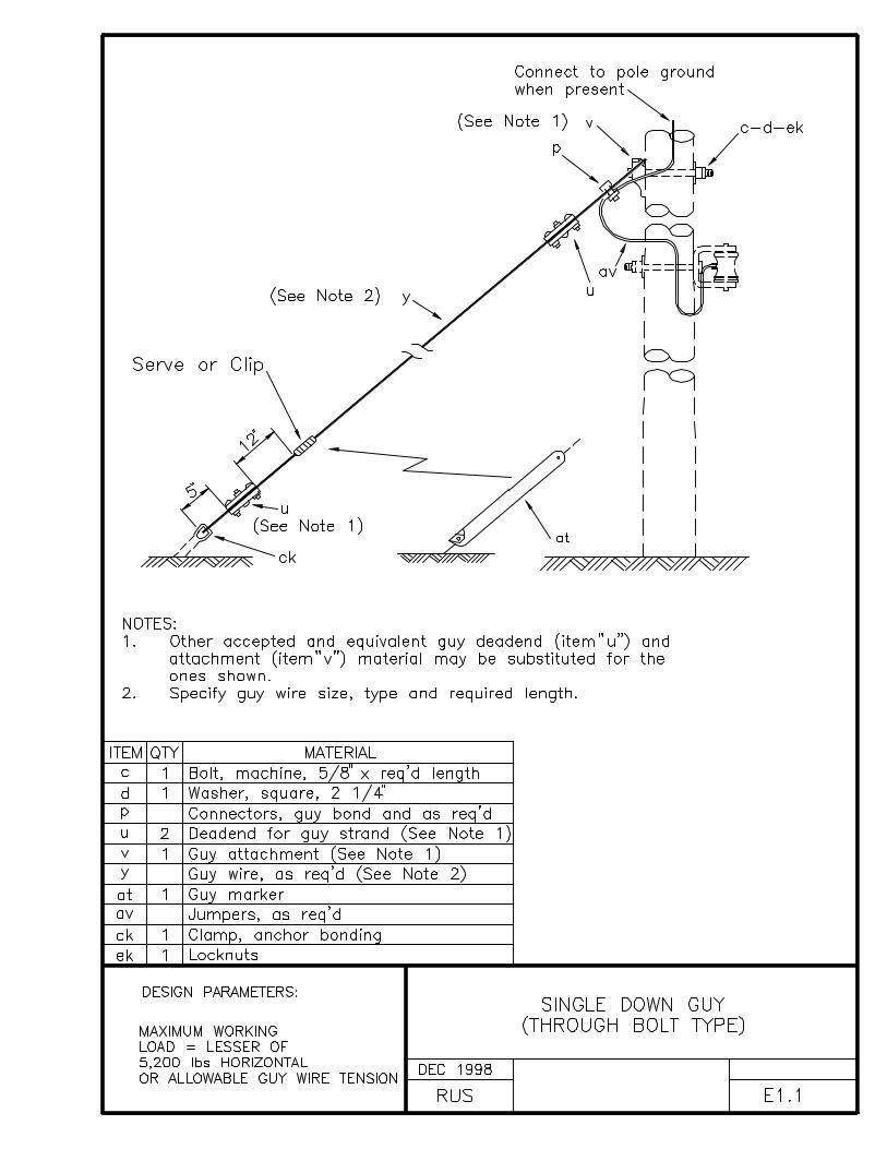
E1.1 SINGLE DOWN GUY (THROUGH BOLT TYPE)
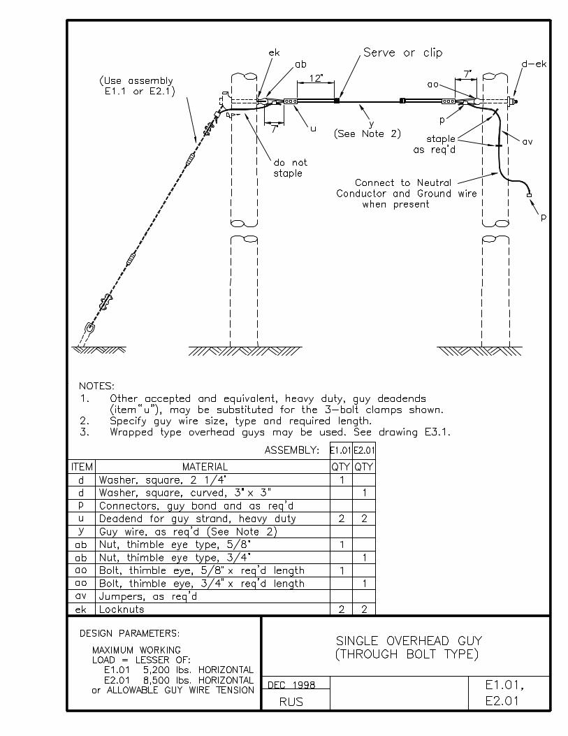
E1.01, E2..01 SINGLE OVERHEAD GUY (THROUGH BOLT TYPE)
E2.1 SINGLE DOWN GUY GUIDE - HEAVY DUTY (THROUGH BOLT TYPE)
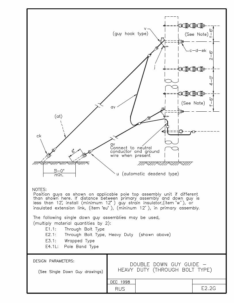
E2.2G DOUBLE DOWN GUY GUIDE - HEAVY DUTY (THROUGH BOLT TYPE)
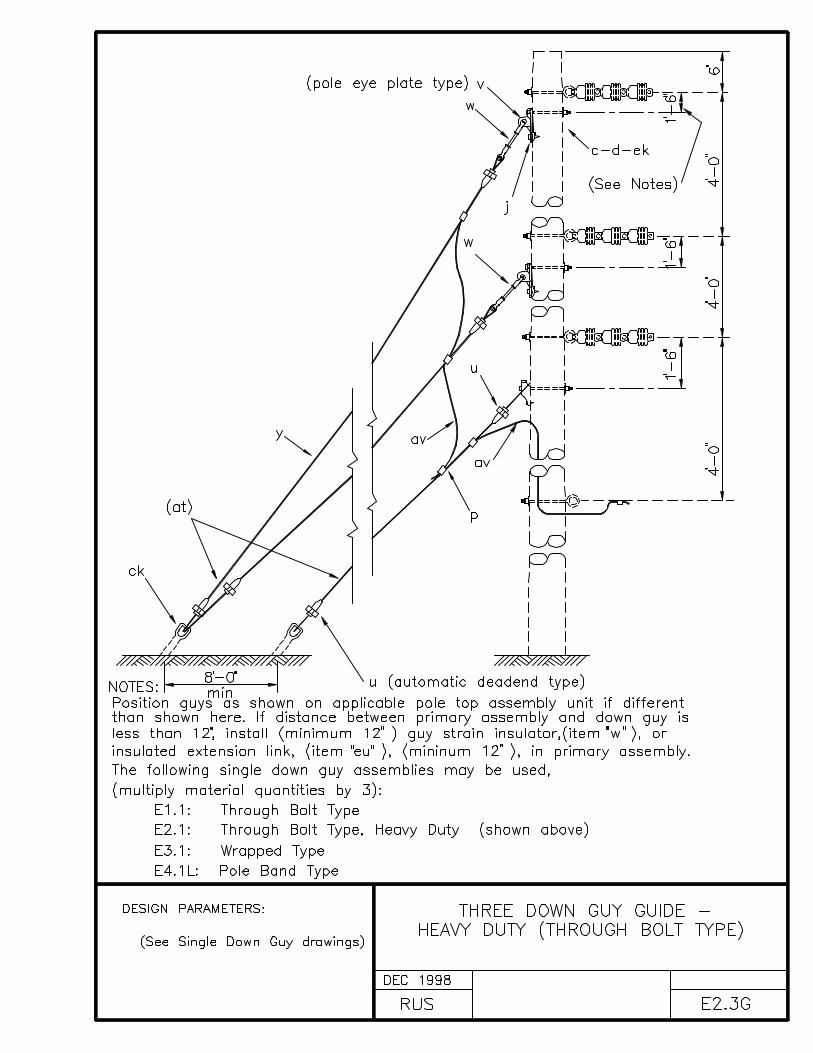
E2.3G THREE DOWN GUY GUIDE - HEAVY DUTY (THROUGH BOLT TYPE)
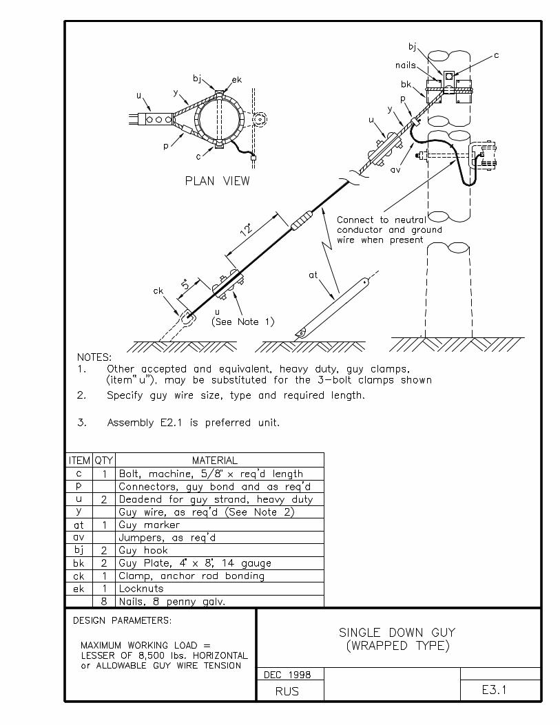
E3.1 SINGLE DOWN GUY (WRAPPED TYPE)
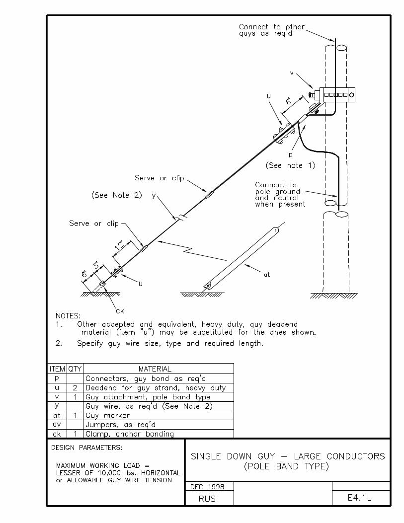
E4.1L SINGLE DOWN GUY - LARGE CONDUCTORS (POLE BAND TYPE)
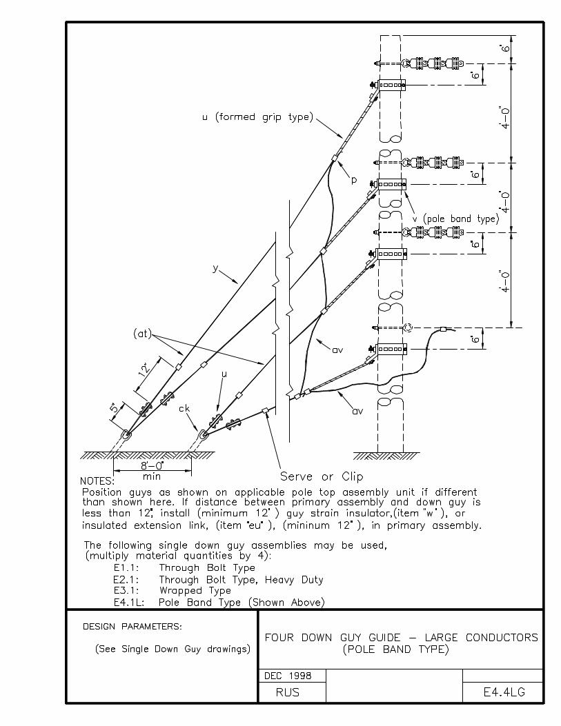
E4.4LG FOUR DOWN GUY GUIDE - LARGE CONDUCTORS (POLE BAND TYPE)
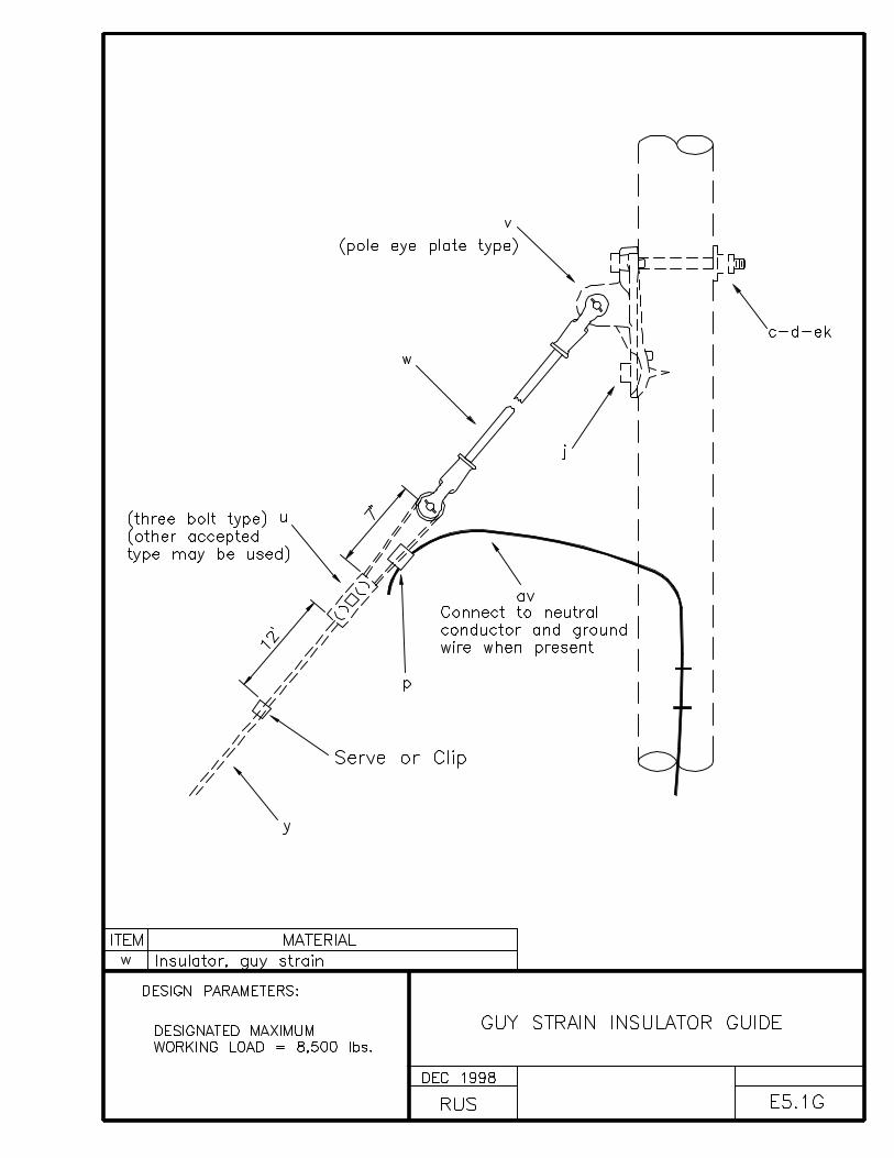
E5.1G GUY STRAIN INSULATOR GUIDE

CONSTRUCTION SPECIFICATIONS FOR GUYS
Guys shall be placed before the conductors are strung and shallbe attached to the pole as shown in the construction drawings.
The grade of construction of the guys shall be the same as thestructure or the highest grade required for any other conductorssupported by the pole or structure.
Deadend structure guys shall be installed in line with the pullof conductors as nearly as practical. Bisector guys at an anglestructure shall be installed as nearly as practical to the truebisector of the line angle.
A 1:1 slope for guy leads is recommended, especially on deadendstructures. Minimum guy leads are not recommended.
The applicable NESC safety factors have not been but must beapplied to determine the “allowable guy wire tension” as denotedin the design parameters of the guying assembly units.

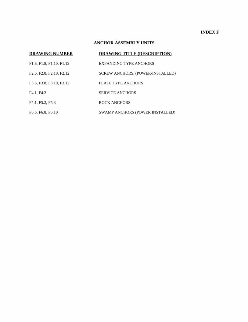
INDEX F
ANCHOR ASSEMBLY UNITS
DRAWING NUMBER DRAWING TITLE (DESCRIPTION)
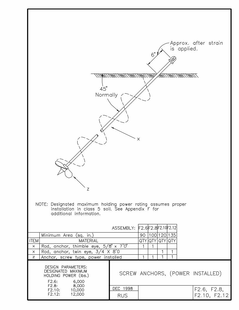
F1.6, F1.8, F1.10, F1.12 EXPANDING TYPE ANCHORS
F2.6, F2.8, F2.10, F2.12 SCREW ANCHORS, (POWER-INSTALLED)
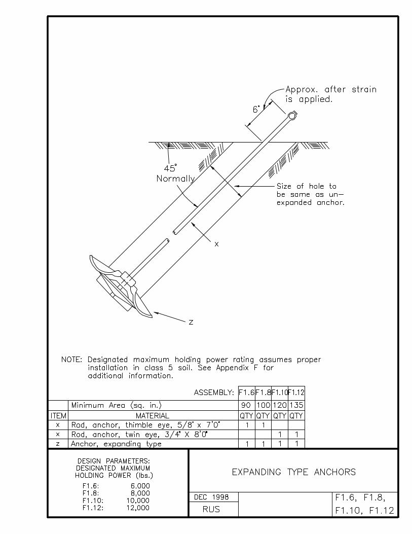
F3.6, F3.8, F3.10, F3.12 PLATE TYPE ANCHORS
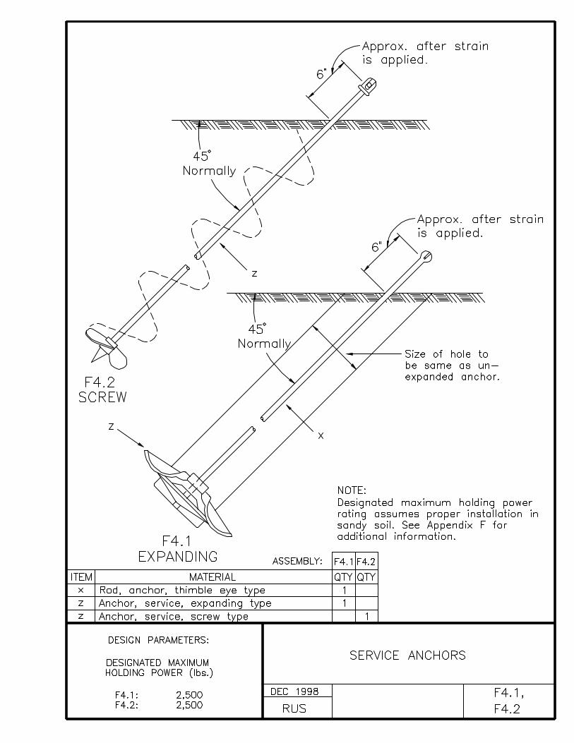
F4.1, F4.2 SERVICE ANCHORS
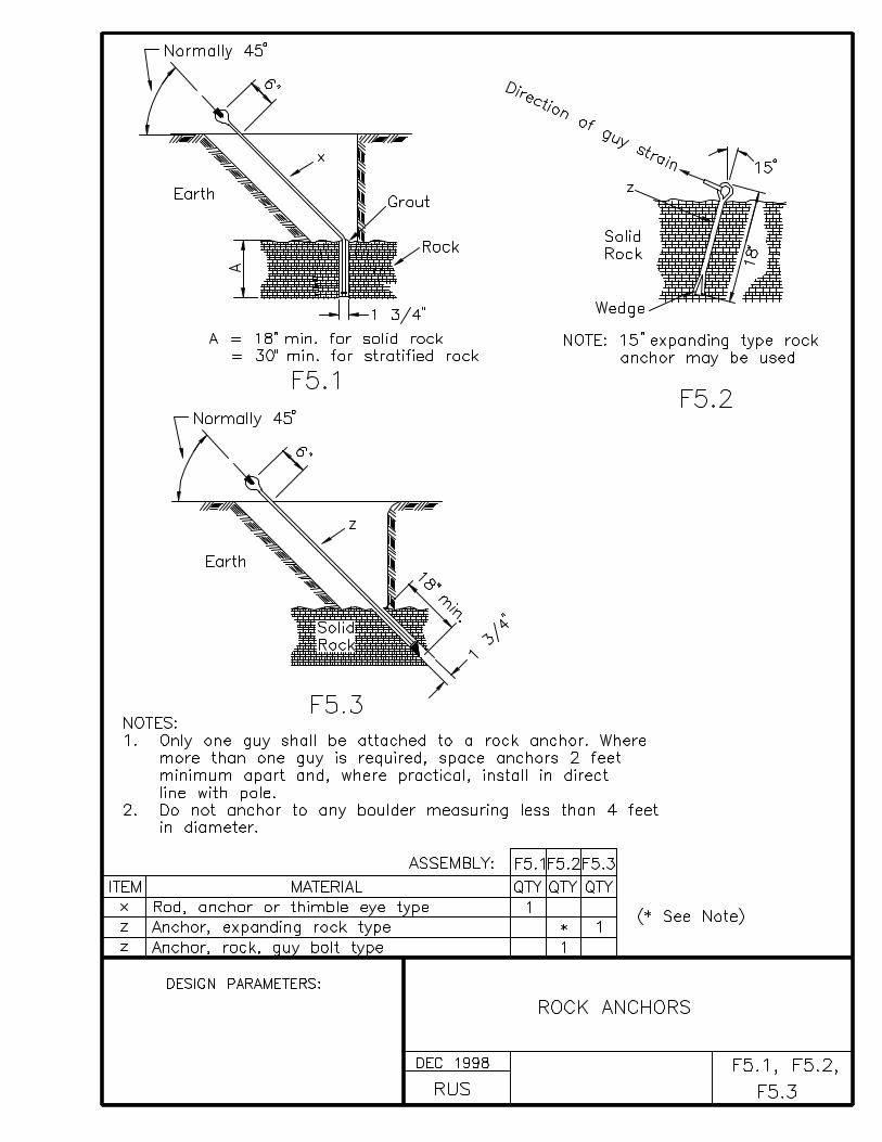
F5.1, F5.2, F5.3 ROCK ANCHORS
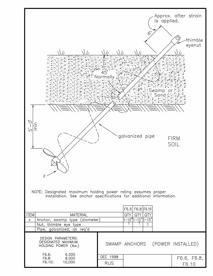
F6.6, F6.8, F6.10 SWAMP ANCHORS (POWER INSTALLED)
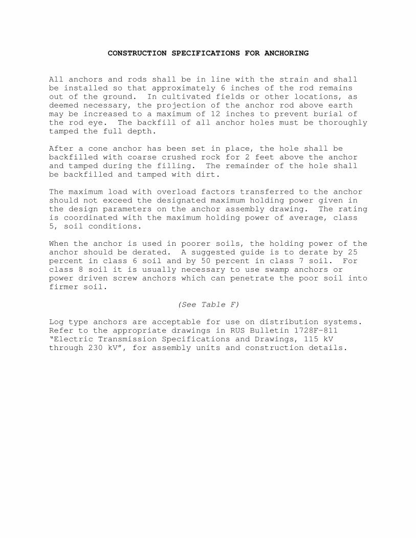
CONSTRUCTION SPECIFICATIONS FOR ANCHORING
All anchors and rods shall be in line with the strain and shallbe installed so that approximately 6 inches of the rod remainsout of the ground. In cultivated fields or other locations, asdeemed necessary, the projection of the anchor rod above earthmay be increased to a maximum of 12 inches to prevent burial ofthe rod eye. The backfill of all anchor holes must be thoroughlytamped the full depth.
After a cone anchor has been set in place, the hole shall bebackfilled with coarse crushed rock for 2 feet above the anchorand tamped during the filling. The remainder of the hole shallbe backfilled and tamped with dirt.
The maximum load with overload factors transferred to the anchorshould not exceed the designated maximum holding power given inthe design parameters on the anchor assembly drawing. The ratingis coordinated with the maximum holding power of average, class5, soil conditions.
When the anchor is used in poorer soils, the holding power of theanchor should be derated. A suggested guide is to derate by 25percent in class 6 soil and by 50 percent in class 7 soil. Forclass 8 soil it is usually necessary to use swamp anchors orpower driven screw anchors which can penetrate the poor soil intofirmer soil.
(See Table F)
Log type anchors are acceptable for use on distribution systems.Refer to the appropriate drawings in RUS Bulletin 1728F-811“Electric Transmission Specifications and Drawings, 115 kVthrough 230 kV”, for assembly units and construction details.

TABLE F
Soil Classifications
CLASS ENGINEERING DESCRIPTION
0 Sound hard rock, unweatherd
1 Very dense and/or cemented sands;coarse gravel and cobbles
2 Dense fine sand; very hard silts andclays (may be preloaded)
3 Dense clayed sand sand gravel;very stiff to hard silts and clays
4 Medium dense sandy gravel; very stiffto hard silts and clays
5 Medium dense coarse sand and sandy gravels;stiff to very stiff silts and clays
6 Loose to medium dense fine to coarse sand;firm to stiff clays and silts
7 Loose fine sand; alluvium; loess;soft-firm clays; varved clays; fill
8 Peat; organic silts; inundated silts; fly ash
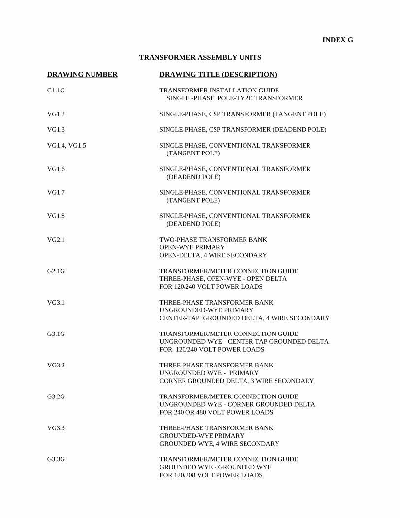
INDEX G
TRANSFORMER ASSEMBLY UNITS
DRAWING NUMBER DRAWING TITLE (DESCRIPTION)
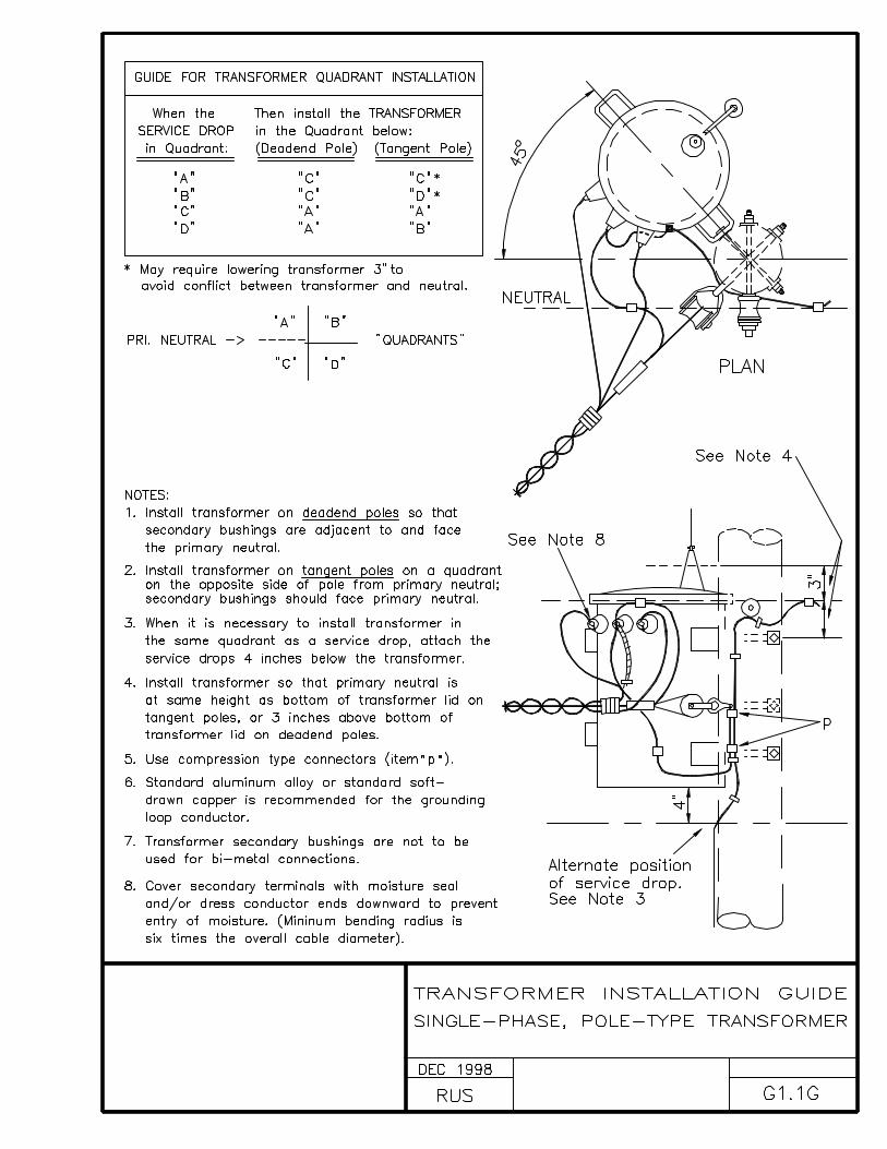
G1.1G TRANSFORMER INSTALLATION GUIDE SINGLE -PHASE, POLE-TYPE TRANSFORMER
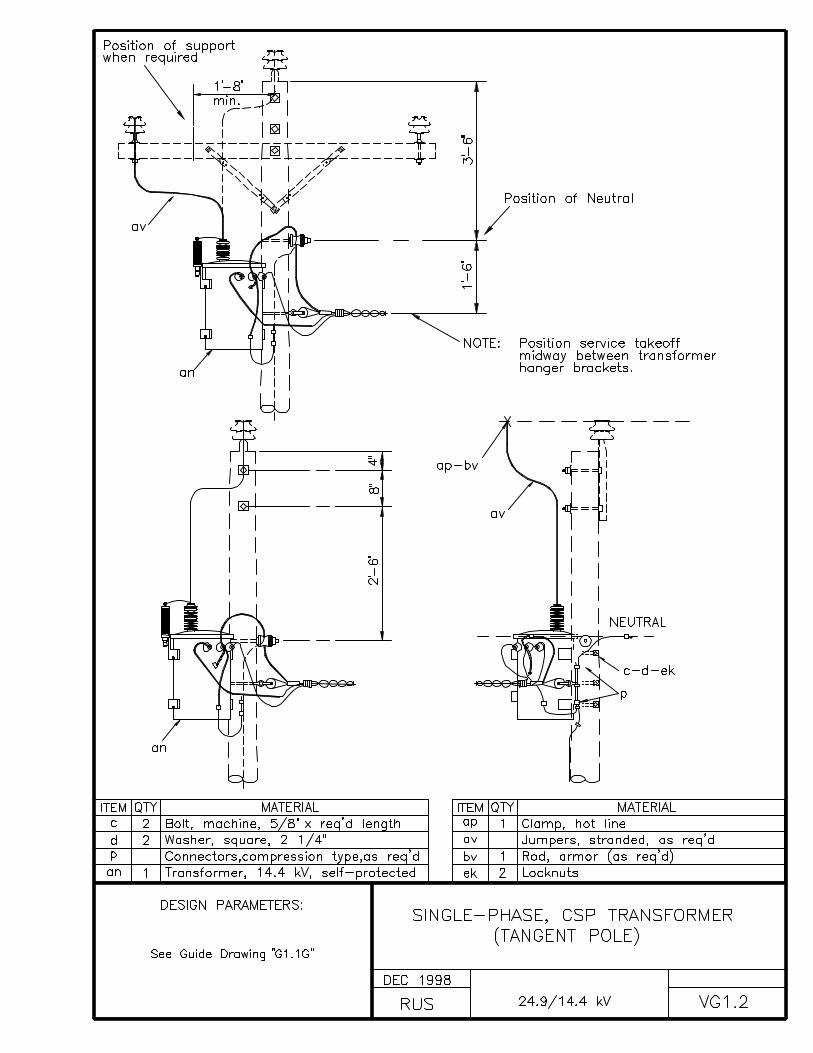
VG1.2 SINGLE-PHASE, CSP TRANSFORMER (TANGENT POLE)
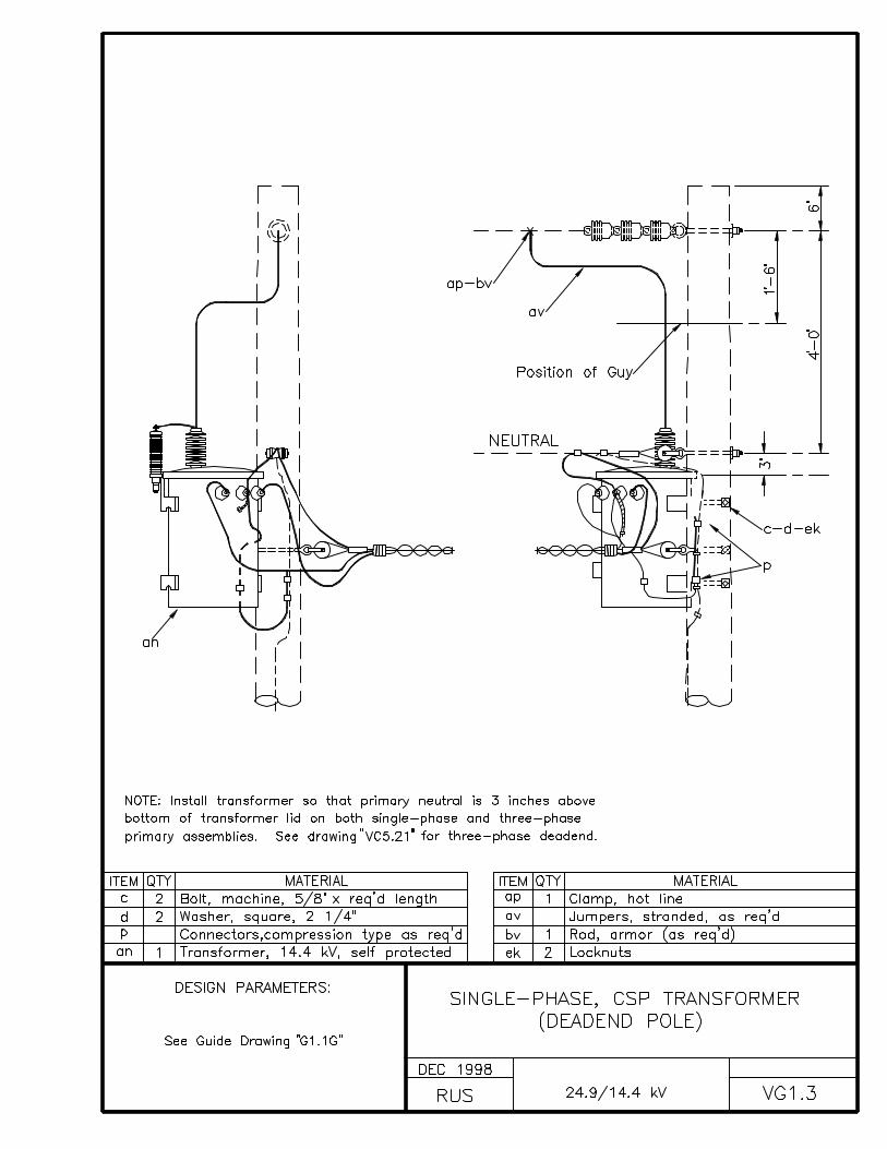
VG1.3 SINGLE-PHASE, CSP TRANSFORMER (DEADEND POLE)
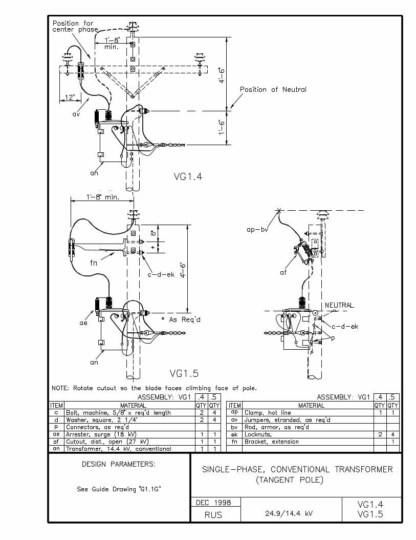
VG1.4, VG1.5 SINGLE-PHASE, CONVENTIONAL TRANSFORMER (TANGENT POLE)
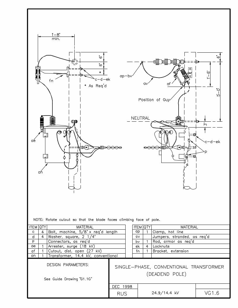
VG1.6 SINGLE-PHASE, CONVENTIONAL TRANSFORMER (DEADEND POLE)
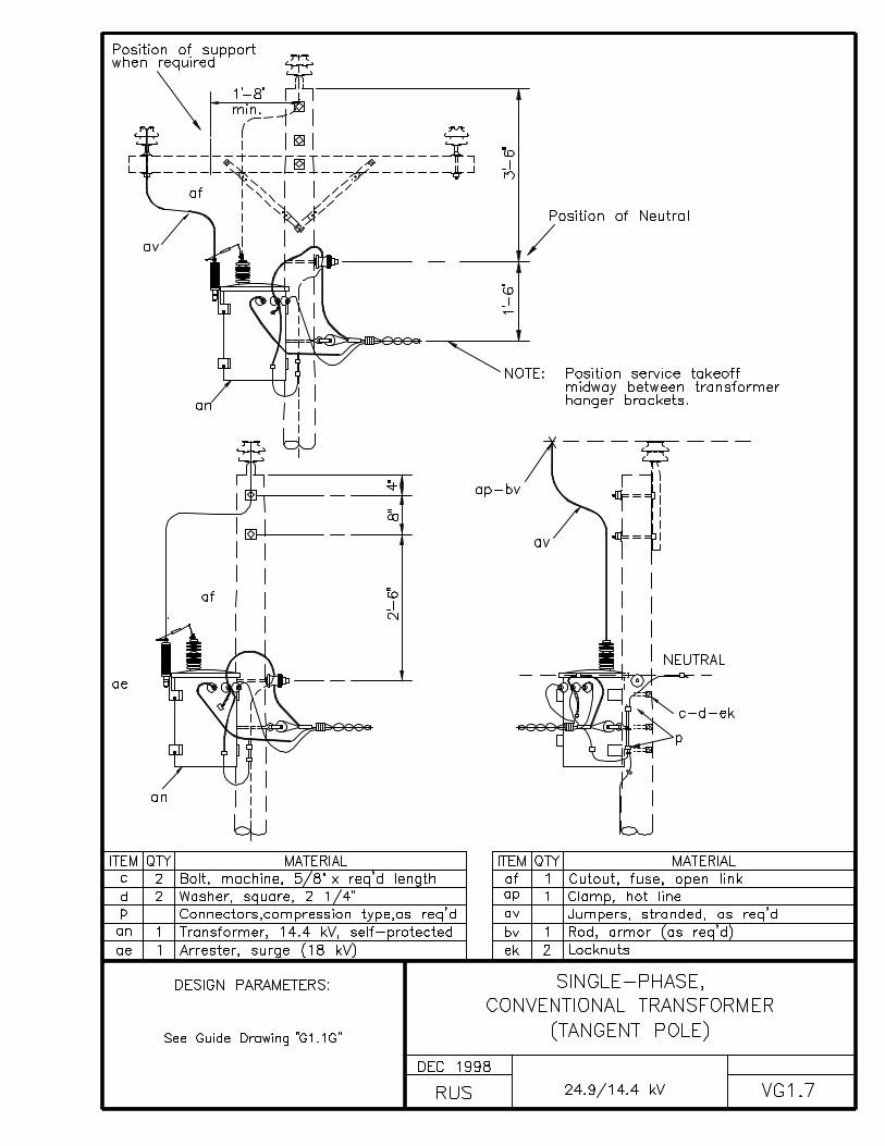
VG1.7 SINGLE-PHASE, CONVENTIONAL TRANSFORMER (TANGENT POLE)
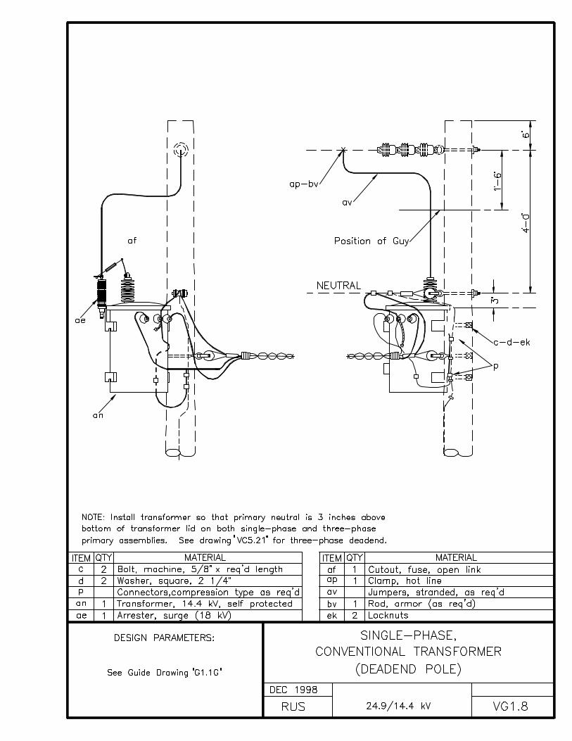
VG1.8 SINGLE-PHASE, CONVENTIONAL TRANSFORMER (DEADEND POLE)
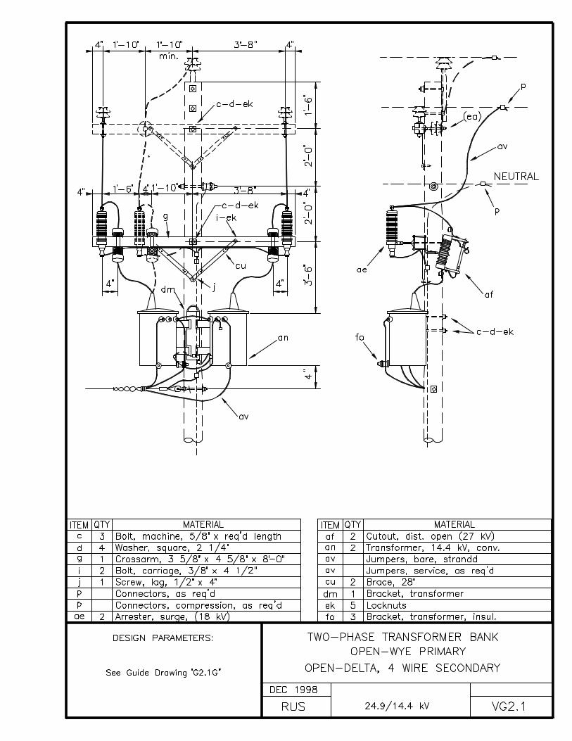
VG2.1 TWO-PHASE TRANSFORMER BANKOPEN-WYE PRIMARYOPEN-DELTA, 4 WIRE SECONDARY
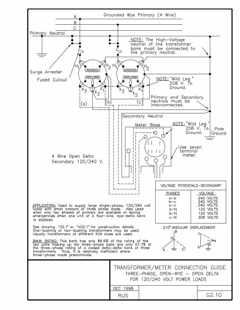
G2.1G TRANSFORMER/METER CONNECTION GUIDETHREE-PHASE, OPEN-WYE - OPEN DELTAFOR 120/240 VOLT POWER LOADS
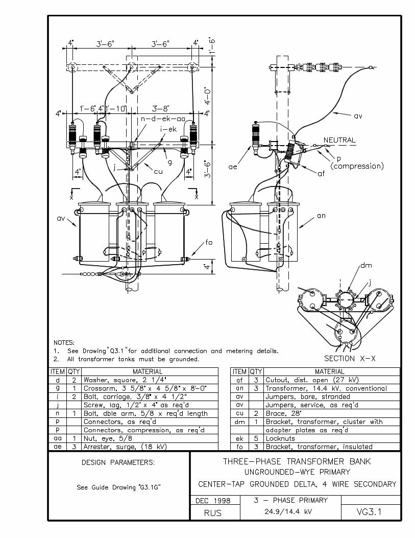
VG3.1 THREE-PHASE TRANSFORMER BANKUNGROUNDED-WYE PRIMARYCENTER-TAP GROUNDED DELTA, 4 WIRE SECONDARY
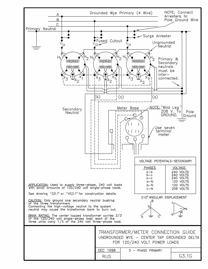
G3.1G TRANSFORMER/METER CONNECTION GUIDEUNGROUNDED WYE - CENTER TAP GROUNDED DELTAFOR 120/240 VOLT POWER LOADS
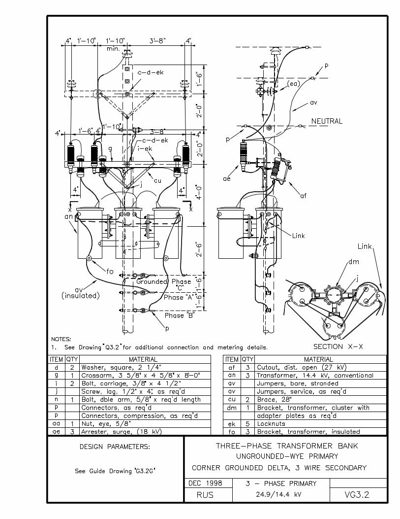
VG3.2 THREE-PHASE TRANSFORMER BANKUNGROUNDED WYE - PRIMARYCORNER GROUNDED DELTA, 3 WIRE SECONDARY
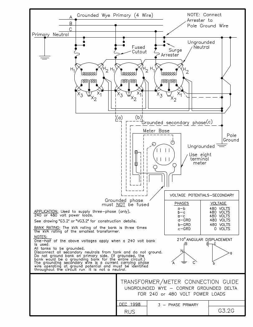
G3.2G TRANSFORMER/METER CONNECTION GUIDEUNGROUNDED WYE - CORNER GROUNDED DELTAFOR 240 OR 480 VOLT POWER LOADS
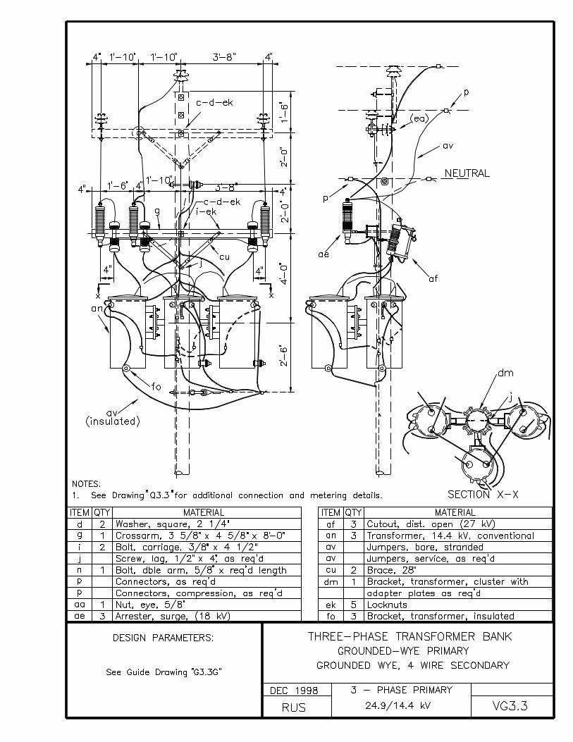
VG3.3 THREE-PHASE TRANSFORMER BANKGROUNDED-WYE PRIMARYGROUNDED WYE, 4 WIRE SECONDARY
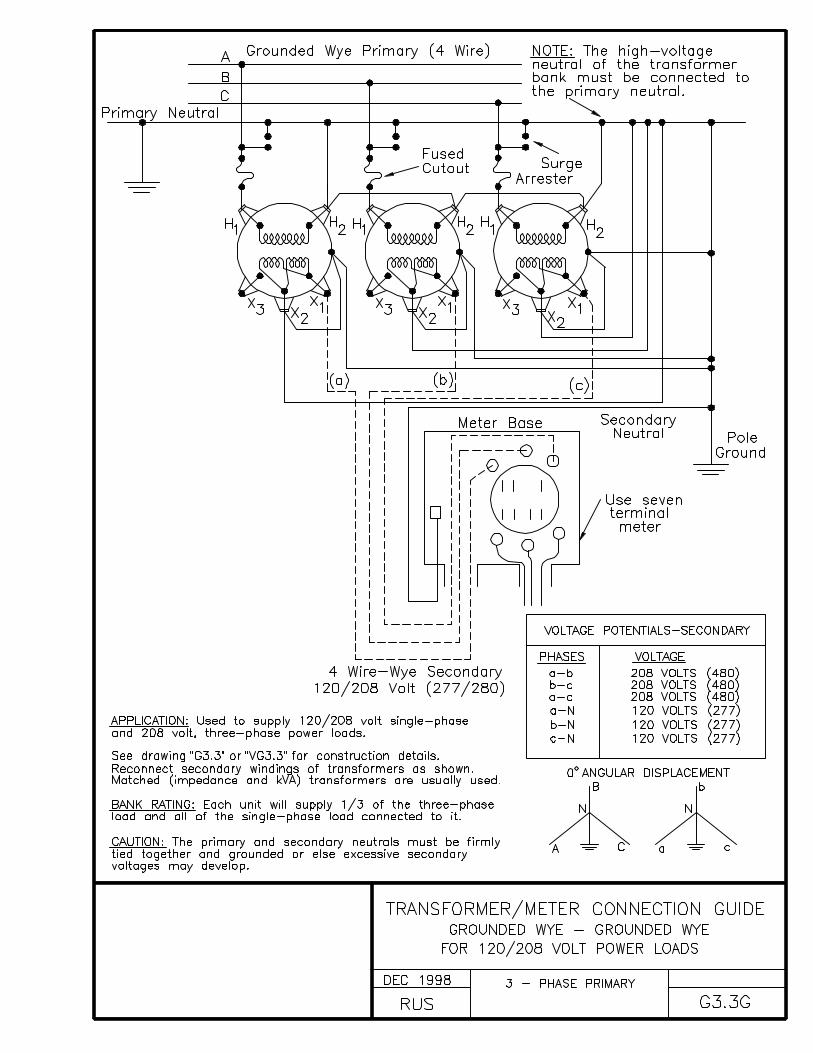
G3.3G TRANSFORMER/METER CONNECTION GUIDEGROUNDED WYE - GROUNDED WYEFOR 120/208 VOLT POWER LOADS
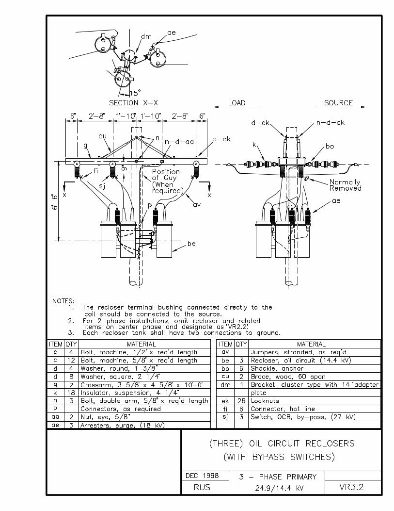
CONSTRUCTION SPECIFICATIONS FOR TAPS, JUMPERS, AND ARRESTERS
Jumpers and other leads connected to line conductors shall havesufficient slack to allow free movement of the conductors. Whereslack is not shown on the construction drawings, it will beprovided by at least two (2) bends in a vertical plane, or one(1) in a horizontal plane, or the equivalent. In areas whereaeolian vibration occurs, special measures to minimize theeffects of jumper breaks shall be used as may be specified.
All leads on equipment, such as transformers, reclosers, etc.,shall be a minimum of #6 copper conductivity. Where aluminumjumpers are used, a connection to an unplated bronze terminalshall be made by splicing a short stub of copper to the aluminumjumpers using a compression connector suitable for the bimetallicconnection.
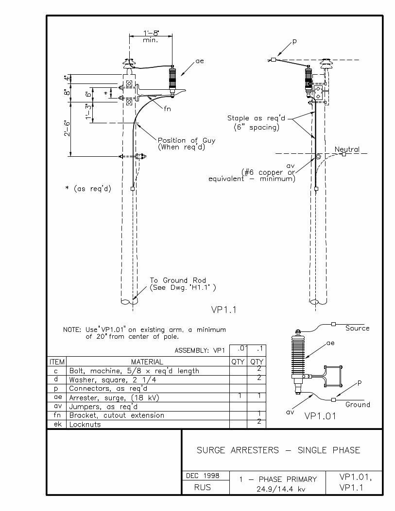
Where applicable, the external gap electrodes of surge arresters,combination arrester cutout units, and transformers mountedarresters shall be adjusted to the manufacturer’s recommendedspacing. Care shall be taken so that the adjusted gap is notdisturbed when the equipment is installed.
It may be necessary, and is permissible, to lower the neutralattachment on standard construction pole top assemblies anadditional distance not exceeding 2 feet to provide adequateclearance between cutout and single-phase, conventionaldistribution transformers.
INDEX H
GROUNDING ASSEMBLY UNITS
DRAWING NUMBER DRAWING TITLE (DESCRIPTION)
H1.1 GROUNDING ASSEMBLY - GROUND ROD TYPE
H2.1 GROUNDING ASSEMBLY - TRENCH TYPE
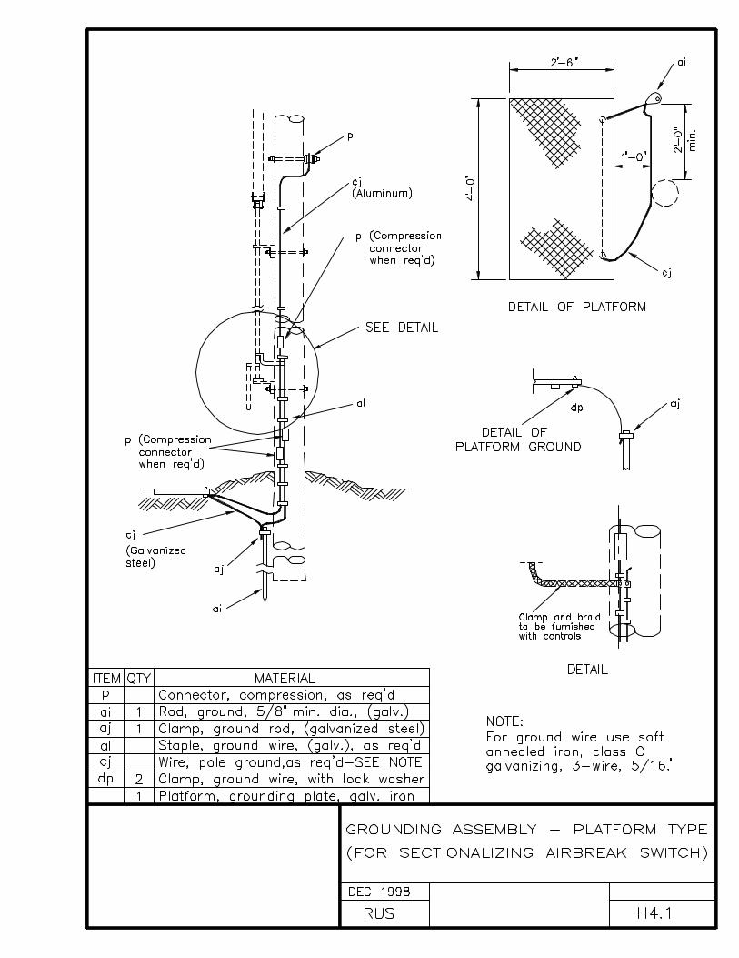
H3.1 GROUNDING ASSEMBLY - GROUND ROD TYPE(FOR SECTIONALIZING AIRBREAK SWITCH)
H4.1 GROUNDING ASSEMBLY - PLATFORM TYPE(FOR SECTIONALIZING AIRBREAK SWITCH)
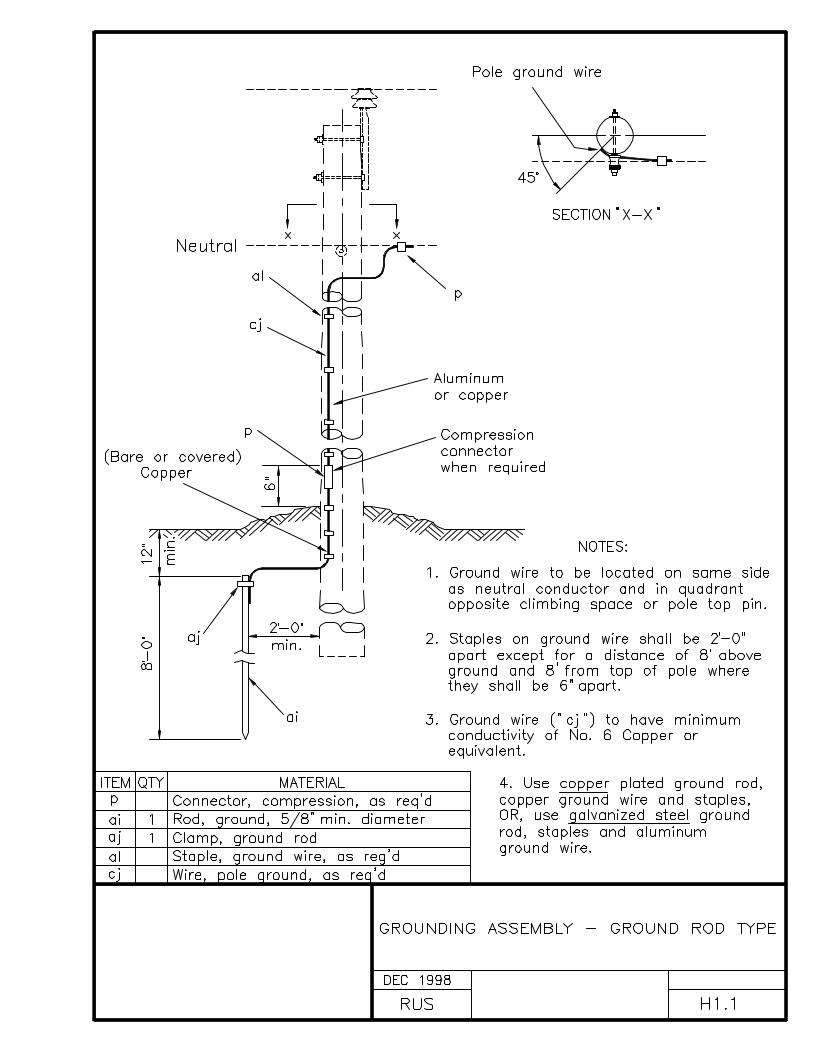
CONSTRUCTION SPECIFICATIONS FOR GROUNDING
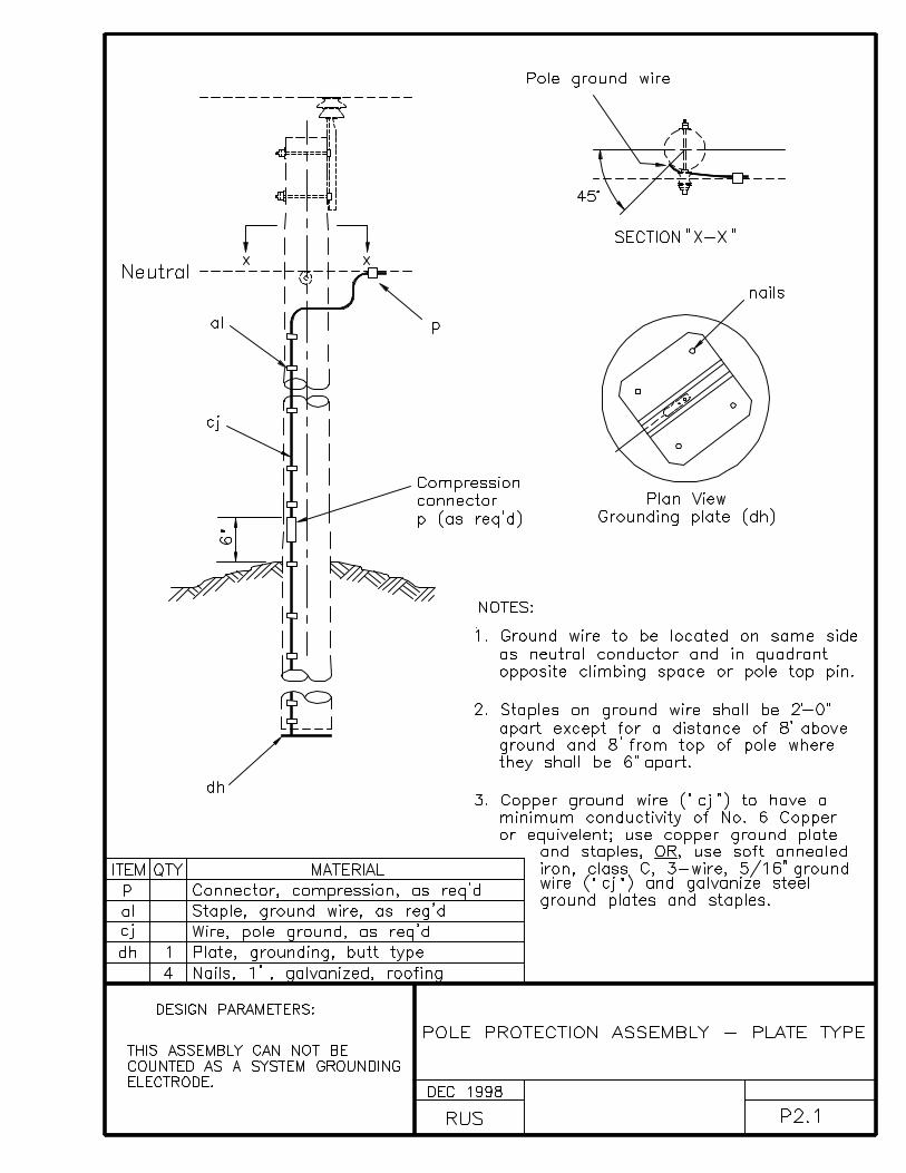
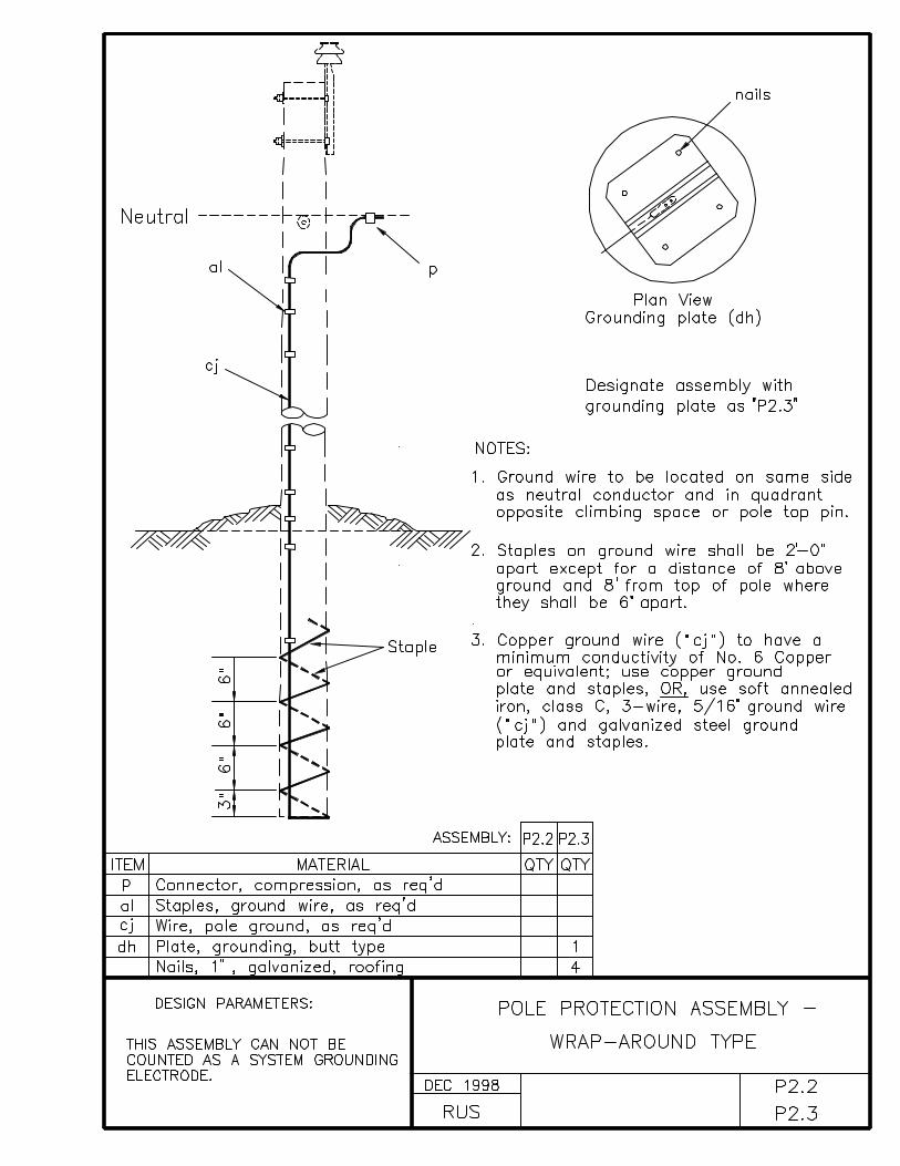
Ground rods shall be driven full length in undisturbed earth inaccordance with the construction drawings. They shall beinstalled a minimum of 2 feet from the face of the pole. The topof the ground rods shall be at least 12 inches below the surfaceof the earth. The ground wire shall be attached to the rod withan appropriate ground rod clamp and shall be secured to the polewith staples. The staples on the ground wire shall be spaced 2feet part, except for a distance of 8 feet above the ground and 8feet down from the top of the pole, as applicable, where theyshall be 6 inches apart.
The connection between the ground rod and the system neutralshould be made by one continuous piece of conductor, (the poleground wire), and installed in the shortest and most direct pathaccording to the construction drawings. If a splice is required,it shall be made using a compression type connector. Such asplice shall only be installed a minimum of 6 inches above theground line. The pole ground wire shall be connected to thesystem neutral using a compression type connector.
All equipment shall have at least 2 connections from the frame,case, or tank to the multi-grounded system neutral conductor.The pole ground wire may be used for one or both of theseconnections.
All neutral conductors on the pole shall be connected directly toeach other, and connected to the pole ground wire if present.Ground connections, in addition to the ones required andspecified herein, are acceptable unless they add undue congestionon the structure.
All equipment ground wires, neutral conductors, downguys,messenger wires, and surge-protection ground wires shall beinterconnected and attached to a common (pole) ground wire inaccordance with the requirements of, or exempted by, the NationalElectrical Safety Code.


INDEX J
SECONDARY ASSEMBLY UNITS
DRAWING NUMBER DRAWING TITLE (DESCRIPTION)
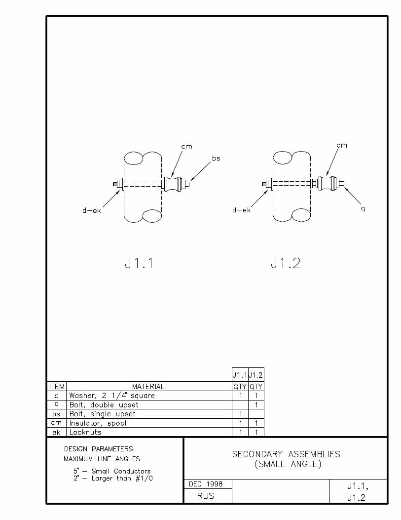
J1.1, J1.2 SECONDARY ASSEMBLIES (SMALL ANGLE)
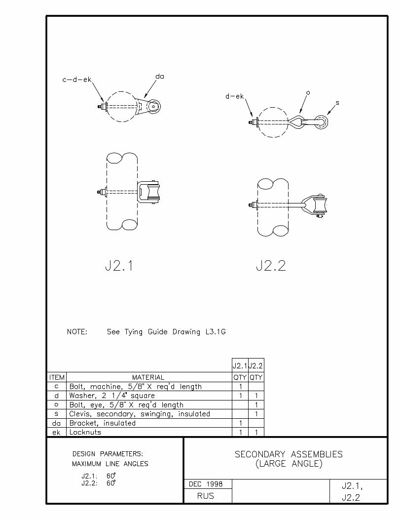
J2.1, J2.2 SECONDARY ASSEMBLIES (LARGE ANGLE)
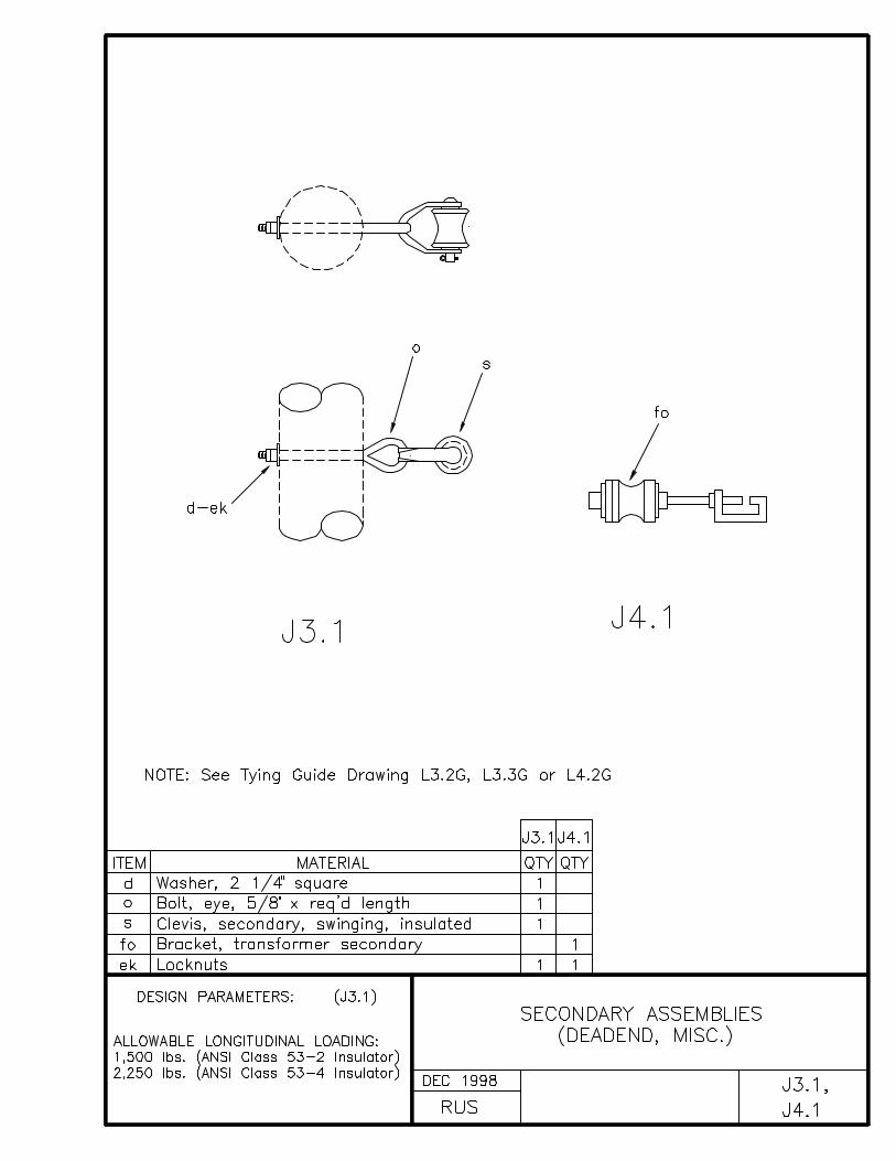
J3.1, J4.1 SECONDARY ASSEMBLIES (DEADEND, MISC.)
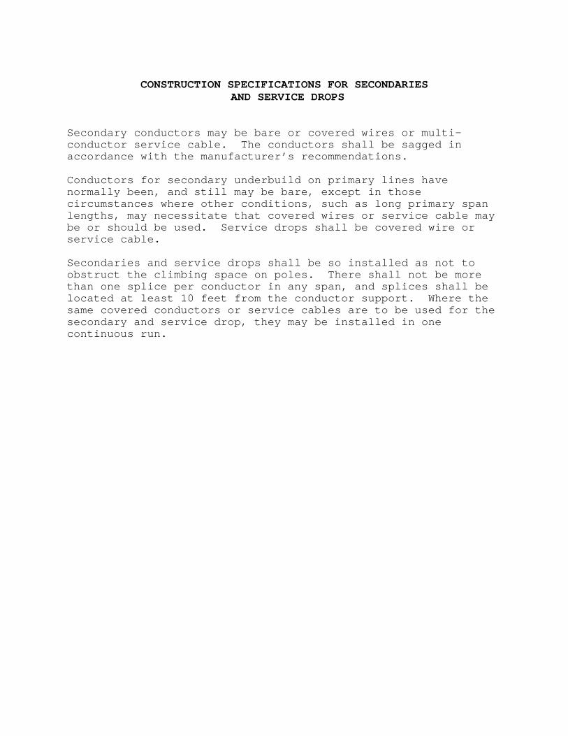
CONSTRUCTION SPECIFICATIONS FOR SECONDARIES AND SERVICE DROPS
Secondary conductors may be bare or covered wires or multi-conductor service cable. The conductors shall be sagged inaccordance with the manufacturer’s recommendations.
Conductors for secondary underbuild on primary lines havenormally been, and still may be bare, except in thosecircumstances where other conditions, such as long primary spanlengths, may necessitate that covered wires or service cable maybe or should be used. Service drops shall be covered wire orservice cable.
Secondaries and service drops shall be so installed as not toobstruct the climbing space on poles. There shall not be morethan one splice per conductor in any span, and splices shall belocated at least 10 feet from the conductor support. Where thesame covered conductors or service cables are to be used for thesecondary and service drop, they may be installed in onecontinuous run.
INDEX K
SERVICE ASSEMBLY UNITS
DRAWING NUMBER DRAWING TITLE (DESCRIPTION)
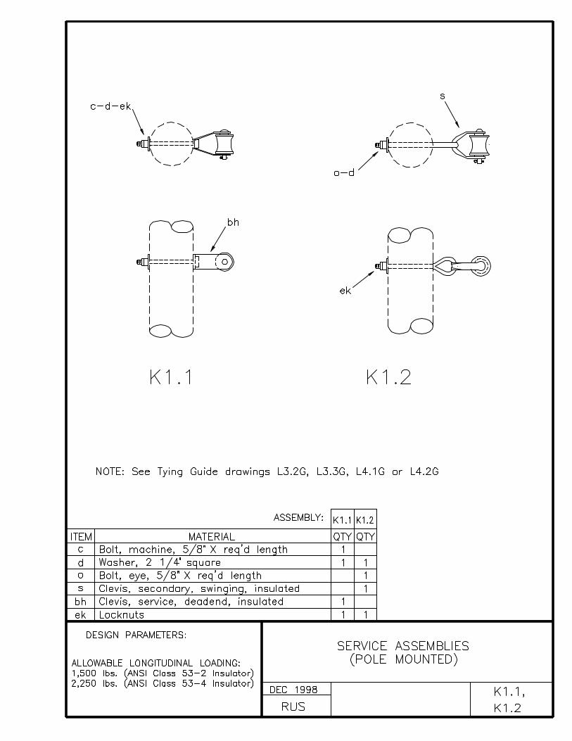
K1.1, K1.2 SERVICE ASSEMBLIES (POLE MOUNTED)
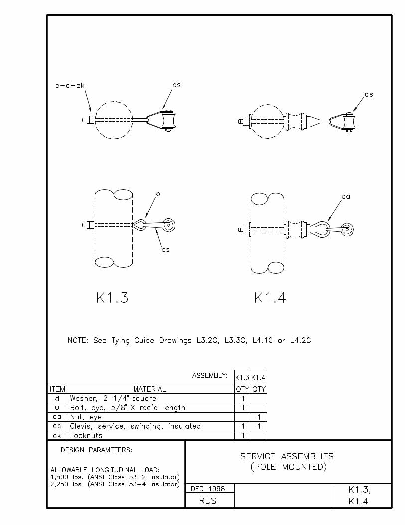
K1.3, K1.4 SERVICE ASSEMBLIES (POLE MOUNTED)
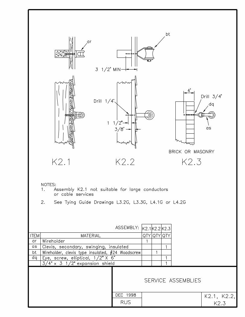
K2.1, K2.2, K2.3 SERVICE ASSEMBLIES
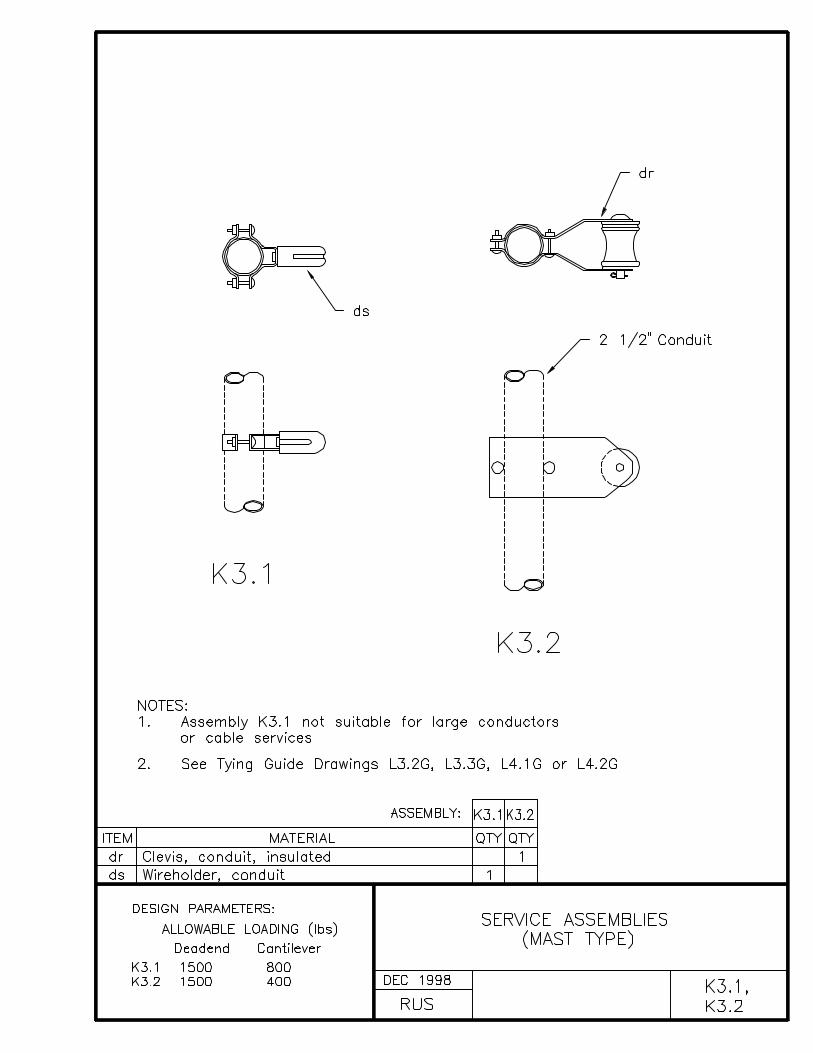
K3.1, K3.2 SERVICE ASSEMBLIES (MAST TYPE)
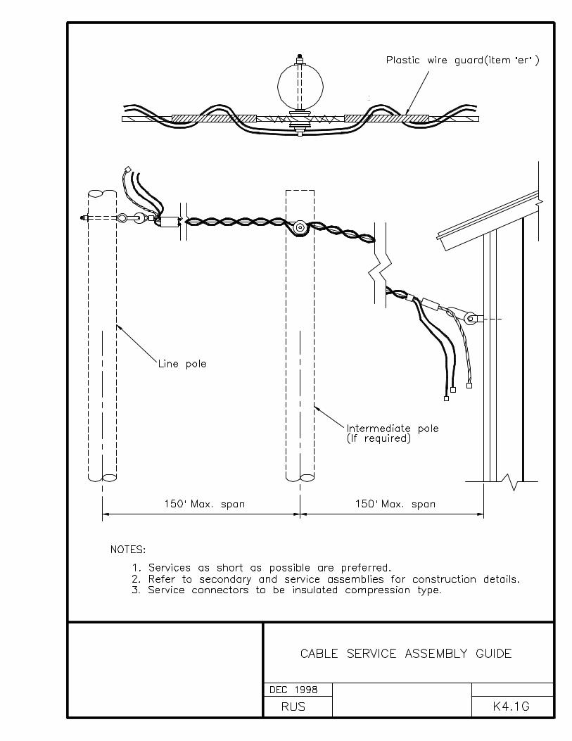
K4.1G CABLE SERVICE ASSEMBLY GUIDE
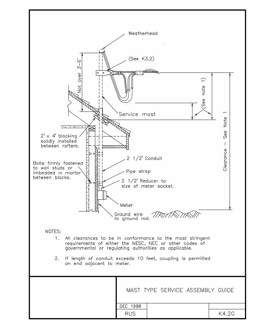
K4.2G MAST TYPE SERVICE ASSEMBLY GUIDE
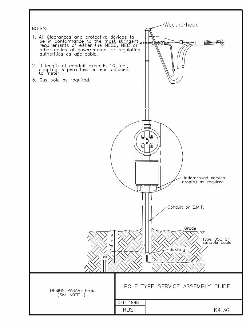
K4.3G POLE TYPE SERVICE ASSEMBLY GUIDE
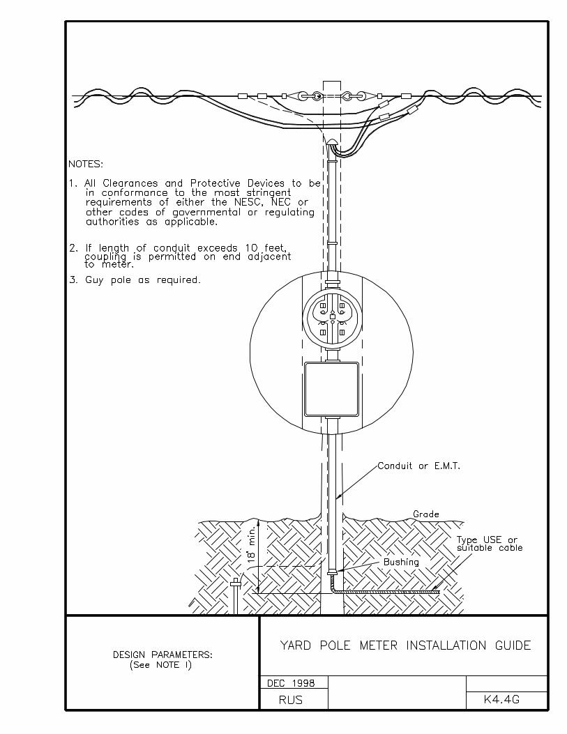
K4.4G YARD POLE METER INSTALLATION GUIDE
INDEX L
TYING GUIDES
DRAWING NUMBER DRAWING TITLE (DESCRIPTION)
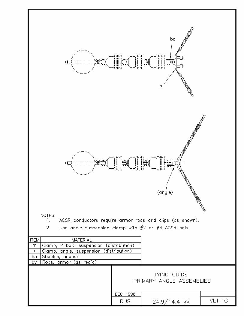
VL1.1G TYING GUIDEPRIMARY ANGLE ASSEMBLIES
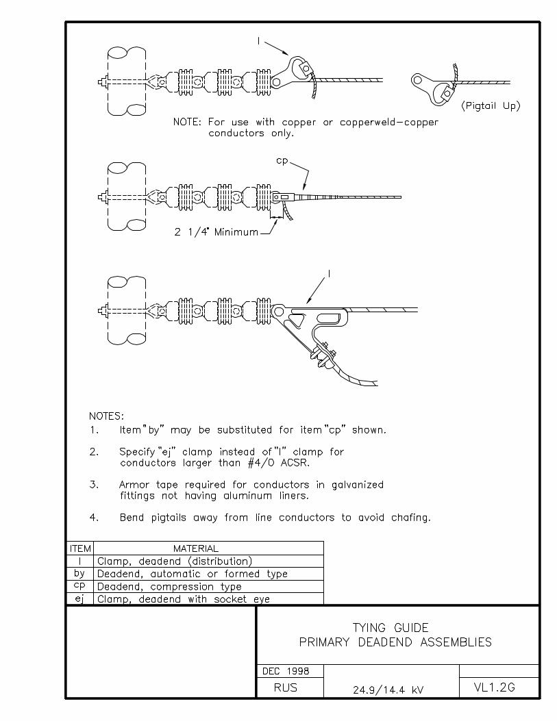
VL1.2G TYING GUIDEPRIMARY DEADEND ASSEMBLIES
L2.1G TYING GUIDENEUTRAL ANGLE ASSEMBLIES
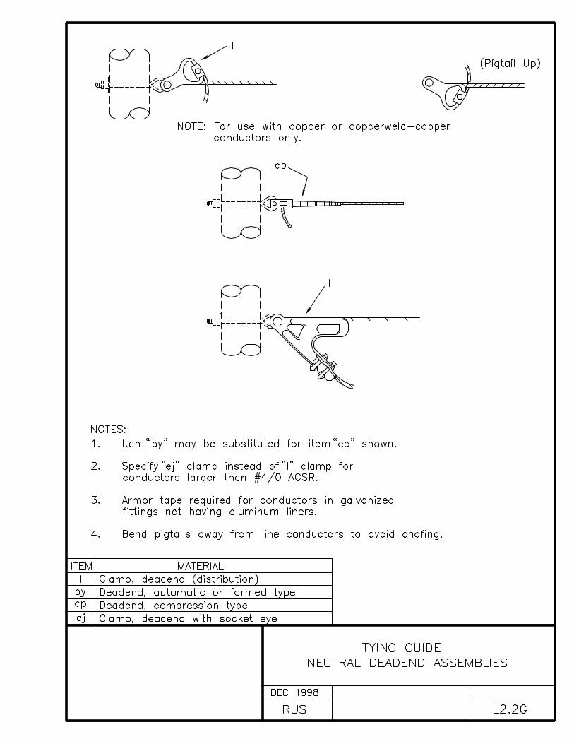
L2.2G TYING GUIDENEUTRAL DEADEND ASSEMBLIES
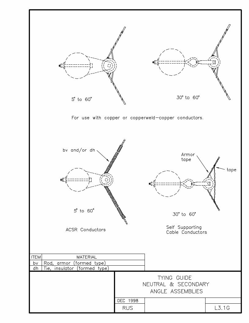
L3.1G TYING GUIDENEUTRAL & SECONDARY ANGLE ASSEMBLIES
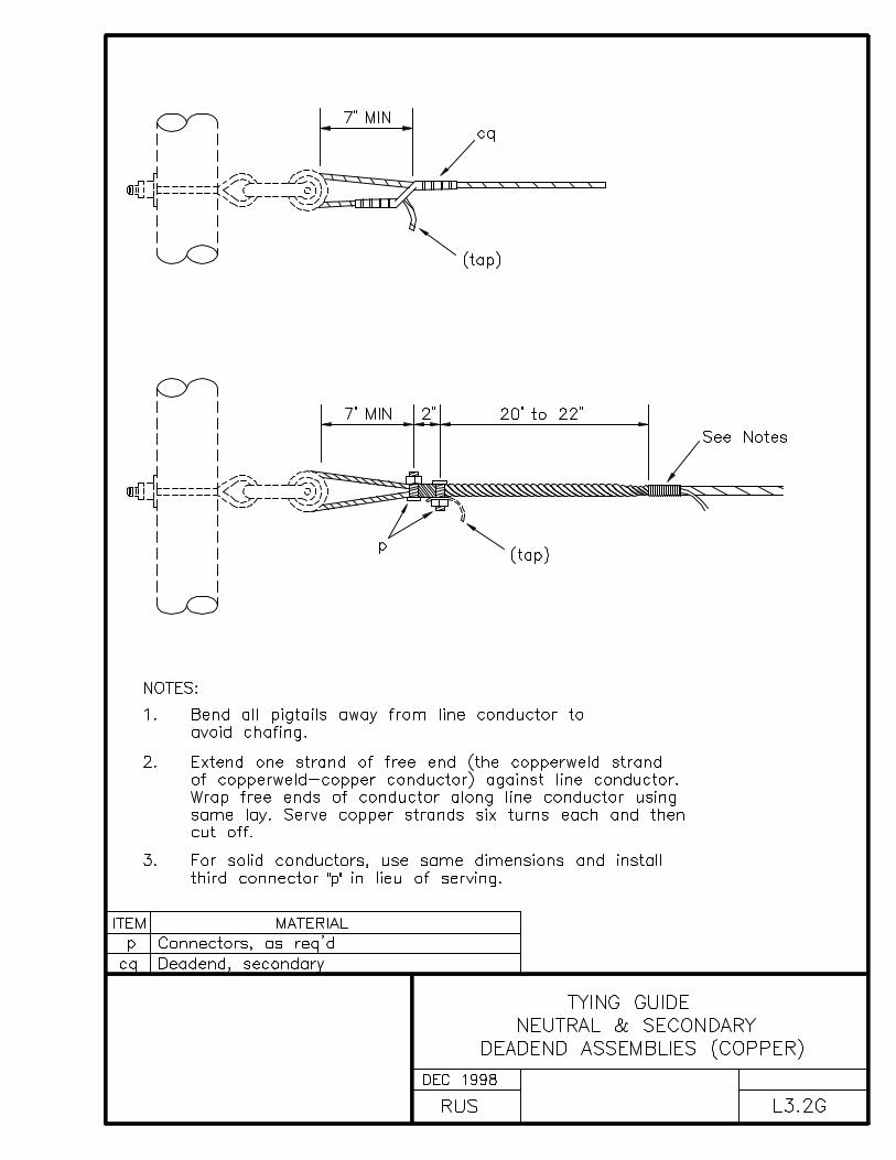
L3.2G TYING GUIDENEUTRAL & SECONDARY DEADEND ASSEMBLIES (COPPER)
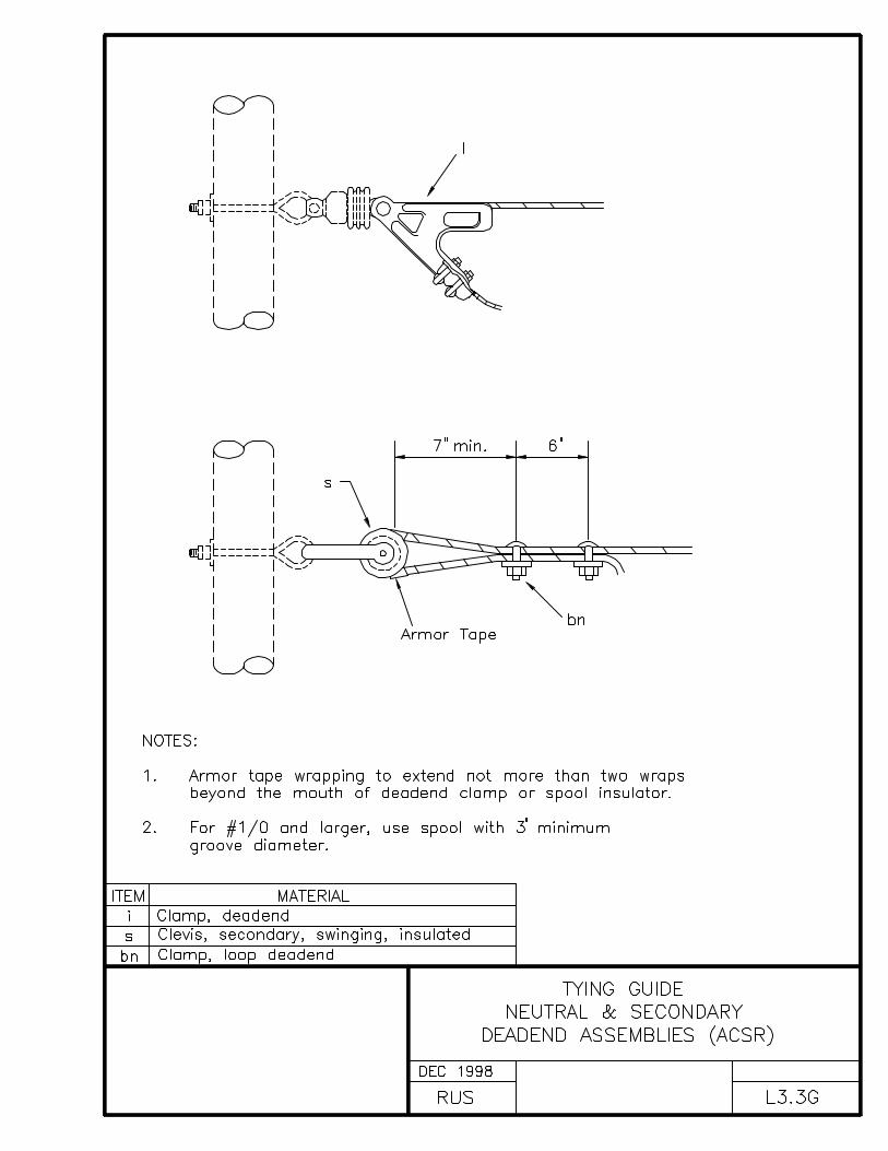
L3.3G TYING GUIDENEUTRAL & SECONDARY DEADEND ASSEMBLIES (ACSR)
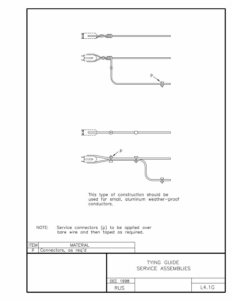
L4.1G TYING GUIDESERVICE ASSEMBLIES
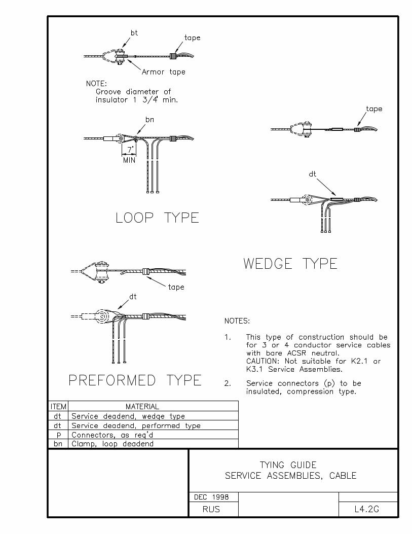
L4.2G TYING GUIDESERVICE ASSEMBLIES, CABLE

INDEX M
MISCELLANEOUS ASSEMBLY UNITS AND GUIDES
DRAWING NUMBER DRAWING TITLE (DESCRIPTION)
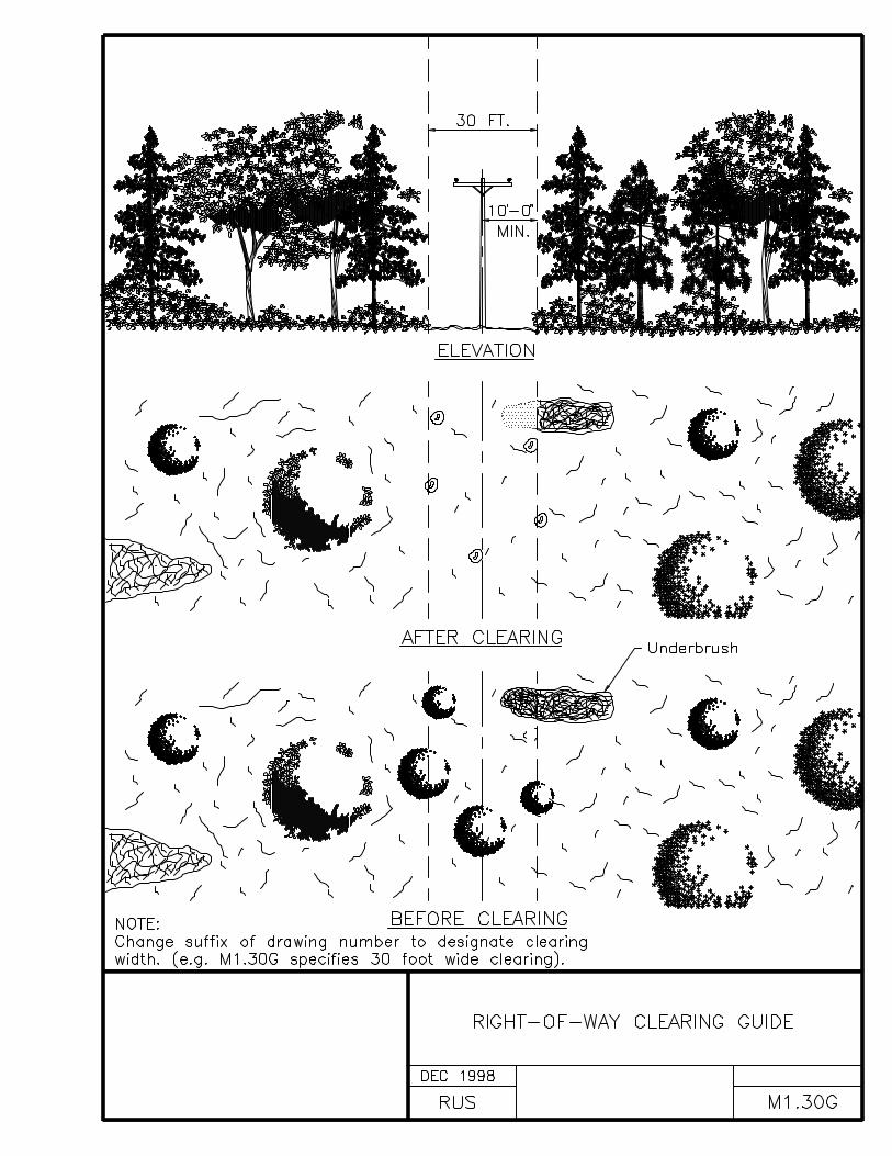
M1.30G RIGHT-OF-WAY CLEARING GUIDE
RIGHT-OF-WAY CLEARING SPECIFICATIONS
The right-of-way shall be prepared by removing trees, clearingunderbrush, and trimming trees so that the right-of-way iscleared close to the ground and to the width specified. However,low growing shrubs, which will not interfere with the operationor maintenance of the line, shall be left undisturbed if sodirected by the owner. Slash may be chipped and blown on theright-of-way if so specified.
The landowner’s written permission shall be received prior tocutting trees outside of the right-of-way. Trees fronting eachside of the right-of-way shall be trimmed symmetrically unlessotherwise specified. Dead trees beyond the right-of-way whichwould strike the line in falling shall be removed. Leaning treesbeyond the right-of-way which would strike the line in fallingand which would require topping if not removed, shall either beremoved or topped, except that shade, fruit, or ornamental treesshall be trimmed and not removed, unless otherwise authorized.

INDEX N
NEUTRAL ASSEMBLY UNITS
DRAWING NUMBER DRAWING TITLE (DESCRIPTION)
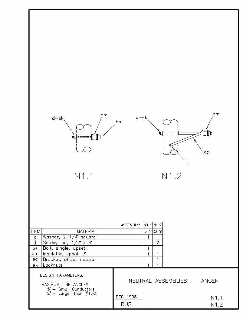
N1.1, N1.2 NEUTRAL ASSEMBLIES - TANGENT
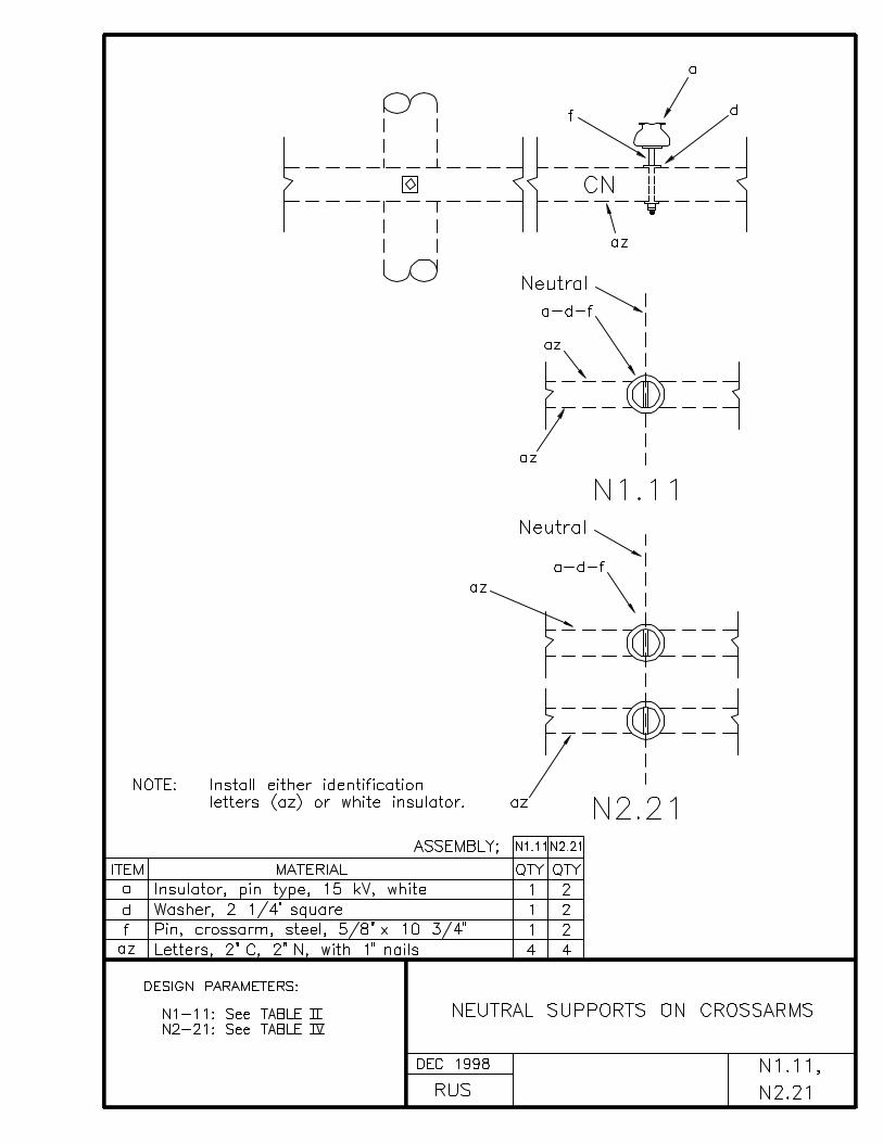
N1.11, N2.21 NEUTRAL SUPPORTS ON CROSSARMS
N2.1, N2.1L, N3.1 NEUTRAL ASSEMBLIES - LARGE ANGLE
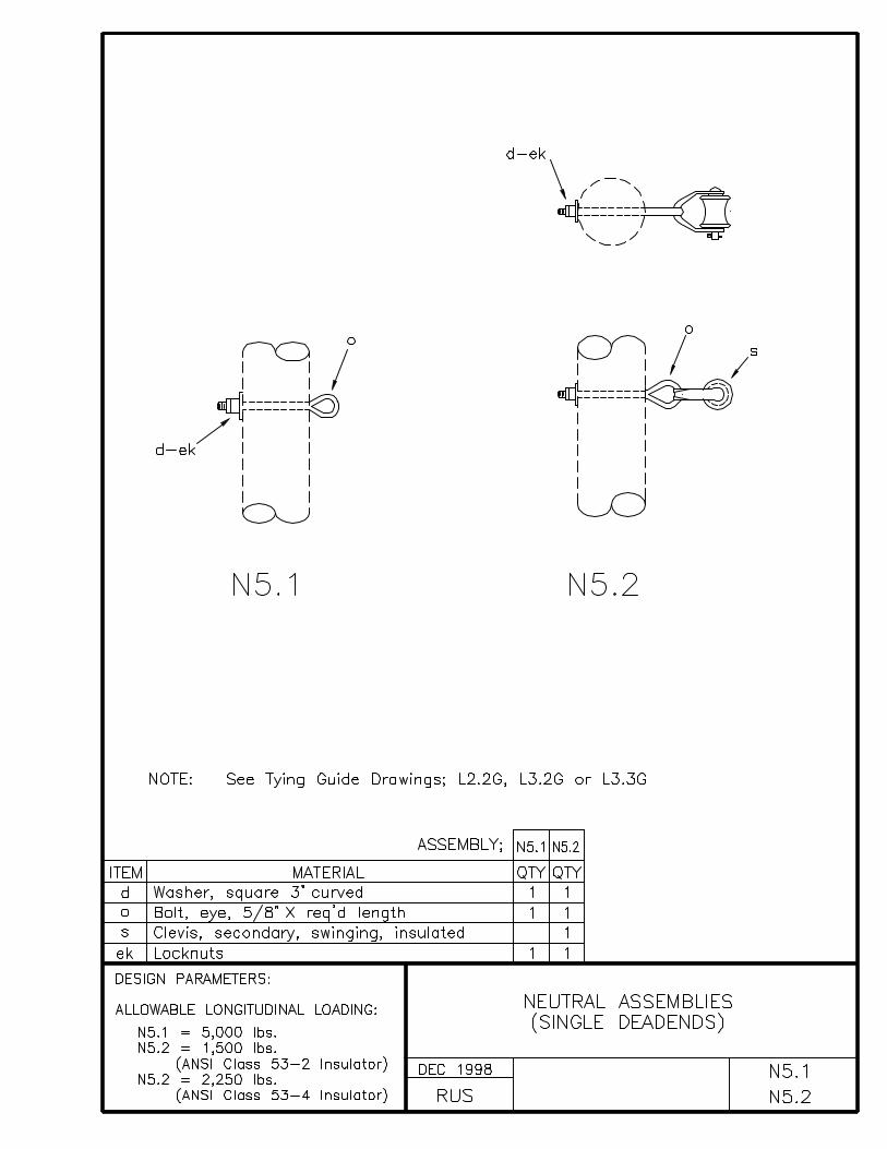
N5.1, N5.2 NEUTRAL ASSEMBLIES - SINGLE DEADENDS
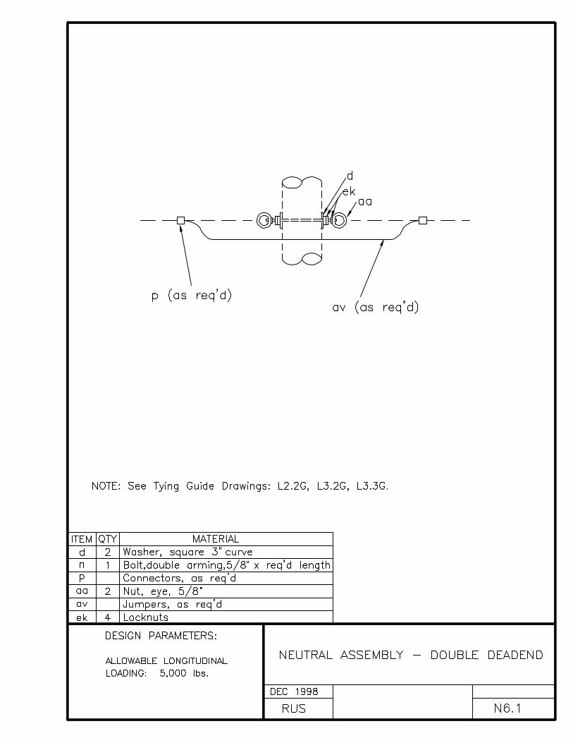
N6.1 NEUTRAL ASSEMBLY - DOUBLE DEADEND
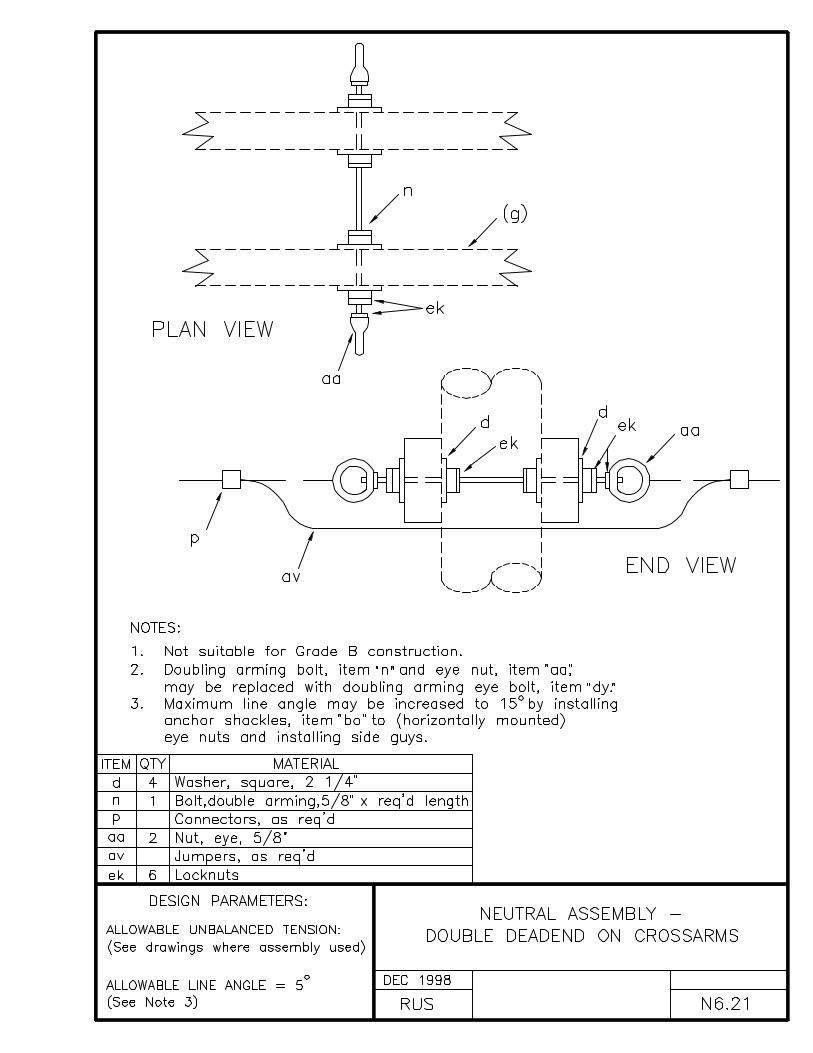
N6.21 NEUTRAL ASSEMBLY - DOUBLE DEADEND ON CROSSARMS
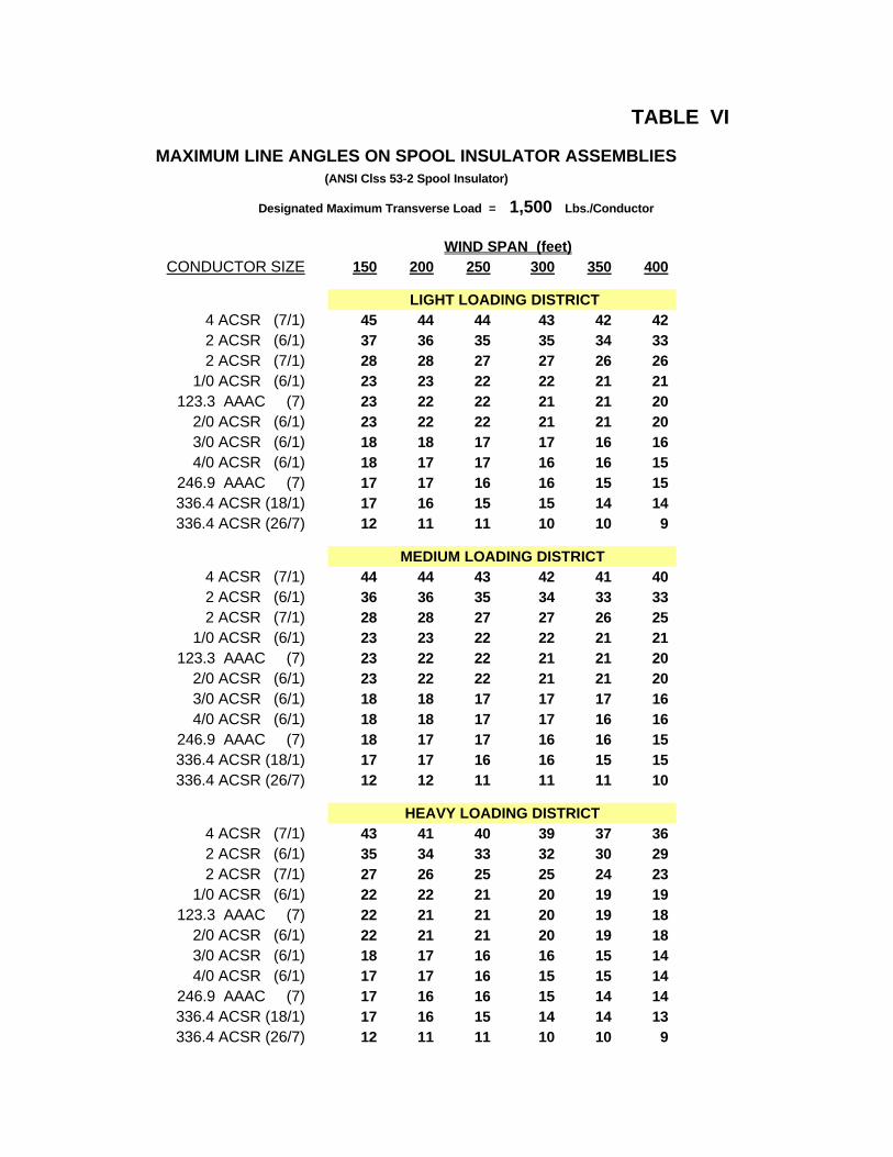
TABLE VI
MAXIMUM LINE ANGLES ON SPOOL INSULATOR ASSEMBLIES(ANSI Clss 53-2 Spool Insulator)
Designated Maximum Transverse Load = 1,500 Lbs./Conductor
WIND SPAN (feet)CONDUCTOR SIZE 150 200 250 300 350 400
LIGHT LOADING DISTRICT4 ACSR (7/1) 45 44 44 43 42 422 ACSR (6/1) 37 36 35 35 34 332 ACSR (7/1) 28 28 27 27 26 26
1/0 ACSR (6/1) 23 23 22 22 21 21123.3 AAAC (7) 23 22 22 21 21 20
2/0 ACSR (6/1) 23 22 22 21 21 203/0 ACSR (6/1) 18 18 17 17 16 164/0 ACSR (6/1) 18 17 17 16 16 15
246.9 AAAC (7) 17 17 16 16 15 15336.4 ACSR (18/1) 17 16 15 15 14 14336.4 ACSR (26/7) 12 11 11 10 10 9
MEDIUM LOADING DISTRICT4 ACSR (7/1) 44 44 43 42 41 402 ACSR (6/1) 36 36 35 34 33 332 ACSR (7/1) 28 28 27 27 26 25
1/0 ACSR (6/1) 23 23 22 22 21 21123.3 AAAC (7) 23 22 22 21 21 20
2/0 ACSR (6/1) 23 22 22 21 21 203/0 ACSR (6/1) 18 18 17 17 17 164/0 ACSR (6/1) 18 18 17 17 16 16
246.9 AAAC (7) 18 17 17 16 16 15336.4 ACSR (18/1) 17 17 16 16 15 15336.4 ACSR (26/7) 12 12 11 11 11 10
HEAVY LOADING DISTRICT4 ACSR (7/1) 43 41 40 39 37 362 ACSR (6/1) 35 34 33 32 30 292 ACSR (7/1) 27 26 25 25 24 23
1/0 ACSR (6/1) 22 22 21 20 19 19123.3 AAAC (7) 22 21 21 20 19 18
2/0 ACSR (6/1) 22 21 21 20 19 183/0 ACSR (6/1) 18 17 16 16 15 144/0 ACSR (6/1) 17 17 16 15 15 14
246.9 AAAC (7) 17 16 16 15 14 14336.4 ACSR (18/1) 17 16 15 14 14 13336.4 ACSR (26/7) 12 11 11 10 10 9

TABLE VII
MAXIMUM LINE ANGLES ON SPOOL INSULATOR ASSEMBLIES(ANSI Clss 53-4 Spool Insulator)
Designated Maximum Transverse Load = 1,500 Lbs./Conductor
WIND SPAN (feet)CONDUCTOR SIZE 150 200 250 300 350 400
LIGHT LOADING DISTRICT4 ACSR (7/1) 45 44 44 43 42 422 ACSR (6/1) 37 36 35 35 34 332 ACSR (7/1) 28 28 27 27 26 26
1/0 ACSR (6/1) 23 23 22 22 21 21123.3 AAAC (7) 23 22 22 21 21 20
2/0 ACSR (6/1) 23 22 22 21 21 203/0 ACSR (6/1) 18 18 17 17 16 164/0 ACSR (6/1) 18 17 17 16 16 15
246.9 AAAC (7) 17 17 16 16 15 15336.4 ACSR (18/1) 17 16 15 15 14 14336.4 ACSR (26/7) 12 11 11 10 10 9
MEDIUM LOADING DISTRICT4 ACSR (7/1) 44 44 43 42 41 402 ACSR (6/1) 36 36 35 34 33 332 ACSR (7/1) 28 28 27 27 26 25
1/0 ACSR (6/1) 23 23 22 22 21 21123.3 AAAC (7) 23 22 22 21 21 20
2/0 ACSR (6/1) 23 22 22 21 21 203/0 ACSR (6/1) 18 18 17 17 17 164/0 ACSR (6/1) 18 18 17 17 16 16
246.9 AAAC (7) 18 17 17 16 16 15336.4 ACSR (18/1) 17 17 16 16 15 15336.4 ACSR (26/7) 12 12 11 11 11 10
HEAVY LOADING DISTRICT4 ACSR (7/1) 43 41 40 39 37 362 ACSR (6/1) 35 34 33 32 30 292 ACSR (7/1) 27 26 25 25 24 23
1/0 ACSR (6/1) 22 22 21 20 19 19123.3 AAAC (7) 22 21 21 20 19 18
2/0 ACSR (6/1) 22 21 21 20 19 183/0 ACSR (6/1) 18 17 16 16 15 144/0 ACSR (6/1) 17 17 16 15 15 14
246.9 AAAC (7) 17 16 16 15 14 14336.4 ACSR (18/1) 17 16 15 14 14 13336.4 ACSR (26/7) 12 11 11 10 10 9

INDEX P
PROTECTION ASSEMBLY UNITS
DRAWING NUMBER DRAWING TITLE (DESCRIPTION)
VP1.01, VP1.1 SURGE ARRESTER - SINGLE PHASE
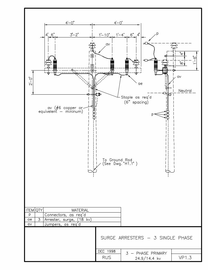
VP1.3 SURGE ARRESTER - 3 SINGLE PHASE
P2.1 POLE PROTECTION ASSEMBLY - PLATE TYPE
P2.2, P2.3 POLE PROTECTION ASSEMBLY - WRAP-AROUND TYPE
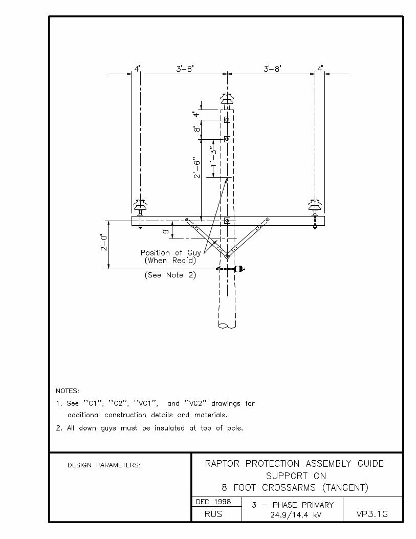
VP3.1G RAPTOR PROTECTION ASSEMBLY GUIDESUPPORT ON 8 FOOT CROSSARMS (TANGENT)
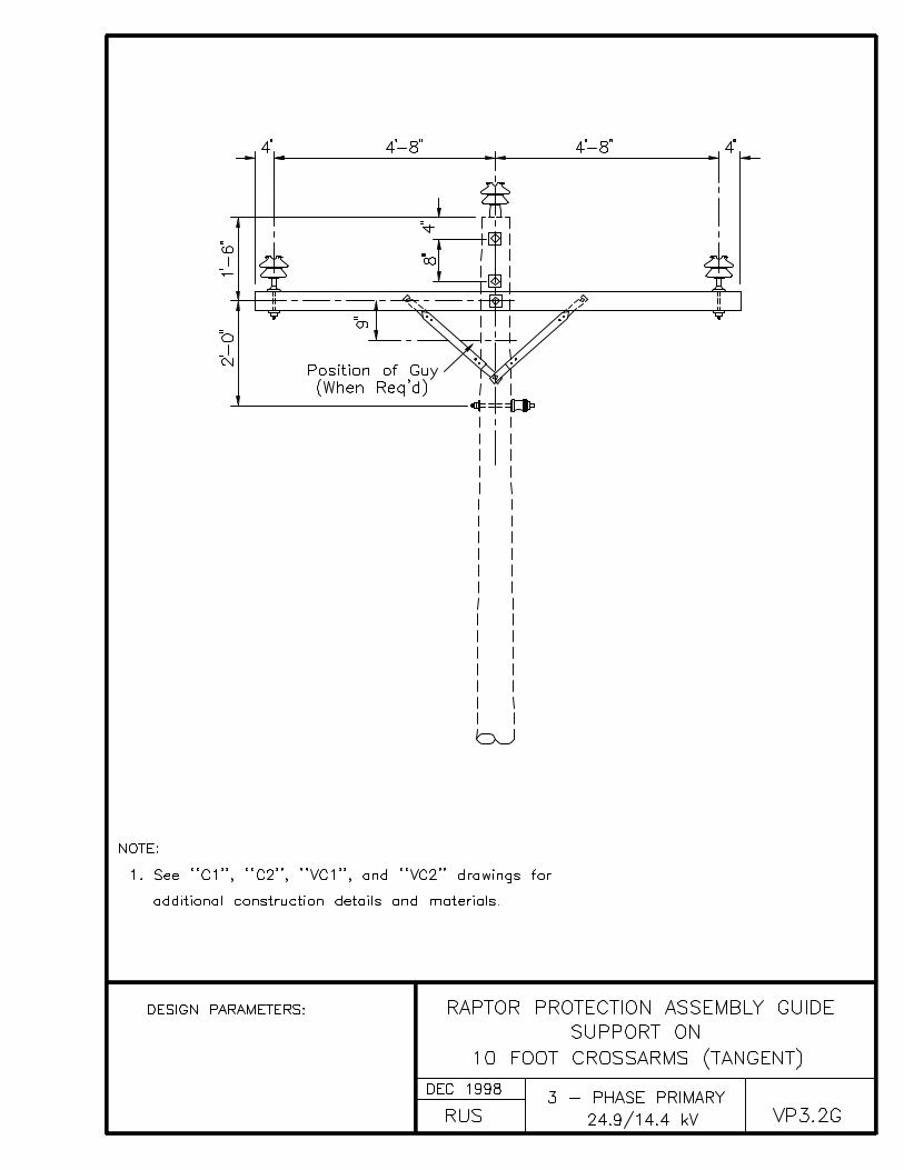
VP3.2G RAPTOR PROTECTION ASSEMBLY GUIDESUPPORT ON 10 FOOT CROSSARMS (TANGENT)
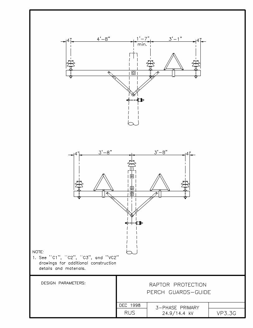
VP3.3G RAPTOR PROTECTION PERCH GUARDS - GUIDE

INDEX Q
METERING ASSEMBLY UNITS
DRAWING NUMBER DRAWING TITLE (DESCRIPTION)
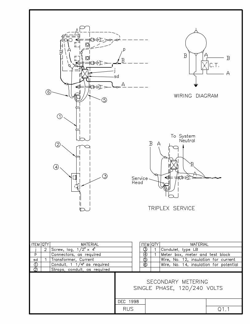
Q1.1 SECONDARY METERINGSINGLE PHASE, 120/240 VOLTS
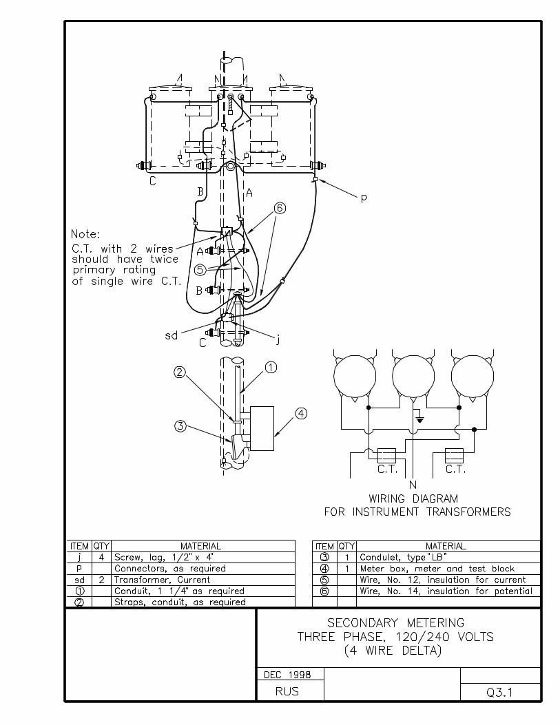
Q3.1 SECONDARY METERINGTHREE PHASE, 120/240 VOLTS(4 WIRE DELTA)
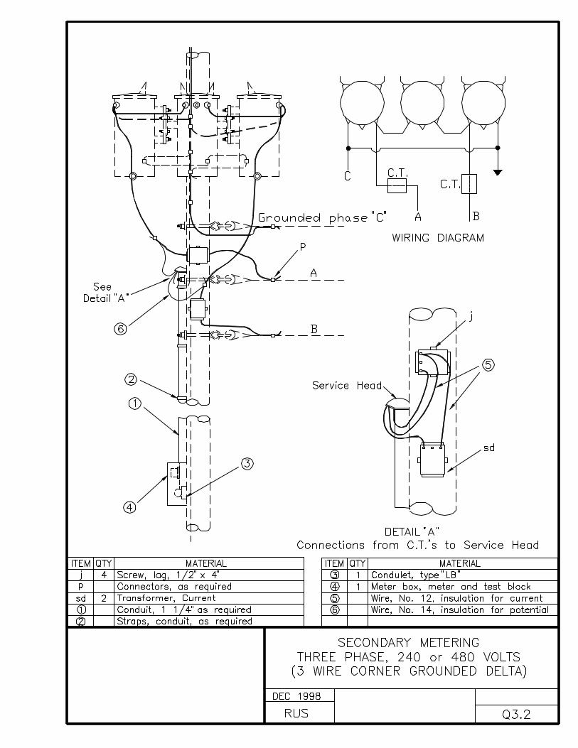
Q3.2 SECONDARY METERINGTHREE PHASE, 240 or 480 VOLTS(3 WIRE CORNER GROUNDED DELTA)
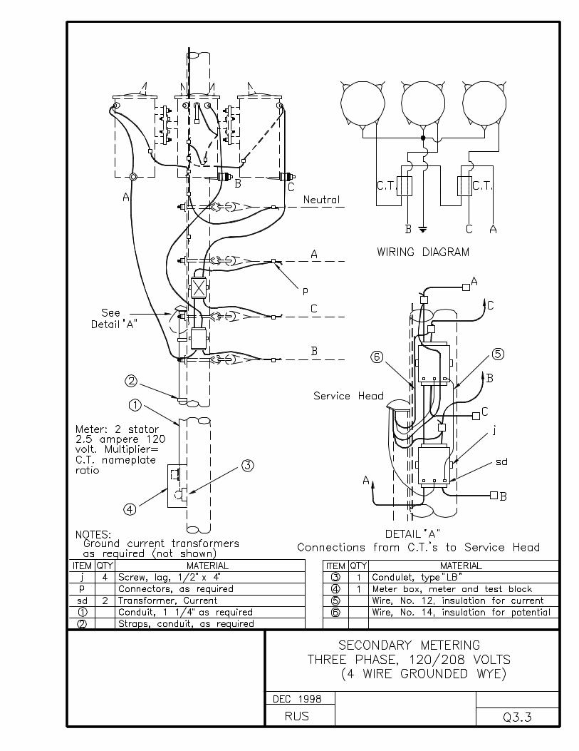
Q3.3 SECONDARY METERINGTHREE PHASE, 120/208 VOLTS(4 WIRE GROUNDED WYE)
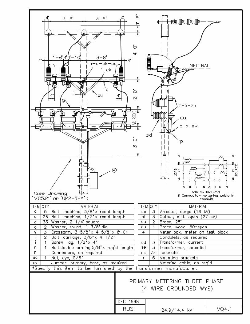
VQ4.1 PRIMARY METERING, THREE PHASE(4 WIRE GROUNDED WYE)
INDEX R
OIL CIRCUIT RECLOSER ASSEMBLY UNITS
DRAWING NUMBER DRAWING TITLE (DESCRIPTION)
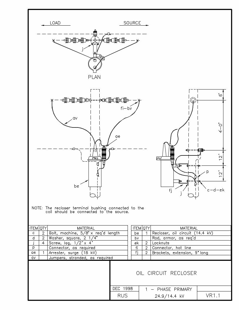
VR1.1 OIL CIRCUIT RECLOSER
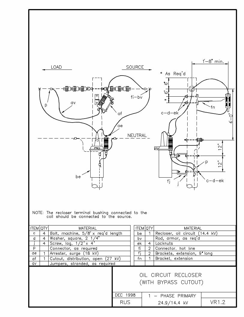
VR1.2 OIL CIRCUIT RECLOSER (WITH BYPASS CUTOUT)
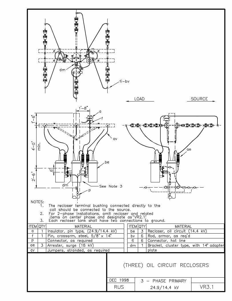
VR3.1 (THREE) OIL CIRCUIT RECLOSERS
VR3.2 (THREE) OIL CIRCUIT RECLOSERS (WITH BYPASS SWITCHES)
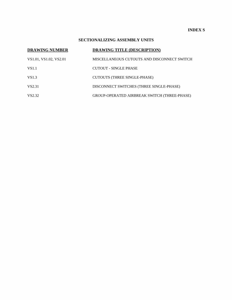
INDEX S
SECTIONALIZING ASSEMBLY UNITS
DRAWING NUMBER DRAWING TITLE (DESCRIPTION)
VS1.01, VS1.02, VS2.01 MISCELLANEOUS CUTOUTS AND DISCONNECT SWITCH
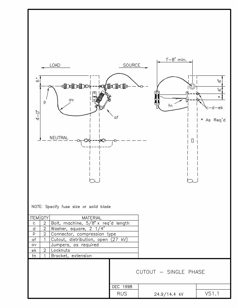
VS1.1 CUTOUT - SINGLE PHASE
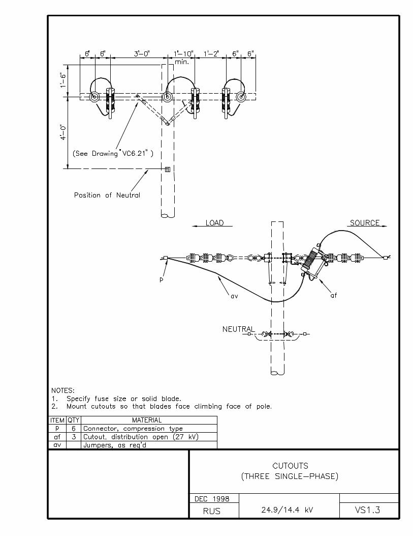
VS1.3 CUTOUTS (THREE SINGLE-PHASE)
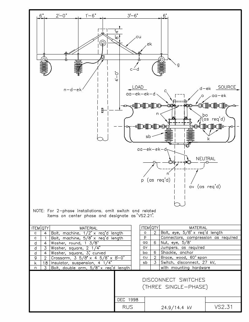
VS2.31 DISCONNECT SWITCHES (THREE SINGLE-PHASE)
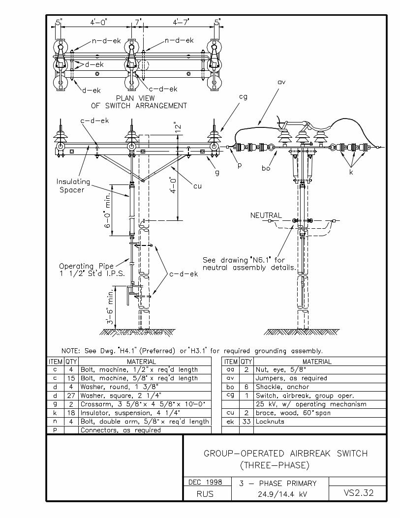
VS2.32 GROUP-OPERATED AIRBREAK SWITCH (THREE-PHASE)

INDEX W
WOOD POLES, CROSSARMS AND BRACES
DRAWING NUMBER DRAWING TITLE (DESCRIPTION)
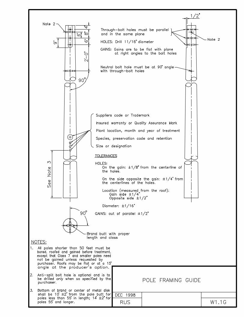
W1.1G POLE FRAMING GUIDE
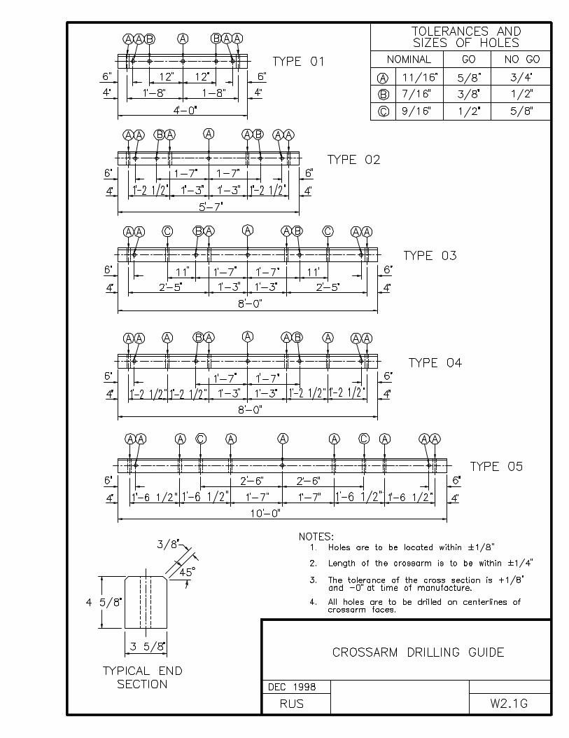
W2.1G CROSSARM DRILLING GUIDE
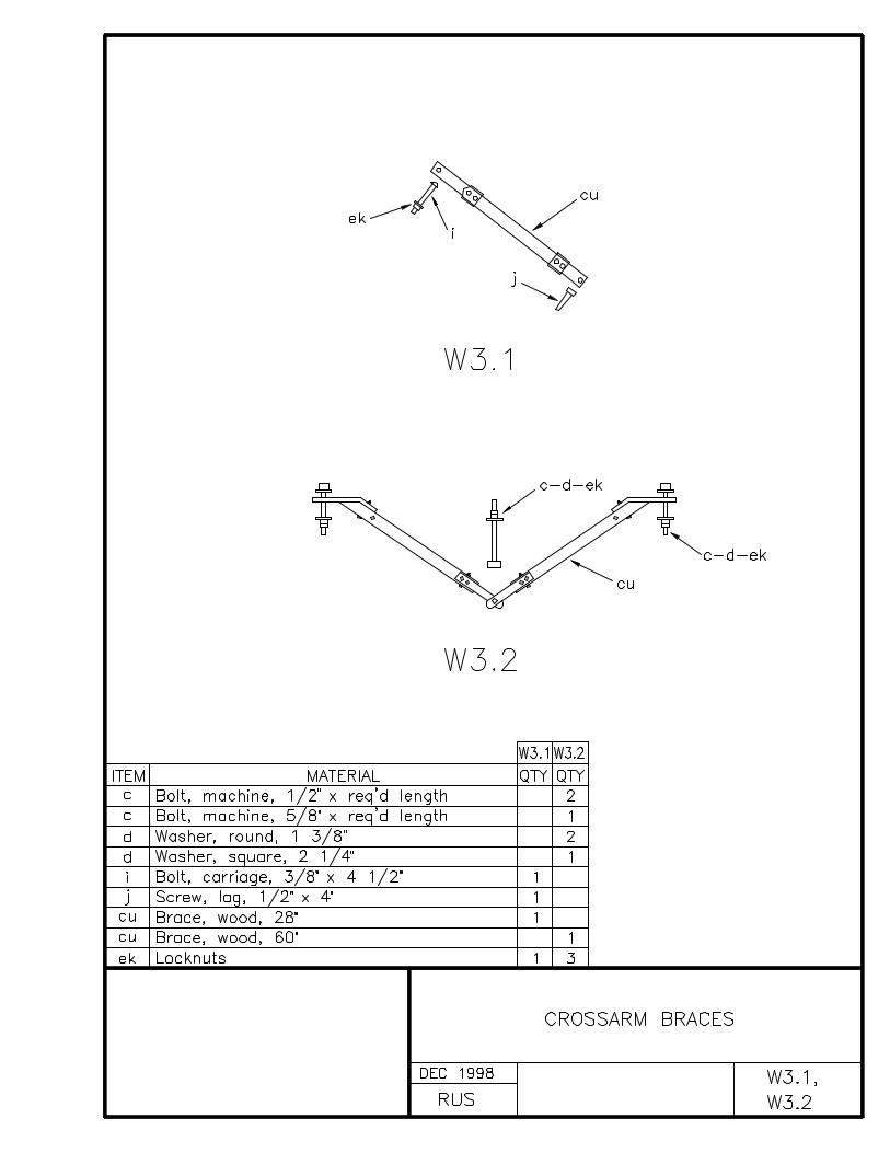
W3.1, W3.2 CROSSARM BRACES
CONSTRUCTION SPECIFICATIONS FOR POLES AND CROSSARMS
In distributing the poles, large, choice, dense poles shall beused at transformer, deadend, angle, and corner locations.
Poles shall be set so that alternate crossarm gains face inopposite directions, except at terminal and deadends where thegains of the last two (2) poles shall be on the side facing theterminal or deadend. On unusually long spans, the poles shall beset so that the crossarm is located on the side of the pole awayfrom the long span. On lines that curve, crossarms shall beinstalled on the side of the pole which faces the midpoint of thecurve. On sloping terrain, crossarms shall be installed on theuphill side of the pole. Where pole top insulator brackets orpole top pins are used, they shall be located on the oppositeside of the pole from the gain.
Poles shall be set in an alignment and plumb, except at corners,terminal, angles, junctions, or other points of strain, wherethey shall be set and raked against the strain so that theconductors are in line.
Poles shall be raked against the conductor strain not less than 1inch for each 10 feet of pole length nor more than 2 inches foreach 10 feet of pole length after the conductors are installed atthe required tension.
Pole backfill shall be thoroughly tamped in full depth. Excessdirt shall be banked around the pole.

TABLE W
Pole Setting Depths
The minimum depth for setting poles must be as follows:
Length of Pole (Feet)
Setting in Soil (Feet)
Setting in All Solid Rock (Feet)
20 4.0 3.025 5.0 3.530 5.5 3.535 6.0 4.040 6.0 4.045 6.5 4.550 7.0 4.555 7.5 5.060 8.0 5.0
“Setting in Soil” depths must apply:
A. Where poles are to be set in soil; B. Where there is a layer of soil or more than two (2) feet in depth over solid rock; C. Where the hole in solid rock is not substantially vertical or the diameter of the hole at the
surface of the rock exceeds approximately twice the diameter of the pole at the same level.
“Setting in All Solid Rock” depths must apply where poles are tobe set in solid rock and where the hole is substantiallyvertical, approximately uniform in diameter and large enough topermit the use of tamping bars the full depth of the hole.
Where there is a layer of soil two (2) feet or less in depth oversolid rock, the depth of the hole must be the depth of the soilin addition to the depth specified under “Setting in All SolidRock” provided, however, that such depth must not exceed thedepth specified under “Setting in Soil.”
On sloping ground, the depth of the hole must be measured fromthe low side of the hole.
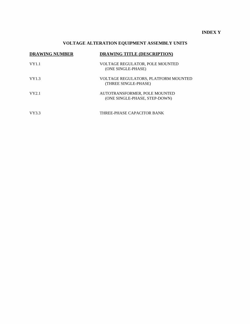
INDEX Y
VOLTAGE ALTERATION EQUIPMENT ASSEMBLY UNITS
DRAWING NUMBER DRAWING TITLE (DESCRIPTION)
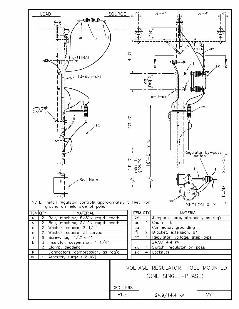
VY1.1 VOLTAGE REGULATOR, POLE MOUNTED (ONE SINGLE-PHASE)
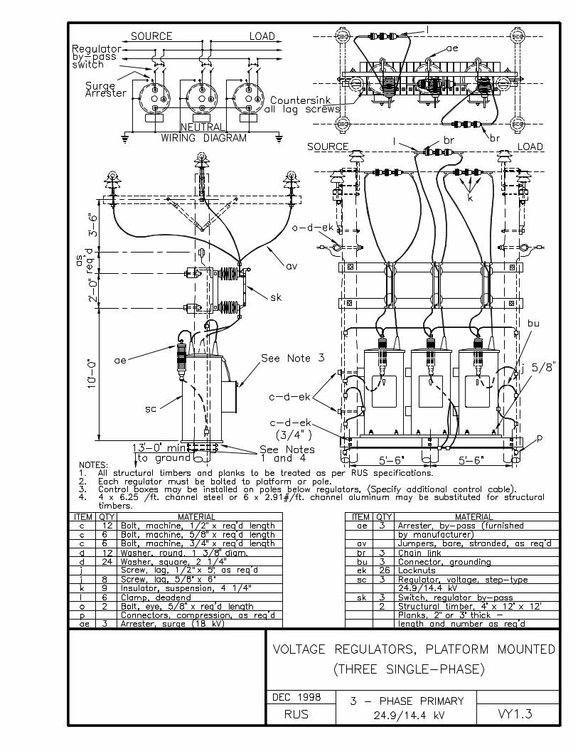
VY1.3 VOLTAGE REGULATORS, PLATFORM MOUNTED (THREE SINGLE-PHASE)
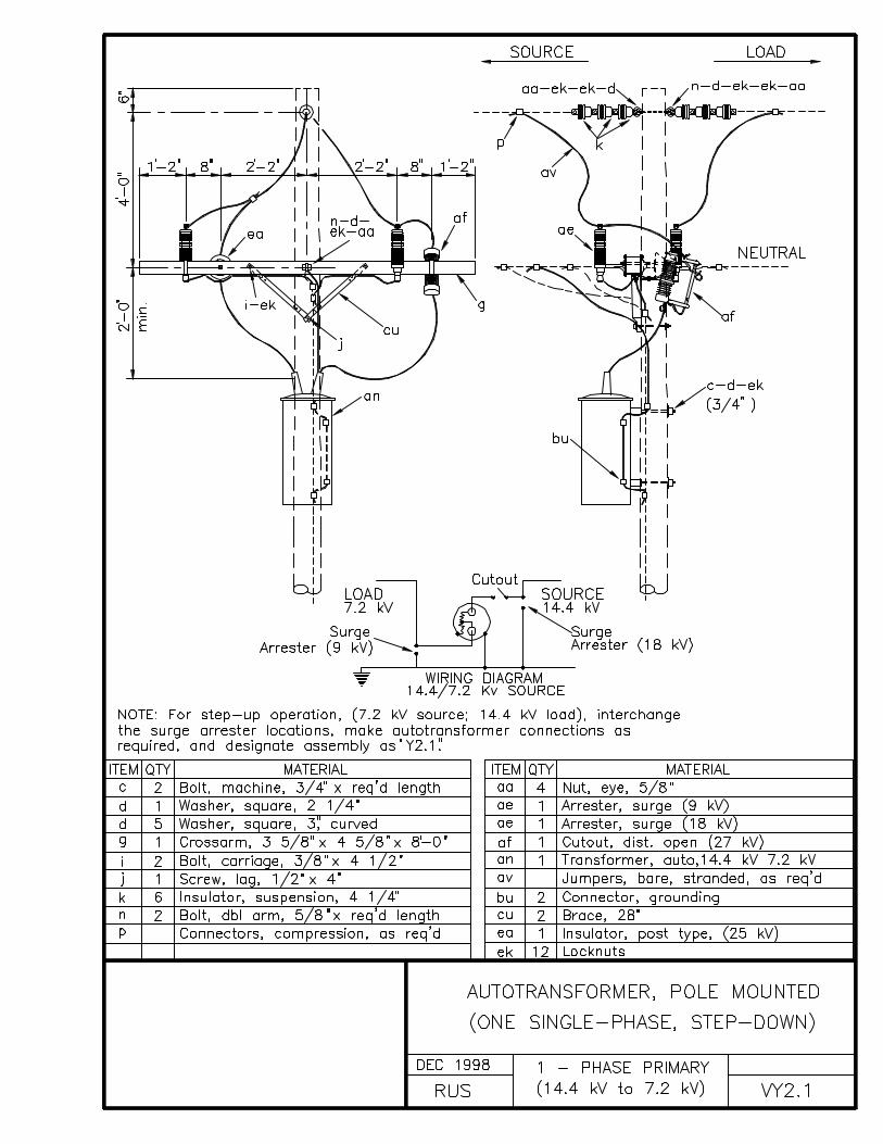
VY2.1 AUTOTRANSFORMER, POLE MOUNTED (ONE SINGLE-PHASE, STEP-DOWN)
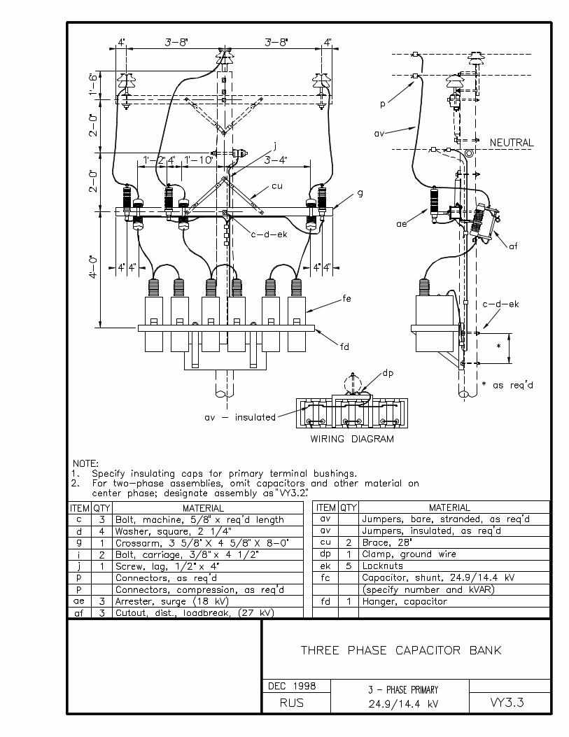
VY3.3 THREE-PHASE CAPACITOR BANK
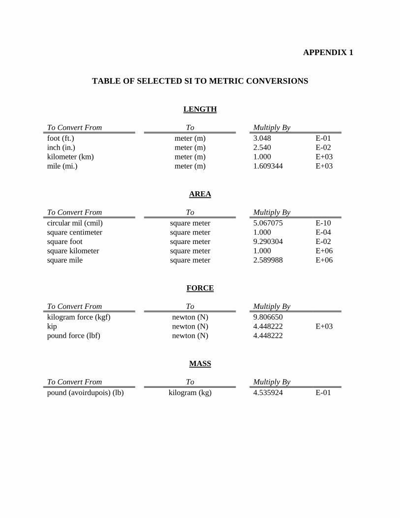
APPENDIX 1
TABLE OF SELECTED SI TO METRIC CONVERSIONS
LENGTH
To Convert From To Multiply Byfoot (ft.) meter (m) 3.048 E-01inch (in.) meter (m) 2.540 E-02kilometer (km) meter (m) 1.000 E+03mile (mi.) meter (m) 1.609344 E+03
AREA
To Convert From To Multiply Bycircular mil (cmil) square meter 5.067075 E-10square centimeter square meter 1.000 E-04square foot square meter 9.290304 E-02square kilometer square meter 1.000 E+06square mile square meter 2.589988 E+06
FORCE
To Convert From To Multiply Bykilogram force (kgf) newton (N) 9.806650kip newton (N) 4.448222 E+03pound force (lbf) newton (N) 4.448222
MASS
To Convert From To Multiply Bypound (avoirdupois) (lb) kilogram (kg) 4.535924 E-01
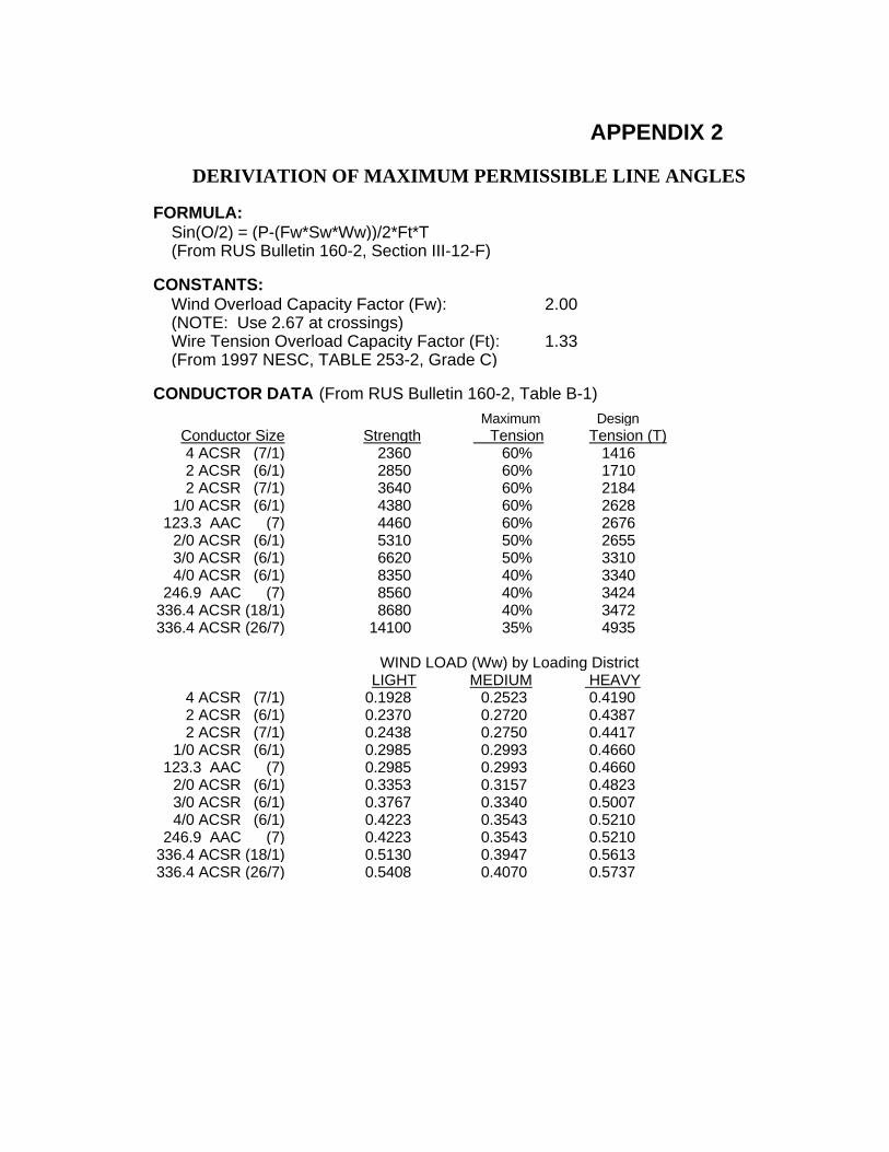
APPENDIX 2
DERIVIATION OF MAXIMUM PERMISSIBLE LINE ANGLES
FORMULA: Sin(O/2) = (P-(Fw*Sw*Ww))/2*Ft*T (From RUS Bulletin 160-2, Section III-12-F)
CONSTANTS: Wind Overload Capacity Factor (Fw): 2.00 (NOTE: Use 2.67 at crossings) Wire Tension Overload Capacity Factor (Ft): 1.33 (From 1997 NESC, TABLE 253-2, Grade C)
CONDUCTOR DATA:(From RUS Bulletin 160-2, Table B-1) Maximum Design
Conductor Size Strength Tension Tension (T)4 ACSR (7/1) 2360 60% 14162 ACSR (6/1) 2850 60% 17102 ACSR (7/1) 3640 60% 2184
1/0 ACSR (6/1) 4380 60% 2628123.3 AAC (7) 4460 60% 2676
2/0 ACSR (6/1) 5310 50% 26553/0 ACSR (6/1) 6620 50% 33104/0 ACSR (6/1) 8350 40% 3340
246.9 AAC (7) 8560 40% 3424336.4 ACSR (18/1) 8680 40% 3472336.4 ACSR (26/7) 14100 35% 4935
WIND LOAD (Ww) by Loading DistrictLIGHT MEDIUM HEAVY
4 ACSR (7/1) 0.1928 0.2523 0.41902 ACSR (6/1) 0.2370 0.2720 0.43872 ACSR (7/1) 0.2438 0.2750 0.4417
1/0 ACSR (6/1) 0.2985 0.2993 0.4660123.3 AAC (7) 0.2985 0.2993 0.4660
2/0 ACSR (6/1) 0.3353 0.3157 0.48233/0 ACSR (6/1) 0.3767 0.3340 0.50074/0 ACSR (6/1) 0.4223 0.3543 0.5210
246.9 AAC (7) 0.4223 0.3543 0.5210336.4 ACSR (18/1) 0.5130 0.3947 0.5613336.4 ACSR (26/7) 0.5408 0.4070 0.5737
Related Documents