IM05805014K For more information visit: www.chfire.com O & M Manual for the EATON LMR Plus Electric Fire Pump Controller Instructions

Welcome message from author
This document is posted to help you gain knowledge. Please leave a comment to let me know what you think about it! Share it to your friends and learn new things together.
Transcript

IM05805014K For more information visit: www.chfire.com
O & M Manual for the EATON LMR Plus ElectricFire Pump Controller
Instructions
Instruction Booklet LMR Plus Electric Fire Pump ControllerPage 2 Effective: October 2007
For more information visit: www.chfire.com IM05805014K
Description Page
1. INTRODUCTION ............................................................................................................ 32. INSTALLATION AND ELECTRICAL CONNECTIONS ................................................... 33. HARDWARE DESCRIPTION ......................................................................................... 54. OPERATION ................................................................................................................... 75. PROGRAMMING ............................................................................................................ 86. HISTORY, DIAGNOSTICS AND STATISTICS ............................................................. 137. COMMUNICATION ....................................................................................................... 148. CUSTOM MESSAGES ................................................................................................. 14APPENDIX A: MAIN MENU TREE .................................................................................. 16APPENDIX B: LANGUAGE MENU TREE ....................................................................... 17APPENDIX C: REGIONAL SETTINGS MENU TREE ..................................................... 18APPENDIX D: PRESSURE SETTINGS MENU TREE .................................................... 19APPENDIX E: TIMER VALUES MENU TREE ................................................................. 20APPENDIX F: ALARM SETPOINTS MENU TREE ........................................................... 21APPENDIX G: CUSTOMER INPUT/OUTPUT MENU TREE ........................................... 22APPENDIX G(A): CUSTOM INPUTS MENU TREE ........................................................ 23APPENDIX G(B): CUSTOM OUTPUTS MENU TREE .................................................... 24APPENDIX G(C): CUSTOM LIGHTS MENU TREE ........................................................ 25APPENDIX H: MAIN MENU PASSWORD MENU TREE ................................................ 26APPENDIX J: CUSTOM MESSAGE LOAD & ACTIVATION ........................................... 27APPENDIX K: POWER WIRE CABLE REFERENCE ...................................................... 28APPENDIX L: ALARM/STATUS MESSAGES .................................................................. 29
LMR Plus Electric Fire Pump Controller
Instruction BookletEffective: October 2007 Page 3
IM05805014K For more information visit: www.chfire.com
1. INTRODUCTION1.1 Safety
This technical document is intended to cover mostaspects associated with the installation, application,operation, and maintenance of the LMR Plus Fire PumpController. It is provided as a guide for authorized andqualified personnel only in the selection and applicationof the LMR Plus Controller. If further information isrequired by the purchaser regarding particularinstallation, application, or maintenance activity, pleasecontact an authorized EATON sales agent or theinstalling contractor.
1.2 Warranty
No warranties, expressed or implied, includingwarranties of fitness for a particular purpose ofmerchantability, or warranties arising from course ofdealing or usage of trade, are made regarding theinformation, recommendations and descriptionscontained herein. In no event will EATON be responsibleto the purchaser or user in contract, in tort (includingnegligence), strict liability or otherwise for any special,indirect, incidental or consequential damage or losswhatsoever, including but not limited to damage or lossof use of equipment, plant or power system, cost ofcapital, loss of power, additional expenses in the use ofexisting power facilities, or claims against the purchaserof user by its customers resulting from the use of theinformation and descriptions contained herein.
1.3 Safety Precautions
All safety codes, safety standards, and/or regulationsmust be strictly observed in the installation, operation,and maintenance of this device.
1.4 Product Overview
The LMR Plus Controller is a comprehensive, multi-function microprocessor based Fire Pump Controller.
Designed to meet the needs of markets worldwide, theLMR Plus controller is certified by the followingauthorities: Underwrites Laboratories (UL), UnderwritersLaboratories of Canada (ULC), Factory Mutual (FM),
Canadian Standards Association (CSA), New YorkDepartment of Buildings (NYSB), and CE.
Starting types of the LMR Plus Fire Pump Controllerinclude the following: FD30-Across the Line, FD40-PartWinding, FD50-Primary Resistor, FD60-Autotransformer,FD70-Wye-Delta (Star-Delta) Open Transition, FD80-Wye-Delta (Star-Delta) Closed Transition, FD90-SoftStart, and FDM30-Medium Voltage Across the Line. Allproducts, except the FDM30, can be offered as anAdditive (Foam) system and/or with an Automatic PowerTransfer Switch.
2. INSTALLATION AND ELECTRICAL CONNECTIONS
2.1 Mounting
Carefully unpack the controller and inspect thoroughly.
The controller should be located as close as is practicalto the motor it controls and shall be within sight of theelectric motor, preferably ten feet or less.
The LMR Plus controller is designed for either wall orfloor mounting. Note that the controller is not freestanding and must be mounted with feet or boltedsecurely to a wall. For dimensional and weight dataplease refer to the respective data sheets for the varioustypes of Fire Pump Controllers.
2.2 Pressure Switch Connections
The LMR Plus is equipped with a pressure transducer.The controller is provided with a 1/4" NPT female systempressure connection located on the bottom, external sideof the enclosure. The connection should be installed asper NFPA, pamphlet no. 20.
The actual pressure is displayed on the middle left handside of the LCD display. Precise start and stop pressureset points can be programmed in the controller. Refer toSection 5 for programming instructions.
The pressure transducer and internal plumbingcomponents are rated for a maximum of 600PSI.
CAUTION
COMPLETELY READ AND UNDERSTAND THEMATERIAL PRESENTED IN THIS DOCUMENTBEFORE ATTEMPTING INSTALLATION,OPERATION, OR APPLICATION OF THEEQUIPMENT. IN ADDITION, ONLY QUALIFIEDPERSONS SHOULD BE PERMITTED TO PERFORMANY WORK ASSOCIATED WITH THIS EQUIPMENT.ANY WIRING INSTRUCTIONS PRESENTED IN THISDOCUMENT MUST BE FOLLOWED PRECISELY.FAILURE TO DO SO COULD CAUSE PERMANENTEQUIPMENT DAMAGE.
NOTICE
WATER LINES TO THE PRESSURE SWITCH MUSTBE FREE FROM DIRT AND CONTAMINATION

Instruction Booklet LMR Plus Electric Fire Pump ControllerPage 4 Effective: October 2007
For more information visit: www.chfire.com IM05805014K
2.3 Electrical Connections
All electrical connections should meet national and localelectrical codes and standards.
The controller should be located or so protected that itwill not be damaged by water escaping from pumps orpump connections. Current carrying parts of controllersshall be a minimum of 12 inches (305mm) above thefloor.
Prior to starting, verify all data on the nameplate such as:catalog number, AC line voltage, horsepower, andfrequency.
Inspect all electrical connections, components, andwiring for any visible damage. Correct as necessary.Ensure that all electrical connections are tightenedbefore energization.
Refer to the wiring schematic affixed to the enclosuredoor for all wiring information pertaining to the incomingAC power supply and motor wiring.
Install necessary conduit using proper methods andtools.
Incoming AC line voltage is clearly marked L1, L2, L3,and ground, located at the top of the enclosure.
2.3.1 Wire Sizes
For control wiring, use #14 AWG wire for all electricalconnections.
For power wiring sizes refer to Appendix K.
2.3.2 Electrical Checkout Instructions
To ensure the pump does not start upon energizing thecontroller, the interlock circuit is enabled with theinstallation of a jumper between terminals 39 and 49.Energize the controller to determine the status of thecontroller. If it is determined that the controller will notstart the motor, this jumper can be removed.
The LMR Plus controller is designed to be phasesensitive. L1, L2 & L3 should be connected to A, B & Crespectively. Energize the controller by closing theisolation switch (MIS) and circuit breaker (CB). If thephases are connected incorrectly, the 'Phase Reversal'LED on the alarm display will be lit. To correct thiscondition, refer to Appendix F to correct the phasereversal setting. Re-energize the controller.
With the controller energized, operate the 'Start'pushbutton immediately followed by the 'Stop' button tocheck the rotation of the motor. If the rotation is incorrectdisconnect power and reverse connection of the loadterminals of the motor contactor T1, T2 & T3.
Adjust the pressure set points detailed in Appendix D.
With the controller isolated and the 'Start Pressure' and'Stop Pressure' values programmed, energize thecontroller. If the system water pressure is lower than thestart pressure, the pump will start. If the controller is setup for fully automatic operation, the pump will stop whenthe pressure is above the stop point and the runningperiod timer (RPT) has completed its timed interval. If thecontroller is setup for semi-automatic operation(programmed for manual stop mode), the stoppushbutton must be operated to stop the pump. Notethat the system pressure must be equal to or greaterthan the programmed stop pressure value, otherwise thepump will stop only when the pushbutton is pushed.
If the pump does not start when the controller isenergized, or after it has been stopped as described,above, operate the start pushbutton and check that thepump starts. Operate the stop pushbutton and check thatthe pump stops. The RPT has no effect in this case.
The circuit breaker setting is factory set and should notbe adjusted.
The running period timer (RPT) must be set for aminimum of ten (10) minutes. Refer to Appendix E forprogramming of the RPT.
The sequential start timer (SST) is programmable. Referto Appendix E. If not required set the SST to disabled. Ifrequired, the lead pump SST should be set to disabledand the lag SST to five (5) to ten (10) seconds. If thereare more than two pumps in the system, allow a ten (10)second delay between pumps.
The acceleration timer (AT) is used for reduced voltagecontrollers only. The AT has a nominal setting of two (2)seconds. If it is found that more time is required to allowthe pump to come up to speed, the timer may beadjusted to suit. Refer to Appendix E for programming ofthe AT.
If the Undervoltage/Overvoltage alarms are present,check the programmed values by referring to AppendixF. If the values are programmed to their maximum andthe alarms continue to occur, check the main voltagesupply to ensure that the power available is dependableas per NFPA, Pamphlet 20 standards.
NOTICE
ALL CONDUIT CONNECTIONS TO THECONTROLLER ARE RECOMMENDED TO BEINSTALLED ON THE BOTTOM OF THECONTROLLER. REFER TO THE ASSOICATEDDIMENSIONAL DRAWING FOR REFERENCE.DRILLING OR INSTALLING CONDUIT ABOVE THEMICROPROCESSOR BOARDS MAY VOIDWARRANTY.
LMR Plus Electric Fire Pump Controller
Instruction BookletEffective: October 2007 Page 5
IM05805014K For more information visit: www.chfire.com
3. HARDWARE DESCRIPTION3.1 General
The purpose of this section is to familiarize the readerwith the LMR Plus Controller hardware, itsnomenclature, and to list the unit's specifications.
3.2 Front Operator Panel
The front operator panel, depending on the installation,is normally accessible from the outside of the door. Thefront panel provides a means to:
Alert the user to specific conditions
Program the controller
Set and monitor the operating parameters
The LMR Plus Controller front panel serves two primaryfunctions: output and input. The output function consistsof:
A four-line, 40 character LCD display module
Eighteen LED outputs: Power On, Pump Running,Local Start, Remote Start, Deluge Valve, EmergencyStart, Interlock On, Low Pressure, Phase Reversal,Phase Failure, Fail to Start, Undervoltage,Overvoltage, Low Room Temperature, Locked RotorTrip, Low Suction Pressure, and two (2) userdefined LEDs.
There are seven input functions accessible via thepushbuttons:
Data | PrintLamp TestReset | Save/ExitUpDownAck. AlarmMenu
A four-line, 40-character alphanumeric LCD Displaymodule is used to display all LMR Plus monitoredparameters, set points, and messages in easy to readformats. The display has a green high contrastbackground that allows clear visibility of any informationdisplayed. The display is continuously lit for clearvisibility under poorly lit or no light conditions.
Seven different displays can be presented via the LCDdisplay:
Status DisplaySet Points DisplayStatistics DisplayDiagnostics DisplayHistory DisplayData/Print DisplayMessage History Display
The "Home" screen display will show the voltages andcurrents on all three phases, system frequency, systempressure, and the current date and time. The fourth line
of the display will also indicate the time remaining on anyactive timers, alarms without an associated LED, andcustom messages.
3.2.1 The LEDs
Power On - This green LED will be illuminatedwhen there is power present in the controller andthe microprocessor board is powered up.
Pump Running - This green LED will be illuminatedonce the amperage draw in the controller exceeds20% of the programmed motor full load amps.
Local Start - This green LED will be illuminatedwhen the pump is running after the start pushbuttonon the flange has been depressed.
Remote Start - This green LED will be illuminatedwhen the pump is running after receiving a startsignal on the remote start input.
Deluge Valve - This green LED will be illuminatedwhen the pump is running after receiving a startsignal from special starting equipment. This is anormally closed contact that is required to beopened to start.
Emergency Start - This green LED will beilluminated when the pump is running after theemergency start handle has been depressed andthe micro-switch has been activated.
Interlock On - This green LED will flash when theinterlock input is received, signaling that anothercontroller or device has locked out the controller.
Low Pressure - This green LED will flash when thesystem pressure has dropped below theprogrammed low-pressure set point. If the pump isrunning due to a low-pressure condition, this LEDwill be fully illuminated.
Phase Reversal - This red LED will be illuminatedwhen the controller senses that the input voltagelines are reversed and there is a risk of operatingthe pump in the reverse direction.
Phase Failure - This red LED will be illuminatedwhen at least one of the three phases coming intothe controller is missing or the voltage is abnormallylow.
Fail To Start - This red LED will be illuminated if theamperage draw has not reached 20% of the motorfull load amps after the programmed fail to starttimer has timed out.
Undervoltage - This red LED will illuminate whenthe system voltage is below the programmedundervoltage alarm.
Overvoltage - This red LED will illuminate when thesystem voltage is above the programmedovervoltage alarm.
Instruction Booklet LMR Plus Electric Fire Pump ControllerPage 6 Effective: October 2007
For more information visit: www.chfire.com IM05805014K
Low Room Temperature - This red LED willilluminate when the low room temperature signalhas been received. A thermostat can be supplied asoption R4.
Locked Rotor Trip - This red LED will illuminatewhen the controller has tripped in a locked rotorcondition.
Low Suction Pressure/Low Foam Level - This redLED will illuminate when the low suction pressuresignal has been received. A low suction pressureswitch can be added to the controller as option P7.
3.2.2 Pushbuttons
Data | Print - The data, print button allows the userto enter a multi-task menu where they can initiatethe download of the message history, systemdiagnostics, system statistics to an external USBdrive, upload custom messages, and an additionallanguage. If the optional printer (X1) is included withthe controller, the user will be able to initiate a printcycle through this menu list.
Lamp Test - The lamp test button allows the user totest all of the LED's on the operator panel. Pressingand holding this button will illuminate each LED onthe operator panel in successive steps.
Reset | Save/Exit - The reset/save/exit buttonserves two functions. Pressing the reset button willreset any alarms that are present on the controller atthat time. If the alarm condition still exits it will alarmagain. When the user is in the programming mode,pressing the save/exit button will save all of the useradjusted values and make the recent changesactive.
- The up arrow is used to navigate the maindisplay as well as the menu systems.
- The down arrow is used to navigate the maindisplay as well as the menu systems.
| Ack. - The enter and acknowledge buttonserves two functions. When navigating the maindisplay, the enter button will allow the user to enter/exit the message history, statistics, and diagnostics.When in the menu system, the enter button willallow the user to change the programmed setpoints, and navigate to the next menu item.
Menu - Pressing the menu will allow the useraccess to the programming mode of the controller.When in the programming mode, the menu buttonwill serve as a back button to return to the previousmenu heading.
3.3 Display Board Access Area
The display board is housed in a protective case that ismounted on the inside of the controller door. Access tocommunication ports and terminals is possible when thecontroller door is open.
Note: To allow for uniform identification, the frame ofreference when discussing the access area is with thepanel door open and the user facing the back of the LMRPlus controller.
Located on the bottom of the chassis is the USB port,Ethernet port, and the I/O board communication cable.The RS232 and RS-485 ports are located on the righthand side of the chassis.
The display contrast adjustments can be made via theopen potentiometer dial in the back of the chassis.
3.4 Power I/O Board
The Power I/O board is used for all connectionspertaining to the operation of the controller. From theremote alarm inputs, starting conditions, and the relayoutputs.
Refer to the schematic diagram mounted on the inside ofthe controller door for all connection points specific to thecontroller.
3.5 Main Isolating Switch/Circuit Interrupter
The main isolating switch (MIS) is intended for isolatingan electric circuit from its source of power. It has nointerrupting rating and must be externally operable.
The circuit interrupter (CB) is used to disconnect arunning pump motor, if necessary. The CB also providesshort circuit protection for the controller and the pumpmotor and operates in conjunction with the Locked RotorProtector (LRP). In case of a short circuit the CB will tripinstantaneously. In the case of seizure of the pump ormotor while starting or running the LRP will trip the CB,via a shunt trip, within twenty (20) seconds, as perNFPA, pamphlet No. 20 standards.
When necessary, a current limiter attachment may bemounted on the bottom of the CB to increase theinterrupting capacity.
If one or more of the current limiter fuses blows, then thecause must be repaired immediately and new currentlimiters installed when repairs are complete.
The isolating switch and circuit interrupter operator isinterlocked so that the enclosure door cannot be openedwith the handle in the On position, except by qualifiedelectrical personnel. This is accomplished by the use ofa defeater screw located on the side of the operatorhandle.

LMR Plus Electric Fire Pump Controller
Instruction BookletEffective: October 2007 Page 7
IM05805014K For more information visit: www.chfire.com
Note: The isolation switch is not required on LimitedService controllers. A circuit breaker with a thermalmagnetic trip setting between 150 and 250 percent willbe used.
3.6 Contactor(s)
The contactor(s) (M, in full voltage and soft startcontrollers; 1M and 2M, in part winding; M and A, inprimary resistor; R, S and Y, in autotransformer; 1M, 2M,1S and 2S, in wye-delta) connect the pump motor to thesupply, under control of the pressure switch, startpushbutton, or emergency handle.
The contactor coil(s) are connected to the supply voltageof the controller. If a replacement coil is ever required,the correct voltage must be ordered.
3.7 External Pushbuttons
Start
The start pushbutton is used to initiate a local manualstart of the pump motor.
Stop
The stop pushbutton will initiate the stopping sequenceof the fire pump motor. Pressing the stop button will putthe controller back into the automatic mode. If a startingcondition exists, the pump motor will start again once thestop button is released.
4. OPERATION4.1 General
This section specifically describes the operation andfunctional use of the LMR Plus controller. The practicaluse of and operation within each category will bediscussed. In this section, it is assumed that priorsections of this manual were reviewed and that theoperator has a basic understanding of the hardware.
4.2 Automatic Mode
In the Automatic Mode the LMR Plus controller will forautomatically start and stop the fire pump motor asdictated by the features supplied and their programmedset-point values. A summary of the controller intelligenceand supervisory circuits that constantly monitor thecondition of the system pressure, inputs, and systemalarm points is provided.
4.2.1 Manual Start Sequence
Manual start is defined as a local start, remote start,deluge valve start, or emergency start. Whenever themotor is running via a manual start, the motor needs tobe manually stopped via the stop pushbutton located onthe enclosure flange.
4.2.2 Automatic Start Sequence
Automatic start is defined as a low-pressure condition ora pump start. Whenever the motor is running via an
automatic start, the motor can automatically stop once allstarting conditions have returned to normal and the RPThas finished its timing cycle. If the controller isprogrammed for manual stop, the motor needs to bemanually stopped via the local stop pushbutton locatedon the enclosure flange.
4.3 Control Inputs
The LMR Plus has six (6) individual input control signalsand nine (9) programmable inputs.
4.3.1 Control Input Descriptions
The Control Input state definitions are as follows.
Connected - When the input is shorted by an externalcontact or connection.
Unconnected - When the input is NOT shorted by anexternal contact or connection.
The Control Input operations are defined as follows.
Note: Terminal 49 is common to all of the inputs outlinedbelow.
Remote Start (Terminal 34)
When this input is in the "Connected" state, the LMRPlus controller will initiate a manual start sequence. Thisinput is typically wired to a remote pushbutton to allowfor remote manual starting of the controller.
Deluge Valve (Terminal 35)
When this input is in the "Unconnected" state, the LMRPlus controller will initiate a manual start sequence. Thisinput is typically wired to remote water control equipmentthat starts the controller before the pressure transducerdoes. As this input requires a normally closed contact toopen to initiate the start, a jumper is factory installed.The jumper must be removed in order to utilize thisoptional input.
Pump Start (Terminal 36)
When this input is in the "Connected" state, the LMRPlus controller will initiate an automatic start sequence.This input is typically wired to a separate pressure switchwhen the use of a pressure transducer is not desired.
Note: When the controller is programmed for foamoperation, the pump start input be a normally closedinput that will open to initiate a start.
Low Suction/Low Foam Level (Terminal 37)
CAUTION
SEVERE DAMAGE COULD BE CAUSED TO THEMICROPROCESSOR BOARDS IF A VOLTAGE ISAPPLIED TO THESE INPUTS. THEY AREINTERNALLY POWERED.

Instruction Booklet LMR Plus Electric Fire Pump ControllerPage 8 Effective: October 2007
For more information visit: www.chfire.com IM05805014K
When this input is in the "Connected" state, the LMRPlus controller will signal a visual indication on the maindisplay board for Low Suction. If the controller isprogrammed for Low Suction Shutdown it will initiate theshutdown sequence. Refer to Section ?5 to program LowSuction Shutdown. When the controller is setup for afoam system, all references to Low Suction Shutdownwill be changed to Low Foam Interlock.
Low Room Temperature (Terminal 38)
When this input is in the "Connected" state, the LMRPlus controller will signal a visual indication on the maindisplay board for Low Room Temperature. The CommonAlarm relay will also de-energize for remote monitoringof this alarm.
Interlock On (Terminal 39)
When this input is in the "Connected" state, the LMRPlus controller will not permit a start of the motor exceptfor Emergency Start. This input is typically used inbackup style systems. For example, the Engine Runningcontacts from the backup Diesel Engine Controller arewired into this input. When the Diesel Engine is running,it will lock out the LMR Plus panel and prevent it fromstarting.
Inputs (1-9)
These are programmable inputs and will function basedon how they are programmed. Refer to Appendix G(a)for programming details.
4.4 Output Relays
The primary control outputs of the LMR Plus controllerare dry relay contacts. These relays are comprised oftwo "Form A" outputs for startup, one "Form C" output forAcceleration, and two separate "Form C" outputs forPhase Failure, Phase Reversal, Common Alarm, PumpRun, and Future #1. The alarm relays are UL/CSA ratedat 8A, 1/3HP, 250Vac. The DC rating is 5A, 30Vdc.
Each relay has a green LED on the I/O board to indicatethe relay status. If the LED is "On" the relay is energizedand "Off" the relay is de-energized.
4.4.1 Relay Functions
Startup
This Form A relay is the start relay. It will energize theRun contactor(s), which initiate the motor start.
Acceleration
This Form C relay is used on reduced voltage startingcontrollers only. It will energize after the programmedacceleration time delay. It will then switch the motor overto full voltage. The timer is factory set at two (2) seconds.
Phase Failure
This Form C relay is used for remote monitoring of aphase failure alarm condition. In order to ensure
dependable operation of this relay it is energized undernormal conditions and will de-energize during alarm.This relay can also be used to signal the loss of mainpower in the fire pump controller.
Phase Reversal
This Form C relay is used for remote monitoring of aphase reversal condition. The phase reversal alarm isfactory set in an ABC configuration. Refer to Section 5for adjustment instructions.
Common Alarm
This Form C relay is used to signal any alarm that theLMR Plus controller is alarming on. This relay isenergized under normal conditions and will de-energizeduring alarm.
Pump Run
This Form C relay is used for remote monitoring whenthe pump is running. When the amperage draw sensedby the LMR Plus controller exceeds 20% of the motor fullload amps, the relay will energize.
Future #1
This Form C relay can be programmed for a number ofalarm or status conditions. Refer to Appendix G(b) forprogramming details.
5. PROGRAMMING5.1 Introduction
The LMR Plus controller is fully programmable from thedevice's faceplate. Users can program set points as wellas other parameters. The time, date, and set points canonly be changed from the menu system.
The menu system is broken down to eight (8) menugroupings. They include, Language, Regional Settings,Pressure Settings, Timer Values, Alarm Set-points,Custom Input/Output, System Configuration Menu, andMain Menu Password.
5.2 Navigation
In order to enter the menu system, press the Menubutton on the LMR Plus faceplate. If the main menupassword has been enabled, the user will be required toenter the password at this time.
Once in the menu system, the Up and Down arrow keyswill provide navigation between each menu item. Thedisplay will show the previous, current, and next menuitems. The current menu item is located on the middle ofthe four line display.
All LMR Plus controller programmable features andassociated set-point possibilities are presented inTable 1.
LMR Plus Electric Fire Pump Controller
Instruction BookletEffective: October 2007 Page 9
IM05805014K For more information visit: www.chfire.com
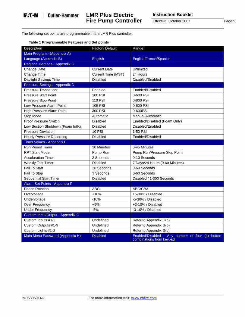
The following set points are programmable in the LMR Plus controller.
Table 1 Programmable Features and Set pointsDescription Factory Default RangeMain Program - (Appendix A) Language (Appendix B) English English/French/SpanishRegional Settings - Appendix CChange Date Current Date UnlimitedChange Time Current Time (MST) 24 HoursDaylight Savings Time Disabled Disabled/EnabledPressure Settings - Appendix DPressure Transducer Enabled Enabled/DisabledPressure Start Point 100 PSI 0-600 PSIPressure Stop Point 110 PSI 0-600 PSILow Pressure Alarm Point 105 PSI 0-600 PSIHigh Pressure Alarm Point 300 PSI 0-600PSIStop Mode Automatic Manual/AutomaticProof Pressure Switch Disabled Enabled/Disabled (Foam Only)Low Suction Shutdown (Foam Intlk) Disabled Disabled/EnabledPressure Deviation 10 PSI 1-50 PSIHourly Pressure Recording Disabled Enabled/DisabledTimer Values - Appendix ERun Period Timer 10 Minutes 0-45 MinutesRPT Start Mode Pump Run Pump Run/Pressure Stop PointAcceleration Timer 2 Seconds 0-10 SecondsWeekly Test Timer Disabled 7 Days/24 Hours (0-60 Minutes)Fail To Start 20 Seconds 0-60 SecondsFail To Stop 3 Seconds 0-60 SecondsSequential Start Timer Disabled Disabled / 1-300 SecondsAlarm Set Points - Appendix FPhase Rotation ABC ABC/CBAOvervoltage +10% +5-30% / DisabledUndervoltage -10% -5-30% / DisabledOver Frequency +5% +3-10% / DisabledUnder Frequency -5% -3-10% / DisabledCustom Input/Output - Appendix GCustom Inputs #1-9 Undefined Refer to Appendix G(a)Custom Outputs #1-9 Undefined Refer to Appendix G(b)Custom Lights #1-2 Undefined Refer to Appendix G(c)Main Menu Password (Appendix H) Disabled Enabled/Disabled - Any number of four (4) button
combinations from keypad

Instruction Booklet LMR Plus Electric Fire Pump ControllerPage 10 Effective: October 2007
For more information visit: www.chfire.com IM05805014K
Following is a description of each programmable setpoint.
Please Enter Password - If the password is enabled,the user will be prompted to enter the password at thistime. If there are no buttons pressed for five (5) seconds,the controller will switch back to the automatic mode.
Language - Three (3) languages are offered asstandard. They are English, French, or Spanish. A fourthlanguage can be added utilizing the USB port. ConsultEaton for available languages. Refer to Appendix B forprogramming.
Regional Settings - Refer to Appendix C. Following arethe descriptions of each menu item:
Change Date - Factory set, however, this parameterallows the user to set the current date.
Change Time - Factory set to Mountain StandardTime (MST). This menu item allows the user toadjust the time to the local time. The clock is of the24-hour type.
Daylight Savings Time - The user is able to enablethe controller to automatically adjust the time fordaylight savings time. On the first Sunday of April itwill move the clock ahead one (1) hour. On the lastSunday of October it will move the clock back one(1) hour.
Pressure Settings - Refer to Appendix D. Following arethe descriptions of each menu item:
Pressure Transmitter - Some applications do notrequire a pressure transmitter to sense the systempressure in order to start the pump motor whenrequired. In order to accomplish this. The pressuretransmitter can be disabled through this menu item.Once disabled, the pressure start point, pressurestop point, low pressure alarm, and high pressurealarm set-points will be removed from the menusystem. Refer to ?4.3 for the Pump Start input to useinstead of the pressure transmitter.
Pressure Start Point - The value programmeddetermines at which pressure the controller willinitiate a start sequence.
Pressure Stop Point - The value programmeddetermines the pressure the system must reachbefore the controller will automatically stop the firepump motor, via the running period timer. If thesystem pressure does not exceed the programmedPressure Stop Point, the fire pump motor willcontinue to run.
Low Pressure Alarm - A low pressure alarm pointcan be selected that will be recorded in thecontroller's history.
High Pressure Alarm - A high pressure alarm pointcan be selected that will be recorded in thecontroller's history.
Stop Mode - The stop mode is user selectable. Ifthe stop mode is programmed for Manual, the pumpmotor must be stopped via the local stoppushbutton, whether or not the motor started via anautomatic start. If the stop mode is programmed forAutomatic, the controller will stop the pump motorautomatically after all starting causes have beenreturned to normal and the running period timer hastimed out.
Proof Pressure Switch - An external pressureswitch will activate the Future #1 input as a startinginput. This menu item will only be active when thecontroller is programmed for a Foam PumpController.
Low Suction Shutdown/Foam Interlock - Thecontroller can be programmed to shutdown when alow suction condition is present. If this is desired,the user will select Enabled. There will also be ashutdown delay timer built in (Range: 0-30 Seconds,Default: 10 Seconds) along with the selection ofeither a Manual or Automatic reset. If Manual Resetis selected, the Ack./Alarm button on the faceplatemust be activated to reset the alarm. If an AutomaticReset (default reset mode) is selected, a delay timer(Range: 0-30 Seconds, Default: 10 Seconds) mustbe set. The controller will then verify if the input isstill active, every time the timer times out. If the inputis still active the timer will reset and count downagain. Once the input has been removed, the timerwill start timing. Once the timer has finished timing,out the controller will return to the automatic runmode. When the shutdown delay timer is timing, thetime left on the timer will be displayed on the fourthline of the display. When the controller is shutdownon Low Suction, the display will read Low SuctionShutdown. The display will also show the automaticreset time delay when timing. Low SuctionShutdown will not work on Local Starts, RemoteStarts, or Emergency Starts.
Pressure Deviation - A pressure setting may beselected, such that any change in pressure greaterthan this setting, will record the pressure fluctuationin the alarm memory.
ATTENTION
NFPA 20, SECTION 2-9.9, SPECIFICALLYPROHIBITS THE INSTALLATION OF ANY DEVICEIN THE SUCTION PIPING THAT WILL RESTRICTSTARTING OR STOPPING OF THE FIRE PUMP.EATON CORPORATION ASSUMES NO LIABILITYWHEN THIS FUNCTION IS USED.

LMR Plus Electric Fire Pump Controller
Instruction BookletEffective: October 2007 Page 11
IM05805014K For more information visit: www.chfire.com
Hourly Pressure Recording - The controller canbe set so that it will take a pressure reading everyhour on the hour. If this feature is not required it canbe disabled by selecting Disabled.
Timer Values - Refer to Figure #6. Following are thedescriptions or each menu item:
Run Period Timer (RPT) - The run period timer isused to automatically stop the controller after aprogrammed time. It can be programmed to operatebased on either of two separate conditions, the stoppressure point or when the pump has started to run.If the RPT is programmed to start at the StopPressure, the timer will start timing once the systempressure has reached the programmed StopPressure Point. If the RPT is programmed to starttiming once the pump is running then the timer willstart timing once the pump has reached a runningcondition. If the Stop Mode is programmed forManual stop the RPT will not be active. It will notstart on Deluge, Remote, Local, and EmergencyStarts. While it is timing the amount of time left onthe timer will be displayed on the fourth line of thedisplay.
RPT Start Mode - The point at which the run periodtimer starts timing is programmable. If it isprogrammed to start timing after the pump hasstarted, the RPT will start timing once 20% of themotor FLA has been reached. If it is programmed tostart timing once the Stop Pressure Point has beenreached, the RPT will start timing when the systempressure has risen above the programmed PressureStop Point.
Acceleration Timer (AT) - The acceleration timercan be programmed to allow the controller to run ina reduced voltage state for a period of time. Thistimer will start timing once a start signal has beenreceived and the startup relay has energized.
Weekly Test Timer - A Weekly Timer can beprogrammed that will automatically start and run thefire pump motor. The Weekly Timer is set byadjusting the day, hour, and minute of the desiredweekly run time, the length of time that this test shallbe performed, and a Test Interval (TI) (Range 1-52Weeks) that will run the test every TI weeks. Whilethe weekly test timer is timing, the remaining timewill be displayed on the fourth line of the display.
Fail To Start Timer (FTS) - The controller will verifythat the motor has reached an amperage ratinggreater that 20% of the programmed motor full loadamps when the pump is running. If the amperagehas not reached 20% of the motor FLA after the FailTo Start timer has timed out the Fail to Start alarmwill be generated.
Fail To Stop Timer - The controller will verify thatthe amperage draw from the motor has dropped
below 20% of the programmed motor full load ampswhen there is a call to stop. If the amperage has notdropped below 20% of the motor FLA, after the FailTo Stop timer has timed out, the Fail to Stop alarmwill be generated.
Sequential Start Timer (SST) - The SST can be setto delay the starting of the pump when a low-pressure condition exists. If, during the timing of thesequential timer, the pressure rises above thepressure start point, the timer will stop timing andthe starting sequence will discontinue. When theSST is timing, the time left will be displayed on thefourth line of the display. The SST will not work onEmergency, Local, Remote, and Deluge Valvestarts.
Alarm Set Points - Refer to Figure #7. Following are thedescriptions or each menu item:
Phase Rotation - The user will be able to changethe Phase Rotation that the program will base thePhase Reversal alarm on.
Overvoltage (OV) - An Overvoltage setting is builtinto the controller. If the system voltage is above thispercentage setting, an alarm will be activated. Thereis a one (1) second delay before alarming onOvervoltage. Once the condition no longer exists,the alarm will automatically clear.
Undervoltage (UV) - An Undervoltage setting isbuilt into the controller. If the system voltage isbelow this percentage setting, an alarm will beactivated. There is a one (1) second delay beforealarming on Undervoltage. Once the condition nolonger exists, the alarm will automatically clear.
Over Frequency (OF) - An Over Frequency settingis built into the controller. If the system frequency isabove this percentage setting, an alarm will beactivated. Once the condition no longer exists thealarm will automatically clear. There is a three (3)second delay before alarming on Over Frequency.
Under Frequency (UF) - An Under Frequencysetting is built into the controller. If the systemfrequency is below this percentage setting, an alarmwill be activated. Once the condition no longer existsthe alarm will automatically clear. There is a three(3) second delay before alarming on UnderFrequency.
Custom Input/Output - Refer to Appendix G. Followingare the descriptions or each menu item:
Custom Inputs - The optional inputs have the ability toprogrammed predetermined values or custom values.The Custom Input Menu will display each input, what it isprogrammed for and if there are any associated optionalrelays and / or lights linked to the input. Refer to Table 2Generic Custom Input Labels for the generic values theoptional inputs can be programmed for. When this input

Instruction Booklet LMR Plus Electric Fire Pump ControllerPage 12 Effective: October 2007
For more information visit: www.chfire.com IM05805014K
is received a message will be stored in memory usingthe programmed label.
Table 2 Generic Custom Input Labels
Load Shed - When the input is programmed forLoad Shed and there is any call to start, exceptremote, local, and emergency start, the program willscan the Transfer Switch Emergency Input, terminal58. If this input is active, the program will energizethe Future #1 relay and delay the start of the motorafter an adjustable timer period. The Load ShedTimer will become active once the Load Shedfunction is enabled. If the emergency input is notactive, the pump will start normally. The load shedrelay will return to its normal state once the timerhas finished timing.
Load Shed Timer - This timer will delay the startingof the motor for a programmed set time as outlinedin the previous item. While timing, the remainingtime will be displayed on the fourth line of thedisplay.
Label - If the input label is set to Custom Input #1,this menu item will become active and allow theuser to enter the desired input name in. The labelwill be limited to 20 characters in length and willinclude all standard ASCII characters.
Energize Common Alarm - If required, thecommon alarm relay (3CR) can be programmed tochange states when this input is received. Defaultvalue is Disabled.
Link to Relay - All inputs can be linked to an outputrelay. If the relay has been linked to another input oris programmed for another alarm, the program willshow that the output is programmed for anotheralarm and ask if the relay should be reassigned.Default value is Disabled.
Link to Light - All inputs can be linked to one of thefuture LED's. If the LED is already linked to anotherinput or is programmed for another alarm, theprogram will show that the LED is programmed for
another alarm and ask if the LED should bereassigned. Default value is Disabled.
Latched Until Reset - The alarm signal can beprogrammed to latch in an on state until the ACK/ALARM or RESET buttons are pressed. In this caseif there are any associated relays or LED's linked tothe input, they will stay active until the ACK/ALARMor RESET buttons are pressed. Default value is No.
Normal Input State - All inputs can be programmedas normally open or normally closed. Default valueis Open.
Timer - A timer can be programmed to delay thetime before the alarm becomes active. Default valueis 0 seconds. Range is 0-500 seconds. The timerwill reset if the input is removed before the time hastimed out.
Custom Outputs - The optional output relays, as well asthe Future #1, relay can be programmed to operatebased on generic values. The Custom Output Menu willdisplay each output, what it is programmed for and ifthere are any associated future inputs and / or lightslinked to the output. Please refer to Table 3 for thegeneric values the optional outputs can be programmedfor. Following is a description of the menu items in theCustom Outputs menu.
Table 3 Generic Outputs
InputCustom Input #1Relief Valve DischargeLoad ShedEmergency Switch OpenJockey Pump RunSecondary Pump RunLow ReservoirHigh ReservoirPump Room Door OpenSupervisory Power FailGenerator Disconnected
AlarmLow PressureHigh PressureOvervoltageUndervoltageLow SuctionInterlock OnFail To StartPump RunningMotor OverloadWeekly Test StartCall to StartOver FrequencyUnder FrequencyLocal StartRemote StartDeluge StartEmergency StartLow Pressure StartPump StartRPT TimingSequential Start TimingTransducer FailureBackup Battery LowLow Room TempFail to Stop

LMR Plus Electric Fire Pump Controller
Instruction BookletEffective: October 2007 Page 13
IM05805014K For more information visit: www.chfire.com
Latched Until Reset - Output relays can be set aslatching relays. Pressing the ACK/ALARM orRESET buttons will unlatch them. Default value isNo.
Fail Safe - Output relays can be programmed toenergize under normal conditions (fail safe) or de-energize under normal conditions. Default value isNo.
Timer - Each output relay can be programmed as atime delay relay. Either as an On delay or as an Offdelay. If it is set for On Delay (default) the relay willdelay for the programmed time prior to activating therelay. If it is set for Off Delay the relay will activatethe relay instantly and then de-activate it after theprogrammed time.
Custom Lights - The two (2) optional LED's can beprogrammed for alarms that do not have an associatedLED or one of the custom inputs. In this section of theprogram, the LED's can be programmed for one of thevalues listed in Table 4. As a default the LED's will beprogrammed for Undefined.
Table 4 Custom Lights
6. HISTORY, DIAGNOSTICS AND STATISTICSThe LMR Plus controller will record a number of items inits memory to assist with troubleshooting of the systemand/or the fire pump controller.
These include system history, system statistics, andcontroller diagnostics.
6.1 System History
The LMR Plus controller will record the last 5000 alarm/status messages in its memory that can be viewed onthe main display, saved to a USB disk drive, or viewedon the embedded webpage.
In order to view the messages on the display press theup or down arrow buttons from the main screen until thedisplay shows "Display Last Messages". Press the Ack.Alarm button to view the message history. The displaywill now show three messages at a time. Pressing the upor down arrow buttons will allow navigation showing the
most recent message to the oldest message. Refer toAppendix K for common messages and their meaning.
Refer to Section ?7 to save the message history to aUSB disk drive or to view the message history on theembedded webpage.
6.2 Statistics
The LMR Plus controller will record a number ofstatistical points for a quick review of how the systemhas been operating. The statistics can be viewed on themain display, saved to a USB disk drive, or viewed onthe embedded webpage.
In order to view the statistics on the display press the upor down arrow buttons from the main screen until thedisplay shows "Controller Statistics". Press the Ack.Alarm button to view the statistics. The display will showthe statistics that the controller has recorded. Refer toTable 5 for the statistics included with the controller.
Refer to Section 7 to save the controller statistics to aUSB disk drive or to view the message history on theembedded webpage.
Table 5 Controller Statistics
6.3 Controller Diagnostics
The LMR Plus controller has a number of diagnosticpoints that can be used to help in troubleshooting issueswith the controller. The diagnostics can be viewed on themain display, saved to a USB disk drive, or viewed onthe embedded webpage.
In order to view the diagnostics on the display press theup or down arrow buttons from the main screen until thedisplay shows "Controller Diagnostics". Press the Ack.Alarm button to view the diagnostics. The display will
AlarmHigh PressureMotor OverloadWeekly Test TimingOver FrequencyUnder FrequencyRPT TimingSequential Start TimingTransducer FailurePump StartBattery Backup LowFail to Stop
Statistic RangePowered Time 000000.0-999999.9Motor Run Time 00000.0-99999.9Number of Calls to Start 00000-99999Number of Starts 00000-99999Last Motor Start Date & TimeLast Motor Run Time 0000.0-9999.9Last Low Pressure Start Date & TimeMinimum System Voltage UnlimitedMaximum System Voltage UnlimitedMinimum System Frequency UnlimitedMaximum System Frequency UnlimitedMinimum System Pressure UnlimitedMaximum System Pressure UnlimitedLast System Startup Date & TimeLast Phase Failure Date & TimeLast Phase Reversal Date & TimeLast Locked Rotor Trip Date & TimeMaximum Run Current UnlimitedLast Locked Rotor Current Unlimited

Instruction Booklet LMR Plus Electric Fire Pump ControllerPage 14 Effective: October 2007
For more information visit: www.chfire.com IM05805014K
show the diagnostics. In order to navigate thediagnostics use the up or down arrow buttons.
Note: The diagnostic information shall be provided topersonnel trained in the meaning of the values shown.
Diagnostic values that are recorded are the current dataand time, the microprocessor's firmware version, Eaton'sshop order number, customer shop order number,voltage readings, current transformer readings, pressuretransducer readings, input status, and output status.
Refer to Section 7 to save the controller diagnostics to aUSB disk drive or to view the message history on theembedded webpage.
7. COMMUNICATIONThe LMR Plus controller comes complete with a numberof communication protocols that can be used for thecollection of information that the controller has seen.
The communication protocols that are included with thecontroller are USB and Ethernet.
The ports included with the controller are USB, Ethernet,and RS485.
7.1 USB
The USB port is used to download the message history,controller statistics, controller diagnostics, and status toa USB disk drive. The USB port can also be used toupload custom messages, additional languages, andupdate the microprocessor firmware.
Information Download
In order to download the history, diagnostics,statistics, and status, install a USB disk drive intothe USB port on the display board. With the poweron, press the Data | Print button. The first selectionis "Save to USB". Press the Ack. Alarm button andthe controller will save the information to the USBdisk drive.
There will be four (4) files saved to the disk drive.Refer to Table 6 for the file nomenclature.
Table 6 File Nomenclature
The .csv file is a comma separated values file thatcan be opened using standard spreadsheet, wordprocessor, or database programs. The .txt files canbe opened using standard text viewers.
Custom Message Upload
The LMR Plus controller has the ability to store anduse up to ten (10) custom messages that canappear based on a specific date, time, alarm orstatus condition.
Refer to Appendix J to upload and enable thecustom messages.
Refer to Section 8 for the creation of the custommessage file.
Firmware Update
Contact the factory or an authorized trainedrepresentative for assistance.
Language Upload
Contact the factory or an authorized trainedrepresentative for assistance.
7.2 Embedded Webpage
The controller has a built-in webpage that can be used toview the main display of the controller and its currentstatus.
Contact the factory or an authorized trainedrepresentative for assistance in accessing the webpage.
7.3 RS485 Serial Port
This port is reserved for future communication withexternal building management systems requiring specificcommunication protocols. Contact the factory foravailability.
7.4 RS232 Serial Port
This port is used with the optional printer (X1) to initiate aprint cycle.
8. CUSTOM MESSAGESIn order to upload custom messages to the controller afile needs to be created. This section outlines the fileformat and trigger points required to use the custommessages.
All that is required to create the custom message file is astandard spreadsheet program. Specific software is notrequired.
Ten (10) custom messages can be saved in the file anduploaded to the controller for use. Each message will beentered in the first ten (10) rows of the spreadsheet. Donot use the top row as a heading row.
There are five (5) trigger points that can be used. Theyinclude specific date and time range, number of pumpstart events, number of hours run, specific alarms, orcommon alarm.
File Nomenclature DescriptionARC00000.csv ARC=Archive
00000=Serial numberMessagehistory
STC00000.txt STC=Statistics00000=Serial number
Controllerstatistics
DIA00000.txt DIA=Diagnostics00000=Serial number
Controllerdiagnostics
STA00000.txt STA=Statistics00000=Serial number
Controllerstatus

LMR Plus Electric Fire Pump Controller
Instruction BookletEffective: October 2007 Page 15
IM05805014K For more information visit: www.chfire.com
Figure 1 shows examples of the custom messages andhow the file needs to be laid out. Following is adescription of each column and the data required to beentered in the column.
Figure 1 Custom Message Examples
Column A contains the message that will scroll along thefourth line of the display. The message can be up to onehundred (100) characters in length.
Column B contains the message type reference number.Refer to Table 7 for the message types.
Table 7 Custom Message Types
Column C and D are used to determine when the custommessage will appear. Refer to the following for specificnotes regarding each tripper point.
Date and Time Range (1)
Column C is used for the date and time that the messagewill start and column D is used for the date and time thatthe message will stop.
The date and time format is as follows:
MMDDYYHHMM = Month Day Year Hour Minute
If any value entered between 1 and 9 needs to be leadby a 0. For example, January 1, 2007, 8:15AM needs tobe entered as 0101070815.
Note: All cells need to be formatted as text.
Number of Pump Start Events (2)
Column C is used to enter the number of pump startsbefore the message will appear.
The format is as follows:
XXXXX = Number of Pump Start Events
For example to have the message appear after 25 pumpstart events it will be entered as 00025.
Note: All cells need to be formatted as text.
Number of Hours Run (3)
Column C is used to enter the number of hours the pumphas run before the message will appear.
The format is as follows:
XXXXX = Number of Hours Run
For example, to have the message appear after 125hours of running the trigger point will be entered as00125.
Note: All cells need to be formatted as text.
Specific Alarms (4)
Column C is used to enter the alarm event number.Refer to Table 8 for the alarm events and theircorresponding number.
Table 8 Specific Alarm Events
Note: All cells needs to be formatted as text.
Common Alarm (5)
No other points are required to be entered into thespreadsheet, as this message will appear anytime thereis an alarm.
Number Description1 Specific date and time range2 Number of pump start events3 Number of hours run4 Specific alarms5 Common Alarms
Number Event01 Overvoltage (Phase A, B, or C)02 Undervoltage (Phase A, B, or C)03 Phase Failure (Phase A, B, or C)04 Phase Reversal05 Low Suction06 Relief Valve Open07 Fail to Stop08 Fail to Start09 Locked Rotor Trip10 Deluge Valve Off11 Low Foam Level12 Low Pressure13 Low Room Temperature14 Over Frequency15 Under Frequency16 Transducer Failure

Instruction Booklet LMR Plus Electric Fire Pump ControllerPage 16 Effective: October 2007
For more information visit: www.chfire.com IM05805014K
APPENDIX A: MAIN MENU TREE
MENU PASSWORD
ACK
LANGUAGE
REGIONAL SETTINGS
PRESSURE SETTINGS
TIMER VALUES
ALARM SET POINTS
CUSTOM INPUT/OUTPUT
SYSTEM CONFIG MENU
MAIN MENU PASSWORD
ACK
ACK
ACK
ACK
ACK
ACK
ACK
ACK
GO TO APPENDIX B
GO TO APPENDIX C
GO TO APPENDIX D
GO TO APPENDIX E
GO TO APPENDIX F
GO TO APPENDIX G
CONSULT FACTORY
GO TO APPENDIX H

LMR Plus Electric Fire Pump Controller
Instruction BookletEffective: October 2007 Page 17
IM05805014K For more information visit: www.chfire.com
APPENDIX B: LANGUAGE MENU TREE
ACK
LANGUAGE
ACK
SELECT LANGUAGE
MENU

Instruction Booklet LMR Plus Electric Fire Pump ControllerPage 18 Effective: October 2007
For more information visit: www.chfire.com IM05805014K
APPENDIX C: REGIONAL SETTINGS MENU TREE
MENU
MENU
MENU
ACK
ACK
ACK
ACK
ACK
ACK
ACK
ACK
ACK
ACK
REGIONAL SETTING
ACK
CHANGE DATE
CHANGE TIME
DAYLIGHT SAVINGS
SET MONTH
SET HOUR
SET DAYLIGHT SAVINGS
SET DAY
SET MINUTES
NEXT MENU ITEM
NEXT MENU ITEM
NEXT MENU ITEMNEXT MENU
ITEM
SET YEAR SET DAY OF WEEK

LMR Plus Electric Fire Pump Controller
Instruction BookletEffective: October 2007 Page 19
IM05805014K For more information visit: www.chfire.com
APPENDIX D: PRESSURE SETTINGS MENU TREE
MENU
MENU
MENU
MENU
MENU
MENU
MENU
MENU
MENU
MENU
ACK
ACK
ACK
ACK
ACK
ACK
ACK
ACK
ACK
ACK
ACK
ACK
ACK
ACK
ACK
ACK
ACK
ACK
ACK
ACK
ACK ACK
ACK
NEXT MENU ITEM
NEXT MENU ITEM
NEXT MENU ITEM
NEXT MENU ITEM
NEXT MENU ITEM
NEXT MENU ITEM
NEXT MENU ITEM
NEXT MENU ITEM
NEXT MENU ITEM
PRESSURE SETTINGS
ACK
PRESSURE TRANSMITTER
PRESSURE START POINT
PRESSURE STOP POINT
LOW PRESSURE
ALARM
HIGH PRESSURE
ALARM
STOP MODE
PROOF PRESSURE
SWITCH
LOW SUCTION SHUTDOWN
PRESSURE DEVIATION
HOURLY PRESSURE
RECORDING
NEXT MENU ITEM
SET PRESSURE
TRANSMITTER
SET START PRESSURE
SET STOP PRESSURE
SET LOW PRESSURE
ALARM
SET HIGH PRESSURE
ALARM
SET STOP MODE
SET PROOF PRESSURE
SWITCH
SET LOW SUCTION
SHUTDOWN
SET PRESSURE DEVIATION
SET HOURLY PRESSURE
RECORDING
SET SHUTDOWN
DELAYSET RESET
MODESET
AUTOMATIC RESET TIME
ENABLED ON FOAM SYSTEMS ONLY
NEXT MENU ITEM

Instruction Booklet LMR Plus Electric Fire Pump ControllerPage 20 Effective: October 2007
For more information visit: www.chfire.com IM05805014K
APPENDIX E: TIMER VALUES MENU TREE
MENU
MENU
MENU
MENU
MENU
MENU
MENU
ACK
ACK
ACK
ACK
ACK
ACK
ACK
ACK
ACK
ACK
ACK
ACK
ACK
ACK
ACK ACK
ACK
NEXT MENU ITEM
NEXT MENU ITEM
NEXT MENU ITEM
NEXT MENU ITEM
NEXT MENU ITEM
TIMER VALUES
ACK
RUN PERIOD TIMER
RPT START MODE
ACCELERATION TIMER
WEEKLY TEST TIMER
FAIL TO START TIMER
FAIL TO STOP TIMER
SEQUENTIAL START TIMER
SET RUN PERIOD TIMER
SET RPT START MODE
SET ACCELERATION
TIMER
SET WEEKLY TEST TIMER
SET FAIL TO START TIMER
SET FAIL TO STOP TIMER
SET SEQUENTIAL START TIMER
SET DAY SET TIME SET TEST INTERVAL
NEXT MENU ITEM
ACK
SET RUN TIME
NEXT MENU ITEM
LMR Plus Electric Fire Pump Controller
Instruction BookletEffective: October 2007 Page 21
IM05805014K For more information visit: www.chfire.com
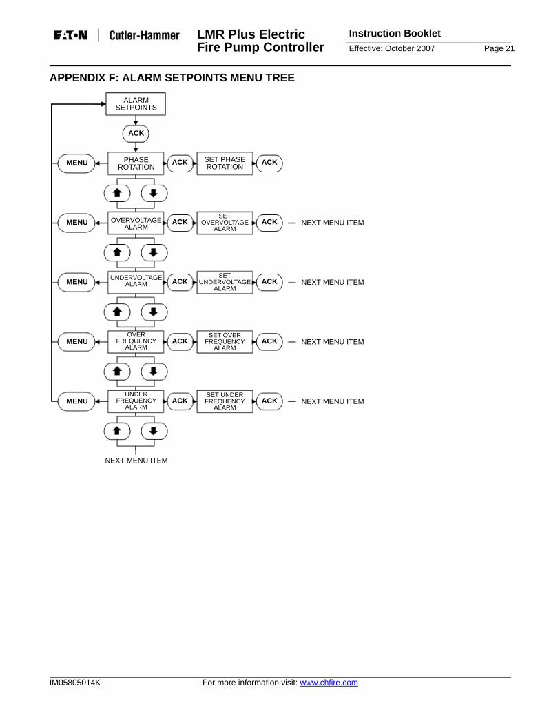
APPENDIX F: ALARM SETPOINTS MENU TREE
MENU
MENU
MENU
MENU
MENU
ACK
ACK
ACK
ACK
ACK
ALARM SETPOINTS
ACK
PHASE ROTATION
OVERVOLTAGE ALARM
UNDERVOLTAGE ALARM
OVER FREQUENCY
ALARM
UNDER FREQUENCY
ALARM
SET PHASE ROTATION
SET OVERVOLTAGE
ALARM
SET UNDERVOLTAGE
ALARM
SET OVER FREQUENCY
ALARM
SET UNDER FREQUENCY
ALARM
NEXT MENU ITEM
NEXT MENU ITEM
NEXT MENU ITEM
NEXT MENU ITEM
NEXT MENU ITEM
ACK
ACK
ACK
ACK
ACK

Instruction Booklet LMR Plus Electric Fire Pump ControllerPage 22 Effective: October 2007
For more information visit: www.chfire.com IM05805014K
APPENDIX G: CUSTOM INPUT/OUTPUT MENU TREE
MENU
MENU
MENU
ACK
ACK
ACK
CUSTOM INPUT/OUTPUT
ACK
CUSTOM INPUTS
CUSTOM OUTPUTS
CUSTOM LIGHTS
NEXT MENU ITEM
GO TO APPENDIX G(a)
GO TO APPENDIX G(b)
GO TO APPENDIX G(c)

LMR Plus Electric Fire Pump Controller
Instruction BookletEffective: October 2007 Page 23
IM05805014K For more information visit: www.chfire.com
APPENDIX G(A): CUSTOM INPUTS MENU TREE
MENU
MENU
MENU
MENU
MENU
MENU
MENU
MENU
MENU
ACK
ACK
ACK
ACK
ACK
ACK
ACK ACK
NEXT MENU ITEM
NEXT MENU ITEM
NEXT MENU ITEM
NEXT MENU ITEM
NEXT MENU ITEM
NEXT MENU ITEM
CUSTOM INPUTS
ACK
SELECT INPUT
ACK
SELECT INPUT TYPE
ACK
INPUT LABEL
COMMON ALARM RELAY
LINK TO RELAY
LINK TO LIGHT
LATCH
NORMAL INPUT STATE
DELAY TIMER
SET INPUT LABEL
SET COMMON ALARM RELAY
SET LINK TO RELAY
SET LINK TO LIGHT
SET LATCH
SET NORMAL INPUT STATE
SET DELAY TIMER
SET DELAY TIME
NEXT MENU ITEM
ACK
ACK
ACK
ACK
ACK
ACK
ACK NEXT MENU ITEM
Instruction Booklet LMR Plus Electric Fire Pump ControllerPage 24 Effective: October 2007
For more information visit: www.chfire.com IM05805014K
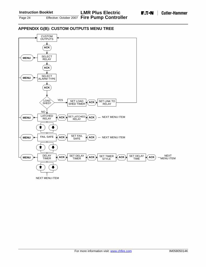
APPENDIX G(B): CUSTOM OUTPUTS MENU TREE
MENU
MENU
MENU
MENU
MENU
ACK
ACK
ACK ACK
NEXT MENU ITEM
NEXT MENU ITEM
CUSTOM OUTPUTS
ACK
SELECT RELAY
ACK
SELECT ALARM TYPE
ACK
LOAD SHED?
NOLATCHED
RELAY
FAIL SAFE
DELAY TIMER
SET LOAD SHED TIMER
SET LATCHED RELAY
SET FAIL SAFE
SET DELAY TIMER
SET LINK TO RELAY
NEXT MENU ITEM
NEXT MENU ITEM
ACK
ACK
ACK
ACK
YES
SET TIMER STYLE
SET DELAY TIME ACK
LMR Plus Electric Fire Pump Controller
Instruction BookletEffective: October 2007 Page 25
IM05805014K For more information visit: www.chfire.com
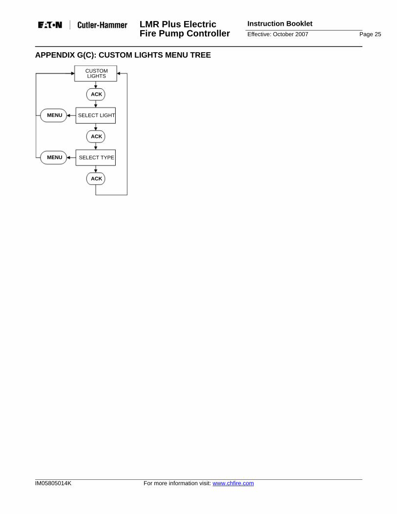
APPENDIX G(C): CUSTOM LIGHTS MENU TREE
MENU
MENU
CUSTOM LIGHTS
ACK
SELECT LIGHT
ACK
SELECT TYPE
ACK

Instruction Booklet LMR Plus Electric Fire Pump ControllerPage 26 Effective: October 2007
For more information visit: www.chfire.com IM05805014K
APPENDIX H: MAIN MENU PASSWORD MENU TREE
MENU MAIN MENU PASSWORD
ACK
SELECT PASSWORD ACK SELECT
BUTTON #1SELECT
BUTTON #2SELECT
BUTTON #3SELECT
BUTTON #4

LMR Plus Electric Fire Pump Controller
Instruction BookletEffective: October 2007 Page 27
IM05805014K For more information visit: www.chfire.com
APPENDIX J: CUSTOM MESSAGE LOAD & ACTIVATION
DATASELECT CUSTOM
MESSAGES
ACK
SELECT LOAD ACKCUSTOM
MESSAGES WILL BE UPLOADED
DATA SELECT CUSTOM
MESSAGES
ACK
SELECT VIEW ACKCUSTOM
MESSAGE TO ENABLE/DISABLE
ACK ACK
MENU
SELECT ENABLE/DISABLE
Instruction Booklet LMR Plus Electric Fire Pump ControllerPage 28 Effective: October 2007
For more information visit: www.chfire.com IM05805014K
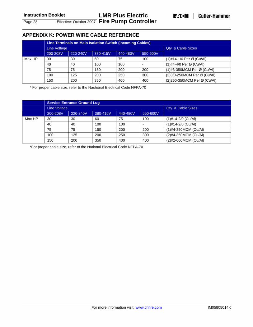
APPENDIX K: POWER WIRE CABLE REFERENCE
* For proper cable size, refer to the Naotional Electrical Code NFPA-70
*For proper cable size, refer to the National Electrical Code NFPA-70
Line Terminals on Main Isolation Switch (incoming Cables)Line Voltage Qty. & Cable Sizes200-208V 220-240V 380-415V 440-480V 550-600V
Max HP 30 30 60 75 100 (1)#14-1/0 Per Ø (Cu/Al)40 40 100 100 - (1)#4-4/0 Per Ø (Cu/Al)75 75 150 200 200 (1)#3-350MCM Per Ø (Cu/Al)100 125 200 250 300 (2)3/0-250MCM Per Ø (Cu/Al)150 200 350 400 400 (2)250-350MCM Per Ø (Cu/Al)
Service Entrance Ground LugLine Voltage Qty. & Cable Sizes200-208V 220-240V 380-415V 440-480V 550-600V
Max HP 30 30 60 75 100 (1)#14-2/0 (Cu/Al)40 40 100 100 - (1)#14-2/0 (Cu/Al)75 75 150 200 200 (1)#4-350MCM (Cu/Al)100 125 200 250 300 (2)#4-350MCM (Cu/Al)150 200 350 400 400 (2)#2-600MCM (Cu/Al)

LMR Plus Electric Fire Pump Controller
Instruction BookletEffective: October 2007 Page 29
IM05805014K For more information visit: www.chfire.com
APPENDIX L: ALARM/STATUS MESSAGESMessage DescriptionATS IN EMERGENCY The automatic transfer switch is in the emergency positionATS IN NORMAL The automatic transfer switch is in the normal positionBACKUP BATTERY LOW The battery used to maintain the date and time when power is not applied to the controller
has a low voltage condition and should be replacedDELUGE VALVE START The controller started the motor after it received a deluge valve start signalEMERGENCY START The emergency start handle was pressed in and the motor startedFAIL TO START There was a call to start the motor, however, the amperage draw did not reach 20% of the
programmed motor full load ampsFAIL TO STOP If the amperage draw has not dropped below 20% of the programmed motor full load amps
two (2) seconds after a stop command, this alarm will be triggeredFREQUENCY OK The system frequency has come back into normal operating levels and the alarm has been
clearedGENERATOR DISCONNECT The isolation switch on the automatic power transfer switch is in the open positionHIGH PRESSURE The system pressure is above the programmed high pressure alarm set pointINTERLOCK OFF The interlock signal has been removedINTERLOCK ON The interlock signal has been receivedINTERLOCK SHUTDOWN The pump has been shutdown due to an interlock signalJOCKEY RUNNING The jockey pump running signal has been receivedJOCKEY STOPPED The jockey pump running signal has been removedLOAD SHED CLOSED The load shed timer has started timing and the load shed output has closedLOCAL START The start pushbutton on the enclosure flange was pressed initiating a start sequenceLOCAL STOP The stop pushbutton on the enclosure flange was pressed initiating a stop sequenceLOCKED ROTOR TRIP The controller has tripped on the built in locked rotor over current protectionLOW FOAM INTERLOCK The controller has shutdown after receiving a low foam level signalLOW FOAM LEVEL The controller has received a low foam level signalLOW PRESSURE The system pressure has dropped below the programmed pressure start pointLOW PRESSURE ALARM The system pressure has dropped below the programmed low pressure alarm pointLOW PRESSURE OK The system pressure has risen above the programmed pressure stop pointLOW PRESSURE START The pump has started running because of a low pressure conditionLOW ROOM TEMPERATURE The controller has received a low room temperature signalLOW SUCTION The controller has received a low suction signalLOW SUCTION SHUTDOWN The controller has shutdown because of low suctionMENU ENTERED The menu system was entered by a userMOTOR OVERLOAD The amperage draw has exceeded 125% of the programmed motor full load ampsOV PHASE AB The voltage measured between phase A and B has exceeded the programmed
overvoltage alarm set pointOV PHASE BC The voltage measured between phase B and C has exceeded the programmed
overvoltage alarm set pointOV PHASE CA The voltage measured between phase C and A has exceeded the programmed
overvoltage alarm set pointOVER FREQ The system frequency has exceeded the programmed over frequency set pointPHASE A FAILURE The controller has detected a phase failure on phase APHASE A OK The phase failure alarm detected on phase A has been clearedPHASE B FAILURE The controller has detected a phase failure on phase BPHASE B OK The phase failure alarm detected on phase B has been clearedPHASE C FAILURE The controller has detected a phase failure on phase CPHASE C OK The phase failure alarm detected on phase C has been clearedPHASE REVERSAL The controller has detected a phase reversal on the system voltagePHASE REVERSAL OK The phase reversal alarm has been cleared

Instruction Booklet LMR Plus Electric Fire Pump ControllerPage 30 Effective: October 2007
For more information visit: www.chfire.com IM05805014K
PRESSURE = 000 System pressure readings the controller has recorded PUMP RUNNING The amperage draw on the motor has reached at least 20% of the programmed motor full
load ampsPUMP START The pump has started via a pump start signalPUMP START OFF The pump start signal has been removedPUMP STOPPED The pump has stopped after a stop sequence has been initiatedREMOTE START The pump has stated via a remote start signalROOM TEMPERATURE OK The low room temperature alarm has clearedRPT TIMED OUT The running period timer has finished its timing cycleSEQ START DELAY A start sequence has been started, however, it is delayed due to the programmed
sequential start timerSST STOPPED The sequential start timer has stopped timingSYSTEM STARTUP Power has been reapplied to the system and a successful system boot has been
completedTRANSDUCER FAILURE The controller has detected that the transducer has failedTRANSDUCER OK The controller has detected that the transducer is in good working conditionUV PHASE AB The voltage measured between phases A and B has dropped below the programmed
undervoltage set pointUV PHASE BC The voltage measured between phases B and C has dropped below the programmed
undervoltage set pointUV PHASE CA The voltage measured between phases C and A has dropped below the programmed
undervoltage set pointWEEKLY TEST DONE The weekly test has been completedWEEKLY TEST START The pump has started on a weekly testWEEKLY TEST STOP The pump has stopped after a weekly test cycle
Message Description
LMR Plus Electric Fire Pump Controller
Instruction BookletEffective: October 2007 Page 31
IM05805014K For more information visit: www.chfire.com
NOTES:

Instruction Booklet LMR Plus Electric Fire Pump ControllerPage 32 Effective: October 2007
For more information visit: www.chfire.com IM05805014K
NOTES:

LMR Plus Electric Fire Pump Controller
Instruction BookletEffective: October 2007 Page 33
IM05805014K For more information visit: www.chfire.com
This information booklet is published solely forinformation purposes and should not be considered all-inclusive. If further information is required, you shouldconsult EATON.
Sale of product shown in this literature is subject to termsand conditions outlined in appropriate EATON sellingpolices or other contractual agreement between theparties. This literature is not intended to and does notenlarge or add to any such contract. The sole sourcegoverning the rights and remedies of any purchaser ofthis equipment is the contract between the purchaserand EATON.
NO WARRANTIES, EXPRESSED OR IMPLIED,INCLUDING WARRANTIES OF FITNESS FOR APARTICULAR PURPOSE OR MERCHANTABILITY, ORWARRANTIES ARISING FROM COURSE OF DEALINGOR USAGE OF TRADE, ARE MADE REGARDING THEINFORMATION, RECOMMENDATIONS ANDDESCRIPTIONS CONTAINED HEREIN. In no event willEATON be responsible to the purchaser or user incontract, in tort (including negligence), strict liability orotherwise for any special, indirect, incidental orconsequential damage or loss whatsoever, including butnot limited to damage or loss of use of equipment, plantor power system, cost of capital, loss of power, additionalexpenses in the use of existing power facilities, or claimsagainst the purchaser or user by its information,recommendations and description contained herein.

EATON2256 29th Street NE #10Calgary, Alberta, T1Y 7G4CanadaTel: 403-717-2000Fax: 403-717-0567www.chfire.com
© 2007 Eaton CorporationAll Rights ReservedPrinted in CanadaPublication No.: IM05805014KOctober 2007
Related Documents