Ž . Mechanics of Materials 27 1998 91–110 Effects of thermal gradient and residual stresses on thermal barrier coating fracture G. Qian a , T. Nakamura a, ) , C.C. Berndt b a Department of Mechanical Engineering, State UniÕersity of New York, Stony Brook, NY 11794, USA b Department of Materials Science and Engineering, State UniÕersity of New York, Stony Brook, NY 11794, USA Received 5 May 1997; received in revised form 15 September 1997 Abstract Driving mechanisms which lead to internal crack growth and failure in the thermally sprayed coatings are identified using detailed finite element models. Coatings are assumed to contain embedded cracks and they are thermally loaded according to a typical high temperature environment. In order to determine the accurate stress state, the thermal gradient within the coating is calculated from the steady-state heat transfer analysis. Our models take into account various locations of cracks, temperature-dependent and -independent plasticity, thermal conductivities of different layers and thermal insulation across crack surfaces. The results indicate that the energy release rate of large cracks can reach close to fracture toughness of ceramic coatings. We have also studied the effect of residual stresses on the fracture behavior. For a penny-shaped crack located parallel to the coating layers, a limited influence of residual stresses is observed. The effect is more pronounced when the crack orientation is perpendicular to the coating layers where it has shown a beneficial influence. In both cases, the effects of residual stresses are relevant to the cracks close to the ceramic–bond interface. In addition, we have modeled functionally graded material and investigated its mechanical influence on the embedded cracks. The implications of the present work to internal crack initiation and growth, which can lead to coating failure, are also addressed. q 1998 Elsevier Science Ltd. 1. Introduction Ž . Thermal barrier coatings TBCs sprayed onto a substrate provide high temperature protection to ma- chine parts and improve their efficiency. In recent years, industrial applications of various TBCs have Ž increased significantly Liebert and Miller, 1984; ) Corresponding author. E-mail: [email protected]. . Miller, 1997 . One of more common fabrication techniques is plasma spray processing where ceramic powder is melted and sprayed onto a substrate. This process renders a unique microstructure consisting of voids and defects within a porous coating mi- crostructure. Moreover, many coating material prop- erties differ from those of the corresponding bulk materials. For example, the elastic modulus of zirco- nia-based coatings is only about one fourth of that of Ž bulk zirconia Herman and Shankar, 1987; McPher- . son, 1989; Bengtsson and Johannesson, 1995 . 0167-6636r98r$19.00 q 1998 Elsevier Science Ltd. All rights reserved. Ž . PII S0167-6636 97 00042-2

Welcome message from author
This document is posted to help you gain knowledge. Please leave a comment to let me know what you think about it! Share it to your friends and learn new things together.
Transcript
Ž .Mechanics of Materials 27 1998 91–110
Effects of thermal gradient and residual stresses on thermalbarrier coating fracture
G. Qian a, T. Nakamura a,), C.C. Berndt b
a Department of Mechanical Engineering, State UniÕersity of New York, Stony Brook, NY 11794, USAb Department of Materials Science and Engineering, State UniÕersity of New York, Stony Brook, NY 11794, USA
Received 5 May 1997; received in revised form 15 September 1997
Abstract
Driving mechanisms which lead to internal crack growth and failure in the thermally sprayed coatings are identified usingdetailed finite element models. Coatings are assumed to contain embedded cracks and they are thermally loaded according toa typical high temperature environment. In order to determine the accurate stress state, the thermal gradient within thecoating is calculated from the steady-state heat transfer analysis. Our models take into account various locations of cracks,temperature-dependent and -independent plasticity, thermal conductivities of different layers and thermal insulation acrosscrack surfaces. The results indicate that the energy release rate of large cracks can reach close to fracture toughness ofceramic coatings. We have also studied the effect of residual stresses on the fracture behavior. For a penny-shaped cracklocated parallel to the coating layers, a limited influence of residual stresses is observed. The effect is more pronouncedwhen the crack orientation is perpendicular to the coating layers where it has shown a beneficial influence. In both cases, theeffects of residual stresses are relevant to the cracks close to the ceramic–bond interface. In addition, we have modeledfunctionally graded material and investigated its mechanical influence on the embedded cracks. The implications of thepresent work to internal crack initiation and growth, which can lead to coating failure, are also addressed. q 1998 ElsevierScience Ltd.
1. Introduction
Ž .Thermal barrier coatings TBCs sprayed onto asubstrate provide high temperature protection to ma-chine parts and improve their efficiency. In recentyears, industrial applications of various TBCs have
Žincreased significantly Liebert and Miller, 1984;
) Corresponding author. E-mail:[email protected].
.Miller, 1997 . One of more common fabricationtechniques is plasma spray processing where ceramicpowder is melted and sprayed onto a substrate. Thisprocess renders a unique microstructure consisting ofvoids and defects within a porous coating mi-crostructure. Moreover, many coating material prop-erties differ from those of the corresponding bulkmaterials. For example, the elastic modulus of zirco-nia-based coatings is only about one fourth of that of
Žbulk zirconia Herman and Shankar, 1987; McPher-.son, 1989; Bengtsson and Johannesson, 1995 .
0167-6636r98r$19.00 q 1998 Elsevier Science Ltd. All rights reserved.Ž .PII S0167-6636 97 00042-2
( )G. Qian et al.rMechanics of Materials 27 1998 91–11092
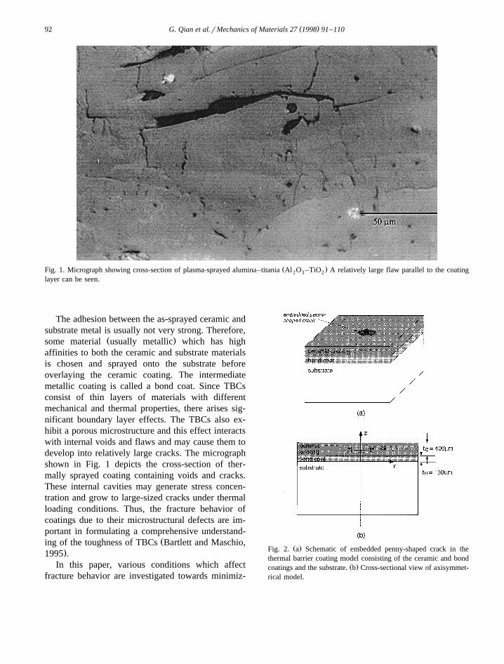
Ž .Fig. 1. Micrograph showing cross-section of plasma-sprayed alumina–titania Al O –TiO A relatively large flaw parallel to the coating2 3 2
layer can be seen.
The adhesion between the as-sprayed ceramic andsubstrate metal is usually not very strong. Therefore,
Ž .some material usually metallic which has highaffinities to both the ceramic and substrate materialsis chosen and sprayed onto the substrate beforeoverlaying the ceramic coating. The intermediatemetallic coating is called a bond coat. Since TBCsconsist of thin layers of materials with differentmechanical and thermal properties, there arises sig-nificant boundary layer effects. The TBCs also ex-hibit a porous microstructure and this effect interactswith internal voids and flaws and may cause them todevelop into relatively large cracks. The micrographshown in Fig. 1 depicts the cross-section of ther-mally sprayed coating containing voids and cracks.These internal cavities may generate stress concen-tration and grow to large-sized cracks under thermalloading conditions. Thus, the fracture behavior ofcoatings due to their microstructural defects are im-portant in formulating a comprehensive understand-
Žing of the toughness of TBCs Bartlett and Maschio,.1995 .
In this paper, various conditions which affectfracture behavior are investigated towards minimiz-
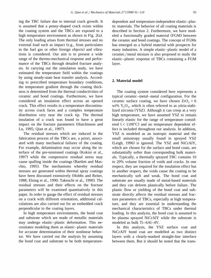
Ž .Fig. 2. a Schematic of embedded penny-shaped crack in thethermal barrier coating model consisting of the ceramic and bond
Ž .coatings and the substrate. b Cross-sectional view of axisymmet-rical model.
( )G. Qian et al.rMechanics of Materials 27 1998 91–110 93
ing the TBC failure due to internal crack growth. Itis assumed that a penny-shaped crack exists withinthe coating system and the TBCs are exposed to a
Ž .high temperature environment as shown in Fig. 2 a .The only loading arises from thermal stresses and no
Žexternal load such as impact e.g., from particulates.in the fuel gas or other foreign objects and vibra-
tions is considered. Our aim is to present a widerange of the thermo-mechanical response and perfor-mance of the TBCs through detailed fracture analy-sis. In carrying out the simulation study, we haveestimated the temperature field within the coatingsby using steady-state heat transfer analysis. Accord-ing to prescribed temperature boundary conditions,the temperature gradient through the coating thick-ness is determined from the thermal conductivities ofceramic and bond coatings. Furthermore, we haveconsidered an insulation effect across an openedcrack. This effect results in a temperature discontinu-ity across crack faces and a complex temperaturedistribution very near the crack tip. The thermalinsulation of a crack was found to have a great
Žimpact on the fracture parameters Hutchinson and.Lu, 1995; Qian et al., 1997 .
The residual stresses which are induced in thefabrication process of the TBCs are, a priori, associ-ated with many mechanical failures of the coating.For example, delamination may occur along the in-
Žterface of the pre-tensioned coatings Kokini et al.,.1997 while the compressive residual stress may
Žcause spalling inside the coatings Bartlett and Mas-.chio, 1995 . The mechanisms whereby residual
stresses are generated within thermal spray coatingsŽhave been discussed extensively Hobbs and Reiter,
.1988; Elsing et al., 1990; Takeuchi et al., 1990 . Theresidual stresses and their effects on the fractureparameters will be examined quantitatively in thispaper. In order to gauge the effect of residual stresseson a crack with different orientation, additional cal-culations are also carried out for an embedded crackperpendicular to the coating layers.
In high temperature environments, the bond coatand substrate which are made of metallic materialsmay undergo elastic–plastic deformation. This ne-cessitates modeling them as elastic–plastic materialsfor accurate determination of their nonlinear behav-ior. We have carried out the analysis by assumingthe bond coat and substrate to be both temperature-
dependent and temperature-independent elastic–plas-tic materials. The behavior of all coating materials isdescribed in Section 2. Furthermore, we have mod-
Ž .eled a functionally graded material FGM betweenthe ceramic and bond coatings. The concept of FGMshas emerged as a hybrid material with prospects formany industries. A simple elastic–plastic model of aceramicrmetal mixture is also proposed to study theelastic–plastic response of TBCs containing a FGMlayer.
2. Material model
The coating system considered here represents atypical ceramic–metal–metal configuration. For theceramic surface coating, we have chosen ZrO q62
wt% Y O , which is often referred to as yttria-stabi-2 3Ž .lized zirconia YSZ . Although it can creep at a very
high temperature, we have assumed YSZ to remainlinearly elastic for the range of temperature consid-
Ž .ered -11008C and no temperature dependent ef-fect is included throughout our analysis. In addition,YSZ is modeled as an isotropic material and thesmall anisotropy usually found in sprayed YSZŽ .Leigh, 1996 is ignored. The YSZ and NiCrAlY,which are chosen for the surface and bond coats, aresubstantially softer than corresponding bulk materi-als. Typically, a thermally sprayed TBC contains 10to 20% volume fraction of voids and cracks. In onerespect, they are required for the insulation effect butin another respect, the voids cause the coating to bemechanically soft and weak. The bond coat andsubstrate are usually made of metal-based materialsand they can deform plastically before failure. Theplastic flow or yielding of the bond coat and sub-strate directly affects the residual stresses and frac-ture parameters of TBCs, especially at high tempera-ture, and they are essential in understanding themechanical characteristics of TBCs under thermalloading. In this analysis, the bond coat is assumed tobe plasma sprayed NiCrAlY while the substrate ismodeled as bulk Ti–6Al–4V.
In this analysis, the YSZ surface coat andNiCrAlY bond coat are modelled as two distinctlayers with a clearly-marked straight-line interfacebetween them. But it should be noted that the trans-

( )G. Qian et al.rMechanics of Materials 27 1998 91–11094
Table 1Temperature-independent material properties
Materials YSZ NiCrAlY Ti–6Al–4V
Ž .E GPa 20 115 67n 0.25 0.25 0.30
Ž .s MPa NrA 49 400Ž .H GPa NrA 5 5Ž .a mr8C 10.0 15.0 10.2Ž .k WrmP8C 1.0 22.0 20.0
Note: NiCrAlY properties are taken at T s9008C and Ti–6Al–4Vproperties are taken at T s7008C, shown in Table 2.
port of oxygen through YSZ which causes the oxida-tion of some metal elements especially aluminum inthe bond coat results in a distinct intermediate oxidelayer principally made of Al O between the YSZ2 3
Ž .and NiCrAlY layers Lee et al., 1989 . The relativethickness of this intermediate oxide layer is usually
Ž .very small, e.g., Lee et al. 1989 have observedsuch thickness to be a few microns. From the me-chanical point of view, a very thin layer should notaffect the structural response of TBC although it maybe an important factor as a possible fracture initia-tion site.
Since limited material data exist on NiCrAlY andTi–6Al–4V at high temperature, we have made thefollowing assumptions on their properties. First, bothare modeled as linearly hardening materials afteryielding. This idealization of stress-strain relationshould not significantly affect the overall deforma-tion of the TBCs. In the elastic–plastic analyses, the
following constitutive equations under uniaxial load-ing condition are assumed for both materials:
srE for s-s ,0es 1Ž .½ s rEq sys rH for sGs .Ž .0 0 0
Here E is the Young’s modulus, s is the yield0
stress, and H is the tangent modulus in the plasticrange for each material. The J flow theory of2
plasticity is implemented for multidimensional con-ditions. For simplicity, we have not considered
Ž .time-dependent effects e.g., creep here. In the cur-rent analysis, we have chosen two sets of materialmodels, one temperature-independent and the othertemperature-dependent. The temperature indepen-dent properties of the three materials are listed inTable 1. In the table, a is the coefficient of thermal
Ž .expansion CTE and k the thermal conductivity ofthe materials. The temperature-dependent properties
Ž . Žfor the bond coat NiCrAlY and the substrate Ti–.6Al–4V are shown in Table 2. These values are
Žobtained from various sources Siemers and Melan,1983; McPherson, 1989; Brandon and Taylor, 1989;Brandes et al., 1992; Illavsky et al., 1993; Cook et
.al., 1994 . Due to the lack of sufficient availabledata, the tangent moduli for the two materials aretaken to be Hs5 GPa throughout the temperaturerange considered in this analysis. Similarly, the ther-mal conductivity of each material is also assumed tobe temperature-independent. Such an assumptionshould not cause much inaccuracy as long as theratio of thermal conductivities of YSZ and NiCrAlY
Table 2Temperature-dependent material properties
NiCrAlYa a a aŽ .T 8C 20 200 300 400 500 600 750 800 900 1000 1100
Ž .E GPa 200 183 174 164 155 147 138 130 115 98 80Ž .s MPa 1150 1146 1144 1142 1140 915 270 196 49 32 160Ž .a mr8C 13 13 13 13 13 13 13 14 15 15 15
Ti–6Al–4VaŽ .T 8C 20 100 150 200 260 300 400 480 500 540 600 650 700 1000
Ž .E GPa 106 102 99 96 93 90 85 78 79 77 73 70 67 50Ž .s MPa 970 825 768 710 671 645 580 476 450 320 125 83 40 100Ž .a mr8C 9.8 9.8 9.8 9.8 9.9 9.9 9.9 10.0 10.0 10.1 10.2 10.2 10.2 10.2
a Values at this temperature are linearly intrapolated or extrapolated from the known values at other temperatures.Note: n , H and k are assumed to be independent of temperature and corresponding values in Table 1 are used.
( )G. Qian et al.rMechanics of Materials 27 1998 91–110 95
remains nearly constant under various temperatures.We note that the temperature independent propertiesof NiCrAlY are taken at 9008C of Table 2. Thistemperature is close to the estimated temperatures ofthe bond coat when the surface of the ceramiccoating is subjected to 11008C. For the Ti–6Al–4V,we have chosen its properties at 7008C in Table 2.Although this temperature is somewhat lower thanthe imposed temperature for the substrate used in ourmodel, it should be close to the through-thicknessaverage temperature of actual thick substrate.
3. Stress and thermal fields within TBC
3.1. Fracture parameters
For the current analyses, a crack which exhibitsthe features of penny-shape is modeled as an embed-ded flaw in the TBCs as shown in Fig. 2. Forsimplicity, the horizontal dimensions of the coatingsare chosen to be very large compared to the radius ofthe penny-shaped crack and the thicknesses of coat-ing layers. Also no interactions with nearby cracksandror voids are considered. Such a geometricalcondition allows the stress and deformation near thecrack to be axisymmetrical and costly three-dimen-sional analysis can be avoided. The axisymmetricalmodel offers an advantage over other 2D models,e.g., plane stress and plane strain, since there is noambiguity of 3D effects. In addition, we assume thesubstrate to be thick so that the only characteristicgeometrical lengths are the crack radius a and thethicknesses of the ceramic coat t and the bond coatC
t .B
In order to characterize the crack driving forceand toughness of cracks in layered or bimaterialstructures under mixed-mode loading conditions, var-ious studies have established that the energy releaserate GG and the phase angle c are the most suitable
Ž .set of fracture parameters Cao and Evans, 1989 .When employing models based on either the linearfracture mechanics or the elastic–plastic fracture me-chanics without crack growth or large elastic unload-ing, the energy release rate is equivalent to thepath-independent J-integral. To facilitate the evalua-tion of GG in the finite element analysis, the integral
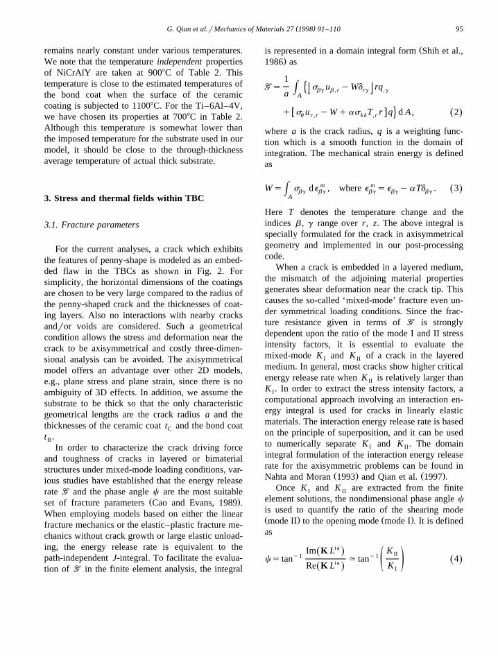
Žis represented in a domain integral form Shih et al.,.1986 as
1GGs s u yWd rq�H bg b ,r rg ,ga A
w xq s u yWqas T r q d A , 2Ž .4u r ,r k k ,r
where a is the crack radius, q is a weighting func-tion which is a smooth function in the domain ofintegration. The mechanical strain energy is definedas
Ws s de m , where e m se yaTd . 3Ž .H bg bg bg bg bgA
Here T denotes the temperature change and theindices b , g range over r, z. The above integral isspecially formulated for the crack in axisymmetricalgeometry and implemented in our post-processingcode.
When a crack is embedded in a layered medium,the mismatch of the adjoining material propertiesgenerates shear deformation near the crack tip. Thiscauses the so-called ‘mixed-mode’ fracture even un-der symmetrical loading conditions. Since the frac-ture resistance given in terms of GG is stronglydependent upon the ratio of the mode I and II stressintensity factors, it is essential to evaluate themixed-mode K and K of a crack in the layeredI II
medium. In general, most cracks show higher criticalenergy release rate when K is relatively larger thanII
K . In order to extract the stress intensity factors, aI
computational approach involving an interaction en-ergy integral is used for cracks in linearly elasticmaterials. The interaction energy release rate is basedon the principle of superposition, and it can be usedto numerically separate K and K . The domainI II
integral formulation of the interaction energy releaserate for the axisymmetric problems can be found in
Ž . Ž .Nahta and Moran 1993 and Qian et al. 1997 .Once K and K are extracted from the finiteI II
element solutions, the nondimensional phase angle c
is used to quantify the ratio of the shearing modeŽ . Ž .mode II to the opening mode mode I . It is definedas
Im K Lie KŽ . IIy1 y1cs tan , tan 4Ž .ie ž /KRe K LŽ . I
( )G. Qian et al.rMechanics of Materials 27 1998 91–11096
Here KsK q iK is called the complex stressI II
intensity factor and L is a characteristic length. For ahomogeneous crack, the above phase angle is inde-pendent of L, and it is equal to the right-hand
Ž .expression of Eq. 4 . When the crack is locatedwithin the elastic–plastic bond coat or along theinterface between the ceramic and bond coats, themixed-mode stress intensity factors can not be ex-tracted from the interaction energy integral. In thesecases the phase angle is determined from the stressesahead of the crack as,
sr zy1cs tan at us08 and rsL. 5Ž .ž /sz
Ž .As in the case of Eq. 4 , this phase angle dependson the characteristic length L. In order to establish aconsistent definition of c , we have evaluated c forseveral different elastic interface cracks with variousL. It was found that when Ls2 mm is chosen, c
Ž . Ž .determined from Eqs. 4 and 5 yield similar valuesfor these cracks. Based on this result, the phase angle
Ž . Ž .obtained either by Eq. 4 or Eq. 5 throughout thepaper is presented for Ls2 mm.
3.2. Steady-state heat transfer
3.2.1. Thermal gradient within TBCIn this study, a coupled steady-state temperature
and stress analysis is carried out. We have assumedthat the heatingrcooling process is sufficiently slowso that the transient heat transfer conditions are notimportant. The influences from radiation and the‘edge’ conduction are also ignored. In carrying outthe analysis, we have assumed that the top surface ofthe ceramic coating is exposed to a uniform environ-ment temperature. Within the ceramic and bond coats,the temperature decreases with depth until theboundary between the bond coat and the substrate isreached. Since the thermal conductivity of the sub-strate is much higher than that of TBCs, the tempera-ture field of the whole substrate is modeled to beconstant. The temperature drop through the coatingrepresents the insulation effect of the TBCs.
In a high temperature environment, the actualtemperature distribution within the coating can bedifficult to obtain due to its microstructure and un-steady boundary temperature. Instead of using a
complex model to estimate the precise temperatureŽdrop across the TBC i.e., the difference between
.surface and substrate temperatures , we have as-sumed it to vary linearly with the imposed surfacetemperature. Consequently, the prescribed tempera-tures at the surface and in the substrate are increased
Ž .linearly from room temperature 208C but at differ-ent rates. Initially, when there are no stresses in theTBCs, the temperature of whole model is set at208C. Then, the surface temperature T , i.e., thesurf
temperature on the top surface of the ceramic, isgradually increased to the maximum temperature of11008C while the substrate temperature T is in-sub
creased to 8508C. Thus, this thermal condition as-sumes the insulation or the temperature drop ofDTs2508C across the coating at the last thermalload step. Alternately, the temperature differencebetween the surface and the substrate is less than2508C during the loading. The temperature distribu-tion within the coatings during the loading is deter-mined from the finite element calculations. When nocrack exists in the TBCs, such a boundary conditionwill give a simple one-dimensional temperature vari-ation through the thickness. However, when the insu-lation effect across crack faces is considered, thetemperature field becomes more complex, especially
Ž .near the crack tip see Section 3.2.2 , and must bedetermined numerically. The thermal conductivitiesof the ceramic and the bond coats are shown inTable 1. Since the bond coat material is much morethermally conductive than that of sprayed YSZ, mostof the temperature drop within the TBC occurs acrossthe ceramic coating layer.
3.2.2. Insulation effect across crack facesIn the present analysis, another type of conduction
mechanism is considered. When a relatively largeŽ .crack compared to voids and microcracks opens up,
trapped air between the crack faces acts as a thermal‘shield’ against the otherwise normal heat flowthrough thickness because of its low thermal conduc-tivity. In fact, the thermal conductivity of dry air is
Žonly about 0.07 WrmP 8C at 9008C Touloukian,.1970 . This de facto thermal insulation by a crack
results in the large temperature jump across the crackfaces and promotes higher stress concentration. Such
Ž .an effect was studied by Hutchinson and Lu 1995
( )G. Qian et al.rMechanics of Materials 27 1998 91–110 97
who have shown that a discontinuous temperaturefield across the crack faces in a ceramic coating cansignificantly increase the energy release rate. Essen-tially, the temperature jump over the crack enhancesthe thermal expansion difference in the regions aboveand below the crack and generates a large mode II orshear loading near the crack tip. Subsequently, theinsulation across the crack faces may promote crackextension through increased crack driving force.
The temperature jump across the crack faces aremainly controlled by the heat conductance h overC
Žthe crack Eckert and Drake, 1972; Hutchinson and.Lu, 1995 . A large h indicates less thermal insula-C
tion and small temperature jump across the crackfaces. In our analysis, we have chosen the heatconductance h over opened crack faces to be aC
linear function of the crack opening displacement d
as,
h s1=104 Wrm2 P 8CC
y 5=108 Pd Wrm2 P 8C. 6Ž . Ž .
Here d varies along the crack faces depending uponthe local opening displacement. In general, h in-C
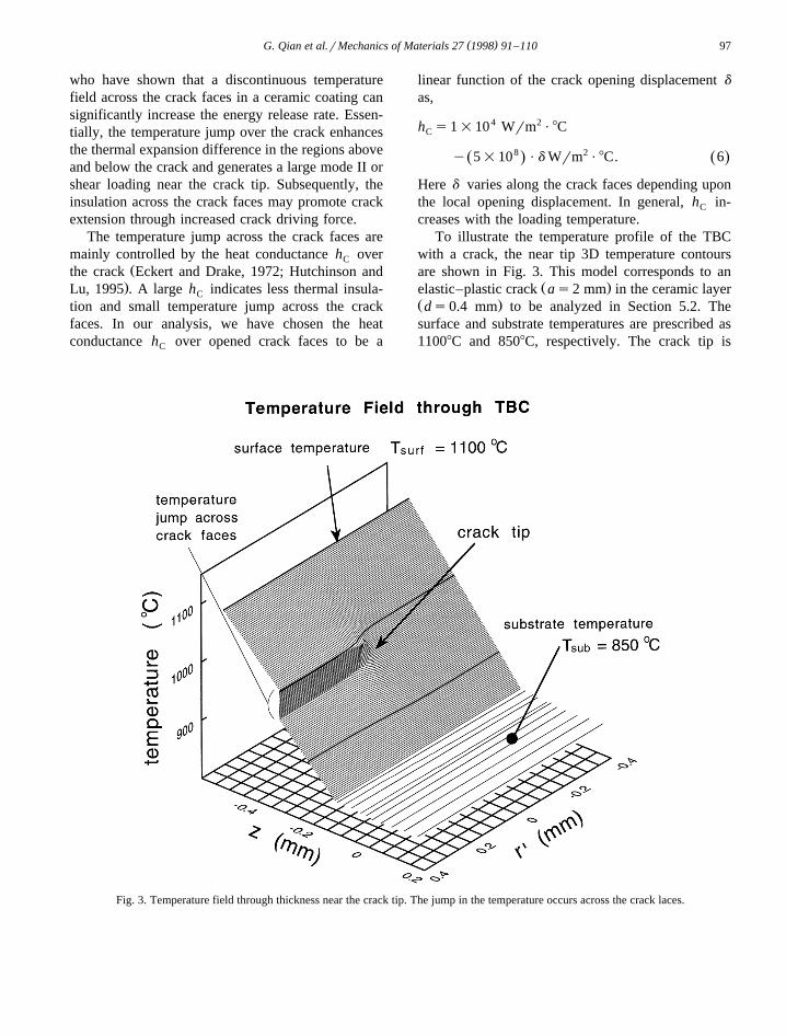
creases with the loading temperature.To illustrate the temperature profile of the TBC
with a crack, the near tip 3D temperature contoursare shown in Fig. 3. This model corresponds to an
Ž .elastic–plastic crack as2 mm in the ceramic layerŽ .ds0.4 mm to be analyzed in Section 5.2. Thesurface and substrate temperatures are prescribed as11008C and 8508C, respectively. The crack tip is
Fig. 3. Temperature field through thickness near the crack tip. The jump in the temperature occurs across the crack laces.
( )G. Qian et al.rMechanics of Materials 27 1998 91–11098
X Ž X .located at zs0.2 mm and r s0 note r srya .It is clear that a sharp temperature jump across thecrack faces exists and a complex temperature fieldaround the crack tip can be observed. At large rX
which is sufficiently ahead of the crack tip, thetemperature variation is nearly linear with z. More-over, most of the temperature drop occurs in theceramic layer and a very small insulation effect isobserved for the bond coat.
3.3. Residual stresses
Residual stresses are believed to affect the TBCintegrity in high temperature applications. BrindleyŽ .1995 conducted some experiments showing that thethermal fatigue lifetime of some TBCs is directlyrelated to the magnitude of the residual stresses.Many different mechanisms related to the residual
Žstresses in TBCs have been discussed Elsing et al.,.1990; Takeuchi et al., 1990 . Some of these mecha-
nisms and their aftermath are addressed separatelyhere.
The first mechanism concerns phase transforma-tions. For example, unstabilized pure zirconia whichcools down from an impinging temperature wellabove 20008C to room temperature will transformfrom tetragonal phase to monoclinic phase. Thisphase transformation will bring about an internal
Žvolume increase of 8% inside the zirconia Bever,.1986 and vice versa. Consequently, very large resid-
ual stresses will appear as a result. But in the realapplications, pure zirconia is rarely used. Instead, the
Ž .partially stabilized zirconia PSZ , for example, ZrO2
q6;8 wt% Y O where yttria is added as stabi-2 3Ž .lizer, is used Herman and Shankar, 1987 . The
added stabilizer can minimize the phase transforma-tion effect and keep the highly disruptive volumechange at bay. Therefore, residual stresses due to thephase transformation are neglected in this paper.
The second mechanism is the solidification pro-cess of the molten coating powder on top of itssubstrate after exiting from the nozzle of the spray-ing gun. The temperature of the molten powder is
Žusually from T s25008C to 30008C Harding etexit.al., 1995 . Since the cooling rate of the spraying
6 Žparticle is very high, typically about 10 8Crs Mc-.Pherson, 1989 , it takes only about 1 ms for the very
Ž .thin splat a few micrometers in thickness to con-
tract and condense on the underlying material whichis extremely thick relative to the splat. Therefore, theunderlying substrate can be regarded as rigid com-pared to the impinging and condensing thin layer ofsplat. Consequently, the ensuing residual stresses inthe condensing splats due to the solidification aretensile stresses. The magnitude of the tensile residualstress from the above scenario can be estimated from
Ž .ssE a T yT , where E and a are thec c exit dep c c
modulus and CTE of the splat and T is the deposi-depŽ .tion temperature 200;4008C . According to such a
formula, the stress can reach as high as 200 MPa.This estimation is purely theoretical. In practice,residual stresses due to the solidification are notsignificant since other ongoing processes reduce thetensile residual stresses. First, the tensile stressesinside coatings will inevitably induce microcrackingand other structural degradation which in turn canreduce the tension inside the coatings. This processis similar to stress relaxation. On the other hand, thecontinual deposition of material on top of the previ-ously deposited laminae of coating will induce com-pressive stresses underneath the current layer of de-position. As the thickness of coating builds up, muchof the tensile residual stress induced during solidifi-cation might be compensated by the compressivestresses. All of these facts imply that the actualresidual stress due to primary cooling is much smallerthan that predicted theoretically. Some authors haveargued that the solidification is quite insignificant interms of generating the residual stresses in coatingsŽ .Takeuchi et al., 1990 .
The third mechanism is secondary cooling wherethe coating system and substrate cool from the depo-sition temperature to room temperature. The mis-match of the CTEs of different materials is the majorreason that large residual stresses ensue after cool-ing. This secondary cooling process is generallyregarded as the prime mechanism related to theresidual stresses which affect the overall integrity ofthe coatings.
4. Linear elastic model
4.1. Computational procedure
Initially, a linear elastic model of the entire TBCis considered. The reason for carrying out the linear
( )G. Qian et al.rMechanics of Materials 27 1998 91–110 99
elastic analysis is that the results of this modelenable us to distinguish the nonlinear effect of theelastic–plastic models and isolate the other importantphysical effects. The elastic–plastic analysis is pre-sented in Section 5. Here, all materials including theNiCrAlY and Ti–6Al–4V are assumed to be linearlyelastic and only the elastic properties listed in Table1 are used. The thicknesses of the ceramic coatingand bond coat are chosen as t s400 mm andC
t s130 mm, respectively, and represent typicalB
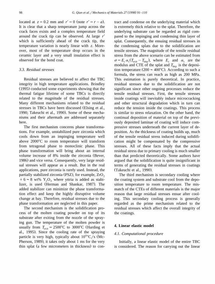
thicknesses of TBCs. The origin of the cylindricalŽ .coordinates r and z is shown in Fig. 2 b . Two
geometrical locations are considered for an embed-ded penny-shaped crack. One is a homogeneouscrack located somewhere within the ceramic coatingand the other is an interface crack lying between theceramic and bond coats as shown in Fig. 4. Here thedepth location is measured from the surface of theceramic coating and denoted as d. We did notconsider cracks at other geometrically significant
Ž .locations e.g., within the bond coat because ourprevious analysis has shown that the fracture tough-
Žness in such locations to be much higher Qian et al.,.1997 . The diameter of the penny-shaped crack is
assumed to range from 2 as0.2 to 8 mm.In our finite element model, the thickness and
radius of the substrate are chosen to be 20 times thethickness of TBCs in order to represent a thick andlarge substrate. Since a large number of differentmodels must be analyzed, a mesh generator code wasdeveloped using 4-node bilinear isoparametric ax-isymmetric elements. In order to determine the tem-
Fig. 4. Two locations of embedded cracks shown in the cross-sec-tions of axisymmetrical models. The location of the crack d is
Ž .measured from the surface of the ceramic coating. a Homoge-Ž .neous crack within the ceramic coating. b Interface crack be-
tween the ceramic and bond coatings.
perature field as well as the deformation field nearthe crack tip accurately, specially refined elementsare placed in the crack tip region. Such a meshdesign is also required for accurate calculations ofcrack tip parameters. Additionally, small elementsare used near the boundaries of different layers tocapture large strain changes caused by the materialmismatch. An axisymmetry condition is prescribedalong rs0 while the roller type boundary conditionis placed along the bottom of the substrate. Noexternal load is applied in this analysis. About 2000elements are used in a typical model. To model thecrack insulation effect discussed in Section 3.2.2,special interface elements are placed between thecrack surfaces. Each interface element is connectedto a pair of nodes on the upper and lower faces ofthe crack. This element permits one-dimensional heatconduction across the ‘gap’ of an opened crack asdetermined by the opening displacement between the
Ž .two nodes based on Eq. 6 . Furthermore, theseelements prevent the crack faces from overlappingeach other when the crack tends to close. Since theheat conduction is a function of the crack opening,the use of these elements make the analysis nonlin-ear, even for the linear elastic model. Typically, 2 to3 iterations are carried out to achieve an equilibriumcondition at each increment.
4.2. Computational results
Three physical factors can contribute to the growthŽ .of internal cracks in the coatings. They are i the
Ž .material mismatch primarily the CTE differenceŽ .among different layers, ii the thermal gradientsŽ .through the coatings, and iii the thermal insulation
across the crack faces. Here the resulting energyrelease rate is calculated for different prescribed
Ž .temperatures using Eq. 2 . In addition, the phaseŽ .angle according to Eq. 4 is determined at every
increment from calculated K and K .I II
In the finite element analysis, the boundary tem-peratures, both T and T are initially set at thesurf sub
Ž .room temperature 208C and increased linearly withtime increments but at different rates. The calcula-tions are carried out until T s11008C and T ssurf sub
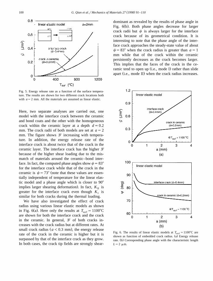
8508C are reached. In Fig. 5, the energy release rateis shown as a function of the surface temperature.
( )G. Qian et al.rMechanics of Materials 27 1998 91–110100
Fig. 5. Energy release rate as a function of the surface tempera-ture. The results are shown for two different crack locations bothwith as2 mm. All the materials are assumed as linear elastic.
Here, two separate analyses are carried out, onemodel with the interface crack between the ceramicand bond coats and the other with the homogeneouscrack within the ceramic layer at a depth ds0.2mm. The crack radii of both models are set at as2mm. The figure shows GG increasing with tempera-ture. In addition, the energy release rate of theinterface crack is about twice that of the crack in theceramic layer. The interface crack has the higher GG
because of the higher shear loading due to the mis-match of materials around the ceramic–bond inter-face. In fact, the computed phase angles show cs838
for the interface crack while that of the crack in theŽceramic is cs738 note that these values are essen-
tially independent of temperature for the linear elas-tic model and a phase angle which is closer to 908
.implies larger shearing deformation . In fact, K isII
greater for the interface crack even though K isI
similar for both cracks during the thermal loading.We have also investigated the effect of crack
radius using various linear elastic models as shownŽ .in Fig. 6 a . Here only the results at T s11008Csurf
are shown for both the interface crack and the crackin the ceramic. In general, GG of both cracks in-creases with the crack radius but at different rates. At
Ž .small crack radius a-0.3 mm , the energy releaserate of the crack in the ceramic is higher but it issurpassed by that of the interface crack as they grow.In both cases, the crack tip fields are strongly shear-
dominant as revealed by the results of phase angle inŽ .Fig. 6 b . Both phase angles decrease for larger
crack radii but c is always larger for the interfacecrack because of its geometrical condition. It isinteresting to note that the phase angle of the inter-face crack approaches the steady-state value of aboutcs838 when the crack radius is greater than as1mm while that of the crack within the ceramicpersistently decreases as the crack becomes larger.This implies that the faces of the crack in the ce-
Ž .ramic tend to open up i.e., mode I rather than slideŽ .apart i.e., mode II when the crack radius increases.
Fig. 6. The results of linear elastic models at T s11008C aresurfŽ .shown as function of embedded crack radius. a Energy release
Ž .rate. b Corresponding phase angle with the characteristic lengthLs2 mm.
( )G. Qian et al.rMechanics of Materials 27 1998 91–110 101
5. Elastic–plastic model
5.1. Computational procedure
Similar thermal boundary conditions and finiteelement meshes as described in the linear elasticmodel are employed in elastic–plastic models. Ini-tially the results of temperature-independent materialmodels are presented and then the temperature-de-pendent model is used. In this way, the effect of theplastic or nonlinear deformation can be clearly iden-tified by comparison with the elastic results. Theproperties of the temperature-independent model arelisted in Table 1 while those of the temperature-de-pendent model are listed in Table 2. We note that thetemperature-dependent properties are obtained froma collection of limited sources and some data may beapproximate. In both cases, the ceramic coating isassumed to remain linear elastic throughout the ther-mal loading. To ensure the accuracy of the results forthe elastic–plastic model, smaller temperature incre-ments are taken. On average, 30 increments are usedto raise the surface temperature to 11008C.
5.2. Results of temperature-independent elastic–plas-tic model
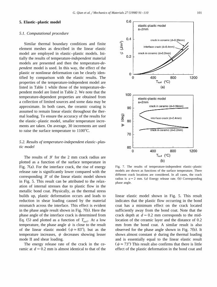
The results of GG for the 2 mm crack radius areplotted as a function of the surface temperature in
Ž .Fig. 7 a . For the interface crack, the rise of energyrelease rate is significantly lower compared with thecorresponding GG of the linear elastic model shownin Fig. 5. This result can be attributed to the relax-ation of internal stresses due to plastic flow in themetallic bond coat. Physically, as the thermal stressbuilds up, plastic deformation occurs and leads toreduction in shear loading caused by the materialmismatch across the interface. This effect is evident
Ž .in the phase angle result shown in Fig. 7 b . Here thephase angle of the interface crack is determined from
Ž .Eq. 5 and plotted as a function of T . At a lowsurf
temperature, the phase angle c is close to the resultŽ .of the linear elastic model c,838 , but as the
temperature increases, c decreases showing lessermode II and shear loading.
The energy release rate of the crack in the ce-ramic at ds0.2 mm is almost identical to that of the
Fig. 7. The results of temperature-independent elastic–plasticmodels are shown as functions of the surface temperature. Theredifferent crack locations are considered. In all cases, the crack
Ž . Ž .radius is as2 mm. a Energy release rate. b Correspondingphase angle.
linear elastic model shown in Fig. 5. This resultindicates that the plastic flow occurring in the bondcoat has a minimum effect on the crack locatedsufficiently away from the bond coat. Note that thecrack depth at ds0.2 mm corresponds to the mid-location of the ceramic layer and the distance of 0.2mm from the bond coat. A similar result is also
Ž .observed for the phase angle shown in Fig. 7 b . Itshows almost constant c during the thermal loadingand is essentially equal to the linear elastic resultŽ .c,738 This result also confirms that there is littleeffect of the plastic deformation in the bond coat and
( )G. Qian et al.rMechanics of Materials 27 1998 91–110102
the substrate when a crack is located well within theceramic coating.
In order to investigate any influence of plasticflow on a crack in the ceramic layer, we have studiedanother crack located very close to the bond coat. Inthis model, the crack in the ceramic is placed atds0.39 mm from the surface, i.e., at a distance ofonly 10 mm away from the ceramic–bond interface.The energy release rate of this model shows a higherrate of increase with T than that of the crack atsurf
ds2 mm. These results illustrate the influence ofthe bond coat plasticity on the near-interface crack.In fact, the energy release rate at T s11008C ofsurf
this homogeneous crack is higher than that of theinterface crack. Interestingly, the phase angle shown
Ž .in Fig. 7 b suggests increasing shear loading as thetemperature is increased. Based on these results andthe fact that the fracture toughness of the ceramic–bond interface is higher than that of the ceramic
Žcoating Oliveira and Bower, 1996; Qian et al.,.1997 , a homogeneous crack near the interface may
be more susceptible to propagation. This issue willbe further discussed in Section 5.3.
5.3. Effect of residual stresses
The residual stresses in a bonded ceramicrmetalhave been studied both analytically and experimen-
Ž .tally Hsueh and Evans, 1985; Koguchi et al., 1994 .As discussed earlier, thermal residual stresses candevelop during the fabrication process of TBCs.Since plasma sprayed coatings are made by buildingup many molten splats, predicting accurate residualstresses is extremely difficult. In fact, any change in
Žthe manufacturing process e.g., flow behavior of.splats can influence the residual stress state within
coatings. To circumvent the complexity of modelingthe precise cooling down process, we considered acondition which yields extreme residual stresses. Itwas discussed in Section 3.3 that secondary coolingcan be the major factor for large residual stresses inthe TBCs. Here, to model the secondary cooling, it isassumed that the whole TBC system is initially at auniform temperature of 7008C and slowly cooled
Ž .down to room temperature 208C . This process re-sults in residual stresses within TBCs due to the CTEmismatch. In such a procedure, the initial tempera-ture also corresponds to the so-called ‘zero-stress’
temperature. Alternatively, one can choose anotherzero-stress temperature to control the amount ofresidual stress that results at room temperature. Al-though the choice of 7008C is made arbitrarily, webelieve it represents an upper bound of zero-stresstemperature of actual TBCs. Thus, cooling downfrom this temperature should generate close to themaximum residual stress for any TBC. Accordingly,if the actual zero-stress temperature is less than7008C, then the effect of residual stresses on thefracture parameters should fall between the results ofthis 7008C model and the model without residualstresses presented in the previous section. The zero-stress temperature of the previous section can be
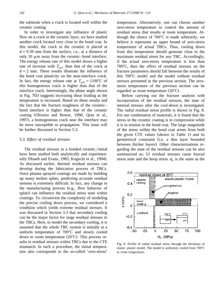
Ž .regarded as room temperature 208C .Before carrying out the fracture analysis with
incorporation of the residual stresses, the state ofinternal stresses after the cool-down is investigated.The radial residual stress profile is shown in Fig. 8.For our combination of materials, it is found that thestress in the ceramic coating is in compression whileit is in tension in the bond coat. The large magnitudeof the stress within the bond coat arises from both
Ž .the given CTE values shown in Table 1 and itsŽgeometrical constraint i.e, a thin layer bounded
.between thicker layers . Other characterizations re-garding the state of the residual stresses can be also
Ž .summarized as; i residual stresses cause biaxialstress state and the hoop stress s is the same as theu
Fig. 8. Profile of radial residual stress through the thickness ofelastic–plastic model. The model is uniformly cooled from 7008Cto room temperature.
( )G. Qian et al.rMechanics of Materials 27 1998 91–110 103
radial stress while the other components of stress areŽ .very small, ii the residual stress is constant in eachŽ .layer, and iii the compressive stress in the ceramic
would discourage crack advance along the verticaldirection. We also note that the magnitudes of theresidual stresses are very sensitive to the relativevalues of CTEs.
Although not shown here, the residual stresses ofthe linear elastic model are also computed. Theresults show that the radial residual stress reachesclose to 480 MPa in the bond coat which is aboutfive times as high as that in the elastic–plasticmodel. It is clear that yielding in the bond coatreduces the magnitude of residual stresses dramati-cally. In some earlier papers, the residual stresses inthe TBCs were predicted from linear elastic modelsand these might have exaggerated the magnitudes ofthe residual stresses. The residual stresses can playan important role in the performance and durability
Ž .of TBCs Brindley, 1995 but its effect on the me-chanical integrity is yet to be clarified. In order toenhance the quality of TBCs, it is crucial to searchfor the answer in both qualitative and a quantitativemanners. We approached this problem from the per-spective of fracture mechanics and results from theelastic–plastic model are presented next.
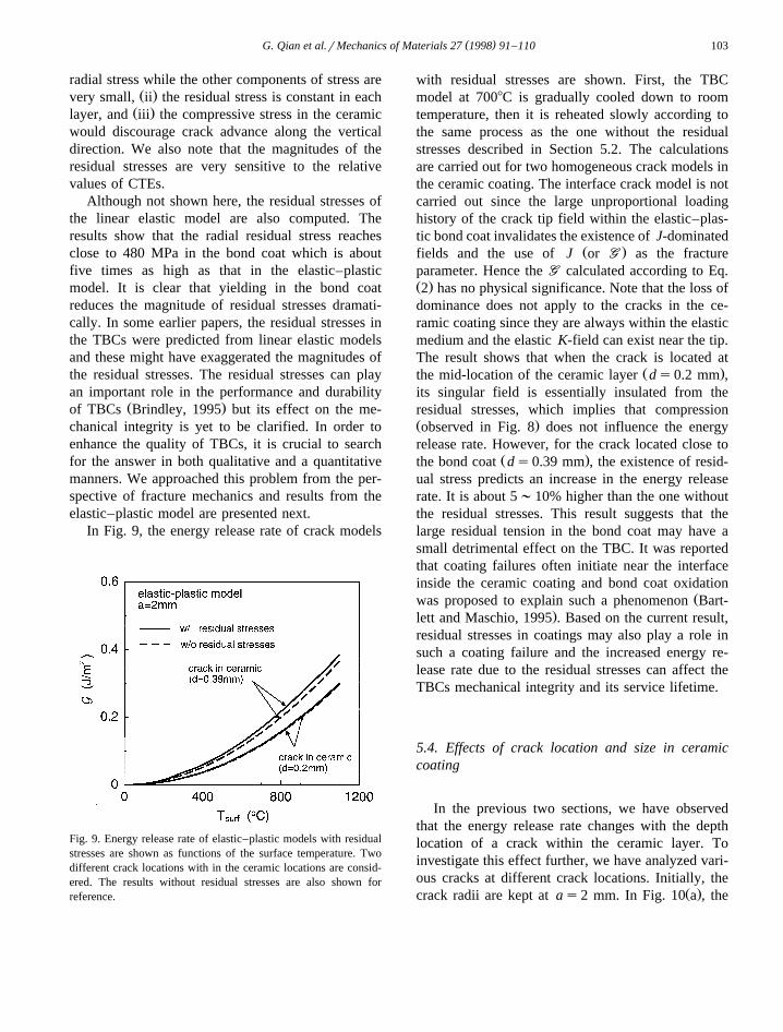
In Fig. 9, the energy release rate of crack models
Fig. 9. Energy release rate of elastic–plastic models with residualstresses are shown as functions of the surface temperature. Twodifferent crack locations with in the ceramic locations are consid-ered. The results without residual stresses are also shown forreference.
with residual stresses are shown. First, the TBCmodel at 7008C is gradually cooled down to roomtemperature, then it is reheated slowly according tothe same process as the one without the residualstresses described in Section 5.2. The calculationsare carried out for two homogeneous crack models inthe ceramic coating. The interface crack model is notcarried out since the large unproportional loadinghistory of the crack tip field within the elastic–plas-tic bond coat invalidates the existence of J-dominated
Ž .fields and the use of J or GG as the fractureparameter. Hence the GG calculated according to Eq.Ž .2 has no physical significance. Note that the loss ofdominance does not apply to the cracks in the ce-ramic coating since they are always within the elasticmedium and the elastic K-field can exist near the tip.The result shows that when the crack is located at
Ž .the mid-location of the ceramic layer ds0.2 mm ,its singular field is essentially insulated from theresidual stresses, which implies that compressionŽ .observed in Fig. 8 does not influence the energyrelease rate. However, for the crack located close to
Ž .the bond coat ds0.39 mm , the existence of resid-ual stress predicts an increase in the energy releaserate. It is about 5;10% higher than the one withoutthe residual stresses. This result suggests that thelarge residual tension in the bond coat may have asmall detrimental effect on the TBC. It was reportedthat coating failures often initiate near the interfaceinside the ceramic coating and bond coat oxidation
Žwas proposed to explain such a phenomenon Bart-.lett and Maschio, 1995 . Based on the current result,
residual stresses in coatings may also play a role insuch a coating failure and the increased energy re-lease rate due to the residual stresses can affect theTBCs mechanical integrity and its service lifetime.
5.4. Effects of crack location and size in ceramiccoating
In the previous two sections, we have observedthat the energy release rate changes with the depthlocation of a crack within the ceramic layer. Toinvestigate this effect further, we have analyzed vari-ous cracks at different crack locations. Initially, the
Ž .crack radii are kept at as2 mm. In Fig. 10 a , the
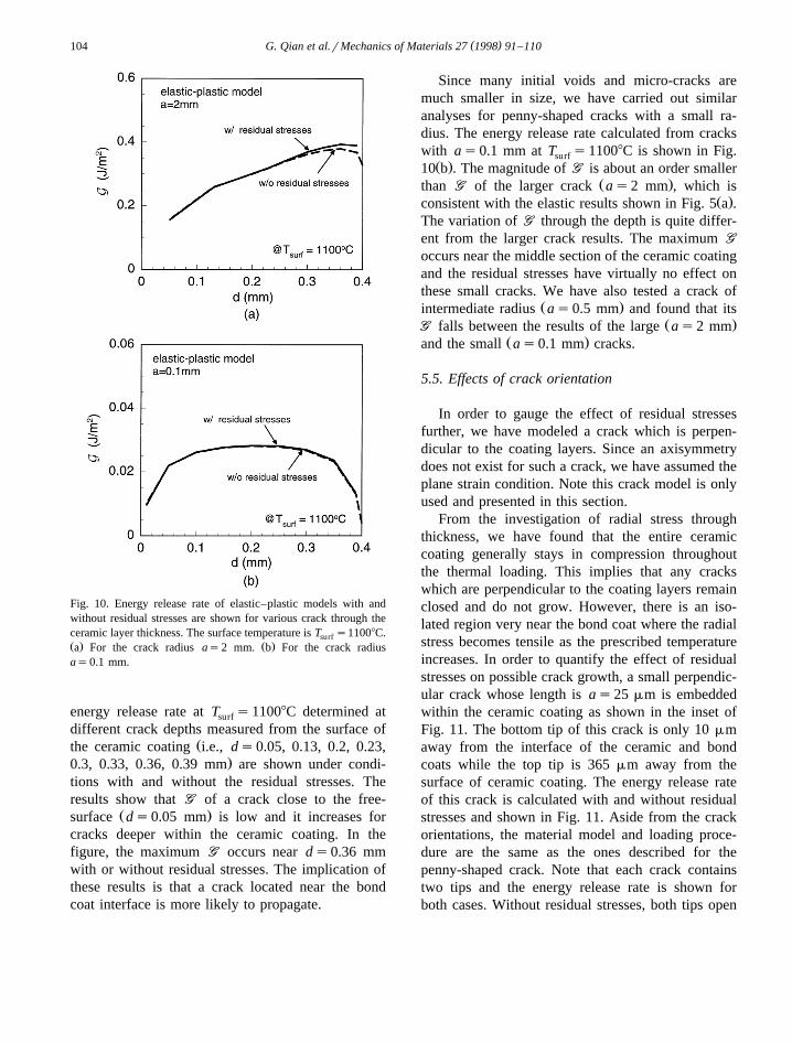
( )G. Qian et al.rMechanics of Materials 27 1998 91–110104
Fig. 10. Energy release rate of elastic–plastic models with andwithout residual stresses are shown for various crack through theceramic layer thickness. The surface temperature is T s11008C.surfŽ . Ž .a For the crack radius as2 mm. b For the crack radiusas0.1 mm.
energy release rate at T s11008C determined atsurf
different crack depths measured from the surface ofŽthe ceramic coating i.e., ds0.05, 0.13, 0.2, 0.23,
.0.3, 0.33, 0.36, 0.39 mm are shown under condi-tions with and without the residual stresses. Theresults show that GG of a crack close to the free-
Ž .surface ds0.05 mm is low and it increases forcracks deeper within the ceramic coating. In thefigure, the maximum GG occurs near ds0.36 mmwith or without residual stresses. The implication ofthese results is that a crack located near the bondcoat interface is more likely to propagate.
Since many initial voids and micro-cracks aremuch smaller in size, we have carried out similaranalyses for penny-shaped cracks with a small ra-dius. The energy release rate calculated from crackswith as0.1 mm at T s11008C is shown in Fig.surfŽ .10 b . The magnitude of GG is about an order smaller
Ž .than GG of the larger crack as2 mm , which isŽ .consistent with the elastic results shown in Fig. 5 a .
The variation of GG through the depth is quite differ-ent from the larger crack results. The maximum GG
occurs near the middle section of the ceramic coatingand the residual stresses have virtually no effect onthese small cracks. We have also tested a crack of
Ž .intermediate radius as0.5 mm and found that itsŽ .GG falls between the results of the large as2 mm
Ž .and the small as0.1 mm cracks.
5.5. Effects of crack orientation
In order to gauge the effect of residual stressesfurther, we have modeled a crack which is perpen-dicular to the coating layers. Since an axisymmetrydoes not exist for such a crack, we have assumed theplane strain condition. Note this crack model is onlyused and presented in this section.
From the investigation of radial stress throughthickness, we have found that the entire ceramiccoating generally stays in compression throughoutthe thermal loading. This implies that any crackswhich are perpendicular to the coating layers remainclosed and do not grow. However, there is an iso-lated region very near the bond coat where the radialstress becomes tensile as the prescribed temperatureincreases. In order to quantify the effect of residualstresses on possible crack growth, a small perpendic-ular crack whose length is as25 mm is embeddedwithin the ceramic coating as shown in the inset ofFig. 11. The bottom tip of this crack is only 10 mmaway from the interface of the ceramic and bondcoats while the top tip is 365 mm away from thesurface of ceramic coating. The energy release rateof this crack is calculated with and without residualstresses and shown in Fig. 11. Aside from the crackorientations, the material model and loading proce-dure are the same as the ones described for thepenny-shaped crack. Note that each crack containstwo tips and the energy release rate is shown forboth cases. Without residual stresses, both tips open
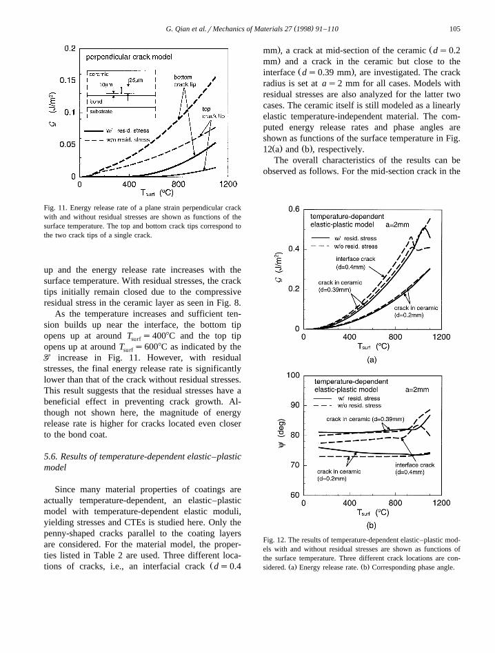
( )G. Qian et al.rMechanics of Materials 27 1998 91–110 105
Fig. 11. Energy release rate of a plane strain perpendicular crackwith and without residual stresses are shown as functions of thesurface temperature. The top and bottom crack tips correspond tothe two crack tips of a single crack.
up and the energy release rate increases with thesurface temperature. With residual stresses, the cracktips initially remain closed due to the compressiveresidual stress in the ceramic layer as seen in Fig. 8.
As the temperature increases and sufficient ten-sion builds up near the interface, the bottom tipopens up at around T s4008C and the top tipsurf
opens up at around T s6008C as indicated by thesurf
GG increase in Fig. 11. However, with residualstresses, the final energy release rate is significantlylower than that of the crack without residual stresses.This result suggests that the residual stresses have abeneficial effect in preventing crack growth. Al-though not shown here, the magnitude of energyrelease rate is higher for cracks located even closerto the bond coat.
5.6. Results of temperature-dependent elastic–plasticmodel
Since many material properties of coatings areactually temperature-dependent, an elastic–plasticmodel with temperature-dependent elastic moduli,yielding stresses and CTEs is studied here. Only thepenny-shaped cracks parallel to the coating layersare considered. For the material model, the proper-ties listed in Table 2 are used. Three different loca-
Žtions of cracks, i.e., an interfacial crack ds0.4
. Žmm , a crack at mid-section of the ceramic ds0.2
.mm and a crack in the ceramic but close to theŽ .interface ds0.39 mm , are investigated. The crack
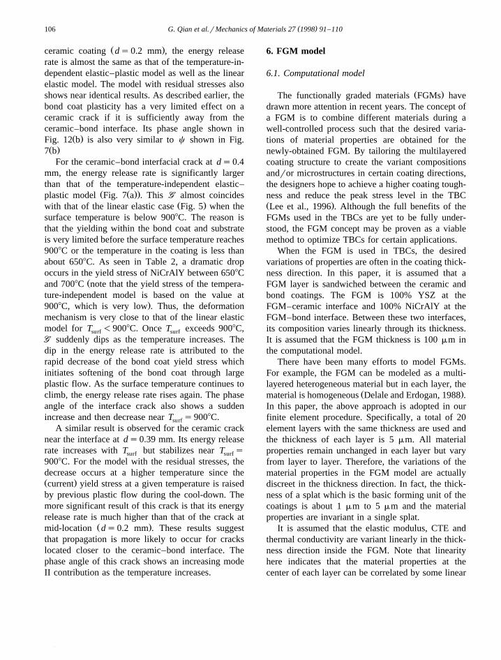
radius is set at as2 mm for all cases. Models withresidual stresses are also analyzed for the latter twocases. The ceramic itself is still modeled as a linearlyelastic temperature-independent material. The com-puted energy release rates and phase angles areshown as functions of the surface temperature in Fig.Ž . Ž .12 a and b , respectively.The overall characteristics of the results can be
observed as follows. For the mid-section crack in the
Fig. 12. The results of temperature-dependent elastic–plastic mod-els with and without residual stresses are shown as functions ofthe surface temperature. Three different crack locations are con-
Ž . Ž .sidered. a Energy release rate. b Corresponding phase angle.
( )G. Qian et al.rMechanics of Materials 27 1998 91–110106
Ž .ceramic coating ds0.2 mm , the energy releaserate is almost the same as that of the temperature-in-dependent elastic–plastic model as well as the linearelastic model. The model with residual stresses alsoshows near identical results. As described earlier, thebond coat plasticity has a very limited effect on aceramic crack if it is sufficiently away from theceramic–bond interface. Its phase angle shown in
Ž .Fig. 12 b is also very similar to c shown in Fig.Ž .7 b
For the ceramic–bond interfacial crack at ds0.4mm, the energy release rate is significantly largerthan that of the temperature-independent elastic–
Ž Ž ..plastic model Fig. 7 a . This GG almost coincidesŽ .with that of the linear elastic case Fig. 5 when the
surface temperature is below 9008C. The reason isthat the yielding within the bond coat and substrateis very limited before the surface temperature reaches9008C or the temperature in the coating is less thanabout 6508C. As seen in Table 2, a dramatic dropoccurs in the yield stress of NiCrAlY between 6508C
Žand 7008C note that the yield stress of the tempera-ture-independent model is based on the value at
.9008C, which is very low . Thus, the deformationmechanism is very close to that of the linear elasticmodel for T -9008C. Once T exceeds 9008C,surf surf
GG suddenly dips as the temperature increases. Thedip in the energy release rate is attributed to therapid decrease of the bond coat yield stress whichinitiates softening of the bond coat through largeplastic flow. As the surface temperature continues toclimb, the energy release rate rises again. The phaseangle of the interface crack also shows a suddenincrease and then decrease near T s9008C.surf
A similar result is observed for the ceramic cracknear the interface at ds0.39 mm. Its energy releaserate increases with T but stabilizes near T ssurf surf
9008C. For the model with the residual stresses, thedecrease occurs at a higher temperature since theŽ .current yield stress at a given temperature is raisedby previous plastic flow during the cool-down. Themore significant result of this crack is that its energyrelease rate is much higher than that of the crack at
Ž .mid-location ds0.2 mm . These results suggestthat propagation is more likely to occur for crackslocated closer to the ceramic–bond interface. Thephase angle of this crack shows an increasing modeII contribution as the temperature increases.
6. FGM model
6.1. Computational model
Ž .The functionally graded materials FGMs havedrawn more attention in recent years. The concept ofa FGM is to combine different materials during awell-controlled process such that the desired varia-tions of material properties are obtained for thenewly-obtained FGM. By tailoring the multilayeredcoating structure to create the variant compositionsandror microstructures in certain coating directions,the designers hope to achieve a higher coating tough-ness and reduce the peak stress level in the TBCŽ .Lee et al., 1996 . Although the full benefits of theFGMs used in the TBCs are yet to be fully under-stood, the FGM concept may be proven as a viablemethod to optimize TBCs for certain applications.
When the FGM is used in TBCs, the desiredvariations of properties are often in the coating thick-ness direction. In this paper, it is assumed that aFGM layer is sandwiched between the ceramic andbond coatings. The FGM is 100% YSZ at theFGM–ceramic interface and 100% NiCrAlY at theFGM–bond interface. Between these two interfaces,its composition varies linearly through its thickness.It is assumed that the FGM thickness is 100 mm inthe computational model.
There have been many efforts to model FGMs.For example, the FGM can be modeled as a multi-layered heterogeneous material but in each layer, the
Ž .material is homogeneous Delale and Erdogan, 1988 .In this paper, the above approach is adopted in ourfinite element procedure. Specifically, a total of 20element layers with the same thickness are used andthe thickness of each layer is 5 mm. All materialproperties remain unchanged in each layer but varyfrom layer to layer. Therefore, the variations of thematerial properties in the FGM model are actuallydiscreet in the thickness direction. In fact, the thick-ness of a splat which is the basic forming unit of thecoatings is about 1 mm to 5 mm and the materialproperties are invariant in a single splat.
It is assumed that the elastic modulus, CTE andthermal conductivity are variant linearly in the thick-ness direction inside the FGM. Note that linearityhere indicates that the material properties at thecenter of each layer can be correlated by some linear
( )G. Qian et al.rMechanics of Materials 27 1998 91–110 107
curves since the actual variations discussed aboveare discreet due to the finite thickness of each indi-vidual layer. If two materials sandwiching the FGMare linear elastic materials, the above assumption inthe computational model will suffice. In the elastic–plastic model, the elastic–plastic bond coat materialis mixed with the elastic ceramic to produce theFGM. Now the question arises on how to model theFGM yielding since the ceramic which forms part ofthe FGM does not yield. There have been manyefforts to use a matrix-inclusion model based on theMori–Tanaka method to model the ceramicrmetal
Žmixture and, hence, the FGM Weissenbek et al.,.1997 . In this paper, a simpler mixture rule of FGM
yielding model is proposed for the yielding of theFGM composed of a variant ceramicrmetal mixture.
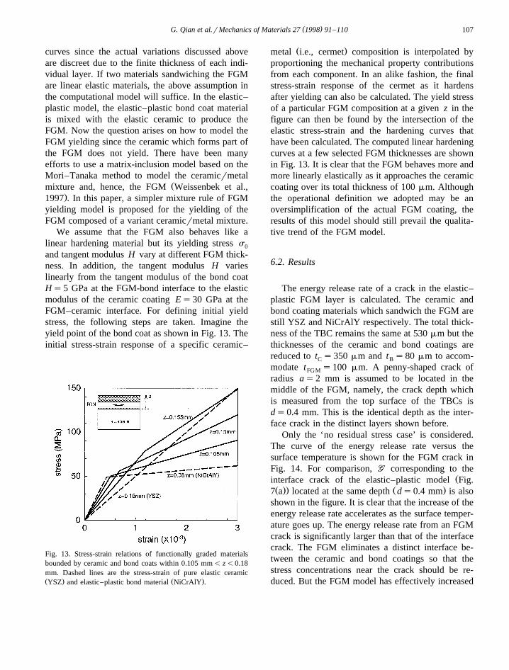
We assume that the FGM also behaves like alinear hardening material but its yielding stress s0
and tangent modulus H vary at different FGM thick-ness. In addition, the tangent modulus H varieslinearly from the tangent modulus of the bond coatHs5 GPa at the FGM-bond interface to the elasticmodulus of the ceramic coating Es30 GPa at theFGM–ceramic interface. For defining initial yieldstress, the following steps are taken. Imagine theyield point of the bond coat as shown in Fig. 13. Theinitial stress-strain response of a specific ceramic–
Fig. 13. Stress-strain relations of functionally graded materialsbounded by ceramic and bond coats within 0.105 mm- z-0.18mm. Dashed lines are the stress-strain of pure elastic ceramicŽ . Ž .YSZ and elastic–plastic bond material NiCrAlY .
Ž .metal i.e., cermet composition is interpolated byproportioning the mechanical property contributionsfrom each component. In an alike fashion, the finalstress-strain response of the cermet as it hardensafter yielding can also be calculated. The yield stressof a particular FGM composition at a given z in thefigure can then be found by the intersection of theelastic stress-strain and the hardening curves thathave been calculated. The computed linear hardeningcurves at a few selected FGM thicknesses are shownin Fig. 13. It is clear that the FGM behaves more andmore linearly elastically as it approaches the ceramiccoating over its total thickness of 100 mm. Althoughthe operational definition we adopted may be anoversimplification of the actual FGM coating, theresults of this model should still prevail the qualita-tive trend of the FGM model.
6.2. Results
The energy release rate of a crack in the elastic–plastic FGM layer is calculated. The ceramic andbond coating materials which sandwich the FGM arestill YSZ and NiCrAlY respectively. The total thick-ness of the TBC remains the same at 530 mm but thethicknesses of the ceramic and bond coatings arereduced to t s350 mm and t s80 mm to accom-C B
modate t s100 mm. A penny-shaped crack ofFGM
radius as2 mm is assumed to be located in themiddle of the FGM, namely, the crack depth whichis measured from the top surface of the TBCs isds0.4 mm. This is the identical depth as the inter-face crack in the distinct layers shown before.
Only the ‘no residual stress case’ is considered.The curve of the energy release rate versus thesurface temperature is shown for the FGM crack inFig. 14. For comparison, GG corresponding to the
Žinterface crack of the elastic–plastic model Fig.Ž .. Ž .7 a located at the same depth ds0.4 mm is also
shown in the figure. It is clear that the increase of theenergy release rate accelerates as the surface temper-ature goes up. The energy release rate from an FGMcrack is significantly larger than that of the interfacecrack. The FGM eliminates a distinct interface be-tween the ceramic and bond coatings so that thestress concentrations near the crack should be re-duced. But the FGM model has effectively increased
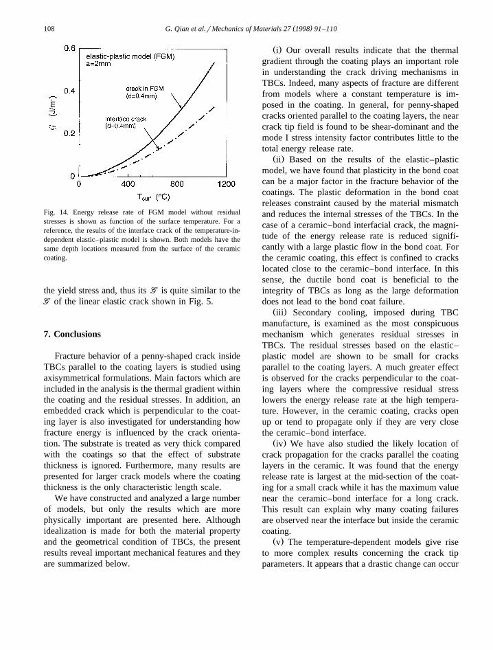
( )G. Qian et al.rMechanics of Materials 27 1998 91–110108
Fig. 14. Energy release rate of FGM model without residualstresses is shown as function of the surface temperature. For areference, the results of the interface crack of the temperature-in-dependent elastic–plastic model is shown. Both models have thesame depth locations measured from the surface of the ceramiccoating.
the yield stress and, thus its GG is quite similar to theGG of the linear elastic crack shown in Fig. 5.
7. Conclusions
Fracture behavior of a penny-shaped crack insideTBCs parallel to the coating layers is studied usingaxisymmetrical formulations. Main factors which areincluded in the analysis is the thermal gradient withinthe coating and the residual stresses. In addition, anembedded crack which is perpendicular to the coat-ing layer is also investigated for understanding howfracture energy is influenced by the crack orienta-tion. The substrate is treated as very thick comparedwith the coatings so that the effect of substratethickness is ignored. Furthermore, many results arepresented for larger crack models where the coatingthickness is the only characteristic length scale.
We have constructed and analyzed a large numberof models, but only the results which are morephysically important are presented here. Althoughidealization is made for both the material propertyand the geometrical condition of TBCs, the presentresults reveal important mechanical features and theyare summarized below.
Ž .i Our overall results indicate that the thermalgradient through the coating plays an important rolein understanding the crack driving mechanisms inTBCs. Indeed, many aspects of fracture are differentfrom models where a constant temperature is im-posed in the coating. In general, for penny-shapedcracks oriented parallel to the coating layers, the nearcrack tip field is found to be shear-dominant and themode I stress intensity factor contributes little to thetotal energy release rate.
Ž .ii Based on the results of the elastic–plasticmodel, we have found that plasticity in the bond coatcan be a major factor in the fracture behavior of thecoatings. The plastic deformation in the bond coatreleases constraint caused by the material mismatchand reduces the internal stresses of the TBCs. In thecase of a ceramic–bond interfacial crack, the magni-tude of the energy release rate is reduced signifi-cantly with a large plastic flow in the bond coat. Forthe ceramic coating, this effect is confined to crackslocated close to the ceramic–bond interface. In thissense, the ductile bond coat is beneficial to theintegrity of TBCs as long as the large deformationdoes not lead to the bond coat failure.
Ž .iii Secondary cooling, imposed during TBCmanufacture, is examined as the most conspicuousmechanism which generates residual stresses inTBCs. The residual stresses based on the elastic–plastic model are shown to be small for cracksparallel to the coating layers. A much greater effectis observed for the cracks perpendicular to the coat-ing layers where the compressive residual stresslowers the energy release rate at the high tempera-ture. However, in the ceramic coating, cracks openup or tend to propagate only if they are very closethe ceramic–bond interface.
Ž .iv We have also studied the likely location ofcrack propagation for the cracks parallel the coatinglayers in the ceramic. It was found that the energyrelease rate is largest at the mid-section of the coat-ing for a small crack while it has the maximum valuenear the ceramic–bond interface for a long crack.This result can explain why many coating failuresare observed near the interface but inside the ceramiccoating.
Ž .v The temperature-dependent models give riseto more complex results concerning the crack tipparameters. It appears that a drastic change can occur
( )G. Qian et al.rMechanics of Materials 27 1998 91–110 109
when the temperature of the bond coat reaches thetemperature when the Young’s modulus and theyield stress of the bond material suddenly drop. Ingeneral, the energy release rate of the temperature-dependent model is higher than that of the tempera-ture-independent model under similar loading condi-tions. In addition, the effect of residual stresses ismagnified with this model.
Ž .vi A simplified yielding model is used for aFGM which is sandwiched between the elastic ce-ramic layer and the elastic–plastic bond layer. Re-sults concerning a penny-shaped crack embedded atthe center of the FGM show that a FGM crackactually increases the magnitude of the energy re-lease rate as compared to a similarly placed interfacecrack. Although the FGM may not be beneficialfrom the mechanical point of view, it eliminates thedistinct interface and may provide a stronger bond-ing between the ceramic layer and the bond layer.
On the basis of this work, optimally controllingthe residual stresses can be regarded as one possibil-ity for reducing internal cracking of TBCs. Further-more, other materials can be used for the bond coatto lower tensile stress within the ceramic coatingduring the thermal loading.
Acknowledgements
We acknowledge the support of ONR for GQ andTN under grant aN0001491J1352, and support forGQ and CCB from the Center for Thermal SprayResearch at Stony Brook, which is funded by NSF-MRSEC DMR9632570. Computations were per-formed on DEC AXP3000. The finite element analy-sis was carried out with the ABAQUS code, whichwas made available under academic license fromHibbitt, Karlson and Sorenson, Providence, RI.
References
Bartlett, A.H., Maschio, R.D., 1995. Failure mechanisms of azirconia–8 wt% yttria thermal barrier coating. J. Am. Ceram.Soc. 78, 1018.
Bengtsson, P., Johannesson, T., 1995. Characterization of mi-crostructural defects in plasmasprayed thermal barrier coat-ings. J. Therm. Spray Tech. 4, 245.
Ž .Bever, M.B. Ed. , 1986. Encyclopedia of Materials Science andEngineering 7. Pergamon and MIT Press, p. 5543.
Ž .Brandes, E.A., et al. Ed. , 1992. Smithells Metal Reference Book,7th ed. Butterworth Heinemann Ltd.
Brandon, J.R., Taylor, R., 1989. Thermal properties of ceria andyttria partially stabilized zirconia thermal barrier coatings.Surf. Coat. Tech. 39r40, 143.
Brindley, W.J., 1995. Properties of plasma sprayed bond coat.NASA Conference Pub. SS12. Cleveland, OH, p. 235.
Cao, H.C., Evans, A.G., 1989. An experimental study of thefracture resistance of bimaterial interfaces. Mech. Mater. 7,295.
Cook, L.S., Wolfenden, A., Brindley, W.J., 1994. Temperaturedependence of dynamic Young’s modulus and internal frictionin LPPS NiCrAlY. J. Mater. Sci. 29, 5104.
Delale, F., Erdogan, F., 1988. On the mechanical modeling of theinterfacial region in bonded half-planes. J. Appl. Mech. 55,317.
Elsing, R., Knotek, O., Balting, U., 1990. The influence ofphysical properties and spraying parameters on the creation ofresidual thermal stresses during the spraying process. Surf.Coat. Tech. 43r44, 416.
Eckert, E.R.G., Drake, R.M., Jr., 1972. Analysis of Heat and MassTransfer. McGraw-Hill, New York.
Harding, J.H., Mulheran, P.A., Cirolini, S., Marchese, M., Jacucci,G., 1995. Modeling the deposition process of thermal barriercoating. J. Therm. Spray Tech. 4, 34.
Herman, H., Shankar, N.R., 1987. Survivability of thermal barriercoatings. Mater. Sci. Eng. 88, 69.
Hobbs, M.K., Reiter, H., 1988. Residual stresses in ZrO –2
8%Y O plasma-sprayed thermal barrier coatings. Sur. Coat.2 3
Tech. 34, 33.Hsueh, C.H., Evans, A.G., 1985. Residual stresses in
metalrceramic bonded strips. J. Am. Ceram. Soc. 68, 241.Hutchinson, J.W., Lu, T.J., 1995. Laminate delamination due to
thermal gradients. J. Eng. Mater. Tech. 117, 386.Illavsky, J., Berndt, C.C., Herman, H., Beardsley, M.B., 1993.
Thermal expansion of metallic and cermet coatings. In: Proc.1993 Nat. Therm. Spray Confer., Anaheim, CA, p. 601.
Koguchi, H., Hino, T., Kikuchi, Y., Yada, T., 1994. Residualstress analysis of joints of ceramics and metals. Exper. Mech.34, 116.
Kokini, K., Choules, B.D., Takeuchi, Y.R., 1997. Thermal frac-ture mechanisms in ceramic thermal barrier coatings. J. Therm.Spray Tech. 6, 43.
Lee, E.Y., Biederman, R.R., Sisson, R.D., 1989. Diffusionalinteractions and reactions between a partially stabilized zirco-nia thermal barrier coating and the NiCrAlY bond coat. Mat.Sci. Eng. A 120, 467.
Lee, W.Y., Stinton, D.P., Berndt, C.C., Erdogan, F., Lee, Y.D.,Mutasim, Z., 1996. Concept of functionally graded materialsfor advanced thermal barrier coating applications. J. Am.Ceram. Soc. 79, 3003.
Leigh, S.H., 1996. Stereological investigation on structurerprop-erty relationships of plasma spray deposit. Ph.D. thesis, StateUniversity of New York at Stony Brook, USA.
Liebert, C.H., Miller, R.A., 1984. Ceramic thermal barrier coat-ings. Ind. Eng. Chem. Prod. Res. Dev. 23, 344.
( )G. Qian et al.rMechanics of Materials 27 1998 91–110110
McPherson, R., 1989. A review of microstructure and propertiesof plasma sprayed ceramic coatings. Surf. Coat. Tech. 39r40,173.
Miller, R.A., 1997. Thermal barrier coatings for aircraft engines:History and directions. J. Therm. Spray Tech. 6, 35.
Nahta, R., Moran, B., 1993. Domain integrals for axisymmetricinterface crack problems. Int. J. Solids Struct. 30, 2027.
Oliveira, S.A.G., Bower, A.F., 1996. Analysis of fracture anddelamination in thin coatings subjected to contact loading.
Ž .Wear 198 1–2 , 15.Qian, G., Nakamura, T., Berndt, C.C., Leigh, S.H., 1997. Tensile
fracture test and high temperature fracture analysis of thermalbarrier coatings. Acta Mater. 45, 1767.
Shih, C.F., Moran, B., Nakamura, T., 1986. Energy release rate
along a three-dimensional crack front in a thermally stressedbody. Int. J. Frac. 30, 79.
Siemers, P.A., Melan, R.L., 1983. Mechanical and physical prop-erties of plasma-sprayed stabilized zirconia. Ceram. Eng. Sci.Proc. 4, 828.
Takeuchi, S., Ito, M., Takeda, K., 1990. Modeling of residualstress in plasma-sprayed coatings: Effect of substrate tempera-ture. Surf. Coat. Tech. 43r44, 426.
Ž .Touloukian, Y.S., 1970. In: Y.S. Touloukian et al. Ed. , Thermo-physical Properties of Matter–Thermal Conductivity, 1–2.IFIrPlenum, New York–Washington.
Weissenbek, E., Pettermann, H.E., Suresh, S., 1997. Elasto–plas-tic deformation of compositionally graded metal–ceramiccomposites. In press.
Related Documents