PERINTIS eJournal, 2018, Vol. 8, No. 1, pp. 17-43 __________________________________________________________________________________ 25 COLLISION AVOIDANCE PERFORMANCE ANALYSIS OF A VARIED LOADS AUTONOMOUS VEHICLE USING INTEGRATED NONLINEAR CONTROLLER Umar Zakir Abdul Hamid 1, 2* , Yuichi Saito 2 , Hairi Zamzuri 1 , Pongsathorn Raksincharoensak 2 1 Vehicle System Engineering iKohza, Malaysia-Japan International Institute of Technology, Universiti Teknologi Malaysia, 54100, Kuala Lumpur, Malaysia 2 Department of Mechanical Systems Engineering, Tokyo University of Agriculture & Technology, Nakacho 2-24-16, Koganei, Tokyo 184-8588, Japan. * Corresponding author: [email protected] ABSTRACT This paper analyzes and studies the effect of varied vehicle loads to the collision avoidance (CA) system performance. The design comprises of Artificial Potential Field as the risk assessment and motion planning strategy and Nonlinear Model Predictive Control (NMPC) as the automated motion guidance. The study is important to determine robust NMPC weighting parameters for the vehicle states in varied loads vehicle collision avoidance situations. Simulation of the proposed system was done and evaluated. The results showed that the varied loads of the host vehicle affect the vehicle states error penalization. The findings will be helpful for a real-time implementation of a multi-scenario highway CA system to provide a well-tuned avoidance actuation by NMPC. It is done by identifying the most mercurial vehicle dynamics states in all variations of vehicle loads during CA navigations. Keywords: Collision Avoidance, Integrated Controller, Gain Sensitivity Analysis, Varied Loads, Autonomous Vehicle 1.0 INTRODUCTION Autonomous vehicle is a rapidly progressive research theme in the automotive sector over the past few years [1-3]. It does not only involve the technical aspect but also stimulate other emerging subsectors such as ride sharing. For example, Volvo has launched ‘M’, a car-on- demand in mid-2018 [4]. This shows the high prospect that this field possesses. In most roadmaps of autonomous vehicle development for the next few years, collision avoidance is one the area which frequently being mentioned due to its ability to reduce road fatalities [5-7]. Collision Avoidance System (CA) is a union of several strategies, i.e. Risk Assessment, Motion Planning and Path Tracking. The combination of the strategies is also known as Guidance and Navigation Control System [8, 9]. Risk Assessment measures the potential threat, while the emergency trajectory is formulated by the motion planning. The host vehicle CA navigation is then guided by the path tracking. A successful CA implementation for autonomous vehicle involves many research areas and does not rely solely on the intelligent system aspect alone. For example, several efforts have been done to improve the Human-Machine relationship to reduce the discomfort among new drivers of autonomous vehicles. This includes the assimilation of haptic feedback to the steering wheel in the hazardous occurrences, where it complements the system during unwanted events, thus increasing the comfort during navigations [10, 11].

Welcome message from author
This document is posted to help you gain knowledge. Please leave a comment to let me know what you think about it! Share it to your friends and learn new things together.
Transcript

PERINTISeJournal,2018,Vol.8,No.1,pp.17-43
__________________________________________________________________________________
25
COLLISION AVOIDANCE PERFORMANCE ANALYSIS OF A VARIED LOADS AUTONOMOUS VEHICLE USING INTEGRATED NONLINEAR CONTROLLER
Umar Zakir Abdul Hamid1, 2*, Yuichi Saito2, Hairi Zamzuri1, Pongsathorn Raksincharoensak2
1 Vehicle System Engineering iKohza, Malaysia-Japan International Institute of Technology,
Universiti Teknologi Malaysia, 54100, Kuala Lumpur, Malaysia 2 Department of Mechanical Systems Engineering, Tokyo University of Agriculture &
Technology, Nakacho 2-24-16, Koganei, Tokyo 184-8588, Japan.
* Corresponding author: [email protected]
ABSTRACT
This paper analyzes and studies the effect of varied vehicle loads to the collision avoidance (CA) system performance. The design comprises of Artificial Potential Field as the risk assessment and motion planning strategy and Nonlinear Model Predictive Control (NMPC) as the automated motion guidance. The study is important to determine robust NMPC weighting parameters for the vehicle states in varied loads vehicle collision avoidance situations. Simulation of the proposed system was done and evaluated. The results showed that the varied loads of the host vehicle affect the vehicle states error penalization. The findings will be helpful for a real-time implementation of a multi-scenario highway CA system to provide a well-tuned avoidance actuation by NMPC. It is done by identifying the most mercurial vehicle dynamics states in all variations of vehicle loads during CA navigations. Keywords: Collision Avoidance, Integrated Controller, Gain Sensitivity Analysis, Varied Loads, Autonomous Vehicle 1.0 INTRODUCTION
Autonomous vehicle is a rapidly progressive research theme in the automotive sector over the past few years [1-3]. It does not only involve the technical aspect but also stimulate other emerging subsectors such as ride sharing. For example, Volvo has launched ‘M’, a car-on-demand in mid-2018 [4]. This shows the high prospect that this field possesses. In most roadmaps of autonomous vehicle development for the next few years, collision avoidance is one the area which frequently being mentioned due to its ability to reduce road fatalities [5-7]. Collision Avoidance System (CA) is a union of several strategies, i.e. Risk Assessment, Motion Planning and Path Tracking. The combination of the strategies is also known as Guidance and Navigation Control System [8, 9]. Risk Assessment measures the potential threat, while the emergency trajectory is formulated by the motion planning. The host vehicle CA navigation is then guided by the path tracking. A successful CA implementation for autonomous vehicle involves many research areas and does not rely solely on the intelligent system aspect alone. For example, several efforts have been done to improve the Human-Machine relationship to reduce the discomfort among new drivers of autonomous vehicles. This includes the assimilation of haptic feedback to the steering wheel in the hazardous occurrences, where it complements the system during unwanted events, thus increasing the comfort during navigations [10, 11].
PERINTISeJournal,2018,Vol.8,No.1,pp.17-43
__________________________________________________________________________________
26
Despite much of the research done, most of the CA works are performed in controlled environments. For example, in [12] and [13], the CA designs are validated with low-medium host vehicle velocity (below 50 km/h). Besides, for some works, the CA architecture is evaluated with a priori known obstacles [14]. Furthermore, most of the works usually involved host vehicles with the kerb weight for the validation purpose and rarely adopting fully-seated passengers vehicle for the system's evaluation [15-16]. In reality, for a collision avoidance to be working, particularly for the highway collision risks, it should include the consideration of vehicle loads (passengers and luggage). The reason of this derived from the high dependency on road vehicles as the main transportation in most part of the world. For example, in Malaysia, most of the citizens prefer to use their own private vehicle for long-distance travel with their families in the festive seasons due to the deficient public transport systems [17]. This in return inflated the number of road fatalities during the period.
Thus, implementation of CA system should be enforced upon the road vehicles.
However, before this can be realized, the relationship between varied host vehicle loads to the CA performance should be studied. This is to enable the technology to be marketed for general audiences usage. In addition, the most mercurial vehicle states during the emergency navigation of a fully-seated vehicle which retain highest tracking error should be identified for penalization. This is crucial for a robust CA controller to be designed. With the introduction of the electrical concept family vehicle, Volkswagen I.D. Buzz, the autonomous vehicle research began to focus on the family car [18] . Therefore, this work is assumed to be timely written. Relying on these facts, it is a necessity for a study to be done to address the aforementioned queries. 1.1 Outlines and Contributions of the Paper The paper analyses the effects of varied vehicle loads (different number of passengers) to the proposed integrated nonlinear CA control system performance. Relatively, a gain sensitivity analysis for the Nonlinear Model Predictive Control (NMPC) weighting tuning parameters in the risky situations are examined. Two collision scenarios are proposed, i.e. (i) the host vehicle trying to avoid a parked vehicle at the side of the road and (ii) an intersection collision avoidance, where a previously occluded moving obstacle suddenly emerges, resulting in a high nonlinearity scenario. For each scenario, the system is validated with different loads. Simulations are done using MATLAB platform, to obtain the precise depiction of the tuning prior to a real-time implementation. The study is expected to be profoundly beneficial especially in the case of highway autonomous vehicle for general usage.
Section 2 briefly describes the work methodology, i.e. the modeling aspects of the architecture, which comprises of the Artificial Potential Field Motion Planning strategy and NMPC controller. In Section 3, multi-scenario evaluation of the CA performance is detailed, where this involves two different risk scenarios as well as varied host vehicle passenger loads. Then, the results of the computational simulations are jotted. These include the relation of different vehicle loads to the weighting gain sensitivity of the architecture. The vehicle states which play the most important role pertaining to the robustness of the design are identified. The performance feasibility is measured by the ability of the vehicle to provide a maneuverable collision avoidance trajectory. Finally, section 4 concludes the work with a summary. It is important to be mentioned that since this work is a continuity of several CA projects by the authors, thus, the focus will be on the analysis of the effects of the varied loads towards the CA performance of the AV, instead of the CA system design.

PERINTISeJournal,2018,Vol.8,No.1,pp.17-43
__________________________________________________________________________________
27
2.0 METHODOLOGY 2.1 Vehicle Modeling To allow the reproduction of this work by other researchers, this section briefly denotes the mathematical models of the vehicle dynamics and kinematics. The full vehicle model and its parameters are based on the work of [15]. 2.1.1 Vehicle Dynamics The model utilized in this work is 3 degrees of freedom (3-DOF) vehicle with 4 wheels. It is based on Proton Exora, a 7-seater vehicle [19]. This is to allow the examination of different passenger loads. The proposed vehicle is incorporated with an active front steering and braking actuators. The vehicle dynamics represent its lateral, longitudinal as well its yaw motion. The host vehicle longitudinal and lateral accelerations are indicated by Equations 1 and 2 as follows:
𝑎" =𝐹"𝑚&
+ 𝑣) ⋅ 𝑟 1
𝑎) =𝐹)𝑚&
− 𝑣" ⋅ 𝑟 2
where 𝐹" and 𝐹) are the addition of the longitudinal and lateral forces, respectively. The longitudinal and lateral velocities are represented by 𝑣" and 𝑣), while 𝑚& is the vehicle mass. For the formulation of yaw rate, 𝑟, it is written as below, where 𝑟 represents the vehicle yaw motion:
𝑟 =𝑙1 ⋅ 𝑓)13 + 𝑓𝑦𝑓𝑙 − 𝑙3 ⋅ 𝑓)33 + 𝑓)35
𝐽7 3
In Equation 3, 𝐽7 is the host vehicle yaw inertia, while 𝑙1 and 𝑙3 each represents the length
from vehicle center of gravity (COG) to the front and rear tracks respectively. The forces which act along the tire lateral axis, 𝑓)9: are formulated using Pacejka Magic Tire Model [20] and jk denotes the tire positions (𝑓𝑙 = front left, 𝑓𝑟 = front right, 𝑟𝑙 = rear left and 𝑟𝑟 = rear right).
All the 𝑟, 𝑎" and 𝑎) formulation relies on the vehicle mass (Equations 1-3). A simple
open-loop simulation is done using the vehicle model to see the effect of different vehicle loads to the indicated dynamics. The scenario is given as the host vehicle initially moves in a straight line when a sine-wave input is applied to its steering input. The comparisons are conducted between a single-seated passenger vehicle with a fully-seated seven passengers vehicle.
In Figure 1, it is shown that different vehicle loads output distinct longitudinal and lateral
dynamics (i.e. its accelerations and velocities). This evaluation shows that the vehicle behavior is sensitive to its mass. For a highly nonlinear situation like in the appearance of a sudden moving obstacle which yields rapid increment of vehicle coupled dynamics, the difference is

PERINTISeJournal,2018,Vol.8,No.1,pp.17-43
__________________________________________________________________________________
28
expected to be bigger. Thus, this study will allow for a robust design parameter tuning of the low-level controller.
Figure 1 Vehicle Lateral and Longitudinal Dynamics Comparison between Single-Seated Passenger (Dotted Blue) and Fully-Seated Passengers Vehicle (Red) 2.1.2 Vehicle Kinematics The vehicle kinematics are represented by its current (𝑥, 𝑦) coordinate as well orientation. It is moving in a (𝑥?@3, 𝑦?@3)coordinate with orientation, 𝜃?@3 . The full vehicle kinematics model is as below:
𝑥?@3 = 𝑉 ⋅ cos 𝛼?@3 + 𝜃?@3 4 𝑦?@3 = 𝑉 ⋅ sin 𝛼?@3 + 𝜃?@3 5
𝜃?@3 = 𝑟 6
𝑉 = 𝑣𝑥2 + 𝑣𝑦2 7
where 𝑉 are the relative velocity of the vehicle, and 𝑎?@3 represents its current side slip angle. 2.2 Obstacle Kinematics The obstacle's kinematics formulation is as follows:
𝑥M = 𝑉M ⋅ cos 𝛼M + 𝜃M 8 𝑦M = 𝑉M ⋅ sin 𝛼M + 𝜃M 9
where its (𝑥, 𝑦) coordinates are indicated by 𝑥M, 𝑦M . The obstacle’s side slip angle and heading are written as 𝑎M and 𝜃M, respectively. 2.3 Vehicle Collision Avoidance Systems

PERINTISeJournal,2018,Vol.8,No.1,pp.17-43
__________________________________________________________________________________
29
To allow feasible CA navigations, a multi-layer CA system with low-level controller actuations assimilation is highly sought after. This comprises of steering and braking intervention. Model Predictive Control is frequently used for this purpose [21-23]. This is due to its ability to provide future dynamics and control actions of the vehicle as well as possesses internal observer. As road vehicle is a nonlinear plant, thus, a nonlinear MPC provides better model fidelity for the optimization purpose [24, 25]. This ensures a series of precise updated vehicle dynamics and plant inputs. Therefore, to ensure a reliable avoidance maneuver, Nonlinear MPC is adopted due to its features and multiple-input and multiple-output (MIMO) specifications.
Since this paper focuses on the examination of the varied-passenger loads effects on the
CA performance, and not on the architecture design, thus for brevity, only a brief outline of the theoretical aspects is written. The architecture is illustrated in Figure 2, where Artificial Potential Field (APF) is assigned as the motion planning while Nonlinear Model Predictive Control acts as the automated motion guidance, which consists of steering and braking intervention. The design is taken from our previous works [13, 15, 21].
Figure 2 Proposed Architecture of the Collision Avoidance System 2.3.1 Artificial Potential Field Human drivers establish the optimal CA path by including the risk of obstacle's occurrence and lane departure. Deriving from that, the risk assessment should be designed according to these two factors [21]. The advantage of Artificial Potential Field compared to other risk assessment and path planning strategies is the measurement of risk and path replanning are done simultaneously. In addition, it considers the relative obstacle's whereabouts in relation to the current host vehicle's kinematics. APF provides a repulsive force, which creates imaginary mountain during the emergence of an obstacle, and an attractive force in the obstacle's absence, thus guiding the vehicle for the avoidance trajectory. The obstacle's risks are measured in both lateral and longitudinal aspects. The formulation is denoted in Equation 10. The risk field, 𝑈3QR: is a combination of road border considerations, 𝑈3 and the obstacle's risk, 𝑈M . This is corresponding to the current host vehicle's whereabouts.
PERINTISeJournal,2018,Vol.8,No.1,pp.17-43
__________________________________________________________________________________
30
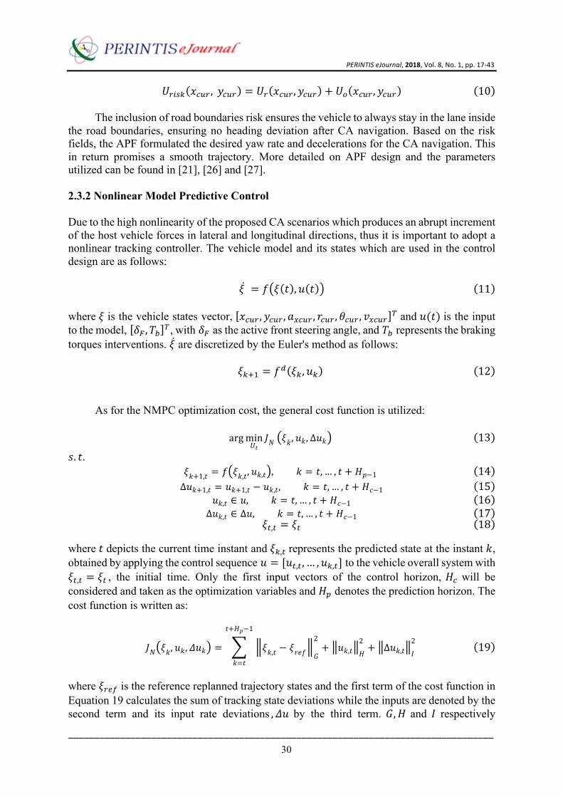
𝑈3QR: 𝑥?@3, 𝑦?@3 = 𝑈3 𝑥?@3, 𝑦?@3 + 𝑈M 𝑥?@3, 𝑦?@3 10 The inclusion of road boundaries risk ensures the vehicle to always stay in the lane inside
the road boundaries, ensuring no heading deviation after CA navigation. Based on the risk fields, the APF formulated the desired yaw rate and decelerations for the CA navigation. This in return promises a smooth trajectory. More detailed on APF design and the parameters utilized can be found in [21], [26] and [27].
2.3.2 Nonlinear Model Predictive Control Due to the high nonlinearity of the proposed CA scenarios which produces an abrupt increment of the host vehicle forces in lateral and longitudinal directions, thus it is important to adopt a nonlinear tracking controller. The vehicle model and its states which are used in the control design are as follows:
𝜉 = 𝑓 𝜉 𝑡 , 𝑢 𝑡 11 where 𝜉 is the vehicle states vector, 𝑥?@3, 𝑦?@3, 𝑎"?@3, 𝑟?@3, 𝜃?@3, 𝑣"?@3 W and 𝑢(𝑡) is the input to the model, 𝛿Y, 𝑇[ W, with 𝛿Y as the active front steering angle, and 𝑇[ represents the braking torques interventions. 𝜉 are discretized by the Euler's method as follows:
𝜉:\] = 𝑓^ 𝜉:, 𝑢: 12
As for the NMPC optimization cost, the general cost function is utilized:
argmin𝑈𝑡
𝐽𝑁 𝜉𝑘, 𝑢𝑘, Δ𝑢𝑘 13
𝑠. 𝑡. 𝜉𝑘+1,𝑡 = 𝑓 𝜉𝑘,𝑡, 𝑢𝑘,𝑡 , 𝑘 = 𝑡, … , 𝑡 + 𝐻𝑝−1 14 Δ𝑢𝑘+1,𝑡 = 𝑢𝑘+1,𝑡 − 𝑢𝑘,𝑡, 𝑘 = 𝑡, … , 𝑡 + 𝐻𝑐−1 15
𝑢𝑘,𝑡 ∈ 𝑢, 𝑘 = 𝑡, … , 𝑡 + 𝐻𝑐−1 16 Δ𝑢𝑘,𝑡 ∈ Δ𝑢, 𝑘 = 𝑡, … , 𝑡 + 𝐻𝑐−1 17
𝜉&,& = 𝜉& 18
where 𝑡 depicts the current time instant and 𝜉:,&represents the predicted state at the instant 𝑘, obtained by applying the control sequence 𝑢 = [𝑢&,&, … , 𝑢:,&] to the vehicle overall system with 𝜉&,& = 𝜉& , the initial time. Only the first input vectors of the control horizon, 𝐻? will be considered and taken as the optimization variables and 𝐻o denotes the prediction horizon. The cost function is written as:
𝐽𝑁 𝜉𝑘, 𝑢𝑘, 𝛥𝑢𝑘 = 𝜉𝑘,𝑡 − 𝜉𝑟𝑒𝑓 𝐺
2+ 𝑢𝑘,𝑡 𝐻
2+ Δ𝑢𝑘,𝑡 𝐼
2𝑡+𝐻𝑝−1
𝑘=𝑡
19
where 𝜉3t1 is the reference replanned trajectory states and the first term of the cost function in Equation 19 calculates the sum of tracking state deviations while the inputs are denoted by the second term and its input rate deviations , 𝛥𝑢 by the third term. 𝐺,𝐻 and 𝐼 respectively

PERINTISeJournal,2018,Vol.8,No.1,pp.17-43
__________________________________________________________________________________
31
represents the weighting matrices of appropriate dimensions. 𝐺 helps the first term in penalizing the errors from the reference trajectory while 𝐻 works to help the second term in preventing any sudden control increment. With the formulations, NMPC is expected to produce the required front steering angle and braking torques for CA navigation, based on the online risk calculated by APF. More details can be found in [15, 21]. 2.3.3 Nominal Weighting Parameters The nominal weighting parameters for the vehicle state matrices used in the NMPC optimization cost (Equation 19) are tuned based on the nominal condition of the CA simulation, which is a single-seated passenger host vehicle. The parameters are written in Table 1.
Table 1 Nominal NMPC Weighting Parameters Symbol Unit Value 𝑇R 𝑠 0.015 𝐻o − 13 𝐻? − 9 𝐻 − 𝑑𝑖𝑎𝑔 0.02, 0.0004 𝐺 − 𝑑𝑖𝑎𝑔(0, 3.8, 8.5, 12, 30, 1.3) 𝐼 − 𝑑𝑖𝑎𝑔(0.02, 0.0004)
3.0 SIMULATION AND RESULTS In this section, the computational simulation details for the CA architecture in Figure 2 are written. The architecture is validated with two proposed scenarios. In the first scenario, the vehicle is avoiding a stranded vehicle at the roadside, when suddenly a pedestrian appearing, as shown in Figure 3 (a). While in Figure 3 (b), the second scenario is shown where a sudden appearing moving vehicle appeared crossing an intersection. The moving vehicle is previously hidden from driver's view by a wall. Scenario 2 causes the high nonlinearity increments in the vehicle dynamics. The host vehicle will avoid the obstacle by implementing both steering angle and braking torques in the two situations. For both scenarios, the host vehicle is moving with an initial speed of 60𝑘𝑚/ℎ and 85𝑘𝑚/ℎ, respectively.
The robustness of the controller design is evaluated based on these variations of host vehicle loads: (i) nominal kerb weight (vehicle with driver), (ii) five-seated passengers which give increment of 20% to the vehicle weight and (iii) fully-seated passengers with luggage which increase 36% of the vehicle weight. For each scenario, they are initially simulated with nominal tuning parameters (Table 1). The resulting CA navigation is analyzed, and with the results, the weighting parameters will be retuned relative to the findings. The states which need to be penalized further to allow for a robust CA navigation will also be identified.

PERINTISeJournal,2018,Vol.8,No.1,pp.17-43
__________________________________________________________________________________
32
Figure 3 Illustration of the proposed Collision Avoidance Scenario, where (a) and (b) each represents the first and second scenario 3.1 Simulation Parameters In this section, the parameters of the vehicle, as well as its loads, are presented. Since the CA designs are based on our previous works in [21] and [26], thus the detailed parameters of the system are omitted from the literature and can be retrieved from the mentioned sources. The host vehicle's physical dimension is denoted in Table 2:
Table 2 Host Vehicle Parameter Parameter Symbol Value
Mass (Kerb Weight) 𝑚& 1486𝑘𝑔 Width 𝑤 1.8𝑚
Yaw Inertia 𝐽7 6286𝑘𝑔|} COG length towards frontal part 𝑙1 1.26𝑚
COG length towards rear part 𝑙3 1.90𝑚
For the passengers' body mass, the values are given as below and are taken from [28]. According to the work, out of 4630million adults in the world, the average body mass for an adult human is 62.0𝑘𝑔. Thus, for this work, the value is taken as the weight for each passenger.
Table 3 Average Adult Human Body Mass [28]
World Health Organization Region
Adult Population (Millions) Average Body Mass (kg)
World 4630 62.0 In addition, for fully-seated passengers, two luggage weigh 50𝑘𝑔 each are placed inside
the vehicle.
3.2 Architecture Performance with Nominal NMPC Parameters Since the focus of this work is not on the architecture design [21, 26], the simulation results only analyze the performance of the CA trajectory for each scenario with varied loads. The
PERINTISeJournal,2018,Vol.8,No.1,pp.17-43
__________________________________________________________________________________
33
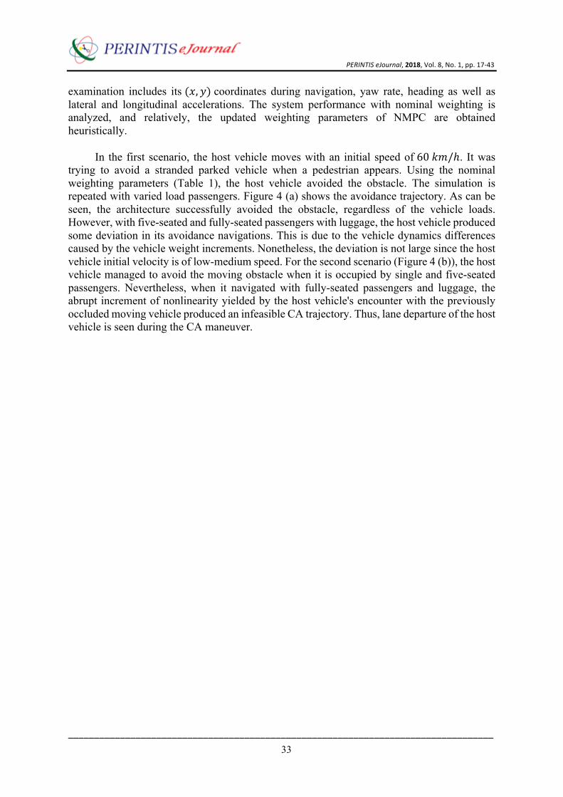
examination includes its(𝑥, 𝑦)coordinates during navigation, yaw rate, heading as well as lateral and longitudinal accelerations. The system performance with nominal weighting is analyzed, and relatively, the updated weighting parameters of NMPC are obtained heuristically.
In the first scenario, the host vehicle moves with an initial speed of 60𝑘𝑚/ℎ. It was trying to avoid a stranded parked vehicle when a pedestrian appears. Using the nominal weighting parameters (Table 1), the host vehicle avoided the obstacle. The simulation is repeated with varied load passengers. Figure 4 (a) shows the avoidance trajectory. As can be seen, the architecture successfully avoided the obstacle, regardless of the vehicle loads. However, with five-seated and fully-seated passengers with luggage, the host vehicle produced some deviation in its avoidance navigations. This is due to the vehicle dynamics differences caused by the vehicle weight increments. Nonetheless, the deviation is not large since the host vehicle initial velocity is of low-medium speed. For the second scenario (Figure 4 (b)), the host vehicle managed to avoid the moving obstacle when it is occupied by single and five-seated passengers. Nevertheless, when it navigated with fully-seated passengers and luggage, the abrupt increment of nonlinearity yielded by the host vehicle's encounter with the previously occluded moving vehicle produced an infeasible CA trajectory. Thus, lane departure of the host vehicle is seen during the CA maneuver.

PERINTISeJournal,2018,Vol.8,No.1,pp.17-43
__________________________________________________________________________________
34
Figure 4 Performance of the host vehicle CA system with Nominal Parameters for Scenario 1 (a) and Scenario 2 (b) for all variation of vehicle loads
To obtain robust parameters for the system which can solve the aforementioned issues,
the host vehicle dynamics during the CA navigation with nominal NMPC parameters in all collision scenarios with varied loads are analyzed. The most affected vehicle states in the evaluations are identified. The information will be used to update the NMPC weighting parameters afterward.
To allow the readers to have a better understanding, the vehicle collision avoidance
behaviors with nominal NMPC weighting parameters (Dotted Red Lines) in comparison to the updated NMPC weighting parameters (Blue Lines) are plotted in Figures 5 and 6. However, the details for the updated NMPC weighting parameters will only be discussed in the next section.

PERINTISeJournal,2018,Vol.8,No.1,pp.17-43
__________________________________________________________________________________
35
Figure 5 Comparisons of the Host Vehicle States and Control Actuations during Collision Avoidance of Scenario 1 using Nominal Parameters and Updated Parameters. Red Dotted Line depicts the nominal parameters performance, while Blue Line illustrates the host vehicle performance with updated NMPC weighting parameters

PERINTISeJournal,2018,Vol.8,No.1,pp.17-43
__________________________________________________________________________________
36
Figure 6 Comparisons of the Host Vehicle States and Control Actuations during Collision Avoidance of Scenario 2 using Nominal Parameters and Updated Parameters. Red Dotted Line depicts the nominal parameters performance, while Blue Line illustrates the host vehicle performance with updated NMPC weighting parameters
For Scenario 1, with single-seated passengers (the left column in Figure 5, the nominal
parameters managed to guide the host vehicle to avoid the parked vehicle and moving pedestrian. During the navigation of five-seated passengers (Middle Column) and fully-seated passengers with luggage (Right Column), the increment of the vehicle mass resulted in the instability of the yaw rate after the avoidance. This in return created the non-optimal trajectory shown in Figure 4 (a). The changes in lateral dynamics of the heavier host vehicle yield a delay in steering actuation. However, due to the simplicity of the scenario, the vehicle is still managed to navigate the CA trajectory despite the delay. For longitudinal motions, as can be seen in

PERINTISeJournal,2018,Vol.8,No.1,pp.17-43
__________________________________________________________________________________
37
Figures 5 and 6, the increment in vehicle weight does not affect its 𝑎" heavily compared to the lateral motions.
Contrary to Scenario 1, Scenario 2 is a highly nonlinear scenario. As can be seen by the
vehicle states during the navigation (Figure 6), large heading changes are needed in short period to enable the CA maneuver. However, for the fully-seated passengers vehicle with luggage, the nonlinearity is inflated with the increased vehicle mass. The addition of vehicle loads affects the performance of CA navigation. When the vehicle navigated with fully-seated passengers and luggage, CA interventions could not be applied by the system. Consequently, an infeasible trajectory is evident in Figure 4 (b), where the steering angle is over-actuated due to the increased nonlinearity allowing the vehicle to slide away from the original path before avoiding the collisions. However, for the host vehicle with kerb weight (Figure 6 (Left Column)) and five-seated passengers (Figure 6 (Middle Column)), the navigation is feasible with the nominal NMPC weighting parameters. In spite of that, similar to Scenario 1, the longitudinal motions of the host vehicle are less affected by the various loads. As can be seen, in all situations, the host vehicle successfully provides braking intervention prior to the steering actuation (Figure 6). 3.3 Architecture Performance with Updated NMPC Parameters From the gain sensitivity analyses in the previous section, it is identified, that during the navigation in both scenarios, the lateral dynamics of the host vehicle are shown to be more mercurial and affected to the varied host vehicle loads compared to its longitudinal behavior. Based on this, the NMPC parameters are updated. The updated nominal NMPC parameters are given in Tables 4 and 5.
Table 4 Updated NMPC Weighting Parameters for Scenario 1 Symbol Unit Value 𝑇R 𝑠 0.015 𝐻o − 13 𝐻? − 9 𝐻 − 𝑑𝑖𝑎𝑔 0.02, 0.0004 𝐺 − 𝑑𝑖𝑎𝑔(0, 3.8, 8.5, 15, 30, 1.3) 𝐼 − 𝑑𝑖𝑎𝑔(0.02, 0.0004)
Table 5 Updated NMPC Weighting Parameters for Scenario 2
Symbol Unit Value 𝑇R 𝑠 0.015 𝐻o − 13 𝐻? − 9 𝐻 − 𝑑𝑖𝑎𝑔 0.01, 0.0004 𝐺 − 𝑑𝑖𝑎𝑔(0, 3.8, 8.5, 30, 40, 1.3) 𝐼 − 𝑑𝑖𝑎𝑔(0.01, 0.0004)
For Scenario 1 (Table 4), the increment is in the lateral states error penalization (i.e.
yaw and heading angle). Due to the scenario is of low-medium speed, the increment is small in relation to the nominal parameters. However, the small increments are not valid for Scenario 2 (Table 5). The larger yaw and heading deviations demand larger gains. This is due to the

PERINTISeJournal,2018,Vol.8,No.1,pp.17-43
__________________________________________________________________________________
38
higher host vehicle initial speeds as well as the nonlinearity of the scenario. In addition to that, for Scenario 2, to allow reliable tracking by NMPC, a harder gain is given to the active steering angle to enforce the maneuver.
Though this section can be simplified by simply applying the Updated Parameters for
Scenario 2 for both scenarios, however, these findings are still jotted down to give the idea to the readers and researchers in this field about the importance of gain sensitivity to the NMPC performance. Different scenario nonlinearity demands different gain parameters. The performance with the updated NMPC parameters are shown in Figures 5-7.
With the updated parameters, it is shown that the vehicle is robust enough during
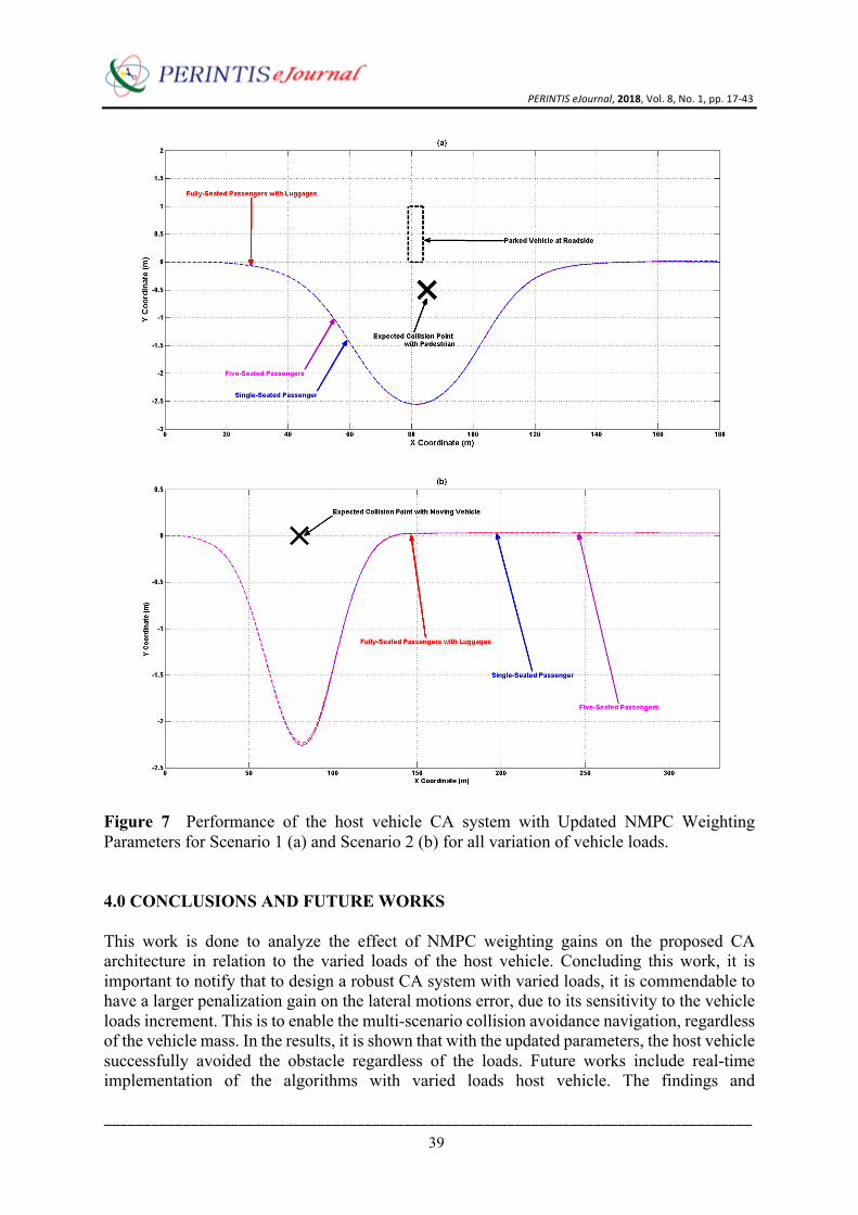
navigation with each loads variant for the Scenario 1 Collision Avoidance. The vehicle states and control actuations using the updated NMPC weighting parameters for the scenario are shown in Figure 5 (Blue Line). As can be seen, the updated parameters managed to aid the host vehicle in diminishing the heading deviations during the avoidance for all vehicle loads variations. For Scenario 2, due to the more complex obstacle emergence and avoidance, the updated parameters are of larger values. From the vehicle states shown in Figure 6 (Blue Line), the steering angle and braking torques managed to output desired metrics for the automated motion guidance. However, for the updated gains, there are trade-offs for the CA performance where some spikes occurred to the lateral accelerations during the avoidance. These are due to the higher vehicle velocities for the second scenario. This can be reduced by assimilating a spike control strategy into the system. Using the Updated NMPC weighting parameters, the host vehicle managed to avoid the obstacles in all scenarios, regardless of its loads. The avoidance trajectory using the updated gains are shown in Figure 7, where the architecture yielded a feasible collision avoidance maneuver for the host vehicle, regardless of the vehicle loads.
PERINTISeJournal,2018,Vol.8,No.1,pp.17-43
__________________________________________________________________________________
39
Figure 7 Performance of the host vehicle CA system with Updated NMPC Weighting Parameters for Scenario 1 (a) and Scenario 2 (b) for all variation of vehicle loads.
4.0 CONCLUSIONS AND FUTURE WORKS This work is done to analyze the effect of NMPC weighting gains on the proposed CA architecture in relation to the varied loads of the host vehicle. Concluding this work, it is important to notify that to design a robust CA system with varied loads, it is commendable to have a larger penalization gain on the lateral motions error, due to its sensitivity to the vehicle loads increment. This is to enable the multi-scenario collision avoidance navigation, regardless of the vehicle mass. In the results, it is shown that with the updated parameters, the host vehicle successfully avoided the obstacle regardless of the loads. Future works include real-time implementation of the algorithms with varied loads host vehicle. The findings and

PERINTISeJournal,2018,Vol.8,No.1,pp.17-43
__________________________________________________________________________________
40
understandings from this work are beneficial for a lot of future works involving path tracking, collision avoidance as well as vehicle dynamics in the context of Advanced Driver Assistance System fields. In addition, complementing the works, adaptive NMPC online tuning will be explored for a more reliable navigation.
Acknowledgement The work presented in this study is funded by Ministry of Higher Education, Malaysia and Research University Grant, Universiti Teknologi Malaysia. VOTE NO: 13H73. This work is also supported by PROTON Holdings Berhad. References
[1] Anderson, J.M., Nidhi, K., Stanley, K.D., Sorensen, P., Samaras, C. and Oluwatola, O.A., 2014. Autonomous vehicle technology: A guide for policymakers. Rand Corporation.
[2] Bauer, E., Lotz, F., Pfromm, M., Schreier, M., Abendroth, B., Cieler, S., Eckert, A., Hohm, A., Lüke, S., Rieth, P. and Willert, V., 2012. Proreta 3: An integrated approach to collision avoidance and vehicle automation. at-Automatisierungstechnik Methoden und Anwendungen der Steuerungs-, Regelungs-und Informationstechnik, 60(12), pp.755-765. DOI: https://doi.org/10.1524/auto.2012.1046
[3] Bengler, K., Dietmayer, K., Farber, B., Maurer, M., Stiller, C. and Winner, H., 2014. Three decades of driver assistance systems: Review and future perspectives. IEEE Intelligent Transportation Systems Magazine, 6(4), pp.6-22 DOI: https://doi.org/10.1109/MITS.2014.2336271
[4] Volvo launches M, its own mobility company - https://www.cnet.com/roadshow/news/volvo-m-mobility-company/ - RoadShow by CNET; accessed July 05 2018.
[5] Hamid, U.Z.A., Pushkin, K., Zamzuri, H., Gueraiche, D. and Rahman, M.A.A., 2016. Current Collision Mitigation Technologies for Advanced Driver Assistance Systems–A Survey. PERINTIS eJournal, 6(2)
[6] Inoue, H., Raksincharoensak, P. and Inoue, S., 2017. Intelligent Driving System for Safer Automobiles. Journal of Information Processing, 25, pp.32-43. DOI: http://doi.org/10.2197/ipsjjip.25.32

PERINTISeJournal,2018,Vol.8,No.1,pp.17-43
__________________________________________________________________________________
41
[7] Mosquet, X., Andersen, M. and Arora, A., 2016. A roadmap to safer driving through advanced driver assistance systems. Auto Tech Review, 5(7), pp.20-25 DOI: 10.1365/s40112-016-1164-1
[8] Falcone, P., Borrelli, F., Asgari, J., Tseng, H.E. and Hrovat, D., 2007. Predictive active steering control for autonomous vehicle systems. IEEE Transactions on control systems technology, 15(3), pp.566-580 DOI: https://doi.org/10.1109/TCST.2007.894653
[9] Matthaei, R. and Maurer, M., 2015. Autonomous driving–a top-down-approach. at-Automatisierungstechnik, 63(3), pp.155-167 DOI: https://doi.org/10.1515/auto-2014-1136
[10] Balachandran, A., Brown, M., Erlien, S.M. and Gerdes, J.C., 2015, June. Creating predictive haptic feedback for obstacle avoidance using a model predictive control (MPC) framework. In Intelligent Vehicles Symposium (IV), 2015 IEEE (pp. 31-36). IEEE. DOI: https://doi.org/10.1109/IVS.2015.7225658
[11] Balachandran, A., Brown, M., Erlien, S.M. and Gerdes, J.C., 2016. Predictive haptic feedback for obstacle avoidance based on model predictive control. IEEE Transactions on Automation Science and Engineering, 13(1), pp.26-31. DOI: https://doi.org/10.1109/TASE.2015.2498924
[12] Hamid, U.Z.A., Zakuan, F.R.A., Zulkepli, K.A., Azmi, M.Z., Zamzuri, H., Rahman, M.A.A. and Zakaria, M.A., 2018, April. Multi-actuators vehicle collision avoidance system-Experimental validation. In IOP Conference Series: Materials Science and Engineering (Vol. 342, No. 1, p. 012018). IOP Publishing.
[13] Saito, Y. and Raksincharoensak, P., 2016, June. Risk predictive shared deceleration control: Its functionality and effectiveness of an early intervention support. In Intelligent Vehicles Symposium (IV), 2016 IEEE (pp. 49-54). IEEE. DOI: https://doi.org/10.1109/IVS.2016.7535363
[14] Hayashi, R., Isogai, J., Raksincharoensak, P. and Nagai, M., 2012. Autonomous collision avoidance system by combined control of steering and braking using geometrically optimised vehicular trajectory. Vehicle system dynamics, 50(sup1), pp.151-168. DOI: http://dx.doi.org/10.1080/00423114.2012.672748

PERINTISeJournal,2018,Vol.8,No.1,pp.17-43
__________________________________________________________________________________
42
[15] Hamid, U.Z.A., Ariff, M.H.M., Zamzuri, H., Saito, Y., Zakaria, M.A., Rahman, M.A.A. and Raksincharoensak, P., 2018. Piecewise trajectory replanner for highway collision avoidance systems with safe-distance based threat assessment strategy and nonlinear model predictive control. Journal of Intelligent & Robotic Systems, 90(3-4), pp.363-385.
[16] Ji, J., Khajepour, A., Melek, W.W. and Huang, Y., 2017. Path Planning and Tracking for Vehicle Collision Avoidance Based on Model Predictive Control With Multiconstraints. IEEE Transactions on Vehicular Technology, 66(2), pp.952-964. DOI: https://doi.org/10.1109/TVT.2016.2555853
[17] Ismail, R., Hafezi, M.H., Nor, R.M. and Ambak, K., 2012. Passengers preference and satisfaction of public transport in Malaysia. Australian Journal of Basic and Applied Sciences, 6(8), pp.410-416.
[18] Fell, J., 2017. Cars of the future [Transport Concept Cars]. Engineering & Technology, 12(2), pp.48-53. DOI: https://doi.org/10.1049/et.2017.0204
[19] Ariffin, A.H., Jawi, Z.M., Ahmad, Y. and Solah, M.S., 2009. Malaysian Vehicle Assessment Programme PROTON–A 4-Star MPV in Safety. Malaysian Institute of Road Safety Research.
[20] Pacejka, H.B. and Bakker, E., 1992. The magic formula tyre model. Vehicle system dynamics, 21(S1), pp.1-18. DOI: http://dx.doi.org/10.1080/00423119208969994
[21] Abdul Hamid, U.Z., Zamzuri, H., Yamada, T., Abdul Rahman, M.A., Saito, Y. and Raksincharoensak, P., 2018. Modular design of artificial potential field and nonlinear model predictive control for a vehicle collision avoidance system with move blocking strategy. Proceedings of the Institution of Mechanical Engineers, Part D: Journal of Automobile Engineering, 232(10), pp.1353-1373.
[22] Shim, T., Adireddy, G. and Yuan, H., 2012. Autonomous vehicle collision avoidance system using path planning and model-predictive-control-based active front steering and wheel torque control. Proceedings of the Institution of Mechanical Engineers, Part D: Journal of automobile engineering, 226(6), pp.767-778. DOI: https://doi.org/10.1177/0954407011430275
PERINTISeJournal,2018,Vol.8,No.1,pp.17-43
__________________________________________________________________________________
43
[23] Yi, B., Ferdinand, J., Simm, N. and Bonarens, F., 2016. Application of Local Linear Steering Models with Model Predictive Control for Collision Avoidance Maneuvers. IFAC-PapersOnLine, 49(15), pp.187-192. DOI: https://doi.org/10.1016/j.ifacol.2016.07.730
[24] Ahmad, F., Mazlan, S.A., Zamzuri, H., Jamaluddin, H., Hudha, K. and Short, M., 2014. Modelling and validation of the vehicle longitudinal model. International Journal of Automotive and Mechanical Engineering, 10, p.2042. DOI: http://dx.doi.org/10.15282/ijame.10.2014.21.0172
[25] Liu, J., Jayakumar, P., Stein, J.L. and Ersal, T., 2016. A study on model fidelity for model predictive control-based obstacle avoidance in high-speed autonomous ground vehicles. Vehicle System Dynamics, 54(11), pp.1629-1650. DOI: http://dx.doi.org/10.1080/00423114.2016.1223863
[26] Raksincharoensak, P., Akamatsu, Y., Moro, K. and Nagai, M., 2014. Driver Speed Control Modeling for Predictive Braking Assistance System Based on Risk Potential in Intersections. Journal of Robotics and Mechatronics, 26(5), pp.628-637. DOI: 10.20965/jrm.2014.p0628
[27] Raksincharoensak, P., Hasegawa, T., Yamasaki, A., Mouri, H. and Nagai, M., 2016, March. Vehicle motion planning and control for autonomous driving intelligence system based on risk potential optimization framework. In The Dynamics of Vehicles on Roads and Tracks: Proceedings of the 24th Symposium of the International Association for Vehicle System Dynamics (IAVSD 2015), Graz, Austria, 17-21 August 2015 (p. 189). CRC Press.
[28] Walpole, S.C., Prieto-Merino, D., Edwards, P., Cleland, J., Stevens, G. and Roberts, I., 2012. The weight of nations: an estimation of adult human biomass. BMC public health, 12(1), p.439. DOI: 10.1186/1471-2458-12-439
Related Documents