Designing Pavement Subsurface Drainage Using DRIP Software Tuesday, October 23, 2018 2:00-4:00 PM ET TRANSPORTATION RESEARCH BOARD

Welcome message from author
This document is posted to help you gain knowledge. Please leave a comment to let me know what you think about it! Share it to your friends and learn new things together.
Transcript
Designing Pavement Subsurface Drainage Using DRIP Software
Tuesday, October 23, 20182:00-4:00 PM ET
TRANSPORTATION RESEARCH BOARD

The Transportation Research Board has met the standards and
requirements of the Registered Continuing Education Providers Program.
Credit earned on completion of this program will be reported to RCEP. A
certificate of completion will be issued to participants that have registered
and attended the entire session. As such, it does not include content that
may be deemed or construed to be an approval or endorsement by RCEP.

Purpose
Discuss how to use Drainage Requirements in Pavement (DRIP) software to design effective drainage systems for pavements.
Learning Objectives
At the end of this webinar, you will be able to:
• Discuss the DRIP software, its capabilities, and its potential benefits
• Identify the source of water entering the pavement and potential damage due to water entrapment
• Identify characteristics of a well-performing drainage system

Transportation Research Board webinar
Designing Pavement Subsurface Drainage Using DRIP Software
Sponsoring Committee: Subsurface Drainage (AFS60)Co-sponsoring Committee: Strength and Deformation Characteristics of Pavement
Sections (AFD80)
Tuesday, October 23, 20182:00 – 4:00

Presenters
• Mohamed Elfino, Ph. D, P.E., Virginia Department of Transportation (retired)• Gabriel Bazi, Ph.D, P.E., Assistant Professor, Lebanese American University• Clark Graves, Ph.D., P.E., P.G., Associate Director, Kentucky Transportation
Center
• Moderator: Affan Habib, P.E., State Pavement Program Manager, Virginia Department of Transportation
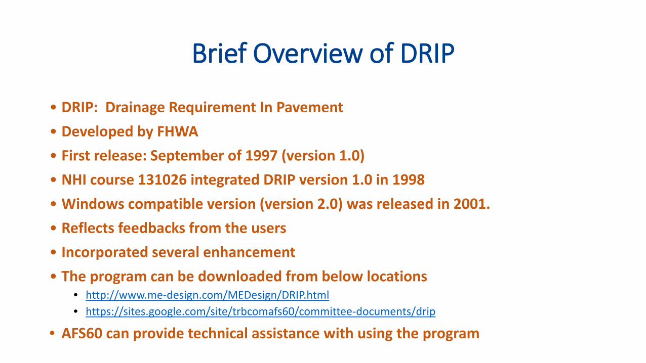
Brief Overview of DRIP
• DRIP: Drainage Requirement In Pavement• Developed by FHWA• First release: September of 1997 (version 1.0)• NHI course 131026 integrated DRIP version 1.0 in 1998• Windows compatible version (version 2.0) was released in 2001.• Reflects feedbacks from the users • Incorporated several enhancement• The program can be downloaded from below locations
• http://www.me-design.com/MEDesign/DRIP.html• https://sites.google.com/site/trbcomafs60/committee-documents/drip
• AFS60 can provide technical assistance with using the program

DRIP Capability
• Roadway geometry calculation• Sieve Analysis calculation• Inflow calculation• Permeable base design• Separator layer design• Edgedrain design

Importance of Effective Drainage in Enhancing Pavement Performance
Mohamed Elfino, PhD, PE“Retired”
Virginia Department of TransportationTRB AFS 60 Emeritus Member
TRB AFS 60 & AFD 80 Webinar
October 23, 2018
Outlines
• Sources of water entering the pavement.
• Impact of trapped water on pavement performance.
• Characteristics of effective drainage systems, Construction, and sample designs.


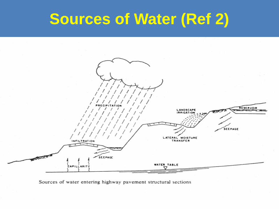
Sources of Water (Ref 2)

Points of Entrance of Water into Highway (Ref 2)

Why do We Need Drainage?

Impact of trapped water on pavement performance.

Moisture Distress Mechanism in Asphalt (Ref 2)

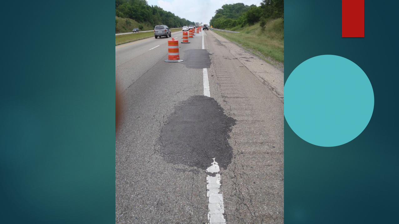
Severe Cracking and Rutting

Fatigue Cracking in Saturated Thin Asphalt Pavement

Water Seepage at the Interface, One hour after rain Stopped
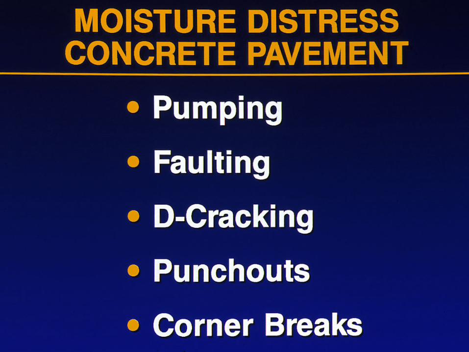
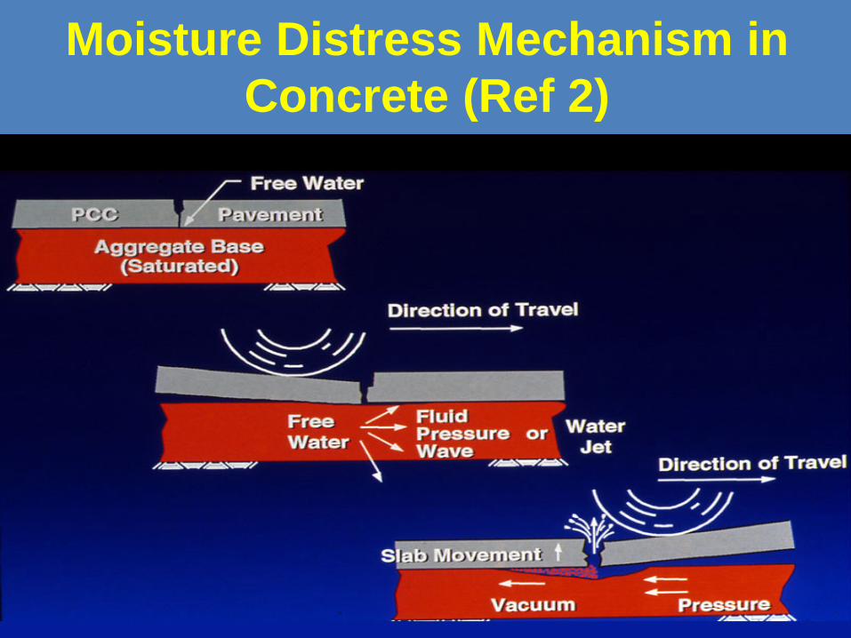
Moisture Distress Mechanism in Concrete (Ref 2)
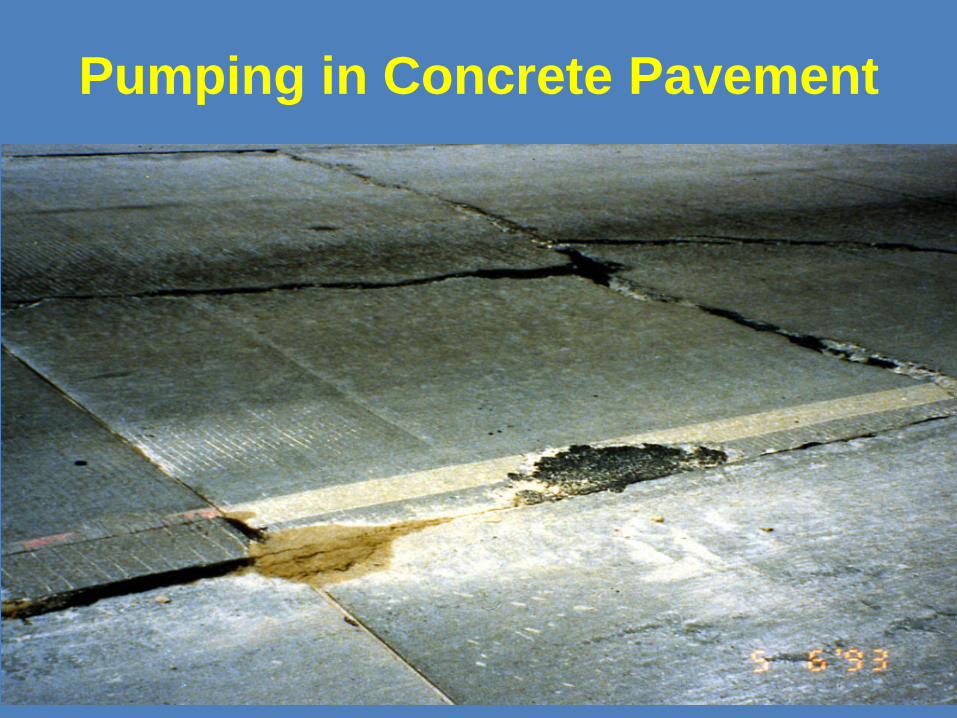
Pumping in Concrete Pavement

Cracking and Staining in Concrete Pavement
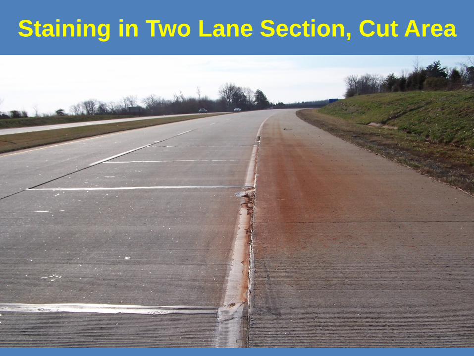
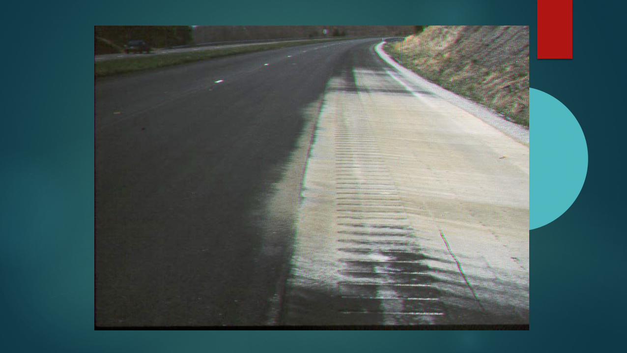
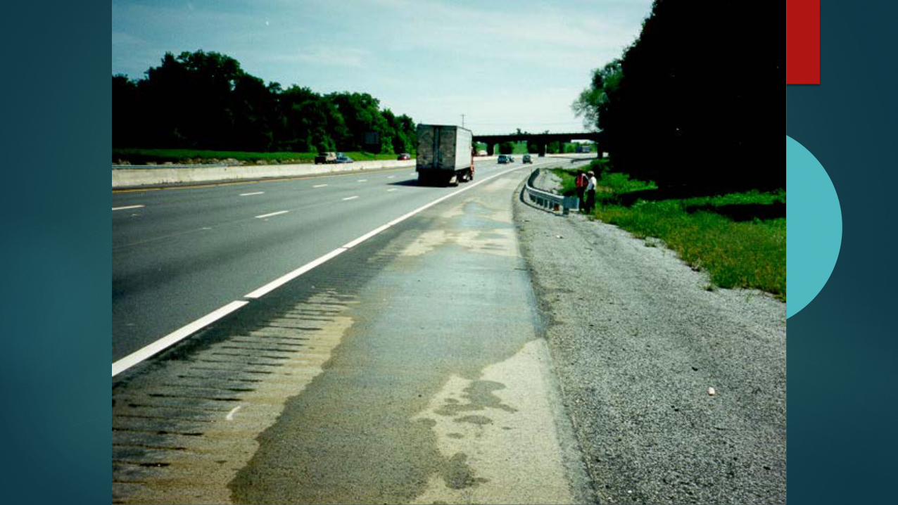
Staining in Two Lane Section, Cut Area
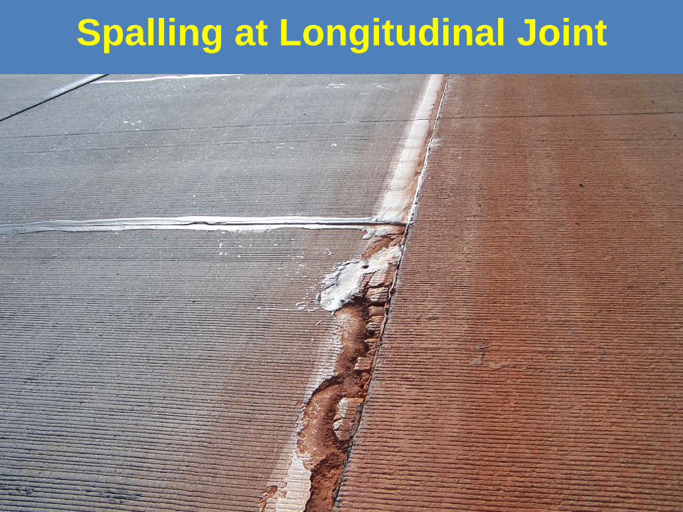
Spalling at Longitudinal Joint
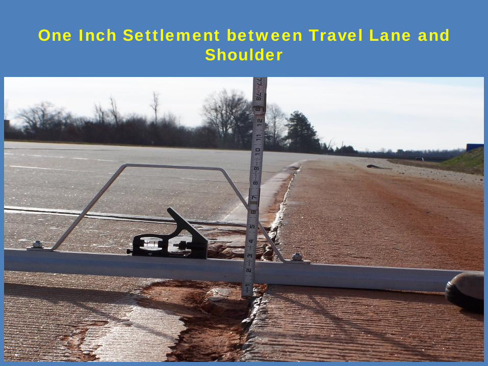
One Inch Settlement between Travel Lane and Shoulder

Spalling at the Transverse Joint 2007
Current National Effort
NCHRP Project 01-54
“ Guidelines for Limiting Damage to Flexible and Composite
Pavements Due to the Presence of Water”
Characteristics of effective drainage systems,
Construction, and sample designs.
Functions of Good Drainage System
Intercept
Collect
Discharge

Trenching Retrofitted Edgedrain

Laying out the Filter Fabric

Placing the Longitudinal perforated pipe
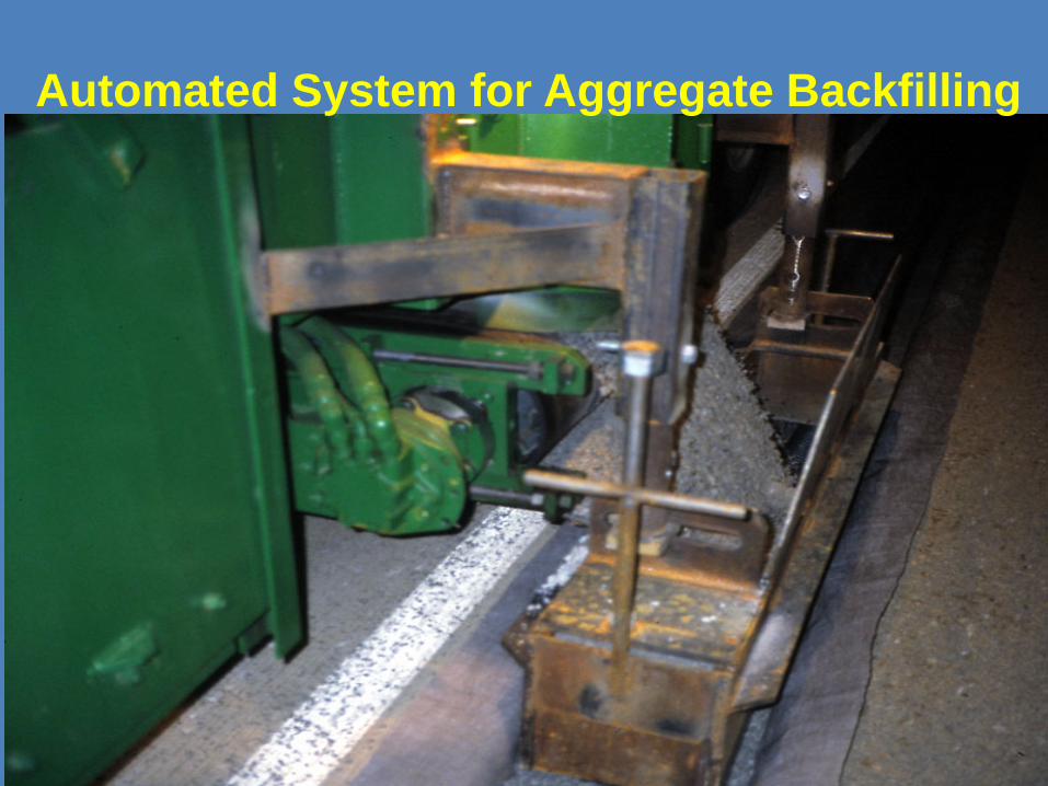
Automated System for Aggregate Backfilling
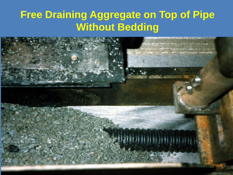
Free Draining Aggregate on Top of Pipe Without Bedding
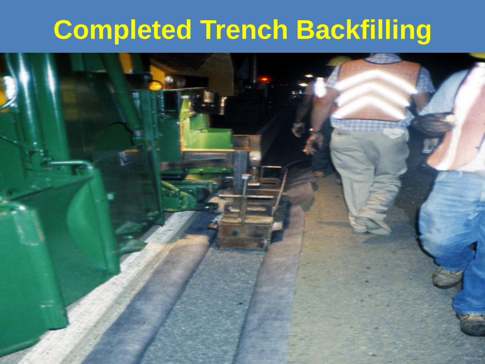
Completed Trench Backfilling
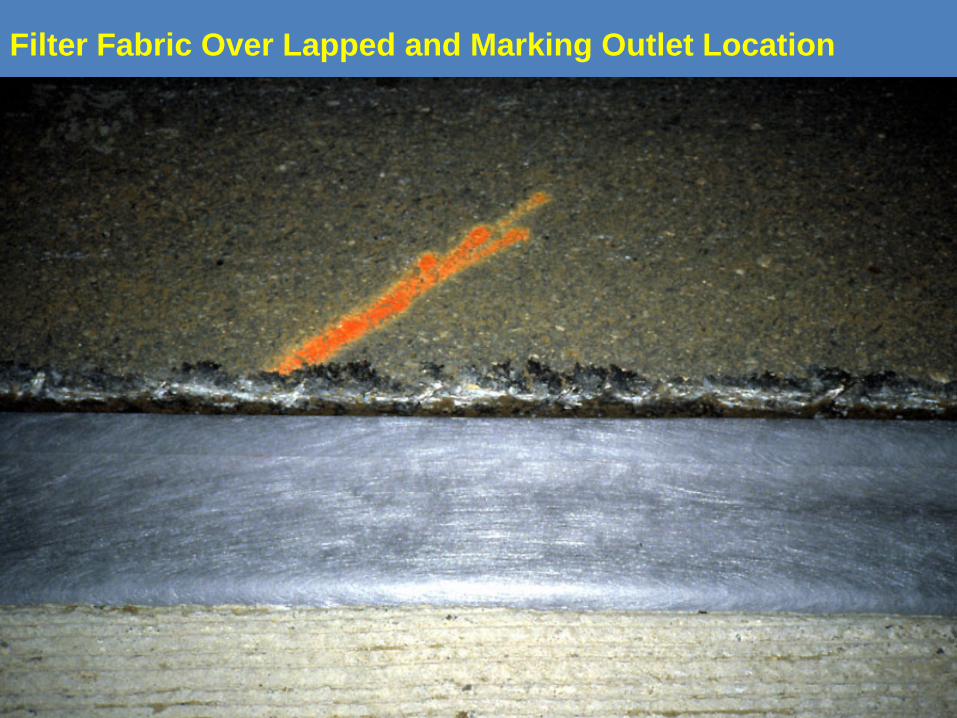
Filter Fabric Over Lapped and Marking Outlet Location
Types of Subsurface Drains in Virginia
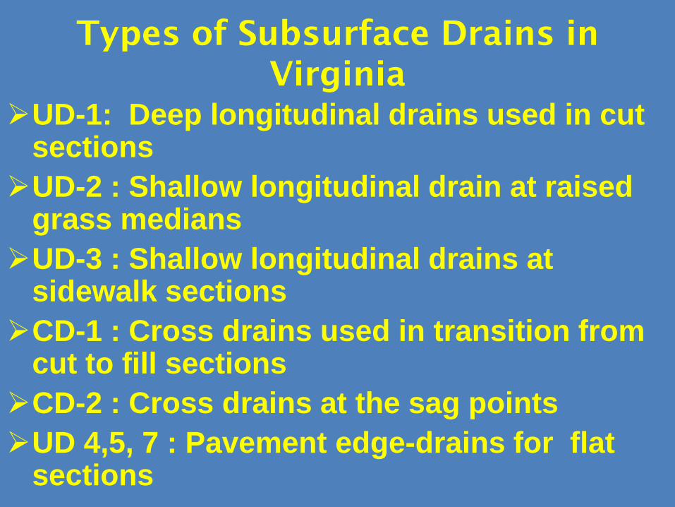
UD-1: Deep longitudinal drains used in cut sectionsUD-2 : Shallow longitudinal drain at raised
grass mediansUD-3 : Shallow longitudinal drains at
sidewalk sectionsCD-1 : Cross drains used in transition from
cut to fill sectionsCD-2 : Cross drains at the sag pointsUD 4,5, 7 : Pavement edge-drains for flat
sections
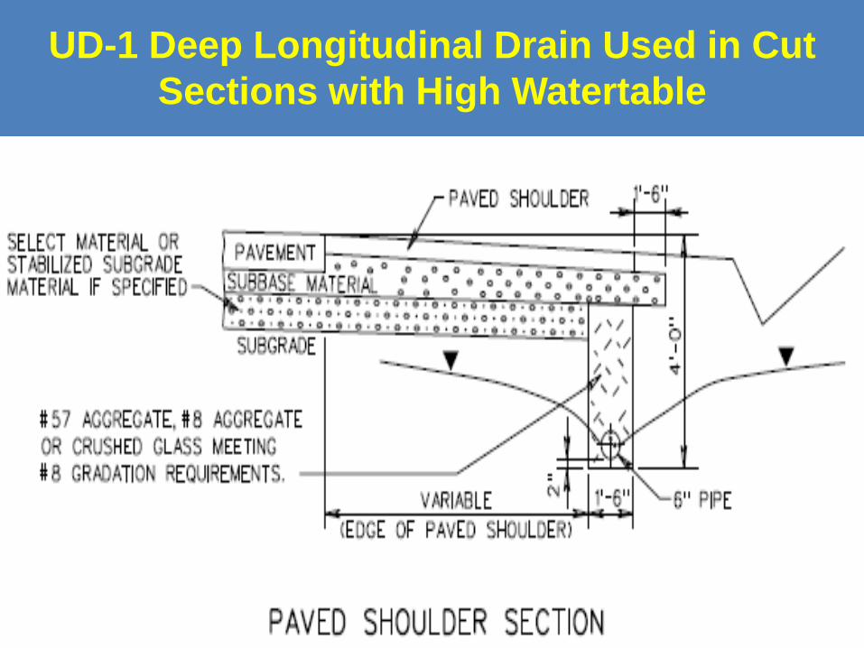
UD-1 Deep Longitudinal Drain Used in Cut Sections with High Watertable
33
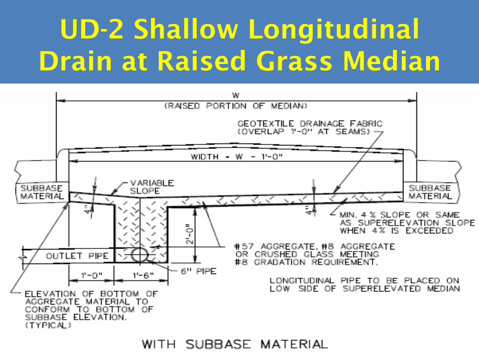
UD-2 Shallow Longitudinal Drain at Raised Grass Median
34
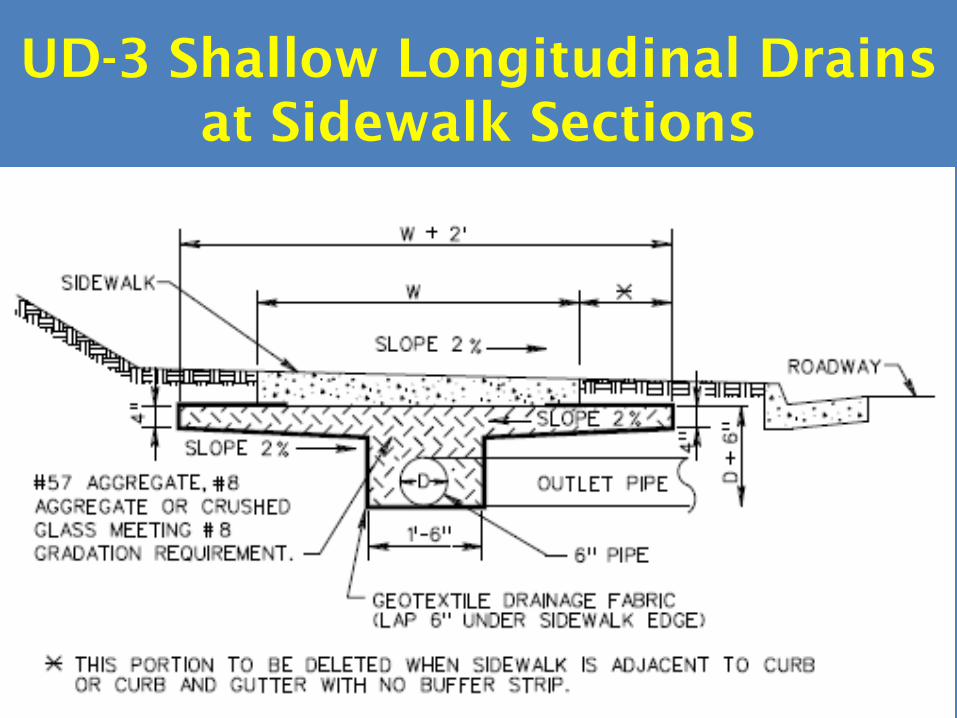
UD-3 Shallow Longitudinal Drains at Sidewalk Sections
35

CD-1 Cross Drain From Cut to Fill Sections
36

CD-1 Plan View
37
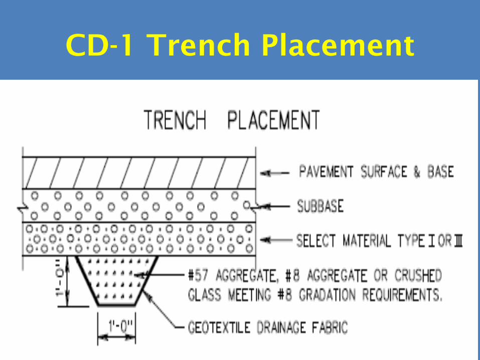
CD-1 Trench Placement
38

CD-2 Cross Drain for Sag Points
39

CD-2 Trench Placement
40

Outlet Pipe for UD-1,CD1or 2

UD-4 Pavement Edgedrain
42

UD-4 Pavement Edgedrain With OGDL
43
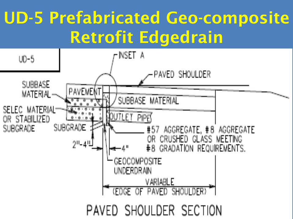
UD-5 Prefabricated Geo-composite Retrofit Edgedrain
44
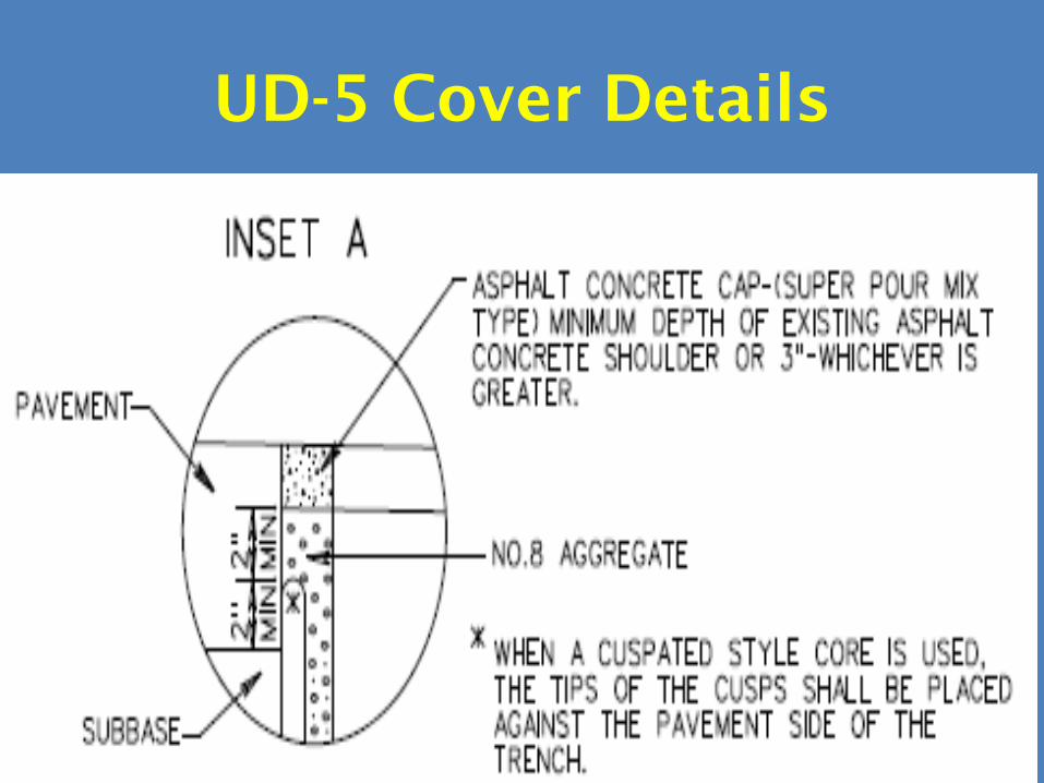
UD-5 Cover Details
45

UD-7 Retrofit Pavement Edgedrain
46

Outlet for Segmented Drainage System to Facilitate Inspection
47
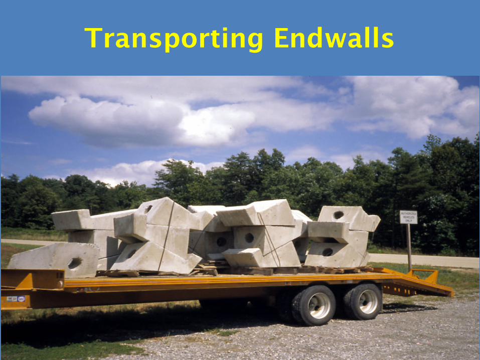
Transporting Endwalls
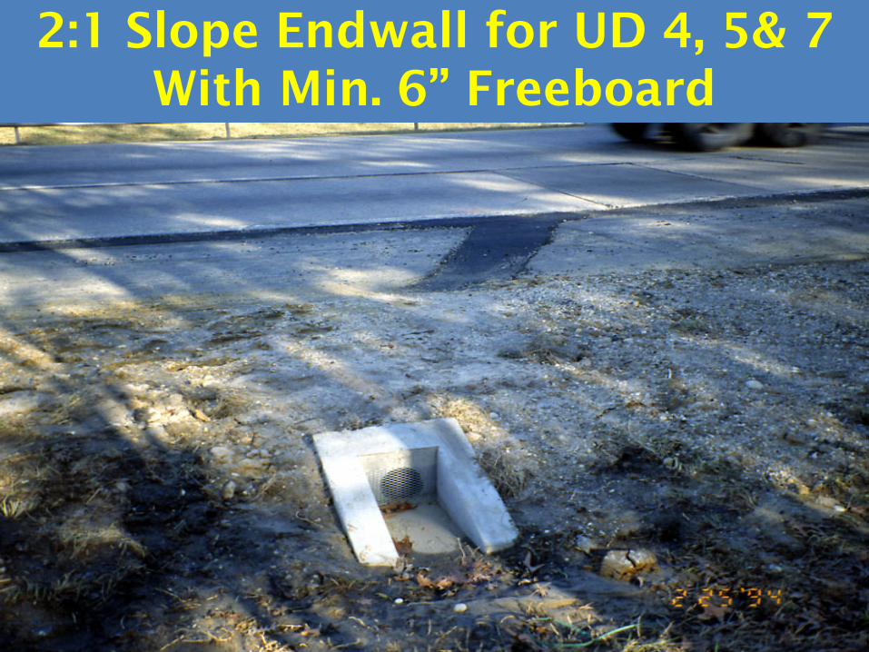
2:1 Slope Endwall for UD 4, 5& 7 With Min. 6” Freeboard

4:1 slope Endwall for UD-4,5 &7 with Min 6” freeboard

Typical Spacing between Outlets (300 ft)

Water Flowing from Outlet Pipe at Endwall

Water Flowing from Cross Drains
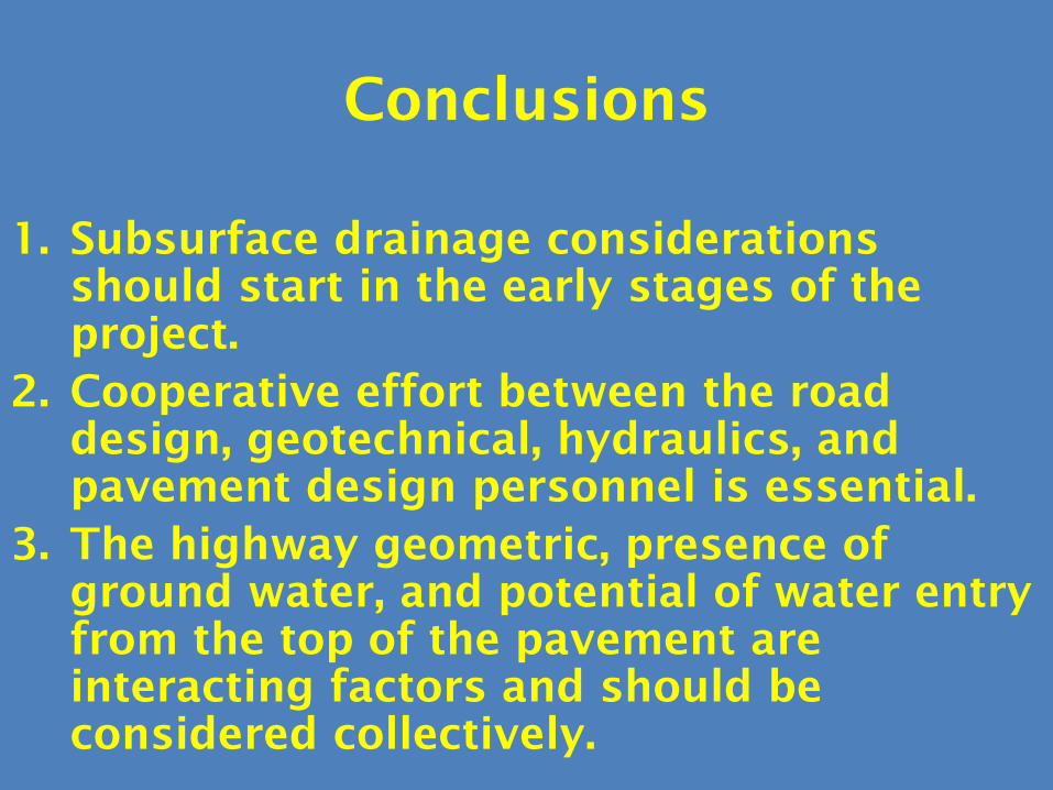
Conclusions
1. Subsurface drainage considerations should start in the early stages of the project.
2. Cooperative effort between the road design, geotechnical, hydraulics, and pavement design personnel is essential.
3. The highway geometric, presence of ground water, and potential of water entry from the top of the pavement are interacting factors and should be considered collectively.
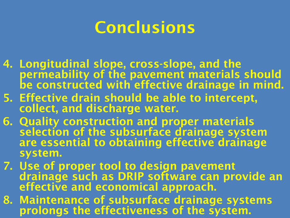
Conclusions
4. Longitudinal slope, cross-slope, and the permeability of the pavement materials should be constructed with effective drainage in mind.
5. Effective drain should be able to intercept, collect, and discharge water.
6. Quality construction and proper materials selection of the subsurface drainage system are essential to obtaining effective drainage system.
7. Use of proper tool to design pavement drainage such as DRIP software can provide an effective and economical approach.
8. Maintenance of subsurface drainage systems prolongs the effectiveness of the system.
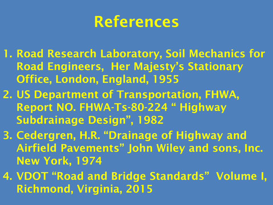
References
1. Road Research Laboratory, Soil Mechanics for Road Engineers, Her Majesty’s Stationary Office, London, England, 1955
2. US Department of Transportation, FHWA, Report NO. FHWA-Ts-80-224 “ Highway Subdrainage Design”, 1982
3. Cedergren, H.R. “Drainage of Highway and Airfield Pavements” John Wiley and sons, Inc. New York, 1974
4. VDOT “Road and Bridge Standards” Volume I, Richmond, Virginia, 2015

Thank You
Mohamed Elfino, PhD, PETRB Emeritus Member
(804) 908-3874

Designing Pavement Subsurface Drainage Using DRIP Software
TRB Webinar

DRIP
DRIP Capabilities
1. Moisture Infiltrating Pavement Structure
a) Rainfall
b) Meltwater
2Source: Moulton

DRIP
DRIP Capabilities
2. Permeable Base
3. Edge Drain
o Outlets
4. Separator
3
Shoulder
Permeable Base
Separator (Filter)1. Aggregate2. Geotextile
Pavement Surface
Edge Drain1. Pipe2. PGED
Outlet
DRIP
DRIP Software
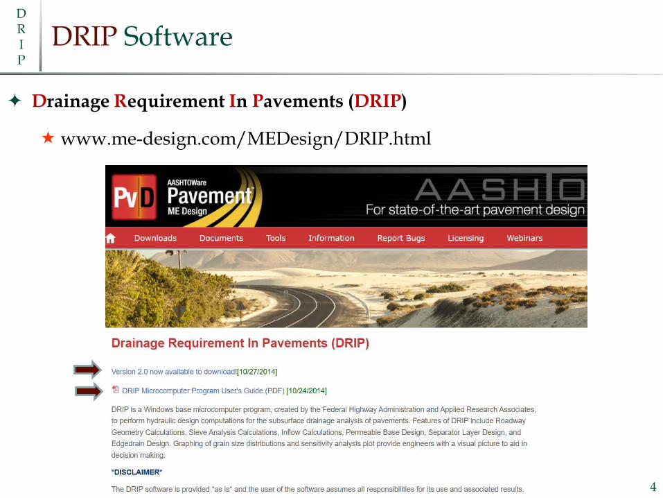
Drainage Requirement In Pavements (DRIP)
www.me-design.com/MEDesign/DRIP.html
4
DRIP
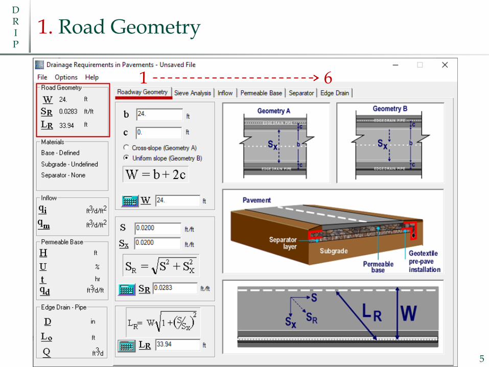
1. Road Geometry
5
1 6
DRIP
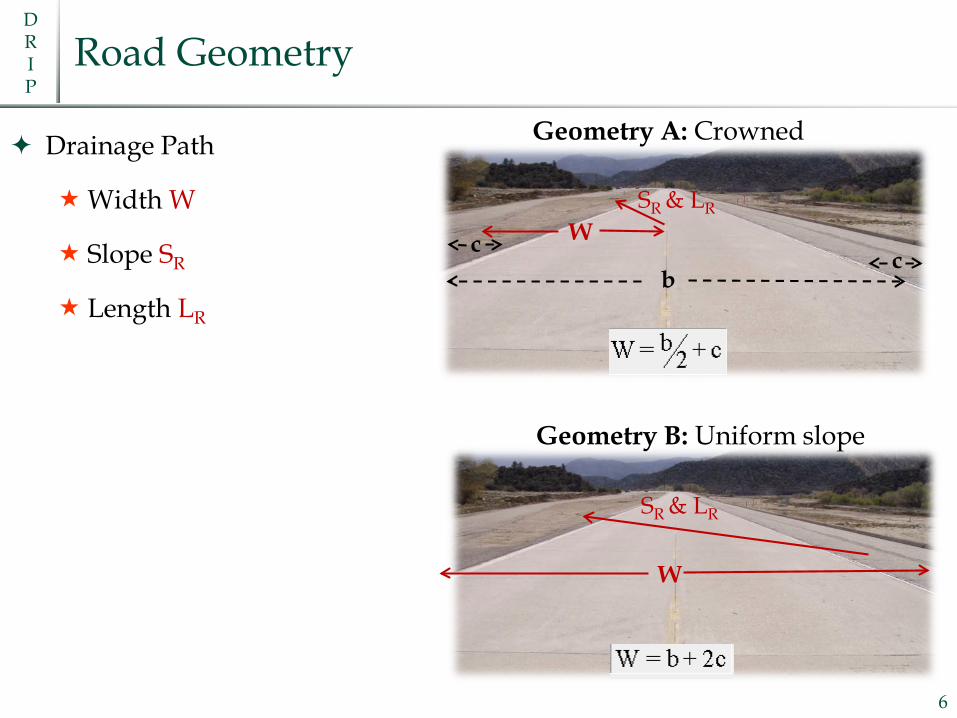
Road Geometry
Drainage Path
Width W
Slope SR
Length LR
6
SR & LR
Geometry B: Uniform slope
SR & LRW
Geometry A: Crowned
b
W
cc

DRIP
2. Sieve Analysis
7

DRIP
Effective Size D
DX = Effective size or grain size corresponding to X% passing
8
D50

DRIP
3. Inflow
9
DRIP
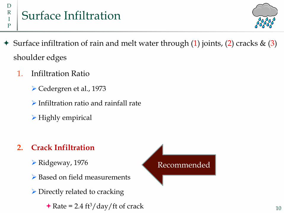
Surface Infiltration
Surface infiltration of rain and melt water through (1) joints, (2) cracks & (3)
shoulder edges
1. Infiltration Ratio
Cedergren et al., 1973
Infiltration ratio and rainfall rate
Highly empirical
2. Crack Infiltration
Ridgeway, 1976
Based on field measurements
Directly related to cracking
Rate = 2.4 ft3/day/ft of crack 10
Recommended

DRIP
Crack Infiltration Method
𝑞𝑞𝑖𝑖 = Rate of pavement infiltration (ft3/day/ft2)
𝐼𝐼𝑐𝑐 = Crack infiltration rate
2.4 ft3/day/ft (0.223 m3/day/m)
𝑊𝑊 = Width of drainage path 11
𝑞𝑞𝑖𝑖 =𝐼𝐼𝑐𝑐𝑊𝑊
𝑁𝑁𝑐𝑐 +𝑊𝑊𝑐𝑐
𝐶𝐶𝑠𝑠+ 𝑘𝑘𝑝𝑝
Surface joints/cracking
= 0

DRIP
Rigid Pavement
12
𝑞𝑞𝑖𝑖 =𝐼𝐼𝑐𝑐𝑊𝑊
𝑁𝑁𝑐𝑐 +𝑊𝑊𝑐𝑐𝐶𝐶𝑠𝑠
+ 𝑘𝑘𝑝𝑝
Surface joints/cracking
Longitudinal Joints/Cracks
o 𝑁𝑁𝑐𝑐 = Number
Transverse Joints/Cracks (contributing)
o 𝑊𝑊𝑐𝑐 = Length
o 𝐶𝐶𝑠𝑠 = Spacing
DRIP
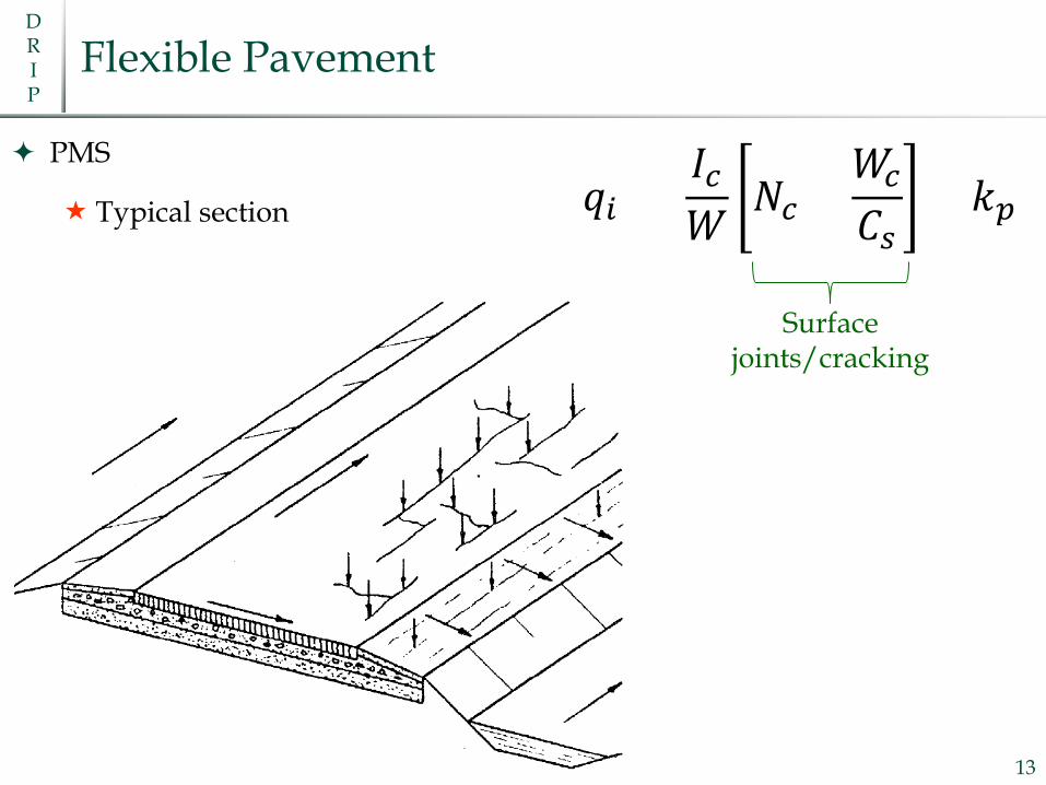
𝑞𝑞𝑖𝑖 =𝐼𝐼𝑐𝑐𝑊𝑊
𝑁𝑁𝑐𝑐 +𝑊𝑊𝑐𝑐𝐶𝐶𝑠𝑠
+ 𝑘𝑘𝑝𝑝
Flexible Pavement
PMS
Typical section
13
Surface joints/cracking

DRIP
4. Permeable Base
14

DRIP
Permeable Base Analysis
1. Time to Drain
From saturation to:
50% drained (AASHTO)
85% saturation (Pavement Rehabilitation Manual)
Time Calculation
Casagrande and Shannon (1952)
Barber and Sawyer (1952)
2. Depth of Flow
Moulton, 1979
Permeable base thickness ≥ Depth of flow
15
Conservative
AASHTO
DRIP
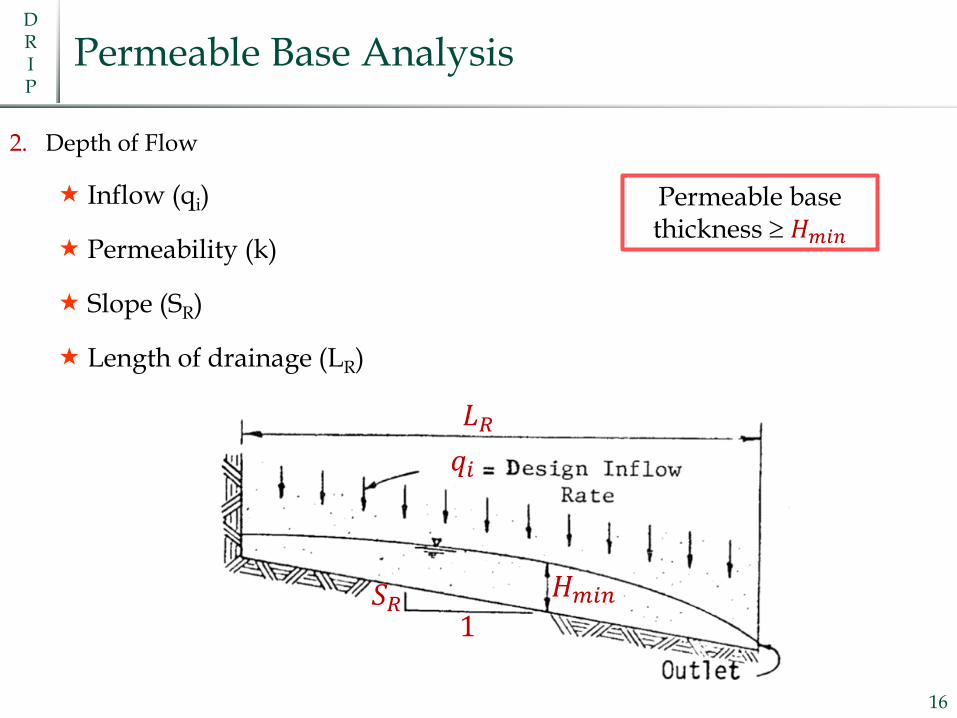
Permeable Base Analysis
2. Depth of Flow
Inflow (qi)
Permeability (k)
Slope (SR)
Length of drainage (LR)
16
𝑞𝑞𝑖𝑖
𝑆𝑆𝑅𝑅1
𝐿𝐿𝑅𝑅
𝐻𝐻𝑚𝑚𝑖𝑖𝑚𝑚
Permeable base thickness ≥ 𝐻𝐻𝑚𝑚𝑖𝑖𝑚𝑚

DRIP
5. Separator
17

DRIP
Separator
18
No Separator
Clogging
Parallel arrangement
Permeable BaseSubgrade

DRIP
Separator
19
Aggregate Separator
Clogging
Clogging
Parallel arrangement
Parallel arrangement
Passing No. 200
Permeable Base
SeparatorSubgrade

DRIP
Separator
Geotextile
Retention or pumping resistance
Permeability
Clogging
20
AOS = Apparent opening sizeo ASTM D4751o Defined as size of
glass beads when 5% pass through the geotextile
DRIP
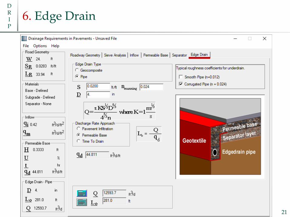
6. Edge Drain
21

DRIP
Edgedrains Design
Edgedrains can be designed for:
1. Pavement infiltration flow rate
2. Peak flow from the permeable base
o qd
o H, S and k
3. Average flow rate during the time to drain the permeable base22
Capacity of edgedrain ≥ Peak
capacity of permeable base
DRIP
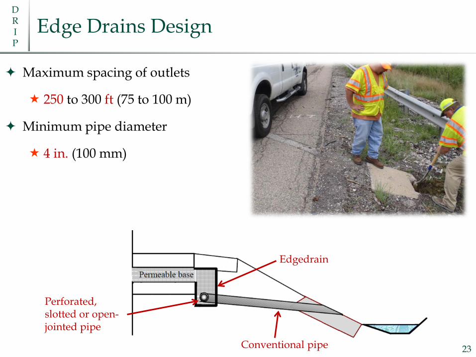
Edge Drains Design
Maximum spacing of outlets
250 to 300 ft (75 to 100 m)
Minimum pipe diameter
4 in. (100 mm)
23Conventional pipe
Edgedrain
Perforated, slotted or open-jointed pipe
DRIP
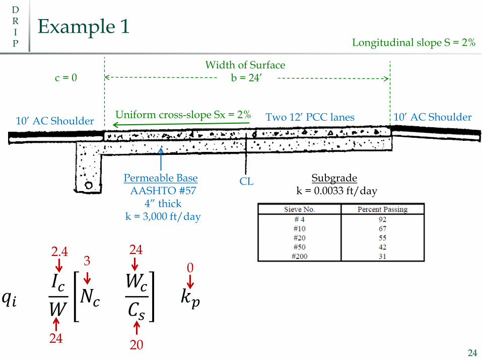
Example 1
24
10’ AC Shoulder 10’ AC ShoulderTwo 12’ PCC lanes
CL
Uniform cross-slope Sx = 2%
Longitudinal slope S = 2%
Permeable BaseAASHTO #57
4” thickk = 3,000 ft/day
Subgradek = 0.0033 ft/day
Width of Surface b = 24’
𝑞𝑞𝑖𝑖 =𝐼𝐼𝑐𝑐𝑊𝑊
𝑁𝑁𝑐𝑐 +𝑊𝑊𝑐𝑐𝐶𝐶𝑠𝑠
+ 𝑘𝑘𝑝𝑝
2.43
24
2024
0
c = 0

DRIP
Typical Open-Graded Bases and Filter Materials
Source: Moulton 25
Fine Sand
Medium Sand
Coarse Sand
Gravel
DRIP
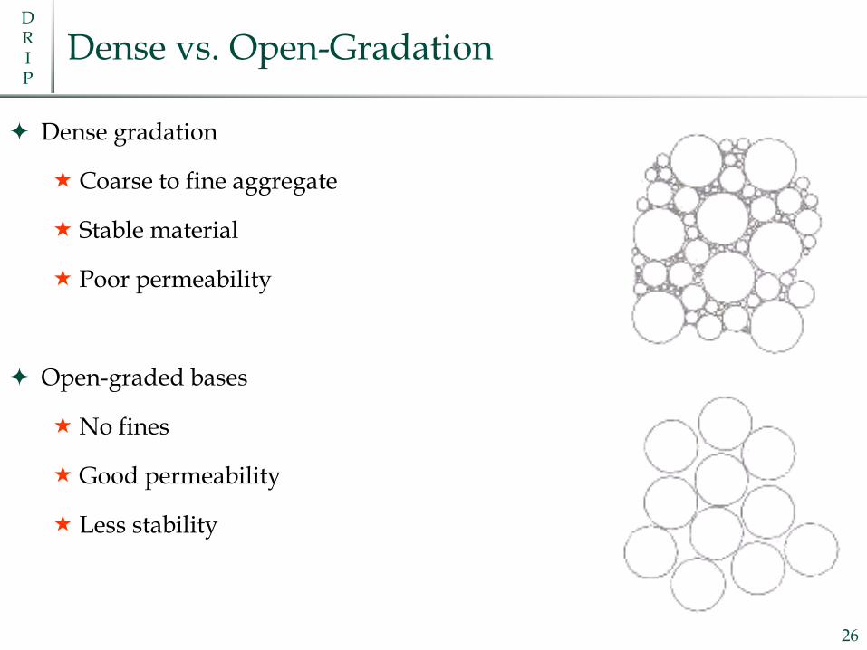
Dense vs. Open-Gradation
Dense gradation
Coarse to fine aggregate
Stable material
Poor permeability
Open-graded bases
No fines
Good permeability
Less stability
26
DRIP
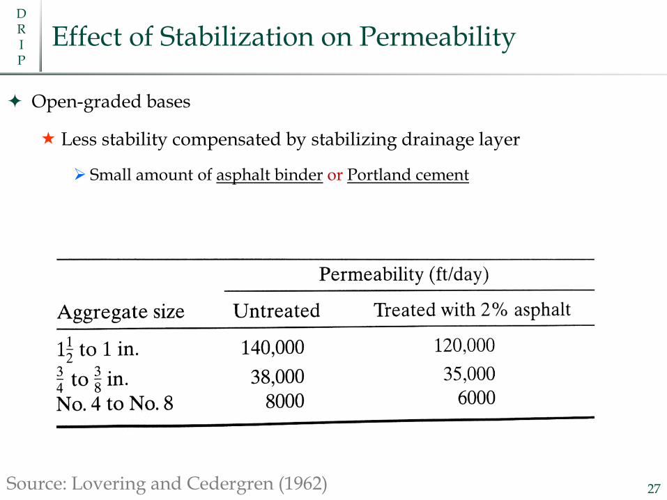
Effect of Stabilization on Permeability
Open-graded bases
Less stability compensated by stabilizing drainage layer
Small amount of asphalt binder or Portland cement
27Source: Lovering and Cedergren (1962)

DRIP
Example 2
Same input as example 1 with the following exceptions
Woven geotextile as separator
Hydraway geocomposite edgedrain
1. Calculate the time to drain of the permeable base
2. Design the geotextile separator layer
3. Calculate the outlet spacing for the geocomposite edgedrain
28
Nonwoven vs. Woven
DRIP
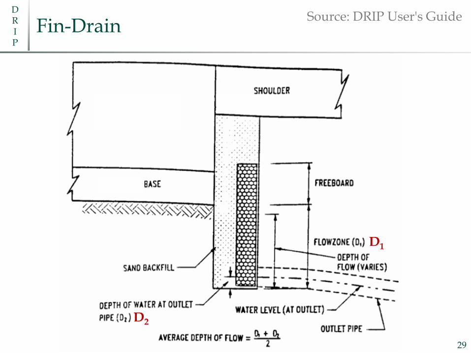
Fin-Drain
29
Source: DRIP User's Guide
D1
D2

DRIP
References
FHWA-TS-80-224 Highway Subdrainage Design; August 1980
Lyle K. Moulton, PhD, PE
https://www.fhwa.dot.gov/pavement/pubs/009633.pdf
Pavement Analysis and Design, 2nd Edition, Yang H. Huang, ISBN-13: 978-
0131424739/ISBN-10: 0131424734 – Chapter 8.
NCHRP, Guide for Mechanistic-Empirical Design; Part 3 - Design Analysis;
Chapter 1 – Drainage.
http://onlinepubs.trb.org/onlinepubs/archive/mepdg/Part3_Chapter1
_Subdrainage.pdf
FHWA-SA-92-008 Demonstration Project 87 Drainable Pavement Systems;
March 199230
Practical Design and Maintenance of Pavement Drainage SystemsCLARK GRAVES, PE, PG, PHD.ASSOCIATE DIRECTOR, KENTUCKY TRANSPORTATION CENTER
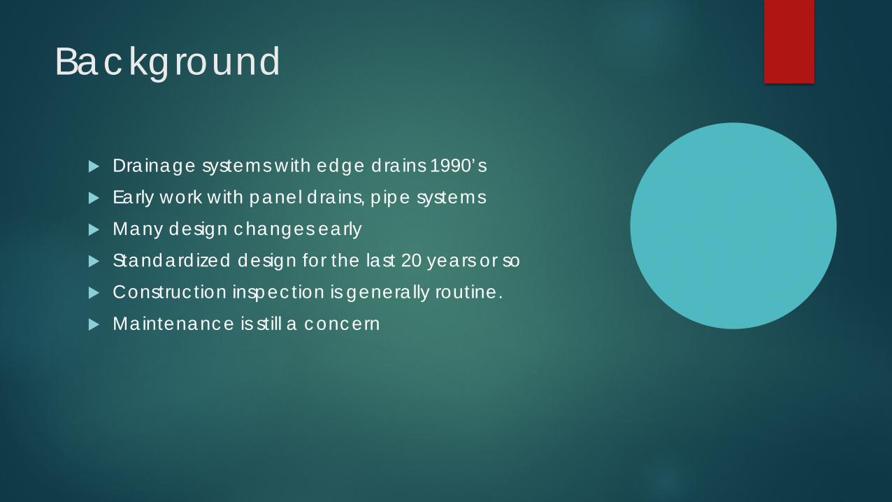
Background
Drainage systems with edge drains 1990’s Early work with panel drains, pipe systems Many design changes early Standardized design for the last 20 years or so Construction inspection is generally routine. Maintenance is still a concern

Type of Designs
New Construction Positive drainage layer
Daylighted
Positive pipe system with outlets
Closed System
Rehabilitation/Widening Permeability of new surfaces and layers
Adjacent pavement sections

Design Issues to Consider Different permeability between new and existing materials Drainage layer grade Depth of drains/outlets Is there an adequate flow path? We have standard design details, but not all designs are standard (DRIP)
0
100
200
300
400
surface leveling base
in / day
Pavement Layer
Permeability of Layers
Old
New

Case Study #1

Plans

Outlet Detail

Blocked Edge Drains
Blocked/Crushed
Open

Ground Penetrating Radar


0
50
100
150
200
250
300
350
surface leveling base
in / day
Pavement Layer
Permeability of Layers
Old
New

Case Study #2

Transverse Ground Penetrating Radar scans
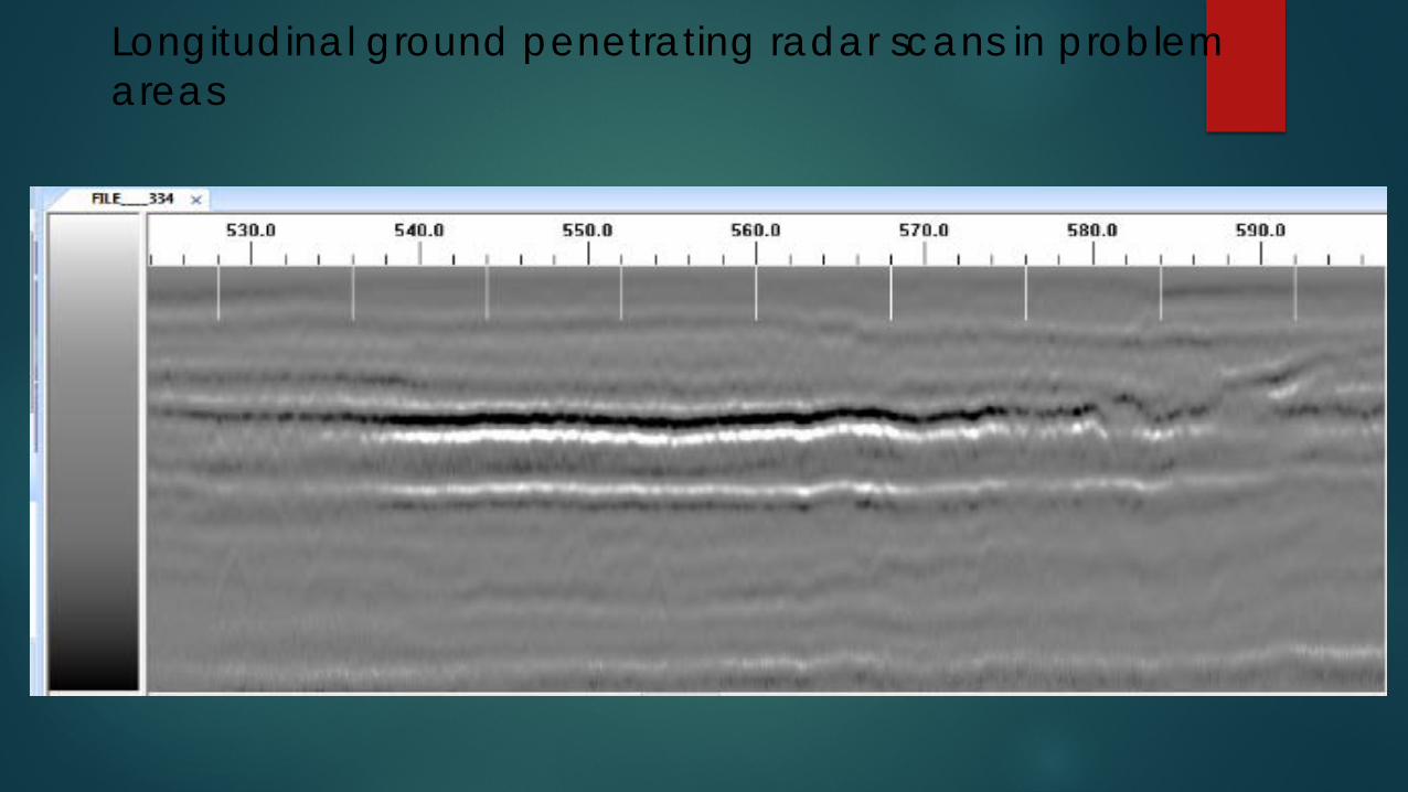
Longitudinal ground penetrating radar scans in problem areas
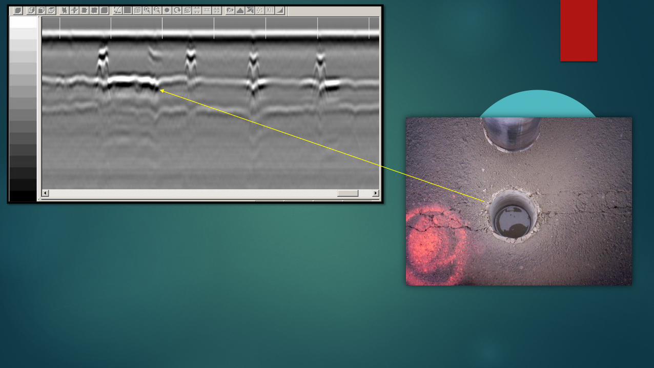

Transverse ground penetrating radar scans in problem areas
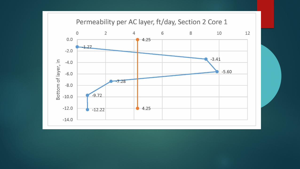
Elevation of edge drains
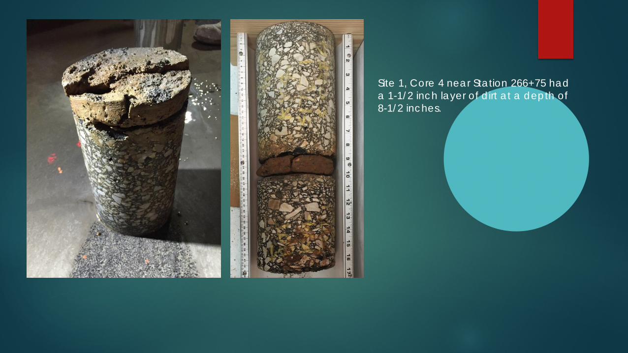
Site 1, Core 4 near Station 266+75 had a 1-1/2 inch layer of dirt at a depth of 8-1/2 inches.
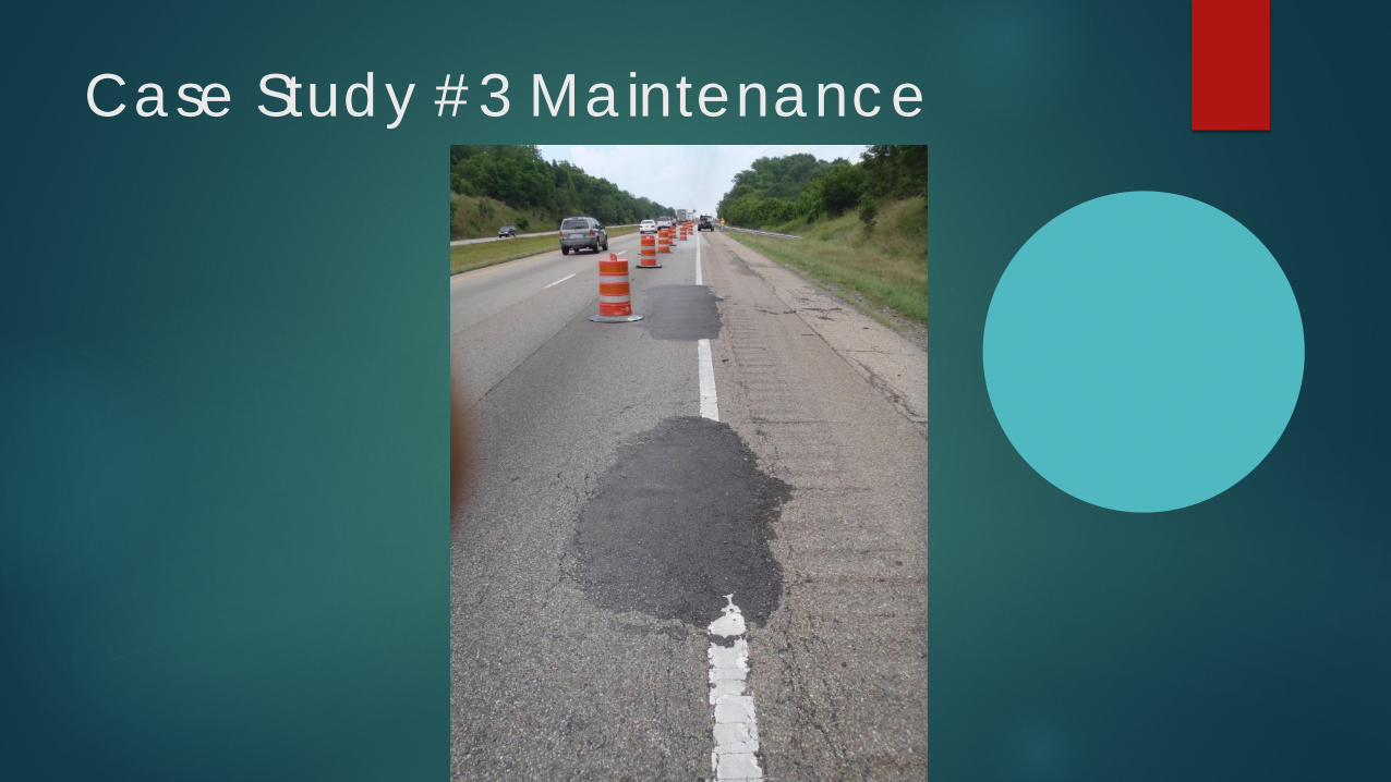
Case Study #3 Maintenance


ShoulderMainline Pavement
AC Pavement – 8”
Broken PCC – 10”
DGA – 6””
AC Pavement – 3”
DGA – 21””


Maintenance, Maintenance, Maintenance

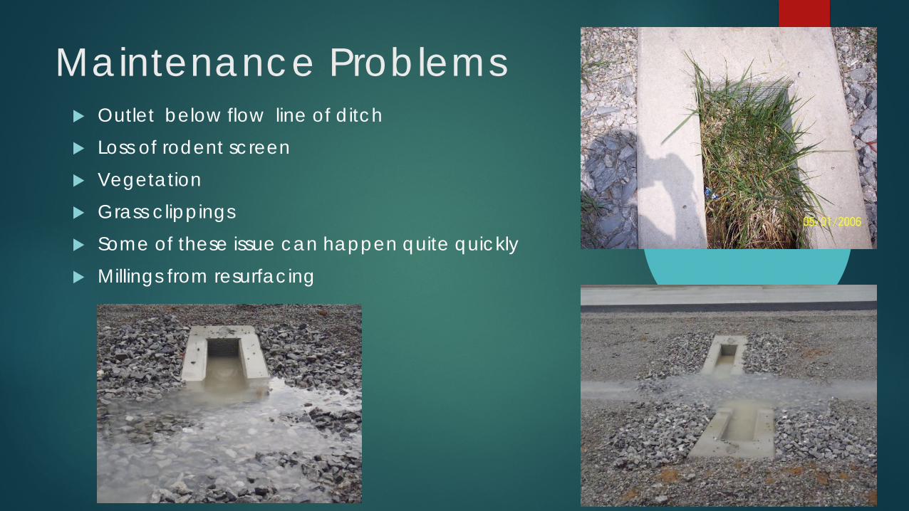
Maintenance Problems Outlet below flow line of ditch Loss of rodent screen Vegetation Grass clippings Some of these issue can happen quite quickly Millings from resurfacing

So When Should I Clean the Drains?
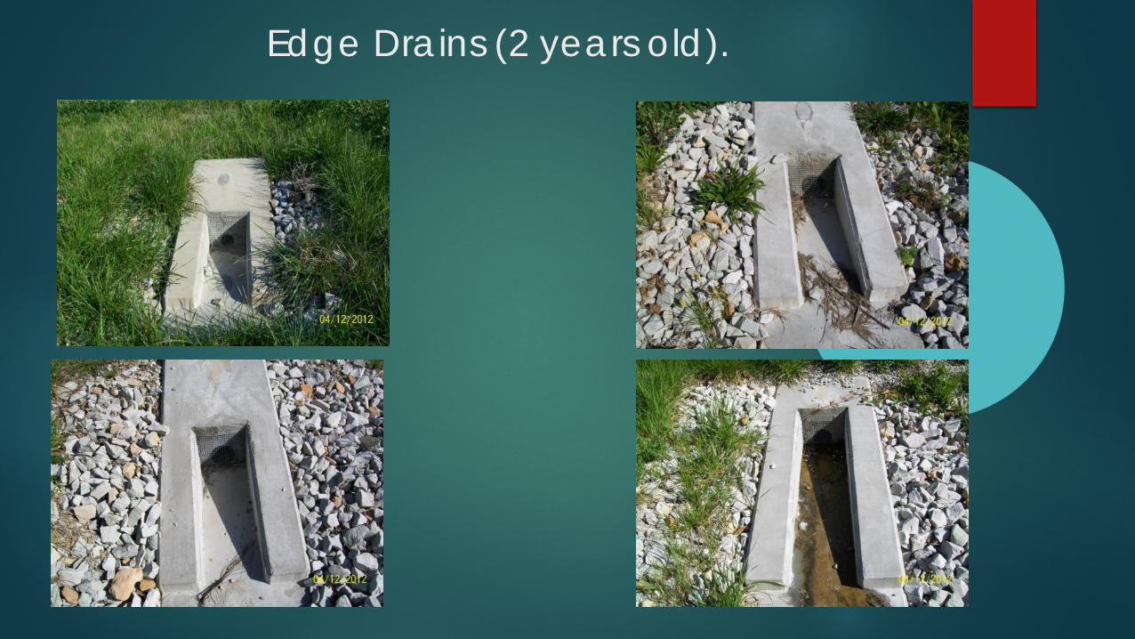
Edge Drains (2 years old).

Edge Drains (4 years old).

Edge Drains (4 years old).

Edge Drains (8 years old).
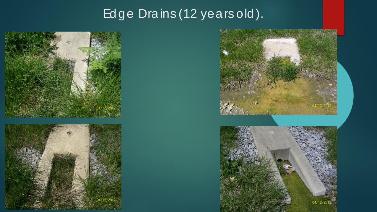
Edge Drains (12 years old).

2 Years Old 4 Years Old
8 Years Old 12 Years Old
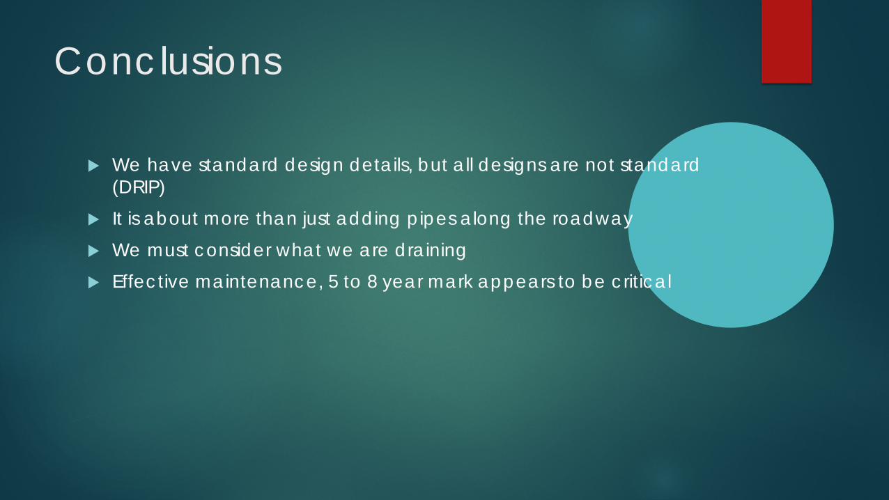
Conclusions
We have standard design details, but all designs are not standard (DRIP)
It is about more than just adding pipes along the roadway We must consider what we are draining Effective maintenance, 5 to 8 year mark appears to be critical

Thank You

Thank you for your time:
Questions?
• Please type your questions into your webinar control panel
• We will read your questions out loud, and answer as many as time allows
12

Today’s Speakers• Affan Habib, Virginia Department of
Transportation, [email protected]
• Mohamed Elfino, Virginia Department of Transportation (retired), [email protected]
• Gabriel Bazi, Lebanese American University, [email protected]
• Clark Graves, University of Kentucky, [email protected]

Get Involved with TRB• Getting involved is free!• Join a Standing Committee (http://bit.ly/2jYRrF6)• Become a Friend of a Committee
(http://bit.ly/TRBcommittees)– Networking opportunities– May provide a path to become a Standing Committee
member• Sponsoring Committees: AFS60, AFS70• For more information: www.mytrb.org
– Create your account– Update your profile
Receiving PDH credits
• Must register as an individual to receive credits (no group credits)
• Credits will be reported two to three business days after the webinar
• You will be able to retrieve your certificate from RCEP within one week of the webinar

Related Documents