COMPARISON FINE SPRAY NOZZLE FOR TWO PHASE FLOW WITHIN EXPERIMENTAL AND SIMULATION HAFIZ AIZAT BIN ALI A thesis submitted in fulfillment of the requirement for the award of the Master in Mechanical Engineering with Honour Faculty of Mechanical and Manufacturing Engineering Universiti Tun Hussein Onn Malaysia DISEMBER 2015

Welcome message from author
This document is posted to help you gain knowledge. Please leave a comment to let me know what you think about it! Share it to your friends and learn new things together.
Transcript
i
COMPARISON FINE SPRAY NOZZLE FOR TWO PHASE FLOW WITHIN
EXPERIMENTAL AND SIMULATION
HAFIZ AIZAT BIN ALI
A thesis submitted in
fulfillment of the requirement for the award of the
Master in Mechanical Engineering with Honour
Faculty of Mechanical and Manufacturing Engineering
Universiti Tun Hussein Onn Malaysia
DISEMBER 2015
iv
ABSTRACT
The conversion of bulk liquid into fine spray is very important nowadays in several
industrial process and has many application in agriculture, meteorology, and medicine.
So, the design to develop a fine spray nozzle was varies according to the application.
However, new development in fine spray nozzle have been achieved and implement
better than fine spray nozzle from Halton Group Asia Sdn. Bhd. Currently, the nozzle
from Halton Group used are produce in bulk liquid condition. The improvement that
make are the nozzle use low pressure with very fine water spray. This research was
focused on comparison for fine spray nozzle between simulation and experimental. The
observation focused on flow characteristic that produce by mist spray. Multiphase
nozzle were used with air and water as a medium . Six pressure inlet different are used
during the experiment. They are 0.5, 1.0, 1.5, 2.0, 2.5 and 3.0 bar. They are three type of
nozzles been tested Nozzle A, Nozzle B and Nozzle C. Nozzle A have eight air inlet slot
which give a better performance compared to other nozzles. The result evaluated from
this experiment are spray angle and the penetration. Nozzle A was sprayed with 3.0 bar
of water and air pressure. Mass flowrate for this pressure are 5.67x10⁻³
kgs-1
for water
and 2.698x10⁻⁴
kgs-1
for air. The angle of spray between experimental and simulation are
35.54° and 33.5° respectively. As a result, the percentage of similarity are 94.26%. High
speed camera are used to visualize the result an the software were used to simulate the
fine spray ANSYS FLUENT version 14.5. By using fine spray technology, it can trap
dust and small particle in air inside kitchen hood more effective and can consume less
water.
v
ABSTRAK
Pada masa sekarang, proses penukaran cecair kepada semburan halus amat penting di
dalam beberapa proses industri dan aplikasinya banyak di dalam aplikasi pertanian,
meteorologi dan perubatan. Maka, reka bentuk nozzle semburan halus berbeza mengikut
aplikasinya. Walau bagaimanapun, sebuah nozzle semburan halus telah dibina semula
bagi menambah baik nozzle milik Halton Group Asia Sdn Bhd. Nozzle milik Halton
hanya menghasilkan semburan kasar. Penambah baikkan yang dibuat adalah nozzle
tersebut menggunakan tekanan udara yang rendah untuk menghasilkan semburan halus.
Fokus untuk kajian ini adalah bagi membandingkan nozzle semburan halus di antara
eksperimen dan simulasi. Nozzle ini merupakan jenis multiphase di mana air dan udara
digunakan. Enam jenis tekanan telah digunakan di dalam eksperimen ini. Ia adalah 0.5,
1.0, 1.5, 2.0, 2.5 dan 3.0 bar. Terdapat tiga jenis nozzle telah dikaji iaitu Nozzle A,
Nozzle B, dan Nozzle C dan Nozzle A yang mempunyai lapan slot masukkan udara
memberi prestasi yang lebih baik dari nozzle yang lain. Keputusan yang telah diambil
adalah sudut semburan dan penembusan. Nozzle A telah menggunakan tekanan udara
dan air sebanyak 3.0 bar. Kadar alir jisim air yang dihasilkan adalah 5.67x10⁻³
kgs-1
dan
bagi udara pula adalah 2.698x10⁻⁴
kgs-1
. Sudut semburan di antara eksperimen dan
simulasi adalah 35.54° dan 33.5°. Hasilnya, peratusan persamaan adalah sebanyak
94.26%. Kamera halaju tinggi telah diguna untuk mendapatkan imej semburan dan
perisian yang digunakan untuk simulasi adalah ANSYS FLUENT versi 14.5.
Penggunaan teknologi semburan halus ini dapat memerangkap habuk dan partikel halus
udara di dalam hud dapur dengan lebih berkesan dan penggunaan air untuk bekalan
nozzle semburan halus juga dapat dijimatkan.
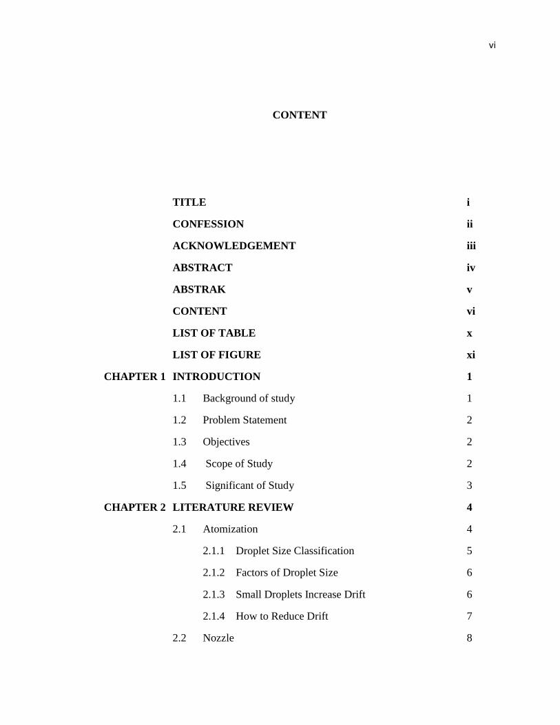
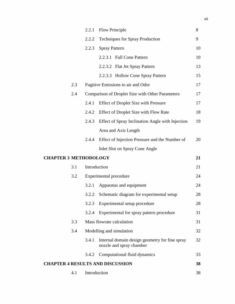
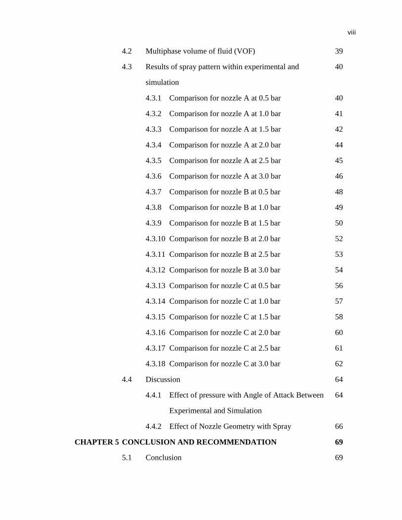
vi
CONTENT
TITLE i
CONFESSION ii
ACKNOWLEDGEMENT iii
ABSTRACT iv
ABSTRAK v
CONTENT vi
LIST OF TABLE x
LIST OF FIGURE xi
CHAPTER 1 INTRODUCTION 1
1.1 Background of study 1
1.2 Problem Statement 2
1.3 Objectives 2
1.4 Scope of Study 2
1.5 Significant of Study 3
CHAPTER 2 LITERATURE REVIEW 4
2.1 Atomization 4
2.1.1 Droplet Size Classification 5
2.1.2 Factors of Droplet Size 6
2.1.3 Small Droplets Increase Drift 6
2.1.4 How to Reduce Drift 7
2.2 Nozzle 8
vii
2.2.1 Flow Principle 8
2.2.2 Techniques for Spray Production 9
2.2.3 Spray Pattern 10
2.2.3.1 Full Cone Pattern 10
2.2.3.2 Flat Jet Spray Pattern 13
2.2.3.3 Hollow Cone Spray Pattern 15
2.3 Fugitive Emissions to air and Odor 17
2.4 Comparison of Droplet Size with Other Parameters 17
2.4.1 Effect of Droplet Size with Pressure 17
2.4.2 Effect of Droplet Size with Flow Rate 18
2.4.3 Effect of Spray Inclination Angle with Injection 19
Area and Axis Length
2.4.4 Effect of Injection Pressure and the Number of 20
Inlet Slot on Spray Cone Angle
CHAPTER 3 METHODOLOGY 21
3.1 Introduction 21
3.2 Experimental procedure 24
3.2.1 Apparatus and equipment 24
3.2.2 Schematic diagram for experimental setup 28
3.2.3 Experimental setup procedure 28
3.2.4 Experimental for spray pattern procedure 31
3.3 Mass flowrate calculation 31
3.4 Modelling and simulation 32
3.4.1 Internal domain design geometry for fine spray 32
nozzle and spray chamber
3.4.2 Computational fluid dynamics 33
CHAPTER 4 RESULTS AND DISCUSSION 38
4.1 Introduction 38
viii
4.2 Multiphase volume of fluid (VOF) 39
4.3 Results of spray pattern within experimental and 40
simulation
4.3.1 Comparison for nozzle A at 0.5 bar 40
4.3.2 Comparison for nozzle A at 1.0 bar 41
4.3.3 Comparison for nozzle A at 1.5 bar 42
4.3.4 Comparison for nozzle A at 2.0 bar 44
4.3.5 Comparison for nozzle A at 2.5 bar 45
4.3.6 Comparison for nozzle A at 3.0 bar 46
4.3.7 Comparison for nozzle B at 0.5 bar 48
4.3.8 Comparison for nozzle B at 1.0 bar 49
4.3.9 Comparison for nozzle B at 1.5 bar 50
4.3.10 Comparison for nozzle B at 2.0 bar 52
4.3.11 Comparison for nozzle B at 2.5 bar 53
4.3.12 Comparison for nozzle B at 3.0 bar 54
4.3.13 Comparison for nozzle C at 0.5 bar 56
4.3.14 Comparison for nozzle C at 1.0 bar 57
4.3.15 Comparison for nozzle C at 1.5 bar 58
4.3.16 Comparison for nozzle C at 2.0 bar 60
4.3.17 Comparison for nozzle C at 2.5 bar 61
4.3.18 Comparison for nozzle C at 3.0 bar 62
4.4 Discussion 64
4.4.1 Effect of pressure with Angle of Attack Between 64
Experimental and Simulation
4.4.2 Effect of Nozzle Geometry with Spray 66
CHAPTER 5 CONCLUSION AND RECOMMENDATION 69
5.1 Conclusion 69

ix
5.2 Recommendation 70
REFERENCES 71
APPENDIX 74
x
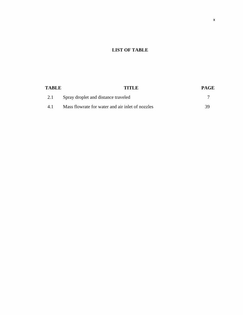
LIST OF TABLE
TABLE TITLE PAGE
2.1 Spray droplet and distance traveled 7
4.1 Mass flowrate for water and air inlet of nozzles 39
xi
LIST OF FIGURE
FIGURE TITLE PAGE
2.1 Atomization 4
2.2 Categories of spray droplet size in micron 5
2.3 Flow principle for nozzle 9
2.4 Standard full cone 11
2.5 Spiral full cone (deflection nozzle) 12
2.6 Multiple full cone (turbulence nozzle, air atomizer) 13
2.7 In flat jet (pressure nozzle) 14
2.8 Spoon flat jet (deflection nozzle) 15
2.9 Hollow cone (turbulence nozzle) 16
2.10 Hollow cone (deflection nozzle) 16
2.11 Relationship between droplet size and pressure of nozzles 17
2.12 Drop size and spray flow rates for exit orifice diameters of 0.2 and 18
0.3mm at two supply pressures and with variation of spill orifice
diameter
2.13 The relation of spray inclination angle with axis length of spray 19
injection zone and spray injection area
2.14 Effect of injection pressure and the number of inlet slot on spray 20
cone angle
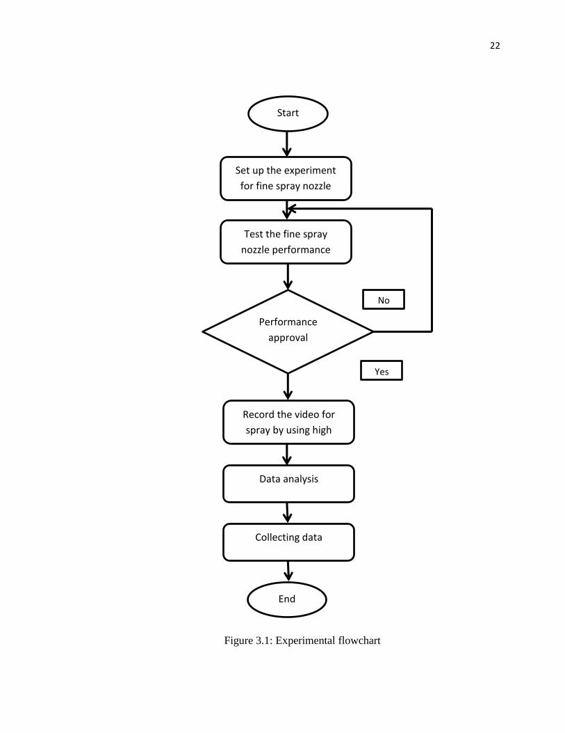
3.1 Experimental flowchart 22
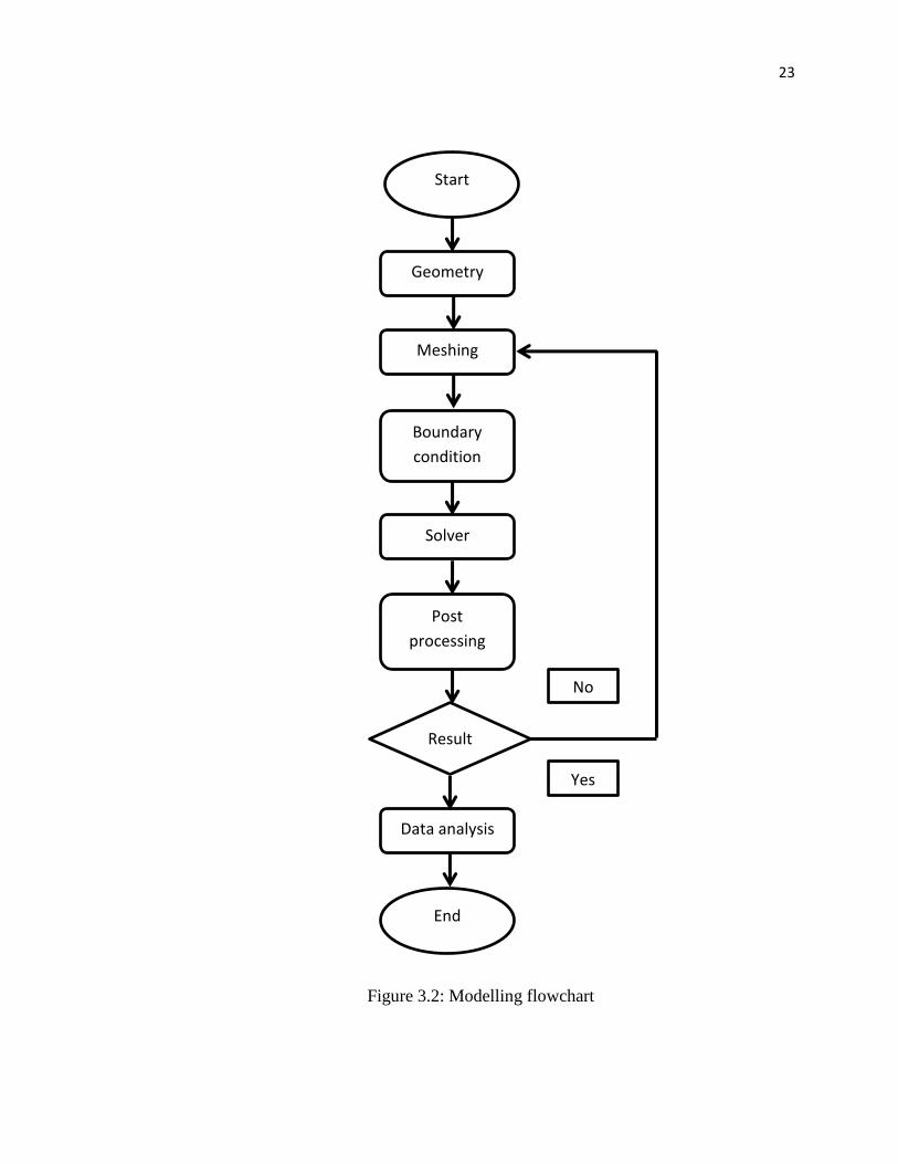
3.2 Modelling flowchart 23

xii
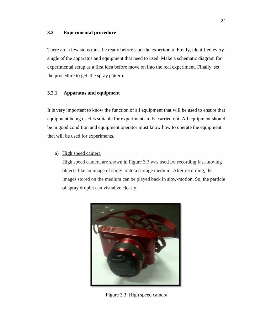
3.3 High speed camera 24
3.4 Air compressor 25
3.5 Holder 25
3.6 Water tank pressure 26
3.7 Water flowrate 26
3.8 Pressure gauge 27
3.9 Schematic diagram of experimental set-up 28
3.10 Grid background 29
3.11 Water and air tube setup 29
3.12 Location for nozzle high speed camera 30
3.13 Camera focusing on nozzle and grid background 30
3.14 Design for nozzle A 33
3.15 The flow of components in ANSYS Fluent 34
3.16 Internal domain for fine spray nozzle 35
3.17 Meshing 36
4.1(a) Experimental result for Nozzle A at 0.5 bar 40
4.1(b) Simulation result for Nozzle A at 0.5 bar 41
4.1(c) Spray for nozzle A at 0.5 bar 41
4.2(a) Experimental result for Nozzle A at 1.0 bar 42
4.2(b) Simulation result for Nozzle A at 1.0 bar 42
4.2(c) Spray for nozzle A at 1.0 bar 42
4.3(a) Experimental result for Nozzle A at 1.5 bar 43
4.3(b) Simulation result for Nozzle A at 1.5 bar 43
4.3(c) Spray for nozzle A at 1.5 bar 43
4.4(a) Experimental result for Nozzle A at 2.0 bar 44
4.4(b) Simulation result for Nozzle A at 2.0 bar 44
4.4(c) Spray for nozzle A at 2.0 bar 45
xiii
4.5(a) Experimental result for Nozzle A at 2.5 bar 46
4.5(b) Simulation result for Nozzle A at 2.5 bar 46
4.5(c) Spray for nozzle A at 2.5 bar 46
4.6(a) Experimental result for Nozzle A at 3.0 bar 47
4.6(b) Simulation result for Nozzle A at 3.0 bar 47
4.6(c) Spray for nozzle A at 3.0 bar 47
4.7(a) Experimental result for Nozzle B at 0.5 bar 48
4.7(b) Simulation result for Nozzle B at 0.5 bar 48
4.7(c) Spray for nozzle B at 0.5 bar 48
4.8(a) Experimental result for Nozzle B at 1.0 bar 50
4.8(b) Simulation result for Nozzle B at 1.0 bar 50
4.8(c) Spray for nozzle B at 1.0 bar 50
4.9(a) Experimental result for Nozzle B at 1.5 bar 51
4.9(b) Simulation result for Nozzle B at 1.5 bar 51
4.9(c) Spray for nozzle B at 1.5 bar 51
4.10(a) Experimental result for Nozzle B at 2.0 bar 52
4.10(b) Simulation result for Nozzle B at 2.0 bar 52
4.10(c) Spray for nozzle B at 2.0 bar 53
4.11(a) Experimental result for Nozzle B at 2.5 bar 54
4.11(b) Simulation result for Nozzle B at 2.5 bar 54
4.11(c) Spray for nozzle B at 2.5 bar 54
4.12(a) Experimental result for Nozzle B at 3.0 bar 55
4.12(b) Simulation result for Nozzle B at 3.0 bar 55
4.12(c) Spray for nozzle B at 3.0 bar 55
4.13(a) Experimental result for Nozzle C at 0.5 bar 56
4.13(b) Simulation result for Nozzle C at 0.5 bar 56
4.13(c) Spray for Nozzle C at 0.5 bar 57
xiv
4.14(a) Experimental result for Nozzle C at 1.0 bar 58
4.14(b) Simulation result for Nozzle C at 1.0 bar 58
4.14(c) Spray for Nozzle C at 1.0 bar 58
4.15(a) Experimental result for Nozzle C at 1.5 bar 59
4.15(b) Simulation result for Nozzle C at 1.5 bar 59
4.15(c) Spray for Nozzle C at 1.5 bar 59
4.16(a) Experimental result for Nozzle C at 2.0 bar 60
4.16(b) Simulation result for Nozzle C at 2.0 bar 60
4.16(c) Spray for Nozzle C at 2.0 bar 61
4.17(a) Experimental result for Nozzle C at 2.5 bar 62
4.17(b) Simulation result for Nozzle C at 2.5 bar 62
4.17(c) Spray for Nozzle C at 2.5 bar 62
4.18(a) Experimental result for Nozzle C at 3.0 bar 63
4.18(b) Simulation result for Nozzle C at 3.0 bar 63
4.18(c) Spray for Nozzle C at 3.0 bar 63
4.19 Graph pressure versus angle of attack for Nozzle A, Nozzle B, and 65
Nozzle C
4.20 Angle of attack at pressure 3.0 bar for (a) Nozzle A 35.54°, (b) Nozzle 67
B 32.24° and (c) Nozzle C 30.62°
4.21 Velocity vector at 3.0 bar for (a) Nozzle A, (b) Nozzle B 68
and (c) Nozzle C
1
CHAPTER 1
INTRODUCTION
1.1 Background of study
The transformation of bulk liquid into sprays and other physical dispersions of small
particles in a gaseous atmosphere is importance in several industrial processes and has
many other application in agriculture, meteorology, and medicine. Numerous spray
devices have been developed, and they are generally designated as atomizers or nozzles.
Many experimental and theoretical studies about the atomization method have been
carried out since the atomizer was used in the diesel engine in 1892 [1].
The importance of drop size for many combustion and industrial processes that
utilize liquid sprays is attested to by the proliferation of techniques available for drop
size measurement. No single technique is completely satisfactory but each technique has
its own advantages and drawbacks, depending on the application. Direct methods
include those in which individual drops are collected on slide for subsequent
measurement and counting or in which droplets are frozen and sized as solid particles.
With the impaction methods the drop are sorted on the basis of inertial differences.
Depending on its size, a droplet may impact or fail to impact on a solid surface or may
follow a different trajectory. This allows all the drops in a spray to be sorted into
different size and categories.
The conversion of bulk liquid into fine spray is very important nowadays in
several industrial process and has many application in agriculture, meteorology, and
medicine. So, the design to develop a fine spray nozzle was varies according to the
application. However, new development in fine spray nozzle have been achieved and
2
implement better than fine spray nozzle from Halton Group Asia Sdn. Bhd. Currently,
the nozzle from Halton Group used are produce in bulk liquid condition. The
improvement that make are the nozzle use low pressure with very fine water spray. This
research was focused on comparison for fine spray nozzle between simulation and
experimental.
1.2 Problem Statement
Currently, majority of the users using the spray nozzle that already sold in the market.
The spray nozzle that sold in the market has a weakness such as need high pressure and
more water consumption. Using high pressure mean consume more energy usage, using
more volume of water mean the droplet size of water still large and the nozzle need
modification.
Thus we need is to produce a better type of nozzle. We need to produce the
nozzle that use low pressure with very fine water spray. Nowadays, the industrial
produce many types of spray nozzle for example air assist, air blast, rotary and pressure
atomizer. This types of nozzle have different shapes and various form of pressure
atomizer but still using a high pressure and a larger droplet size. Further research must
be done in this field to improve the spray nozzle.
1.3 Objectives
1. To observe flow characteristic that produce by mist spray.
2. Analysis flow visualization inside the nozzle.
3. Validation on mist spray between the experiment and simulation.
1.4 Scope of Study
1. Experiment have been conducted with water and air pressure 0.5, 1.0, 1.5, 2.0,
2.5, dan 3.0 bar .
2. Water were used as liquid agent.
3
3. Simulation analysis using ANSYS software.
4. Material for the nozzle is stainless steel.
5. Three different nozzle will be tested which have 4, 8 and 6 air flow holes.
6. The fine spray nozzle was followed the act of treatment of aerosol Section 2.2.4
and 2.2.6 of SGN 5.06
1.5 Significant of Study
1. Many new technologies that relate with fine spray will be developed.
2. Low pressure to produce fine spray will consume less energy require by the
system thus it reduce the cost [3].
4
CHAPTER 2
LITERATURE REVIEW
2.1 Atomization
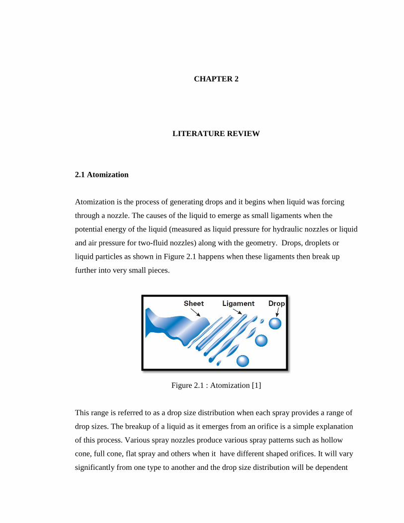
Atomization is the process of generating drops and it begins when liquid was forcing
through a nozzle. The causes of the liquid to emerge as small ligaments when the
potential energy of the liquid (measured as liquid pressure for hydraulic nozzles or liquid
and air pressure for two-fluid nozzles) along with the geometry. Drops, droplets or
liquid particles as shown in Figure 2.1 happens when these ligaments then break up
further into very small pieces.
Figure 2.1 : Atomization [1]
This range is referred to as a drop size distribution when each spray provides a range of
drop sizes. The breakup of a liquid as it emerges from an orifice is a simple explanation
of this process. Various spray nozzles produce various spray patterns such as hollow
cone, full cone, flat spray and others when it have different shaped orifices. It will vary
significantly from one type to another and the drop size distribution will be dependent
5
on the nozzle type. The drop size also was affected to the factors such as the liquid
properties, nozzle capacity, spraying pressure and spray angle.
During the last decade, the importance of drop size information has increased
considerably. Information for effective use was important to the many spray applications
such as evaporative cooling, gas conditioning, fire suppression, spray drying and
agricultural spraying [1].
2.1.1 Droplet Size Classification
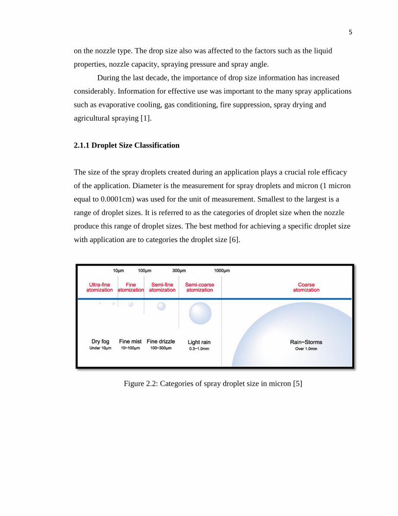
The size of the spray droplets created during an application plays a crucial role efficacy
of the application. Diameter is the measurement for spray droplets and micron (1 micron
equal to 0.0001cm) was used for the unit of measurement. Smallest to the largest is a
range of droplet sizes. It is referred to as the categories of droplet size when the nozzle
produce this range of droplet sizes. The best method for achieving a specific droplet size
with application are to categories the droplet size [6].
Figure 2.2: Categories of spray droplet size in micron [5]
6
2.1.2 Factors of Droplet Size
According to the following factors, the size of droplets sprayed from a spray nozzle was
varies [9].
1. Types of nozzles: Full cone type nozzles produce smaller droplets than flat spray
types even the pressure and flowrate inlet are the same. The former that produced
the diameter of droplets can sometimes be several times smaller than those
produced by the latter.
2. Pressure: The smaller droplets was appeared when pressure increase at inlet. For
example, a spray nozzle that produces droplets of 1,000 microns at 1Mpa will
produce much smaller droplets (of several tens of microns) if pressure is
increased to 10MPa.
3. Flow rate: The smaller droplets was appeared when the value flow rate are
reduced. For example, a spray nozzle that delivers very small volume of liquid,
such as 10ml/min, produces droplets of several tens of microns. A spray nozzle
that delivers high volumes of liquid, such as 1,000 l/min, produces (at the same
pressure) droplets of several thousands of microns. When flow rate is increased
or decreased droplet diameter can, therefore, be several hundred times greater or
smaller.
4. Fluid: Two mixed fluids (including gas) sprayed by a nozzle can produce far
finer droplets than a nozzle that sprays only liquid. Furthermore, droplet size can
be reduced if the gas flow rate of the former spray nozzle is increased. Normal
nozzles that spray two mixed fluids normally produced the mean droplet
diameter several tens of microns.
2.1.3 Small Droplets Increase Drift.
The potential for evaporation, drift, canopy penetration, and deposition of the spray
particles need to be considered even atomizing is the spray solution into very small
droplets that increased the coverage possible. Drift is the greater risk to the smaller
7
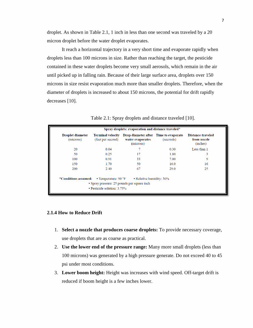
droplet. As shown in Table 2.1, 1 inch in less than one second was traveled by a 20
micron droplet before the water droplet evaporates.
It reach a horizontal trajectory in a very short time and evaporate rapidly when
droplets less than 100 microns in size. Rather than reaching the target, the pesticide
contained in these water droplets become very small aerosols, which remain in the air
until picked up in falling rain. Because of their large surface area, droplets over 150
microns in size resist evaporation much more than smaller droplets. Therefore, when the
diameter of droplets is increased to about 150 microns, the potential for drift rapidly
decreases [10].
Table 2.1: Spray droplets and distance traveled [10].
2.1.4 How to Reduce Drift
1. Select a nozzle that produces coarse droplets: To provide necessary coverage,
use droplets that are as coarse as practical.
2. Use the lower end of the pressure range: Many more small droplets (less than
100 microns) was generated by a high pressure generate. Do not exceed 40 to 45
psi under most conditions.
3. Lower boom height: Height was increases with wind speed. Off-target drift is
reduced if boom height is a few inches lower.
8
4. Increase nozzle size: Drift was reduced by a larger capacity of nozzles. Increase
to nozzles that put out 15 to 20 GPA if the nozzles that output 10 to 15 gallons
per acre (GPA).
5. Spray when wind speeds are less than 10 m.p.h.: The increases of wind will
make a spray move off-target.
6. Spray when wind is moving away from sensitive crops: If sensitive plants are
downwind, leave a buffer zone. When the wind changes direction, spray the
buffer zone.
7. Do not spray when the air is very calm: Spray can move slowly downwind
during calm air, or an inversion and reduces air mixing. Early morning or near
bodies of water generally inversions generally occur.
8. Use a drift control additive when needed: Average droplet size produced by
nozzles increased when using the drift control additives.
2.2 Nozzle
A device which makes use of the pressure energy of a liquid to increase its speed
through an orifice and break it into drops called as a nozzle. Most important physical
aspects firstly an overview of the of the internal flow through a nozzle will be given. The
definition of at least two phases are requirement for the multiphase simulation of nozzle
flow which is liquid and vapourization, and eventually air for the boundary conditions in
the atmosphere [4].
2.2.1 Flow Principle
Tight control of drop size and spray coverage was controlled by a high efficiency
nozzles. To achieve this very small drop size, a multi-stage atomization process must be
used as shown in Figure 2.3 [3].
9
1. Stage one : Primary Fluid Breakup
Behind the air guide, air and liquid combine. Primary atomization of the liquid stream
will be provide when the pressure drop across the air guide orifice.
2. Stage two : Secondary Fluid Breakup
Additional mechanical breakup happen when focused stream impacts the target bolt.
3. Stage three : Final Mixing
Air cap acts as a final mixing chamber. An additional, pressure drop provides the final
atomization after a liquid crosses multiple orifices.
Figure 2.3: Flow principle for nozzle [3]
2.2.2 Techniques for Spray Production
To produce a spray, many different techniques can be used. The following nozzle types
can be used in industrial applications to generate a liquid spray based on the different
techniques [8].
1. Pressure nozzles: This nozzle is the simplest type, where the liquid to be
sprayed is fed under pressure, an orifice is opened into a chamber. Spray pattern,
flow rate and spray angle produced through the orifice by a spray with depending
upon the orifice edge profile and the design of the inside pressure chamber.
2. Turbulence nozzles: The liquid moving towards the chamber preceding the
orifice is given a rotational speed component in these nozzles, so as to open up in
10
a conical shape as soon as it leaves the orifice edge because of centrifugal force.
The drops produced can be confined to the cone outer surface (hollow cone
spray) or be evenly distributed to fill the entire volume of the cone (full cone
spray based on the nozzle design and the technique used to generate the
rotational speed.
3. Impact nozzle: An impact of the liquid jet onto a properly designed surface will
produced if the desired spray shape is obtained. After leaving the nozzle edge,
the liquid jet is subsequently changed into a fluid lamina and then broken into
drops with the desired spray pattern.
4. Air assisted atomizers: By means of air assisted atomizers, working upon
various different principles, fine and very fine sprays can be obtained.
2.2.3 Spray Pattern
The shape of their spray pattern is the most basic distinguishing characteristic and there
are many types of spray nozzles. Determining the type of spray pattern required for a
particular operation is the typically beginning of nozzle selections [9].
2.2.3.1 Full Cone Pattern
The droplets are distributed into a volume which is limited by a cone in a full cone
spray, having its origin point at the nozzle orifice. In a large variety of industrial
processes this such spray pattern is commonly used, since it is the one which allows to
distribute in an even way the water flow onto a surface. To evenly spray cooling liquid
on a still surface, the full cone spray pattern is therefore useful, as a typical example.
Distribute liquid droplets within a certain volume is an another typical use, like for
example evenly distributing water droplets in the inside volume of a cooling tower
because of the wide number of processes performed by means of full cone nozzles.
Where the full cone spray pattern, or a pattern similar to a full cone one, is obtained by
different techniques, the original shape has evolved into a range of specialized types.
11
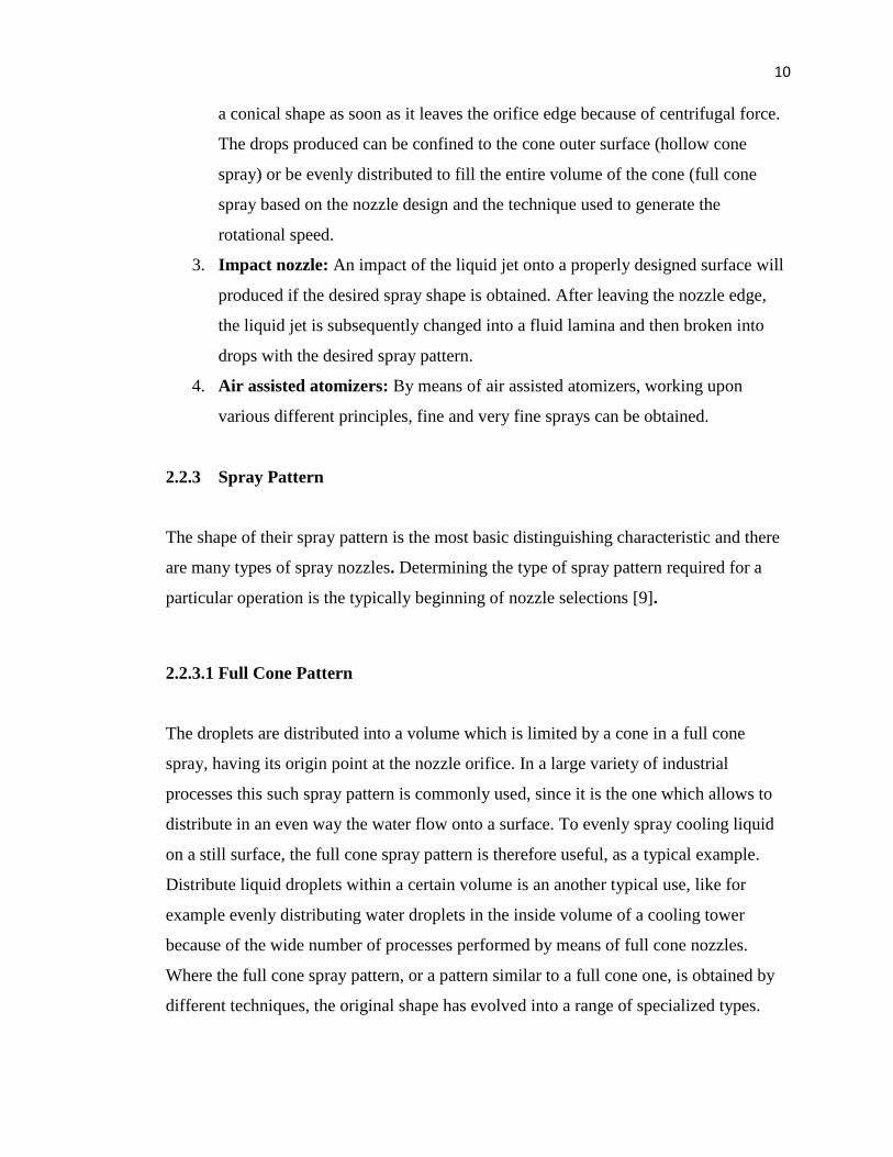
1. Standard full cone (turbulence nozzle)
Shaped vane placed at the nozzle inlet usually used by the nozzle as shown in
Figure 2.4, to give a rotational speed to the fluid flowing through the nozzle
because of the rotational speed of the fluid, water exiting the nozzle orifice is
subjected to centrifugal force and opens up in the shape of a full cone. The extent
of the angle of the cone is a function of both exit speed (created from the inlet
pressure) and the internal design of the nozzle. It can vary in practice from 15° to
120°. These nozzles can be also produced as square full cone nozzles, where the
square shape of the pyramidal spray is obtained by a special design of the outlet
orifice. Two important details have to be noted from the system designer when
using these type of nozzles is:
a) The spray angle is measured on the side of the square section
b) The square section of the spray rotates within the distance from the nozzle orifice
to the target area.
Figure 2.4: Standard full cone (turbulence nozzle) [9]
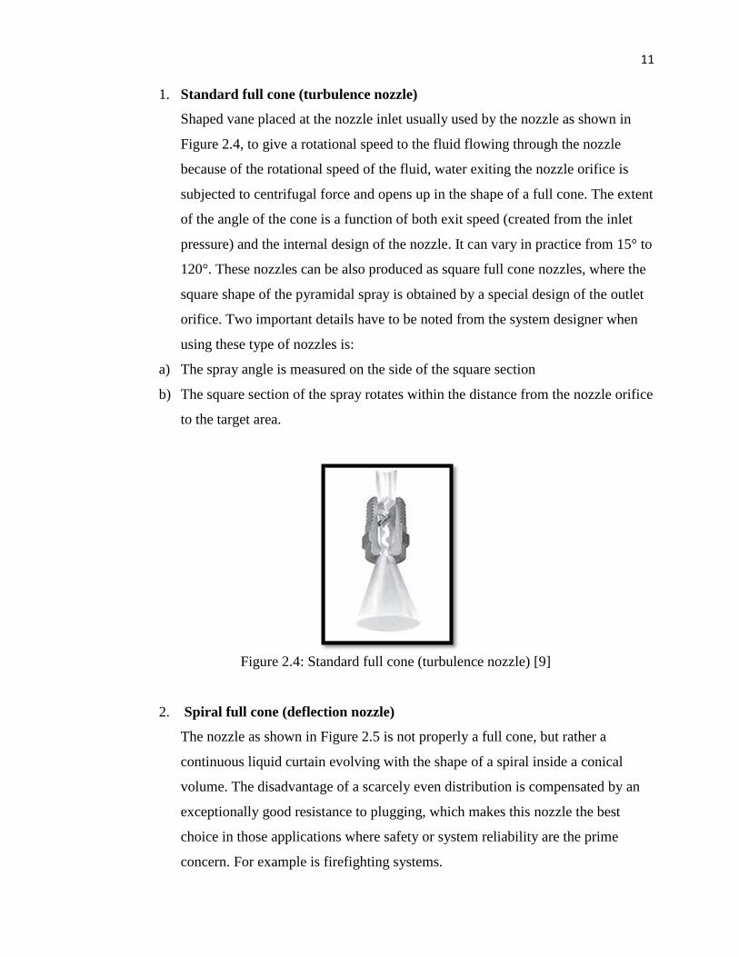
2. Spiral full cone (deflection nozzle)
The nozzle as shown in Figure 2.5 is not properly a full cone, but rather a
continuous liquid curtain evolving with the shape of a spiral inside a conical
volume. The disadvantage of a scarcely even distribution is compensated by an
exceptionally good resistance to plugging, which makes this nozzle the best
choice in those applications where safety or system reliability are the prime
concern. For example is firefighting systems.
12
Figure 2.5: Spiral full cone (deflection nozzle) [9]
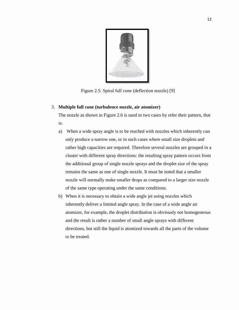
3. Multiple full cone (turbulence nozzle, air atomizer)
The nozzle as shown in Figure 2.6 is used in two cases by refer their pattern, that
is:
a) When a wide spray angle is to be reached with nozzles which inherently can
only produce a narrow one, or in such cases where small size droplets and
rather high capacities are required. Therefore several nozzles are grouped in a
cluster with different spray directions: the resulting spray pattern occurs from
the additional group of single nozzle sprays and the droplet size of the spray
remains the same as one of single nozzle. It must be noted that a smaller
nozzle will normally make smaller drops as compared to a larger size nozzle
of the same type operating under the same conditions.
b) When it is necessary to obtain a wide angle jet using nozzles which
inherently deliver a limited angle spray. In the case of a wide angle air
atomizer, for example, the droplet distribution is obviously not homogeneous
and the result is rather a number of small angle sprays with different
directions, but still the liquid is atomized towards all the parts of the volume
to be treated.
13
Figure 2.6: Multiple full cone (turbulence nozzle, air atomizer) [9]
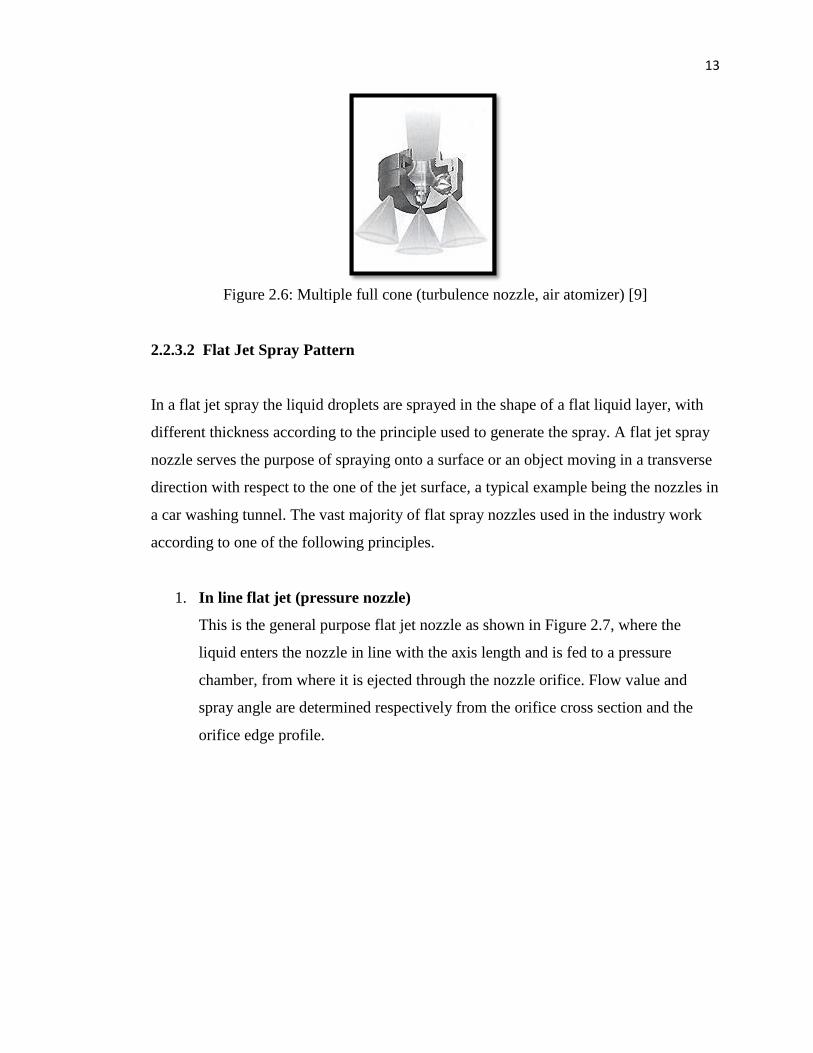
2.2.3.2 Flat Jet Spray Pattern
In a flat jet spray the liquid droplets are sprayed in the shape of a flat liquid layer, with
different thickness according to the principle used to generate the spray. A flat jet spray
nozzle serves the purpose of spraying onto a surface or an object moving in a transverse
direction with respect to the one of the jet surface, a typical example being the nozzles in
a car washing tunnel. The vast majority of flat spray nozzles used in the industry work
according to one of the following principles.
1. In line flat jet (pressure nozzle)
This is the general purpose flat jet nozzle as shown in Figure 2.7, where the
liquid enters the nozzle in line with the axis length and is fed to a pressure
chamber, from where it is ejected through the nozzle orifice. Flow value and
spray angle are determined respectively from the orifice cross section and the
orifice edge profile.
14
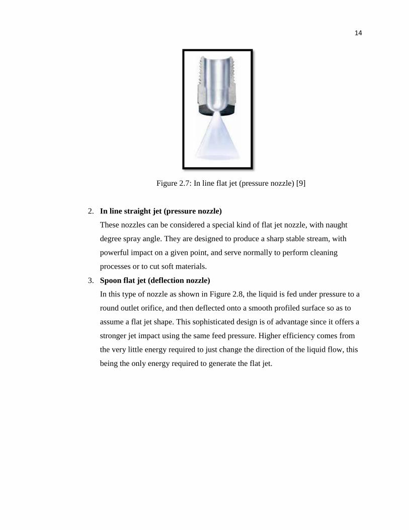
Figure 2.7: In line flat jet (pressure nozzle) [9]
2. In line straight jet (pressure nozzle)
These nozzles can be considered a special kind of flat jet nozzle, with naught
degree spray angle. They are designed to produce a sharp stable stream, with
powerful impact on a given point, and serve normally to perform cleaning
processes or to cut soft materials.
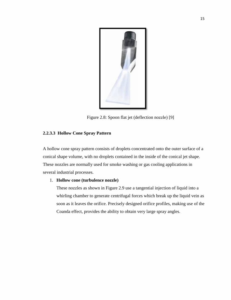
3. Spoon flat jet (deflection nozzle)
In this type of nozzle as shown in Figure 2.8, the liquid is fed under pressure to a
round outlet orifice, and then deflected onto a smooth profiled surface so as to
assume a flat jet shape. This sophisticated design is of advantage since it offers a
stronger jet impact using the same feed pressure. Higher efficiency comes from
the very little energy required to just change the direction of the liquid flow, this
being the only energy required to generate the flat jet.
15
Figure 2.8: Spoon flat jet (deflection nozzle) [9]
2.2.3.3 Hollow Cone Spray Pattern
A hollow cone spray pattern consists of droplets concentrated onto the outer surface of a
conical shape volume, with no droplets contained in the inside of the conical jet shape.
These nozzles are normally used for smoke washing or gas cooling applications in
several industrial processes.
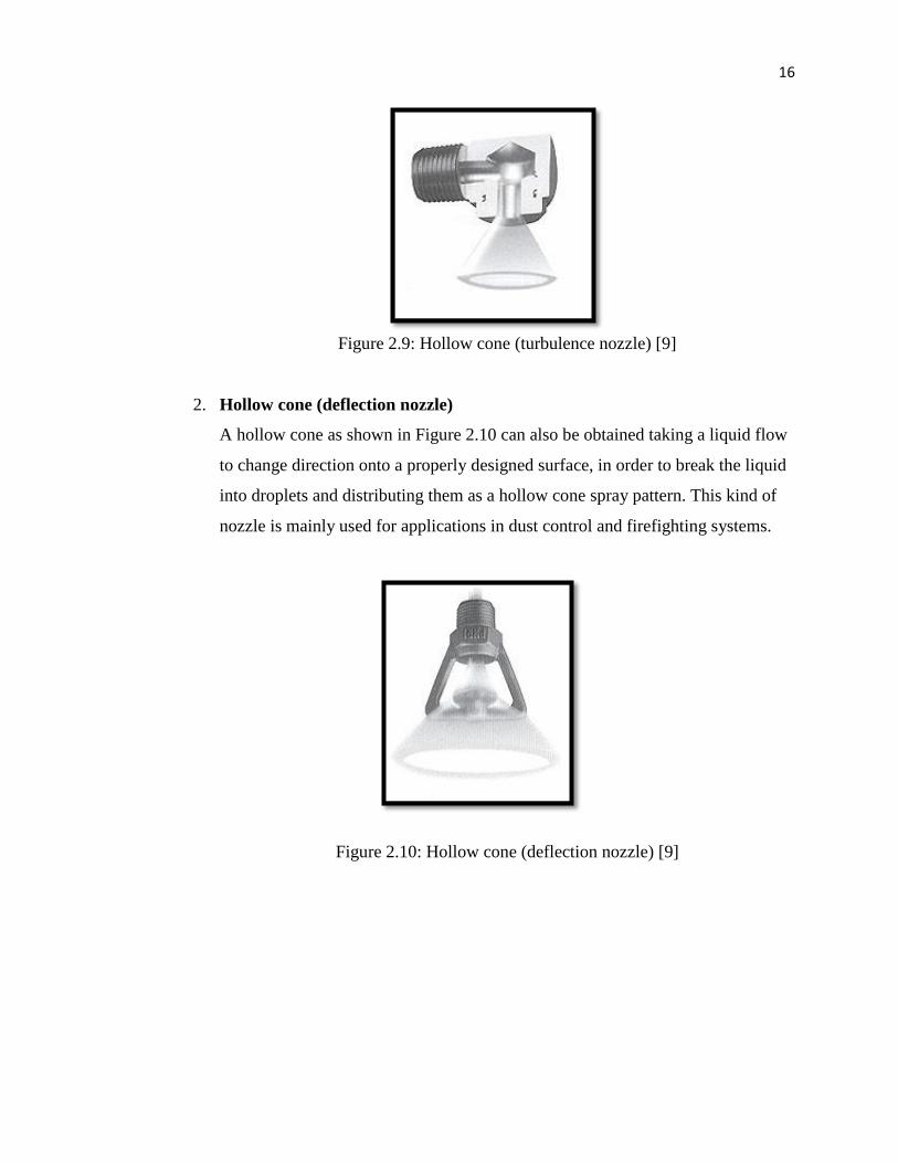
1. Hollow cone (turbulence nozzle)
These nozzles as shown in Figure 2.9 use a tangential injection of liquid into a
whirling chamber to generate centrifugal forces which break up the liquid vein as
soon as it leaves the orifice. Precisely designed orifice profiles, making use of the
Coanda effect, provides the ability to obtain very large spray angles.
16
Figure 2.9: Hollow cone (turbulence nozzle) [9]
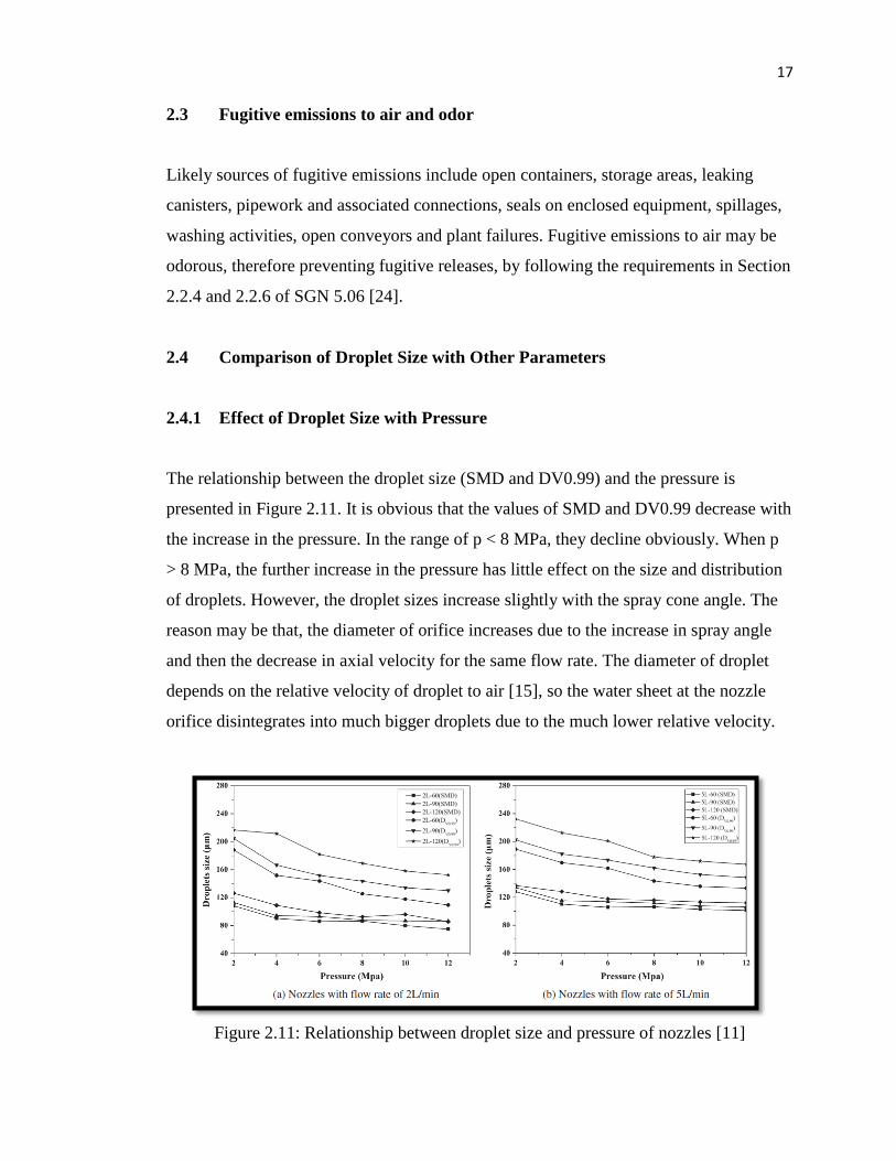
2. Hollow cone (deflection nozzle)
A hollow cone as shown in Figure 2.10 can also be obtained taking a liquid flow
to change direction onto a properly designed surface, in order to break the liquid
into droplets and distributing them as a hollow cone spray pattern. This kind of
nozzle is mainly used for applications in dust control and firefighting systems.
Figure 2.10: Hollow cone (deflection nozzle) [9]
17
2.3 Fugitive emissions to air and odor
Likely sources of fugitive emissions include open containers, storage areas, leaking
canisters, pipework and associated connections, seals on enclosed equipment, spillages,
washing activities, open conveyors and plant failures. Fugitive emissions to air may be
odorous, therefore preventing fugitive releases, by following the requirements in Section
2.2.4 and 2.2.6 of SGN 5.06 [24].
2.4 Comparison of Droplet Size with Other Parameters
2.4.1 Effect of Droplet Size with Pressure
The relationship between the droplet size (SMD and DV0.99) and the pressure is
presented in Figure 2.11. It is obvious that the values of SMD and DV0.99 decrease with
the increase in the pressure. In the range of p < 8 MPa, they decline obviously. When p
> 8 MPa, the further increase in the pressure has little effect on the size and distribution
of droplets. However, the droplet sizes increase slightly with the spray cone angle. The
reason may be that, the diameter of orifice increases due to the increase in spray angle
and then the decrease in axial velocity for the same flow rate. The diameter of droplet
depends on the relative velocity of droplet to air [15], so the water sheet at the nozzle
orifice disintegrates into much bigger droplets due to the much lower relative velocity.
Figure 2.11: Relationship between droplet size and pressure of nozzles [11]
18
2.4.2 Effect of Droplet Size with Flow Rate
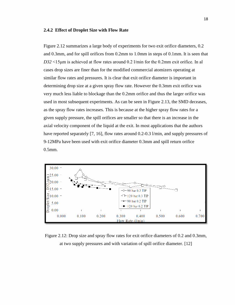
Figure 2.12 summarizes a large body of experiments for two exit orifice diameters, 0.2
and 0.3mm, and for spill orifices from 0.2mm to 1.0mm in steps of 0.1mm. It is seen that
D32 <15μm is achieved at flow rates around 0.2 l/min for the 0.2mm exit orifice. In al
cases drop sizes are finer than for the modified commercial atomizers operating at
similar flow rates and pressures. It is clear that exit orifice diameter is important in
determining drop size at a given spray flow rate. However the 0.3mm exit orifice was
very much less liable to blockage than the 0.2mm orifice and thus the larger orifice was
used in most subsequent experiments. As can be seen in Figure 2.13, the SMD deceases,
as the spray flow rates increases. This is because at the higher spray flow rates for a
given supply pressure, the spill orifices are smaller so that there is an increase in the
axial velocity component of the liquid at the exit. In most applications that the authors
have reported separately [7, 16], flow rates around 0.2-0.3 l/min, and supply pressures of
9-12MPa have been used with exit orifice diameter 0.3mm and spill return orifice
0.5mm.
Figure 2.12: Drop size and spray flow rates for exit orifice diameters of 0.2 and 0.3mm,
at two supply pressures and with variation of spill orifice diameter. [12]
19
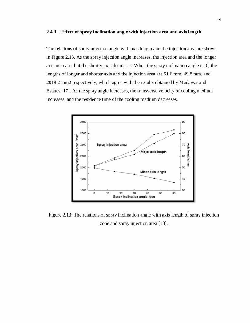
2.4.3 Effect of spray inclination angle with injection area and axis length
The relations of spray injection angle with axis length and the injection area are shown
in Figure 2.13. As the spray injection angle increases, the injection area and the longer
axis increase, but the shorter axis decreases. When the spray inclination angle is 0°, the
lengths of longer and shorter axis and the injection area are 51.6 mm, 49.8 mm, and
2018.2 mm2 respectively, which agree with the results obtained by Mudawar and
Estates [17]. As the spray angle increases, the transverse velocity of cooling medium
increases, and the residence time of the cooling medium decreases.
Figure 2.13: The relations of spray inclination angle with axis length of spray injection
zone and spray injection area [18].
20
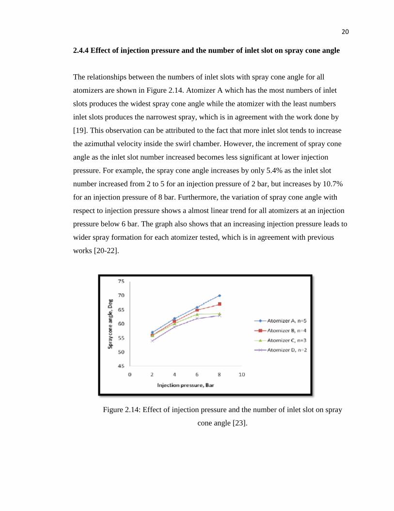
2.4.4 Effect of injection pressure and the number of inlet slot on spray cone angle
The relationships between the numbers of inlet slots with spray cone angle for all
atomizers are shown in Figure 2.14. Atomizer A which has the most numbers of inlet
slots produces the widest spray cone angle while the atomizer with the least numbers
inlet slots produces the narrowest spray, which is in agreement with the work done by
[19]. This observation can be attributed to the fact that more inlet slot tends to increase
the azimuthal velocity inside the swirl chamber. However, the increment of spray cone
angle as the inlet slot number increased becomes less significant at lower injection
pressure. For example, the spray cone angle increases by only 5.4% as the inlet slot
number increased from 2 to 5 for an injection pressure of 2 bar, but increases by 10.7%
for an injection pressure of 8 bar. Furthermore, the variation of spray cone angle with
respect to injection pressure shows a almost linear trend for all atomizers at an injection
pressure below 6 bar. The graph also shows that an increasing injection pressure leads to
wider spray formation for each atomizer tested, which is in agreement with previous
works [20-22].
Figure 2.14: Effect of injection pressure and the number of inlet slot on spray
cone angle [23].
21
CHAPTER 3
METHODOLOGY
3.1 Introduction
The methodology of the whole research is outlined in Figure 3.1 and Figure 3.2,
focusing towards achieving the specified research goals. This chapter will describes the
methods used to carry out simulation and experimental for fine spray nozzle. ANSYS
FLUENT version 14.5 software will be used to make a simulation and high speed
camera will be used for experimental part to visualize the spray pattern. Simulation is
the way to show the characteristic of nozzle spray and experiments will be conduct in
the aerodynamics laboratory. All devices used for experiment and experimental
procedures were arranged sequentially. The research methodology will be further
discussed in this chapter.
22
Figure 3.1: Experimental flowchart
Set up the experiment
for fine spray nozzle
Test the fine spray
nozzle performance
Performance
approval
Record the video for
spray by using high
speed camera
Data analysis
Collecting data
Start
End
No
Yes
23
Figure 3.2: Modelling flowchart
Start
Geometry
Meshing
Boundary
condition
Solver
Post
processing
Data analysis
End
Result
No
Yes
24
3.2 Experimental procedure
There are a few steps must be ready before start the experiment. Firstly, identified every
single of the apparatus and equipment that need to used. Make a schematic diagram for
experimental setup as a first idea before move on into the real experiment. Finally, set
the procedure to get the spray pattern.
3.2.1 Apparatus and equipment
It is very important to know the function of all equipment that will be used to ensure that
equipment being used is suitable for experiments to be carried out. All equipment should
be in good condition and equipment operator must know how to operate the equipment
that will be used for experiments.
a) High speed camera
High speed camera are shown in Figure 3.3 was used for recording fast-moving
objects like an image of spray onto a storage medium. After recording, the
images stored on the medium can be played back in slow-motion. So, the particle
of spray droplet can visualize clearly.
Figure 3.3: High speed camera
71
REFERENCES
[1] Arthur H. Lefebvre. Atomization and Sprays. Florida. Taylor & Francis Group.
1989.
[2] Mohd. Syazwan Bin Zulkipli. Development of a New Type of Sprayer Head of a
Water Mist System. Bachelor Thesis. Universiti Malaysia Pahang. 2012
[3] Spraying System Co. A Guide and Conditioning in Cement Manufacturing.
USA: Trade Brochure. 2004.
[4] Dipl. Ing Danielle Suzi. Diesel Nozzle Flow and Spray Formation: Coupled
Simulations with Real Engine Validation. Ph.D. Universitat Stuttgart. 2009
[5] Ikeuchi USA, Inc. Spray Nozzles Technical Information. Catalogue. 2008
[6] Scott Bretthauer. Spray Droplet Size Monitor. Retrieved on December, 2013,
http://web.extension.illinois.edu/ipr/i8793_829.html
[7] Nasr G.G., Yule A.J., Lloyd S.E., Whitehead A., Utilisation and Performance
Analysis of Fine Sprays for Disinfection within Healthcare, Proceedings of the
21st ILASS-EuropeConference, Turkey 2007.
[8] PNR. Spray Engineering Handbook. Europe. Commercial Catalogues. 2007
[9] Nozzle Network Co. Ltd. The World of Nozzles: Practical Edition Valuable Tips
on Selecting Nozzle. Retrieved on March, 2011,
http://www.nozzlenetwork.com/knowledge/know_practical_7.html
[10] Kansa State University State University Agricultural Experiment Station and
Cooperative Extension Service. United States. Commercial Catalogue. March
2000
72
[11] Liu Yinshui, Jiang Zhuo, Wang Dan, Li Xiaohui. Experimental research on the
water mist fire suppression performance in an enclosed space by changing the
characteristics of nozzles. 2014. 52 :174-181
[12] G.G. Nasr, A.J. Yule, S.E. Lloyd. The characterization of the spray from a new
fine spray spill return swirl atomizer. 2007. ILAAS
[13] Bjarne Paulsen Husted, Per Peterson, Ivar Lund, Goran Holmstedt. Comparison
of PIV and PDA droplet velocity measurement techniques on two high pressure
water mist nozzles. 2009. 44: 1030-1045
[14] Paolo E. Santangelo. Characterization of high pressure water mist sprays:
Experimental analysis of droplet size and dispersion. 2010. 34 :1353-1366
[15] S.P. Lin, R.D. Reitz, Drop and spray formation from a liquid jet, Annu. Rev.
Fluid Mech. 30 (1998) 85–105.
[16] Nasr G.G., Yule A.J., Lloyd S.E., The application of fine sprays for Chemical,
Biological, Radiological and Nuclear (CBRN) Decontamination, Proceedings of
the 21st ILASSEurope Conference, 2007, Turkey 2007.
[17] Mudawar, K.A. Estes, Optimizing and predicting CHF in spray cooling of a
square surface, Int. J. Heat Transfer 111 (1996) 672e679.
[18] T.L. Fu, Z.D. Wang, X.T. Deng, G.H. Liu, G.D. Wang, The influence of spray
inclination angle on the ultra-fast cooling of steel plate in spray cooling
condition, 2015. 78: 500-506.
[19] Hamid, A. H. A., Atan R., Noh, M. H. M., Rashid, H., 2011. Spray cone angle
and air core diameter of hollow cone swirl rocket injector. IIUM Engineering
Journal. Special Issue on Mechanical Engineering. 12, No 3.
[20] Hamid, A. H. A., Atan R. Spray characteristics of jet-swirl nozzles for thrust
chamber injector. Journal of Aerospace Science and Technology. 2009. 13,p
192-196.
[21] Yule, A.J., Widger, I. R . Swirl atomizer operating at high water pressure.
International Journal Mechanical Science. 1996. 38, no 8-9, pp 981-999.
[22] Halder, M.R., Dash, S.K., Som, S.K. A numerical and experimental investigation
on the coefficients of discharge and the spray cone angle of a solid cone swirl
73
nozzle. Journal of Experimental Thermal and Fluid Science. 2004. 28, p 297-
305.
[23] Mohd Syazwan, Ahmad Hussein, Ow Chee Sheng, Zulkifli. Effect of inlet slot
number on the spray cone angle and discharge coefficient of swirl atomizer.
2012. 1781-1786.
[24] Environment Agency. Sector Guidance Note: Recovery and Disposal of
Hazardous and Non-Hazardous Waste. S5.06. 2013
Related Documents