Citation: Meyer zu Reckendorf, I.; Sahki, A.; Perrin, D.; Lacoste, C.; Bergeret, A.; Ohayon, A.; Morand, K. Chemical Recycling of Vacuum-Infused Thermoplastic Acrylate-Based Composites Reinforced by Basalt Fabrics. Polymers 2022, 14, 1083. https://doi.org/10.3390/ polym14061083 Academic Editor: Somen K. Bhudolia Received: 4 February 2022 Accepted: 3 March 2022 Published: 8 March 2022 Publisher’s Note: MDPI stays neutral with regard to jurisdictional claims in published maps and institutional affil- iations. Copyright: © 2022 by the authors. Licensee MDPI, Basel, Switzerland. This article is an open access article distributed under the terms and conditions of the Creative Commons Attribution (CC BY) license (https:// creativecommons.org/licenses/by/ 4.0/). polymers Article Chemical Recycling of Vacuum-Infused Thermoplastic Acrylate-Based Composites Reinforced by Basalt Fabrics Inès Meyer zu Reckendorf 1,2 , Amel Sahki 1,2 , Didier Perrin 1, * , Clément Lacoste 1 , Anne Bergeret 1 , Avigaël Ohayon 2 and Karynn Morand 2 1 Polymers Composites and Hybrids (PCH), IMT Mines Alès, 30100 Alès, France; [email protected] (I.M.z.R.); [email protected] (A.S.); [email protected] (C.L.); [email protected] (A.B.) 2 SEGULA Technologies, 69200 Vénissieux, France; [email protected] (A.O.); [email protected] (K.M.) * Correspondence: [email protected] Abstract: The objective of this work was to compare the material recovered from different chemical recycling methodologies for thermoplastic acrylate-based composites reinforced by basalt fabrics and manufactured by vacuum infusion. Recycling was done via chemical dissolution with a preselected adapted solvent. The main goal of the study was to recover undamaged basalt fabrics in order to reuse them as reinforcements for “second-generation” composites. Two protocols were compared. The first one is based on an ultrasound technique, the second one on mechanical stirring. Dissolution kinetics as well as residual resin percentages were evaluated. Several parameters such as dissolution duration, dissolution temperature, and solvent/composite ratio were also studied. Recycled fabrics were characterized through SEM observations. Mechanical and thermomechanical properties of second-generation composites were determined and compared to those of virgin composites (called “first-generation” composites). The results show that the dissolution protocol using a mechanical stirring is more adapted to recover undamaged fabrics with no residual resin on their surface. Moreover, corresponding second-generation composites display equivalent mechanical properties than first generation ones. Keywords: recycling; thermoplastic composites; basalt fibers; ultrasound; mechanical properties 1. Introduction 1.1. Thermoplastic Composite Materials in the Automotive Industry In 2019, the global market of polymer-reinforced composites materials reached 17.7 mega- tons in volume with a value of $86 billion. In virtually every region of the world and every application sector, the composites market is growing in both volume and value. China (28%) and North America (26%) remain the largest markets in terms of volume, ahead of Europe (21%) and the rest of Asia (19%) [1]. The main industries using composites, in volume, are transportation (28%), ahead of construction (20%), electronics and electrical (16%), and pipes and tanks (15%) [1]. The automotive industry is one of the largest users of composites in the transportation sector owing to demand for weight reduction in vehicles; this is mainly driven by the demand for better fuel efficiency and reduced CO 2 emissions in order to comply with EU legislation. From 1 January 2020, this legislation set an EU fleet-wide target of 95 gCO 2 /km for the average emissions of new passenger cars and an EU fleet-wide target of 147 gCO 2 /km for the average emissions of new light commercial vehicles registered in the EU [2]. Moreover, a reduction in weight also implies lower environmental impacts (from <130 gCO 2 /km in 2015 to <95 gCO 2 /km by 2021). Composites can offer some lightening compared to other traditionally dominant structural materials (steel, aluminum, etc.) ranging from 15–25% for glass fiber reinforced polymers (GFRP) to nearly 25–40% for carbon fiber reinforced Polymers 2022, 14, 1083. https://doi.org/10.3390/polym14061083 https://www.mdpi.com/journal/polymers

Welcome message from author
This document is posted to help you gain knowledge. Please leave a comment to let me know what you think about it! Share it to your friends and learn new things together.
Transcript
�����������������
Citation: Meyer zu Reckendorf, I.;
Sahki, A.; Perrin, D.; Lacoste, C.;
Bergeret, A.; Ohayon, A.; Morand, K.
Chemical Recycling of
Vacuum-Infused Thermoplastic
Acrylate-Based Composites
Reinforced by Basalt Fabrics.
Polymers 2022, 14, 1083.
https://doi.org/10.3390/
polym14061083
Academic Editor: Somen K.
Bhudolia
Received: 4 February 2022
Accepted: 3 March 2022
Published: 8 March 2022
Publisher’s Note: MDPI stays neutral
with regard to jurisdictional claims in
published maps and institutional affil-
iations.
Copyright: © 2022 by the authors.
Licensee MDPI, Basel, Switzerland.
This article is an open access article
distributed under the terms and
conditions of the Creative Commons
Attribution (CC BY) license (https://
creativecommons.org/licenses/by/
4.0/).
polymers
Article
Chemical Recycling of Vacuum-Infused ThermoplasticAcrylate-Based Composites Reinforced by Basalt FabricsInès Meyer zu Reckendorf 1,2, Amel Sahki 1,2 , Didier Perrin 1,* , Clément Lacoste 1 , Anne Bergeret 1,Avigaël Ohayon 2 and Karynn Morand 2
1 Polymers Composites and Hybrids (PCH), IMT Mines Alès, 30100 Alès, France;[email protected] (I.M.z.R.); [email protected] (A.S.);[email protected] (C.L.); [email protected] (A.B.)
2 SEGULA Technologies, 69200 Vénissieux, France; [email protected] (A.O.);[email protected] (K.M.)
* Correspondence: [email protected]
Abstract: The objective of this work was to compare the material recovered from different chemicalrecycling methodologies for thermoplastic acrylate-based composites reinforced by basalt fabrics andmanufactured by vacuum infusion. Recycling was done via chemical dissolution with a preselectedadapted solvent. The main goal of the study was to recover undamaged basalt fabrics in order toreuse them as reinforcements for “second-generation” composites. Two protocols were compared.The first one is based on an ultrasound technique, the second one on mechanical stirring. Dissolutionkinetics as well as residual resin percentages were evaluated. Several parameters such as dissolutionduration, dissolution temperature, and solvent/composite ratio were also studied. Recycled fabricswere characterized through SEM observations. Mechanical and thermomechanical properties ofsecond-generation composites were determined and compared to those of virgin composites (called“first-generation” composites). The results show that the dissolution protocol using a mechanicalstirring is more adapted to recover undamaged fabrics with no residual resin on their surface.Moreover, corresponding second-generation composites display equivalent mechanical propertiesthan first generation ones.
Keywords: recycling; thermoplastic composites; basalt fibers; ultrasound; mechanical properties
1. Introduction1.1. Thermoplastic Composite Materials in the Automotive Industry
In 2019, the global market of polymer-reinforced composites materials reached 17.7 mega-tons in volume with a value of $86 billion. In virtually every region of the world and everyapplication sector, the composites market is growing in both volume and value. China(28%) and North America (26%) remain the largest markets in terms of volume, ahead ofEurope (21%) and the rest of Asia (19%) [1].
The main industries using composites, in volume, are transportation (28%), ahead ofconstruction (20%), electronics and electrical (16%), and pipes and tanks (15%) [1]. Theautomotive industry is one of the largest users of composites in the transportation sectorowing to demand for weight reduction in vehicles; this is mainly driven by the demand forbetter fuel efficiency and reduced CO2 emissions in order to comply with EU legislation.From 1 January 2020, this legislation set an EU fleet-wide target of 95 gCO2/km for theaverage emissions of new passenger cars and an EU fleet-wide target of 147 gCO2/km forthe average emissions of new light commercial vehicles registered in the EU [2]. Moreover,a reduction in weight also implies lower environmental impacts (from <130 gCO2/km in2015 to <95 gCO2/km by 2021). Composites can offer some lightening compared to othertraditionally dominant structural materials (steel, aluminum, etc.) ranging from 15–25%for glass fiber reinforced polymers (GFRP) to nearly 25–40% for carbon fiber reinforced
Polymers 2022, 14, 1083. https://doi.org/10.3390/polym14061083 https://www.mdpi.com/journal/polymers
Polymers 2022, 14, 1083 2 of 22
polymers (CFRP). The benefits of lightweight solutions can be translated into potentialsavings of 8 million tons of CO2 per year in the EU wide vehicle fleet [3].
Consequently, since the 2010s, car makers have been using composite materials forpassenger cells (CFRP), car roofs (both CFRP and GFRP), and fluid filter module (GFRP)of their cars [3,4]. Currently choosing CFRP as a chassis material for vehicles is a goodsolution because of its high strength and low weight. As the production cost of this typeof material tends to decrease, different types of CFRP are present in a vehicle chassis,such as the header above the windshield, door sills, transmission tunnel, front-to backand left-to-right roof reinforcement tubes and bows, the B-pillar between front and reardoors which provides structural support for the vehicle roof panel, the C-pillar (the verticalstructure behind the rear door), and rear parcel shelf [4]. GFRP have been gradually usedfor impact-absorbent automotive parts (such as instrument panel and inner door modules).
Glass fibers are by far the most used reinforcement (88%) all composite marketscombined [1], but other mineral fibers have been emerging over these last years. Amongthem, basalt fibers are one of the most promising.
Basalt fibers are made of solidified lava. The extrusion of this mineral allows theproduction of basalt fibers. This type of fiber has been widely used in the production ofreinforced concrete for floors, construction, and even roads. Currently, this fiber is attractingincreasing interest because of its lower cost than glass fibers for equivalent mechanicalproperties and its better alkaline resistance than E-glass fibers. In a review on basalt fibers,Fiore et al. [5] reported higher mechanical properties for basalt fibers compared to glassfibers with an elastic modulus of 89 GPa, and a tensile strength of 2.8 GPa (76 GPa and1.8–2.5 GPa, respectively, for E-glass fibers). As the density of basalt fibers (2800 kg/m3) ishigher than those of glass fibers (2560 kg/m3), equivalent specific mechanical propertiesare obtained for basalt fibers compared to glass fibers (around 30 GPa per kg/m3).
In the field of composite materials, thermoset resins are the most used (61%) aheadof thermoplastic resins (38%). Thermoplastic composites have become a real industrialalternative to traditional thermoset composites due to several benefits—among them, thefact that they are recyclable and take part to circular economy [6]. At present, the morecommonly used thermoplastic matrices in the automotive industry are polypropylene (PP),polyamide 6 (PA6), polyamide 6.6 (PA66), polyoxymethylene (polyacetal) (POM), high den-sity polyethylene (HDPE), poly(methyl methacrylate) (PMMA), polycarbonates (PC) andpolyvinyl chloride (PVC), acrylonitrile butadiene styrene (ABS), and polyetheretherketone(PEEK) [7,8].
Elium® resin is a new thermoplastic polymer produced by Arkema Co. (ParisVillepinte, France) since 2014. It is obtained from a low viscosity reactive mixture ofpolymer solutions of methacrylic monomers (methyl methacrylate (MMA), alkyl acrylic)and acrylic copolymer chains (viscosity of 100 cPs) and possibly other comonomers. Itspolymerization is activated by a dibenzoyl peroxide as a thermal initiator and can be carriedout at room temperature in the presence of an iron salt catalyst [9]. Elium® resin is a resinadapted to the vacuum infusion process at room temperature. Regarding its mechanicalproperties, the tensile modulus is around 3.3 GPa and tensile strength is around 76 MPawith an elongation of 6% [6].
Elium®/basalt fibers composites appear to be a promising composite alternative,combining good specific mechanical properties for transportation applications and recy-cling potential.
1.2. Fiber Reinforced Composites Recycling Techniques
Different types of material recoveries could be employed to value the componentsof composites.
Firstly, mechanical recycling processes consist of crushing the materials after an initialcutting step into small pieces, a step common to all recycling techniques. This mechanicalprocess does not separate the fiber from the resin. Mechanical shredding has been applied
Polymers 2022, 14, 1083 3 of 22
more to GFRC, particularly SMC (Sheet Molding Compound) and BMC (Bulk MoldingCompound), but studies on CFRC also exist [10].
In addition, several thermal recycling processes allow the recovery of fibers by pyroly-sis, combustion, co-incineration, fluidized bed, and molten salt pyrolysis. The principle isto expose the material to high temperatures under oxidant or inert atmospheric conditionsto decompose the matrix.
The third technique of material recovery is chemical recycling, which is often asso-ciated to solvolysis, defined by the capability of the solvent to break the macromolecularchains as chemical dissolution of the matrix corresponds to the disentanglement of thechains thanks to solvation. There is therefore no breaking of macromolecular chains unlikesolvolysis. This technique offers a large number of possibilities with a wide range ofsolvents, temperatures, pressures, and catalysts.
Chemical recycling performed on acrylate (Elium®) based composites reinforced bybasalt fabrics will be evaluated in this work.
1.3. Chemical Recycling of Acrylate-Based Composites
The solvents considered able to dissolve PMMA are also able to dissolve Elium® resinbecause of the similar chemical structure of both acrylic polymers. The properties of thedifferent solvents can be controlled by the operating conditions (temperature, pressure,and reaction time) imposed on the process.
Evchuk et al. [11] studied the possibility of existing correlation between the PMMAdissolution rate and the structure or properties of the solvents, including polarity. Solventssuch as trichloromethane, trichloroethylene, 1,4-dioxane, cyclohexanone, acetophenone,ethyl acetate, pentyl acetate, and dimethyl formamide were studied by these authors at atemperature range of 30–70 ◦C. However, no correlation was highlighted. Trichloroethylenewas pointed out by these authors to be the best solvent for PMMA, while trichloromethanewas the poorest. For Evchuk et al. [11], polar solvents, such as ethyl acetate, tetrahydrofuran,and cyclohexanone, are adapted to dissolve PMMA.
In the works by Tschentscher et al. [12] and Gebhardt et al. [13], these latter solventswere also used to recycle CFRP based on Elium® 150 resin involving specimens of 200 mm× 180 mm. These latter were placed in a closed container with a selected solvent (acetone,acetophenone, ethyl acetate, or xylene). These composites were tested for two “compos-ite:solvent” ratios (1:10 and 1:20) and for three dissolution times (24 h, 48 h, 72 h) accordingto the solvent nature. The authors stated that a solvent ratio of 1:20 is recommended for atime-saving dissolution process (24 h). Ethyl acetate represents an environmentally friendlyalternative to the established room temperature-based recycling process using acetone. Theamount of Elium® recovered as well as the amount of Elium® remaining on the fibers wereclose for both solvents. Nevertheless, Elium® glass transition was nearer to virgin Elium®
one in the case of ethyl acetate than acetone. As concerns acetophenone, it was consideredby the authors to be a good solvent at higher temperatures.
The review of Oliveux et al. [10] reported several technologies for composites recyclingin order to recover fibers. Among them, Adherent Technologies, Inc. (ATI) (Albuquerque,NM, USA) in USA [14,15] use a wet chemical breakdown to recover carbon fibers fromindustrial waste composites as well as from end-of-life composite materials. From compari-son with different recycling techniques, the authors conclude that a process using a lowtemperature and low pressure is the most interesting in terms of quality of the recoveredfibers and of price. In France, Innoveox [16] proposes a technology based on supercriticalhydrolysis with the possibility to control the solvent properties and the reaction ratesby conducting pressure manipulations. Supercritical water (temperature > 374 ◦C andpressure > 221 bar) has been mainly applied to CFRC in order to recover carbon fibersof good quality without paying much attention to the products of the resin degradation.SACMO (Holnon, France) [17] has also been interested in the composite solvolysis processand filed in 2014 a patent proposing a device for solvolysis treatment of a solid compositematerial to extract fibers from the treated material. The reactor can have a volume from 25
Polymers 2022, 14, 1083 4 of 22
to 400 L. Pressure and heating can be applied. In addition, Panasonic Electric Works Co.(Tokyo, Japan) [18] has shown a willingness to exploit their hydrolysis process to recycle200 tons of GFRC (based on unsaturated polyester resin) manufacturing waste per year.Wastes are treated at 230 ◦C with subcritical water at 2.8 MPa with additives (NaOH, KOH)for 4 h.
1.4. The Use of Ultrasounds as Processing Aids for Solvolysis
For more efficient technologies and in an environmental friendlier approach, mechani-cal stirring and heating are unfavorable techniques that need a non-negligible amount ofenergy to be processed. It is the reason why ultrasound was preferentially used to replace acommonly used stirring mechanism during the recycling protocol as a greener alternative.
Das et al. [19] proposed a sono-chemical method to recover carbon fiber from CFRP.Epoxy/carbon fibers composites are treated with a mixture of dilute nitric acid and hy-drogen peroxide in the presence of ultrasound. Specimens of 30 mm × 25 mm × 2 mmare immersed for a pretreatment in the mixture until the samples are fully swollen. Thesolid-to-fluid ratio is maintained at 1:60. Then the sonication (470 kHz, 65 ◦C) begins ina water bath. The composite layer separation begins after 4 h. The total duration of thetreatment is 8 h. The recovered fibers have little or no epoxy resin on the surface andtheir tensile strength is comparable to virgin fibers. According to Das et al., the use ofultrasound in aqueous solutions leads to cavitation. Microbubbles implode on the surfaceof the composite and facilitate the degradation of the resin first on the surface and then inthe core of the composite, also by solvent diffusion.
Desai et al. [20] have already studied ultrasounds in order to depolymerize polymerssuch as polypropylene in p-xylene and decalin solvents. The degradation of PMMA usingultrasounds has also been studied. The authors have investigated the effect of alkyl groups’(such as methyl, ethyl or butyl groups) substituent on the ultrasonic degradation of PMMA,PEMA, and PBMA at 30 ◦C in toluene. The degradation rate constantly increases with anincrease in the number of carbon atoms in the alkyl group [21].
In terms of degradation mechanism, homolytic and/or heterolytic cleavage of acovalent bond may occur. However, the breakage of a C–C bond in the macromoleculeis the most common mechanism. Yan et al. [22] established a degradation mechanism ofaqueous solution of carboxylic curdlan by ultrasound treatment. The ultrasound treatment(15 min) implies a shear force that is responsible for the disaggregation of polymer clusters.Non-covalent intra- and intermolecular bonds are broken. As the time of the ultrasoundtreatment increases (30 min), chains are further split, and shorter random coil chains arecreated. A degradation process thus occurs.
This literature review revealed that, to the best of our knowledge, no investigationshave been carried on chemical recycling of Elium®/basalt fabrics composites as well onan academic and industrial point of view. Therefore, this paper provide new results onthis challenging new composite material and the best way to recover either the Elium®
resin or basalt fabrics to produce new composites that will be called “second generation”composites. To lower the carbon footprint of the process, an environmental-friendly solventand room temperature dissolution procedure will be chosen. In addition, this paper willanalyze the influence of ultrasound on the kinetics dissolution of Elium® resin to provide agreener approach, as compared to mechanical stirring and heating.
2. Materials and Methods2.1. Materials
This study focuses on basalt woven sized fibers in plain weave. This fabric supplied byBasaltex (Wevelgem, Belgium) has a basis weight of 220 g/m2 with a density of 2.65 g/cm3
and a fiber diameter of 13 µm. The resin Elium® 150 was provided by Arkema (Lacq,France). The resin has a low viscosity of 100 mPa.s and a density of 1.01 g/cm3. Ac-cording to the producer, its composition is a mixture of a methyl methacrylate copolymer(70–90 wt%), citral or 3,7-dimethyl-2,6-octadienal (≤5 wt%), hydro-treated light paraffinic
Polymers 2022, 14, 1083 5 of 22
distillates (petroleum) (≤2 wt%), and other additives. Perkadox® CH-50X dibenzoyl perox-ide, provided by AkzoNobel, was added to the resin to initiate the radical polymerisation(2 wt%). After 30 min at room temperature, an exothermic reaction occurred so that nopost-curing is required.
2.2. Composites Processing
“First generation” composites of 41 cm × 41 cm were manufactured by resin infusionat room temperature with 10 plies of fabric. Elium® resin and initiator (2 wt%) were mixed,and then infused under vacuum outlet until the surface of the fibres was covered with resin.The infused plate was left to polymerize at room temperature for 24 h without any furtherpost-curing. The composites obtained have an average thickness of about 1.68 mm anda mass fraction of 71% and volume fraction of 48% of fibres. The density was measuredthrough Micrometrics gas pycnometer with helium gas. It was 2.01 ± 0.02 g/cm3.
“Second generation” composites were also manufactured by resin infusion at roomtemperature with 10 plies of fabric. For each sample, all the 10 plies belong to the same re-covered sample from the first-generation composites. The composites from recycled fabricshave been infused in the dimensions necessary for the tensile tests, i.e., 125 mm × 25 mmunder the same processing parameters used for the first-generation counterparts.
2.3. Dissolution Parameters
Parameter selection. Different parameters were studied: the choice of solvent, thecomposite/solvent ratio, the dissolution time, the dissolution temperature, and the presenceof agitation or not. In this article are presented the results of the dissolution in acetone,comparing the influence of different composite/solvent ratio, time of dissolution and theuse of mechanical agitation, ultrasound, or simply dipped in the solvent and are describedin Table 1. For this purpose, the dissolution devices were adapted according to the protocolin order to obtain optimal results.
Table 1. Conditions of dissolution.
Parameters Conditions
Samples dimension 6 cm × 10 cm or 13.5 cm × 3.5 cmContainer 1 or 2 L reactor
Solvent Acetone 99.9% purity“Composite:solvent” ratio 1:4, 1:10, 1:40
Dissolution time 7, 16, 24, 48, 72 hTemperature 25 ◦C
Mechanical agitation Pale notched, 60 rpmUltrasounds 3 min applied at the beginning or end of dissolution
Sample preparation. For dissolution experiments, composites were cut using a circularraw. The dimensions were limited to a few square centimeters (from 6 cm × 10 cm and12.5 cm × 2.5 cm) for a good fixation into the reactor.
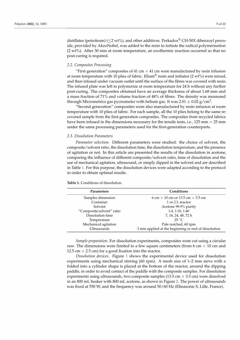
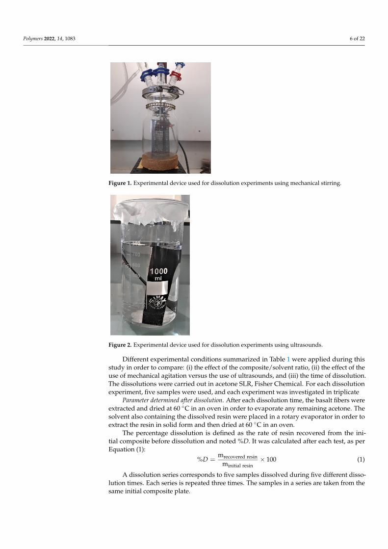
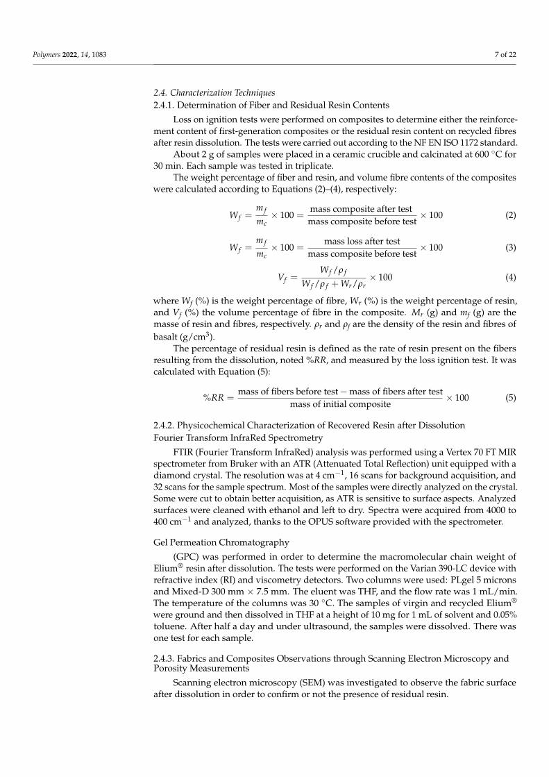
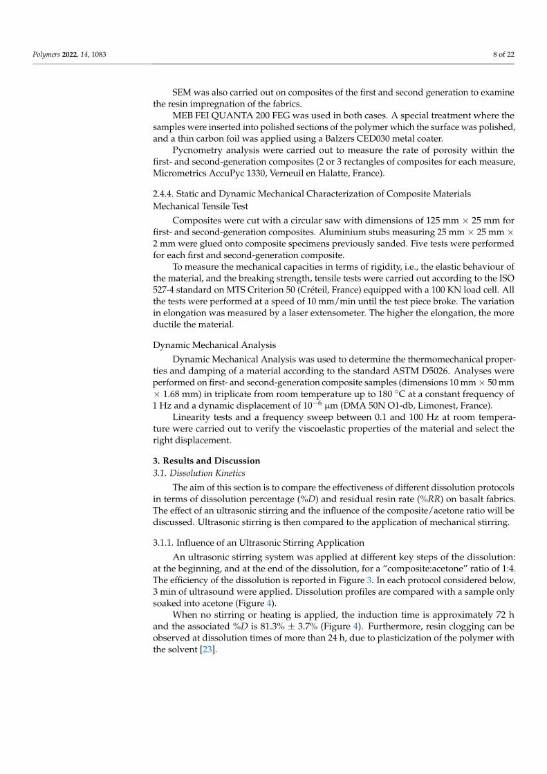
Dissolution devices. Figure 1 shows the experimental device used for dissolutionexperiments using mechanical stirring (60 rpm). A mesh size of 1–2 mm sieve with afolded into a cylinder shape is placed at the bottom of the reactor, around the dippingpaddle, in order to avoid contact of the paddle with the composite samples. For dissolutionexperiments using ultrasounds, two composite samples (13.5 cm × 3.5 cm) were dissolvedin an 800 mL beaker with 800 mL acetone, as shown in Figure 2. The power of ultrasoundswas fixed at 550 W, and the frequency was around 50/60 Hz (Elmasonic S, Lille, France).
Polymers 2022, 14, 1083 6 of 22Polymers 2022, 14, x FOR PEER REVIEW 6 of 22
Figure 1. Experimental device used for dissolution experiments using mechanical stirring.
Figure 2. Experimental device used for dissolution experiments using ultrasounds.
Different experimental conditions summarized in Table 1 were applied during this study in order to compare: (i) the effect of the composite/solvent ratio, (ii) the effect of the use of mechanical agitation versus the use of ultrasounds, and (iii) the time of dissolution. The dissolutions were carried out in acetone SLR, Fisher Chemical. For each dissolution experiment, five samples were used, and each experiment was investigated in triplicate
Parameter determined after dissolution. After each dissolution time, the basalt fibers were extracted and dried at 60 °C in an oven in order to evaporate any remaining acetone. The solvent also containing the dissolved resin were placed in a rotary evaporator in order to extract the resin in solid form and then dried at 60 °C in an oven.
The percentage dissolution is defined as the rate of resin recovered from the initial composite before dissolution and noted %D. It was calculated after each test, as per Equa-tion (1): %𝐷 = mrecovered resinminitial resin × 100 (1)
A dissolution series corresponds to five samples dissolved during five different dis-solution times. Each series is repeated three times. The samples in a series are taken from the same initial composite plate.
Figure 1. Experimental device used for dissolution experiments using mechanical stirring.
Polymers 2022, 14, x FOR PEER REVIEW 6 of 22
Figure 1. Experimental device used for dissolution experiments using mechanical stirring.
Figure 2. Experimental device used for dissolution experiments using ultrasounds.
Different experimental conditions summarized in Table 1 were applied during this study in order to compare: (i) the effect of the composite/solvent ratio, (ii) the effect of the use of mechanical agitation versus the use of ultrasounds, and (iii) the time of dissolution. The dissolutions were carried out in acetone SLR, Fisher Chemical. For each dissolution experiment, five samples were used, and each experiment was investigated in triplicate
Parameter determined after dissolution. After each dissolution time, the basalt fibers were extracted and dried at 60 °C in an oven in order to evaporate any remaining acetone. The solvent also containing the dissolved resin were placed in a rotary evaporator in order to extract the resin in solid form and then dried at 60 °C in an oven.
The percentage dissolution is defined as the rate of resin recovered from the initial composite before dissolution and noted %D. It was calculated after each test, as per Equa-tion (1): %𝐷 = mrecovered resinminitial resin × 100 (1)
A dissolution series corresponds to five samples dissolved during five different dis-solution times. Each series is repeated three times. The samples in a series are taken from the same initial composite plate.
Figure 2. Experimental device used for dissolution experiments using ultrasounds.
Different experimental conditions summarized in Table 1 were applied during thisstudy in order to compare: (i) the effect of the composite/solvent ratio, (ii) the effect of theuse of mechanical agitation versus the use of ultrasounds, and (iii) the time of dissolution.The dissolutions were carried out in acetone SLR, Fisher Chemical. For each dissolutionexperiment, five samples were used, and each experiment was investigated in triplicate
Parameter determined after dissolution. After each dissolution time, the basalt fibers wereextracted and dried at 60 ◦C in an oven in order to evaporate any remaining acetone. Thesolvent also containing the dissolved resin were placed in a rotary evaporator in order toextract the resin in solid form and then dried at 60 ◦C in an oven.
The percentage dissolution is defined as the rate of resin recovered from the ini-tial composite before dissolution and noted %D. It was calculated after each test, as perEquation (1):
%D =mrecovered resin
minitial resin× 100 (1)
A dissolution series corresponds to five samples dissolved during five different disso-lution times. Each series is repeated three times. The samples in a series are taken from thesame initial composite plate.
Polymers 2022, 14, 1083 7 of 22
2.4. Characterization Techniques2.4.1. Determination of Fiber and Residual Resin Contents
Loss on ignition tests were performed on composites to determine either the reinforce-ment content of first-generation composites or the residual resin content on recycled fibresafter resin dissolution. The tests were carried out according to the NF EN ISO 1172 standard.
About 2 g of samples were placed in a ceramic crucible and calcinated at 600 ◦C for30 min. Each sample was tested in triplicate.
The weight percentage of fiber and resin, and volume fibre contents of the compositeswere calculated according to Equations (2)–(4), respectively:
W f =m f
mc× 100 =
mass composite after testmass composite before test
× 100 (2)
W f =m f
mc× 100 =
mass loss after testmass composite before test
× 100 (3)
Vf =W f /ρ f
W f /ρ f + Wr/ρr× 100 (4)
where Wf (%) is the weight percentage of fibre, Wr (%) is the weight percentage of resin,and Vf (%) the volume percentage of fibre in the composite. Mr (g) and mf (g) are themasse of resin and fibres, respectively. ρr and ρf are the density of the resin and fibres ofbasalt (g/cm3).
The percentage of residual resin is defined as the rate of resin present on the fibersresulting from the dissolution, noted %RR, and measured by the loss ignition test. It wascalculated with Equation (5):
%RR =mass of fibers before test − mass of fibers after test
mass of initial composite× 100 (5)
2.4.2. Physicochemical Characterization of Recovered Resin after DissolutionFourier Transform InfraRed Spectrometry
FTIR (Fourier Transform InfraRed) analysis was performed using a Vertex 70 FT MIRspectrometer from Bruker with an ATR (Attenuated Total Reflection) unit equipped with adiamond crystal. The resolution was at 4 cm−1, 16 scans for background acquisition, and32 scans for the sample spectrum. Most of the samples were directly analyzed on the crystal.Some were cut to obtain better acquisition, as ATR is sensitive to surface aspects. Analyzedsurfaces were cleaned with ethanol and left to dry. Spectra were acquired from 4000 to400 cm−1 and analyzed, thanks to the OPUS software provided with the spectrometer.
Gel Permeation Chromatography
(GPC) was performed in order to determine the macromolecular chain weight ofElium® resin after dissolution. The tests were performed on the Varian 390-LC device withrefractive index (RI) and viscometry detectors. Two columns were used: PLgel 5 micronsand Mixed-D 300 mm × 7.5 mm. The eluent was THF, and the flow rate was 1 mL/min.The temperature of the columns was 30 ◦C. The samples of virgin and recycled Elium®
were ground and then dissolved in THF at a height of 10 mg for 1 mL of solvent and 0.05%toluene. After half a day and under ultrasound, the samples were dissolved. There wasone test for each sample.
2.4.3. Fabrics and Composites Observations through Scanning Electron Microscopy andPorosity Measurements
Scanning electron microscopy (SEM) was investigated to observe the fabric surfaceafter dissolution in order to confirm or not the presence of residual resin.
Polymers 2022, 14, 1083 8 of 22
SEM was also carried out on composites of the first and second generation to examinethe resin impregnation of the fabrics.
MEB FEI QUANTA 200 FEG was used in both cases. A special treatment where thesamples were inserted into polished sections of the polymer which the surface was polished,and a thin carbon foil was applied using a Balzers CED030 metal coater.
Pycnometry analysis were carried out to measure the rate of porosity within thefirst- and second-generation composites (2 or 3 rectangles of composites for each measure,Micrometrics AccuPyc 1330, Verneuil en Halatte, France).
2.4.4. Static and Dynamic Mechanical Characterization of Composite MaterialsMechanical Tensile Test
Composites were cut with a circular saw with dimensions of 125 mm × 25 mm forfirst- and second-generation composites. Aluminium stubs measuring 25 mm × 25 mm ×2 mm were glued onto composite specimens previously sanded. Five tests were performedfor each first and second-generation composite.
To measure the mechanical capacities in terms of rigidity, i.e., the elastic behaviour ofthe material, and the breaking strength, tensile tests were carried out according to the ISO527-4 standard on MTS Criterion 50 (Créteil, France) equipped with a 100 KN load cell. Allthe tests were performed at a speed of 10 mm/min until the test piece broke. The variationin elongation was measured by a laser extensometer. The higher the elongation, the moreductile the material.
Dynamic Mechanical Analysis
Dynamic Mechanical Analysis was used to determine the thermomechanical proper-ties and damping of a material according to the standard ASTM D5026. Analyses wereperformed on first- and second-generation composite samples (dimensions 10 mm × 50 mm× 1.68 mm) in triplicate from room temperature up to 180 ◦C at a constant frequency of1 Hz and a dynamic displacement of 10−6 µm (DMA 50N O1-db, Limonest, France).
Linearity tests and a frequency sweep between 0.1 and 100 Hz at room tempera-ture were carried out to verify the viscoelastic properties of the material and select theright displacement.
3. Results and Discussion3.1. Dissolution Kinetics
The aim of this section is to compare the effectiveness of different dissolution protocolsin terms of dissolution percentage (%D) and residual resin rate (%RR) on basalt fabrics.The effect of an ultrasonic stirring and the influence of the composite/acetone ratio will bediscussed. Ultrasonic stirring is then compared to the application of mechanical stirring.
3.1.1. Influence of an Ultrasonic Stirring Application
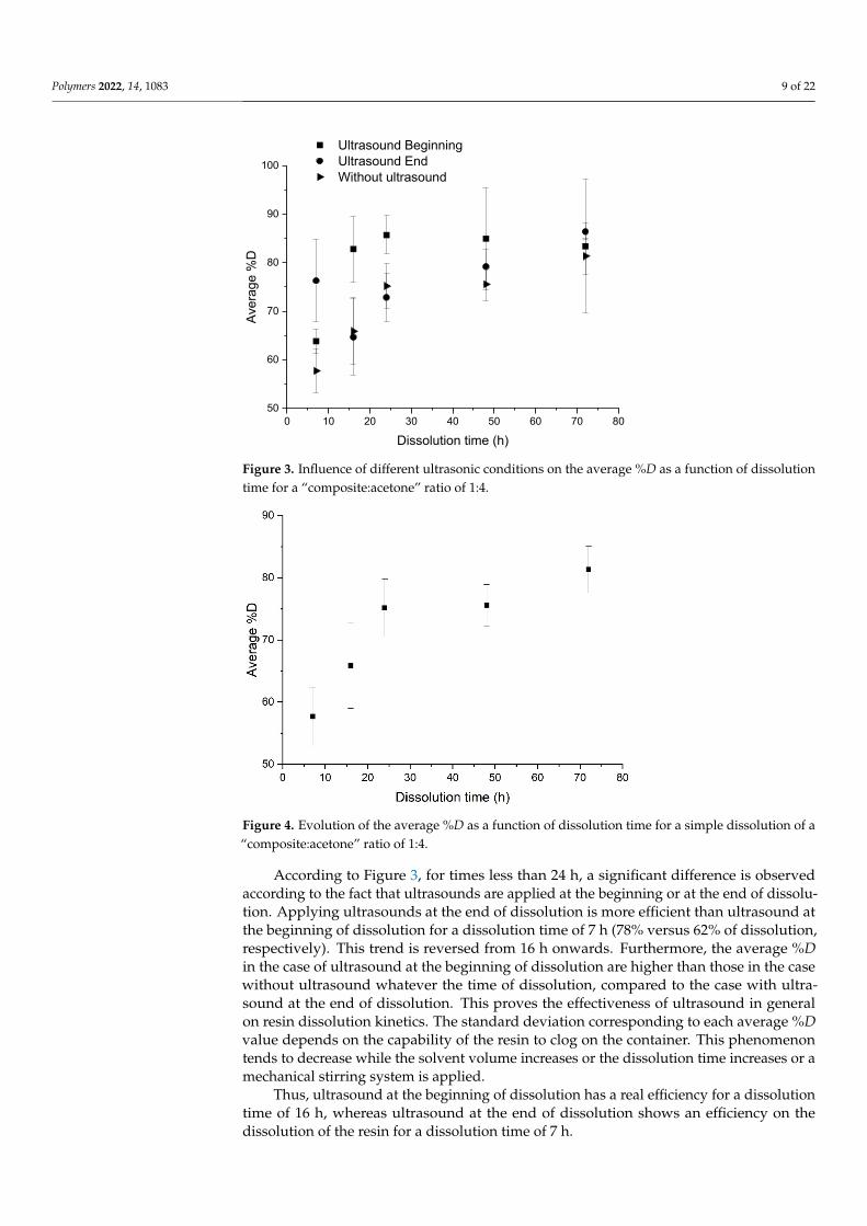
An ultrasonic stirring system was applied at different key steps of the dissolution:at the beginning, and at the end of the dissolution, for a “composite:acetone” ratio of 1:4.The efficiency of the dissolution is reported in Figure 3. In each protocol considered below,3 min of ultrasound were applied. Dissolution profiles are compared with a sample onlysoaked into acetone (Figure 4).
When no stirring or heating is applied, the induction time is approximately 72 hand the associated %D is 81.3% ± 3.7% (Figure 4). Furthermore, resin clogging can beobserved at dissolution times of more than 24 h, due to plasticization of the polymer withthe solvent [23].
Polymers 2022, 14, 1083 9 of 22Polymers 2022, 14, x FOR PEER REVIEW 9 of 22
Figure 3. Influence of different ultrasonic conditions on the average %D as a function of dissolution time for a “composite:acetone” ratio of 1:4.
Figure 4. Evolution of the average %D as a function of dissolution time for a simple dissolution of a “composite:acetone” ratio of 1:4.
When no stirring or heating is applied, the induction time is approximately 72 h and the associated %D is 81.3% ± 3.7% (Figure 4). Furthermore, resin clogging can be observed at dissolution times of more than 24 h, due to plasticization of the polymer with the sol-vent [23].
According to Figure 3, for times less than 24 h, a significant difference is observed according to the fact that ultrasounds are applied at the beginning or at the end of disso-lution. Applying ultrasounds at the end of dissolution is more efficient than ultrasound at the beginning of dissolution for a dissolution time of 7 h (78% versus 62% of dissolution, respectively). This trend is reversed from 16 h onwards. Furthermore, the average %D in the case of ultrasound at the beginning of dissolution are higher than those in the case without ultrasound whatever the time of dissolution, compared to the case with ultra-sound at the end of dissolution. This proves the effectiveness of ultrasound in general on resin dissolution kinetics. The standard deviation corresponding to each average %D
0 10 20 30 40 50 60 70 8050
60
70
80
90
100
Aver
age
%D
Dissolution time (h)
Ultrasound Beginning Ultrasound End Without ultrasound
Figure 3. Influence of different ultrasonic conditions on the average %D as a function of dissolutiontime for a “composite:acetone” ratio of 1:4.
Polymers 2022, 14, x FOR PEER REVIEW 9 of 22
Figure 3. Influence of different ultrasonic conditions on the average %D as a function of dissolution time for a “composite:acetone” ratio of 1:4.
Figure 4. Evolution of the average %D as a function of dissolution time for a simple dissolution of a “composite:acetone” ratio of 1:4.
When no stirring or heating is applied, the induction time is approximately 72 h and the associated %D is 81.3% ± 3.7% (Figure 4). Furthermore, resin clogging can be observed at dissolution times of more than 24 h, due to plasticization of the polymer with the sol-vent [23].
According to Figure 3, for times less than 24 h, a significant difference is observed according to the fact that ultrasounds are applied at the beginning or at the end of disso-lution. Applying ultrasounds at the end of dissolution is more efficient than ultrasound at the beginning of dissolution for a dissolution time of 7 h (78% versus 62% of dissolution, respectively). This trend is reversed from 16 h onwards. Furthermore, the average %D in the case of ultrasound at the beginning of dissolution are higher than those in the case without ultrasound whatever the time of dissolution, compared to the case with ultra-sound at the end of dissolution. This proves the effectiveness of ultrasound in general on resin dissolution kinetics. The standard deviation corresponding to each average %D
0 10 20 30 40 50 60 70 8050
60
70
80
90
100
Aver
age
%D
Dissolution time (h)
Ultrasound Beginning Ultrasound End Without ultrasound
Figure 4. Evolution of the average %D as a function of dissolution time for a simple dissolution of a“composite:acetone” ratio of 1:4.
According to Figure 3, for times less than 24 h, a significant difference is observedaccording to the fact that ultrasounds are applied at the beginning or at the end of dissolu-tion. Applying ultrasounds at the end of dissolution is more efficient than ultrasound atthe beginning of dissolution for a dissolution time of 7 h (78% versus 62% of dissolution,respectively). This trend is reversed from 16 h onwards. Furthermore, the average %Din the case of ultrasound at the beginning of dissolution are higher than those in the casewithout ultrasound whatever the time of dissolution, compared to the case with ultra-sound at the end of dissolution. This proves the effectiveness of ultrasound in generalon resin dissolution kinetics. The standard deviation corresponding to each average %Dvalue depends on the capability of the resin to clog on the container. This phenomenontends to decrease while the solvent volume increases or the dissolution time increases or amechanical stirring system is applied.
Thus, ultrasound at the beginning of dissolution has a real efficiency for a dissolutiontime of 16 h, whereas ultrasound at the end of dissolution shows an efficiency on thedissolution of the resin for a dissolution time of 7 h.
Polymers 2022, 14, 1083 10 of 22
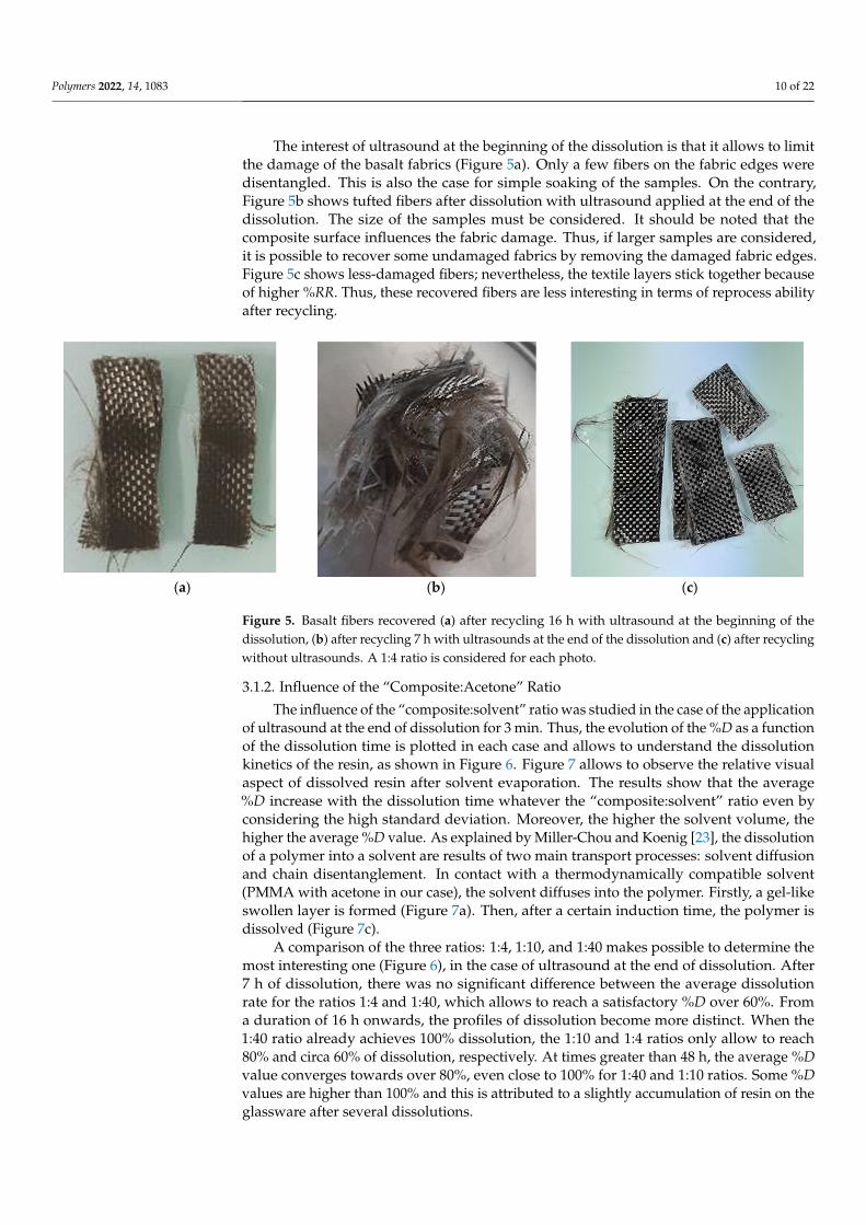
The interest of ultrasound at the beginning of the dissolution is that it allows to limitthe damage of the basalt fabrics (Figure 5a). Only a few fibers on the fabric edges weredisentangled. This is also the case for simple soaking of the samples. On the contrary,Figure 5b shows tufted fibers after dissolution with ultrasound applied at the end of thedissolution. The size of the samples must be considered. It should be noted that thecomposite surface influences the fabric damage. Thus, if larger samples are considered,it is possible to recover some undamaged fabrics by removing the damaged fabric edges.Figure 5c shows less-damaged fibers; nevertheless, the textile layers stick together becauseof higher %RR. Thus, these recovered fibers are less interesting in terms of reprocess abilityafter recycling.
Polymers 2022, 14, x FOR PEER REVIEW 10 of 22
value depends on the capability of the resin to clog on the container. This phenomenon tends to decrease while the solvent volume increases or the dissolution time increases or a mechanical stirring system is applied.
Thus, ultrasound at the beginning of dissolution has a real efficiency for a dissolution time of 16 h, whereas ultrasound at the end of dissolution shows an efficiency on the dis-solution of the resin for a dissolution time of 7 h.
The interest of ultrasound at the beginning of the dissolution is that it allows to limit the damage of the basalt fabrics (Figure 5a). Only a few fibers on the fabric edges were disentangled. This is also the case for simple soaking of the samples. On the contrary, Figure 5b shows tufted fibers after dissolution with ultrasound applied at the end of the dissolution. The size of the samples must be considered. It should be noted that the com-posite surface influences the fabric damage. Thus, if larger samples are considered, it is possible to recover some undamaged fabrics by removing the damaged fabric edges. Fig-ure 5c shows less-damaged fibers; nevertheless, the textile layers stick together because of higher %RR. Thus, these recovered fibers are less interesting in terms of reprocess ability after recycling.
(a) (b) (c)
Figure 5. Basalt fibers recovered (a) after recycling 16 h with ultrasound at the beginning of the dissolution, (b) after recycling 7 h with ultrasounds at the end of the dissolution and (c) after recy-cling without ultrasounds. A 1:4 ratio is considered for each photo.
3.1.2. Influence of the “Composite:Acetone” Ratio The influence of the “composite:solvent” ratio was studied in the case of the applica-
tion of ultrasound at the end of dissolution for 3 min. Thus, the evolution of the %D as a function of the dissolution time is plotted in each case and allows to understand the dis-solution kinetics of the resin, as shown in Figure 6. Figure 7 allows to observe the relative visual aspect of dissolved resin after solvent evaporation. The results show that the aver-age %D increase with the dissolution time whatever the “composite:solvent” ratio even by considering the high standard deviation. Moreover, the higher the solvent volume, the higher the average %D value. As explained by Miller-Chou and Koenig [23], the dissolu-tion of a polymer into a solvent are results of two main transport processes: solvent diffu-sion and chain disentanglement. In contact with a thermodynamically compatible solvent (PMMA with acetone in our case), the solvent diffuses into the polymer. Firstly, a gel-like swollen layer is formed (Figure 7a). Then, after a certain induction time, the polymer is dissolved (Figure 7c).
Figure 5. Basalt fibers recovered (a) after recycling 16 h with ultrasound at the beginning of thedissolution, (b) after recycling 7 h with ultrasounds at the end of the dissolution and (c) after recyclingwithout ultrasounds. A 1:4 ratio is considered for each photo.
3.1.2. Influence of the “Composite:Acetone” Ratio
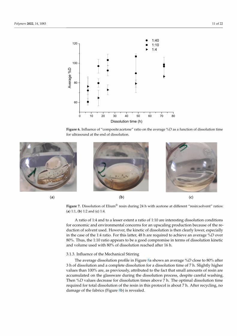
The influence of the “composite:solvent” ratio was studied in the case of the applicationof ultrasound at the end of dissolution for 3 min. Thus, the evolution of the %D as a functionof the dissolution time is plotted in each case and allows to understand the dissolutionkinetics of the resin, as shown in Figure 6. Figure 7 allows to observe the relative visualaspect of dissolved resin after solvent evaporation. The results show that the average%D increase with the dissolution time whatever the “composite:solvent” ratio even byconsidering the high standard deviation. Moreover, the higher the solvent volume, thehigher the average %D value. As explained by Miller-Chou and Koenig [23], the dissolutionof a polymer into a solvent are results of two main transport processes: solvent diffusionand chain disentanglement. In contact with a thermodynamically compatible solvent(PMMA with acetone in our case), the solvent diffuses into the polymer. Firstly, a gel-likeswollen layer is formed (Figure 7a). Then, after a certain induction time, the polymer isdissolved (Figure 7c).
A comparison of the three ratios: 1:4, 1:10, and 1:40 makes possible to determine themost interesting one (Figure 6), in the case of ultrasound at the end of dissolution. After7 h of dissolution, there was no significant difference between the average dissolutionrate for the ratios 1:4 and 1:40, which allows to reach a satisfactory %D over 60%. Froma duration of 16 h onwards, the profiles of dissolution become more distinct. When the1:40 ratio already achieves 100% dissolution, the 1:10 and 1:4 ratios only allow to reach80% and circa 60% of dissolution, respectively. At times greater than 48 h, the average %Dvalue converges towards over 80%, even close to 100% for 1:40 and 1:10 ratios. Some %Dvalues are higher than 100% and this is attributed to a slightly accumulation of resin on theglassware after several dissolutions.
Polymers 2022, 14, 1083 11 of 22
Polymers 2022, 14, x FOR PEER REVIEW 11 of 22
Figure 6. Influence of “composite:acetone” ratio on the average %D as a function of dissolution time for ultrasound at the end of dissolution.
(a) (b) (c)
Figure 7. Dissolution of Elium® resin during 24 h with acetone at different “resin:solvent” ratios: (a) 1:1, (b) 1:2 and (c) 1:4.
A comparison of the three ratios: 1:4, 1:10, and 1:40 makes possible to determine the most interesting one (Figure 6), in the case of ultrasound at the end of dissolution. After 7 h of dissolution, there was no significant difference between the average dissolution rate for the ratios 1:4 and 1:40, which allows to reach a satisfactory %D over 60%. From a du-ration of 16 h onwards, the profiles of dissolution become more distinct. When the 1:40 ratio already achieves 100% dissolution, the 1:10 and 1:4 ratios only allow to reach 80% and circa 60% of dissolution, respectively. At times greater than 48 h, the average %D value converges towards over 80%, even close to 100% for 1:40 and 1:10 ratios. Some %D values are higher than 100% and this is attributed to a slightly accumulation of resin on the glassware after several dissolutions.
A ratio of 1:4 and to a lesser extent a ratio of 1:10 are interesting dissolution conditions for economic and environmental concerns for an upscaling production because of the re-duction of solvent used. However, the kinetic of dissolution is then clearly lower, espe-cially in the case of the 1:4 ratio. For this latter, 48 h are required to achieve an average %D over 80%. Thus, the 1:10 ratio appears to be a good compromise in terms of dissolution kinetic and volume used with 80% of dissolution reached after 16 h.
0 10 20 30 40 50 60 70 80
60
80
100
120
Aver
age
%D
Dissolution time (h)
1:40 1:10 1:4
Figure 6. Influence of “composite:acetone” ratio on the average %D as a function of dissolution timefor ultrasound at the end of dissolution.
Polymers 2022, 14, x FOR PEER REVIEW 11 of 22
Figure 6. Influence of “composite:acetone” ratio on the average %D as a function of dissolution time for ultrasound at the end of dissolution.
(a) (b) (c)
Figure 7. Dissolution of Elium® resin during 24 h with acetone at different “resin:solvent” ratios: (a) 1:1, (b) 1:2 and (c) 1:4.
A comparison of the three ratios: 1:4, 1:10, and 1:40 makes possible to determine the most interesting one (Figure 6), in the case of ultrasound at the end of dissolution. After 7 h of dissolution, there was no significant difference between the average dissolution rate for the ratios 1:4 and 1:40, which allows to reach a satisfactory %D over 60%. From a du-ration of 16 h onwards, the profiles of dissolution become more distinct. When the 1:40 ratio already achieves 100% dissolution, the 1:10 and 1:4 ratios only allow to reach 80% and circa 60% of dissolution, respectively. At times greater than 48 h, the average %D value converges towards over 80%, even close to 100% for 1:40 and 1:10 ratios. Some %D values are higher than 100% and this is attributed to a slightly accumulation of resin on the glassware after several dissolutions.
A ratio of 1:4 and to a lesser extent a ratio of 1:10 are interesting dissolution conditions for economic and environmental concerns for an upscaling production because of the re-duction of solvent used. However, the kinetic of dissolution is then clearly lower, espe-cially in the case of the 1:4 ratio. For this latter, 48 h are required to achieve an average %D over 80%. Thus, the 1:10 ratio appears to be a good compromise in terms of dissolution kinetic and volume used with 80% of dissolution reached after 16 h.
0 10 20 30 40 50 60 70 80
60
80
100
120
Aver
age
%D
Dissolution time (h)
1:40 1:10 1:4
Figure 7. Dissolution of Elium® resin during 24 h with acetone at different “resin:solvent” ratios:(a) 1:1, (b) 1:2 and (c) 1:4.
A ratio of 1:4 and to a lesser extent a ratio of 1:10 are interesting dissolution conditionsfor economic and environmental concerns for an upscaling production because of the re-duction of solvent used. However, the kinetic of dissolution is then clearly lower, especiallyin the case of the 1:4 ratio. For this latter, 48 h are required to achieve an average %D over80%. Thus, the 1:10 ratio appears to be a good compromise in terms of dissolution kineticand volume used with 80% of dissolution reached after 16 h.
3.1.3. Influence of the Mechanical Stirring
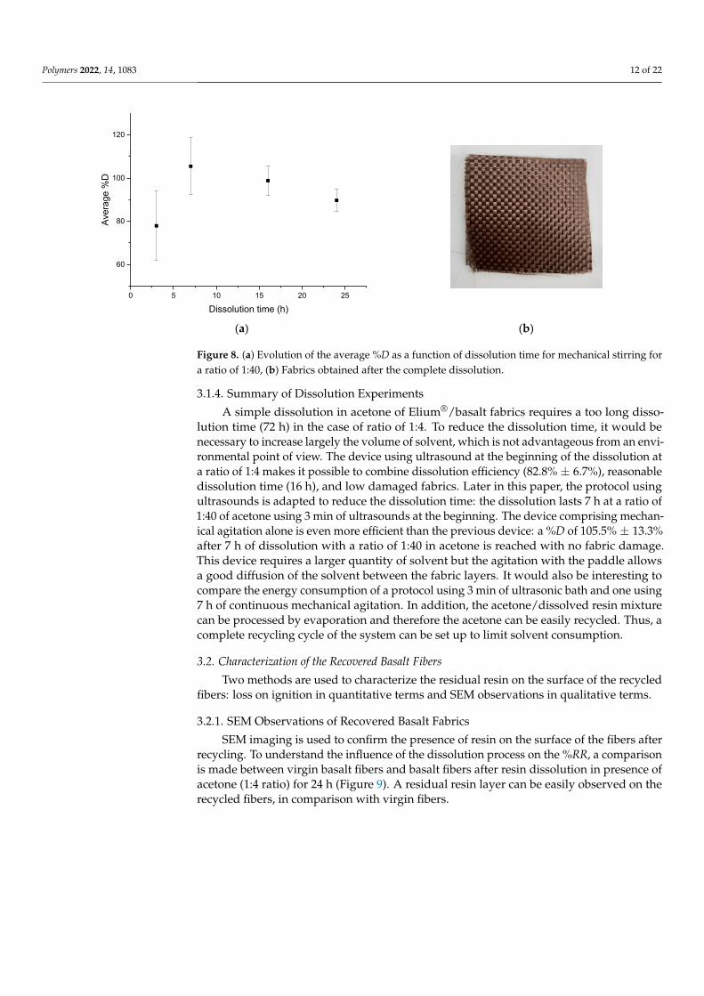
The average dissolution profile in Figure 8a shows an average %D close to 80% after3 h of dissolution and a complete dissolution for a dissolution time of 7 h. Slightly highervalues than 100% are, as previously, attributed to the fact that small amounts of resin areaccumulated on the glassware during the dissolution process, despite careful washing.Then %D values decrease for dissolution times above 7 h. The optimal dissolution timerequired for total dissolution of the resin in this protocol is about 7 h. After recycling, nodamage of the fabrics (Figure 8b) is revealed.
Polymers 2022, 14, 1083 12 of 22
Polymers 2022, 14, x FOR PEER REVIEW 12 of 22
3.1.3. Influence of the Mechanical Stirring The average dissolution profile in Figure 8a shows an average %D close to 80% after
3 h of dissolution and a complete dissolution for a dissolution time of 7 h. Slightly higher values than 100% are, as previously, attributed to the fact that small amounts of resin are accumulated on the glassware during the dissolution process, despite careful washing. Then %D values decrease for dissolution times above 7 h. The optimal dissolution time required for total dissolution of the resin in this protocol is about 7 h. After recycling, no damage of the fabrics (Figure 8b) is revealed.
(a) (b)
Figure 8. (a) Evolution of the average %D as a function of dissolution time for mechanical stirring for a ratio of 1:40, (b) Fabrics obtained after the complete dissolution.
3.1.4. Summary of Dissolution Experiments A simple dissolution in acetone of Elium®/basalt fabrics requires a too long dissolu-
tion time (72 h) in the case of ratio of 1:4. To reduce the dissolution time, it would be necessary to increase largely the volume of solvent, which is not advantageous from an environmental point of view. The device using ultrasound at the beginning of the disso-lution at a ratio of 1:4 makes it possible to combine dissolution efficiency (82.8% ± 6.7%), reasonable dissolution time (16 h), and low damaged fabrics. Later in this paper, the pro-tocol using ultrasounds is adapted to reduce the dissolution time: the dissolution lasts 7 h at a ratio of 1:40 of acetone using 3 min of ultrasounds at the beginning. The device com-prising mechanical agitation alone is even more efficient than the previous device: a %D of 105.5% ± 13.3% after 7 h of dissolution with a ratio of 1:40 in acetone is reached with no fabric damage. This device requires a larger quantity of solvent but the agitation with the paddle allows a good diffusion of the solvent between the fabric layers. It would also be interesting to compare the energy consumption of a protocol using 3 min of ultrasonic bath and one using 7 h of continuous mechanical agitation. In addition, the acetone/dis-solved resin mixture can be processed by evaporation and therefore the acetone can be easily recycled. Thus, a complete recycling cycle of the system can be set up to limit sol-vent consumption.
3.2. Characterization of the Recovered Basalt Fibers Two methods are used to characterize the residual resin on the surface of the recycled
fibers: loss on ignition in quantitative terms and SEM observations in qualitative terms.
0 5 10 15 20 25
60
80
100
120
Aver
age
%D
Dissolution time (h)
Figure 8. (a) Evolution of the average %D as a function of dissolution time for mechanical stirring fora ratio of 1:40, (b) Fabrics obtained after the complete dissolution.
3.1.4. Summary of Dissolution Experiments
A simple dissolution in acetone of Elium®/basalt fabrics requires a too long disso-lution time (72 h) in the case of ratio of 1:4. To reduce the dissolution time, it would benecessary to increase largely the volume of solvent, which is not advantageous from an envi-ronmental point of view. The device using ultrasound at the beginning of the dissolution ata ratio of 1:4 makes it possible to combine dissolution efficiency (82.8% ± 6.7%), reasonabledissolution time (16 h), and low damaged fabrics. Later in this paper, the protocol usingultrasounds is adapted to reduce the dissolution time: the dissolution lasts 7 h at a ratio of1:40 of acetone using 3 min of ultrasounds at the beginning. The device comprising mechan-ical agitation alone is even more efficient than the previous device: a %D of 105.5% ± 13.3%after 7 h of dissolution with a ratio of 1:40 in acetone is reached with no fabric damage.This device requires a larger quantity of solvent but the agitation with the paddle allowsa good diffusion of the solvent between the fabric layers. It would also be interesting tocompare the energy consumption of a protocol using 3 min of ultrasonic bath and one using7 h of continuous mechanical agitation. In addition, the acetone/dissolved resin mixturecan be processed by evaporation and therefore the acetone can be easily recycled. Thus, acomplete recycling cycle of the system can be set up to limit solvent consumption.
3.2. Characterization of the Recovered Basalt Fibers
Two methods are used to characterize the residual resin on the surface of the recycledfibers: loss on ignition in quantitative terms and SEM observations in qualitative terms.
3.2.1. SEM Observations of Recovered Basalt Fabrics
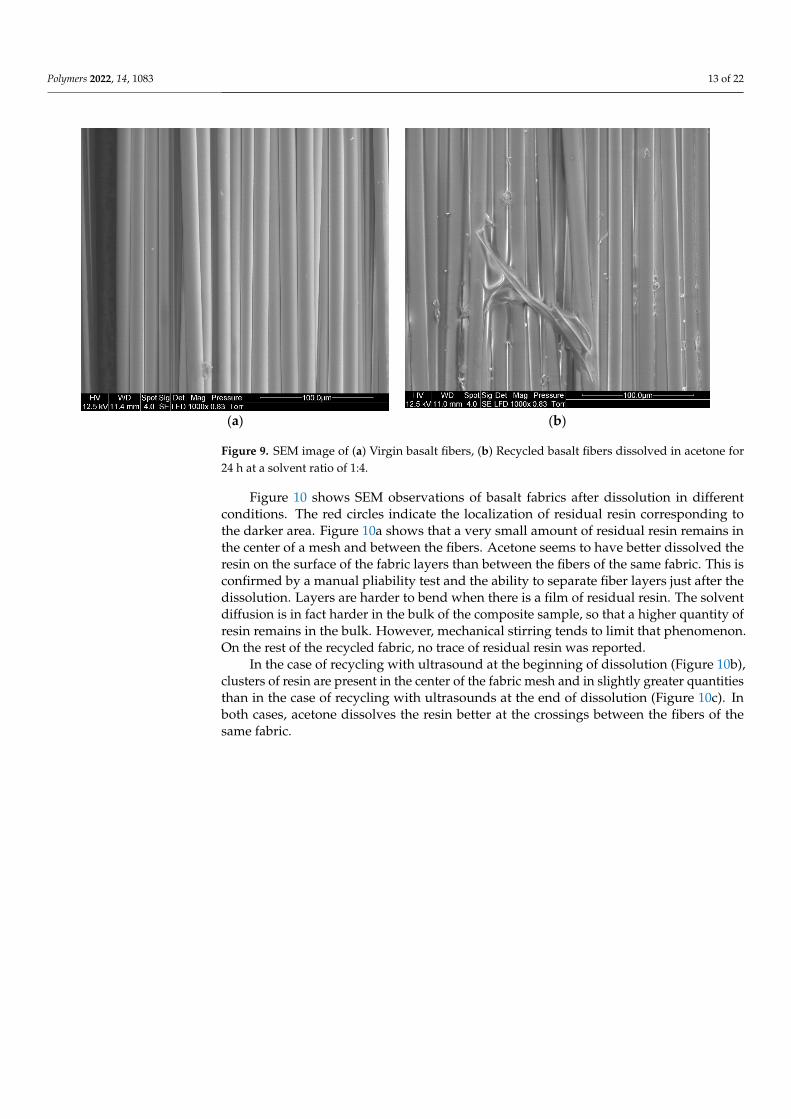
SEM imaging is used to confirm the presence of resin on the surface of the fibers afterrecycling. To understand the influence of the dissolution process on the %RR, a comparisonis made between virgin basalt fibers and basalt fibers after resin dissolution in presence ofacetone (1:4 ratio) for 24 h (Figure 9). A residual resin layer can be easily observed on therecycled fibers, in comparison with virgin fibers.
Polymers 2022, 14, 1083 13 of 22
Polymers 2022, 14, x FOR PEER REVIEW 13 of 22
3.2.1. SEM Observations of Recovered Basalt Fabrics SEM imaging is used to confirm the presence of resin on the surface of the fibers after
recycling. To understand the influence of the dissolution process on the %RR, a compari-son is made between virgin basalt fibers and basalt fibers after resin dissolution in pres-ence of acetone (1:4 ratio) for 24 h (Figure 9). A residual resin layer can be easily observed on the recycled fibers, in comparison with virgin fibers.
(a) (b)
Figure 9. SEM image of (a) Virgin basalt fibers, (b) Recycled basalt fibers dissolved in acetone for 24 h at a solvent ratio of 1:4.
Figure 10 shows SEM observations of basalt fabrics after dissolution in different con-ditions. The red circles indicate the localization of residual resin corresponding to the darker area. Figure 10a shows that a very small amount of residual resin remains in the center of a mesh and between the fibers. Acetone seems to have better dissolved the resin on the surface of the fabric layers than between the fibers of the same fabric. This is con-firmed by a manual pliability test and the ability to separate fiber layers just after the dis-solution. Layers are harder to bend when there is a film of residual resin. The solvent diffusion is in fact harder in the bulk of the composite sample, so that a higher quantity of resin remains in the bulk. However, mechanical stirring tends to limit that phenomenon. On the rest of the recycled fabric, no trace of residual resin was reported.
Figure 9. SEM image of (a) Virgin basalt fibers, (b) Recycled basalt fibers dissolved in acetone for24 h at a solvent ratio of 1:4.
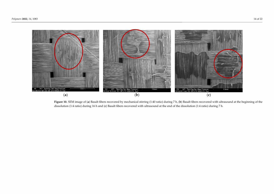
Figure 10 shows SEM observations of basalt fabrics after dissolution in differentconditions. The red circles indicate the localization of residual resin corresponding tothe darker area. Figure 10a shows that a very small amount of residual resin remains inthe center of a mesh and between the fibers. Acetone seems to have better dissolved theresin on the surface of the fabric layers than between the fibers of the same fabric. This isconfirmed by a manual pliability test and the ability to separate fiber layers just after thedissolution. Layers are harder to bend when there is a film of residual resin. The solventdiffusion is in fact harder in the bulk of the composite sample, so that a higher quantity ofresin remains in the bulk. However, mechanical stirring tends to limit that phenomenon.On the rest of the recycled fabric, no trace of residual resin was reported.
In the case of recycling with ultrasound at the beginning of dissolution (Figure 10b),clusters of resin are present in the center of the fabric mesh and in slightly greater quantitiesthan in the case of recycling with ultrasounds at the end of dissolution (Figure 10c). Inboth cases, acetone dissolves the resin better at the crossings between the fibers of thesame fabric.
Polymers 2022, 14, 1083 14 of 22Polymers 2022, 14, x FOR PEER REVIEW 14 of 22
(a) (b) (c)
Figure 10. SEM image of (a) Basalt fibers recovered by mechanical stirring (1:40 ratio) during 7 h, (b) Basalt fibers recovered with ultrasound at the beginning of the dissolution (1:4 ratio) during 16 h and (c) Basalt fibers recovered with ultrasound at the end of the dissolution (1:4 ratio) during 7 h.
Figure 10. SEM image of (a) Basalt fibers recovered by mechanical stirring (1:40 ratio) during 7 h, (b) Basalt fibers recovered with ultrasound at the beginning of thedissolution (1:4 ratio) during 16 h and (c) Basalt fibers recovered with ultrasound at the end of the dissolution (1:4 ratio) during 7 h.
Polymers 2022, 14, 1083 15 of 22
3.2.2. Residual Resin Rate on Basalt Fabrics
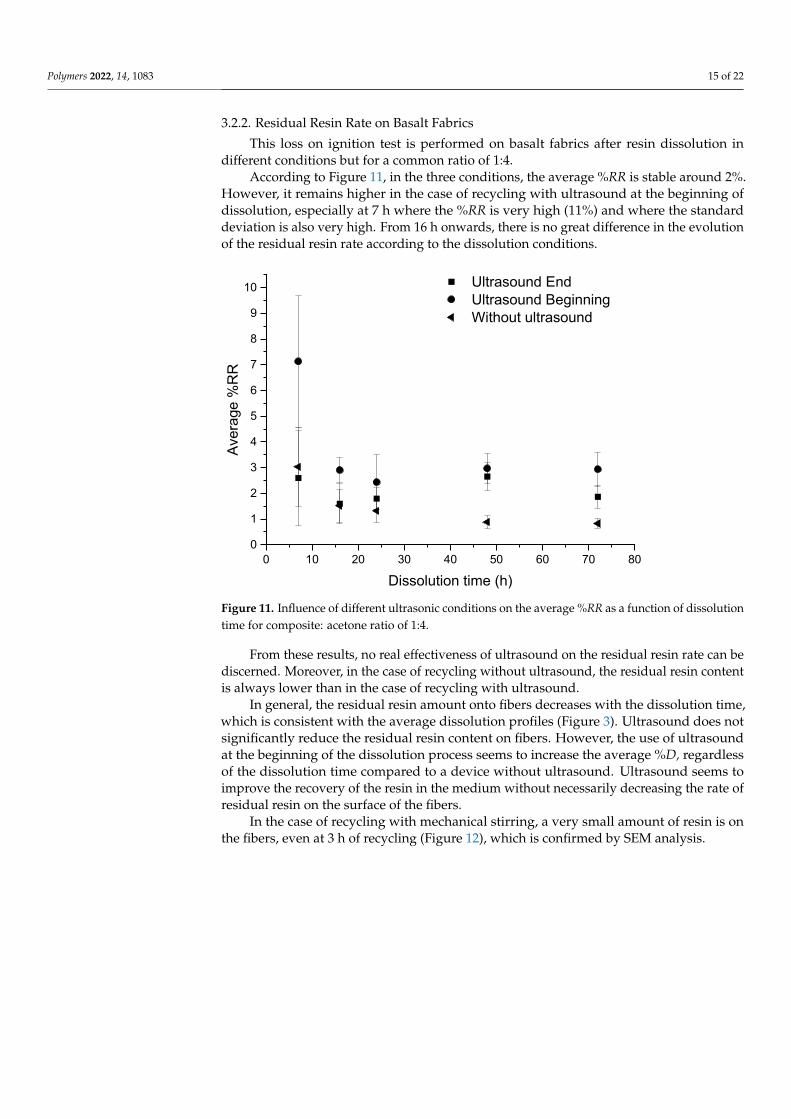
This loss on ignition test is performed on basalt fabrics after resin dissolution indifferent conditions but for a common ratio of 1:4.
According to Figure 11, in the three conditions, the average %RR is stable around 2%.However, it remains higher in the case of recycling with ultrasound at the beginning ofdissolution, especially at 7 h where the %RR is very high (11%) and where the standarddeviation is also very high. From 16 h onwards, there is no great difference in the evolutionof the residual resin rate according to the dissolution conditions.
Polymers 2022, 14, x FOR PEER REVIEW 15 of 22
In the case of recycling with ultrasound at the beginning of dissolution (Figure 10b), clusters of resin are present in the center of the fabric mesh and in slightly greater quanti-ties than in the case of recycling with ultrasounds at the end of dissolution (Figure 10c). In both cases, acetone dissolves the resin better at the crossings between the fibers of the same fabric.
3.2.2. Residual Resin Rate on Basalt Fabrics This loss on ignition test is performed on basalt fabrics after resin dissolution in dif-
ferent conditions but for a common ratio of 1:4. According to Figure 11, in the three conditions, the average %RR is stable around 2%.
However, it remains higher in the case of recycling with ultrasound at the beginning of dissolution, especially at 7 h where the %RR is very high (11%) and where the standard deviation is also very high. From 16 h onwards, there is no great difference in the evolu-tion of the residual resin rate according to the dissolution conditions.
Figure 11. Influence of different ultrasonic conditions on the average %RR as a function of dissolu-tion time for composite: acetone ratio of 1:4.
From these results, no real effectiveness of ultrasound on the residual resin rate can be discerned. Moreover, in the case of recycling without ultrasound, the residual resin content is always lower than in the case of recycling with ultrasound.
In general, the residual resin amount onto fibers decreases with the dissolution time, which is consistent with the average dissolution profiles (Figure 3). Ultrasound does not significantly reduce the residual resin content on fibers. However, the use of ultrasound at the beginning of the dissolution process seems to increase the average %D, regardless of the dissolution time compared to a device without ultrasound. Ultrasound seems to improve the recovery of the resin in the medium without necessarily decreasing the rate of residual resin on the surface of the fibers.
In the case of recycling with mechanical stirring, a very small amount of resin is on the fibers, even at 3 h of recycling (Figure 12), which is confirmed by SEM analysis.
0 10 20 30 40 50 60 70 800
1
2
3
4
5
6
7
8
9
10
Aver
age
%R
R
Dissolution time (h)
Ultrasound End Ultrasound Beginning Without ultrasound
Figure 11. Influence of different ultrasonic conditions on the average %RR as a function of dissolutiontime for composite: acetone ratio of 1:4.
From these results, no real effectiveness of ultrasound on the residual resin rate can bediscerned. Moreover, in the case of recycling without ultrasound, the residual resin contentis always lower than in the case of recycling with ultrasound.
In general, the residual resin amount onto fibers decreases with the dissolution time,which is consistent with the average dissolution profiles (Figure 3). Ultrasound does notsignificantly reduce the residual resin content on fibers. However, the use of ultrasoundat the beginning of the dissolution process seems to increase the average %D, regardlessof the dissolution time compared to a device without ultrasound. Ultrasound seems toimprove the recovery of the resin in the medium without necessarily decreasing the rate ofresidual resin on the surface of the fibers.
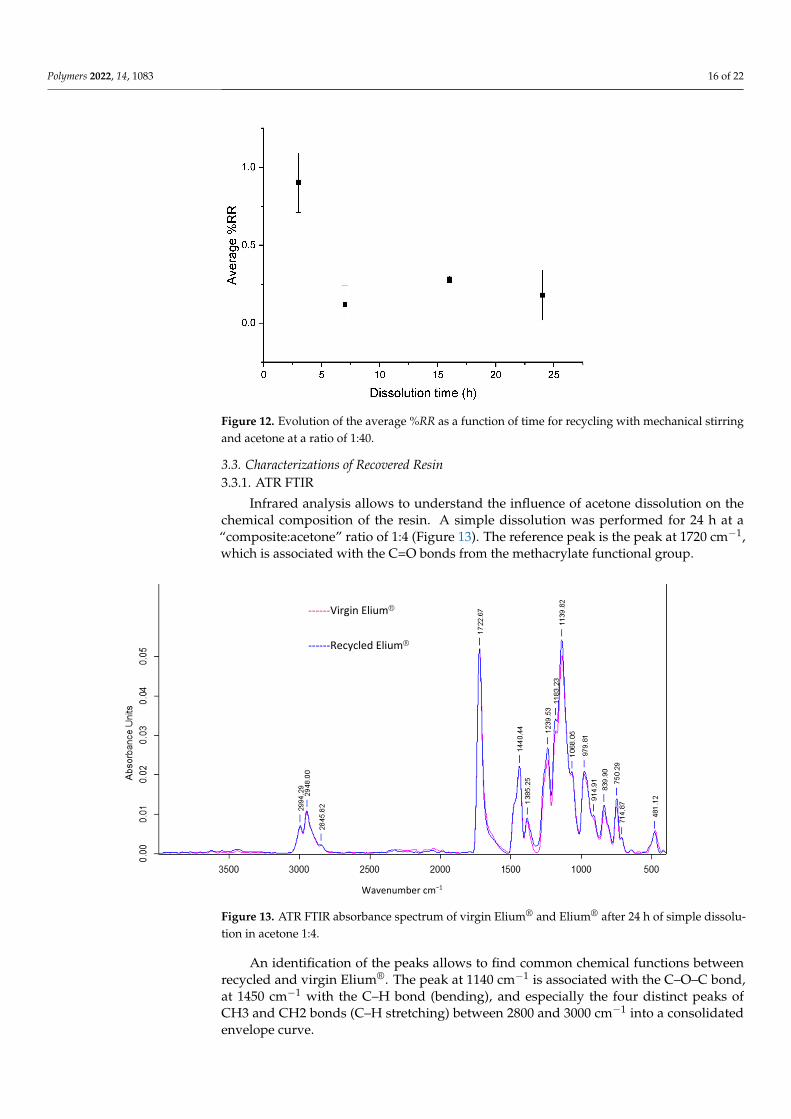
In the case of recycling with mechanical stirring, a very small amount of resin is onthe fibers, even at 3 h of recycling (Figure 12), which is confirmed by SEM analysis.
Polymers 2022, 14, 1083 16 of 22
Figure 12. Evolution of the average %RR as a function of time for recycling with mechanical stirringand acetone at a ratio of 1:40.
3.3. Characterizations of Recovered Resin3.3.1. ATR FTIR
Infrared analysis allows to understand the influence of acetone dissolution on thechemical composition of the resin. A simple dissolution was performed for 24 h at a“composite:acetone” ratio of 1:4 (Figure 13). The reference peak is the peak at 1720 cm−1,which is associated with the C=O bonds from the methacrylate functional group.
Polymers 2022, 14, x FOR PEER REVIEW 16 of 22
Figure 12. Evolution of the average %RR as a function of time for recycling with mechanical stirring and acetone at a ratio of 1:40.
3.3. Characterizations of Recovered Resin 3.3.1. ATR FTIR
Infrared analysis allows to understand the influence of acetone dissolution on the chemical composition of the resin. A simple dissolution was performed for 24 h at a “com-posite:acetone” ratio of 1:4 (Figure 13). The reference peak is the peak at 1720 cm−1, which is associated with the C=O bonds from the methacrylate functional group.
Figure 13. ATR FTIR absorbance spectrum of virgin Elium® and Elium® after 24 h of simple disso-lution in acetone 1:4.
An identification of the peaks allows to find common chemical functions between recycled and virgin Elium®. The peak at 1140 cm−1 is associated with the C–O–C bond, at 1450 cm−1 with the C–H bond (bending), and especially the four distinct peaks of CH3 and
0 5 10 15 20 25
0,0
0,5
1,0
Aver
age
%R
R
Dissolution time (h)
------Virgin Elium®
------Recycled Elium®
Wavenumber cm−1
Figure 13. ATR FTIR absorbance spectrum of virgin Elium® and Elium® after 24 h of simple dissolu-tion in acetone 1:4.
An identification of the peaks allows to find common chemical functions betweenrecycled and virgin Elium®. The peak at 1140 cm−1 is associated with the C–O–C bond,at 1450 cm−1 with the C–H bond (bending), and especially the four distinct peaks ofCH3 and CH2 bonds (C–H stretching) between 2800 and 3000 cm−1 into a consolidatedenvelope curve.
Polymers 2022, 14, 1083 17 of 22
It can be observed that the three peaks at 1361 cm−1, 911 cm−1, and 715 cm−1 havedisappeared in the spectrum of the recycled Elium®. The first peak is attributed to C–HCsp3 bonds and the second to C–H Csp2 bonds. Otherwise, the other peaks in the twospectra merge. In addition, small chains, monomer residues, and some additives such ascitral can probably exfoliate and migrate out of the polymer. In conclusion, the chemicalcomposition of Elium® recovered after acetone dissolution is close to that of virgin Elium®.
3.3.2. SEC
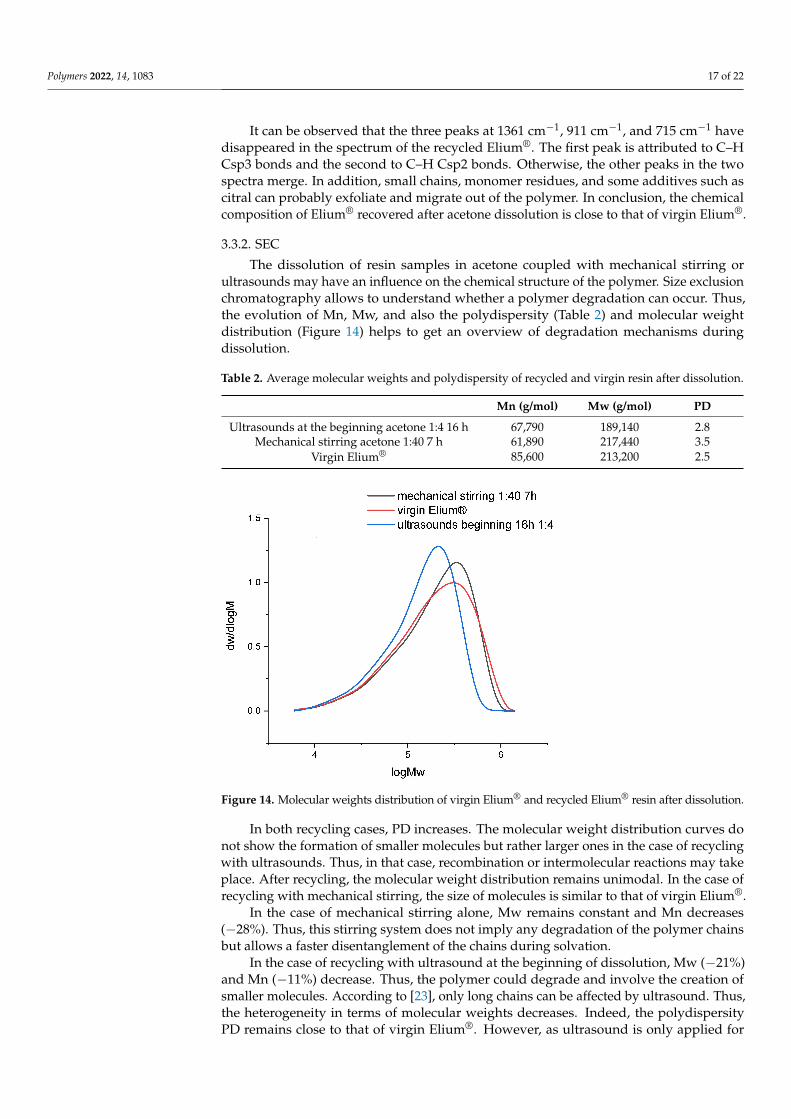
The dissolution of resin samples in acetone coupled with mechanical stirring orultrasounds may have an influence on the chemical structure of the polymer. Size exclusionchromatography allows to understand whether a polymer degradation can occur. Thus,the evolution of Mn, Mw, and also the polydispersity (Table 2) and molecular weightdistribution (Figure 14) helps to get an overview of degradation mechanisms duringdissolution.
Table 2. Average molecular weights and polydispersity of recycled and virgin resin after dissolution.
Mn (g/mol) Mw (g/mol) PD
Ultrasounds at the beginning acetone 1:4 16 h 67,790 189,140 2.8Mechanical stirring acetone 1:40 7 h 61,890 217,440 3.5
Virgin Elium® 85,600 213,200 2.5
Figure 14. Molecular weights distribution of virgin Elium® and recycled Elium® resin after dissolution.
In both recycling cases, PD increases. The molecular weight distribution curves donot show the formation of smaller molecules but rather larger ones in the case of recyclingwith ultrasounds. Thus, in that case, recombination or intermolecular reactions may takeplace. After recycling, the molecular weight distribution remains unimodal. In the case ofrecycling with mechanical stirring, the size of molecules is similar to that of virgin Elium®.
In the case of mechanical stirring alone, Mw remains constant and Mn decreases(−28%). Thus, this stirring system does not imply any degradation of the polymer chainsbut allows a faster disentanglement of the chains during solvation.
In the case of recycling with ultrasound at the beginning of dissolution, Mw (−21%)and Mn (−11%) decrease. Thus, the polymer could degrade and involve the creation ofsmaller molecules. According to [23], only long chains can be affected by ultrasound. Thus,the heterogeneity in terms of molecular weights decreases. Indeed, the polydispersityPD remains close to that of virgin Elium®. However, as ultrasound is only applied for
Polymers 2022, 14, 1083 18 of 22
3 min at the beginning of dissolution, it is not sufficient to really create a degradation.Recombination of molecules can also be at the origin of the formation of larger molecules.
3.4. Mechanical Properties of Second-Generation Composites3.4.1. Static Tensile Tests
Mechanical results of uniaxial tensile tests performed on Elium®/basalt compositesare reported in Table 3. The pore volume of the composites was also measured and arepresented in Table 3.
Table 3. Modulus, tensile strength, and porosity of first and second generation Elium®/basaltcomposites recycled using mechanical stirring and ultrasounds at the beginning of the dissolution.
Modulus (GPa) Stress (MPa) Porosity (%) Fiber Weight Fraction (%)
1st generation 19.9 ± 2.7 508.0 ± 34.8 8.6 ± 5.9 71.4 ± 1.02nd generation:mechanical stirring 24.4 ± 4.7 586.8 ± 22.1 4.2 ± 2.7 71.4 ± 0.4
2nd generation: ultrasoundsat beginning 20.6 ± 2.4 474.3 ± 24.5 2.9 ± 2.0 67.1 ± 0.8
Second generation composites after a dissolution process using mechanical stirringhave a 22% higher modulus (24.4 ± 4.7 GPa against 19.9 ± 2.7 GPa in the initial state) anda 15% higher stress (586.8 ± 22.1 MPa against 508 ± 34.8 MPa). After a dissolution processusing ultrasound, second generation composites have tensile properties comparable to firstgeneration composites with a modulus (−3%) of 20.6 ± 2.4 GPa against 19.9 ± 2.7 GPa anda stress of 474.3 ± 24.5 MPa against 508.0 ± 34.8 MPa (−6%). The lower fabric degradationafter dissolution process using mechanical stirring (Figure 6) compared to those usingultrasound (Figure 5) may explain the better performance in tensile tests.
However, for dissolution conditions, the porosity is lower than for first generationcomposites, −51% for mechanical stirring despite an equal fiber weight ratio ∼= 71.4%.Nevertheless, composites from ultrasounds have less than −66% of porosity with a fiberweight fraction much lower (67.1 ± 0.8%). In addition, despite a higher porosity rate(4.2% by mechanical stirring vs. 2.9% by ultrasounds), the composite recycled by mechanicalstirring has superior tensile performance (+15% in modulus and +19% in stress), comparedto the composite recycled by ultrasounds.
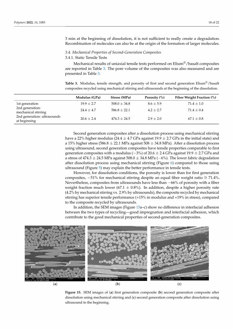
In addition, the SEM images (Figure 15a–c) show no difference in interfacial adhesionbetween the two types of recycling—good impregnation and interfacial adhesion, whichcontribute to the good mechanical properties of second-generation composites.
Polymers 2022, 14, x FOR PEER REVIEW 19 of 22
(a) (b) (c)
Figure 15. SEM images of (a) first generation composite (b) second generation composite after dis-solution using mechanical stirring and (c) second generation composite after dissolution using ul-trasound in the beginning.
3.4.2. Dynamic Mechanical Analysis The tests were carried out on first- and second-generation composites (Figure 16). For
the latter, the dissolution was performed using ultrasound for 3 min in the beginning for 16 h (ratio 1:4) and mechanical stirring for 7 h (ratio 1:40). Table 4 is a summary of the data measured from the DMA tests, where E’160 and E’40 are the rubber and vitreous conser-vation modules, respectively.
(a)
20 40 60 80 100 120 140 160 180 200
0,0
0,1
0,2
0,3
0,4
0,5
Tan
delta
T (°C)
1st generation Ultrasounds Mechanical stirring
Damping factor comparison
Figure 15. SEM images of (a) first generation composite (b) second generation composite afterdissolution using mechanical stirring and (c) second generation composite after dissolution usingultrasound in the beginning.
Polymers 2022, 14, 1083 19 of 22
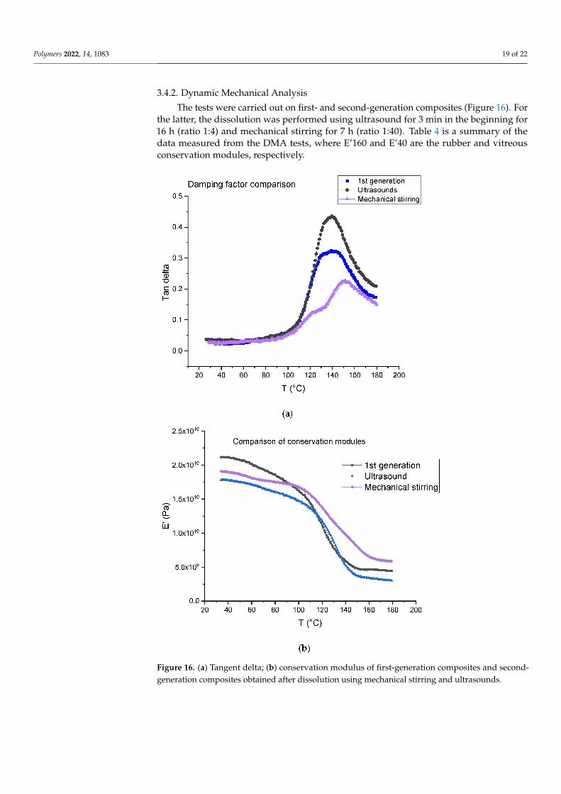
3.4.2. Dynamic Mechanical Analysis
The tests were carried out on first- and second-generation composites (Figure 16). Forthe latter, the dissolution was performed using ultrasound for 3 min in the beginning for16 h (ratio 1:4) and mechanical stirring for 7 h (ratio 1:40). Table 4 is a summary of thedata measured from the DMA tests, where E’160 and E’40 are the rubber and vitreousconservation modules, respectively.
Figure 16. (a) Tangent delta; (b) conservation modulus of first-generation composites and second-generation composites obtained after dissolution using mechanical stirring and ultrasounds.

Polymers 2022, 14, 1083 20 of 22
Table 4. DMA results of first generation composites and those recycled by mechanical stirringand ultrasound.
1st Generation 2nd GenerationMechanical Stirring
2nd Generation:Ultrasounds
E’40 (GPa) 19.87 ± 1.87 18.99 ± 0.27 16.25 ± 1.18E’160 (GPa) 4.25 ± 0.69 6.30 ± 0.35 3.03 ± 0.20
tan d1 / 0.13 ± 0.01 /T1 (◦C) / 122.30 ± 1.45 /tan dα 0.32 ± 0.01 0.21 ± 0.02 0.40 ± 0.03Tα (◦C) 139.27 ± 2.12 151.11 ± 1.16 138.81 ± 4.97
The first generation composite shows a main relaxation peak related to glass transitiontemperature located at about 139 ◦C with an intensity of 0.32 At the same time, the modulusdrops from 19.87 ± 1.87 GPa to 4.25 ± 0.69 GPa.
In the case of a dissolution using mechanical stirring, second generation compositesprovide evidence of a shoulder on the main relaxation peak located at 122 ◦C, i.e., at a lowertemperature (151 ◦C) than the main relaxation. The intensity of both peaks is 0.13 (shoulder)and 0.21 (main peak). In the case of a dissolution using ultrasounds, no shoulder is observedand the main relaxation is located at about 139 ◦C as for the first-generation composites.Nevertheless, a higher intensity is determined (0.40). As concerns storage modulus, itdrops from 18.99 ± 0.27 GPa to 6.30 ± 0.3 GPa when mechanical stirring is used and from16.25 ± 1.18 GPa to 3.03 ± 0.20 when ultrasounds are used. First, it can be concluded thatthe storage modulus at 40 ◦C is not affected by recycling and corresponds to the same orderthan the first-generation composites.
Differences may be explained by the presence of residual resin on the fabrics afterresin dissolution. This resin may form a thin homogeneous layer when mechanical stir-ring is used, as it seems to be a more heterogeneous cluster when ultrasounds are used(Figure 10), even if the residual resin rate is higher in the case of ultrasonic recycling incomparison with the mechanical method. Further investigation will be carried out toconfirm this assumption.
4. Conclusions
The objective of this work was to compare the material recoveries resulting fromdifferent chemical recycling methodologies for thermoplastic acrylate-based compositesreinforced by basalt fabrics and manufactured by vacuum infusion. The recycling was pro-cessed via chemical dissolution with a preselected adapted solvent i.e., acetone. The maingoal of the study was to recover undamaged basalt fabrics to reuse them as reinforcementsfor second generation composites.
A protocol based on an ultrasound technique was compared to another one using me-chanical stirring. The results show that the dissolution protocol using a mechanical stirringis more adapted to recover undamaged fabrics with no residual resin on their surface.
Several parameters, such as dissolution duration, dissolution temperature, and sol-vent/composite ratio were also studied. The results show that in the case of a 1:40 ratio, theoptimal dissolution time required for total dissolution of the resin is about 7 h. Moreover,the higher the solvent volume, the higher the dissolution rate.
FTIR and SEC analysis show that there is no degradation of the resin after dissolutionby acetone, but recombination phenomena do not modify the chemical composition of theElium® resin. The stirring system allows disentanglement of long polymer chains, and thishas a low impact on the molecular mass distribution.
Finally, second generation composites were elaborated with these recycled fabrics andmechanical and thermomechanical properties were determined and compared to thoseof first-generation composites. Corresponding second generation composites displayedequivalent mechanical properties than first generation ones.
Polymers 2022, 14, 1083 21 of 22
Heating was avoided in this study for lower energy consumption and lower safetyrisks, but it should be interesting to evaluate the effect of temperature. As the protocolwith mechanical agitation requires a larger amount of solvent (50 mL of acetone for 1 gof composite), whereas the protocol with ultrasound can be limited to 5 mL of solventfor 1 g of composite, an up-scale study should be performed. Greener solvent should beconsidered in further investigations.
Author Contributions: Conceptualization, I.M.z.R., A.S., A.B., C.L., D.P., K.M. and A.O.; methodol-ogy, I.M.z.R., A.S., A.B., C.L., D.P., K.M. and A.O.; software, I.M.z.R. and A.S.; validation, A.B., C.L.,D.P., K.M. and A.O.; formal analysis, I.M.z.R. and A.S.; investigation, I.M.z.R.; resources, I.M.z.R. andA.S.; data curation, I.M.z.R. and A.S.; writing—original draft preparation, I.M.z.R. and A.S.; writing—review and editing, A.B., C.L., D.P., K.M. and A.O.; visualization, I.M.z.R. and A.S.; supervision, A.B.,C.L., D.P., K.M. and A.O.; project administration, D.P.; funding acquisition, K.M. All authors haveread and agreed to the published version of the manuscript.
Funding: This research received no external funding.
Institutional Review Board Statement: Not applicable.
Informed Consent Statement: Not applicable.
Data Availability Statement: Data cannot be shared, as it is a part of an ongoing study.
Acknowledgments: The authors would like to acknowledge Segula Technologies and NationalAssociation of Research and Technology (ANRT) for the financial support. They would also like tothank Arkema for the supply of Elium® resin. The authors also thank Caroline Chaix of the CharlesGerhardt Institute of Montpellier of the University of Montpellier for carrying out the SEC tests. Theauthors thank Guillaume Ienny at CM2A of IMT mines Alès for their expertise on infusion.
Conflicts of Interest: The authors declare no conflict of interest.
References1. JEC Composites. Available online: https://www.jeccomposites.com/press/le-jec-observer-une-vision-globale-du-marche-des-
composites/ (accessed on 11 October 2021).2. EUR-Lex. Available online: https://eur-lex.europa.eu/legal-content/EN/TXT/?uri=CELEX%3A02019R0631-20211202 (accessed
on 27 December 2021).3. Komornicki, J.; Bax, L.; Vasiliadis, H.; Ong, K. Polymer composites for automotive sustainability. Innov. Manager SusChem
Secr. 2015.4. Marmol, G.; Ferreira, D.P.; Fangueiro, R. 24—Automotive and construction applications of fiber reinforced composites. In
Woodhead Publishing Series in Composites Science and Engineering, Fiber Reinforced Composites; Joseph, K., Oksman, K., George, G.,Wilson, R., Appukuttan, S., Eds.; Woodhead Publishing: Sawston, UK, 2021; pp. 785–819.
5. Fiore, V.; Scalici, T.; Di Bella, G.; Valenza, A. A review on basalt fiber and its composites. Compos. Part B 2015, 74, 74–94. [CrossRef]6. Galindo, B.; Ruiz, R.; Ulldemolins, G.; Losada, C. Development of long fiber thermoplastic composites for industrial applications.
Reinf. Plast. 2021. [CrossRef]7. Balaji, K.V.; Shirvanimoghaddam, K.; Rajan, G.S.; Ellis, A.V.; Naebe, M. Surface treatment of Basalt fiber for use in automotive
composites. Mater. Today Chem. 2020, 17, 100334.8. Mallick, P.K. 5—Thermoplastics and thermoplastic–matrix composites for lightweight automotive structures. In Woodhead
Publishing Series in Composites Science and Engineering, Materials, Design and Manufacturing for Lightweight Vehicles; Mallick, P.K.,Ed.; Elsevier: Amsterdam, The Netherlands, 2010; pp. 174–207.
9. Gaumond, B. Compréhension des Interfaces/Interphases Formées dans les Composites PPS/Fibres de Carbone et PPS/Fibres deBasalte Réalisés à Partir de Mèches Comélées et Retordues. Matériaux. Ph.D. Thesis, Université de Lyon, Lyon, France, 2020.
10. Oliveux, G.; Dandy, L.O.; Leeke, G.A. Current status of recycling of fibre reinforced polymers: Review of technologies, reuse andresulting properties. Prog. Mater. Sci. 2015, 72, 61–99. [CrossRef]
11. Evchuk, I.Y.; Musii, R.I.; Makitra, R.G.; Pristanskii, R.E. Solubility of Polymethyl Methacrylate in Organic Solvents. Russ. J. Appl.Chem. 2005, 78, 1576–1580. [CrossRef]
12. Tschentscher, C.; Gebhardt, M.; Chakraborty, S.; Meiners, D. Recycling of Elium CFRPs for high temperature dissolution: A studywith different solvents. In Proceedings of the Symposium Materialtechnik, Clausthal-Zellerfeld, Germany, 25–26 February 2021.
13. Gebhardt, M.; Chakraborty, S.; Manolakis, I.; Meiners, D. Recycling of CFRP composites based on a thermoplastic matrix(Elium 150) which can be infused and cured at room temperature—Recovery of the matrix by dissolution processes and testing offibre damage by means of SEM and single fibre tensile tests. In Proceedings of the Forschungsfeldkolloquium 2020 ForschungsfeldRohstoffsicherung und Ressourceneffizienz, Clausthal-Zellerfeld, Germany, June 2020.
Polymers 2022, 14, 1083 22 of 22
14. Adherent-Technologies. Available online: http://www.adherent-tech.com/recycling_technologies (accessed on 12 January 2022).15. Gosau, J.-M.; Wesley, T.F.; Allred, R. Integrated Composite Recycling Process. In Proceedings of the 38th SAMPE Technical
Conference, Dallas, TX, USA, 7–9 November 2006.16. Morin, C.; Loppinet-Serani, A.; Cansell, F.; Aymonier, C. Near- and supercritical solvolysis of carbon fibre reinforced polymers
(CFRPs) for recycling carbon fibres as a valuable resource: State of the art. J. Supercrit. Fluids 2012, 66, 232–240. [CrossRef]17. Baudu, C. Device for Treating a Solid Composite Material by Solvolysis with a View to Extracting Fibres from the Treated Material,
Issued 16 October 2014. Available online: https://patentscope.wipo.int/search/en/detail.jsf?docId=WO2014166962 (accessed on20 June 2021).
18. Nakagawa, T.; Itoh, T.; Hidaka, M.; Urabe, T.; Yoshimura, T. Enhanced and Horizontal Recycling Technology of FRP UsingSub-Critical Water. J. Netw. Polym. 2008, 29, 158–165.
19. Das, M.; Varughese, S. A Novel Sonochemical Approach for Enhanced Recovery of Carbon Fiber from CFRP Waste Using MildAcid–Peroxide Mixture. ACS Sustain. Chem. Eng. 2016, 4, 2080–2087. [CrossRef]
20. Desai, V.; Shenoy, M.A.; Gogate, P.R. Degradation of polypropylene using ultrasound-induced acoustic cavitation. Chem. Eng. J.2008, 140, 483–487. [CrossRef]
21. Daraboina, N.; Madras, G. Kinetics of the ultrasonic degradation of poly (alkyl methacrylates). Ultrason. Sonochemistry 2009, 16,273–279. [CrossRef] [PubMed]
22. Yan, J.K.; Pei, J.J.; Ma, H.L.; Wang, Z.B. Effects of ultrasound on molecular properties, structure, chain conformation anddegradation kinetics of carboxylic curdlan. Carbohydr. Polym. 2015, 121, 64–70. [CrossRef] [PubMed]
23. Miller-Chou, B.A.; Koenig, J.L. A review of polymer dissolution. Prog. Polym. Sci. 2003, 28, 1223–1270. [CrossRef]
Related Documents