1 CHAPTER ONE INTRODUCTION 1.1 General Concept Radio Frequency (RF) controlled spy robot is an exclusive project where the direction of the movement of robot can be changed using wireless technologies. The robot will be placed different from that of from where it is controlled. The robot movement is controlled using wireless concept, the controlling of the Robot is done from the transmitter and this information will be passed to the Robot in a wireless fashion, there are several wireless technologies to accomplish this task. The protocol used in this project is RF technology. To control the direction of the Robot, predefined keys has to given as commands from the transmitter section. The data from the transmitter section is transmitted and will be received by microcontroller at the receiver section. The data, while before being transmitted, will be converted into a format suitable for transmission. i.e., data will be encoded. At the receiving end, the receiver section receives this data. The data received will be decoded being before given to the microcontroller for further processing. Now, it is the job of the controller to read the data and perform the corresponding action i.e., move the robot in that particular direction based on the command received from the transmitter end. The microcontroller at the receiver end continuously receives the video signal from a wireless camera which is attached to the robot and this robot is used to capture the video of the criminal and observe their position remotely in a Personal Computer (PC). 1.2 Problem Statement The intention of this project is to reduce human victims in terrorist attack. So this problem can be overcome by designing the RF based spy robot which involves wireless camera, so that from this we can examine rivals when it

Welcome message from author
This document is posted to help you gain knowledge. Please leave a comment to let me know what you think about it! Share it to your friends and learn new things together.
Transcript

1
CHAPTER ONE
INTRODUCTION
1.1 General Concept
Radio Frequency (RF) controlled spy robot is an exclusive project where
the direction of the movement of robot can be changed using wireless
technologies. The robot will be placed different from that of from where it is
controlled. The robot movement is controlled using wireless concept, the
controlling of the Robot is done from the transmitter and this information will be
passed to the Robot in a wireless fashion, there are several wireless technologies
to accomplish this task. The protocol used in this project is RF technology.
To control the direction of the Robot, predefined keys has to given as
commands from the transmitter section. The data from the transmitter section is
transmitted and will be received by microcontroller at the receiver section. The
data, while before being transmitted, will be converted into a format suitable for
transmission. i.e., data will be encoded.
At the receiving end, the receiver section receives this data. The data
received will be decoded being before given to the microcontroller for further
processing. Now, it is the job of the controller to read the data and perform the
corresponding action i.e., move the robot in that particular direction based on the
command received from the transmitter end. The microcontroller at the receiver
end continuously receives the video signal from a wireless camera which is
attached to the robot and this robot is used to capture the video of the criminal
and observe their position remotely in a Personal Computer (PC).
1.2 Problem Statement
The intention of this project is to reduce human victims in terrorist attack.
So this problem can be overcome by designing the RF based spy robot which
involves wireless camera, so that from this we can examine rivals when it

2
required. This robot can quietly enter into enemy area and sends us the
information via wireless camera.
The movement of this robot is wirelessly controlled by an android phone,
Since human life is always valuable, these robots are the substitution of soldiers
in war areas. This spy robot can also be used in star hotels, shopping malls,
jewelry show rooms, etc where there can be threat from intruders or terrorists.
1.3 Objectives - Designing of android phone controlled robot,
- Gathering information by using wireless camera mounted on the robot.
1.4Methodology To achieve the objectives of the proposed project, the project is divided to
small tasks as follow:
- Study of all previous related work.(literature review)
- Build a simulation of the system using Protues schematic professional.
- Design the system based on the gathered requirements and specifications.
1.5 Layout This project consists of five chapters. Chapter one presents general
concept, problem statement, objectives, methodology and layout. Chapter two
shows a theoretical background of the spy robot. Chapter three includes the
hardware of the project’s model. Chapter four shows the simulation and result,
finally Chapter five include the conclusion and recommendations.

3
CHAPTER TWO
BACKGROUND AND LITERATURE
REVIEW
2.1 Introduction Robots are smart machines that can be programmed and used in many
areas such as industry, manufacturing, production lines, or health, etc [1]. These
robots perform hard, dangerous, and accurate work to facilitate our life and to
increase the production because they can work 24 hours without rest , and can do
works like human but more precisely and with less time. Assistive mobile robots
that perform different kinds of work over everyday activities in many areas such
as industry, manufacturing, production lines, or health, etc. are very commonly
used to improve our life. The idea of this research is to exploit robotics usage on
healthcare field to help mobility disabled people.
The design of this project encourages developing a robotic vehicle based
on RF technology for the remote operation connected with the wireless camera
mounted on the robot for monitoring purpose. The robot is embedded with
Arduino microcontroller for desired operation and is generally used for spying
purposes. The transmitting module consist of a Smartphone send the commands
by transmitting AT commands and data to the Arduino microcontroller to control
the DC motors by motor shield driver L923D. The robot motions left, right,
forward, backward. Interfacing is being done between device and Bluetooth.
Bluetooth device HC-05 module receives the commands from smart phone via
Arduino microcontroller. The wireless camera used for spying purpose also
serves in complete darkness using (Infrared Radiation) IR lightning.
2.2 Microcontroller
It is a highly integrated chip that contains all the components comprising a
controller. Typically this includes a (Central Process Unit) CPU, both (Random
Access Memory) RAM, (Read Only Memory) ROM and (Input/ Output) I/O

4
ports. Unlike a general-purpose computer, which also includes all of these
components, a microcontroller is designed for a very specific task to control a
particular system. As a result, the parts can be simplified and reduced, which
cuts down on production cost.
2.2.1 History of microcontroller
The first computer system on a chip optimized for control applications was the
Intel 8048microcontroller with RAM and ROM on the same chip. Most
microcontrollers at that time had two variants, one had an erasable (Electrically
Erasable Programmable Read Only Memory) EEPROM program memory,
which was significantly more expensive than the PROM variant which was only
programmable once.
The introduction of EEPROM memory allowed microcontrollers
(beginning with the MicrochipPIC16x84) to be electrically erased quickly
without an expensive package as required for (Erasable Programmable Read
Only Memory) EPROM. The same year, Atmel introduced the first microcon-
troller using Flash memory. Other companies rapidly followed suit, with both
memory types. Nowadays microcontrollers are low cost and readily available for
hobbyists, with large online communities around certain processors. A
microcontroller is a single-chip computer .Micro suggests that the device is
small, and controller suggests that it is used in control applications. Another term
for microcontroller is embedded controller, since most of the microcontrollers
are built into (or embedded in) the devices that controlling.
Microcontrollers have traditionally been programmed using the assembly
language of the target device. Although the assembly language is fast, it has
several disadvantages. An assembly program consists of mnemonics, which
makes learning and maintaining a program written using the assembly language
difficult. Also, microcontrollers manufactured by different firms have different

5
assembly languages, so the user must learn a new language with every new
microcontroller he or she uses.
Microcontrollers can also be programmed using a high-level language,
such as BASIC, PASCAL, or C. High-level languages are much easier to learn
than assembly languages and also facilitate the development of large and
complex programs [2].
2.2.2 Components of a microcontroller Microcontrollers combine the fundamental resources available in a
microcomputer such as the (CPU), memory, and Input/output resources in a
single chip. Figure 2.1 shows the block diagram for a generic microcontroller.
Microcontroller has an oscillator to generate the signal necessary to synchronize
all internal operations. Although this can be a basic Resistance Capacitor (RC)
oscillator, a quartz crystal (XTAL) is normally used due to its high frequency
stability. The frequency of the oscillator has a direct influence on the speed at
which program instructions are executed.
Figure 2.1: Components of microcontroller
• Central processing unit
Similar to microcomputers, the Central processing unit (CPU) is the brain
of the microcontroller. The CPU fetches the program instructions from their
locations in memory one by one, interprets or decodes them, and executes them.

6
The CPU also includes the Arithmetic and Logic Unit (ALU) circuits for binary
arithmetic and logic operations. The microcontroller’s CPU has different
registers.
Some of these registers are intended for general use, whereas others have a
specific purpose. Specific purpose registers include: instruction register,
accumulator, status register, program counter, data address register, and stack
pointer. The Instruction Register (IR) stores the instruction that the CPU is
executing. The programmer does not normally have access to the IR. The
Accumulator (ACC) is a register associated with the arithmetic and logic
operations that the ALU is carrying out. When executing any operation, one of
the data needs to be in the ACC. The resulting value is also stored in the ACC.
PIC microcontrollers do not have the ACC register. Instead, they have a working
register that is very similar to the ACC. The status register (STATUS) contains
the bits that show different characteristics [3].
• Memory
Any microcontroller has two types of memory: Random-Access Memory
(RAM) and Read -Only Memory (ROM). RAM can be read and written. RAM is
volatile memory, meaning that its data is lost when it is not powered. On the
other hand, although ROM can only be read, it is non-volatile. The different
types of technologies used for ROM such as Erasable Programmable Read-Only
Memory(EPROM), Electrical Erasable Programmable Read-Only
Memory(EEPROM), One-Time Programmable(OTP), both RAM and ROM are
“random access” memories, meaning that the time to access specific data does
not depend on its stored location. This is opposed to sequential access memories
in which the time needed to access a specific memory cell depends on the
location of the last accessed cell. ROM is used to permanently store the program
for the microcontroller; Whereas RAM is used to temporarily store the data that
will be manipulated by the program. An increasing number of microcontrollers
7
use nonvolatile memory such as EEPROM to store some of the data that is
changed only sporadically. The size of ROM is larger than the size of RAM for
two main reasons: First, most applications require programs that manipulate a
relatively small number of data. Second, RAM has a larger footprint compared to
ROM, and therefore it is more expensive than ROM [4].
• Interrupts
Interrupts are an important concept in microcontrollers. An interrupt
causes the microcontroller to respond to external and internal (e.g., a timer)
events very quickly. When an interrupt occurs, the microcontroller leaves its
normal flow of program execution and jumps to a special part of the program
known as the Interrupt Service Routine (ISR). The program code inside the ISR
is executed, and upon return from the ISR the program resumes its normal flow
of execution. The ISR starts from a fixed address of the program memory
sometimes known as the interrupt vector address. Some microcontrollers with
multi-interrupt features have just one interrupt vector address, while others have
unique interrupt vector addresses, one for each interrupt source. Interrupts can be
nested such that a new interrupt can suspend the execution of another interrupt.
Another important feature of multi-interrupt capability is that different interrupt
sources can be assigned different levels of priority [4].
• Timers
Timers are important parts of any microcontroller. A timer is basically a
counter which is driven from either an external clock pulse or the
microcontroller’s internal oscillator. A timer can be 8 bits or 16 bits wide. Data
can be loaded into a timer under program control, and the timer can be stopped
or started by program control. Most timers can be configured to generate an
interrupt when they reach a certain count (usually when they overflow). The user
program can use an interrupt to carry out accurate timing-related operations
inside the microcontroller [5].

8
• Input /Output resource
Input/output (I/O) resources consist of the serial and parallel ports, timers,
and interruption managers. Some microcontrollers also incorporate analog input
and output lines associated with Analog-to-Digital (A/D) and Digital-to-Analog
(D/A) converters. The resources needed to ensure the regular operation of the
microcontrollers such as the watchdog are also considered part of the I/O
resource. Parallel ports are normally structured in groups of up to eight lines of
digital inputs and outputs. It is normally possible to manipulate each one of these
lines individually.
Serial ports can be of different technologies such as RS-232C
(Recommended Standard 232, Revision C), I2C (inter-integrated circuit),
Universal Serial Bus (USB), and Ethernet. In general, a microcontroller will
have the largest possible number of I/O resources for the number of available
pins in its integrated circuit package. To increase the performance, one physical
pin can be connected to several internal blocks, and therefore that pin may carry
out different functions depending on how the microcontroller has been
configured [5].
• The watchdog
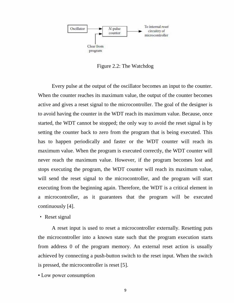
The Watch Dog Timer (WDT) is a resource that can be found in most
microcontrollers. As shown in Figure (2.3) the WDT consists of an oscillator and
a binary counter of N bits. Although the oscillator can be the same oscillator
used by the microcontroller, it is preferable to use an independent oscillator. The
output of the counter is connected to the reset input for the microcontroller. The
counting process can never be stopped, although the program being executed can
periodically reset the counter to its initial value.
9
Figure 2.2: The Watchdog
Every pulse at the output of the oscillator becomes an input to the counter.
When the counter reaches its maximum value, the output of the counter becomes
active and gives a reset signal to the microcontroller. The goal of the designer is
to avoid having the counter in the WDT reach its maximum value. Because, once
started, the WDT cannot be stopped; the only way to avoid the reset signal is by
setting the counter back to zero from the program that is being executed. This
has to happen periodically and faster or the WDT counter will reach its
maximum value. When the program is executed correctly, the WDT counter will
never reach the maximum value. However, if the program becomes lost and
stops executing the program, the WDT counter will reach its maximum value,
will send the reset signal to the microcontroller, and the program will start
executing from the beginning again. Therefore, the WDT is a critical element in
a microcontroller, as it guarantees that the program will be executed
continuously [4].
Reset signal
A reset input is used to reset a microcontroller externally. Resetting puts
the microcontroller into a known state such that the program execution starts
from address 0 of the program memory. An external reset action is usually
achieved by connecting a push-button switch to the reset input. When the switch
is pressed, the microcontroller is reset [5].
• Low power consumption

10
Because batteries power most applications using microcontrollers, power
consumption has become a critical parameter. Power consumption in an
integrated circuit depends on three factors: the technology used in the chip, the
frequency of its oscillator, and the value of its voltage supply. Complementary
Metal-Oxide Semiconductor (CMOS) is the preferred technology for
manufacturing microcontrollers due its low power needs. In static conditions
only a very small leakage current flows through the gates. Its power consumption
is only significant when switching logic states. Increasing the frequency of the
oscillator increases the number of switching actions, and therefore its power
consumption also increases.
However, it is important to remember that in many applications the
microcontroller is just waiting for an external event, such as a key being pressed,
or an interrupt, before carrying out a task. Once finished, it returns to the waiting
state. To further decrease its power consumption, it is a good idea to paralyze the
microcontroller either totally or partially while it is waiting for an external event.
The best method to paralyze the microcontroller is to stop its main oscillator.
This will force the main systems to be in a static mode waiting for an external
action to start it again. When this happens, the microcontroller is said to be in
idle state, power down, or sleep mode. Different microcontrollers have different
methods to enter this low-power state. Some microcontrollers only need to
modify a determined bit from a specific register, whereas other microcontrollers
have a dedicated instruction for this purpose. The only way to leave this low-
power mode is by means of an external Interrupt or by a reset [3].
2.2.4 Applications of microcontroller
In addition to control applications such as the home monitoring system,
micro controllers are frequently found in embedded applications. Among the
many applications that could be find one or more microcontrollers: automotive
applications, appliances, automobiles, environmental control, instrumentation,

11
and thousands of other uses. Microcontrollers are used extensively in robotics. In
this application, many specific tasks might be distributed among a large number
of microcontrollers in one system. Communications between each
microcontroller and central, more powerful microcontroller would enable
information to be processed by the central computer, or to be passed around to
other microcontrollers in the system. A special application that microcontrollers
are well suited for is data logging. Stick one of these chips out in the middle of a
corn field or up in a balloon, and monitor and record environmental parameters
(temperature, humidity, rain, etc.). Small size, low power consumption, and
flexibility make these devices ideal for unattended data monitoring and recording
[3].
2.3 DC Motor The DC motor is the simplest and the earliest electrical motor design. The
DC motor consists of a few simple components: stationary stator composed of
field coils or two hemispherical permanent magnets (PM). An internal rotating
armature consisting of two or more coils connected to a segmented commutator
which is contacted by brushes connected to the DC power supply as shown in
figure 2.3. DC power is conducted through the brushes and commutator and the
current through the coil creates a magnetic field. This field is opposite to the
magnetic field of the permanent magnets in the stator, causing the armature to
rotate. With a two-pole motor the commutator causes the current to reverse in
direction every half cycle, causing the motor to continue to rotate. The speed of
the motor is directly proportional to the voltage applied, while the torque is
proportional to the current. You control the speed of a DC motor by simply
varying the voltage applied to it; to reverse it, just reverse the polarity of the
applied voltage; and to stop it turn off the voltage.
DC motors have some advantages over other designs:
- They are simple and inexpensive.

12
-They don’t require complex drive electronics.
-Their speed is a direct, linear function of the armature voltage.
Figure 2.3 Permanent magnet DC motor
DC-motors are very easy to use, but like most other motors their
usefulness for robotics is very dependent on the gearing available. DC-motors
are made much more effective if they have an efficient gear ratio for a particular
task. The most motors used in robots need torque over top speed so a motor with
a high gear ratio could be more useful. The control of a DC motor can be split
into two parts: speed and direction.
Direction
Changing which direction a DC-motor turns is very simple: simply reverse
the polarity. Both pairs of switches (S1A, S1B) and (S2A, S2B) will always
switch together. This circuit is called an H-bridge. In a real design the switches
can be several different components (Relays, transistors) or the whole circuit
(without the motor) could be an (Integrated Circuit) IC as shown in Figure 2.4.
Speed
Controlling the motor speed by reducing its voltage with a variable
resistor or other ways does not work well, because it will not only reduce the
motor's speed, it will also reduce a motor's strength, while also consuming a lot
of electricity as large amounts of heat are generated by the resistor.

13
A far better way is to use a PWM (Pulse-width modulation) device.
Figure 2.4: H-bridge
2.3 RF Technology
RF refers to radio frequency, the mode of communication for wireless
technologies of all kinds, including cordless phones, radar, ham radio, GPS and
radio and television broadcasts. RF technology is so much a part of our lives we
scarcely notice it for its ubiquity. From baby monitors to cell phones, Bluetooth
to remote control toys, RF waves are all around us. RF waves are
electromagnetic waves which propagate at the speed of light, or 186,000 miles
per second (300,000 km/s). The frequencies of RF waves, however, are slower
than those of visible light, making RF waves invisible to the human eye.
The frequency of a wave is determined by its oscillations or cycles per
second. One cycle is one hertz (Hz), 1,000 cycles is 1 kilohertz (KHz). A station
on the AM dial at 980, for example, broadcasts using a signal that oscillates
980,000 times per second or has a frequency of 980 KHz. A station a little
further down the dial at 710 broadcasts using a signal that oscillates 710,000
times a second, or has a frequency of 710 KHz. With a slice of the RF pie
licensed to each broadcaster, the RF range can be neatly divided and utilized by
multiple parties.
14
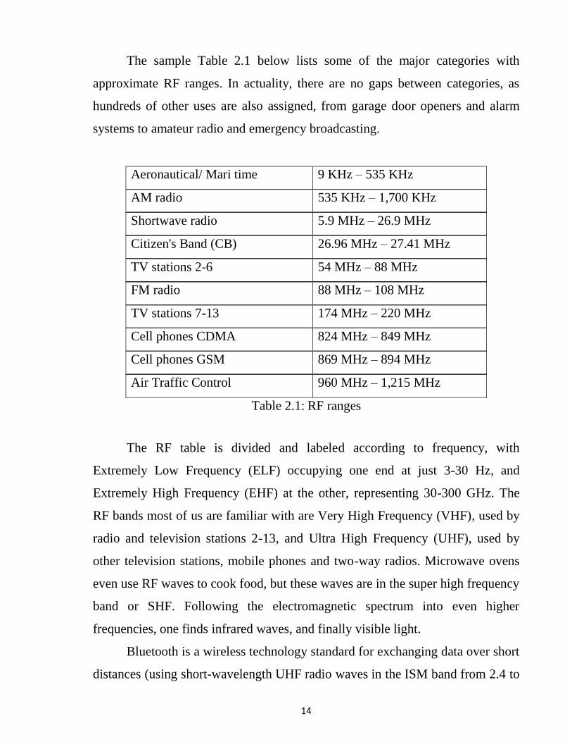
The sample Table 2.1 below lists some of the major categories with
approximate RF ranges. In actuality, there are no gaps between categories, as
hundreds of other uses are also assigned, from garage door openers and alarm
systems to amateur radio and emergency broadcasting.
Aeronautical/ Mari time 9 KHz – 535 KHz
AM radio 535 KHz – 1,700 KHz
Shortwave radio 5.9 MHz – 26.9 MHz
Citizen's Band (CB) 26.96 MHz – 27.41 MHz
TV stations 2-6 54 MHz – 88 MHz
FM radio 88 MHz – 108 MHz
TV stations 7-13 174 MHz – 220 MHz
Cell phones CDMA 824 MHz – 849 MHz
Cell phones GSM 869 MHz – 894 MHz
Air Traffic Control 960 MHz – 1,215 MHz
Table 2.1: RF ranges
The RF table is divided and labeled according to frequency, with
Extremely Low Frequency (ELF) occupying one end at just 3-30 Hz, and
Extremely High Frequency (EHF) at the other, representing 30-300 GHz. The
RF bands most of us are familiar with are Very High Frequency (VHF), used by
radio and television stations 2-13, and Ultra High Frequency (UHF), used by
other television stations, mobile phones and two-way radios. Microwave ovens
even use RF waves to cook food, but these waves are in the super high frequency
band or SHF. Following the electromagnetic spectrum into even higher
frequencies, one finds infrared waves, and finally visible light.
Bluetooth is a wireless technology standard for exchanging data over short
distances (using short-wavelength UHF radio waves in the ISM band from 2.4 to
15
2.485 GHz) from fixed and mobile devices, and building personal area
networks (PANs). Invented by telecom vendor Ericsson in 1994 [5], it was
originally conceived as a wireless alternative to RS-232 data cables. It can
connect several devices, overcoming problems of synchronization. Bluetooth
operates at frequencies between 2402 and 2480 MHz, or 2400 and 2483.5 MHz
including guard bands 2 MHz wide at the bottom end and 3.5 MHz wide at the
top.[3]This is in the globally unlicensed (but not unregulated) Industrial,
Scientific and Medical (ISM) 2.4 GHz short-range radio frequency band.
Bluetooth uses a radio technology called frequency-hopping spread spectrum.
Bluetooth divides transmitted data into packets, and transmits each packet on one
of 79 designated Bluetooth channels. Each channel has a bandwidth of 1MHz. It
usually performs 800 hops per second, with Adaptive Frequency-
Hopping (AFH) enabled.[3] Bluetooth low energy uses 2 MHz spacing, which
accommodates 40 channels.

16
CHAPTER THREE
SYSTEM HARDWARE AND DESIGN 3.1 Introduction
The Robot using RF technology for remote operation attached with
Smartphone having IP webcam application for monitoring purpose. The robot
along with Smartphone can wirelessly transmit real time video and will give
confidential information regarding opposite parties. An Arduino is used as a
controller, attached with Bluetooth module to receive the command signal to
control the movement of the Robot, the command signal is sent by using another
Smartphone. The robot actuators are four DC motors interfaced with the Arduino
by using L293D Shield, which can provide speed and direction control of
motors. The Smartphone with IP web cam application is mounted on the robot
body for spying purpose even in complete darkness by using infrared lighting.
This will send the videos wirelessly to laptop.
3.2 Components As shown from figure 3.1 the system consists of the following components:
Figure 3.1: Complete system diagram

17
3.2.1 Arduino microcontroller Arduino is a small microcontroller board with a USB plug to connect to
your computer and a number of connection sockets that can be wired up to
external electronics, such as motors, relays, light sensors, laser diodes,
loudspeakers, microphones, etc. Arduino can either be powered through the USB
connection from the computer or from a 9V battery. Arduino can be controlled
from the computer or programmed by the computer and then disconnected and
allowed to work independently Arduino microcontroller board is shown in
Figure 3.2
Figure 3.2 The Arduino board
It is an open-source electronics prototyping platform based on flexible,
easy-to-use hardware and software. It’s intended for artists, designers, hobbyists,
and anyone interested in creating inter-active objects or environments in simple
terms, the Arduino is a tiny computer system that can be programmed with your

18
instructions to interact with various forms of input and output. The current
Arduino board model, the Uno is quite small in size.
Although it might not look like much to the new observer, the Arduino
system allows creating devices that can interact with the world. By using an
almost unlimited range of input and output devices, sensors, indicators, displays,
motors, and more, the exact interactions required to create a functional device
can be programmed. For example, artists have created installations with patterns
of blinking lights that respond to the movements of passers-by, high school
students have built autonomous robots that can detect an open flame and
extinguish it, and geographers have designed systems that monitor temperature
and humidity and transmit this data back to their offices via text message. In fact,
there are infinite numbers of examples with a quick search on the Internet.
By taking a quick tour of the Uno Starting at the left side of the board
there are two connectors, as shown in Figure 3.3
Figure 3.3: The USB and power connectors
On the far left is the Universal Serial Bus (USB) connector. This connects
the board to your computer for three reasons; to supply power to the board, to
upload the instructions to the Arduino, and to send data to and receive it from a

19
computer. On the right is the power connector, this connector can power the
Arduino with a standard mains power adapter.
At the lower middle is the heart of the board: the microcontroller, as Show
in Figure 3.4.
.
Figure 3.4: The microcontroller
The microcontrollers represent the “brains” of the Arduino. It is a tiny
computer that contains a processor to execute instructions, includes various types
of memory to hold data and instructions from our sketches, and provides various
avenues of sending and receiving data. Just below the microcontroller are two
rows of small sockets, as shown in Figure 3.5.
Figure 3.5: The power and analog sockets
The first row offers power connections and the ability to use an external
RESET button. The second row offers six analog inputs that are used to measure
electrical signals that vary in voltage. Furthermore, pins A4 and A5 can also be
used for sending data to and receiving it from other devices. Along the top of the
board are two more rows of sockets, as shown in Figure 3.6.
20
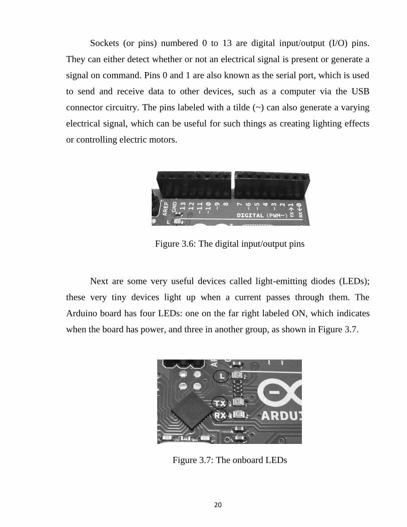
Sockets (or pins) numbered 0 to 13 are digital input/output (I/O) pins.
They can either detect whether or not an electrical signal is present or generate a
signal on command. Pins 0 and 1 are also known as the serial port, which is used
to send and receive data to other devices, such as a computer via the USB
connector circuitry. The pins labeled with a tilde (~) can also generate a varying
electrical signal, which can be useful for such things as creating lighting effects
or controlling electric motors.
Figure 3.6: The digital input/output pins
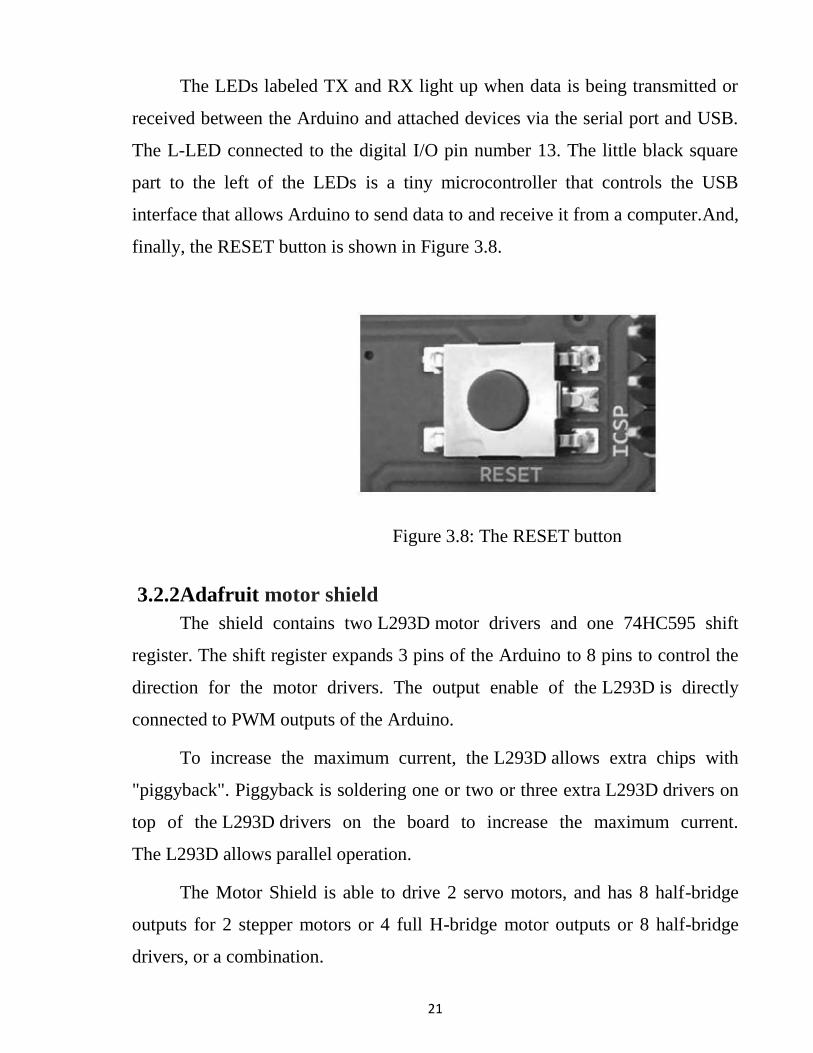
Next are some very useful devices called light-emitting diodes (LEDs);
these very tiny devices light up when a current passes through them. The
Arduino board has four LEDs: one on the far right labeled ON, which indicates
when the board has power, and three in another group, as shown in Figure 3.7.
Figure 3.7: The onboard LEDs
21
The LEDs labeled TX and RX light up when data is being transmitted or
received between the Arduino and attached devices via the serial port and USB.
The L-LED connected to the digital I/O pin number 13. The little black square
part to the left of the LEDs is a tiny microcontroller that controls the USB
interface that allows Arduino to send data to and receive it from a computer.And,
finally, the RESET button is shown in Figure 3.8.
Figure 3.8: The RESET button
3.2.2Adafruit motor shield
The shield contains two L293D motor drivers and one 74HC595 shift
register. The shift register expands 3 pins of the Arduino to 8 pins to control the
direction for the motor drivers. The output enable of the L293D is directly
connected to PWM outputs of the Arduino.
To increase the maximum current, the L293D allows extra chips with
"piggyback". Piggyback is soldering one or two or three extra L293D drivers on
top of the L293D drivers on the board to increase the maximum current.
The L293D allows parallel operation.
The Motor Shield is able to drive 2 servo motors, and has 8 half-bridge
outputs for 2 stepper motors or 4 full H-bridge motor outputs or 8 half-bridge
drivers, or a combination.
22
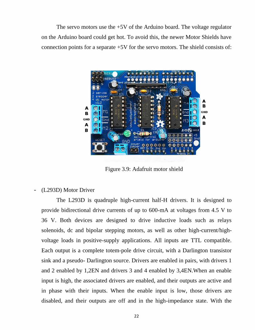
The servo motors use the +5V of the Arduino board. The voltage regulator
on the Arduino board could get hot. To avoid this, the newer Motor Shields have
connection points for a separate +5V for the servo motors. The shield consists of:
Figure 3.9: Adafruit motor shield
- (L293D) Motor Driver
The L293D is quadruple high-current half-H drivers. It is designed to
provide bidirectional drive currents of up to 600-mA at voltages from 4.5 V to
36 V. Both devices are designed to drive inductive loads such as relays
solenoids, dc and bipolar stepping motors, as well as other high-current/high-
voltage loads in positive-supply applications. All inputs are TTL compatible.
Each output is a complete totem-pole drive circuit, with a Darlington transistor
sink and a pseudo- Darlington source. Drivers are enabled in pairs, with drivers 1
and 2 enabled by 1,2EN and drivers 3 and 4 enabled by 3,4EN.When an enable
input is high, the associated drivers are enabled, and their outputs are active and
in phase with their inputs. When the enable input is low, those drivers are
disabled, and their outputs are off and in the high-impedance state. With the
23
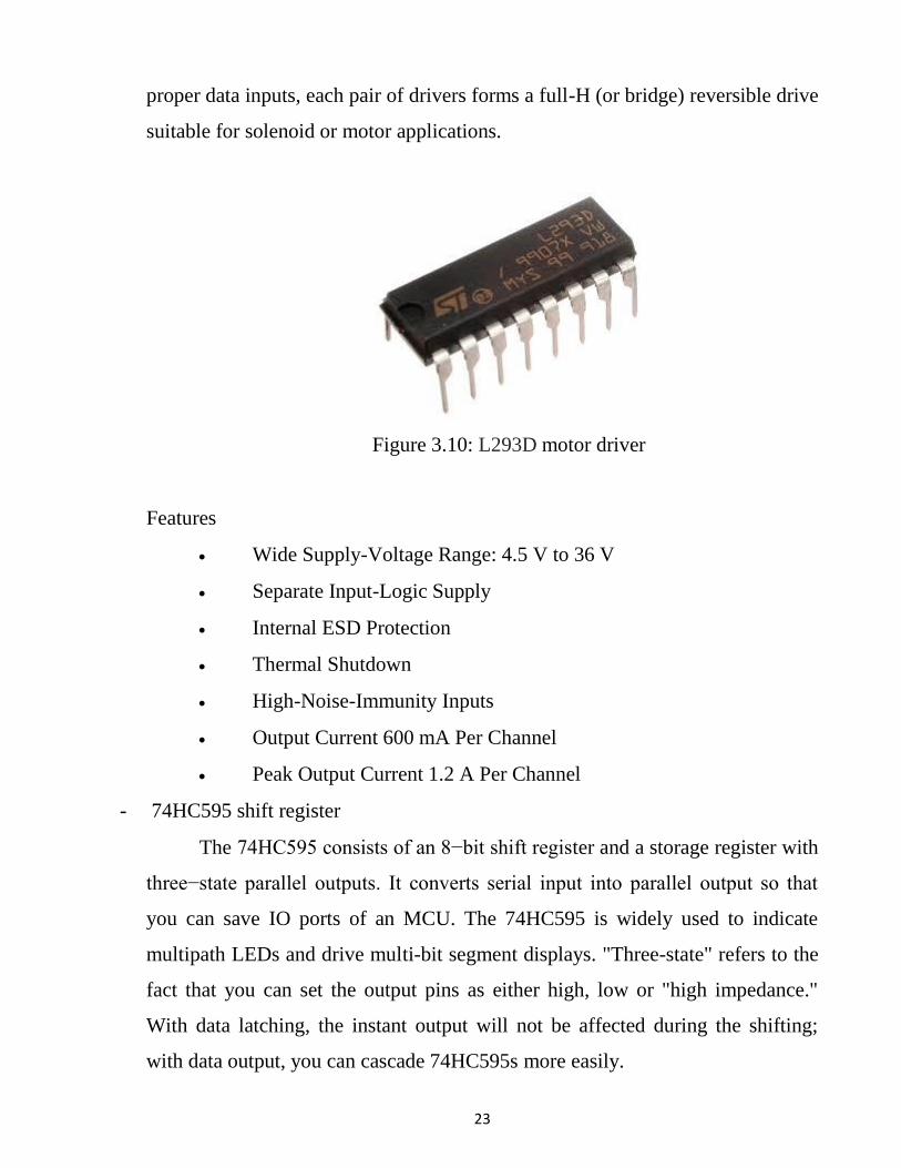
proper data inputs, each pair of drivers forms a full-H (or bridge) reversible drive
suitable for solenoid or motor applications.
Figure 3.10: L293D motor driver
Features
Wide Supply-Voltage Range: 4.5 V to 36 V
Separate Input-Logic Supply
Internal ESD Protection
Thermal Shutdown
High-Noise-Immunity Inputs
Output Current 600 mA Per Channel
Peak Output Current 1.2 A Per Channel
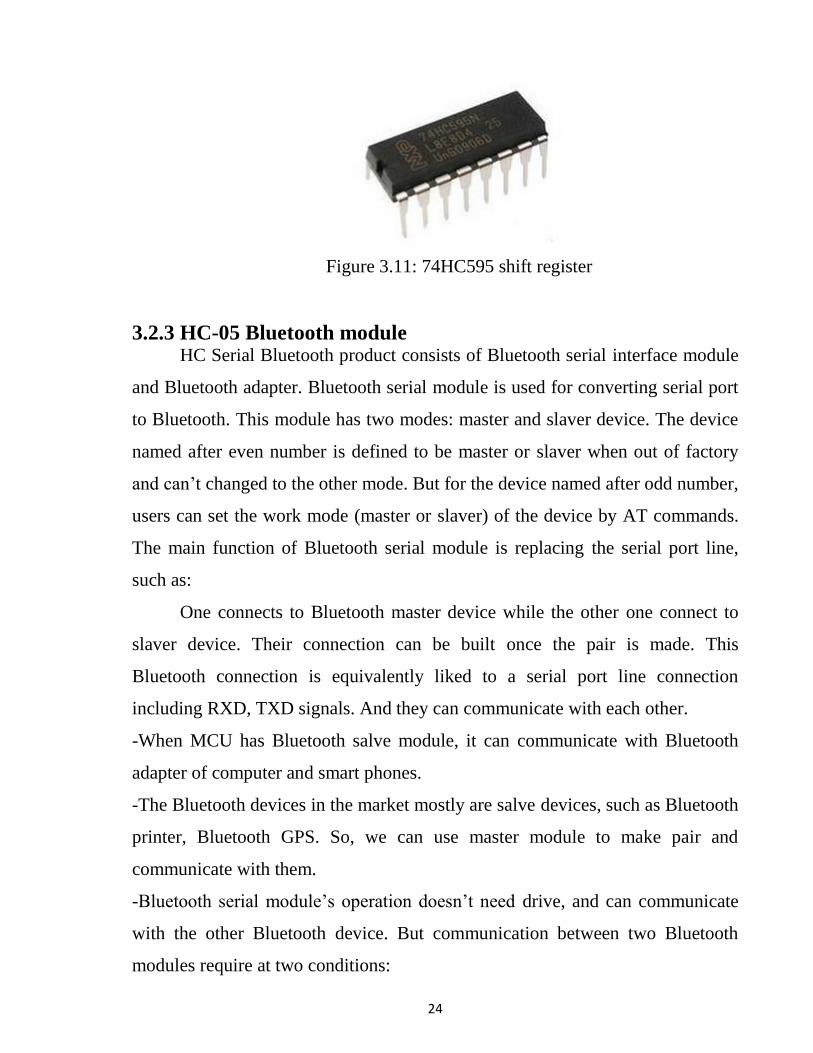
- 74HC595 shift register
The 74HC595 consists of an 8−bit shift register and a storage register with
three−state parallel outputs. It converts serial input into parallel output so that
you can save IO ports of an MCU. The 74HC595 is widely used to indicate
multipath LEDs and drive multi-bit segment displays. "Three-state" refers to the
fact that you can set the output pins as either high, low or "high impedance."
With data latching, the instant output will not be affected during the shifting;
with data output, you can cascade 74HC595s more easily.
24
Figure 3.11: 74HC595 shift register
3.2.3 HC-05 Bluetooth module HC Serial Bluetooth product consists of Bluetooth serial interface module
and Bluetooth adapter. Bluetooth serial module is used for converting serial port
to Bluetooth. This module has two modes: master and slaver device. The device
named after even number is defined to be master or slaver when out of factory
and can’t changed to the other mode. But for the device named after odd number,
users can set the work mode (master or slaver) of the device by AT commands.
The main function of Bluetooth serial module is replacing the serial port line,
such as:
One connects to Bluetooth master device while the other one connect to
slaver device. Their connection can be built once the pair is made. This
Bluetooth connection is equivalently liked to a serial port line connection
including RXD, TXD signals. And they can communicate with each other.
-When MCU has Bluetooth salve module, it can communicate with Bluetooth
adapter of computer and smart phones.
-The Bluetooth devices in the market mostly are salve devices, such as Bluetooth
printer, Bluetooth GPS. So, we can use master module to make pair and
communicate with them.
-Bluetooth serial module’s operation doesn’t need drive, and can communicate
with the other Bluetooth device. But communication between two Bluetooth
modules require at two conditions:

25
-The communication must be between master and slave.
-The password must be correct.
HC-05 embedded Bluetooth serial communication module (can be short
for module) have two work modes: order-response work mode and automatic
connection work mode. And there are three work roles (Master, Slave and
Loopback) at the automatic connection work mode. When the module is at the
automatic connection work mode, it will follow the default way set lastly to
transmit the data automatically. When the module is at the order-response work
mode, user can send the AT command to the module to set the control
parameters and sent control order. The work mode of module can be switched by
controlling the module PIN (PIO11) input level.
Figure 3.12: Bluetooth module
3.2.4 Power supply Two DC batteries, 9-Volt were used; one as power supply to Arduino
controller, and second as power supply to motors through Shield driver.
3.2.5 Smartphone Two Smartphones have been used in the project, one is used for controlling the
spy robot, and the second phone is mounted on the robot which acts as a camera
and sending real time video. Both phones are operated on an Android platform.
26
Android Platform
Android devices are powerful mobile computers and they become more
and more. Popular smart phones used worldwide. They becomes more and more
popular for Software developers because of its powerful capabilities and open
architecture, also it’s based on the java programming language. Because Android
uses the Java Programming language getting started with the Android API is
easy; the API is open and allows easy access to the hardware components.
Android devices provide numerous communication interfaces like USB, Wi-Fi
and Bluetooth, that can be used to connect to the robot. We think it is a great
platform for a robotic system control, because it’s much cheaper than any other
ARM-based processing unit. We use android platform because it is the widest
used in the word and runs the largest number of smart phones worldwide.
3.2.6 Bluetooth RC application
- First make sure your HC-05 Bluetooth module is paired with your mobile. The
default password for pairing is “1234” or “0000”. Check the manual of Bluetooth
module.
- Click on “SELECT DEVICE” icon to select paired Bluetooth module.
- When presses “up arrow” it sends the data “A” to Bluetooth module connected
with the circuit. When microcontroller detects “A” the robot/robot car moves
FORWORD.
- When press “DOWN ARROW” it sends the data “B” to Bluetooth module
connected with the circuit. When microcontroller detects “B” the robot/robot car
moves REVERSE.
- When press “LEFT ARROW” it sends the data “C” to Bluetooth module
connected with the circuit. When microcontroller defects “C” the robot/robot car
turns LEFT.

27
- When press “RIGHT ARROW” it sends the data “D” to Bluetooth module
connected with the circuit. When microcontroller defects “D” the robot/robot car
turns RIGHT.
- When press “STOP” button which is in the centre of remote it sends the data
“E” to the Bluetooth module connected with the circuit. When microcontroller
defects “E” the robot/robot car gets stopped
- Click on “DISCONNECT” icon to disconnect paired Bluetooth module.
Figure 3.13: Bluetooth Software Screen Shot
3.2.7 Ip webcam application
The second phone is amounted on the robot which sending real time video
to receiver via IP Web cam application installed on it. Video Streaming was
accomplished by making use of Wi-Fi Direct. Wi-Fi Direct was used to maintain
the goal of the robot being mobile and able to be used in any location/situation. It
allows connections between two mobile devices or single mobile and Laptop
device without the availability of a router. When compared to Bluetooth, Wi-Fi
Direct surpasses it in both speed and range with speeds of up to 250Mbps, which
was a perfect fit for video streaming purposes. Instead of having a router as an
access point to communicate between two devices, Wi-Fi Direct allows a device

28
to take the role of the access point, also known as the Group Owner. IP Web
Cam software was chosen due to its simplicity. It’s an alternate video encoding
method, has a downside of suffering in quality during fast movement due to how
it’s encoded. Since IP Web Cam is, essentially, independent JPEG images sent at
a fast rate, it can handle fast movement and is the reason for choosing it. To
transmit the IP Web Cam encoded video over a network the HTTP protocol over
TCP was used. TCP allowed for less dropped frames and our high bandwidth
from using Wi-Fi Direct offsets TCP’s drawback of requiring resending every
dropped packet.
29
CHAPTER FOUR
SIMULATION AND SYSTEM
IMPLEMENTATION 4.1 Simulation
The simulation is done by using Protues schematic professional software,
Proteus Simulation is the world's first schematic based micro-controller
simulation tool and quickly became a de-facto standard for teaching embedded
systems within education. Today, it supports more processor families along with
more embedded peripherals and more technologies than any other tool on the
market and we remain world leaders in the field, it allows the engineer to test the
design before it is built for real.
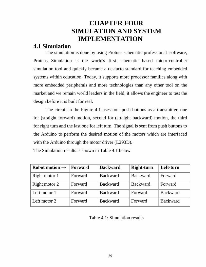
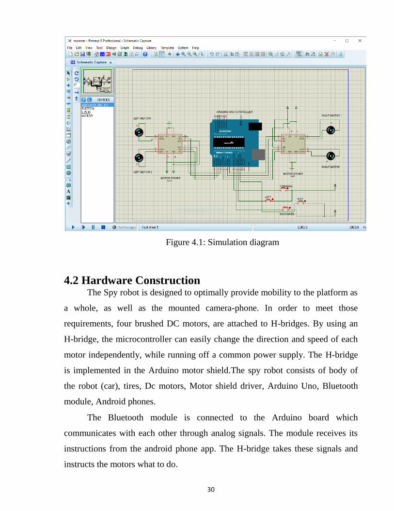
The circuit in the Figure 4.1 uses four push buttons as a transmitter, one
for (straight forward) motion, second for (straight backward) motion, the third
for right turn and the last one for left turn. The signal is sent from push buttons to
the Arduino to perform the desired motion of the motors which are interfaced
with the Arduino through the motor driver (L293D).
The Simulation results is shown in Table 4.1 below
Robot motion → Forward Backward Right-turn Left-turn
Right motor 1 Forward Backward Backward Forward
Right motor 2 Forward Backward Backward Forward
Left motor 1 Forward Backward Forward Backward
Left motor 2 Forward Backward Forward Backward
Table 4.1: Simulation results
30
Figure 4.1: Simulation diagram
4.2 Hardware Construction The Spy robot is designed to optimally provide mobility to the platform as
a whole, as well as the mounted camera-phone. In order to meet those
requirements, four brushed DC motors, are attached to H-bridges. By using an
H-bridge, the microcontroller can easily change the direction and speed of each
motor independently, while running off a common power supply. The H-bridge
is implemented in the Arduino motor shield.The spy robot consists of body of
the robot (car), tires, Dc motors, Motor shield driver, Arduino Uno, Bluetooth
module, Android phones.
The Bluetooth module is connected to the Arduino board which
communicates with each other through analog signals. The module receives its
instructions from the android phone app. The H-bridge takes these signals and
instructs the motors what to do.
31
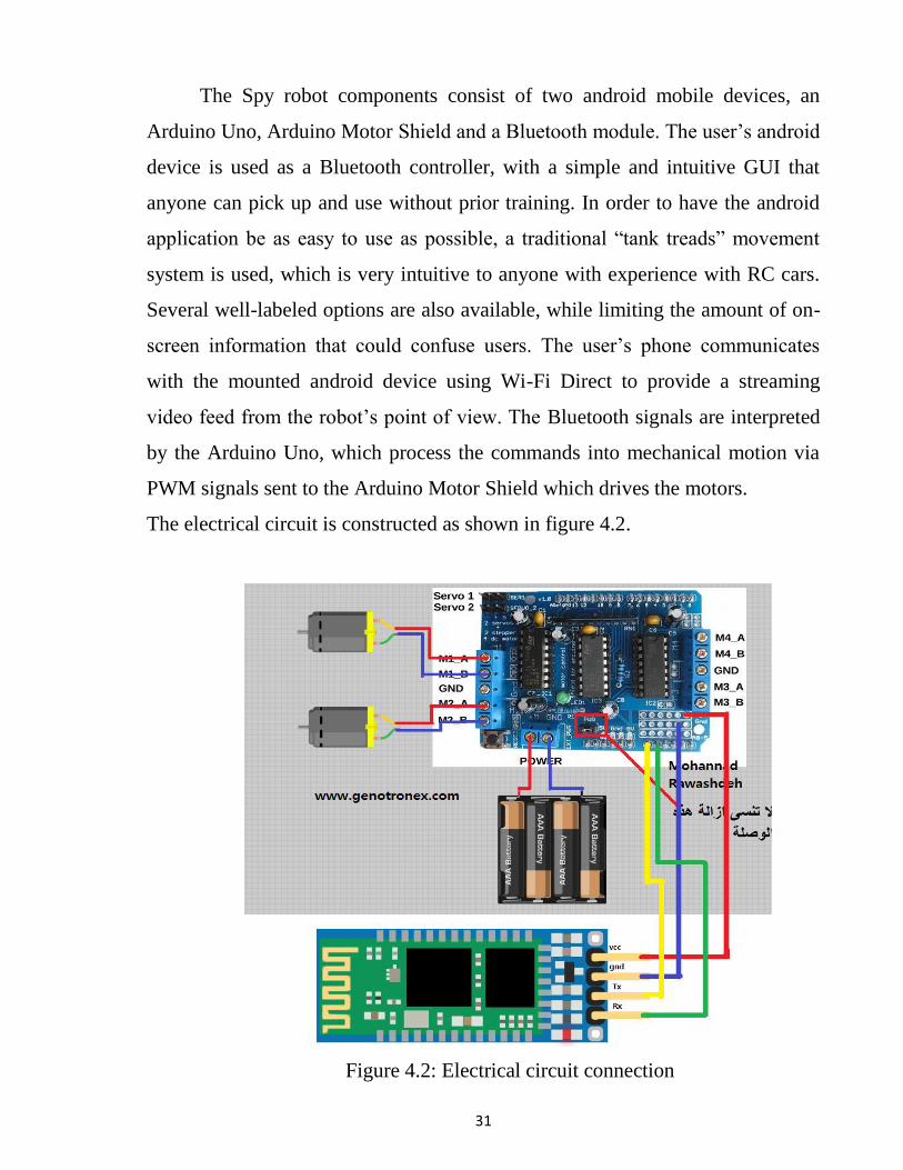
The Spy robot components consist of two android mobile devices, an
Arduino Uno, Arduino Motor Shield and a Bluetooth module. The user’s android
device is used as a Bluetooth controller, with a simple and intuitive GUI that
anyone can pick up and use without prior training. In order to have the android
application be as easy to use as possible, a traditional “tank treads” movement
system is used, which is very intuitive to anyone with experience with RC cars.
Several well-labeled options are also available, while limiting the amount of on-
screen information that could confuse users. The user’s phone communicates
with the mounted android device using Wi-Fi Direct to provide a streaming
video feed from the robot’s point of view. The Bluetooth signals are interpreted
by the Arduino Uno, which process the commands into mechanical motion via
PWM signals sent to the Arduino Motor Shield which drives the motors.
The electrical circuit is constructed as shown in figure 4.2.
Figure 4.2: Electrical circuit connection

32
The overall system is shown in Figure 4.3 below
Figure 4.3 Overall system construction.
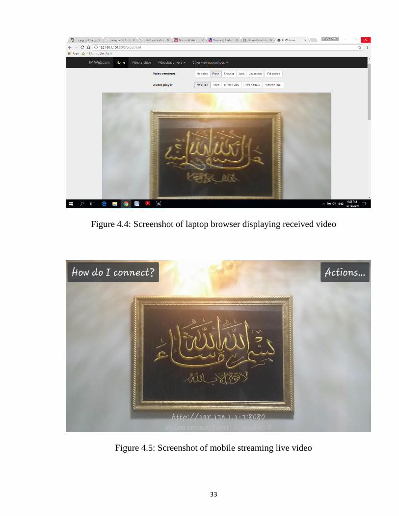
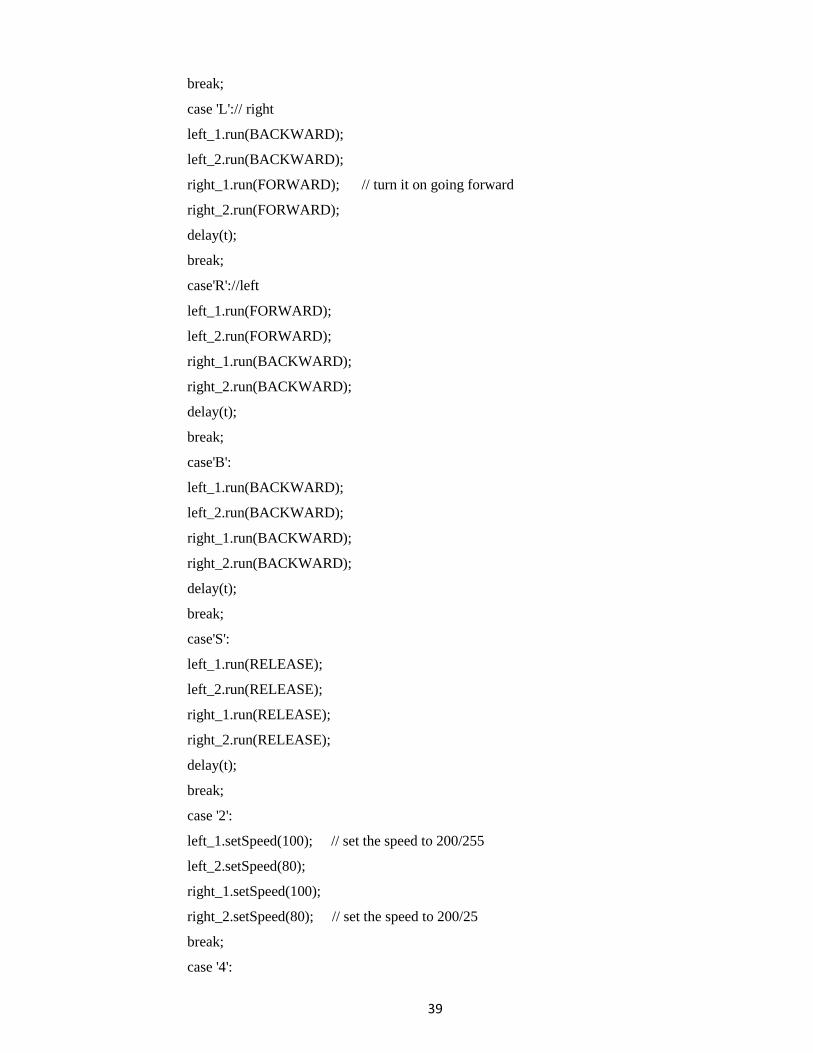
Figure 4.4 Shows the video which sent from robot and displayed on laptop
browser. And Figure 4.5 shows a screenshot of the mobile which used as camera
to broadcast real time video.
33
Figure 4.4: Screenshot of laptop browser displaying received video
Figure 4.5: Screenshot of mobile streaming live video

34
CHAPTER FIVE
CONCLUSION AND RECOMMENDATION 5.1 Conclusion
The implementation of RF based spy robot is done successfully. The
communication is properly done without any interference between different
modules in the design. Design is done to meet all the specifications and
requirements. Software tools like Arduino IDE compiler is used to upload the
source code into the Arduino, Protues schematic professional have been used to
develop the software code before realizing the hardware.
Circuit is implemented in Protues and implemented on the Arduino board.
The performance has been verified both in software simulator and hardware
design. The total circuit is completely verified functionally and is following the
application software. It can be concluded that the design implemented in the
present work provide portability, flexibility and the data transmission is also
done with low power consumption.
5.2 Recommendation 1-The robot can be autonomous by adding an inferred or ultrasonic sensor.
2-The range of control can be expanded by using Wi-Fi module instead of
Bluetooth module.

35
References
[1] Dr. Bob Williams,''An introduction to Robotics'', Ohio University
USA, 2014.
[2] D. Ibrahim, "Advanced PIC Microcontroller Projects in C," 2008
[3] https://inst.eecs.berkeley.edu/~ee128/fa05/labs/lab_7/lab7-intro.pdf
,July 15.
[4] Dogan Ibrahim ,“ Microcontroller Based Applied Digital control ”,
Department of
computer Engineering, Near East University, John Wiley& Sons Ltd, 2006.
[5] Fernando E.Valdes – Perez , Ramon pallas –Areny,“ Microcontrollers:
Fundamentals and Application with PIC ” ,2009.

36
APPENDIX A Simulation Code
void setup() {
pinMode(0,OUTPUT);
pinMode(1,OUTPUT);
pinMode(2,OUTPUT);
pinMode(3,OUTPUT);
pinMode(4,OUTPUT);
pinMode(5,OUTPUT);
pinMode(6,OUTPUT);
pinMode(7,OUTPUT);
pinMode(8,INPUT);
pinMode(9,INPUT);
pinMode(10,INPUT);
pinMode(11,INPUT);
}
void loop() {
if(digitalRead(8)==HIGH)
{digitalWrite(1,HIGH);
digitalWrite(3,HIGH);
digitalWrite(4,HIGH);
digitalWrite(7,HIGH);}
else if (digitalRead(9)==HIGH)
{digitalWrite(0,HIGH);
digitalWrite(2,HIGH);
digitalWrite(5,HIGH);
digitalWrite(6,HIGH);}
else if (digitalRead(10)==HIGH)
{digitalWrite(1,HIGH);
digitalWrite(3,HIGH);
digitalWrite(5,HIGH);
digitalWrite(6,HIGH);
}
else if (digitalRead(11)==HIGH)
{digitalWrite(0,HIGH);

37
digitalWrite(2,HIGH);
digitalWrite(4,HIGH);
digitalWrite(7,HIGH);
}
}

38
APPENDIX B
Hardware code
#include <AFMotor.h>
#include <SoftwareSerial.h>// import the serial library
SoftwareSerial Genotronex(14, 15); // RX, TX
char BluetoothData; // the data given from Computer
int t=10;
AF_DCMotor left_1(1, MOTOR12_1KHZ); // create motor #1, 1KHz pwm
AF_DCMotor left_2(2, MOTOR12_1KHZ); // #2
AF_DCMotor right_1 (3, MOTOR34_1KHZ); // create motor #3, 1KHz pwm
AF_DCMotor right_2 (4, MOTOR34_1KHZ); // #4
void setup() {
// put your setup code here, to run once:
Genotronex.begin(9600);
left_1.setSpeed(200); // set the speed to 200/255
left_2.setSpeed(180); // set the speed to 200/25
right_1.setSpeed(200);
right_1.setSpeed(180);
}
void loop() {
// put your main code here, to run repeatedly:
if (Genotronex.available()){
BluetoothData=Genotronex.read();
delay(t);
switch(BluetoothData){
case 'F':
left_1.run(FORWARD);
left_2.run(FORWARD);
right_1.run(FORWARD);
right_2.run(FORWARD);
delay(t);
39
break;
case 'L':// right
left_1.run(BACKWARD);
left_2.run(BACKWARD);
right_1.run(FORWARD); // turn it on going forward
right_2.run(FORWARD);
delay(t);
break;
case'R'://left
left_1.run(FORWARD);
left_2.run(FORWARD);
right_1.run(BACKWARD);
right_2.run(BACKWARD);
delay(t);
break;
case'B':
left_1.run(BACKWARD);
left_2.run(BACKWARD);
right_1.run(BACKWARD);
right_2.run(BACKWARD);
delay(t);
break;
case'S':
left_1.run(RELEASE);
left_2.run(RELEASE);
right_1.run(RELEASE);
right_2.run(RELEASE);
delay(t);
break;
case '2':
left_1.setSpeed(100); // set the speed to 200/255
left_2.setSpeed(80);
right_1.setSpeed(100);
right_2.setSpeed(80); // set the speed to 200/25
break;
case '4':

40
left_1.setSpeed(150); // set the speed to 200/255
left_2.setSpeed(130);
right_1.setSpeed(150);
right_2.setSpeed(130); // set the speed to 200/25
break;
case'7':
left_1.setSpeed(200);
left_2.setSpeed(180);// set the speed to 200/255
right_1.setSpeed(200); // set the speed to 200/25
right_2.setSpeed(180);
break;
case'q':
left_1.setSpeed(250); // set the speed to 200/255
left_2.setSpeed(230);
right_1.setSpeed(250);
right_2.setSpeed(230); // set the speed to 200/25
}
}
}
Related Documents


