Sudan University of Science and Technology College of Graduate Studies A Thesis Submitted in Partial Fulfillment of the Requirements for the Degree of M.Sc. in Mechanical Engineering (Power) ﺗﻌﺩﻳﻝ ﻧﻅﺎﻡ ﺍﻟﻭﻗﻭﺩ ﻓﻲ ﺗﻭﺭﺑﻳﻧﺎﺕ ﻗﺭﻱ ﺍﻟﻐﺎﺯﻳﺔPrepared by: Marwan Haroon Mohammed Abdallah Supervisor: Dr. Tawfig Ahmed Gamal April 2019

Welcome message from author
This document is posted to help you gain knowledge. Please leave a comment to let me know what you think about it! Share it to your friends and learn new things together.
Transcript
Sudan University of Science and
Technology
College of Graduate Studies
A Thesis Submitted in Partial Fulfillment of the Requirements
for the Degree of M.Sc. in Mechanical Engineering (Power)
الغازية قري توربينات تعديل نظام الوقود في
Prepared by:
Marwan Haroon Mohammed Abdallah
Supervisor:
Dr. Tawfig Ahmed Gamal
April 2019

I
اآليـــــــــة
:قال اهللا تعالي
الرحيمبسم هللا الرحمن
286 اآلية -سورة البقرة

II
DEDICATION
To my moTher
To my faTher
To my beloved, who
consTanT prayer,
sacrifice, and inspiraTion
led To This wonderful
accomplishmenT
III
ACKNOWLEDGMENT
All praises and thanks are due to ALLAH (Subhanaho WA
taala) for bestowing me with health, knowledge, and patience
to complete this work.
Thereafter, acknowledgments are to GARRI combined cycle
power plant.
Thanks to my supervisor:
Dr. Twafig Ahmed Gamal
For his assistance, guidance and endless help throughout the
step of this research work.
My sincere thanks to:
Mr. Moiz Osman Awad
Mr. Yousif Ahmed Abdulkarim
Thanks for anyone help me to make this work.
IV
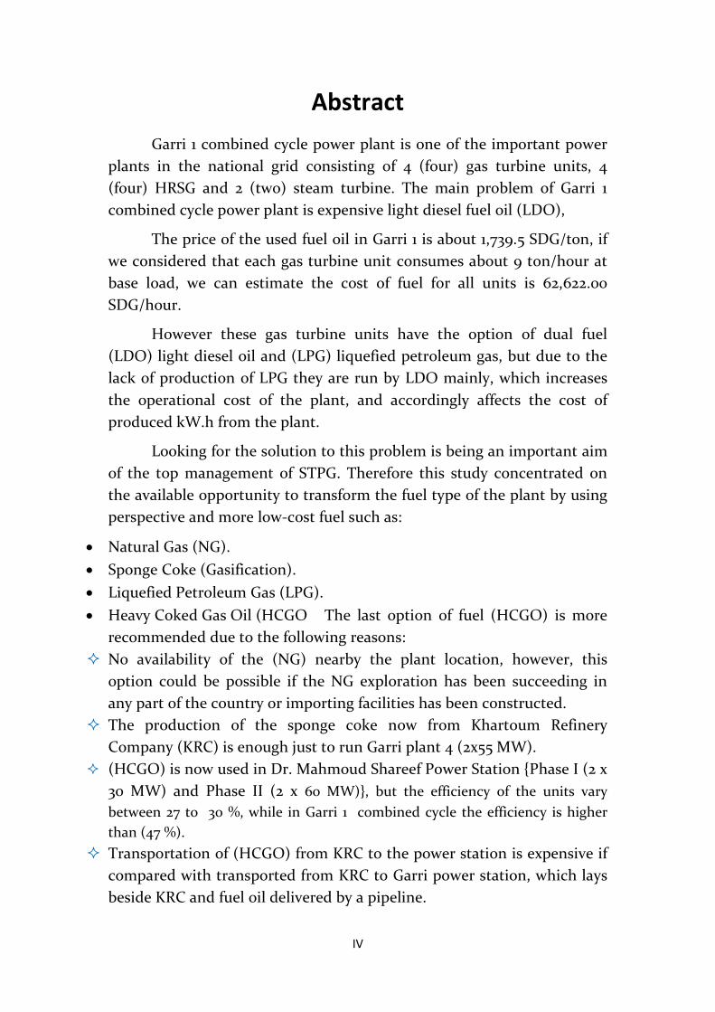
Abstract Garri 1 combined cycle power plant is one of the important power
plants in the national grid consisting of 4 (four) gas turbine units, 4 (four) HRSG and 2 (two) steam turbine. The main problem of Garri 1 combined cycle power plant is expensive light diesel fuel oil (LDO),
The price of the used fuel oil in Garri 1 is about 1,739.5 SDG/ton, if we considered that each gas turbine unit consumes about 9 ton/hour at base load, we can estimate the cost of fuel for all units is 62,622.00 SDG/hour.
However these gas turbine units have the option of dual fuel (LDO) light diesel oil and (LPG) liquefied petroleum gas, but due to the lack of production of LPG they are run by LDO mainly, which increases the operational cost of the plant, and accordingly affects the cost of produced kW.h from the plant.
Looking for the solution to this problem is being an important aim of the top management of STPG. Therefore this study concentrated on the available opportunity to transform the fuel type of the plant by using perspective and more low-cost fuel such as:
• Natural Gas (NG). • Sponge Coke (Gasification). • Liquefied Petroleum Gas (LPG). • Heavy Coked Gas Oil (HCGO The last option of fuel (HCGO) is more
recommended due to the following reasons: No availability of the (NG) nearby the plant location, however, this
option could be possible if the NG exploration has been succeeding in any part of the country or importing facilities has been constructed.
The production of the sponge coke now from Khartoum Refinery Company (KRC) is enough just to run Garri plant 4 (2x55 MW).
(HCGO) is now used in Dr. Mahmoud Shareef Power Station {Phase I (2 x 30 MW) and Phase II (2 x 60 MW)}, but the efficiency of the units vary between 27 to 30 %, while in Garri 1 combined cycle the efficiency is higher than (47 %).
Transportation of (HCGO) from KRC to the power station is expensive if compared with transported from KRC to Garri power station, which lays beside KRC and fuel oil delivered by a pipeline.
V
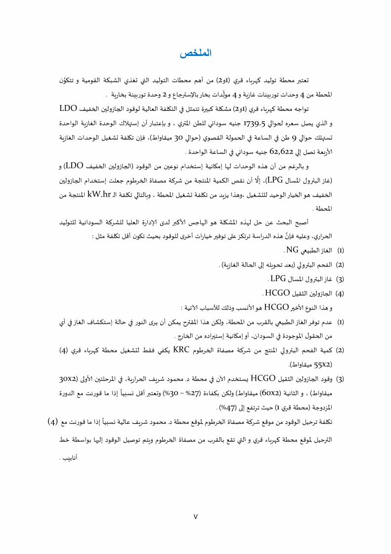
الملخص
ن من أهم ) 2و1(�عت�� محطة توليد كهر�اء قري محطات التوليد ال�ي �غذي الشبكة القومية و تت�و
دات بخار باإلس��جاع و 4وحدات تور�ينات غاز�ة و 4املحطة من .وحدة تور�ينة بخار�ة 2مول
LDOمش�لة كب��ة تتمثل �� الت�لفة العالية لوقود ا�جازول�ن ا�خفيف ) 2و1(تواجه محطة كهر�اء قري
جنيه سودا�ي للطن امل��ي ، و بإعتبار أن إس��الك الوحدة الغاز�ة الواحدة 1739.5و الذي يصل سعره �حوا��
، فإن ت�لفة �شغيل الوحدات الغاز�ة )ميقاواط 30حوا�� (طن �� الساعة �� ا�حمولة القصوي 9�س��لك حوا��
.جنيه سودا�ي �� الساعة الواحدة 62,622�� إار�عة تصل
و ) LDOا�جازول�ن ا�خفيف (و بالرغم من أن هذه الوحدات لها إم�انية إستخدام نوع�ن من الوقود
أن نقص الكمية املنتجة من شركة مصفاة ا�خرطوم جعلت إستخدام ا�جازول�ن )LPGغاز الب��ول املسال (
، إال
املنتجة من kW.hrالتا�� ت�لفة الـ ا�خفيف هو ا�خيار الوحيد للتشغيل ،وهذا يز�د من ت�لفة �شغيل املحطة ، و�
.املحطة
لد ادارة العليا للشركة السودانية للتوليد أبب البح عن حل لهذه املش�لة هو الهاج اك��
:ا�حراري، وعليه فإن هذه الدراسة ترتكز ع�� توف�� خيارات أخر للوقود بحي ت�ون أقل ت�لفة مثل
. NGالغاز الطبي�� )1(
) .�عد تحو�له إ�� ا�حالة الغاز�ة(��و�� الفحم الب )2(
. LPGغاز الب��ول املسال )3(
. HCGOا�جازول�ن الثقيل )4(
:هو ا�س وللك لسسبا اتية HCGOو هذا النوع اخ��
عدم توفر الغاز الطبي�� بالقر من املحطة، ولكن هذا املق��ح يمكن أن ير النور �� حالة إستكشاف الغاز �� أي )1(
.ول املوجودة �� السودان، أو إم�انية إست��اده من ا�خارج من ا�حق
) 4(يكفي فقط لتشغيل محطة كهر�اء قري KRCكمية الفحم الب��و�� املنتج من شركة مصفاة ا�خرطوم )2(
)2x55 ميقاواط.(
2x30(محمود شر�ف ا�حرار�ة، �� املرحلت�ن او�� . سستخدم ان �� محطة د HCGOوقود ا�جازول�ن الثقيل )3(
إلا ما قورنت مع الدورة %) 30~ % 27(ولكن بكفاءة ) ميقاواط) 2x60(، و الثانية ) ميقاواطو�عت�� أقل �سبيا
%) .47(حي ترتفع إ�� ) 1محطة قري (املزدوجة
إلا ما قورنت مع . ت�لفة ترحيل الوقود من موقع شركة مصفاة ا�خرطوم ملوقع محطة د (4)محمود شر�ف عالية �سبيا
ملوقع محطة كهر�اء قري و ال�ي تقع بالقر من مصفاة ا�خرطوم و�تم توبيل الوقود إل��ا بواسطة خط ال��حيل
.أنابي
VI
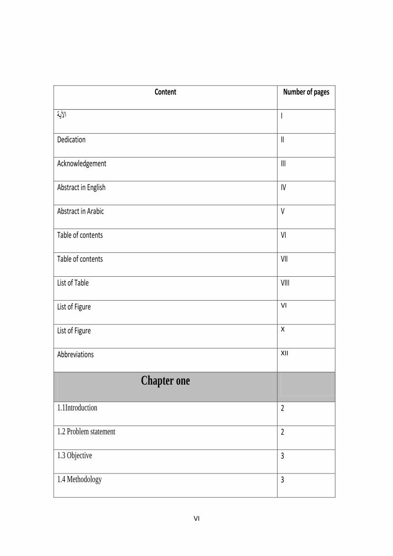
Content Number of pages
I اآلية
Dedication II
Acknowledgement III
Abstract in English IV
Abstract in Arabic V
Table of contents VI
Table of contents VII
List of Table VIII
List of Figure VI
List of Figure X
Abbreviations XII
Chapter one
1.1Introduction 2
1.2 Problem statement 2
1.3 Objective 3
1.4 Methodology 3
VII
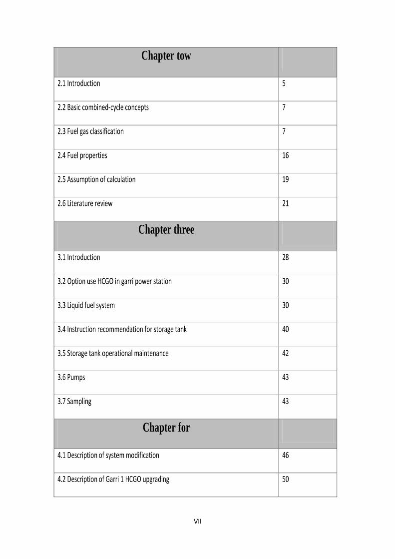
Chapter tow
2.1 Introduction 5
2.2 Basic combined-cycle concepts 7
2.3 Fuel gas classification 7
2.4 Fuel properties 16
2.5 Assumption of calculation 19
2.6 Literature review 21
Chapter three
3.1 Introduction 28
3.2 Option use HCGO in garri power station 30
3.3 Liquid fuel system 30
3.4 Instruction recommendation for storage tank 40
3.5 Storage tank operational maintenance 42
3.6 Pumps 43
3.7 Sampling 43
Chapter for
4.1 Description of system modification 46
4.2 Description of Garri 1 HCGO upgrading 50
VIII
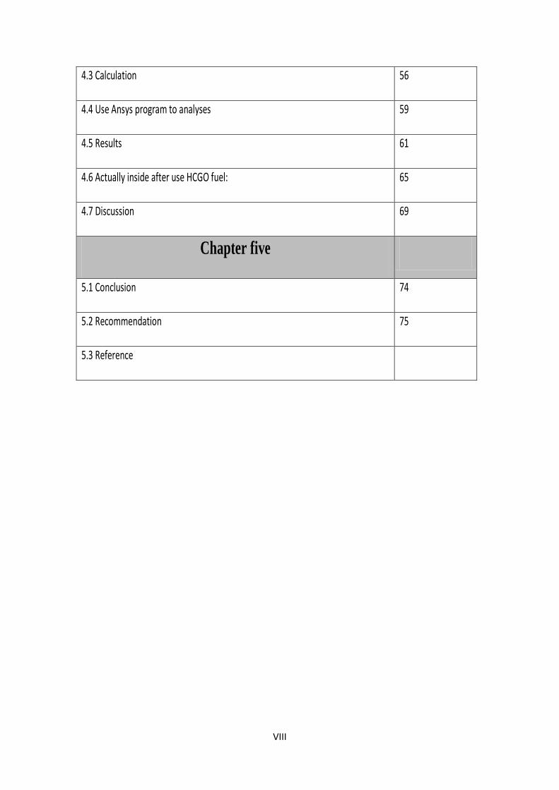
4.3 Calculation 56
4.4 Use Ansys program to analyses 59
4.5 Results 61
4.6 Actually inside after use HCGO fuel: 65
4.7 Discussion 69
Chapter five
5.1 Conclusion 74
5.2 Recommendation 75
5.3 Reference
IX
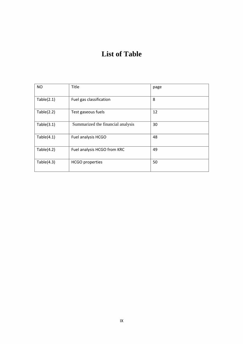
List of Table
NO Title page
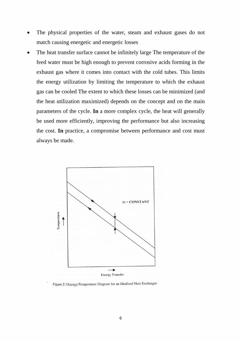
Table(2.1) Fuel gas classification 8
Table(2.2) Test gaseous fuels 12
Table(3.1) Summarized the financial analysis 30
Table(4.1) Fuel analysis HCGO 48
Table(4.2) Fuel analysis HCGO from KRC 49
Table(4.3) HCGO properties 50
X
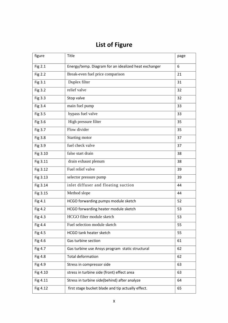
List of Figure figure Title page
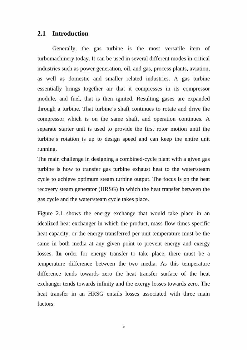
Fig 2.1 Energy/temp. Diagram for an idealized heat exchanger 6
Fig 2.2 Break-even fuel price comparison 21
Fig 3.1 Duplex filter 31
Fig 3.2 relief valve 32
Fig 3.3 Stop valve 32
Fig 3.4 main fuel pump 33
Fig 3.5 bypass fuel valve 33
Fig 3.6 High pressure filter 35
Fig 3.7 Flow divider 35
Fig 3.8 Starting motor 37
Fig 3.9 fuel check valve 37
Fig 3.10 false start drain 38
Fig 3.11 drain exhaust plenum 38
Fig 3.12 Fuel relief valve 39
Fig 3.13 selector pressure pump 39
Fig 3.14 inlet diffuser and floating suction 44
Fig 3.15 Method slope 44
Fig 4.1 HCGO forwarding pumps module sketch 52
Fig 4.2 HCGO forwarding heater module sketch 53
Fig 4.3 HCGO filter module sketch 53
Fig 4.4 Fuel selection module sketch 55
Fig 4.5 HCGO tank heater sketch 55
Fig 4.6 Gas turbine section 61
Fig 4.7 Gas turbine use Ansys program static structural 62
Fig 4.8 Total deformation 62
Fig 4.9 Stress in compressor side 63
Fig 4.10 stress in turbine side (front) effect area 63
Fig 4.11 Stress in turbine side(behind) after analyze 64
Fig 4.12 first stage bucket blade and tip actually effect. 65
XI
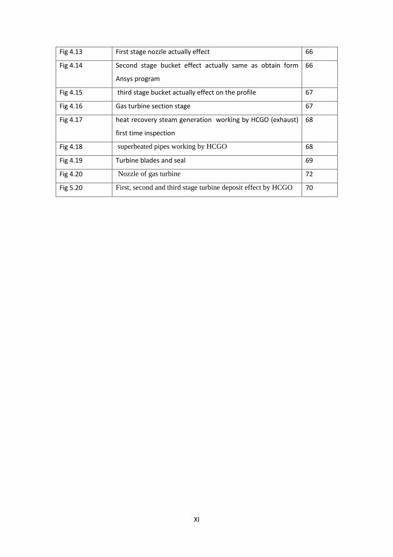
Fig 4.13 First stage nozzle actually effect 66
Fig 4.14 Second stage bucket effect actually same as obtain form
Ansys program
66
Fig 4.15 third stage bucket actually effect on the profile 67
Fig 4.16 Gas turbine section stage 67
Fig 4.17 heat recovery steam generation working by HCGO (exhaust)
first time inspection
68
Fig 4.18 superheated pipes working by HCGO 68
Fig 4.19 Turbine blades and seal 69
Fig 4.20 Nozzle of gas turbine 72
Fig 5.20 First, second and third stage turbine deposit effect by HCGO 70
XII
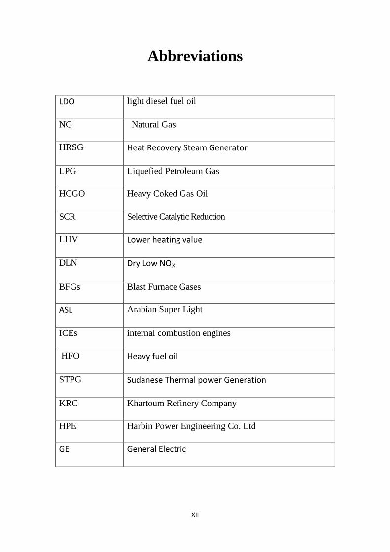
Abbreviations
LDO light diesel fuel oil
NG Natural Gas
HRSG Heat Recovery Steam Generator
LPG Liquefied Petroleum Gas
HCGO Heavy Coked Gas Oil
SCR Selective Catalytic Reduction
LHV Lower heating value
DLN Dry Low NOX
BFGs Blast Furnace Gases
ASL Arabian Super Light
ICEs internal combustion engines
HFO Heavy fuel oil
STPG Sudanese Thermal power Generation
KRC Khartoum Refinery Company
HPE Harbin Power Engineering Co. Ltd
GE General Electric

1
Chapter 1
2
1.1 Introduction
Garri 1 combined cycle power plant is one of the important power plants
in the national grid consisting of (four) gas turbine units, (four) HRSG and
(two) steam turbine. The main problem of Garri 1 combined cycle power plant
is expensive light diesel fuel oil (LDO).
The price of the used fuel oil in Garri 1 is about 1,739.5 SDG/ton, if we
considered that each gas turbine unit consumes about 9 ton/hour at base load,
we can estimate the cost of fuel for all units is 62,622.00 SDG/hour.
However these gas turbine units have the option of dual fuel (LDO) light diesel
oil and (LPG) liquefied petroleum gas, but due to the lack of production of
LPG they are run by LDO mainly, which increases the operational cost of the
plant, and accordingly affects the cost of produced kW.h from the plant.
Looking for the solution to this problem is being an important aim of the top
management of STPG. Therefore this study concentrated on the available
opportunity to transform the fuel type of the plant by using perspective and
more low-cost fuel such as:
Natural Gas (NG).
Sponge Coke (Gasification).
Liquefied Petroleum Gas (LPG).
Heavy Coked Gas Oil (HCGO).
1.2 Problem statement
The problem of this business case appears in the high operational cost due to
the increase in (LDO) fuel prices. The problem takes its importance from the
competition between the power generation types, in which the low cost (kW.hr)
is highly recommended. And also study effectively in turbine side first, second
and third stage bucket.

3
1.3 Objectives
1.3.1 Main objective
The base case of study is to operate the Garri combined cycle power station with LDO
Use (HCGO) in Garri Power Station, visibility and effective in bucket gas turbine
1.3.2 General objectives:
Reduce use of light diesel oil for other machine and cars.
1.4 Methodology
This option is mainly based on using the (HCGO) as fuel in combination with
(LDO) (which will be used only in start-up and shut-down) of gas turbine units
in Garri combined cycle power plant.
This option requires some modifications and additional systems to be installed
such as heating system, fuel treatment system, filtration skid, etc.
.

4
Chapter 2
5
2.1 Introduction
Generally, the gas turbine is the most versatile item of
turbomachinery today. It can be used in several different modes in critical
industries such as power generation, oil, and gas, process plants, aviation,
as well as domestic and smaller related industries. A gas turbine
essentially brings together air that it compresses in its compressor
module, and fuel, that is then ignited. Resulting gases are expanded
through a turbine. That turbine’s shaft continues to rotate and drive the
compressor which is on the same shaft, and operation continues. A
separate starter unit is used to provide the first rotor motion until the
turbine’s rotation is up to design speed and can keep the entire unit
running.
The main challenge in designing a combined-cycle plant with a given gas
turbine is how to transfer gas turbine exhaust heat to the water/steam
cycle to achieve optimum steam turbine output. The focus is on the heat
recovery steam generator (HRSG) in which the heat transfer between the
gas cycle and the water/steam cycle takes place.
Figure 2.1 shows the energy exchange that would take place in an
idealized heat exchanger in which the product, mass flow times specific
heat capacity, or the energy transferred per unit temperature must be the
same in both media at any given point to prevent energy and exergy
losses. In order for energy transfer to take place, there must be a
temperature difference between the two media. As this temperature
difference tends towards zero the heat transfer surface of the heat
exchanger tends towards infinity and the exergy losses towards zero. The
heat transfer in an HRSG entails losses associated with three main
factors:
6
• The physical properties of the water, steam and exhaust gases do not
match causing energetic and energetic losses
• The heat transfer surface cannot be infinitely large The temperature of the
feed water must be high enough to prevent corrosive acids forming in the
exhaust gas where it comes into contact with the cold tubes. This limits
the energy utilization by limiting the temperature to which the exhaust
gas can be cooled The extent to which these losses can be minimized (and
the heat utilization maximized) depends on the concept and on the main
parameters of the cycle. In a more complex cycle, the heat will generally
be used more efficiently, improving the performance but also increasing
the cost. In practice, a compromise between performance and cost must
always be made.
7
2.2 BASIC COMBINED-CYCLE CONCEPTS In this section, the most common combined-cycle concepts are
presented and explained, starting with the most simple and leading to
more complex cycles. A heat balance for each of the main cycle concepts
is given, based on ISO conditions (ambient temperature 15°C, (59°F);
ambient pressure 1.013 bar, (14.7 psi); relative humidity 60%; condenser
vacuum 0.9 bar ; sequential combustion gas turbine, rated at 41.259 MW
and a steam turbine with water cooled condenser. The gas turbine is
equipped with cooling air coolers that generate additional steam for the
water/steam cycle and boost the steam turbine output. Due to the fact that
these features are the same for all of the heat balances, a clear comparison
can be made between them showing how the cycle concept influences the
heat utilization.
2.3 Fuel Gas Classification
General
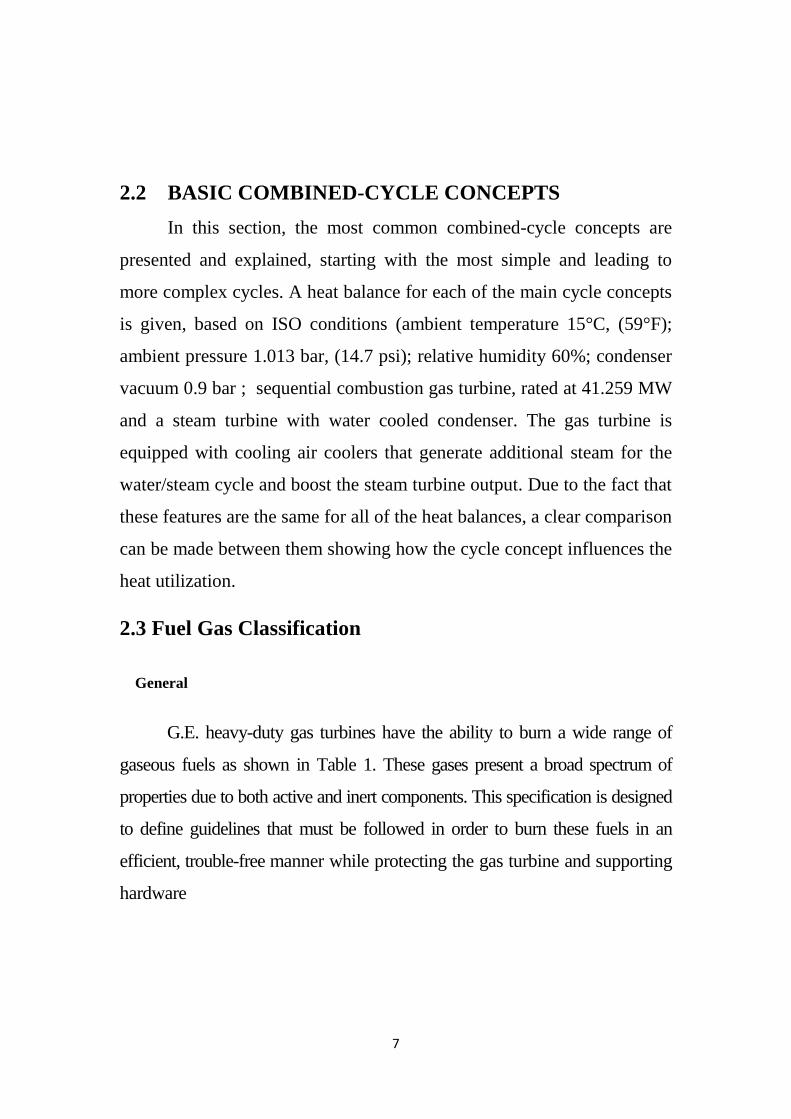
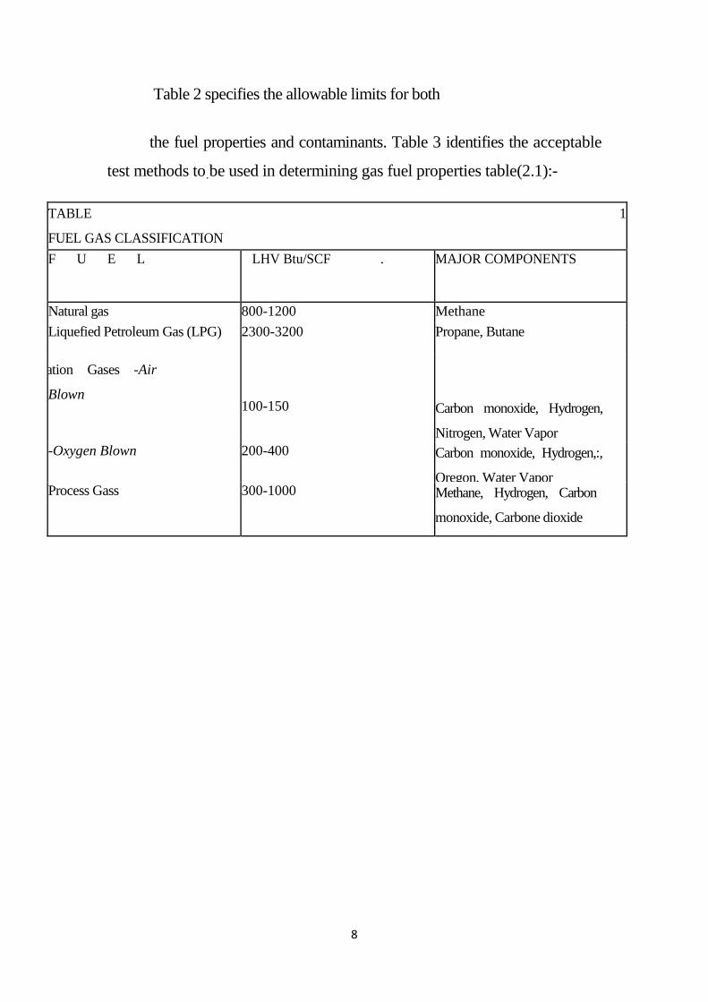
G.E. heavy-duty gas turbines have the ability to burn a wide range of
gaseous fuels as shown in Table 1. These gases present a broad spectrum of
properties due to both active and inert components. This specification is designed
to define guidelines that must be followed in order to burn these fuels in an
efficient, trouble-free manner while protecting the gas turbine and supporting
hardware
8
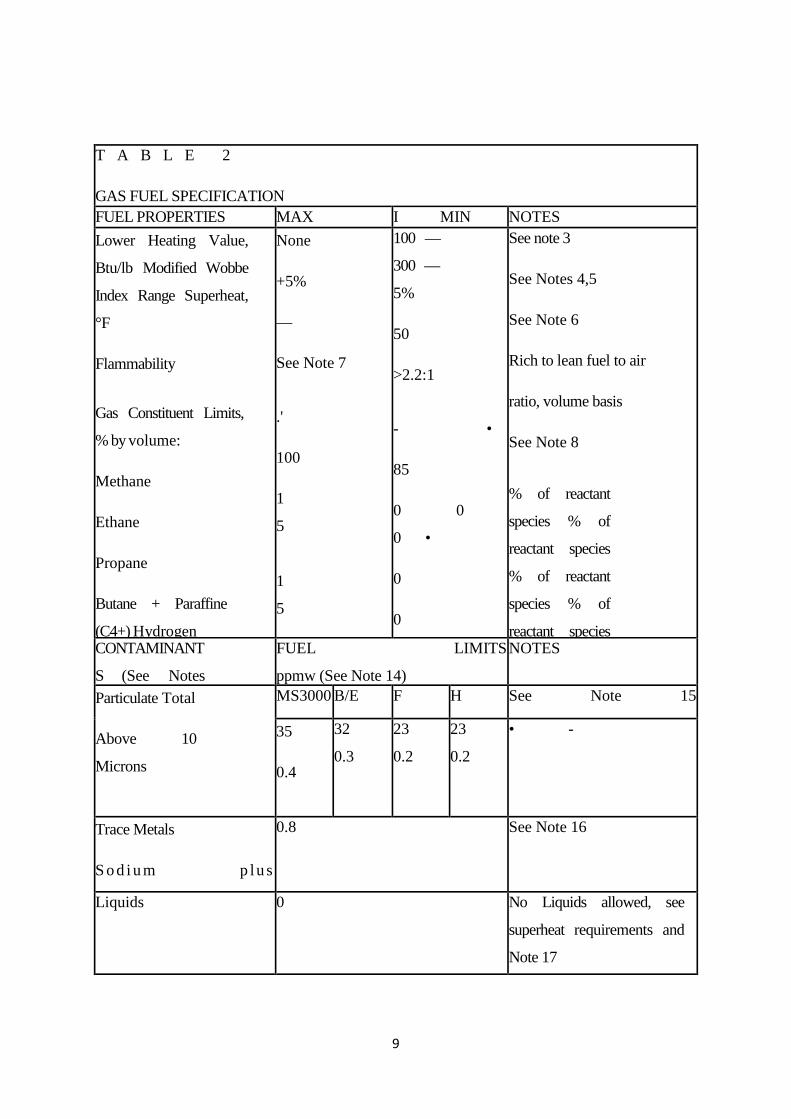
Table 2 specifies the allowable limits for both
the fuel properties and contaminants. Table 3 identifies the acceptable
test methods to.
TABLE 1
FUEL GAS CLASSIFICATION
be used in determining gas fuel properties table(2.1):-
F U E L LHV Btu/SCF . MAJOR COMPONENTS
Natural gas 800-1200 Methane Liquefied Petroleum Gas (LPG) 2300-3200 Propane, Butane
ation Gases -Air
Blown 100-150 Carbon monoxide, Hydrogen,
Nitrogen, Water Vapor -Oxygen Blown 200-400 Carbon monoxide, Hydrogen,:,
Oregon, Water Vapor Process Gass 300-1000 Methane, Hydrogen, Carbon
monoxide, Carbone dioxide
9
T A B L E 2
GAS FUEL SPECIFICATION FUEL PROPERTIES MAX I MIN NOTES Lower Heating Value,
Btu/lb Modified Wobbe
Index Range Superheat,
°F
Flammability
Gas Constituent Limits,
% by volume:
Methane
Ethane
Propane
Butane + Paraffine
(C4+) Hydrogen
None
+5%
—
See Note 7
.'
100
1
5
1
5
100 —
300 —
5%
50
>2.2:1
- •
85
0 0
0 •
0
0
See note 3
See Notes 4,5
See Note 6
Rich to lean fuel to air
ratio, volume basis
See Note 8
% of reactant
species % of
reactant species
% of reactant
species % of
reactant species
CONTAMINANT
S (See Notes
FUEL LIMITS
ppmw (See Note 14)
NOTES
Particulate Total
Above 10
Microns
MS3000
MS5000
B/E
Cl
F
Cl
H
Cl
See Note 15
35
0.4
32
0.3
23
0.2
23
0.2
• -
Trace Metals
S o d i u m p lu s
0.8 See Note 16
Liquids 0 No Liquids allowed, see
superheat requirements and
Note 17
10
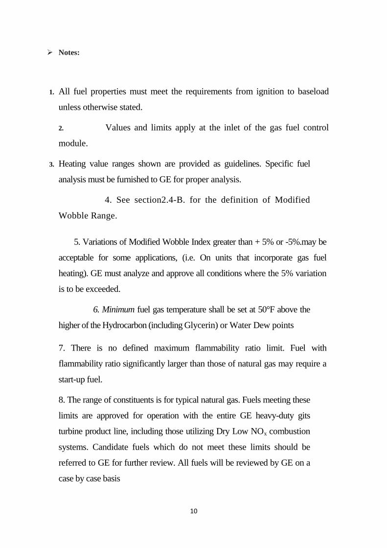
Notes:
1. All fuel properties must meet the requirements from ignition to baseload
unless otherwise stated.
2. Values and limits apply at the inlet of the gas fuel control
module.
3. Heating value ranges shown are provided as guidelines. Specific fuel
analysis must be furnished to GE for proper analysis.
4. See section2.4-B. for the definition of Modified
Wobble Range.
5. Variations of Modified Wobble Index greater than + 5% or -5%.may be
acceptable for some applications, (i.e. On units that incorporate gas fuel
heating). GE must analyze and approve all conditions where the 5% variation
is to be exceeded.
6. Minimum fuel gas temperature shall be set at 50°F above the
higher of the Hydrocarbon (including Glycerin) or Water Dew points
7. There is no defined maximum flammability ratio limit. Fuel with
flammability ratio significantly larger than those of natural gas may require a
start-up fuel.
8. The range of constituents is for typical natural gas. Fuels meeting these
limits are approved for operation with the entire GE heavy-duty gits
turbine product line, including those utilizing Dry Low NOx combustion
systems. Candidate fuels which do not meet these limits should be
referred to GE for further review. All fuels will be reviewed by GE on a
case by case basis
11
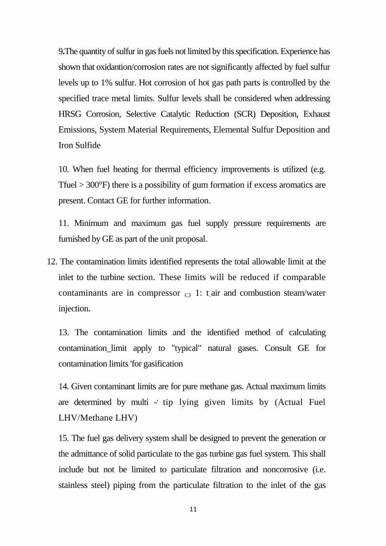
9.The quantity of sulfur in gas fuels not limited by this specification. Experience has
shown that oxidantion/corrosion rates are not significantly affected by fuel sulfur
levels up to 1% sulfur. Hot corrosion of hot gas path parts is controlled by the
specified trace metal limits. Sulfur levels shall be considered when addressing
HRSG Corrosion, Selective Catalytic Reduction (SCR) Deposition, Exhaust
Emissions, System Material Requirements, Elemental Sulfur Deposition and
Iron Sulfide
10. When fuel heating for thermal efficiency improvements is utilized (e.g.
Tfuel > 300°F) there is a possibility of gum formation if excess aromatics are
present. Contact GE for further information.
11. Minimum and maximum gas fuel supply pressure requirements are
furnished by GE as part of the unit proposal.
12. The contamination limits identified represents the total allowable limit at the
inlet to the turbine section. These limits will be reduced if comparable
contaminants are in compressor CJ 1: t.
13. The contamination limits and the identified method of calculating
contamination_limit apply to "typical" natural gases. Consult GE for
contamination limits 'for gasification
air and combustion steam/water
injection.
14. Given contaminant limits are for pure methane gas. Actual maximum limits
are determined by multi -,
15. The fuel gas delivery system shall be designed to prevent the generation or
the admittance of solid particulate to the gas turbine gas fuel system. This shall
include but not be limited to particulate filtration and noncorrosive (i.e.
stainless steel) piping from the particulate filtration to the inlet of the gas
tip lying given limits by (Actual Fuel
LHV/Methane LHV)
12
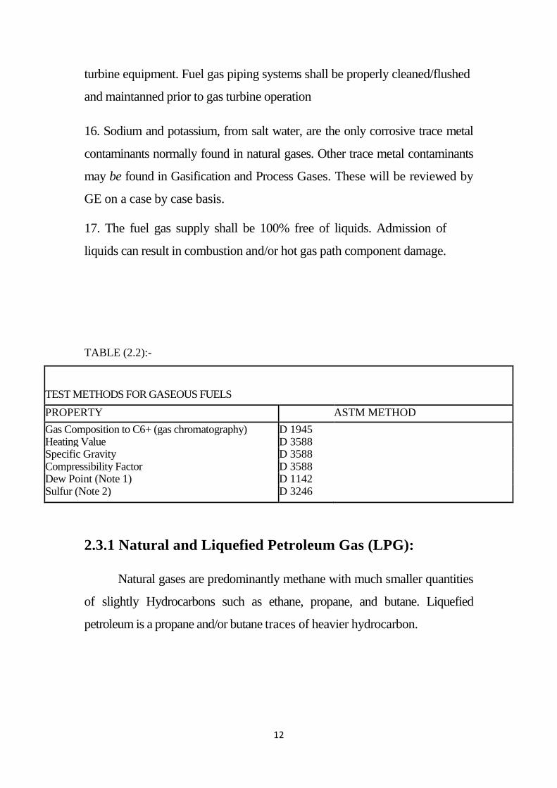
turbine equipment. Fuel gas piping systems shall be properly cleaned/flushed
and maintanned prior to gas turbine operation
16. Sodium and potassium, from salt water, are the only corrosive trace metal
contaminants normally found in natural gases. Other trace metal contaminants
may be found in Gasification and Process Gases. These will be reviewed by
GE on a case by case basis.
17. The fuel gas supply shall be 100% free of liquids. Admission of
liquids can result in combustion and/or hot gas path component damage.
TABLE (2.2):-
TEST METHODS FOR GASEOUS FUELS PROPERTY ASTM METHOD Gas Composition to C6+ (gas chromatography) D 1945 Heating Value D 3588 Specific Gravity D 3588 Compressibility Factor D 3588 Dew Point (Note 1) D 1142 Sulfur (Note 2) D 3246
2.3.1 Natural and Liquefied Petroleum Gas (LPG):
Natural gases are predominantly methane with much smaller quantities
of slightly Hydrocarbons such as ethane, propane, and butane. Liquefied
petroleum is a propane and/or butane traces of heavier hydrocarbon.
13
2.3.1.1Natural gas
Natural gases normally fall within the calorific heating value range
of 800 to-
2.3.1.2Liquefied Petroleum Gases:
1200 Btu per standard cubic foot. Actual calorific heating values are
dependent on the percentages of hydrocarbons and inert gases contained in the
gas. Natural gases are found in and extracted from underground reservoirs.
These "raw gases" may contain varying degrees of nitrogen, carbon dioxide,
hydrogen sulfide, and contain contaminants such as salt water, sand, and dirt.
Processing by the gas supplier normally reduces and/or removes these
constituents and contaminants prior to distribution. A gas analysis must be
performed to ensure that the fuel supply to the gas turbine meets the
requirements of this specification.
The heating values of Liquefied Petroleum Gases (LPG) normally fall
between 2300 and 3200 Btu/ SCF (LHV). Based on their high commercial
value, these fuels are normally utilized as a back—up fuel to the primary gas
fuel for gas turbines. Since LPG are normally stored in a liquid state, it is
critical that the vaporization process and gas supply system maintains the
fuel at a temperature above the minimum required to superheat value. Fuel
heating and heat tracing are required to ensure this.
2.3.2 Gasification Fuels:
Other gases that may be utilized as gas turbine fuel are those formed by
the gasification of coal, petroleum coke or heavy liquids. In general, the
heating values of gasification fuel are substantially lower than other fuel gases.
These lower heating value fuels result in the effective areas of the fuel
nozzles being larger than those utilized for fuels of higher heating values.
14
Gasification fuels are produced by either an Oxygen Blown or Air Blown
gasification process.
2.3.2.1Oxygen Blown Gasification:
The heating values of gases produced by oxygen-blown gasification fall
in the range of 200 to 400 BtuISCF. The Hydrogen (I-12
2.3.2.2Air Blown Gasification:
) content of these fuels
are normally above 30% by volume and have H2ICO mole ratio between 0.5 to
0.8. Oxygen-blown gasification fuels are often mixed with steam for thermal
NOx control, cycle efficiency improvement and/or power augmentation.
When utilized, the steam is injected into the combustor by an independent
passage. Due to the high hydrogen content of these fuels, oxygen-blown
gasification fuels are normally not suitable for Dry Low NOx (DLN)
applications. (See Table 2) The high flame speeds resulting from high hydrogen
fuels can result in flashback or primary zone re-ignition on DLN premixed
combustion systems. Utilization of these fuels shall be reviewed by GE
Gases produced by air blown gasification normally have heating values
between 100 and 150 BTU/ SCFH. The Hydrogen ( 11,) content of these
fuels can range from 8% to 20% by volume and have a 1-14C0 mole ratio of
0.3 to 3:1. The use and treatment of these fuels are similar to those identified
for oxygen-blown gasification.
For Gasification fuels, a significant part of the total turbine t low comes
from the fuel. In addition, for oxygen blown fuels there is a diluents addition
for NOx control. Careful integration of the gas turbine with the gasification
plant is required to assure an operable system. Due to the low volumetric
heating value of both oxygen an air blown gases, special fuel system and
fuel nozzles are required.
15
2.3.3 Process Gases:
Many chemical processes generate surplus gases that may be utilized
as fuel for gas turbines. (i.e. tailor refinery gases). These gases often
consisting of methane, hydrogen, carbon monoxide, and carbon dioxide that
are normal byproducts of petrochemical processes. Due to the hydrogen and
carbon monoxide content, these fuels have large rich to lean flammability
limits. These types of fuels often require inerting and purging of the gas turbine
gas fuel system upon unit shutdown or a transfer to a more conventional fuel.
When process gas fuels have extreme flammability limits such that the fuel
will auto-ignite at turbine exhaust conditions, a more "conventional" startup
fuel is required.
Additional process gases utilized as gas turbine fuels are those which are by-
products of steel production.
These are:-
1. Blast Furnace Gases (BFGs)
Blast Furnace Gases (BFGs), alone, have heating values below minima,
allowable:-limits: Gases must be blended with other fuel to raise the
heating value to above the required limit. Coke Oven and/or Natural Gases or
hydrocarbons such as propane or butane ‘can be utilized to accomplish this
2. Coke Oven Gases
Coke oven gases are high in II, and CH4 and may be used as fuel for non-Dry
Low NOx (DLN) combustion systems. These fuels often contain trace
amounts of heavy hydrocarbons, which when burned could lead to carbon
buildup on the fuel nozzles. The heavy hydrocarbons must be "scrubbed"
or removed from the fuel prior to delivery to the gas turbine.
16
3. CORER Gases
CORER gases are similar to oxygen blown gasified fuels and may be treated
as such. They are usually lower in H2 content and have lower heating values
than oxygen blown gasified fuels.
2.4 FUEL PROPERTIES
A. Heating Values
A fuel's heat of combustion, or heating value, is the amount of energy,
expressed in Btu•(British Thermal Unit), generated by the complete
combustion, or oxidation, of a unit weight of fuel'. The amount of heat
generated by complete combustion is a constant for a given combination of
combustible elements and compounds.
For most gaseous fuels, the heating value is determined by using constant
pressure, continuous type calorimeter. This is the industry standard. In these
units, combust:1_4,e substances are burned with oxygen under essentially
constant pressure conditions. In all fuels that contain hydrogen, water vapor is
a product of combustion, which impacts the heating value. In a bomb
calorimeter, the products of combustion are cooled to the initial temperature
and all of the water vapor formed during combustion is condensed. The result
is the HHV, or higher heating value, which includes the heat of vaporization
of water. The LHV, or lower heating value, assumes all products of
combustion including water remain in the gaseous state, and the water heat of
vaporization is not available.
B. Modified Wobble Index Range
While gas turbines can operate with gases having a very wide range of
heating values, the amount of variation that a single specific fuel system can
accommodate is much less. Variation in heating value as it affects gas
17
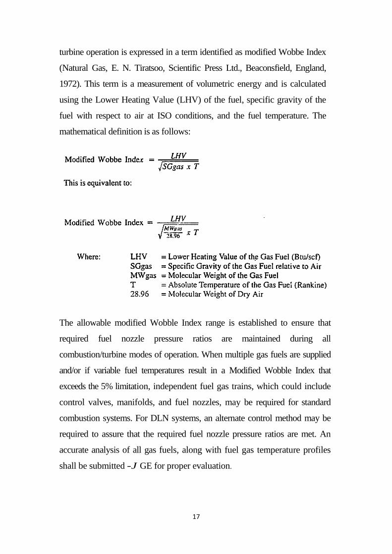
turbine operation is expressed in a term identified as modified Wobbe Index
(Natural Gas, E. N. Tiratsoo, Scientific Press Ltd., Beaconsfield, England,
1972). This term is a measurement of volumetric energy and is calculated
using the Lower Heating Value (LHV) of the fuel, specific gravity of the
fuel with respect to air at ISO conditions, and the fuel temperature. The
mathematical definition is as follows:
The allowable modified Wobble Index range is established to ensure that
required fuel nozzle pressure ratios are maintained during all
combustion/turbine modes of operation. When multiple gas fuels are supplied
and/or if variable fuel temperatures result in a Modified Wobble Index that
exceeds the 5% limitation, independent fuel gas trains, which could include
control valves, manifolds, and fuel nozzles, may be required for standard
combustion systems. For DLN systems, an alternate control method may be
required to assure that the required fuel nozzle pressure ratios are met. An
accurate analysis of all gas fuels, along with fuel gas temperature profiles
shall be submitted -J GE for proper evaluation.
18
C. Superheat Requirement
The superheat requirement is established to ensure that the fuel gas
supplied TFA the gas turbine is 100% free of liquids. Dependent on its
constituents, gas entrained liquids could cause degradation of gas fuel
nozzles, and for DLN applications, premixed flame flashbacks or re-ignition.
50°F of superheat is specified to provide enough margin to compensate for
temperature reduction due to the pressure drop across the gas fuel control
valves.
D. Flammability Ratio
Fuel gases containing hydrogen and/or carbon monoxide will have a
ratio of rich-to-lean flammability limits that is significantly larger than that of
natural gas. Typically, gases with greater than 5% hydrogen by volume fall
into this range and require a separate startup fuel. GE will evaluate the gas
analysis to determine the requirement for a start-up fuel.
Fuel gases with large percentages of an inert gas such as nitrogen or carbon
dioxide will have a ratio of rich—to—lean flammability limits less than that of
pure natural gas. Flammability ratios of less than 2.2to 1 as based on volume at
ISO conditions (14.696 psi and 59°F), may experience problems maintaining
stable combustion over the full operating range of the turbine
E. Gas Constituent Limits
Gas constituent limits are set forth to assure stable combustion through all
gas turbine loads and modes of operation. Limitations are more stringent for
Dry Low NOx combustion systems where "premixed" combustion is utilized.
Detailed gas analysis shall be furnished to GE for proper evaluation.
19
F. Gas Fuel Supply Pressure
Gas fuel supply pressure requirements are dependent on the gas turbine
model and combustion design, the fuel gas analysis and unit specific site
conditions. Minimum and maximum supply pressure requirements will be
furnished by GE as part of the unit proposal.
IV. CONTAMINANTS
Dependent on the type of fuel gas, the geographical location and the
forwarding means there is the potential for the "raw" gas supply to contain
one or more of the following contaminants: Water, salt water, Iron
sulfide, Scrubber oil or liquid, Compressor Lube oil, etc..
2.5 Assumption of calculation:- All data collected from the garri1,2 power station, department off
efficiency and planning, monthly reports.
-fuel comparison is between (LDO, HCGO).
-Averages are taken for one block by dividing by 4.
- Estimated base load for each block 90 MW(each block consists of 2GT
unit and 1 ST unit)
-the load calculation is base on 24 hours a day 320 for 1 year (subtract 45
days for maintenance work)
20
- 1 Block =30 MW * 3 unit * 24 hours * 320 days = 691200 MW output
- Operational cost using (fuel type) = consumption of fuel* fuel Price
-Kw.h price according to fuel=cost of fuel*consumption fuel / total sent energy
- Efficiency
- Heat rate = 1/ƞ
ƞ= total output(MW) / input(MW)
Since:
Input= ṁf
*caloric value of fuel
KW.hr price (SDG/KW.hr)= total cost/ Actual sent energy
-Auxiliary consumption = 0.02538*691200= 17543 MW
Total cost (operation cost , maintenance cost, fuel cost , depreciation cost , insurance ,
density LDO=1.215
Fuel price are ( 2179.481 SDG/ton for LDO , 331.32 SDG/ton for
Maintenance cost is increased by10%,20%,30%,40%,40% and 50% to meet
modifications
Auxiliary power consumption average calculated=2.538% of total generated load.
Total sent energy =total output – auxiliary consumption
21
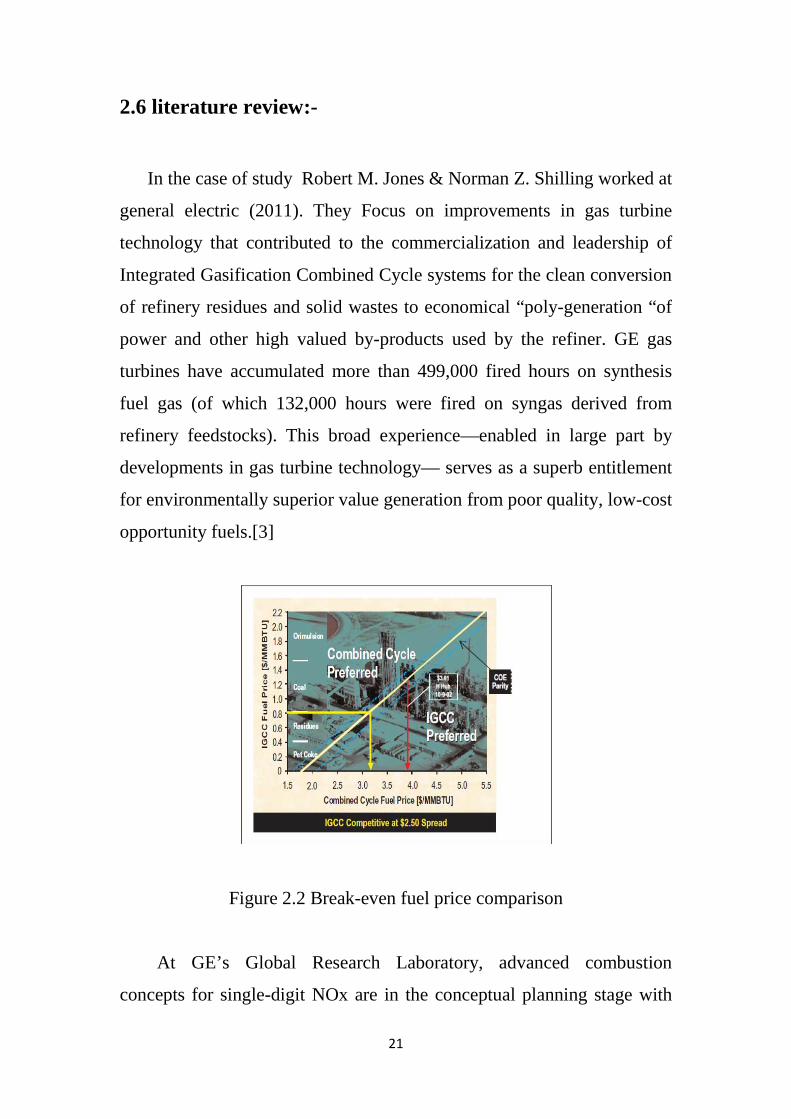
2.6 literature review:-
In the case of study Robert M. Jones & Norman Z. Shilling worked at
general electric (2011). They Focus on improvements in gas turbine
technology that contributed to the commercialization and leadership of
Integrated Gasification Combined Cycle systems for the clean conversion
of refinery residues and solid wastes to economical “poly-generation “of
power and other high valued by-products used by the refiner. GE gas
turbines have accumulated more than 499,000 fired hours on synthesis
fuel gas (of which 132,000 hours were fired on syngas derived from
refinery feedstocks). This broad experience—enabled in large part by
developments in gas turbine technology— serves as a superb entitlement
for environmentally superior value generation from poor quality, low-cost
opportunity fuels.[3]
Figure 2.2 Break-even fuel price comparison
At GE’s Global Research Laboratory, advanced combustion
concepts for single-digit NOx are in the conceptual planning stage with
22
promise for additional application to syngas and long term emissions
reduction. natural gas prices of $2.5 per MMBtu higher than IGCC fuel
prices, IGCC provides a cost of electricity equivalent to NGCC. Current
natural
gas pricing (e.g., Henry Hub-$3.91/MMBtu- HHV, 10/9/02) would
suggest that COE from
refinery-based IGCC plants fueled by low-cost opportunity fuels (e.g.,
residuals or pet coke)
should be significantly lower than NGCC plants with spot-market fuel
pricing. Contemporary IGCC plant designs are commercially viable with
refinery operations owing to their broad capability to use the opportunity
and low-value waste fuels.
Also in the report of Mr. Jeffrey Goldmeer, Ph.D. at ( 2014), made
studied for heavy liquid fuels, such as crude oil or heavy fuel oil can be
used for power generation, but these ash-bearing fuels are traditionally
only used on E-class turbines, in part because of the high levels of metal
contaminants. However, some crude oils have the potential to be used in
F-class turbines. One particular crude oil, Arabian Super Light (ASL),
has the potential to be used as a fuel on a heavy-duty gas turbine as ASL
has unique properties relative to other crude oils, including low levels of
vanadium. This paper presents a case study in GE’s fuel evaluation
process using the ASL as an example of the steps required to validate a
new fuel for use in a gas turbine. Using this process GE determined that
ASL is a viable fuel for use in F-class gas turbines, and concluded with a
successful field demonstration on a GE 7F gas turbine in Saudi Arabia.
This was a significant milestone as it was the first time that crude oil was
operated in an F-class gas turbine.[4]
Modern gas turbines are able to operate on a large range of
gas and liquid fuels, and the number of fuels these systems is able to
23
operate how best to use their domestic natural resources. In the case of
ASL, the evaluation process provided a positive result. Following the
successful completion of the ASL demonstration testing in December
2013, the customer fully commissioned the plant on ASL, becoming the
first F-class power plant to be able to operate on crude oil. This
evaluation of ASL was an important step for power generation in Saudi
Arabia as this fuel has been selected as the back-up fuel for multiple
combined cycle power plants, which include 27 GE 7F gas turbines. Once
all of these units are fully commissioned, they will provide more than 4.4
GW of power for Saudi Arabia.
Otherwise in the report of the total generation capacity in
Myanmar (2015) is 4,581MW, of which 3,044MW (66.4%) is from
hydropower. Only 33% of the population has access to electricity.
Myanmar needs substantially more generating capacity since its socio-
economic development is hampered by lack of electricity. Myanmar is
mapping a National Electricity Master plan to meet increasing demand,
setting its sights on boosting capacity from 4,581MW to over 27,000MW
in 2030. Myanmar plans to shift the focus from hydropower to other
energy sources, including coal, natural gas, solar, and wind power by
2030. High reliance on hydropower causes unstable supply, as the storage
in reservoirs shrinks during the hot season. The paper proposes an
optimum energy mix for Myanmar in line with common practice in
developing countries. Flexible internal combustion engines (ICEs) based
power plants offer excellent fuel efficiency and reliability. These gas-
based power plants are quick to respond, efficient and, can make
optimum use of available gas. The dual-fuel combustion engine power
plants can be optimized to initially run on cheap liquid fuel (HFO or
crude oil) and later use natural gas when it’s eventually tapped from the
proven reserves of 11Tcf. Such generating units have proved their worth
24
in meeting peaking and reserve requirements and in providing necessary
back-up for renewable energy that tends to be intermittent. The optimal
technology for each project must be chosen based on a feasibility study
specific to the project. This paper analyzes the life cycle costs of a dual
fuel combined cycle gas turbines and ICEs plants separately. Based on
the feasibility study, combustion engines based dual fuel plant has lower
total life-cycle cost than gas turbine power plant. Total saving in base
load operation is 92 Million USD over 4 years of liquid fuel operation
and 217 Million USD over the project lifetime. The dual fuel combustion
engine plants provide the best possible effect on HFO& gas mode, as well
as the lowest life-cycle costs when compared to gas turbine technologies.
Greater efficiency of ICE plants would also allow the same amount of
fuel to produce more electricity as gas turbines, thus reducing the impact
of restricted gas supplies in Myanmar.[5]
And also case was studied (H.E. von Doering, and M.B. Hilt)
in (2014) World events have highlighted the critical role that fuels play in
power production. The cost and availability of fuel are preeminent
planning considerations. Consequently, the ability of any prime mover to
burn a wide range of fuels-or fuels flexibility-continues to be of primary
importance.
GE heavy-duty gas turbines have operated successfully Burning
alternate gaseous fuels with heating values ranging from 11.2 to 116
MJ/m3 (300 to 3100 Btu/ft3 lower heating value (LHV). A listing of gas
turbines with alternate gaseous fuel capability by type of fuel, model
series, and year of shipment is presented.On the basis of single combustor
tests in the laboratory, the capability for successful operation with fuel
heating values as low as 4 MJ/mS (110 Btu/ft3) LHV has been
demonstrated. More recently GE initiated a program of extensive
25
analytical calculations to investigate the combustion characteristics of a
number of lower-heating-value fuels, typical of those produced by a fuel-
conditioning process. The analytical calculations were coupled with
atmospheric burner tests using a small scale diffusion flame burner.
Based upon the results of this study, full-scale single-burner and sector
tests were conducted in the Gas Turbine Development Laboratory to
confirm expected MS5000 and LM2500 engine performance. An
example of the benefits derived from this extensive program is the
finding that both the MS5000 and LM2500 gas turbines will operate
satisfactorily
While burning a 15.8 MJ/m3 (425 Btu/ft3) gas that comprised nearly 80
percent CO* by volume. In general, the only change required to the
standard combustion system is a modification of the gas fuel nozzle to
handle the increased volume of fuel. A variation in the heating value of
more than +20 percent could be tolerated while still maintaining adequate
combustor performance.
The selection of the type of liquid gas turbine fuel is important because
the fuel is generally the largest single annual cost item.[6]
Also (someone forms G.E company at 2009) the steady growth of
power demand in the Middle East continues
to drive governments, power authorities and independent power providers
to look for solutions to meet country as well as regional energy
requirements. To provide for these increasing energy
requirements, these organizations must cope with issues of fuel supplies
and cost. Fuel supply is further complicated when considering the global
competition for what could be
26
a local generation fuel and increasing environmental awareness. These
factors contribute to the region’s interests in the diversification of supply
and the potential in what may have been considered
margin fuels for generation. In addition, these factors contribute to a
greater interest to consider a diverse fuel spectrum allowing for increased
operational flexibility and cost control, with improved plant efficiency
and emissions characteristics.
Gas turbine based generation systems offer efficient energy
Conversion solutions for meeting the challenge of fuel diversity while
maintaining superior environmental performance. Combustion design
flexibility allows operators a broad spectrum of gas and liquid fuel
choices, including emerging synthetic choices. Gases include
and are not limited to ultra-low heating value process gas, syngas, ultra-
high hydrogen or higher heating capability fuels. Liquid fuels, considered
by some outside the Middle East as a “back up” fuel to natural gas, are a
mainstay for the region. This includes Heavy Fuel Oil, which is a
primary fuel for many power generation applications in the Middle East.
This paper will address the broad range of fuel options in the context of
proven, available technology and introduces product solutions tailored to
meet fuel flexibility demands expected by the larger generation
community.[7]

27
Chapter 3
28
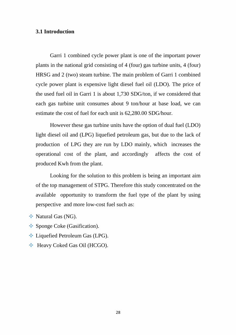
3.1 Introduction
Garri 1 combined cycle power plant is one of the important power
plants in the national grid consisting of 4 (four) gas turbine units, 4 (four)
HRSG and 2 (two) steam turbine. The main problem of Garri 1 combined
cycle power plant is expensive light diesel fuel oil (LDO). The price of
the used fuel oil in Garri 1 is about 1,730 SDG/ton, if we considered that
each gas turbine unit consumes about 9 ton/hour at base load, we can
estimate the cost of fuel for each unit is 62,280.00 SDG/hour.
However these gas turbine units have the option of dual fuel (LDO)
light diesel oil and (LPG) liquefied petroleum gas, but due to the lack of
production of LPG they are run by LDO mainly, which increases the
operational cost of the plant, and accordingly affects the cost of
produced Kwh from the plant.
Looking for the solution to this problem is being an important aim
of the top management of STPG. Therefore this study concentrated on the
available opportunity to transform the fuel type of the plant by using
perspective and more low-cost fuel such as:
Natural Gas (NG).
Sponge Coke (Gasification).
Liquefied Petroleum Gas (LPG).
Heavy Coked Gas Oil (HCGO).
29
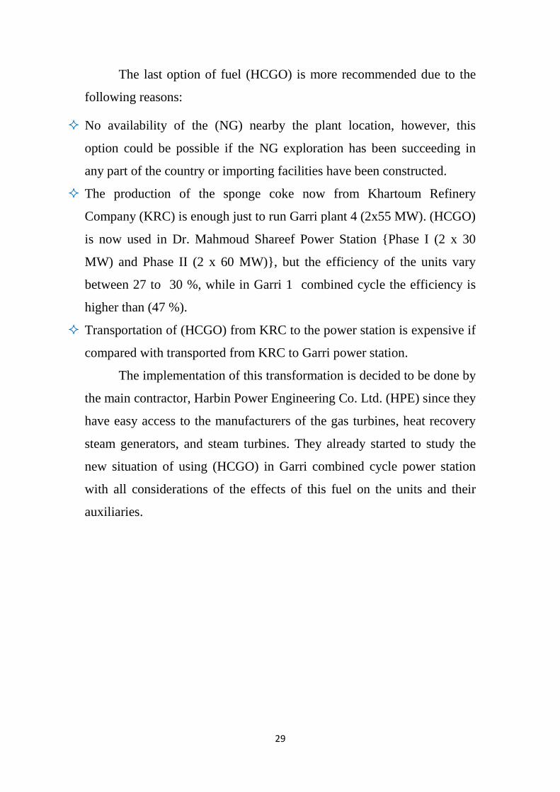
The last option of fuel (HCGO) is more recommended due to the
following reasons:
No availability of the (NG) nearby the plant location, however, this
option could be possible if the NG exploration has been succeeding in
any part of the country or importing facilities have been constructed.
The production of the sponge coke now from Khartoum Refinery
Company (KRC) is enough just to run Garri plant 4 (2x55 MW). (HCGO)
is now used in Dr. Mahmoud Shareef Power Station {Phase I (2 x 30
MW) and Phase II (2 x 60 MW)}, but the efficiency of the units vary
between 27 to 30 %, while in Garri 1 combined cycle the efficiency is
higher than (47 %).
Transportation of (HCGO) from KRC to the power station is expensive if
compared with transported from KRC to Garri power station.
The implementation of this transformation is decided to be done by
the main contractor, Harbin Power Engineering Co. Ltd. (HPE) since they
have easy access to the manufacturers of the gas turbines, heat recovery
steam generators, and steam turbines. They already started to study the
new situation of using (HCGO) in Garri combined cycle power station
with all considerations of the effects of this fuel on the units and their
auxiliaries.
30
The table below summarized the financial analysis and findings
due to the planned modification Table (3.1) :-
Characteristic Using LDO Using HCGO
Unit consumption per
day –ton
- -
Fuel cost per day - -
Availability - -
Kwh cost - -
3.2 Option – Use (HCGO) in Garri Power Station:
3.2.1 Description: This option is mainly based on using the (HCGO) as fuel in
combination with (LDO) (which will be used only in start-up and
shut-down) of gas turbine units in Garri combined cycle power
plant.
This option requires some modifications and additional
systems to be installed such as heating system, fuel treatment
system, filtration skid, etc.
3.3Liquid Fuel System
General
When liquid fuel oil is selected for gas turbine operation this system
will pump fuel from the fuel oil storage tank by fuel forwarding pump.
The discharge of fuel oil forwarding pump go to a low-pressure filtration
system (duplex filter ) and regulate pressure by regulating valve before go
31
to fuel oil stop valve. When ignition permissive (purge sequence
complete and turbine speed at 18%) fuel oil stop valve open the oil to the
main fuel oil pump, driven by accessory gear, to boost the pressure of
fuel oil before going to high-pressure filter and flow divider
consequently. Flow divider divides equal fuel oil flow to each of the ten
combustion chambers. Fuel oil flow will be at the proper pressure and
flow rate to meet all of the starting, acceleration and loading requirements
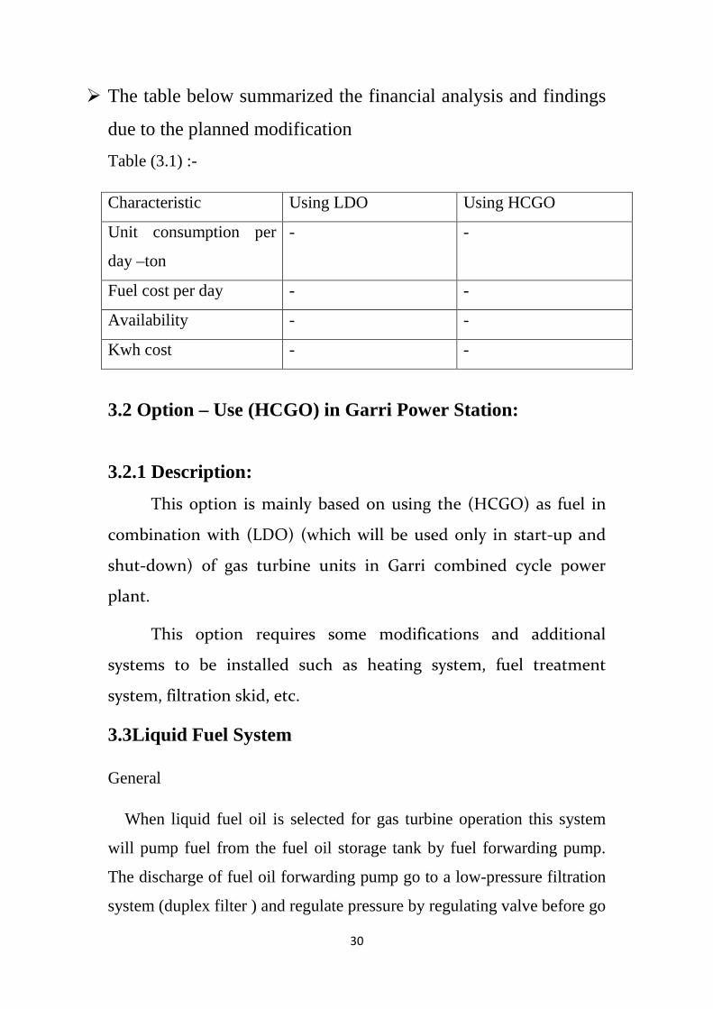
of gas turbine operation.[8]
Function description of
the fuel oil system:
Low-pressure filter
Fuel oil at low
pressure, from the fuel
forwarding system, is
filtered by the low
pressure (primary) oil
filter, before passing through the solenoid.
Fig 3.1 Duplex filter
operated fuel stop valve VS 1 and entering the fuel pump. The low
pressure is mounted near the accessory base and consist of 5 microns,
pleated paper element with oversize contamination capacity. Therefore,
clean fuel is normally supplied to the turbine system, however, the low-
pressure filter will prevent any contaminants that might be in the
the system from passing through and damaging or
interfering with the proper functioning of the fuel stop valve and the fuel
pump
Duplex
Vent
Transfer
Drain
Filling
32
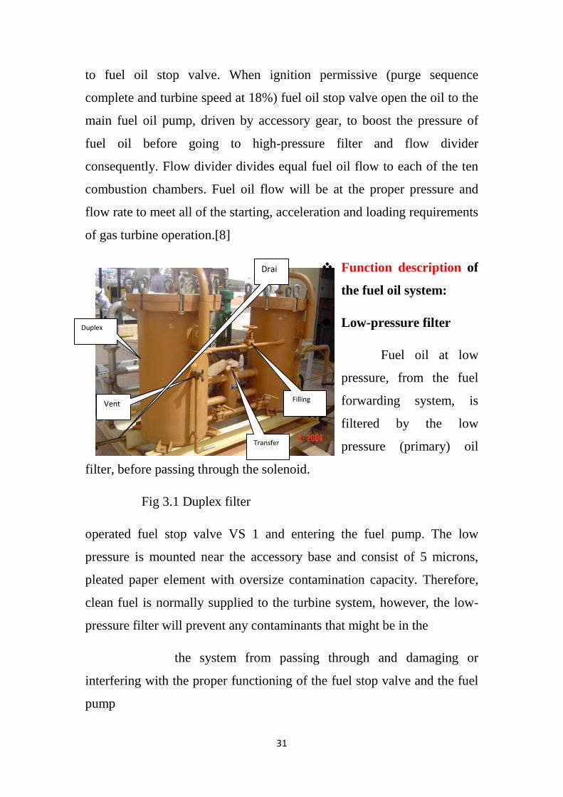
.
Before the low-
pressure filter, there is a
relief valve for each side of
the filter which protects the
supply circuit against
overpressures.
Fig 3.2 relief valve
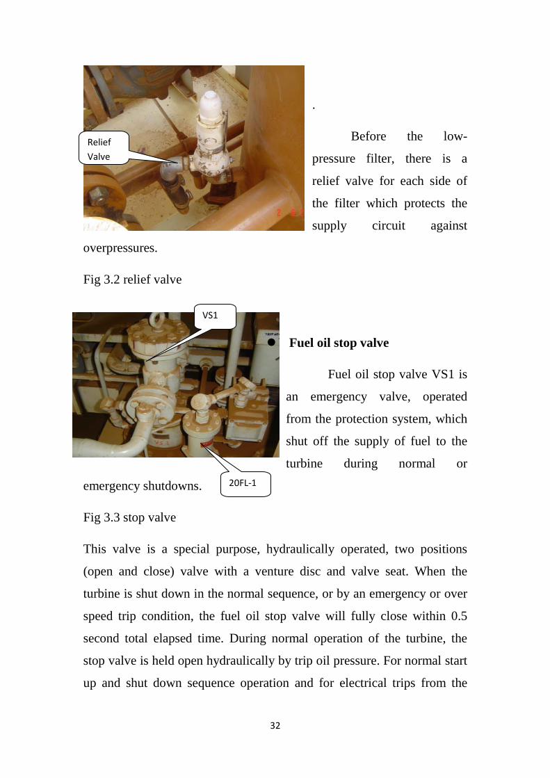
Fuel oil stop valve
Fuel oil stop valve VS1 is
an emergency valve, operated
from the protection system, which
shut off the supply of fuel to the
turbine during normal or
emergency shutdowns.
Fig 3.3 stop valve
This valve is a special purpose, hydraulically operated, two positions
(open and close) valve with a venture disc and valve seat. When the
turbine is shut down in the normal sequence, or by an emergency or over
speed trip condition, the fuel oil stop valve will fully close within 0.5
second total elapsed time. During normal operation of the turbine, the
stop valve is held open hydraulically by trip oil pressure. For normal start
up and shut down sequence operation and for electrical trips from the
Relief Valve
VS1
20FL-1
33
control panel, an elector hydraulic trip servo valve shut off the hydraulic
oil flow to the fuel oil stop valve hydraulic cylinder. The spring in the
fuel oil stop valve then overcomes the oil pressure and closes the valve.
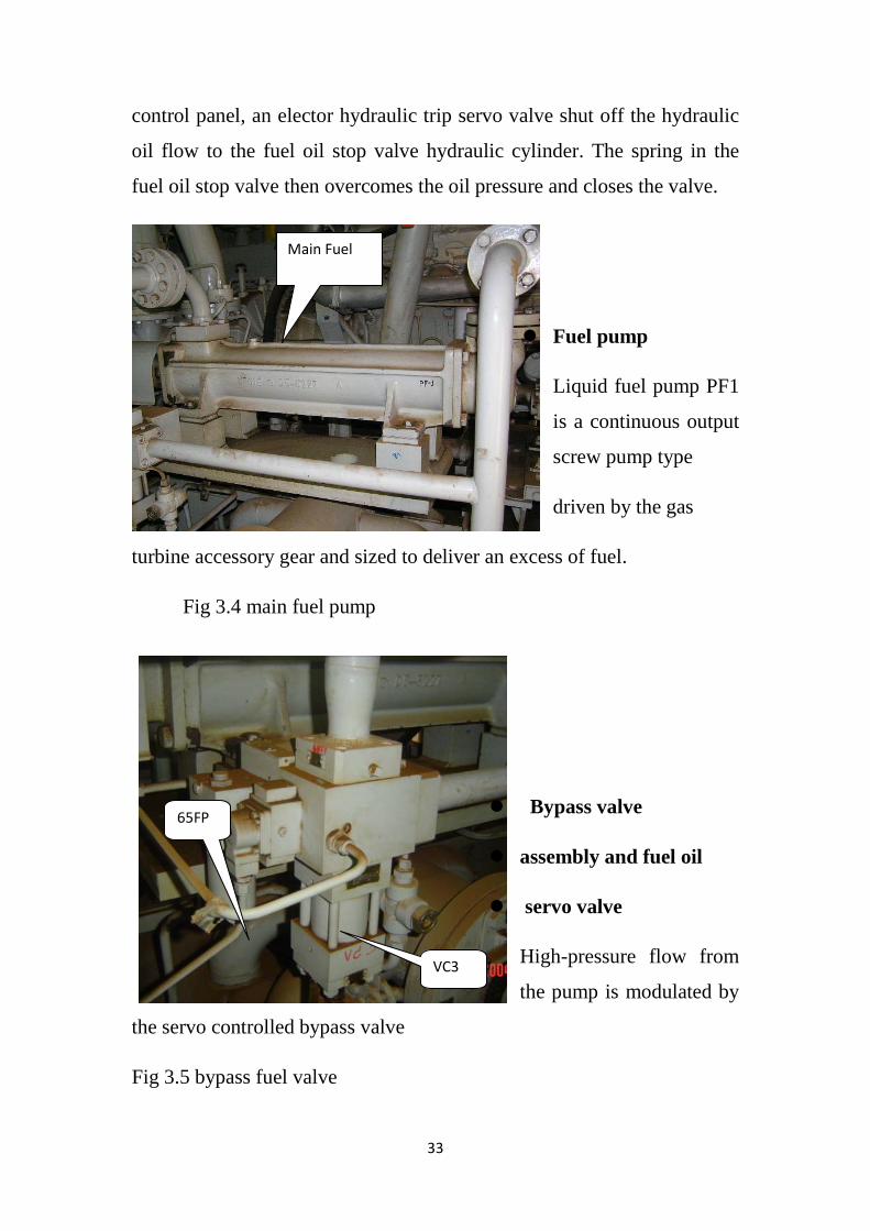
Fuel pump
Liquid fuel pump PF1
is a continuous output
screw pump type
driven by the gas
turbine accessory gear and sized to deliver an excess of fuel.
Fig 3.4 main fuel pump
Bypass valve
assembly and fuel oil
servo valve
High-pressure flow from
the pump is modulated by
the servo controlled bypass valve
Fig 3.5 bypass fuel valve
Main Fuel
VC3
65FP
34
assembly VC3. Components of this assembly include the bypass valve
body electro-hydraulic servo valve 65FP, the electro-hydraulic cylinder,
and relief valve VR4. this bypass valve is connected between the inlet
and discharge sides of the fuel oil pump and meters the flow of fuel to the
turbine by subtracting excess fuel delivered by the pump and bypassing it
back to the pump inlet.
The servo valve 65 FP controls the bypass valve stroke
according to the different requirement and the sensed fuel flow. If the fuel
requirement exceeds the actual oil flow, the bypass valve closes to
increase the net oil flow to the turbine. The servo valve uses high-
pressure hydraulic oil (cleansed of the contaminant by a metal filter FH3)
to actuate the hydraulic cylinder and thus position the bypass valve. The
FH3 filter has a delta p indicator to show filter dirty.
Pressure relief valve VR4
Installed on the fuel oil bypass valve assembly, is also
connected by piping between the discharge and inlet side of the fuel
pump. Its function is to protect the fuel pump against possible damage
from excessive pressure.
35
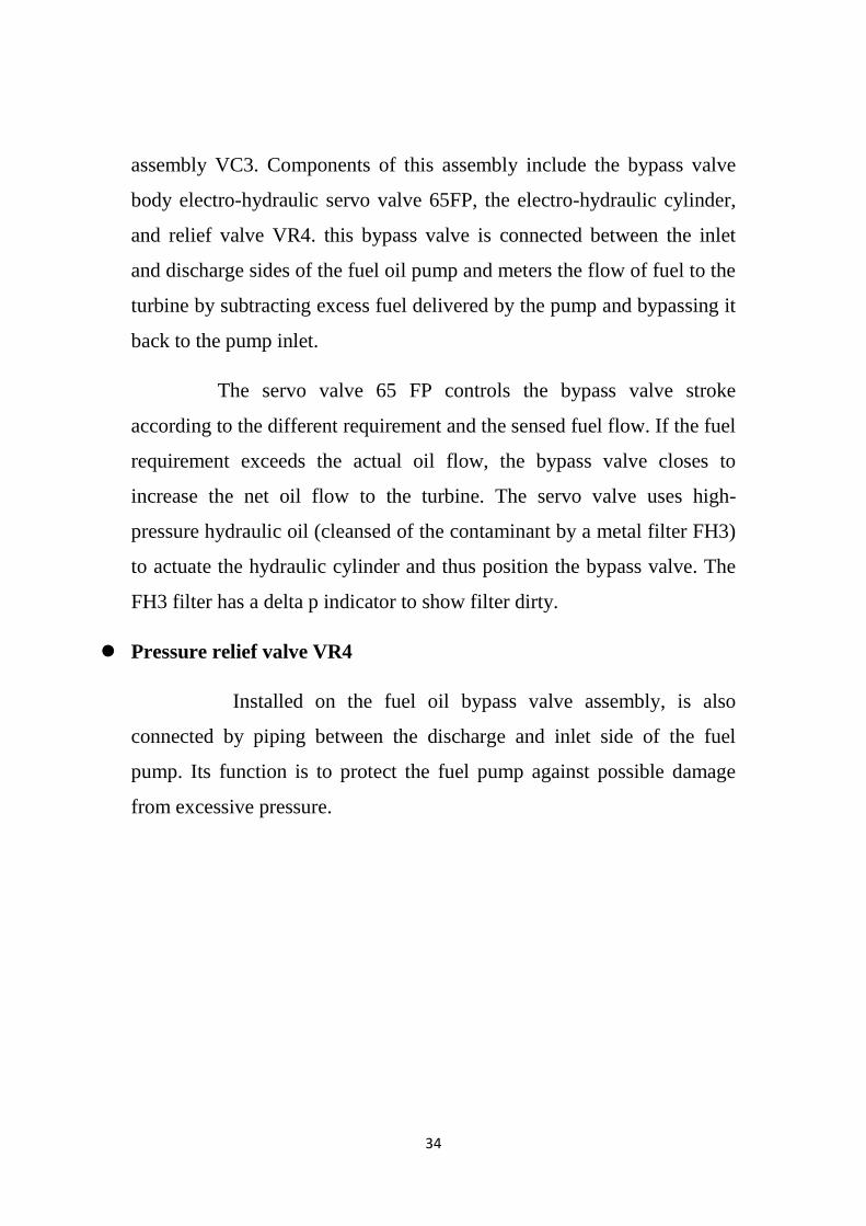
High-pressure oil filter
Fuel oil at pump discharge
pressure passed through the high
pressure (secondary) fuel filter as it
flows from the fuel pump to the flow
divider. This filter helps to assure that
contaminants such as pipe scale are
retained and prevented from entering
Fig 3.6 High pressure filter
the flow divider. Five microns pleated paper element provides filtration.
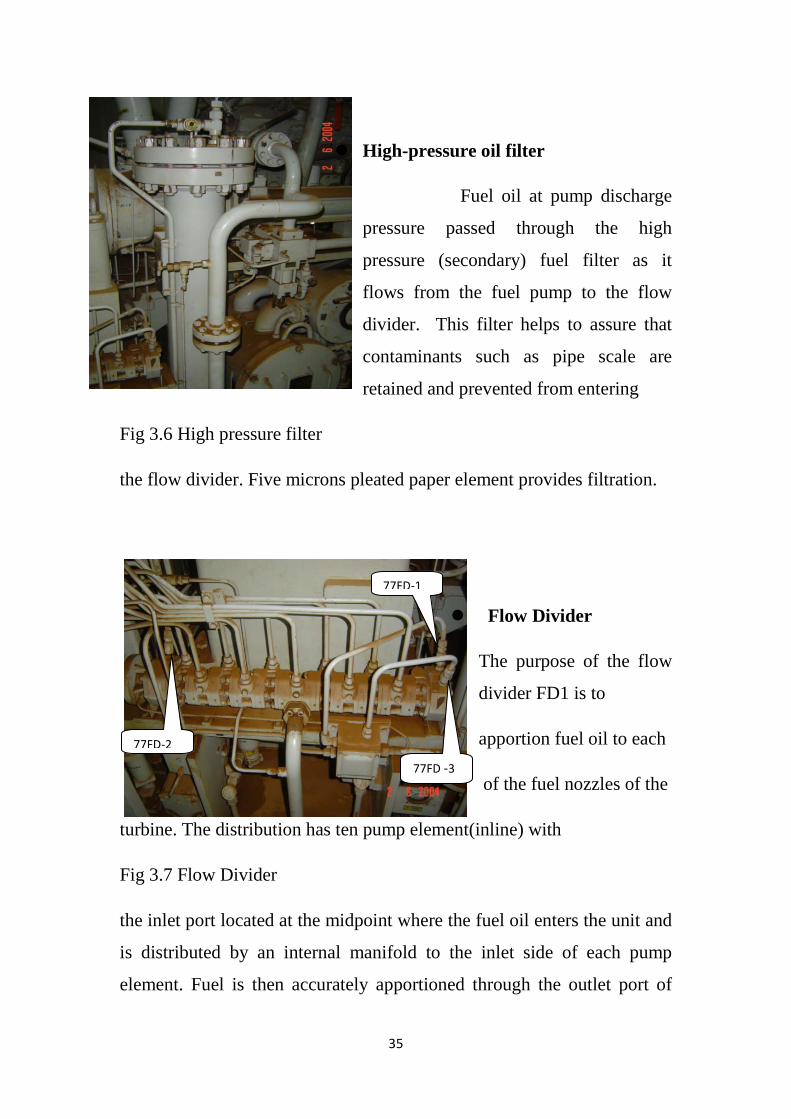
Flow Divider
The purpose of the flow
divider FD1 is to
apportion fuel oil to each
of the fuel nozzles of the
turbine. The distribution has ten pump element(inline) with
Fig 3.7 Flow Divider
the inlet port located at the midpoint where the fuel oil enters the unit and
is distributed by an internal manifold to the inlet side of each pump
element. Fuel is then accurately apportioned through the outlet port of
77FD -3
LF HP
Filter 77FD-1
77FD-2

36
each pump element to a corresponding turbine fuel nozzle. The flow from
each pump element is proportional to the speed at which the unit
operates.
Each of the pump element consists of two equal size gear
rotating in a closely fitted case. The driving gear and shafts are
interconnected by splined coupling. A gear indicator, located in each
faceplate, is connected to each end drive shaft. The operation is self-
sustaining by the flow of fuel oil through the flow divider.
The speed of flow divider pumping elements is directly
proportional to the flow delivered to the combustion chamber. Three
magnetic picks up assemblies 77FD-1, 77FD-2, and 77FD-3, fitted to the
flow divider, produce the flow feedback signal at a frequency
proportional to fuel flow delivered to the combustion chambers. This
signal is fed to the SPEED TRONIC where it is used in the fuel control
system.
The pickup adapters are located on the flow divider. The face
plate at each end of the unit has a scaling nut and stud located in the
threaded hold provide for the connection of magnetic pickup.
The pickup sensor consists of a permanent magnet,
surrounded by the coil in a hermetically sealed, externally threaded metal
case. A lock nut is provided on the case for setting the clearance between
the pickup and the flow divider gear element. Hermetically sealed pickup
leads are of sufficient length to reach to the junction box.
The magnetic flux in the pickups changes with the distance of
the pickup tip to the gear element surface. This creates an alternating
voltage output of the magnetic pickups as the gear element passed
beneath the pickup tip.
37
Flow divider pickups 77FD-1,77FD-2 and 77FD-3 pick up the
flow divider speed signal which is the feedback signal in the outer control
loop. The speed of the flow divider is the direct measure of the oil flow
through it and to the turbine fuel nozzle in the combustion chambers.
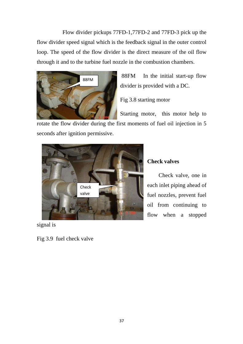
88FM In the initial start-up flow
divider is provided with a DC.
Fig 3.8 starting motor
Starting motor, this motor help to
rotate the flow divider during the first moments of fuel oil injection in 5
seconds after ignition permissive.
Check valves
Check valve, one in
each inlet piping ahead of
fuel nozzles, prevent fuel
oil from continuing to
flow when a stopped
signal is
Fig 3.9 fuel check valve
88FM
Check valve
38
given. This result in a clean cut off of fuel to nozzles.
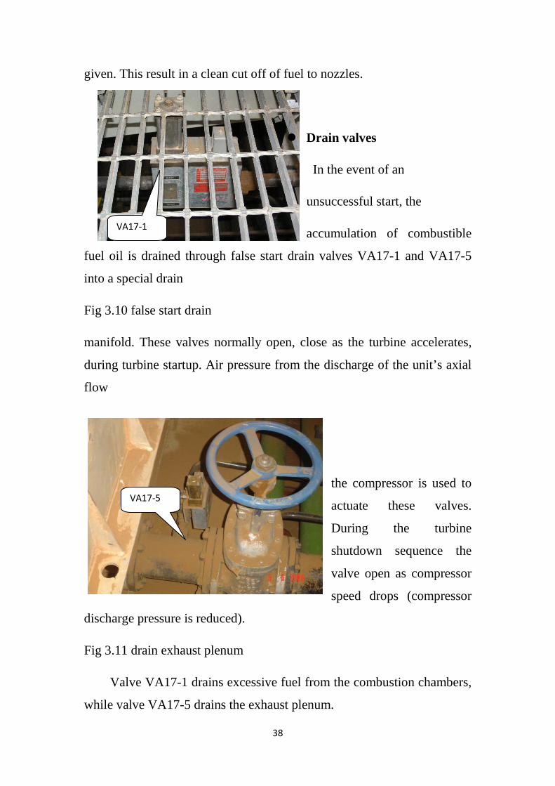
Drain valves
In the event of an
unsuccessful start, the
accumulation of combustible
fuel oil is drained through false start drain valves VA17-1 and VA17-5
into a special drain
Fig 3.10 false start drain
manifold. These valves normally open, close as the turbine accelerates,
during turbine startup. Air pressure from the discharge of the unit’s axial
flow
the compressor is used to
actuate these valves.
During the turbine
shutdown sequence the
valve open as compressor
speed drops (compressor
discharge pressure is reduced).
Fig 3.11 drain exhaust plenum
Valve VA17-1 drains excessive fuel from the combustion chambers,
while valve VA17-5 drains the exhaust plenum.
VA17-1
VA17-5
EXH. Plenum
39
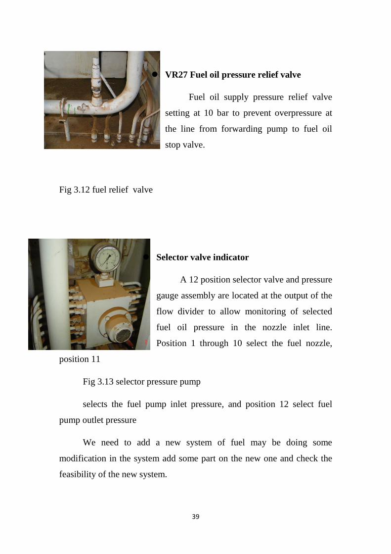
VR27 Fuel oil pressure relief valve
Fuel oil supply pressure relief valve
setting at 10 bar to prevent overpressure at
the line from forwarding pump to fuel oil
stop valve.
Fig 3.12 fuel relief valve
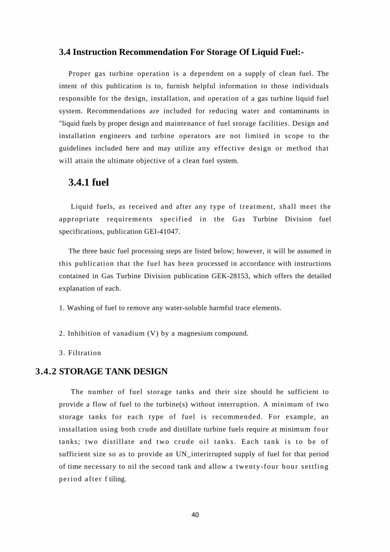
Selector valve indicator
A 12 position selector valve and pressure
gauge assembly are located at the output of the
flow divider to allow monitoring of selected
fuel oil pressure in the nozzle inlet line.
Position 1 through 10 select the fuel nozzle,
position 11
Fig 3.13 selector pressure pump
selects the fuel pump inlet pressure, and position 12 select fuel
pump outlet pressure
We need to add a new system of fuel may be doing some
modification in the system add some part on the new one and check the
feasibility of the new system.
40
3.4 Instruction Recommendation For Storage Of Liquid Fuel:-
Proper gas turbine operation is a dependent on a supply of clean fuel. The
intent of this publication is to, furnish helpful information to those individuals
responsible for the design, installation, and operation of a gas turbine liquid fuel
system. Recommendations are included for reducing water and contaminants in
"liquid fuels by proper design and maintenance of fuel storage facilities. Design and
installation engineers and turbine operators are not limited in scope to the
guidelines included here and may utilize any effective design or method that
will attain the ultimate objective of a clean fuel system.
3.4.1 fuel
Liquid fuels, as received and after any type of t reatment , shal l meet the
appropriate requirements specif ied in the Gas Turbine Division fuel
specifications, publication GEI-41047.
The three basic fuel processing steps are listed below; however, it will be assumed in
this publication that the fuel has been processed in accordance with instructions
contained in Gas Turbine Division publication GEK-28153, which offers the detailed
explanation of each.
1. Washing of fuel to remove any water-soluble harmful trace elements.
2. Inhibition of vanadium (V) by a magnesium compound.
3. Fil trat ion
3.4.2 STORAGE TANK DESIGN
The number of fuel storage tanks and their size should be sufficient to
provide a flow of fuel to the turbine(s) without interruption. A minimum of two
storage tanks for each type of fuel i s recommended. For example, an
installation using both crude and distillate turbine fuels require at minimum four
tanks; two di s t i l la te and two c r ud e o i l t a n ks . E ach t a n k i s t o b e o f
sufficient size so as to provide an UN_interirrupted supply of fuel for that period
of time necessary to nil the second tank and allow a twenty-four hour se t t l ing
per iod a f te r f tiling.
41
If three tanks are used, each should provide sufficient fuel for twenty-four hours of
operation. While fuel is being pumped from one tank, fuel in the second could be
settling and the third tank could be in process of being filled.
I t should be s t ressed tha t these a re minimum recommendations; larger tank
volumes provide a grea ter margin between switching of tanks.
With fuels which require washing, the use of a total certification tank is
recommendeded. Washed and inhibited fuel goes to this tank first. It is sampled
to verify that fuel treatment is satisfactory. Acceptable fuel can then be
de l ivered to the main storage tank and unsatisfactory fuel may be rewashed.
There may be instances, however, where another handling of unsatisfactory fuel is
required.
Certification tanks prevent improperly washed fuel from contaminating a
larger main storage tank. The size of the certificationation tank is determined by
the specific operation and available manpower. A. tank which may be f i l l ed in
eight hours is a reasonable size. After the tank is filled, the fuel quality is
checked and acceptable fuel routed to the storage tank. While forwardin this fuel
to the next station, consideration must be given to the fuel washing
equipment since a period of t ime exists when the washed fuel has no place to
go. Fuel washing system shutdown or a diversion of the washed fuel to the raw
storage tank will then occur. Two certification tanks are recommended enabling
continuous flow and keeping the washing equipment at the minimum size.
Initially, fuel being delivered to a storeage tank should pass through a
screen or coarse filter to remove any large particles. Inlet piping to the storage
tank should be eighteen inches (forty-six centimeters) minimum above the bottom
of the tank. Baffling at the point of fuel entry is desirable. The i ncomin g
s t r eam o f fue l sh ou ld no t be directed toward the bottom of the tank or done in
such a way as to stir up any material s e t t l ed on t he t ank bo t t o m. A ve loc i t y
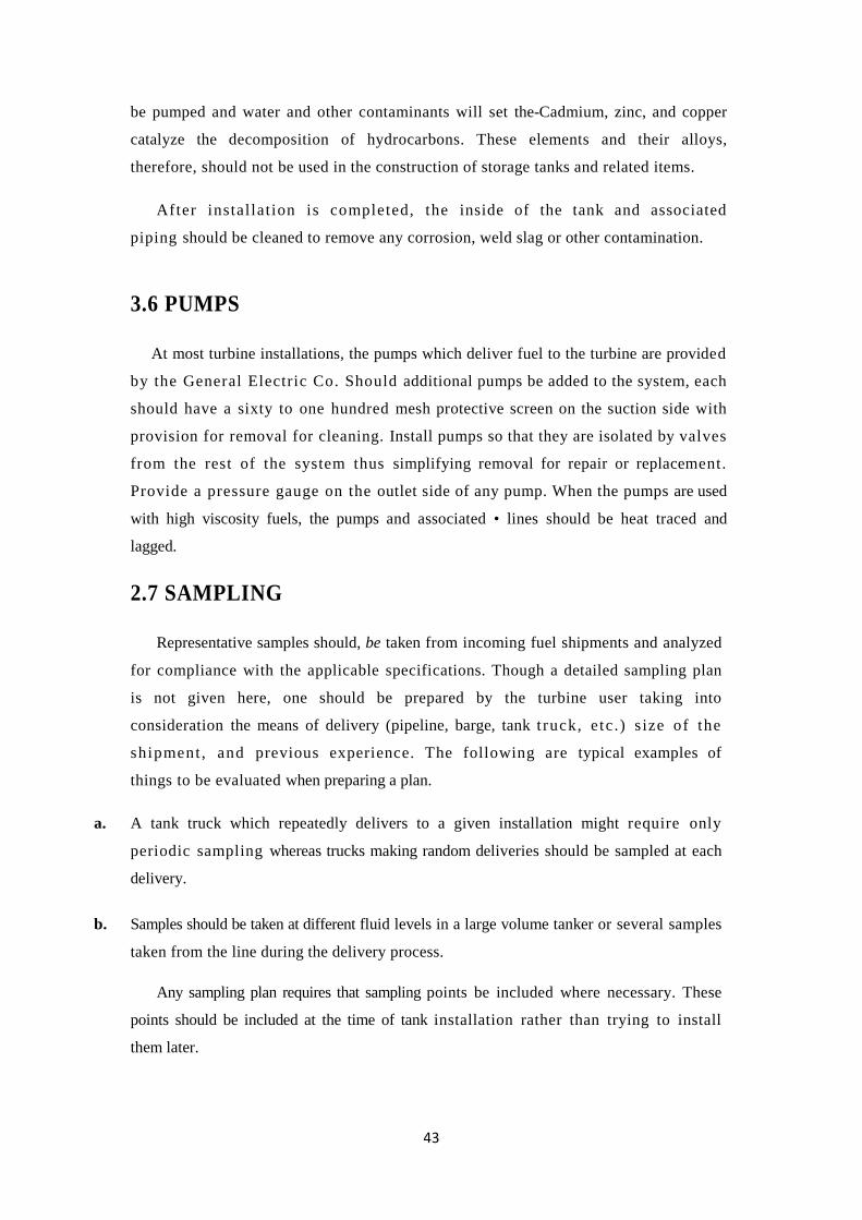
diffuser; shown in Figure I, can be used to minimize the jet effect of incoming
fuel.
Use a floating suction in the fuel line to the turbine such as shown in Figure3.1,
"Inlet Diffuser and Floating Suction". Limit the suction. Travel so that the inlet is
never less than eighteen inches from the tank bottom.
42
NOTE:-
- Fue l mus t not be pumped f rom the bottom of the storage tank.
-Any recirculat ion of fuel back to a storage tank must be done in a manner that
will cause minimum agitation of fuel in the tank. The return line should deliver the
fuel at a location removed from the floating suction and in a way that will not stir
up any material settled at the bottom of the tank.
3.5 STORAGE TANK OPERATIONAL MAINTENANCE
After filling a tank or adding additional fuel to it, allow a twenty-four hour
settling period before taking fuel from this tank.
NOTE:-
Under no circumstance should fuel be pumped into a tank at
the same time that it is being pumpeded out. Initially, drain water and any other
sediment from storage tanks once per day. After experience has been
established with a given fuel and fuel source, the frequency of draining may be
decreased at the discretion of the operator. The water removed must be
disposed of in a manner that meets local environmental regulations.
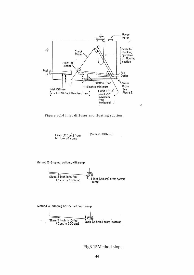
Storage tank bottoms should slope to an area from which water and other
settled ma te r i a l can be removed . Three such configurations are shown on
Figure3.2, "Tank Bottom Configurations".
Horizontal cylindrical tanks should be sloped at least two inches in ten
feet (5 cm in 3 m) so that water will collect in one end where it can be removed by a
sump pump or, if the tank is above ground, by a drain. If possible, a sump should be
placed at the low end of the tank so that water removal can be complete.
For fuels that are highly volatile and have a low flash, point, it may be
desirable to use a f loating roof on the tank. This reduces the fire hazard and
minimizes loss by evaporation. If used, there should be a fixed roof over the floating
top designed so that there will be the minimum entrance of rain and condensation.
When tanks are intended to store high viscosity fuels, such as residuals, a
means of heating must be provided to keep viscosity low enough so that the fuel may
43
be pumped and water and other contaminants will set the-Cadmium, zinc, and copper
catalyze the decomposition of hydrocarbons. These elements and their alloys,
therefore, should not be used in the construction of storage tanks and related items.
After instal lat ion is completed, the inside of the tank and associated
piping should be cleaned to remove any corrosion, weld slag or other contamination.
3.6 PUMPS
At most turbine installations, the pumps which deliver fuel to the turbine are provided
by the General Electric Co. Should additional pumps be added to the system, each
should have a sixty to one hundred mesh protective screen on the suction side with
provision for removal for cleaning. Install pumps so that they are isolated by valves
from the rest of the system thus simplifying removal for repair or replacement.
Provide a pressure gauge on the outlet side of any pump. When the pumps are used
with high viscosity fuels, the pumps and associated • lines should be heat traced and
lagged.
2.7 SAMPLING
Representative samples should, be taken from incoming fuel shipments and analyzed
for compliance with the applicable specifications. Though a detailed sampling plan
is not given here, one should be prepared by the turbine user taking into
consideration the means of delivery (pipeline, barge, tank t ruck, e tc . ) s ize of the
shipment , and previous experience. The following are typical examples of
things to be evaluated when preparing a plan.
a. A tank truck which repeatedly delivers to a given installation might require only
periodic sampling whereas trucks making random deliveries should be sampled at each
delivery.
b. Samples should be taken at different fluid levels in a large volume tanker or several samples
taken from the line during the delivery process.
Any sampling plan requires that sampling points be included where necessary. These
points should be included at the time of tank installation rather than trying to install
them later.
44
e
Figure 3.14 inlet diffuser and floating suction
Fig3.15Method slope

45
.
Chapter 4
46
4.1 Description of system modification:-
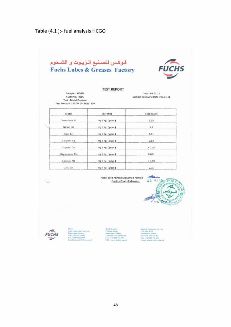
According to the HCGO fuel analysis report (show all tables ), of
HCGO with low content of Na, K, V and Ash accord with gas turbine
criterion and requirement for directly using, it does not need extra
treatment system to clean these impurities. But for high viscosity oil
under normal temperature, it is necessary to reduce its viscosity to meet
the requirement of the gas turbine.
The modification divides into gas turbine body modification and
forwarding system modification. The modification proposal of
forwarding system is submitted here:
1-According to the requirement of the owner, change three of four
existing LDO tanks into HCGO tanks. One of the three HCGO tanks needs
to be added a heater. The insulation of the oil tank is unnecessary. The
oil supply pipe and oil return pipe of HCGO need insulation
2- At present, the LDO pipeline from oil tanks to pump house adopts the
dual main piping scheme. We plan to change it into a single main piping
scheme. One pipe is for LDO, and another is for HCGO.
3-There are 6 sets of LDO pumps in pump hours now. Only 2 pumps are
needed for the actual operation of 4 units. It is recommended to keep 3
sets of LDO pumps, two for use, and one for standby. The 3 dismantled
pumps are kept as spare parts
4- Reinstall 3 sets of HCGO pumps on the basis of dismantled LDO
pumps, two for use and one for standby. The purpose of this is to make
the most use of pump house, so that the pump house does not have to
47
be rebuilt and MCC cabinet also does not have to be added, just need to
replace some components.
5-The LDO pipeline from the pump house to gas turbine adopts dual
main piping scheme at present. One pipe should be kept for LDO oil
supply; another is used for HCGO oil return. Add an extra pipe for HCGO
oil supply
6-The source of heat for heating HCGO is bleeding steam from boiler
high-pressure steam drum. Originally, it was used for hearing LPG.
Connect a steam pipe from bleeding steam pipe to gas turbine head for
heating HCGO, so that the HCGO can be met requirement of gas turbine
7- The heat exchange skid, filtration skid and switching skid of HCGO are
placed on the right of the gas turbine, besides existing forwarding filter
skid. The modularization design can shorten the construction schedule
on the site.
8- Set an oil return tank for HCGO flushing beside existing waste oil pool
and pump the oil back to HCGO tank. The oil tank should be set
underground for oil return.
9- Merge the control system of HCGO pumps into ABB control system.
48
Table (4.1 ):- fuel analysis HCGO
49
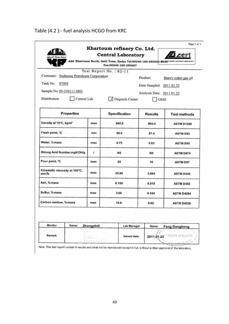
Table (4.2 ):- fuel analysis HCGO from KRC
50
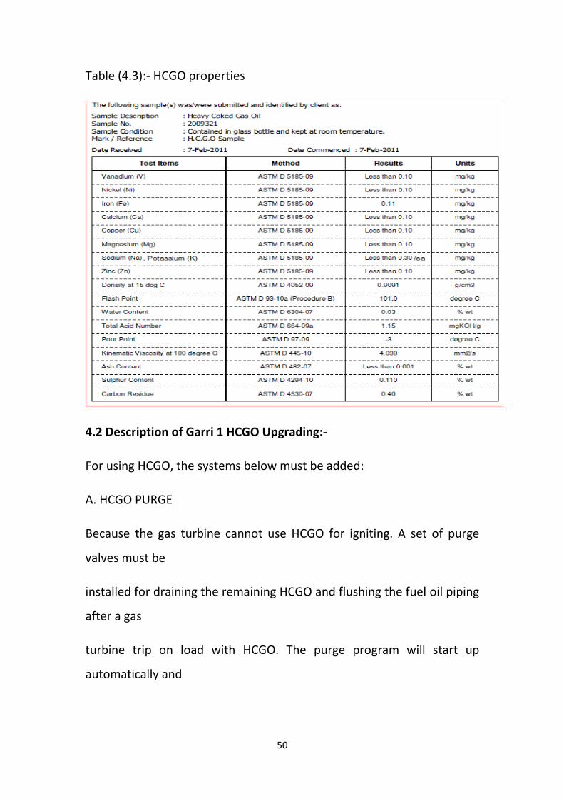
Table (4.3):- HCGO properties
4.2 Description of Garri 1 HCGO Upgrading:-
For using HCGO, the systems below must be added:
A. HCGO PURGE
Because the gas turbine cannot use HCGO for igniting. A set of purge
valves must be
installed for draining the remaining HCGO and flushing the fuel oil piping
after a gas
turbine trip on load with HCGO. The purge program will start up
automatically and
51
purge piping after a trip until the fuel line contains100% of diesel. A sight
glass
allows a visual check.
The purge valves involve a 10 ways hydraulic valve VP1 with the position
switch, control
solenoid valve 20PF-100, control button 43FUOP, new hydraulic oil
piping, and new
drain piping. New drain tank and the new pump are necessary to reuse
the drain oil.
B.OTHER PART
New high-pressure atomization air pump, new fuel flow divider, new
filter cores and
other equipment must be changed to meet the requirement of the gas
turbine using HCGO.
Because the viscosity of HCGO is high, it is prone to block the filter and
flower
divider and difficult to be atomized.
C.HCGO SUPPLY SYSTEM
- HCGO FORWARDING PUMPS
The HCGO pumps skid supplies fuel oil with sufficient pressure to
overcome the

52
the pressure drop of the various components from the oil tank to the GT
inlet and meet
the pressure requirement of GT.
Fig 4.1 HCGO forwarding pumps module sketch
D. FORWARDING HEATER MODULE
Heater skid heats the HCGO to reduce its viscosity to easy atomize and
combust. It
mainly includes 2 plate heat exchangers(1 operate, 1 standby)and 1
temperature
control valve to make HCGO reach proper temperature.

53
Fig 4.2 HCGO forwarding heater module sketch
E.HCGO FILTER MODULE
This module can filter the HCGO and make it reach the cleanliness
requirement of
liquid fuel specification GEI-41047.
Fig 4.3 HCGO filter module sketch

54
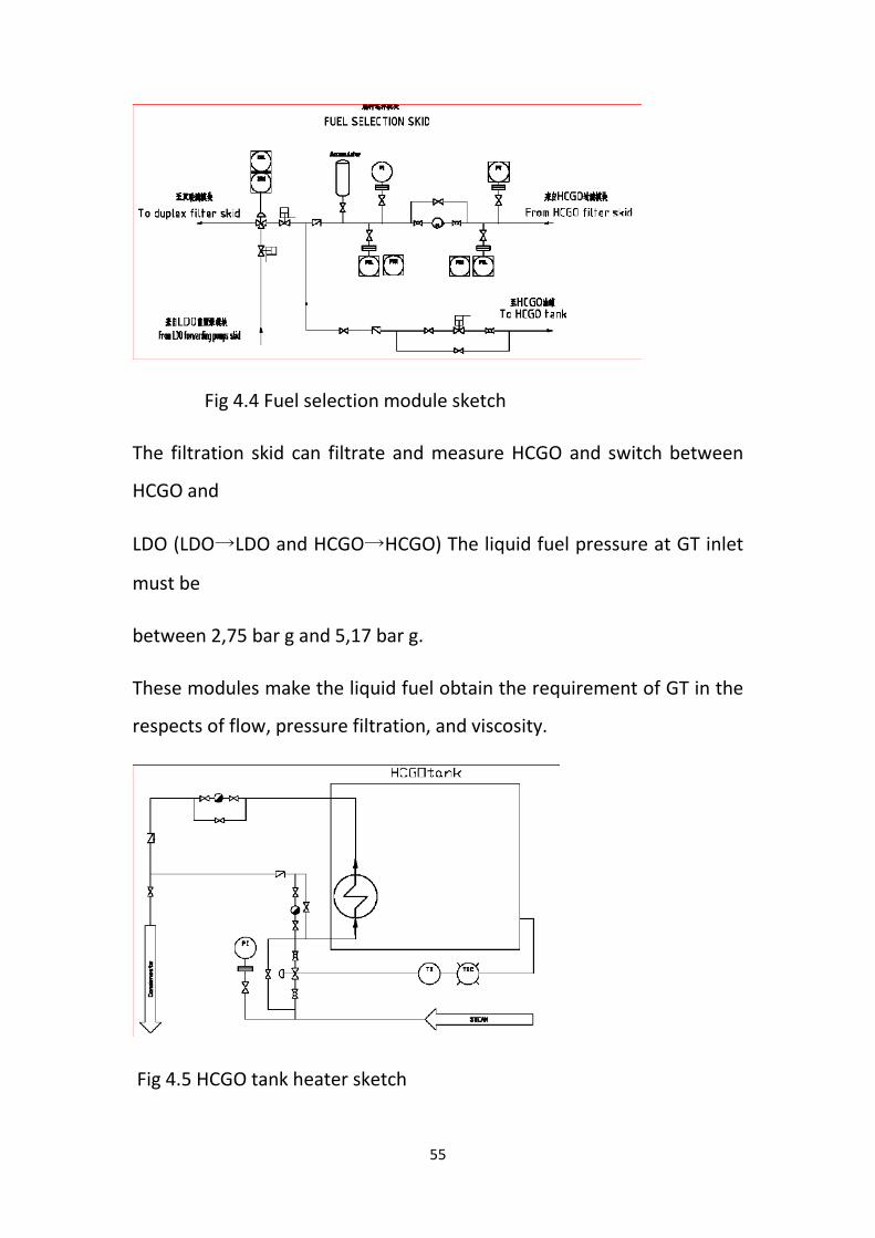
F. FUEL SELECTION MODULE
This skid controls fuel selection. When GT start up, fuel switch
valve is on LDO
position. As the load of GT rises to the switch load, the switch valve
slowly change to
HCGO position (if choose HCGO mode in MARK V). After about 10
minutes, the
switch valve is totally on HCGO position. When GT shuts down and loads
reduction to
the switch load or HCGO fuel faults, the switch valve quickly changes to
LDO position.
When GT trip with HCGO, the two pneumatic stop valves close
immediately, switch
valve changes to LDO position. In the following purge program,
pneumatic stop valve
of LDO piping will open to cooperate with HCGO purge valve VP1
complete purge
program.
55
Fig 4.4 Fuel selection module sketch
The filtration skid can filtrate and measure HCGO and switch between
HCGO and
LDO (LDO→LDO and HCGO→HCGO) The liquid fuel pressure at GT inlet
must be
between 2,75 bar g and 5,17 bar g.
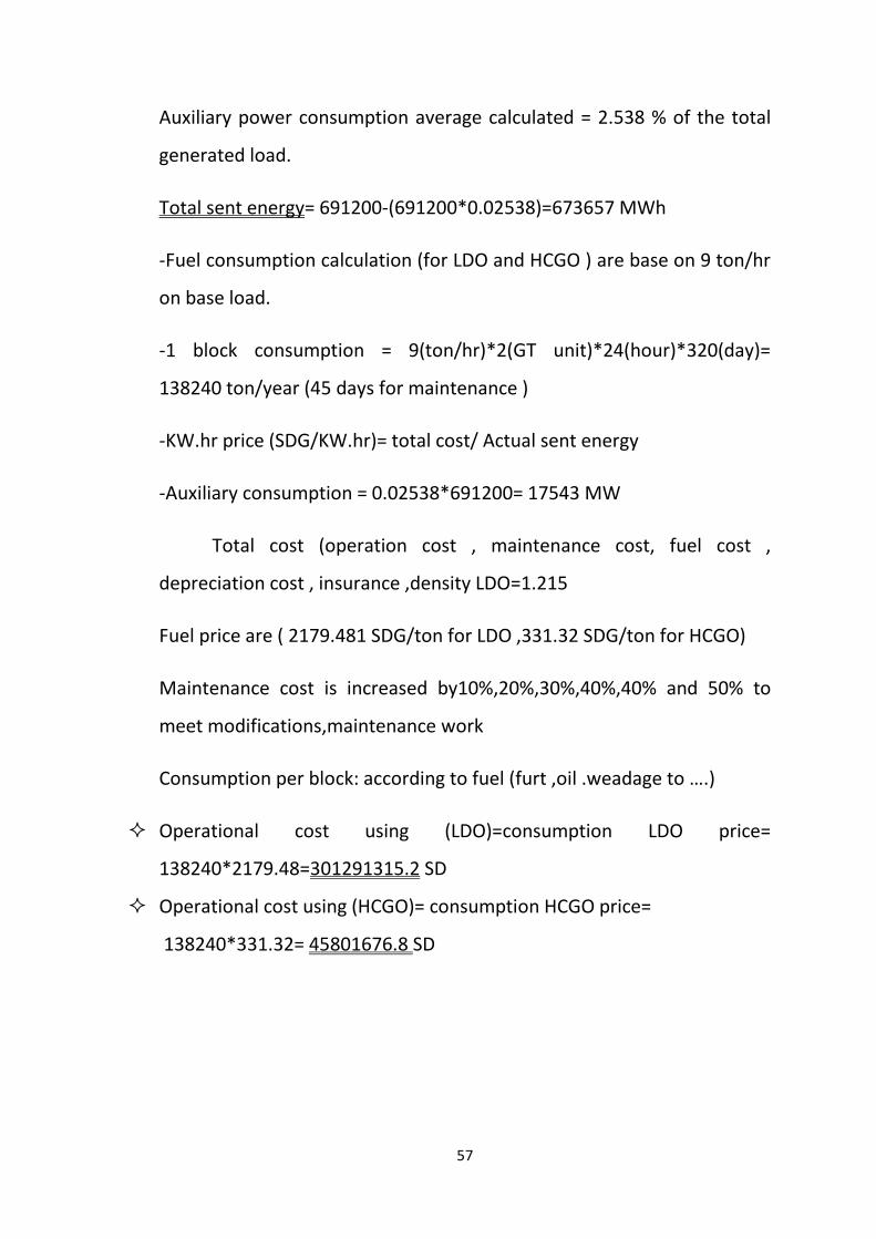
These modules make the liquid fuel obtain the requirement of GT in the
respects of flow, pressure filtration, and viscosity.
Fig 4.5 HCGO tank heater sketch

56
4.3 Calculation:-
All data collected from the garri1,2 power station, department
off efficiency and planning, monthly reports.
-fuel comparison is between (LDO, HCGO).
-Averages are taken for one block by dividing by 4.
- Estimated base load for each block 90 MW(each block consists of 2GT
unit and 1 ST unit)
-a load calculation is a base on 24 hours a day 320 for 1 year (subtract 45
days for maintenance work)
- 1 Block =30 MW * 3 unit * 24 hours * 320 days =691200MW output
57
Auxiliary power consumption average calculated = 2.538 % of the total
generated load.
Total sent energy= 691200-(691200*0.02538)=673657 MWh
-Fuel consumption calculation (for LDO and HCGO ) are base on 9 ton/hr
on base load.
-1 block consumption = 9(ton/hr)*2(GT unit)*24(hour)*320(day)=
138240 ton/year (45 days for maintenance )
-KW.hr price (SDG/KW.hr)= total cost/ Actual sent energy
-Auxiliary consumption = 0.02538*691200= 17543 MW
Total cost (operation cost , maintenance cost, fuel cost ,
depreciation cost , insurance ,density LDO=1.215
Fuel price are ( 2179.481 SDG/ton for LDO ,331.32 SDG/ton for HCGO)
Maintenance cost is increased by10%,20%,30%,40%,40% and 50% to
meet modifications,maintenance work
Consumption per block: according to fuel (furt ,oil .weadage to ….)
Operational cost using (LDO)=consumption LDO price=
138240*2179.48=301291315.2 SD
Operational cost using (HCGO)= consumption HCGO price=
138240*331.32= 45801676.8 SD
58
Operational cost saving between (LDO) and (HCGO) = 301291315.2 -
45801676.8 = 255489638.4 SDG/year
Kw.h price according to fuel=cost of fuel*consumption fuel / total sent
energy
For :
1- LDO
Kw.h price=301291315.2 / (673657 *10^3) = 0.44725 SD/kw.hr
2- HCGO
Kw.h price= 45801676.8 / (673657 *10^3) =0 .067989 SD/kw.hr
- Efficiency ƞ= total output / input
For LDO per block
ƞLDO=
- Heat rate
= 90*3600/(45500*18)= 0.395≈0.40
LDO
For HCGO per block
=1/ƞ = (1/0.40)*3600= 9000 KJ/kw.h
ƞHCGO=
-- Heat rate
= 90*3600/(44000*18)= 0.4090≈0.41
HCGO
=1/ƞ = (1/0.41)*3600= 8780.484 KJ/kw.h
59
4.4 Use Ansys program to analyses:-
Advanced GE materials are paving the way for dramatic
improvements in gas turbines —improvements that are setting new
records in giving customers the most fuel-efficient power generation
systems available. Combined-cycle efficiencies as high as 60% are now
achievable
because of increased firing temperature coupled with more efficient
component and system designs. Ongoing GE developments now
promise that the coming decade will witness continued growth of gas
turbines with higher firing temperatures, pressures, and outputs.
This paper describes the evolution of solutions to what used to be
incompatible market demands: high firing temperatures and long
life, corrosion protection from contaminated fuels and air, and higher
efficiency with fuel flexibility. It concentrates on advances made in
the hot gas path components because they are generally the most critical
part of the gas turbine. Improvements in superalloys and processing
now permit the hot gas path components to operate in advanced gas
turbines firing at increased temperatures for many thousands
of hours under severe conditions of centrifugal, thermal and vibratory
stresses. Recent improvements to compressors and rotors are
also discussed. GE engineers continue to lead the way in understanding
and developing materials technology for gas turbines because they can
tap knowledge from the laboratories of one of the world’s most

60
diversified companies, with products ranging from aircraft engines to
high technology plastics. They have used these resources and data
collected from more than 5,000 gas turbines operating in many climates,
and on a wide range of fuels, to verify that the materials will perform
under demanding conditions.[ 9]
61
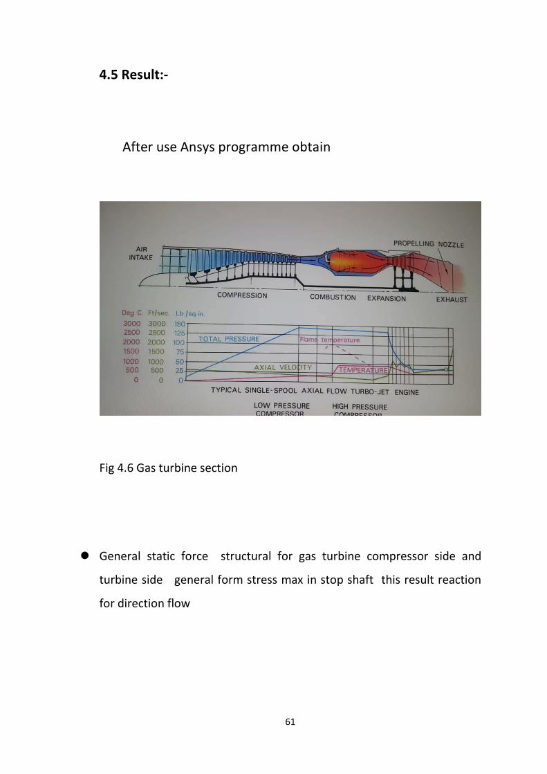
4.5 Result:-
After use Ansys programme obtain
Fig 4.6 Gas turbine section
General static force structural for gas turbine compressor side and
turbine side general form stress max in stop shaft this result reaction
for direction flow
62
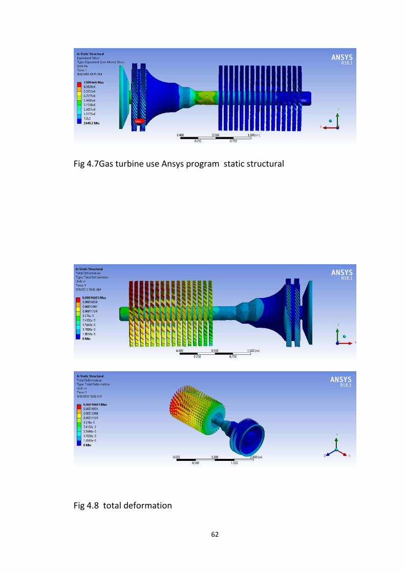
Fig 4.7Gas turbine use Ansys program static structural
Fig 4.8 total deformation
63
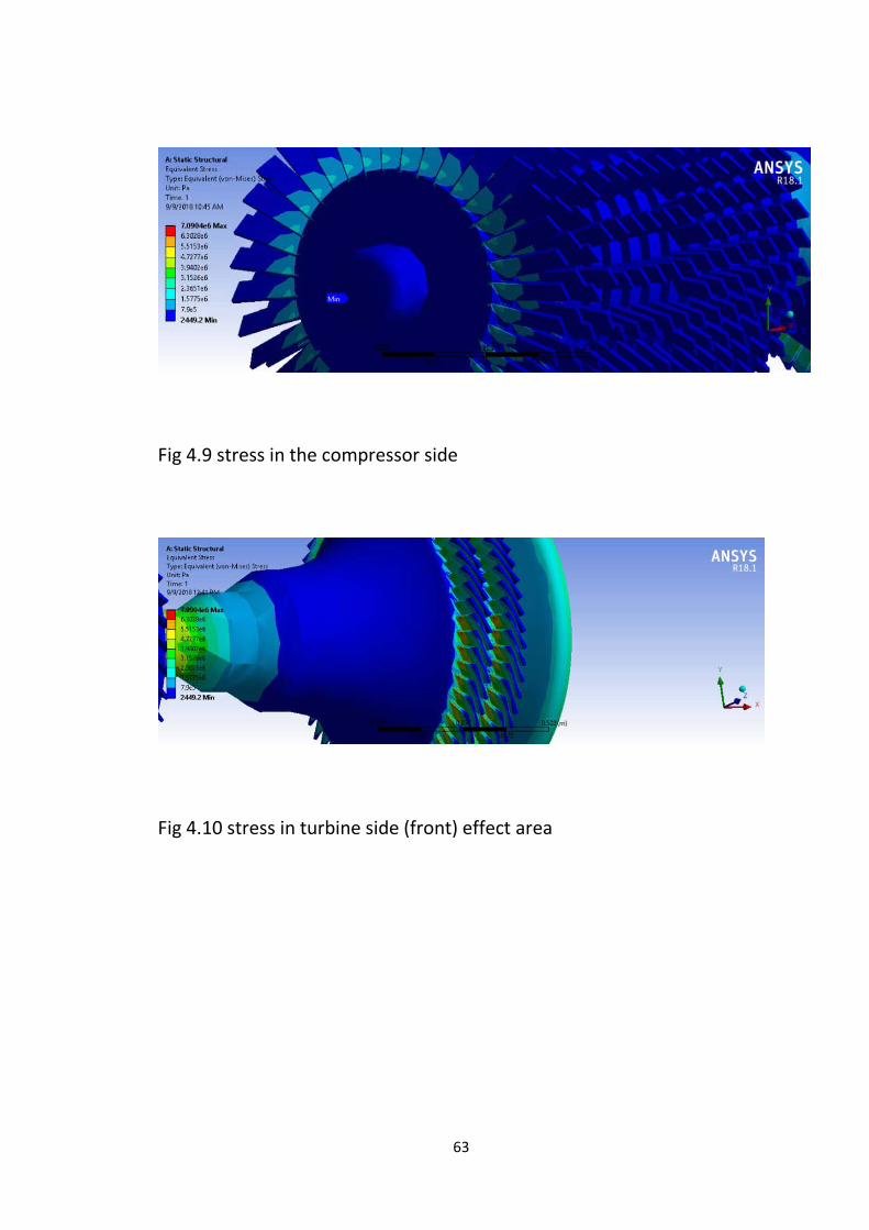
Fig 4.9 stress in the compressor side
Fig 4.10 stress in turbine side (front) effect area
64
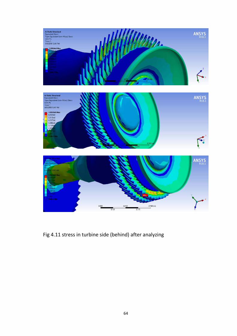
Fig 4.11 stress in turbine side (behind) after analyzing
65
Comment:=
General static force structural for gas turbine compressor side and
turbine side general form stress max in stop shaft this result reaction for
direction flow. (fig 4.4&4.5).
Form figure ( 4.5 &4.6 ) side effect on bucket we can see clearly and this
effect same actual inside maximum stress and heating, this heat
different for fuel to each other according to radiation and caloric value,
density, and specification of fuel.
4.6 Actually inside after use HCGO fuel:-
Fig 4.12 first stage bucket blade and tip actually effect.
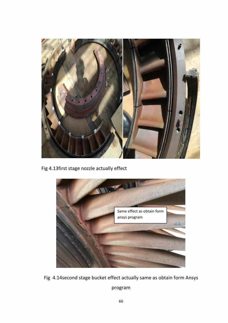
66
Fig 4.13first stage nozzle actually effect
Fig 4.14second stage bucket effect actually same as obtain form Ansys
program
Same effect as obtain form ansys program

67
Fig 4.15 third stage bucket actually effect on the profile
Fig 4.16 gas turbine section three stage
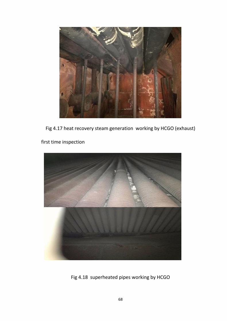
68
Fig 4.17 heat recovery steam generation working by HCGO (exhaust)
first time inspection
Fig 4.18 superheated pipes working by HCGO
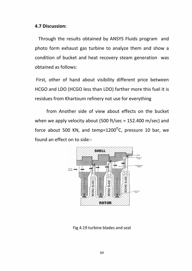
69
4.7 Discussion:
Through the results obtained by ANSYS Fluids program and
photo form exhaust gas turbine to analyze them and show a
condition of bucket and heat recovery steam generation was
obtained as follows:
First, other of hand about visibility different price between
HCGO and LDO (HCGO less than LDO) farther more this fuel it is
residues from Khartoum refinery not use for everything
from Another side of view about effects on the bucket
when we apply velocity about (500 ft/sec = 152.400 m/sec) and
force about 500 KN, and temp=1200O
C, pressure 10 bar, we
found an effect on to side:-
Fig 4.19 turbine blades and seal
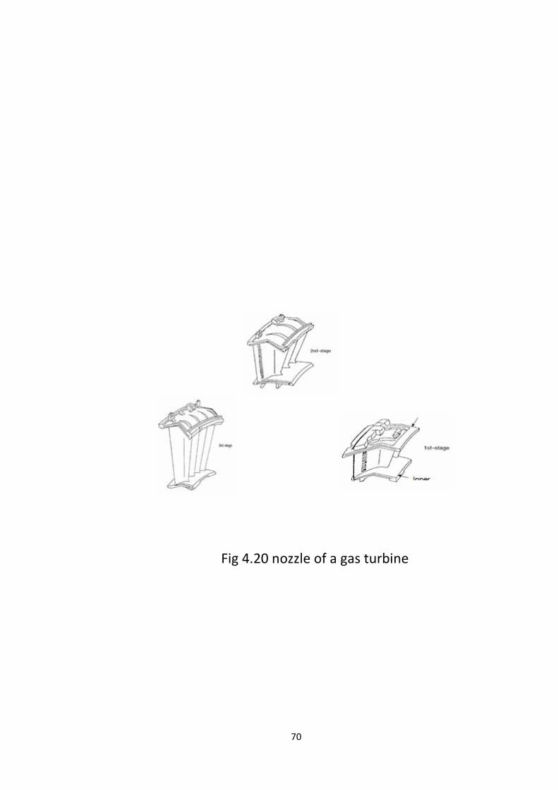
70
Fig 4.20 nozzle of a gas turbine
71
Firstly on the profile of bucket and nozzle tip and root of
the bucket on the suction side.
Note:- *(About bucket needs more or advance inspection we
can do outside of Sudan in special workshop use advance
inspector machine to the final report.)
And also expected the effect on liner according to high
radiation for fuel and temperature, because this fuel it distilled
fuel or last phase form refinery, and it contains residues and
impurities.
According to specification of fuel (HCGO) in chapter
four about viscosity (viscosity @40o
Other of hand we found more ash and co
c = 14.6 from target 17.14)
when use it , the part use Flow divider( distribute fuel equally
form combustion chamber ) need flashing by (L.D.O) to prevent
stuck with gear (when shutdown suddenly or trip) make it
works not properly, may be effective on spread temperature in
exhaust of gas turbine causes trip gas turbine.
2
in HRSG
should be effective in heat transfer on HRSG.we can do soot
blower to avoid ash form pipe every shutdown can start.
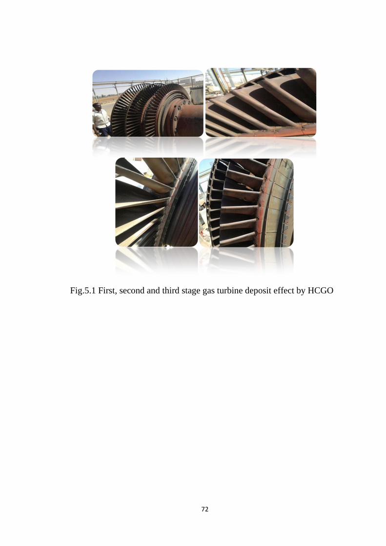
72
Fig.5.1 First, second and third stage gas turbine deposit effect by HCGO

73
Chapter 5

74
5.1 Conclusion:
Use new fuel (HCGO) in garri power station we can get
the highest benefit because it decreases the operational cost by about
78 % when compared with the base case.
The feasibility is high scored due to the kW.hr price which decreases
from 0.44725 SDG to 0.067989 SDG.
Other of hand use new fuel that implies availability LDO use vehicle
and industrial.
Better to use new technology in the bucket and nozzle of the turbine
about quoting and advance material.
Use soot blower in heat recovery steam generation (HRSG) to avoid
co2
Same effective results area inside turbine obtain after use any
programme(need more check-in the external workshop)
accumulated around the pipe at HRSG.
The weak point in this option is in the risks, especially in the
continuity of fuel oil from KRC.

75
5.2 Recommendation:
Gas turbine water wash is carried out to remove the deposit from
HCGO when the unit is cold and needs to operate water wash valves by
hands like compressor water wash.
It has to add new turbine water washing motor valve and new
piping. The new piping connects to original water washing skid.
- And also duration normal operation when we change filter and
replacement... don’t fill again let up to need to use it.
- Soot blower need to be installed to remove the ash form heat recovery
steam generation
- Select new spare part upgrade material and quoting bucket and
combustion chamber.
- Biro scope inspection time to time to check inside the turbine.
- Make a system to return water to the system again after heating HCGO
To reduce losses
76
Reference:
[1] Fuel Gases for Combustion in Heavy-Dig Gas Turbines G.E. 41040F Revised January
1999
[2] Garri power station
[3] IGCC Gas Turbines for Refinery Applications Robert M. Jones
Norman Z. Shilling GE Power Systems Schenectady, NY 12345
[4] Gas turbine fuel evaluation process: A case study on the application of
Arabian Super Light Crude Oil for use in GE 7F-class Dry Low Nox
[5] Fuel-flexible, efficient generation using internal combustion engines
(ICEs) to meet growing demand in Myanmar POWERGEN ASIA 2015
M. Raja go palan, Market Development Director, Middle East, Asia &
Australia Power Plants, Watseka India Pvt. Ltd. Stuti Gandotra, Market
Development Analyst, Middle East, Asia & Australia Power Plants,
Wärtsilä India Pvt. Lt.
(DLN) combustion systems.
[6] FUELS FLEXIBILITY IN HEAVY-DUTYGAS TURBINES
A.D. Foster, H.E. von Doe ring, and M.B. Hilt
GE Company Schenectady, New York
[7] Addressing Gas Turbine Fuel Flexibility ,GER4601 (06/09)
[8] Document at garri power station
Related Documents