1 Distance Vector Link State Hybrid Distance Vector vs. Link State Route table Topology Incremental Update Periodic Update Routing by rumor A B C D X E

Welcome message from author
This document is posted to help you gain knowledge. Please leave a comment to let me know what you think about it! Share it to your friends and learn new things together.
Transcript

1
Distance Vector
Link State
Hybrid
Distance Vector vs. Link State
Route table
TopologyIncremental Update
Periodic UpdateRouting by rumor
A B C D
X
E

2
Distance Vector vs. Link State
Distance Vector
• Updates frequently
• Each router is "aware" only of its immediate neighbors
• Slow convergence
• Prone to routing loops
• Easy to configure
Link State
• Updates are event triggered
• Each router is "aware" of all other routers in the "area"
• Fast convergence
• Less subject to routing loops
• More difficult to configure

3
Comparison Continued
Distance Vector
• Fewer router resources
required
• Updates require more
bandwidth
• Does not "understand"
the topology of the
network
Link State
• More router resource
intensive
• Updates require less
bandwidth
• Has detailed knowledge
of distant networks and
routers

5
Link State
Example
OSPF
IS-IS
OSPF is used for corporate networks
IS-IS is used for ISP’s

6

7
Open Shortest Path First (OSPF)
OSPF is an open standards routing protocol
This works by using the Dijkstra algorithm
OSPF provides the following features:
Minimizes routing update traffic
Allows scalability (e.g. RIP is limited to 15 hops)
Has unlimited hop count
Supports VLSM/CIDR
Allows multi-vendor deployment (open standard)

8
Link State
There are two types of Packets
Hello
LSA’s

9
OSPF Hello
• When router A starts it send Hello packet – uses 224.0.0.5
• Hello packets are received by all neighbors
• B will write A’s name in its neighbor table
• C also process the same way
A
B C
10
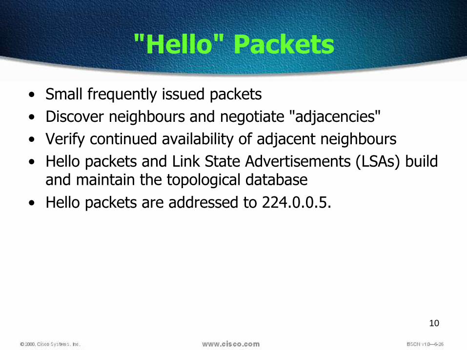
"Hello" Packets
• Small frequently issued packets
• Discover neighbours and negotiate "adjacencies"
• Verify continued availability of adjacent neighbours
• Hello packets and Link State Advertisements (LSAs) build and maintain the topological database
• Hello packets are addressed to 224.0.0.5.

11
Link State Advertisement(LSA)
An OSPF data packet containing link state and routinginformation that is shared among OSPF routers
LSAs are shared only with routers with whom it hasformed adjacencies
LSA packets are used to update and maintain thetopology database.

12
Link State
There are three type of tables
Neighbor
Topology
Routing

13
Tables
Neighbor
Contain information about the neighbors
Neighbor is a router which shares a link on samenetwork
Another relationship is adjacency
Not necessarily all neighbors
LSA updates are only when adjacency is established

14
Tables
Topology
Contain information about all network and path toreach any network
All LSA’s are entered in to topology table
When topology changes LSA’s are generated and sendnew LSA’s
On topology table an algorithm is run to create ashortest path, this algorithm is known as SPF ordijkstra algorithm

15
Tables
Routing Table
Also knows as forwarding database
Generated when an algorithm is run on the topologydatabase
Routing table for each router is unique
16
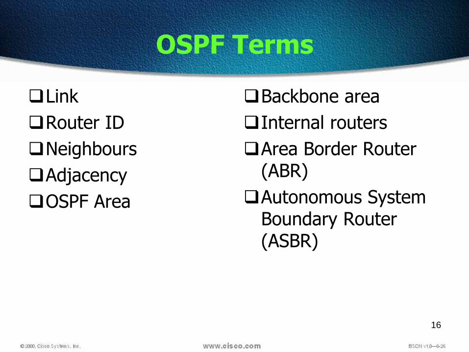
OSPF Terms
Link
Router ID
Neighbours
Adjacency
OSPF Area
Backbone area
Internal routers
Area Border Router (ABR)
Autonomous System Boundary Router (ASBR)

17
Link
A network or router interface assigned to agiven network
Link (interface) will have "state" informationassociated with it
Status (up or down)
IP Address
Network type (e.g. Fast Ethernet)
Bandwidth
Addresses of other routers attached to thisinterface

18
OSPF Term: Link
A link is a network or router interface assigned to any givennetworkThis link, or interface, will have state information associatedwith it (up or down) as well as one or more IP addresses

19
OSPF Term: Link State
Status of a link between two routersInformation is shared between directly connected routers.This information propagates throughout the network unchanged andis also used to create a shortest path first (SPF) tree.

20
Router ID
The Router ID (RID) is an IP address used to identify the router
Cisco chooses the Router ID by using the highest IP address of allconfigured loopback interfaces
If no loopback interfaces are configured with addresses, OSPF willchoose the highest IP address of all active physical interfaces.
You can manually assign the router ID.
The RID interface MUST always be up, therefore loopbacks arepreferred

21
Neighbours
Neighbours are two or more routers thathave an interface on a common network
E.g. two routers connected on a serial link
E.g. several routers connected on a commonEthernet or Frame relay network
Communication takes place between /among neighbours
neighbours form "adjacencies"

22
Adjacency
A relationship between two routers thatpermits the direct exchange of routeupdates
Not all neighbours will form adjacencies
This is done for reasons of efficiency – morelater
23
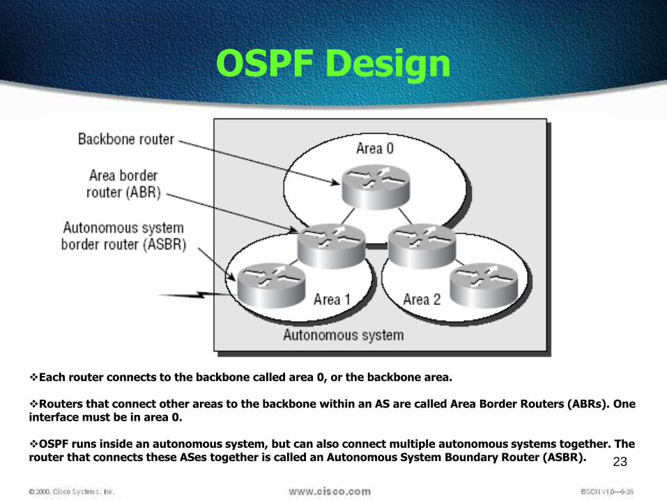
OSPF Design
Each router connects to the backbone called area 0, or the backbone area.
Routers that connect other areas to the backbone within an AS are called Area Border Routers (ABRs). One interface must be in area 0.
OSPF runs inside an autonomous system, but can also connect multiple autonomous systems together. The router that connects these ASes together is called an Autonomous System Boundary Router (ASBR).

24
OSPF Areas
An OSPF area is a grouping of contiguous networks androuters
Share a common area ID
A router can be a member of more than one area (areaborder router)
All routers in the same area have the same topologydatabase
When multiple areas exist, there must always be an area0 (the backbone) to which other areas connect

25
Why areas?
Decreases routing overhead
Compare to multiple smaller broadcast domainsinstead of one large one
Speeds convergence
Confines network instability (e.g. route "flapping") tosingle area of the network
Adds considerably to the complexity of setting up OSPF
CCNA certification deals only with single-area OSPF

26
Area Terminology
27
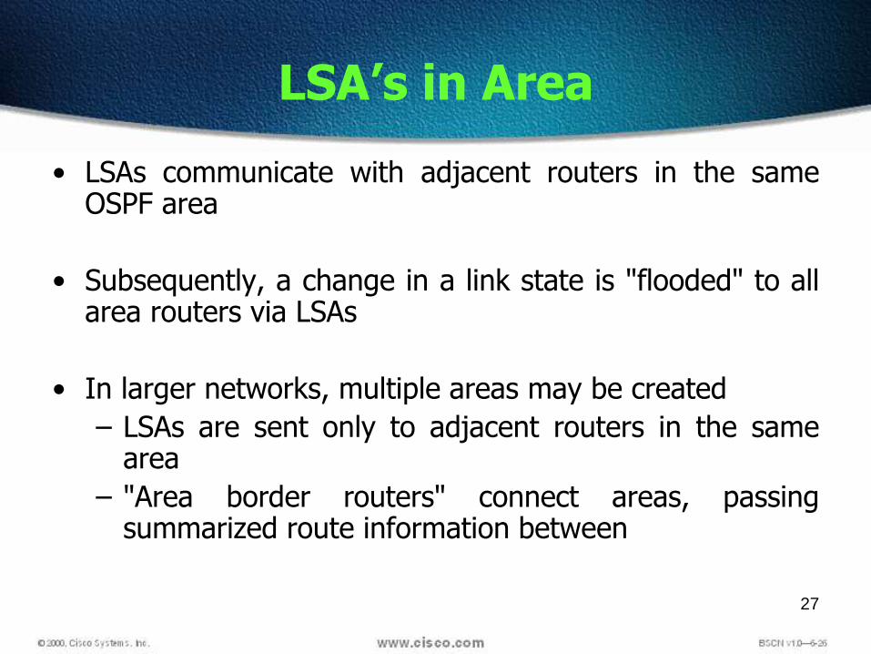
LSA’s in Area
• LSAs communicate with adjacent routers in the sameOSPF area
• Subsequently, a change in a link state is "flooded" to allarea routers via LSAs
• In larger networks, multiple areas may be created
– LSAs are sent only to adjacent routers in the samearea
– "Area border routers" connect areas, passingsummarized route information between

28
Path Calculation
Changes to the topological database of a router trigger arecalculation to re-establish the best route(s) to knownnetworks
Uses the SPF (shortest path first) algorithm developedby a computer scientist named Dijkstra
This is done by each individual router using itsdetailed "knowledge" of the whole network
Leads to rapid and accurate convergence
Based on detailed knowledge of every link in the areaand the OSPF "cost" of each
builds an OSPF tree with itself at the route
29
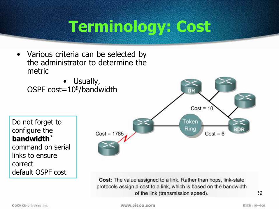
Terminology: Cost
• Various criteria can be selected bythe administrator to determine themetric
• Usually,OSPF cost=108/bandwidth
Do not forget toconfigure thebandwidth`command on serial links to ensure correctdefault OSPF cost
30
Pros and Cons
Note that OSPF is a more sophisticated routing protocol
Converges rapidly and accurately
Can use a metric calculation that effectively selectsthe "best" route(s) primarily based on bandwidth,although an OSPF cost can be administrativelyassigned
Use of OSPF requires
More powerful routing hardware
More detailed knowledge by the administrator,especially when large multi-area networks are used

31
Types of Neighbors
• OSPF can be defined for three type of neighbors
– Broadcast Multi Access (BMA) ex- Ethernet
– Point to Point
– Non-Broadcast Multi Access (NBMA)

32
OSPF Network Types

33
Adjacencies
Point to Point all routers form adjacencies
BMA & NBMA one router is elected as DR
DR establish adjacency with every neighbor router
LSA updates are exchanged only to DR
DR is the router which has highest priority
All CISCO routers has priority 1
If priority is same then router id is seen
The RID is highest IP address of all interfaces

34
Point-to-Point Links
Usually a serial interface running either PPPor HDLC
No DR or BDR election required
OSPF autodetects this interface type
OSPF packets are sent using multicast 224.0.0.5
All routers form adjacencies
35
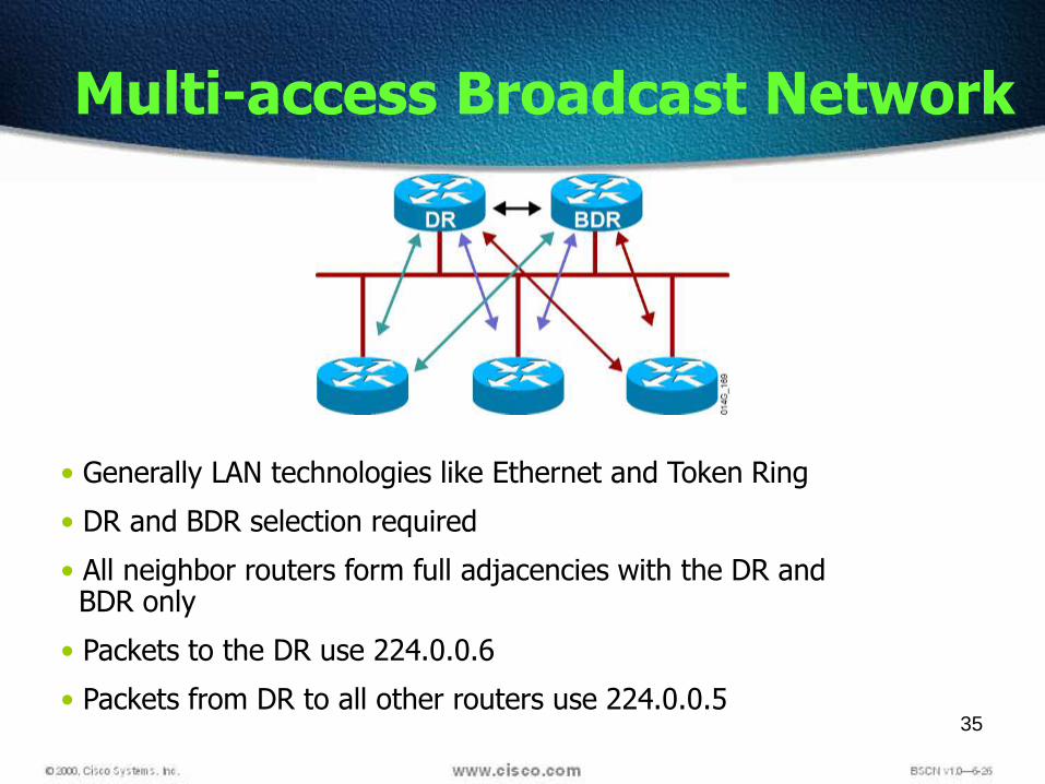
Multi-access Broadcast Network
• Generally LAN technologies like Ethernet and Token Ring
• DR and BDR selection required
• All neighbor routers form full adjacencies with the DR andBDR only
• Packets to the DR use 224.0.0.6
• Packets from DR to all other routers use 224.0.0.5

36
Electing the DR and BDR
Hello packets are exchanged via IP multicast.
The router with the highest priority isselected as the DR.
If Priority is same then Router ID is seen
Use the OSPF router ID as the tie breaker.

37
Terminology: DRs and BDRs
The designated router (DR) is responsible for generating LSAs on behalf of all routers connected to the same segment
38
DR Responsibility
When a router sees a new or changed link-state, it sendsan LSA to its DR using a particular multicast address
The DR then forwards the LSA to all the other routerswith whom it is adjacent
Minimizes the number of formal adjacencies thatmust be formed and therefore the amount of LSU(link state update) packet traffic in a multi-routernetwork

39
OSPF Summary
AD -100
Hop count is unlimited
Metric = Cost – 108/BW
Classless, VLSM
Load balance up to SIX routers
Require more processing power

40
Basic OSPF Configuration
Router(config)# router ospf 1
The number 1 in this example is a process-id # thatbegins an OSPF process in the routerMore than one process can be launched in a router,
but this is rarely necessaryUsually the same process-id is used throughout the
entire network, but this is not requiredThe process-id # can actually be any value from 1 to
"very large integer“The process-id # cannot be ZEROThis is NOT the same as the AS# used in IGRP and
EIGRP

41
Configuring OSPF Areas
After identifying the OSPF process, you need to identify the interfaces thatyou want to activate OSPF communications
Lab_A#config t
Lab_A(config)#router ospf 1
Lab_A(config-router)#network 10.0.0.0 0.255.255.255
area ?
<0-4294967295> OSPF area ID as a decimal value
A.B.C.D OSPF area ID in IP address format
Lab_A(config-router)#network 10.0.0.0 0.255.255.255
area 0
• Every OSPF network must have an area 0 (the backbone area) to which other areas connect So in a multiple area network, there must be an area 0 The wildcard mask represents the set of hosts supported by the
network and is really just the inverse of the subnet mask.

42
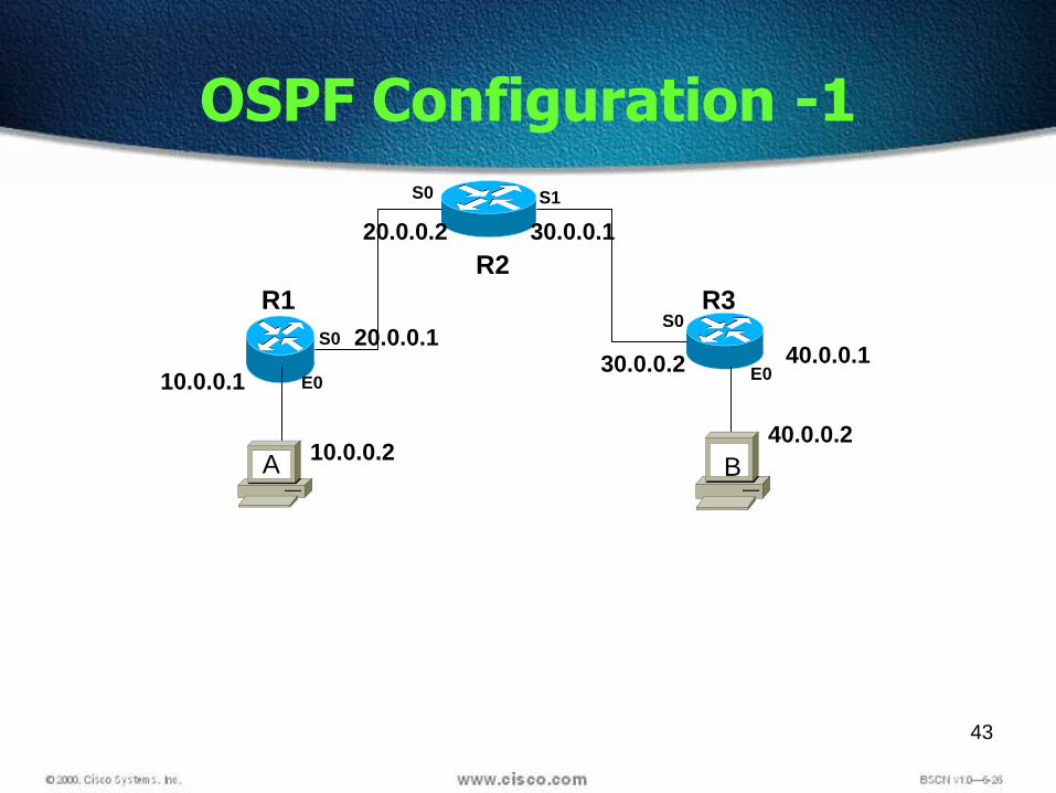
OSPF Configuration
• OSPF Process ID number is irrelevant. It can be the same on everyrouter on the network
• The arguments of the network command are the network number(10.0.0.0) and the wildcard mask (0.255.255.255)
• Wildcards - A 0 octet in the wildcard mask indicates that thecorresponding octet in the network must match exactly
• A 255 indicates that you don’t care what the corresponding octet isin the network number
• A network and wildcard mask combination of 1.1.1.1 0.0.0.0 wouldmatch 1.1.1.1 only, and nothing else.
• The network and wildcard mask combination of 1.1.0.0 0.0.255.255would match anything in the range 1.1.0.0–1.1.255.255
43
OSPF Configuration -1
R2
R1 R3
S0 S1
E0
S0
E0
S0
10.0.0.1
20.0.0.1
20.0.0.2 30.0.0.1
30.0.0.2 40.0.0.1
10.0.0.240.0.0.2
A B

44
OSPF Configuration -1
R2
R1 R3
S0 S1
E0
S0
E0
S0
10.0.0.1 20.0.0.1
20.0.0.2 30.0.0.1
30.0.0.2 40.0.0.1
10.0.0.240.0.0.2
R1#config tEnter configuration commands, one per line. End with CNTL/Z.R1(config)#router ospf 1R1(config-router)#network 10.0.0.0 0.255.255.255 area 0R1(config-router)#network 20.0.0.0 0.255.255.255 area 0R1(config-router)#^Z
A B

45
OSPF Configuration -2
R2
R1 R3
S0 S1
E0
S0
E0
S0
200.0.0.16/28
200.0.0.8/30200.0.0.12/30
200.0.0.32/27
A B

46
OSPF Configuration -2
R2
R1 R3
S0 S1
E0
S0
E0
S0
200.0.0.17
200.0.0.9
200.0.0.10 200.0.0.13
200.0.0.14 200.0.0.33
200.0.0.18 200.0.0.34255.255.255.240
255.255.255.252 255.255.255.252
255.255.255.224
A B

47
OSPF Configuration -2
R2
R1 R3
S0 S1
E0
S0
E0
S0
200.0.0.17
200.0.0.9
200.0.0.10 200.0.0.13
200.0.0.14 200.0.0.33
200.0.0.18 200.0.0.34255.255.255.240
255.255.255.252 255.255.255.252
255.255.255.224
R1#config tEnter configuration commands, one per line. End with CNTL/Z.R1(config)#router ospf 1R1(config-router)#network 200.0.0.16 0.0.0.15 area 0R1(config-router)#network 200.0.0. 8 0.0.0.3 area 0R1(config-router)#^Z
A B
R3#config tEnter configuration commands, one per line. End with CNTL/Z.R3(config)#router ospf 1R3(config-router)#network 200.0.0. 32 0.0.0.31 area 0R3(config-router)#network 200.0.0. 12 0.0.0.3 area 0R3(config-router)#^Z

48
OSPF and Loopback Interfaces
Configuring loopback interfaces when using the OSPF routingprotocol is important
Cisco suggests using them whenever you configure OSPF on arouter
Loopback interfaces are logical interfaces, which are virtual,software-only interfaces; they are not real router interfaces
Using loopback interfaces with your OSPF configuration ensures thatan interface is always active for OSPF processes.
The highest IP address on a router will become that router’s RID The RID is used to advertise the routes as well as elect the DR and
BDR. If you configure serial interface of your router with highest IP
Address this Address becomes RID of t is the RID of the routerbecause e router
If this interface goes down, then a re-election must occur It can have an big impact when the above link is flapping

49
Configuring Loopback Interfaces
R1#config t
Enter configuration commands, one per line. End with CNTL/Z.
R1(config)#int loopback 0
R1(config-if)#ip address 172.16.10.1 255.255.255.255
R1(config-if)#no shut
R1(config-if)#^Z
R1#

50
show ip protocols
Router#
• Verifies the configured IP routing protocol processes, parameters and statistics
Verifying OSPF Operation
show ip route ospf
Router#
• Displays all OSPF routes learned by the router
show ip ospf interface
Router#
• Displays the OSPF router ID, area ID and
adjacency information

51
show ip ospf
Router#
• Displays the OSPF router ID, timers, and statistics
Verifying OSPF Operation (Cont.)
show ip ospf neighbor [detail]
Router#
• Displays information about the OSPF neighbors,
including Designated Router (DR) and Backup
Designated Router (BDR) information on
broadcast networks

52
The show ip route ospf Command
RouterA# show ip route ospf
Codes: C - connected, S - static, I - IGRP, R - RIP, M - mobile,
B - BGP, D - EIGRP, EX - EIGRP external, O - OSPF,
IA - OSPF inter area, E1 - OSPF external type 1,
E2 - OSPF external type 2, E - EGP, i - IS-IS, L1 - IS-IS
level-1, L2 - IS-IS level-2, * - candidate default
Gateway of last resort is not set
10.0.0.0 255.255.255.0 is subnetted, 2 subnets
O 10.2.1.0 [110/10] via 10.64.0.2, 00:00:50, Ethernet0

53
The show ip ospf interface Command
RouterA# show ip ospf interface e0
Ethernet0 is up, line protocol is up
Internet Address 10.64.0.1/24, Area 0
Process ID 1, Router ID 10.64.0.1, Network Type BROADCAST, Cost: 10
Transmit Delay is 1 sec, State DROTHER, Priority 1
Designated Router (ID) 10.64.0.2, Interface address 10.64.0.2
Backup Designated router (ID) 10.64.0.1, Interface address 10.64.0.1
Timer intervals configured, Hello 10, Dead 40, Wait 40, Retransmit 5
Hello due in 00:00:04
Neighbor Count is 1, Adjacent neighbor count is 1
Adjacent with neighbor 10.64.0.2 (Designated Router)
Suppress hello for 0 neighbor(s)

54
The show ip ospf neighbor Command
RouterB# show ip ospf neighbor
Neighbor ID Pri State Dead Time Address Interface
10.64.1.1 1 FULL/BDR 00:00:31 10.64.1.1 Ethernet0
10.2.1.1 1 FULL/- 00:00:38 10.2.1.1 Serial0

55
show ip ospf neighbor detail
show ip ospf database

56
Setting Priority for DR Election
ip ospf priority number
This interface configuration command assigns the OSPF priority to an interface.
Different interfaces on a router may be assigned different values.
The default priority is 1. The range is from 0 to 255.0 means the router is a DROTHER; it can’t be the DR or
BDR.
Router(config-if)#

57

58
EIGRP
• IGRP– DV– Easy to configure– Neighbor– Advanced Metric– Periodic– Broadcast
• OSPF
– LS
– Incremental Updates
– Multicast
– Open Standard
• EIGRP
– Hybrid
– DUAL
– Topology Database
– Rapid Convergence
– Reliable

59
Overview
Enhanced Interior Gateway Routing Protocol (EIGRP) is a Cisco-proprietary routing protocol based on Interior Gateway Routing Protocol(IGRP).
Released in 1994, Unlike IGRP, which is a classful routing protocol,EIGRP supports CIDR and VLSM.
it is probably one of the two most popular routing protocols in usetoday.
Compared to IGRP, EIGRP boasts faster convergence times, improvedscalability, and superior handling of routing loops.
EIGRP is often described as a hybrid routing protocol, offering thebest of distance vector and link-state algorithms.

60
Comparing EIGRP with IGRP
IGRP and EIGRP are compatible with each other.EIGRP offers multiprotocol support, but IGRP does not.Communication via Reliable Transport Protocol (RTP)Best path selection via Diffusing Update Algorithm (DUAL)Improved convergence timeReduced network overhead
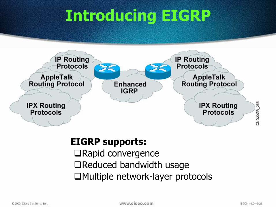
Introducing EIGRP
EIGRP supports:
Rapid convergence
Reduced bandwidth usage
Multiple network-layer protocols
62
EIGRP Tables
• EIGRP maintains 3 tables
– Neighbor table
– Topology table
– Routing table

63
Neighbor Discovery
There are three conditions that must be
met for neighborship establishment
Hello or ACK received
AS numbers match
Identical metrics (K values)
? AS
? K
K1 – BWK2- DelayK3-LoadK3-ReliabilityK5-MTU
64
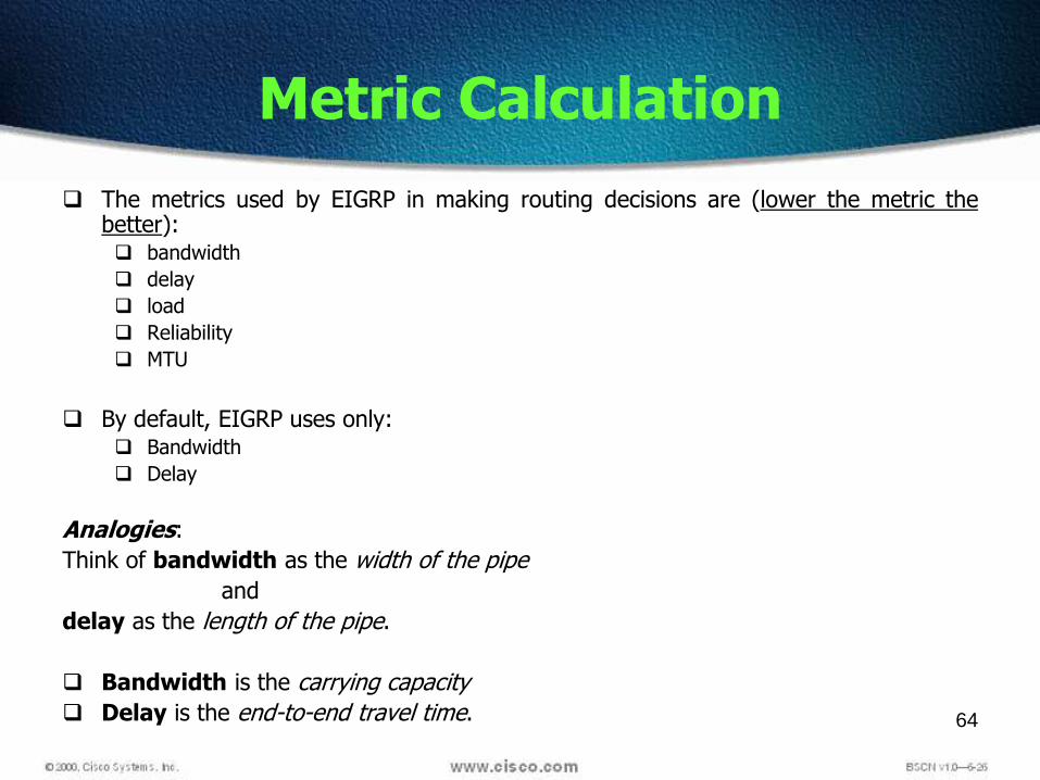
The metrics used by EIGRP in making routing decisions are (lower the metric thebetter): bandwidth
delay
load
Reliability
MTU
By default, EIGRP uses only: Bandwidth
Delay
Analogies:
Think of bandwidth as the width of the pipe
and
delay as the length of the pipe.
Bandwidth is the carrying capacity
Delay is the end-to-end travel time.
Metric Calculation

65
Neighbor Table
The neighbor table is the most important table in EIGRP
Stores address and interface of neighbor
66
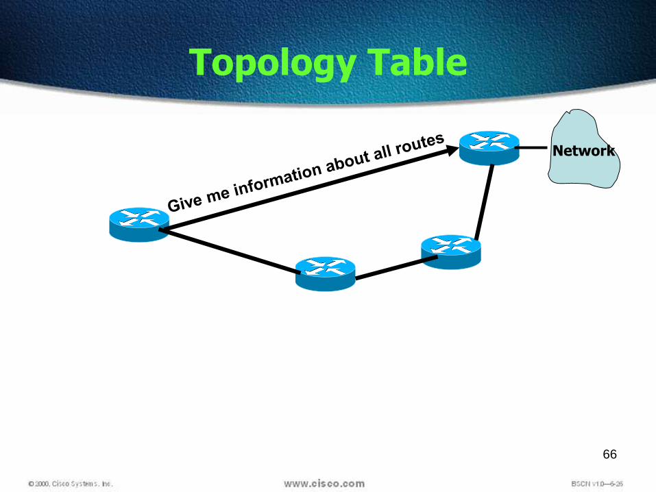
Topology Table
Network

67
Topology Table
The topology table is made up of all the EIGRP routing tables in theautonomous system.
DUAL takes the information and calculates the lowest cost routes to eachdestination.
By tracking this information, EIGRP routers can identify and switch toalternate routes quickly.
The information that the router learns from the DUAL is used to determinethe successor route, which is the term used to identify the primary or bestroute.
Every EIGRP router maintains a topology table. All learned routes to adestination are maintained in the topology table.
68
Routing Tables
A successor is a route selected as the primary route touse to reach a destination.
DUAL calculates Successor (Primary Route) and places itin the routing table (and topology table)
Can have up to 4 successors of equal or unequal value DUAL calculates Feasible Successor (Backup Route) and
places it in the Topology Table. Promoted to successor if the route goes down if it has a
lower cost than current successor If no FS in Table - Send query Multiple feasible successors for a destination can be
retained in the topology table although it is notmandatory
69
EIGRP Concepts & Terminology
EIGRP routers that belong to different autonomoussystems (ASes) don’t automatically share routinginformation
The only time EIGRP advertises its entire routing table iswhen it discovers a new neighbor and forms anadjacency with it through the exchange of Hello packets
When this happens, both neighbors advertise their entirerouting tables to one another
After each has learned its neighbor’s routes, onlychanges to the routing table are propagated

70
172.16.100.0
1.544Mbps
56Kbps
1.544Mbps
Dist to 172.16.100.0 =100Dist to 172.16.100.0 =100
Dist to 172.16.100.0 =350
10Mbps
10Mbps – 1001,544Mbps – 25056Kbps -1000
Chennai receives an update from Mumbai with a cost of 100, which is Mumbai's cost to reach 172.16.100.0, Thiscost is referred to as the reported distance (RD)Bangalore will report its cost to reach 172.16.100.0. Bangalore's RD is 350Chennai will compute its cost to reach 172.16.100.0 via Mumbai and Bangalore and compare the metrics for thetwo pathsChennai's cost via Mumbai is 1100. Chennai's cost via Bangalore is 600. The lowest cost to reach a destination isreferred to as the feasible distance (FD) for that destinationChennai's FD to 172.16.100.0 is 600. The next-hop router in the lowest-cost path to the destination is referred toas the successor.A feasible successor is a path whose reported distance is less than the feasible distance, and it is considered abackup route.

71
EIGRP Terms
Feasible distance (FD) - This is the lowest calculated metric toreach destination. This is the route that you will find in therouting table, because it is considered the best path
Reported distance (RD) - The distance reported by anadjacent neighbor to a specific destination.
Interface information - The interface through which thedestination can be reached.
Route status - The status of a route. Routes are identified asbeing either passive, which means that the route is stable andready for use, or active, which means that the route is in theprocess of being recomputed by DUAL

72
Successor – Current Route
A successor is a route selected as the primary route to use to reacha destination.
Successors are the entries kept in the routing table.
Feasible Successor - A backup route
A feasible successor is a backup route.
These routes are selected at the same time the successors areidentified, but they are kept in the topology table.
Multiple feasible successors for a destination can be retained in thetopology table.
EIGRP Terminology and Operations

73
Reliable Transport Protocol (RTP)
Used by EIGRP for its routing updates in place of TCP EIGRP can call on RTP to provide reliable or unreliable service
EIGRP uses reliable service for route updates Unreliable for Hellos
Reliable Transport Protocol (RTP) is a transport layer protocol thatguarantees ordered delivery of EIGRP packets to all neighbors.
On an IP network, hosts use TCP to sequence packets and ensuretheir timely delivery. RIP uses UDP
However, EIGRP is protocol-independent and does not rely on TCP/IPto exchange routing information the way that RIP, IGRP, and OSPFdo.
EIGRP uses RTP as its own proprietary transport layer protocol toguarantee delivery of routing information.
With RTP, EIGRP can multicast and unicast to different peerssimultaneously.

74
Diffusing Update Algorithm (DUAL)
All route computations in EIGRP are handled by DUAL
One of DUAL's tasks is maintaining a table of loop-free paths toevery destination.
This table is referred to as the topology table
DUAL saves all paths in the topology table
The least-cost path(s) is copied from the topology table to therouting table
In the event of a failure, the topology table allows for very quickconvergence if another loop-free path is available
If a loop-free path is not found in the topology table, a routerecomputation must occur
DUAL queries its neighbors, who, in turn, may query theirneighbors, and so on...
Hence the name "Diffusing" Update Algorithm

75
VLSM Support
• EIGRP supports the use of Variable- Length SubnetMasks
• Can use 30-bit subnet masks for point-to-point networks
• Because the subnet mask is propagated with every routeupdate, EIGRP also supports the use of discontiguoussubnets
• Discontiguous network is the one that has two or moresubnetworks of a classful network connected together bydifferent classful networks

76
Discontiguous Network

Configuring EIGRP
Router(config-router)#network network-number
• Selects participating attached networks
Router(config)#router eigrp autonomous-system
• Defines EIGRP as the IP routing protocol

EIGRP Configuration Example
80
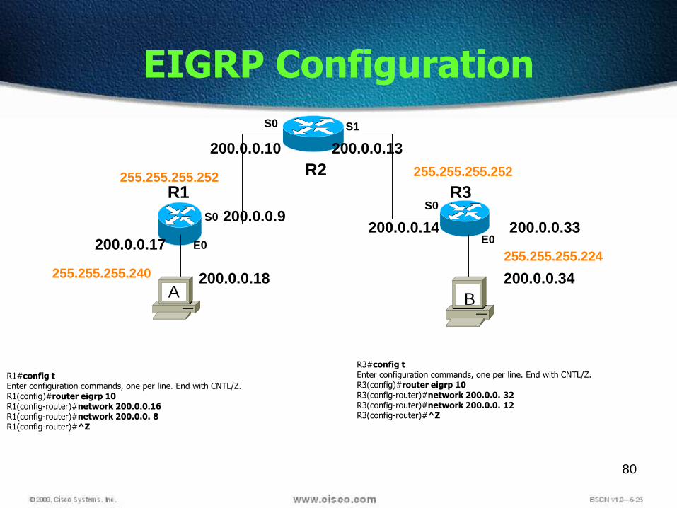
EIGRP Configuration
R2
R1 R3
S0 S1
E0
S0
E0
S0
200.0.0.17
200.0.0.9
200.0.0.10 200.0.0.13
200.0.0.14 200.0.0.33
200.0.0.18 200.0.0.34255.255.255.240
255.255.255.252 255.255.255.252
255.255.255.224
R1#config tEnter configuration commands, one per line. End with CNTL/Z.R1(config)#router eigrp 10R1(config-router)#network 200.0.0.16R1(config-router)#network 200.0.0. 8R1(config-router)#^Z
A B
R3#config tEnter configuration commands, one per line. End with CNTL/Z.R3(config)#router eigrp 10R3(config-router)#network 200.0.0. 32R3(config-router)#network 200.0.0. 12R3(config-router)#^Z

81
Verifying the EIGRP Configuration
To verify the EIGRP configuration a number of show
and debug commands are available.
These commands are shown on the next few slides.

82
show ip eigrp topology
show ip eigrp topology[active | pending | successors]

83
show ip eigrp topologyall-links
show ip eigrp traffic

84
Administrative Distances

85
TELNET
Getting information about remote device
Can connect to remote device and configure a device
Password must be set
R1(config)# line vty 0 4
Password cisco
login

86
© 2002, Cisco Systems, Inc. All rights reserved. 86
Discovering Neighbors on the Network

Cisco Discovery Protocol
CDP is a proprietary utility that gives you a summary of directlyconnected switches, routers, and other Cisco devices.
CDP discovers neighboring devices regardless of which protocolsuite they are running.
Runs on the Data link layer
Physical media must support the Subnetwork Access Protocol(SNAP) encapsulation.
Only give directly connected device
By default enabled, you can enable or disable

Discovering Neighbors with CDP
CDP runs on routers with Cisco IOS®
software Release 10.3 or later and on Cisco switches.
Show CDP ?
Summary information includes:
Device ID Local Interface Port ID Capabilities list Platform

89
CDP
CDP timer is how often CDP packets are transmitted to
all active interfaces.
Router(config)#cdp timer 90
CDP holdtime is the amount of time that the device willhold packets received from neighbor devices.
Router(config)#cdp holdtime 240

90
Using CDP
91
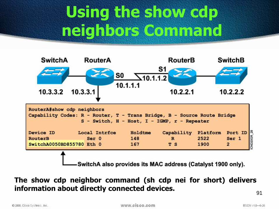
Using the show cdp neighbors Command
The show cdp neighbor command (sh cdp nei for short) deliversinformation about directly connected devices.

92
CDP
show cdp neighbor detail
This command can be run on both routers
and switches, and it displays detailed
information about each device connected
to the device

93
Using the show cdp entry Command
The show cdp entry * command displays the same information as the show cdpneighbor details command.

94
Additional CDP Commands
The show cdp traffic command displays information aboutinterface traffic, including the number of CDP packets sent andreceived and the errors with CDP.
95
CDP Commands
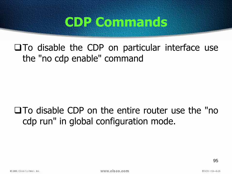
To disable the CDP on particular interface usethe "no cdp enable" command
To disable CDP on the entire router use the "nocdp run" in global configuration mode.

96
Summary
Cisco Discovery Protocol is an information-gathering tool usedby network administrators to get information about directlyconnected devices.
CDP exchanges hardware and software device informationwith its directly connected CDP neighbors.
You can enable or disable CDP on a router as a whole or on aport-by-port basis.
The show cdp neighbors command displays information abouta router’s CDP neighbors.
The show cdp entry, show cdp traffic, and show cdp interfacecommands display detailed CDP information on a Cisco device.

97

Manage IP traffic as network access grows
Filter packets as they pass through the router
Why Use Access Lists?

99
What are ACLs?
ACLs are lists of conditions that are applied to traffic traveling acrossa router's interface.
These lists tell the router what types of packets to accept or deny.
Acceptance and denial can be based on specified conditions.
ACLs can be configured at the router to control access to a networkor subnet.
Some ACL decision points are source and destination addresses,protocols, and upper-layer port numbers.

100
Reasons to Create ACLs
The following are some of the primary reasons to createACLs:
Limit network traffic and increase network performance.Provide traffic flow control.Provide a basic level of security for network access.Decide which types of traffic are forwarded or blocked at the routerinterfacesFor example: Permit e-mail traffic to be routed, but block all telnet traffic.If ACLs are not configured on the router, all packets passing through therouter will be allowed onto all parts of the network.

101
ACL’s
Different access list for Telnet
When configuring ISDN you need to use access list
Implicit deny at bottom
All restricted statements should be on first
There are two types
Standard
Extended

102
Network
N1 N2
N3 N4 N5 N6
192.168.12.0
A
B C
192.168.34.0192.168.56.0
192.168.12.2192.168.12.3
103
IP Packet
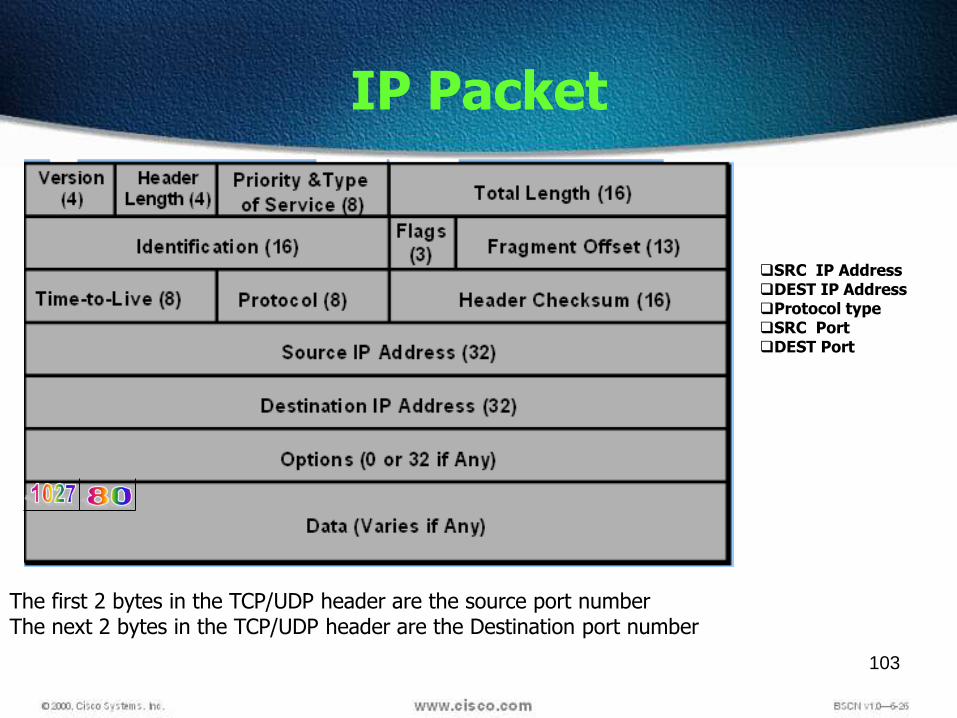
SRC IP AddressDEST IP AddressProtocol typeSRC PortDEST Port
The first 2 bytes in the TCP/UDP header are the source port numberThe next 2 bytes in the TCP/UDP header are the Destination port number

104
Standard
Checks source address
Permits or denies entire protocol suite
Extended
Checks source and destination address
Generally permits or denies specific protocols
Types of Access Lists

How to Identify Access Lists
Standard IP lists (1-99) test conditions of all IP packets fromsource addresses.
Extended IP lists (100-199) test conditions of source and destinationaddresses, specific TCP/IP protocols, and destination ports.
Standard IP lists (1300-1999) (expanded range).
Extended IP lists (2000-2699) (expanded range).

106
Standard ACLs
The full syntax of the standard ACL command is:
Router(config)#access-list access-list-number {deny | permit} source[source-wildcard ]
The no form of this command is used to remove a standard ACL. This isthe syntax:Router(config)#no access-list access-list-number
Config# Access-list 1 deny 192.168.1.0 0.0.0.255Config# access-list 1 permit any

107
Wildcard Mask
Access-list 99 permit 192.168.1.1 wildcard mask
All 32 bits of an IP Address can be filtered
Wildcard inverse mask
0=must match
1= ignore
MASK (192.168.1.1) Matching IP
0.0.0.0 (host) 192.168.1.1
0.0.0.255 192.168.1.0-255
0.0.255.255 192.168.0-255.0-255
0.255.255.255 192.0-255.0-255.0-255
255.255.255.255 0-255.0-255.0-255.0-255 (any)

108
The ANY and HOST keyword
Access-list 1 permit 200.0.0.9 0.0.0.0
Or
permit host 200.0.0.9
Access-list 1 permit 0.0.0.0 255.255.255.255
Or
permit any

Testing Packets with Standard Access Lists
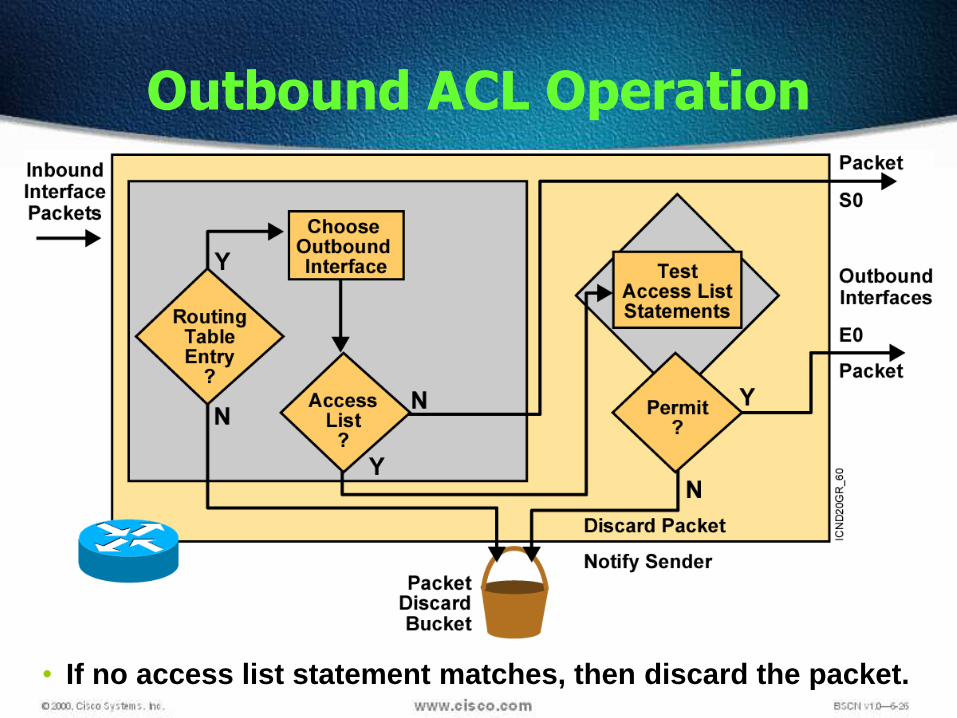
Outbound ACL Operation
• If no access list statement matches, then discard the packet.

111
Reading an ACL
First Hit or Best Fit?
1. Access-list 99 deny host 192.168.1.1 0.0.0.0
access-list 99 permit any 255.255.255.255
2. Access-list 99 permit 192.168.1.0 0.0.0.255
Access-list 99 deny host 192.168.1.1
access-list 99 permit any
3. Access-list 99 deny host 192.168.1.1
Implicit deny at the end of every ACL

112
Creating ACLs
ACLs are created in the global configuration mode. There are manydifferent types of ACLs including standard, extended, IPX, AppleTalk, andothers. When configuring ACLs on a router, each ACL must be uniquelyidentified by assigning a number to it. This number identifies the type ofaccess list created and must fall within the specific range of numbers thatis valid for that type of list.
Since IP is by far the mostpopular routed protocol,addition ACL numbers havebeen added to newer routerIOSs.Standard IP: 1300-1999Extended IP: 2000-2699

113
The ip access-group command
{ in | out }
114
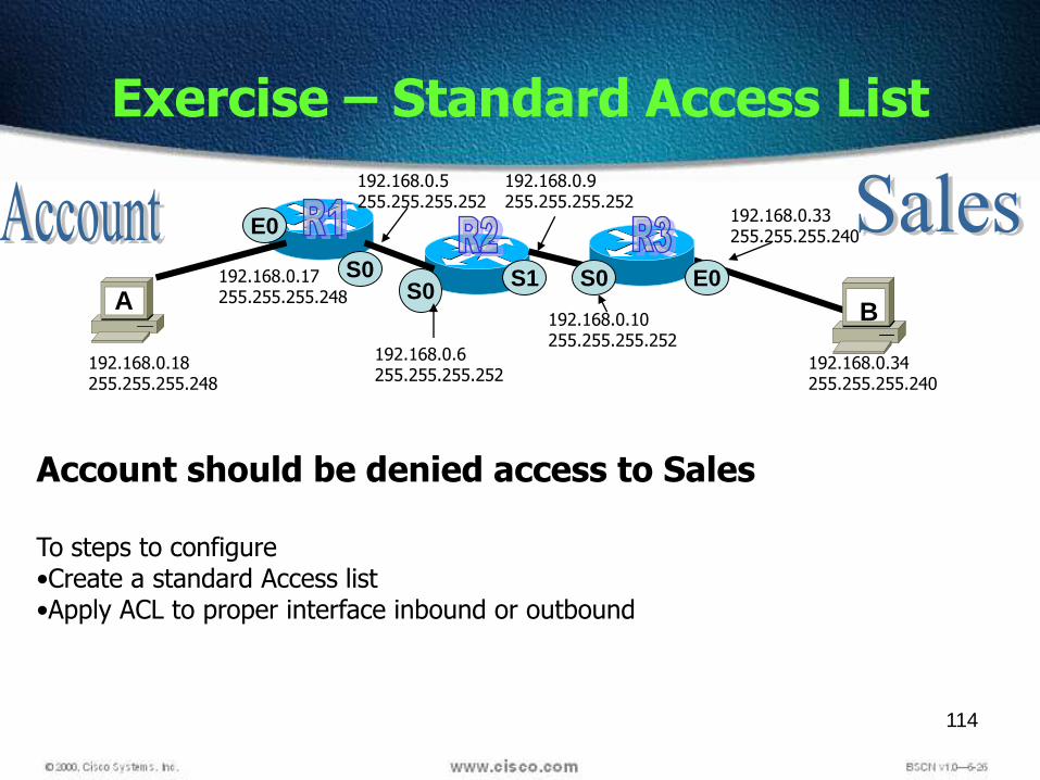
Exercise – Standard Access List
A B
Account should be denied access to Sales
To steps to configure•Create a standard Access list•Apply ACL to proper interface inbound or outbound
S0 S0
E0
E0
192.168.0.18255.255.255.248
S0S1192.168.0.17
255.255.255.248
192.168.0.5255.255.255.252
192.168.0.6255.255.255.252
192.168.0.9255.255.255.252
192.168.0.10255.255.255.252
192.168.0.33255.255.255.240
192.168.0.34255.255.255.240

115
Exercise – Standard Access List
A B
S0 S0
E0
E0
192.168.0.18255.255.255.248
S0S1192.168.0.17
255.255.255.248
192.168.0.5255.255.255.252
192.168.0.6255.255.255.252
192.168.0.9255.255.255.252
192.168.0.10255.255.255.252
192.168.0.33255.255.255.240
192.168.0.34255.255.255.240
Config# Access-list 1 deny 192.168.0.18 0.0.0.7Config# access-list 1 permit any
Config#int e 0Config-if# ip access-group 1 out

116
Extended ACLs
Extended ACLs are used more often than standard ACLs because they provide agreater range of control.
Extended ACLs check the source and destination packet addresses as well asbeing able to check for protocols and port numbers.
At the end of the extended ACL statement, additional precision is gained from afield that specifies the optional Transmission Control Protocol (TCP) or UserDatagram Protocol (UDP) port number.
Logical operations may be specified such as, equal (eq), not equal (neq), greaterthan (gt), and less than (lt), that the extended ACL will perform on specificprotocols.
Extended ACLs use an access-list-number in the range 100 to 199 (also from 2000to 2699 in recent IOS).

117
Configuration
• Access-list acl# {permit/Deny}• Protocol
• Src IP src WCM
• Dst IP dst WCM
• Opetrator port• Protocol
– OSPF
– EIGRP
– ICMP
– TCP
– UDP
RP If you need to Block a routing protocol
IP• Operator
– eq
– gt
– lt
– neq

Testing Packets with Extended Access Lists

119
Extended ACL Syntax

121
Extended ACL LAB -2
S0
S0
E0E0
A B
192.168.0.34 should be denied FTP of 192.168.0.18
On Router R1Config# Access-list 100 deny tcp 192.168.0.34 0.0.0.0 192.168.0.18
0.0.0.0 eq 21Config# access-list 100 permit IP any any
Config#int s0Config-if# ip access-group 100 IN
192.168.0.18 should be denied website of 192.168.0.34
On Router R3Config# Access-list 100 deny tcp 192.168. 0.18 0.0.0.0 192.168.0.34
0.0.0.0 eq 80Config# access-list 100 permit IP any any
Config#int s0Config-if# ip access-group 100 IN
S1S0
192.168.0.18255.255.255.248
192.168.0.17255.255.255.248
192.168.0.5255.255.255.252
192.168.0.6255.255.255.252
192.168.0.9255.255.255.252
192.168.0.10255.255.255.252
192.168.0.33255.255.255.240
192.168.0.34255.255.255.240

122
Deny FTP
access-list 101 deny tcp any any eq 21
access-list 101 permit ip any any
or
access-list 101 deny tcp any any eq ftp
access-list 101 permit ip any any

123
Rules
For extended access list apply near to thesource
For standard access list apply near to thedestination

124
Named ACLs
IP named ACLs were introduced in Cisco IOS Software Release 11.2,allowing standard and extended ACLs to be given names instead ofnumbers.
The characteristics of named accesslist: Identify an ACL using an alphanumeric name. You can delete individual statements in a named access list Named access lists must be specified as standard or extended You can use the ip access-list command to create named access
lists.
Named ACLs are not compatible with Cisco IOS releases prior to Release 11.2.
The same name may not be used for multiple ACLs.
125
Named ACL’s
Numbered Access list did not give you any hint, What isfiltered
Named ACL’s are both basic and advanced filtering tool
Name cannot start with a number or !
Cannot have space in the name
Should not have ? Character anywhere in the name
Name is case sensitive

126
Named ACL Example
R1(config)#ip access-list standard blocksales
• R1(config-std-nacl)#deny 172.16.40.0 0.0.0.255
• R1(config-std-nacl)#permit any
• R1(config-std-nacl)#exit
• R1(config)#^Z
• R1#
#Int e 0
#Ip access-group blocksales out
127
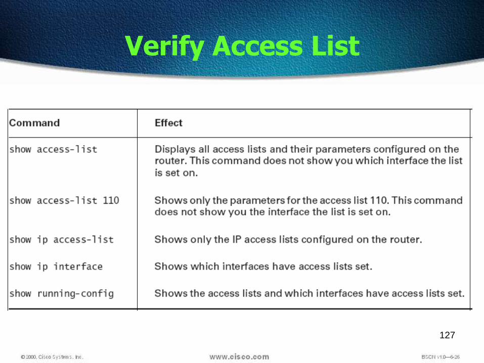
Verify Access List

128
Basic Rules for ACLs
Standard IP access lists should be applied closest to the destination.
Extended IP access lists should be applied closest to the source. Use the inbound or outbound interface reference as if looking at the port
from inside the router. Statements are processed sequentially from the top of list to the bottom
until a match is found, if no match is found then the packet is denied. There is an implicit deny at the end of all access lists. This will not appear
in the configuration listing. Access list entries should filter in the order from specific to general.
Specific hosts should be denied first, and groups or general filters should come last.
Never work with an access list that is actively applied. New lines are always added to the end of the access list. A no access-list x command will remove the whole list. It is not possible
to selectively add and remove lines with numbered ACLs. Outbound filters do not affect traffic originating from the local router.
Related Documents


![Ppt1 [Edited]](https://static.cupdf.com/doc/110x72/545438bfaf795978688b4ce8/ppt1-edited.jpg)