Table of Contents Basic Information ........................................ 9 Conditions Affecting Selection ............................. 10 Mechanical Service Factors ............................. 11-12 How to Select - Quick Selection Method ...................... 13 Quick Selection Shaft Assemblies & Rotations .................. 14 Quick Selection Tables ................................ 15-30 How to Select ......................................... 31 Thermal Factors & Procedures ............................. 32 Selection Examples ..................................... 33 Accessory & Option Information ......................... 34-37 Nomenclature ......................................... 38 How to Order ......................................... 39 Parallel Shaft Type DHC, DHF, DHP, DHJ, DHT, DVA, DVC, DVM Gear Drives Assemblies & Rotations .......................... 40-42 &137 Power & Torque Ratings ......................... 44-53 &138 Basic Thermal Ratings........................... 54-59 &138 LS Shaft Overhung Loads & Thrust Capacities .............. 60-65 Exact Ratios .................................. 66-67 &138 WR 2 ............................................... 68 Dimensions............................... 70-98 &139-141 Right Angle Shaft Type DBB, DBF, DBJ, DBC, DBP, DBT, DHB, DXA, DXC, DXM, DZC, DZT Gear Drives Assemblies & Rotations ........................ 100-101 &142 Power & Torque Ratings ....................... 102-107 &143 Basic Thermal Ratings......................... 108-110 &143 Exact Ratios & WR 2 ........................... 111-112 &143 Dimensions............................. 114-135 &144-146 Accessories ..................................... 147-181 Conversion Factors ................................... 182 Factory Warranty We’re so confident in the performance and reliability of our latest generation of Falk gear drives that we’re backing this comprehensive offering with the best standard warranty in the business. Our full, 3-year Heavy-Duty Warranty provides “shaft-to-shaft” protection on all Falk components – including bearings and seals (warranty extends for 3 years from date of shipment). It’s an industry first... and one more powerful reason why Rexnord is your ultimate bottom-line value. Safety Notes Falk Gear Drives The Falk and Rexnord name on the gear drive is the purchaser’s assurance that the drive was engineered, rated and manufactured to sound design practices. The power supplied to the geared drive must be equal to or less than the power for which the drive was selected using the appropriate mechanical service factor for the application. The customer must assume the responsibility of isolating the gear drive from any vibratory or transient load induced by the driven equipment. Install and operate Rexnord products in conformance with applicable local and national safety codes and per Rexnord installation manuals which are shipped with gear drives and are also available upon request. Suitable guards for rotating members may be purchased from Rexnord as optional accessories. Contact your local Rexnord district office for complete details. People Conveying Equipment Selection of Rexnord gear drives for applications whose primary purpose is the transportation of people is not approved. This includes such applications as freight or passenger elevators, escalators, man lift platforms and ski tows and ski lifts. If the primary purpose of the application is material conveyance and occasionally people are transported, the Rexnord warranty may remain in effect provided the design load conditions are not exceeded and certification to the appropriate safety codes and load conditions has been obtained by the system designer or end user from the appropriate enforcement authorities. Gear Drive Mechanical Power Ratings Gear drive mechanical power ratings stated in this selection guide allow 100% overload for starting loads and momentary overloads associated with normal electric motor driven standard applications operating 10 hours per day under uniform conditions, applications where the recommended mechanical service factor per Page 11 or 12 of this selection guide is 1.00, and where the actual mechanical service factor of the gear drive versus full motor rated power is equal to or greater than 1.00. For other standard applications not meeting conditions stated in the previous paragraph, determine the appropriate mechanical service factor from Page 11 or 12, then calculate an equivalent power by multiplying the actual power transmitted by the previously determined mechanical service factor. For these applications, the mechanical power rating of the gear drive selected must equal or exceed the equivalent power that has been calculated. For non-standard applications, those where excessive overloads, reversing service, mechanical brakes, or oversize prime movers are present, refer to Page 10, Conditions Affecting Selection, for special instructions. Gear Drive Basic Thermal Ratings Gear drive basic thermal ratings stated in this selection guide are based on the following assumed conditions: Ambient temperature is 77°F (25°C). Altitude is between sea level and 2460 feet. Ambient air velocity is between 1.6 fps and 4.6 fps typical of a large indoor room. Duty cycle is continuous. Orientation is floor mounted with shafts in same horizontal plane. Thermal Factors & Procedures, Page 32, permit the calculation of an application adjusted thermal rating for the gear drive when local thermal conditions are different than those stated above. It is not necessary to apply the mechanical service factor to the basic thermal rating when determining the thermal adequacy of a gear drive. Interpolation of Gear Drive Mechanical Power Ratings and Torque Ratings When the high speed shaft rpm for an actual application falls between two tabulated high speed shaft rpm’s found in the selection tables, interpolate to determine gear drive rating. Stored and Inactive Drives Each gear drive is spin-tested with a rust preventive oil that will protect parts against rust for a period of 4 months in an outdoor shelter or 12 months in a dry building after shipment from the Factory. Periodically inspect stored or inactive drives and spray internal parts with rust inhibitor every six months or more often, if necessary. Drain oil before adding rust inhibitor. Indoor dry storage is recommended. Drives ordered for extended storage can be treated at the Factory with a special preservative and sealed to rust-proof parts for periods longer than those cited above, if specified on the order. Refer to Service Manual 128-014 for preparation of stored and inactive gear drives. © Rexnord Industries, LLC, 2001, 2007. (161-110) 9 Selection Guide 161-110, May 2007 Copyright 2001, 2007, Rexnord Industries, LLC. All Rights Reserved. Litho in U.S.A. DRIVE ONE, RENEW, REXNORD, and STEELFLEX, are registered trademarks. Falk is a trademark of Rexnord. The contents of this selection guide are subject to change without notice or obligation. Information contained herein should be confirmed before placing orders. Basic Information

CATALOGO DRIVE ONE 161110.pdf
Oct 30, 2014
Uploaded from Google Docs
Welcome message from author
This document is posted to help you gain knowledge. Please leave a comment to let me know what you think about it! Share it to your friends and learn new things together.
Transcript
Table of ContentsBasic Information . . . . . . . . . . . . . . . . . . . . . . . . . . . . . . . . . . . . . . . . 9Conditions Affecting Selection . . . . . . . . . . . . . . . . . . . . . . . . . . . . . 10Mechanical Service Factors . . . . . . . . . . . . . . . . . . . . . . . . . . . . . 11-12How to Select - Quick Selection Method . . . . . . . . . . . . . . . . . . . . . . 13Quick Selection Shaft Assemblies & Rotations . . . . . . . . . . . . . . . . . . 14Quick Selection Tables . . . . . . . . . . . . . . . . . . . . . . . . . . . . . . . . 15-30How to Select . . . . . . . . . . . . . . . . . . . . . . . . . . . . . . . . . . . . . . . . . 31Thermal Factors & Procedures . . . . . . . . . . . . . . . . . . . . . . . . . . . . . 32Selection Examples . . . . . . . . . . . . . . . . . . . . . . . . . . . . . . . . . . . . . 33Accessory & Option Information . . . . . . . . . . . . . . . . . . . . . . . . . 34-37Nomenclature . . . . . . . . . . . . . . . . . . . . . . . . . . . . . . . . . . . . . . . . . 38How to Order . . . . . . . . . . . . . . . . . . . . . . . . . . . . . . . . . . . . . . . . . 39
Parallel Shaft Type DHC, DHF, DHP, DHJ, DHT, DVA, DVC,DVM Gear Drives
Assemblies & Rotations . . . . . . . . . . . . . . . . . . . . . . . . . . 40-42 &137Power & Torque Ratings . . . . . . . . . . . . . . . . . . . . . . . . . 44-53 &138Basic Thermal Ratings. . . . . . . . . . . . . . . . . . . . . . . . . . . 54-59 &138LS Shaft Overhung Loads & Thrust Capacities . . . . . . . . . . . . . . 60-65Exact Ratios . . . . . . . . . . . . . . . . . . . . . . . . . . . . . . . . . . 66-67 &138WR2 . . . . . . . . . . . . . . . . . . . . . . . . . . . . . . . . . . . . . . . . . . . . . . . 68Dimensions. . . . . . . . . . . . . . . . . . . . . . . . . . . . . . . 70-98 &139-141
Right Angle Shaft Type DBB, DBF, DBJ, DBC, DBP, DBT, DHB, DXA,DXC, DXM, DZC, DZT Gear Drives
Assemblies & Rotations . . . . . . . . . . . . . . . . . . . . . . . . 100-101 &142Power & Torque Ratings . . . . . . . . . . . . . . . . . . . . . . . 102-107 &143Basic Thermal Ratings. . . . . . . . . . . . . . . . . . . . . . . . . 108-110 &143Exact Ratios & WR2. . . . . . . . . . . . . . . . . . . . . . . . . . . 111-112 &143Dimensions. . . . . . . . . . . . . . . . . . . . . . . . . . . . . 114-135 &144-146Accessories . . . . . . . . . . . . . . . . . . . . . . . . . . . . . . . . . . . . . 147-181Conversion Factors . . . . . . . . . . . . . . . . . . . . . . . . . . . . . . . . . . . 182
Factory Warranty We’re so confident in the performance andreliability of our latest generation of Falk gear drives that we’rebacking this comprehensive offering with the best standardwarranty in the business. Our full, 3-year Heavy-Duty Warrantyprovides “shaft-to-shaft” protection on all Falk components –including bearings and seals (warranty extends for 3 years fromdate of shipment). It’s an industry first... and one more powerfulreason why Rexnord is your ultimate bottom-line value.
Safety NotesFalk Gear Drives The Falk and Rexnord name on the gear driveis the purchaser’s assurance that the drive was engineered, ratedand manufactured to sound design practices.
The power supplied to the geared drive must be equal to or less thanthe power for which the drive was selected using the appropriatemechanical service factor for the application. The customer mustassume the responsibility of isolating the gear drive from any vibratoryor transient load induced by the driven equipment.
Install and operate Rexnord products in conformance with applicablelocal and national safety codes and per Rexnord installation manualswhich are shipped with gear drives and are also available uponrequest. Suitable guards for rotating members may be purchased fromRexnord as optional accessories. Contact your local Rexnord districtoffice for complete details.
People Conveying Equipment Selection of Rexnord gear drives forapplications whose primary purpose is the transportation of people isnot approved. This includes such applications as freight or passengerelevators, escalators, man lift platforms and ski tows and ski lifts.
If the primary purpose of the application is material conveyanceand occasionally people are transported, the Rexnord warrantymay remain in effect provided the design load conditions are notexceeded and certification to the appropriate safety codes andload conditions has been obtained by the system designer or enduser from the appropriate enforcement authorities.
Gear Drive Mechanical Power Ratings Gear drive mechanicalpower ratings stated in this selection guide allow 100% overloadfor starting loads and momentary overloads associated withnormal electric motor driven standard applications operating 10hours per day under uniform conditions, applications where therecommended mechanical service factor per Page 11 or 12 ofthis selection guide is 1.00, and where the actual mechanicalservice factor of the gear drive versus full motor rated power isequal to or greater than 1.00.
For other standard applications not meeting conditions stated in theprevious paragraph, determine the appropriate mechanical servicefactor from Page 11 or 12, then calculate an equivalent power bymultiplying the actual power transmitted by the previouslydetermined mechanical service factor. For these applications, themechanical power rating of the gear drive selected must equal orexceed the equivalent power that has been calculated.
For non-standard applications, those where excessiveoverloads, reversing service, mechanical brakes, or oversizeprime movers are present, refer to Page 10, Conditions AffectingSelection, for special instructions.
Gear Drive Basic Thermal Ratings Gear drive basic thermalratings stated in this selection guide are based on the followingassumed conditions:
Ambient temperature is 77°F (25°C).
Altitude is between sea level and 2460 feet.
Ambient air velocity is between 1.6 fps and 4.6 fps typical of alarge indoor room.
Duty cycle is continuous.
Orientation is floor mounted with shafts in same horizontal plane.
Thermal Factors & Procedures, Page 32, permit the calculation of anapplication adjusted thermal rating for the gear drive when localthermal conditions are different than those stated above. It is notnecessary to apply the mechanical service factor to the basic thermalrating when determining the thermal adequacy of a gear drive.
Interpolation of Gear Drive Mechanical Power Ratings andTorque Ratings When the high speed shaft rpm for an actualapplication falls between two tabulated high speed shaft rpm’s foundin the selection tables, interpolate to determine gear drive rating.
Stored and Inactive Drives Each gear drive is spin-tested witha rust preventive oil that will protect parts against rust for aperiod of 4 months in an outdoor shelter or 12 months in a drybuilding after shipment from the Factory.
Periodically inspect stored or inactive drives and spray internalparts with rust inhibitor every six months or more often, ifnecessary. Drain oil before adding rust inhibitor. Indoor drystorage is recommended.
Drives ordered for extended storage can be treated at the Factorywith a special preservative and sealed to rust-proof parts forperiods longer than those cited above, if specified on the order.
Refer to Service Manual 128-014 for preparation of stored andinactive gear drives.
© Rexnord Industries, LLC, 2001, 2007. (161-110) 9
Selection Guide 161-110, May 2007
Copyright 2001, 2007, Rexnord Industries, LLC. All Rights Reserved. Litho in U.S.A.DRIVE ONE, RENEW, REXNORD, and STEELFLEX, are registered trademarks.Falk is a trademark of Rexnord. The contents of this selection guide are subject to change withoutnotice or obligation. Information contained herein should be confirmed before placing orders.
Basic Information
Non–Standard Selection ProceduresSome applications require special procedures, or are refer to Factory.
Excessive Overloads The maximum momentary or starting loadapplied to the gear drive must not exceed 200% of the rated loadcapacity of the gear drive (100% overload). Rated load capacityof the gear drive is defined as the power rating published in thisselection guide with a mechanical service factor of 1.00. If theactual maximum momentary or starting load exceeds theconditions stated above, calculate an equivalent input powerassociated with the excessive overload by dividing the maximumoverload by two. The gear drive selected must have a rated loadcapacity equal to or greater than the equivalent input power.
Frequency of Starts Starting frequency is an importantconsideration when selecting a gear drive. Applications involving2 to 3 equally spaced starts per hour must utilize a minimum 1.5service factor for unloaded starts, and a minimum 1.75 servicefactor for fully loaded starts. For applications involving more than3 starts per hour, refer to Factory the application specifics such asstarting frequency and maximum starting torque. AC motors alsohave similar limitations. The addition of a fluid coupling as a softstart device would increase the number of allowable starts.
Reversing Service Applications involving either more than 20reversals per 10 hour period, or less than 20 reversals per 10hour period with peak torques greater than 200% of normal loadmust be referred to Factory.
Brake Equipped Applications When a gear drive is equippedwith a “working” brake that is used to decelerate the motion ofthe system and the brake is located between the prime moverand the gear drive, select the gear drive based on the brakerating or the highest equivalent input power, whichever is greater.If the brake is used for holding only and is applied after themotion of the system has come to rest, the brake rating must beless than 200% of the rated load capacity of the gear driveselected for the application. If the brake rating is greater than200% of the rated load capacity, refer the application to theFactory. Also refer to the Factory all applications in which thebrake is located at the output shaft of the gear drive.
Oversize Prime Movers Recommended Mechanical ServiceFactors do not cover applications that require oversize primemovers for high energy or peak loads. Refer such applications tothe Factory for selection of suitable gear drives.
Speed Variation or Multi-Speed Applications — The geardrives offered in this selection guide are designed to operate withsplash lubrication on any single speed application and any ratioshown in the selection guide unless otherwise noted. It is essentialthat all orders indicate the operating speed requirements andratio so that the proper internal oil distribution accessories can besupplied for the specific speed.
Falk gear drives use different oil levels for various gear drivesizes, speeds and ratios. Consequently, to operate an existinggear drive at different speeds from those shown on thenameplate, full application and nameplate information must bereferred to the Factory for review of the lubrication system.
All variable or multi-speed applications will be referred to theEngineering Department to specify lubrication components foradequate lubrication at the slowest speed, without excessivetemperature or churning at the highest speed. It is essential thatall orders indicate minimum and maximum speeds, as well as thespeed duration cycles. A separate motor-driven oil pump (at anextra charge) may be required.
When selecting gear drives for multi-speed or variable speedapplications, determine the speed at which the greatest torque is
developed and select the gear drive on this basis. If the speed isnot listed in the selection table, interpolate to determine the geardrive rating.
Application Adjusted Thermal Rating, Page 32, TheApplication Adjusted Thermal Rating is the actual power that agear drive will transmit continually for 3 hours or more withoutoverheating. Although it is not necessary to apply the mechanicalservice factor when determining thermal adequacy of a geardrive, the Application Adjusted thermal Rating considers thermalfactors associated with the application that will affect the ability ofthe gear drive to dissipate thermal energy. These thermal factorsinclude ambient temperature, altitude above sea level, ambientair velocity, inlet water temperature (when cooling tubes areoffered), gear drive orientation and duty cycle. Thermal factorson Page 32 are used to adjust the Basic Thermal Rating whendetermining the Application Adjusted Thermal Rating.
A check of the application adjusted thermal rating versus theactual power transmitted is necessary for the followingapplications:� Continuous duty application where the gear drive runs
continuously without shutdown for 3 hours or more per day.
� Intermittent duty applications where the gear drive operatesfor 3 hours or more per day, and run time intervals exceedthe duration of the immediately following shutdown intervals.If any run time interval equals or exceeds 3 hours, theapplication is considered continuous duty.
The duty cycle factor permits an upward adjustment of the basicthermal rating associated with intermittent duty applicationsabove, and takes into account simply the % operating time perhour of the gear drive, regardless of duration relationshipbetween run time intervals and down time intervals, and providedno specific run time interval exceeds one hour in duration.
Other short interval intermittent duty applications, not meeting criteriastated above, may generate only modest thermal energy to bedissipated by the gear drive. Refer full application details to the theFactory for selection of the minimum cooling method that is adequate.
Effects of Solar Energy If a drive operates in the sun at ambienttemperatures over 100ºF (38ºC), then special measures must betaken to protect the drive from solar energy. This protection canconsist of a canopy over the gear drive or reflective paint on thegear drive. If neither is possible, a heat exchanger or othercooling device may be required.
Overhung Loads and Thrust Loads Overhung loads and thrustloads must be taken into account when selecting a gear drive. If eitheran overhung load or thrust load is imposed on the gear drive, or ifboth an overhung load and thrust load are applied simultaneously,refer application details to the Factory for correct gear drive selection.
Product Modifications The Factory can supply special productmodifications to suit your application needs. Contact your localRepresentative for housing modifications, special ratios, specialshafts, special mounting orientations, accessory modificationsand other special application requirements.
Seal Housing Grease All gear drives will be shipped with Falk LTGgrease in the seal housing cavities. Where this grease couldcontaminate products produced by customer processes, such as inthe food and drug industries, clearly indicate on your purchase orderthat, “Gear drive seal housing cavities must not contain grease.”
Oil Pump Equipped Application When a gear drive isequipped with an external motor driven oil pump, and theambient temperature falls below 50°F (10°C), or the oil viscosityis in excess of 8000 SSU, an oil heater may be required tomaintain a satisfactory flow rate at startup to prevent bearingfailure. Consult the Factory.
10 (161-110) © Rexnord Industries, LLC, 2001, 2007.
Conditions Affecting Selection
Drawing Symbols The following symbols are used throughoutthe dimensioned drawings.
© Rexnord Industries, LLC, 2001, 2007. (161-110) 11
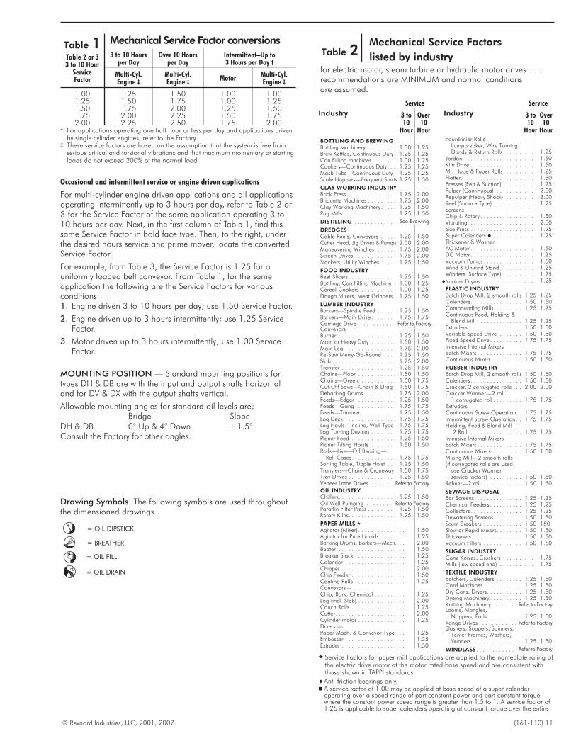
Table 1 Mechanical Service Factor conversions
Table 2 or 33 to 10 Hour
ServiceFactor
3 to 10 Hoursper Day
Over 10 Hoursper Day
Intermittent–Up to3 Hours per Day †
Multi-Cyl.Engine ‡
Multi-Cyl.Engine ‡
MotorMulti-Cyl.Engine ‡
1.00 1.25 1.50 1.00 1.001.25 1.50 1.75 1.00 1.251.50 1.75 2.00 1.25 1.501.75 2.00 2.25 1.50 1.752.00 2.25 2.50 1.75 2.00
† For applications operating one half hour or less per day and applications drivenby single cylinder engines, refer to the Factory.
‡ These service factors are based on the assumption that the system is free fromserious critical and torsional vibrations and that maximum momentary or startingloads do not exceed 200% of the normal load.
Occasional and intermittent service or engine driven applications
For multi-cylinder engine driven applications and all applicationsoperating intermittently up to 3 hours per day, refer to Table 2 or3 for the Service Factor of the same application operating 3 to10 hours per day. Next, in the first column of Table 1, find thissame Service Factor in bold face type. Then, to the right, underthe desired hours service and prime mover, locate the convertedService Factor.
For example, from Table 3, the Service Factor is 1.25 for auniformly loaded belt conveyor. From Table 1, for the sameapplication the following are the Service Factors for variousconditions.1. Engine driven 3 to 10 hours per day; use 1.50 Service Factor.
2. Engine driven up to 3 hours intermittently; use 1.25 ServiceFactor.
3. Motor driven up to 3 hours intermittently; use 1.00 ServiceFactor.
MOUNTING POSITION — Standard mounting positions fortypes DH & DB are with the input and output shafts horizontaland for DV & DX with the output shafts vertical.
Allowable mounting angles for standard oil levels are;Bridge Slope
DH & DB 0° Up & 4° Down � 1.5°Consult the Factory for other angles.
Service
Industry 3 to10
Hour
Over10
Hour
BOTTLING AND BREWINGBottling Machinery . . . . . . . . . 1.00 1.25Brew Kettles, Continuous Duty . 1.25 1.25Can Filling machines . . . . . . . 1.00 1.25Cookers—Continuous Duty . . . 1.25 1.25Mash Tubs—Continuous Duty . 1.25 1.25Scale Hoppers—Frequent Starts 1.25 1.50
CLAY WORKING INDUSTRYBrick Press . . . . . . . . . . . . . . . 1.75 2.00Briquette Machines . . . . . . . . . 1.75 2.00Clay Working Machinery . . . . . 1.25 1.50Pug Mills . . . . . . . . . . . . . . . . 1.25 1.50
DISTILLING . . . . . . . . . . . . See Brewing
DREDGESCable Reels, Conveyors . . . . . 1.25 1.50Cutter Head, Jig Drives & Pumps 2.00 2.00Maneuvering Winches. . . . . . . 1.75 2.00Screen Drives . . . . . . . . . . . . . 1.75 2.00Stackers, Utility Winches . . . . . 1.25 1.50
FOOD INDUSTRYBeet Slicers . . . . . . . . . . . . . . . 1.25 1.50Bottling, Can Filling Machine . 1.00 1.25Cereal Cookers . . . . . . . . . . . 1.00 1.25Dough Mixers, Meat Grinders . 1.25 1.50
LUMBER INDUSTRYBarkers—Spindle Feed . . . . . . 1.25 1.50Barkers—Main Drive . . . . . . . . 1.75 1.75Carriage Drive . . . . . . . . . . . Refer to FactoryConveyorsBurner . . . . . . . . . . . . . . . . . . 1.25 1.50Main or Heavy Duty . . . . . . . . 1.50 1.50Main Log . . . . . . . . . . . . . . . . 1.75 2.00Re-Saw Merry-Go-Round . . . . 1.25 1.50Slab . . . . . . . . . . . . . . . . . . . . 1.75 2.00Transfer . . . . . . . . . . . . . . . . . 1.25 1.50Chains—Floor . . . . . . . . . . . . 1.50 1.50Chains—Green. . . . . . . . . . . . 1.50 1.75Cut-Off Saws—Chain & Drag . 1.50 1.75Debarking Drums . . . . . . . . . . 1.75 2.00Feeds—Edger . . . . . . . . . . . . . 1.25 1.50Feeds—Gang . . . . . . . . . . . . . 1.75 1.75Feeds—Trimmer . . . . . . . . . . . 1.25 1.50Log Deck . . . . . . . . . . . . . . . . 1.75 1.75Log Hauls—Incline, Well Type . 1.75 1.75Log Turning Devices . . . . . . . . 1.75 1.75Planer Feed . . . . . . . . . . . . . . 1.25 1.50Planer Tilting Hoists . . . . . . . . 1.50 1.50Rolls—Live—Off Bearing—
Roll Cases. . . . . . . . . . . . . . 1.75 1.75Sorting Table, Tipple Hoist . . . 1.25 1.50Transfers—Chain & Craneway. 1.50 1.75Tray Drives . . . . . . . . . . . . . . . 1.25 1.50Veneer Lathe Drives . . . . . . . Refer to Factory
OIL INDUSTRYChillers. . . . . . . . . . . . . . . . . . 1.25 1.50Oil Well Pumping . . . . . . . . Refer to FactoryParaffin Filter Press . . . . . . . . . 1.25 1.50Rotary Kilns. . . . . . . . . . . . . . . 1.25 1.50
PAPER MILLS �
Agitator (Mixer) . . . . . . . . . . . . . . . 1.50Agitator for Pure Liquids . . . . . . . . 1.25Barking Drums, Barkers—Mech. . . . 2.00Beater . . . . . . . . . . . . . . . . . . . . . 1.50Breaker Stack . . . . . . . . . . . . . . . . 1.25Calender . . . . . . . . . . . . . . . . . . . 1.25Chipper . . . . . . . . . . . . . . . . . . . . 2.00Chip Feeder . . . . . . . . . . . . . . . . . 1.50Coating Rolls . . . . . . . . . . . . . . . . 1.25Conveyors—Chip, Bark, Chemical . . . . . . . . . . 1.25Log (incl. Slab) . . . . . . . . . . . . . . . 2.00Couch Rolls . . . . . . . . . . . . . . . . . 1.25Cutter. . . . . . . . . . . . . . . . . . . . . . 2.00Cylinder molds . . . . . . . . . . . . . . . 1.25Dryers —Paper Mach. & Conveyor Type . . . 1.25Embosser . . . . . . . . . . . . . . . . . . . 1.25Extruder . . . . . . . . . . . . . . . . . . . . 1.50
Service
Industry 3 to10
Hour
Over10
HourFourdrinier Rolls—
Lumpbreaker, Wire TurningDandy & Return Rolls . . . . . . . . . 1.25
Jordan . . . . . . . . . . . . . . . . . . . . . 1.50Kiln Drive . . . . . . . . . . . . . . . . . . . 1.50Mt. Hope & Paper Rolls . . . . . . . . . 1.25Platter. . . . . . . . . . . . . . . . . . . . . . 1.50Presses (Felt & Suction) . . . . . . . . . 1.25Pulper (Continuous) . . . . . . . . . . . 2.00Repulper (Heavy Shock). . . . . . . . . 2.00Reel (Surface Type) . . . . . . . . . . . . 1.25ScreensChip & Rotary . . . . . . . . . . . . . . . . 1.50Vibrating. . . . . . . . . . . . . . . . . . . . 2.00Size Press . . . . . . . . . . . . . . . . . . . 1.25Super Calenders � . . . . . . . . . . . . 1.25Thickener & WasherAC Motor . . . . . . . . . . . . . . . . . . . 1.50DC Motor . . . . . . . . . . . . . . . . . . . 1.25Vacuum Pumps . . . . . . . . . . . . . . . 1.50Wind & Unwind Stand . . . . . . . . . . 1.25Winders (Surface Type) . . . . . . . . . 1.25
�Yankee Dryers . . . . . . . . . . . . . . . 1.25
PLASTIC INDUSTRYBatch Drop Mill, 2 smooth rolls 1.25 1.25Calenders. . . . . . . . . . . . . . . . 1.50 1.50Compounding Mills . . . . . . . . 1.25 1.25Continuous Feed, Holding &
Blend Mill . . . . . . . . . . . . . . 1.25 1.25Extruders . . . . . . . . . . . . . . . . 1.50 1.50Variable Speed Drive . . . . . . . 1.50 1.50Fixed Speed Drive . . . . . . . . . . 1.75 1.75Intensive Internal MixersBatch Mixers . . . . . . . . . . . . . . 1.75 1.75Continuous Mixers . . . . . . . . . 1.50 1.50
RUBBER INDUSTRYBatch Drop Mill, 2 smooth rolls 1.50 1.50Calenders. . . . . . . . . . . . . . . . 1.50 1.50Cracker, 2 corrugated rolls . . . 2.00 2.00Cracker Warmer—2 roll.
1 corrugated roll . . . . . . . . . 1.75 1.75ExtrudersContinuous Screw Operation. . 1.75 1.75Intermittent Screw Operation . . 1.75 1.75Holding, Feed & Blend Mill—
2 Roll. . . . . . . . . . . . . . . . . 1.25 1.25Intensive Internal MixersBatch Mixers . . . . . . . . . . . . . . 1.75 1.75Continuous Mixers . . . . . . . . . 1.50 1.50Mixing Mill—2 smooth rolls(if corrugated rolls are used.
use Cracker Warmerservice factors) . . . . . . . . . . 1.50 1.50
Refiner—2 roll . . . . . . . . . . . . 1.50 1.50
SEWAGE DISPOSALBar Screens . . . . . . . . . . . . . . 1.25 1.25Chemical Feeders . . . . . . . . . . 1.25 1.25Collectors . . . . . . . . . . . . . . . . 1.25 1.25Dewatering Screens. . . . . . . . . 1.50 1.50Scum Breakers . . . . . . . . . . . . 1.50 150Slow or Rapid Mixers. . . . . . . . 1.50 1.50Thickeners . . . . . . . . . . . . . . . 1.50 1.50Vacuum Filters . . . . . . . . . . . . 1.50 1.50
SUGAR INDUSTRYCane Knives, Crushers . . . . . . . . . 1.75Mills (low speed end) . . . . . . . . . . 1.75
TEXTILE INDUSTRYBatchers, Calenders . . . . . . . . 1.25 1.50Card Machines . . . . . . . . . . . . 1.25 1.50Dry Cans, Dryers. . . . . . . . . . . 1.25 1.50Dyeing Machinery . . . . . . . . . . 1.25 1.50Knitting Machinery . . . . . . . . Refer to FactoryLooms, Mangles,
Nappers, Pads. . . . . . . . . . . 1.25 1.50Range Drives . . . . . . . . . . . . Refer to FactorySlashers, Soapers, Spinners,
Tenter Frames, Washers,Winders . . . . . . . . . . . . . . . 1.25 1.50
WINDLASS. . . . . . . . . . . . Refer to Factory
Table 2Mechanical Service Factors
listed by industryfor electric motor, steam turbine or hydraulic motor drives . . .recommendations are MINIMUM and normal conditionsare assumed.
� Service Factors for paper mill applications are applied to the nameplate rating ofthe electric drive motor at the motor rated base speed and are consistent withthose shown in TAPPI standards.
�Anti-friction bearings only.� A service factor of 1.00 may be applied at base speed of a super calender
operating over a speed range of part constant power and part constant torquewhere the constant power speed range is greater than 1.5 to 1. A service factor of1.25 is applicable to super calenders operating at constant torque over the entire
= OIL DIPSTICK
= BREATHER
= OIL FILL
= OIL DRAIN
12 (161-110) © Rexnord Industries, LLC, 2001, 2007.
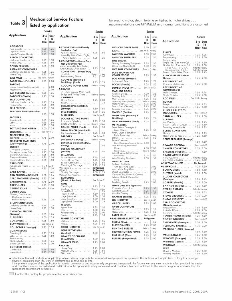
Table 3Mechanical Service Factors
listed by application
for electric motor, steam turbine or hydraulic motor drives . . .recommendations are MINIMUM and normal conditions are assumed
Service
Application 3 to10
Hour
Over10
Hour
AGITATORSPure Liquids . . . . . . . . . . . . . . 1.00 1.25Liquids & Solids . . . . . . . . . . . 1.25 1.50Liquids-Variable Density . . . . . 1.25 1.50
APRON CONVEYORSUniformly Loaded or Fed. . . . . 1.25 1.50Heavy Duty . . . . . . . . . . . . . . . 1.25 1.50
APRON FEEDERS . . . . . . . . 1.25 1.50
ASSEMBLY CONVEYORSUniformly Loaded or Fed. . . . . 1.25 1.25Heavy Duty . . . . . . . . . . . . . . . 1.25 1.50
BALL MILLS . . . . . . . . . . . See Mills. Rotary
BARGE HAUL PULLERS . . . 1.75 2.00
BARKINGDrums (Coupling Connected) . . . . 2.00Mechanical. . . . . . . . . . . . . . . . . . 2.00
BAR SCREENS (Sewage) . . 1.25 1.25
BATCHERS (Textile) . . . . . . 1.25 1.50
BELT CONVEYORSUniformly Loaded or Fed. . . . . 1.25 1.25Heavy Duty . . . . . . . . . . . . . . . 1.25 1.50
BELT FEEDERS . . . . . . . . . . 1.25 1.50
BENDING ROLLS (Machine)1.25 1.50
BLOWERSCentrifugal . . . . . . . . . . . . . . . 1.25 1.25Lobe. . . . . . . . . . . . . . . . . . . . 1.25 1.50Vane . . . . . . . . . . . . . . . . . . . 1.25 1.50
BOTTLING MACHINERY . . 1.00 1.25
BREWING . . . . . . . . . . . . . . See Table 2
BRICK PRESS (ClayWorking) . . . . . . . . . . . . . . 1.75 2.00
BRIQUETTE MACHINES(Clay Working) . . . . . . . . . 1.75 2.00
BUCKETConveyors Uniform . . . . . . . . . 1.25 1.50Conveyors Heavy Duty . . . . . . 1.25 1.50Elevators Continuous . . . . . . . 1.25 1.50Elevators Uniform . . . . . . . . . . 1.25 1.50Elevators Heavy Duty. . . . . . . . 1.25 1.50
CALENDERSRubber and Plastic . . . . . . . . . See Table 2Textile. . . . . . . . . . . . . . . . . . . 1.25 1.50
CANE KNIVES . . . . . . . . . . . . . 1.75
CAN FILLING MACHINES. 1.00 1.25
CARD MACHINES (Textile) 1.25 1.50
CAR DUMPERS. . . . . . . . . . 1.75 2.00
CAR PULLERS . . . . . . . . . . . 1.25 1.50
CEMENT KILNS . . . . . . . . See Mills. Rotary
CENTRIFUGALBlowers, Compressors,
Discharge Elevators,Fans or Pumps . . . . . . . . . . 1.25 1.25
CHAIN CONVEYORSUniformly Loaded or Fed. . . . . 1.25 1.25Heavy Duty . . . . . . . . . . . . . . . 1.25 1.50
CHEMICAL FEEDERS(Sewage) . . . . . . . . . . . . . . 1.25 1.25
CLARIFIERS . . . . . . . . . . . . 1.00 1.25
CLASSIFIERS . . . . . . . . . . . 1.25 1.50
CLAY WORKING . . . . . . . . See Table 2
COLLECTORS (Sewage) . . 1.25 1.25
COMPRESSORSCentrifugal . . . . . . . . . . . . . . . 1.25 1.25Lobe. . . . . . . . . . . . . . . . . . . . 1.25 1.50Reciprocating .Multi-Cylinder. . . . . . . . . . . . . 1.50 1.75Single-Cylinder . . . . . . . . . . . . 1.75 2.00
CONCRETE MIXERSContinuous. . . . . . . . . . . . . . . 1.25 1.50Intermittent . . . . . . . . . . . . . . . 1.25 1.50
Service
Application 3 to10
Hour
Over10
Hour� CONVEYORS—Uniformly
loaded or Fed:Apron or Bucket. . . . . . . . . . . . 1.25 1.50Assembly, Belt, Chain, Flight,
Oven, Screw . . . . . . . . . . . . 1.25 1.25
� CONVEYORS—Heavy Duty.Not Uniformly Fed
Apron, Assembly, Belt, Bucket,Chain, Flight, Oven, Screw . . . . 1.25 1.50
CONVEYORS—Severe DutyLive Roll . . . . . . . . . . . . . . . . Refer to FactoryReciprocating Shaker . . . . . . . 1.5 2.00
COOKERS (Brewing &Distilling), (food) . . . . . . . . 1.25 1.25
COOLING TOWER FANS Refer to Factory
� CRANES
Dry Dock Cranes, Main Hoist,Bridge and Trolley Travel . . . Refer to Factory
CRUSHERSOre or Stone . . . . . . . . . . . . . 1.75 2.00Sugar . . . . . . . . . . . . . . . . . . . . . . 1.75
DEWATERING SCREENS(Sewage) . . . . . . . . . . . . . . 1.50 1.50
DISC FEEDERS . . . . . . . . . . 1.00 1.25
DISTILLING . . . . . . . . . . . . See Table 2
DOUBLE ACTING PUMPS2 or more Cylinders . . . . . . . . 1.25 1.50Single Cylinder . . . . . . . . . . . .Refer to Factory
DOUGH MIXER (Food) . . . 1.25 1.50
DRAW BENCH (Metal Mills)Carriage & Main Drive . . . . . 1.25 1.50
DREDGES . . . . . . . . . . . . . . See Table 2
DRY DOCK CRANES . . . . Refer to Factory
DRYERS & COOLERS (Mills.Rotary) . . . . . . . . . . . . . . . . . . . 1.50
DYEING MACHINERY(Textile) . . . . . . . . . . . . . . . 1.25 1.50
ELEVATORSBucket-Uniform Lood . . . . . . . 1.25 1.50Bucket-Heavy Duty . . . . . . . . . 1.25 1.50Bucket-Continuous . . . . . . . . . 1.25 1.50Centrifugal Discharge . . . . . . . 1.25 1.25
� Escalators . . . . . . . . . . . . . . . Not Approved� Freight . . . . . . . . . . . . . . . . . Not Approved
Gravity Discharge . . . . . . . . . . 1.00 1.25� Man Lifts, Passenger . . . . . . . Not Approved
EXTRUDERS(Plastic & Rubber) . . . . . . . See Table 2
FANSCentrifugal . . . . . . . . . . . . . . . 1.25 1.25Cooling Towers . . . . . . . . . . Refer to FactoryForced Draft . . . . . . . . . . . . . . . . . 1.25Induced Draft . . . . . . . . . . . . . 1.50 1.50Large (Mine. etc.) . . . . . . . . . . 1.50 1.50Large lndustrial . . . . . . . . . . . . 1.50 1.50Light (Small Diameter) . . . . . . . 1.00 1.25
FEEDERSApron. Belt . . . . . . . . . . . . . . . 1.25 1.50Disc . . . . . . . . . . . . . . . . . . . . 1.00 1.25Reciprocating . . . . . . . . . . . . . 1.75 2.00Screw . . . . . . . . . . . . . . . . . . . 1.25 1.50
FLIGHT CONVEYORSUniform . . . . . . . . . . . . . . . . . 1.25 1.25Heavy. . . . . . . . . . . . . . . . . . . 1.25 1.50
FOOD INDUSTRY . . . . . . . See Table 2
GENERATORS (NotWelding) . . . . . . . . . . . . . . 1.00 1.25
GRAVITY DISCHARGEELEVATORS . . . . . . . . . . . . 1.00 1.25
HAMMER MILLS . . . . . . . . . 1.75 2.00
� HOISTSHeavy Duty . . . . . . . . . . . . . . . 1.75 2.00Medium Duty . . . . . . . . . . . . . 1.25 1.50Skip Hoist . . . . . . . . . . . . . . . . 1.25 1.50
Service
Application 3 to10
Hour
Over10
Hour
INDUCED DRAFT FANS . . 1.50 1.50
KILNS . . . . . . . . . . . . . . . . See Mills. Rotary
LAUNDRY WASHERS. . . . . 1.50 2.00
LAUNDRY TUMBLERS . . . . 1.25 1.50
LINE SHAFTSDriving Processing Equipment . 1.25 1.50Other Line Shafts, Light . . . . . . 1.00 1.25
LIVE ROLL CONVEYORS Refer to Factory
LOBE BLOWERS ORCOMPRESSORS . . . . . . . . . 1.25 1.50
LOG HAULS (Lumber)Incline-well Type . . . . . . . . . . . 1.75 1.75
LOOMS (Textile) . . . . . . . . 1.25 1.50
LUMBER INDUSTRY . . . . . . See Table 2
MACHINE TOOLSAuxiliary Drives . . . . . . . . . . . . 1.00 1.25Bending Rolls . . . . . . . . . . . . . 1.25 1.50Main Drives . . . . . . . . . . . . . . 1.25 1.50Notching Press (Belted). . . . . Refer to FactoryPlate Planers . . . . . . . . . . . . . . 1.75 2.00Punch Press (Geared) . . . . . . . 1.75 2.00Tapping machines. . . . . . . . . . 1.75 2.00
MANGLE (Textile) . . . . . . . 1.25 1.50
MASH TUBS (Brewing &Distilling) . . . . . . . . . . . . . . 1.25 1.25
MEAT GRINDERS (Food) . . 1.25 1.50
METAL MILLSDraw Bench Carriages &
Main Drives. . . . . . . . . . . . . 1.25 1.50Pinch, Dryer & Scrubber
Rolls, Reversing . . . . . . . . . .Refer to FactorySlitters . . . . . . . . . . . . . . . . . . 1.25 1.50Table Conveyors.
Non-Reversing Group Drives 1.50 1.50Non-Reversing Individual
Drives . . . . . . . . . . . . . . . . . 2.00 2.00Reversing . . . . . . . . . . . Refer to Factory
Wire Drawing & FlatteningMachines . . . . . . . . . . . . . . 1.25 1.50
Wire Winding Machines . . . . . 1.50 1.50
MILLS. ROTARYBall and Rod Mills
with Spur Ring Gear . . . . . . . . . 2.00with Helical Ring Gear . . . . . . . . . 1.50Direct Connected . . . . . . . . . . . . . 2.00Cement Kilns, Dryers & Coolers . . . 1.50Pebble, Plain & Wedge Bar
Mills . . . . . . . . . . . . . . . . . . . . . 1.50Tumbling Barrels. . . . . . . . . . . 1.75 2.00
MIXER (Also see Agitators)Concrete, Cont. & lnt.. . . . . . . 1.25 1.50Constant Density. . . . . . . . . . . 1.25 1.50Variable Density . . . . . . . . . . . 1.25 1.50
NAPPERS (Textile) . . . . . . . 1.25 1.50
OIL INDUSTRY . . . . . . . . . . See Table 2
ORE CRUSHERS . . . . . . . . . 1.75 2.00
OVEN CONVEYORSUniform . . . . . . . . . . . . . . . . . 1.25 1.25Heavy Duty . . . . . . . . . . . . . . . 1.25 1.50
PAPER MILLS . . . . . . . . . . . See Table 2
� PASSENGER ELEVATORS . . Not Approved
PEBBLE MILLS. . . . . . . . . . . . . . 1.50
PLATE PLANERS . . . . . . . . . 1.75 2.00
PRINTING PRESSES . . . . . Refer to Factory
PROPORTIONING PUMPS 1.25 1.50
PUG MILLS (Clay) . . . . . . . 1.25 1.50
PULLERS (Barge Haul) . . . 1.75 2.00
Service
Application 3 to10
Hour
Over10
Hour
PUMPSCentrifugal . . . . . . . . . . . . . . . 1.25 1.25Proportioning . . . . . . . . . . . . . 1.25 1.50ReciprocatingSingle Act., 3 or more Cyl. . . . 1.25 1.50Double Act., 2 or more Cyl. . . 1.25 1.50
Single Act., 1 or 2 Cyl. . Refer to FactoryDouble Acting, 1 Cyl. . . Refer to Factory
Rotary: Gear, Lobe, Vane . . . . 1.00 1.25
PUNCH PRESSES (GearDriven) . . . . . . . . . . . . . . . . 1.75 2.00
RECIPROCATINGConveyors & Feeders . . . . . . 1.75 2.00
RECIPROCATINGCOMPRESSORSMultI-Cylinder. . . . . . . . . . . . . 1.50 1.75Single Cylinder . . . . . . . . . . . . 1.75 2.00
ROD MILLS . . . . . . . . . . . See Mills. Rotary
ROTARYPumps . . . . . . . . . . . . . . . . . . 1.00 1.25Screens (Sand or Gravel). . . . . 1.25 1.50
RUBBER & PLASTICSINDUSTRIES . . . . . . . . . . . . See Table 2
SAND MULLERS . . . . . . . . . 1.25 1.50
SCREENSAir Washing . . . . . . . . . . . . . . 1.00 1.25Rotary—Sand or Gravel . . . . . 1.25 1.50Traveling Water Intake . . . . . . 1.00 1.25
SCREW CONVEYORSUniform . . . . . . . . . . . . . . . . . 1.25 1.25Heavy Duty or Feeder . . . . . . . 1.25 1.50
SCUM BREAKERS (Sewage)1.50 1.50
SEWAGE DISPOSAL . . . . . See Table 2
SHAKER CONVEYORS . . . 1.75 2.00
SHEETERS (Rubber) . . . . . . . . . 1.50
SINGLE ACTING PUMPI or 2 Cylinders . . . . . . . . . . Refer to Factory3 or more Cylinders . . . . . . . . 1.25 1.50
� SKI TOWS & LIFTS . . . . . . . Not Approved
� SKIP HOIST . . . . . . . . . . . . 1.25 1.50
SLAB PUSHERS . . . . . . . . . 1.50 1.50
SLITTERS (Metal) . . . . . . . . 1.25 1.50
SLUDGE COLLECTORS(Sewage) . . . . . . . . . . . . . . 1.25 1.25
SOAPERS (Textile) . . . . . . . 1.25 1.50
SPINNERS (Textile) . . . . . . 1.25 1.50
STEERING GEARS . . . . . . Refer to Factory
STOKERS . . . . . . . . . . . . . . 1.00 1.25
STONE CRUSHERS . . . . . . 1.75 2.00
SUGAR INDUSTRY. . . . . . . See Table 2
TABLE CONVEYORS(Non-Reversing)Group Drives . . . . . . . . . . . . . 1.50 1.50Individual Drives . . . . . . . . . . . 2.00 2.00Reversing . . . . . . . . . . . . . . . Refer to Factory
TENTER FRAMES (Textile) . 1.25 1.50
TEXTILE INDUSTRY . . . . . . See Table 2
THICKENERS (Sewage) . . . 1.50 1.50
TUMBLING BARRELS . . . . . 1.75 2.00
VACUUM FILTERS (Sewage)1.50 1.50
VANE BLOWERS . . . . . . . . 1.25 1.50
WINCHES (Dredges) . . . . . 1.25 1.50
WINDERS (Textile). . . . . . . 1.25 1.50
WINDLASS . . . . . . . . . . . . . Refer to Factory
WIREDrawing Machines . . . . . . . . . 1.25 1.50Winding Machines . . . . . . . . . 1.50 1.50
� Selection of Rexnord products for applications whose primary purpose is the transportation of people is not approved. This includes such applications as freight or passengerelevators, escalators, man lifts, work lift platforms and ski tows and ski lifts.If the primary purpose of the application is material conveyance and occasionally people are transported, the Factory warranty may remain in effect provided the designload conditions are not exceeded and certification to the appropriate safety codes and load conditions has been obtained by the system designer or end user from theappropriate enforcement authorities.
Contact the Factory for proper selection of a mixer drive.
Selection InformationThis section contains the Quick Selection Method.
Before proceeding, determine if your application meets thefollowing guidelines.� 1750 rpm input
� Standard ratios for double and triple reductions
� 77°F ambient at sea level
NOTE: If the above guidelines cannot be met, refer to Factory.Also, if you have an unusual application involving any of thefollowing conditions refer to Page 10.� Excessive Overloads
� Reversing Service
� Brake Equipped Applications
� Oversized Prime Movers
� Multi-Speed or Variable Speed Applications
� Thermal Rating Application Factors
� Excessive Overhung Loads or Thrust Loads
� Product Modifications
How to Select By Quick Selection1. Determine Service Factor — See Tables 2 & 3.
2. Determine Motor Horsepower
3. Determine Drive Output Speed.
4. Select Drive Size — Use Quick Selection Tables, Pages 15 thru30; find the table for your motor horsepower and locate thecorrect drive size opposite the nearest output rpm and therequired service factor determined in Steps 1 thru 3.
5. Select Drive Configuration — Type DH or DB
6. Check Minimum Cooling Required. If a required coolingaccessory is not acceptable check a larger size drive
7. Check Drive Dimensions — Pages 74 thru 78.
8. Place the Order.
ExampleApplication: Belt conveyor, heavy duty, head shaft speed is 80 rpmambient temperature 100°F(38°C) at sea level.
Duty Cycle: 16 hours per day.
Driver: 50 hp electric motor, 1750 rpm.
Output: Coupling connected.1. Service Factor from Page 12 is 1.50.
2. Motor Horsepower is 50 hp.
3. From Page 15, in the 50 hp Quick Selection Table, the correctselection is a Size M1130DH2, 22.07:1 exact ratio drive.
4. From Page 14, the desired configuration is assembly 0016 or0025.
5. No cooling accessory is required.
6. Check Dimensions on Page 74.
© Rexnord Industries, LLC, 2001, 2007. (161-110) 13
How to Select/Quick Selection Method
14 (161-110) © Rexnord Industries, LLC, 2001, 2007.
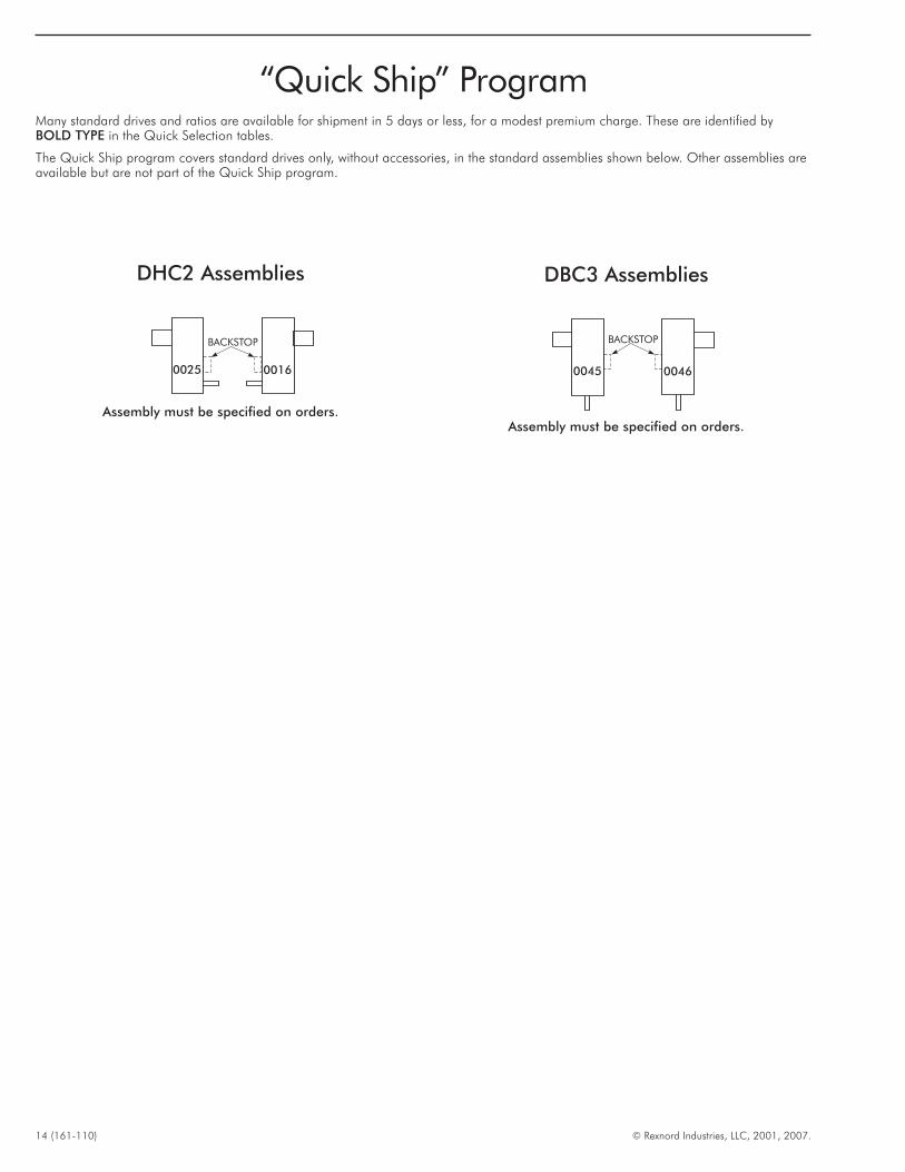
“Quick Ship” ProgramMany standard drives and ratios are available for shipment in 5 days or less, for a modest premium charge. These are identified byBOLD TYPE in the Quick Selection tables.
The Quick Ship program covers standard drives only, without accessories, in the standard assemblies shown below. Other assemblies areavailable but are not part of the Quick Ship program.
DHC2 Assemblies
0025 0016
BACKSTOP
Assembly must be specified on orders.
DBC3 Assemblies
0045 0046
BACKSTOP
Assembly must be specified on orders.
© Rexnord Industries, LLC, 2001, 2007. (161-110) 15
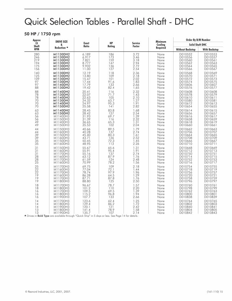
Quick Selection Tables - Parallel Shaft - DHC50 HP / 1750 rpm
ApproxLS
ShaftRPM
DRIVE SIZE&
Reduction �
ExactRatio
HPRating
ServiceFactor
MinimumCooling
Required
Order By B/M Number
Solid Shaft DHC
Without Backstop With Backstop
280 M1130DH2 6.189 186 3.72 None D010552 D010553246 M1130DH2 6.917 173 3.46 None D010556 D010557219 M1130DH2 7.821 159 3.18 None D010560 D010561194 M1130DH2 8.777 147 2.94 None D010562 D010563175 M1130DH2 9.932 136 2.72 None D010564 D010565156 M1130DH2 11.00 127 2.54 None D010566 D010567
140 M1130DH2 12.19 118 2.36 None D010568 D010569125 M1130DH2 13.80 109 2.18 None D010570 D010571109 M1130DH2 15.47 101 2.02 None D010572 D01057397 M1130DH2 17.44 91.6 1.83 None D010574 D01057597 M1140DH2 17.79 133 2.66 None D010606 D01060788 M1130DH2 19.42 82.4 1.65 None D010576 D010577
88 M1140DH2 20.41 116 2.32 None D010608 D01060878 M1130DH2 22.07 71.7 1.43 None D010578 D01057978 M1140DH2 22.63 105 2.10 None D010610 D01061170 M1130DH2 24.32 63.7 1.27 None D010580 D01058170 M1140DH2 24.97 95.3 1.91 None D010612 D01061370 M1150DH2 25.58 141 2.82 None D010654 D010655
63 M1140DH2 28.45 83.8 1.68 None D010614 D01061563 M1150DH2 28.42 127 2.54 None D010656 D01065756 M1140DH3 31.93 69.7 1.39 None D010616 D01061756 M1150DH3 31.39 116 2.32 None D010658 D01065949 M1140DH3 36.65 65.3 1.31 None D010618 D01061949 M1150DH3 35.53 102 2.04 None D010660 D010661
44 M1150DH3 40.66 89.5 1.79 None D010662 D01066344 M1160DH3 40.28 137 2.74 None D010706 D01070739 M1150DH3 45.40 80.3 1.61 None D010664 D01066539 M1160DH3 43.71 126 2.52 None D010708 D01070935 M1150DH3 50.45 72.3 1.45 None D010666 D01066735 M1160DH3 48.95 113 2.26 None D010710 D010711
31 M1150DH3 55.67 65.6 1.31 None D010668 D01066931 M1160DH3 55.91 95.4 1.91 None D010712 D01071331 M1170DH3 55.16 137 2.74 None D010750 D01075128 M1160DH3 63.12 87.9 1.76 None D010714 D01071528 M1170DH3 61.59 124 2.48 None D010752 D01075325 M1160DH3 70.99 78.2 1.56 None D010716 D010717
25 M1170DH3 69.75 109 2.18 None D010754 D01075522 M1160DH3 77.04 72.1 1.44 None D010718 D01071922 M1170DH3 78.74 97.9 1.96 None D010756 D01075719 M1160DH3 86.28 64.5 1.29 None D010720 D01072119 M1170DH3 87.71 87.8 1.76 None D010758 D01075919 M1180DH3 88.80 125 2.50 None D010796 D010797
18 M1170DH3 96.67 78.7 1.57 None D010760 D01076118 M1180DH3 101.2 110 2.20 None D010798 D01079916 M1170DH3 109.5 69.5 1.39 None D010762 D01076316 M1180DH3 115.2 96.8 1.94 None D010800 D01080116 M1190DH3 107.7 133 2.66 None D010838 D010839
14 M1170DH3 123.6 62.4 1.25 None D010764 D01076514 M1180DH3 129.4 86.2 1.72 None D010802 D01080314 M1190DH3 120.1 121 2.42 None D010840 D01084113 M1180DH3 141.4 78.9 1.58 None D010804 D01080513 M1190DH3 135.7 107 2.14 None D010842 D010843
� Drives in Bold Type are available through “Quick Ship” in 5 days or less. See Page 14 for details.
16 (161-110) © Rexnord Industries, LLC, 2001, 2007.
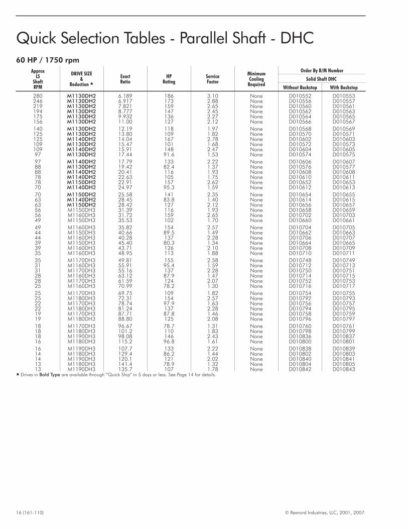
Quick Selection Tables - Parallel Shaft - DHC60 HP / 1750 rpm
ApproxLS
ShaftRPM
DRIVE SIZE&
Reduction �
ExactRatio
HPRating
ServiceFactor
MinimumCooling
Required
Order By B/M Number
Solid Shaft DHC
Without Backstop With Backstop
280 M1130DH2 6.189 186 3.10 None D010552 D010553246 M1130DH2 6.917 173 2.88 None D010556 D010557219 M1130DH2 7.821 159 2.65 None D010560 D010561194 M1130DH2 8.777 147 2.45 None D010562 D010563175 M1130DH2 9.932 136 2.27 None D010564 D010565156 M1130DH2 11.00 127 2.12 None D010566 D010567
140 M1130DH2 12.19 118 1.97 None D010568 D010569125 M1130DH2 13.80 109 1.82 None D010570 D010571125 M1140DH2 14.04 167 2.78 None D010602 D010603109 M1130DH2 15.47 101 1.68 None D010572 D010573109 M1140DH2 15.91 148 2.47 None D010604 D01060597 M1130DH2 17.44 91.6 1.53 None D010574 D010575
97 M1140DH2 17.79 133 2.22 None D010606 D01060788 M1130DH2 19.42 82.4 1.37 None D010576 D01057788 M1140DH2 20.41 116 1.93 None D010608 D01060878 M1140DH2 22.63 105 1.75 None D010610 D01061178 M1150DH2 22.91 157 2.62 None D010652 D01065370 M1140DH2 24.97 95.3 1.59 None D010612 D010613
70 M1150DH2 25.58 141 2.35 None D010654 D01065563 M1140DH2 28.45 83.8 1.40 None D010614 D01061563 M1150DH2 28.42 127 2.12 None D010656 D01065756 M1150DH3 31.39 116 1.93 None D010658 D01065956 M1160DH3 31.72 159 2.65 None D010702 D01070349 M1150DH3 35.53 102 1.70 None D010660 D010661
49 M1160DH3 35.82 154 2.57 None D010704 D01070544 M1150DH3 40.66 89.5 1.49 None D010662 D01066344 M1160DH3 40.28 137 2.28 None D010706 D01070739 M1150DH3 45.40 80.3 1.34 None D010664 D01066539 M1160DH3 43.71 126 2.10 None D010708 D01070935 M1160DH3 48.95 113 1.88 None D010710 D010711
35 M1170DH3 49.81 155 2.58 None D010748 D01074931 M1160DH3 55.91 95.4 1.59 None D010712 D01071331 M1170DH3 55.16 137 2.28 None D010750 D01075128 M1160DH3 63.12 87.9 1.47 None D010714 D01071528 M1170DH3 61.59 124 2.07 None D010752 D01075325 M1160DH3 70.99 78.2 1.30 None D010716 D010717
25 M1170DH3 69.75 109 1.82 None D010754 D01075525 M1180DH3 72.31 154 2.57 None D010792 D01079322 M1170DH3 78.74 97.9 1.63 None D010756 D01075722 M1180DH3 81.24 137 2.28 None D010794 D01079519 M1170DH3 87.71 87.8 1.46 None D010758 D01075919 M1180DH3 88.80 125 2.08 None D010796 D010797
18 M1170DH3 96.67 78.7 1.31 None D010760 D01076118 M1180DH3 101.2 110 1.83 None D010798 D01079918 M1190DH3 98.08 146 2.43 None D010836 D01083716 M1180DH3 115.2 96.8 1.61 None D010800 D010801
16 M1190DH3 107.7 133 2.22 None D010838 D01083914 M1180DH3 129.4 86.2 1.44 None D010802 D01080314 M1190DH3 120.1 121 2.02 None D010840 D01084113 M1180DH3 141.4 78.9 1.32 None D010804 D01080513 M1190DH3 135.7 107 1.78 None D010842 D010843
� Drives in Bold Type are available through “Quick Ship” in 5 days or less. See Page 14 for details.
© Rexnord Industries, LLC, 2001, 2007. (161-110) 17
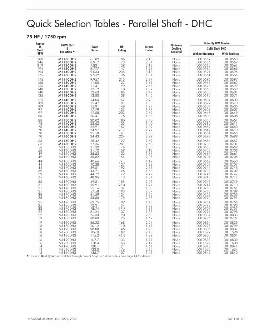
Quick Selection Tables - Parallel Shaft - DHC75 HP / 1750 rpm
ApproxLS
ShaftRPM
DRIVE SIZE&
Reduction �
ExactRatio
HPRating
ServiceFactor
MinimumCooling
Required
Order By B/M Number
Solid Shaft DHC
Without Backstop With Backstop
280 M1130DH2 6.189 186 2.48 None D010552 D010553246 M1130DH2 6.917 173 2.31 None D010556 D010557219 M1130DH2 7.821 159 2.12 None D010560 D010561194 M1130DH2 8.777 147 1.96 None D010562 D010563194 M1140DH2 9.033 235 3.13 None D010594 D010595175 M1130DH2 9.932 136 1.81 None D010564 D010565
175 M1140DH2 9.957 215 2.87 None D010596 D010597156 M1130DH2 11.00 127 1.69 None D010566 D010567156 M1140DH2 11.41 199 2.65 None D010598 D010599140 M1130DH2 12.19 118 1.57 None D010568 D010569140 M1140DH2 12.63 185 2.47 None D010600 D010601125 M1130DH2 13.80 109 1.45 None D010570 D010571
125 M1140DH2 14.04 167 2.23 None D010602 D010603109 M1130DH2 15.47 101 1.35 None D010572 D010573109 M1140DH2 15.91 148 1.97 None D010604 D01060597 M1140DH2 17.79 133 1.77 None D010606 D01060797 M1150DH2 17.68 202 2.69 None D010648 D01064988 M1140DH2 20.41 116 1.55 None D010608 D010608
88 M1150DH2 20.02 180 2.40 None D010650 D01065178 M1140DH2 22.63 105 1.40 None D010610 D01061178 M1150DH2 22.91 157 2.09 None D010652 D01065370 M1140DH2 24.97 95.3 1.27 None D010612 D01061370 M1150DH2 25.58 141 1.88 None D010654 D01065570 M1160DH2 24.43 224 2.99 None D010698 D010699
63 M1150DH2 28.42 127 1.69 None D010656 D01065763 M1160DH2 27.36 201 2.68 None D010700 D01070156 M1150DH3 31.39 116 1.55 None D010658 D01065956 M1160DH3 31.72 159 2.12 None D010702 D01070349 M1150DH3 35.53 102 1.36 None D010660 D01066149 M1160DH3 35.82 154 2.05 None D010704 D010705
44 M1150DH3 40.66 89.5 1.19 None D010662 D01066344 M1160DH3 40.28 137 1.83 None D010706 D01070744 M1170DH3 39.61 192 2.56 None D010744 D01074539 M1160DH3 43.71 126 1.68 None D010708 D01070939 M1170DH3 44.72 172 2.29 None D010746 D01074735 M1160DH3 48.95 113 1.51 None D010710 D010711
35 M1170DH3 49.81 155 2.07 None D010748 D01074931 M1160DH3 55.91 95.4 1.27 None D010712 D01071331 M1170DH3 55.16 137 1.83 None D010750 D01075131 M1180DH3 57.58 193 2.57 None D010788 D01078928 M1170DH3 61.59 124 1.65 None D010752 D01075328 M1180DH3 63.55 175 2.33 None D010790 D010791
25 M1170DH3 69.75 109 1.45 None D010754 D01075525 M1180DH3 72.31 154 2.05 None D010792 D01079322 M1170DH3 78.74 97.9 1.31 None D010756 D01075722 M1180DH3 81.24 137 1.83 None D010794 D01079522 M1190DH3 76.33 190 2.53 None D010832 D01083319 M1180DH3 88.80 125 1.67 None D010796 D010797
19 M1190DH3 86.22 168 2.24 None D010834 D01083518 M1180DH3 101.2 110 1.47 None D010798 D01079918 M1190DH3 98.08 146 1.95 None D010836 D01083718 M1200DH3 106.0 182 2.43 None D011597 D01159816 M1180DH3 115.2 96.8 1.29 None D010800 D010801
16 M1190DH3 107.7 133 1.77 None D010838 D01083916 M1200DH3 118.4 163 2.17 None D011599 D01160014 M1190DH3 120.1 121 1.61 None D010840 D01084114 M1210DH3 133.0 176 2.35 None D011623 D01162413 M1190DH3 135.7 107 1.43 None D010842 D010843
� Drives in Bold Type are available through “Quick Ship” in 5 days or less. See Page 14 for details.
18 (161-110) © Rexnord Industries, LLC, 2001, 2007.
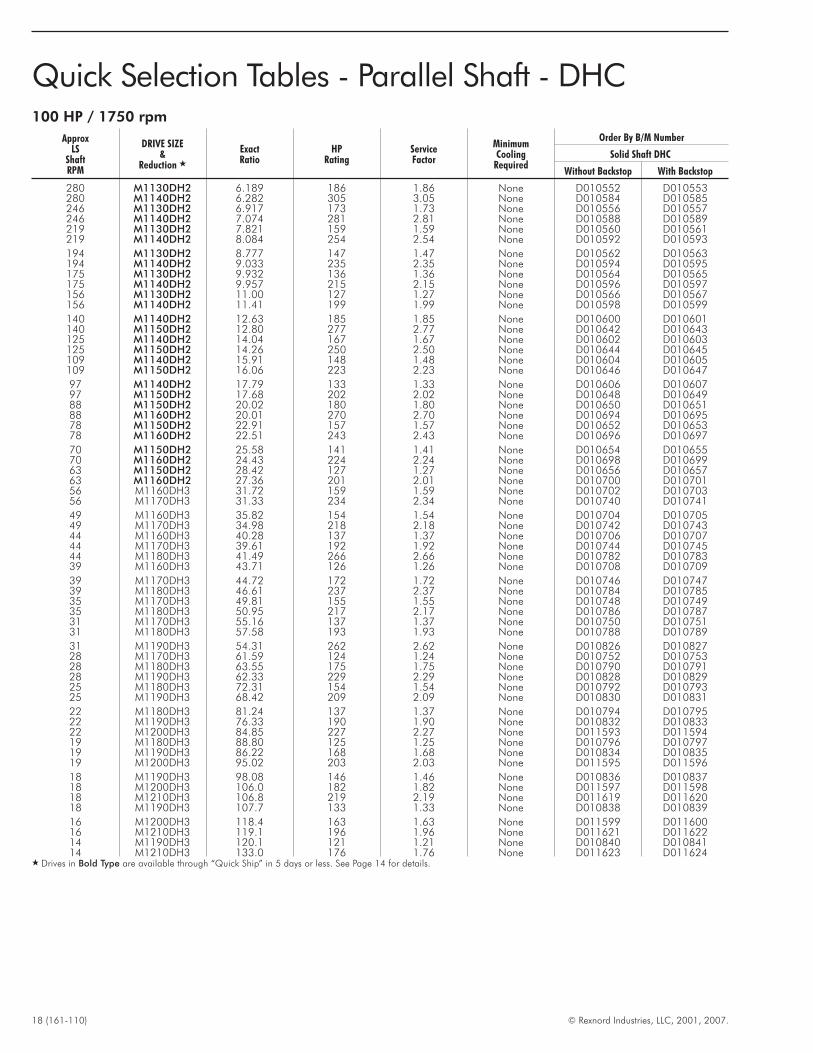
Quick Selection Tables - Parallel Shaft - DHC100 HP / 1750 rpm
ApproxLS
ShaftRPM
DRIVE SIZE&
Reduction �
ExactRatio
HPRating
ServiceFactor
MinimumCooling
Required
Order By B/M Number
Solid Shaft DHC
Without Backstop With Backstop
280 M1130DH2 6.189 186 1.86 None D010552 D010553280 M1140DH2 6.282 305 3.05 None D010584 D010585246 M1130DH2 6.917 173 1.73 None D010556 D010557246 M1140DH2 7.074 281 2.81 None D010588 D010589219 M1130DH2 7.821 159 1.59 None D010560 D010561219 M1140DH2 8.084 254 2.54 None D010592 D010593
194 M1130DH2 8.777 147 1.47 None D010562 D010563194 M1140DH2 9.033 235 2.35 None D010594 D010595175 M1130DH2 9.932 136 1.36 None D010564 D010565175 M1140DH2 9.957 215 2.15 None D010596 D010597156 M1130DH2 11.00 127 1.27 None D010566 D010567156 M1140DH2 11.41 199 1.99 None D010598 D010599
140 M1140DH2 12.63 185 1.85 None D010600 D010601140 M1150DH2 12.80 277 2.77 None D010642 D010643125 M1140DH2 14.04 167 1.67 None D010602 D010603125 M1150DH2 14.26 250 2.50 None D010644 D010645109 M1140DH2 15.91 148 1.48 None D010604 D010605109 M1150DH2 16.06 223 2.23 None D010646 D010647
97 M1140DH2 17.79 133 1.33 None D010606 D01060797 M1150DH2 17.68 202 2.02 None D010648 D01064988 M1150DH2 20.02 180 1.80 None D010650 D01065188 M1160DH2 20.01 270 2.70 None D010694 D01069578 M1150DH2 22.91 157 1.57 None D010652 D01065378 M1160DH2 22.51 243 2.43 None D010696 D010697
70 M1150DH2 25.58 141 1.41 None D010654 D01065570 M1160DH2 24.43 224 2.24 None D010698 D01069963 M1150DH2 28.42 127 1.27 None D010656 D01065763 M1160DH2 27.36 201 2.01 None D010700 D01070156 M1160DH3 31.72 159 1.59 None D010702 D01070356 M1170DH3 31.33 234 2.34 None D010740 D010741
49 M1160DH3 35.82 154 1.54 None D010704 D01070549 M1170DH3 34.98 218 2.18 None D010742 D01074344 M1160DH3 40.28 137 1.37 None D010706 D01070744 M1170DH3 39.61 192 1.92 None D010744 D01074544 M1180DH3 41.49 266 2.66 None D010782 D01078339 M1160DH3 43.71 126 1.26 None D010708 D010709
39 M1170DH3 44.72 172 1.72 None D010746 D01074739 M1180DH3 46.61 237 2.37 None D010784 D01078535 M1170DH3 49.81 155 1.55 None D010748 D01074935 M1180DH3 50.95 217 2.17 None D010786 D01078731 M1170DH3 55.16 137 1.37 None D010750 D01075131 M1180DH3 57.58 193 1.93 None D010788 D010789
31 M1190DH3 54.31 262 2.62 None D010826 D01082728 M1170DH3 61.59 124 1.24 None D010752 D01075328 M1180DH3 63.55 175 1.75 None D010790 D01079128 M1190DH3 62.33 229 2.29 None D010828 D01082925 M1180DH3 72.31 154 1.54 None D010792 D01079325 M1190DH3 68.42 209 2.09 None D010830 D010831
22 M1180DH3 81.24 137 1.37 None D010794 D01079522 M1190DH3 76.33 190 1.90 None D010832 D01083322 M1200DH3 84.85 227 2.27 None D011593 D01159419 M1180DH3 88.80 125 1.25 None D010796 D01079719 M1190DH3 86.22 168 1.68 None D010834 D01083519 M1200DH3 95.02 203 2.03 None D011595 D011596
18 M1190DH3 98.08 146 1.46 None D010836 D01083718 M1200DH3 106.0 182 1.82 None D011597 D01159818 M1210DH3 106.8 219 2.19 None D011619 D01162018 M1190DH3 107.7 133 1.33 None D010838 D010839
16 M1200DH3 118.4 163 1.63 None D011599 D01160016 M1210DH3 119.1 196 1.96 None D011621 D01162214 M1190DH3 120.1 121 1.21 None D010840 D01084114 M1210DH3 133.0 176 1.76 None D011623 D011624
� Drives in Bold Type are available through “Quick Ship” in 5 days or less. See Page 14 for details.
© Rexnord Industries, LLC, 2001, 2007. (161-110) 19
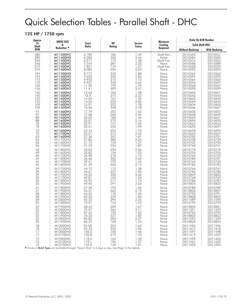
Quick Selection Tables - Parallel Shaft - DHC125 HP / 1750 rpm
ApproxLS
ShaftRPM
DRIVE SIZE&
Reduction �
ExactRatio
HPRating
ServiceFactor
MinimumCooling
Required
Order By B/M Number
Solid Shaft DHC
Without Backstop With Backstop
280 M1130DH2 6.189 186 1.49 Shaft Fan D010550 D010551280 M1140DH2 6.282 305 2.44 None D010584 D010585246 M1130DH2 6.917 173 1.38 Shaft Fan D010554 D010555246 M1140DH2 7.074 281 2.25 None D010588 D010589219 M1130DH2 7.821 159 1.27 Shaft Fan D010558 D010559219 M1140DH2 8.084 254 2.03 None D010592 D010593
194 M1130DH2 8.777 235 1.88 None D010562 D010563194 M1140DH2 9.033 355 2.84 None D010594 D010595175 M1130DH2 9.932 215 1.72 None D010564 D010565175 M1140DH2 9.957 330 2.64 None D010596 D010597156 M1130DH2 11.00 199 1.59 None D010566 D010567156 M1140DH2 11.41 309 2.47 None D010598 D010599
140 M1140DH2 12.63 185 1.48 None D010600 D010601140 M1150DH2 12.8 277 2.22 None D010642 D010643125 M1140DH2 14.04 167 1.34 None D010602 D010603125 M1150DH2 14.26 250 2.00 None D010644 D010645109 M1140DH2 15.91 223 1.78 None D010604 D010605109 M1150DH2 16.06 348 2.78 None D010646 D010647
97 M1140DH2 17.79 202 1.62 None D010606 D01060797 M1150DH2 17.68 306 2.45 None D010648 D01064988 M1150DH2 20.02 180 1.44 None D010650 D01065188 M1160DH2 20.01 270 2.16 None D010694 D01069578 M1150DH2 22.91 157 1.26 None D010652 D01065378 M1160DH2 22.51 243 1.94 None D010696 D010697
70 M1160DH2 24.43 224 1.79 None D010698 D01069970 M1170DH2 25.01 312 2.50 None D010656 D01065763 M1160DH2 27.36 201 1.61 None D010700 D01070163 M1170DH3 27.86 280 2.24 None D010738 D01073956 M1160DH3 31.72 159 1.27 None D010702 D01070356 M1170DH3 31.33 234 1.87 None D010740 D010741
56 M1180DH3 33.03 333 2.66 None D010778 D01077949 M1160DH3 35.82 154 1.23 None D010704 D01070549 M1170DH3 34.98 218 1.74 None D010742 D01074249 M1180DH3 36.46 302 2.42 None D010780 D01078144 M1170DH3 39.61 192 1.54 None D010744 D01074544 M1180DH3 41.49 266 2.13 None D010782 D010783
39 M1170DH3 44.72 172 1.38 None D010746 D01074739 M1180DH3 46.61 237 1.90 None D010784 D01078539 M1190DH3 44.23 328 2.62 None D010849 D01085035 M1170DH3 49.81 155 1.24 None D010748 D01074935 M1180DH3 50.95 217 1.74 None D010786 D01078735 M1190DH3 49.96 291 2.33 None D010824 D010825
31 M1180DH3 57.58 193 1.54 None D010788 D01078931 M1190DH3 54.31 262 2.10 None D010826 D01082728 M1180DH3 63.55 175 1.40 None D010790 D01079128 M1190DH3 62.33 229 1.83 None D010828 D01082928 M1200DH3 65.32 294 2.35 None D011589 D01159025 M1180DH3 72.31 154 1.23 None D010792 D010793
25 M1190DH3 68.42 209 1.67 None D010830 D01083125 M1200DH3 72.97 264 2.11 None D011591 D01159222 M1180DH3 81.24 190 1.52 None D010794 D01079522 M1190DH3 76.33 227 1.82 None D010832 D01083322 M1200DH3 84.85 284 2.27 None D011593 D01159420 M1190DH3 86.22 168 1.34 None D010834 D010834
18 M1200DH3 95.02 203 1.62 None D011595 D01159618 M1210DH3 95.33 245 1.96 None D011617 D01161817 M1200DH3 106.0 182 1.46 None D011597 D01159817 M1210DH3 106.8 219 1.75 None D011619 D011620
15 M1200DH3 118.4 163 1.30 None D011599 D01160015 M1210DH3 119.1 196 1.57 None D011621 D01162213 M1210DH3 133.0 176 1.41 None D011623 D011624
� Drives in Bold Type are available through “Quick Ship” in 5 days or less. See Page 14 for details.
20 (161-110) © Rexnord Industries, LLC, 2001, 2007.
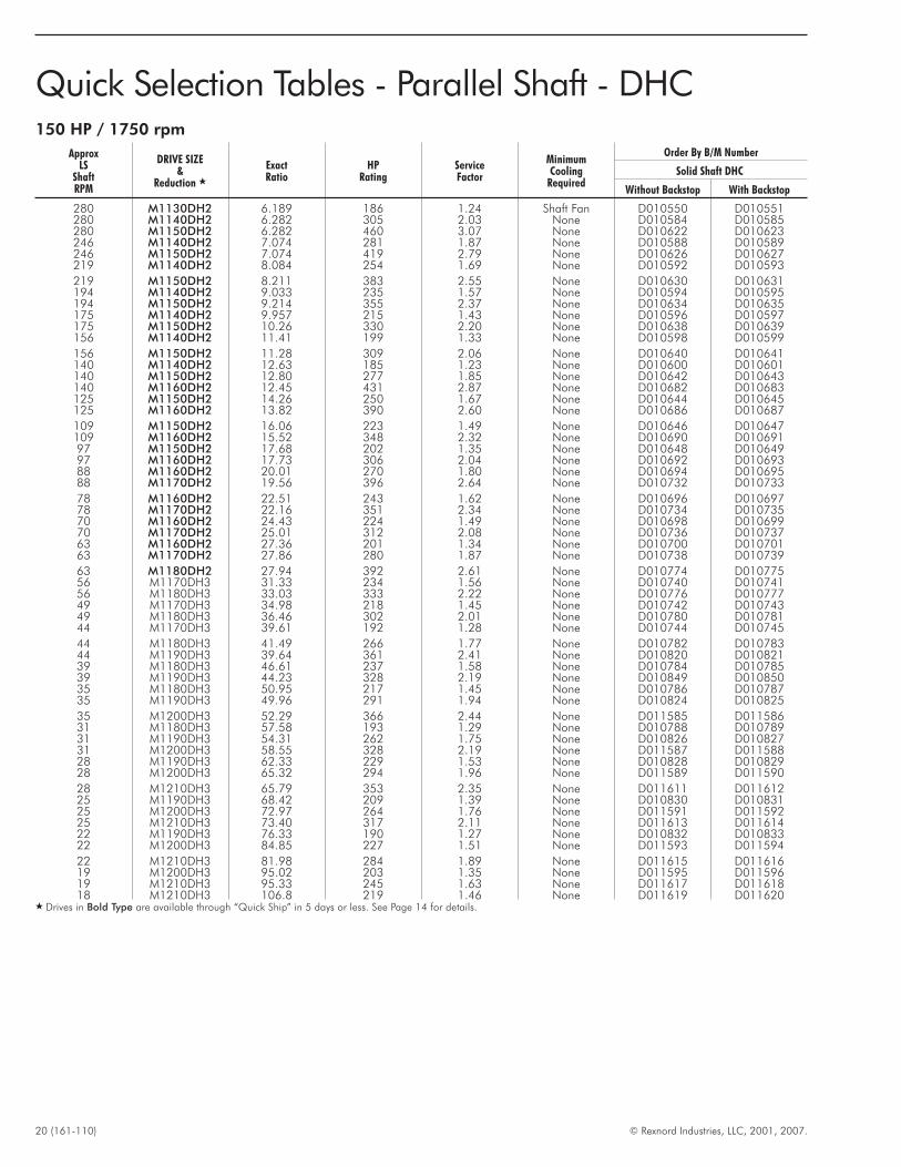
Quick Selection Tables - Parallel Shaft - DHC150 HP / 1750 rpm
ApproxLS
ShaftRPM
DRIVE SIZE&
Reduction �
ExactRatio
HPRating
ServiceFactor
MinimumCooling
Required
Order By B/M Number
Solid Shaft DHC
Without Backstop With Backstop
280 M1130DH2 6.189 186 1.24 Shaft Fan D010550 D010551280 M1140DH2 6.282 305 2.03 None D010584 D010585280 M1150DH2 6.282 460 3.07 None D010622 D010623246 M1140DH2 7.074 281 1.87 None D010588 D010589246 M1150DH2 7.074 419 2.79 None D010626 D010627219 M1140DH2 8.084 254 1.69 None D010592 D010593
219 M1150DH2 8.211 383 2.55 None D010630 D010631194 M1140DH2 9.033 235 1.57 None D010594 D010595194 M1150DH2 9.214 355 2.37 None D010634 D010635175 M1140DH2 9.957 215 1.43 None D010596 D010597175 M1150DH2 10.26 330 2.20 None D010638 D010639156 M1140DH2 11.41 199 1.33 None D010598 D010599
156 M1150DH2 11.28 309 2.06 None D010640 D010641140 M1140DH2 12.63 185 1.23 None D010600 D010601140 M1150DH2 12.80 277 1.85 None D010642 D010643140 M1160DH2 12.45 431 2.87 None D010682 D010683125 M1150DH2 14.26 250 1.67 None D010644 D010645125 M1160DH2 13.82 390 2.60 None D010686 D010687
109 M1150DH2 16.06 223 1.49 None D010646 D010647109 M1160DH2 15.52 348 2.32 None D010690 D01069197 M1150DH2 17.68 202 1.35 None D010648 D01064997 M1160DH2 17.73 306 2.04 None D010692 D01069388 M1160DH2 20.01 270 1.80 None D010694 D01069588 M1170DH2 19.56 396 2.64 None D010732 D010733
78 M1160DH2 22.51 243 1.62 None D010696 D01069778 M1170DH2 22.16 351 2.34 None D010734 D01073570 M1160DH2 24.43 224 1.49 None D010698 D01069970 M1170DH2 25.01 312 2.08 None D010736 D01073763 M1160DH2 27.36 201 1.34 None D010700 D01070163 M1170DH2 27.86 280 1.87 None D010738 D010739
63 M1180DH2 27.94 392 2.61 None D010774 D01077556 M1170DH3 31.33 234 1.56 None D010740 D01074156 M1180DH3 33.03 333 2.22 None D010776 D01077749 M1170DH3 34.98 218 1.45 None D010742 D01074349 M1180DH3 36.46 302 2.01 None D010780 D01078144 M1170DH3 39.61 192 1.28 None D010744 D010745
44 M1180DH3 41.49 266 1.77 None D010782 D01078344 M1190DH3 39.64 361 2.41 None D010820 D01082139 M1180DH3 46.61 237 1.58 None D010784 D01078539 M1190DH3 44.23 328 2.19 None D010849 D01085035 M1180DH3 50.95 217 1.45 None D010786 D01078735 M1190DH3 49.96 291 1.94 None D010824 D010825
35 M1200DH3 52.29 366 2.44 None D011585 D01158631 M1180DH3 57.58 193 1.29 None D010788 D01078931 M1190DH3 54.31 262 1.75 None D010826 D01082731 M1200DH3 58.55 328 2.19 None D011587 D01158828 M1190DH3 62.33 229 1.53 None D010828 D01082928 M1200DH3 65.32 294 1.96 None D011589 D011590
28 M1210DH3 65.79 353 2.35 None D011611 D01161225 M1190DH3 68.42 209 1.39 None D010830 D01083125 M1200DH3 72.97 264 1.76 None D011591 D01159225 M1210DH3 73.40 317 2.11 None D011613 D01161422 M1190DH3 76.33 190 1.27 None D010832 D01083322 M1200DH3 84.85 227 1.51 None D011593 D011594
22 M1210DH3 81.98 284 1.89 None D011615 D01161619 M1200DH3 95.02 203 1.35 None D011595 D01159619 M1210DH3 95.33 245 1.63 None D011617 D01161818 M1210DH3 106.8 219 1.46 None D011619 D011620
� Drives in Bold Type are available through “Quick Ship” in 5 days or less. See Page 14 for details.
© Rexnord Industries, LLC, 2001, 2007. (161-110) 21
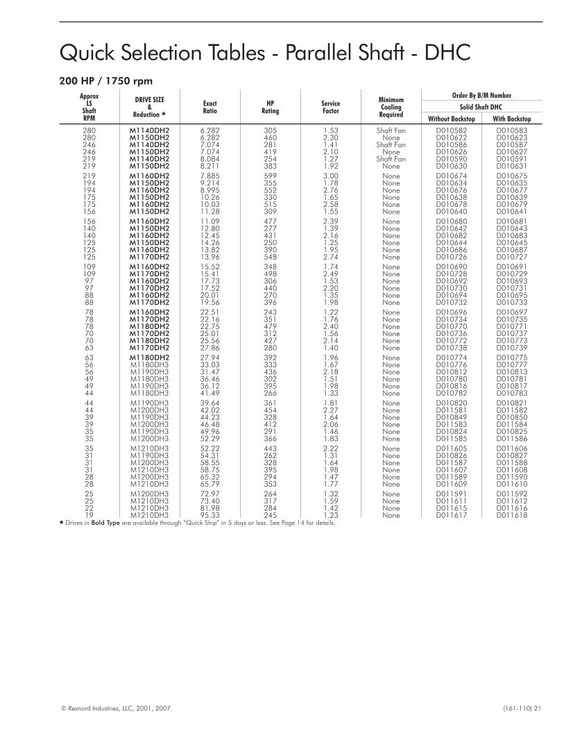
Quick Selection Tables - Parallel Shaft - DHC200 HP / 1750 rpm
ApproxLS
ShaftRPM
DRIVE SIZE&
Reduction �
ExactRatio
HPRating
ServiceFactor
MinimumCooling
Required
Order By B/M Number
Solid Shaft DHC
Without Backstop With Backstop
280 M1140DH2 6.282 305 1.53 Shaft Fan D010582 D010583280 M1150DH2 6.282 460 2.30 None D010622 D010623246 M1140DH2 7.074 281 1.41 Shaft Fan D010586 D010587246 M1150DH2 7.074 419 2.10 None D010626 D010627219 M1140DH2 8.084 254 1.27 Shaft Fan D010590 D010591219 M1150DH2 8.211 383 1.92 None D010630 D010631
219 M1160DH2 7.885 599 3.00 None D010674 D010675194 M1150DH2 9.214 355 1.78 None D010634 D010635194 M1160DH2 8.995 552 2.76 None D010676 D010677175 M1150DH2 10.26 330 1.65 None D010638 D010639175 M1160DH2 10.03 515 2.58 None D010678 D010679156 M1150DH2 11.28 309 1.55 None D010640 D010641
156 M1160DH2 11.09 477 2.39 None D010680 D010681140 M1150DH2 12.80 277 1.39 None D010642 D010643140 M1160DH2 12.45 431 2.16 None D010682 D010683125 M1150DH2 14.26 250 1.25 None D010644 D010645125 M1160DH2 13.82 390 1.95 None D010686 D010687125 M1170DH2 13.96 548 2.74 None D010726 D010727
109 M1160DH2 15.52 348 1.74 None D010690 D010691109 M1170DH2 15.41 498 2.49 None D010728 D01072997 M1160DH2 17.73 306 1.53 None D010692 D01069397 M1170DH2 17.52 440 2.20 None D010730 D01073188 M1160DH2 20.01 270 1.35 None D010694 D01069588 M1170DH2 19.56 396 1.98 None D010732 D010733
78 M1160DH2 22.51 243 1.22 None D010696 D01069778 M1170DH2 22.16 351 1.76 None D010734 D01073578 M1180DH2 22.75 479 2.40 None D010770 D01077170 M1170DH2 25.01 312 1.56 None D010736 D01073770 M1180DH2 25.56 427 2.14 None D010772 D01077363 M1170DH2 27.86 280 1.40 None D010738 D010739
63 M1180DH2 27.94 392 1.96 None D010774 D01077556 M1180DH3 33.03 333 1.67 None D010776 D01077756 M1190DH3 31.47 436 2.18 None D010812 D01081349 M1180DH3 36.46 302 1.51 None D010780 D01078149 M1190DH3 36.12 395 1.98 None D010816 D01081744 M1180DH3 41.49 266 1.33 None D010782 D010783
44 M1190DH3 39.64 361 1.81 None D010820 D01082144 M1200DH3 42.02 454 2.27 None D011581 D01158239 M1190DH3 44.23 328 1.64 None D010849 D01085039 M1200DH3 46.48 412 2.06 None D011583 D01158435 M1190DH3 49.96 291 1.46 None D010824 D01082535 M1200DH3 52.29 366 1.83 None D011585 D011586
35 M1210DH3 52.22 443 2.22 None D011605 D01160631 M1190DH3 54.31 262 1.31 None D010826 D01082731 M1200DH3 58.55 328 1.64 None D011587 D01158831 M1210DH3 58.75 395 1.98 None D011607 D01160828 M1200DH3 65.32 294 1.47 None D011589 D01159028 M1210DH3 65.79 353 1.77 None D011609 D011610
25 M1200DH3 72.97 264 1.32 None D011591 D01159225 M1210DH3 73.40 317 1.59 None D011611 D01161222 M1210DH3 81.98 284 1.42 None D011615 D01161619 M1210DH3 95.33 245 1.23 None D011617 D011618
� Drives in Bold Type are available through “Quick Ship” in 5 days or less. See Page 14 for details.
22 (161-110) © Rexnord Industries, LLC, 2001, 2007.
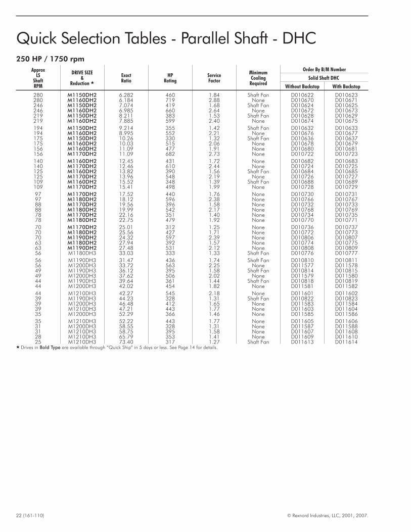
Quick Selection Tables - Parallel Shaft - DHC250 HP / 1750 rpm
ApproxLS
ShaftRPM
DRIVE SIZE&
Reduction �
ExactRatio
HPRating
ServiceFactor
MinimumCooling
Required
Order By B/M Number
Solid Shaft DHC
Without Backstop With Backstop
280 M1150DH2 6.282 460 1.84 Shaft Fan D010622 D010623280 M1160DH2 6.184 719 2.88 None D010670 D010671246 M1150DH2 7.074 419 1.68 Shaft Fan D010624 D010625246 M1160DH2 6.985 660 2.64 None D010672 D010673219 M1150DH2 8.211 383 1.53 Shaft Fan D010628 D010629219 M1160DH2 7.885 599 2.40 None D010674 D010675
194 M1150DH2 9.214 355 1.42 Shaft Fan D010632 D010633194 M1160DH2 8.995 552 2.21 None D010676 D010677175 M1150DH2 10.26 330 1.32 Shaft Fan D010636 D010637175 M1160DH2 10.03 515 2.06 None D010678 D010679156 M1160DH2 11.09 477 1.91 None D010680 D010681156 M1170DH2 11.09 682 2.73 None D010722 D010723
140 M1160DH2 12.45 431 1.72 None D010682 D010683140 M1170DH2 12.46 610 2.44 None D010724 D010725125 M1160DH2 13.82 390 1.56 Shaft Fan D010684 D010685125 M1170DH2 13.96 548 2.19 None D010726 D010727109 M1160DH2 15.52 348 1.39 Shaft Fan D010688 D010689109 M1170DH2 15.41 498 1.99 None D010728 D010729
97 M1170DH2 17.52 440 1.76 None D010730 D01073197 M1180DH2 18.12 596 2.38 None D010766 D01076788 M1170DH2 19.56 396 1.58 None D010732 D01073388 M1180DH2 19.99 542 2.17 None D010768 D01076978 M1170DH2 22.16 351 1.40 None D010734 D01073578 M1180DH2 22.75 479 1.92 None D010770 D010771
70 M1170DH2 25.01 312 1.25 None D010736 D01073770 M1180DH2 25.56 427 1.71 None D010772 D01077370 M1190DH2 24.32 597 2.39 None D010806 D01080763 M1180DH2 27.94 392 1.57 None D010774 D01077563 M1190DH2 27.48 531 2.12 None D010808 D01080956 M1180DH3 33.03 333 1.33 Shaft Fan D010776 D010777
56 M1190DH3 31.47 436 1.74 Shaft Fan D010810 D01081156 M1200DH3 33.72 563 2.25 None D011577 D01157849 M1190DH3 36.12 395 1.58 Shaft Fan D010814 D01081549 M1200DH3 37.62 506 2.02 None D011579 D01158044 M1190DH3 39.64 361 1.44 Shaft Fan D010818 D01081944 M1200DH3 42.02 454 1.82 None D011581 D011582
44 M1210DH3 42.27 545 2.18 None D011601 D01160239 M1190DH3 44.23 328 1.31 Shaft Fan D010822 D01082339 M1200DH3 46.48 412 1.65 None D011583 D01158439 M1210DH3 47.21 443 1.77 None D011603 D01160435 M1200DH3 52.29 366 1.46 None D011585 D011586
35 M1210DH3 52.22 443 1.77 None D011605 D01160631 M1200DH3 58.55 328 1.31 None D011587 D01158831 M1210DH3 58.75 395 1.58 None D011607 D01160828 M1210DH3 65.79 353 1.41 None D011609 D01161025 M1210DH3 73.40 317 1.27 Shaft Fan D011613 D011614
� Drives in Bold Type are available through “Quick Ship” in 5 days or less. See Page 14 for details.
© Rexnord Industries, LLC, 2001, 2007. (161-110) 23
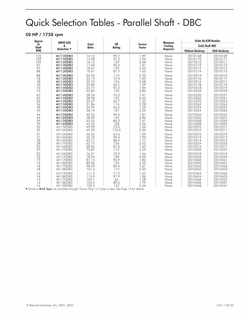
Quick Selection Tables - Parallel Shaft - DBC50 HP / 1750 rpm
ApproxLS
ShaftRPM
DRIVE SIZE&
Reduction �
ExactRatio
HPRating
ServiceFactor
MinimumCooling
Required
Order By B/M Number
Solid Shaft DBC
Without Backstop With Backstop
125 M1130DB3 14.12 99.7 1.99 None D010168 D010169109 M1130DB3 15.98 97.2 1.94 None D010170 D010171109 M1140DB3 16.12 129 2.58 None D010210 D01021197 M1130DB3 17.69 90.4 1.81 None D010172 D01017397 M1140DB3 18.47 122 2.44 None D010212 D01021388 M1130DB3 19.61 81.7 1.63 None D010174 D010175
88 M1140DB3 20.45 116 2.32 None D010214 D01021578 M1130DB3 22.19 72.4 1.45 None D010176 D01017778 M1140DB3 22.72 104 2.08 None D010216 D01021770 M1130DB3 24.89 64.7 1.29 None D010178 D01017970 M1140DB3 25.75 92.2 1.84 None D010218 D01021970 M1150DB3 25.84 140 2.80 None D010258 D010259
63 M1140DB3 28.34 70.3 1.41 None D010220 D01022163 M1150DB3 28.98 125 2.50 None D010260 D01026156 M1140DB3 32.47 66.7 1.33 None D010222 D01022356 M1150DB3 31.86 114 2.28 None D010262 D01026349 M1140DB3 35.95 64.5 1.29 None D010224 D01022549 M1150DB3 36.14 101 2.02 None D010264 D010265
44 M1150DB3 40.25 90.4 1.81 None D010266 D01026744 M1160DB3 38.49 143 2.86 None D010306 D01030739 M1150DB3 45.35 80.3 1.61 None D010268 D01026939 M1160DB3 43.25 128 2.56 None D010308 D01030935 M1150DB3 49.93 73.0 1.46 None D010270 D01027135 M1160DB3 49.39 110.0 2.20 None D010310 D010311
31 M1150DB3 56.52 64.6 1.29 None D010272 D01027331 M1160DB3 55.75 99.4 1.99 None D010312 D01031328 M1160DB3 62.71 88.5 1.77 None D010314 D01031528 M1170DB3 62.77 126 2.52 None D010354 D01035525 M1160DB3 68.05 81.6 1.63 None D010316 D01031725 M1170DB3 70.87 112 2.24 None D010356 D010357
22 M1160DB3 76.21 72.9 1.46 None D010318 D01031922 M1170DB3 78.94 100 2.00 None D010358 D01035919 M1170DB3 87.15 90.9 1.82 None D010360 D01036119 M1180DB3 89.06 125 2.50 None D010400 D01040118 M1170DB3 98.69 80.4 1.61 None D010362 D01036318 M1180DB3 101.3 110 2.20 None D010402 D010403
16 M1170DB3 111.4 71.2 1.42 None D010364 D01036516 M1180DB3 113.9 97.9 1.96 None D010404 D01040514 M1170DB3 124.1 64 1.28 None D010366 D01036714 M1180DB3 124.5 89.6 1.79 None D010406 D01040714 M1190DB3 122.4 122 2.44 None D010446 D010447
� Drives in Bold Type are available through “Quick Ship” in 5 days or less. See Page 14 for details.

24 (161-110) © Rexnord Industries, LLC, 2001, 2007.
Quick Selection Tables - Parallel Shaft - DBC60 HP / 1750 rpm
ApproxLS
ShaftRPM
DRIVE SIZE&
Reduction �
ExactRatio
HPRating
ServiceFactor
MinimumCooling
Required
Order By B/M Number
Solid Shaft DBC
Without Backstop With Backstop
125 M1130DB3 14.12 99.7 1.66 None D010168 D010169125 M1140DB3 14.63 137 2.28 None D010208 D010209109 M1130DB3 15.98 97.2 1.62 None D010170 D010171109 M1140DB3 16.12 129 2.15 None D010210 D01021197 M1130DB3 17.69 90.4 1.51 None D010172 D01017397 M1140DB3 18.47 122 2.03 None D010212 D010213
88 M1130DB3 19.61 81.7 1.36 None D010174 D01017588 M1140DB3 20.45 116 1.93 None D010214 D01021578 M1140DB3 22.72 104 1.73 None D010216 D01021778 M1150DB3 22.93 157 2.62 None D010256 D01025770 M1140DB3 25.75 92.2 1.54 None D010218 D01021970 M1150DB3 25.84 140 2.33 None D010258 D010259
63 M1150DB3 28.98 125 2.08 None D010260 D01026156 M1150DB3 31.86 114 1.90 None D010262 D01026356 M1160DB3 30.89 173 2.88 None D010302 D01030349 M1150DB3 36.14 101 1.68 None D010264 D01026549 M1160DB3 34.68 159 2.65 None D010304 D01030544 M1150DB3 40.25 90.4 1.51 None D010266 D010267
44 M1160DB3 38.49 143 2.38 None D010306 D01030739 M1150DB3 45.35 80.3 1.34 None D010268 D01026939 M1160DB3 43.25 128 2.13 None D010308 D01030935 M1160DB3 49.39 110 1.83 None D010310 D01031135 M1170DB3 49.65 159 2.65 None D010350 D01035131 M1160DB3 55.75 99.4 1.66 None D010312 D010313
31 M1170DB3 55.43 142 2.37 None D010352 D01035328 M1160DB3 62.71 88.5 1.48 None D010314 D01031528 M1170DB3 62.77 126 2.10 None D010354 D01035525 M1160DB3 68.05 81.6 1.36 None D010316 D01031725 M1170DB3 70.87 112 1.87 None D010356 D01035725 M1180DB3 72.17 154 2.57 None D010396 D010397
22 M1170DB3 78.94 100 1.67 None D010358 D01035922 M1180DB3 78.89 141 2.35 None D010398 D01039919 M1170DB3 87.15 90.9 1.52 None D010360 D01036119 M1180DB3 89.06 125 2.08 None D010400 D01040118 M1170DB3 98.69 80.4 1.34 None D010362 D01036318 M1180DB3 101.3 110 1.83 None D010402 D010403
18 M1190DB3 97.13 153 2.55 None D010442 D01044316 M1180DB3 113.9 97.9 1.63 None D010404 D01040516 M1190DB3 108.4 137 2.28 None D010444 D01044514 M1180DB3 124.5 89.6 1.49 None D010406 D01040714 M1190DB3 122.4 122 2.03 None D010446 D010447
� Drives in Bold Type are available through “Quick Ship” in 5 days or less. See Page 14 for details.
© Rexnord Industries, LLC, 2001, 2007. (161-110) 25
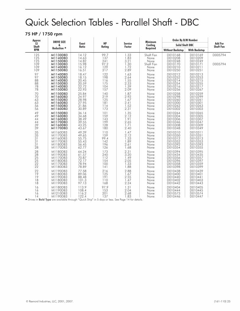
Quick Selection Tables - Parallel Shaft - DBC75 HP / 1750 rpm
ApproxLS
ShaftRPM
DRIVE SIZE&
Reduction �
ExactRatio
HPRating
ServiceFactor
MinimumCooling
Required
Order By B/M NumberAdd For
Shaft FanSolid Shaft DBC
Without Backstop With Backstop
125 M1130DB3 14.12 99.7 1.33 Shaft Fan D010168 D010169 D005794125 M1140DB3 14.63 137 1.83 None D010208 D010209125 M1150DB3 14.82 241 3.21 None D010248 D010249109 M1130DB3 15.98 97.2 1.30 Shaft Fan D010170 D010171 D005794109 M1140DB3 16.12 129 1.72 None D010210 D010211109 M1150DB3 16.51 217 2.89 None D010250 D010251
97 M1140DB3 18.47 122 1.63 None D010212 D01021397 M1150DB3 18.15 198 2.64 None D010252 D01025388 M1140DB3 20.45 116 1.55 None D010214 D01021588 M1150DB3 20.59 175 2.33 None D010254 D01025578 M1140DB3 22.72 104 1.39 None D010216 D01021778 M1150DB3 22.93 157 2.09 None D010256 D010267
70 M1150DB3 25.84 140 1.87 None D010258 D01025970 M1160DB3 24.97 219 2.92 None D010298 D01029963 M1150DB3 28.98 125 1.67 None D010260 D01026163 M1160DB3 27.95 181 2.41 None D010300 D01030156 M1150DB3 31.86 114 1.52 None D010262 D01026356 M1160DB3 30.89 173 2.31 None D010302 D010303
49 M1150DB3 36.14 101 1.35 None D010264 D01026549 M1160DB3 34.68 159 2.12 None D010304 D01030544 M1160DB3 38.49 143 1.91 None D010306 D01030744 M1170DB3 39.55 199 2.65 None D010346 D01034739 M1160DB3 43.25 128 1.71 None D010308 D01030939 M1170DB3 43.67 180 2.40 None D010348 D010349
35 M1160DB3 49.39 110 1.47 None D010310 D01031135 M1170DB3 49.65 159 2.12 None D010350 D01035131 M1160DB3 55.75 99.4 1.33 None D010312 D01031331 M1170DB3 55.43 142 1.89 None D010352 D01035331 M1180DB3 56.45 196 2.61 None D010392 D01039328 M1170DB3 62.77 126 1.68 None D010354 D010355
28 M1180DB3 64.24 173 2.31 None D010394 D01039528 M1190DB3 61.57 240 3.20 None D010434 D01043525 M1170DB3 70.87 112 1.49 None D010356 D01035725 M1180DB3 72.17 154 2.05 None D010396 D01039722 M1170DB3 78.94 100 1.33 None D010358 D01035922 M1180DB3 78.89 141 1.88 None D010398 D010399
22 M1190DB3 77.58 216 2.88 None D010438 D01043919 M1180DB3 89.06 125 1.67 None D010400 D01040119 M1190DB3 88.48 191 2.55 None D010440 D01044118 M1180DB3 101.3 110 1.47 None D010402 D01040318 M1190DB3 97.13 168 2.24 None D010442 D010443
16 M1180DB3 113.9 97.9 1.31 None D010404 D01040516 M1190DB3 108.4 153 2.04 None D010444 D01044516 M1210DB3 116.2 201 2.68 None D010573 D01057414 M1190DB3 122.4 137 1.83 None D010446 D010447
� Drives in Bold Type are available through “Quick Ship” in 5 days or less. See Page 14 for details.
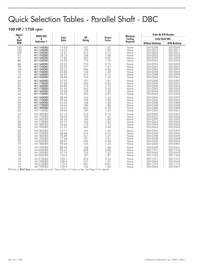
26 (161-110) © Rexnord Industries, LLC, 2001, 2007.
Quick Selection Tables - Parallel Shaft - DBC100 HP / 1750 rpm
ApproxLS
ShaftRPM
DRIVE SIZE&
Reduction �
ExactRatio
HPRating
ServiceFactor
MinimumCooling
Required
Order By B/M Number
Solid Shaft DBC
Without Backstop With Backstop
125 M1140DB3 14.63 137 1.37 None D010208 D010209109 M1140DB3 16.12 129 1.29 None D010210 D010211109 M1150DB3 16.51 217 2.17 None D010250 D01025197 M1150DB3 18.15 198 1.98 None D010252 D01025397 M1160DB3 17.84 305 3.05 None D010292 D01029388 M1150DB3 20.59 175 1.75 None D010254 D010255
88 M1160DB3 20.03 270 2.70 None D010294 D01029578 M1150DB3 22.93 157 1.57 None D010256 D01025778 M1160DB3 22.23 246 2.46 None D010296 D01029770 M1150DB3 25.84 140 1.40 None D010258 D01025970 M1160DB3 24.97 219 2.19 None D010298 D01029963 M1150DB3 28.98 125 1.25 None D010260 D010261
63 M1160DB3 27.95 181 1.81 None D010300 D01030163 M1170DB3 27.60 242 2.42 None D010340 D01034156 M1160DB3 30.89 173 1.73 None D010302 D01030356 M1170DB3 31.42 242 2.42 None D010342 D01034349 M1160DB3 34.68 159 1.59 None D010304 D01030549 M1170DB3 35.30 222 2.22 None D010344 D010345
44 M1160DB3 38.49 143 1.43 None D010306 D01030744 M1170DB3 39.55 199 1.99 None D010346 D01034739 M1160DB3 43.25 128 1.28 None D010308 D01030939 M1170DB3 43.67 180 1.80 None D010348 D01034939 M1180DB3 45.57 242 2.42 None D010388 D01038935 M1170DB3 49.65 159 1.59 None D010350 D010351
35 M1180DB3 51.15 216 2.16 None D010390 D01039131 M1170DB3 55.43 142 1.42 None D010352 D01035331 M1180DB3 56.45 196 1.96 None D010392 D01039328 M1170DB3 62.77 126 1.26 None D010354 D01035528 M1180DB3 64.24 173 1.73 None D010394 D01039528 M1190DB3 61.57 240 2.40 None D010434 D010435
25 M1180DB3 72.17 154 1.54 None D010396 D01039725 M1190DB3 68.68 216 2.16 None D010436 D01043722 M1180DB3 78.89 141 1.41 None D010398 D01039922 M1190DB3 77.58 191 1.91 None D010438 D01043922 M1200DB3 83.01 232 2.32 None D010549 D01055019 M1180DB3 89.06 125 1.25 None D010400 D010401
19 M1190DB3 88.48 168 1.68 None D010440 D01044119 M1200DB3 92.61 208 2.08 None D011551 D01155218 M1190DB3 97.13 153 1.53 None D010442 D01044318 M1200DB3 103.4 187 1.87 None D011553 D011554
18 M1210DB3 104.1 224 2.24 None D011571 D01157216 M1190DB3 108.4 137 1.37 None D010444 D01044516 M1210DB3 116.2 201 2.01 None D011573 D01157414 M1190DB3 122.4 122 1.22 None D010446 D010447
� Drives in Bold Type are available through “Quick Ship” in 5 days or less. See Page 14 for details.
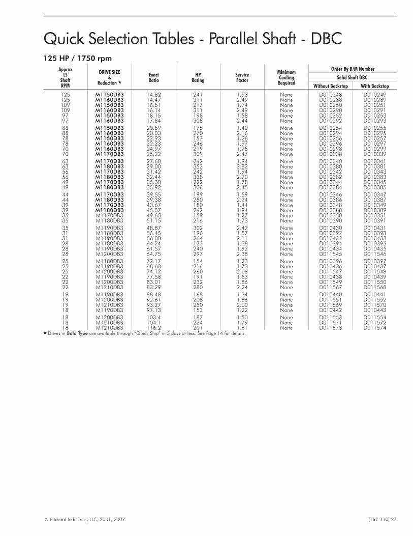
© Rexnord Industries, LLC, 2001, 2007. (161-110) 27
Quick Selection Tables - Parallel Shaft - DBC125 HP / 1750 rpm
ApproxLS
ShaftRPM
DRIVE SIZE&
Reduction �
ExactRatio
HPRating
ServiceFactor
MinimumCooling
Required
Order By B/M Number
Solid Shaft DBC
Without Backstop With Backstop
125 M1150DB3 14.82 241 1.93 None D010248 D010249125 M1160DB3 14.47 311 2.49 None D010288 D010289109 M1150DB3 16.51 217 1.74 None D010250 D010251109 M1160DB3 16.14 311 2.49 None D010290 D01029197 M1150DB3 18.15 198 1.58 None D010252 D01025397 M1160DB3 17.84 305 2.44 None D010292 D010293
88 M1150DB3 20.59 175 1.40 None D010254 D01025588 M1160DB3 20.03 270 2.16 None D010294 D01029578 M1150DB3 22.93 157 1.26 None D010256 D01025778 M1160DB3 22.23 246 1.97 None D010296 D01029770 M1160DB3 24.97 219 1.75 None D010298 D01029970 M1170DB3 25.22 309 2.47 None D010338 D010339
63 M1170DB3 27.60 242 1.94 None D010340 D01034163 M1180DB3 29.00 352 2.82 None D010380 D01038156 M1170DB3 31.42 242 1.94 None D010342 D01034356 M1180DB3 32.44 338 2.70 None D010382 D01038349 M1170DB3 35.30 222 1.78 None D010344 D01034549 M1180DB3 35.92 306 2.45 None D010384 D010385
44 M1170DB3 39.55 199 1.59 None D010346 D01034744 M1180DB3 39.38 280 2.24 None D010386 D01038739 M1170DB3 43.67 180 1.44 None D010348 D01034939 M1180DB3 45.57 242 1.94 None D010388 D01038935 M1170DB3 49.65 159 1.27 None D010350 D01035135 M1180DB3 51.15 216 1.73 None D010390 D010391
35 M1190DB3 48.87 302 2.42 None D010430 D01043131 M1180DB3 56.45 196 1.57 None D010392 D01039331 M1190DB3 56.08 264 2.11 None D010432 D01043328 M1180DB3 64.24 173 1.38 None D010394 D01039528 M1190DB3 61.57 240 1.92 None D010434 D01043528 M1200DB3 64.75 297 2.38 None D011545 D011546
25 M1180DB3 72.17 154 1.23 None D010396 D01039725 M1190DB3 68.68 216 1.73 None D010436 D01043725 M1200DB3 74.12 260 2.08 None D011547 D01154822 M1190DB3 77.58 191 1.53 None D010438 D01043922 M1200DB3 83.01 232 1.86 None D011549 D01155022 M1210DB3 83.29 280 2.24 None D011567 D011568
19 M1190DB3 88.48 168 1.34 None D010440 D01044119 M1200DB3 92.61 208 1.66 None D011551 D01155219 M1210DB3 93.27 250 2.00 None D011569 D01157018 M1190DB3 97.13 153 1.22 None D010442 D010443
18 M1200DB3 103.4 187 1.50 None D011553 D01155418 M1210DB3 104.1 224 1.79 None D011571 D01157216 M1210DB3 116.2 201 1.61 None D011573 D011574
� Drives in Bold Type are available through “Quick Ship” in 5 days or less. See Page 14 for details.
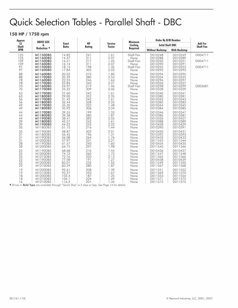
28 (161-110) © Rexnord Industries, LLC, 2001, 2007.
Quick Selection Tables - Parallel Shaft - DBC150 HP / 1750 rpm
ApproxLS
ShaftRPM
DRIVE SIZE&
Reduction �
ExactRatio
HPRating
ServiceFactor
MinimumCooling
Required
Order By B/M NumberAdd For
Shaft FanSolid Shaft DBC
Without Backstop With Backstop
125 M1150DB3 14.82 241 1.61 Shaft Fan D010248 D010249 D004711125 M1160DB3 14.47 311 2.07 None D010288 D010289109 M1150DB3 16.51 217 1.45 Shaft Fan D010250 D010251 D004711109 M1160DB3 16.14 311 2.07 None D010290 D01029197 M1150DB3 18.15 198 1.32 Shaft Fan D010252 D010253 D00471197 M1160DB3 17.84 305 2.03 None D010292 D010293
88 M1160DB3 20.03 270 1.80 None D010294 D01029588 M1170DB3 20.39 380 2.53 None D010334 D01033578 M1160DB3 22.23 246 1.64 None D010296 D01029778 M1170DB3 22.84 340 2.27 None D010336 D01033770 M1160DB3 24.97 219 1.46 Shaft Fan D010298 D010299 D00368170 M1170DB3 25.22 309 2.06 None D010338 D010339
63 M1170DB3 27.60 242 1.61 None D010340 D01034163 M1180DB3 29.00 352 2.35 None D010380 D01038156 M1170DB3 31.42 242 1.61 None D010342 D01034356 M1180DB3 32.44 338 2.25 None D010382 D01038349 M1170DB3 35.30 222 1.48 None D010344 D01034549 M1180DB3 35.92 306 2.04 None D010384 D010385
44 M1170DB3 39.55 199 1.33 None D010346 D01034744 M1180DB3 39.38 280 1.87 None D010386 D01038744 M1190DB3 38.41 383 2.55 None D010426 D01042739 M1180DB3 45.57 242 1.61 None D010388 D01038939 M1190DB3 44.22 333 2.22 None D010428 D01042935 M1180DB3 51.15 216 1.44 None D010390 D010391
35 M1190DB3 48.87 302 2.01 None D010430 D01043131 M1180DB3 56.45 196 1.31 None D010392 D01039331 M1190DB3 56.08 264 1.76 None D010432 D01043331 M1200DB3 57.97 331 2.21 None D011543 D01154428 M1190DB3 61.57 240 1.60 None D010434 D01043528 M1200DB3 64.75 297 1.98 None D011545 D011546
25 M1190DB3 68.68 216 1.44 None D010436 D01043725 M1200DB3 74.12 260 1.73 None D011547 D01154825 M1210DB3 72.76 320 2.13 None D011565 D01156622 M1190DB3 77.58 191 1.27 None D010438 D01043922 M1200DB3 83.01 232 1.55 None D011549 D01155022 M1210DB3 83.29 280 1.87 None D011567 D011568
19 M1200DB3 92.61 208 1.39 None D011551 D01155219 M1210DB3 93.27 250 1.67 None D011569 D01157018 M1200DB3 103.4 187 1.25 None D011553 D01155418 M1210DB3 104.1 224 1.49 None D011571 D01157216 M1210DB3 116.2 201 1.34 None D011573 D011574
� Drives in Bold Type are available through “Quick Ship” in 5 days or less. See Page 14 for details.
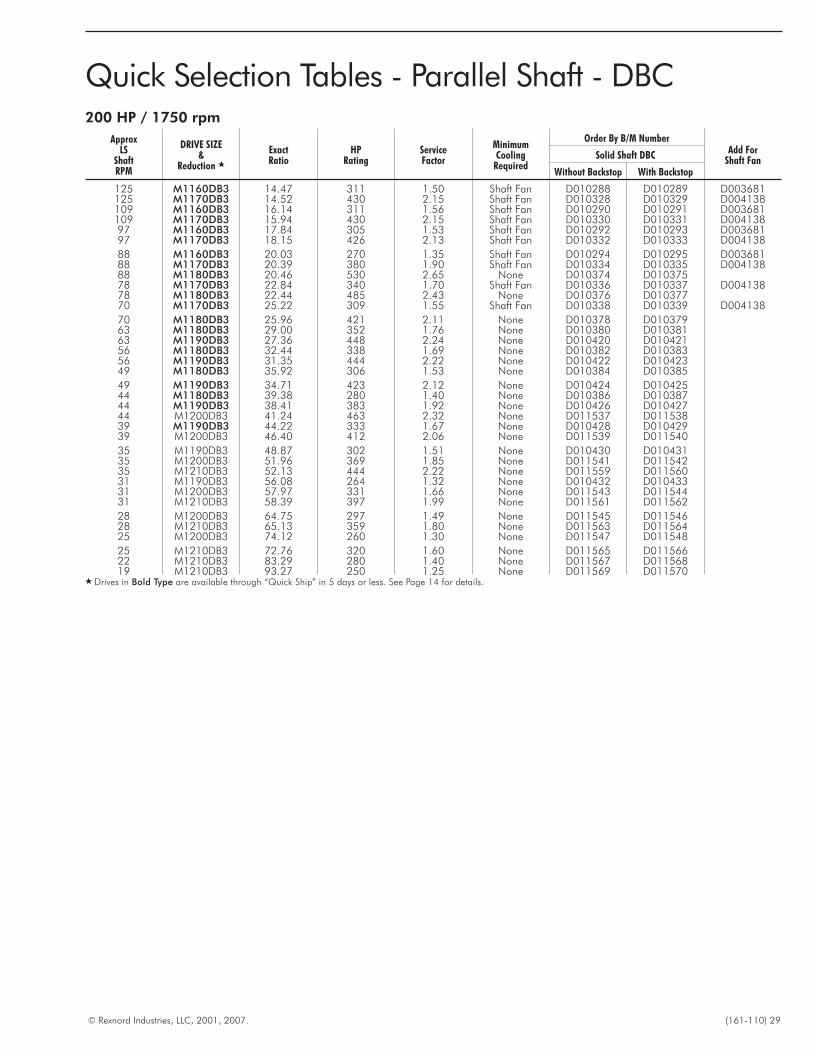
© Rexnord Industries, LLC, 2001, 2007. (161-110) 29
Quick Selection Tables - Parallel Shaft - DBC200 HP / 1750 rpm
ApproxLS
ShaftRPM
DRIVE SIZE&
Reduction �
ExactRatio
HPRating
ServiceFactor
MinimumCooling
Required
Order By B/M NumberAdd For
Shaft FanSolid Shaft DBC
Without Backstop With Backstop
125 M1160DB3 14.47 311 1.50 Shaft Fan D010288 D010289 D003681125 M1170DB3 14.52 430 2.15 Shaft Fan D010328 D010329 D004138109 M1160DB3 16.14 311 1.56 Shaft Fan D010290 D010291 D003681109 M1170DB3 15.94 430 2.15 Shaft Fan D010330 D010331 D00413897 M1160DB3 17.84 305 1.53 Shaft Fan D010292 D010293 D00368197 M1170DB3 18.15 426 2.13 Shaft Fan D010332 D010333 D004138
88 M1160DB3 20.03 270 1.35 Shaft Fan D010294 D010295 D00368188 M1170DB3 20.39 380 1.90 Shaft Fan D010334 D010335 D00413888 M1180DB3 20.46 530 2.65 None D010374 D01037578 M1170DB3 22.84 340 1.70 Shaft Fan D010336 D010337 D00413878 M1180DB3 22.44 485 2.43 None D010376 D01037770 M1170DB3 25.22 309 1.55 Shaft Fan D010338 D010339 D004138
70 M1180DB3 25.96 421 2.11 None D010378 D01037963 M1180DB3 29.00 352 1.76 None D010380 D01038163 M1190DB3 27.36 448 2.24 None D010420 D01042156 M1180DB3 32.44 338 1.69 None D010382 D01038356 M1190DB3 31.35 444 2.22 None D010422 D01042349 M1180DB3 35.92 306 1.53 None D010384 D010385
49 M1190DB3 34.71 423 2.12 None D010424 D01042544 M1180DB3 39.38 280 1.40 None D010386 D01038744 M1190DB3 38.41 383 1.92 None D010426 D01042744 M1200DB3 41.24 463 2.32 None D011537 D01153839 M1190DB3 44.22 333 1.67 None D010428 D01042939 M1200DB3 46.40 412 2.06 None D011539 D011540
35 M1190DB3 48.87 302 1.51 None D010430 D01043135 M1200DB3 51.96 369 1.85 None D011541 D01154235 M1210DB3 52.13 444 2.22 None D011559 D01156031 M1190DB3 56.08 264 1.32 None D010432 D01043331 M1200DB3 57.97 331 1.66 None D011543 D01154431 M1210DB3 58.39 397 1.99 None D011561 D011562
28 M1200DB3 64.75 297 1.49 None D011545 D01154628 M1210DB3 65.13 359 1.80 None D011563 D01156425 M1200DB3 74.12 260 1.30 None D011547 D011548
25 M1210DB3 72.76 320 1.60 None D011565 D01156622 M1210DB3 83.29 280 1.40 None D011567 D01156819 M1210DB3 93.27 250 1.25 None D011569 D011570
� Drives in Bold Type are available through “Quick Ship” in 5 days or less. See Page 14 for details.
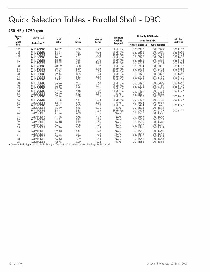
30 (161-110) © Rexnord Industries, LLC, 2001, 2007.
Quick Selection Tables - Parallel Shaft - DBC250 HP / 1750 rpm
ApproxLS
ShaftRPM
DRIVE SIZE&
Reduction �
ExactRatio
HPRating
ServiceFactor
MinimumCooling
Required
Order By B/M NumberAdd For
Shaft FanSolid Shaft DBC
Without Backstop With Backstop
125 M1170DB3 14.52 430 1.72 Shaft Fan D010328 D010329 D004138125 M1180DB3 14.41 687 2.75 Shaft Fan D010368 D010369 D004662109 M1170DB3 15.94 430 1.72 Shaft Fan D010330 D010331 D004138109 M1180DB3 16.52 651 2.60 Shaft Fan D010370 D010371 D00466297 M1170DB3 18.15 426 1.70 Shaft Fan D010332 D010333 D00413897 M1180DB3 18.48 585 2.34 Shaft Fan D010372 D010373 D004662
88 M1170DB3 20.39 380 1.52 Shaft Fan D010334 D010335 D00413888 M1180DB3 20.46 530 2.12 Shaft Fan D010374 D010375 D00466278 M1170DB3 22.84 340 1.36 Shaft Fan D010336 D010337 D00413878 M1180DB3 22.44 485 1.94 Shaft Fan D010376 D010377 D00466278 M1190DB3 21.88 662 2.65 Shaft Fan D010416 D010417 D00417770 M1170DB3 25.22 309 1.24 Shaft Fan D010338 D010339 D004138
70 M1180DB3 25.96 421 1.68 Shaft Fan D010378 D010379 D00466270 M1190DB3 25.19 577 2.31 Shaft Fan D010418 D010419 D00417763 M1180DB3 29.00 352 1.41 Shaft Fan D010380 D010381 D00466263 M1190DB3 27.36 448 1.79 Shaft Fan D010420 D010421 D00417763 M1200DB3 29.49 642 2.57 None D011531 D01153256 M1180DB3 32.44 338 1.35 Shaft Fan D010382 D010383 D004662
56 M1190DB3 31.35 444 1.78 Shaft Fan D010422 D010423 D00417756 M1200DB3 32.98 576 2.30 None D011533 D01153449 M1190DB3 34.71 423 1.69 Shaft Fan D010424 D010425 D00417749 M1200DB3 36.89 516 2.06 None D011535 D01153644 M1190DB3 38.41 383 1.53 Shaft Fan D010426 D010427 D00417744 M1200DB3 41.24 463 1.85 None D011537 D011538
44 M1210DB3 41.45 556 2.22 None D011555 D01155639 M1190DB3 44.22 333 1.33 None D010428 D01042939 M1200DB3 46.40 412 1.65 None D011539 D01154039 M1210DB3 46.34 498 1.99 None D011557 D01155835 M1200DB3 51.96 369 1.48 None D011541 D011542
35 M1210DB3 52.13 444 1.78 None D011559 D01156031 M1200DB3 57.97 331 1.32 None D011543 D01154431 M1210DB3 58.39 397 1.59 None D011561 D01156228 M1210DB3 65.13 359 1.44 None D011563 D01156425 M1210DB3 72.76 320 1.28 None D011565 D011566
� Drives in Bold Type are available through “Quick Ship” in 5 days or less. See Page 14 for details.
Information RequiredThe following basic information is required to select a Drive Onegear drive for your application.
Prime Mover Data� Type – electric or hydraulic motor or engine
� Power rating in kW or hp
� Speed – constant or variable
� Dimensions – if the Factory will furnish motor mountingaccessory or coupling
Driven Machine Data� Type – conveyor, kiln, etc.
� Power demand in kW, or hp, or equivalent torque.
� Speed and direction of rotation
� Service – Hours per day; reversals per minute if reversing;minutes per hour (duty cycle) if not continuous
Gear Drive Data� Type – parallel shaft or right angle
� Horizontal or vertical output shaft
� Ambient temperature at drive location
� Altitude above sea level
� Ambient air velocity at drive location
� Mounting position – if inclined or non-standard orientation
Shaft Connections� Shaft diameters and key sizes
� Overhung loads – provide full description of sheave, sprocket,or pinion
� Thrust load and direction
Power Selection MethodThe power selection method is based on the power rating of theprime mover.1. Determine the mechanical service factor.
Electric motor driven applications, see Tables 2 & 3, Pages 11 &12.Engine driven or intermittent applications, see Table 1, Page 11.
2. Calculate equivalent power by multiplying the rated power ofthe prime mover by the mechanical service factor determinedin Step 1.
3. Determine gear drive nominal ratio.Divide the high speed shaft rpm by the low speed shaft rpm todetermine your ideal ratio. Choose a nominal ratio that mostclosely approximates your ideal ratio. Nominal ratios arefound in the power ratings tables, see Step 4.
4. Using the equivalent power determined in Step 2, and thegear drive nominal ratio that most closely approximates theideal ratio determined in Step 3, select the gear drive sizeusing the Power Ratings Tables.Power Ratings Tables:Parallel shaft gear drives, see Pages 44 thru 53 & 138.Right angle shaft drives, see Pages 102 thru 107 & 143.
Locate the proper page within the power ratings tables basedon nominal ratio and high speed shaft rpm. Once on theproper page, go to the portion of the table associated withyour high speed shaft rpm, and using the appropriate nominalratio, trace to the right through the columns. Determine thecolumn of the first power rating that equals or exceeds theequivalent power determined in Step 2. The size of the geardrive selected is at the top of the column. Once a gear drivesize has been selected, an exact ratio can be determined fromthe exact ratio tables.
5. Check thermal rating using procedures outlined on Page 38.The application adjusted thermal rating of the cooling methodselected must equal or exceed the actual power transmitted.
6. When overhung loads or thrust loads are present, check toassure they are within the capacity of the gear drive selected.Overhung load (radial load) is imposed by sheaves, sprockets,and open pinions that are mounted directly on the shaftextensions of the gear drive. Gear drive shaft extensions thatare flexible coupling connected need not be checked foroverhung load, flexible couplings do not impose significantoverhung load.
Refer HS shaft overhung load applications to the Factory.
Thrust load (axial load) applied to the gear drive is unusual. Inthese applications, the magnitude of the thrust load, and thedirection of thrust load, is supplied by the system designer.Thrust loads must be within the published capacity of the geardrive.
Refer thrust load applications to the Factory.
Complex shaft loadings involving simultaneous application ofoverhung load, thrust load, or bending moment (as in mixersand agitators) should be referred directly to the Factory.
Torque Selection MethodFor convenience, low speed shaft torque ratings of gear drivesare provided, and a purely mechanical selection of a gear drivecan be made using torque values. Simply follow the stepsoutlined in the power selection method, substituting torque valuesfor power values. In order to check thermal adequacy, and checkshaft ratings, it will be necessary to convert the torque to powerusing the formula below:
Input Power (Hp)=Torque (lb - in) x Output Speed (rpm)
63025
Example SelectionsAn example using the Power Selection Method and an exampleusing the Torque Selection Method is found on Page 33.
© Rexnord Industries, LLC, 2001, 2007. (161-110) 31
How to Select/Formula MethodBefore making a selection, refer to Basic Information and Conditions Affecting Selection on Pages 9 and 10.
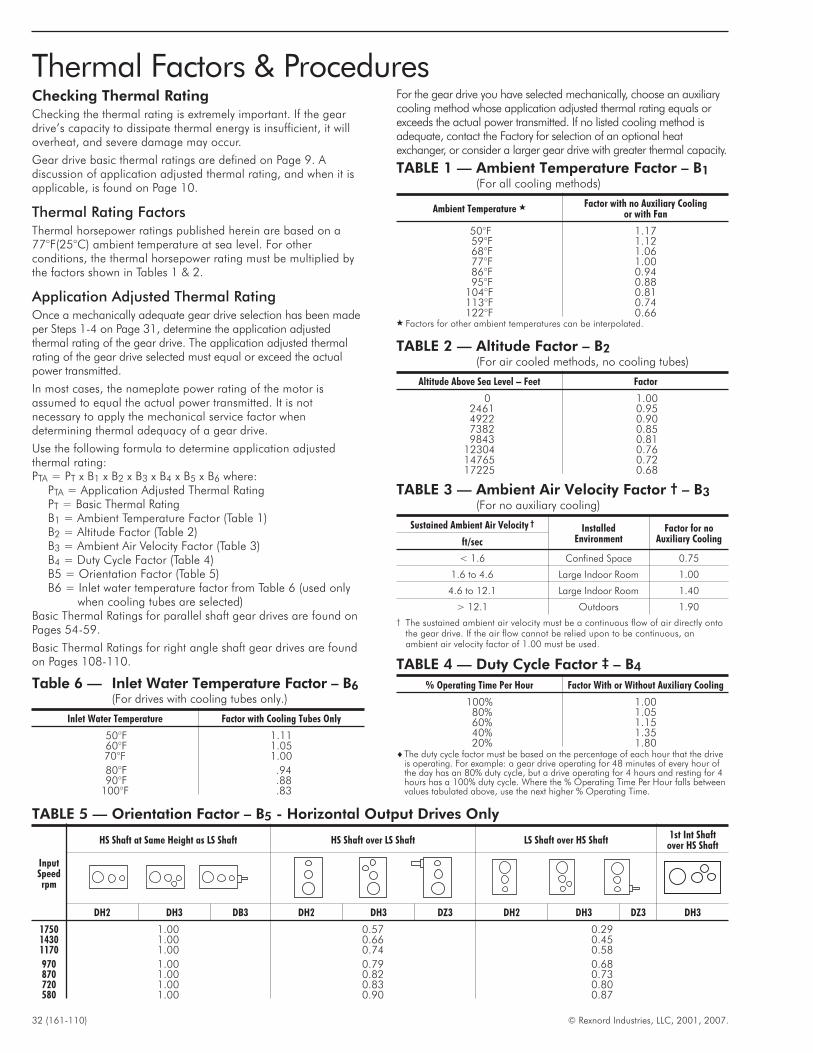
Checking Thermal RatingChecking the thermal rating is extremely important. If the geardrive’s capacity to dissipate thermal energy is insufficient, it willoverheat, and severe damage may occur.
Gear drive basic thermal ratings are defined on Page 9. Adiscussion of application adjusted thermal rating, and when it isapplicable, is found on Page 10.
Thermal Rating FactorsThermal horsepower ratings published herein are based on a77°F(25°C) ambient temperature at sea level. For otherconditions, the thermal horsepower rating must be multiplied bythe factors shown in Tables 1 & 2.
Application Adjusted Thermal RatingOnce a mechanically adequate gear drive selection has been madeper Steps 1-4 on Page 31, determine the application adjustedthermal rating of the gear drive. The application adjusted thermalrating of the gear drive selected must equal or exceed the actualpower transmitted.
In most cases, the nameplate power rating of the motor isassumed to equal the actual power transmitted. It is notnecessary to apply the mechanical service factor whendetermining thermal adequacy of a gear drive.
Use the following formula to determine application adjustedthermal rating:PTA = PT x B1 x B2 x B3 x B4 x B5 x B6 where:
PTA = Application Adjusted Thermal RatingPT = Basic Thermal RatingB1 = Ambient Temperature Factor (Table 1)B2 = Altitude Factor (Table 2)B3 = Ambient Air Velocity Factor (Table 3)B4 = Duty Cycle Factor (Table 4)B5 = Orientation Factor (Table 5)B6 = Inlet water temperature factor from Table 6 (used only
when cooling tubes are selected)Basic Thermal Ratings for parallel shaft gear drives are found onPages 54-59.
Basic Thermal Ratings for right angle shaft gear drives are foundon Pages 108-110.
For the gear drive you have selected mechanically, choose an auxiliarycooling method whose application adjusted thermal rating equals orexceeds the actual power transmitted. If no listed cooling method isadequate, contact the Factory for selection of an optional heatexchanger, or consider a larger gear drive with greater thermal capacity.
32 (161-110) © Rexnord Industries, LLC, 2001, 2007.
TABLE 1 — Ambient Temperature Factor – B1(For all cooling methods)
Ambient Temperature � Factor with no Auxiliary Coolingor with Fan
50°F 1.1759°F 1.1268°F 1.0677°F 1.0086°F 0.9495°F 0.88
104°F 0.81113°F 0.74122°F 0.66
� Factors for other ambient temperatures can be interpolated.
TABLE 2 — Altitude Factor – B2(For air cooled methods, no cooling tubes)
Altitude Above Sea Level – Feet Factor
0 1.002461 0.954922 0.907382 0.859843 0.81
12304 0.7614765 0.7217225 0.68
TABLE 3 — Ambient Air Velocity Factor † – B3(For no auxiliary cooling)
Sustained Ambient Air Velocity †Installed
EnvironmentFactor for no
Auxiliary Coolingft/sec
< 1.6 Confined Space 0.75
1.6 to 4.6 Large Indoor Room 1.00
4.6 to 12.1 Large Indoor Room 1.40
> 12.1 Outdoors 1.90
† The sustained ambient air velocity must be a continuous flow of air directly ontothe gear drive. If the air flow cannot be relied upon to be continuous, anambient air velocity factor of 1.00 must be used.
TABLE 4 — Duty Cycle Factor ‡ – B4
% Operating Time Per Hour Factor With or Without Auxiliary Cooling
100% 1.0080% 1.0560% 1.1540% 1.3520% 1.80
�The duty cycle factor must be based on the percentage of each hour that the driveis operating. For example: a gear drive operating for 48 minutes of every hour ofthe day has an 80% duty cycle, but a drive operating for 4 hours and resting for 4hours has a 100% duty cycle. Where the % Operating Time Per Hour falls betweenvalues tabulated above, use the next higher % Operating Time.
Thermal Factors & Procedures
TABLE 5 — Orientation Factor – B5 - Horizontal Output Drives Only
InputSpeedrpm
HS Shaft at Same Height as LS Shaft HS Shaft over LS Shaft LS Shaft over HS Shaft1st Int Shaft
over HS Shaft
DH2 DH3 DB3 DH2 DH3 DZ3 DH2 DH3 DZ3 DH3
1750 1.00 0.57 0.291430 1.00 0.66 0.451170 1.00 0.74 0.58
970 1.00 0.79 0.68870 1.00 0.82 0.73720 1.00 0.83 0.80580 1.00 0.90 0.87
Table 6 — Inlet Water Temperature Factor – B6(For drives with cooling tubes only.)
Inlet Water Temperature Factor with Cooling Tubes Only
50°F 1.1160°F 1.0570°F 1.00
80°F .9490°F .88
100°F .83
Power Selection ExampleA draw bench operates 10 hours per day. The gear driverequired for the application is driven at the high speed shaft by a100 HP electric motor at 1170 RPM. A low speed shaft speed of42 RPM at the gear drive has been requested.
Ambient temperature at the draw bench never exceeds 80º F. Thedraw bench is located in a small indoor room, with air flow lessthan 1.6 feet per second. Altitude above sea level is 1000 feet.The high speed and low speed shafts of the selected gear drivewill be connected to the driving and driven equipment by flexiblecouplings. Select a base-mounted parallel shaft gear drive forthis application as follows:
1. The mechanical service factor is 1.25 for a draw bench driveoperating 10 hours per day, from Page 12, Table 3 (MetalMills).
2. The equivalent power in HP = 1.25 x 100 = 125 HP.
3. The ideal ratio is 1170 ÷ 42 = 27.86. The closest nominalratio is 28.0:1 from the Double Reduction Power Ratings Tableon Page 46.
4. Using the Double Reduction Power Ratings Table on Page 46,and in the section associated with a nominal ratio of 28.0:1,trace right through the columns to the first power rating thatequals or exceeds the equivalent power of 125 HP calculatedin Step 2. The selection is a size M1160 (shown at the top ofthe column) that has a power rating of 135 HP.Actual mechanical service factor is 135 ÷ 100 = 1.35.Exact ratio is 27.36:1, found on Page 67 (exact ratio table)
5. Check thermal rating. The application adjusted thermal ratingmust equal or exceed the actual power transmitted (100HP).Basic thermal rating for the size M1160DH2, nominal ratio28:1, high speed shaft at 1170 RPM, no auxiliary cooling,equals 201 HP, per Page 56.
Thermal factors from Page 32 for no auxiliary cooling are asfollows:
B1 = Ambient Temperature Factor from Thermal Table 1 =1.00
B2 = Altitude factor from Thermal Table 2 = 1.00
B3 = Ambient Air Velocity Factor from Thermal Table 3 =0.75
B4 = Duty Cycle Factor from Thermal Table 4 = 1.00
B5 = Orientation factor from Thermal Table 5 = 1.00
Application Adjusted Thermal rating with no auxiliarycooling = 201 x 1.00 x 1.00 x 0.75 x 1.00 x 1.00 = 151THP
Application Adjusted Thermal rating does equal or exceed the100 HP transmitted, no auxiliary cooling is required.
6. It is not necessary to check overhung load or thrust capacity ofthe gear drive for this example. Gear drive shaft extensionsare connected by flexible couplings, which do not imposesignificant overhung load. No thrust load is present.
Torque Selection ExampleA dredge utility winch requires 200,000 Lb.-in. of torque at itsoutput shaft, which operates at 16 RPM. The winch is in service 8hours per day and is driven by a coupling-connected 60 HP,1750 RPM electric motor. The ambient temperature neverexceeds 75º F. The approximate air velocity is 10 feet persecond, and the dredge operates in the North Sea (sea level).The winch never operates more than 30 minutes in a given hour.The space available is best suited to a base mounted right anglegear drive. Select a gear drive for this application.
1. The Service Factor is 1.25 for a dredge utility winch operating10 hours per day, from Page 11, Table 2 under Dredges.
2. The equivalent torque is 1.25 x 200,000 = 250,000 Lb.-in.
3. The ideal ratio is 1750 ÷ 16 = 109.4:1. The neareststandard nominal ratio is 112:1 from the Right Angle TripleReduction Table on Page 104.
4. Using the Triple Reduction Table on Page 104, in the 1750RPM high speed shaft section and at the 112:1 ratio and 16RPM, trace right to 286 (x 1000, the first torque exceeding theequivalent torque of 250,000 Lb.-in.) and read the drive sizeM1170 at the top of the column.
5. The basic thermal capacity with no auxiliary cooling for anM1170DB3, 112:1, at 1750 RPM from the table on Page109 is 119 HP. The ambient temperature factor (B1) fromTable 1, Page 32, is 1.00. The altitude factor (B2) from Table2, Page 32 is 1.00. The ambient air velocity factor (B3) is 1.4from Table 3, Page 32. The Duty Cycle is 50% (30 min /hour), so the duty cycle factor (B4) is 1.15 from Table 4, Page32. The Orientation factor (B5) is 1.00, from Table 5, Page32.
6. The application adjusted thermal capacity is 119 x 1.00 x1.00 x 1.40 x 1.15 x 1.00 = 191.6 HP, which exceeds thepower rating of the motor (60 HP). Therefore, no additionalcooling is required.
7. It is not necessary to check overhung load or thrust capacity ofthe gear drive for this example. Gear drive shaft extensionsare connected by flexible couplings, which do not imposesignificant overhung load. No thrust load is present.
© Rexnord Industries, LLC, 2001, 2007. (161-110) 33
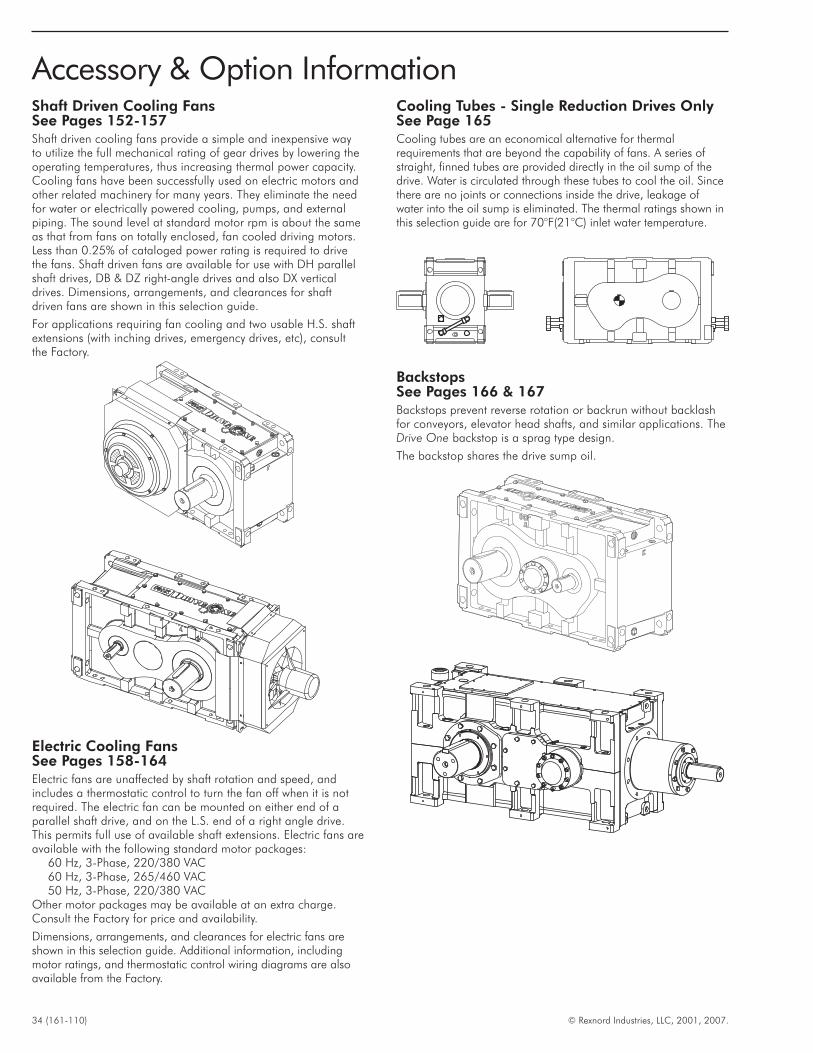
Shaft Driven Cooling FansSee Pages 152-157Shaft driven cooling fans provide a simple and inexpensive wayto utilize the full mechanical rating of gear drives by lowering theoperating temperatures, thus increasing thermal power capacity.Cooling fans have been successfully used on electric motors andother related machinery for many years. They eliminate the needfor water or electrically powered cooling, pumps, and externalpiping. The sound level at standard motor rpm is about the sameas that from fans on totally enclosed, fan cooled driving motors.Less than 0.25% of cataloged power rating is required to drivethe fans. Shaft driven fans are available for use with DH parallelshaft drives, DB & DZ right-angle drives and also DX verticaldrives. Dimensions, arrangements, and clearances for shaftdriven fans are shown in this selection guide.
For applications requiring fan cooling and two usable H.S. shaftextensions (with inching drives, emergency drives, etc), consultthe Factory.
Electric Cooling FansSee Pages 158-164Electric fans are unaffected by shaft rotation and speed, andincludes a thermostatic control to turn the fan off when it is notrequired. The electric fan can be mounted on either end of aparallel shaft drive, and on the L.S. end of a right angle drive.This permits full use of available shaft extensions. Electric fans areavailable with the following standard motor packages:
60 Hz, 3-Phase, 220/380 VAC60 Hz, 3-Phase, 265/460 VAC50 Hz, 3-Phase, 220/380 VAC
Other motor packages may be available at an extra charge.Consult the Factory for price and availability.
Dimensions, arrangements, and clearances for electric fans areshown in this selection guide. Additional information, includingmotor ratings, and thermostatic control wiring diagrams are alsoavailable from the Factory.
Cooling Tubes - Single Reduction Drives OnlySee Page 165Cooling tubes are an economical alternative for thermalrequirements that are beyond the capability of fans. A series ofstraight, finned tubes are provided directly in the oil sump of thedrive. Water is circulated through these tubes to cool the oil. Sincethere are no joints or connections inside the drive, leakage ofwater into the oil sump is eliminated. The thermal ratings shown inthis selection guide are for 70°F(21°C) inlet water temperature.
BackstopsSee Pages 166 & 167Backstops prevent reverse rotation or backrun without backlashfor conveyors, elevator head shafts, and similar applications. TheDrive One backstop is a sprag type design.
The backstop shares the drive sump oil.
34 (161-110) © Rexnord Industries, LLC, 2001, 2007.
Accessory & Option Information
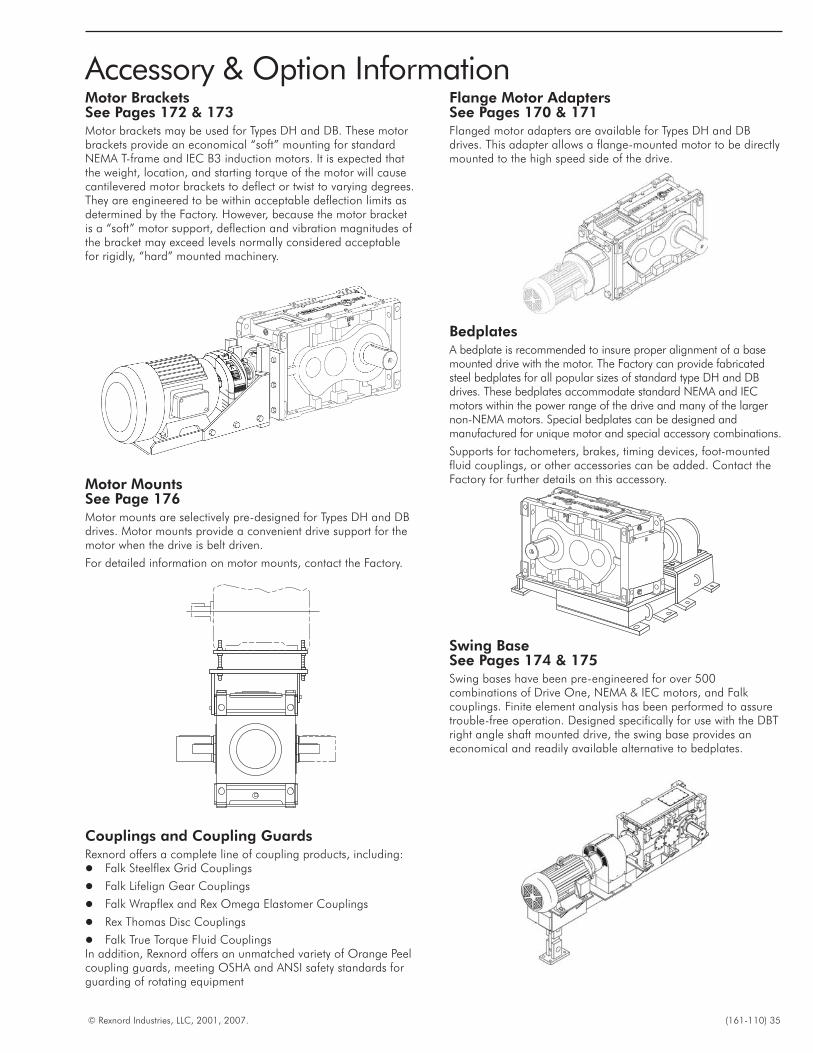
Motor BracketsSee Pages 172 & 173Motor brackets may be used for Types DH and DB. These motorbrackets provide an economical “soft” mounting for standardNEMA T-frame and IEC B3 induction motors. It is expected thatthe weight, location, and starting torque of the motor will causecantilevered motor brackets to deflect or twist to varying degrees.They are engineered to be within acceptable deflection limits asdetermined by the Factory. However, because the motor bracketis a “soft” motor support, deflection and vibration magnitudes ofthe bracket may exceed levels normally considered acceptablefor rigidly, “hard” mounted machinery.
Motor MountsSee Page 176Motor mounts are selectively pre-designed for Types DH and DBdrives. Motor mounts provide a convenient drive support for themotor when the drive is belt driven.
For detailed information on motor mounts, contact the Factory.
Couplings and Coupling GuardsRexnord offers a complete line of coupling products, including:� Falk Steelflex Grid Couplings
� Falk Lifelign Gear Couplings
� Falk Wrapflex and Rex Omega Elastomer Couplings
� Rex Thomas Disc Couplings
� Falk True Torque Fluid CouplingsIn addition, Rexnord offers an unmatched variety of Orange Peelcoupling guards, meeting OSHA and ANSI safety standards forguarding of rotating equipment
Flange Motor AdaptersSee Pages 170 & 171Flanged motor adapters are available for Types DH and DBdrives. This adapter allows a flange-mounted motor to be directlymounted to the high speed side of the drive.
BedplatesA bedplate is recommended to insure proper alignment of a basemounted drive with the motor. The Factory can provide fabricatedsteel bedplates for all popular sizes of standard type DH and DBdrives. These bedplates accommodate standard NEMA and IECmotors within the power range of the drive and many of the largernon-NEMA motors. Special bedplates can be designed andmanufactured for unique motor and special accessory combinations.
Supports for tachometers, brakes, timing devices, foot-mountedfluid couplings, or other accessories can be added. Contact theFactory for further details on this accessory.
Swing BaseSee Pages 174 & 175Swing bases have been pre-engineered for over 500combinations of Drive One, NEMA & IEC motors, and Falkcouplings. Finite element analysis has been performed to assuretrouble-free operation. Designed specifically for use with the DBTright angle shaft mounted drive, the swing base provides aneconomical and readily available alternative to bedplates.
© Rexnord Industries, LLC, 2001, 2007. (161-110) 35
Accessory & Option Information
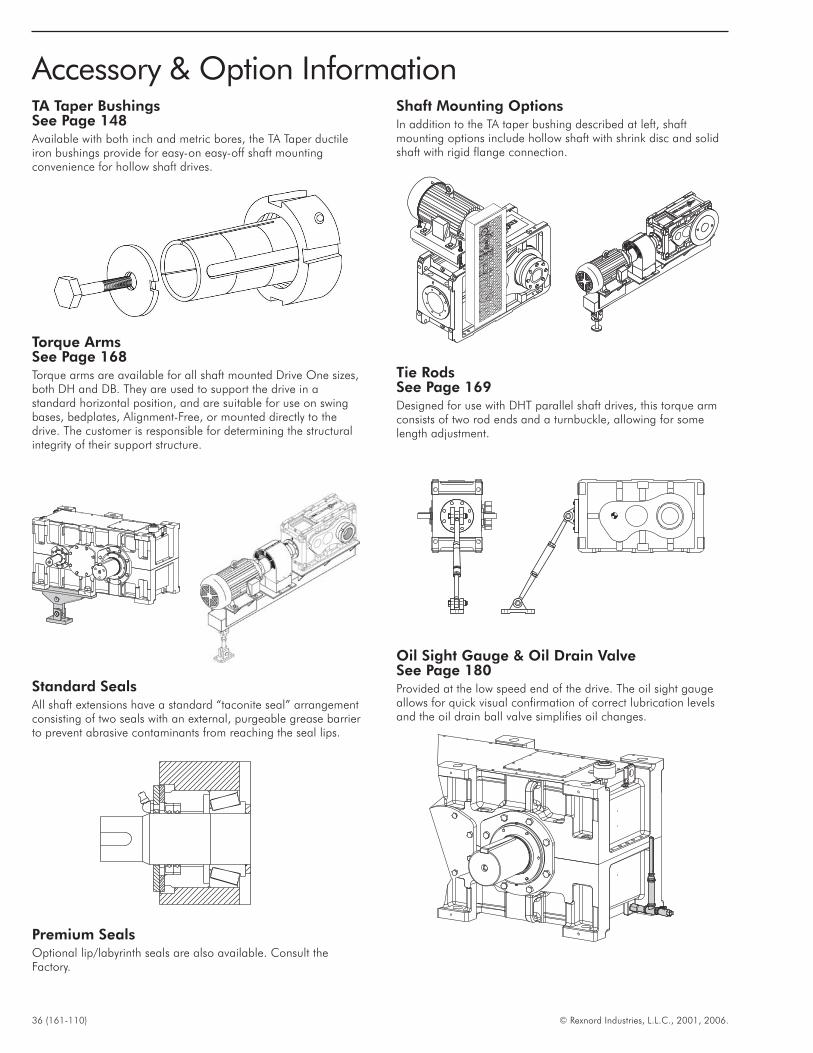
TA Taper BushingsSee Page 148Available with both inch and metric bores, the TA Taper ductileiron bushings provide for easy-on easy-off shaft mountingconvenience for hollow shaft drives.
Torque ArmsSee Page 168Torque arms are available for all shaft mounted Drive One sizes,both DH and DB. They are used to support the drive in astandard horizontal position, and are suitable for use on swingbases, bedplates, Alignment-Free, or mounted directly to thedrive. The customer is responsible for determining the structuralintegrity of their support structure.
Standard SealsAll shaft extensions have a standard “taconite seal” arrangementconsisting of two seals with an external, purgeable grease barrierto prevent abrasive contaminants from reaching the seal lips.
Premium SealsOptional lip/labyrinth seals are also available. Consult theFactory.
Shaft Mounting OptionsIn addition to the TA taper bushing described at left, shaftmounting options include hollow shaft with shrink disc and solidshaft with rigid flange connection.
Tie RodsSee Page 169Designed for use with DHT parallel shaft drives, this torque armconsists of two rod ends and a turnbuckle, allowing for somelength adjustment.
Oil Sight Gauge & Oil Drain ValveSee Page 180Provided at the low speed end of the drive. The oil sight gaugeallows for quick visual confirmation of correct lubrication levelsand the oil drain ball valve simplifies oil changes.
36 (161-110) © Rexnord Industries, L.L.C., 2001, 2006.
Accessory & Option Information
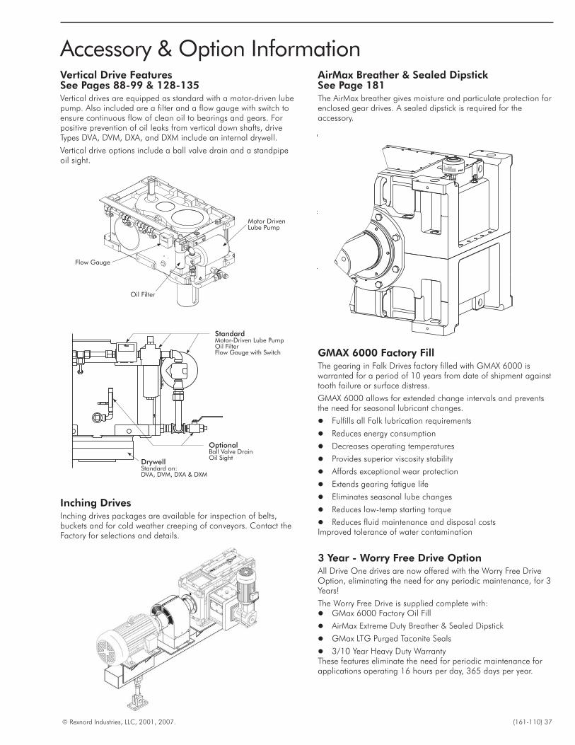
Vertical Drive FeaturesSee Pages 88-99 & 128-135Vertical drives are equipped as standard with a motor-driven lubepump. Also included are a filter and a flow gauge with switch toensure continuous flow of clean oil to bearings and gears. Forpositive prevention of oil leaks from vertical down shafts, driveTypes DVA, DVM, DXA, and DXM include an internal drywell.
Vertical drive options include a ball valve drain and a standpipeoil sight.
Inching DrivesInching drives packages are available for inspection of belts,buckets and for cold weather creeping of conveyors. Contact theFactory for selections and details.
AirMax Breather & Sealed DipstickSee Page 181The AirMax breather gives moisture and particulate protection forenclosed gear drives. A sealed dipstick is required for theaccessory.
GMAX 6000 Factory FillThe gearing in Falk Drives factory filled with GMAX 6000 iswarranted for a period of 10 years from date of shipment againsttooth failure or surface distress.
GMAX 6000 allows for extended change intervals and preventsthe need for seasonal lubricant changes.
� Fulfills all Falk lubrication requirements
� Reduces energy consumption
� Decreases operating temperatures
� Provides superior viscosity stability
� Affords exceptional wear protection
� Extends gearing fatigue life
� Eliminates seasonal lube changes
� Reduces low-temp starting torque
� Reduces fluid maintenance and disposal costsImproved tolerance of water contamination
3 Year - Worry Free Drive OptionAll Drive One drives are now offered with the Worry Free DriveOption, eliminating the need for any periodic maintenance, for 3Years!
The Worry Free Drive is supplied complete with:� GMax 6000 Factory Oil Fill
� AirMax Extreme Duty Breather & Sealed Dipstick
� GMax LTG Purged Taconite Seals
� 3/10 Year Heavy Duty WarrantyThese features eliminate the need for periodic maintenance forapplications operating 16 hours per day, 365 days per year.
© Rexnord Industries, LLC, 2001, 2007. (161-110) 37
Accessory & Option Information
StandardMotor-Driven Lube PumpOil FilterFlow Gauge with Switch
OptionalBall Valve DrainOil Sight
DrywellStandard on:DVA, DVM, DXA & DXM
Motor DrivenLube Pump
Oil Filter
Flow Gauge
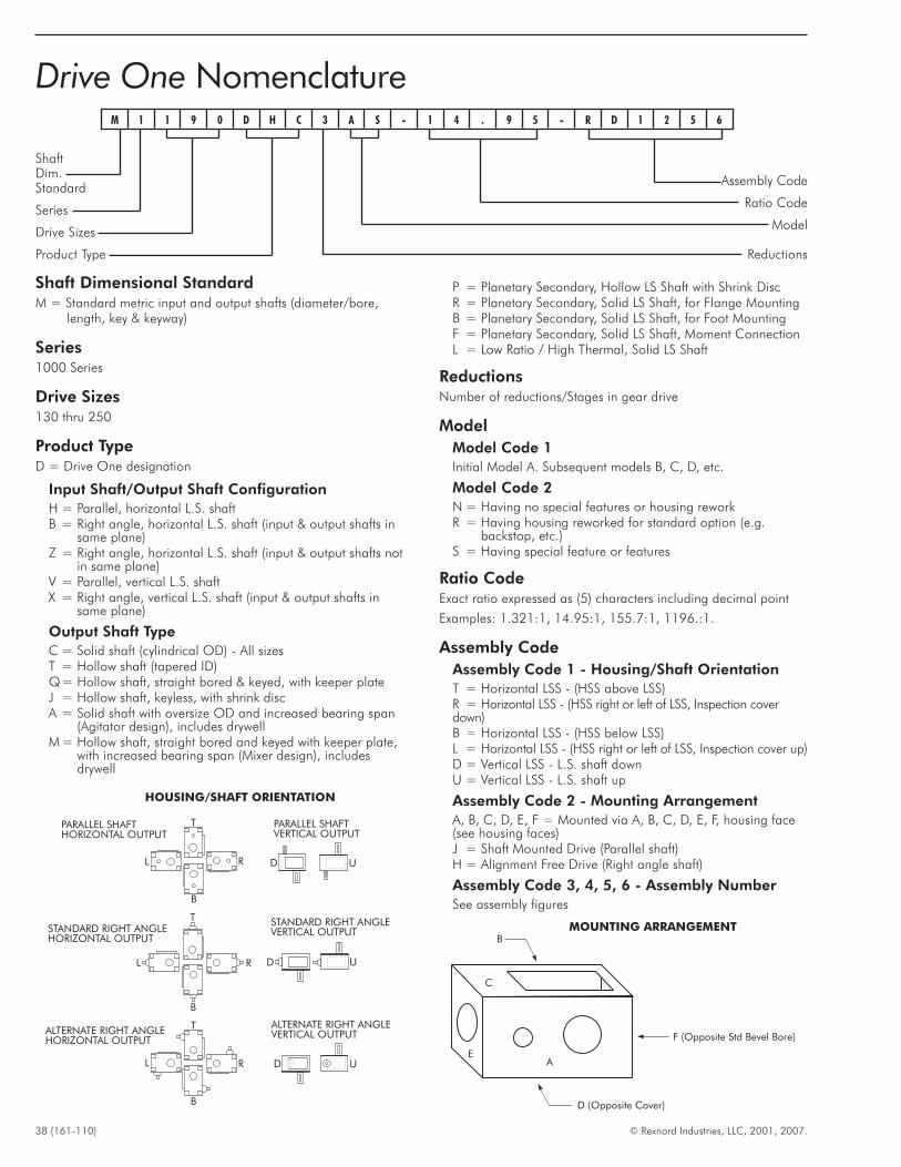
ShaftDim.Standard
Series
Drive Sizes
Product Type
Shaft Dimensional StandardM = Standard metric input and output shafts (diameter/bore,
length, key & keyway)
Series1000 Series
Drive Sizes130 thru 250
Product TypeD = Drive One designation
Input Shaft/Output Shaft Configuration
H = Parallel, horizontal L.S. shaftB = Right angle, horizontal L.S. shaft (input & output shafts in
same plane)Z = Right angle, horizontal L.S. shaft (input & output shafts not
in same plane)V = Parallel, vertical L.S. shaftX = Right angle, vertical L.S. shaft (input & output shafts in
same plane)
Output Shaft Type
C = Solid shaft (cylindrical OD) - All sizesT = Hollow shaft (tapered ID)Q= Hollow shaft, straight bored & keyed, with keeper plateJ = Hollow shaft, keyless, with shrink discA = Solid shaft with oversize OD and increased bearing span
(Agitator design), includes drywellM = Hollow shaft, straight bored and keyed with keeper plate,
with increased bearing span (Mixer design), includesdrywell
Assembly Code
Ratio Code
Model
Reductions
P = Planetary Secondary, Hollow LS Shaft with Shrink DiscR = Planetary Secondary, Solid LS Shaft, for Flange MountingB = Planetary Secondary, Solid LS Shaft, for Foot MountingF = Planetary Secondary, Solid LS Shaft, Moment ConnectionL = Low Ratio / High Thermal, Solid LS Shaft
ReductionsNumber of reductions/Stages in gear drive
Model
Model Code 1
Initial Model A. Subsequent models B, C, D, etc.
Model Code 2
N = Having no special features or housing reworkR = Having housing reworked for standard option (e.g.
backstop, etc.)S = Having special feature or features
Ratio CodeExact ratio expressed as (5) characters including decimal point
Examples: 1.321:1, 14.95:1, 155.7:1, 1196.:1.
Assembly Code
Assembly Code 1 - Housing/Shaft Orientation
T = Horizontal LSS - (HSS above LSS)R = Horizontal LSS - (HSS right or left of LSS, Inspection coverdown)B = Horizontal LSS - (HSS below LSS)L = Horizontal LSS - (HSS right or left of LSS, Inspection cover up)D = Vertical LSS - L.S. shaft downU = Vertical LSS - L.S. shaft up
Assembly Code 2 - Mounting Arrangement
A, B, C, D, E, F = Mounted via A, B, C, D, E, F, housing face(see housing faces)J = Shaft Mounted Drive (Parallel shaft)H = Alignment Free Drive (Right angle shaft)
Assembly Code 3, 4, 5, 6 - Assembly Number
See assembly figures
38 (161-110) © Rexnord Industries, LLC, 2001, 2007.
Drive One NomenclatureM 1 1 9 0 D H C 3 A S - 1 4 . 9 5 - R D 1 2 5 6
T
R
B
L
T
R
B
L
T
R
B
L
D U
D U
D U
HOUSING/SHAFT ORIENTATION
PARALLEL SHAFTHORIZONTAL OUTPUT
STANDARD RIGHT ANGLEHORIZONTAL OUTPUT
ALTERNATE RIGHT ANGLEHORIZONTAL OUTPUT
PARALLEL SHAFTVERTICAL OUTPUT
STANDARD RIGHT ANGLEVERTICAL OUTPUT
ALTERNATE RIGHT ANGLEVERTICAL OUTPUT
B
F (Opposite Std Bevel Bore)
A
C
E
D (Opposite Cover)
MOUNTING ARRANGEMENT
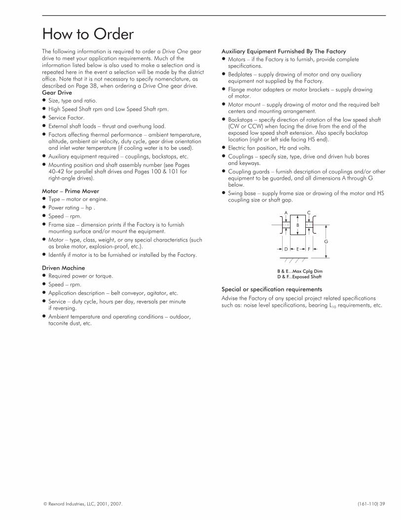
The following information is required to order a Drive One geardrive to meet your application requirements. Much of theinformation listed below is also used to make a selection and isrepeated here in the event a selection will be made by the districtoffice. Note that it is not necessary to specify nomenclature, asdescribed on Page 38, when ordering a Drive One gear drive.Gear Drive� Size, type and ratio.
� High Speed Shaft rpm and Low Speed Shaft rpm.
� Service Factor.
� External shaft loads – thrust and overhung load.
� Factors affecting thermal performance – ambient temperature,altitude, ambient air velocity, duty cycle, gear drive orientationand inlet water temperature (if cooling water is to be used).
� Auxiliary equipment required – couplings, backstops, etc.
� Mounting position and shaft assembly number (see Pages40-42 for parallel shaft drives and Pages 100 & 101 forright-angle drives).
Motor – Prime Mover� Type – motor or engine.
� Power rating – hp .
� Speed – rpm.
� Frame size – dimension prints if the Factory is to furnishmounting surface and/or mount the equipment.
� Motor – type, class, weight, or any special characteristics (suchas brake motor, explosion-proof, etc.).
� Identify if motor is to be furnished or installed by the Factory.
Driven Machine� Required power or torque.
� Speed – rpm.
� Application description – belt conveyor, agitator, etc.
� Service – duty cycle, hours per day, reversals per minuteif reversing.
� Ambient temperature and operating conditions – outdoor,taconite dust, etc.
Auxiliary Equipment Furnished By The Factory� Motors – if the Factory is to furnish, provide complete
specifications.
� Bedplates – supply drawing of motor and any auxiliaryequipment not supplied by the Factory.
� Flange motor adapters or motor brackets – supply drawingof motor.
� Motor mount – supply drawing of motor and the required beltcenters and mounting arrangement.
� Backstops – specify direction of rotation of the low speed shaft(CW or CCW) when facing the drive from the end of theexposed low speed shaft extension. Also specify backstoplocation (right or left side facing HS end).
� Electric fan position, Hz and volts.
� Couplings – specify size, type, drive and driven hub boresand keyways.
� Coupling guards – furnish description of couplings and/or otherequipment to be guarded, and all dimensions A through Gbelow.
� Swing base – supply frame size or drawing of the motor and HScoupling size or shaft gap.
Special or specification requirements
Advise the Factory of any special project related specificationssuch as: noise level specifications, bearing L10 requirements, etc.
© Rexnord Industries, LLC, 2001, 2007. (161-110) 39
How to Order
A C
B
D E F
G
B & E...Max Cplg DimD & F...Exposed Shaft
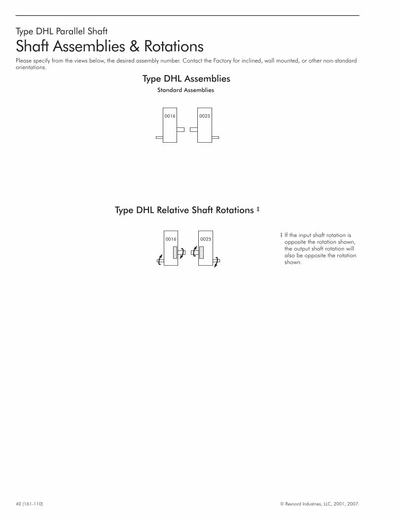
40 (161-110) © Rexnord Industries, LLC, 2001, 2007.
Type DHL Parallel Shaft
Shaft Assemblies & RotationsPlease specify from the views below, the desired assembly number. Contact the Factory for inclined, wall mounted, or other non-standardorientations.
Standard Assemblies
Type DHL Relative Shaft Rotations ‡
‡ If the input shaft rotation isopposite the rotation shown,the output shaft rotation willalso be opposite the rotationshown.
Type DHL Assemblies
0016 0025
0016 0025
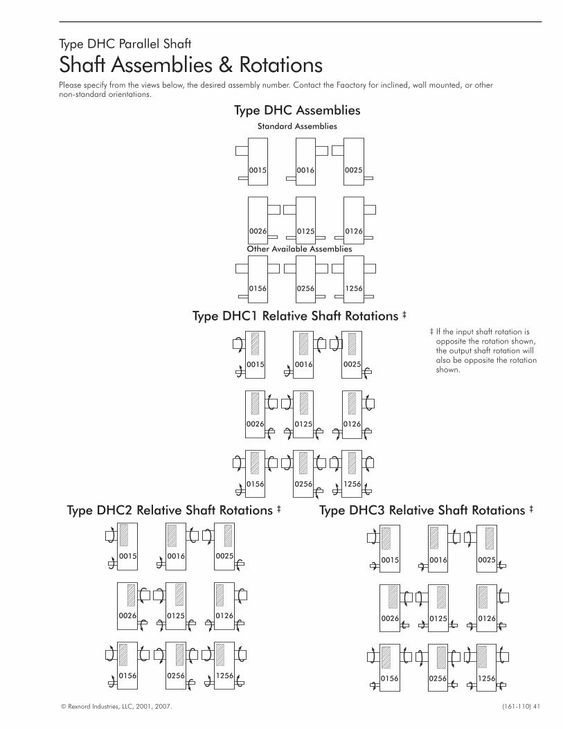
© Rexnord Industries, LLC, 2001, 2007. (161-110) 41
Type DHC Parallel Shaft
Shaft Assemblies & RotationsPlease specify from the views below, the desired assembly number. Contact the Faactory for inclined, wall mounted, or othernon-standard orientations.
Type DHC AssembliesStandard Assemblies
002500160015
0026 0125 0126
125602560156
Type DHC2 Relative Shaft Rotations ‡
002500160015
0026 0125 0126
125602560156
Type DHC3 Relative Shaft Rotations ‡
002500160015
0026 0125 0126
125602560156
Other Available Assemblies
Type DHC1 Relative Shaft Rotations ‡
002500160015
0026 0125 0126
125602560156
‡ If the input shaft rotation isopposite the rotation shown,the output shaft rotation willalso be opposite the rotationshown.
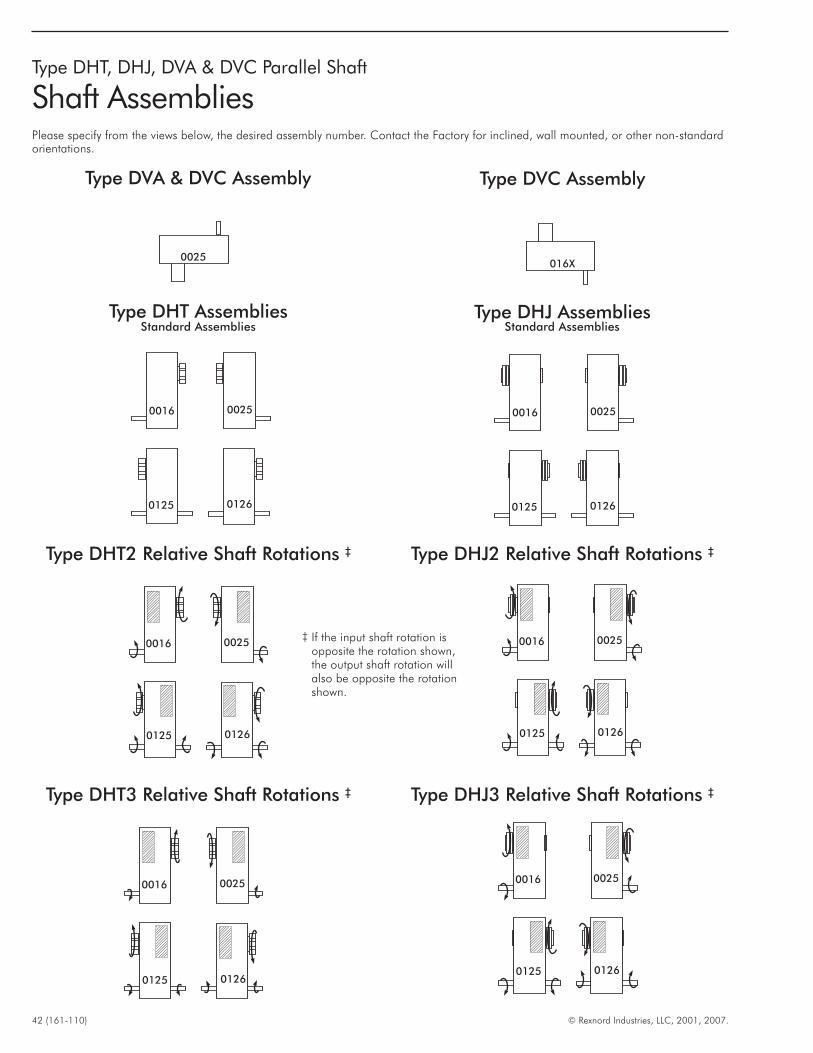
42 (161-110) © Rexnord Industries, LLC, 2001, 2007.
Type DHT, DHJ, DVA & DVC Parallel Shaft
Shaft AssembliesPlease specify from the views below, the desired assembly number. Contact the Factory for inclined, wall mounted, or other non-standardorientations.
0125 0126
00250016
Type DHT AssembliesStandard Assemblies
Type DHT2 Relative Shaft Rotations ‡
0125 0126
00250016
Type DHT3 Relative Shaft Rotations ‡
0125 0126
00250016
‡ If the input shaft rotation isopposite the rotation shown,the output shaft rotation willalso be opposite the rotationshown.
Type DHJ AssembliesStandard Assemblies
0125 0126
00250016
Type DHJ2 Relative Shaft Rotations ‡
0125 0126
00250016
Type DHJ3 Relative Shaft Rotations ‡
0125 0126
00250016
Type DVA & DVC Assembly Type DVC Assembly
0025016X

© Rexnord Industries, LLC, 2001, 2007. (161-110) 43
THIS PAGE INTENTIONALLY LEFT BLANK
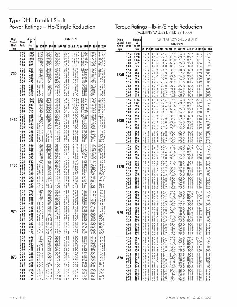
44 (161-110) © Rexnord Industries, LLC, 2001, 2007.
Type DHL Parallel ShaftPower Ratings – Hp/Single Reduction Torque Ratings – lb-in/Single Reduction
(MULTIPLY VALUES LISTED BY 1000)
HighSpeedShaftrpm
NomRatio
ApproxLS
Shaftrpm
(LB-IN AT LOW SPEED SHAFT)
DRIVE SIZE
M1130 M1140 M1150 M1160 M1170 M1180 M1190 M1200
1750
1.25 1400 12.4 15.3 26.4 37.2 56.8 77.6 89.9 1401.40 1250 12.9 16.6 29.7 41.9 63.9 85.6 96.6 1541.60 1094 12.9 17.5 34.4 45.0 71.9 89.5 101 1741.80 972 12.8 18.6 34.5 46.4 75.8 95.1 106 1752.00 875 12.8 19.3 34.0 48.7 76.7 100 114 179
2.24 781 12.9 20.2 34.7 50.7 78.0 103 119 2092.50 700 12.9 21.9 33.3 50.1 77.7 87.5 123 2022.80 625 12.8 23.0 33.2 49.0 76.3 98.6 128 2133.15 556 12.9 22.1 32.9 48.6 76.9 112 132 1853.55 493 12.6 19.6 25.5 40.2 71.5 88.9 139 183
4.00 438 12.3 19.7 28.8 39.4 65.0 100 147 1914.50 389 12.2 19.3 29.2 43.9 66.3 106 144 2005.00 350 12.2 20.5 28.5 43.8 74.2 107 161 2085.60 313 12.0 20.6 31.7 45.8 68.9 103 140 200
1430
1.25 1144 12.4 15.3 26.4 37.2 56.8 77.6 94.7 1401.40 1021 12.9 16.6 29.7 41.9 63.9 85.6 102 1541.60 894 12.9 17.5 34.4 45.0 71.9 89.5 106 1771.80 794 12.9 18.6 34.5 46.4 75.8 95.1 112 1862.00 715 12.9 19.3 34.1 48.7 76.7 100 120 191
2.24 638 12.9 20.2 35.1 50.7 78.0 103 126 2152.50 572 12.9 22.7 33.9 50.4 77.7 87.5 130 2142.80 511 12.9 23.3 33.8 49.6 76.3 98.6 134 2263.15 454 12.9 22.5 33.5 49.6 77.5 112 139 1853.55 403 12.8 19.6 25.5 42.7 74.9 88.9 139 183
4.00 358 12.4 21.0 28.8 39.4 65.0 100 155 2034.50 318 12.3 19.3 31.0 44.3 70.4 112 152 2125.00 286 12.3 21.3 28.5 46.5 75.3 112 163 2215.60 255 12.1 21.9 31.7 46.4 73.2 110 147 212
1170
1.25 936 12.7 15.3 26.4 37.2 56.8 77.6 94.7 1401.40 836 12.9 16.6 29.7 41.9 63.9 85.6 106 1541.60 731 12.9 17.5 34.4 45.0 71.9 89.5 114 1771.80 650 12.9 18.6 35.0 46.4 75.8 95.1 120 1952.00 585 12.9 19.3 34.8 48.7 76.7 100 128 200
2.24 522 12.9 20.2 35.7 51.0 78.3 103 134 2152.50 468 12.9 23.0 34.5 51.3 78.6 87.5 139 2262.80 418 12.9 23.6 34.3 50.5 77.8 98.6 144 2403.15 371 12.9 22.7 33.9 50.4 78.9 114 149 1853.55 330 12.9 19.6 25.5 45.0 75.8 88.9 139 183
4.00 293 12.5 22.3 28.8 39.4 65.0 100 163 2154.50 260 12.4 19.3 32.9 44.3 73.6 113 163 2255.00 234 12.4 21.3 28.5 48.1 76.2 114 163 2345.60 209 12.2 22.2 31.7 46.9 75.3 114 158 225
970
1.25 776 12.9 15.3 26.4 37.2 56.8 77.6 94.7 1401.40 693 12.9 16.6 29.7 41.9 63.9 85.6 106 1541.60 606 12.9 17.5 34.4 45.0 71.9 89.5 116 1771.80 539 12.9 18.6 35.6 46.4 76.4 95.1 121 1952.00 485 12.9 19.3 35.3 48.7 77.7 100 128 200
2.24 433 12.9 20.2 36.2 51.0 79.8 103 134 2152.50 388 12.9 23.2 34.9 52.1 79.9 87.5 139 2262.80 346 12.9 23.9 34.7 51.1 79.0 98.6 145 2493.15 308 12.9 23.0 34.3 51.0 80.0 116 158 1853.55 273 12.9 19.6 25.5 45.0 75.8 88.9 139 183
4.00 243 12.6 22.5 28.8 39.4 65.0 100 163 2174.50 216 12.5 19.3 33.0 44.3 73.6 115 163 2385.00 194 12.5 21.3 28.5 48.1 76.9 115 163 2465.60 173 12.3 22.3 31.7 47.2 75.9 115 163 238
870
1.25 696 12.9 15.3 26.4 37.2 56.8 77.6 94.7 1401.40 621 12.9 16.6 29.7 41.9 63.9 85.6 106 1541.60 544 12.9 17.5 34.4 45.0 71.9 89.5 116 1771.80 483 12.9 18.6 35.9 46.4 77.2 95.1 121 1952.00 435 12.9 19.3 35.6 48.7 78.5 100 128 200
2.24 388 12.9 20.2 36.4 51.0 80.5 103 134 2152.50 348 12.9 23.4 35.1 52.4 80.6 87.5 139 2262.80 311 12.9 24.0 34.9 51.5 79.6 98.6 145 2523.15 276 12.9 23.1 34.5 51.3 80.6 117 163 1853.55 245 12.9 19.6 25.5 45.0 75.8 88.9 139 183
4.00 218 12.6 22.5 28.8 39.4 65.0 100 163 2174.50 193 12.5 19.3 33.0 44.3 73.6 115 163 2465.00 174 12.5 21.3 28.5 48.1 77.3 116 163 2485.60 155 12.3 22.4 31.7 47.4 76.2 115 163 246
HighSpeedShaftrpm
NomRatio
ApproxLS
Shaftrpm
DRIVE SIZE
M1130 M1140 M1150 M1160 M1170 M1180 M1190 M1200
750
1.25 1400 272 342 589 827 1267 1706 1998 31001.40 1250 254 328 589 823 1267 1677 1924 31001.60 1094 225 303 589 785 1267 1558 1749 30551.80 972 198 288 525 709 1173 1490 1658 26752.00 875 175 272 465 667 1081 1371 1604 2527
2.24 781 160 249 432 627 967 1260 1467 26162.50 700 144 243 365 553 856 966 1366 22232.80 625 126 229 327 487 751 993 1281 21023.15 556 114 195 287 430 685 979 1154 16303.55 493 98.5 154 202 311 561 689 1098 1441
4.00 438 86.1 136 202 270 456 704 1010 13384.50 389 75.5 120 179 268 411 655 902 12505.00 350 68.4 115 156 246 407 589 905 11655.60 313 60.8 101 156 230 340 520 694 1003
1430
1.25 1144 223 279 481 676 1036 1394 1767 25331.40 1021 208 268 481 673 1036 1371 1703 25331.60 894 184 248 481 641 1036 1273 1548 25331.80 794 164 235 429 579 958 1218 1468 23232.00 715 145 222 381 545 883 1120 1420 2194
2.24 638 131 203 356 513 790 1030 1299 22042.50 572 118 206 304 454 700 789 1209 19302.80 511 104 191 272 403 613 811 1134 18253.15 454 93.0 162 239 358 564 800 1021 13323.55 403 81.4 126 165 270 480 563 922 1177
4.00 358 71.0 118 165 221 373 575 894 11624.50 318 62.2 97.7 155 221 357 562 799 10855.00 286 56.3 97.7 128 214 338 505 767 10115.60 255 50.1 88.1 128 191 295 451 614 870
1170
1.25 936 186 229 394 553 847 1141 1406 20731.40 836 170 220 394 551 847 1121 1406 20731.60 731 150 203 394 525 847 1042 1320 20731.80 650 134 193 357 474 784 996 1251 19912.00 585 118 182 318 446 723 917 1205 1887
2.24 522 107 166 297 422 649 843 1104 18032.50 468 96.5 171 252 379 579 646 1030 16642.80 418 85.3 158 226 335 512 664 966 15863.15 371 76.1 134 198 298 470 664 870 10903.55 330 67.2 103 135 233 397 461 734 963
4.00 293 58.6 102 135 181 305 471 748 10104.50 260 51.3 79.9 135 181 305 467 681 9435.00 234 46.4 79.9 105 181 280 419 611 8795.60 209 41.2 73.3 105 157 248 381 523 756
970
1.25 776 157 190 326 458 703 946 1166 17181.40 693 141 182 326 456 703 930 1166 17181.60 606 125 168 326 435 703 863 1114 17181.80 539 111 160 300 393 655 826 1048 16512.00 485 98.2 151 268 370 608 760 999 1564
2.24 433 88.7 138 249 350 548 699 916 14952.50 388 80.0 143 212 319 488 535 854 13802.80 346 70.7 132 189 282 431 550 806 13633.15 308 63.1 112 166 250 395 560 763 9043.55 273 55.9 85.5 112 193 329 382 609 798
4.00 243 48.9 85.5 112 150 253 390 620 8424.50 216 42.8 66.3 112 150 253 392 565 8275.00 194 38.7 66.3 86.7 150 234 351 506 7655.60 173 34.3 61.1 86.7 131 207 319 448 663
870
1.25 696 141 170 293 411 630 848 1046 15411.40 621 127 163 293 409 630 834 1046 15411.60 544 112 151 293 390 630 774 999 15411.80 483 99.7 143 272 352 594 741 940 14812.00 435 88.1 135 242 332 550 682 896 1403
2.24 388 79.6 124 225 314 496 627 821 13412.50 348 71.8 129 191 288 442 480 766 12382.80 311 63.4 119 171 254 389 493 723 12353.15 276 56.6 101 150 226 357 506 705 8113.55 245 50.2 76.7 100 173 295 343 546 716
4.00 218 44.0 76.7 100 134 227 350 556 7554.50 193 38.5 59.4 100 134 227 354 507 7665.00 174 34.8 59.4 77.8 134 211 317 454 6915.60 155 30.9 54.9 77.8 118 187 288 402 615
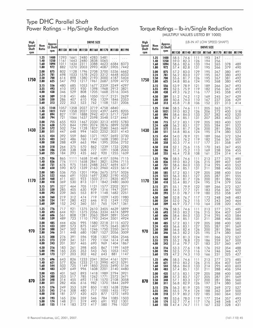
© Rexnord Industries, LLC, 2001, 2007. (161-110) 45
Type DHC Parallel ShaftPower Ratings – Hp/Single Reduction Torque Ratings – lb-in/Single Reduction
(MULTIPLY VALUES LISTED BY 1000)
HighSpeedShaftrpm
NomRatio
ApproxLS Shaft
rpm
(LB-IN AT LOW SPEED SHAFT)
DRIVE SIZE
M1130 M1140 M1150 M1160 M1170 M1180 M1190
1750
1.25 1400 58.5 74.6 111 193 247 . . . . . .1.40 1250 59.0 82.3 126 194 256 . . . . . .1.60 1094 58.6 82.6 133 194 265 378 4891.80 972 57.4 82.8 131 195 266 379 490
2.00 875 57.2 83.0 129 195 267 380 4912.24 781 56.2 83.0 127 195 267 380 4922.50 700 55.6 81.7 126 195 267 381 4922.80 625 54.8 80.6 124 195 268 380 493
3.15 556 53.9 78.9 121 189 266 367 4933.55 493 52.5 75.9 119 182 256 367 4934.00 438 49.3 76.2 116 177 245 358 493
4.50 389 51.2 74.2 112 169 245 347 4295.00 350 50.6 74.0 110 167 237 336 4295.60 313 45.8 71.8 106 152 221 313 414
1430
1.25 1144 58.5 74.6 111 205 263 375 . . .1.40 1021 59.0 83.2 126 206 272 400 5181.60 894 58.6 84.0 133 207 282 402 5201.80 794 57.4 85.1 131 207 283 403 521
2.00 715 57.2 83.1 129 205 283 400 5222.24 638 56.2 83.1 127 205 284 391 5222.50 572 55.6 81.7 126 200 281 386 5232.80 511 54.8 80.6 124 195 274 380 523
3.15 454 54.0 78.9 121 189 266 372 5243.55 403 53.5 76.2 119 182 256 367 5004.00 358 50.3 77.4 117 177 251 358 497
4.50 318 52.1 75.6 115 170 245 347 4555.00 286 51.3 75.2 113 169 238 336 4555.60 255 46.4 72.8 108 161 224 314 414
1170
1.25 936 58.5 74.6 111 213 277 375 4851.40 836 59.0 83.2 126 215 289 407 5491.60 731 58.6 84.0 133 214 295 403 5521.80 650 57.4 85.1 131 211 288 406 553
2.00 585 57.2 83.1 129 205 288 400 5542.24 522 56.3 83.1 127 205 287 391 5552.50 468 55.6 81.7 126 200 281 386 5552.80 418 55.4 80.7 124 195 274 379 556
3.15 371 55.1 79.9 122 189 266 372 5273.55 330 54.5 77.7 121 183 256 367 5004.00 293 51.0 78.7 119 180 253 358 497
4.50 260 52.8 76.7 117 173 248 348 4835.00 234 52.0 76.2 115 172 243 340 4645.60 209 46.9 73.7 110 164 228 320 420
970
1.25 776 58.5 74.6 111 213 277 375 4851.40 693 59.0 83.2 126 215 304 407 5491.60 606 58.6 84.0 133 214 295 403 5841.80 539 57.4 85.1 131 211 288 406 585
2.00 485 57.2 83.1 129 205 288 400 5822.24 433 56.6 83.1 127 205 287 391 5692.50 388 56.6 82.4 126 200 281 386 5602.80 346 56.3 82.2 125 195 274 380 560
3.15 308 55.9 81.3 124 191 266 372 5273.55 273 55.2 78.8 123 186 259 367 5004.00 243 51.6 79.7 121 183 257 360 497
4.50 216 53.3 77.6 118 176 252 354 4885.00 194 52.5 77.0 116 174 246 346 4725.60 173 47.2 74.3 110 166 231 325 427
870
1.25 696 58.5 74.6 111 213 277 375 4851.40 621 59.0 83.2 126 215 304 407 5491.60 544 58.6 84.0 133 214 295 403 6031.80 483 57.4 85.1 131 211 288 406 594
2.00 435 57.5 83.1 129 205 288 400 5822.24 388 57.3 83.7 127 205 287 391 5692.50 348 57.1 83.3 127 200 281 386 5602.80 311 56.8 82.9 126 197 274 380 560
3.15 276 56.3 81.9 125 193 269 372 5273.55 245 55.5 79.4 124 188 262 369 5004.00 218 51.9 80.2 122 185 260 364 502
4.50 193 53.6 78.0 119 177 254 357 4935.00 174 52.7 77.4 117 176 248 348 4775.60 155 47.4 74.7 111 167 232 328 431
HighSpeedShaftrpm
NomRatio
ApproxLS Shaft
rpm
DRIVE SIZE
M1130 M1140 M1150 M1160 M1170 M1180 M1190
1750
1.25 1400 1293 1661 2480 4283 5481 . . . . . .1.40 1250 1161 1643 2480 3838 5065 . . . . . .1.60 1094 1011 1434 2311 3388 4623 6584 83731.80 972 882 1270 2003 2993 4087 5905 7442
2.00 875 802 1128 1796 2708 3700 5336 66622.24 781 698 1033 1578 2423 3312 4648 60332.50 700 614 898 1380 2193 3000 4187 54042.80 625 547 793 1217 1961 2687 3709 4772
3.15 556 480 685 1053 1677 2359 3249 42973.55 493 410 593 930 1398 1968 2912 38214.00 438 346 529 808 1205 1668 2516 3345
4.50 389 318 451 686 1050 1517 2121 26295.00 350 286 407 610 936 1329 1846 23535.60 313 222 353 523 762 1108 1531 2006
1430
1.25 1144 1057 1358 2027 3719 4758 6840 . . .1.40 1021 949 1358 2027 3332 4397 6495 82051.60 894 827 1191 1888 2942 4013 5717 72691.80 794 721 1066 1637 2598 3548 5127 6461
2.00 715 655 923 1467 2330 3213 4592 57832.24 638 570 844 1290 2074 2876 3899 52382.50 572 502 734 1128 1837 2580 3465 46912.80 511 447 648 994 1603 2252 3031 4143
3.15 454 392 559 860 1371 1927 2692 37303.55 403 342 486 760 1142 1608 2380 31674.00 358 288 439 663 984 1395 2056 2752
4.50 318 264 375 570 862 1239 1733 22835.00 286 238 338 508 777 1091 1508 20435.60 255 184 293 435 662 920 1255 1639
1170
1.25 936 865 1111 1658 3148 4107 5596 71151.40 836 776 1111 1658 2841 3821 5396 71151.60 731 676 975 1545 2488 3437 4694 63171.80 650 590 872 1339 2163 2960 4223 5614
2.00 585 536 755 1201 1906 2675 3757 50262.24 522 466 691 1055 1697 2382 3190 45522.50 468 411 601 923 1503 2111 2835 40772.80 418 369 530 813 1311 1842 2480 3600
3.15 371 327 464 705 1121 1577 2202 30713.55 330 285 405 630 939 1316 1947 25914.00 293 239 365 553 819 1148 1682 2251
4.50 260 219 312 474 719 1029 1420 19805.00 234 197 280 422 646 910 1249 17025.60 209 152 242 360 551 765 1047 1361
970
1.25 776 717 921 1375 2610 3405 4639 58991.40 693 644 921 1375 2356 3334 4474 58991.60 606 561 808 1281 2063 2849 3891 55401.80 539 489 723 1110 1793 2454 3501 4924
2.00 485 444 626 995 1580 2218 3115 43722.24 433 389 573 875 1407 1975 2645 38702.50 388 347 502 765 1246 1750 2350 34102.80 346 311 448 680 1087 1527 2056 3009
3.15 308 276 391 596 938 1307 1826 25463.55 273 239 341 531 792 1104 1614 21484.00 243 201 307 465 690 969 1404 1867
4.50 216 183 261 398 605 867 1199 16595.00 194 165 235 353 543 765 1053 14375.60 173 127 203 302 462 643 881 1147
870
1.25 696 643 826 1233 2341 3054 4161 52911.40 621 577 826 1233 2113 2990 4012 52911.60 544 503 725 1149 1850 2555 3490 51341.80 483 439 649 996 1608 2201 3140 4480
2.00 435 401 562 893 1418 1989 2794 39212.24 388 353 517 785 1262 1771 2372 34712.50 348 314 455 692 1118 1570 2108 30582.80 311 282 406 616 982 1370 1844 2699
3.15 276 249 353 539 850 1183 1638 22843.55 245 216 308 480 717 1000 1455 19274.00 218 181 277 420 623 877 1272 1693
4.50 193 165 236 359 546 784 1085 15035.00 174 148 211 319 490 691 952 13015.60 155 114 183 272 417 580 796 1037
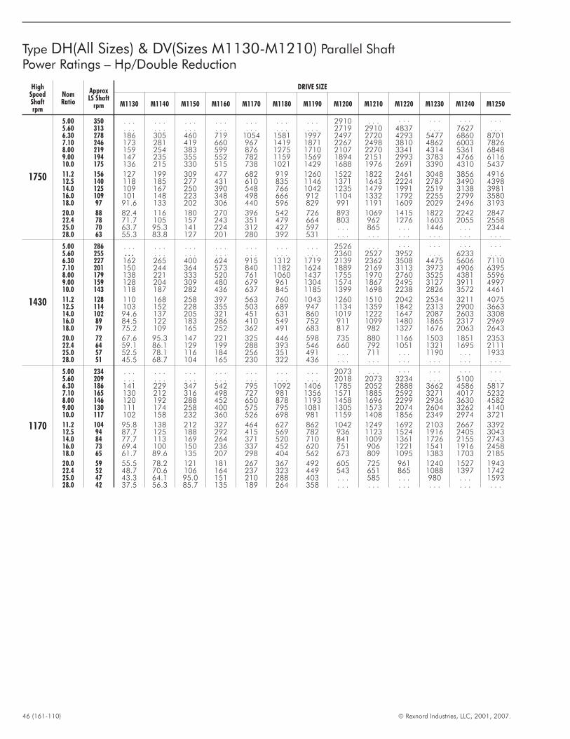
46 (161-110) © Rexnord Industries, LLC, 2001, 2007.
Type DH(All Sizes) & DV(Sizes M1130-M1210) Parallel ShaftPower Ratings – Hp/Double Reduction
HighSpeedShaftrpm
NomRatio
ApproxLS Shaft
rpm
DRIVE SIZE
M1130 M1140 M1150 M1160 M1170 M1180 M1190 M1200 M1210 M1220 M1230 M1240 M1250
1750
5.00 350 . . . . . . . . . . . . . . . . . . . . . 2910 . . . . . . . . . . . . . . .5.60 313 . . . . . . . . . . . . . . . . . . . . . 2719 2910 4837 . . . 7627 . . .6.30 278 186 305 460 719 1054 1581 1997 2497 2720 4293 5477 6860 87017.10 246 173 281 419 660 967 1419 1871 2267 2498 3810 4862 6003 78268.00 219 159 254 383 599 876 1275 1710 2107 2270 3341 4314 5361 68489.00 194 147 235 355 552 782 1159 1569 1894 2151 2993 3783 4766 611610.0 175 136 215 330 515 738 1021 1429 1688 1976 2691 3390 4310 5437
11.2 156 127 199 309 477 682 919 1260 1522 1822 2461 3048 3856 491612.5 140 118 185 277 431 610 835 1146 1371 1643 2224 2787 3490 439814.0 125 109 167 250 390 548 766 1042 1235 1479 1991 2519 3138 398116.0 109 101 148 223 348 498 666 912 1104 1332 1792 2255 2799 358018.0 97 91.6 133 202 306 440 596 829 991 1191 1609 2029 2496 3193
20.0 88 82.4 116 180 270 396 542 726 893 1069 1415 1822 2242 284722.4 78 71.7 105 157 243 351 479 664 803 962 1276 1603 2055 255825.0 70 63.7 95.3 141 224 312 427 597 . . . 865 . . . 1446 . . . 234428.0 63 55.3 83.8 127 201 280 392 531 . . . . . . . . . . . . . . . . . .
1430
5.00 286 . . . . . . . . . . . . . . . . . . . . . 2526 . . . . . . . . . . . . . . .5.60 255 . . . . . . . . . . . . . . . . . . . . . 2360 2527 3952 . . . 6233 . . .6.30 227 162 265 400 624 915 1312 1719 2139 2362 3508 4475 5606 71107.10 201 150 244 364 573 840 1182 1624 1889 2169 3113 3973 4906 63958.00 179 138 221 333 520 761 1060 1437 1755 1970 2760 3525 4381 55969.00 159 128 204 309 480 679 961 1304 1574 1867 2495 3127 3911 499710.0 143 118 187 282 436 637 845 1185 1399 1698 2238 2826 3572 4461
11.2 128 110 168 258 397 563 760 1043 1260 1510 2042 2534 3211 407512.5 114 103 152 228 355 503 689 947 1134 1359 1842 2313 2900 366314.0 102 94.6 137 205 321 451 631 860 1019 1222 1647 2087 2603 330816.0 89 84.5 122 183 286 410 549 752 911 1099 1480 1865 2317 296918.0 79 75.2 109 165 252 362 491 683 817 982 1327 1676 2063 2643
20.0 72 67.6 95.3 147 221 325 446 598 735 880 1166 1503 1851 235322.4 64 59.1 86.1 129 199 288 393 546 660 792 1051 1321 1695 211125.0 57 52.5 78.1 116 184 256 351 491 . . . 711 . . . 1190 . . . 193328.0 51 45.5 68.7 104 165 230 322 436 . . . . . . . . . . . . . . . . . .
1170
5.00 234 . . . . . . . . . . . . . . . . . . . . . 2073 . . . . . . . . . . . . . . .5.60 209 . . . . . . . . . . . . . . . . . . . . . 2018 2073 3234 . . . 5100 . . .6.30 186 141 229 347 542 795 1092 1406 1785 2052 2888 3662 4586 58177.10 165 130 212 316 498 727 981 1356 1571 1885 2592 3271 4017 52328.00 146 120 192 288 452 650 878 1193 1458 1696 2299 2936 3630 45829.00 130 111 174 258 400 575 795 1081 1305 1573 2074 2604 3262 414010.0 117 102 158 232 360 526 698 981 1159 1408 1856 2349 2974 3721
11.2 104 95.8 138 212 327 464 627 862 1042 1249 1692 2103 2667 339212.5 94 87.7 125 188 292 415 569 782 936 1123 1524 1916 2405 304314.0 84 77.7 113 169 264 371 520 710 841 1009 1361 1726 2155 274316.0 73 69.4 100 150 236 337 452 620 751 906 1221 1541 1916 245818.0 65 61.7 89.6 135 207 298 404 562 673 809 1095 1383 1703 2185
20.0 59 55.5 78.2 121 181 267 367 492 605 725 961 1240 1527 194322.4 52 48.7 70.6 106 164 237 323 449 543 651 865 1088 1397 174225.0 47 43.3 64.1 95.0 151 210 288 403 . . . 585 . . . 980 . . . 159328.0 42 37.5 56.3 85.7 135 189 264 358 . . . . . . . . . . . . . . . . . .
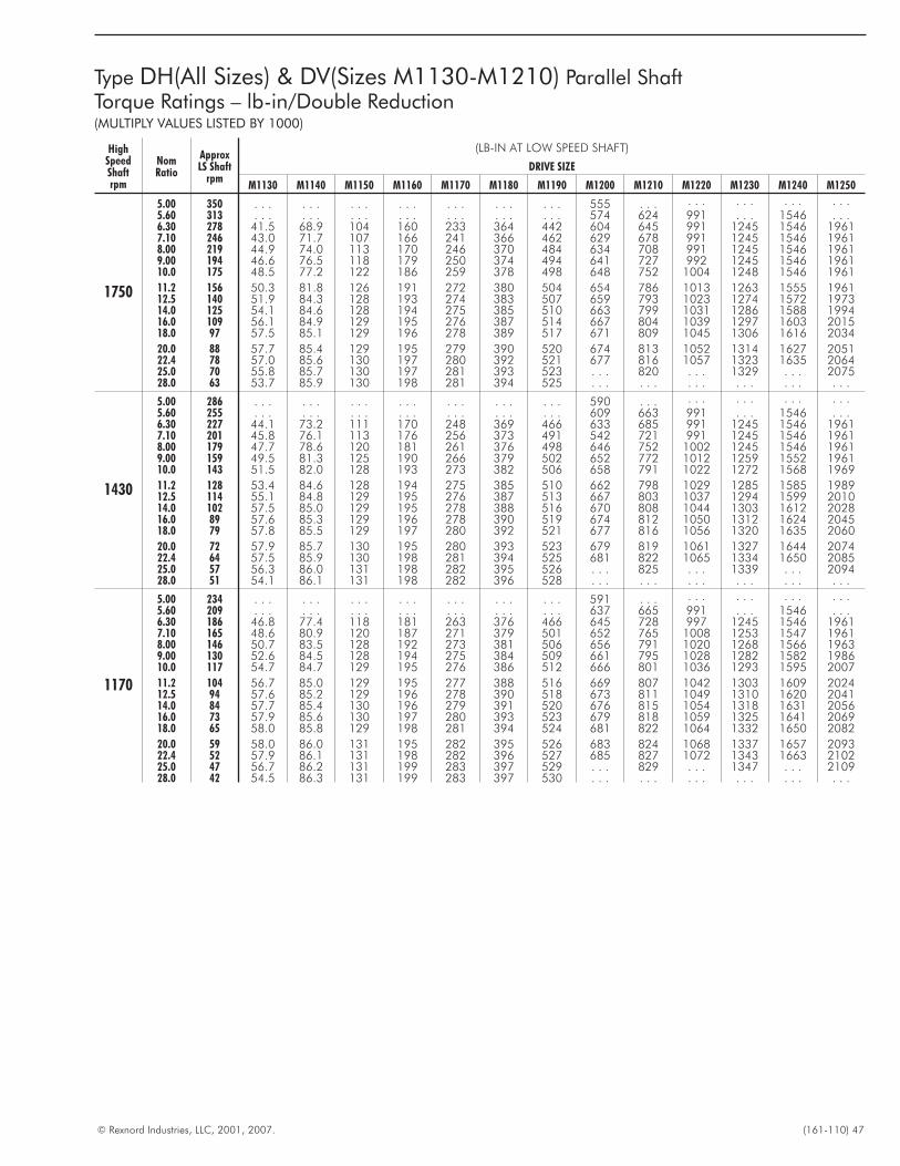
© Rexnord Industries, LLC, 2001, 2007. (161-110) 47
Type DH(All Sizes) & DV(Sizes M1130-M1210) Parallel ShaftTorque Ratings – lb-in/Double Reduction(MULTIPLY VALUES LISTED BY 1000)
HighSpeedShaftrpm
NomRatio
ApproxLS Shaft
rpm
(LB-IN AT LOW SPEED SHAFT)
DRIVE SIZE
M1130 M1140 M1150 M1160 M1170 M1180 M1190 M1200 M1210 M1220 M1230 M1240 M1250
1750
5.00 350 . . . . . . . . . . . . . . . . . . . . . 555 . . . . . . . . . . . . . . .5.60 313 . . . . . . . . . . . . . . . . . . . . . 574 624 991 . . . 1546 . . .6.30 278 41.5 68.9 104 160 233 364 442 604 645 991 1245 1546 19617.10 246 43.0 71.7 107 166 241 366 462 629 678 991 1245 1546 19618.00 219 44.9 74.0 113 170 246 370 484 634 708 991 1245 1546 19619.00 194 46.6 76.5 118 179 250 374 494 641 727 992 1245 1546 196110.0 175 48.5 77.2 122 186 259 378 498 648 752 1004 1248 1546 1961
11.2 156 50.3 81.8 126 191 272 380 504 654 786 1013 1263 1555 196112.5 140 51.9 84.3 128 193 274 383 507 659 793 1023 1274 1572 197314.0 125 54.1 84.6 128 194 275 385 510 663 799 1031 1286 1588 199416.0 109 56.1 84.9 129 195 276 387 514 667 804 1039 1297 1603 201518.0 97 57.5 85.1 129 196 278 389 517 671 809 1045 1306 1616 2034
20.0 88 57.7 85.4 129 195 279 390 520 674 813 1052 1314 1627 205122.4 78 57.0 85.6 130 197 280 392 521 677 816 1057 1323 1635 206425.0 70 55.8 85.7 130 197 281 393 523 . . . 820 . . . 1329 . . . 207528.0 63 53.7 85.9 130 198 281 394 525 . . . . . . . . . . . . . . . . . .
1430
5.00 286 . . . . . . . . . . . . . . . . . . . . . 590 . . . . . . . . . . . . . . .5.60 255 . . . . . . . . . . . . . . . . . . . . . 609 663 991 . . . 1546 . . .6.30 227 44.1 73.2 111 170 248 369 466 633 685 991 1245 1546 19617.10 201 45.8 76.1 113 176 256 373 491 542 721 991 1245 1546 19618.00 179 47.7 78.6 120 181 261 376 498 646 752 1002 1245 1546 19619.00 159 49.5 81.3 125 190 266 379 502 652 772 1012 1259 1552 196110.0 143 51.5 82.0 128 193 273 382 506 658 791 1022 1272 1568 1969
11.2 128 53.4 84.6 128 194 275 385 510 662 798 1029 1285 1585 198912.5 114 55.1 84.8 129 195 276 387 513 667 803 1037 1294 1599 201014.0 102 57.5 85.0 129 195 278 388 516 670 808 1044 1303 1612 202816.0 89 57.6 85.3 129 196 278 390 519 674 812 1050 1312 1624 204518.0 79 57.8 85.5 129 197 280 392 521 677 816 1056 1320 1635 2060
20.0 72 57.9 85.7 130 195 280 393 523 679 819 1061 1327 1644 207422.4 64 57.5 85.9 130 198 281 394 525 681 822 1065 1334 1650 208525.0 57 56.3 86.0 131 198 282 395 526 . . . 825 . . . 1339 . . . 209428.0 51 54.1 86.1 131 198 282 396 528 . . . . . . . . . . . . . . . . . .
1170
5.00 234 . . . . . . . . . . . . . . . . . . . . . 591 . . . . . . . . . . . . . . .5.60 209 . . . . . . . . . . . . . . . . . . . . . 637 665 991 . . . 1546 . . .6.30 186 46.8 77.4 118 181 263 376 466 645 728 997 1245 1546 19617.10 165 48.6 80.9 120 187 271 379 501 652 765 1008 1253 1547 19618.00 146 50.7 83.5 128 192 273 381 506 656 791 1020 1268 1566 19639.00 130 52.6 84.5 128 194 275 384 509 661 795 1028 1282 1582 198610.0 117 54.7 84.7 129 195 276 386 512 666 801 1036 1293 1595 2007
11.2 104 56.7 85.0 129 195 277 388 516 669 807 1042 1303 1609 202412.5 94 57.6 85.2 129 196 278 390 518 673 811 1049 1310 1620 204114.0 84 57.7 85.4 130 196 279 391 520 676 815 1054 1318 1631 205616.0 73 57.9 85.6 130 197 280 393 523 679 818 1059 1325 1641 206918.0 65 58.0 85.8 129 198 281 394 524 681 822 1064 1332 1650 2082
20.0 59 58.0 86.0 131 195 282 395 526 683 824 1068 1337 1657 209322.4 52 57.9 86.1 131 198 282 396 527 685 827 1072 1343 1663 210225.0 47 56.7 86.2 131 199 283 397 529 . . . 829 . . . 1347 . . . 210928.0 42 54.5 86.3 131 199 283 397 530 . . . . . . . . . . . . . . . . . .
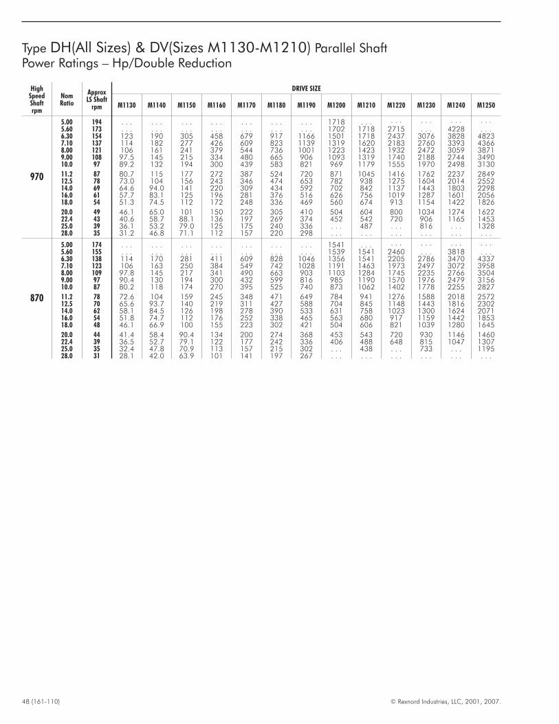
48 (161-110) © Rexnord Industries, LLC, 2001, 2007.
HighSpeedShaftrpm
NomRatio
ApproxLS Shaft
rpm
DRIVE SIZE
M1130 M1140 M1150 M1160 M1170 M1180 M1190 M1200 M1210 M1220 M1230 M1240 M1250
970
5.00 194 . . . . . . . . . . . . . . . . . . . . . 1718 . . . . . . . . . . . . . . .5.60 173 . . . . . . . . . . . . . . . . . . . . . 1702 1718 2715 . . . 4228 . . .6.30 154 123 190 305 458 679 917 1166 1501 1718 2437 3076 3828 48237.10 137 114 182 277 426 609 823 1139 1319 1620 2183 2760 3393 43668.00 121 106 161 241 379 544 736 1001 1223 1423 1932 2472 3059 38719.00 108 97.5 145 215 334 480 665 906 1093 1319 1740 2188 2744 349010.0 97 89.2 132 194 300 439 583 821 969 1179 1555 1970 2498 3130
11.2 87 80.7 115 177 272 387 524 720 871 1045 1416 1762 2237 284912.5 78 73.0 104 156 243 346 474 653 782 938 1275 1604 2014 255214.0 69 64.6 94.0 141 220 309 434 592 702 842 1137 1443 1803 229816.0 61 57.7 83.1 125 196 281 376 516 626 756 1019 1287 1601 205618.0 54 51.3 74.5 112 172 248 336 469 560 674 913 1154 1422 1826
20.0 49 46.1 65.0 101 150 222 305 410 504 604 800 1034 1274 162222.4 43 40.6 58.7 88.1 136 197 269 374 452 542 720 906 1165 145325.0 39 36.1 53.2 79.0 125 175 240 336 . . . 487 . . . 816 . . . 132828.0 35 31.2 46.8 71.1 112 157 220 298 . . . . . . . . . . . . . . . . . .
870
5.00 174 . . . . . . . . . . . . . . . . . . . . . 1541 . . . . . . . . . . . . . . .5.60 155 . . . . . . . . . . . . . . . . . . . . . 1539 1541 2460 . . . 3818 . . .6.30 138 114 170 281 411 609 828 1046 1356 1541 2205 2786 3470 43377.10 123 106 163 250 384 549 742 1028 1191 1463 1973 2497 3072 39588.00 109 97.8 145 217 341 490 663 903 1103 1284 1745 2235 2766 35049.00 97 90.4 130 194 300 432 599 816 985 1190 1570 1976 2479 315610.0 87 80.2 118 174 270 395 525 740 873 1062 1402 1778 2255 2827
11.2 78 72.6 104 159 245 348 471 649 784 941 1276 1588 2018 257212.5 70 65.6 93.7 140 219 311 427 588 704 845 1148 1443 1816 230214.0 62 58.1 84.5 126 198 278 390 533 631 758 1023 1300 1624 207116.0 54 51.8 74.7 112 176 252 338 465 563 680 917 1159 1442 185318.0 48 46.1 66.9 100 155 223 302 421 504 606 821 1039 1280 1645
20.0 44 41.4 58.4 90.4 134 200 274 368 453 543 720 930 1146 146022.4 39 36.5 52.7 79.1 122 177 242 336 406 488 648 815 1047 130725.0 35 32.4 47.8 70.9 113 157 215 302 . . . 438 . . . 733 . . . 119528.0 31 28.1 42.0 63.9 101 141 197 267 . . . . . . . . . . . . . . . . . .
Type DH(All Sizes) & DV(Sizes M1130-M1210) Parallel ShaftPower Ratings – Hp/Double Reduction
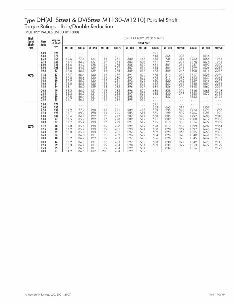
© Rexnord Industries, LLC, 2001, 2007. (161-110) 49
Type DH(All Sizes) & DV(Sizes M1130-M1210) Parallel ShaftTorque Ratings – lb-in/Double Reduction(MULTIPLY VALUES LISTED BY 1000)
HighSpeedShaftrpm
NomRatio
ApproxLS Shaft
rpm
(LB-IN AT LOW SPEED SHAFT)
DRIVE SIZE
M1130 M1140 M1150 M1160 M1170 M1180 M1190 M1200 M1210 M1220 M1230 M1240 M1250
970
5.00 194 . . . . . . . . . . . . . . . . . . . . . 591 . . . . . . . . . . . . . . .5.60 173 . . . . . . . . . . . . . . . . . . . . . 648 665 1003 . . . 1546 . . .6.30 154 49.6 77.4 124 184 271 380 466 655 735 1014 1262 1556 19617.10 137 51.4 83.7 127 193 274 383 507 661 794 1024 1275 1576 19748.00 121 53.6 84.7 128 194 275 385 512 664 801 1034 1287 1592 20009.00 108 55.6 84.9 129 195 277 387 514 668 804 1041 1299 1606 201910.0 97 57.6 85.1 129 196 278 389 517 672 809 1047 1308 1616 2037
11.2 87 57.7 85.4 130 196 279 391 520 675 814 1052 1317 1628 205012.5 78 57.8 85.6 130 197 280 392 522 678 817 1057 1323 1637 206514.0 69 57.9 85.7 130 197 281 393 523 680 820 1062 1329 1646 207716.0 61 58.0 85.9 130 198 281 395 526 682 823 1066 1335 1654 208818.0 54 58.1 86.0 129 198 282 396 527 684 826 1070 1340 1662 2099
20.0 49 58.2 86.2 131 195 283 396 529 686 828 1074 1345 1668 210822.4 43 58.3 86.3 131 199 283 397 529 688 830 1077 1350 1672 211625.0 39 57.0 86.4 131 199 284 398 531 . . . 832 . . . 1353 . . . 212128.0 35 54.7 86.5 131 199 284 399 532 . . . . . . . . . . . . . . . . . .
870
5.00 174 . . . . . . . . . . . . . . . . . . . . . 591 . . . . . . . . . . . . . . .5.60 155 . . . . . . . . . . . . . . . . . . . . . 653 665 1014 . . . 1557 . . .6.30 138 51.2 77.4 128 184 271 383 466 659 735 1023 1274 1573 19667.10 123 53.1 83.7 128 194 275 385 511 665 799 1032 1286 1591 19958.00 109 55.4 84.9 129 195 277 387 514 668 805 1040 1297 1605 20189.00 97 57.5 85.2 129 196 278 389 517 671 809 1047 1308 1617 203610.0 87 57.7 85.4 130 196 279 391 519 675 813 1053 1316 1627 2052
11.2 78 57.8 85.6 130 197 280 392 522 678 817 1057 1323 1637 206412.5 70 57.9 85.7 130 197 281 393 524 680 820 1062 1327 1645 207714.0 62 58.0 85.9 130 198 281 394 525 682 823 1066 1335 1653 208716.0 54 58.1 86.0 131 198 282 396 527 684 826 1070 1340 1661 209718.0 48 58.2 86.2 129 199 283 397 528 686 828 1073 1345 1667 2107
20.0 44 58.2 86.3 131 195 283 397 530 688 830 1077 1349 1673 211522.4 39 58.3 86.4 131 199 284 398 531 689 832 1079 1353 1677 212225.0 35 57.1 86.5 131 199 284 399 531 . . . 834 . . . 1356 . . . 212728.0 31 54.9 86.5 132 200 284 399 532 . . . . . . . . . . . . . . . . . .
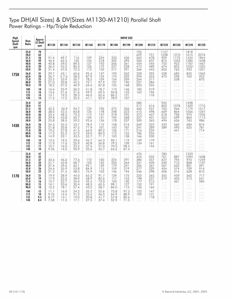
50 (161-110) © Rexnord Industries, LLC, 2001, 2007.
HighSpeedShaftrpm
NomRatio
ApproxLS Shaft
rpm
DRIVE SIZE
M1130 M1140 M1150 M1160 M1170 M1180 M1190 M1200 M1210 M1220 M1230 M1240 M1250
1750
25.0 70 . . . . . . . . . . . . . . . . . . . . . 705 . . . 1157 . . . 1818 . . .28.0 63 . . . . . . . . . . . . . . . . . . . . . 629 751 1038 1310 1615 207631.5 56 51.6 69.7 116 159 234 333 436 563 678 929 1175 1434 184436.0 49 46.4 65.3 102 154 218 302 395 506 607 815 1052 1285 163840.0 44 40.8 59.0 89.5 137 192 266 361 454 545 753 923 1187 146745.0 39 36.3 53.5 80.3 126 172 237 328 412 489 674 852 1052 135550.0 35 31.4 47.0 72.3 113 155 217 291 366 443 603 763 933 1201
56.0 31 29.7 43.1 65.6 95.4 137 193 262 328 395 528 683 835 106563.0 28 26.7 3 7.6 58.0 87.9 124 175 229 294 353 475 598 762 95371.0 25 23.5 33.9 50.7 78.2 109 154 209 264 317 . . . 538 . . . 87080.0 22 21.0 30.8 45.5 72.1 97.9 137 190 227 284 . . . . . . . . . . . .90.0 19 18.2 27.0 40.9 64.5 87.8 125 168 203 245 . . . . . . . . . . . .
100 18 16.6 23.9 36.2 51.8 78.7 110 146 182 219 . . . . . . . . . . . .112 16 14.6 21.6 31.6 49.9 69.5 96.8 133 163 196 . . . . . . . . . . . .125 14 13.1 19.5 28.3 46.0 62.4 86.2 121 . . . 176 . . . . . . . . . . . .140 13 11.3 17.2 25.5 41.1 55.9 78.9 107 . . . . . . . . . . . . . . . . . .
1430
25.0 57 . . . . . . . . . . . . . . . . . . . . . 580 . . . 952 . . . 1498 . . .28.0 51 . . . . . . . . . . . . . . . . . . . . . 517 614 853 1078 1329 171031.5 45 42.2 56.9 94.7 133 196 273 356 462 557 763 966 1179 151736.0 40 38.0 53.5 83.8 126 178 248 323 415 498 669 864 1056 134740.0 36 33.4 48.3 73.3 112 157 218 295 373 447 618 758 975 120545.0 32 29.8 43.8 65.7 104 141 194 268 337 401 553 699 864 111350.0 29 25.8 38.5 59.2 92.6 126 178 237 300 363 494 626 765 986
56.0 26 24.3 35.3 53.7 78.9 112 158 214 269 323 433 560 684 87463.0 23 21.8 30.8 47.5 71.9 101 143 187 241 289 389 490 625 78171.0 20 19.2 27.8 41.5 64.0 89.2 126 171 216 259 . . . 441 . . . 71480.0 18 17.2 25.2 37.2 59.0 80.0 112 155 186 233 . . . . . . . . . . . .90.0 16 14.9 22.1 33.5 52.7 71.7 103 138 166 200 . . . . . . . . . . . .
100 14 13.5 19.5 29.6 42.7 64.3 90.1 119 149 179 . . . . . . . . . . . .112 13 11.9 17.6 25.9 40.8 56.8 79.2 109 134 161 . . . . . . . . . . . .125 11 10.7 16.0 23.2 37.6 51.0 70.5 98.5 . . . 144 . . . . . . . . . . . .140 10 9.26 14.0 20.9 33.6 45.7 64.6 87.4 . . . . . . . . . . . . . . . . . .
1170
25.0 47 . . . . . . . . . . . . . . . . . . . . . 476 . . . 783 . . . 1233 . . .28.0 42 . . . . . . . . . . . . . . . . . . . . . 424 502 701 887 1094 140831.5 37 34.6 46.6 77.6 110 160 224 291 380 457 627 794 970 124936.0 33 31.1 43.8 68.7 103 145 203 264 341 409 549 710 868 110740.0 29 27.4 39.6 60.1 92.1 129 179 241 306 367 507 622 801 99145.0 26 24.4 35.9 53.8 84.9 115 159 219 277 329 454 574 709 91450.0 23 21.2 31.5 48.5 75.9 103 146 194 246 298 406 514 628 810
56.0 21 19.9 28.9 44.0 65.2 91.7 129 175 220 265 355 459 562 71763.0 19 17.9 25.2 38.9 58.9 82.6 117 153 198 237 319 402 513 64171.0 16 15.7 22.7 34.0 52.4 73.0 103 140 177 213 . . . 361 . . . 58580.0 15 14.1 20.6 30.4 48.3 65.5 98.1 127 152 191 . . . . . . . . . . . .90.0 13 12.2 18.1 27.4 43.2 58.7 84.0 113 136 164 . . . . . . . . . . . .
100 12 11.1 16.0 24.2 35.2 52.6 73.8 97.3 122 147 . . . . . . . . . . . .112 10 9.76 14.4 21.2 33.4 46.5 64.9 88.9 109 131 . . . . . . . . . . . .125 9.4 8.77 13.1 19.0 30.8 41.7 57.8 80.6 . . . 118 . . . . . . . . . . . .140 8.4 7.58 11.5 17.1 27.5 37.4 52.9 71.5 . . . . . . . . . . . . . . . . . .
Type DH(All Sizes) & DV(Sizes M1130-M1210) Parallel ShaftPower Ratings – Hp/Triple Reduction
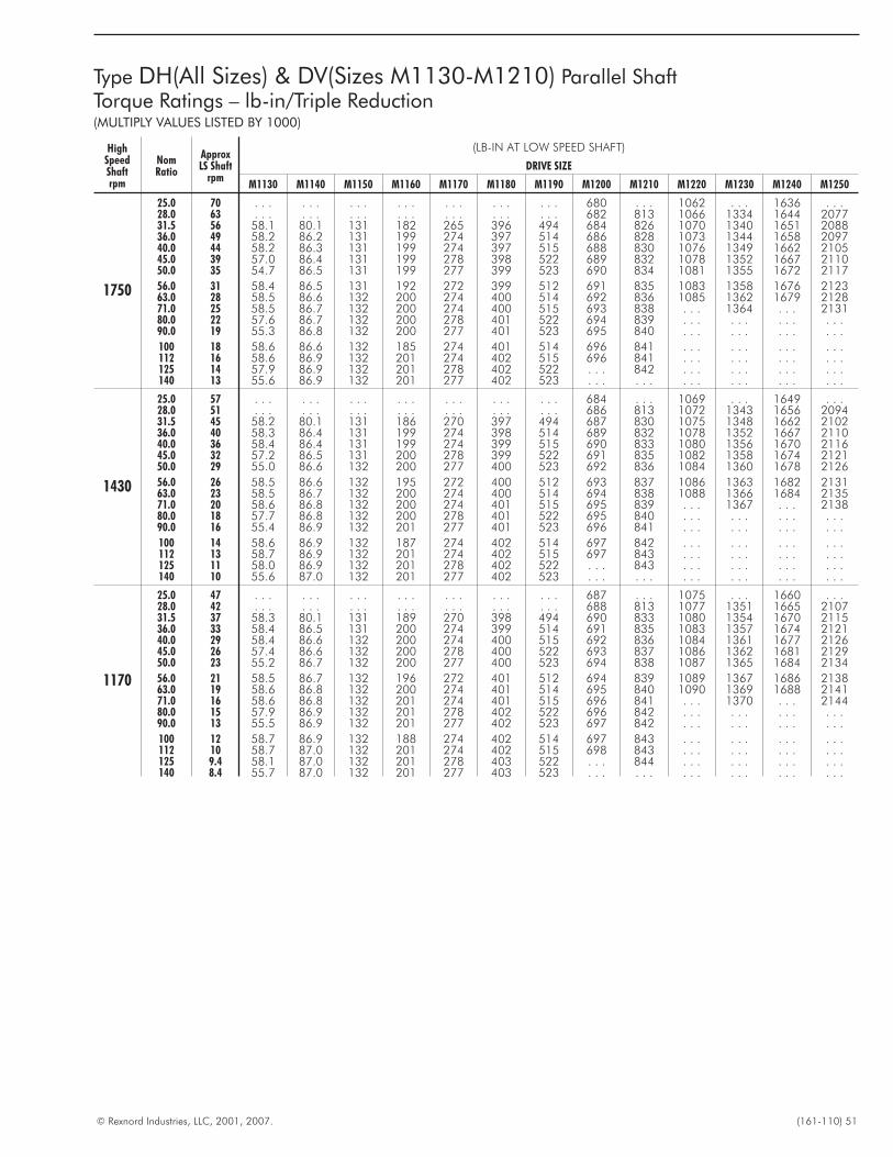
© Rexnord Industries, LLC, 2001, 2007. (161-110) 51
Type DH(All Sizes) & DV(Sizes M1130-M1210) Parallel ShaftTorque Ratings – lb-in/Triple Reduction(MULTIPLY VALUES LISTED BY 1000)
HighSpeedShaftrpm
NomRatio
ApproxLS Shaft
rpm
(LB-IN AT LOW SPEED SHAFT)
DRIVE SIZE
M1130 M1140 M1150 M1160 M1170 M1180 M1190 M1200 M1210 M1220 M1230 M1240 M1250
1750
25.0 70 . . . . . . . . . . . . . . . . . . . . . 680 . . . 1062 . . . 1636 . . .28.0 63 . . . . . . . . . . . . . . . . . . . . . 682 813 1066 1334 1644 207731.5 56 58.1 80.1 131 182 265 396 494 684 826 1070 1340 1651 208836.0 49 58.2 86.2 131 199 274 397 514 686 828 1073 1344 1658 209740.0 44 58.2 86.3 131 199 274 397 515 688 830 1076 1349 1662 210545.0 39 57.0 86.4 131 199 278 398 522 689 832 1078 1352 1667 211050.0 35 54.7 86.5 131 199 277 399 523 690 834 1081 1355 1672 2117
56.0 31 58.4 86.5 131 192 272 399 512 691 835 1083 1358 1676 212363.0 28 58.5 86.6 132 200 274 400 514 692 836 1085 1362 1679 212871.0 25 58.5 86.7 132 200 274 400 515 693 838 . . . 1364 . . . 213180.0 22 57.6 86.7 132 200 278 401 522 694 839 . . . . . . . . . . . .90.0 19 55.3 86.8 132 200 277 401 523 695 840 . . . . . . . . . . . .
100 18 58.6 86.6 132 185 274 401 514 696 841 . . . . . . . . . . . .112 16 58.6 86.9 132 201 274 402 515 696 841 . . . . . . . . . . . .125 14 57.9 86.9 132 201 278 402 522 . . . 842 . . . . . . . . . . . .140 13 55.6 86.9 132 201 277 402 523 . . . . . . . . . . . . . . . . . .
1430
25.0 57 . . . . . . . . . . . . . . . . . . . . . 684 . . . 1069 . . . 1649 . . .28.0 51 . . . . . . . . . . . . . . . . . . . . . 686 813 1072 1343 1656 209431.5 45 58.2 80.1 131 186 270 397 494 687 830 1075 1348 1662 210236.0 40 58.3 86.4 131 199 274 398 514 689 832 1078 1352 1667 211040.0 36 58.4 86.4 131 199 274 399 515 690 833 1080 1356 1670 211645.0 32 57.2 86.5 131 200 278 399 522 691 835 1082 1358 1674 212150.0 29 55.0 86.6 132 200 277 400 523 692 836 1084 1360 1678 2126
56.0 26 58.5 86.6 132 195 272 400 512 693 837 1086 1363 1682 213163.0 23 58.5 86.7 132 200 274 400 514 694 838 1088 1366 1684 213571.0 20 58.6 86.8 132 200 274 401 515 695 839 . . . 1367 . . . 213880.0 18 57.7 86.8 132 200 278 401 522 695 840 . . . . . . . . . . . .90.0 16 55.4 86.9 132 201 277 401 523 696 841 . . . . . . . . . . . .
100 14 58.6 86.9 132 187 274 402 514 697 842 . . . . . . . . . . . .112 13 58.7 86.9 132 201 274 402 515 697 843 . . . . . . . . . . . .125 11 58.0 86.9 132 201 278 402 522 . . . 843 . . . . . . . . . . . .140 10 55.6 87.0 132 201 277 402 523 . . . . . . . . . . . . . . . . . .
1170
25.0 47 . . . . . . . . . . . . . . . . . . . . . 687 . . . 1075 . . . 1660 . . .28.0 42 . . . . . . . . . . . . . . . . . . . . . 688 813 1077 1351 1665 210731.5 37 58.3 80.1 131 189 270 398 494 690 833 1080 1354 1670 211536.0 33 58.4 86.5 131 200 274 399 514 691 835 1083 1357 1674 212140.0 29 58.4 86.6 132 200 274 400 515 692 836 1084 1361 1677 212645.0 26 57.4 86.6 132 200 278 400 522 693 837 1086 1362 1681 212950.0 23 55.2 86.7 132 200 277 400 523 694 838 1087 1365 1684 2134
56.0 21 58.5 86.7 132 196 272 401 512 694 839 1089 1367 1686 213863.0 19 58.6 86.8 132 200 274 401 514 695 840 1090 1369 1688 214171.0 16 58.6 86.8 132 201 274 401 515 696 841 . . . 1370 . . . 214480.0 15 57.9 86.9 132 201 278 402 522 696 842 . . . . . . . . . . . .90.0 13 55.5 86.9 132 201 277 402 523 697 842 . . . . . . . . . . . .
100 12 58.7 86.9 132 188 274 402 514 697 843 . . . . . . . . . . . .112 10 58.7 87.0 132 201 274 402 515 698 843 . . . . . . . . . . . .125 9.4 58.1 87.0 132 201 278 403 522 . . . 844 . . . . . . . . . . . .140 8.4 55.7 87.0 132 201 277 403 523 . . . . . . . . . . . . . . . . . .
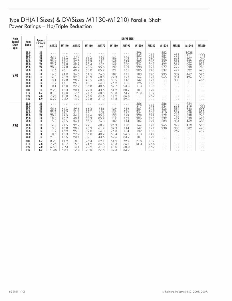
52 (161-110) © Rexnord Industries, LLC, 2001, 2007.
Type DH(All Sizes) & DV(Sizes M1130-M1210) Parallel ShaftPower Ratings – Hp/Triple Reduction
HighSpeedShaftrpm
NomRatio
ApproxLS Shaft
rpm
DRIVE SIZE
M1130 M1140 M1150 M1160 M1170 M1180 M1190 M1200 M1210 M1220 M1230 M1240 M1250
970
25.0 39 . . . . . . . . . . . . . . . . . . . . . 396 . . . 652 . . . 1028 . . .25.0 35 . . . . . . . . . . . . . . . . . . . . . 353 416 584 738 911 117331.5 31 28.7 38.6 64.5 92.6 133 186 242 316 380 522 661 807 104036.0 27 25.8 36.4 57.0 85.9 121 169 219 283 340 457 591 722 92240.0 24 22.7 32.8 49.9 76.4 107 149 200 254 305 422 517 666 82445.0 22 20.3 29.8 44.7 70.5 95.6 132 182 230 273 377 477 590 76050.0 19 17.6 26.1 40.2 63.0 85.7 121 161 205 248 337 427 522 673
56.0 17 16.5 24.0 36.5 54.5 76.0 107 145 183 220 295 382 467 59663.0 15 14.8 20.9 32.3 48.9 68.5 97.3 127 164 197 265 334 426 53371.0 14 13.1 19.8 28.2 43.5 60.5 85.5 116 147 177 . . . 300 . . . 48680.0 12 11.7 17.1 25.3 40.1 54.3 76.2 105 126 158 . . . . . . . . . . . .90.0 11 10.1 15.0 22.7 35.8 48.6 69.7 93.3 113 136 . . . . . . . . . . . .
100 10 9.20 13.3 20.1 29.3 43.6 61.2 80.7 101 122 . . . . . . . . . . . .112 8.7 8.10 12.0 17.6 27.7 38.5 53.8 73.7 90.8 109 . . . . . . . . . . . .125 7.8 7.28 10.8 15.7 25.5 34.6 47.9 66.8 . . . 97.7 . . . . . . . . . . . .140 6.9 6.29 9.52 14.2 22.8 31.0 43.8 59.3 . . . . . . . . . . . . . . . . . .
870
25.0 35 . . . . . . . . . . . . . . . . . . . . . 356 . . . 586 . . . 924 . . .28.0 31 . . . . . . . . . . . . . . . . . . . . . 317 373 524 663 819 105531.5 28 25.8 34.6 57.9 83.5 119 167 217 284 341 469 594 725 93536.0 24 23.2 32.7 51.2 77.1 108 152 197 254 305 410 531 648 82840.0 22 20.4 29.5 44.8 68.6 95.6 133 179 228 274 379 465 598 74045.0 19 18.3 26.7 40.1 63.3 85.7 119 163 206 246 339 429 530 68350.0 17 15.8 23.5 36.1 56.5 76.8 109 144 184 222 303 384 469 605
56.0 16 14.8 21.5 32.7 49.1 68.2 96.3 130 164 198 265 343 419 53563.0 14 13.3 18.8 28.9 43.9 61.4 87.3 114 147 177 238 300 382 47871.0 12 11.7 16.9 25.3 39.0 54.3 76.8 104 132 158 . . . 269 . . . 43780.0 11 10.5 15.3 22.7 36.0 48.7 68.4 94.3 113 142 . . . . . . . . . . . .90.0 10 9.10 13.5 20.4 32.1 43.6 62.6 83.7 101 122 . . . . . . . . . . . .
100 8.7 8.25 11.9 18.0 26.4 39.1 54.9 72.4 90.9 109 . . . . . . . . . . . .112 7.8 7.26 10.7 15.8 24.9 34.5 48.3 66.1 81.4 97.6 . . . . . . . . . . . .125 7.0 6.53 9.73 14.1 22.9 31.0 43.0 60.0 . . . 87.7 . . . . . . . . . . . .140 6.2 5. 65 8.54 12.7 20.5 27.8 39.3 53.2 . . . . . . . . . . . . . . . . . .
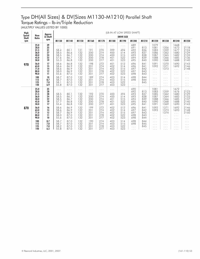
© Rexnord Industries, LLC, 2001, 2007. (161-110) 53
Type DH(All Sizes) & DV(Sizes M1130-M1210) Parallel ShaftTorque Ratings – lb-in/Triple Reduction(MULTIPLY VALUES LISTED BY 1000)
HighSpeedShaftrpm
NomRatio
ApproxLS Shaft
rpm
(LB-IN AT LOW SPEED SHAFT)
DRIVE SIZE
M1130 M1140 M1150 M1160 M1170 M1180 M1190 M1200 M1210 M1220 M1230 M1240 M1250
970
25.0 39 . . . . . . . . . . . . . . . . . . . . . 689 . . . 1079 . . . 1668 . . .28.0 35 . . . . . . . . . . . . . . . . . . . . . 691 813 1081 1356 1673 211831.5 31 58.4 80.1 131 191 270 399 494 692 836 1083 1359 1677 212436.0 27 58.5 86.6 132 200 274 400 514 693 837 1086 1362 1680 212940.0 24 58.5 86.7 132 200 274 400 515 693 838 1087 1365 1682 213345.0 22 57.6 86.7 132 200 278 401 522 694 839 1088 1366 1685 213650.0 19 55.3 86.8 132 200 277 401 523 695 840 1090 1368 1688 2140
56.0 17 58.6 86.8 132 198 272 401 512 696 841 1091 1370 1690 214363.0 15 58.6 86.9 132 201 274 402 514 696 841 1092 1371 1692 214671.0 14 58.6 86.9 132 201 274 402 515 697 842 . . . 1373 . . . 214880.0 12 58.0 86.9 132 201 278 402 522 697 843 . . . . . . . . . . . .90.0 11 55.6 87.0 132 201 277 402 523 698 843 . . . . . . . . . . . .
100 10 58.7 87.0 132 189 274 403 514 698 844 . . . . . . . . . . . .112 8.7 58.7 87.0 132 201 274 403 515 698 844 . . . . . . . . . . . .125 7.8 58.1 87.0 132 201 278 403 522 . . . 845 . . . . . . . . . . . .140 6.9 55.8 87.0 132 201 277 403 523 . . . . . . . . . . . . . . . . . .
870
25.0 35 . . . . . . . . . . . . . . . . . . . . . 690 . . . 1081 . . . 1672 . . .28.0 28 . . . . . . . . . . . . . . . . . . . . . 692 813 1083 1359 1676 212331.5 28 58.5 80.1 132 192 270 400 494 693 837 1085 1362 1680 212936.0 24 58.5 86.7 132 200 274 400 514 693 838 1087 1364 1683 213340.0 22 58.5 86.7 132 200 274 401 515 694 839 1088 1366 1685 213745.0 19 57.7 86.8 132 200 278 401 522 695 840 1090 1368 1688 214050.0 17 55.4 86.8 132 200 277 401 523 695 841 1091 1369 1690 2143
56.0 16 58.6 86.9 132 199 272 402 512 696 841 1092 1371 1692 214663.0 14 58.6 86.9 132 201 274 402 514 697 842 1093 1373 1693 214871.0 12 58.7 86.9 132 201 274 402 515 697 843 . . . 1374 . . . 215080.0 11 58.0 87.0 132 201 278 402 522 698 843 . . . . . . . . . . . .90.0 10 55.6 87.0 132 201 277 402 523 698 844 . . . . . . . . . . . .
100 8.7 58.7 87.0 132 190 274 403 514 698 844 . . . . . . . . . . . .112 7.8 58.7 87.0 132 201 274 403 515 698 845 . . . . . . . . . . . .125 7.0 58.2 87.0 132 201 278 403 522 . . . 845 . . . . . . . . . . . .140 6.2 55.8 87.0 132 201 277 403 523 . . . . . . . . . . . . . . . . . .
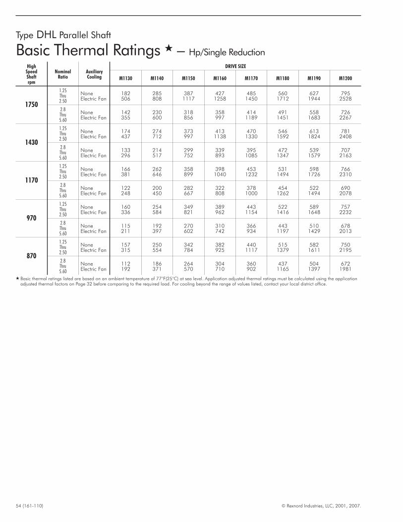
54 (161-110) © Rexnord Industries, LLC, 2001, 2007.
Type DHL Parallel Shaft
Basic Thermal Ratings � – Hp/Single Reduction
HighSpeedShaftrpm
NominalRatio
AuxiliaryCooling
DRIVE SIZE
M1130 M1140 M1150 M1160 M1170 M1180 M1190 M1200
1750
1.25Thru2.50
NoneElectric Fan
182506
285808
3871117
4271258
4851450
5601712
6271944
7952528
2.8Thru5.60
NoneElectric Fan
142355
230600
318856
358997
4141189
4911451
5581683
7262267
1430
1.25Thru2.50
NoneElectric Fan
174437
274712
373997
4131138
4701330
5461592
6131824
7812408
2.8Thru5.60
NoneElectric Fan
133296
214517
299752
339893
3951085
4721347
5391579
7072163
1170
1.25Thru2.50
NoneElectric Fan
166381
262646
358899
3981040
4531232
5311494
5981726
7662310
2.8Thru5.60
NoneElectric Fan
122248
200450
282667
322808
3781000
4541262
5221494
6902078
970
1.25Thru2.50
NoneElectric Fan
160336
254584
349821
389962
4431154
5221416
5891648
7572232
2.8Thru5.60
NoneElectric Fan
115211
192397
270602
310742
366934
4431197
5101429
6782013
870
1.25Thru2.50
NoneElectric Fan
157315
250554
342784
382925
4401117
5151379
5821611
7502195
2.8Thru5.60
NoneElectric Fan
112192
186371
264570
304710
360902
4371165
5041397
6721981
� Basic thermal ratings listed are based on an ambient temperature of 77°F(25°C) at sea level. Application adjusted thermal ratings must be calculated using the applicationadjusted thermal factors on Page 32 before comparing to the required load. For cooling beyond the range of values listed, contact your local district office.
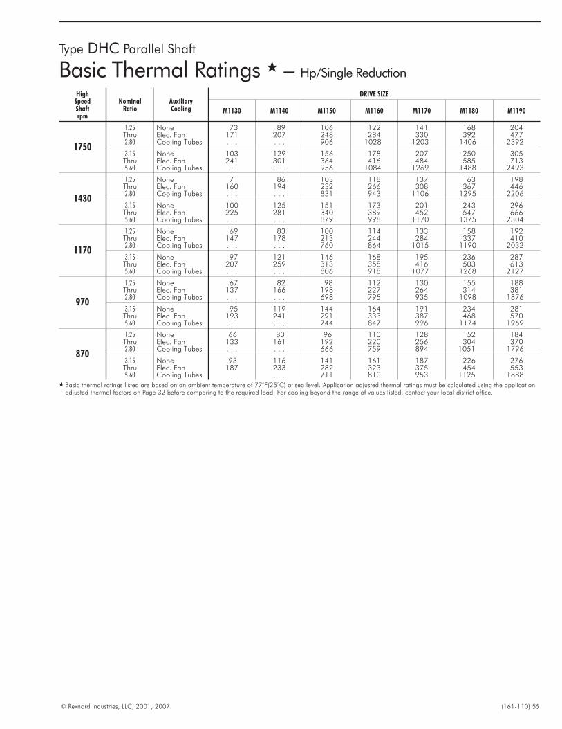
© Rexnord Industries, LLC, 2001, 2007. (161-110) 55
HighSpeedShaftrpm
NominalRatio
AuxiliaryCooling
DRIVE SIZE
M1130 M1140 M1150 M1160 M1170 M1180 M1190
1750
1.25 None 73 89 106 122 141 168 204Thru Elec. Fan 171 207 248 284 330 392 4772.80 Cooling Tubes . . . . . . 906 1028 1203 1406 2392
3.15 None 103 129 156 178 207 250 305Thru Elec. Fan 241 301 364 416 484 585 7135.60 Cooling Tubes . . . . . . 956 1084 1269 1488 2493
1430
1.25 None 71 86 103 118 137 163 198Thru Elec. Fan 160 194 232 266 308 367 4462.80 Cooling Tubes . . . . . . 831 943 1106 1295 2206
3.15 None 100 125 151 173 201 243 296Thru Elec. Fan 225 281 340 389 452 547 6665.60 Cooling Tubes . . . . . . 879 998 1170 1375 2304
1170
1.25 None 69 83 100 114 133 158 192Thru Elec. Fan 147 178 213 244 284 337 4102.80 Cooling Tubes . . . . . . 760 864 1015 1190 2032
3.15 None 97 121 146 168 195 236 287Thru Elec. Fan 207 259 313 358 416 503 6135.60 Cooling Tubes . . . . . . 806 918 1077 1268 2127
970
1.25 None 67 82 98 112 130 155 188Thru Elec. Fan 137 166 198 227 264 314 3812.80 Cooling Tubes . . . . . . 698 795 935 1098 1876
3.15 None 95 119 144 164 191 234 281Thru Elec. Fan 193 241 291 333 387 468 5705.60 Cooling Tubes . . . . . . 744 847 996 1174 1969
870
1.25 None 66 80 96 110 128 152 184Thru Elec. Fan 133 161 192 220 256 304 3702.80 Cooling Tubes . . . . . . 666 759 894 1051 1796
3.15 None 93 116 141 161 187 226 276Thru Elec. Fan 187 233 282 323 375 454 5535.60 Cooling Tubes . . . . . . 711 810 953 1125 1888
� Basic thermal ratings listed are based on an ambient temperature of 77°F(25°C) at sea level. Application adjusted thermal ratings must be calculated using the applicationadjusted thermal factors on Page 32 before comparing to the required load. For cooling beyond the range of values listed, contact your local district office.
Type DHC Parallel Shaft
Basic Thermal Ratings � – Hp/Single Reduction
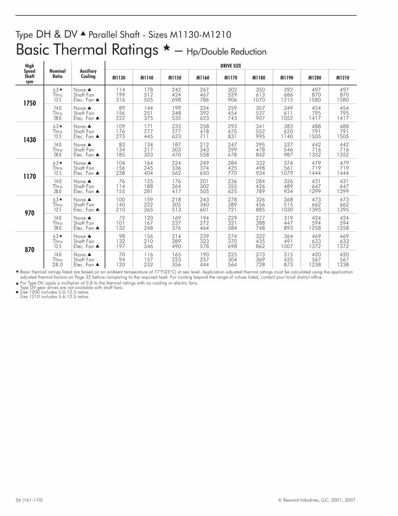
56 (161-110) © Rexnord Industries, LLC, 2001, 2007.
Type DH & DV � Parallel Shaft - Sizes M1130-M1210
Basic Thermal Ratings � – Hp/Double Reduction
HighSpeedShaftrpm
NominalRatio
AuxiliaryCooling
DRIVE SIZE
M1130 M1140 M1150 M1160 M1170 M1180 M1190 M1200 M1210
1750
6.3 � None � 114 178 242 267 302 350 392 497 497Thru Shaft Fan 199 312 424 467 529 613 686 870 87012.5 Elec. Fan � 316 505 698 786 906 1070 1215 1580 1580
14.0 None � 89 144 199 224 259 307 349 454 454Thru Shaft Fan 156 251 348 392 454 537 611 795 79528.0 Elec. Fan � 222 375 535 623 743 907 1052 1417 1417
1430
6.3 � None � 109 171 233 258 293 341 383 488 488Thru Shaft Fan 176 277 377 418 475 552 620 791 79112.5 Elec. Fan � 273 445 623 711 831 995 1140 1505 1505
14.0 None � 83 134 187 212 247 295 337 442 442Thru Shaft Fan 134 217 303 343 399 478 546 716 71628.0 Elec. Fan � 185 323 470 558 678 842 987 1352 1352
1170
6.3 � None � 104 164 224 249 284 332 374 479 479Thru Shaft Fan 156 245 336 374 425 498 561 719 71912.5 Elec. Fan � 238 404 562 650 770 934 1079 1444 1444
14.0 None � 76 125 176 201 236 284 326 431 431Thru Shaft Fan 114 188 264 302 355 426 489 647 64728.0 Elec. Fan � 155 281 417 505 625 789 934 1299 1299
970
6.3 � None � 100 159 218 243 278 326 368 473 473Thru Shaft Fan 140 222 305 340 389 456 515 662 66212.5 Elec. Fan � 210 365 513 601 721 885 1030 1395 1395
14.0 None � 72 120 169 194 229 277 319 424 424Thru Shaft Fan 101 167 237 272 321 388 447 594 59428.0 Elec. Fan � 132 248 376 464 584 748 893 1258 1258
870
6.3 � None � 98 156 214 239 274 322 364 469 469Thru Shaft Fan 132 210 289 323 370 435 491 633 63312.5 Elec. Fan � 197 346 490 578 698 862 1007 1372 1372
14.0 None � 70 116 165 190 225 273 315 420 420Thru Shaft Fan 94 157 223 257 304 369 425 567 56728.0 Elec. Fan � 120 232 356 444 564 728 873 1238 1238
� Basic thermal ratings listed are based on an ambient temperature of 77°F(25°C) at sea level. Application adjusted thermal ratings must be calculated using the applicationadjusted thermal factors on Page 32 before comparing to the required load. For cooling beyond the range of values listed, contact your local district office.
� For Type DV, apply a multiplier of 0.8 to the thermal ratings with no cooling or electric fans.Type DV gear drives are not available with shaft fans.
� Size 1200 includes 5.0-12.5 ratios.Size 1210 includes 5.6-12.5 ratios.
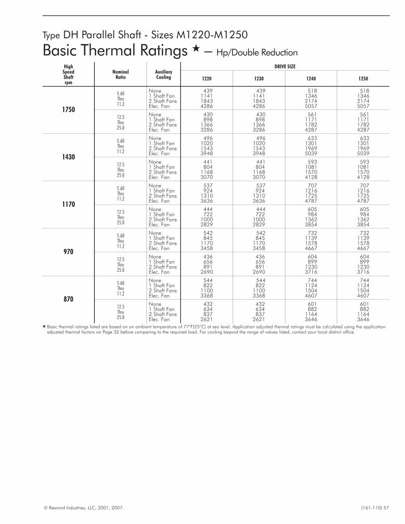
© Rexnord Industries, LLC, 2001, 2007. (161-110) 57
Type DH Parallel Shaft - Sizes M1220-M1250
Basic Thermal Ratings � – Hp/Double Reduction
HighSpeedShaftrpm
NominalRatio
AuxiliaryCooling
DRIVE SIZE
1220 1230 1240 1250
1750
5.60Thru11.2
None 439 439 518 5181 Shaft Fan 1141 1141 1346 13462 Shaft Fans 1843 1843 2174 2174Elec. Fan 4286 4286 5057 5057
12.5Thru25.0
None 430 430 561 5611 Shaft Fan 898 898 1171 11712 Shaft Fans 1366 1366 1782 1782Elec. Fan 3286 3286 4287 4287
1430
5.60Thru11.2
None 496 496 633 6331 Shaft Fan 1020 1020 1301 13012 Shaft Fans 1543 1543 1969 1969Elec. Fan 3948 3948 5039 5039
12.5Thru25.0
None 441 441 593 5931 Shaft Fan 804 804 1081 10812 Shaft Fans 1168 1168 1570 1570Elec. Fan 3070 3070 4128 4128
1170
5.60Thru11.2
None 537 537 707 7071 Shaft Fan 924 924 1216 12162 Shaft Fans 1310 1310 1725 1725Elec. Fan 3636 3636 4787 4787
12.5Thru25.0
None 444 444 605 6051 Shaft Fan 722 722 984 9842 Shaft Fans 1000 1000 1362 1362Elec. Fan 2829 2829 3854 3854
970
5.60Thru11.2
None 542 542 732 7321 Shaft Fan 845 845 1139 11392 Shaft Fans 1170 1170 1578 1578Elec. Fan 3458 3458 4667 4667
12.5Thru25.0
None 436 436 604 6041 Shaft Fan 656 656 899 8992 Shaft Fans 891 891 1230 1230Elec. Fan 2690 2690 3716 3716
870
5.60Thru11.2
None 544 544 744 7441 Shaft Fan 822 822 1124 11242 Shaft Fans 1100 1100 1504 1504Elec. Fan 3368 3368 4607 4607
12.5Thru25.0
None 432 432 601 6011 Shaft Fan 634 634 882 8822 Shaft Fans 837 837 1164 1164Elec. Fan 2621 2621 3646 3646
� Basic thermal ratings listed are based on an ambient temperature of 77°F(25°C) at sea level. Application adjusted thermal ratings must be calculated using the applicationadjusted thermal factors on Page 32 before comparing to the required load. For cooling beyond the range of values listed, contact your local district office.
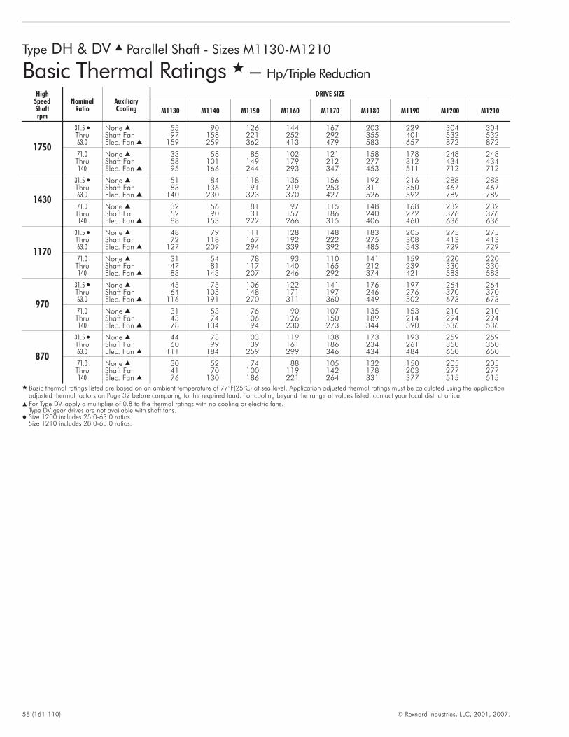
58 (161-110) © Rexnord Industries, LLC, 2001, 2007.
Type DH & DV � Parallel Shaft - Sizes M1130-M1210
Basic Thermal Ratings � – Hp/Triple Reduction
HighSpeedShaftrpm
NominalRatio
AuxiliaryCooling
DRIVE SIZE
M1130 M1140 M1150 M1160 M1170 M1180 M1190 M1200 M1210
1750
31.5 � None � 55 90 126 144 167 203 229 304 304Thru Shaft Fan 97 158 221 252 292 355 401 532 53263.0 Elec. Fan � 159 259 362 413 479 583 657 872 872
71.0 None � 33 58 85 102 121 158 178 248 248Thru Shaft Fan 58 101 149 179 212 277 312 434 434140 Elec. Fan � 95 166 244 293 347 453 511 712 712
1430
31.5 � None � 51 84 118 135 156 192 216 288 288Thru Shaft Fan 83 136 191 219 253 311 350 467 46763.0 Elec. Fan � 140 230 323 370 427 526 592 789 789
71.0 None � 32 56 81 97 115 148 168 232 232Thru Shaft Fan 52 90 131 157 186 240 272 376 376140 Elec. Fan � 88 153 222 266 315 406 460 636 636
1170
31.5 � None � 48 79 111 128 148 183 205 275 275Thru Shaft Fan 72 118 167 192 222 275 308 413 41363.0 Elec. Fan � 127 209 294 339 392 485 543 729 729
71.0 None � 31 54 78 93 110 141 159 220 220Thru Shaft Fan 47 81 117 140 165 212 239 330 330140 Elec. Fan � 83 143 207 246 292 374 421 583 583
970
31.5 � None � 45 75 106 122 141 176 197 264 264Thru Shaft Fan 64 105 148 171 197 246 276 370 37063.0 Elec. Fan � 116 191 270 311 360 449 502 673 673
71.0 None � 31 53 76 90 107 135 153 210 210Thru Shaft Fan 43 74 106 126 150 189 214 294 294140 Elec. Fan � 78 134 194 230 273 344 390 536 536
870
31.5 � None � 44 73 103 119 138 173 193 259 259Thru Shaft Fan 60 99 139 161 186 234 261 350 35063.0 Elec. Fan � 111 184 259 299 346 434 484 650 650
71.0 None � 30 52 74 88 105 132 150 205 205Thru Shaft Fan 41 70 100 119 142 178 203 277 277140 Elec. Fan � 76 130 186 221 264 331 377 515 515
� Basic thermal ratings listed are based on an ambient temperature of 77°F(25°C) at sea level. Application adjusted thermal ratings must be calculated using the applicationadjusted thermal factors on Page 32 before comparing to the required load. For cooling beyond the range of values listed, contact your local district office.
� For Type DV, apply a multiplier of 0.8 to the thermal ratings with no cooling or electric fans.Type DV gear drives are not available with shaft fans.
� Size 1200 includes 25.0-63.0 ratios.Size 1210 includes 28.0-63.0 ratios.
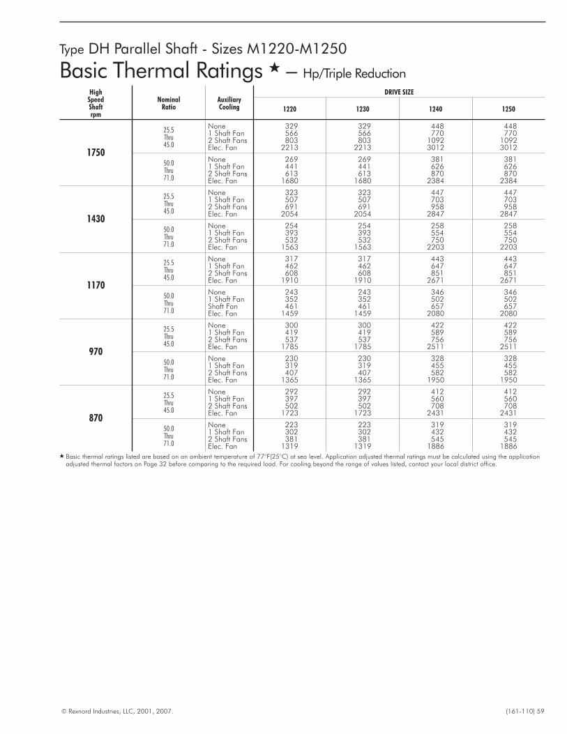
© Rexnord Industries, LLC, 2001, 2007. (161-110) 59
Type DH Parallel Shaft - Sizes M1220-M1250
Basic Thermal Ratings � – Hp/Triple Reduction
HighSpeedShaftrpm
NominalRatio
AuxiliaryCooling
DRIVE SIZE
1220 1230 1240 1250
1750
25.5Thru45.0
None 329 329 448 4481 Shaft Fan 566 566 770 7702 Shaft Fans 803 803 1092 1092Elec. Fan 2213 2213 3012 3012
50.0Thru71.0
None 269 269 381 3811 Shaft Fan 441 441 626 6262 Shaft Fans 613 613 870 870Elec. Fan 1680 1680 2384 2384
1430
25.5Thru45.0
None 323 323 447 4471 Shaft Fan 507 507 703 7032 Shaft Fans 691 691 958 958Elec. Fan 2054 2054 2847 2847
50.0Thru71.0
None 254 254 258 2581 Shaft Fan 393 393 554 5542 Shaft Fans 532 532 750 750Elec. Fan 1563 1563 2203 2203
1170
25.5Thru45.0
None 317 317 443 4431 Shaft Fan 462 462 647 6472 Shaft Fans 608 608 851 851Elec. Fan 1910 1910 2671 2671
50.0Thru71.0
None 243 243 346 3461 Shaft Fan 352 352 502 502Shaft Fan 461 461 657 657Elec. Fan 1459 1459 2080 2080
970
25.5Thru45.0
None 300 300 422 4221 Shaft Fan 419 419 589 5892 Shaft Fans 537 537 756 756Elec. Fan 1785 1785 2511 2511
50.0Thru71.0
None 230 230 328 3281 Shaft Fan 319 319 455 4552 Shaft Fans 407 407 582 582Elec. Fan 1365 1365 1950 1950
870
25.5Thru45.0
None 292 292 412 4121 Shaft Fan 397 397 560 5602 Shaft Fans 502 502 708 708Elec. Fan 1723 1723 2431 2431
50.0Thru71.0
None 223 223 319 3191 Shaft Fan 302 302 432 4322 Shaft Fans 381 381 545 545Elec. Fan 1319 1319 1886 1886
� Basic thermal ratings listed are based on an ambient temperature of 77°F(25°C) at sea level. Application adjusted thermal ratings must be calculated using the applicationadjusted thermal factors on Page 32 before comparing to the required load. For cooling beyond the range of values listed, contact your local district office.
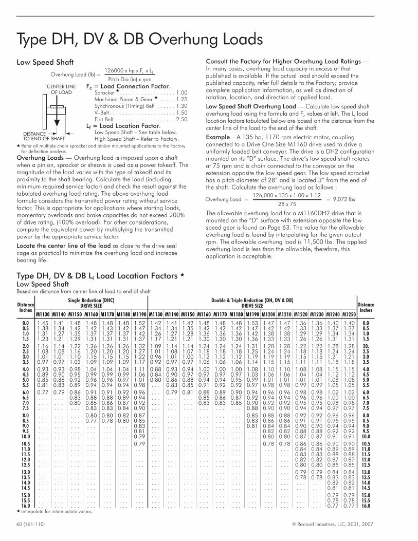
60 (161-110) © Rexnord Industries, LLC, 2001, 2007.
Type DH, DV & DB Overhung Loads
Low Speed Shaft
Overhung Load (lb) =126000 x hp x F x L
Pitch Di
c f
a (in) x rpm
Fc = Load Connection Factor.Sprocket �. . . . . . . . . . . . . . . . . . 1.00Machined Pinion & Gear � . . . . . 1.25Synchronous (Timing) Belt . . . . . . 1.30V–Belt . . . . . . . . . . . . . . . . . . . . . 1.50Flat Belt . . . . . . . . . . . . . . . . . . . 2.50
Lf = Load Location Factor.Low Speed Shaft – See table below.High Speed Shaft – Refer to Factory.
� Refer all multiple chain sprocket and pinion mounted applications to the Factoryfor deflection analysis.
Overhung Loads — Overhung load is imposed upon a shaftwhen a pinion, sprocket or sheave is used as a power takeoff. Themagnitude of the load varies with the type of takeoff and itsproximity to the shaft bearing. Calculate the load (includingminimum required service factor) and check the result against thetabulated overhung load rating. The above overhung loadformula considers the transmitted power rating without servicefactor. This is appropriate for applications where starting loads,momentary overloads and brake capacities do not exceed 200%of drive rating, (100% overload). For other considerations,compute the equivalent power by multiplying the transmittedpower by the appropriate service factor.
Locate the center line of the load as close to the drive sealcage as practical to minimize the overhung load and increasebearing life.
Consult the Factory for Higher Overhung Load Ratings —In many cases, overhung load capacity in excess of thatpublished is available. If the actual load should exceed thepublished capacity, refer full details to the Factory; providecomplete application information, as well as direction ofrotation, location, and direction of applied load.
Low Speed Shaft Overhung Load — Calculate low speed shaftoverhung load using the formula and Fc values at left. The Lf loadlocation factors tabulated below are based on the distance from thecenter line of the load to the end of the shaft.
Example – A 135 hp, 1170 rpm electric motor, couplingconnected to a Drive One Size M1160 drive used to drive auniformly loaded belt conveyor. The drive is a DH2 configurationmounted on its “D” surface. The drive’s low speed shaft rotatesat 75 rpm and is chain connected to the conveyor on theextension opposite the low speed gear. The low speed sprockethas a pitch diameter of 28” and is located 3” from the end ofthe shaft. Calculate the overhung load as follows :
Overhung Load =126,000 x 135 x 1.00 x 1.12
28 x 75= 9,072 lbs
The allowable overhung load for a M1160DH2 drive that ismounted on the “D” surface with extension opposite the lowspeed gear is found on Page 63. The value for the allowableoverhung load is found by interpolating for the given outputrpm. The allowable overhung load is 11,500 lbs. The appliedoverhung load is less than the allowable, therefore, thisapplication is acceptable.
DISTANCETO END OF SHAFT
CENTER LINEOF LOAD
Type DH, DV & DB Lf Load Location Factors �
Low Speed ShaftBased on distance from center line of load to end of shaft
DistanceInches
Single Reduction (DHC)DRIVE SIZE
Double & Triple Reduction (DH, DV & DB)DRIVE SIZE Distance
InchesM1130 M1140 M1150 M1160 M1170 M1180 M1190 M1130 M1140 M1150 M1160 M1170 M1180 M1190 M1200 M1210 M1220 M1230 M1240 M1250
0.0 1.45 1.41 1.48 1.48 1.48 1.48 1.52 1.42 1.41 1.42 1.48 1.48 1.48 1.53 1.47 1.47 1.36 1.36 1.40 1.40 0.00.5 1.38 1.34 1.42 1.42 1.43 1.42 1.47 1.34 1.34 1.35 1.42 1.42 1.42 1.47 1.42 1.42 1.33 1.33 1.37 1.37 0.51.0 1.31 1.27 1.35 1.37 1.37 1.37 1.42 1.26 1.27 1.28 1.36 1.36 1.36 1.42 1.38 1.38 1.29 1.29 1.34 1.34 1.01.5 1.23 1.21 1.29 1.31 1.31 1.31 1.37 1.17 1.21 1.21 1.30 1.30 1.30 1.36 1.33 1.33 1.26 1.26 1.31 1.31 1.5
2.0 1.16 1.14 1.22 1.26 1.26 1.26 1.32 1.09 1.14 1.14 1.24 1.24 1.24 1.31 1.28 1.28 1.22 1.22 1.28 1.28 20.2.5 1.08 1.08 1.16 1.20 1.20 1.20 1.27 1.01 1.08 1.07 1.18 1.18 1.18 1.25 1.24 1.24 1.18 1.18 1.24 1.24 2.53.0 1.01 1.01 1.10 1.15 1.15 1.15 1.22 0.96 1.01 1.00 1.12 1.12 1.12 1.19 1.19 1.19 1.15 1.15 1.21 1.21 3.03.5 0.97 0.97 1.03 1.09 1.09 1.09 1.17 0.92 0.97 0.97 1.06 1.06 1.06 1.14 1.15 1.15 1.11 1.11 1.18 1.18 3.5
4.0 0.93 0.93 0.98 1.04 1.04 1.04 1.11 0.88 0.93 0.94 1.00 1.00 1.00 1.08 1.10 1.10 1.08 1.08 1.15 1.15 4.04.5 0.89 0.90 0.95 0.99 0.99 0.99 1.06 0.84 0.90 0.97 0.97 0.97 0.97 1.03 1.06 1.06 1.04 1.04 1.12 1.12 4.55.0 0.85 0.86 0.92 0.96 0.96 0.97 1.01 0.80 0.86 0.88 0.94 0.94 0.95 0.99 1.01 1.01 1.01 1.01 1.08 1.08 5.05.5 0.81 0.83 0.89 0.94 0.94 0.94 0.98 . . . 0.83 0.85 0.91 0.92 0.92 0.97 0.98 0.98 0.99 0.99 1.05 1.05 5.5
6.0 0.77 0.79 0.86 0.91 0.91 0.92 0.96 . . . 0.79 0.81 0.88 0.89 0.90 0.94 0.96 0.96 0.98 0.98 1.02 1.02 6.06.5 . . . . . . 0.83 0.88 0.88 0.89 0.94 . . . . . . . . . 0.85 0.86 0.87 0.92 0.94 0.94 0.96 0.96 1.00 1.00 6.57.0 . . . . . . 0.80 0.85 0.86 0.87 0.92 . . . . . . . . . 0.83 0.83 0.85 0.90 0.92 0.92 0.95 0.95 0.98 0.98 7.07.5 . . . . . . . . . 0.83 0.83 0.84 0.90 . . . . . . . . . . . . . . . . . . 0.88 0.90 0.90 0.94 0.94 0.97 0.97 7.5
8.0 . . . . . . . . . 0.80 0.80 0.82 0.87 . . . . . . . . . . . . . . . . . . 0.85 0.88 0.88 0.92 0.92 0.96 0.96 8.08.5 . . . . . . . . . 0.77 0.78 0.80 0.85 . . . . . . . . . . . . . . . . . . 0.83 0.86 0.86 0.91 0.91 0.95 0.95 8.59.0 . . . . . . . . . . . . . . . . . . 0.83 . . . . . . . . . . . . . . . . . . 0.81 0.84 0.84 0.90 0.90 0.94 0.94 9.09.5 . . . . . . . . . . . . . . . . . . 0.81 . . . . . . . . . . . . . . . . . . . . . 0.82 0.82 0.88 0.88 0.92 0.92 9.5
10.0 . . . . . . . . . . . . . . . . . . 0.79 . . . . . . . . . . . . . . . . . . . . . 0.80 0.80 0.87 0.87 0.91 0.91 10.0
10.5 . . . . . . . . . . . . . . . . . . 0.79 . . . . . . . . . . . . . . . . . . . . . 0.78 0.78 0.86 0.86 0.90 0.90 10.511.0 . . . . . . . . . . . . . . . . . . . . . . . . . . . . . . . . . . . . . . . . . . . . . . . . 0.84 0.84 0.89 0.89 11.011.5 . . . . . . . . . . . . . . . . . . . . . . . . . . . . . . . . . . . . . . . . . . . . . . . . 0.83 0.83 0.88 0.88 11.512.0 . . . . . . . . . . . . . . . . . . . . . . . . . . . . . . . . . . . . . . . . . . . . . . . . 0.82 0.82 0.87 0.87 12.012.5 . . . . . . . . . . . . . . . . . . . . . . . . . . . . . . . . . . . . . . . . . . . . . . . . 0.80 0.80 0.85 0.85 12.5
13.0 . . . . . . . . . . . . . . . . . . . . . . . . . . . . . . . . . . . . . . . . . . . . . . . . 0.79 0.79 0.84 0.84 13.013.5 . . . . . . . . . . . . . . . . . . . . . . . . . . . . . . . . . . . . . . . . . . . . . . . . 0.78 0.78 0.83 0.83 13.514.0 . . . . . . . . . . . . . . . . . . . . . . . . . . . . . . . . . . . . . . . . . . . . . . . . . . . . . . 0.82 0.82 14.014.5 . . . . . . . . . . . . . . . . . . . . . . . . . . . . . . . . . . . . . . . . . . . . . . . . . . . . . . 0.81 0.81 14.5
15.0 . . . . . . . . . . . . . . . . . . . . . . . . . . . . . . . . . . . . . . . . . . . . . . . . . . . . . . 0.79 0.79 15.015.5 . . . . . . . . . . . . . . . . . . . . . . . . . . . . . . . . . . . . . . . . . . . . . . . . . . . . . . 0.78 0.78 15.516.0 . . . . . . . . . . . . . . . . . . . . . . . . . . . . . . . . . . . . . . . . . . . . . . . . . . . . . . 0.77 0.77 16.0
� Interpolate for intermediate values.

© Rexnord Industries, LLC, 2001, 2007. (161-110) 61
Type DHL Single Reduction & DBL Double Reduction
Low Speed Shaft Overhung Load
REFER TO THE FACTORY
High Speed Shaft Overhung Load - All Reductions
REFER TO THE FACTORY
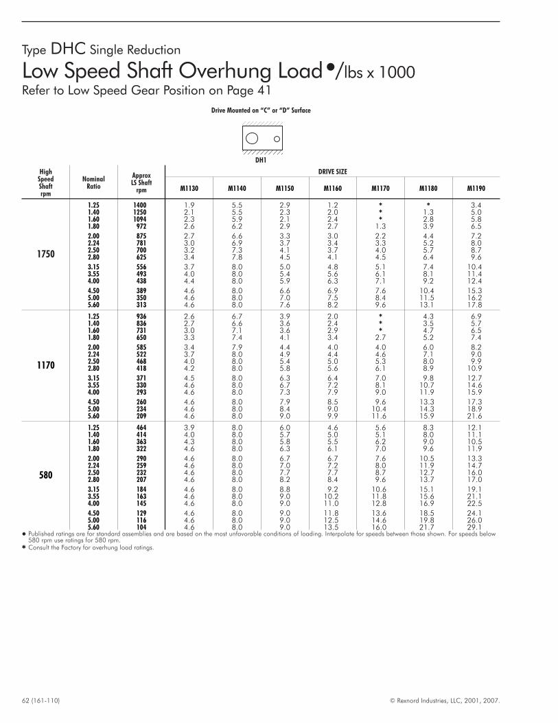
62 (161-110) © Rexnord Industries, LLC, 2001, 2007.
Type DHC Single Reduction
Low Speed Shaft Overhung Load�/lbs x 1000Refer to Low Speed Gear Position on Page 41
Drive Mounted on “C” or “D” Surface
DH1
HighSpeedShaftrpm
NominalRatio
ApproxLS Shaft
rpm
DRIVE SIZE
M1130 M1140 M1150 M1160 M1170 M1180 M1190
1750
1.25 1400 1.9 5.5 2.9 1.2 � � 3.41.40 1250 2.1 5.5 2.3 2.0 � 1.3 5.01.60 1094 2.3 5.9 2.1 2.4 � 2.8 5.81.80 972 2.6 6.2 2.9 2.7 1.3 3.9 6.5
2.00 875 2.7 6.6 3.3 3.0 2.2 4.4 7.22.24 781 3.0 6.9 3.7 3.4 3.3 5.2 8.02.50 700 3.2 7.3 4.1 3.7 4.0 5.7 8.72.80 625 3.4 7.8 4.5 4.1 4.5 6.4 9.6
3.15 556 3.7 8.0 5.0 4.8 5.1 7.4 10.43.55 493 4.0 8.0 5.4 5.6 6.1 8.1 11.44.00 438 4.4 8.0 5.9 6.3 7.1 9.2 12.4
4.50 389 4.6 8.0 6.6 6.9 7.6 10.4 15.35.00 350 4.6 8.0 7.0 7.5 8.4 11.5 16.25.60 313 4.6 8.0 7.6 8.2 9.6 13.1 17.8
1170
1.25 936 2.6 6.7 3.9 2.0 � 4.3 6.91.40 836 2.7 6.6 3.6 2.4 � 3.5 5.71.60 731 3.0 7.1 3.6 2.9 � 4.7 6.51.80 650 3.3 7.4 4.1 3.4 2.7 5.2 7.4
2.00 585 3.4 7.9 4.4 4.0 4.0 6.0 8.22.24 522 3.7 8.0 4.9 4.4 4.6 7.1 9.02.50 468 4.0 8.0 5.4 5.0 5.3 8.0 9.92.80 418 4.2 8.0 5.8 5.6 6.1 8.9 10.9
3.15 371 4.5 8.0 6.3 6.4 7.0 9.8 12.73.55 330 4.6 8.0 6.7 7.2 8.1 10.7 14.64.00 293 4.6 8.0 7.3 7.9 9.0 11.9 15.9
4.50 260 4.6 8.0 7.9 8.5 9.6 13.3 17.35.00 234 4.6 8.0 8.4 9.0 10.4 14.3 18.95.60 209 4.6 8.0 9.0 9.9 11.6 15.9 21.6
580
1.25 464 3.9 8.0 6.0 4.6 5.6 8.3 12.11.40 414 4.0 8.0 5.7 5.0 5.1 8.0 11.11.60 363 4.3 8.0 5.8 5.5 6.2 9.0 10.51.80 322 4.6 8.0 6.3 6.1 7.0 9.6 11.9
2.00 290 4.6 8.0 6.7 6.7 7.6 10.5 13.32.24 259 4.6 8.0 7.0 7.2 8.0 11.9 14.72.50 232 4.6 8.0 7.7 7.7 8.7 12.7 16.02.80 207 4.6 8.0 8.2 8.4 9.6 13.7 17.0
3.15 184 4.6 8.0 8.8 9.2 10.6 15.1 19.13.55 163 4.6 8.0 9.0 10.2 11.8 15.6 21.14.00 145 4.6 8.0 9.0 11.0 12.8 16.9 22.5
4.50 129 4.6 8.0 9.0 11.8 13.6 18.5 24.15.00 116 4.6 8.0 9.0 12.5 14.6 19.8 26.05.60 104 4.6 8.0 9.0 13.5 16.0 21.7 29.1
� Published ratings are for standard assemblies and are based on the most unfavorable conditions of loading. Interpolate for speeds between those shown. For speeds below580 rpm use ratings for 580 rpm.
� Consult the Factory for overhung load ratings.
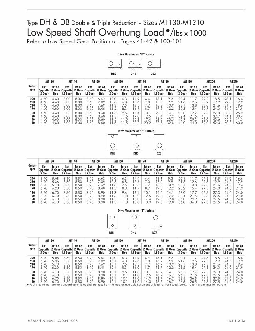
© Rexnord Industries, LLC, 2001, 2007. (161-110) 63
Type DH & DB Double & Triple Reduction - Sizes M1130-M1210
Low Speed Shaft Overhung Load�/lbs x 1000Refer to Low Speed Gear Position on Pages 41-42 & 100-101
Drive Mounted on “D” Surface
DH2 DH3 DB3
Outputrpm
M1130 M1140 M1150 M1160 M1170 M1180 M1190 M1200 M1210
ExtOppositeLS Gear
Ext onLS Gear
Side
ExtOppositeLS Gear
Ext onLS Gear
Side
ExtOppositeLS Gear
Ext onLS Gear
Side
ExtOppositeLS Gear
Ext onLS Gear
Side
ExtOppositeLS Gear
Ext onLS Gear
Side
ExtOppositeLS Gear
Ext onLS Gear
Side
ExtOppositeLS Gear
Ext onLS Gear
Side
ExtOppositeLS Gear
Ext onLS Gear
Side
ExtOppositeLS Gear
Ext onLS Gear
Side
290 4.60 4.60 8.00 8.00 8.60 6.62 10.0 6.3 11.9 6.4 16.1 9.2 20.4 11.7 29.2 18.5 28.1 16.6250 4.60 4.60 8.00 8.00 8.60 7.09 10.6 6.8 12.6 7.0 17.0 9.9 21.6 12.6 30.9 19.9 29.8 17.9210 4.60 4.60 8.00 8.00 8.60 7.69 11.3 7.5 13.5 7.7 18.2 10.9 23.1 13.8 33.0 21.6 31.8 19.6170 4.60 4.60 8.00 8.00 8.60 8.48 11.5 8.3 14.7 8.7 19.8 12.2 25.2 15.4 35.7 24.0 34.5 21.9
130 4.60 4.60 8.00 8.00 8.60 8.60 11.5 9.6 16.4 10.1 22.0 14.1 28.0 17.7 39.5 27.3 38.3 25.290 4.60 4.60 8.00 8.00 8.60 8.60 11.5 11.5 19.0 12.5 25.4 17.2 32.4 21.5 45.3 32.7 44.1 30.450 4.60 4.60 8.00 8.00 8.60 8.60 11.5 11.5 20.2 17.4 32.0 23.5 40.9 29.2 52.0 43.6 55.3 41.310 4.60 4.60 8.00 8.00 8.60 8.60 11.5 11.5 20.2 20.2 32.8 32.8 44.0 44.0 52.0 52.0 60.0 60.0
Drive Mounted on “F” Surface
DH2 DH3 DZ3
Outputrpm
M1130 M1140 M1150 M1160 M1170 M1180 M1190 M1200 M1210
ExtOppositeLS Gear
Ext onLS Gear
Side
ExtOppositeLS Gear
Ext onLS Gear
Side
ExtOppositeLS Gear
Ext onLS Gear
Side
ExtOppositeLS Gear
Ext onLS Gear
Side
ExtOppositeLS Gear
Ext onLS Gear
Side
ExtOppositeLS Gear
Ext onLS Gear
Side
ExtOppositeLS Gear
Ext onLS Gear
Side
ExtOppositeLS Gear
Ext onLS Gear
Side
ExtOppositeLS Gear
Ext onLS Gear
Side
290 6.70 5.08 8.50 8.50 8.90 6.62 10.0 6.3 11.9 6.4 16.1 9.2 20.4 11.7 27.5 18.5 24.0 16.6250 6.70 5.36 8.50 8.50 8.90 7.09 10.6 6.8 12.6 7.0 17.0 9.9 21.6 12.6 27.5 19.9 24.0 17.9210 6.70 5.73 8.50 8.50 8.90 7.69 11.3 7.5 13.5 7.7 18.2 10.9 23.1 13.8 27.5 21.6 24.0 19.6170 6.70 6.20 8.50 8.50 8.90 8.48 11.3 8.3 14.7 8.7 19.0 12.2 25.2 15.4 27.5 24.0 24.0 21.9
130 6.70 6.70 8.50 8.50 8.90 8.90 11.3 9.6 16.4 10.1 19.0 14.1 28.0 17.7 27.5 27.3 24.0 24.090 6.70 6.70 8.50 8.50 8.90 8.90 11.3 11.3 18.0 12.5 19.0 17.2 32.4 21.5 27.5 27.5 24.0 24.050 6.70 6.70 8.50 8.50 8.90 8.90 11.3 11.3 18.0 17.4 19.0 19.0 36.0 29.2 27.5 27.5 24.0 24.010 6.70 6.70 8.50 8.50 8.90 8.90 11.3 11.3 18.0 18.0 19.0 19.0 36.0 36.0 27.5 27.5 24.0 24.0
Drive Mounted on “E” Surface
DH2 DH3 DZ3
Outputrpm
M1130 M1140 M1150 M1160 M1170 M1180 M1190 M1200 M1210
ExtOppositeLS Gear
Ext onLS Gear
Side
ExtOppositeLS Gear
Ext onLS Gear
Side
ExtOppositeLS Gear
Ext onLS Gear
Side
ExtOppositeLS Gear
Ext onLS Gear
Side
ExtOppositeLS Gear
Ext onLS Gear
Side
ExtOppositeLS Gear
Ext onLS Gear
Side
ExtOppositeLS Gear
Ext onLS Gear
Side
ExtOppositeLS Gear
Ext onLS Gear
Side
ExtOppositeLS Gear
Ext onLS Gear
Side
290 6.70 5.08 8.50 8.50 8.90 6.62 10.0 6.3 11.9 6.4 16.1 9.2 20.4 11.7 27.5 18.5 24.0 16.6250 6.70 5.36 8.50 8.50 8.90 7.09 10.1 6.8 12.6 7.0 16.7 9.9 21.6 12.6 27.5 19.9 24.0 17.9210 6.70 5.73 8.50 8.50 8.90 7.69 10.1 7.5 13.5 7.7 16.7 10.9 23.1 13.8 27.5 21.6 24.0 19.6170 6.70 6.20 8.50 8.50 8.90 8.48 10.1 8.3 14.0 8.7 16.7 12.2 25.2 15.4 27.5 24.0 24.0 21.9
130 6.70 6.70 8.50 8.50 8.90 8.90 10.1 9.6 14.0 10.1 16.7 14.1 26.5 17.7 27.5 27.3 24.0 24.090 6.70 6.70 8.50 8.50 8.90 8.90 10.1 10.1 14.0 12.5 16.7 16.7 26.5 21.5 27.5 27.5 24.0 24.050 6.70 6.70 8.50 8.50 8.90 8.90 10.1 10.1 14.0 14.0 16.7 16.7 26.5 26.5 27.5 27.5 24.0 24.010 6.70 6.70 8.50 8.50 8.90 8.90 10.1 10.1 14.0 14.0 16.7 16.7 26.5 26.5 27.5 27.5 24.0 24.0
� Published ratings are for standard assemblies and are based on the most unfavorable conditions of loading. For speeds below 10 rpm use ratings for 10 rpm.
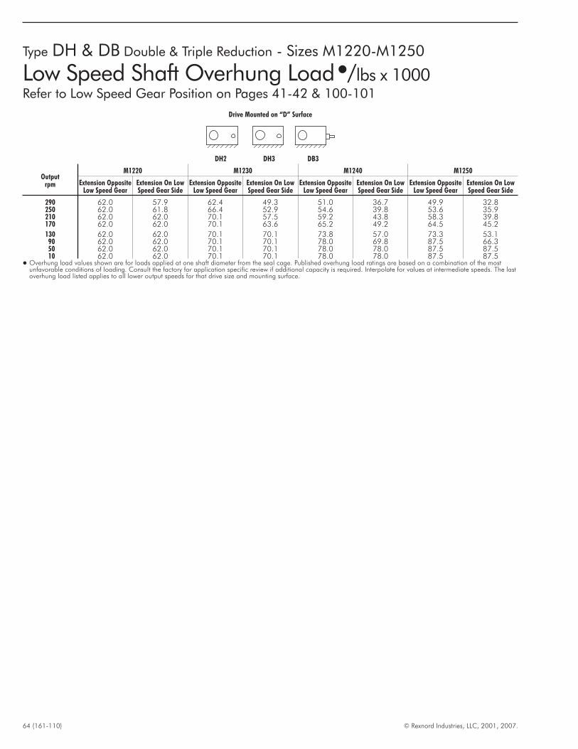
64 (161-110) © Rexnord Industries, LLC, 2001, 2007.
Type DH & DB Double & Triple Reduction - Sizes M1220-M1250
Low Speed Shaft Overhung Load�/lbs x 1000Refer to Low Speed Gear Position on Pages 41-42 & 100-101
Drive Mounted on “D” Surface
DH2 DH3 DB3
Outputrpm
M1220 M1230 M1240 M1250
Extension OppositeLow Speed Gear
Extension On LowSpeed Gear Side
Extension OppositeLow Speed Gear
Extension On LowSpeed Gear Side
Extension OppositeLow Speed Gear
Extension On LowSpeed Gear Side
Extension OppositeLow Speed Gear
Extension On LowSpeed Gear Side
290 62.0 57.9 62.4 49.3 51.0 36.7 49.9 32.8250 62.0 61.8 66.4 52.9 54.6 39.8 53.6 35.9210 62.0 62.0 70.1 57.5 59.2 43.8 58.3 39.8170 62.0 62.0 70.1 63.6 65.2 49.2 64.5 45.2
130 62.0 62.0 70.1 70.1 73.8 57.0 73.3 53.190 62.0 62.0 70.1 70.1 78.0 69.8 87.5 66.350 62.0 62.0 70.1 70.1 78.0 78.0 87.5 87.510 62.0 62.0 70.1 70.1 78.0 78.0 87.5 87.5
� Overhung load values shown are for loads applied at one shaft diameter from the seal cage. Published overhung load ratings are based on a combination of the mostunfavorable conditions of loading. Consult the factory for application specific review if additional capacity is required. Interpolate for values at intermediate speeds. The lastoverhung load listed applies to all lower output speeds for that drive size and mounting surface.
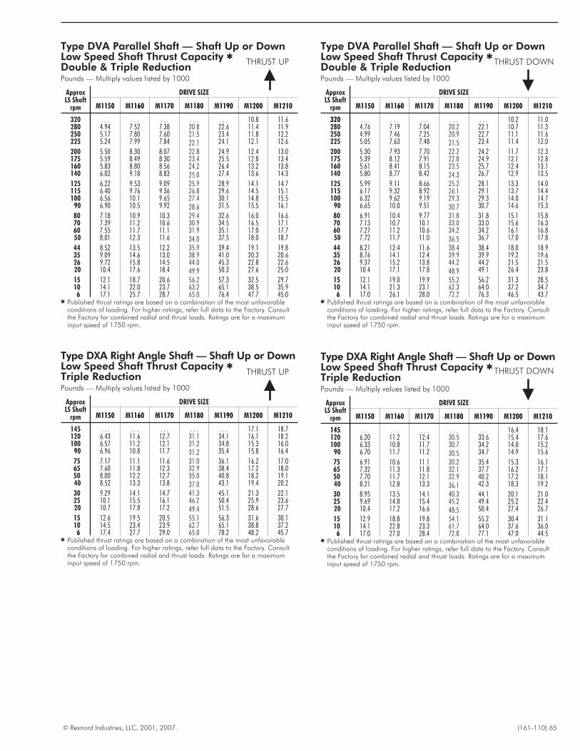
© Rexnord Industries, LLC, 2001, 2007. (161-110) 65
Type DVA Parallel Shaft — Shaft Up or DownLow Speed Shaft Thrust Capacity �
Double & Triple ReductionPounds — Multiply values listed by 1000
ApproxLS Shaft
rpm
DRIVE SIZE
M1150 M1160 M1170 M1180 M1190 M1200 M1210
320 . . . . . . . . . . . . . . . 10.8 11.6280 4.94 7.52 7.38 20.8 22.6 11.4 11.9250 5.17 7.80 7.60 21.5 23.4 11.8 12.2225 5.24 7.99 7.84 22.1 24.1 12.1 12.6
200 5.50 8.30 8.07 22.8 24.9 12.4 13.0175 5.59 8.49 8.30 23.4 25.5 12.8 13.4160 5.83 8.80 8.56 24.2 26.4 13.2 13.8140 6.02 9.18 8.83 25.0 27.4 13.6 14.3
125 6.22 9.53 9.09 25.9 28.9 14.1 14.7115 6.40 9.76 9.36 26.8 29.6 14.5 15.1100 6.56 10.1 9.65 27.4 30.1 14.8 15.5
90 6.90 10.5 9.92 28.6 31.5 15.5 16.1
80 7.18 10.9 10.3 29.4 32.6 16.0 16.670 7.39 11.2 10.6 30.9 34.5 16.5 17.160 7.55 11.7 11.1 31.9 35.1 17.0 17.750 8.01 12.3 11.6 34.0 37.5 18.0 18.7
44 8.52 13.5 12.2 35.9 39.4 19.1 19.835 9.09 14.6 13.0 38.9 41.0 20.3 20.626 9.72 15.8 14.5 44.0 45.3 22.8 22.620 10.4 17.6 18.4 49.9 50.3 27.6 25.0
15 12.1 18.7 20.6 56.2 57.3 32.5 29.710 14.1 22.0 23.7 63.2 65.1 38.5 35.96 17.1 25.7 28.7 65.0 76.4 47.7 45.0
� Published thrust ratings are based on a combination of the most unfavorableconditions of loading. For higher ratings, refer full data to the Factory. Consultthe Factory for combined radial and thrust loads. Ratings are for a maximuminput speed of 1750 rpm.
Type DXA Right Angle Shaft — Shaft Up or DownLow Speed Shaft Thrust Capacity �
Triple ReductionPounds — Multiply values listed by 1000
ApproxLS Shaft
rpm
DRIVE SIZE
M1150 M1160 M1170 M1180 M1190 M1200 M1210
145 . . . . . . . . . . . . . . . 17.1 18.7120 6.43 11.6 12.7 31.1 34.1 16.1 18.2100 6.57 11.2 12.1 31.2 34.8 15.3 16.0
90 6.96 10.8 11.7 31.2 35.4 15.8 16.4
75 7.17 11.1 11.6 31.0 36.1 16.2 17.065 7.60 11.8 12.3 32.9 38.4 17.2 18.050 8.00 12.2 12.7 35.0 40.8 18.2 19.140 8.52 13.3 13.8 37.0 43.1 19.4 20.2
30 9.29 14.1 14.7 41.3 45.1 21.3 22.125 10.1 15.5 16.1 46.2 50.4 25.9 23.620 10.7 17.8 17.2 49.4 51.5 28.6 27.7
15 12.6 19.5 20.5 55.1 56.3 31.6 30.110 14.5 23.4 23.9 62.7 65.1 38.8 37.26 17.4 27.7 29.0 65.0 78.2 48.2 45.7
� Published thrust ratings are based on a combination of the most unfavorableconditions of loading. For higher ratings, refer full data to the Factory. Consultthe Factory for combined radial and thrust loads. Ratings are for a maximuminput speed of 1750 rpm.
Type DVA Parallel Shaft — Shaft Up or DownLow Speed Shaft Thrust Capacity �
Double & Triple ReductionPounds — Multiply values listed by 1000
ApproxLS Shaft
rpm
DRIVE SIZE
M1150 M1160 M1170 M1180 M1190 M1200 M1210
320 . . . . . . . . . . . . . . . 10.2 11.0280 4.76 7.19 7.04 20.2 22.1 10.7 11.3250 4.99 7.46 7.25 20.9 22.7 11.1 11.6225 5.05 7.63 7.48 21.5 23.4 11.4 12.0
200 5.30 7.93 7.70 22.2 24.2 11.7 12.3175 5.39 8.12 7.91 22.8 24.9 12.1 12.8160 5.61 8.41 8.15 23.5 25.7 12.4 13.1140 5.80 8.77 8.42 24.3 26.7 12.9 13.5
125 5.99 9.11 8.66 25.2 28.1 13.3 14.0115 6.17 9.32 8.92 26.1 29.1 13.7 14.4100 6.32 9.62 9.19 29.3 29.3 14.0 14.7
90 6.65 10.0 9.51 30.7 30.7 14.6 15.3
80 6.91 10.4 9.77 31.8 31.8 15.1 15.870 7.13 10.7 10.1 33.0 33.0 15.6 16.360 7.27 11.2 10.6 34.2 34.2 16.1 16.850 7.72 11.7 11.0 36.5 36.7 17.0 17.8
44 8.21 12.4 11.6 38.4 38.4 18.0 18.935 8.76 14.1 12.4 39.9 39.9 19.2 19.626 9.37 15.2 13.8 44.2 44.2 21.5 21.520 10.4 17.1 17.8 48.9 49.1 26.4 23.8
15 12.1 19.0 19.9 55.2 56.2 31.3 28.510 14.1 21.3 23.1 62.3 64.0 37.2 34.76 17.0 26.1 28.0 72.2 76.3 46.5 43.7
� Published thrust ratings are based on a combination of the most unfavorableconditions of loading. For higher ratings, refer full data to the Factory. Consultthe Factory for combined radial and thrust loads. Ratings are for a maximuminput speed of 1750 rpm.
Type DXA Right Angle Shaft — Shaft Up or DownLow Speed Shaft Thrust Capacity �
Triple ReductionPounds — Multiply values listed by 1000
ApproxLS Shaft
rpm
DRIVE SIZE
M1150 M1160 M1170 M1180 M1190 M1200 M1210
145 . . . . . . . . . . . . . . . 16.4 18.1120 6.20 11.2 12.4 30.5 33.6 15.4 17.6100 6.33 10.8 11.7 30.7 34.2 14.0 15.2
90 6.70 11.7 11.2 30.5 34.7 14.9 15.6
75 6.91 10.6 11.1 30.2 35.4 15.3 16.165 7.32 11.3 11.8 32.1 37.7 16.2 17.150 7.70 11.7 12.1 32.9 40.2 17.2 18.140 8.21 12.8 13.3 36.1 42.3 18.3 19.2
30 8.95 13.5 14.1 40.3 44.1 20.1 21.025 9.69 14.8 15.4 45.2 49.4 25.2 22.420 10.4 17.2 16.6 48.5 50.4 27.4 26.7
15 12.9 18.8 19.8 54.1 55.2 30.4 31.110 14.1 22.8 23.3 61.7 64.0 37.6 36.06 17.0 27.0 28.4 72.8 77.1 47.0 44.5
� Published thrust ratings are based on a combination of the most unfavorableconditions of loading. For higher ratings, refer full data to the Factory. Consultthe Factory for combined radial and thrust loads. Ratings are for a maximuminput speed of 1750 rpm.
THRUST UP THRUST DOWN
THRUST UP THRUST DOWN
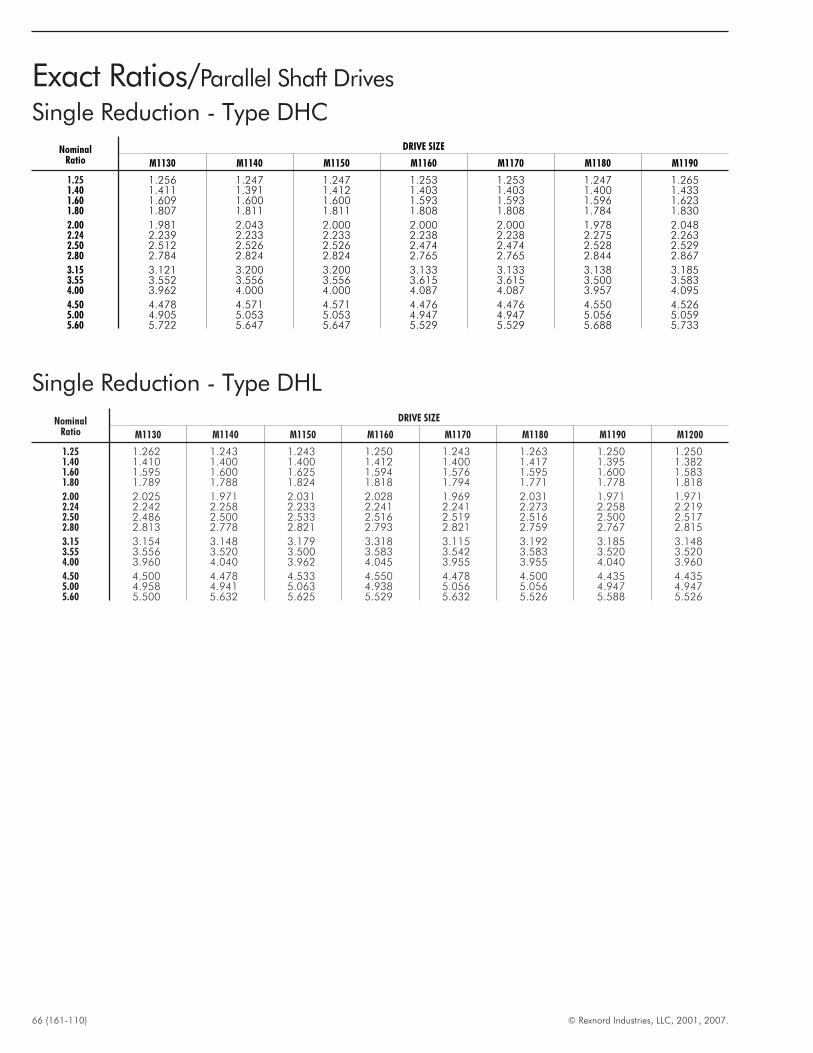
66 (161-110) © Rexnord Industries, LLC, 2001, 2007.
Exact Ratios/Parallel Shaft Drives
Single Reduction - Type DHC
NominalRatio
DRIVE SIZE
M1130 M1140 M1150 M1160 M1170 M1180 M1190
1.25 1.256 1.247 1.247 1.253 1.253 1.247 1.2651.40 1.411 1.391 1.412 1.403 1.403 1.400 1.4331.60 1.609 1.600 1.600 1.593 1.593 1.596 1.6231.80 1.807 1.811 1.811 1.808 1.808 1.784 1.830
2.00 1.981 2.043 2.000 2.000 2.000 1.978 2.0482.24 2.239 2.233 2.233 2.238 2.238 2.275 2.2632.50 2.512 2.526 2.526 2.474 2.474 2.528 2.5292.80 2.784 2.824 2.824 2.765 2.765 2.844 2.867
3.15 3.121 3.200 3.200 3.133 3.133 3.138 3.1853.55 3.552 3.556 3.556 3.615 3.615 3.500 3.5834.00 3.962 4.000 4.000 4.087 4.087 3.957 4.095
4.50 4.478 4.571 4.571 4.476 4.476 4.550 4.5265.00 4.905 5.053 5.053 4.947 4.947 5.056 5.0595.60 5.722 5.647 5.647 5.529 5.529 5.688 5.733
Single Reduction - Type DHL
NominalRatio
DRIVE SIZE
M1130 M1140 M1150 M1160 M1170 M1180 M1190 M1200
1.25 1.262 1.243 1.243 1.250 1.243 1.263 1.250 1.2501.40 1.410 1.400 1.400 1.412 1.400 1.417 1.395 1.3821.60 1.595 1.600 1.625 1.594 1.576 1.595 1.600 1.5831.80 1.789 1.788 1.824 1.818 1.794 1.771 1.778 1.818
2.00 2.025 1.971 2.031 2.028 1.969 2.031 1.971 1.9712.24 2.242 2.258 2.233 2.241 2.241 2.273 2.258 2.2192.50 2.486 2.500 2.533 2.516 2.519 2.516 2.500 2.5172.80 2.813 2.778 2.821 2.793 2.821 2.759 2.767 2.815
3.15 3.154 3.148 3.179 3.318 3.115 3.192 3.185 3.1483.55 3.556 3.520 3.500 3.583 3.542 3.583 3.520 3.5204.00 3.960 4.040 3.962 4.045 3.955 3.955 4.040 3.960
4.50 4.500 4.478 4.533 4.550 4.478 4.500 4.435 4.4355.00 4.958 4.941 5.063 4.938 5.056 5.056 4.947 4.9475.60 5.500 5.632 5.625 5.529 5.632 5.526 5.588 5.526
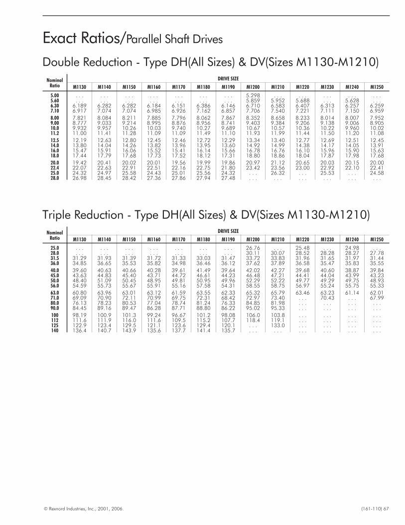
© Rexnord Industries, Inc., 2001, 2006. (161-110) 67
Exact Ratios/Parallel Shaft Drives
NominalRatio
DRIVE SIZE
M1130 M1140 M1150 M1160 M1170 M1180 M1190 M1200 M1210 M1220 M1230 M1240 M1250
5.00 . . . . . . . . . . . . . . . . . . . . . 5.298 . . . . . . . . . . . . . . .5.60 . . . . . . . . . . . . . . . . . . . . . 5.859 5.952 5.688 . . . 5.628 . . .6.30 6.189 6.282 6.282 6.184 6.151 6.386 6.146 6.710 6.583 6.407 6.313 6.257 6.2597.10 6.917 7.074 7.074 6.985 6.926 7.162 6.857 7.706 7.540 7.221 7.111 7.150 6.959
8.00 7.821 8.084 8.211 7.885 7.796 8.062 7.867 8.352 8.658 8.233 8.014 8.007 7.9529.00 8.777 9.033 9.214 8.995 8.876 8.956 8.741 9.403 9.384 9.206 9.138 9.006 8.90510.0 9.932 9.957 10.26 10.03 9.740 10.27 9.689 10.67 10.57 10.36 10.22 9.960 10.0211.2 11.00 11.41 11.28 11.09 11.09 11.49 11.10 11.93 11.99 11.44 11.50 11.20 11.08
12.5 12.19 12.63 12.80 12.45 12.46 12.72 12.29 13.34 13.40 12.77 12.69 12.51 12.4514.0 13.80 14.04 14.26 13.82 13.96 13.95 13.60 14.92 14.99 14.38 14.17 14.05 13.9116.0 15.47 15.91 16.06 15.52 15.41 16.14 15.66 16.78 16.76 16.10 15.96 15.90 15.6318.0 17.44 17.79 17.68 17.73 17.52 18.12 17.31 18.80 18.86 18.04 17.87 17.98 17.68
20.0 19.42 20.41 20.02 20.01 19.56 19.99 19.86 20.97 21.12 20.65 20.03 20.15 20.0022.4 22.07 22.63 22.91 22.51 22.16 22.75 21.80 23.42 23.56 23.00 22.92 22.10 22.4125.0 24.32 24.97 25.58 24.43 25.01 25.56 24.32 . . . 26.32 . . . 25.53 . . . 24.5828.0 26.98 28.45 28.42 27.36 27.86 27.94 27.48 . . . . . . . . . . . . . . . . . .
Double Reduction - Type DH(All Sizes) & DV(Sizes M1130-M1210)
Triple Reduction - Type DH(All Sizes) & DV(Sizes M1130-M1210)
NominalRatio
DRIVE SIZE
M1130 M1140 M1150 M1160 M1170 M1180 M1190 M1200 M1210 M1220 M1230 M1240 M1250
25.0 . . . . . . . . . . . . . . . . . . . . . 26.76 . . . 25.48 . . . 24.98 . . .28.0 . . . . . . . . . . . . . . . . . . . . . 30.11 30.07 28.52 28.28 28.27 27.7831.5 31.29 31.93 31.39 31.72 31.33 33.03 31.47 33.72 33.83 31.96 31.65 31.97 31.4436.0 34.85 36.65 35.53 35.82 34.98 36.46 36.12 37.62 37.89 36.58 35.47 35.83 35.55
40.0 39.60 40.63 40.66 40.28 39.61 41.49 39.64 42.02 42.27 39.68 40.60 38.87 39.8445.0 43.63 44.83 45.40 43.71 44.72 46.61 44.23 46.48 47.21 44.41 44.04 43.99 43.2350.0 48.40 51.09 50.45 48.95 49.81 50.95 49.96 52.29 52.22 49.77 49.29 49.75 48.9356.0 54.59 55.73 55.67 55.91 55.16 57.58 54.31 58.55 58.75 56.97 55.24 55.75 55.33
63.0 60.80 63.96 63.01 63.12 61.59 63.55 62.33 65.32 65.79 63.46 63.23 61.14 62.0171.0 69.09 70.90 72.11 70.99 69.75 72.31 68.42 72.97 73.40 . . . 70.43 . . . 67.9980.0 76.13 78.23 80.53 77.04 78.74 81.24 76.33 84.85 81.98 . . . . . . . . . . . .90.0 84.45 89.16 89.47 86.28 87.71 88.80 86.22 95.02 95.33 . . . . . . . . . . . .
100 98.19 100.9 101.3 99.24 96.67 101.2 98.08 106.0 103.8 . . . . . . . . . . . .112 111.6 111.9 116.0 111.6 109.5 115.2 107.7 118.4 119.1 . . . . . . . . . . . .125 122.9 123.4 129.5 121.1 123.6 129.4 120.1 . . . 133.0 . . . . . . . . . . . .140 136.4 140.7 143.9 135.6 137.7 141.4 135.7 . . . . . . . . . . . . . . . . . .
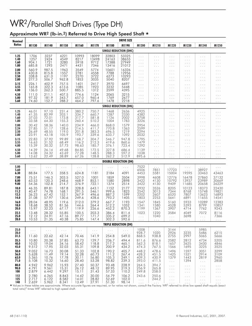
68 (161-110) © Rexnord Industries, LLC, 2001, 2007.
WR2/Parallel Shaft Drives (Type DH)Approximate WR2 (lb-in.2) Referred to Drive High Speed Shaft �
NominalRatios
DRIVE SIZE
M1130 M1140 M1150 M1160 M1170 M1180 M1190 M1200 M1210 M1220 M1230 M1240 M1250
SINGLE REDUCTION (DHC)
1.25 1706 3237 6221 10993 18099 32803 53325 . . . . . . . . . . . . . . . . . .1.40 1257 2424 4549 8217 13498 24163 38655 . . . . . . . . . . . . . . . . . .1.60 904.1 1721 3280 5918 9712 17388 27949 . . . . . . . . . . . . . . . . . .1.80 685.8 1293 2471 4431 7346 13416 21012 . . . . . . . . . . . . . . . . . .
2.00 560.9 987.5 1963 3549 5774 10601 16326 . . . . . . . . . . . . . . . . . .2.24 430.8 815.8 1557 2781 4558 7788 12956 . . . . . . . . . . . . . . . . . .2.50 338.8 631.0 1197 2270 3722 6273 10293 . . . . . . . . . . . . . . . . . .2.80 277.3 506.7 962.8 1853 3035 5040 8207 . . . . . . . . . . . . . . . . . .
3.15 226.1 402.9 757.5 1401 2417 3970 6697 . . . . . . . . . . . . . . . . . .3.55 165.8 322.3 613.6 1085 1923 3232 5448 . . . . . . . . . . . . . . . . . .4.00 136.0 262.3 500.7 885.5 1312 2599 4395 . . . . . . . . . . . . . . . . . .
4.50 111.0 211.1 407.5 774.6 1124 2065 3215 . . . . . . . . . . . . . . . . . .5.00 97.32 181.9 343.7 657.0 960.4 1769 2677 . . . . . . . . . . . . . . . . . .5.60 74.60 152.7 288.2 464.2 797.6 1478 2218 . . . . . . . . . . . . . . . . . .
SINGLE REDUCTION (DHL)
1.25 46.01 97.10 231.4 380.2 750.7 1468 2636 4925 . . . . . . . . . . . . . . .1.40 41.35 82.99 203.1 334.7 660.7 1287 2330 4382 . . . . . . . . . . . . . . .1.60 37.03 72.01 173.8 317.7 581.8 1126 2002 3758 . . . . . . . . . . . . . . .1.80 33.58 64.30 155.3 260.4 510.2 1004 1783 3226 . . . . . . . . . . . . . . .
2.00 30.42 58.36 140.0 234.9 466.0 868.0 1579 2954 . . . . . . . . . . . . . . .2.24 27.85 51.17 128.6 214.5 411.7 770.8 1363 2599 . . . . . . . . . . . . . . .2.50 26.69 48.55 119.0 201.8 383.3 696.5 1219 2294 . . . . . . . . . . . . . . .2.80 23.91 43.18 105.9 193.7 339.6 633.7 1092 2032 . . . . . . . . . . . . . . .
3.15 22.83 37.92 99.89 168.7 304.7 546.7 947.8 1795 . . . . . . . . . . . . . . .3.55 16.63 31.52 68.49 116.2 212.3 419.6 860.6 1479 . . . . . . . . . . . . . . .4.00 15.39 30.32 57.73 98.63 185.7 376.1 723.4 1292 . . . . . . . . . . . . . . .
4.50 14.39 26.14 49.68 84.85 172.5 327.8 686.4 1139 . . . . . . . . . . . . . . .5.00 14.08 24.32 43.69 77.28 148.5 288.3 597.2 1038 . . . . . . . . . . . . . . .5.60 13.62 22.49 38.89 67.26 128.8 262.2 512.9 895.6 . . . . . . . . . . . . . . .
DOUBLE REDUCTION (DH)
5.00 . . . . . . . . . . . . . . . . . . . . . 7522 . . . . . . . . . . . . . . .5.60 . . . . . . . . . . . . . . . . . . . . . 6506 7851 17723 . . . 38927 . . .6.30 88.84 177.5 358.5 624.8 1181 2184 4091 4453 5581 15004 19595 33463 43463
7.00 75.51 146.3 303.5 527.0 1001 1859 3504 3998 4608 12776 16478 27860 371328.00 63.53 120.3 248.6 468.9 853.1 1580 2898 3422 4130 10792 13937 23989 306699.00 54.36 102.8 214.7 376.9 722.1 1374 2514 3422 4130 9409 11685 20658 26229
10.0 46.35 89.81 187.8 328.8 643.1 1152 2177 2932 3526 8205 10123 18373 2243011.2 40.47 74.78 168.1 291.5 546.1 999.6 1823 2542 3013 7344 8768 15748 1982112.5 36.23 67.42 152.1 267.9 496.6 887.2 1599 2202 2607 6520 7807 13623 1689314.0 31.08 57.97 130.6 249.6 428.6 793.2 1405 1803 2253 5641 6891 11655 14541
16.0 28.04 48.95 119.6 212.0 379.2 667.7 1193 1547 1845 5160 5933 10289 1238318.0 18.68 38.52 81.56 144.6 264.4 512.2 1052 1341 1580 4528 5393 8799 1085720.0 15.97 32.23 67.17 119.9 226.6 452.2 870.3 1199 1367 3907 4714 7762 9243
22.5 13.48 28.32 55.85 100.5 203.3 386.4 811.4 1023 1220 3584 4049 7072 811625.0 12.12 24.91 47.16 89.77 171.7 335.2 699.2 . . . 1040 . . . 3698 . . . 736628.0 10.53 21.35 40.38 75.85 147.4 302.3 592.6 . . . . . . . . . . . . . . . . . .
TRIPLE REDUCTION (DH)
25.0 . . . . . . . . . . . . . . . . . . . . . 1008 . . . 3144 . . . 5985 . . .28.0 . . . . . . . . . . . . . . . . . . . . . 928.7 1020 2926 3235 5486 621531.5 11.60 22.62 42.14 70.46 141.9 254.8 549.0 868.5 938.8 2755 2997 5065 5666
35.5 10.80 20.38 37.85 63.73 129.7 236.7 494.4 811.6 876.6 2582 2812 4734 520540.0 10.02 19.04 34.16 58.42 118.8 217.2 465.1 562.3 818.1 1657 2625 3430 484645.0 9.512 17.95 32.03 55.31 109.8 200.9 434.2 474.3 767.5 1566 1695 3225 3525
50.0 9.052 16.73 30.08 51.33 102.8 190.2 405.7 448.2 478.6 1496 1597 3051 329956.0 5.628 11.49 19.14 32.28 60.73 111.2 267.4 428.2 451.5 1425 1521 2914 310963.0 5.365 10.76 17.78 30.11 56.80 105.3 249.1 409.3 430.9 1379 1443 2819 296071.0 5.108 10.32 16.60 28.40 53.28 98.82 239.3 393.0 411.5 . . . 1394 . . . 2858
80.0 4.942 9.962 15.93 27.40 50.37 93.48 228.9 264.5 394.7 . . . . . . . . . . . .90.0 4.791 9.561 15.31 26.12 48.12 89.95 219.3 256.9 265.8 . . . . . . . . . . . .100 2.879 6.442 9.297 15.11 31.43 57.33 110.2 249.8 258.0 . . . . . . . . . . . .
112 2.780 6.265 8.843 14.42 30.00 54.79 106.2 243.6 250.6 . . . . . . . . . . . .125 2.717 6.122 8.582 14.01 28.82 52.69 102.0 . . . 244.2 . . . . . . . . . . . .140 2.659 5.962 8.341 13.49 27.91 51.30 98.14 . . . . . . . . . . . . . . . . . .
� Values in these tables are approximate. Where accurate figures are required, or for ratios not shown, consult the Factory. WR2 referred to drive low speed shaft equals (exacttotal ratio)2 times WR2 referred to high speed shaft.

© Rexnord Industries, LLC, 2001, 2007. (161-110) 69
THIS PAGE INTENTIONALLY LEFT BLANK
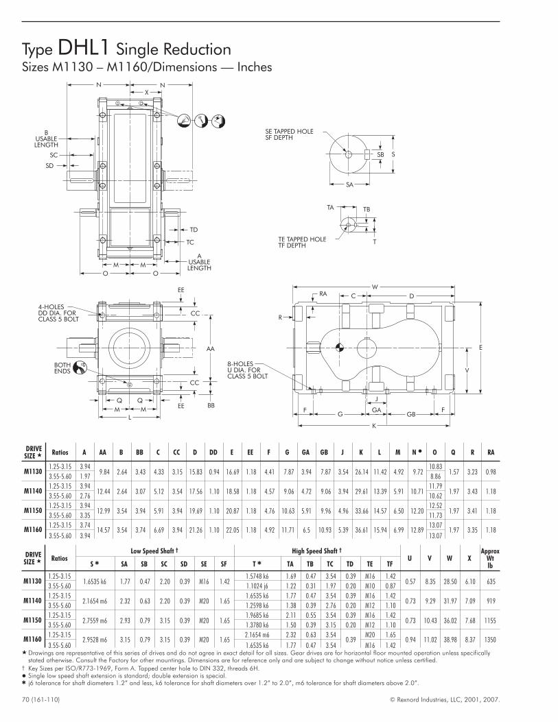
70 (161-110) © Rexnord Industries, LLC, 2001, 2007.
Type DHL1 Single ReductionSizes M1130 – M1160/Dimensions — Inches
NX
N
BUSABLELENGTH
SC
SD
TD
TC
AUSABLELENGTH
M M
O O
TE TAPPED HOLETF DEPTH
T
TBTA
SA
SB S
SE TAPPED HOLESF DEPTH
EE
CC
AA
BB
CC
EEQQ
MM
BOTHENDS
4-HOLESDD DIA. FORCLASS 5 BOLT
L
W
E
V
FF GAGBG
K
8-HOLESU DIA. FORCLASS 5 BOLT
DC
J
R
RA
DRIVESIZE � Ratios A AA B BB C CC D DD E EE F G GA GB J K L M N � O Q R RA
M11301.25-3.15 3.94
9.84 2.64 3.43 4.33 3.15 15.83 0.94 16.69 1.18 4.41 7.87 3.94 7.87 3.54 26.14 11.42 4.92 9.7210.83
1.57 3.23 0.983.55-5.60 1.97 8.86
M11401.25-3.15 3.94
12.44 2.64 3.07 5.12 3.54 17.56 1.10 18.58 1.18 4.57 9.06 4.72 9.06 3.94 29.61 13.39 5.91 10.7111.79
1.97 3.43 1.183.55-5.60 2.76 10.62
M11501.25-3.15 3.94
12.99 3.54 3.94 5.91 3.94 19.69 1.10 20.87 1.18 4.76 10.63 5.91 9.96 4.96 33.66 14.57 6.50 12.2012.52
1.97 3.41 1.183.55-5.60 3.35 11.73
M11601.25-3.15 3.74
14.57 3.54 3.74 6.69 3.94 21.26 1.10 22.05 1.18 4.92 11.71 6.5 10.93 5.39 36.61 15.94 6.99 12.8913.07
1.97 3.35 1.183.55-5.60 3.94 13.07
DRIVESIZE � Ratios
Low Speed Shaft † High Speed Shaft †
U V W XApprox
WtlbS � SA SB SC SD SE SF T � TA TB TC TD TE TF
M11301.25-3.15
1.6535 k6 1.77 0.47 2.20 0.39 M16 1.421.5748 k6 1.69 0.47 3.54 0.39 M16 1.42
0.57 8.35 28.50 6.10 6353.55-5.60 1.1024 j6 1.22 0.31 1.97 0.20 M10 0.87
M11401.25-3.15
2.1654 m6 2.32 0.63 2.20 0.39 M20 1.651.6535 k6 1.77 0.47 3.54 0.39 M16 1.42
0.73 9.29 31.97 7.09 9193.55-5.60 1.2598 k6 1.38 0.39 2.76 0.20 M12 1.10
M11501.25-3.15
2.7559 m6 2.93 0.79 3.15 0.39 M20 1.651.9685 k6 2.11 0.55 3.54 0.39 M16 1.42
0.73 10.43 36.02 7.68 11553.55-5.60 1.3780 k6 1.50 0.39 3.15 0.20 M12 1.10
M11601.25-3.15
2.9528 m6 3.15 0.79 3.15 0.39 M20 1.652.1654 m6 2.32 0.63 3.54
0.39M20 1.65
0.94 11.02 38.98 8.37 13503.55-5.60 1.6535 k6 1.77 0.47 3.54 M16 1.42
� Drawings are representative of this series of drives and do not agree in exact detail for all sizes. Gear drives are for horizontal floor mounted operation unless specificallystated otherwise. Consult the Factory for other mountings. Dimensions are for reference only and are subject to change without notice unless certified.
† Key Sizes per ISO/R773-1969, Form A. Tapped center hole to DIN 332, threads 6H.� Single low speed shaft extension is standard; double extension is special.� j6 tolerance for shaft diameters 1.2” and less, k6 tolerance for shaft diameters over 1.2” to 2.0”, m6 tolerance for shaft diameters above 2.0”.
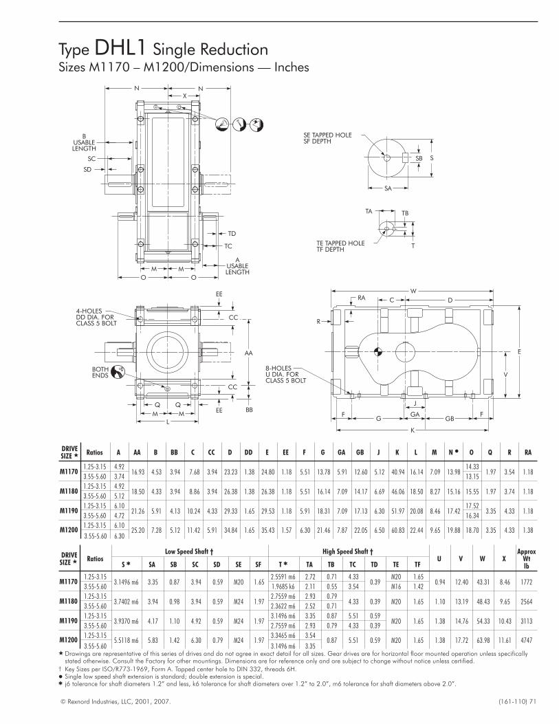
© Rexnord Industries, LLC, 2001, 2007. (161-110) 71
Type DHL1 Single ReductionSizes M1170 – M1200/Dimensions — Inches
NX
N
BUSABLELENGTH
SC
SD
TD
TC
AUSABLELENGTH
M M
O O
TE TAPPED HOLETF DEPTH
T
TBTA
SA
SB S
SE TAPPED HOLESF DEPTH
EE
CC
AA
BB
CC
EEQQ
MM
BOTHENDS
4-HOLESDD DIA. FORCLASS 5 BOLT
L
W
E
V
FF GAGBG
K
8-HOLESU DIA. FORCLASS 5 BOLT
DC
J
R
RA
DRIVESIZE � Ratios A AA B BB C CC D DD E EE F G GA GB J K L M N � O Q R RA
M11701.25-3.15 4.92
16.93 4.53 3.94 7.68 3.94 23.23 1.38 24.80 1.18 5.51 13.78 5.91 12.60 5.12 40.94 16.14 7.09 13.9814.33
1.97 3.54 1.183.55-5.60 3.74 13.15
M11801.25-3.15 4.92
18.50 4.33 3.94 8.86 3.94 26.38 1.38 26.38 1.18 5.51 16.14 7.09 14.17 6.69 46.06 18.50 8.27 15.16 15.55 1.97 3.74 1.183.55-5.60 5.12
M11901.25-3.15 6.10
21.26 5.91 4.13 10.24 4.33 29.33 1.65 29.53 1.18 5.91 18.31 7.09 17.13 6.30 51.97 20.08 8.46 17.4217.52
3.35 4.33 1.183.55-5.60 4.72 16.34
M12001.25-3.15 6.10
25.20 7.28 5.12 11.42 5.91 34.84 1.65 35.43 1.57 6.30 21.46 7.87 22.05 6.50 60.83 22.44 9.65 19.88 18.70 3.35 4.33 1.383.55-5.60 6.30
DRIVESIZE � Ratios
Low Speed Shaft † High Speed Shaft †U V W X
ApproxWtlbS � SA SB SC SD SE SF T � TA TB TC TD TE TF
M11701.25-3.15
3.1496 m6 3.35 0.87 3.94 0.59 M20 1.652.5591 m6 2.72 0.71 4.33
0.39M20 1.65
0.94 12.40 43.31 8.46 17723.55-5.60 1.9685 k6 2.11 0.55 3.54 M16 1.42
M11801.25-3.15
3.7402 m6 3.94 0.98 3.94 0.59 M24 1.972.7559 m6 2.93 0.79
4.33 0.39 M20 1.65 1.10 13.19 48.43 9.65 25643.55-5.60 2.3622 m6 2.52 0.71
M11901.25-3.15
3.9370 m6 4.17 1.10 4.92 0.59 M24 1.973.1496 m6 3.35 0.87 5.51 0.59
M20 1.65 1.38 14.76 54.33 10.43 31133.55-5.60 2.7559 m6 2.93 0.79 4.33 0.39
M12001.25-3.15
5.5118 m6 5.83 1.42 6.30 0.79 M24 1.973.3465 m6 3.54
0.87 5.51 0.59 M20 1.65 1.38 17.72 63.98 11.61 47473.55-5.60 3.1496 m6 3.35
� Drawings are representative of this series of drives and do not agree in exact detail for all sizes. Gear drives are for horizontal floor mounted operation unless specificallystated otherwise. Consult the Factory for other mountings. Dimensions are for reference only and are subject to change without notice unless certified.
† Key Sizes per ISO/R773-1969, Form A. Tapped center hole to DIN 332, threads 6H.� Single low speed shaft extension is standard; double extension is special.� j6 tolerance for shaft diameters 1.2” and less, k6 tolerance for shaft diameters over 1.2” to 2.0”, m6 tolerance for shaft diameters above 2.0”.
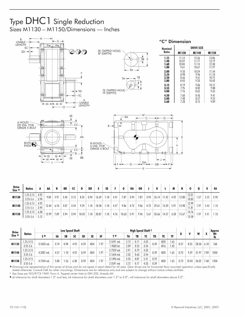
72 (161-110) © Rexnord Industries, LLC, 2001, 2007.
Type DHC1 Single ReductionSizes M1130 – M1150/Dimensions — Inches
“C” Dimension
NominalRatio
DRIVE SIZE
M1130 M1140 M1150
1.25 11.14 12.36 13.861.40 10.59 11.77 13.191.60 10.04 11.14 12.481.80 9.61 10.67 11.97
2.00 9.33 10.24 11.542.24 8.98 9.96 11.182.50 8.66 9.61 10.752.80 8.43 9.33 10.43
3.15 8.19 9.06 10.123.55 7.95 8.82 9.884.00 7.76 8.62 9.65
4.50 7.60 8.43 9.415.00 7.48 8.27 9.255.60 7.28 8.15 9.09
DriveSize � Ratios A AA B BB CC D DD E EE F G GA GB J K L M N O Q R RA
M11301.25-3.15 4.92
9.84 5.91 3.43 3.15 8.35 0.94 16.69 1.18 4.41 7.87 3.94 7.87 3.94 26.14 11.42 4.92 12.8012.01
1.57 3.23 0.983.55-5.6 3.94 10.83
M11401.25-3.15 4.92
12.44 6.10 3.07 3.54 9.29 1.10 18.58 1.18 4.57 9.06 4.72 9.06 4.72 29.61 13.39 5.91 13.9812.99
1.97 3.43 1.183.55-5.6 3.94 11.81
M11501.25-3.15 6.30
12.99 7.09 3.94 3.94 10.43 1.10 20.87 1.18 4.76 10.63 5.91 9.96 5.67 33.66 14.57 6.50 15.6714.76
1.97 3.41 1.183.55-5.6 5.12 13.58
DriveSize � Ratios
Low Speed Shaft High Speed Shaft †
U V W XApprox
WtlbS � SA SB SC SD SE SF T � TA TB TC TD TE TF
M11301.25-3.15
3.5433 m6 3.74 0.98 4.92 0.59 M24 1.972.5591 m6 2.72 0.71 4.33
0.39M20 1.65
0.57 8.35 28.50 6.10 7603.55-5.6 1.9685 k6 2.09 0.55 3.54 M16 1.42
M11401.25-3.15
4.3307 m6 4.57 1.10 4.92 0.59 M24 1.972.7559 m6 2.91 0.79 4.33
0.39 M20 1.65 0.73 9.29 31.97 7.09 10503.55-5.6 2.1654 m6 2.32 0.63 3.54
M11501.25-3.15
4.7244 m6 5.00 1.26 6.30 0.59 M24 1.973.1496 m6 3.35 0.87 5.51 0.59
M20 1.65 0.73 10.43 36.02 7.68 13503.55-5.6 2.5591 m6 2.72 0.71 4.33 0.39
� Drawings are representative of this series of drives and do not agree in exact detail for all sizes. Gear drives are for horizontal floor mounted operation unless specificallystated otherwise. Consult Falk for other mountings. Dimensions are for reference only and are subject to change without notice unless certified.
† Key Sizes per ISO/R773-1969, Form A. Tapped center hole to DIN 332, threads 6H.� j6 tolerance for shaft diameters 1.2” and less, k6 tolerance for shaft diameters over 1.2” to 2.0”, m6 tolerance for shaft diameters above 2.0”.
WC D
V
E
F
8-HOLESU DIA. FORGRADE 5 BOLT
GGA
GB F
K
J
BUSABLELENGTH
SD
SC
NX
AUSABLELENGTH
T
TD
TC
MM
AA
4-HOLESDD DIA. FORGRADE 5 BOLT
MMQ Q
L
BBEE
CC
EE
CC
BOTHENDS
SA
SB S
SE (TAPPED HOLE)SF (DEPTH)
TB
TE (TAPPED HOLE)TF (DEPTH)
O
T
TA
R
RA
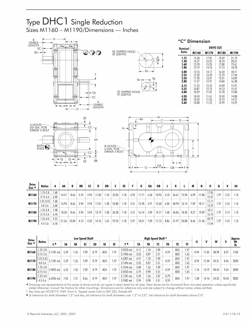
© Rexnord Industries, LLC, 2001, 2007. (161-110) 73
DriveSize � Ratios A AA B BB CC D DD E EE F G GA GB J K L M N O Q R RA
M11601.25-2.8 7.68
14.57 8.66 3.74 3.94 11.02 1.10 22.05 1.18 4.92 11.71 6.50 10.93 6.10 36.61 15.94 6.99 17.8017.05
1.97 3.35 1.183.15-5.6 6.30 15.47
M11701.25-3.55 7.68
16.93 8.66 3.94 3.94 11.81 1.38 24.80 1.18 5.51 13.78 5.91 12.60 6.30 40.94 16.14 7.09 18.1117.17
1.97 3.54 1.184.0-5.6 6.30 15.59
M11801.25-2.8 7.48
18.50 8.66 3.94 3.94 13.19 1.38 26.38 1.18 5.51 16.14 7.09 14.17 7.68 46.06 18.50 8.27 19.0918.11
1.97 3.74 1.183.15-5.6 6.10 16.73
M11901.25-4.0 9.25
21.26 10.04 4.13 4.33 14.76 1.65 29.53 1.18 5.91 18.31 7.09 17.13 8.86 51.97 20.08 8.46 21.4620.79
1.97 4.33 1.184.5-5.6 6.10 17.64
DriveSize � Ratios
Low Speed Shaft High Speed Shaft †
U V W XApprox
WtlbS � SA SB SC SD SE SF T � TA TB TC TD TE TF
M11601.25-2.8
5.1181 m6 5.39 1.26 7.09 0.79 M24 1.973.9370 m6 4.17 1.10 7.09
0.59M24 1.97
0.94 11.02 38.98 8.37 17603.15-5.6 3.1496 m6 3.35 0.87 5.51 M20 1.65
M11701.25-3.55
5.1181 m6 5.39 1.26 7.09 0.79 M24 1.974.3307 m6 4.57 1.10 7.09
0.59M24 1.97
0.94 12.40 43.31 8.46 20304.0-5.6 3.1496 m6 3.35 0.87 5.51 M20 1.65
M11801.25-2.8
5.9055 m6 6.22 1.42 7.09 0.79 M24 1.974.7244 m6 5.00 1.26 7.09
0.59M24 1.97
1.10 13.19 48.43 9.65 28903.15-5.6 3.5433 m6 3.74 0.98 5.51 M20 1.65
M11901.25-4.0
6.6926 m6 7.05 1.57 8.66 0.79 M24 1.975.1181 m6 5.39 1.26 7.87 0.79
M24 1.97 1.38 14.76 54.33 10.43 38204.5-5.6 3.7402 m6 3.94 0.98 5.51 0.59
� Drawings are representative of this series of drives and do not agree in exact detail for all sizes. Gear drives are for horizontal floor mounted operation unless specificallystated otherwise. Consult the Factory for other mountings. Dimensions are for reference only and are subject to change without notice unless certified.
† Key Sizes per ISO/R773-1969, Form A. Tapped center hole to DIN 332, threads 6H.� j6 tolerance for shaft diameters 1.2” and less, k6 tolerance for shaft diameters over 1.2” to 2.0”, m6 tolerance for shaft diameters above 2.0”.
“C” Dimension
NominalRatio
DRIVE SIZE
M1160 M1170 M1180 M1190
1.25 15.28 17.01 19.69 21.731.40 14.57 16.22 18.74 20.671.60 13.78 15.35 17.80 19.611.80 13.19 14.76 17.13 18.78
2.00 12.76 14.17 16.54 18.112.24 12.28 13.70 15.79 17.442.50 11.93 13.31 15.31 16.892.80 11.57 12.91 14.84 16.38
3.15 11.22 12.52 14.49 15.913.55 10.87 12.13 14.13 15.474.00 10.59 11.81 13.78 15.08
4.50 10.43 11.61 13.43 14.805.00 10.24 11.42 13.19 14.575.60 10.08 11.22 12.99 14.29
Type DHC1 Single ReductionSizes M1160 – M1190/Dimensions — Inches
WC D
V
E
F
8-HOLESU DIA. FORGRADE 5 BOLT
GGA
GB F
K
J
BUSABLELENGTH
SD
SC
NX
AUSABLELENGTH
T
TD
TC
MM
AA
4-HOLESDD DIA. FORGRADE 5 BOLT
MMQ Q
L
BBEE
CC
EE
CC
BOTHENDS
SA
SB S
SE (TAPPED HOLE)SF (DEPTH)
TB
TE (TAPPED HOLE)TF (DEPTH)
O
T
TA
R
RA
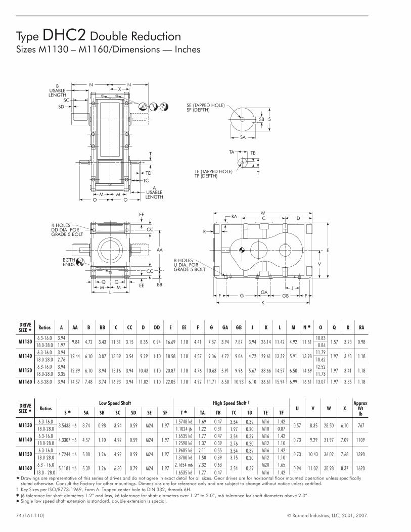
74 (161-110) © Rexnord Industries, LLC, 2001, 2007.
Type DHC2 Double ReductionSizes M1130 – M1160/Dimensions — Inches
K
WC D
V
E
F
8-HOLESU DIA. FORGRADE 5 BOLT
GGA
GB F
J
BUSABLELENGTH
SD
SC
N NX
AUSABLELENGTH
T
TD
TC
OOMM
AA
4-HOLESDD DIA. FORGRADE 5 BOLT
MMQ Q
L
BBEE
CC
EE
CC
BOTHENDS
SA
SB S
SE (TAPPED HOLE)SF (DEPTH)
TA TB
TTE (TAPPED HOLE)TF (DEPTH)
R
RA
DRIVESIZE � Ratios A AA B BB C CC D DD E EE F G GA GB J K L M N � O Q R RA
M11306.3-16.0 3.94
9.84 4.72 3.43 11.81 3.15 8.35 0.94 16.69 1.18 4.41 7.87 3.94 7.87 3.94 26.14 11.42 4.92 11.6110.83
1.57 3.23 0.9818.0-28.0 1.97 8.86
M11406.3-16.0 3.94
12.44 6.10 3.07 13.39 3.54 9.29 1.10 18.58 1.18 4.57 9.06 4.72 9.06 4.72 29.61 13.39 5.91 13.9811.79
1.97 3.43 1.1818.0-28.0 2.76 10.62
M11506.3-16.0 3.94
12.99 6.10 3.94 15.16 3.94 10.43 1.10 20.87 1.18 4.76 10.63 5.91 9.96 5.67 33.66 14.57 6.50 14.6912.52
1.97 3.41 1.1818.0-28.0 3.35 11.73
M1160 6.3-28.0 3.94 14.57 7.48 3.74 16.93 3.94 11.02 1.10 22.05 1.18 4.92 11.71 6.50 10.93 6.10 36.61 15.94 6.99 16.61 13.07 1.97 3.35 1.18
DRIVESIZE � Ratios
Low Speed Shaft High Speed Shaft †
U V W XApprox
WtlbS � SA SB SC SD SE SF T � TA TB TC TD TE TF
M11306.3-16.0
3.5433 m6 3.74 0.98 3.94 0.59 M24 1.971.5748 k6 1.69 0.47 3.54 0.39 M16 1.42
0.57 8.35 28.50 6.10 76718.0-28.0 1.1024 j6 1.22 0.31 1.97 0.20 M10 0.87
M11406.3-16.0
4.3307 m6 4.57 1.10 4.92 0.59 M24 1.971.6535 k6 1.77 0.47 3.54 0.39 M16 1.42
0.73 9.29 31.97 7.09 110918.0-28.0 1.2598 k6 1.37 0.39 2.76 0.20 M12 1.10
M11506.3-16.0
4.7244 m6 5.00 1.26 4.92 0.59 M24 1.971.9685 k6 2.11 0.55 3.54 0.39 M16 1.42
0.73 10.43 36.02 7.68 139018.0-28.0 1.3780 k6 1.50 0.39 3.15 0.20 M12 1.10
M11606.3 - 16.0
5.1181 m6 5.39 1.26 6.30 0.79 M24 1.972.1654 m6 2.32 0.63
3.54 0.39M20 1.65
0.94 11.02 38.98 8.37 162018.0 - 28.0 1.6535 k6 1.77 0.47 M16 1.42
� Drawings are representative of this series of drives and do not agree in exact detail for all sizes. Gear drives are for horizontal floor mounted operation unless specificallystated otherwise. Consult the Factory for other mountings. Dimensions are for reference only and are subject to change without notice unless certified.
† Key Sizes per ISO/R773-1969, Form A. Tapped center hole to DIN 332, threads 6H.� j6 tolerance for shaft diameters 1.2” and less, k6 tolerance for shaft diameters over 1.2” to 2.0”, m6 tolerance for shaft diameters above 2.0”.� Single low speed shaft extension is standard; double extension is special.
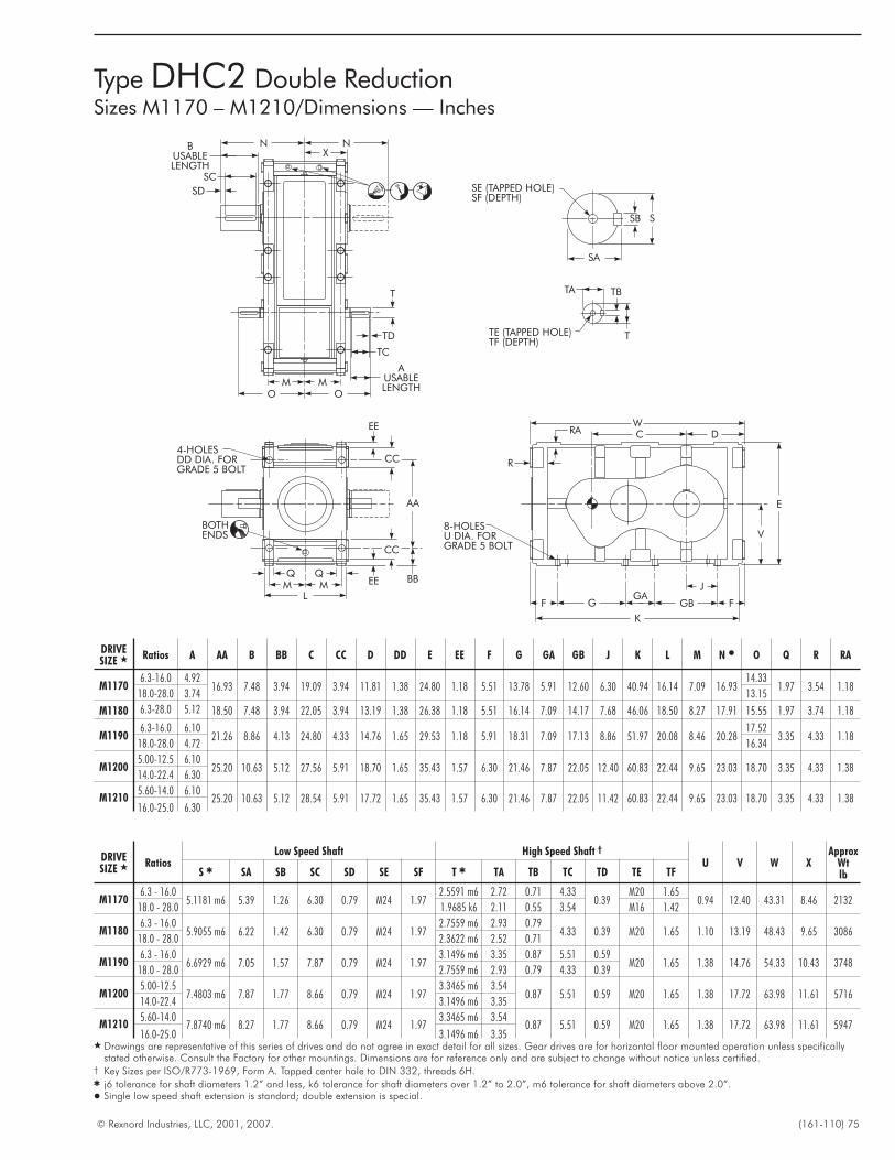
© Rexnord Industries, LLC, 2001, 2007. (161-110) 75
Type DHC2 Double ReductionSizes M1170 – M1210/Dimensions — Inches
K
WC D
V
E
F
8-HOLESU DIA. FORGRADE 5 BOLT
GGA
GB F
J
BUSABLELENGTH
SD
SC
N NX
AUSABLELENGTH
T
TD
TC
OOMM
AA
4-HOLESDD DIA. FORGRADE 5 BOLT
MMQ Q
L
BBEE
CC
EE
CC
BOTHENDS
SA
SB S
SE (TAPPED HOLE)SF (DEPTH)
TA TB
TTE (TAPPED HOLE)TF (DEPTH)
R
RA
DRIVESIZE � Ratios A AA B BB C CC D DD E EE F G GA GB J K L M N � O Q R RA
M11706.3-16.0 4.92
16.93 7.48 3.94 19.09 3.94 11.81 1.38 24.80 1.18 5.51 13.78 5.91 12.60 6.30 40.94 16.14 7.09 16.9314.33
1.97 3.54 1.1818.0-28.0 3.74 13.15
M1180 6.3-28.0 5.12 18.50 7.48 3.94 22.05 3.94 13.19 1.38 26.38 1.18 5.51 16.14 7.09 14.17 7.68 46.06 18.50 8.27 17.91 15.55 1.97 3.74 1.18
M11906.3-16.0 6.10
21.26 8.86 4.13 24.80 4.33 14.76 1.65 29.53 1.18 5.91 18.31 7.09 17.13 8.86 51.97 20.08 8.46 20.2817.52
3.35 4.33 1.1818.0-28.0 4.72 16.34
M12005.00-12.5 6.10
25.20 10.63 5.12 27.56 5.91 18.70 1.65 35.43 1.57 6.30 21.46 7.87 22.05 12.40 60.83 22.44 9.65 23.03 18.70 3.35 4.33 1.3814.0-22.4 6.30
M12105.60-14.0 6.10
25.20 10.63 5.12 28.54 5.91 17.72 1.65 35.43 1.57 6.30 21.46 7.87 22.05 11.42 60.83 22.44 9.65 23.03 18.70 3.35 4.33 1.3816.0-25.0 6.30
DRIVESIZE � Ratios
Low Speed Shaft High Speed Shaft †
U V W XApprox
WtlbS � SA SB SC SD SE SF T � TA TB TC TD TE TF
M11706.3 - 16.0
5.1181 m6 5.39 1.26 6.30 0.79 M24 1.972.5591 m6 2.72 0.71 4.33
0.39M20 1.65
0.94 12.40 43.31 8.46 213218.0 - 28.0 1.9685 k6 2.11 0.55 3.54 M16 1.42
M11806.3 - 16.0
5.9055 m6 6.22 1.42 6.30 0.79 M24 1.972.7559 m6 2.93 0.79
4.33 0.39 M20 1.65 1.10 13.19 48.43 9.65 308618.0 - 28.0 2.3622 m6 2.52 0.71
M11906.3 - 16.0
6.6929 m6 7.05 1.57 7.87 0.79 M24 1.973.1496 m6 3.35 0.87 5.51 0.59
M20 1.65 1.38 14.76 54.33 10.43 374818.0 - 28.0 2.7559 m6 2.93 0.79 4.33 0.39
M12005.00-12.5
7.4803 m6 7.87 1.77 8.66 0.79 M24 1.973.3465 m6 3.54
0.87 5.51 0.59 M20 1.65 1.38 17.72 63.98 11.61 571614.0-22.4 3.1496 m6 3.35
M12105.60-14.0
7.8740 m6 8.27 1.77 8.66 0.79 M24 1.973.3465 m6 3.54
0.87 5.51 0.59 M20 1.65 1.38 17.72 63.98 11.61 594716.0-25.0 3.1496 m6 3.35
� Drawings are representative of this series of drives and do not agree in exact detail for all sizes. Gear drives are for horizontal floor mounted operation unless specificallystated otherwise. Consult the Factory for other mountings. Dimensions are for reference only and are subject to change without notice unless certified.
† Key Sizes per ISO/R773-1969, Form A. Tapped center hole to DIN 332, threads 6H.� j6 tolerance for shaft diameters 1.2” and less, k6 tolerance for shaft diameters over 1.2” to 2.0”, m6 tolerance for shaft diameters above 2.0”.� Single low speed shaft extension is standard; double extension is special.
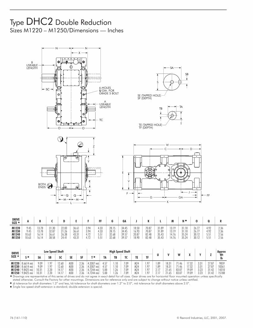
76 (161-110) © Rexnord Industries, LLC, 2001, 2007.
Type DHC2 Double ReductionSizes M1220 – M1250/Dimensions — Inches
FFF
J
GA
K
G
V
E
DC
W
R
Y
Z
BOTHENDS
MML
TC
N
X
N
BUSEABLELENGTH
SC6-HOLES
DIA. FORGRADE 5 BOLTU
AUSEABLELENGTH
OO
TATB
TTE (TAPPED HOLE)TF (DEPTH)
SB
SA
S
SE (TAPPED HOLE)SF (DEPTH)
DRIVESIZE � A B C D E F FF G GA J K L M N � O Q R
M1220 9.45 13.78 31.30 22.83 36.61 3.94 4.33 28.15 34.45 18.50 70.87 31.89 13.19 31.10 26.77 4.92 2.36M1230 9.45 13.78 32.87 21.26 36.61 3.94 4.33 28.15 34.45 16.93 70.87 31.89 13.19 31.10 26.77 4.92 2.36M1240 10.63 16.14 36.61 26.38 43.31 4.72 5.51 32.68 39.57 20.87 82.48 35.43 14.76 35.24 30.12 5.51 2.56M1250 10.63 16.14 38.58 24.41 43.31 4.72 5.51 32.68 39.57 18.90 82.48 35.43 14.76 35.24 30.12 5.51 2.56
DRIVESIZE �
Low Speed Shaft High Speed ShaftU V W X Y Z
ApproxWtlbS � SA SB SC SE SF T � TA TB TC TE TF
M1220 8.6614 m6 9.09 1.97 12.60 M30 2.36 4.3307 m6 4.57 1.10 7.09 M24 1.97 1.89 18.31 71.46 17.32 3.31 27.87 9859M1230 8.6614 m6 9.09 1.97 12.60 M30 2.36 4.3307 m6 4.57 1.10 7.09 M24 1.97 1.89 18.31 71.46 17.32 3.31 27.87 10361M1240 9.8425 m6 10.31 2.20 14.17 M30 2.36 4.7244 m6 5.00 1.26 7.09 M24 1.97 2.17 21.65 83.07 19.09 3.23 31.42 14310M1250 9.8425 m6 10.31 2.20 14.17 M30 2.36 4.7244 m6 5.00 1.26 7.09 M24 1.97 2.17 21.65 83.07 19.09 3.23 31.42 15188
� Drawings are representative of this series of drives and do not agree in exact detail for all sizes. Gear drives are for horizontal floor mounted operation unless specificallystated otherwise. Consult the Factory for other mountings. Dimensions are for reference only and are subject to change without notice unless certified.
� j6 tolerance for shaft diameters 1.2” and less, k6 tolerance for shaft diameters over 1.2” to 2.0”, m6 tolerance for shaft diameters above 2.0”.� Single low speed shaft extension is standard; double extension is special.
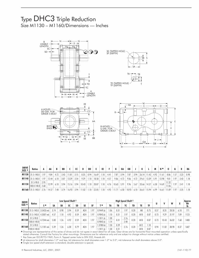
© Rexnord Industries, LLC, 2001, 2007. (161-110) 77
WC D
V
E
F
8-HOLESU DIA. FORGRADE 5 BOLT
GGA
GB F
K
J
BUSABLELENGTH
SD
SC
N NX
AUSABLELENGTH
T
TD
TC
OOMM
AA
4-HOLESDD DIA. FORGRADE 5 BOLT
MMQ Q
L
BBEE
CC
EE
CC
BOTHENDS
SA
SB S
SE (TAPPED HOLE)SF (DEPTH)
TA TB
TTE (TAPPED HOLE)TF (DEPTH)
R
RA
Type DHC3 Triple ReductionSize M1130 – M1160/Dimensions — Inches
DRIVESIZE � Ratios A AA B BB C CC D DD E EE F G GA GB J K L M N � O Q R RA
M1130 31.5-140.0 1.97 9.84 4.72 3.43 11.81 3.15 8.35 0.94 16.69 1.18 4.41 7.87 3.94 7.87 3.94 26.14 11.42 4.92 11.61 8.86 1.57 3.23 0.98
M1140 31.5-140.0 1.97 12.44 6.10 3.07 13.39 3.54 9.29 1.10 18.58 1.18 4.57 9.06 4.72 9.06 4.72 29.61 13.39 5.91 13.98 9.81 1.97 3.43 1.18
M115031.5-90.0 2.95
12.99 6.10 3.94 15.16 3.94 10.43 1.10 20.87 1.18 4.76 10.63 5.91 9.96 5.67 33.66 14.57 6.50 14.6911.32
1.97 3.41 1.18100.0-140.0 2.68 11.06
M1160 31.5-140.0 2.76 14.57 7.48 3.74 16.93 3.94 11.02 1.10 22.05 1.18 4.92 11.71 6.50 10.93 6.10 36.61 15.94 6.99 16.61 11.89 1.97 3.35 1.18
DRIVESIZE � Ratios
Low Speed Shaft † High Speed Shaft †
U V W XApprox
WtlbS � SA SB SC SD SE SF T � TA TB TC TD TE TF
M1130 31.5-140.0 3.5433 m6 3.74 0.98 3.94 0.59 M24 1.97 0.9449 j6 1.06 0.31 1.97 0.20 M8 0.75 0.57 8.35 28.50 6.10 771
M1140 31.5-140.0 4.3307 m6 4.57 1.10 4.92 0.59 M24 1.97 0.9843 j6 1.10 0.31 1.97 0.20 M10 0.87 0.73 9.29 31.97 7.09 1123
M115031.5-90.0
4.7244 m6 5.00 1.26 4.92 0.59 M24 1.971.1811 j6 1.30
0.312.76
0.20 M10 0.87 0.73 10.43 36.02 7.68 1400100.0-140.0 0.9843 j6 1.14 2.48
M116031.5-90.0
5.1181 m6 5.39 1.26 6.30 0.79 M24 1.971.3780 k6 1.50 0.39
2.76 0.20M12 1.10
0.94 11.02 38.98 8.37 1687100.0-140.0 1.1811 j6 1.30 0.31 M10 0.87
� Drawings are representative of this series of drives and do not agree in exact detail for all sizes. Gear drives are for horizontal floor mounted operation unless specificallystated otherwise. Consult the Factory for other mountings. Dimensions are for reference only and are subject to change without notice unless certified.
† Key Sizes per ISO/R773-1969, Form A. Tapped center hole to DIN 332, threads 6H.� j6 tolerance for shaft diameters 1.2” and less, k6 tolerance for shaft diameters over 1.2” to 2.0”, m6 tolerance for shaft diameters above 2.0”.� Single low speed shaft extension is standard; double extension is special.
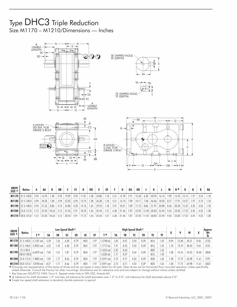
78 (161-110) © Rexnord Industries, LLC, 2001, 2007.
Type DHC3 Triple ReductionSize M1170 – M1210/Dimensions — Inches
WC D
V
E
F
8-HOLESU DIA. FORGRADE 5 BOLT
GGA
GB F
K
J
BUSABLELENGTH
SD
SC
N NX
AUSABLELENGTH
T
TD
TC
OOMM
AA
4-HOLESDD DIA. FORGRADE 5 BOLT
MMQ Q
L
BBEE
CC
EE
CC
BOTHENDS
SA
SB S
SE (TAPPED HOLE)SF (DEPTH)
TA TB
TTE (TAPPED HOLE)TF (DEPTH)
R
RA
DRIVESIZE � Ratios A AA B BB C CC D DD E EE F G GA GB J K L M N � O Q R RA
M1170 31.5-140.0 3.94 16.93 7.48 3.94 19.09 3.94 11.81 1.38 24.80 1.18 5.51 13.78 5.91 12.60 6.30 40.94 16.14 7.09 16.93 13.15 1.97 3.54 1.18
M1180 31.5-140.0 3.94 18.50 7.48 3.94 22.05 3.94 13.19 1.38 26.38 1.18 5.51 16.14 7.09 14.17 7.68 46.06 18.50 8.27 17.91 14.37 1.97 3.74 1.18
M1190 31.5-140.0 3.94 21.26 8.86 4.13 24.80 4.33 14.76 1.65 29.53 1.18 5.91 18.31 7.09 17.13 8.86 51.97 20.08 8.46 20.28 15.22 3.35 4.33 1.18
M1200 25.0-112.0 5.12 25.20 10.63 5.12 27.56 5.91 18.70 1.65 35.43 1.57 6.30 21.46 7.87 22.05 12.40 60.83 22.44 9.65 23.03 17.52 3.35 4.33 1.38
M1210 28.0-125.0 5.12 25.20 10.63 5.12 28.54 5.91 17.72 1.65 35.43 1.57 6.30 21.46 7.87 22.05 11.42 60.83 22.44 9.65 23.03 17.52 3.35 4.33 1.38
DRIVESIZE � Ratios
Low Speed Shaft † High Speed Shaft †
U V W XApprox
WtlbS � SA SB SC SD SE SF T � TA TB TC TD TE TF
M1170 31.5-140.0 5.1181 m6 5.39 1.26 6.30 0.79 M24 1.97 1.5748 k6 1.69 0.47 3.54 0.39 M16 1.42 0.94 12.40 43.31 8.46 2132
M1180 31.5-140.0 5.9055 m6 6.22 1.42 6.30 0.79 M24 1.97 1.7717 k6 1.91 0.55 3.54 0.39 M16 1.42 1.10 13.19 48.43 9.65 3131
M119031.5-90.0
6.6929 m6 7.05 1.57 7.87 0.79 M24 1.972.1654 m6 2.32 0.63
3.54 0.39M20 1.65
1.38 14.76 54.33 10.43 3858100.0-140.0 1.6535 k6 1.77 0.47 M16 1.42
M1200 25.0-112.0 7.4803 m6 7.87 1.77 8.66 0.79 M24 1.97 2.5591 m6 2.72 0.71 4.33 0.39 M20 1.65 1.38 17.72 63.98 11.61 5791
M1210 28.0-125.0 7.8740 m6 8.27 1.77 8.66 0.79 M24 1.97 2.5591 m6 2.72 0.71 4.33 0.39 M20 1.65 1.38 17.72 63.98 11.61 6023� Drawings are representative of this series of drives and do not agree in exact detail for all sizes. Gear drives are for horizontal floor mounted operation unless specifically
stated otherwise. Consult the Factory for other mountings. Dimensions are for reference only and are subject to change without notice unless certified.† Key Sizes per ISO/R773-1969, Form A. Tapped center hole to DIN 332, threads 6H.� j6 tolerance for shaft diameters 1.2” and less, k6 tolerance for shaft diameters over 1.2” to 2.0”, m6 tolerance for shaft diameters above 2.0”.� Single low speed shaft extension is standard; double extension is special.
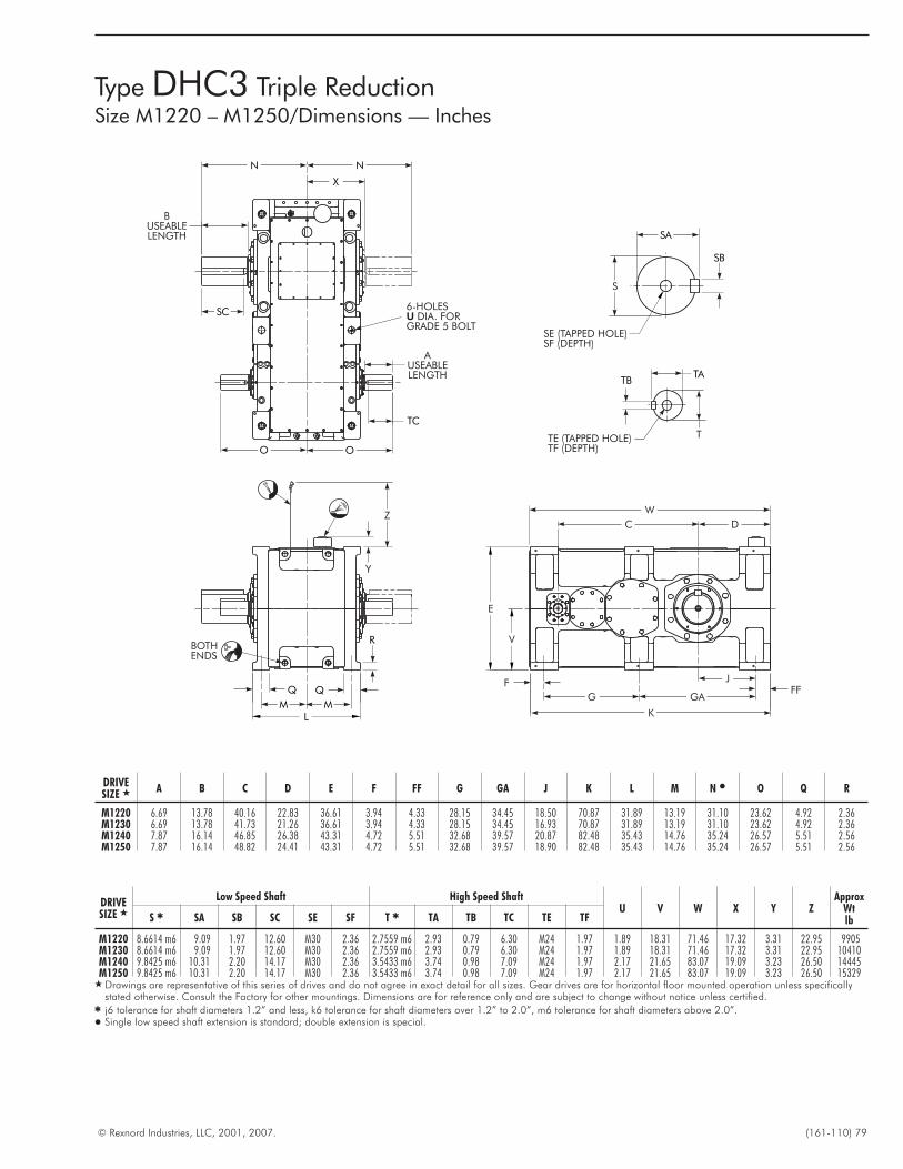
© Rexnord Industries, LLC, 2001, 2007. (161-110) 79
Type DHC3 Triple ReductionSize M1220 – M1250/Dimensions — Inches
FFF
J
GA
K
G
V
E
DC
W
R
Y
Z
BOTHENDS
MML
TC
N
X
N
BUSEABLELENGTH
SC6-HOLES
DIA. FORGRADE 5 BOLTU
AUSEABLELENGTH
OO
TATB
TTE (TAPPED HOLE)TF (DEPTH)
SB
SA
S
SE (TAPPED HOLE)SF (DEPTH)
DRIVESIZE � A B C D E F FF G GA J K L M N � O Q R
M1220 6.69 13.78 40.16 22.83 36.61 3.94 4.33 28.15 34.45 18.50 70.87 31.89 13.19 31.10 23.62 4.92 2.36M1230 6.69 13.78 41.73 21.26 36.61 3.94 4.33 28.15 34.45 16.93 70.87 31.89 13.19 31.10 23.62 4.92 2.36M1240 7.87 16.14 46.85 26.38 43.31 4.72 5.51 32.68 39.57 20.87 82.48 35.43 14.76 35.24 26.57 5.51 2.56M1250 7.87 16.14 48.82 24.41 43.31 4.72 5.51 32.68 39.57 18.90 82.48 35.43 14.76 35.24 26.57 5.51 2.56
DRIVESIZE �
Low Speed Shaft High Speed ShaftU V W X Y Z
ApproxWtlbS � SA SB SC SE SF T � TA TB TC TE TF
M1220 8.6614 m6 9.09 1.97 12.60 M30 2.36 2.7559 m6 2.93 0.79 6.30 M24 1.97 1.89 18.31 71.46 17.32 3.31 22.95 9905M1230 8.6614 m6 9.09 1.97 12.60 M30 2.36 2.7559 m6 2.93 0.79 6.30 M24 1.97 1.89 18.31 71.46 17.32 3.31 22.95 10410M1240 9.8425 m6 10.31 2.20 14.17 M30 2.36 3.5433 m6 3.74 0.98 7.09 M24 1.97 2.17 21.65 83.07 19.09 3.23 26.50 14445M1250 9.8425 m6 10.31 2.20 14.17 M30 2.36 3.5433 m6 3.74 0.98 7.09 M24 1.97 2.17 21.65 83.07 19.09 3.23 26.50 15329
� Drawings are representative of this series of drives and do not agree in exact detail for all sizes. Gear drives are for horizontal floor mounted operation unless specificallystated otherwise. Consult the Factory for other mountings. Dimensions are for reference only and are subject to change without notice unless certified.
� j6 tolerance for shaft diameters 1.2” and less, k6 tolerance for shaft diameters over 1.2” to 2.0”, m6 tolerance for shaft diameters above 2.0”.� Single low speed shaft extension is standard; double extension is special.
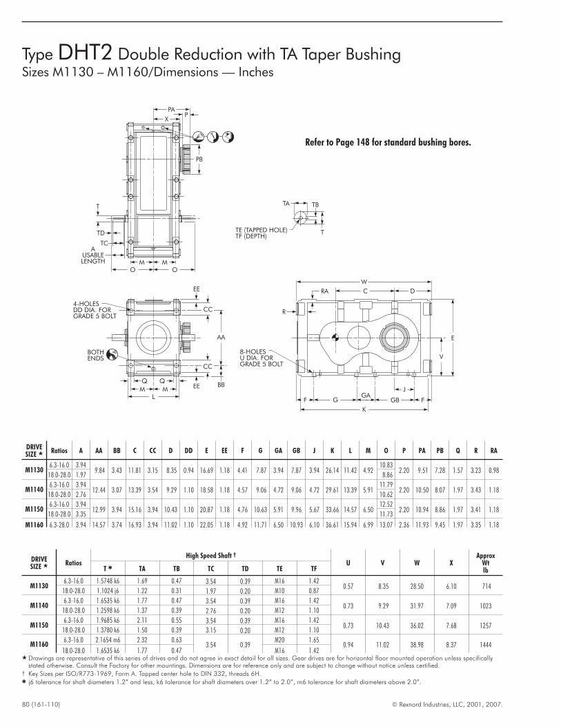
80 (161-110) © Rexnord Industries, LLC, 2001, 2007.
TA TB
TTE (TAPPED HOLE)TF (DEPTH)
T
TD
TC
X
OO
AUSABLELENGTH
PPA
PB
MM
AA
4-HOLESDD DIA. FORGRADE 5 BOLT
BBEE
CC
EE
CC
LMM
Q Q
BOTHENDS
W
C D
V
E
F
8-HOLESU DIA. FORGRADE 5 BOLT
GGA
GB F
K
J
R
RA
Type DHT2 Double Reduction with TA Taper BushingSizes M1130 – M1160/Dimensions — Inches
Refer to Page 148 for standard bushing bores.
DRIVESIZE � Ratios
High Speed Shaft †
U V W XApprox
WtlbT � TA TB TC TD TE TF
M11306.3-16.0 1.5748 k6 1.69 0.47 3.54 0.39 M16 1.42
0.57 8.35 28.50 6.10 71418.0-28.0 1.1024 j6 1.22 0.31 1.97 0.20 M10 0.87
M11406.3-16.0 1.6535 k6 1.77 0.47 3.54 0.39 M16 1.42
0.73 9.29 31.97 7.09 102318.0-28.0 1.2598 k6 1.37 0.39 2.76 0.20 M12 1.10
M11506.3-16.0 1.9685 k6 2.11 0.55 3.54 0.39 M16 1.42
0.73 10.43 36.02 7.68 125718.0-28.0 1.3780 k6 1.50 0.39 3.15 0.20 M12 1.10
M11606.3-16.0 2.1654 m6 2.32 0.63
3.54 0.39M20 1.65
0.94 11.02 38.98 8.37 144418.0-28.0 1.6535 k6 1.77 0.47 M16 1.42
� Drawings are representative of this series of drives and do not agree in exact detail for all sizes. Gear drives are for horizontal floor mounted operation unless specificallystated otherwise. Consult the Factory for other mountings. Dimensions are for reference only and are subject to change without notice unless certified.
† Key Sizes per ISO/R773-1969, Form A. Tapped center hole to DIN 332, threads 6H.� j6 tolerance for shaft diameters 1.2” and less, k6 tolerance for shaft diameters over 1.2” to 2.0”, m6 tolerance for shaft diameters above 2.0”.
DRIVESIZE � Ratios A AA BB C CC D DD E EE F G GA GB J K L M O P PA PB Q R RA
M11306.3-16.0 3.94
9.84 3.43 11.81 3.15 8.35 0.94 16.69 1.18 4.41 7.87 3.94 7.87 3.94 26.14 11.42 4.9210.83
2.20 9.51 7.28 1.57 3.23 0.9818.0-28.0 1.97 8.86
M11406.3-16.0 3.94
12.44 3.07 13.39 3.54 9.29 1.10 18.58 1.18 4.57 9.06 4.72 9.06 4.72 29.61 13.39 5.9111.79
2.20 10.50 8.07 1.97 3.43 1.1818.0-28.0 2.76 10.62
M11506.3-16.0 3.94
12.99 3.94 15.16 3.94 10.43 1.10 20.87 1.18 4.76 10.63 5.91 9.96 5.67 33.66 14.57 6.5012.52
2.20 10.94 8.86 1.97 3.41 1.1818.0-28.0 3.35 11.73
M1160 6.3-28.0 3.94 14.57 3.74 16.93 3.94 11.02 1.10 22.05 1.18 4.92 11.71 6.50 10.93 6.10 36.61 15.94 6.99 13.07 2.36 11.93 9.45 1.97 3.35 1.18
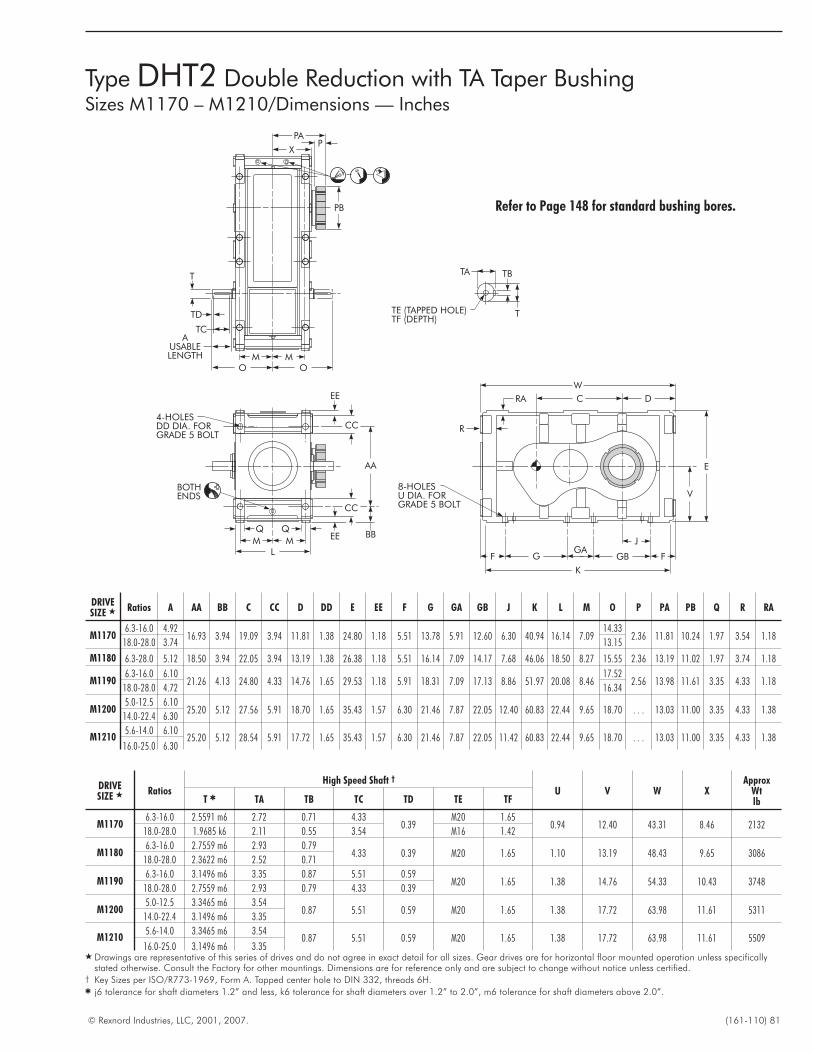
© Rexnord Industries, LLC, 2001, 2007. (161-110) 81
TA TB
TTE (TAPPED HOLE)TF (DEPTH)
T
TD
TC
X
OO
AUSABLELENGTH
PPA
PB
MM
AA
4-HOLESDD DIA. FORGRADE 5 BOLT
BBEE
CC
EE
CC
LMM
Q Q
BOTHENDS
W
C D
V
E
F
8-HOLESU DIA. FORGRADE 5 BOLT
GGA
GB F
K
J
R
RA
Type DHT2 Double Reduction with TA Taper BushingSizes M1170 – M1210/Dimensions — Inches
Refer to Page 148 for standard bushing bores.
DRIVESIZE � Ratios A AA BB C CC D DD E EE F G GA GB J K L M O P PA PB Q R RA
M11706.3-16.0 4.92
16.93 3.94 19.09 3.94 11.81 1.38 24.80 1.18 5.51 13.78 5.91 12.60 6.30 40.94 16.14 7.0914.33
2.36 11.81 10.24 1.97 3.54 1.1818.0-28.0 3.74 13.15
M1180 6.3-28.0 5.12 18.50 3.94 22.05 3.94 13.19 1.38 26.38 1.18 5.51 16.14 7.09 14.17 7.68 46.06 18.50 8.27 15.55 2.36 13.19 11.02 1.97 3.74 1.18
M11906.3-16.0 6.10
21.26 4.13 24.80 4.33 14.76 1.65 29.53 1.18 5.91 18.31 7.09 17.13 8.86 51.97 20.08 8.4617.52
2.56 13.98 11.61 3.35 4.33 1.1818.0-28.0 4.72 16.34
M12005.0-12.5 6.10
25.20 5.12 27.56 5.91 18.70 1.65 35.43 1.57 6.30 21.46 7.87 22.05 12.40 60.83 22.44 9.65 18.70 . . . 13.03 11.00 3.35 4.33 1.3814.0-22.4 6.30
M12105.6-14.0 6.10
25.20 5.12 28.54 5.91 17.72 1.65 35.43 1.57 6.30 21.46 7.87 22.05 11.42 60.83 22.44 9.65 18.70 . . . 13.03 11.00 3.35 4.33 1.3816.0-25.0 6.30
DRIVESIZE � Ratios
High Speed Shaft †
U V W XApprox
WtlbT � TA TB TC TD TE TF
M11706.3-16.0 2.5591 m6 2.72 0.71 4.33
0.39M20 1.65
0.94 12.40 43.31 8.46 213218.0-28.0 1.9685 k6 2.11 0.55 3.54 M16 1.42
M11806.3-16.0 2.7559 m6 2.93 0.79
4.33 0.39 M20 1.65 1.10 13.19 48.43 9.65 308618.0-28.0 2.3622 m6 2.52 0.71
M11906.3-16.0 3.1496 m6 3.35 0.87 5.51 0.59
M20 1.65 1.38 14.76 54.33 10.43 374818.0-28.0 2.7559 m6 2.93 0.79 4.33 0.39
M12005.0-12.5 3.3465 m6 3.54
0.87 5.51 0.59 M20 1.65 1.38 17.72 63.98 11.61 531114.0-22.4 3.1496 m6 3.35
M12105.6-14.0 3.3465 m6 3.54
0.87 5.51 0.59 M20 1.65 1.38 17.72 63.98 11.61 550916.0-25.0 3.1496 m6 3.35
� Drawings are representative of this series of drives and do not agree in exact detail for all sizes. Gear drives are for horizontal floor mounted operation unless specificallystated otherwise. Consult the Factory for other mountings. Dimensions are for reference only and are subject to change without notice unless certified.
† Key Sizes per ISO/R773-1969, Form A. Tapped center hole to DIN 332, threads 6H.� j6 tolerance for shaft diameters 1.2” and less, k6 tolerance for shaft diameters over 1.2” to 2.0”, m6 tolerance for shaft diameters above 2.0”.
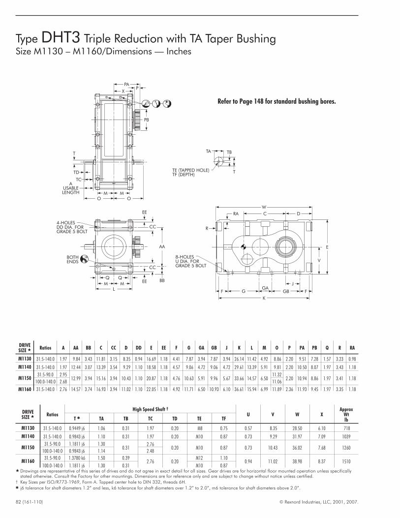
82 (161-110) © Rexnord Industries, LLC, 2001, 2007.
TA TB
TTE (TAPPED HOLE)TF (DEPTH)
T
TD
TC
X
OO
AUSABLELENGTH
PPA
PB
MM
AA
4-HOLESDD DIA. FORGRADE 5 BOLT
BBEE
CC
EE
CC
LMM
Q Q
BOTHENDS
W
C D
V
E
F
8-HOLESU DIA. FORGRADE 5 BOLT
GGA
GB F
K
J
R
RA
Type DHT3 Triple Reduction with TA Taper BushingSize M1130 – M1160/Dimensions — Inches
Refer to Page 148 for standard bushing bores.
DRIVESIZE � Ratios A AA BB C CC D DD E EE F G GA GB J K L M O P PA PB Q R RA
M1130 31.5-140.0 1.97 9.84 3.43 11.81 3.15 8.35 0.94 16.69 1.18 4.41 7.87 3.94 7.87 3.94 26.14 11.42 4.92 8.86 2.20 9.51 7.28 1.57 3.23 0.98
M1140 31.5-140.0 1.97 12.44 3.07 13.39 3.54 9.29 1.10 18.58 1.18 4.57 9.06 4.72 9.06 4.72 29.61 13.39 5.91 9.81 2.20 10.50 8.07 1.97 3.43 1.18
M115031.5-90.0 2.95
12.99 3.94 15.16 3.94 10.43 1.10 20.87 1.18 4.76 10.63 5.91 9.96 5.67 33.66 14.57 6.5011.32
2.20 10.94 8.86 1.97 3.41 1.18100.0-140.0 2.68 11.06
M1160 31.5-140.0 2.76 14.57 3.74 16.93 3.94 11.02 1.10 22.05 1.18 4.92 11.71 6.50 10.93 6.10 36.61 15.94 6.99 11.89 2.36 11.93 9.45 1.97 3.35 1.18
DRIVESIZE � Ratios
High Speed Shaft †
U V W XApprox
WtlbT � TA TB TC TD TE TF
M1130 31.5-140.0 0.9449 j6 1.06 0.31 1.97 0.20 M8 0.75 0.57 8.35 28.50 6.10 718
M1140 31.5-140.0 0.9843 j6 1.10 0.31 1.97 0.20 M10 0.87 0.73 9.29 31.97 7.09 1039
M115031.5-90.0 1.1811 j6 1.30
0.312.76
0.20 M10 0.87 0.73 10.43 36.02 7.68 1260100.0-140.0 0.9843 j6 1.14 2.48
M116031.5-90.0 1.3780 k6 1.50 0.39
2.76 0.20M12 1.10
0.94 11.02 38.98 8.37 1510100.0-140.0 1.1811 j6 1.30 0.31 M10 0.87
� Drawings are representative of this series of drives and do not agree in exact detail for all sizes. Gear drives are for horizontal floor mounted operation unless specificallystated otherwise. Consult the Factory for other mountings. Dimensions are for reference only and are subject to change without notice unless certified.
† Key Sizes per ISO/R773-1969, Form A. Tapped center hole to DIN 332, threads 6H.� j6 tolerance for shaft diameters 1.2” and less, k6 tolerance for shaft diameters over 1.2” to 2.0”, m6 tolerance for shaft diameters above 2.0”.
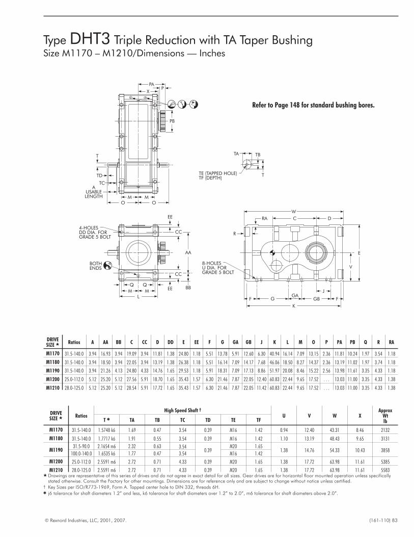
© Rexnord Industries, LLC, 2001, 2007. (161-110) 83
TA TB
TTE (TAPPED HOLE)TF (DEPTH)
T
TD
TC
X
OO
AUSABLELENGTH
PPA
PB
MM
AA
4-HOLESDD DIA. FORGRADE 5 BOLT
BBEE
CC
EE
CC
LMM
Q Q
BOTHENDS
W
C D
V
E
F
8-HOLESU DIA. FORGRADE 5 BOLT
GGA
GB F
K
J
R
RA
Type DHT3 Triple Reduction with TA Taper BushingSize M1170 – M1210/Dimensions — Inches
Refer to Page 148 for standard bushing bores.
DRIVESIZE � Ratios A AA BB C CC D DD E EE F G GA GB J K L M O P PA PB Q R RA
M1170 31.5-140.0 3.94 16.93 3.94 19.09 3.94 11.81 1.38 24.80 1.18 5.51 13.78 5.91 12.60 6.30 40.94 16.14 7.09 13.15 2.36 11.81 10.24 1.97 3.54 1.18
M1180 31.5-140.0 3.94 18.50 3.94 22.05 3.94 13.19 1.38 26.38 1.18 5.51 16.14 7.09 14.17 7.68 46.06 18.50 8.27 14.37 2.36 13.19 11.02 1.97 3.74 1.18
M1190 31.5-140.0 3.94 21.26 4.13 24.80 4.33 14.76 1.65 29.53 1.18 5.91 18.31 7.09 17.13 8.86 51.97 20.08 8.46 15.22 2.56 13.98 11.61 3.35 4.33 1.18
M1200 25.0-112.0 5.12 25.20 5.12 27.56 5.91 18.70 1.65 35.43 1.57 6.30 21.46 7.87 22.05 12.40 60.83 22.44 9.65 17.52 . . . 13.03 11.00 3.35 4.33 1.38
M1210 28.0-125.0 5.12 25.20 5.12 28.54 5.91 17.72 1.65 35.43 1.57 6.30 21.46 7.87 22.05 11.42 60.83 22.44 9.65 17.52 . . . 13.03 11.00 3.35 4.33 1.38
DRIVESIZE � Ratios
High Speed Shaft †
U V W XApprox
WtlbT � TA TB TC TD TE TF
M1170 31.5-140.0 1.5748 k6 1.69 0.47 3.54 0.39 M16 1.42 0.94 12.40 43.31 8.46 2132
M1180 31.5-140.0 1.7717 k6 1.91 0.55 3.54 0.39 M16 1.42 1.10 13.19 48.43 9.65 3131
M119031.5-90.0 2.1654 m6 2.32 0.63 3.54
0.39M20 1.65
1.38 14.76 54.33 10.43 3858100.0-140.0 1.6535 k6 1.77 0.47 3.54 M16 1.42
M1200 25.0-112.0 2.5591 m6 2.72 0.71 4.33 0.39 M20 1.65 1.38 17.72 63.98 11.61 5385
M1210 28.0-125.0 2.5591 m6 2.72 0.71 4.33 0.39 M20 1.65 1.38 17.72 63.98 11.61 5583� Drawings are representative of this series of drives and do not agree in exact detail for all sizes. Gear drives are for horizontal floor mounted operation unless specifically
stated otherwise. Consult the Factory for other mountings. Dimensions are for reference only and are subject to change without notice unless certified.† Key Sizes per ISO/R773-1969, Form A. Tapped center hole to DIN 332, threads 6H.� j6 tolerance for shaft diameters 1.2” and less, k6 tolerance for shaft diameters over 1.2” to 2.0”, m6 tolerance for shaft diameters above 2.0”.
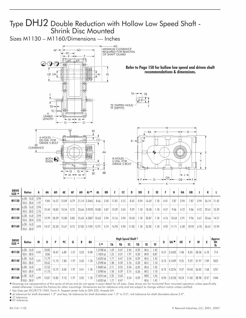
84 (161-110) © Rexnord Industries, LLC, 2001, 2007.
Type DHJ2 Double Reduction with Hollow Low Speed Shaft -Shrink Disc Mounted
Sizes M1130 – M1160/Dimensions — Inches
TA TB
TTE (TAPPED HOLE)TF (DEPTH)
T
TD
TC
X
OO
AUSABLELENGTH
PC
MM
AA
4-HOLESDD DIA. FORGRADE 5 BOLT
BBEE
CC
EE
CC
LMM
Q Q
BOTHENDS
W
C D
V
E
F
8-HOLESU DIA. FORGRADE 5 BOLT
GGA
GB F
K
J
R
RA
P
ADAF MINIMUM CLEARANCEREQUIRED FOR REMOVALOF SHAFT GUARD
AG
UAUE AJ AL
AECLEARANCE
DRIVESIZE � Ratios A AA AD AE AF AG AJ � AL BB C CC D DD E EE F G GA GB J K L
M11306.30 - 16.0 3.94
9.84 16.57 12.09 0.79 21.14 3.3465 8.66 3.43 11.81 3.15 8.35 0.94 16.69 1.18 4.41 7.87 3.94 7.87 3.94 26.14 11.4218.0 - 28.0 1.97
M11406.30 - 16.0 3.94
12.44 18.82 13.54 0.75 23.66 3.9370 10.00 3.07 13.39 3.54 9.29 1.10 18.58 1.18 4.57 9.06 4.72 9.06 4.72 29.61 13.3918.0 - 28.0 2.76
M11506.30 - 16.0 3.94
12.99 20.39 15.00 0.83 25.63 4.3307 10.63 3.94 15.16 3.94 10.43 1.10 20.87 1.18 4.76 10.63 5.91 9.96 5.67 33.66 14.5718.0 - 28.0 3.35
M11606.30 - 16.0
3.94 14.57 22.20 15.67 0.75 27.83 5.1181 12.91 3.74 16.93 3.94 11.02 1.10 22.05 1.18 4.92 11.71 6.50 10.93 6.10 36.61 15.9418.0 - 28.0
DRIVESIZE � Ratios M O P PC Q R RA
High Speed Shaft †
U UA � UE V W XApprox
WtlbT � TA TB TC TD TE TF
M11306.30 - 16.0
4.9210.83
10.47 6.89 1.57 3.23 0.981.5748 k6 1.69 0.47 3.54 0.39 M16 1.42
0.57 3.5433 7.48 8.35 28.50 6.10 71418.0 - 28.0 8.86 1.1024 j6 1.22 0.31 1.97 0.20 M10 0.87
M11406.30 - 16.0
5.9111.79
11.73 7.83 1.97 3.43 1.181.6535 k6 1.77 0.47 3.54 0.39 M16 1.42
0.73 4.1339 9.25 9.29 31.97 7.09 102318.0 - 28.0 10.62 1.2598 k6 1.38 0.39 2.76 0.20 M12 1.10
M11506.30 - 16.0
6.5012.52
12.72 8.50 1.97 3.41 1.181.9685 k6 2.11 0.55 3.54 0.39 M16 1.42
0.73 4.5276 9.37 10.43 36.02 7.68 125718.0 - 28.0 11.73 1.3780 k6 1.50 0.39 3.15 0.20 M12 1.10
M11606.30 - 16.0
6.99 13.07 13.82 9.13 1.97 3.35 1.182.1654 m6 2.32 0.63
3.54 0.39M20 1.65
0.94 5.3150 10.24 11.02 38.98 8.37 144418.0 - 28.0 1.6535 k6 1.77 0.47 M16 1.42
� Drawings are representative of this series of drives and do not agree in exact detail for all sizes. Gear drives are for horizontal floor mounted operation unless specificallystated otherwise. Consult the Factory for other mountings. Dimensions are for reference only and are subject to change without notice unless certified.
† Key Sizes per ISO/R773-1969, Form A. Tapped center hole to DIN 332, threads 6H.� j6 tolerance for shaft diameters 1.2” and less, k6 tolerance for shaft diameters over 1.2” to 2.0”, m6 tolerance for shaft diameters above 2.0”.� J7 tolerance.� H7 tolerance.
Refer to Page 150 for hollow low speed and driven shaftrecommendations & dimensions.

© Rexnord Industries, L.L.C., 2001, 2007. (161-110) 85
Type DHJ2 Double Reduction with Hollow Low Speed Shaft -Shrink Disc Mounted
Sizes M1170 – M1210/Dimensions — Inches
TA TB
TTE (TAPPED HOLE)TF (DEPTH)
T
TD
TC
X
OO
AUSABLELENGTH
PC
MM
AA
4-HOLESDD DIA. FORGRADE 5 BOLT
BBEE
CC
EE
CC
LMM
Q Q
BOTHENDS
W
C D
V
E
F
8-HOLESU DIA. FORGRADE 5 BOLT
GGA
GB F
K
J
R
RA
P
ADAF MINIMUM CLEARANCEREQUIRED FOR REMOVALOF SHAFT GUARD
AG
UAUE AJ AL
AECLEARANCE
Refer to Page 150 for hollow low speed and driven shaftrecommendations & dimensions.
DRIVESIZE � Ratios A AA AD AE AF AG AJ � AL BB C CC D DD E EE F G GA GB J K L
M11706.30 - 16.0 4.92
16.93 22.44 18.31 0.83 28.15 5.5118 13.86 3.94 19.09 3.94 11.81 1.38 24.80 1.18 5.51 13.78 5.91 12.60 6.30 40.94 16.1418.0 - 28.0 3.74
M11806.30 - 16.0
5.12 18.50 25.98 19.96 0.79 32.87 6.4961 15.75 3.94 22.05 3.94 13.19 1.38 26.38 1.18 5.51 16.14 7.09 14.17 7.68 46.06 18.5018.0 - 28.0
M11906.30 - 16.0 6.10
21.26 27.83 23.46 0.91 34.84 7.0866 17.28 4.13 24.80 4.33 14.76 1.65 29.53 1.18 5.91 18.31 7.09 17.13 8.86 51.97 20.0818.0 - 28.0 4.72
M12005.00 - 12.5 6.10
25.20 30.98 29.57 0.87 38.27 7.8740 18.70 5.12 27.56 5.91 18.70 1.65 35.43 1.57 6.30 21.46 7.87 22.05 12.40 60.83 22.4414.0 - 22.4 6.30
M12105.60 - 14.0 6.10
25.20 30.98 29.57 0.87 38.27 7.8740 18.70 5.12 28.54 5.91 17.72 1.65 35.43 1.57 6.30 21.46 7.87 22.05 11.42 60.83 22.4416.0 - 25.0 6.30
DRIVESIZE � Ratios M O P PC Q R RA
High Speed Shaft †
U UA � UE V W XApprox
WtlbT � TA TB TC TD TE TF
M11706.30 - 16.0
7.0914.33
13.98 9.29 1.97 3.54 1.182.5591 m6 2.72 0.71 4.33
0.39M20 1.65
0.94 5.7087 11.42 12.40 43.31 8.46 213218.0 - 28.0 13.15 1.9685 k6 2.11 0.55 3.54 M16 1.42
M11806.30 - 16.0
8.27 15.55 16.34 10.43 1.97 3.74 1.182.7559 m6 2.93 0.79
4.33 0.39 M20 1.65 1.10 6.6929 13.78 13.19 48.43 9.65 308618.0 - 28.0 2.3622 m6 2.52 0.71
M11906.30 - 16.0
8.4617.52
17.40 11.34 3.35 4.33 1.183.1496 m6 3.35 0.87 5.51 0.59
M20 1.65 1.38 7.2835 14.57 14.76 54.33 10.43 374818.0 - 28.0 16.34 2.7559 m6 2.93 0.79 4.33 0.39
M12005.00 - 12.5
9.65 18.70 19.37 12.48 3.35 4.33 1.383.3465 m6 3.54
0.87 5.51 0.59 M20 1.65 1.38 8.2677 15.35 17.72 63.98 11.61 531114.0 - 22.4 3.1496 m6 3.35
M12105.60 - 14.0
9.65 18.70 19.37 12.48 3.35 4.33 1.383.3465 m6 3.54
0.87 5.51 0.59 M20 1.65 1.38 8.2677 15.35 17.72 63.98 11.61 550916.0 - 25.0 3.1496 m6 3.35
� See fotenotes on Page 64.
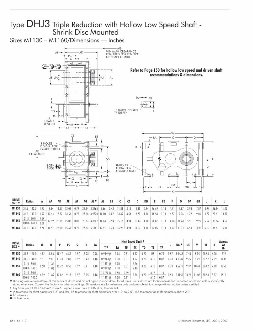
86 (161-110) © Rexnord Industries, LLC, 2001, 2007.
Type DHJ3 Triple Reduction with Hollow Low Speed Shaft -Shrink Disc Mounted
Sizes M1130 – M1160/Dimensions — Inches
TA TB
TTE (TAPPED HOLE)TF (DEPTH)
T
TD
TC
X
OO
AUSABLELENGTH
PC
MM
AA
4-HOLESDD DIA. FORGRADE 5 BOLT
BBEE
CC
EE
CC
LMM
Q Q
BOTHENDS
W
C D
V
E
F
8-HOLESU DIA. FORGRADE 5 BOLT
GGA
GB F
K
J
R
RA
P
ADAF MINIMUM CLEARANCEREQUIRED FOR REMOVALOF SHAFT GUARD
AG
UAUE AJ AL
AECLEARANCE
DRIVESIZE � Ratios A AA AD AE AF AG AJ � AL BB C CC D DD E EE F G GA GB J K L
M1130 31.5 - 140.0 1.97 9.84 16.57 12.09 0.79 21.14 3.3465 8.66 3.43 11.81 3.15 8.35 0.94 16.69 1.18 4.41 7.87 3.94 7.87 3.94 26.14 11.42
M1140 31.5 - 140.0 1.97 12.44 18.82 13.54 0.75 23.66 3.9370 10.00 3.07 13.39 3.54 9.29 1.10 18.58 1.18 4.57 9.06 4.72 9.06 4.72 29.61 13.39
M115031.5 - 90.0 2.95
12.99 20.39 15.00 0.83 25.63 4.3307 10.63 3.94 15.16 3.94 10.43 1.10 20.87 1.18 4.76 10.63 5.91 9.96 5.67 33.66 14.57100.0 - 140.0 2.68
M1160 31.5 - 140.0 2.76 14.57 22.20 15.67 0.75 27.83 5.1181 12.91 3.74 16.93 3.94 11.02 1.10 22.05 1.18 4.92 11.71 6.50 10.93 6.10 36.61 15.94
DRIVESIZE � Ratios M O P PC Q R RA
High Speed Shaft †
U UA � UE V W XApprox
WtlbT � TA TB TC TD TE TF
M1130 31.5 - 140.0 4.92 8.86 10.47 6.89 1.57 3.23 0.98 0.9449 j6 1.06 0.31 1.97 0.20 M8 0.75 0.57 3.5433 7.48 8.35 28.50 6.10 719
M1140 31.5 - 140.0 5.91 9.81 11.73 7.83 1.97 3.43 1.18 0.9843 j6 1.10 0.31 1.97 0.20 M10 0.87 0.73 4.1339 9.25 9.29 31.97 7.09 1038
M115031.5 - 90.0
6.5011.32
12.72 8.50 1.97 3.41 1.181.1811 j6 1.30
0.312.76
0.20 M10 0.87 0.73 4.5276 9.37 10.43 36.02 7.68 1268100.0 - 140.0 11.06 0.9843 j6 1.10 2.48
M116031.5 - 90.0
6.99 11.89 13.82 9.13 1.97 3.35 1.181.3780 k6 1.50 0.39
2.76 0.20M12 1.10
0.94 5.3150 10.24 11.02 38.98 8.37 1510100.0 - 140.0 1.1811 j6 1.30 0.31 M10 0.87
� Drawings are representative of this series of drives and do not agree in exact detail for all sizes. Gear drives are for horizontal floor mounted operation unless specificallystated otherwise. Consult the Factory for other mountings. Dimensions are for reference only and are subject to change without notice unless certified.
† Key Sizes per ISO/R773-1969, Form A. Tapped center hole to DIN 332, threads 6H.� j6 tolerance for shaft diameters 1.2” and less, k6 tolerance for shaft diameters over 1.2” to 2.0”, m6 tolerance for shaft diameters above 2.0”.� J7 tolerance.� H7 tolerance.
Refer to Page 150 for hollow low speed and driven shaftrecommendations & dimensions.
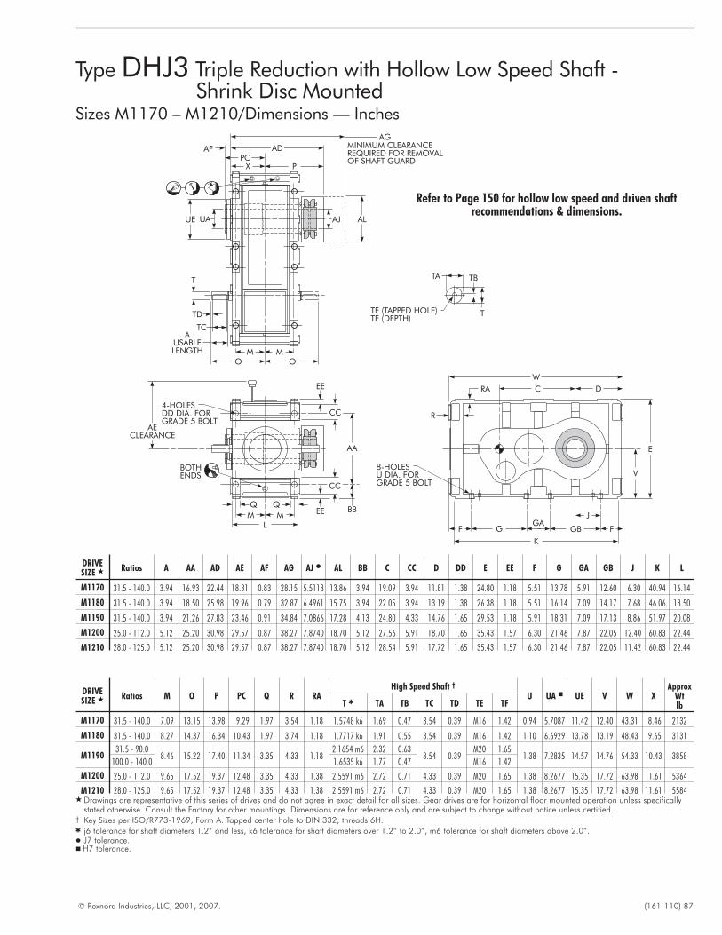
© Rexnord Industries, LLC, 2001, 2007. (161-110) 87
Type DHJ3 Triple Reduction with Hollow Low Speed Shaft -Shrink Disc Mounted
Sizes M1170 – M1210/Dimensions — Inches
TA TB
TTE (TAPPED HOLE)TF (DEPTH)
T
TD
TC
X
OO
AUSABLELENGTH
PC
MM
AA
4-HOLESDD DIA. FORGRADE 5 BOLT
BBEE
CC
EE
CC
LMM
Q Q
BOTHENDS
W
C D
V
E
F
8-HOLESU DIA. FORGRADE 5 BOLT
GGA
GB F
K
J
R
RA
P
ADAF MINIMUM CLEARANCEREQUIRED FOR REMOVALOF SHAFT GUARD
AG
UAUE AJ AL
AECLEARANCE
DRIVESIZE � Ratios A AA AD AE AF AG AJ � AL BB C CC D DD E EE F G GA GB J K L
M1170 31.5 - 140.0 3.94 16.93 22.44 18.31 0.83 28.15 5.5118 13.86 3.94 19.09 3.94 11.81 1.38 24.80 1.18 5.51 13.78 5.91 12.60 6.30 40.94 16.14
M1180 31.5 - 140.0 3.94 18.50 25.98 19.96 0.79 32.87 6.4961 15.75 3.94 22.05 3.94 13.19 1.38 26.38 1.18 5.51 16.14 7.09 14.17 7.68 46.06 18.50
M1190 31.5 - 140.0 3.94 21.26 27.83 23.46 0.91 34.84 7.0866 17.28 4.13 24.80 4.33 14.76 1.65 29.53 1.18 5.91 18.31 7.09 17.13 8.86 51.97 20.08
M1200 25.0 - 112.0 5.12 25.20 30.98 29.57 0.87 38.27 7.8740 18.70 5.12 27.56 5.91 18.70 1.65 35.43 1.57 6.30 21.46 7.87 22.05 12.40 60.83 22.44
M1210 28.0 - 125.0 5.12 25.20 30.98 29.57 0.87 38.27 7.8740 18.70 5.12 28.54 5.91 17.72 1.65 35.43 1.57 6.30 21.46 7.87 22.05 11.42 60.83 22.44
DRIVESIZE � Ratios M O P PC Q R RA
High Speed Shaft †
U UA � UE V W XApprox
WtlbT � TA TB TC TD TE TF
M1170 31.5 - 140.0 7.09 13.15 13.98 9.29 1.97 3.54 1.18 1.5748 k6 1.69 0.47 3.54 0.39 M16 1.42 0.94 5.7087 11.42 12.40 43.31 8.46 2132
M1180 31.5 - 140.0 8.27 14.37 16.34 10.43 1.97 3.74 1.18 1.7717 k6 1.91 0.55 3.54 0.39 M16 1.42 1.10 6.6929 13.78 13.19 48.43 9.65 3131
M119031.5 - 90.0
8.46 15.22 17.40 11.34 3.35 4.33 1.182.1654 m6 2.32 0.63
3.54 0.39M20 1.65
1.38 7.2835 14.57 14.76 54.33 10.43 3858100.0 - 140.0 1.6535 k6 1.77 0.47 M16 1.42
M1200 25.0 - 112.0 9.65 17.52 19.37 12.48 3.35 4.33 1.38 2.5591 m6 2.72 0.71 4.33 0.39 M20 1.65 1.38 8.2677 15.35 17.72 63.98 11.61 5364
M1210 28.0 - 125.0 9.65 17.52 19.37 12.48 3.35 4.33 1.38 2.5591 m6 2.72 0.71 4.33 0.39 M20 1.65 1.38 8.2677 15.35 17.72 63.98 11.61 5584� Drawings are representative of this series of drives and do not agree in exact detail for all sizes. Gear drives are for horizontal floor mounted operation unless specifically
stated otherwise. Consult the Factory for other mountings. Dimensions are for reference only and are subject to change without notice unless certified.† Key Sizes per ISO/R773-1969, Form A. Tapped center hole to DIN 332, threads 6H.� j6 tolerance for shaft diameters 1.2” and less, k6 tolerance for shaft diameters over 1.2” to 2.0”, m6 tolerance for shaft diameters above 2.0”.� J7 tolerance.� H7 tolerance.
Refer to Page 150 for hollow low speed and driven shaftrecommendations & dimensions.
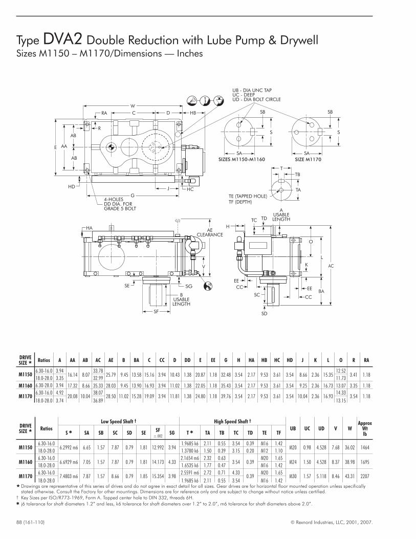
88 (161-110) © Rexnord Industries, LLC, 2001, 2007.
Type DVA2 Double Reduction with Lube Pump & DrywellSizes M1150 – M1170/Dimensions — Inches
TDTC
AUSABLELENGTH
O
EE
K
EE
CC
CCSG
V
D
TE (TAPPED HOLE)TF (DEPTH)
TA
TB
H
BA
HA
HB
HCHD
4-HOLESDD DIA. FORGRADE 5 BOLT
AECLEARANCE
BUSABLELENGTH
G
L
W
C
J
AB
AB
AAE
UB - DIA UNC TAPUC - DEEPUD - DIA BOLT CIRCLE
SE
SC
SD
AC
T
SF
S
SA
SB
S
SA
SB
SIZES M1150-M1160 SIZE M1170
R
RA
DRIVESIZE � Ratios A AA AB AC AE B BA C CC D DD E EE G H HA HB HC HD J K L O R RA
M11506.30-16.0 3.94
16.14 8.0733.78
25.79 9.45 13.58 15.16 3.94 10.43 1.38 20.87 1.18 32.48 3.54 2.17 9.53 3.61 3.54 8.66 2.36 15.3512.52
3.41 1.1818.0-28.0 3.35 32.99 11.73
M1160 6.30-28.0 3.94 17.32 8.66 35.33 28.03 9.45 13.90 16.93 3.94 11.02 1.38 22.05 1.18 35.43 3.54 2.17 9.53 3.61 3.54 9.25 2.36 16.73 13.07 3.35 1.18
M11706.30-16.0 4.92
20.08 10.0438.07
28.50 11.02 15.28 19.09 3.94 11.81 1.38 24.80 1.18 39.76 3.54 2.17 9.53 3.61 3.54 10.04 2.36 16.9314.33
3.54 1.1818.0-28.0 3.74 36.89 13.15
DRIVESIZE � Ratios
Low Speed Shaft † High Speed Shaft †
UB UC UD V WApprox
WtlbS � SA SB SC SD SE
SF±.002
SG T � TA TB TC TD TE TF
M11506.30-16.0
6.2992 m6 6.65 1.57 7.87 0.79 1.81 12.992 3.941.9685 k6 2.11 0.55 3.54 0.39 M16 1.42
M20 0.98 4.528 7.68 36.02 146418.0-28.0 1.3780 k6 1.50 0.39 3.15 0.20 M12 1.10
M11606.30-16.0
6.6929 m6 7.05 1.57 7.87 0.79 1.81 14.173 4.332.1654 m6 2.32 0.63
3.54 0.39M20 1.65
M24 1.50 4.528 8.37 38.98 169518.0-28.0 1.6535 k6 1.77 0.47 M16 1.42
M11706.30-16.0
7.4803 m6 7.87 1.57 8.66 0.79 1.85 15.354 3.982.5591 m6 2.72 0.71 4.33
0.39M20 1.65
M30 1.57 5.118 8.46 43.31 220718.0-28.0 1.9685 k6 2.11 0.55 3.54 M16 1.42
� Drawings are representative of this series of drives and do not agree in exact detail for all sizes. Gear drives are for horizontal floor mounted operation unless specificallystated otherwise. Consult the Factory for other mountings. Dimensions are for reference only and are subject to change without notice unless certified.
† Key Sizes per ISO/R773-1969, Form A. Tapped center hole to DIN 332, threads 6H.� j6 tolerance for shaft diameters 1.2” and less, k6 tolerance for shaft diameters over 1.2” to 2.0”, m6 tolerance for shaft diameters above 2.0”.
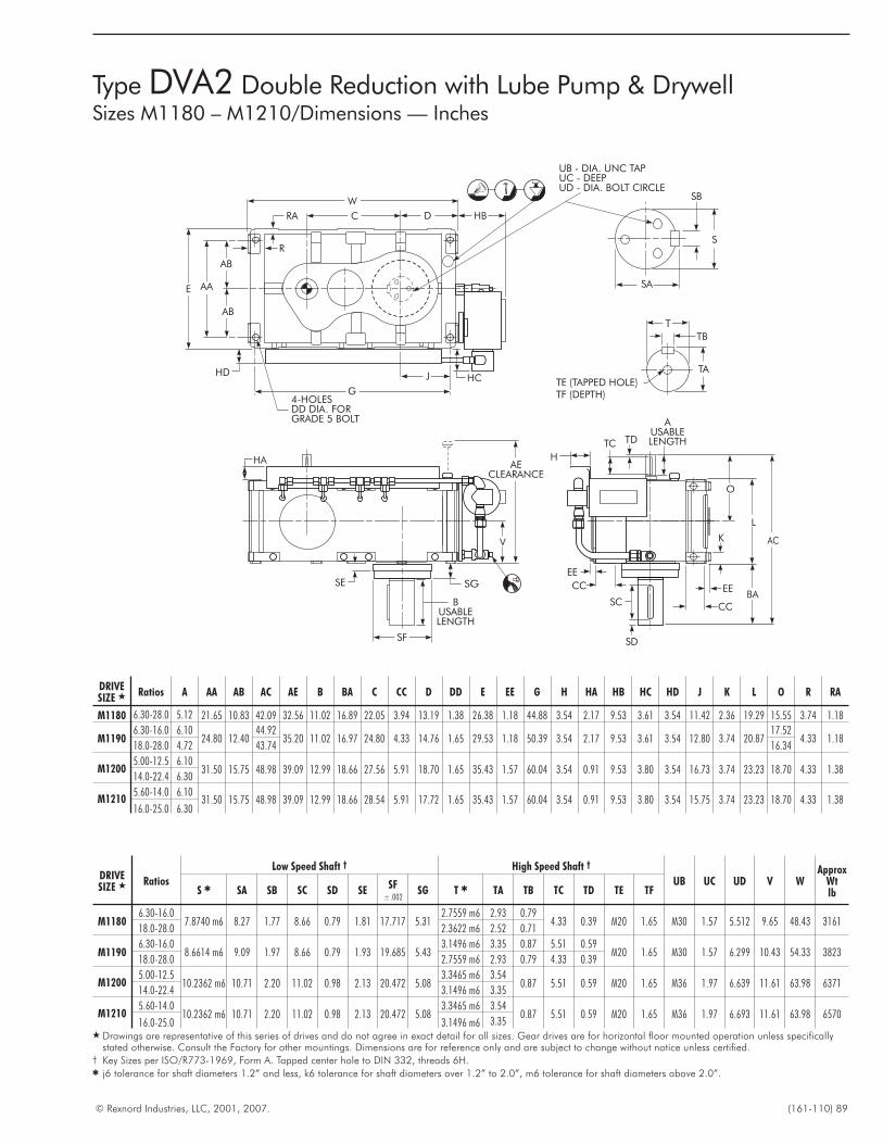
© Rexnord Industries, LLC, 2001, 2007. (161-110) 89
Type DVA2 Double Reduction with Lube Pump & DrywellSizes M1180 – M1210/Dimensions — Inches
TDTC
AUSABLELENGTH
O
EE
K
EE
CC
CCSG
V
D
TE (TAPPED HOLE)TF (DEPTH)
TA
TB
H
BA
HA
HB
HCHD
S
4-HOLESDD DIA. FORGRADE 5 BOLT
AECLEARANCE
SA
BUSABLELENGTH
G
L
W
C
J
AB
AB
AAE
UB - DIA. UNC TAPUC - DEEPUD - DIA. BOLT CIRCLE
SE
SC
SD
AC
T
SF
SB
R
RA
DRIVESIZE � Ratios A AA AB AC AE B BA C CC D DD E EE G H HA HB HC HD J K L O R RA
M1180 6.30-28.0 5.12 21.65 10.83 42.09 32.56 11.02 16.89 22.05 3.94 13.19 1.38 26.38 1.18 44.88 3.54 2.17 9.53 3.61 3.54 11.42 2.36 19.29 15.55 3.74 1.18
M11906.30-16.0 6.10
24.80 12.4044.92
35.20 11.02 16.97 24.80 4.33 14.76 1.65 29.53 1.18 50.39 3.54 2.17 9.53 3.61 3.54 12.80 3.74 20.8717.52
4.33 1.1818.0-28.0 4.72 43.74 16.34
M12005.00-12.5 6.10
31.50 15.75 48.98 39.09 12.99 18.66 27.56 5.91 18.70 1.65 35.43 1.57 60.04 3.54 0.91 9.53 3.80 3.54 16.73 3.74 23.23 18.70 4.33 1.3814.0-22.4 6.30
M12105.60-14.0 6.10
31.50 15.75 48.98 39.09 12.99 18.66 28.54 5.91 17.72 1.65 35.43 1.57 60.04 3.54 0.91 9.53 3.80 3.54 15.75 3.74 23.23 18.70 4.33 1.3816.0-25.0 6.30
DRIVESIZE � Ratios
Low Speed Shaft † High Speed Shaft †
UB UC UD V WApprox
WtlbS � SA SB SC SD SE
SF±.002
SG T � TA TB TC TD TE TF
M11806.30-16.0
7.8740 m6 8.27 1.77 8.66 0.79 1.81 17.717 5.312.7559 m6 2.93 0.79
4.33 0.39 M20 1.65 M30 1.57 5.512 9.65 48.43 316118.0-28.0 2.3622 m6 2.52 0.71
M11906.30-16.0
8.6614 m6 9.09 1.97 8.66 0.79 1.93 19.685 5.433.1496 m6 3.35 0.87 5.51 0.59
M20 1.65 M30 1.57 6.299 10.43 54.33 382318.0-28.0 2.7559 m6 2.93 0.79 4.33 0.39
M12005.00-12.5
10.2362 m6 10.71 2.20 11.02 0.98 2.13 20.472 5.083.3465 m6 3.54
0.87 5.51 0.59 M20 1.65 M36 1.97 6.639 11.61 63.98 637114.0-22.4 3.1496 m6 3.35
M12105.60-14.0
10.2362 m6 10.71 2.20 11.02 0.98 2.13 20.472 5.083.3465 m6 3.54
0.87 5.51 0.59 M20 1.65 M36 1.97 6.693 11.61 63.98 657016.0-25.0 3.1496 m6 3.35
� Drawings are representative of this series of drives and do not agree in exact detail for all sizes. Gear drives are for horizontal floor mounted operation unless specificallystated otherwise. Consult the Factory for other mountings. Dimensions are for reference only and are subject to change without notice unless certified.
† Key Sizes per ISO/R773-1969, Form A. Tapped center hole to DIN 332, threads 6H.� j6 tolerance for shaft diameters 1.2” and less, k6 tolerance for shaft diameters over 1.2” to 2.0”, m6 tolerance for shaft diameters above 2.0”.
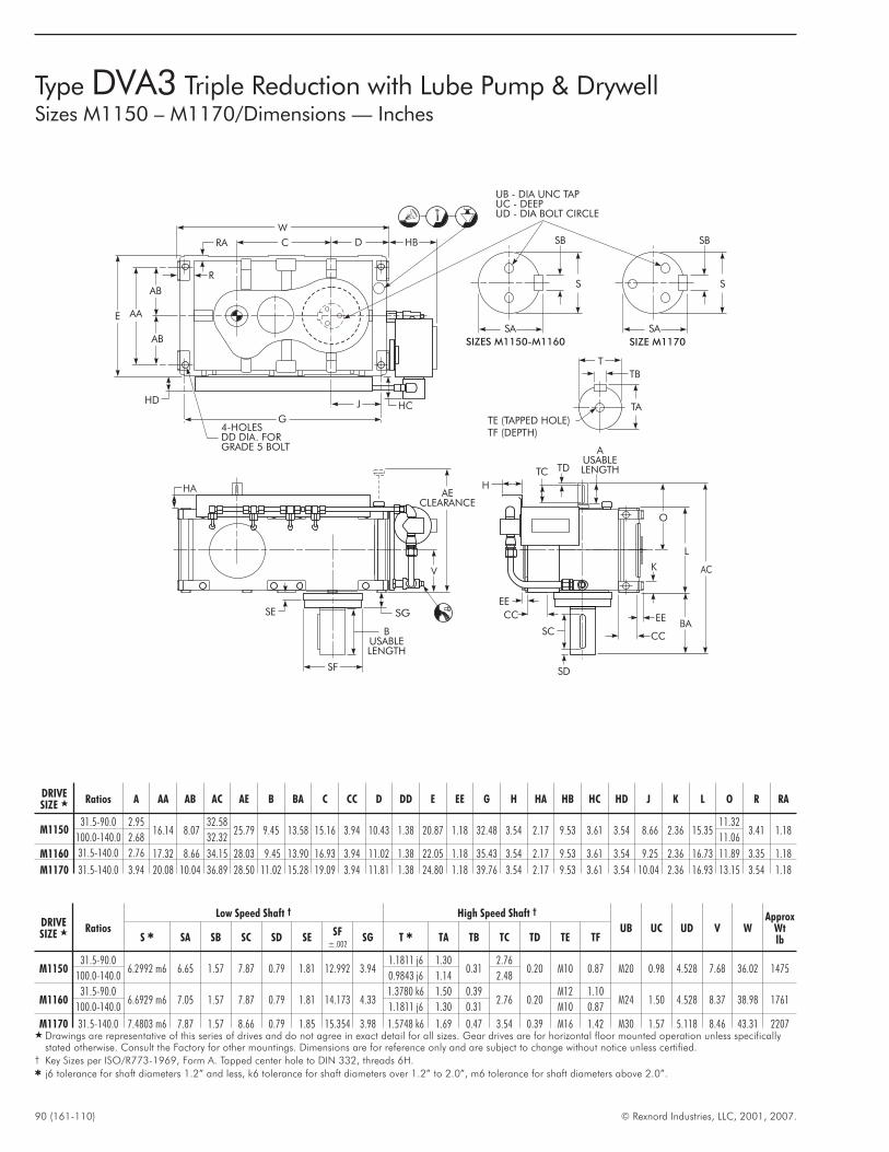
90 (161-110) © Rexnord Industries, LLC, 2001, 2007.
Type DVA3 Triple Reduction with Lube Pump & DrywellSizes M1150 – M1170/Dimensions — Inches
TDTC
AUSABLELENGTH
O
EE
K
EE
CC
CCSG
V
D
TE (TAPPED HOLE)TF (DEPTH)
TA
TB
H
BA
HA
HB
HCHD
4-HOLESDD DIA. FORGRADE 5 BOLT
AECLEARANCE
BUSABLELENGTH
G
L
W
C
J
AB
AB
AAE
UB - DIA UNC TAPUC - DEEPUD - DIA BOLT CIRCLE
SE
SC
SD
AC
T
SF
S
SA
SB
S
SA
SB
SIZES M1150-M1160 SIZE M1170
R
RA
DRIVESIZE � Ratios A AA AB AC AE B BA C CC D DD E EE G H HA HB HC HD J K L O R RA
M115031.5-90.0 2.95
16.14 8.0732.58
25.79 9.45 13.58 15.16 3.94 10.43 1.38 20.87 1.18 32.48 3.54 2.17 9.53 3.61 3.54 8.66 2.36 15.3511.32
3.41 1.18100.0-140.0 2.68 32.32 11.06
M1160 31.5-140.0 2.76 17.32 8.66 34.15 28.03 9.45 13.90 16.93 3.94 11.02 1.38 22.05 1.18 35.43 3.54 2.17 9.53 3.61 3.54 9.25 2.36 16.73 11.89 3.35 1.18
M1170 31.5-140.0 3.94 20.08 10.04 36.89 28.50 11.02 15.28 19.09 3.94 11.81 1.38 24.80 1.18 39.76 3.54 2.17 9.53 3.61 3.54 10.04 2.36 16.93 13.15 3.54 1.18
DRIVESIZE � Ratios
Low Speed Shaft † High Speed Shaft †
UB UC UD V WApprox
WtlbS � SA SB SC SD SE
SF±.002
SG T � TA TB TC TD TE TF
M115031.5-90.0
6.2992 m6 6.65 1.57 7.87 0.79 1.81 12.992 3.941.1811 j6 1.30
0.312.76
0.20 M10 0.87 M20 0.98 4.528 7.68 36.02 1475100.0-140.0 0.9843 j6 1.14 2.48
M116031.5-90.0
6.6929 m6 7.05 1.57 7.87 0.79 1.81 14.173 4.331.3780 k6 1.50 0.39
2.76 0.20M12 1.10
M24 1.50 4.528 8.37 38.98 1761100.0-140.0 1.1811 j6 1.30 0.31 M10 0.87
M1170 31.5-140.0 7.4803 m6 7.87 1.57 8.66 0.79 1.85 15.354 3.98 1.5748 k6 1.69 0.47 3.54 0.39 M16 1.42 M30 1.57 5.118 8.46 43.31 2207� Drawings are representative of this series of drives and do not agree in exact detail for all sizes. Gear drives are for horizontal floor mounted operation unless specifically
stated otherwise. Consult the Factory for other mountings. Dimensions are for reference only and are subject to change without notice unless certified.† Key Sizes per ISO/R773-1969, Form A. Tapped center hole to DIN 332, threads 6H.� j6 tolerance for shaft diameters 1.2” and less, k6 tolerance for shaft diameters over 1.2” to 2.0”, m6 tolerance for shaft diameters above 2.0”.
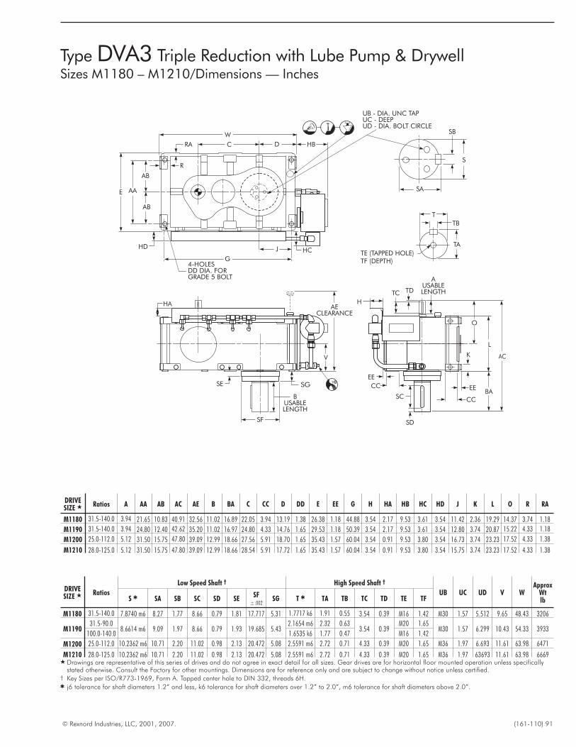
© Rexnord Industries, LLC, 2001, 2007. (161-110) 91
Type DVA3 Triple Reduction with Lube Pump & DrywellSizes M1180 – M1210/Dimensions — Inches
TDTC
AUSABLELENGTH
O
EE
K
EE
CC
CCSG
V
D
TE (TAPPED HOLE)TF (DEPTH)
TA
TB
H
BA
HA
HB
HCHD
S
4-HOLESDD DIA. FORGRADE 5 BOLT
AECLEARANCE
SA
BUSABLELENGTH
G
L
W
C
J
AB
AB
AAE
UB - DIA. UNC TAPUC - DEEPUD - DIA. BOLT CIRCLE
SE
SC
SD
AC
T
SF
SB
R
RA
DRIVESIZE � Ratios A AA AB AC AE B BA C CC D DD E EE G H HA HB HC HD J K L O R RA
M1180 31.5-140.0 3.94 21.65 10.83 40.91 32.56 11.02 16.89 22.05 3.94 13.19 1.38 26.38 1.18 44.88 3.54 2.17 9.53 3.61 3.54 11.42 2.36 19.29 14.37 3.74 1.18
M1190 31.5-140.0 3.94 24.80 12.40 42.62 35.20 11.02 16.97 24.80 4.33 14.76 1.65 29.53 1.18 50.39 3.54 2.17 9.53 3.61 3.54 12.80 3.74 20.87 15.22 4.33 1.18
M1200 25.0-112.0 5.12 31.50 15.75 47.80 39.09 12.99 18.66 27.56 5.91 18.70 1.65 35.43 1.57 60.04 3.54 0.91 9.53 3.80 3.54 16.73 3.74 23.23 17.52 4.33 1.38
M1210 28.0-125.0 5.12 31.50 15.75 47.80 39.09 12.99 18.66 28.54 5.91 17.72 1.65 35.43 1.57 60.04 3.54 0.91 9.53 3.80 3.54 15.75 3.74 23.23 17.52 4.33 1.38
DRIVESIZE � Ratios
Low Speed Shaft † High Speed Shaft †
UB UC UD V WApprox
WtlbS � SA SB SC SD SE
SF±.002
SG T � TA TB TC TD TE TF
M1180 31.5-140.0 7.8740 m6 8.27 1.77 8.66 0.79 1.81 17.717 5.31 1.7717 k6 1.91 0.55 3.54 0.39 M16 1.42 M30 1.57 5.512 9.65 48.43 3206
M119031.5-90.0
8.6614 m6 9.09 1.97 8.66 0.79 1.93 19.685 5.432.1654 m6 2.32 0.63
3.54 0.39M20 1.65
M30 1.57 6.299 10.43 54.33 3933100.0-140.0 1.6535 k6 1.77 0.47 M16 1.42
M1200 25.0-112.0 10.2362 m6 10.71 2.20 11.02 0.98 2.13 20.472 5.08 2.5591 m6 2.72 0.71 4.33 0.39 M20 1.65 M36 1.97 6.693 11.61 63.98 6471
M1210 28.0-125.0 10.2362 m6 10.71 2.20 11.02 0.98 2.13 20.472 5.08 2.5591 m6 2.72 0.71 4.33 0.39 M20 1.65 M36 1.97 63693 11.61 63.98 6669� Drawings are representative of this series of drives and do not agree in exact detail for all sizes. Gear drives are for horizontal floor mounted operation unless specifically
stated otherwise. Consult the Factory for other mountings. Dimensions are for reference only and are subject to change without notice unless certified.† Key Sizes per ISO/R773-1969, Form A. Tapped center hole to DIN 332, threads 6H.� j6 tolerance for shaft diameters 1.2” and less, k6 tolerance for shaft diameters over 1.2” to 2.0”, m6 tolerance for shaft diameters above 2.0”.
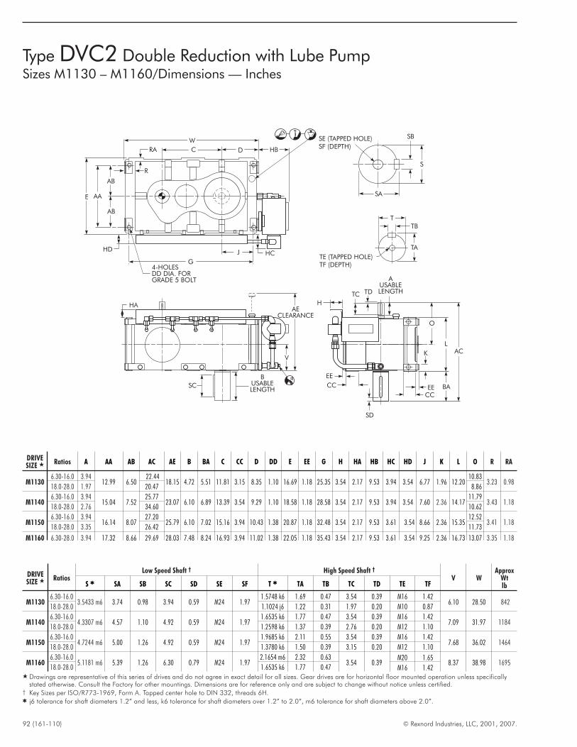
92 (161-110) © Rexnord Industries, LLC, 2001, 2007.
Type DVC2 Double Reduction with Lube PumpSizes M1130 – M1160/Dimensions — Inches
TDTC
AUSABLELENGTH
O
EE
EE
CC
V
D
TE (TAPPED HOLE)TF (DEPTH)
TA
TB
HHA
HB
HCHD
S
4-HOLESDD DIA. FORGRADE 5 BOLT
AECLEARANCE
SB
SA
G
L
W
C
J
AB
AB
AAE
BUSABLELENGTH
SC
SD
AC
BA
SE (TAPPED HOLE)SF (DEPTH)
T
K
CC
R
RA
DRIVESIZE � Ratios A AA AB AC AE B BA C CC D DD E EE G H HA HB HC HD J K L O R RA
M11306.30-16.0 3.94
12.99 6.5022.44
18.15 4.72 5.51 11.81 3.15 8.35 1.10 16.69 1.18 25.35 3.54 2.17 9.53 3.94 3.54 6.77 1.96 12.2010.83
3.23 0.9818.0-28.0 1.97 20.47 8.86
M11406.30-16.0 3.94
15.04 7.5225.77
23.07 6.10 6.89 13.39 3.54 9.29 1.10 18.58 1.18 28.58 3.54 2.17 9.53 3.94 3.54 7.60 2.36 14.1711.79
3.43 1.1818.0-28.0 2.76 34.60 10.62
M11506.30-16.0 3.94
16.14 8.0727.20
25.79 6.10 7.02 15.16 3.94 10.43 1.38 20.87 1.18 32.48 3.54 2.17 9.53 3.61 3.54 8.66 2.36 15.3512.52
3.41 1.1818.0-28.0 3.35 26.42 11.73
M1160 6.30-28.0 3.94 17.32 8.66 29.69 28.03 7.48 8.24 16.93 3.94 11.02 1.38 22.05 1.18 35.43 3.54 2.17 9.53 3.61 3.54 9.25 2.36 16.73 13.07 3.35 1.18
DRIVESIZE � Ratios
Low Speed Shaft † High Speed Shaft †
V WApprox
WtlbS � SA SB SC SD SE SF T � TA TB TC TD TE TF
M11306.30-16.0
3.5433 m6 3.74 0.98 3.94 0.59 M24 1.971.5748 k6 1.69 0.47 3.54 0.39 M16 1.42
6.10 28.50 84218.0-28.0 1.1024 j6 1.22 0.31 1.97 0.20 M10 0.87
M11406.30-16.0
4.3307 m6 4.57 1.10 4.92 0.59 M24 1.971.6535 k6 1.77 0.47 3.54 0.39 M16 1.42
7.09 31.97 118418.0-28.0 1.2598 k6 1.37 0.39 2.76 0.20 M12 1.10
M11506.30-16.0
4.7244 m6 5.00 1.26 4.92 0.59 M24 1.971.9685 k6 2.11 0.55 3.54 0.39 M16 1.42
7.68 36.02 146418.0-28.0 1.3780 k6 1.50 0.39 3.15 0.20 M12 1.10
M11606.30-16.0
5.1181 m6 5.39 1.26 6.30 0.79 M24 1.972.1654 m6 2.32 0.63
3.54 0.39M20 1.65
8.37 38.98 169518.0-28.0 1.6535 k6 1.77 0.47 M16 1.42
� Drawings are representative of this series of drives and do not agree in exact detail for all sizes. Gear drives are for horizontal floor mounted operation unless specificallystated otherwise. Consult the Factory for other mountings. Dimensions are for reference only and are subject to change without notice unless certified.
† Key Sizes per ISO/R773-1969, Form A. Tapped center hole to DIN 332, threads 6H.� j6 tolerance for shaft diameters 1.2” and less, k6 tolerance for shaft diameters over 1.2” to 2.0”, m6 tolerance for shaft diameters above 2.0”.
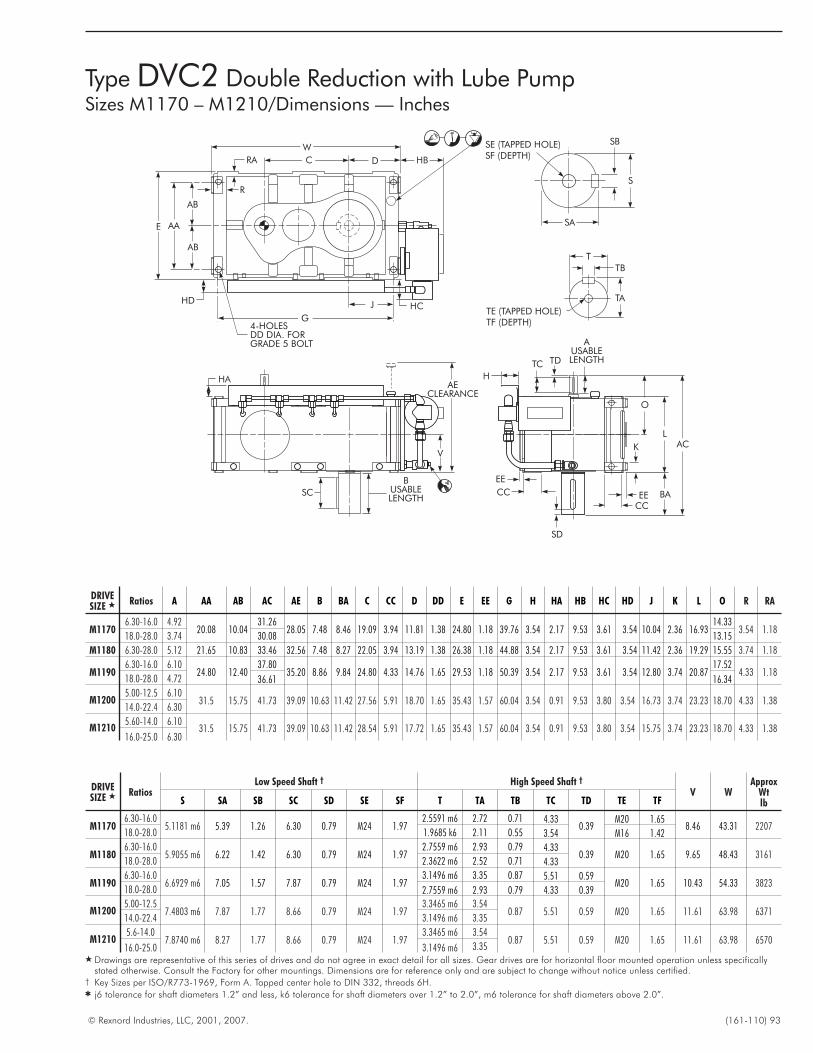
© Rexnord Industries, LLC, 2001, 2007. (161-110) 93
Type DVC2 Double Reduction with Lube PumpSizes M1170 – M1210/Dimensions — Inches
TDTC
AUSABLELENGTH
O
EE
EE
CC
V
D
TE (TAPPED HOLE)TF (DEPTH)
TA
TB
HHA
HB
HCHD
S
4-HOLESDD DIA. FORGRADE 5 BOLT
AECLEARANCE
SB
SA
G
L
W
C
J
AB
AB
AAE
BUSABLELENGTH
SC
SD
AC
BA
SE (TAPPED HOLE)SF (DEPTH)
T
K
CC
R
RA
DRIVESIZE � Ratios A AA AB AC AE B BA C CC D DD E EE G H HA HB HC HD J K L O R RA
M11706.30-16.0 4.92
20.08 10.0431.26
28.05 7.48 8.46 19.09 3.94 11.81 1.38 24.80 1.18 39.76 3.54 2.17 9.53 3.61 3.54 10.04 2.36 16.9314.33
3.54 1.1818.0-28.0 3.74 30.08 13.15
M1180 6.30-28.0 5.12 21.65 10.83 33.46 32.56 7.48 8.27 22.05 3.94 13.19 1.38 26.38 1.18 44.88 3.54 2.17 9.53 3.61 3.54 11.42 2.36 19.29 15.55 3.74 1.18
M11906.30-16.0 6.10
24.80 12.4037.80
35.20 8.86 9.84 24.80 4.33 14.76 1.65 29.53 1.18 50.39 3.54 2.17 9.53 3.61 3.54 12.80 3.74 20.8717.52
4.33 1.1818.0-28.0 4.72 36.61 16.34
M12005.00-12.5 6.10
31.5 15.75 41.73 39.09 10.63 11.42 27.56 5.91 18.70 1.65 35.43 1.57 60.04 3.54 0.91 9.53 3.80 3.54 16.73 3.74 23.23 18.70 4.33 1.3814.0-22.4 6.30
M12105.60-14.0 6.10
31.5 15.75 41.73 39.09 10.63 11.42 28.54 5.91 17.72 1.65 35.43 1.57 60.04 3.54 0.91 9.53 3.80 3.54 15.75 3.74 23.23 18.70 4.33 1.3816.0-25.0 6.30
DRIVESIZE � Ratios
Low Speed Shaft † High Speed Shaft †
V WApprox
WtlbS SA SB SC SD SE SF T TA TB TC TD TE TF
M11706.30-16.0
5.1181 m6 5.39 1.26 6.30 0.79 M24 1.972.5591 m6 2.72 0.71 4.33
0.39M20 1.65
8.46 43.31 220718.0-28.0 1.9685 k6 2.11 0.55 3.54 M16 1.42
M11806.30-16.0
5.9055 m6 6.22 1.42 6.30 0.79 M24 1.972.7559 m6 2.93 0.79 4.33
0.39 M20 1.65 9.65 48.43 316118.0-28.0 2.3622 m6 2.52 0.71 4.33
M11906.30-16.0
6.6929 m6 7.05 1.57 7.87 0.79 M24 1.973.1496 m6 3.35 0.87 5.51 0.59
M20 1.65 10.43 54.33 382318.0-28.0 2.7559 m6 2.93 0.79 4.33 0.39
M12005.00-12.5
7.4803 m6 7.87 1.77 8.66 0.79 M24 1.973.3465 m6 3.54
0.87 5.51 0.59 M20 1.65 11.61 63.98 637114.0-22.4 3.1496 m6 3.35
M12105.6-14.0
7.8740 m6 8.27 1.77 8.66 0.79 M24 1.973.3465 m6 3.54
0.87 5.51 0.59 M20 1.65 11.61 63.98 657016.0-25.0 3.1496 m6 3.35
� Drawings are representative of this series of drives and do not agree in exact detail for all sizes. Gear drives are for horizontal floor mounted operation unless specificallystated otherwise. Consult the Factory for other mountings. Dimensions are for reference only and are subject to change without notice unless certified.
† Key Sizes per ISO/R773-1969, Form A. Tapped center hole to DIN 332, threads 6H.� j6 tolerance for shaft diameters 1.2” and less, k6 tolerance for shaft diameters over 1.2” to 2.0”, m6 tolerance for shaft diameters above 2.0”.
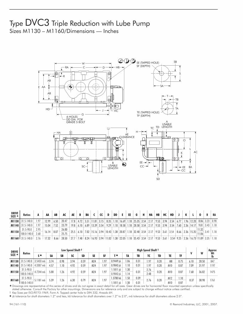
94 (161-110) © Rexnord Industries, LLC, 2001, 2007.
Type DVC3 Triple Reduction with Lube PumpSizes M1130 – M1160/Dimensions — Inches
TDTC
AUSABLELENGTH
O
EE
EE
CC
V
D
TE (TAPPED HOLE)TF (DEPTH)
TA
TB
HHA
HB
HCHD
S
4-HOLESDD DIA. FORGRADE 5 BOLT
AECLEARANCE
SB
SA
G
L
W
C
J
AB
AB
AAE
BUSABLELENGTH
SC
SD
AC
BA
SE (TAPPED HOLE)SF (DEPTH)
T
K
CC
R
RA
DRIVESIZE � Ratios A AA AB AC AE B BA C CC D DD E EE G H HA HB HC HD J K L O R RA
M1130 31.5-140.0 1.97 12.99 6.50 20.47 17.8 4.72 5.51 11.81 3.15 8.35 1.10 16.69 1.18 25.35 3.54 2.17 9.53 3.94 3.54 6.77 1.96 12.20 8.86 3.23 0.98
M1140 31.5-140.0 1.97 15.04 7.52 23.79 19.8 6.10 6.89 13.39 3.54 9.29 1.10 18.58 1.18 28.58 3.54 2.17 9.53 3.94 3.54 7.60 2.36 14.17 9.81 3.43 1.18
M115031.5-90.0 2.95
16.14 8.0726.00
25.5 6.10 7.02 15.16 3.94 10.43 1.38 20.87 1.18 32.48 3.54 2.17 9.53 3.61 3.54 8.66 2.36 15.3511.32
3.41 1.18100.0-140.0 2.68 25.75 11.06
M1160 31.5-140.0 2.76 17.32 8.66 28.50 27.7 7.48 8.24 16.93 3.94 11.02 1.38 22.05 1.18 35.43 3.54 2.17 9.53 3.61 3.54 9.25 2.36 16.73 11.89 3.35 1.18
DRIVESIZE � Ratios
Low Speed Shaft † High Speed Shaft †
V WApprox
WtlbS � SA SB SC SD SE SF T � TA TB TC TD TE TF
M1130 31.5-140.0 3.5433 m6 3.74 0.98 3.94 0.59 M24 1.97 0.9449 j6 1.06 0.31 1.97 0.20 M8 0.75 6.10 28.50 847
M1140 31.5-140.0 4.3307 m6 4.57 1.10 4.92 0.59 M24 1.97 0.9843 j6 1.10 0.31 1.97 0.20 M10 0.87 7.09 31.97 1197
M115031.5-90.0
4.7244 m6 5.00 1.26 4.92 0.59 M24 1.971.1811 j6 1.30
0.312.76
0.20 M10 0.87 7.68 36.02 1475100.0-140.0 0.9843 j6 1.14 2.48
M116031.5-90.0
5.1181 m6 5.39 1.26 6.30 0.79 M24 1.971.3780 k6 1.50 0.39
2.76 0.20M12 1.10
8.37 38.98 1761100.0-140.0 1.1811 j6 1.30 0.31 M10 0.87
� Drawings are representative of this series of drives and do not agree in exact detail for all sizes. Gear drives are for horizontal floor mounted operation unless specificallystated otherwise. Consult the Factory for other mountings. Dimensions are for reference only and are subject to change without notice unless certified.
† Key Sizes per ISO/R773-1969, Form A. Tapped center hole to DIN 332, threads 6H.� j6 tolerance for shaft diameters 1.2” and less, k6 tolerance for shaft diameters over 1.2” to 2.0”, m6 tolerance for shaft diameters above 2.0”.
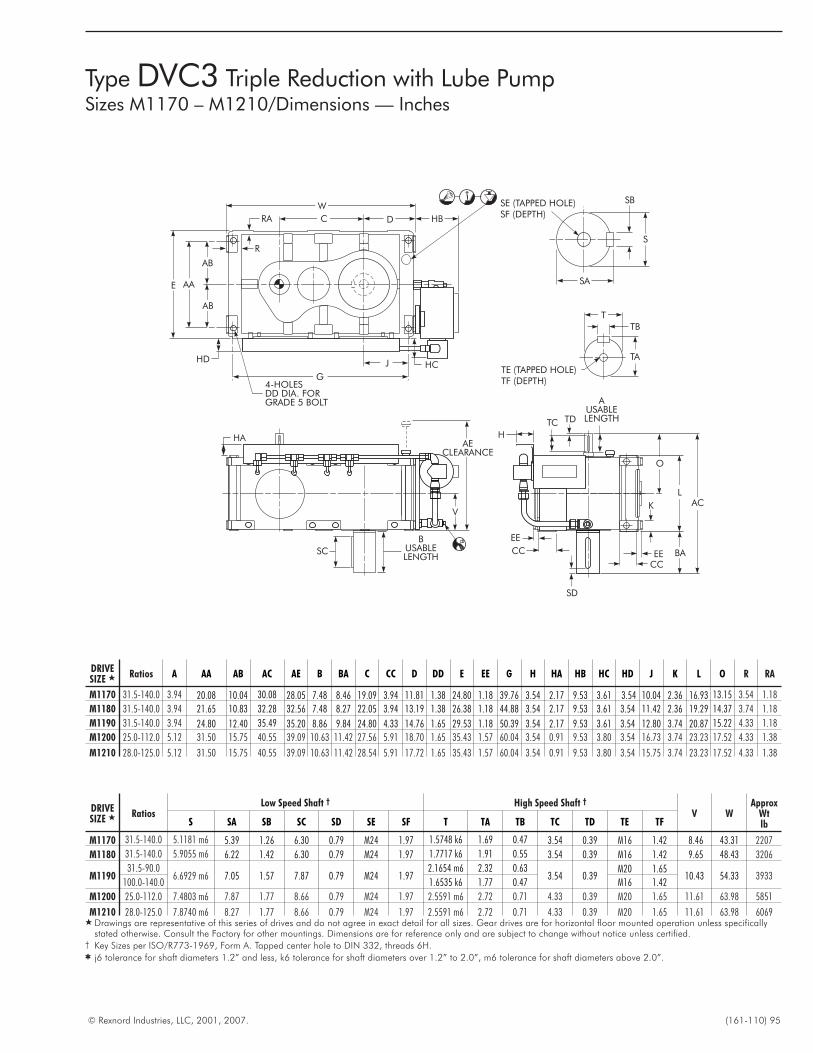
© Rexnord Industries, LLC, 2001, 2007. (161-110) 95
Type DVC3 Triple Reduction with Lube PumpSizes M1170 – M1210/Dimensions — Inches
TDTC
AUSABLELENGTH
O
EE
EE
CC
V
D
TE (TAPPED HOLE)TF (DEPTH)
TA
TB
HHA
HB
HCHD
S
4-HOLESDD DIA. FORGRADE 5 BOLT
AECLEARANCE
SB
SA
G
L
W
C
J
AB
AB
AAE
BUSABLELENGTH
SC
SD
AC
BA
SE (TAPPED HOLE)SF (DEPTH)
T
K
CC
R
RA
DRIVESIZE � Ratios A AA AB AC AE B BA C CC D DD E EE G H HA HB HC HD J K L O R RA
M1170 31.5-140.0 3.94 20.08 10.04 30.08 28.05 7.48 8.46 19.09 3.94 11.81 1.38 24.80 1.18 39.76 3.54 2.17 9.53 3.61 3.54 10.04 2.36 16.93 13.15 3.54 1.18
M1180 31.5-140.0 3.94 21.65 10.83 32.28 32.56 7.48 8.27 22.05 3.94 13.19 1.38 26.38 1.18 44.88 3.54 2.17 9.53 3.61 3.54 11.42 2.36 19.29 14.37 3.74 1.18
M1190 31.5-140.0 3.94 24.80 12.40 35.49 35.20 8.86 9.84 24.80 4.33 14.76 1.65 29.53 1.18 50.39 3.54 2.17 9.53 3.61 3.54 12.80 3.74 20.87 15.22 4.33 1.18
M1200 25.0-112.0 5.12 31.50 15.75 40.55 39.09 10.63 11.42 27.56 5.91 18.70 1.65 35.43 1.57 60.04 3.54 0.91 9.53 3.80 3.54 16.73 3.74 23.23 17.52 4.33 1.38
M1210 28.0-125.0 5.12 31.50 15.75 40.55 39.09 10.63 11.42 28.54 5.91 17.72 1.65 35.43 1.57 60.04 3.54 0.91 9.53 3.80 3.54 15.75 3.74 23.23 17.52 4.33 1.38
DRIVESIZE � Ratios
Low Speed Shaft † High Speed Shaft †
V WApprox
WtlbS SA SB SC SD SE SF T TA TB TC TD TE TF
M1170 31.5-140.0 5.1181 m6 5.39 1.26 6.30 0.79 M24 1.97 1.5748 k6 1.69 0.47 3.54 0.39 M16 1.42 8.46 43.31 2207
M1180 31.5-140.0 5.9055 m6 6.22 1.42 6.30 0.79 M24 1.97 1.7717 k6 1.91 0.55 3.54 0.39 M16 1.42 9.65 48.43 3206
M119031.5-90.0
6.6929 m6 7.05 1.57 7.87 0.79 M24 1.972.1654 m6 2.32 0.63
3.54 0.39M20 1.65
10.43 54.33 3933100.0-140.0 1.6535 k6 1.77 0.47 M16 1.42
M1200 25.0-112.0 7.4803 m6 7.87 1.77 8.66 0.79 M24 1.97 2.5591 m6 2.72 0.71 4.33 0.39 M20 1.65 11.61 63.98 5851
M1210 28.0-125.0 7.8740 m6 8.27 1.77 8.66 0.79 M24 1.97 2.5591 m6 2.72 0.71 4.33 0.39 M20 1.65 11.61 63.98 6069� Drawings are representative of this series of drives and do not agree in exact detail for all sizes. Gear drives are for horizontal floor mounted operation unless specifically
stated otherwise. Consult the Factory for other mountings. Dimensions are for reference only and are subject to change without notice unless certified.† Key Sizes per ISO/R773-1969, Form A. Tapped center hole to DIN 332, threads 6H.� j6 tolerance for shaft diameters 1.2” and less, k6 tolerance for shaft diameters over 1.2” to 2.0”, m6 tolerance for shaft diameters above 2.0”.
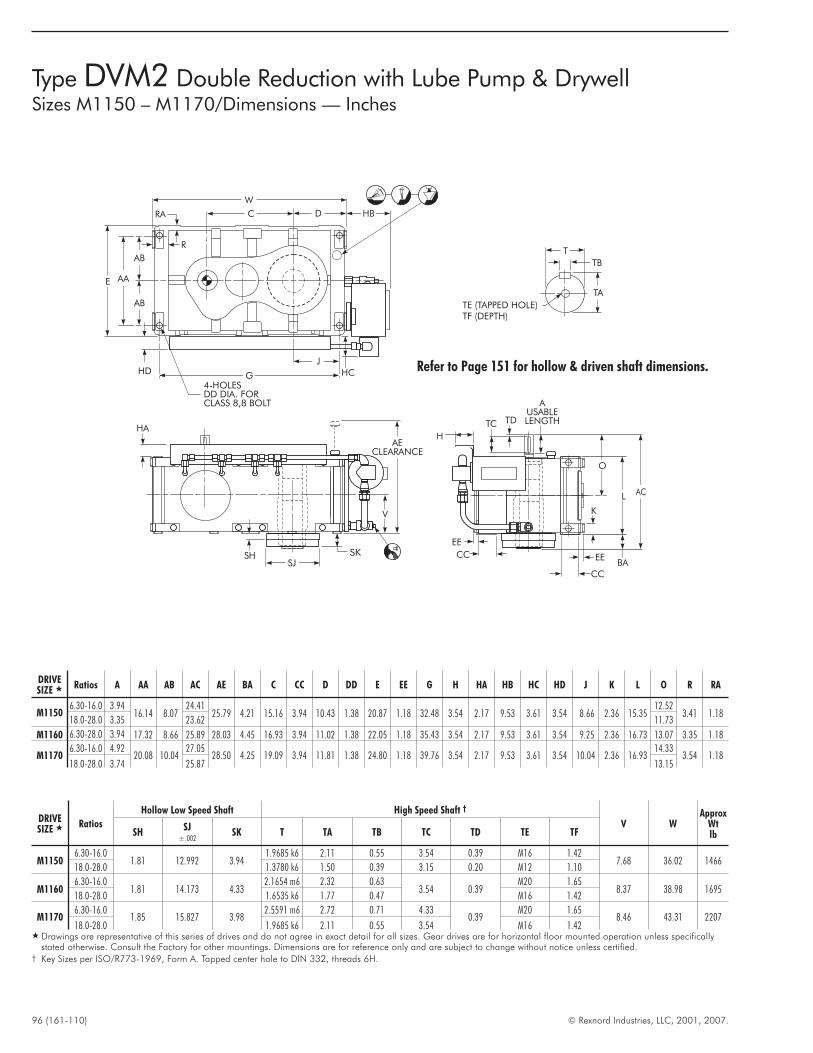
96 (161-110) © Rexnord Industries, LLC, 2001, 2007.
Type DVM2 Double Reduction with Lube Pump & DrywellSizes M1150 – M1170/Dimensions — Inches
TE (TAPPED HOLE)TF (DEPTH)
TA
TB
T
SK
V
HA
AECLEARANCE
SHSJ
D HB
HCHD
4-HOLESDD DIA. FORCLASS 8,8 BOLT
G
W
C
J
AB
AB
AAE
RA
R
AUSABLELENGTHTDTC
O
EE
K
EE
CC
CC
H
BA
L AC
DRIVESIZE � Ratios A AA AB AC AE BA C CC D DD E EE G H HA HB HC HD J K L O R RA
M11506.30-16.0 3.94
16.14 8.0724.41
25.79 4.21 15.16 3.94 10.43 1.38 20.87 1.18 32.48 3.54 2.17 9.53 3.61 3.54 8.66 2.36 15.3512.52
3.41 1.1818.0-28.0 3.35 23.62 11.73
M1160 6.30-28.0 3.94 17.32 8.66 25.89 28.03 4.45 16.93 3.94 11.02 1.38 22.05 1.18 35.43 3.54 2.17 9.53 3.61 3.54 9.25 2.36 16.73 13.07 3.35 1.18
M11706.30-16.0 4.92
20.08 10.0427.05
28.50 4.25 19.09 3.94 11.81 1.38 24.80 1.18 39.76 3.54 2.17 9.53 3.61 3.54 10.04 2.36 16.9314.33
3.54 1.1818.0-28.0 3.74 25.87 13.15
DRIVESIZE � Ratios
Hollow Low Speed Shaft High Speed Shaft †
V WApprox
WtlbSH
SJ±.002
SK T TA TB TC TD TE TF
M11506.30-16.0
1.81 12.992 3.941.9685 k6 2.11 0.55 3.54 0.39 M16 1.42
7.68 36.02 146618.0-28.0 1.3780 k6 1.50 0.39 3.15 0.20 M12 1.10
M11606.30-16.0
1.81 14.173 4.332.1654 m6 2.32 0.63
3.54 0.39M20 1.65
8.37 38.98 169518.0-28.0 1.6535 k6 1.77 0.47 M16 1.42
M11706.30-16.0
1.85 15.827 3.982.5591 m6 2.72 0.71 4.33
0.39M20 1.65
8.46 43.31 220718.0-28.0 1.9685 k6 2.11 0.55 3.54 M16 1.42
� Drawings are representative of this series of drives and do not agree in exact detail for all sizes. Gear drives are for horizontal floor mounted operation unless specificallystated otherwise. Consult the Factory for other mountings. Dimensions are for reference only and are subject to change without notice unless certified.
† Key Sizes per ISO/R773-1969, Form A. Tapped center hole to DIN 332, threads 6H.
Refer to Page 151 for hollow & driven shaft dimensions.
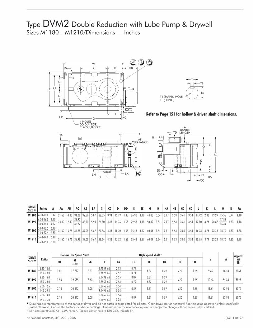
© Rexnord Industries, LLC, 2001, 2007. (161-110) 97
Type DVM2 Double Reduction with Lube Pump & DrywellSizes M1180 – M1210/Dimensions — Inches
TE (TAPPED HOLE)TF (DEPTH)
TA
TB
T
SK
V
HA
AECLEARANCE
SHSJ
D HB
HCHD
4-HOLESDD DIA. FORCLASS 8,8 BOLT
G
W
C
J
AB
AB
AAE
RA
R
AUSABLELENGTHTDTC
O
EE
K
EE
CC
CC
H
BA
L AC
DRIVESIZE � Ratios A AA AB AC AE BA C CC D DD E EE G H HA HB HC HD J K L O R RA
M1180 6.30-28.0 5.12 21.65 10.83 31.06 32.56 5.87 22.05 3.94 13.19 1.38 26.38 1.18 44.88 3.54 2.17 9.53 3.61 3.54 11.42 2.36 19.29 15.55 3.74 1.18
M11906.30-16.0 6.10
24.80 12.4033.90
35.20 5.94 24.80 4.33 14.76 1.65 29.53 1.18 50.39 3.54 2.17 9.53 3.61 3.54 12.80 3.74 20.8717.52
4.33 1.1818.0-28.0 4.72 32.72 16.34
M12005.00-12.5 6.10
31.50 15.75 35.98 39.09 5.67 27.56 4.33 18.70 1.65 35.43 1.57 60.04 3.54 0.91 9.53 3.80 3.54 16.73 3.74 23.23 18.70 4.33 1.3814.0-22.4 6.30
M12105.60-14.0 6.10
31.50 15.75 35.98 39.09 5.67 28.54 4.33 17.72 1.65 35.43 1.57 60.04 3.54 0.91 9.53 3.80 3.54 15.75 3.74 23.23 18.70 4.33 1.3816.0-25.0 6.30
DRIVESIZE � Ratios
Hollow Low Speed Shaft High Speed Shaft †
V WApprox
WtlbSH
SJ±.002
SK T TA TB TC TD TE TF
M11806.30-16.0
1.81 17.717 5.312.7559 m6 2.93 0.79
4.33 0.39 M20 1.65 9.65 48.43 316118.0-28.0 2.3622 m6 2.52 0.71
M11906.30-16.0
1.93 19.685 5.433.1496 m6 3.35 0.87 5.51 0.59
M20 1.65 10.43 54.33 382318.0-28.0 2.7559 m6 2.93 0.79 4.33 0.39
M12005.00-12.5
2.13 20.472 5.083.3465 m6 3.54
0.87 5.51 0.59 M20 1.65 11.61 63.98 637014.0-22.4 3.1496 m6 3.35
M12105.60-14.0
2.13 20.472 5.083.3465 m6 3.54
0.87 5.51 0.59 M20 1.65 11.61 63.98 657016.0-25.0 3.1496 m6 3.35
� Drawings are representative of this series of drives and do not agree in exact detail for all sizes. Gear drives are for horizontal floor mounted operation unless specificallystated otherwise. Consult the Factory for other mountings. Dimensions are for reference only and are subject to change without notice unless certified.
† Key Sizes per ISO/R773-1969, Form A. Tapped center hole to DIN 332, threads 6H.
Refer to Page 151 for hollow & driven shaft dimensions.
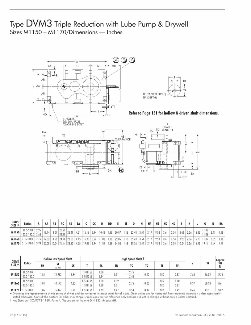
98 (161-110) © Rexnord Industries, LLC, 2001, 2007.
Type DVM3 Triple Reduction with Lube Pump & DrywellSizes M1150 – M1170/Dimensions — Inches
TE (TAPPED HOLE)TF (DEPTH)
TA
TB
T
SK
V
HA
AECLEARANCE
SHSJ
D HB
HCHD
4-HOLESDD DIA. FORCLASS 8,8 BOLT
G
W
C
J
AB
AB
AAE
RA
R
AUSABLELENGTHTDTC
O
EE
K
EE
CC
CC
H
BA
L AC
DRIVESIZE � Ratios A AA AB AC AE BA C CC D DD E EE G H HA HB HC HD J K L O R RA
M115031.5-90.0 2.95
16.14 8.0723.21
25.49 4.21 15.16 3.94 10.43 1.38 20.87 1.18 32.48 3.54 2.17 9.53 3.61 3.54 8.66 2.36 15.3511.32
3.41 1.18100.0-140.0 2.68 22.95 11.06
M1160 31.5-140.0 2.76 17.32 8.66 24.70 28.03 4.45 16.93 3.94 11.02 1.38 22.05 1.18 35.43 3.54 2.17 9.53 3.61 3.54 9.25 2.36 16.73 11.89 3.35 1.18
M1170 31.5-140.0 3.94 20.08 10.04 25.87 28.50 4.25 19.09 3.94 11.81 1.38 24.80 1.18 39.76 3.54 2.17 9.53 3.61 3.54 10.04 2.36 16.93 13.15 3.54 1.18
DRIVESIZE � Ratios
Hollow Low Speed Shaft High Speed Shaft †
V WApprox
WtlbSH
SJ±.002
SK T TA TB TC TD TE TF
M115031.5-90.0
1.81 12.992 3.941.1811 j6 1.30
0.312.76
0.20 M10 0.87 7.68 36.02 1475100.0-140.0 0.9843 j6 1.14 2.48
M116031.5-90.0
1.81 14.173 4.331.3780 k6 1.50 0.39
2.76 0.20M12 1.10
8.37 38.98 1761100.0-140.0 1.1811 j6 1.30 0.31 M10 0.87
M1170 31.5-140.0 1.85 15.827 3.98 1.5748 k6 1.69 0.47 3.54 0.39 M16 1.42 8.46 43.31 2207� Drawings are representative of this series of drives and do not agree in exact detail for all sizes. Gear drives are for horizontal floor mounted operation unless specifically
stated otherwise. Consult the Factory for other mountings. Dimensions are for reference only and are subject to change without notice unless certified.† Key Sizes per ISO/R773-1969, Form A. Tapped center hole to DIN 332, threads 6H.
Refer to Page 151 for hollow & driven shaft dimensions.
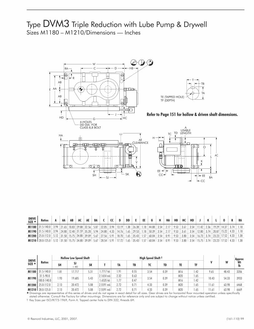
© Rexnord Industries, LLC, 2001, 2007. (161-110) 99
Type DVM3 Triple Reduction with Lube Pump & DrywellSizes M1180 – M1210/Dimensions — Inches
TE (TAPPED HOLE)TF (DEPTH)
TA
TB
T
SK
V
HA
AECLEARANCE
SHSJ
D HB
HCHD
4-HOLESDD DIA. FORCLASS 8,8 BOLT
G
W
C
J
AB
AB
AAE
RA
R
AUSABLELENGTHTDTC
O
EE
K
EE
CC
CC
H
BA
L AC
DRIVESIZE � Ratios A AA AB AC AE BA C CC D DD E EE G H HA HB HC HD J K L O R RA
M1180 31.5-140.0 3.94 21.65 10.83 29.88 32.56 5.87 22.05 3.94 13.19 1.38 26.38 1.18 44.88 3.54 2.17 9.53 3.61 3.54 11.42 2.36 19.29 14.37 3.74 1.18
M1190 31.5-140.0 3.94 24.80 12.40 31.59 35.20 5.94 24.80 4.33 14.76 1.65 29.53 1.18 50.39 3.54 2.17 9.53 3.61 3.54 12.80 3.74 20.87 15.22 4.33 1.18
M1200 25.0-112.0 5.12 31.50 15.75 34.80 39.09 5.67 27.56 5.91 18.70 1.65 35.43 1.57 60.04 3.54 0.91 9.53 3.80 3.54 16.73 3.74 23.23 17.52 4.33 1.38
M1210 28.0-125.0 5.12 31.50 15.75 34.80 39.09 5.67 28.54 5.91 17.72 1.65 35.43 1.57 60.04 3.54 0.91 9.53 3.80 3.54 15.75 3.74 23.23 17.52 4.33 1.38
DRIVESIZE � Ratios
Hollow Low Speed Shaft High Speed Shaft †
V WApprox
WtlbSH
SJ±.002
SK T TA TB TC TD TE TF
M1180 31.5-140.0 1.81 17.717 5.31 1.7717 k6 1.91 0.55 3.54 0.39 M16 1.42 9.65 48.43 3206
M119031.5-90.0
1.93 19.685 5.432.1654 m6 2.32 0.63
3.54 0.39M20 1.65
10.43 54.33 3933100.0-140.0 1.6535 k6 1.77 0.47 M16 1.42
M1200 25.0-112.0 2.13 20.472 5.08 2.5591 m6 2.72 0.71 4.33 0.39 M20 1.65 11.61 63.98 6468
M1210 28.0-125.0 2.13 20.472 5.08 2.5591 m6 2.72 0.71 4.33 0.39 M20 1.65 11.61 63.98 6669� Drawings are representative of this series of drives and do not agree in exact detail for all sizes. Gear drives are for horizontal floor mounted operation unless specifically
stated otherwise. Consult the Factory for other mountings. Dimensions are for reference only and are subject to change without notice unless certified.† Key Sizes per ISO/R773-1969, Form A. Tapped center hole to DIN 332, threads 6H.
Refer to Page 151 for hollow & driven shaft dimensions.
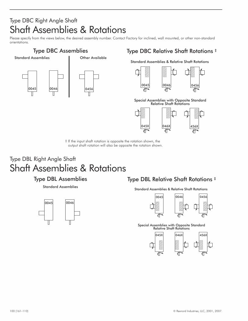
100 (161-110) © Rexnord Industries, LLC, 2001, 2007.
Type DBC Assemblies
00460045 0456
Type DBC Relative Shaft Rotations ‡
Standard Assemblies & Relative Shaft Rotations
Special Assemblies with Opposite StandardRelative Shaft Rotations
00460045 0456
046X045X 456X
Standard Assemblies Other Available
Type DBC Right Angle Shaft
Shaft Assemblies & RotationsPlease specify from the views below, the desired assembly number. Contact Factory for inclined, wall mounted, or other non-standardorientations.
Type DBL Right Angle Shaft
Shaft Assemblies & RotationsType DBL Assemblies Type DBL Relative Shaft Rotations ‡
Standard Assemblies
00460045
Standard Assemblies & Relative Shaft Rotations
Special Assemblies with Opposite StandardRelative Shaft Rotations
0045 0046
045X 046X
0456
456X
‡ If the input shaft rotation is opposite the rotation shown, theoutput shaft rotation will also be opposite the rotation shown.
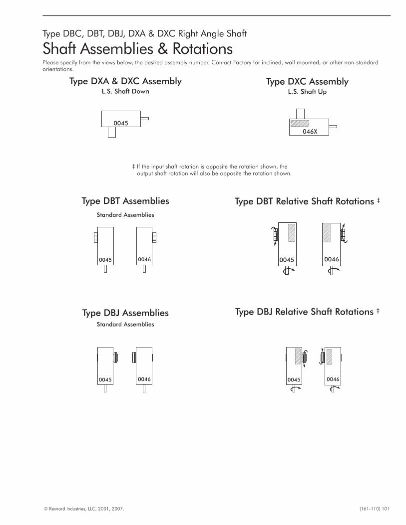
© Rexnord Industries, LLC, 2001, 2007. (161-110) 101
Type DBC, DBT, DBJ, DXA & DXC Right Angle Shaft
Shaft Assemblies & RotationsPlease specify from the views below, the desired assembly number. Contact Factory for inclined, wall mounted, or other non-standardorientations.
0045 0046
Type DBT Assemblies
Standard Assemblies
Type DBT Relative Shaft Rotations ‡
0045 0046
‡ If the input shaft rotation is opposite the rotation shown, theoutput shaft rotation will also be opposite the rotation shown.
Type DBJ AssembliesStandard Assemblies
Type DBJ Relative Shaft Rotations ‡
0045 0046 0045 0046
Type DXA & DXC AssemblyL.S. Shaft Down
Type DXC AssemblyL.S. Shaft Up
0045
046X
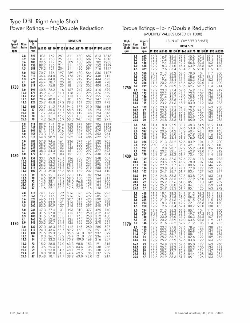
102 (161-110) © Rexnord Industries, LLC, 2001, 2007.
Type DBL Right Angle ShaftPower Ratings – Hp/Double Reduction Torque Ratings – lb-in/Double Reduction
(MULTIPLY VALUES LISTED BY 1000)
HighSpeedShaftrpm
NomRatio
ApproxLS
Shaftrpm
DRIVE SIZE
M1130 M1140 M1150 M1160 M1170 M1180 M1190 M1200
1750
2.8 625 105 162 251 311 430 687 813 13133.2 547 105 153 251 311 430 687 776 13133.6 486 99.5 147 251 309 430 687 782 12834.0 438 89.7 126 211 311 430 609 752 11794.5 389 79.3 121 204 311 430 594 716 1147
5.0 350 70.7 116 197 289 430 564 636 11075.6 313 46.4 84.8 125 173 242 352 448 7126.3 278 46.4 84.8 125 165 242 352 444 6737.1 246 46.4 78.7 125 181 242 352 448 7988.0 219 45.4 75.8 125 181 242 352 404 765
9.0 194 40.5 72.2 116 167 242 352 415 69910.0 175 35.9 61.7 87.1 118 203 295 376 57911.2 156 32.2 52.1 78.6 113 188 272 355 52912.5 140 28.4 48.8 70.5 101 160 252 347 50014.0 125 25.7 45.8 67.2 98.3 161 232 323 473
16.0 109 22.7 41.2 58.3 94.2 137 210 286 41818.0 97 20.1 35.6 54.1 68.8 119 148 194 36520.0 88 17.7 33.4 48.7 68.8 112 148 194 34622.4 78 16.1 31.1 46.6 65.1 103 148 194 32725.0 70 14.2 26.9 36.9 58.3 94.1 142 182 291
1430
2.8 511 89.7 141 216 262 374 597 706 11293.2 447 89.7 133 216 262 374 597 673 11063.6 397 81.3 128 216 253 374 597 679 10484.0 358 73.3 103 172 262 374 498 653 9644.5 318 64.8 98.9 167 262 374 486 622 937
5.0 286 57.8 94.6 161 236 374 461 520 9055.6 255 38.3 70.0 103 141 200 297 377 5826.3 227 38.3 70.0 103 135 200 297 377 5507.1 201 38.3 64.3 103 151 200 297 377 6938.0 179 37.1 61.9 103 151 200 297 330 664
9.0 159 33.1 59.0 95.1 136 200 297 348 60710.0 143 29.3 53.3 75.6 103 176 241 307 50311.2 128 26.3 45.2 68.3 98.3 163 231 290 45912.5 114 23.2 42.3 61.2 87.9 139 219 288 43414.0 102 21.0 39.8 58.3 85.4 132 202 264 410
16.0 89 18.5 35.1 47.6 77.3 119 182 234 36318.0 79 16.5 30.9 46.9 58.0 100 125 164 31120.0 72 14.5 28.1 42.3 58.0 96.8 125 164 30022.4 64 13.1 25.4 38.2 54.2 84.8 125 164 28425.0 57 11.6 22.1 30.2 47.6 77.0 116 148 252
1170
2.8 418 74.1 122 179 216 325 497 606 9233.2 366 73.7 116 179 216 325 497 585 9053.6 325 66.5 111 179 207 311 495 590 8584.0 293 60.0 83.9 141 216 325 407 567 7884.5 260 53.0 80.9 137 216 325 397 540 767
5.0 234 47.3 77.4 131 193 310 377 425 7405.6 209 31.6 57.8 85.3 115 165 250 312 4766.3 186 31.6 57.8 85.3 111 165 250 312 4507.1 165 31.6 52.6 85.3 125 165 250 312 5808.0 146 30.3 50.7 84.4 125 165 250 270 561
9.0 130 27.0 48.3 78.2 112 165 250 285 52710.0 117 24.0 43.6 65.7 89.2 153 197 251 43711.2 104 21.5 39.3 59.3 85.5 141.0 189 237 39912.5 94 19.0 36.7 53.2 76.4 121.0 179 236 37714.0 84 17.2 33.2 49.2 70.9 109.0 168 216 357
16.0 73 15.2 28.8 39.0 63.3 98.8 153 191 31518.0 65 13.5 25.4 40.2 48.8 84.6 105 138 25820.0 59 11.8 23.0 34.7 48.1 79.2 105 138 25822.4 52 10.8 20.8 31.3 44.4 69.5 105 137 23925.0 47 9.48 18.1 24.7 38.9 63.0 95.0 121 217
HighSpeedShaftrpm
NomRatio
ApproxLS
Shaftrpm
(LB-IN AT LOW SPEED SHAFT)
DRIVE SIZE
M1130 M1140 M1150 M1160 M1170 M1180 M1190 M1200
1750
2.8 625 10.9 16.9 26.5 32.8 45.5 70.5 83.7 1373.2 547 12.3 17.6 29.5 36.6 49.9 80.9 88.6 1483.6 486 12.9 19.4 32.5 40.2 56.8 90.5 102 1634.0 438 12.9 18.3 31.0 45.4 63.9 88.8 109 1704.5 389 12.9 19.6 33.4 50.4 71.6 95.0 115 185
5.0 350 12.9 21.3 36.2 52.6 79.0 104 117 2005.6 313 9.51 17.1 25.8 35.1 48.6 72.7 89.8 1406.3 278 10.5 19.6 28.4 37.2 55.3 81.3 103 1497.1 246 11.7 20.2 32.2 45.6 62.2 90.0 114 2008.0 219 12.9 21.6 35.9 50.6 69.7 98.7 114 214
9.0 194 12.9 23.3 37.4 52.6 76.9 114 134 21910.0 175 12.9 22.2 31.0 42.5 73.3 107 134 20311.2 156 12.9 21.6 31.7 46.0 75.8 109 146 20812.5 140 12.9 22.4 32.5 46.2 73.2 115 157 22114.0 125 12.9 23.2 34.6 48.7 83.0 119 163 233
16.0 109 12.6 23.8 33.3 52.3 78.9 118 163 23018.0 97 12.9 23.5 34.4 44.7 75.5 94.1 126 23020.0 88 12.9 24.5 35.4 50.3 80.4 107 138 24422.4 78 12.9 25.2 37.8 51.6 83.9 120 154 25725.0 70 12.6 24.8 33.3 51.7 85.0 126 163 256
1430
2.8 511 11.4 18.0 27.9 33.7 48.3 74.9 88.9 1443.2 447 12.9 18.7 31.1 37.6 53.0 85.9 94.1 1533.6 397 12.9 20.6 34.2 40.2 60.4 96.1 109 1634.0 358 12.9 18.3 31.0 46.7 67.9 88.8 116 1704.5 318 12.9 19.6 33.4 51.8 76.0 95.0 122 185
5.0 286 12.9 21.3 36.2 52.6 83.9 104 117 2005.6 255 9.60 17.3 26.1 35.1 49.1 75.0 92.5 1406.3 227 10.6 19.8 28.7 37.2 55.9 84.0 106 1497.1 201 11.8 20.2 32.5 46.5 62.9 93.0 117 2128.0 179 12.9 21.6 36.2 51.7 70.4 102 114 228
9.0 159 12.9 23.3 37.6 52.6 77.8 118 138 23310.0 143 12.9 23.5 32.9 45.2 78.0 107 134 21611.2 128 12.9 22.9 33.7 48.8 80.6 114 146 22212.5 114 12.9 23.8 34.5 49.1 77.8 122 159 23514.0 102 12.9 24.7 36.7 51.7 83.4 127 163 247
16.0 89 12.6 24.8 33.3 52.5 83.8 125 163 24418.0 79 12.9 25.0 36.5 46.0 77.9 97.0 130 24020.0 72 12.9 25.2 37.6 51.8 85.1 110 142 25922.4 64 12.9 25.2 38.0 52.6 84.1 124 159 27425.0 57 12.6 24.9 33.3 51.7 85.1 126 163 272
1170
2.8 418 11.5 19.1 28.2 34.1 51.3 76.2 93.4 1443.2 366 12.9 19.9 31.5 38.0 56.3 87.5 99.9 1533.6 325 12.9 21.9 34.6 40.2 61.5 97.5 115 1634.0 293 12.9 18.3 31.0 47.2 72.1 88.8 123 1704.5 260 12.9 19.6 33.4 52.4 80.7 95.0 130 185
5.0 234 12.9 21.3 36.2 52.6 85.1 104 117 2005.6 209 9.69 17.5 26.3 35.1 49.7 77.3 93.5 1406.3 186 10.7 20.0 29.0 37.2 56.3 86.5 107 1497.1 165 11.9 20.2 32.9 47.0 63.5 95.8 119 2178.0 146 12.9 21.6 36.2 52.2 71.2 105 114 235
9.0 130 12.9 23.3 37.8 52.6 78.6 122 138 24710.0 117 12.9 23.5 35.0 48.0 82.8 107 134 22911.2 104 12.9 24.3 35.7 51.9 85.1 114 146 23512.5 94 12.9 25.2 36.7 52.1 82.6 122 159 24914.0 84 12.9 25.2 37.9 52.6 83.8 129 163 263
16.0 73 12.6 24.8 33.3 52.6 85.0 129 163 26018.0 65 12.9 25.2 38.2 47.4 80.3 100 134 24320.0 59 12.9 25.2 37.7 52.6 85.1 114 147 27222.4 52 12.9 25.2 38.1 52.6 84.4 128 163 28125.0 47 12.6 24.9 33.3 51.7 85.1 126 163 286
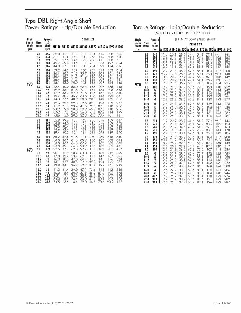
© Rexnord Industries, LLC, 2001, 2007. (161-110) 103
Type DBL Right Angle ShaftPower Ratings – Hp/Double Reduction Torque Ratings – lb-in/Double Reduction
(MULTIPLY VALUES LISTED BY 1000)
HighSpeedShaftrpm
NomRatio
ApproxLS
Shaftrpm
DRIVE SIZE
M1130 M1140 M1150 M1160 M1170 M1180 M1190 M1200
970
2.8 346 62.0 107 150 181 284 416 508 7653.2 303 61.1 101 150 180 273 416 508 7503.6 269 55.1 97.5 148 172 258 411 508 7114.0 243 49.7 69.6 117 181 285 338 497 6544.5 216 44.0 67.1 113 180 284 329 474 636
5.0 194 39.2 64.2 109 160 257 313 353 6145.6 173 26.4 48.3 71.3 95.7 138 209 261 3956.3 154 26.4 48.3 71.3 91.6 136 209 261 3737.1 137 26.4 43.6 71.3 104 138 209 261 4818.0 121 25.1 42.0 70.0 103 138 209 224 465
9.0 108 22.4 40.0 65.0 92.5 138 209 236 44510.0 97 19.9 36.1 57.6 77.1 131 163 208 38311.2 87 17.9 33.7 52.0 71.8 117 157 197 35012.5 78 15.7 30.4 45.2 63.8 103 148 195 33114.0 69 14.3 27.5 40.9 58.8 90.3 140 179 313
16.0 61 12.6 23.9 32.3 52.5 82.1 128 159 27718.0 54 11.2 21.1 33.4 41.6 72.1 89.8 118 21620.0 49 9.82 19.0 28.8 39.9 65.7 89.8 118 21622.4 43 8.92 17.2 26.0 36.8 57.8 89.2 114 19925.0 39 7.86 15.0 20.5 32.3 52.2 78.7 101 181
870
2.8 311 55.9 99.6 135 163 255 376 459 6873.2 272 54.8 94.0 135 161 245 376 459 6733.6 242 49.5 90.4 133 154 232 368 459 6384.0 218 44.6 62.4 105 163 262 303 459 5864.5 193 39.4 60.2 101 161 254 295 439 570
5.0 174 35.2 57.6 97.8 144 230 280 316 5505.6 155 23.8 43.5 64.3 85.9 125 189 235 3546.3 138 23.8 43.5 64.3 82.2 122 189 235 3357.1 123 23.8 39.1 64.3 93.9 125 189 235 4318.0 109 22.6 37.7 62.8 92.7 125 189 201 417
9.0 97 20.1 35.9 58.4 83.0 125 189 212 39910.0 87 17.8 32.4 53.4 69.1 117 147 187 35511.2 78 16.0 30.2 47.0 64.4 105 141 176 32412.5 70 14.1 27.3 40.6 57.2 92.6 133 175 30714.0 62 12.8 24.7 36.7 52.7 81.8 125 161 283
16.0 54 11.3 21.4 29.0 47.1 73.6 115 142 25618.0 48 10.0 18.9 30.0 37.9 65.7 81.2 107 19520.0 43.5 8.81 17.1 25.9 35.8 58.9 81.2 107 19522.4 38.8 8.00 15.5 23.4 33.0 51.9 80.1 102 17825.0 34.8 7.05 13.5 18.4 29.0 46.8 70.6 90.2 162
HighSpeedShaftrpm
NomRatio
ApproxLS
Shaftrpm
(LB-IN AT LOW SPEED SHAFT)
DRIVE SIZE
M1130 M1140 M1150 M1160 M1170 M1180 M1190 M1200
970
2.8 346 11.6 20.2 28.5 34.4 54.2 77.1 94.4 1443.2 303 12.9 21.0 31.8 38.1 57.2 88.4 105 1533.6 269 12.9 23.2 34.6 40.2 61.5 97.5 120 1634.0 243 12.9 18.3 31.0 47.7 76.2 88.8 130 1704.5 216 12.9 19.6 33.4 52.6 85.1 95.0 137 185
5.0 194 12.9 21.3 36.2 52.6 85.1 104 117 2005.6 173 9.77 17.6 26.6 35.1 50.1 78.1 94.4 1406.3 154 10.8 20.2 29.2 37.2 56.3 87.3 108 1497.1 137 12.0 20.2 33.1 47.4 64.1 96.7 120 2178.0 121 12.9 21.6 36.2 52.3 71.8 106 114 235
9.0 108 12.9 23.3 37.9 52.6 79.3 123 138 25210.0 97 12.9 23.5 37.0 50.0 85.1 107 134 24211.2 87 12.9 25.2 37.8 52.6 85.1 114 146 24912.5 78 12.9 25.2 37.6 52.6 85.1 122 163 26414.0 69 12.9 25.2 38.0 52.6 84.1 130 163 278
16.0 61 12.6 24.9 33.3 52.6 85.1 129 163 27518.0 54 12.9 25.2 38.3 48.7 82.5 103 137 24520.0 49 12.9 25.2 37.8 52.6 85.1 117 151 27522.4 43 12.9 25.2 38.1 52.6 84.5 131 163 28225.0 39 12.6 25.0 33.3 51.7 85.1 126 163 287
870
2.8 311 11.7 20.9 28.7 34.6 54.2 77.6 95.0 1443.2 272 12.9 21.7 32.0 38.1 57.2 88.9 105 1533.6 242 12.9 23.9 34.6 40.2 61.5 97.5 121 1634.0 218 12.9 18.3 31.0 47.9 78.2 88.8 134 1704.5 193 12.9 19.6 33.4 52.6 85.1 95.0 142 185
5.0 174 12.9 21.3 36.2 52.6 85.1 104 117 2005.6 155 9.81 17.7 26.7 35.1 50.4 78.5 94.9 1406.3 138 10.9 20.3 29.4 37.2 56.3 87.8 109 1497.1 123 12.0 20.2 33.3 47.7 64.4 97.2 120 2178.0 109 12.9 21.6 36.2 52.3 72.2 107 114 235
9.0 97 12.9 23.3 38.0 52.6 79.7 123 138 25210.0 87 12.9 23.5 38.2 50.0 85.1 107 134 25011.2 78 12.9 25.2 38.1 52.6 85.1 114 146 25712.5 70 12.9 25.2 37.7 52.6 85.1 122 159 27214.0 62 12.9 25.2 38.0 52.6 84.2 130 163 280
16.0 54 12.6 24.9 33.3 52.6 85.1 130 163 28418.0 48 12.9 25.2 38.3 49.5 83.8 104 140 24620.0 43.5 12.9 25.2 37.8 52.6 85.1 118 153 27622.4 38.8 12.9 25.2 38.2 52.6 84.6 131 163 28225.0 34.8 12.6 25.0 33.3 51.7 85.1 126 163 287
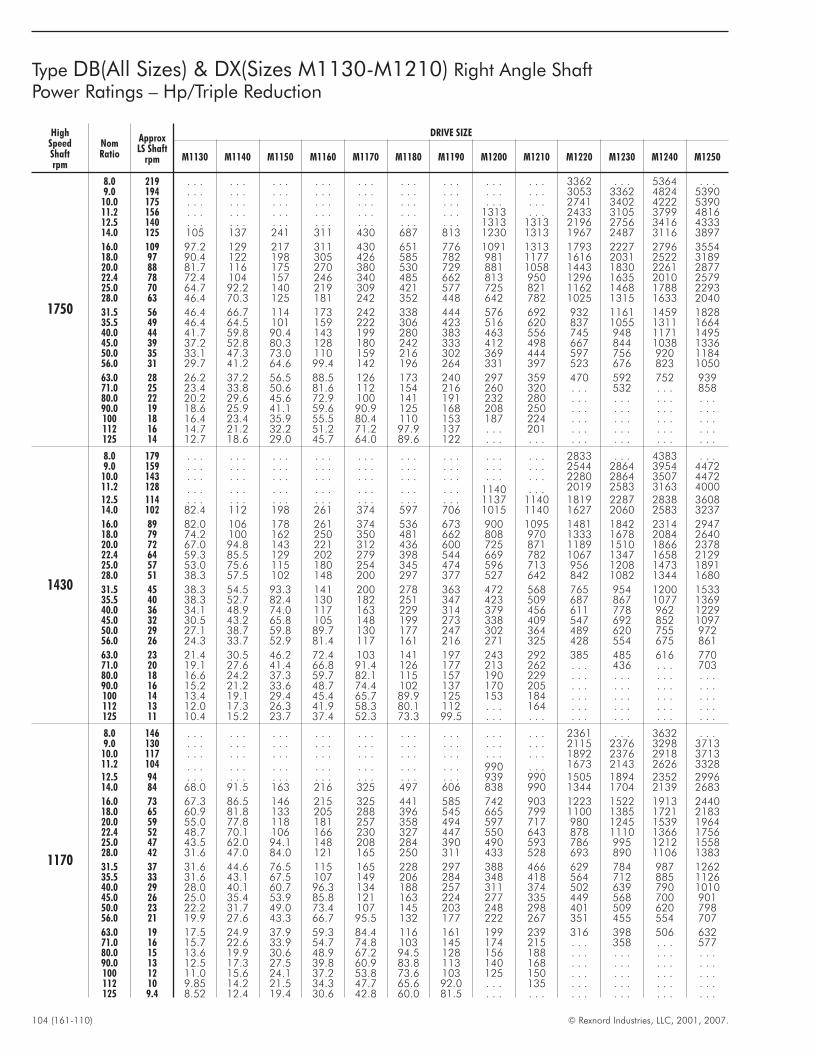
104 (161-110) © Rexnord Industries, LLC, 2001, 2007.
Type DB(All Sizes) & DX(Sizes M1130-M1210) Right Angle ShaftPower Ratings – Hp/Triple Reduction
HighSpeedShaftrpm
NomRatio
ApproxLS Shaft
rpm
DRIVE SIZE
M1130 M1140 M1150 M1160 M1170 M1180 M1190 M1200 M1210 M1220 M1230 M1240 M1250
1750
8.0 219 . . . . . . . . . . . . . . . . . . . . . . . . . . . 3362 . . . 5364 . . .9.0 194 . . . . . . . . . . . . . . . . . . . . . . . . . . . 3053 3362 4824 5390
10.0 175 . . . . . . . . . . . . . . . . . . . . . . . . . . . 2741 3402 4222 539011.2 156 . . . . . . . . . . . . . . . . . . . . . 1313 . . . 2433 3105 3799 481612.5 140 . . . . . . . . . . . . . . . . . . . . . 1313 1313 2196 2756 3416 433314.0 125 105 137 241 311 430 687 813 1230 1313 1967 2487 3116 3897
16.0 109 97.2 129 217 311 430 651 776 1091 1313 1793 2227 2796 355418.0 97 90.4 122 198 305 426 585 782 981 1177 1616 2031 2522 318920.0 88 81.7 116 175 270 380 530 729 881 1058 1443 1830 2261 287722.4 78 72.4 104 157 246 340 485 662 813 950 1296 1635 2010 257925.0 70 64.7 92.2 140 219 309 421 577 725 821 1162 1468 1788 229328.0 63 46.4 70.3 125 181 242 352 448 642 782 1025 1315 1633 2040
31.5 56 46.4 66.7 114 173 242 338 444 576 692 932 1161 1459 182835.5 49 46.4 64.5 101 159 222 306 423 516 620 837 1055 1311 166440.0 44 41.7 59.8 90.4 143 199 280 383 463 556 745 948 1171 149545.0 39 37.2 52.8 80.3 128 180 242 333 412 498 667 844 1038 133650.0 35 33.1 47.3 73.0 110 159 216 302 369 444 597 756 920 118456.0 31 29.7 41.2 64.6 99.4 142 196 264 331 397 523 676 823 1050
63.0 28 26.2 37.2 56.5 88.5 126 173 240 297 359 470 592 752 93971.0 25 23.4 33.8 50.6 81.6 112 154 216 260 320 . . . 532 . . . 85880.0 22 20.2 29.6 45.6 72.9 100 141 191 232 280 . . . . . . . . . . . .90.0 19 18.6 25.9 41.1 59.6 90.9 125 168 208 250 . . . . . . . . . . . .100 18 16.4 23.4 35.9 55.5 80.4 110 153 187 224 . . . . . . . . . . . .112 16 14.7 21.2 32.2 51.2 71.2 97.9 137 . . . 201 . . . . . . . . . . . .125 14 12.7 18.6 29.0 45.7 64.0 89.6 122 . . . . . . . . . . . . . . . . . .
1430
8.0 179 . . . . . . . . . . . . . . . . . . . . . . . . . . . 2833 . . . 4383 . . .9.0 159 . . . . . . . . . . . . . . . . . . . . . . . . . . . 2544 2864 3954 4472
10.0 143 . . . . . . . . . . . . . . . . . . . . . . . . . . . 2280 2864 3507 447211.2 128 . . . . . . . . . . . . . . . . . . . . . 1140 . . . 2019 2583 3163 400012.5 114 . . . . . . . . . . . . . . . . . . . . . 1137 1140 1819 2287 2838 360814.0 102 82.4 112 198 261 374 597 706 1015 1140 1627 2060 2583 3237
16.0 89 82.0 106 178 261 374 536 673 900 1095 1481 1842 2314 294718.0 79 74.2 100 162 250 350 481 662 808 970 1333 1678 2084 264020.0 72 67.0 94.8 143 221 312 436 600 725 871 1189 1510 1866 237822.4 64 59.3 85.5 129 202 279 398 544 669 782 1067 1347 1658 212925.0 57 53.0 75.6 115 180 254 345 474 596 713 956 1208 1473 189128.0 51 38.3 57.5 102 148 200 297 377 527 642 842 1082 1344 1680
31.5 45 38.3 54.5 93.3 141 200 278 363 472 568 765 954 1200 153335.5 40 38.3 52.7 82.4 130 182 251 347 423 509 687 867 1077 136940.0 36 34.1 48.9 74.0 117 163 229 314 379 456 611 778 962 122945.0 32 30.5 43.2 65.8 105 148 199 273 338 409 547 692 852 109750.0 29 27.1 38.7 59.8 89.7 130 177 247 302 364 489 620 755 97256.0 26 24.3 33.7 52.9 81.4 117 161 216 271 325 428 554 675 861
63.0 23 21.4 30.5 46.2 72.4 103 141 197 243 292 385 485 616 77071.0 20 19.1 27.6 41.4 66.8 91.4 126 177 213 262 . . . 436 . . . 70380.0 18 16.6 24.2 37.3 59.7 82.1 115 157 190 229 . . . . . . . . . . . .90.0 16 15.2 21.2 33.6 48.7 74.4 102 137 170 205 . . . . . . . . . . . .100 14 13.4 19.1 29.4 45.4 65.7 89.9 125 153 184 . . . . . . . . . . . .112 13 12.0 17.3 26.3 41.9 58.3 80.1 112 . . . 164 . . . . . . . . . . . .125 11 10.4 15.2 23.7 37.4 52.3 73.3 99.5 . . . . . . . . . . . . . . . . . .
1170
8.0 146 . . . . . . . . . . . . . . . . . . . . . . . . . . . 2361 . . . 3632 . . .9.0 130 . . . . . . . . . . . . . . . . . . . . . . . . . . . 2115 2376 3298 3713
10.0 117 . . . . . . . . . . . . . . . . . . . . . . . . . . . 1892 2376 2918 371311.2 104 . . . . . . . . . . . . . . . . . . . . . 990 . . . 1673 2143 2626 332812.5 94 . . . . . . . . . . . . . . . . . . . . . 939 990 1505 1894 2352 299614.0 84 68.0 91.5 163 216 325 497 606 838 990 1344 1704 2139 2683
16.0 73 67.3 86.5 146 215 325 441 585 742 903 1223 1522 1913 244018.0 65 60.9 81.8 133 205 288 396 545 665 799 1100 1385 1721 218320.0 59 55.0 77.8 118 181 257 358 494 597 717 980 1245 1539 196422.4 52 48.7 70.1 106 166 230 327 447 550 643 878 1110 1366 175625.0 47 43.5 62.0 94.1 148 208 284 390 490 593 786 995 1212 155828.0 42 31.6 47.0 84.0 121 165 250 311 433 528 693 890 1106 1383
31.5 37 31.6 44.6 76.5 115 165 228 297 388 466 629 784 987 126235.5 33 31.6 43.1 67.5 107 149 206 284 348 418 564 712 885 112640.0 29 28.0 40.1 60.7 96.3 134 188 257 311 374 502 639 790 101045.0 26 25.0 35.4 53.9 85.8 121 163 224 277 335 449 568 700 90150.0 23 22.2 31.7 49.0 73.4 107 145 203 248 298 401 509 620 79856.0 21 19.9 27.6 43.3 66.7 95.5 132 177 222 267 351 455 554 707
63.0 19 17.5 24.9 37.9 59.3 84.4 116 161 199 239 316 398 506 63271.0 16 15.7 22.6 33.9 54.7 74.8 103 145 174 215 . . . 358 . . . 57780.0 15 13.6 19.9 30.6 48.9 67.2 94.5 128 156 188 . . . . . . . . . . . .90.0 13 12.5 17.3 27.5 39.8 60.9 83.8 113 140 168 . . . . . . . . . . . .100 12 11.0 15.6 24.1 37.2 53.8 73.6 103 125 150 . . . . . . . . . . . .112 10 9.85 14.2 21.5 34.3 47.7 65.6 92.0 . . . 135 . . . . . . . . . . . .125 9.4 8.52 12.4 19.4 30.6 42.8 60.0 81.5 . . . . . . . . . . . . . . . . . .
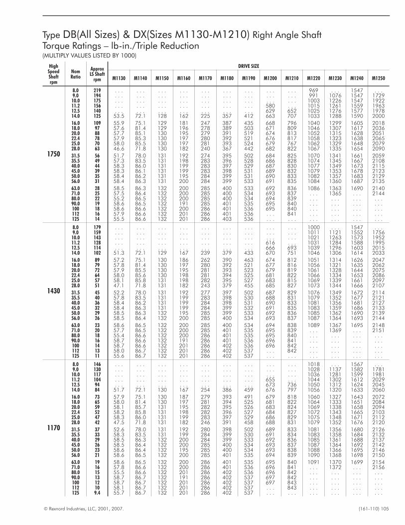
© Rexnord Industries, LLC, 2001, 2007. (161-110) 105
Type DB(All Sizes) & DX(Sizes M1130-M1210) Right Angle ShaftTorque Ratings – lb-in./Triple Reduction(MULTIPLY VALUES LISTED BY 1000)
HighSpeedShaftrpm
NomRatio
ApproxLS Shaft
rpm
DRIVE SIZE
M1130 M1140 M1150 M1160 M1170 M1180 M1190 M1200 M1210 M1220 M1230 M1240 M1250
1750
8.0 219 . . . . . . . . . . . . . . . . . . . . . . . . . . . 969 . . . 1547 . . .9.0 194 . . . . . . . . . . . . . . . . . . . . . . . . . . . 991 1076 1547 1729
10.0 175 . . . . . . . . . . . . . . . . . . . . . . . . . . . 1003 1226 1547 192211.2 156 . . . . . . . . . . . . . . . . . . . . . 580 . . . 1015 1261 1559 196312.5 140 . . . . . . . . . . . . . . . . . . . . . 629 652 1025 1276 1577 197814.0 125 53.5 72.1 128 162 225 357 412 663 707 1033 1288 1590 2000
16.0 109 55.9 75.1 129 181 247 387 435 668 796 1040 1299 1605 201818.0 97 57.6 81.4 129 196 278 389 503 671 809 1046 1307 1617 203620.0 88 57.7 85.1 130 195 279 391 519 674 813 1052 1315 1628 205122.4 78 57.9 85.3 130 197 280 392 521 676 817 1058 1323 1638 206525.0 70 58.0 85.5 130 197 281 393 524 679 767 1062 1329 1648 207928.0 63 46.6 71.8 130 182 240 367 442 682 822 1067 1335 1654 2090
31.5 56 51.7 78.0 131 192 274 395 502 684 825 1070 1341 1661 205935.5 49 57.3 83.5 131 198 283 396 528 686 828 1074 1345 1667 210840.0 44 58.3 86.0 131 199 283 397 529 687 830 1077 1349 1673 211545.0 39 58.3 86.1 131 199 283 398 531 689 832 1079 1353 1678 212350.0 35 58.4 86.2 131 195 284 399 531 690 833 1082 1357 1683 212956.0 31 58.4 86.3 131 200 284 399 533 691 835 1084 1360 1687 2135
63.0 28 58.5 86.3 132 200 285 400 533 692 836 1086 1363 1690 214071.0 25 57.5 86.4 132 200 285 400 534 693 837 . . . 1365 . . . 214480.0 22 55.2 86.5 132 200 285 400 534 694 839 . . . . . . . . . . . .90.0 19 58.6 86.5 132 191 285 401 535 695 840 . . . . . . . . . . . .100 18 58.6 86.6 132 200 286 401 536 695 840 . . . . . . . . . . . .112 16 57.9 86.6 132 201 286 401 536 . . . 841 . . . . . . . . . . . .125 14 55.5 86.6 132 201 286 403 536 . . . . . . . . . . . . . . . . . .
1430
8.0 179 . . . . . . . . . . . . . . . . . . . . . . . . . . . 1000 . . . 1547 . . .9.0 159 . . . . . . . . . . . . . . . . . . . . . . . . . . . 1011 1121 1552 1756
10.0 143 . . . . . . . . . . . . . . . . . . . . . . . . . . . 1021 1263 1573 195211.2 128 . . . . . . . . . . . . . . . . . . . . . 616 . . . 1031 1284 1588 199512.5 114 . . . . . . . . . . . . . . . . . . . . . 666 693 1039 1296 1603 201514.0 102 51.3 72.1 129 167 239 379 433 670 751 1046 1306 1614 2033
16.0 89 57.2 75.1 130 186 262 390 463 674 812 1051 1314 1626 204718.0 79 57.8 81.4 130 197 280 392 521 677 816 1056 1321 1635 206220.0 72 57.9 85.5 130 195 281 393 523 679 819 1061 1328 1644 207522.4 64 58.0 85.6 130 198 281 394 525 681 822 1066 1334 1653 208625.0 57 58.1 85.8 131 198 282 395 527 683 815 1069 1339 1661 209728.0 51 47.1 71.8 131 182 243 379 455 685 827 1073 1344 1666 2107
31.5 45 52.2 78.0 131 192 277 397 502 687 829 1076 1349 1672 211435.5 40 57.8 83.5 131 199 283 398 530 688 831 1079 1352 1677 212140.0 36 58.4 86.2 131 199 284 398 531 690 833 1081 1356 1681 212745.0 32 58.4 86.3 131 199 284 399 532 691 835 1083 1359 1686 213350.0 29 58.5 86.3 132 195 285 399 533 692 836 1085 1362 1690 213956.0 26 58.5 86.4 132 200 285 400 534 693 837 1087 1364 1693 2144
63.0 23 58.6 86.5 132 200 285 400 534 694 838 1089 1367 1695 214871.0 20 57.7 86.5 132 200 285 401 535 695 839 . . . 1369 . . . 215180.0 18 55.4 86.6 132 200 286 401 535 695 840 . . . . . . . . . . . .90.0 16 58.7 86.6 132 191 286 401 536 696 841 . . . . . . . . . . . .100 14 58.7 86.6 132 201 286 402 536 696 842 . . . . . . . . . . . .112 13 58.0 86.7 132 201 286 402 537 . . . 842 . . . . . . . . . . . .125 11 55.6 86.7 132 201 286 402 537 . . . . . . . . . . . . . . . . . .
1170
8.0 146 . . . . . . . . . . . . . . . . . . . . . . . . . . . 1018 . . . 1567 . . .9.0 130 . . . . . . . . . . . . . . . . . . . . . . . . . . . 1028 1137 1582 1781
10.0 117 . . . . . . . . . . . . . . . . . . . . . . . . . . . 1036 1281 1599 198111.2 104 . . . . . . . . . . . . . . . . . . . . . 655 . . . 1044 1302 1612 202912.5 94 . . . . . . . . . . . . . . . . . . . . . 673 736 1050 1312 1624 204514.0 84 51.7 72.1 130 167 254 386 459 676 797 1056 1320 1633 2060
16.0 73 57.9 75.1 130 187 279 393 491 679 818 1060 1327 1643 207218.0 65 58.0 81.4 130 197 281 394 525 681 822 1064 1333 1651 208420.0 59 58.1 85.7 131 195 282 395 526 683 824 1069 1338 1658 209422.4 52 58.2 85.8 131 198 282 396 527 684 827 1072 1343 1665 210325.0 47 58.3 86.0 131 199 283 397 529 686 829 1075 1348 1671 211228.0 42 47.5 71.8 131 182 246 391 458 688 831 1079 1352 1676 2120
31.5 37 52.6 78.0 131 192 280 398 502 689 833 1081 1356 1680 212635.5 33 58.3 83.5 131 199 284 399 530 691 834 1083 1358 1684 213240.0 29 58.5 86.3 132 200 284 399 533 692 836 1085 1361 1688 213745.0 26 58.5 86.4 132 200 285 400 534 693 837 1087 1364 1692 214250.0 23 58.6 86.4 132 195 285 400 534 693 838 1088 1366 1695 214656.0 21 58.6 86.5 132 200 285 401 535 694 839 1090 1368 1698 2150
63.0 19 58.6 86.5 132 200 286 401 535 695 840 1091 1370 1699 215471.0 16 57.8 86.6 132 200 286 401 536 696 841 . . . 1372 . . . 215680.0 15 55.5 86.6 132 201 286 402 536 696 842 . . . . . . . . . . . .90.0 13 58.7 86.7 132 191 286 402 537 697 842 . . . . . . . . . . . .100 12 58.7 86.7 132 201 286 402 537 697 843 . . . . . . . . . . . .112 10 58.1 86.7 132 201 286 402 537 . . . 843 . . . . . . . . . . . .125 9.4 55.7 86.7 132 201 286 402 537 . . . . . . . . . . . . . . . . . .
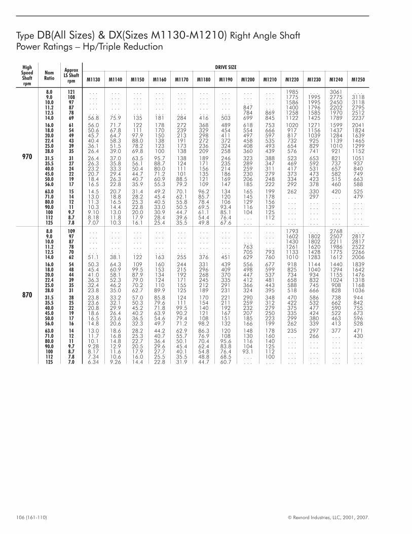
106 (161-110) © Rexnord Industries, LLC, 2001, 2007.
HighSpeedShaftrpm
NomRatio
ApproxLS Shaft
rpm
DRIVE SIZE
M1130 M1140 M1150 M1160 M1170 M1180 M1190 M1200 M1210 M1220 M1230 M1240 M1250
970
8.0 121 . . . . . . . . . . . . . . . . . . . . . . . . . . . 1985 . . . 3061 . . .9.0 108 . . . . . . . . . . . . . . . . . . . . . . . . . . . 1775 1995 2775 3118
10.0 97 . . . . . . . . . . . . . . . . . . . . . . . . . . . 1586 1995 2450 311811.2 87 . . . . . . . . . . . . . . . . . . . . . 847 . . . 1400 1796 2202 279512.5 78 . . . . . . . . . . . . . . . . . . . . . 784 869 1258 1585 1970 251214.0 69 56.8 75.9 135 181 284 416 503 699 845 1122 1425 1789 2237
16.0 61 56.0 71.7 122 178 272 368 489 618 753 1020 1271 1599 204118.0 54 50.6 67.8 111 170 239 329 454 554 666 917 1156 1437 182420.0 49 45.7 64.7 97.9 150 213 298 411 497 597 817 1039 1284 163922.4 43 40.4 58.3 88.0 138 191 272 372 458 535 732 925 1139 146525.0 39 36.1 51.5 78.2 123 173 236 324 408 493 654 829 1010 129928.0 35 26.4 39.0 69.8 100 138 209 258 360 439 576 741 921 1152
31.5 31 26.4 37.0 63.5 95.7 138 189 246 323 388 523 653 821 105135.5 27 26.3 35.8 56.1 88.7 124 171 235 289 347 469 592 737 93740.0 24 23.2 33.3 50.4 80.0 111 156 214 259 311 417 531 657 84045.0 22 20.7 29.4 44.7 71.2 101 135 186 230 279 373 473 582 74950.0 19 18.4 26.3 40.7 60.9 88.5 121 169 206 248 334 423 515 66356.0 17 16.5 22.8 35.9 55.3 79.2 109 147 185 222 292 378 460 588
63.0 15 14.5 20.7 31.4 49.2 70.1 96.2 134 165 199 262 330 420 52571.0 14 13.0 18.8 28.2 45.4 62.1 85.7 120 145 178 . . . 297 . . . 47980.0 12 11.3 16.5 25.3 40.5 55.8 78.4 106 129 156 . . . . . . . . . . . .90.0 11 10.3 14.4 22.8 33.0 50.5 69.5 93.4 116 139 . . . . . . . . . . . .100 9.7 9.10 13.0 20.0 30.9 44.7 61.1 85.1 104 125 . . . . . . . . . . . .112 8.7 8.18 11.8 17.9 28.4 39.6 54.4 76.4 . . . 112 . . . . . . . . . . . .125 7.8 7.07 10.3 16.1 25.4 35.5 49.8 67.6 . . . . . . . . . . . . . . . . . .
870
8.0 109 . . . . . . . . . . . . . . . . . . . . . . . . . . . 1793 . . . 2768 . . .9.0 97 . . . . . . . . . . . . . . . . . . . . . . . . . . . 1602 1802 2507 2817
10.0 87 . . . . . . . . . . . . . . . . . . . . . . . . . . . 1430 1802 2211 281711.2 78 . . . . . . . . . . . . . . . . . . . . . 763 . . . 1261 1620 1986 252212.5 70 . . . . . . . . . . . . . . . . . . . . . 705 793 1133 1428 1775 226614.0 62 51.1 38.1 122 163 255 376 451 629 760 1010 1283 1612 2006
16.0 54 50.3 64.3 109 160 244 331 439 556 677 918 1144 1440 183918.0 48 45.4 60.9 99.5 153 215 296 409 498 599 825 1040 1294 164220.0 44 41.0 58.1 87.9 134 192 268 370 447 537 734 934 1155 147622.4 39 36.3 52.3 79.0 124 171 245 335 412 481 658 832 1024 131825.0 35 32.4 46.2 70.2 110 155 212 291 366 443 588 745 908 116828.0 31 23.8 35.0 62.7 89.9 125 189 231 324 395 518 666 828 1036
31.5 28 23.8 33.2 57.0 85.8 124 170 221 290 348 470 586 738 94435.5 25 23.6 32.1 50.3 79.6 111 154 211 259 312 422 532 662 84240.0 22 20.8 29.9 45.2 71.8 99.5 140 192 232 279 375 477 590 75545.0 19 18.6 26.4 40.2 63.9 90.2 121 167 207 250 335 424 522 67350.0 17 16.5 23.6 36.5 54.6 79.4 108 151 185 223 299 380 463 59656.0 16 14.8 20.6 32.3 49.7 71.2 98.2 132 166 199 262 339 413 528
63.0 14 13.0 18.6 28.2 44.2 62.9 86.3 120 148 178 235 297 377 47171.0 12 11.7 16.8 25.3 40.7 55.7 76.9 108 130 160 . . . 266 . . . 43080.0 11 10.1 14.8 22.7 36.4 50.1 70.4 95.6 116 140 . . . . . . . . . . . .90.0 9.7 9.28 12.9 20.5 29.6 45.4 62.4 83.8 104 125 . . . . . . . . . . . .100 8.7 8.17 11.6 17.9 27.7 40.1 54.8 76.4 93.1 112 . . . . . . . . . . . .112 7.8 7.34 10.6 16.0 25.5 35.5 48.8 68.5 . . . 100 . . . . . . . . . . . .125 7.0 6.34 9.26 14.4 22.8 31.9 44.7 60.7 . . . . . . . . . . . . . . . . . .
Type DB(All Sizes) & DX(Sizes M1130-M1210) Right Angle ShaftPower Ratings – Hp/Triple Reduction
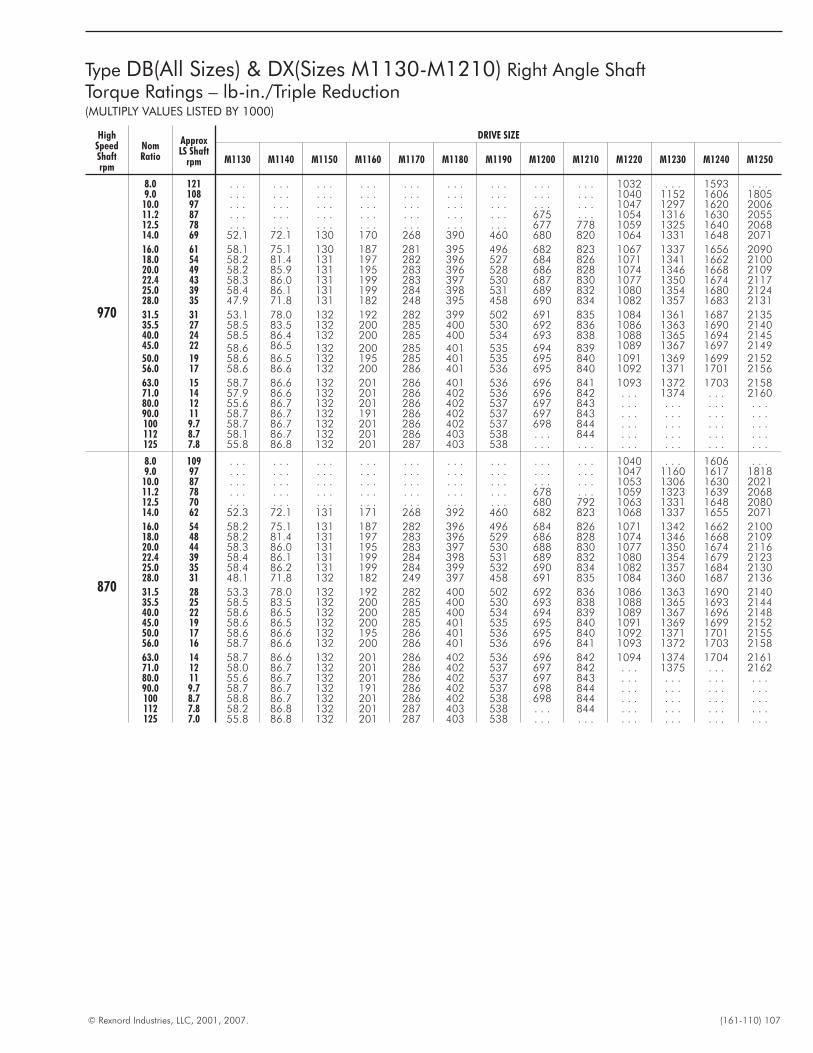
© Rexnord Industries, LLC, 2001, 2007. (161-110) 107
Type DB(All Sizes) & DX(Sizes M1130-M1210) Right Angle ShaftTorque Ratings – lb-in./Triple Reduction(MULTIPLY VALUES LISTED BY 1000)
HighSpeedShaftrpm
NomRatio
ApproxLS Shaft
rpm
DRIVE SIZE
M1130 M1140 M1150 M1160 M1170 M1180 M1190 M1200 M1210 M1220 M1230 M1240 M1250
970
8.0 121 . . . . . . . . . . . . . . . . . . . . . . . . . . . 1032 . . . 1593 . . .9.0 108 . . . . . . . . . . . . . . . . . . . . . . . . . . . 1040 1152 1606 1805
10.0 97 . . . . . . . . . . . . . . . . . . . . . . . . . . . 1047 1297 1620 200611.2 87 . . . . . . . . . . . . . . . . . . . . . 675 . . . 1054 1316 1630 205512.5 78 . . . . . . . . . . . . . . . . . . . . . 677 778 1059 1325 1640 206814.0 69 52.1 72.1 130 170 268 390 460 680 820 1064 1331 1648 2071
16.0 61 58.1 75.1 130 187 281 395 496 682 823 1067 1337 1656 209018.0 54 58.2 81.4 131 197 282 396 527 684 826 1071 1341 1662 210020.0 49 58.2 85.9 131 195 283 396 528 686 828 1074 1346 1668 210922.4 43 58.3 86.0 131 199 283 397 530 687 830 1077 1350 1674 211725.0 39 58.4 86.1 131 199 284 398 531 689 832 1080 1354 1680 212428.0 35 47.9 71.8 131 182 248 395 458 690 834 1082 1357 1683 2131
31.5 31 53.1 78.0 132 192 282 399 502 691 835 1084 1361 1687 213535.5 27 58.5 83.5 132 200 285 400 530 692 836 1086 1363 1690 214040.0 24 58.5 86.4 132 200 285 400 534 693 838 1088 1365 1694 214545.0 22 58.6 86.5 132 200 285 401 535 694 839 1089 1367 1697 214950.0 19 58.6 86.5 132 195 285 401 535 695 840 1091 1369 1699 215256.0 17 58.6 86.6 132 200 286 401 536 695 840 1092 1371 1701 2156
63.0 15 58.7 86.6 132 201 286 401 536 696 841 1093 1372 1703 215871.0 14 57.9 86.6 132 201 286 402 536 696 842 . . . 1374 . . . 216080.0 12 55.6 86.7 132 201 286 402 537 697 843 . . . . . . . . . . . .90.0 11 58.7 86.7 132 191 286 402 537 697 843 . . . . . . . . . . . .100 9.7 58.7 86.7 132 201 286 402 537 698 844 . . . . . . . . . . . .112 8.7 58.1 86.7 132 201 286 403 538 . . . 844 . . . . . . . . . . . .125 7.8 55.8 86.8 132 201 287 403 538 . . . . . . . . . . . . . . . . . .
870
8.0 109 . . . . . . . . . . . . . . . . . . . . . . . . . . . 1040 . . . 1606 . . .9.0 97 . . . . . . . . . . . . . . . . . . . . . . . . . . . 1047 1160 1617 1818
10.0 87 . . . . . . . . . . . . . . . . . . . . . . . . . . . 1053 1306 1630 202111.2 78 . . . . . . . . . . . . . . . . . . . . . 678 . . . 1059 1323 1639 206812.5 70 . . . . . . . . . . . . . . . . . . . . . 680 792 1063 1331 1648 208014.0 62 52.3 72.1 131 171 268 392 460 682 823 1068 1337 1655 2071
16.0 54 58.2 75.1 131 187 282 396 496 684 826 1071 1342 1662 210018.0 48 58.2 81.4 131 197 283 396 529 686 828 1074 1346 1668 210920.0 44 58.3 86.0 131 195 283 397 530 688 830 1077 1350 1674 211622.4 39 58.4 86.1 131 199 284 398 531 689 832 1080 1354 1679 212325.0 35 58.4 86.2 131 199 284 399 532 690 834 1082 1357 1684 213028.0 31 48.1 71.8 132 182 249 397 458 691 835 1084 1360 1687 2136
31.5 28 53.3 78.0 132 192 282 400 502 692 836 1086 1363 1690 214035.5 25 58.5 83.5 132 200 285 400 530 693 838 1088 1365 1693 214440.0 22 58.6 86.5 132 200 285 400 534 694 839 1089 1367 1696 214845.0 19 58.6 86.5 132 200 285 401 535 695 840 1091 1369 1699 215250.0 17 58.6 86.6 132 195 286 401 536 695 840 1092 1371 1701 215556.0 16 58.7 86.6 132 200 286 401 536 696 841 1093 1372 1703 2158
63.0 14 58.7 86.6 132 201 286 402 536 696 842 1094 1374 1704 216171.0 12 58.0 86.7 132 201 286 402 537 697 842 . . . 1375 . . . 216280.0 11 55.6 86.7 132 201 286 402 537 697 843 . . . . . . . . . . . .90.0 9.7 58.7 86.7 132 191 286 402 537 698 844 . . . . . . . . . . . .100 8.7 58.8 86.7 132 201 286 402 538 698 844 . . . . . . . . . . . .112 7.8 58.2 86.8 132 201 287 403 538 . . . 844 . . . . . . . . . . . .125 7.0 55.8 86.8 132 201 287 403 538 . . . . . . . . . . . . . . . . . .
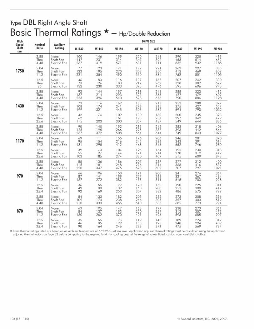
108 (161-110) © Rexnord Industries, LLC, 2001, 2007.
Type DBL Right Angle Shaft
Basic Thermal Ratings � – Hp/Double ReductionHigh
SpeedShaftrpm
NominalRatio
AuxiliaryCooling
DRIVE SIZE
M1130 M1140 M1150 M1160 M1170 M1180 M1190 M1200
1750
2.88 None 100 146 199 220 248 290 325 413Thru Shaft Fan 147 231 314 347 392 458 514 6524.48 Electric Fan 267 419 571 631 711 832 932 1185
5.04 None 77 123 171 192 221 262 297 385Thru Shaft Fan 122 195 270 302 350 413 469 60911.2 Electric Fan 221 354 490 550 634 752 851 1105
12.5 None 46 80 116 137 167 207 242 330Thru Shaft Fan 73 126 183 217 262 328 382 52225 Electric Fan 132 230 333 393 476 595 696 948
1430
2.88 None 92 144 197 218 246 288 323 412Thru Shaft Fan 137 214 293 323 365 427 479 6094.48 Electric Fan 253 396 540 598 676 790 886 1128
5.04 None 73 116 162 183 213 253 288 377Thru Shaft Fan 108 174 241 276 315 375 427 55711.2 Electric Fan 199 321 445 503 582 694 790 1032
12.5 None 42 74 109 130 160 200 235 323Thru Shaft Fan 62 111 161 193 237 297 349 47925.6 Electric Fan 115 203 300 357 437 549 644 886
1170
2.88 None 90 140 192 213 242 283 318 406Thru Shaft Fan 125 195 266 295 337 393 442 5644.48 Electric Fan 237 372 508 564 644 749 843 1077
5.04 None 69 111 155 176 206 246 281 370Thru Shaft Fan 95 154 216 245 286 343 391 51411.2 Electric Fan 181 295 412 468 546 652 746 980
12.5 None 39 70 104 125 154 195 230 318Thru Shaft Fan 55 97 144 174 214 270 319 44225.6 Electric Fan 102 185 274 330 409 515 609 843
970
2.88 None 85 136 186 207 237 277 312 400Thru Shaft Fan 115 181 248 276 314 368 416 5324.48 Electric Fan 220 347 475 528 602 707 797 1021
5.04 None 66 106 150 171 200 241 276 364Thru Shaft Fan 87 141 199 227 266 321 367 48411.2 Electric Fan 167 272 382 435 511 615 703 928
12.5 None 36 66 99 120 150 190 225 314Thru Shaft Fan 49 88 132 160 200 253 300 41725.4 Electric Fan 92 169 253 307 382 486 575 799
870
2.88 None 84 133 182 203 232 273 308 396Thru Shaft Fan 109 174 238 266 305 357 403 5194.48 Electric Fan 210 333 456 510 585 685 773 994
5.04 None 63 105 147 168 197 238 273 361Thru Shaft Fan 84 137 193 220 259 312 357 47311.2 Electric Fan 160 262 370 421 496 598 685 907
12.5 None 35 66 98 119 148 189 224 312Thru Shaft Fan 46 85 129 155 195 248 294 40925.4 Electric Fan 90 164 246 298 371 475 569 784
� Basic thermal ratings listed are based on an ambient temperature of 77°F(25°C) at sea level. Application adjusted thermal ratings must be calculated using the applicationadjusted thermal factors on Page 32 before comparing to the required load. For cooling beyond the range of values listed, contact your local district office.
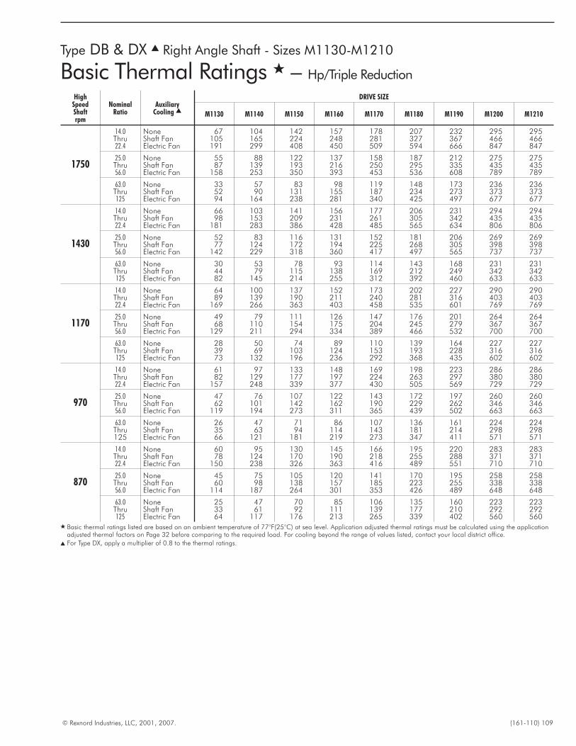
© Rexnord Industries, LLC, 2001, 2007. (161-110) 109
HighSpeedShaftrpm
NominalRatio
AuxiliaryCooling �
DRIVE SIZE
M1130 M1140 M1150 M1160 M1170 M1180 M1190 M1200 M1210
1750
14.0 None 67 104 142 157 178 207 232 295 295Thru Shaft Fan 105 165 224 248 281 327 367 466 46622.4 Electric Fan 191 299 408 450 509 594 666 847 847
25.0 None 55 88 122 137 158 187 212 275 275Thru Shaft Fan 87 139 193 216 250 295 335 435 43556.0 Electric Fan 158 253 350 393 453 536 608 789 789
63.0 None 33 57 83 98 119 148 173 236 236Thru Shaft Fan 52 90 131 155 187 234 273 373 373125 Electric Fan 94 164 238 281 340 425 497 677 677
1430
14.0 None 66 103 141 156 177 206 231 294 294Thru Shaft Fan 98 153 209 231 261 305 342 435 43522.4 Electric Fan 181 283 386 428 485 565 634 806 806
25.0 None 52 83 116 131 152 181 206 269 269Thru Shaft Fan 77 124 172 194 225 268 305 398 39856.0 Electric Fan 142 229 318 360 417 497 565 737 737
63.0 None 30 53 78 93 114 143 168 231 231Thru Shaft Fan 44 79 115 138 169 212 249 342 342125 Electric Fan 82 145 214 255 312 392 460 633 633
1170
14.0 None 64 100 137 152 173 202 227 290 290Thru Shaft Fan 89 139 190 211 240 281 316 403 40322.4 Electric Fan 169 266 363 403 458 535 601 769 769
25.0 None 49 79 111 126 147 176 201 264 264Thru Shaft Fan 68 110 154 175 204 245 279 367 36756.0 Electric Fan 129 211 294 334 389 466 532 700 700
63.0 None 28 50 74 89 110 139 164 227 227Thru Shaft Fan 39 69 103 124 153 193 228 316 316125 Electric Fan 73 132 196 236 292 368 435 602 602
970
14.0 None 61 97 133 148 169 198 223 286 286Thru Shaft Fan 82 129 177 197 224 263 297 380 38022.4 Electric Fan 157 248 339 377 430 505 569 729 729
25.0 None 47 76 107 122 143 172 197 260 260Thru Shaft Fan 62 101 142 162 190 229 262 346 34656.0 Electric Fan 119 194 273 311 365 439 502 663 663
63.0 None 26 47 71 86 107 136 161 224 224Thru Shaft Fan 35 63 94 114 143 181 214 298 298125 Electric Fan 66 121 181 219 273 347 411 571 571
870
14.0 None 60 95 130 145 166 195 220 283 283Thru Shaft Fan 78 124 170 190 218 255 288 371 37122.4 Electric Fan 150 238 326 363 416 489 551 710 710
25.0 None 45 75 105 120 141 170 195 258 258Thru Shaft Fan 60 98 138 157 185 223 255 338 33856.0 Electric Fan 114 187 264 301 353 426 489 648 648
63.0 None 25 47 70 85 106 135 160 223 223Thru Shaft Fan 33 61 92 111 139 177 210 292 292125 Electric Fan 64 117 176 213 265 339 402 560 560
� Basic thermal ratings listed are based on an ambient temperature of 77°F(25°C) at sea level. Application adjusted thermal ratings must be calculated using the applicationadjusted thermal factors on Page 32 before comparing to the required load. For cooling beyond the range of values listed, contact your local district office.
� For Type DX, apply a multiplier of 0.8 to the thermal ratings.
Type DB & DX � Right Angle Shaft - Sizes M1130-M1210
Basic Thermal Ratings � – Hp/Triple Reduction
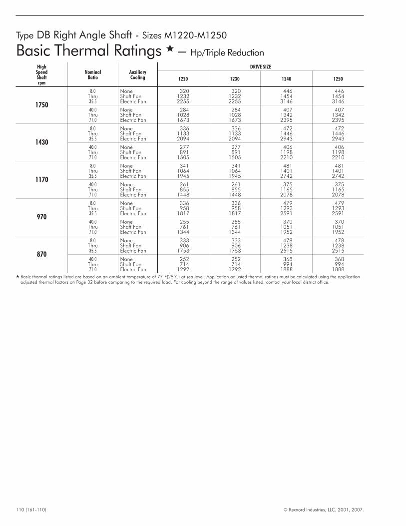
110 (161-110) © Rexnord Industries, LLC, 2001, 2007.
Type DB Right Angle Shaft - Sizes M1220-M1250
Basic Thermal Ratings � – Hp/Triple Reduction
HighSpeedShaftrpm
NominalRatio
AuxiliaryCooling
DRIVE SIZE
1220 1230 1240 1250
1750
8.0 None 320 320 446 446Thru Shaft Fan 1232 1232 1454 145435.5 Electric Fan 2255 2255 3146 3146
40.0 None 284 284 407 407Thru Shaft Fan 1028 1028 1342 134271.0 Electric Fan 1673 1673 2395 2395
1430
8.0 None 336 336 472 472Thru Shaft Fan 1133 1133 1446 144635.5 Electric Fan 2094 2094 2943 2943
40.0 None 277 277 406 406Thru Shaft Fan 891 891 1198 119871.0 Electric Fan 1505 1505 2210 2210
1170
8.0 None 341 341 481 481Thru Shaft Fan 1064 1064 1401 140135.5 Electric Fan 1945 1945 2742 2742
40.0 None 261 261 375 375Thru Shaft Fan 855 855 1165 116571.0 Electric Fan 1448 1448 2078 2078
970
8.0 None 336 336 479 479Thru Shaft Fan 958 958 1293 129335.5 Electric Fan 1817 1817 2591 2591
40.0 None 255 255 370 370Thru Shaft Fan 761 761 1051 105171.0 Electric Fan 1344 1344 1952 1952
870
8.0 None 333 333 478 478Thru Shaft Fan 906 906 1238 123835.5 Electric Fan 1753 1753 2515 2515
40.0 None 252 252 368 368Thru Shaft Fan 714 714 994 99471.0 Electric Fan 1292 1292 1888 1888
� Basic thermal ratings listed are based on an ambient temperature of 77°F(25°C) at sea level. Application adjusted thermal ratings must be calculated using the applicationadjusted thermal factors on Page 32 before comparing to the required load. For cooling beyond the range of values listed, contact your local district office.
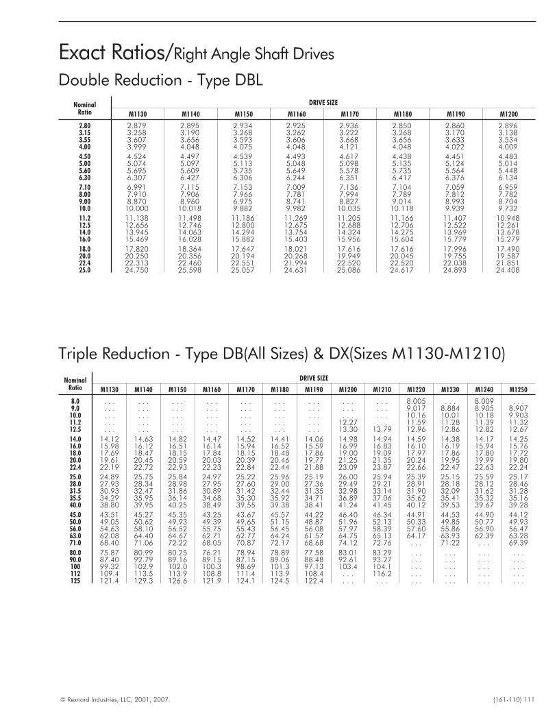
© Rexnord Industries, LLC, 2001, 2007. (161-110) 111
Triple Reduction - Type DB(All Sizes) & DX(Sizes M1130-M1210)
Exact Ratios/Right Angle Shaft Drives
NominalRatio
DRIVE SIZE
M1130 M1140 M1150 M1160 M1170 M1180 M1190 M1200 M1210 M1220 M1230 M1240 M1250
8.0 . . . . . . . . . . . . . . . . . . . . . . . . . . . 8.005 . . . 8.009 . . .9.0 . . . . . . . . . . . . . . . . . . . . . . . . . . . 9.017 8.884 8.905 8.907
10.0 . . . . . . . . . . . . . . . . . . . . . . . . . . . 10.16 10.01 10.18 9.90311.2 . . . . . . . . . . . . . . . . . . . . . 12.27 . . . 11.59 11.28 11.39 11.3212.5 . . . . . . . . . . . . . . . . . . . . . 13.30 13.79 12.96 12.86 12.82 12.67
14.0 14.12 14.63 14.82 14.47 14.52 14.41 14.06 14.98 14.94 14.59 14.38 14.17 14.2516.0 15.98 16.12 16.51 16.14 15.94 16.52 15.59 16.99 16.83 16.10 16.19 15.94 15.7618.0 17.69 18.47 18.15 17.84 18.15 18.48 17.86 19.00 19.09 17.97 17.86 17.80 17.7220.0 19.61 20.45 20.59 20.03 20.39 20.46 19.77 21.25 21.35 20.24 19.95 19.99 19.8022.4 22.19 22.72 22.93 22.23 22.84 22.44 21.88 23.09 23.87 22.66 22.47 22.63 22.24
25.0 24.89 25.75 25.84 24.97 25.22 25.96 25.19 26.00 25.94 25.39 25.15 25.59 25.1728.0 27.93 28.34 28.98 27.95 27.60 29.00 27.36 29.49 29.21 28.91 28.18 28.12 28.4631.5 30.93 32.47 31.86 30.89 31.42 32.44 31.35 32.98 33.14 31.90 32.09 31.62 31.2835.5 34.29 35.95 36.14 34.68 35.30 35.92 34.71 36.89 37.06 35.62 35.41 35.32 35.1640.0 38.80 39.95 40.25 38.49 39.55 39.38 38.41 41.24 41.45 40.12 39.53 39.67 39.28
45.0 43.51 45.27 45.35 43.25 43.67 45.57 44.22 46.40 46.34 44.91 44.53 44.90 44.1250.0 49.05 50.62 49.93 49.39 49.65 51.15 48.87 51.96 52.13 50.33 49.85 50.77 49.9356.0 54.63 58.10 56.52 55.75 55.43 56.45 56.08 57.97 58.39 57.60 55.86 56.90 56.4763.0 62.08 64.40 64.67 62.71 62.77 64.24 61.57 64.75 65.13 64.17 63.93 62.39 63.2871.0 68.40 71.06 72.22 68.05 70.87 72.17 68.68 74.12 72.76 . . . 71.22 . . . 69.39
80.0 75.87 80.99 80.25 76.21 78.94 78.89 77.58 83.01 83.29 . . . . . . . . . . . .90.0 87.40 92.79 89.16 89.15 87.15 89.06 88.48 92.61 93.27 . . . . . . . . . . . .100 99.32 102.9 102.0 100.3 98.69 101.3 97.13 103.4 104.1 . . . . . . . . . . . .112 109.4 113.5 113.9 108.8 111.4 113.9 108.4 . . . 116.2 . . . . . . . . . . . .125 121.4 129.3 126.6 121.9 124.1 124.5 122.4 . . . . . . . . . . . . . . . . . .
Double Reduction - Type DBL
NominalRatio
DRIVE SIZE
M1130 M1140 M1150 M1160 M1170 M1180 M1190 M1200
2.80 2.879 2.895 2.934 2.925 2.936 2.850 2.860 2.8963.15 3.258 3.190 3.268 3.262 3.222 3.268 3.170 3.1383.55 3.607 3.656 3.593 3.606 3.668 3.656 3.633 3.5344.00 3.999 4.048 4.075 4.048 4.121 4.048 4.022 4.009
4.50 4.524 4.497 4.539 4.493 4.617 4.438 4.451 4.4835.00 5.074 5.097 5.113 5.048 5.098 5.135 5.124 5.0145.60 5.695 5.609 5.735 5.649 5.578 5.735 5.564 5.4486.30 6.307 6.427 6.306 6.244 6.351 6.417 6.376 6.134
7.10 6.991 7.115 7.153 7.009 7.136 7.104 7.059 6.9598.00 7.910 7.906 7.966 7.781 7.994 7.789 7.812 7.7829.00 8.870 8.960 6.975 8.741 8.827 9.014 8.993 8.70410.0 10.000 10.018 9.882 9.982 10.035 10.118 9.939 9.732
11.2 11.138 11.498 11.186 11.269 11.205 11.166 11.407 10.94812.5 12.656 12.746 12.800 12.675 12.688 12.706 12.522 12.26114.0 13.945 14.063 14.294 13.754 14.324 14.275 13.969 13.67816.0 15.469 16.028 15.882 15.403 15.956 15.604 15.779 15.279
18.0 17.820 18.364 17.647 18.021 17.616 17.616 17.996 17.49020.0 20.250 20.356 20.194 20.268 19.949 20.045 19.755 19.58722.4 22.313 22.460 22.551 21.994 22.520 22.520 22.038 21.85125.0 24.750 25.598 25.057 24.631 25.086 24.617 24.893 24.408
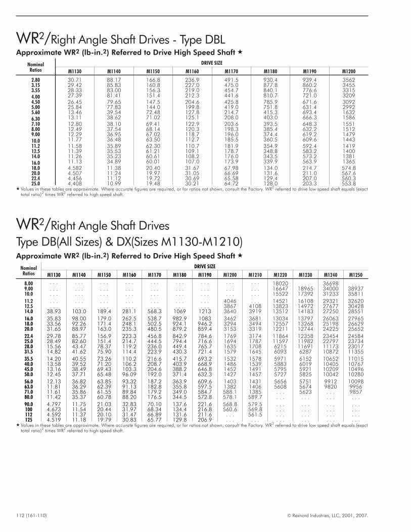
112 (161-110) © Rexnord Industries, LLC, 2001, 2007.
WR2/Right Angle Shaft Drives
Type DB(All Sizes) & DX(Sizes M1130-M1210)Approximate WR2 (lb-in.2) Referred to Drive High Speed Shaft �
NominalRatios
DRIVE SIZE
M1130 M1140 M1150 M1160 M1170 M1180 M1190 M1200 M1210 M1220 M1230 M1240 M1250
8.00 . . . . . . . . . . . . . . . . . . . . . . . . . . . 18020 . . . 36698 . . .9.00 . . . . . . . . . . . . . . . . . . . . . . . . . . . 16647 18965 34000 3893710.0 . . . . . . . . . . . . . . . . . . . . . . . . . . . 15522 17392 31233 35811
11.2 . . . . . . . . . . . . . . . . . . . . . 4046 . . . 14521 16108 29321 3262012.5 . . . . . . . . . . . . . . . . . . . . . 3867 4108 13823 14972 27677 3042814.0 38.93 103.0 189.4 281.1 568.3 1069 1213 3640 3919 13512 14183 27250 28551
16.0 35.83 98.00 179.0 262.5 538.7 982.9 1083 3462 3681 13034 13797 26063 2796518.0 33.56 92.26 171.4 248.1 502.5 924.1 946.2 3294 3494 12557 13268 25198 2662920.0 31.65 88.97 163.0 235.3 480.5 879.2 859.4 3153 3319 12211 12744 24225 25652
22.4 29.78 85.77 156.9 223.3 456.8 842.9 784.6 1769 3174 11864 12358 23454 2458425.0 28.49 82.60 151.4 214.7 444.5 794.4 716.6 1694 1787 11597 11982 22797 2373428.0 15.56 43.47 78.37 119.2 236.0 449.4 765.7 1635 1708 6215 11691 11173 2301731.5 14.82 41.62 75.90 114.4 223.9 430.3 721.4 1579 1645 6093 6287 10872 11355
35.5 14.20 40.55 73.26 110.2 216.6 415.7 693.2 1532 1578 5971 6152 10652 1101540.0 13.58 39.52 71.20 106.2 208.7 403.9 668.9 1486 1539 5883 6019 10405 1076745.0 13.16 38.49 69.43 103.3 204.6 388.2 646.8 1452 1491 5795 5921 10209 1049650.0 12.45 37.71 65.48 96.09 192.0 371.4 632.3 1427 1457 5727 5825 10042 10280
56.0 12.13 36.82 63.85 93.32 187.2 363.9 609.6 1403 1431 5656 5751 9912 1009863.0 11.81 36.29 62.39 91.13 182.8 355.8 597.5 1382 1406 5608 5674 9820 995671.0 11.61 35.86 61.55 89.84 179.2 349.0 584.7 588.1 1385 . . . 5623 . . . 985780.0 11.42 35.37 60.78 88.20 176.5 344.5 572.8 578.1 589.7 . . . . . . . . . . . .
90.0 4.797 11.75 21.03 32.83 70.10 137.6 221.6 568.8 579.5 . . . . . . . . . . . .100 4.673 11.54 20.44 31.97 68.34 134.4 216.8 560.6 569.8 . . . . . . . . . . . .112 4.592 11.37 20.10 31.47 66.89 131.6 211.6 . . . 561.5 . . . . . . . . . . . .125 4.519 11.18 19.79 30.83 65.77 129.8 206.9 . . . . . . . . . . . . . . . . . .
� Values in these tables are approximate. Where accurate figures are required, or for ratios not shown, consult the Factory. WR2 referred to drive low speed shaft equals (exacttotal ratio)2 times WR2 referred to high speed shaft.
WR2/Right Angle Shaft Drives - Type DBLApproximate WR2 (lb-in.2) Referred to Drive High Speed Shaft �
NominalRatios
DRIVE SIZE
M1130 M1140 M1150 M1160 M1170 M1180 M1190 M1200
2.80 30.71 88.17 166.8 236.9 491.5 930.4 939.4 35623.15 29.42 85.83 160.8 227.0 475.0 877.8 860.2 34553.55 28.33 83.00 156.3 219.0 454.7 840.1 776.6 33154.00 27.39 81.41 151.4 212.3 441.6 810.7 721.0 32094.50 26.45 79.65 147.5 204.6 425.8 785.9 671.6 30925.00 25.84 77.83 144.0 199.8 419.0 751.8 631.4 29925.60 13.46 39.54 72.48 127.8 214.7 415.3 693.4 16326.30 13.11 38.62 71.02 125.1 208.0 403.0 666.3 15867.10 12.80 38.10 69.41 122.9 203.6 393.5 648.3 15518.00 12.49 37.54 68.14 120.3 198.3 385.4 632.2 15129.00 12.29 36.95 67.02 118.7 196.0 374.4 619.2 147910.0 11.77 36.48 63.50 112.7 185.5 360.5 609.6 144311.2 11.58 35.89 62.30 110.7 181.9 354.9 592.4 141912.5 11.39 35.53 61.21 109.1 178.7 348.8 583.2 140014.0 11.26 35.23 60.61 108.2 176.0 343.5 573.2 138116.0 11.13 34.89 60.01 107.0 173.9 339.9 563.9 136518.0 4.582 11.38 20.40 31.67 67.98 134.0 214.7 574.820.0 4.507 11.24 19.97 31.05 66.69 131.6 211.0 567.622.4 4.456 11.12 19.72 30.69 65.58 129.4 207.0 560.325.0 4.408 10.99 19.48 30.21 64.72 128.0 203.3 553.8
� Values in these tables are approximate. Where accurate figures are required, or for ratios not shown, consult the Factory. WR2 referred to drive low speed shaft equals (exacttotal ratio)2 times WR2 referred to high speed shaft.

© Rexnord Industries, LLC, 2001, 2007. (161-110) 113
THIS PAGE INTENTIONALLY LEFT BLANK

114 (161-110) © Rexnord Industries, LLC, 2001, 2007.
Type DBL2 Double ReductionSizes M1130 – M1160/Dimensions — Inches
4-HOLESDD DIA. FORGRADE 5 BOLT
BOTHENDS
BB
AA
CC
EE
EE
CC
MM
L
8-HOLESU DIA. FORGRADE 5 BOLT
DO
W
E
V
FGB
GAG
K
F
J
AUSABLELENGTH
BUSABLELENGTH
NN
X
MM
SC
SD
TC
TDT
SE (TAPPED HOLE)SF (DEPTH)
TE (TAPPED HOLE)TF (DEPTH)
SA
SB
TB
TA
S
T
R
RA
DRIVESIZE � Ratios A AA B BB CC D DD E EE F G GA GB J K L M N � O Q R RA
M11302.80-16.0 3.94
9.84 2.64 3.43 3.15 15.83 0.94 16.69 1.18 4.41 7.87 3.94 7.87 3.54 26.14 11.42 4.92 9.7222.64
1.57 3.23 0.9818.0-25.0 2.76 21.46
M11402.80-16.0 4.33
12.44 2.64 3.07 3.54 17.56 1.10 18.58 1.18 4.57 9.06 4.72 9.06 3.94 29.61 13.39 5.91 10.7124.78
1.97 3.43 1.1818.0-25.0 3.54 23.94
M11502.80-16.0 5.91
12.99 3.54 3.94 3.94 19.69 1.10 20.87 1.18 4.76 10.63 5.91 9.96 4.96 33.66 14.57 6.50 12.2027.17
1.97 3.41 1.1818.0-25.0 3.94 25.35
M11602.80-16.0 5.91
14.57 3.54 3.74 3.94 21.26 1.10 22.05 1.18 4.92 11.71 6.50 10.93 5.41 36.61 15.94 6.99 12.8930.28
1.97 3.35 1.1818.0-25.0 5.51 29.88
DRIVESIZE � Ratios
Low Speed Shaft † High Speed Shaft †
U V W XApprox
WtlbS � SA SB SC SD SE SF T � TA TB TC TD TE TF
M11302.80-16.0
1.6535 k6 1.77 0.47 2.20 0.39 M16 1.421.5748 k6 1.69 0.47 3.54 0.39 M16 1.42
0.57 8.3538.46
6.10 69418.0-25.0 0.9843 j6 1.10 0.31 2.76 0.20 M10 0.87 37.28
M11402.80-16.0
2.1654 m6 2.32 0.63 2.20 0.39 M20 1.651.7717 k6 1.91 0.55 4.33
0.39M16 1.42
0.73 9.2942.32
7.09 99618.0-25.0 1.1811 j6 1.30 0.31 3.54 M10 0.87 41.50
M11502.80-16.0
2.7559 m6 2.93 0.79 3.15 0.39 M20 1.651.9685 k6 2.11 0.55 5.51 0.39 M16 1.42
0.73 10.4346.85
7.68 123518.0-25.0 1.3780 k6 1.50 0.39 3.94 0.20 M12 1.10 45.04
M11602.80-16.0
2.9528 m6 3.15 0.79 3.15 0.39 M20 1.652.1654 m6 2.32 0.63 5.71
0.39M20 1.65
0.94 11.0251.54
8.37 141818.0-25.0 1.5748 k6 1.69 0.47 5.31 M16 1.42 51.14
� Drawings are representative of this series of drives and do not agree in exact detail for all sizes. Gear drives are for horizontal floor mounted operation unless specificallystated otherwise. Consult the Factory for other mountings. Dimensions are for reference only and are subject to change without notice unless certified.
† Key Sizes per ISO/R773-1969, Form A. Tapped center hole to DIN 332, threads 6H.� j6 tolerance for shaft diameters 1.2” and less, k6 tolerance for shaft diameters over 1.2” to 2.0”, m6 tolerance for shaft diameters above 2.0”.� Single low speed shaft extension is standard; double extension is special.

© Rexnord Industries, LLC, 2001, 2007. (161-110) 115
Type DBL2 Double ReductionSizes M1170 – M1200/Dimensions — Inches
4-HOLESDD DIA. FORGRADE 5 BOLT
BOTHENDS
BB
AA
CC
EE
EE
CC
MM
L
8-HOLESU DIA. FORGRADE 5 BOLT
DO
W
E
V
FGB
GAG
K
F
J
AUSABLELENGTH
BUSABLELENGTH
NN
X
MM
SC
SD
TC
TDT
SE (TAPPED HOLE)SF (DEPTH)
TE (TAPPED HOLE)TF (DEPTH)
SA
SB
TB
TA
S
T
R
RA
DRIVESIZE � Ratios A AA B BB CC D DD E EE F G GA GB J K L M N � O Q R RA
M11702.80-16.0 6.10
16.93 4.53 3.94 3.94 23.23 1.38 24.80 1.18 5.51 13.78 5.91 12.60 5.12 40.94 16.14 7.09 13.9831.38
1.97 3.54 1.1818.0-25.0 5.91 31.14
M11802.80-16.0 7.09
18.50 4.33 3.94 3.94 26.38 1.38 26.38 1.18 5.51 16.14 7.09 14.17 6.69 46.06 18.50 8.27 15.1634.65
1.97 3.74 1.1818.0-25.0 6.30 33.86
M11902.80-16.0 7.68
21.26 5.91 4.13 4.33 29.33 1.65 29.53 1.18 5.91 18.31 7.09 17.13 6.30 51.97 20.08 8.46 17.4237.60 3.35
4.33 1.1818.0-25.0 6.89 36.81
M12002.80-16.0 9.45
25.20 7.28 5.12 5.91 34.84 1.65 35.43 1.57 6.30 21.46 7.87 22.05 6.50 60.83 22.44 9.65 19.8843.90
3.35 4.33 1.3818.0-25.0 9.45 43.90
DRIVESIZE � Ratios
Low Speed Shaft † High Speed Shaft †
U V W XApprox
WtlbS � SA SB SC SD SE SF T � TA TB TC TD TE TF
M11702.80-16.0
3.1496 m6 3.35 0.87 3.94 0.59 M20 1.652.1654 m6 2.32 0.63 6.30 0.39 M20 1.65
0.94 12.4054.61
8.46 188918.0-25.0 1.9685 k6 2.11 0.55 5.51 0.39 M16 1.42 54.37
M11802.80-16.0
3.7402 m6 3.94 0.98 3.94 0.59 M24 1.972.7559 m6 2.93 0.79 7.09
0.39 M20 1.65 1.10 13.1961.02
9.65 274018.0-25.0 2.1654 m6 2.32 0.63 6.30 60.24
M11902.80-16.0
3.9370 m6 4.17 1.10 4.92 0.59 M24 1.973.1496 m6 3.35 0.87 7.09 0.59
M20 1.65 1.38 14.7666.93
10.43 333318.0-25.0 2.5591 m6 2.72 0.71 6.30 0.39 66.14
M12002.80-16.0
5.5118 m6 5.83 14.2 6.30 0.79 M24 1.974.3307 m6 4.57 1.10
7.87 0.79M24 1.97
1.38 17.7278.74
11.61 508818.0-25.0 2.9528 m6 3.15 0.79 M20 1.65 78.74
� Drawings are representative of this series of drives and do not agree in exact detail for all sizes. Gear drives are for horizontal floor mounted operation unless specificallystated otherwise. Consult the Factory for other mountings. Dimensions are for reference only and are subject to change without notice unless certified.
† Key Sizes per ISO/R773-1969, Form A. Tapped center hole to DIN 332, threads 6H.� j6 tolerance for shaft diameters 1.2” and less, k6 tolerance for shaft diameters over 1.2” to 2.0”, m6 tolerance for shaft diameters above 2.0”.� Single low speed shaft extension is standard; double extension is special.
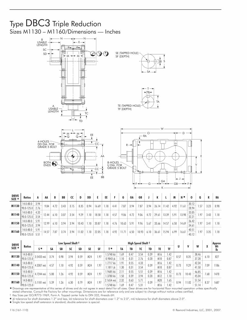
116 (161-110) © Rexnord Industries, LLC, 2001, 2007.
Type DBC3 Triple ReductionSizes M1130 – M1160/Dimensions — Inches
W
O D
V
E
F
8-HOLESU DIA. FORGRADE 5 BOLT
GGA
GB F
K
J
SA
SB S
SE (TAPPED HOLE)SF (DEPTH)
TE (TAPPED HOLE)TF (DEPTH)
TA
TB
T
TD
X
T
TC
AUSABLELENGTH
SD
SC
BUSABLELENGTH
N N
MM
AA
4-HOLESDD DIA. FORGRADE 5 BOLT
MMQ Q
L
BBEE
CC
EE
CC
BOTHENDS
R
RA
DRIVESIZE � Ratios A AA B BB CC D DD E EE F G GA GB J K L M N � O Q R RA
M113014.0-80.0 3.94
9.84 4.72 3.43 3.15 8.35 0.94 16.69 1.18 4.41 7.87 3.94 7.87 3.94 26.14 11.42 4.92 11.6130.12
1.57 3.23 0.9890.0-125.0 2.76 28.94
M114014.0-80.0 4.33
12.44 6.10 3.07 3.54 9.29 1.10 18.58 1.18 4.57 9.06 4.72 9.06 4.72 29.61 13.39 5.91 13.9833.05
1.97 3.43 1.1890.0-125.0 3.54 32.21
M115014.0-80.0 5.91
12.99 6.10 3.94 3.94 10.43 1.10 20.87 1.18 4.76 10.63 5.91 9.96 5.67 33.66 14.57 6.50 14.6936.42
1.97 3.41 1.1890.0-125.0 3.94 34.61
M116014.0-80.0 5.91
14.57 7.87 3.74 3.94 11.02 1.10 22.05 1.18 4.92 11.71 6.50 10.93 6.10 36.61 15.94 6.99 16.6140.51
1.97 3.35 1.1890.0-125.0 5.51 40.12
DRIVESIZE � Ratios
Low Speed Shaft † High Speed Shaft †
U V W XApprox
WtlbS � SA SB SC SD SE SF T � TA TB TC TD TE TF
M113014.0-80.0
3.5433 m6 3.74 0.98 3.94 0.59 M24 1.971.5748 k6 1.69 0.47 3.54 0.39 M16 1.42
0.57 8.3538.46
6.10 82790.0-125.0 0.9843 j6 1.10 0.31 2.76 0.20 M10 0.87 37.28
M114014.0-80.0
4.3307 m6 4.57 1.10 4.92 0.59 M24 1.971.7717 k6 1.91 0.55 4.33
0.39M16 1.42
0.73 9.2942.34
7.09 118690.0-125.0 1.1811 j6 1.30 0.31 3.54 M10 0.87 41.50
M115014.0-80.0
4.7244 m6 5.00 1.26 4.92 0.59 M24 1.971.9685 k6 2.11 0.55 5.51 0.39 M16 1.42
0.73 10.4346.85
7.68 147090.0-125.0 1.3780 k6 1.50 0.39 3.94 0.20 M12 1.10 45.04
M116014.0-80.0
5.1181 m6 5.39 1.26 6.30 0.79 M24 1.972.1654 m6 2.32 0.63 5.71
0.39M20 1.65
0.94 11.0251.54
8.37 168790.0-125.0 1.5748 k6 1.69 0.47 5.31 M16 1.42 51.14
� Drawings are representative of this series of drives and do not agree in exact detail for all sizes. Gear drives are for horizontal floor mounted operation unless specificallystated otherwise. Consult the Factory for other mountings. Dimensions are for reference only and are subject to change without notice unless certified.
† Key Sizes per ISO/R773-1969, Form A. Tapped center hole to DIN 332, threads 6H.� j6 tolerance for shaft diameters 1.2” and less, k6 tolerance for shaft diameters over 1.2” to 2.0”, m6 tolerance for shaft diameters above 2.0”.� Single low speed shaft extension is standard; double extension is special.
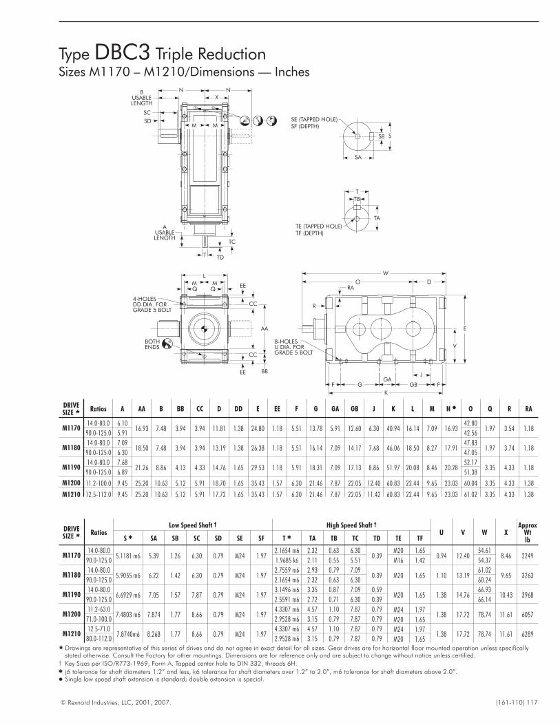
© Rexnord Industries, LLC, 2001, 2007. (161-110) 117
Type DBC3 Triple ReductionSizes M1170 – M1210/Dimensions — Inches
W
O D
V
E
F
8-HOLESU DIA. FORGRADE 5 BOLT
GGA
GB F
K
J
SA
SB S
SE (TAPPED HOLE)SF (DEPTH)
TE (TAPPED HOLE)TF (DEPTH)
TA
TB
T
TD
X
T
TC
AUSABLELENGTH
SD
SC
BUSABLELENGTH
N N
MM
AA
4-HOLESDD DIA. FORGRADE 5 BOLT
MMQ Q
L
BBEE
CC
EE
CC
BOTHENDS
R
RA
DRIVESIZE � Ratios A AA B BB CC D DD E EE F G GA GB J K L M N � O Q R RA
M117014.0-80.0 6.10
16.93 7.48 3.94 3.94 11.81 1.38 24.80 1.18 5.51 13.78 5.91 12.60 6.30 40.94 16.14 7.09 16.9342.80
1.97 3.54 1.1890.0-125.0 5.91 42.56
M118014.0-80.0 7.09
18.50 7.48 3.94 3.94 13.19 1.38 26.38 1.18 5.51 16.14 7.09 14.17 7.68 46.06 18.50 8.27 17.9147.83
1.97 3.74 1.1890.0-125.0 6.30 47.05
M119014.0-80.0 7.68
21.26 8.86 4.13 4.33 14.76 1.65 29.53 1.18 5.91 18.31 7.09 17.13 8.86 51.97 20.08 8.46 20.2852.17
3.35 4.33 1.1890.0-125.0 6.89 51.38
M1200 11.2-100.0 9.45 25.20 10.63 5.12 5.91 18.70 1.65 35.43 1.57 6.30 21.46 7.87 22.05 12.40 60.83 22.44 9.65 23.03 60.04 3.35 4.33 1.38
M1210 12.5-112.0 9.45 25.20 10.63 5.12 5.91 17.72 1.65 35.43 1.57 6.30 21.46 7.87 22.05 11.42 60.83 22.44 9.65 23.03 61.02 3.35 4.33 1.38
DRIVESIZE � Ratios
Low Speed Shaft † High Speed Shaft †
U V W XApprox
WtlbS � SA SB SC SD SE SF T � TA TB TC TD TE TF
M117014.0-80.0
5.1181 m6 5.39 1.26 6.30 0.79 M24 1.972.1654 m6 2.32 0.63 6.30
0.39M20 1.65
0.94 12.4054.61
8.46 224990.0-125.0 1.9685 k6 2.11 0.55 5.51 M16 1.42 54.37
M118014.0-80.0
5.9055 m6 6.22 1.42 6.30 0.79 M24 1.972.7559 m6 2.93 0.79 7.09
0.39 M20 1.65 1.10 13.1961.02
9.65 326390.0-125.0 2.1654 m6 2.32 0.63 6.30 60.24
M119014.0-80.0
6.6929 m6 7.05 1.57 7.87 0.79 M24 1.973.1496 m6 3.35 0.87 7.09 0.59
M20 1.65 1.38 14.7666.93
10.43 396890.0-125.0 2.5591 m6 2.72 0.71 6.30 0.39 66.14
M120011.2-63.0
7.4803 m6 7.874 1.77 8.66 0.79 M24 1.974.3307 m6 4.57 1.10 7.87 0.79 M24 1.97
1.38 17.72 78.74 11.61 605771.0-100.0 2.9528 m6 3.15 0.79 7.87 0.79 M20 1.65
M121012.5-71.0
7.8740m6 8.268 1.77 8.66 0.79 M24 1.974.3307 m6 4.57 1.10 7.87 0.79 M24 1.97
1.38 17.72 78.74 11.61 628980.0-112.0 2.9528 m6 3.15 0.79 7.87 0.79 M20 1.65
� Drawings are representative of this series of drives and do not agree in exact detail for all sizes. Gear drives are for horizontal floor mounted operation unless specificallystated otherwise. Consult the Factory for other mountings. Dimensions are for reference only and are subject to change without notice unless certified.
† Key Sizes per ISO/R773-1969, Form A. Tapped center hole to DIN 332, threads 6H.� j6 tolerance for shaft diameters 1.2” and less, k6 tolerance for shaft diameters over 1.2” to 2.0”, m6 tolerance for shaft diameters above 2.0”.� Single low speed shaft extension is standard; double extension is special.
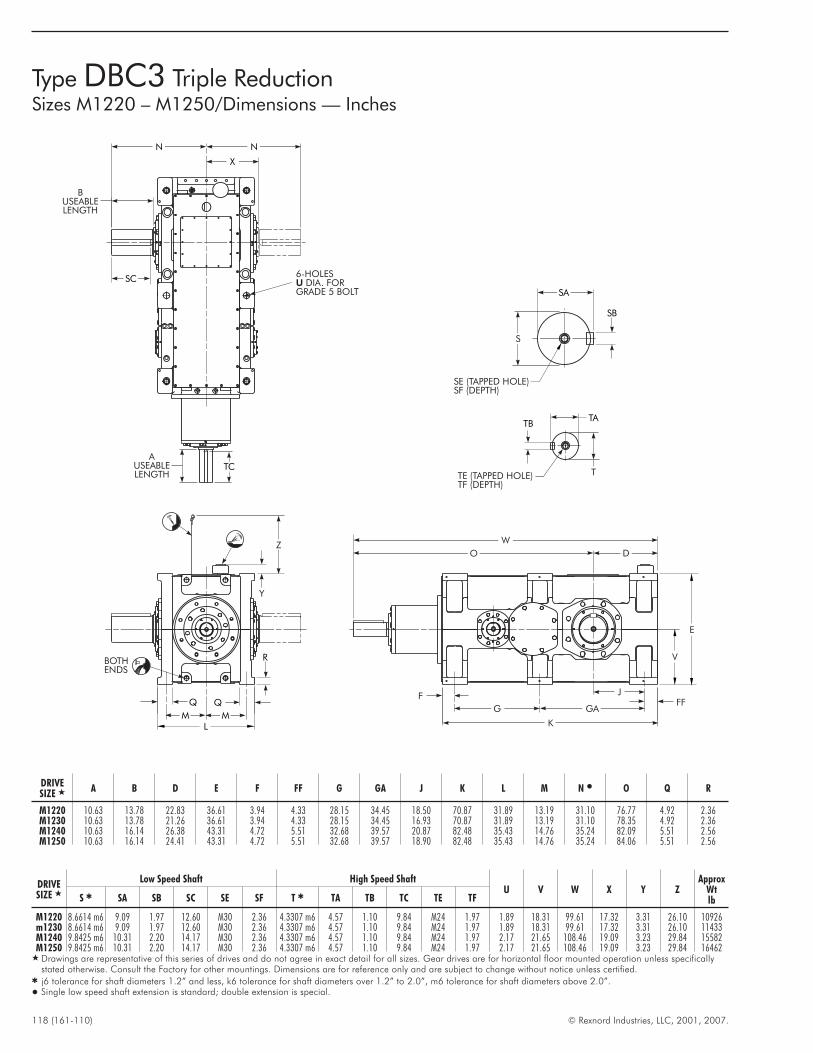
118 (161-110) © Rexnord Industries, LLC, 2001, 2007.
Type DBC3 Triple ReductionSizes M1220 – M1250/Dimensions — Inches
FFF
J
GA
K
G
V
E
D
W
R
Y
Z
BOTHENDS
MML
TATB
TTE (TAPPED HOLE)TF (DEPTH)
SB
SA
S
SE (TAPPED HOLE)SF (DEPTH)
O
AUSEABLELENGTH
N
X
N
BUSEABLELENGTH
SC6-HOLES
DIA. FORGRADE 5 BOLTU
TC
DRIVESIZE � A B D E F FF G GA J K L M N � O Q R
M1220 10.63 13.78 22.83 36.61 3.94 4.33 28.15 34.45 18.50 70.87 31.89 13.19 31.10 76.77 4.92 2.36M1230 10.63 13.78 21.26 36.61 3.94 4.33 28.15 34.45 16.93 70.87 31.89 13.19 31.10 78.35 4.92 2.36M1240 10.63 16.14 26.38 43.31 4.72 5.51 32.68 39.57 20.87 82.48 35.43 14.76 35.24 82.09 5.51 2.56M1250 10.63 16.14 24.41 43.31 4.72 5.51 32.68 39.57 18.90 82.48 35.43 14.76 35.24 84.06 5.51 2.56
DRIVESIZE �
Low Speed Shaft High Speed ShaftU V W X Y Z
ApproxWtlbS � SA SB SC SE SF T � TA TB TC TE TF
M1220 8.6614 m6 9.09 1.97 12.60 M30 2.36 4.3307 m6 4.57 1.10 9.84 M24 1.97 1.89 18.31 99.61 17.32 3.31 26.10 10926m1230 8.6614 m6 9.09 1.97 12.60 M30 2.36 4.3307 m6 4.57 1.10 9.84 M24 1.97 1.89 18.31 99.61 17.32 3.31 26.10 11433M1240 9.8425 m6 10.31 2.20 14.17 M30 2.36 4.3307 m6 4.57 1.10 9.84 M24 1.97 2.17 21.65 108.46 19.09 3.23 29.84 15582M1250 9.8425 m6 10.31 2.20 14.17 M30 2.36 4.3307 m6 4.57 1.10 9.84 M24 1.97 2.17 21.65 108.46 19.09 3.23 29.84 16462
� Drawings are representative of this series of drives and do not agree in exact detail for all sizes. Gear drives are for horizontal floor mounted operation unless specificallystated otherwise. Consult the Factory for other mountings. Dimensions are for reference only and are subject to change without notice unless certified.
� j6 tolerance for shaft diameters 1.2” and less, k6 tolerance for shaft diameters over 1.2” to 2.0”, m6 tolerance for shaft diameters above 2.0”.� Single low speed shaft extension is standard; double extension is special.

© Rexnord Industries, LLC, 2001, 2007. (161-110) 119
THIS PAGE INTENTIONALLY LEFT BLANK
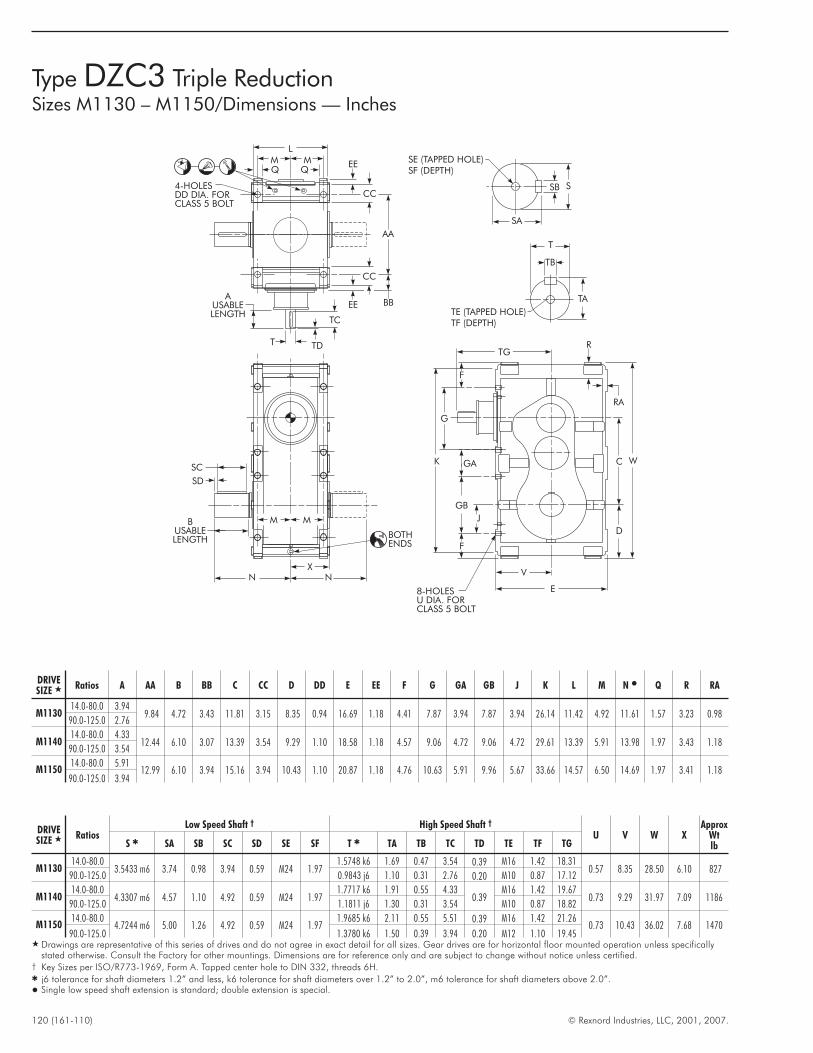
120 (161-110) © Rexnord Industries, LLC, 2001, 2007.
Type DZC3 Triple ReductionSizes M1130 – M1150/Dimensions — Inches
TE (TAPPED HOLE)TF (DEPTH)
TA
TB
T
SA
SB S
SE (TAPPED HOLE)SF (DEPTH)
W
D
V
E
F
8-HOLESU DIA. FORCLASS 5 BOLT
G
GA
GB
F
K
J
C
TGT
TC
TD
AUSABLELENGTH
AA
4-HOLESDD DIA. FORCLASS 5 BOLT
BBEE
CC
EE
CC
MMQ Q
L
X
MM
SD
SC
BUSABLELENGTH
N N
BOTHENDS
R
RA
DRIVESIZE � Ratios A AA B BB C CC D DD E EE F G GA GB J K L M N � Q R RA
M113014.0-80.0 3.94
9.84 4.72 3.43 11.81 3.15 8.35 0.94 16.69 1.18 4.41 7.87 3.94 7.87 3.94 26.14 11.42 4.92 11.61 1.57 3.23 0.9890.0-125.0 2.76
M114014.0-80.0 4.33
12.44 6.10 3.07 13.39 3.54 9.29 1.10 18.58 1.18 4.57 9.06 4.72 9.06 4.72 29.61 13.39 5.91 13.98 1.97 3.43 1.1890.0-125.0 3.54
M115014.0-80.0 5.91
12.99 6.10 3.94 15.16 3.94 10.43 1.10 20.87 1.18 4.76 10.63 5.91 9.96 5.67 33.66 14.57 6.50 14.69 1.97 3.41 1.1890.0-125.0 3.94
DRIVESIZE � Ratios
Low Speed Shaft † High Speed Shaft †
U V W XApprox
WtlbS � SA SB SC SD SE SF T � TA TB TC TD TE TF TG
M113014.0-80.0
3.5433 m6 3.74 0.98 3.94 0.59 M24 1.971.5748 k6 1.69 0.47 3.54 0.39 M16 1.42 18.31
0.57 8.35 28.50 6.10 82790.0-125.0 0.9843 j6 1.10 0.31 2.76 0.20 M10 0.87 17.12
M114014.0-80.0
4.3307 m6 4.57 1.10 4.92 0.59 M24 1.971.7717 k6 1.91 0.55 4.33
0.39M16 1.42 19.67
0.73 9.29 31.97 7.09 118690.0-125.0 1.1811 j6 1.30 0.31 3.54 M10 0.87 18.82
M115014.0-80.0
4.7244 m6 5.00 1.26 4.92 0.59 M24 1.971.9685 k6 2.11 0.55 5.51 0.39 M16 1.42 21.26
0.73 10.43 36.02 7.68 147090.0-125.0 1.3780 k6 1.50 0.39 3.94 0.20 M12 1.10 19.45
� Drawings are representative of this series of drives and do not agree in exact detail for all sizes. Gear drives are for horizontal floor mounted operation unless specificallystated otherwise. Consult the Factory for other mountings. Dimensions are for reference only and are subject to change without notice unless certified.
† Key Sizes per ISO/R773-1969, Form A. Tapped center hole to DIN 332, threads 6H.� j6 tolerance for shaft diameters 1.2” and less, k6 tolerance for shaft diameters over 1.2” to 2.0”, m6 tolerance for shaft diameters above 2.0”.� Single low speed shaft extension is standard; double extension is special.
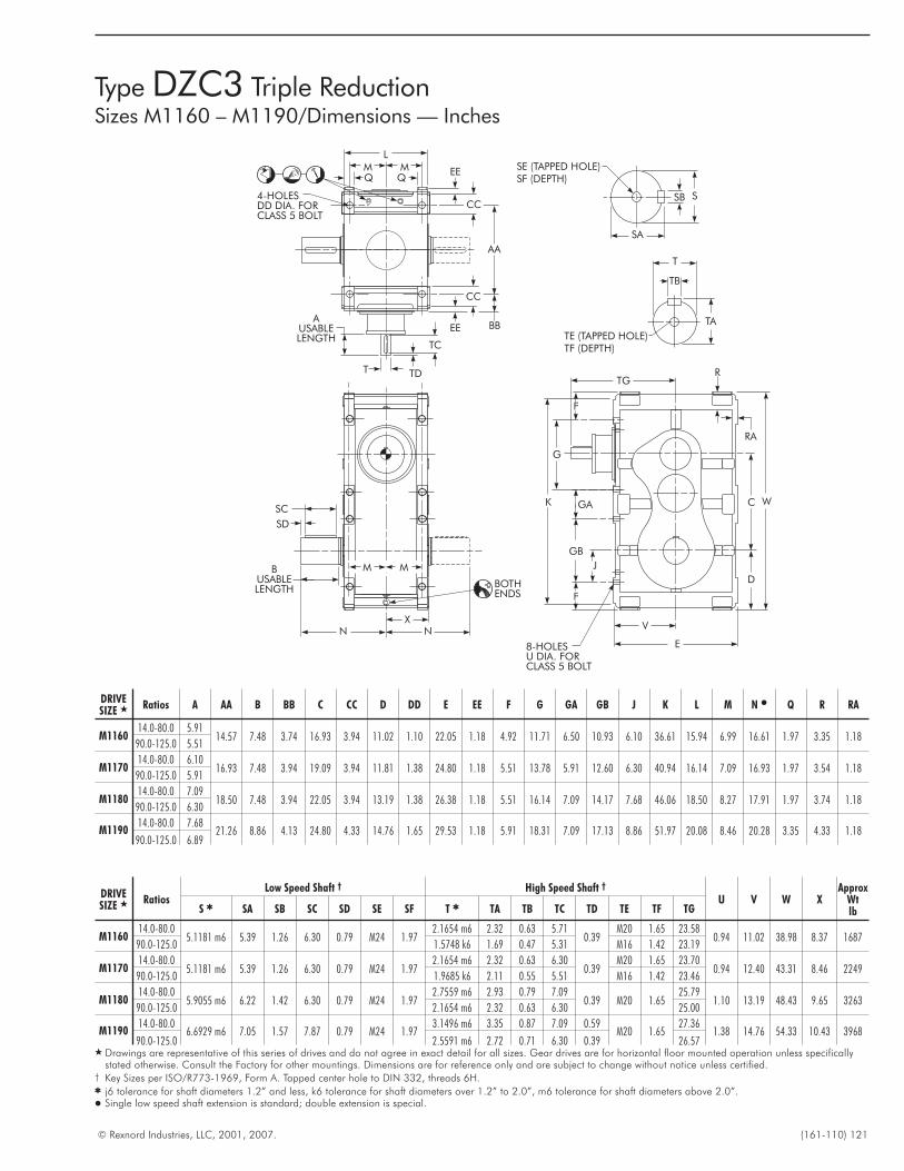
© Rexnord Industries, LLC, 2001, 2007. (161-110) 121
Type DZC3 Triple ReductionSizes M1160 – M1190/Dimensions — Inches
TE (TAPPED HOLE)TF (DEPTH)
TA
TB
T
SA
SB S
SE (TAPPED HOLE)SF (DEPTH)
W
D
V
E
F
8-HOLESU DIA. FORCLASS 5 BOLT
G
GA
GB
F
K
J
C
TGT
TC
TD
AUSABLELENGTH
AA
4-HOLESDD DIA. FORCLASS 5 BOLT
BBEE
CC
EE
CC
MMQ Q
L
X
MM
SD
SC
BUSABLELENGTH
N N
BOTHENDS
R
RA
DRIVESIZE � Ratios A AA B BB C CC D DD E EE F G GA GB J K L M N � Q R RA
M116014.0-80.0 5.91
14.57 7.48 3.74 16.93 3.94 11.02 1.10 22.05 1.18 4.92 11.71 6.50 10.93 6.10 36.61 15.94 6.99 16.61 1.97 3.35 1.1890.0-125.0 5.51
M117014.0-80.0 6.10
16.93 7.48 3.94 19.09 3.94 11.81 1.38 24.80 1.18 5.51 13.78 5.91 12.60 6.30 40.94 16.14 7.09 16.93 1.97 3.54 1.1890.0-125.0 5.91
M118014.0-80.0 7.09
18.50 7.48 3.94 22.05 3.94 13.19 1.38 26.38 1.18 5.51 16.14 7.09 14.17 7.68 46.06 18.50 8.27 17.91 1.97 3.74 1.1890.0-125.0 6.30
M119014.0-80.0 7.68
21.26 8.86 4.13 24.80 4.33 14.76 1.65 29.53 1.18 5.91 18.31 7.09 17.13 8.86 51.97 20.08 8.46 20.28 3.35 4.33 1.1890.0-125.0 6.89
DRIVESIZE � Ratios
Low Speed Shaft † High Speed Shaft †
U V W XApprox
WtlbS � SA SB SC SD SE SF T � TA TB TC TD TE TF TG
M116014.0-80.0
5.1181 m6 5.39 1.26 6.30 0.79 M24 1.972.1654 m6 2.32 0.63 5.71
0.39M20 1.65 23.58
0.94 11.02 38.98 8.37 168790.0-125.0 1.5748 k6 1.69 0.47 5.31 M16 1.42 23.19
M117014.0-80.0
5.1181 m6 5.39 1.26 6.30 0.79 M24 1.972.1654 m6 2.32 0.63 6.30
0.39M20 1.65 23.70
0.94 12.40 43.31 8.46 224990.0-125.0 1.9685 k6 2.11 0.55 5.51 M16 1.42 23.46
M118014.0-80.0
5.9055 m6 6.22 1.42 6.30 0.79 M24 1.972.7559 m6 2.93 0.79 7.09
0.39 M20 1.6525.79
1.10 13.19 48.43 9.65 326390.0-125.0 2.1654 m6 2.32 0.63 6.30 25.00
M119014.0-80.0
6.6929 m6 7.05 1.57 7.87 0.79 M24 1.973.1496 m6 3.35 0.87 7.09 0.59
M20 1.6527.36
1.38 14.76 54.33 10.43 396890.0-125.0 2.5591 m6 2.72 0.71 6.30 0.39 26.57
� Drawings are representative of this series of drives and do not agree in exact detail for all sizes. Gear drives are for horizontal floor mounted operation unless specificallystated otherwise. Consult the Factory for other mountings. Dimensions are for reference only and are subject to change without notice unless certified.
† Key Sizes per ISO/R773-1969, Form A. Tapped center hole to DIN 332, threads 6H.� j6 tolerance for shaft diameters 1.2” and less, k6 tolerance for shaft diameters over 1.2” to 2.0”, m6 tolerance for shaft diameters above 2.0”.� Single low speed shaft extension is standard; double extension is special.
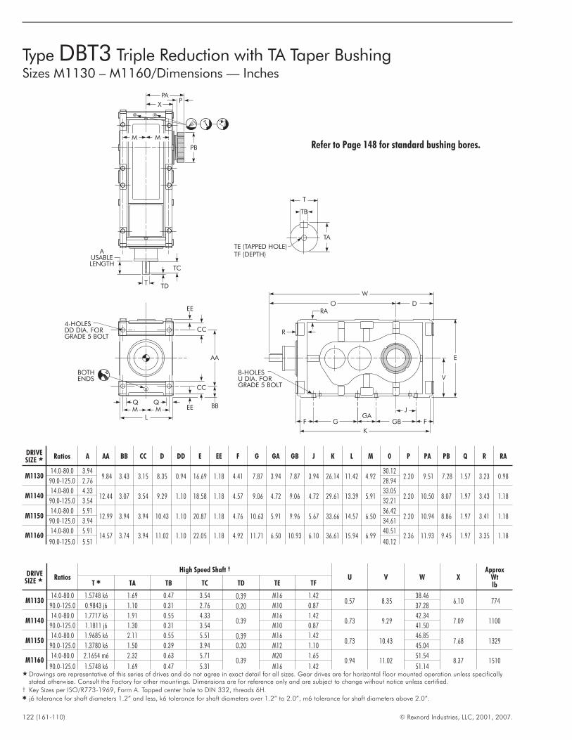
122 (161-110) © Rexnord Industries, LLC, 2001, 2007.
TE (TAPPED HOLE)TF (DEPTH)
TA
TB
T
W
O D
V
E
F
8-HOLESU DIA. FORGRADE 5 BOLT
GGA
GB F
K
J
X
T
TC
TD
AUSABLELENGTH
PPA
PB
MM
AA
4-HOLESDD DIA. FORGRADE 5 BOLT
BBEE
CC
EE
CC
BOTHENDS
MMQ Q
L
R
RA
Type DBT3 Triple Reduction with TA Taper BushingSizes M1130 – M1160/Dimensions — Inches
Refer to Page 148 for standard bushing bores.
DRIVESIZE � Ratios A AA BB CC D DD E EE F G GA GB J K L M 0 P PA PB Q R RA
M113014.0-80.0 3.94
9.84 3.43 3.15 8.35 0.94 16.69 1.18 4.41 7.87 3.94 7.87 3.94 26.14 11.42 4.9230.12
2.20 9.51 7.28 1.57 3.23 0.9890.0-125.0 2.76 28.94
M114014.0-80.0 4.33
12.44 3.07 3.54 9.29 1.10 18.58 1.18 4.57 9.06 4.72 9.06 4.72 29.61 13.39 5.9133.05
2.20 10.50 8.07 1.97 3.43 1.1890.0-125.0 3.54 32.21
M115014.0-80.0 5.91
12.99 3.94 3.94 10.43 1.10 20.87 1.18 4.76 10.63 5.91 9.96 5.67 33.66 14.57 6.5036.42
2.20 10.94 8.86 1.97 3.41 1.1890.0-125.0 3.94 34.61
M116014.0-80.0 5.91
14.57 3.74 3.94 11.02 1.10 22.05 1.18 4.92 11.71 6.50 10.93 6.10 36.61 15.94 6.9940.51
2.36 11.93 9.45 1.97 3.35 1.1890.0-125.0 5.51 40.12
DRIVESIZE � Ratios
High Speed Shaft †
U V W XApprox
WtlbT � TA TB TC TD TE TF
M113014.0-80.0 1.5748 k6 1.69 0.47 3.54 0.39 M16 1.42
0.57 8.3538.46
6.10 77490.0-125.0 0.9843 j6 1.10 0.31 2.76 0.20 M10 0.87 37.28
M114014.0-80.0 1.7717 k6 1.91 0.55 4.33
0.39M16 1.42
0.73 9.2942.34
7.09 110090.0-125.0 1.1811 j6 1.30 0.31 3.54 M10 0.87 41.50
M115014.0-80.0 1.9685 k6 2.11 0.55 5.51 0.39 M16 1.42
0.73 10.4346.85
7.68 132990.0-125.0 1.3780 k6 1.50 0.39 3.94 0.20 M12 1.10 45.04
M116014.0-80.0 2.1654 m6 2.32 0.63 5.71
0.39M20 1.65
0.94 11.0251.54
8.37 151090.0-125.0 1.5748 k6 1.69 0.47 5.31 M16 1.42 51.14
� Drawings are representative of this series of drives and do not agree in exact detail for all sizes. Gear drives are for horizontal floor mounted operation unless specificallystated otherwise. Consult the Factory for other mountings. Dimensions are for reference only and are subject to change without notice unless certified.
† Key Sizes per ISO/R773-1969, Form A. Tapped center hole to DIN 332, threads 6H.� j6 tolerance for shaft diameters 1.2” and less, k6 tolerance for shaft diameters over 1.2” to 2.0”, m6 tolerance for shaft diameters above 2.0”.
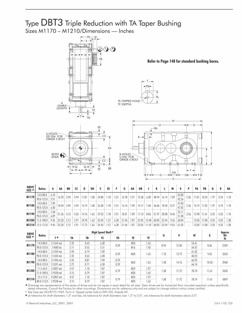
© Rexnord Industries, LLC, 2001, 2007. (161-110) 123
TE (TAPPED HOLE)TF (DEPTH)
TA
TB
T
W
O D
V
E
F
8-HOLESU DIA. FORGRADE 5 BOLT
GGA
GB F
K
J
X
T
TC
TD
AUSABLELENGTH
PPA
PB
MM
AA
4-HOLESDD DIA. FORGRADE 5 BOLT
BBEE
CC
EE
CC
BOTHENDS
MMQ Q
L
R
RA
Type DBT3 Triple Reduction with TA Taper BushingSizes M1170 – M1210/Dimensions — Inches
Refer to Page 148 for standard bushing bores.
DRIVESIZE � Ratios A AA BB CC D DD E EE F G GA GB J K L M 0 P PA PB Q R RA
M117014.0-80.0 6.10
16.93 3.94 3.94 11.81 1.38 24.80 1.18 5.51 13.78 5.91 12.60 6.30 40.94 16.14 7.0942.80
2.36 11.81 10.24 1.97 3.54 1.1890.0-125.0 5.91 42.56
M118014.0-80.0 7.09
18.50 3.94 3.94 13.19 1.38 26.38 1.18 5.51 16.14 7.09 14.17 7.68 46.06 18.50 8.2747.83
2.36 13.19 11.02 1.97 3.74 1.1890.0-125.0 6.30 47.05
M119014.0-80.0 7.68
21.26 4.13 4.33 14.76 1.65 29.53 1.18 5.91 18.31 7.09 17.13 8.86 51.97 20.08 8.4652.17
2.56 13.98 11.61 3.35 4.33 1.1890.0-125.0 6.89 51.38
M1200 11.2-100.0 9.45 25.20 5.12 5.91 18.70 1.65 35.43 1.57 6.30 21.46 7.87 22.05 12.40 60.83 22.44 9.65 60.04 . . . 13.03 11.00 3.35 4.33 1.38
M1210 12.5-112.0 9.45 25.20 5.12 5.91 17.72 1.65 35.43 1.57 6.30 21.46 7.87 22.05 11.42 60.83 22.44 9.65 61.02 . . . 13.03 11.00 3.35 4.33 1.38
DRIVESIZE � Ratios
High Speed Shaft †
U V W XApprox
WtlbT � TA TB TC TD TE TF
M117014.0-80.0 2.1654 m6 2.32 0.63 6.30
0.39M20 1.65
0.94 12.4054.61
8.46 224990.0-125.0 1.9685 k6 2.11 0.55 5.51 M16 1.42 54.37
M118014.0-80.0 2.7559 m6 2.93 0.79 7.09
0.39 M20 1.65 1.10 13.1961.02
9.65 326390.0-125.0 2.1654 m6 2.32 0.63 6.30 60.24
M119014.0-80.0 3.1496 m6 3.35 0.87 7.09 0.59
M20 1.65 1.38 14.7666.93
10.43 396890.0-125.0 2.5591 m6 2.72 0.71 6.30 0.39 66.14
M120011.2-63.0 4.3307 m6 4.57 1.10 7.87
0.79M24 1.97
1.38 17.72 78.74 11.61 565071.0-100.0 2.9528 m6 3.15 0.79 7.87 M20 1.65
M121012.5-71.0 4.3307 m6 4.57 1.10 7.87
0.79M24 1.97
1.38 17.72 78.74 11.61 584980.0-112.0 2.9528 m6 3.15 0.79 7.87 M20 1.65
� Drawings are representative of this series of drives and do not agree in exact detail for all sizes. Gear drives are for horizontal floor mounted operation unless specificallystated otherwise. Consult the Factory for other mountings. Dimensions are for reference only and are subject to change without notice unless certified.
† Key Sizes per ISO/R773-1969, Form A. Tapped center hole to DIN 332, threads 6H.� j6 tolerance for shaft diameters 1.2” and less, k6 tolerance for shaft diameters over 1.2” to 2.0”, m6 tolerance for shaft diameters above 2.0”.
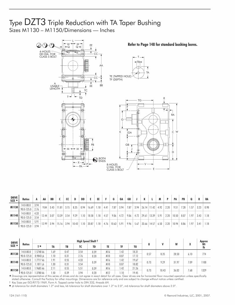
124 (161-110) © Rexnord Industries, LLC, 2001, 2007.
Type DZT3 Triple Reduction with TA Taper BushingSizes M1130 – M1150/Dimensions — Inches
TE (TAPPED HOLE)TF (DEPTH)
TA
TB
T
W
D
V
E
F
8-HOLESU DIA. FORCLASS 5 BOLT
G
GA
GB
F
K
J
C
TG
T
TC
TD
AUSABLELENGTH
AA
4-HOLESDD DIA. FORCLASS 5 BOLT
BBEE
CC
EE
CC
MMQ Q
L
XP
PA
PB
MM
BOTHENDS
R
RA
Refer to Page 148 for standard bushing bores.
DRIVESIZE � Ratios A AA BB C CC D DD E EE F G GA GB J K L M P PA PB Q R RA
M113014.0-80.0 3.94
9.84 3.43 11.81 3.15 8.35 0.94 16.69 1.18 4.41 7.87 3.94 7.87 3.94 26.14 11.42 4.92 2.20 9.51 7.28 1.57 3.23 0.9890.0-125.0 2.76
M114014.0-80.0 4.33
12.44 3.07 13.39 3.54 9.29 1.10 18.58 1.18 4.57 9.06 4.72 9.06 4.72 29.61 13.39 5.91 2.20 10.50 8.07 1.97 3.43 1.1890.0-125.0 3.54
M115014.0-80.0 5.91
12.99 3.94 15.16 3.94 10.43 1.10 20.87 1.18 4.76 10.63 5.91 9.96 5.67 33.66 14.57 6.50 2.20 10.94 8.86 1.97 3.41 1.1890.0-125.0 3.94
DRIVESIZE � Ratios
High Speed Shaft †
U V W XApprox
WtlbT � TA TB TC TD TE TF TG
M113014.0-80.0 1.5748 k6 1.69 0.47 3.54 0.39 M16 1.42 18.31
0.57 8.35 28.50 6.10 77490.0-125.0 0.9843 j6 1.10 0.31 2.76 0.20 M10 0.87 17.12
M114014.0-80.0 1.7717 k6 1.91 0.55 4.33
0.39M16 1.42 19.67
0.73 9.29 31.97 7.09 110090.0-125.0 1.1811 j6 1.30 0.31 3.54 M10 0.87 18.82
M115014.0-80.0 1.9685 k6 2.11 0.55 5.51 0.39 M16 1.42 21.26
0.73 10.43 36.02 7.68 132990.0-125.0 1.3780 k6 1.50 0.39 3.94 0.20 M12 1.10 19.45
� Drawings are representative of this series of drives and do not agree in exact detail for all sizes. Gear drives are for horizontal floor mounted operation unless specificallystated otherwise. Consult the Factory for other mountings. Dimensions are for reference only and are subject to change without notice unless certified.
† Key Sizes per ISO/R773-1969, Form A. Tapped center hole to DIN 332, threads 6H.� j6 tolerance for shaft diameters 1.2” and less, k6 tolerance for shaft diameters over 1.2” to 2.0”, m6 tolerance for shaft diameters above 2.0”.
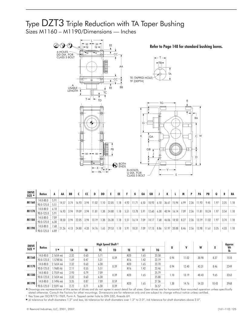
© Rexnord Industries, LLC, 2001, 2007. (161-110) 125
Type DZT3 Triple Reduction with TA Taper BushingSizes M1160 – M1190/Dimensions — Inches
TE (TAPPED HOLE)TF (DEPTH)
TA
TB
T
W
D
V
E
F
8-HOLESU DIA. FORCLASS 5 BOLT
G
GA
GB
F
K
J
C
TG
T
TC
TD
AUSABLELENGTH
AA
4-HOLESDD DIA. FORCLASS 5 BOLT
BBEE
CC
EE
CC
MMQ Q
L
XP
PA
PB
MM
BOTHENDS
R
RA
Refer to Page 148 for standard bushing bores.
DRIVESIZE � Ratios A AA BB C CC D DD E EE F G GA GB J K L M P PA PB Q R RA
M116014.0-80.0 5.91
14.57 3.74 16.93 3.94 11.02 1.10 22.05 1.18 4.92 11.71 6.50 10.93 6.10 36.61 15.94 6.99 2.36 11.93 9.45 1.97 3.35 1.1890.0-125.0 5.51
M117014.0-80.0 6.10
16.93 3.94 19.09 3.94 11.81 1.38 24.80 1.18 5.51 13.78 5.91 12.60 6.30 40.94 16.14 7.09 2.36 11.81 10.24 1.97 3.54 1.1890.0-125.0 5.91
M118014.0-80.0 7.09
18.50 3.94 22.05 3.94 13.19 1.38 26.38 1.18 5.51 16.14 7.09 14.17 7.68 46.06 18.50 8.27 2.36 13.19 11.02 1.97 3.74 1.1890.0-125.0 6.30
M119014.0-80.0 7.68
21.26 4.13 24.80 4.33 14.76 1.65 29.53 1.18 5.91 18.31 7.09 17.13 8.86 51.97 20.08 8.46 2.56 13.98 11.61 3.35 4.33 1.1890.0-125.0 6.89
DRIVESIZE � Ratios
High Speed Shaft †
U V W XApprox
WtlbT � TA TB TC TD TE TF TG
M116014.0-80.0 2.1654 m6 2.32 0.63 5.71
0.39M20 1.65 23.58
0.94 11.02 38.98 8.37 151090.0-125.0 1.5748 k6 1.69 0.47 5.31 M16 1.42 23.19
M117014.0-80.0 2.1654 m6 2.32 0.63 6.30
0.39M20 1.65 23.70
0.94 12.40 43.31 8.46 224990.0-125.0 1.9685 k6 2.11 0.55 5.51 M16 1.42 23.46
M118014.0-80.0 2.7559 m6 2.93 0.79 7.09
0.39 M20 1.6525.79
1.10 13.19 48.43 9.65 326390.0-125.0 2.1654 m6 2.32 0.63 6.30 25.00
M119014.0-80.0 3.1496 m6 3.35 0.87 7.09 0.59
M20 1.6527.36
1.38 14.76 54.33 10.43 396890.0-125.0 2.5591 m6 2.72 0.71 6.30 0.39 26.57
� Drawings are representative of this series of drives and do not agree in exact detail for all sizes. Gear drives are for horizontal floor mounted operation unless specificallystated otherwise. Consult the Factory for other mountings. Dimensions are for reference only and are subject to change without notice unless certified.
† Key Sizes per ISO/R773-1969, Form A. Tapped center hole to DIN 332, threads 6H.� j6 tolerance for shaft diameters 1.2” and less, k6 tolerance for shaft diameters over 1.2” to 2.0”, m6 tolerance for shaft diameters above 2.0”.
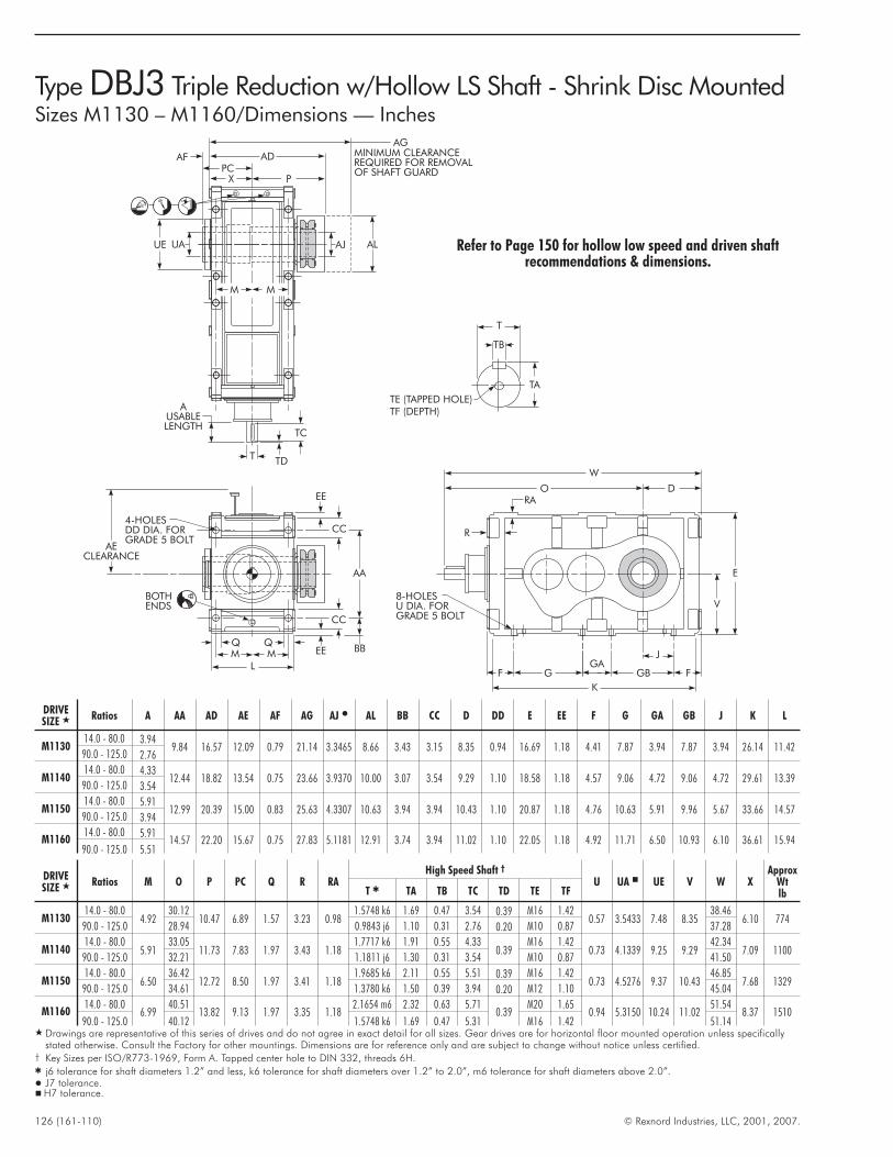
126 (161-110) © Rexnord Industries, LLC, 2001, 2007.
Type DBJ3 Triple Reduction w/Hollow LS Shaft - Shrink Disc MountedSizes M1130 – M1160/Dimensions — Inches
TE (TAPPED HOLE)TF (DEPTH)
TA
TB
T
W
O D
V
E
F
8-HOLESU DIA. FORGRADE 5 BOLT
GGA
GB F
K
J
T
TC
TD
AUSABLELENGTH
MM
AA
4-HOLESDD DIA. FORGRADE 5 BOLT
BBEE
CC
EE
CC
BOTHENDS
MMQ Q
L
R
RA
AECLEARANCE
XPC
P
ADAF MINIMUM CLEARANCEREQUIRED FOR REMOVALOF SHAFT GUARD
AG
UAUE AJ AL
DRIVESIZE � Ratios A AA AD AE AF AG AJ � AL BB CC D DD E EE F G GA GB J K L
M113014.0 - 80.0 3.94
9.84 16.57 12.09 0.79 21.14 3.3465 8.66 3.43 3.15 8.35 0.94 16.69 1.18 4.41 7.87 3.94 7.87 3.94 26.14 11.4290.0 - 125.0 2.76
M114014.0 - 80.0 4.33
12.44 18.82 13.54 0.75 23.66 3.9370 10.00 3.07 3.54 9.29 1.10 18.58 1.18 4.57 9.06 4.72 9.06 4.72 29.61 13.3990.0 - 125.0 3.54
M115014.0 - 80.0 5.91
12.99 20.39 15.00 0.83 25.63 4.3307 10.63 3.94 3.94 10.43 1.10 20.87 1.18 4.76 10.63 5.91 9.96 5.67 33.66 14.5790.0 - 125.0 3.94
M116014.0 - 80.0 5.91
14.57 22.20 15.67 0.75 27.83 5.1181 12.91 3.74 3.94 11.02 1.10 22.05 1.18 4.92 11.71 6.50 10.93 6.10 36.61 15.9490.0 - 125.0 5.51
DRIVESIZE � Ratios M O P PC Q R RA
High Speed Shaft †
U UA � UE V W XApprox
WtlbT � TA TB TC TD TE TF
M113014.0 - 80.0
4.9230.12
10.47 6.89 1.57 3.23 0.981.5748 k6 1.69 0.47 3.54 0.39 M16 1.42
0.57 3.5433 7.48 8.3538.46
6.10 77490.0 - 125.0 28.94 0.9843 j6 1.10 0.31 2.76 0.20 M10 0.87 37.28
M114014.0 - 80.0
5.9133.05
11.73 7.83 1.97 3.43 1.181.7717 k6 1.91 0.55 4.33
0.39M16 1.42
0.73 4.1339 9.25 9.2942.34
7.09 110090.0 - 125.0 32.21 1.1811 j6 1.30 0.31 3.54 M10 0.87 41.50
M115014.0 - 80.0
6.5036.42
12.72 8.50 1.97 3.41 1.181.9685 k6 2.11 0.55 5.51 0.39 M16 1.42
0.73 4.5276 9.37 10.4346.85
7.68 132990.0 - 125.0 34.61 1.3780 k6 1.50 0.39 3.94 0.20 M12 1.10 45.04
M116014.0 - 80.0
6.9940.51
13.82 9.13 1.97 3.35 1.182.1654 m6 2.32 0.63 5.71
0.39M20 1.65
0.94 5.3150 10.24 11.0251.54
8.37 151090.0 - 125.0 40.12 1.5748 k6 1.69 0.47 5.31 M16 1.42 51.14
� Drawings are representative of this series of drives and do not agree in exact detail for all sizes. Gear drives are for horizontal floor mounted operation unless specificallystated otherwise. Consult the Factory for other mountings. Dimensions are for reference only and are subject to change without notice unless certified.
† Key Sizes per ISO/R773-1969, Form A. Tapped center hole to DIN 332, threads 6H.� j6 tolerance for shaft diameters 1.2” and less, k6 tolerance for shaft diameters over 1.2” to 2.0”, m6 tolerance for shaft diameters above 2.0”.� J7 tolerance.� H7 tolerance.
Refer to Page 150 for hollow low speed and driven shaftrecommendations & dimensions.
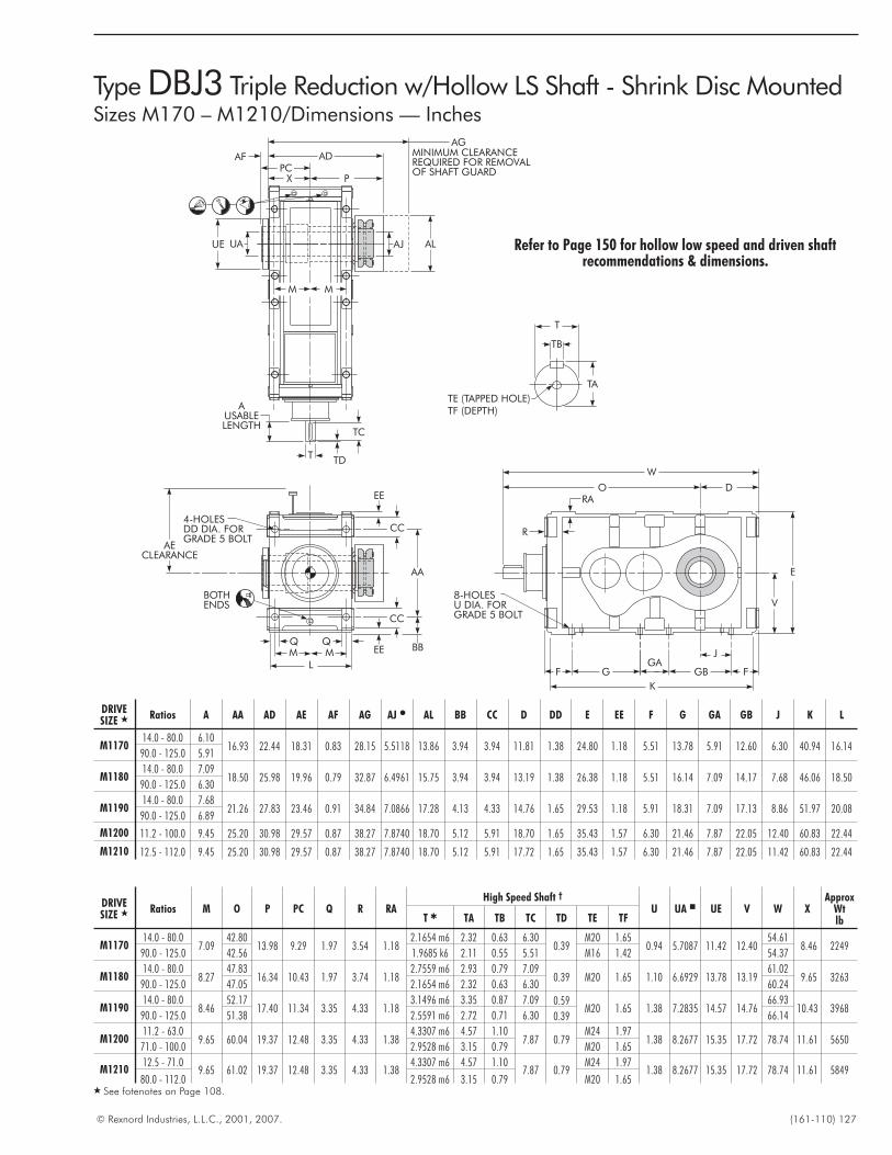
© Rexnord Industries, L.L.C., 2001, 2007. (161-110) 127
Type DBJ3 Triple Reduction w/Hollow LS Shaft - Shrink Disc MountedSizes M170 – M1210/Dimensions — Inches
TE (TAPPED HOLE)TF (DEPTH)
TA
TB
T
W
O D
V
E
F
8-HOLESU DIA. FORGRADE 5 BOLT
GGA
GB F
K
J
T
TC
TD
AUSABLELENGTH
MM
AA
4-HOLESDD DIA. FORGRADE 5 BOLT
BBEE
CC
EE
CC
BOTHENDS
MMQ Q
L
R
RA
AECLEARANCE
XPC
P
ADAF MINIMUM CLEARANCEREQUIRED FOR REMOVALOF SHAFT GUARD
AG
UAUE AJ AL
DRIVESIZE � Ratios A AA AD AE AF AG AJ � AL BB CC D DD E EE F G GA GB J K L
M117014.0 - 80.0 6.10
16.93 22.44 18.31 0.83 28.15 5.5118 13.86 3.94 3.94 11.81 1.38 24.80 1.18 5.51 13.78 5.91 12.60 6.30 40.94 16.1490.0 - 125.0 5.91
M118014.0 - 80.0 7.09
18.50 25.98 19.96 0.79 32.87 6.4961 15.75 3.94 3.94 13.19 1.38 26.38 1.18 5.51 16.14 7.09 14.17 7.68 46.06 18.5090.0 - 125.0 6.30
M119014.0 - 80.0 7.68
21.26 27.83 23.46 0.91 34.84 7.0866 17.28 4.13 4.33 14.76 1.65 29.53 1.18 5.91 18.31 7.09 17.13 8.86 51.97 20.0890.0 - 125.0 6.89
M1200 11.2 - 100.0 9.45 25.20 30.98 29.57 0.87 38.27 7.8740 18.70 5.12 5.91 18.70 1.65 35.43 1.57 6.30 21.46 7.87 22.05 12.40 60.83 22.44
M1210 12.5 - 112.0 9.45 25.20 30.98 29.57 0.87 38.27 7.8740 18.70 5.12 5.91 17.72 1.65 35.43 1.57 6.30 21.46 7.87 22.05 11.42 60.83 22.44
DRIVESIZE � Ratios M O P PC Q R RA
High Speed Shaft †
U UA � UE V W XApprox
WtlbT � TA TB TC TD TE TF
M117014.0 - 80.0
7.0942.80
13.98 9.29 1.97 3.54 1.182.1654 m6 2.32 0.63 6.30
0.39M20 1.65
0.94 5.7087 11.42 12.4054.61
8.46 224990.0 - 125.0 42.56 1.9685 k6 2.11 0.55 5.51 M16 1.42 54.37
M118014.0 - 80.0
8.2747.83
16.34 10.43 1.97 3.74 1.182.7559 m6 2.93 0.79 7.09
0.39 M20 1.65 1.10 6.6929 13.78 13.1961.02
9.65 326390.0 - 125.0 47.05 2.1654 m6 2.32 0.63 6.30 60.24
M119014.0 - 80.0
8.4652.17
17.40 11.34 3.35 4.33 1.183.1496 m6 3.35 0.87 7.09 0.59
M20 1.65 1.38 7.2835 14.57 14.7666.93
10.43 396890.0 - 125.0 51.38 2.5591 m6 2.72 0.71 6.30 0.39 66.14
M120011.2 - 63.0
9.65 60.04 19.37 12.48 3.35 4.33 1.384.3307 m6 4.57 1.10
7.87 0.79M24 1.97
1.38 8.2677 15.35 17.72 78.74 11.61 565071.0 - 100.0 2.9528 m6 3.15 0.79 M20 1.65
M121012.5 - 71.0
9.65 61.02 19.37 12.48 3.35 4.33 1.384.3307 m6 4.57 1.10
7.87 0.79M24 1.97
1.38 8.2677 15.35 17.72 78.74 11.61 584980.0 - 112.0 2.9528 m6 3.15 0.79 M20 1.65
� See fotenotes on Page 108.
Refer to Page 150 for hollow low speed and driven shaftrecommendations & dimensions.
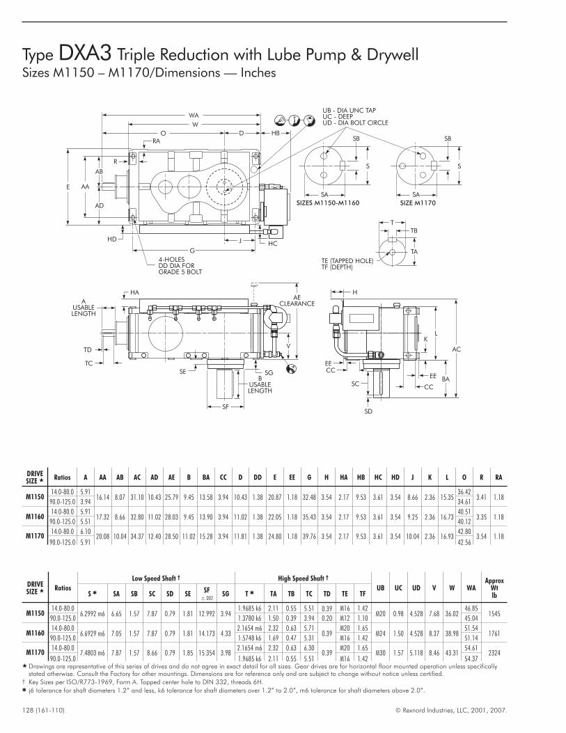
128 (161-110) © Rexnord Industries, LLC, 2001, 2007.
Type DXA3 Triple Reduction with Lube Pump & DrywellSizes M1150 – M1170/Dimensions — Inches
M
MQ
Q
L
EE
W
O D
13.80
WA
W
O D HB
HCJ
G
4-HOLESDD DIA FORGRADE 5 BOLT
HD
AD
AB
AAE
UB - DIA UNC TAPUC - DEEPUD - DIA BOLT CIRCLE
H
L
AC
BA
K
EE
CC
SD
SC
CCEE
AECLEARANCE
V
SGB
USABLELENGTH
SE
SF
TC
TD
AUSABLELENGTH
HA
T
TB
TA
TE (TAPPED HOLE)TF (DEPTH)
S
SA
SB
S
SA
SB
SIZES M1150-M1160 SIZE M1170
R
RA
DRIVESIZE � Ratios A AA AB AC AD AE B BA CC D DD E EE G H HA HB HC HD J K L O R RA
M115014.0-80.0 5.91
16.14 8.07 31.10 10.43 25.79 9.45 13.58 3.94 10.43 1.38 20.87 1.18 32.48 3.54 2.17 9.53 3.61 3.54 8.66 2.36 15.3536.42
3.41 1.1890.0-125.0 3.94 34.61
M116014.0-80.0 5.91
17.32 8.66 32.80 11.02 28.03 9.45 13.90 3.94 11.02 1.38 22.05 1.18 35.43 3.54 2.17 9.53 3.61 3.54 9.25 2.36 16.7340.51
3.35 1.1890.0-125.0 5.51 40.12
M117014.0-80.0 6.10
20.08 10.04 34.37 12.40 28.50 11.02 15.28 3.94 11.81 1.38 24.80 1.18 39.76 3.54 2.17 9.53 3.61 3.54 10.04 2.36 16.9342.80
3.54 1.1890.0-125.0 5.91 42.56
DRIVESIZE � Ratios
Low Speed Shaft † High Speed Shaft †
UB UC UD V W WAApprox
WtlbS � SA SB SC SD SE
SF±.002
SG T � TA TB TC TD TE TF
M115014.0-80.0
6.2992 m6 6.65 1.57 7.87 0.79 1.81 12.992 3.941.9685 k6 2.11 0.55 5.51 0.39 M16 1.42
M20 0.98 4.528 7.68 36.0246.85
154590.0-125.0 1.3780 k6 1.50 0.39 3.94 0.20 M12 1.10 45.04
M116014.0-80.0
6.6929 m6 7.05 1.57 7.87 0.79 1.81 14.173 4.332.1654 m6 2.32 0.63 5.71
0.39M20 1.65
M24 1.50 4.528 8.37 38.9851.54
176190.0-125.0 1.5748 k6 1.69 0.47 5.31 M16 1.42 51.14
M117014.0-80.0
7.4803 m6 7.87 1.57 8.66 0.79 1.85 15.354 3.982.1654 m6 2.32 0.63 6.30
0.39M20 1.65
M30 1.57 5.118 8.46 43.3154.61
232490.0-125.0 1.9685 k6 2.11 0.55 5.51 M16 1.42 54.37
� Drawings are representative of this series of drives and do not agree in exact detail for all sizes. Gear drives are for horizontal floor mounted operation unless specificallystated otherwise. Consult the Factory for other mountings. Dimensions are for reference only and are subject to change without notice unless certified.
† Key Sizes per ISO/R773-1969, Form A. Tapped center hole to DIN 332, threads 6H.� j6 tolerance for shaft diameters 1.2” and less, k6 tolerance for shaft diameters over 1.2” to 2.0”, m6 tolerance for shaft diameters above 2.0”.
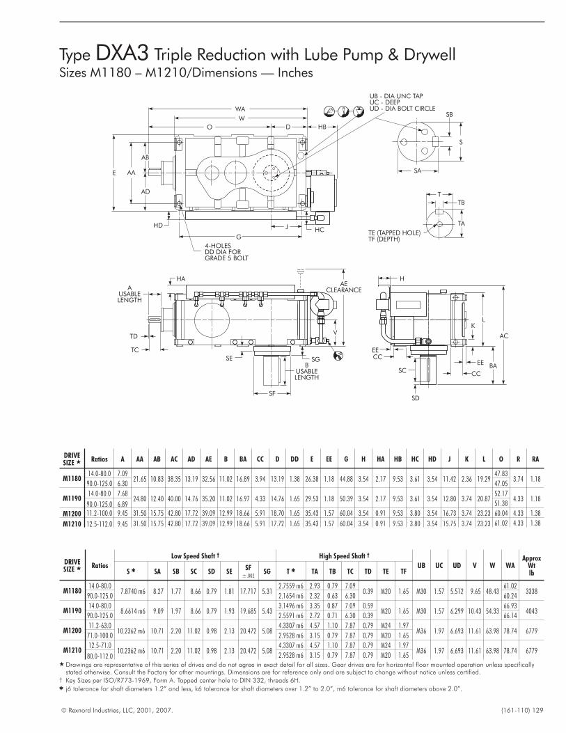
© Rexnord Industries, LLC, 2001, 2007. (161-110) 129
Type DXA3 Triple Reduction with Lube Pump & DrywellSizes M1180 – M1210/Dimensions — Inches
M
MQ
Q
L
EE
W
O D
13.80
WA
W
O D HB
HCJ
G
4-HOLESDD DIA FORGRADE 5 BOLT
HD
AD
AB
AAE
UB - DIA UNC TAPUC - DEEPUD - DIA BOLT CIRCLE
T
TB
TA
H
L
AC
BA
K
EE
CC
SD
SC
CCEE
AECLEARANCE
V
SGB
USABLELENGTH
SE
SF
TC
TD
AUSABLELENGTH
HA
TE (TAPPED HOLE)TF (DEPTH)
S
SA
SB
DRIVESIZE � Ratios A AA AB AC AD AE B BA CC D DD E EE G H HA HB HC HD J K L O R RA
M118014.0-80.0 7.09
21.65 10.83 38.35 13.19 32.56 11.02 16.89 3.94 13.19 1.38 26.38 1.18 44.88 3.54 2.17 9.53 3.61 3.54 11.42 2.36 19.2947.83
3.74 1.1890.0-125.0 6.30 47.05
M119014.0-80.0 7.68
24.80 12.40 40.00 14.76 35.20 11.02 16.97 4.33 14.76 1.65 29.53 1.18 50.39 3.54 2.17 9.53 3.61 3.54 12.80 3.74 20.8752.17
4.33 1.1890.0-125.0 6.89 51.38
M1200 11.2-100.0 9.45 31.50 15.75 42.80 17.72 39.09 12.99 18.66 5.91 18.70 1.65 35.43 1.57 60.04 3.54 0.91 9.53 3.80 3.54 16.73 3.74 23.23 60.04 4.33 1.38
M1210 12.5-112.0 9.45 31.50 15.75 42.80 17.72 39.09 12.99 18.66 5.91 17.72 1.65 35.43 1.57 60.04 3.54 0.91 9.53 3.80 3.54 15.75 3.74 23.23 61.02 4.33 1.38
DRIVESIZE � Ratios
Low Speed Shaft † High Speed Shaft †
UB UC UD V W WAApprox
WtlbS � SA SB SC SD SE
SF±.002
SG T � TA TB TC TD TE TF
M118014.0-80.0
7.8740 m6 8.27 1.77 8.66 0.79 1.81 17.717 5.312.7559 m6 2.93 0.79 7.09
0.39 M20 1.65 M30 1.57 5.512 9.65 48.4361.02
333890.0-125.0 2.1654 m6 2.32 0.63 6.30 60.24
M119014.0-80.0
8.6614 m6 9.09 1.97 8.66 0.79 1.93 19.685 5.433.1496 m6 3.35 0.87 7.09 0.59
M20 1.65 M30 1.57 6.299 10.43 54.3366.93
404390.0-125.0 2.5591 m6 2.72 0.71 6.30 0.39 66.14
M120011.2-63.0
10.2362 m6 10.71 2.20 11.02 0.98 2.13 20.472 5.084.3307 m6 4.57 1.10 7.87 0.79 M24 1.97
M36 1.97 6.693 11.61 63.98 78.74 677971.0-100.0 2.9528 m6 3.15 0.79 7.87 0.79 M20 1.65
M121012.5-71.0
10.2362 m6 10.71 2.20 11.02 0.98 2.13 20.472 5.084.3307 m6 4.57 1.10 7.87 0.79 M24 1.97
M36 1.97 6.693 11.61 63.98 78.74 677980.0-112.0 2.9528 m6 3.15 0.79 7.87 0.79 M20 1.65
� Drawings are representative of this series of drives and do not agree in exact detail for all sizes. Gear drives are for horizontal floor mounted operation unless specificallystated otherwise. Consult the Factory for other mountings. Dimensions are for reference only and are subject to change without notice unless certified.
† Key Sizes per ISO/R773-1969, Form A. Tapped center hole to DIN 332, threads 6H.� j6 tolerance for shaft diameters 1.2” and less, k6 tolerance for shaft diameters over 1.2” to 2.0”, m6 tolerance for shaft diameters above 2.0”.
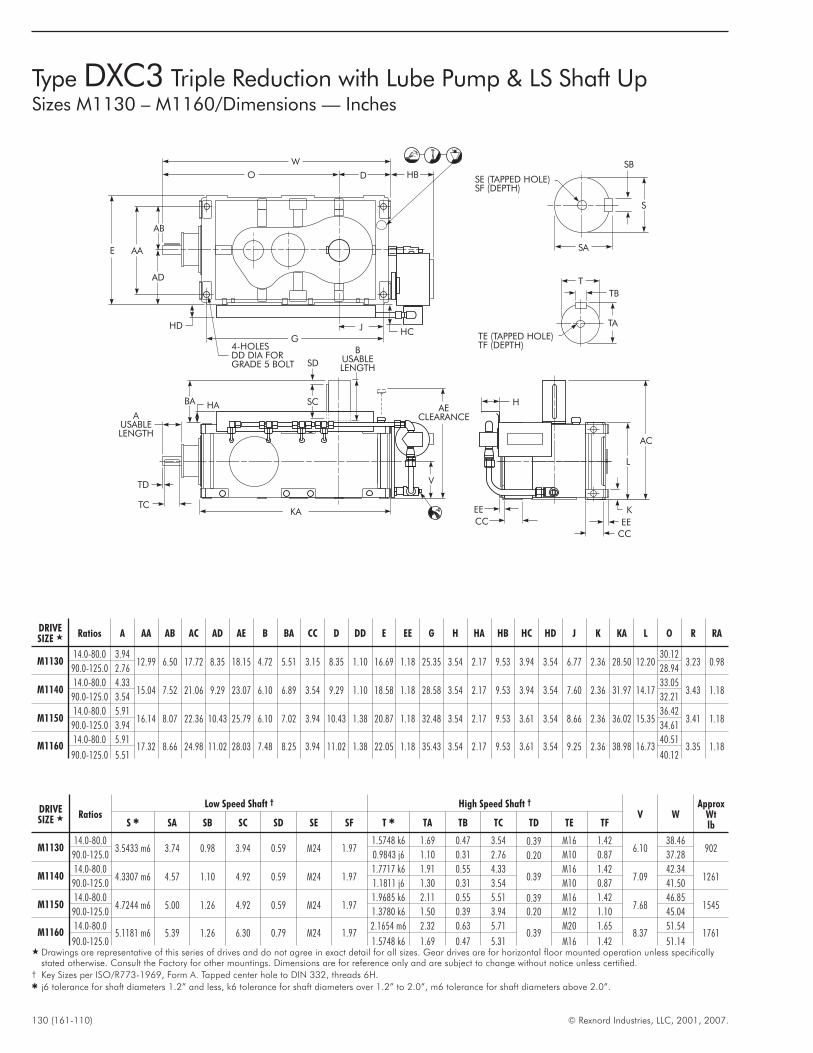
130 (161-110) © Rexnord Industries, LLC, 2001, 2007.
Type DXC3 Triple Reduction with Lube Pump & LS Shaft UpSizes M1130 – M1160/Dimensions — Inches
M
MQ
Q
L
EE
SE (TAPPED HOLE)SF (DEPTH)
SB
S
SA
T
TB
TA
AC
L
K
EE
CC
CC
EE
HAE
CLEARANCE
V
KA
TE (TAPPED HOLE)TF (DEPTH)
BUSABLELENGTH
SC
SD
TC
TD
AUSABLELENGTH
BA HA
4-HOLESDD DIA FORGRADE 5 BOLT
G
JHC
HD
AD
AB
AAE
W
O D HB
DRIVESIZE � Ratios A AA AB AC AD AE B BA CC D DD E EE G H HA HB HC HD J K KA L O R RA
M113014.0-80.0 3.94
12.99 6.50 17.72 8.35 18.15 4.72 5.51 3.15 8.35 1.10 16.69 1.18 25.35 3.54 2.17 9.53 3.94 3.54 6.77 2.36 28.50 12.2030.12
3.23 0.9890.0-125.0 2.76 28.94
M114014.0-80.0 4.33
15.04 7.52 21.06 9.29 23.07 6.10 6.89 3.54 9.29 1.10 18.58 1.18 28.58 3.54 2.17 9.53 3.94 3.54 7.60 2.36 31.97 14.1733.05
3.43 1.1890.0-125.0 3.54 32.21
M115014.0-80.0 5.91
16.14 8.07 22.36 10.43 25.79 6.10 7.02 3.94 10.43 1.38 20.87 1.18 32.48 3.54 2.17 9.53 3.61 3.54 8.66 2.36 36.02 15.3536.42
3.41 1.1890.0-125.0 3.94 34.61
M116014.0-80.0 5.91
17.32 8.66 24.98 11.02 28.03 7.48 8.25 3.94 11.02 1.38 22.05 1.18 35.43 3.54 2.17 9.53 3.61 3.54 9.25 2.36 38.98 16.7340.51
3.35 1.1890.0-125.0 5.51 40.12
DRIVESIZE � Ratios
Low Speed Shaft † High Speed Shaft †
V WApprox
WtlbS � SA SB SC SD SE SF T � TA TB TC TD TE TF
M113014.0-80.0
3.5433 m6 3.74 0.98 3.94 0.59 M24 1.971.5748 k6 1.69 0.47 3.54 0.39 M16 1.42
6.1038.46
90290.0-125.0 0.9843 j6 1.10 0.31 2.76 0.20 M10 0.87 37.28
M114014.0-80.0
4.3307 m6 4.57 1.10 4.92 0.59 M24 1.971.7717 k6 1.91 0.55 4.33
0.39M16 1.42
7.0942.34
126190.0-125.0 1.1811 j6 1.30 0.31 3.54 M10 0.87 41.50
M115014.0-80.0
4.7244 m6 5.00 1.26 4.92 0.59 M24 1.971.9685 k6 2.11 0.55 5.51 0.39 M16 1.42
7.6846.85
154590.0-125.0 1.3780 k6 1.50 0.39 3.94 0.20 M12 1.10 45.04
M116014.0-80.0
5.1181 m6 5.39 1.26 6.30 0.79 M24 1.972.1654 m6 2.32 0.63 5.71
0.39M20 1.65
8.3751.54
176190.0-125.0 1.5748 k6 1.69 0.47 5.31 M16 1.42 51.14
� Drawings are representative of this series of drives and do not agree in exact detail for all sizes. Gear drives are for horizontal floor mounted operation unless specificallystated otherwise. Consult the Factory for other mountings. Dimensions are for reference only and are subject to change without notice unless certified.
† Key Sizes per ISO/R773-1969, Form A. Tapped center hole to DIN 332, threads 6H.� j6 tolerance for shaft diameters 1.2” and less, k6 tolerance for shaft diameters over 1.2” to 2.0”, m6 tolerance for shaft diameters above 2.0”.
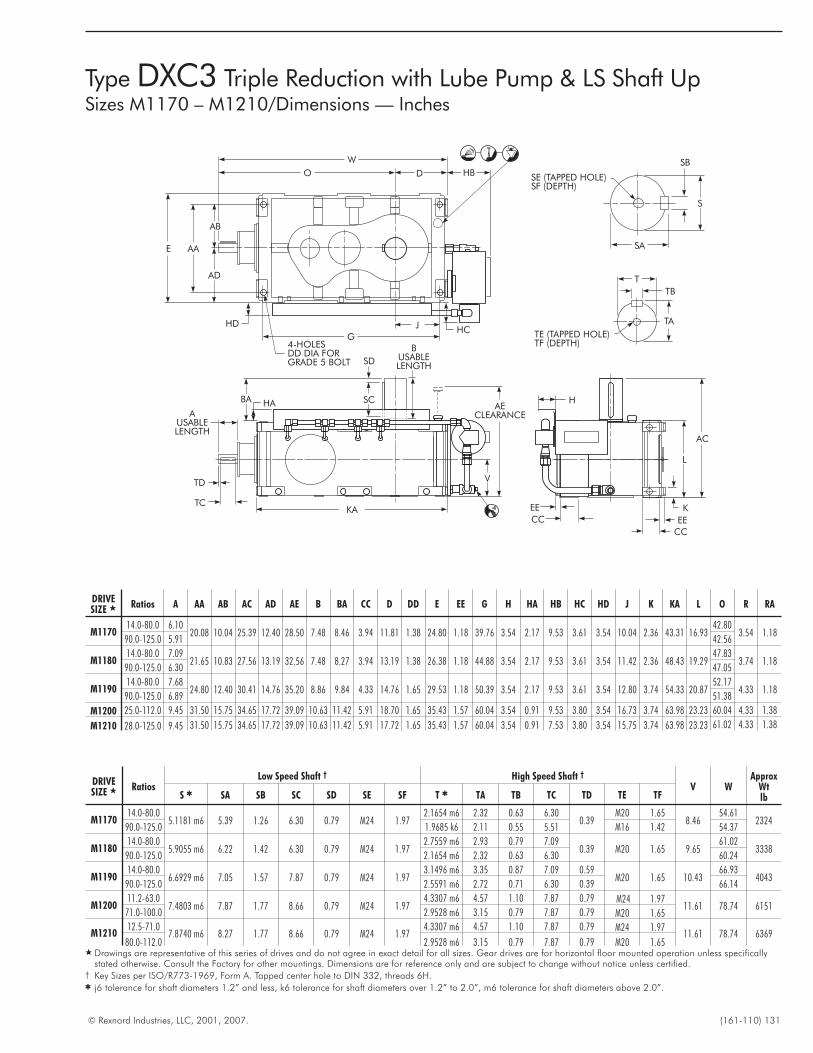
© Rexnord Industries, LLC, 2001, 2007. (161-110) 131
Type DXC3 Triple Reduction with Lube Pump & LS Shaft UpSizes M1170 – M1210/Dimensions — Inches
M
MQ
Q
L
EE
SE (TAPPED HOLE)SF (DEPTH)
SB
S
SA
T
TB
TA
AC
L
K
EE
CC
CC
EE
HAE
CLEARANCE
V
KA
TE (TAPPED HOLE)TF (DEPTH)
BUSABLELENGTH
SC
SD
TC
TD
AUSABLELENGTH
BA HA
4-HOLESDD DIA FORGRADE 5 BOLT
G
JHC
HD
AD
AB
AAE
W
O D HB
DRIVESIZE � Ratios A AA AB AC AD AE B BA CC D DD E EE G H HA HB HC HD J K KA L O R RA
M117014.0-80.0 6.10
20.08 10.04 25.39 12.40 28.50 7.48 8.46 3.94 11.81 1.38 24.80 1.18 39.76 3.54 2.17 9.53 3.61 3.54 10.04 2.36 43.31 16.9342.80
3.54 1.1890.0-125.0 5.91 42.56
M118014.0-80.0 7.09
21.65 10.83 27.56 13.19 32.56 7.48 8.27 3.94 13.19 1.38 26.38 1.18 44.88 3.54 2.17 9.53 3.61 3.54 11.42 2.36 48.43 19.2947.83
3.74 1.1890.0-125.0 6.30 47.05
M119014.0-80.0 7.68
24.80 12.40 30.41 14.76 35.20 8.86 9.84 4.33 14.76 1.65 29.53 1.18 50.39 3.54 2.17 9.53 3.61 3.54 12.80 3.74 54.33 20.8752.17
4.33 1.1890.0-125.0 6.89 51.38
M1200 25.0-112.0 9.45 31.50 15.75 34.65 17.72 39.09 10.63 11.42 5.91 18.70 1.65 35.43 1.57 60.04 3.54 0.91 9.53 3.80 3.54 16.73 3.74 63.98 23.23 60.04 4.33 1.38
M1210 28.0-125.0 9.45 31.50 15.75 34.65 17.72 39.09 10.63 11.42 5.91 17.72 1.65 35.43 1.57 60.04 3.54 0.91 7.53 3.80 3.54 15.75 3.74 63.98 23.23 61.02 4.33 1.38
DRIVESIZE � Ratios
Low Speed Shaft † High Speed Shaft †
V WApprox
WtlbS � SA SB SC SD SE SF T � TA TB TC TD TE TF
M117014.0-80.0
5.1181 m6 5.39 1.26 6.30 0.79 M24 1.972.1654 m6 2.32 0.63 6.30
0.39M20 1.65
8.4654.61
232490.0-125.0 1.9685 k6 2.11 0.55 5.51 M16 1.42 54.37
M118014.0-80.0
5.9055 m6 6.22 1.42 6.30 0.79 M24 1.972.7559 m6 2.93 0.79 7.09
0.39 M20 1.65 9.6561.02
333890.0-125.0 2.1654 m6 2.32 0.63 6.30 60.24
M119014.0-80.0
6.6929 m6 7.05 1.57 7.87 0.79 M24 1.973.1496 m6 3.35 0.87 7.09 0.59
M20 1.65 10.4366.93
404390.0-125.0 2.5591 m6 2.72 0.71 6.30 0.39 66.14
M120011.2-63.0
7.4803 m6 7.87 1.77 8.66 0.79 M24 1.974.3307 m6 4.57 1.10 7.87 0.79 M24 1.97
11.61 78.74 615171.0-100.0 2.9528 m6 3.15 0.79 7.87 0.79 M20 1.65
M121012.5-71.0
7.8740 m6 8.27 1.77 8.66 0.79 M24 1.974.3307 m6 4.57 1.10 7.87 0.79 M24 1.97
11.61 78.74 636980.0-112.0 2.9528 m6 3.15 0.79 7.87 0.79 M20 1.65
� Drawings are representative of this series of drives and do not agree in exact detail for all sizes. Gear drives are for horizontal floor mounted operation unless specificallystated otherwise. Consult the Factory for other mountings. Dimensions are for reference only and are subject to change without notice unless certified.
† Key Sizes per ISO/R773-1969, Form A. Tapped center hole to DIN 332, threads 6H.� j6 tolerance for shaft diameters 1.2” and less, k6 tolerance for shaft diameters over 1.2” to 2.0”, m6 tolerance for shaft diameters above 2.0”.
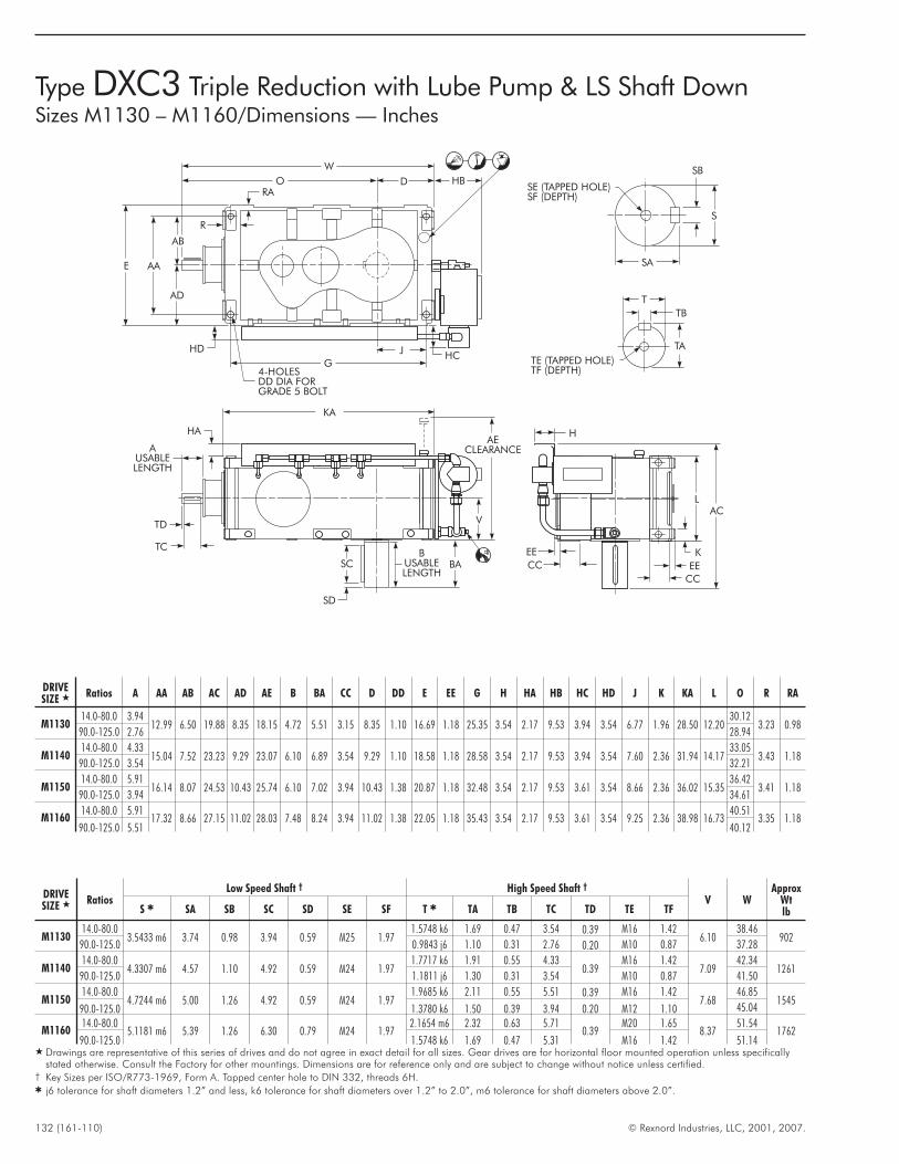
132 (161-110) © Rexnord Industries, LLC, 2001, 2007.
Type DXC3 Triple Reduction with Lube Pump & LS Shaft DownSizes M1130 – M1160/Dimensions — Inches
M
MQ
Q
L
EE
SE (TAPPED HOLE)SF (DEPTH)
SB
S
SA
T
TB
TA
L
K
EE
CC
CC
EE
HAE
CLEARANCE
V
TE (TAPPED HOLE)TF (DEPTH)
TC
TD
AUSABLELENGTH
HA
4-HOLESDD DIA FORGRADE 5 BOLT
G
JHC
HD
AD
AB
AAE
W
O D HB
AC
KA
BUSABLELENGTH
SC
SD
BA
R
RA
DRIVESIZE � Ratios A AA AB AC AD AE B BA CC D DD E EE G H HA HB HC HD J K KA L O R RA
M113014.0-80.0 3.94
12.99 6.50 19.88 8.35 18.15 4.72 5.51 3.15 8.35 1.10 16.69 1.18 25.35 3.54 2.17 9.53 3.94 3.54 6.77 1.96 28.50 12.2030.12
3.23 0.9890.0-125.0 2.76 28.94
M114014.0-80.0 4.33
15.04 7.52 23.23 9.29 23.07 6.10 6.89 3.54 9.29 1.10 18.58 1.18 28.58 3.54 2.17 9.53 3.94 3.54 7.60 2.36 31.94 14.1733.05
3.43 1.1890.0-125.0 3.54 32.21
M115014.0-80.0 5.91
16.14 8.07 24.53 10.43 25.74 6.10 7.02 3.94 10.43 1.38 20.87 1.18 32.48 3.54 2.17 9.53 3.61 3.54 8.66 2.36 36.02 15.3536.42
3.41 1.1890.0-125.0 3.94 34.61
M116014.0-80.0 5.91
17.32 8.66 27.15 11.02 28.03 7.48 8.24 3.94 11.02 1.38 22.05 1.18 35.43 3.54 2.17 9.53 3.61 3.54 9.25 2.36 38.98 16.7340.51
3.35 1.1890.0-125.0 5.51 40.12
DRIVESIZE � Ratios
Low Speed Shaft † High Speed Shaft †
V WApprox
WtlbS � SA SB SC SD SE SF T � TA TB TC TD TE TF
M113014.0-80.0
3.5433 m6 3.74 0.98 3.94 0.59 M25 1.971.5748 k6 1.69 0.47 3.54 0.39 M16 1.42
6.1038.46
90290.0-125.0 0.9843 j6 1.10 0.31 2.76 0.20 M10 0.87 37.28
M114014.0-80.0
4.3307 m6 4.57 1.10 4.92 0.59 M24 1.971.7717 k6 1.91 0.55 4.33
0.39M16 1.42
7.0942.34
126190.0-125.0 1.1811 j6 1.30 0.31 3.54 M10 0.87 41.50
M115014.0-80.0
4.7244 m6 5.00 1.26 4.92 0.59 M24 1.971.9685 k6 2.11 0.55 5.51 0.39 M16 1.42
7.6846.85
154590.0-125.0 1.3780 k6 1.50 0.39 3.94 0.20 M12 1.10 45.04
M116014.0-80.0
5.1181 m6 5.39 1.26 6.30 0.79 M24 1.972.1654 m6 2.32 0.63 5.71
0.39M20 1.65
8.3751.54
176290.0-125.0 1.5748 k6 1.69 0.47 5.31 M16 1.42 51.14
� Drawings are representative of this series of drives and do not agree in exact detail for all sizes. Gear drives are for horizontal floor mounted operation unless specificallystated otherwise. Consult the Factory for other mountings. Dimensions are for reference only and are subject to change without notice unless certified.
† Key Sizes per ISO/R773-1969, Form A. Tapped center hole to DIN 332, threads 6H.� j6 tolerance for shaft diameters 1.2” and less, k6 tolerance for shaft diameters over 1.2” to 2.0”, m6 tolerance for shaft diameters above 2.0”.
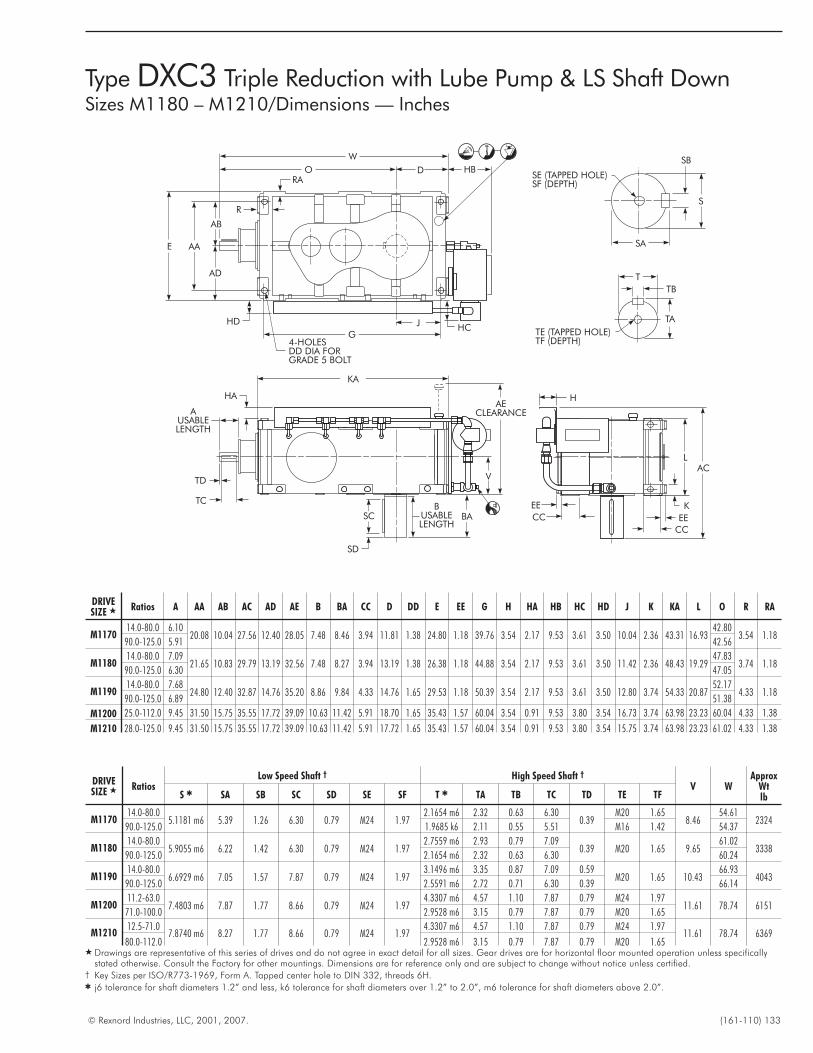
© Rexnord Industries, LLC, 2001, 2007. (161-110) 133
Type DXC3 Triple Reduction with Lube Pump & LS Shaft DownSizes M1180 – M1210/Dimensions — Inches
M
MQ
Q
L
EE
SE (TAPPED HOLE)SF (DEPTH)
SB
S
SA
T
TB
TA
L
K
EE
CC
CC
EE
HAE
CLEARANCE
V
TE (TAPPED HOLE)TF (DEPTH)
TC
TD
AUSABLELENGTH
HA
4-HOLESDD DIA FORGRADE 5 BOLT
G
JHC
HD
AD
AB
AAE
W
O D HB
AC
KA
BUSABLELENGTH
SC
SD
BA
R
RA
DRIVESIZE � Ratios A AA AB AC AD AE B BA CC D DD E EE G H HA HB HC HD J K KA L O R RA
M117014.0-80.0 6.10
20.08 10.04 27.56 12.40 28.05 7.48 8.46 3.94 11.81 1.38 24.80 1.18 39.76 3.54 2.17 9.53 3.61 3.50 10.04 2.36 43.31 16.9342.80
3.54 1.1890.0-125.0 5.91 42.56
M118014.0-80.0 7.09
21.65 10.83 29.79 13.19 32.56 7.48 8.27 3.94 13.19 1.38 26.38 1.18 44.88 3.54 2.17 9.53 3.61 3.50 11.42 2.36 48.43 19.2947.83
3.74 1.1890.0-125.0 6.30 47.05
M119014.0-80.0 7.68
24.80 12.40 32.87 14.76 35.20 8.86 9.84 4.33 14.76 1.65 29.53 1.18 50.39 3.54 2.17 9.53 3.61 3.50 12.80 3.74 54.33 20.8752.17
4.33 1.1890.0-125.0 6.89 51.38
M1200 25.0-112.0 9.45 31.50 15.75 35.55 17.72 39.09 10.63 11.42 5.91 18.70 1.65 35.43 1.57 60.04 3.54 0.91 9.53 3.80 3.54 16.73 3.74 63.98 23.23 60.04 4.33 1.38
M1210 28.0-125.0 9.45 31.50 15.75 35.55 17.72 39.09 10.63 11.42 5.91 17.72 1.65 35.43 1.57 60.04 3.54 0.91 9.53 3.80 3.54 15.75 3.74 63.98 23.23 61.02 4.33 1.38
DRIVESIZE � Ratios
Low Speed Shaft † High Speed Shaft †
V WApprox
WtlbS � SA SB SC SD SE SF T � TA TB TC TD TE TF
M117014.0-80.0
5.1181 m6 5.39 1.26 6.30 0.79 M24 1.972.1654 m6 2.32 0.63 6.30
0.39M20 1.65
8.4654.61
232490.0-125.0 1.9685 k6 2.11 0.55 5.51 M16 1.42 54.37
M118014.0-80.0
5.9055 m6 6.22 1.42 6.30 0.79 M24 1.972.7559 m6 2.93 0.79 7.09
0.39 M20 1.65 9.6561.02
333890.0-125.0 2.1654 m6 2.32 0.63 6.30 60.24
M119014.0-80.0
6.6929 m6 7.05 1.57 7.87 0.79 M24 1.973.1496 m6 3.35 0.87 7.09 0.59
M20 1.65 10.4366.93
404390.0-125.0 2.5591 m6 2.72 0.71 6.30 0.39 66.14
M120011.2-63.0
7.4803 m6 7.87 1.77 8.66 0.79 M24 1.974.3307 m6 4.57 1.10 7.87 0.79 M24 1.97
11.61 78.74 615171.0-100.0 2.9528 m6 3.15 0.79 7.87 0.79 M20 1.65
M121012.5-71.0
7.8740 m6 8.27 1.77 8.66 0.79 M24 1.974.3307 m6 4.57 1.10 7.87 0.79 M24 1.97
11.61 78.74 636980.0-112.0 2.9528 m6 3.15 0.79 7.87 0.79 M20 1.65
� Drawings are representative of this series of drives and do not agree in exact detail for all sizes. Gear drives are for horizontal floor mounted operation unless specificallystated otherwise. Consult the Factory for other mountings. Dimensions are for reference only and are subject to change without notice unless certified.
† Key Sizes per ISO/R773-1969, Form A. Tapped center hole to DIN 332, threads 6H.� j6 tolerance for shaft diameters 1.2” and less, k6 tolerance for shaft diameters over 1.2” to 2.0”, m6 tolerance for shaft diameters above 2.0”.
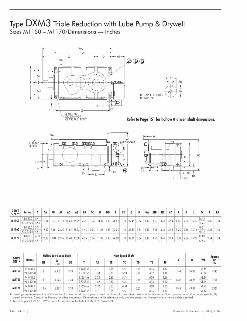
134 (161-110) © Rexnord Industries, LLC, 2001, 2007.
Type DXM3 Triple Reduction with Lube Pump & DrywellSizes M1150 – M1170/Dimensions — Inches
AECLEARANCE
V
SKSH SJ
TC
TD
AUSABLELENGTH
HA
T
TB
TA
TE (TAPPED HOLE)TF (DEPTH)
4-HOLESDD DIA FORCLASS 8,8 BOLT
W
O D
WA
W
O D HB
HC
J
GHD
AD
AB
AAE
R
RA
M
MQ
Q
L
EE
H
L AC
BA
K
EE
CC
CCEE
Refer to Page 151 for hollow & driven shaft dimensions.
DRIVESIZE � Ratios A AA AB AC AD AE BA CC D DD E EE G H HA HB HC HD J K L O R RA
M115014.0-80.0 5.91
16.14 8.07 21.73 10.43 25.79 4.21 3.94 10.43 1.38 20.87 1.18 32.48 3.54 2.17 9.53 3.61 3.54 8.66 2.36 15.3536.42
3.41 1.1890.0-125.0 3.94 34.61
M116014.0-80.0 5.91
17.32 8.66 23.35 11.02 28.03 4.45 3.94 11.02 1.38 22.05 1.18 35.43 3.54 2.17 9.53 3.61 3.54 9.25 2.36 16.7340.51
3.35 1.1890.0-125.0 5.51 40.12
M117014.0-80.0 6.10
20.08 10.04 23.35 12.40 28.50 4.25 3.94 11.81 1.38 24.80 1.18 39.76 3.54 2.17 9.53 3.61 3.54 10.04 2.36 16.9342.80
3.54 1.1890.0-125.0 5.91 42.56
DRIVESIZE � Ratios
Hollow Low Speed Shaft High Speed Shaft †
V W WAApprox
WtlbSH
SJ±.002
SK T TA TB TC TD TE TF
M115014.0-80.0
1.81 12.992 3.941.9685 k6 2.11 0.55 5.51 0.39 M16 1.42
7.68 36.0246.85
154590.0-125.0 1.3780 k6 1.50 0.39 3.94 0.20 M12 1.10 45.04
M116014.0-80.0
1.81 14.173 4.332.1654 m6 2.32 0.63 5.71
0.39M20 1.65
8.37 38.9851.54
176190.0-125.0 1.5748 k6 1.69 0.47 5.31 M16 1.42 51.14
M117014.0-80.0
1.85 15.827 3.982.1654 m6 2.32 0.63 6.30
0.39M20 1.65
8.46 43.3154.61
232490.0-125.0 1.9685 k6 2.11 0.55 5.51 M16 1.42 54.37
� Drawings are representative of this series of drives and do not agree in exact detail for all sizes. Gear drives are for horizontal floor mounted operation unless specificallystated otherwise. Consult the Factory for other mountings. Dimensions are for reference only and are subject to change without notice unless certified.
† Key Sizes per ISO/R773-1969, Form A. Tapped center hole to DIN 332, threads 6H.
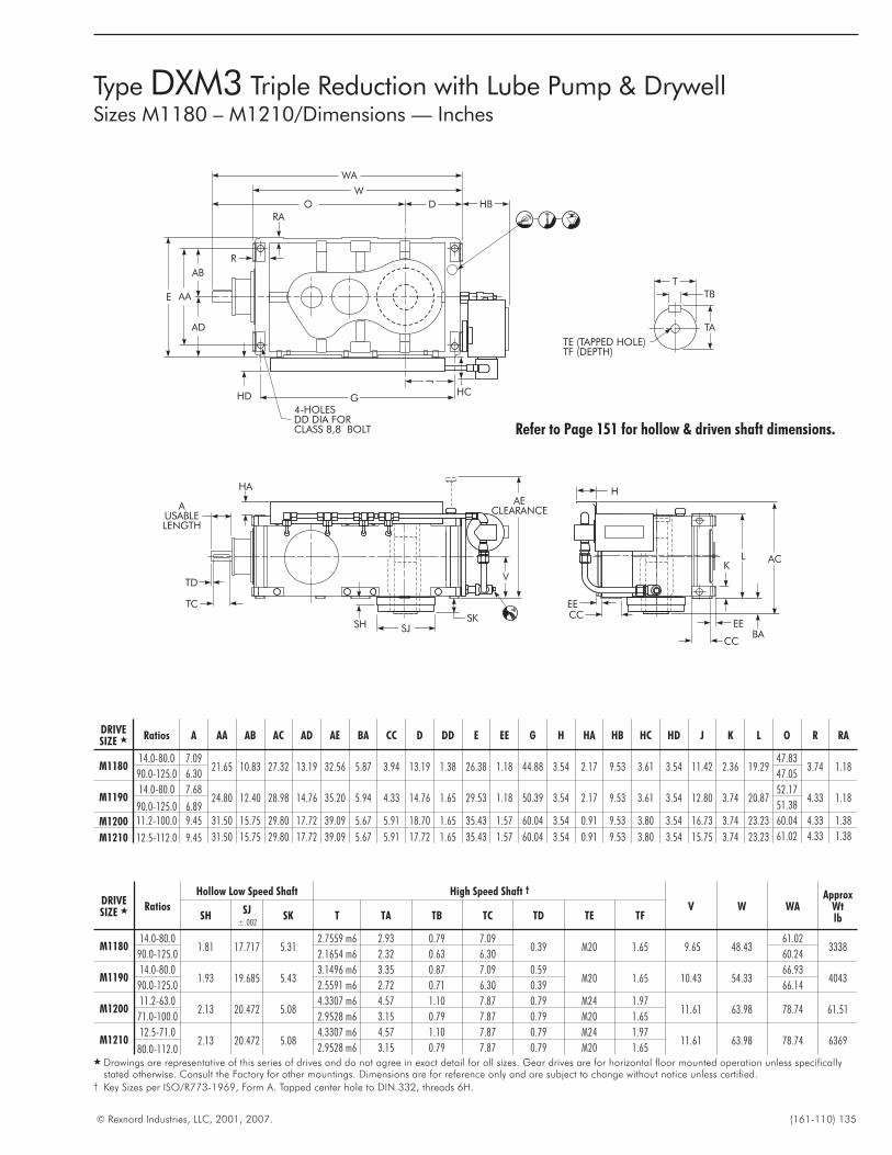
© Rexnord Industries, LLC, 2001, 2007. (161-110) 135
Type DXM3 Triple Reduction with Lube Pump & DrywellSizes M1180 – M1210/Dimensions — Inches
AECLEARANCE
V
SKSH SJ
TC
TD
AUSABLELENGTH
HA
T
TB
TA
TE (TAPPED HOLE)TF (DEPTH)
4-HOLESDD DIA FORCLASS 8,8 BOLT
W
O D
WA
W
O D HB
HC
J
GHD
AD
AB
AAE
R
RA
M
MQ
Q
L
EE
H
L AC
BA
K
EE
CC
CCEE
Refer to Page 151 for hollow & driven shaft dimensions.
DRIVESIZE � Ratios A AA AB AC AD AE BA CC D DD E EE G H HA HB HC HD J K L O R RA
M118014.0-80.0 7.09
21.65 10.83 27.32 13.19 32.56 5.87 3.94 13.19 1.38 26.38 1.18 44.88 3.54 2.17 9.53 3.61 3.54 11.42 2.36 19.2947.83
3.74 1.1890.0-125.0 6.30 47.05
M119014.0-80.0 7.68
24.80 12.40 28.98 14.76 35.20 5.94 4.33 14.76 1.65 29.53 1.18 50.39 3.54 2.17 9.53 3.61 3.54 12.80 3.74 20.8752.17
4.33 1.1890.0-125.0 6.89 51.38
M1200 11.2-100.0 9.45 31.50 15.75 29.80 17.72 39.09 5.67 5.91 18.70 1.65 35.43 1.57 60.04 3.54 0.91 9.53 3.80 3.54 16.73 3.74 23.23 60.04 4.33 1.38
M1210 12.5-112.0 9.45 31.50 15.75 29.80 17.72 39.09 5.67 5.91 17.72 1.65 35.43 1.57 60.04 3.54 0.91 9.53 3.80 3.54 15.75 3.74 23.23 61.02 4.33 1.38
DRIVESIZE � Ratios
Hollow Low Speed Shaft High Speed Shaft †
V W WAApprox
WtlbSH
SJ±.002
SK T TA TB TC TD TE TF
M118014.0-80.0
1.81 17.717 5.312.7559 m6 2.93 0.79 7.09
0.39 M20 1.65 9.65 48.4361.02
333890.0-125.0 2.1654 m6 2.32 0.63 6.30 60.24
M119014.0-80.0
1.93 19.685 5.433.1496 m6 3.35 0.87 7.09 0.59
M20 1.65 10.43 54.3366.93
404390.0-125.0 2.5591 m6 2.72 0.71 6.30 0.39 66.14
M120011.2-63.0
2.13 20.472 5.084.3307 m6 4.57 1.10 7.87 0.79 M24 1.97
11.61 63.98 78.74 61.5171.0-100.0 2.9528 m6 3.15 0.79 7.87 0.79 M20 1.65
M121012.5-71.0
2.13 20.472 5.084.3307 m6 4.57 1.10 7.87 0.79 M24 1.97
11.61 63.98 78.74 636980.0-112.0 2.9528 m6 3.15 0.79 7.87 0.79 M20 1.65
� Drawings are representative of this series of drives and do not agree in exact detail for all sizes. Gear drives are for horizontal floor mounted operation unless specificallystated otherwise. Consult the Factory for other mountings. Dimensions are for reference only and are subject to change without notice unless certified.
† Key Sizes per ISO/R773-1969, Form A. Tapped center hole to DIN 332, threads 6H.
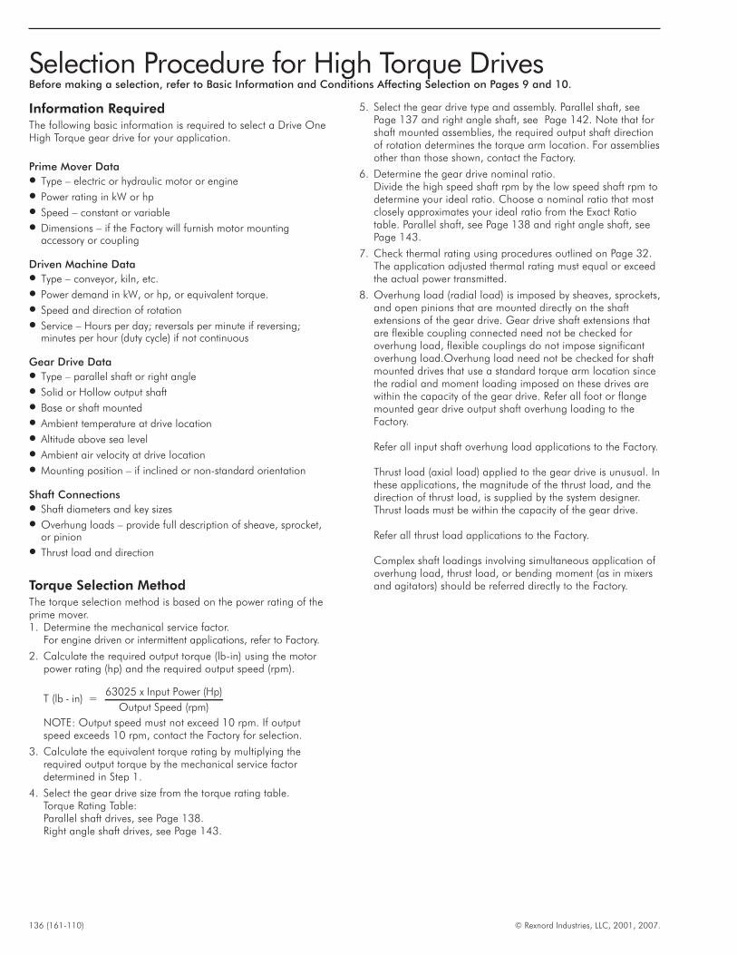
Information RequiredThe following basic information is required to select a Drive OneHigh Torque gear drive for your application.
Prime Mover Data� Type – electric or hydraulic motor or engine
� Power rating in kW or hp
� Speed – constant or variable
� Dimensions – if the Factory will furnish motor mountingaccessory or coupling
Driven Machine Data� Type – conveyor, kiln, etc.
� Power demand in kW, or hp, or equivalent torque.
� Speed and direction of rotation
� Service – Hours per day; reversals per minute if reversing;minutes per hour (duty cycle) if not continuous
Gear Drive Data� Type – parallel shaft or right angle
� Solid or Hollow output shaft
� Base or shaft mounted
� Ambient temperature at drive location
� Altitude above sea level
� Ambient air velocity at drive location
� Mounting position – if inclined or non-standard orientation
Shaft Connections� Shaft diameters and key sizes
� Overhung loads – provide full description of sheave, sprocket,or pinion
� Thrust load and direction
Torque Selection MethodThe torque selection method is based on the power rating of theprime mover.1. Determine the mechanical service factor.
For engine driven or intermittent applications, refer to Factory.
2. Calculate the required output torque (lb-in) using the motorpower rating (hp) and the required output speed (rpm).
T (lb - in) =63025 x Input Power (Hp)
Output Speed (rpm)
NOTE: Output speed must not exceed 10 rpm. If outputspeed exceeds 10 rpm, contact the Factory for selection.
3. Calculate the equivalent torque rating by multiplying therequired output torque by the mechanical service factordetermined in Step 1.
4. Select the gear drive size from the torque rating table.Torque Rating Table:Parallel shaft drives, see Page 138.Right angle shaft drives, see Page 143.
5. Select the gear drive type and assembly. Parallel shaft, seePage 137 and right angle shaft, see Page 142. Note that forshaft mounted assemblies, the required output shaft directionof rotation determines the torque arm location. For assembliesother than those shown, contact the Factory.
6. Determine the gear drive nominal ratio.Divide the high speed shaft rpm by the low speed shaft rpm todetermine your ideal ratio. Choose a nominal ratio that mostclosely approximates your ideal ratio from the Exact Ratiotable. Parallel shaft, see Page 138 and right angle shaft, seePage 143.
7. Check thermal rating using procedures outlined on Page 32.The application adjusted thermal rating must equal or exceedthe actual power transmitted.
8. Overhung load (radial load) is imposed by sheaves, sprockets,and open pinions that are mounted directly on the shaftextensions of the gear drive. Gear drive shaft extensions thatare flexible coupling connected need not be checked foroverhung load, flexible couplings do not impose significantoverhung load.Overhung load need not be checked for shaftmounted drives that use a standard torque arm location sincethe radial and moment loading imposed on these drives arewithin the capacity of the gear drive. Refer all foot or flangemounted gear drive output shaft overhung loading to theFactory.
Refer all input shaft overhung load applications to the Factory.
Thrust load (axial load) applied to the gear drive is unusual. Inthese applications, the magnitude of the thrust load, and thedirection of thrust load, is supplied by the system designer.Thrust loads must be within the capacity of the gear drive.
Refer all thrust load applications to the Factory.
Complex shaft loadings involving simultaneous application ofoverhung load, thrust load, or bending moment (as in mixersand agitators) should be referred directly to the Factory.
136 (161-110) © Rexnord Industries, LLC, 2001, 2007.
Selection Procedure for High Torque DrivesBefore making a selection, refer to Basic Information and Conditions Affecting Selection on Pages 9 and 10.
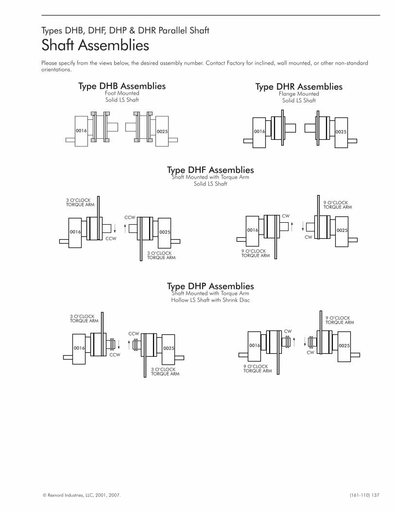
© Rexnord Industries, LLC, 2001, 2007. (161-110) 137
Types DHB, DHF, DHP & DHR Parallel Shaft
Shaft AssembliesPlease specify from the views below, the desired assembly number. Contact Factory for inclined, wall mounted, or other non-standardorientations.
Type DHB AssembliesFoot MountedSolid LS Shaft
Type DHP AssembliesShaft Mounted with Torque ArmHollow LS Shaft with Shrink Disc
Type DHR AssembliesFlange Mounted
Solid LS Shaft
0016 0025
0016 0025
CCW
CCW
3 O’CLOCKTORQUE ARM
3 O’CLOCKTORQUE ARM
00250016
0016 0025
CW
CW
9 O’CLOCKTORQUE ARM
9 O’CLOCKTORQUE ARM
Type DHF AssembliesShaft Mounted with Torque Arm
Solid LS Shaft
0016 0025
CCW
CCW
3 O’CLOCKTORQUE ARM
3 O’CLOCKTORQUE ARM
0016 0025
CW
CW
9 O’CLOCKTORQUE ARM
9 O’CLOCKTORQUE ARM
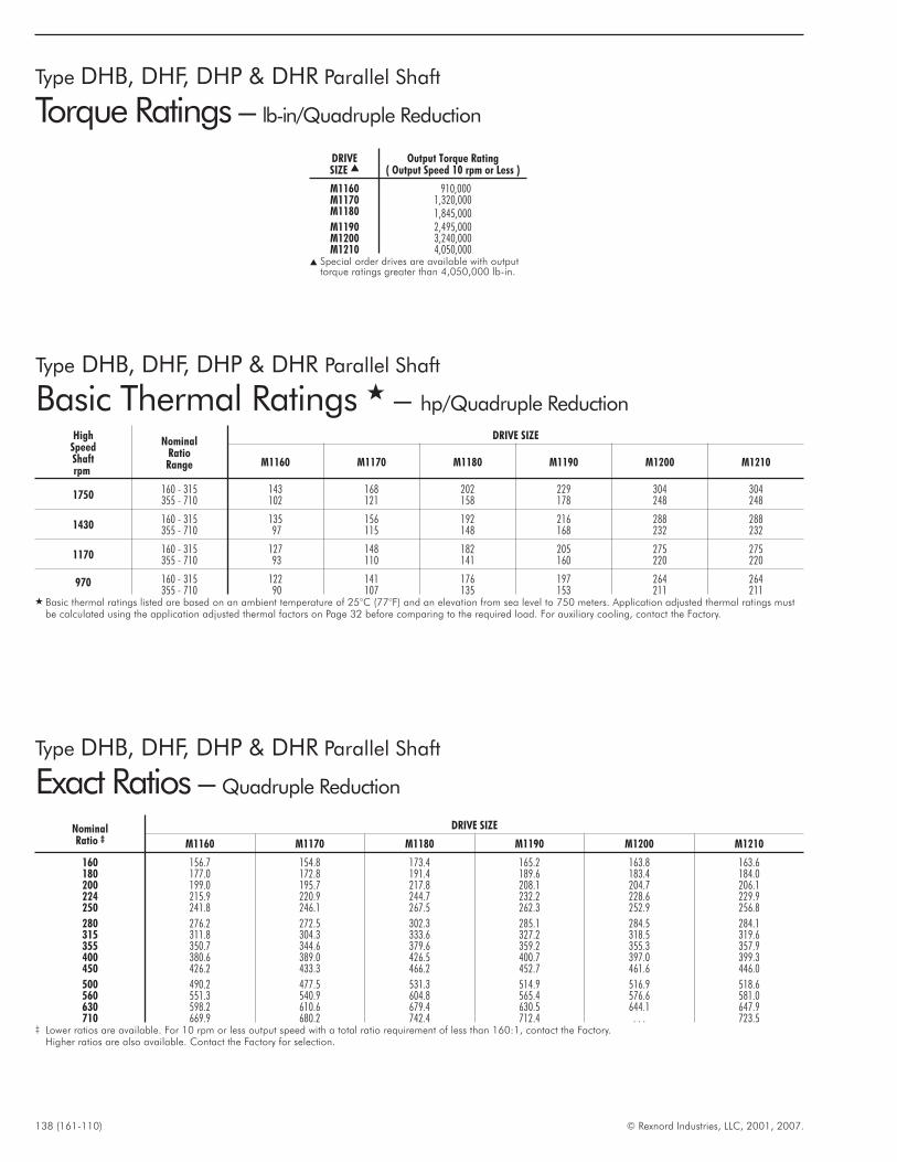
138 (161-110) © Rexnord Industries, LLC, 2001, 2007.
Type DHB, DHF, DHP & DHR Parallel Shaft
Torque Ratings – lb-in/Quadruple Reduction
Type DHB, DHF, DHP & DHR Parallel Shaft
Basic Thermal Ratings � – hp/Quadruple Reduction
Type DHB, DHF, DHP & DHR Parallel Shaft
Exact Ratios – Quadruple Reduction
NominalRatio ‡
DRIVE SIZE
M1160 M1170 M1180 M1190 M1200 M1210
160 156.7 154.8 173.4 165.2 163.8 163.6180 177.0 172.8 191.4 189.6 183.4 184.0200 199.0 195.7 217.8 208.1 204.7 206.1224 215.9 220.9 244.7 232.2 228.6 229.9250 241.8 246.1 267.5 262.3 252.9 256.8
280 276.2 272.5 302.3 285.1 284.5 284.1315 311.8 304.3 333.6 327.2 318.5 319.6355 350.7 344.6 379.6 359.2 355.3 357.9400 380.6 389.0 426.5 400.7 397.0 399.3450 426.2 433.3 466.2 452.7 461.6 446.0
500 490.2 477.5 531.3 514.9 516.9 518.6560 551.3 540.9 604.8 565.4 576.6 581.0630 598.2 610.6 679.4 630.5 644.1 647.9710 669.9 680.2 742.4 712.4 . . . 723.5
‡ Lower ratios are available. For 10 rpm or less output speed with a total ratio requirement of less than 160:1, contact the Factory.Higher ratios are also available. Contact the Factory for selection.
HighSpeedShaftrpm
NominalRatioRange
DRIVE SIZE
M1160 M1170 M1180 M1190 M1200 M1210
1750 160 - 315 143 168 202 229 304 304355 - 710 102 121 158 178 248 248
1430 160 - 315 135 156 192 216 288 288355 - 710 97 115 148 168 232 232
1170 160 - 315 127 148 182 205 275 275355 - 710 93 110 141 160 220 220
970 160 - 315 122 141 176 197 264 264355 - 710 90 107 135 153 211 211
� Basic thermal ratings listed are based on an ambient temperature of 25°C (77°F) and an elevation from sea level to 750 meters. Application adjusted thermal ratings mustbe calculated using the application adjusted thermal factors on Page 32 before comparing to the required load. For auxiliary cooling, contact the Factory.
DRIVESIZE �
Output Torque Rating( Output Speed 10 rpm or Less )
M1160 910,000M1170 1,320,000M1180 1,845,000M1190 2,495,000M1200 3,240,000M1210 4,050,000
� Special order drives are available with outputtorque ratings greater than 4,050,000 lb-in.
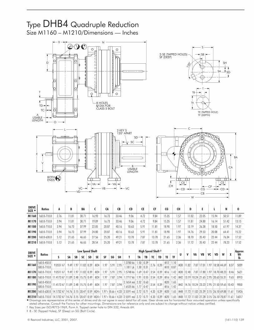
© Rexnord Industries, LLC, 2001, 2007. (161-110) 139
DRIVESIZE � Ratios A B BA C CA CB CD CE CF CG CH D E L N O
M1160 160.0-710.0 2.76 11.81 30.71 16.93 16.73 33.46 9.06 4.72 9.84 15.35 1.57 11.02 22.05 15.94 50.51 11.89
M1170 160.0-710.0 3.94 11.81 30.71 19.09 16.73 33.46 9.06 4.72 9.84 15.35 1.57 11.81 24.80 16.14 51.42 13.15
M1180 160.0-710.0 3.94 16.73 37.99 22.05 20.87 40.16 10.63 5.91 11.81 18.90 1.97 13.19 26.38 18.50 61.97 14.37
M1190 160.0-710.0 3.94 16.73 37.99 24.80 20.87 40.16 10.63 5.91 11.81 18.90 1.97 14.76 29.53 20.08 64.41 15.22
M1200 160.0-630.0 5.12 21.65 46.65 27.56 25.20 49.21 13.78 7.87 13.78 21.65 2.36 18.70 35.43 22.44 76.34 17.52
M1210 160.0-710.0 5.12 21.65 46.65 28.54 25.20 49.21 13.78 7.87 13.78 21.65 2.36 17.72 35.43 22.44 78.23 17.52
DRIVESIZE � Ratios
Low Speed Shaft High Speed Shaft †
U V VA VB VC VD W XApprox
WtlbS SA SB SC SD SE SF SG SH T TA TB TC TD TE TF
M1160160.0-450.0
9.0551 h7 9.49 1.97 11.02 0.39 M24 1.97 5.91 2.951.3780 k6 1.50 0.39
2.76 0.20M12 1.10
M30 11.02 7.87 17.01 1.97 18.58 44.69 8.37 5039500.0-710.0 1.1811 j6 1.30 0.31 M10 0.87
M1170 160.0-710.0 9.0511 h7 9.49 1.97 11.02 0.39 M24 1.97 5.91 2.95 1.5748 k6 1.69 0.47 3.54 0.39 M16 1.42 M30 12.40 7.87 17.80 1.97 18.70 48.23 8.46 5621
M1180 160.0-710.0 11.4173 h7 11.89 2.48 15.75 0.49 M24 1.97 7.87 3.94 1.7717 k6 1.91 0.55 3.54 0.39 M16 1.42 M42 13.19 10.24 21.65 2.95 20.63 55.31 9.65 8913
M1190160.0-450.0
11.4173 h7 11.89 2.48 15.75 0.49 M24 1.97 7.87 3.942.1654 m6 2.32 0.63
3.54 0.39M20 1.65
M42 14.76 10.24 23.23 2.95 21.50 59.65 10.43 9850500.0-710.0 1.6535 k6 1.77 0.47 M16 1.42
M1200 160.0-630.0 14.1732 h7 14.76 3.15 20.47 0.59 M24 ‡ 1.97 ‡ 8.66 ‡ 4.33 2.5591 m6 2.72 0.71 4.33 0.39 M20 1.65 M48 17.72 11.02 25.39 3.15 26.10 69.88 11.61 15426
M1210 160.0-710.0 14.1732 h7 14.76 3.15 20.47 0.59 M24 ‡ 1.97 ‡ 8.66 ‡ 4.33 2.5591 m6 2.72 0.71 4.33 0.39 M20 1.65 M48 17.72 11.02 27.28 3.15 26.10 70.87 11.61 16017� Drawings are representative of this series of drives and do not agree in exact detail for all sizes. Gear drives are for horizontal floor mounted operation unless specifically
stated otherwise. Consult the Factory for other mountings. Dimensions are for reference only and are subject to change without notice unless certified.† Key Sizes per ISO/R773-1969, Form A. Tapped center hole to DIN 332, threads 6H.‡ 8 - SE (Tapped Holes), SF (Deep) on SG (Bolt Circle).
BA
C
W
CA
CHCE CE
CFCDCD
CB
CG
TE (TAPPED HOLE)TF (DEPTH)
TA
TB
T
2-SE (TAPPED HOLES)SF (DEEP)
SB
S
120°
SA
SH
SG
BUSABLELENGTH
SD
SC
2 KEY S120° APART
BOTHENDS
VAVA
VDVB VCVC
V
E
L
N
AUSABLELENGTH
T
TD
TC
O
X
D
8 HOLESDIA FOR
CLASS 5 BOLTU
Type DHB4 Quadruple ReductionSize M1160 – M1210/Dimensions — Inches
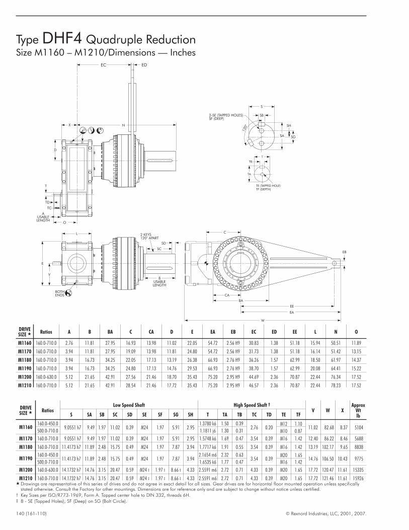
140 (161-110) © Rexnord Industries, LLC, 2001, 2007.
Type DHF4 Quadruple ReductionSize M1160 – M1210/Dimensions — Inches
TE (TAPPED HOLE)TF (DEPTH)
TA
TB
T
2-SE (TAPPED HOLES)SF (DEEP)
SB
S
120°
SA
SH
SG
AUSABLELENGTH
T
TD
TC
O
X
D
EC ED
N
BUSABLELENGTH
SD
SC
2 KEYS120° APART
BOTHENDS
V
E
L C
W
EB
EE
EA
CA
BA
DRIVESIZE � Ratios A B BA C CA D E EA EB EC ED EE L N O
M1160 160.0-710.0 2.76 11.81 27.95 16.93 13.98 11.02 22.05 54.72 2.56 H9 30.83 1.38 51.18 15.94 50.51 11.89
M1170 160.0-710.0 3.94 11.81 27.95 19.09 13.98 11.81 24.80 54.72 2.56 H9 31.73 1.38 51.18 16.14 51.42 13.15
M1180 160.0-710.0 3.94 16.73 34.25 22.05 17.13 13.19 26.38 66.93 2.76 H9 36.26 1.57 62.99 18.50 61.97 14.37
M1190 160.0-710.0 3.94 16.73 34.25 24.80 17.13 14.76 29.53 66.93 2.76 H9 38.70 1.57 62.99 20.08 64.41 15.22
M1200 160.0-630.0 5.12 21.65 42.91 27.56 21.46 18.70 35.43 75.20 2.95 H9 44.69 2.36 70.87 22.44 76.34 17.52
M1210 160.0-710.0 5.12 21.65 42.91 28.54 21.46 17.72 35.43 75.20 2.95 H9 46.57 2.36 70.87 22.44 78.23 17.52
DRIVESIZE � Ratios
Low Speed Shaft High Speed Shaft †
V W XApprox
WtlbS SA SB SC SD SE SF SG SH T TA TB TC TD TE TF
M1160160.0-450.0
9.0551 h7 9.49 1.97 11.02 0.39 M24 1.97 5.91 2.951.3780 k6 1.50 0.39
2.76 0.20M12 1.10
11.02 82.68 8.37 5104500.0-710.0 1.1811 j6 1.30 0.31 M10 0.87
M1170 160.0-710.0 9.0551 h7 9.49 1.97 11.02 0.39 M24 1.97 5.91 2.95 1.5748 k6 1.69 0.47 3.54 0.39 M16 1.42 12.40 86.22 8.46 5688
M1180 160.0-710.0 11.4173 h7 11.89 2.48 15.75 0.49 M24 1.97 7.87 3.94 1.7717 k6 1.91 0.55 3.54 0.39 M16 1.42 13.19 102.17 9.65 8838
M1190160.0-450.0
11.4173 h7 11.89 2.48 15.75 0.49 M24 1.97 7.87 3.942.1654 m6 2.32 0.63
3.54 0.39M20 1.65
14.76 106.50 10.43 9775500.0-710.0 1.6535 k6 1.77 0.47 M16 1.42
M1200 160.0-630.0 14.1732 h7 14.76 3.15 20.47 0.59 M24 ‡ 1.97 ‡ 8.66 ‡ 4.33 2.5591 m6 2.72 0.71 4.33 0.39 M20 1.65 17.72 120.47 11.61 15335
M1210 160.0-710.0 14.1732 h7 14.76 3.15 20.47 0.59 M24 ‡ 1.97 ‡ 8.66 ‡ 4.33 2.5591 m6 2.72 0.71 4.33 0.39 M20 1.65 17.72 121.46 11.61 15926� Drawings are representative of this series of drives and do not agree in exact detail for all sizes. Gear drives are for horizontal floor mounted operation unless specifically
stated otherwise. Consult the Factory for other mountings. Dimensions are for reference only and are subject to change without notice unless certified.† Key Sizes per ISO/R773-1969, Form A. Tapped center hole to DIN 332, threads 6H.‡ 8 - SE (Tapped Holes), SF (Deep) on SG (Bolt Circle).
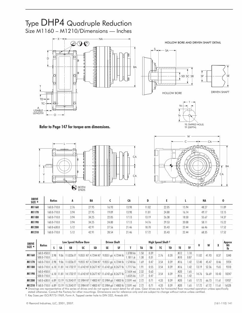
© Rexnord Industries, LLC, 2001, 2007. (161-110) 141
DRIVESIZE � Ratios A BA C CA D E L NA O
M1160 160.0-710.0 2.76 27.95 16.93 13.98 11.02 22.05 15.94 48.27 11.89
M1170 160.0-710.0 3.94 27.95 19.09 13.98 11.81 24.80 16.14 49.17 13.15
M1180 160.0-710.0 3.94 34.25 22.05 17.13 13.19 26.38 18.50 55.67 14.37
M1190 160.0-710.0 3.94 34.25 24.80 17.13 14.76 29.53 20.08 58.11 15.22
M1200 160.0-630.0 5.12 42.91 27.56 21.46 18.70 35.43 22.44 66.46 17.52
M1210 160.0-710.0 5.12 42.91 28.54 21.46 17.72 35.43 22.44 68.35 17.52
DRIVESIZE � Ratios
Low Speed Hollow Bore Driven Shaft High Speed Shaft †
V W XApprox
WtlbS SA SB SC SD SE SF T TA TB TC TD TE TF
M1160160.0-450.0
3.98 9.06 11.0236 f7 9.0551 H7 4.7244 H7 9.0551 g6 4.7244 f61.3780 k6 1.50 0.39
2.76 0.20M12 1.10
11.02 41.93 8.37 5340500.0-710.0 1.1811 j6 1.30 0.31 M10 0.87
M1170 160.0-710.0 3.98 9.06 11.0236 f7 9.0551 H7 4.7244 H7 9.0551 g6 4.7244 f6 1.5748 k6 1.69 0.47 3.54 0.39 M16 1.42 12.40 45.47 8.46 5924
M1180 160.0-710.0 6.10 11.81 14.1732 f7 11.6142 H7 8.2677 H7 11.6142 g6 8.2677 f6 1.7717 k6 1.91 0.55 3.54 0.39 M16 1.42 13.19 52.36 9.65 9310
M1190160.0-450.0
6.10 11.81 14.1732 f7 11.6142 H7 8.2677 H7 11.6142 g6 8.2677 f62.1654 m6 2.32 0.63
3.54 0.39M20 1.65
14.76 56.69 10.43 10247500.0-710.0 1.6535 k6 1.77 0.47 M16 1.42
M1200 160.0-630.0 6.89 13.19 15.3543 f7 12.5984 H7 7.4803 H7 12.5984 g6 7.4803 f6 2.5591 m6 2.72 0.71 4.33 0.39 M20 1.65 17.72 66.73 11.61 15937
M1210 160.0-710.0 6.89 13.19 15.3543 f7 12.5984 H7 7.4803 H7 12.5984 g6 7.4803 f6 2.5591 m6 2.72 0.71 4.33 0.39 M20 1.65 17.72 67.72 11.61 16528� Drawings are representative of this series of drives and do not agree in exact detail for all sizes. Gear drives are for horizontal floor mounted operation unless specifically
stated otherwise. Consult the Factory for other mountings. Dimensions are for reference only and are subject to change without notice unless certified.† Key Sizes per ISO/R773-1969, Form A. Tapped center hole to DIN 332, threads 6H.
Type DHP4 Quadruple ReductionSize M1160 – M1210/Dimensions — Inches
TE (TAPPED HOLE)TF (DEPTH)
TA
TB
T
DRIVEN SHAFTHOLLOW BORE
SSA
HOLLOW BORE AND DRIVEN SHAFT DETAIL
SF SESBSCSD
CA
BA
CA
W
C
BOTHENDS
CA
CAV
E
L
BA
NA
AUSABLELENGTH
T
TD
TC
O
X
D
Refer to Page 147 for torque arm dimensions.
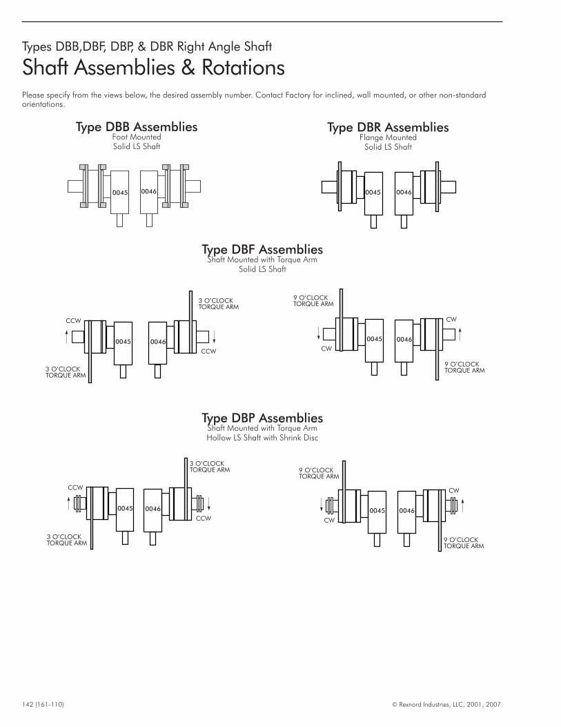
142 (161-110) © Rexnord Industries, LLC, 2001, 2007.
Types DBB,DBF, DBP, & DBR Right Angle Shaft
Shaft Assemblies & RotationsPlease specify from the views below, the desired assembly number. Contact Factory for inclined, wall mounted, or other non-standardorientations.
Type DBB AssembliesFoot MountedSolid LS Shaft
Type DBR AssembliesFlange Mounted
Solid LS Shaft
Type DBF AssembliesShaft Mounted with Torque Arm
Solid LS Shaft
0045 0046
0046
CW
9 O’CLOCKTORQUE ARM
0045
CW
9 O’CLOCKTORQUE ARM
0046
CCW
3 O’CLOCKTORQUE ARM
0045
CCW
3 O’CLOCKTORQUE ARM
00460045
Type DBP AssembliesShaft Mounted with Torque ArmHollow LS Shaft with Shrink Disc
0046
CCW
3 O’CLOCKTORQUE ARM
0045
CCW
3 O’CLOCKTORQUE ARM
0046
CW
9 O’CLOCKTORQUE ARM
0045
CW
9 O’CLOCKTORQUE ARM
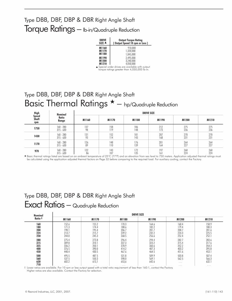
© Rexnord Industries, LLC, 2001, 2007. (161-110) 143
Type DBB, DBF, DBP & DBR Right Angle Shaft
Torque Ratings – lb-in/Quadruple Reduction
Type DBB, DBF, DBP & DBR Right Angle Shaft
Basic Thermal Ratings � – hp/Quadruple Reduction
Type DBB, DBF, DBP & DBR Right Angle Shaft
Exact Ratios – Quadruple Reduction
HighSpeedShaftrpm
NominalRatioRange
DRIVE SIZE
M1160 M1170 M1180 M1190 M1200 M1210
1750 160 - 280 137 158 186 212 275 275315 - 630 98 119 148 173 236 236
1430 160 - 280 131 152 181 207 270 270315 - 630 93 114 143 168 231 231
1170 160 - 280 126 148 176 201 264 264315 - 630 89 110 139 164 227 227
970 160 - 280 122 143 172 197 260 260315 - 630 86 107 135 161 224 224
� Basic thermal ratings listed are based on an ambient temperature of 25°C (77°F) and an elevation from sea level to 750 meters. Application adjusted thermal ratings mustbe calculated using the application adjusted thermal factors on Page 32 before comparing to the required load. For auxiliary cooling, contact the Factory.
NominalRatio ‡
DRIVE SIZE
M1160 M1170 M1180 M1190 M1200 M1210
160 152.6 155.2 170.3 164.6 160.4 158.9180 171.3 174.4 188.6 182.2 179.4 180.3200 190.1 195.4 206.7 201.7 200.7 201.6224 213.7 215.7 239.2 232.2 224.3 225.5250 244.0 245.3 268.5 256.6 252.4 252.1
280 275.4 273.8 296.4 294.4 282.7 283.6315 309.8 310.1 337.3 323.2 315.4 317.6355 336.2 350.1 378.9 360.6 352.2 354.3400 376.5 390.0 414.2 407.3 403.2 395.8450 440.4 430.5 467.6 464.5 451.6 453.1
500 495.5 487.5 531.8 509.9 503.8 507.4560 537.5 550.3 598.0 569.1 562.5 566.3630 602.2 613,1 653,6 642.6 . . . 632.1710 . . . . . . . . . . . . . . . . . .
‡ Lower ratios are available. For 10 rpm or less output speed with a total ratio requirement of less than 160:1, contact the Factory.Higher ratios are also available. Contact the Factory for selection.
DRIVESIZE �
Output Torque Rating( Output Speed 10 rpm or Less )
M1160 910,000M1170 1,320,000M1180 1,845,000M1190 2,495,000M1200 3,240,000M1210 4,050,000
� Special order drives are available with outputtorque ratings greater than 4,050,000 lb-in.
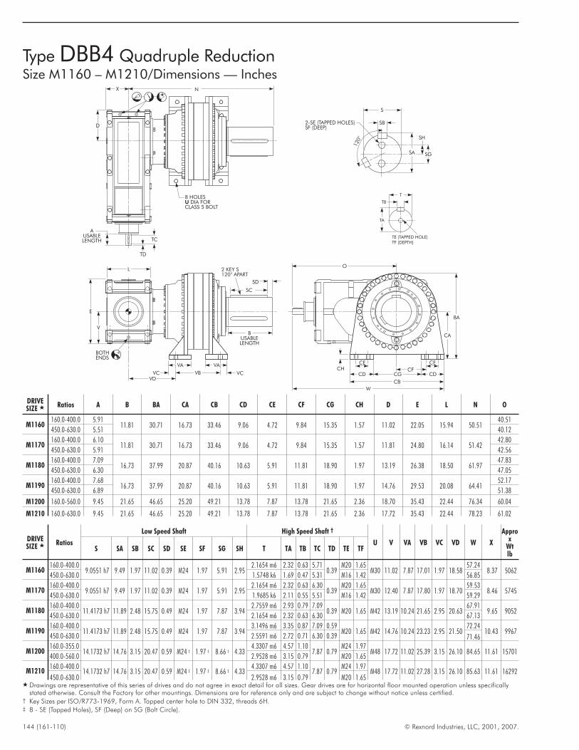
144 (161-110) © Rexnord Industries, LLC, 2001, 2007.
Type DBB4 Quadruple ReductionSize M1160 – M1210/Dimensions — Inches
BA
W
CA
CHCE CE
CFCDCD
CB
O
CG
TE (TAPPED HOLE)TF (DEPTH)
TA
TB
T
2-SE (TAPPED HOLES)SF (DEEP)
SB
S
120°
SA
SH
SG
BUSABLELENGTH
SD
SC
2 KEY S120° APART
BOTHENDS
VAVA
VDVB VCVC
V
E
L
AUSABLELENGTH TC
TD
N
D
X
8 HOLESDIA FOR
CLASS 5 BOLTU
DRIVESIZE � Ratios A B BA CA CB CD CE CF CG CH D E L N O
M1160160.0-400.0 5.91
11.81 30.71 16.73 33.46 9.06 4.72 9.84 15.35 1.57 11.02 22.05 15.94 50.5140.51
450.0-630.0 5.51 40.12
M1170160.0-400.0 6.10
11.81 30.71 16.73 33.46 9.06 4.72 9.84 15.35 1.57 11.81 24.80 16.14 51.4242.80
450.0-630.0 5.91 42.56
M1180160.0-400.0 7.09
16.73 37.99 20.87 40.16 10.63 5.91 11.81 18.90 1.97 13.19 26.38 18.50 61.9747.83
450.0-630.0 6.30 47.05
M1190160.0-400.0 7.68
16.73 37.99 20.87 40.16 10.63 5.91 11.81 18.90 1.97 14.76 29.53 20.08 64.4152.17
450.0-630.0 6.89 51.38
M1200 160.0-560.0 9.45 21.65 46.65 25.20 49.21 13.78 7.87 13.78 21.65 2.36 18.70 35.43 22.44 76.34 60.04
M1210 160.0-630.0 9.45 21.65 46.65 25.20 49.21 13.78 7.87 13.78 21.65 2.36 17.72 35.43 22.44 78.23 61.02
DRIVESIZE � Ratios
Low Speed Shaft High Speed Shaft †
U V VA VB VC VD W X
Approx
Wtlb
S SA SB SC SD SE SF SG SH T TA TB TC TD TE TF
M1160160.0-400.0
9.0551 h7 9.49 1.97 11.02 0.39 M24 1.97 5.91 2.952.1654 m6 2.32 0.63 5.71
0.39M20 1.65
M30 11.02 7.87 17.01 1.97 18.5857.24
8.37 5062450.0-630.0 1.5748 k6 1.69 0.47 5.31 M16 1.42 56.85
M1170160.0-400.0
9.0551 h7 9.49 1.97 11.02 0.39 M24 1.97 5.91 2.952.1654 m6 2.32 0.63 6.30
0.39M20 1.65
M30 12.40 7.87 17.80 1.97 18.7059.53
8.46 5745450.0-630.0 1.9685 k6 2.11 0.55 5.51 M16 1.42 59.29
M1180160.0-400.0
11.4173 h7 11.89 2.48 15.75 0.49 M24 1.97 7.87 3.942.7559 m6 2.93 0.79 7.09
0.39 M20 1.65 M42 13.19 10.24 21.65 2.95 20.6367.91
9.65 9052450.0-630.0 2.1654 m6 2.32 0.63 6.30 67.13
M1190160.0-400.0
11.4173 h7 11.89 2.48 15.75 0.49 M24 1.97 7.87 3.943.1496 m6 3.35 0.87 7.09 0.59
M20 1.65 M42 14.76 10.24 23.23 2.95 21.5072.24
10.43 9967450.0-630.0 2.5591 m6 2.72 0.71 6.30 0.39 71.46
M1200160.0-355.0
14.1732 h7 14.76 3.15 20.47 0.59 M24 ‡ 1.97 ‡ 8.66 ‡ 4.334.3307 m6 4.57 1.10
7.87 0.79M24 1.97
M48 17.72 11.02 25.39 3.15 26.10 84.65 11.61 15701400.0-560.0 2.9528 m6 3.15 0.79 M20 1.65
M1210160.0-400.0
14.1732 h7 14.76 3.15 20.47 0.59 M24 ‡ 1.97 ‡ 8.66 ‡ 4.334.3307 m6 4.57 1.10
7.87 0.79M24 1.97
M48 17.72 11.02 27.28 3.15 26.10 85.63 11.61 16292450.0-630.0 2.9528 m6 3.15 0.79 M20 1.65
� Drawings are representative of this series of drives and do not agree in exact detail for all sizes. Gear drives are for horizontal floor mounted operation unless specificallystated otherwise. Consult the Factory for other mountings. Dimensions are for reference only and are subject to change without notice unless certified.
† Key Sizes per ISO/R773-1969, Form A. Tapped center hole to DIN 332, threads 6H.‡ 8 - SE (Tapped Holes), SF (Deep) on SG (Bolt Circle).
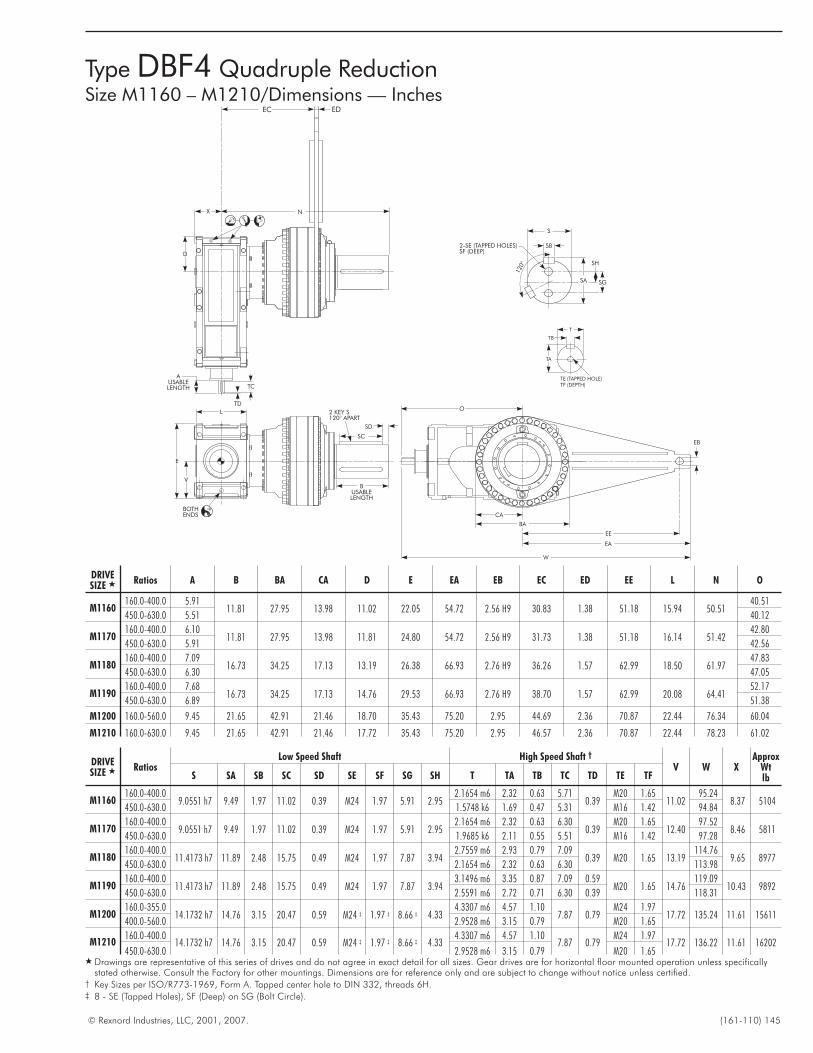
© Rexnord Industries, LLC, 2001, 2007. (161-110) 145
Type DBF4 Quadruple ReductionSize M1160 – M1210/Dimensions — Inches
TE (TAPPED HOLE)TF (DEPTH)
TA
TB
T
2-SE (TAPPED HOLES)SF (DEEP)
SB
S
120°
SA
SH
SG
BUSABLELENGTH
SD
SC
2 KEY S120° APART
BOTHENDS
V
E
L
AUSABLELENGTH TC
TD
D
X
EC ED
N
O
W
EB
EE
EA
CA
BA
DRIVESIZE � Ratios A B BA CA D E EA EB EC ED EE L N O
M1160160.0-400.0 5.91
11.81 27.95 13.98 11.02 22.05 54.72 2.56 H9 30.83 1.38 51.18 15.94 50.5140.51
450.0-630.0 5.51 40.12
M1170160.0-400.0 6.10
11.81 27.95 13.98 11.81 24.80 54.72 2.56 H9 31.73 1.38 51.18 16.14 51.4242.80
450.0-630.0 5.91 42.56
M1180160.0-400.0 7.09
16.73 34.25 17.13 13.19 26.38 66.93 2.76 H9 36.26 1.57 62.99 18.50 61.9747.83
450.0-630.0 6.30 47.05
M1190160.0-400.0 7.68
16.73 34.25 17.13 14.76 29.53 66.93 2.76 H9 38.70 1.57 62.99 20.08 64.4152.17
450.0-630.0 6.89 51.38
M1200 160.0-560.0 9.45 21.65 42.91 21.46 18.70 35.43 75.20 2.95 44.69 2.36 70.87 22.44 76.34 60.04
M1210 160.0-630.0 9.45 21.65 42.91 21.46 17.72 35.43 75.20 2.95 46.57 2.36 70.87 22.44 78.23 61.02
DRIVESIZE � Ratios
Low Speed Shaft High Speed Shaft †
V W XApprox
WtlbS SA SB SC SD SE SF SG SH T TA TB TC TD TE TF
M1160160.0-400.0
9.0551 h7 9.49 1.97 11.02 0.39 M24 1.97 5.91 2.952.1654 m6 2.32 0.63 5.71
0.39M20 1.65
11.0295.24
8.37 5104450.0-630.0 1.5748 k6 1.69 0.47 5.31 M16 1.42 94.84
M1170160.0-400.0
9.0551 h7 9.49 1.97 11.02 0.39 M24 1.97 5.91 2.952.1654 m6 2.32 0.63 6.30
0.39M20 1.65
12.4097.52
8.46 5811450.0-630.0 1.9685 k6 2.11 0.55 5.51 M16 1.42 97.28
M1180160.0-400.0
11.4173 h7 11.89 2.48 15.75 0.49 M24 1.97 7.87 3.942.7559 m6 2.93 0.79 7.09
0.39 M20 1.65 13.19114.76
9.65 8977450.0-630.0 2.1654 m6 2.32 0.63 6.30 113.98
M1190160.0-400.0
11.4173 h7 11.89 2.48 15.75 0.49 M24 1.97 7.87 3.943.1496 m6 3.35 0.87 7.09 0.59
M20 1.65 14.76119.09
10.43 9892450.0-630.0 2.5591 m6 2.72 0.71 6.30 0.39 118.31
M1200160.0-355.0
14.1732 h7 14.76 3.15 20.47 0.59 M24 ‡ 1.97 ‡ 8.66 ‡ 4.334.3307 m6 4.57 1.10
7.87 0.79M24 1.97
17.72 135.24 11.61 15611400.0-560.0 2.9528 m6 3.15 0.79 M20 1.65
M1210160.0-400.0
14.1732 h7 14.76 3.15 20.47 0.59 M24 ‡ 1.97 ‡ 8.66 ‡ 4.334.3307 m6 4.57 1.10
7.87 0.79M24 1.97
17.72 136.22 11.61 16202450.0-630.0 2.9528 m6 3.15 0.79 M20 1.65
� Drawings are representative of this series of drives and do not agree in exact detail for all sizes. Gear drives are for horizontal floor mounted operation unless specificallystated otherwise. Consult the Factory for other mountings. Dimensions are for reference only and are subject to change without notice unless certified.
† Key Sizes per ISO/R773-1969, Form A. Tapped center hole to DIN 332, threads 6H.‡ 8 - SE (Tapped Holes), SF (Deep) on SG (Bolt Circle).
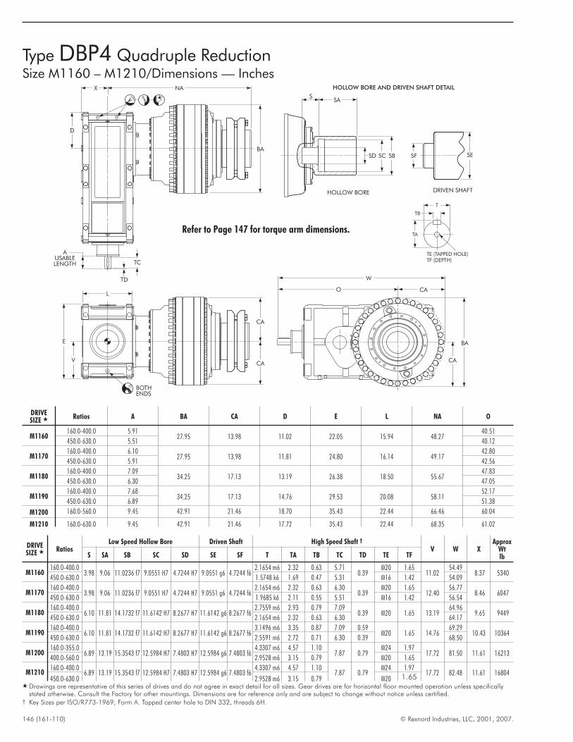
146 (161-110) © Rexnord Industries, LLC, 2001, 2007.
Type DBP4 Quadruple ReductionSize M1160 – M1210/Dimensions — Inches
TE (TAPPED HOLE)TF (DEPTH)
TA
TB
T
DRIVEN SHAFTHOLLOW BORE
SSA
HOLLOW BORE AND DRIVEN SHAFT DETAIL
SF SESBSCSD
CA
BA
O CA
W
BOTHENDS
CA
CAV
E
L
X
AUSABLELENGTH TC
TD
BA
NA
D
Refer to Page 147 for torque arm dimensions.
DRIVESIZE � Ratios A BA CA D E L NA O
M1160160.0-400.0 5.91
27.95 13.98 11.02 22.05 15.94 48.2740.51
450.0-630.0 5.51 40.12
M1170160.0-400.0 6.10
27.95 13.98 11.81 24.80 16.14 49.1742.80
450.0-630.0 5.91 42.56
M1180160.0-400.0 7.09
34.25 17.13 13.19 26.38 18.50 55.6747.83
450.0-630.0 6.30 47.05
M1190160.0-400.0 7.68
34.25 17.13 14.76 29.53 20.08 58.1152.17
450.0-630.0 6.89 51.38
M1200 160.0-560.0 9.45 42.91 21.46 18.70 35.43 22.44 66.46 60.04
M1210 160.0-630.0 9.45 42.91 21.46 17.72 35.43 22.44 68.35 61.02
DRIVESIZE � Ratios
Low Speed Hollow Bore Driven Shaft High Speed Shaft †
V W XApprox
WtlbS SA SB SC SD SE SF T TA TB TC TD TE TF
M1160160.0-400.0
3.98 9.06 11.0236 f7 9.0551 H7 4.7244 H7 9.0551 g6 4.7244 f62.1654 m6 2.32 0.63 5.71
0.39M20 1.65
11.0254.49
8.37 5340450.0-630.0 1.5748 k6 1.69 0.47 5.31 M16 1.42 54.09
M1170160.0-400.0
3.98 9.06 11.0236 f7 9.0551 H7 4.7244 H7 9.0551 g6 4.7244 f62.1654 m6 2.32 0.63 6.30
0.39M20 1.65
12.4056.77
8.46 6047450.0-630.0 1.9685 k6 2.11 0.55 5.51 M16 1.42 56.54
M1180160.0-400.0
6.10 11.81 14.1732 f7 11.6142 H7 8.2677 H7 11.6142 g6 8.2677 f62.7559 m6 2.93 0.79 7.09
0.39 M20 1.65 13.1964.96
9.65 9449450.0-630.0 2.1654 m6 2.32 0.63 6.30 64.17
M1190160.0-400.0
6.10 11.81 14.1732 f7 11.6142 H7 8.2677 H7 11.6142 g6 8.2677 f63.1496 m6 3.35 0.87 7.09 0.59
M20 1.65 14.7669.29
10.43 10364450.0-630.0 2.5591 m6 2.72 0.71 6.30 0.39 68.50
M1200160.0-355.0
6.89 13.19 15.3543 f7 12.5984 H7 7.4803 H7 12.5984 g6 7.4803 f64.3307 m6 4.57 1.10
7.87 0.79M24 1.97
17.72 81.50 11.61 16213400.0-560.0 2.9528 m6 3.15 0.79 M20 1.65
M1210160.0-400.0
6.89 13.19 15.3543 f7 12.5984 H7 7.4803 H7 12.5984 g6 7.4803 f64.3307 m6 4.57 1.10
7.87 0.79M24 1.97
17.72 82.48 11.61 16804450.0-630.0 2.9528 m6 3.15 0.79 M20 1.65
� Drawings are representative of this series of drives and do not agree in exact detail for all sizes. Gear drives are for horizontal floor mounted operation unless specificallystated otherwise. Consult the Factory for other mountings. Dimensions are for reference only and are subject to change without notice unless certified.
† Key Sizes per ISO/R773-1969, Form A. Tapped center hole to DIN 332, threads 6H.
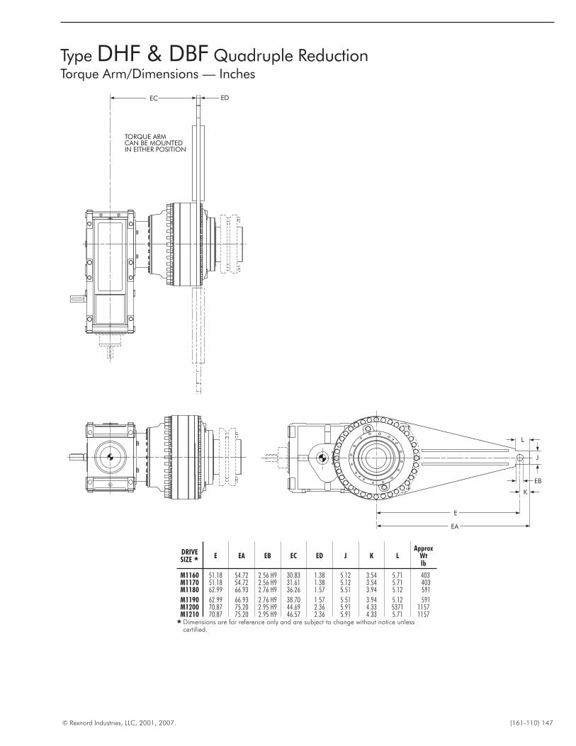
© Rexnord Industries, LLC, 2001, 2007. (161-110) 147
Type DHF & DBF Quadruple ReductionTorque Arm/Dimensions — Inches
TORQUE ARMCAN BE MOUNTEDIN EITHER POSITION
EC ED
E
EA
EB
K
J
L
DRIVESIZE � E EA EB EC ED J K L
ApproxWtlb
M1160 51.18 54.72 2.56 H9 30.83 1.38 5.12 3.54 5.71 403M1170 51.18 54.72 2.56 H9 31.61 1.38 5.12 3.54 5.71 403M1180 62.99 66.93 2.76 H9 36.26 1.57 5.51 3.94 5.12 591
M1190 62.99 66.93 2.76 H9 38.70 1.57 5.51 3.94 5.12 591M1200 70.87 75.20 2.95 H9 44.69 2.36 5.91 4.33 5371 1157M1210 70.87 75.20 2.95 H9 46.57 2.36 5.91 4.33 5.71 1157
� Dimensions are for reference only and are subject to change without notice unlesscertified.
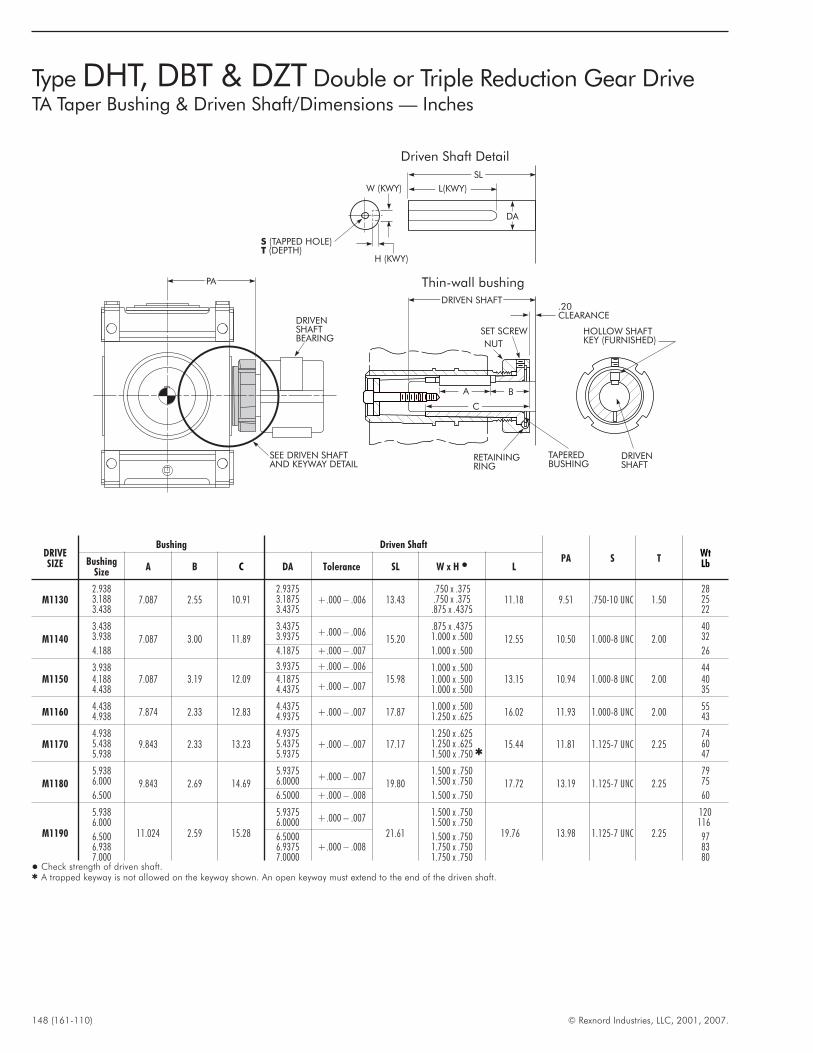
148 (161-110) © Rexnord Industries, LLC, 2001, 2007.
Type DHT, DBT & DZT Double or Triple Reduction Gear DriveTA Taper Bushing & Driven Shaft/Dimensions — Inches
SET SCREW
NUT
RETAININGRING
TAPEREDBUSHING
DRIVENSHAFT
HOLLOW SHAFTKEY (FURNISHED)
.20CLEARANCE
DRIVEN SHAFT
Thin-wall bushing
DRIVENSHAFTBEARING
SEE DRIVEN SHAFTAND KEYWAY DETAIL
A B
C
PA
ST
(TAPPED HOLE)(DEPTH)
W (KWY)
H (KWY)
SL
DA
L(KWY)
Driven Shaft Detail
DRIVESIZE
Bushing Driven Shaft
PA S TWtLbBushing
SizeA B C DA Tolerance SL W x H � L
M11302.938
7.087 2.55 10.912.9375
+.000 – .006 13.43.750 x .375
11.18 9.51 .750-10 UNC 1.5028
3.188 3.1875 .750 x .375 253.438 3.4375 .875 x .4375 22
M11403.438
7.087 3.00 11.893.4375
+.000 – .00615.20
.875 x .437512.55 10.50 1.000-8 UNC 2.00
403.938 3.9375 1.000 x .500 32
4.188 4.1875 +.000 – .007 1.000 x .500 26
M11503.938
7.087 3.19 12.093.9375 +.000 – .006
15.981.000 x .500
13.15 10.94 1.000-8 UNC 2.0044
4.188 4.1875+.000 – .007
1.000 x .500 404.438 4.4375 1.000 x .500 35
M11604.438
7.874 2.33 12.834.4375
+.000 – .007 17.871.000 x .500
16.02 11.93 1.000-8 UNC 2.0055
4.938 4.9375 1.250 x .625 43
M11704.938
9.843 2.33 13.234.9375
+.000 – .007 17.171.250 x .625
15.44 11.81 1.125-7 UNC 2.2574
5.438 5.4375 1.250 x .625 605.938 5.9375 1.500 x .750 � 47
M11805.938
9.843 2.69 14.695.9375
+.000 – .00719.80
1.500 x .75017.72 13.19 1.125-7 UNC 2.25
796.000 6.0000 1.500 x .750 75
6.500 6.5000 +.000 – .008 1.500 x .750 60
M1190
5.938
11.024 2.59 15.28
5.9375+.000 – .007
21.61
1.500 x .750
19.76 13.98 1.125-7 UNC 2.25
1206.000 6.0000 1.500 x .750 116
6.500 6.5000+.000 – .008
1.500 x .750 976.938 6.9375 1.750 x .750 837.000 7.0000 1.750 x .750 80
� Check strength of driven shaft.� A trapped keyway is not allowed on the keyway shown. An open keyway must extend to the end of the driven shaft.
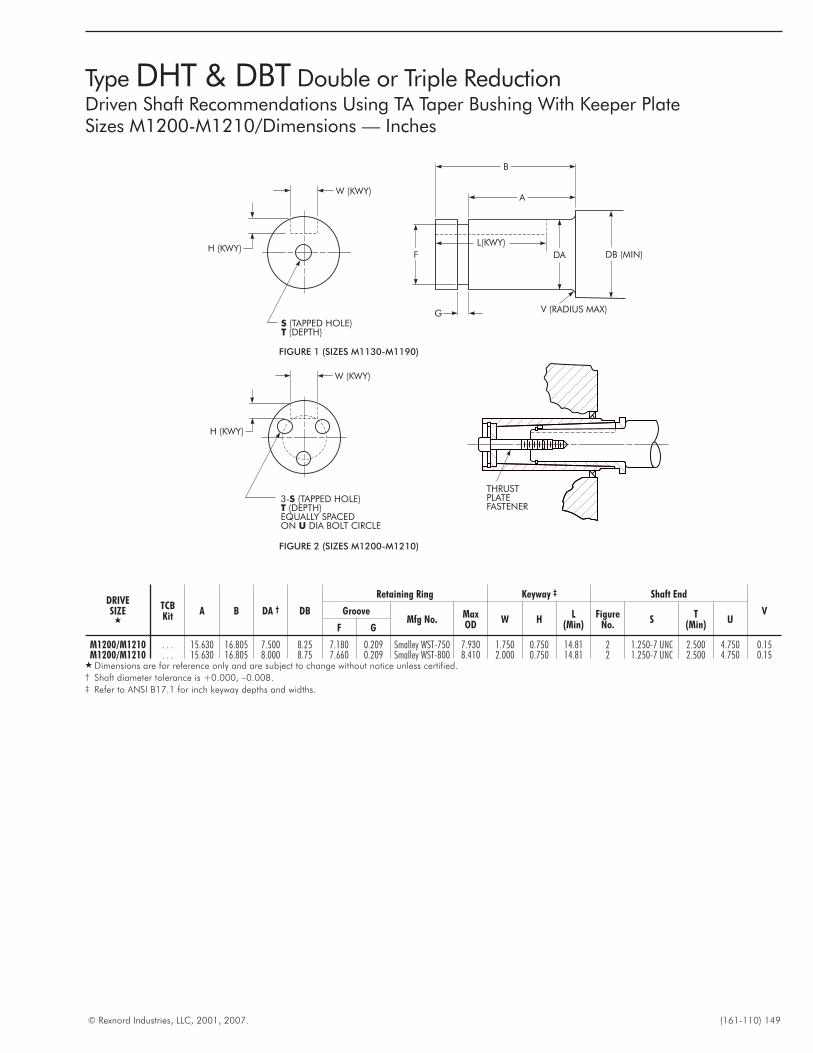
© Rexnord Industries, LLC, 2001, 2007. (161-110) 149
Type DHT & DBT Double or Triple ReductionDriven Shaft Recommendations Using TA Taper Bushing With Keeper PlateSizes M1200-M1210/Dimensions — Inches
ST
(TAPPED HOLE)(DEPTH)
W (KWY)
H (KWY)
FIGURE 1 (SIZES M1130-M1190)
G V (RADIUS MAX)
B
A
DB (MIN)DA
L(KWY)
F
3- (TAPPED HOLE)(DEPTH)
EQUALLY SPACEDON DIA BOLT CIRCLE
ST
U
FIGURE 2 (SIZES M1200-M1210)
W (KWY)
H (KWY)
THRUSTPLATEFASTENER
DRIVESIZE
�
TCBKit
A B DA † DB
Retaining Ring Keyway ‡ Shaft End
VGrooveMfg No.
MaxOD
W HL
(Min)Figure
No.S
T(Min)
UF G
M1200/M1210 . . . 15.630 16.805 7.500 8.25 7.180 0.209 Smalley WST-750 7.930 1.750 0.750 14.81 2 1.250-7 UNC 2.500 4.750 0.15M1200/M1210 . . . 15.630 16.805 8.000 8.75 7.660 0.209 Smalley WST-800 8.410 2.000 0.750 14.81 2 1.250-7 UNC 2.500 4.750 0.15
� Dimensions are for reference only and are subject to change without notice unless certified.† Shaft diameter tolerance is +0.000, –0.008.‡ Refer to ANSI B17.1 for inch keyway depths and widths.
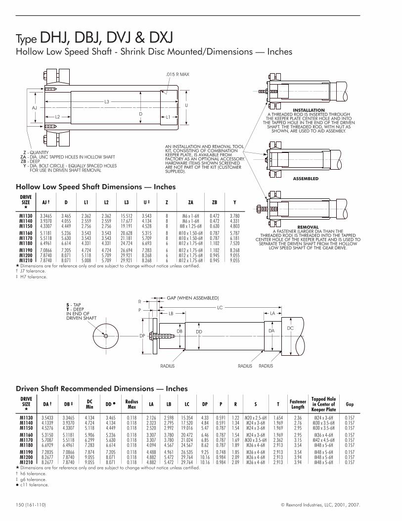
150 (161-110) © Rexnord Industries, LLC, 2001, 2007.
ASSEMBLED
REMOVALA FASTENER (LARGER DIA THAN THE
THREADED ROD) IS THREADED INTO THE TAPPEDCENTER HOLE OF THE KEEPER PLATE AND IS USED TO
SEPARATE THE DRIVEN SHAFT FROM THE HOLLOWLOW SPEED SHAFT OF THE GEAR DRIVE.
AN INSTALLATION AND REMOVAL TOOLKIT, CONSISTING OF COMBINATIONKEEPER PLATE, IS AVAILABLE FROMFACTORY AS AN OPTIONAL ACCESSORY.HARDWARE ITEMS SHOWN SCREENEDARE NOT PART OF THE KIT (CUSTOMERSUPPLIED).
INSTALLATIONA THREADED ROD IS INSERTED THROUGH
THE KEEPER PLATE CENTER HOLE AND INTOTHE TAPPED HOLE IN THE END OF THE DRIVEN
SHAFT. THE THREADED ROD, WITH NUT ASSHOWN, ARE USED TO AID ASSEMBLY.
Type DHJ, DBJ, DVJ & DXJHollow Low Speed Shaft - Shrink Disc Mounted/Dimensions — Inches
Hollow Low Speed Shaft Dimensions — Inches
DRIVESIZE
�AJ † D L1 L2 L3 U ‡ Z ZA ZB Y
M1130 3.3465 3.465 2.362 2.362 15.512 3.543 8 M6 x 1-6H 0.472 3.780M1140 3.9370 4.055 2.559 2.559 17.677 4.134 8 M6 x 1-6H 0.472 4.331M1150 4.3307 4.449 2.756 2.756 19.191 4.528 8 M8 x 1.25-6H 0.630 4.803
M1160 5.1181 5.236 3.543 3.543 20.628 5.315 8 M10 x 1.50-6H 0.787 5.787M1170 5.5118 5.630 3.543 3.543 21.181 5.709 8 M10 x 1.50-6H 0.787 6.181M1180 6.4961 6.614 4.331 4.331 24.724 6.693 6 M12 x 1.75-6H 1.102 7.520
M1190 7.0866 7.205 4.724 4.724 26.694 7.283 6 M12 x 1.75-6H 1.102 8.268M1200 7.8740 8.071 5.118 5.709 29.921 8.268 6 M12 x 1.75-6H 0.945 9.055M1210 7.8740 8.071 5.008 5.709 29.921 8.268 6 M12 x 1.75-6H 0.945 9.055
� Dimensions are for reference only and are subject to change without notice unless certified.† J7 tolerance.‡ H7 tolerance.
P
RGAP (WHEN ASSEMBLED)
LB
DDDB
DP
LC
LA
DADC
RADIUSRADIUS RADIUS
ST
- TAP- DEEP
IN END OFDRIVEN SHAFT
Driven Shaft Recommended Dimensions — Inches
DRIVESIZE
�DA † DB ‡ DC
MinDD �
RadiusMax
LA LB LC DP P R S TFastenerLength
Tapped Holein Center ofKeeper Plate
Gap
M1130 3.5433 3.3465 4.134 3.465 0.118 2.126 2.598 15.354 4.33 0.591 1.22 M20 x 2.5-6H 1.654 2.36 M24 x 3-6H 0.157M1140 4.1339 3.9370 4.724 4.134 0.118 2.323 2.795 17.520 4.84 0.591 1.34 M24 x 3-6H 1.969 2.76 M30 x 3.5-6H 0.157M1150 4.5276 4.3307 5.118 4.449 0.118 2.520 2.992 19.016 5.47 0.787 1.54 M24 x 3-6H 1.969 2.95 M30 x 3.5-6H 0.157
M1160 5.3150 5.1181 5.906 5.236 0.118 3.307 3.780 20.472 6.46 0.787 1.54 M24 x 3-6H 1.969 2.95 M36 x 4-6H 0.157M1170 5.7087 5.5118 6.299 5.630 0.118 3.307 3.780 21.024 6.85 0.787 1.69 M30 x 3.5-6H 2.362 3.15 M42 x 4.5-6H 0.157M1180 6.6929 6.4961 7.283 6.614 0.118 4.094 4.567 24.567 8.62 0.787 1.89 M36 x 4-6H 2.913 3.54 M48 x 5-6H 0.157
M1190 7.2835 7.0866 7.874 7.205 0.118 4.488 4.961 26.535 9.25 0.748 1.85 M36 x 4-6H 2.913 3.54 M48 x 5-6H 0.157M1200 8.2677 7.8740 9.055 8.071 0.118 4.882 5.472 29.764 10.16 0.984 2.09 M36 x 4-6H 2.913 3.94 M48 x 5-6H 0.157M1210 8.2677 7.8740 9.055 8.071 0.118 4.882 5.472 29.764 10.16 0.984 2.09 M36 x 4-6H 2.913 3.94 M48 x 5-6H 0.157
� Dimensions are for reference only and are subject to change without notice unless certified.† h6 tolerance.‡ g6 tolerance.� c11 tolerance.
L2
AJ
D
U
.015 R MAX
L1
L3
QUANTITY
DIA. UNC TAPPED HOLES IN HOLLOW SHAFT
DEEP
DIA. BOLT CIRCLE - EQUALLY SPACED HOLES
FOR USE IN DRIVEN SHAFT REMOVAL
ZZAZBY
----
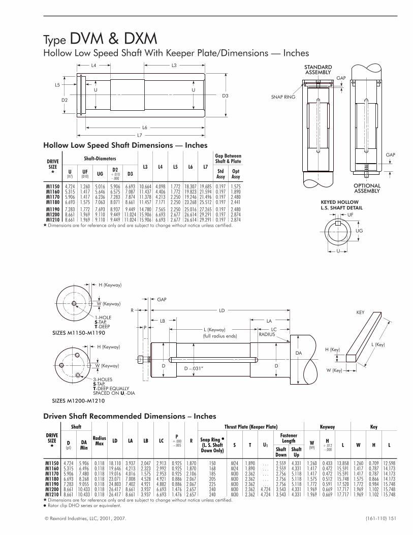
© Rexnord Industries, LLC, 2001, 2007. (161-110) 151
Type DVM & DXMHollow Low Speed Shaft With Keeper Plate/Dimensions — Inches
D3UU
D2
L3
L6
L7
L4
L5
GAP
OPTIONALASSEMBLY
STANDARDASSEMBLY
GAP
SNAP RING
UG
U
UF
KEYED HOLLOWL.S. SHAFT DETAIL
H (Keyway)
W (Keyway)
1-HOLE-TAP,-DEEP
ST
W (Key)
H (Key)L (Key)
KEYLD
LB LA
LC
DD
DA
L (Keyway)RADIUS
D –.031”
R
P
GAP
(full radius ends)
SIZES M1200-M1210
H (Keyway)
W (Keyway)
3-HOLES-TAP,-DEEP EQUALLY
SPACED ON -DIA
ST
U1
SIZES M1150-M1190
Driven Shaft Recommended Dimensions – Inches
DRIVESIZE
�
Shaft
RadiusMax
LD LA LB LCP
+.000–.005
R
Thrust Plate (Keeper Plate) Keyway Key
D(g6)
DAMin
Snap Ring �
(L. S. ShaftDown Only)
S T U1
FastenerLength W
(N9)
H+.012–.000
L W H LShaftDown
ShaftUp
M1150 4.724 5.906 0.118 18.110 3.937 2.047 2.913 0.925 1.870 150 M24 1.890 . . . 2.559 4.331 1.260 0.433 13.858 1.260 0.709 12.598M1160 5.315 6.496 0.118 19.646 4.213 2.323 2.992 0.925 1.870 168 M24 1.890 . . . 2.559 4.331 1.417 0.472 15.591 1.417 0.787 14.173M1170 5.906 7.480 0.118 19.016 4.016 1.575 2.953 0.925 2.106 185 M30 2.362 . . . 2.756 5.118 1.417 0.472 15.591 1.417 0.787 14.173M1180 6.693 8.268 0.118 23.071 7.008 4.528 4.921 0.886 2.067 205 M30 2.362 . . . 2.756 5.118 1.575 0.512 15.748 1.575 0.866 14.173M1190 7.283 9.055 0.118 24.803 7.402 4.921 4.882 0.886 2.067 225 M30 2.362 . . . 2.756 5.118 1.772 0.591 17.520 1.772 0.984 15.748M1200 8.661 10.433 0.118 26.417 8.661 3.937 6.693 1.476 2.657 240 M30 2.362 4.724 3.543 4.331 1.969 0.669 17.717 1.969 1.102 15.748M1210 8.661 10.433 0.118 26.417 8.661 3.937 6.693 1.476 2.657 240 M30 2.362 4.724 3.543 4.331 1.969 0.669 17.717 1.969 1.102 15.748
� Dimensions are for reference only and are subject to change without notice unless certified.� Rotor clip DHO series or equivalent.
Hollow Low Speed Shaft Dimensions — Inches
DRIVESIZE
�
Shaft-Diameters
L3 L4 L5 L6 L7
Gap BetweenShaft & Plate
U(H7)
UF(D10)
UGD2
+.010–.000
D3StdAssy
OptAssy
M1150 4.724 1.260 5.016 5.906 6.693 10.664 4.098 1.772 18.307 19.685 0.197 1.575M1160 5.315 1.417 5.646 6.575 7.087 11.437 4.406 1.772 19.823 21.594 0.197 1.890M1170 5.906 1.417 6.236 7.283 7.874 11.378 4.213 2.250 19.246 21.496 0.197 2.480M1180 6.693 1.575 7.063 8.071 8.661 11.457 7.171 2.250 23.268 25.512 0.197 2.441
M1190 7.283 1.772 7.693 8.937 9.449 14.780 7.565 2.250 25.016 27.265 0.197 2.480M1200 8.661 1.969 9.110 9.449 11.024 15.906 6.693 2.677 26.614 29.291 0.197 2.874M1210 8.661 1.969 9.110 9.449 11.024 15.906 6.693 2.677 26.614 29.291 0.197 2.874
� Dimensions are for reference only and are subject to change without notice unless certified.
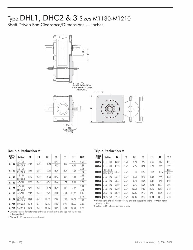
152 (161-110) © Rexnord Industries, LLC, 2001, 2007.
Type DHL1, DHC2 & 3 Sizes M1130-M1210Shaft Driven Fan Clearance/Dimensions — Inches
FA
FB
FDWITH SHAFT
COVER
FC
FE
FF
FGSHAFT EXTENSION
WITH SHAFT COVERREMOVED
Triple Reduction �
DRIVESIZE
Ratios FA FB FC FD FE FF FG ‡
M1130 31.5-140.0 17.09 0.60 6.28 9.57 3.66 6.86 1.21
M1140 31.5-140.0 18.98 0.59 7.26 10.98 4.29 7.29 0.92
M115031.5-90.0
21.54 0.67 7.85 11.57 4.85 8.161.84
100.0-140.0 1.56
M1160 31.5-140.0 22.72 0.67 8.54 13.46 6.02 7.99 1.33
M1170 31.5-140.0 25.51 0.67 8.74 14.69 6.81 8.98 1.93
M1180 31.5-140.0 27.09 0.67 9.76 15.39 8.94 12.76 2.05
M1190 31.5-140.0 30.20 0.67 10.63 17.83 10.16 15.85 2.12
M1200 25.0-112.0 36.10 0.67 12.36 19.17 8.98 12.20 2.13
M1210 28.0-125.0 36.10 0.67 12.36 19.17 10.94 14.17 2.13� Dimensions are for reference only and are subject to change without notice
unless certified.‡ Allows 0.12” clearance from shroud.
Double Reduction �
DRIVESIZE
Ratios FA FB FC FD FE FF FG ‡
M11306.3-16.0
17.09 0.60 6.2811.57
3.665.71 2.92
18.0-28.0 9.57 6.86 1.21
M11406.3-16.0
18.98 0.59 7.26 12.20 4.29 6.242.51
18.0-28.0 1.34
M11506.3-16.0
21.54 0.67 7.85 12.76 4.85 7.112.63
18.0-28.0 1.84
M1160 6.3-28.0 22.72 0.67 8.54 13.46 6.02 7.99 2.03
M11706.3-16.0
25.51 0.67 8.74 14.69 6.81 8.983.11
18.0-28.0 1.93
M1180 6.3-28.0 27.09 0.67 9.76 16.30 8.94 11.97 3.15
M11906.3-16.0
30.20 0.67 11.22 17.83 10.16 13.783.86
18.0-28.0 2.68
M1200 5.00-22.4 36.10 0.67 12.36 19.02 8.98 16.56 3.30
M1210 5.60-25.0 36.10 0.67 12.36 19.02 10.94 17.54 3.30� Dimensions are for reference only and are subject to change without notice
unless certified.‡ Allows 0.12” clearance from shroud.
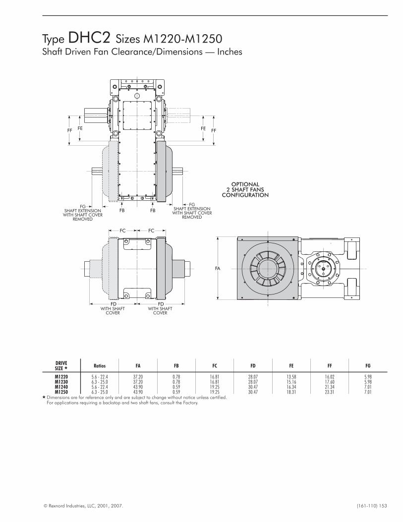
© Rexnord Industries, LLC, 2001, 2007. (161-110) 153
Type DHC2 Sizes M1220-M1250Shaft Driven Fan Clearance/Dimensions — Inches
FA
FC
FDWITH SHAFT
COVER
FB
FE FF
FGSHAFT EXTENSION
WITH SHAFT COVERREMOVED
FGSHAFT EXTENSION
WITH SHAFT COVERREMOVED
FB
FDWITH SHAFT
COVER
FC
OPTIONAL2 SHAFT FANS
CONFIGURATION
FEFF
DRIVESIZE � Ratios FA FB FC FD FE FF FG
M1220 5.6 - 22.4 37.20 0.78 16.81 28.07 13.58 16.02 5.98M1230 6.3 - 25.0 37.20 0.78 16.81 28.07 15.16 17.60 5.98M1240 5.6 - 22.4 43.90 0.59 19.25 30.47 16.34 21.34 7.01M1250 6.3 - 25.0 43.90 0.59 19.25 30.47 18.31 23.31 7.01
� Dimensions are for reference only and are subject to change without notice unless certified.For applications requiring a backstop and two shaft fans, consult the Factory.
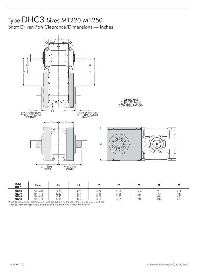
154 (161-110) © Rexnord Industries, LLC, 2001, 2007.
Type DHC3 Sizes M1220-M1250Shaft Driven Fan Clearance/Dimensions — Inches
FA
FDWITH SHAFT
COVER
FC
FGSHAFT EXTENSION
WITH SHAFT COVERREMOVED
FE
FF
FDWITH SHAFT
COVER
FC
OPTIONAL2 SHAFT FANS
CONFIGURATION
FGSHAFT EXTENSION
WITH SHAFT COVERREMOVED
FBFB
FE
FF
DRIVESIZE � Ratios FA FB FC FD FE FF FG
M1220 25.0 - 63.0 37.20 4.72 16.61 25.08 15.16 29.17 4.84M1230 28.0 - 71.0 37.20 4.72 16.61 25.08 16.73 30.75 4.84M1240 25.0 - 63.0 43.90 3.35 18.39 26.85 17.91 35.87 6.60M1250 28.0 - 71.0 43.90 3.35 18.39 26.85 19.88 37.83 6.60
� Dimensions are for reference only and are subject to change without notice unless certified.For applications requiring a backstop and two shaft fans, consult the Factory.
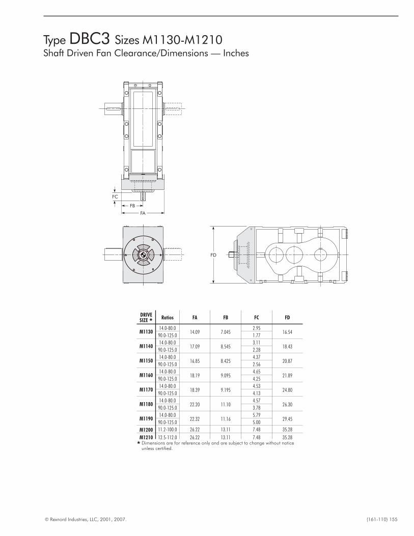
© Rexnord Industries, LLC, 2001, 2007. (161-110) 155
Type DBC3 Sizes M1130-M1210Shaft Driven Fan Clearance/Dimensions — Inches
FD
FA
FB
FC
DRIVESIZE � Ratios FA FB FC FD
M113014.0-80.0
14.09 7.0452.95
16.5490.0-125.0 1.77
M114014.0-80.0
17.09 8.5453.11
18.4390.0-125.0 2.28
M115014.0-80.0
16.85 8.4254.37
20.8790.0-125.0 2.56
M116014.0-80.0
18.19 9.0954.65
21.8990.0-125.0 4.25
M117014.0-80.0
18.39 9.1954.53
24.8090.0-125.0 4.13
M118014.0-80.0
22.20 11.104.57
26.3090.0-125.0 3.78
M119014.0-80.0
22.32 11.165.79
29.4590.0-125.0 5.00
M1200 11.2-100.0 26.22 13.11 7.48 35.28
M1210 12.5-112.0 26.22 13.11 7.48 35.28� Dimensions are for reference only and are subject to change without notice
unless certified.
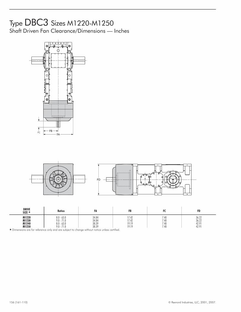
156 (161-110) © Rexnord Industries, LLC, 2001, 2007.
Type DBC3 Sizes M1220-M1250Shaft Driven Fan Clearance/Dimensions — Inches
FD
FCFB
FA
DRIVESIZE � Ratios FA FB FC FD
M1220 8.0 - 63.0 34.84 17.42 7.40 36.22M1230 9.0 - 71.0 34.84 17.42 7.40 36.22M1240 8.0 - 63.0 38.39 19.19 7.40 42.91M1250 9.0 - 71.0 38.39 19.19 7.40 42.91
� Dimensions are for reference only and are subject to change without notice unless certified.
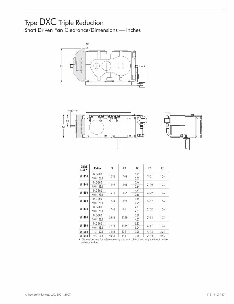
© Rexnord Industries, LLC, 2001, 2007. (161-110) 157
Type DXC Triple ReductionShaft Driven Fan Clearance/Dimensions — Inches
M
MQ
Q
L
EE
W
O D
13.80
FD
FE
FA
FB
FC
DRIVESIZE � Ratios FA FB FC FD FE
M113014.0-80.0
12.95 7.053.23
19.21 1.2690.0-125.0 2.05
M114014.0-80.0
14.92 8.033.46
21.10 1.2690.0-125.0 2.64
M115014.0-80.0
16.10 8.624.41
23.39 1.2690.0-125.0 2.60
M116014.0-80.0
17.44 9.294.65
24.57 1.2690.0-125.0 4.25
M117014.0-80.0
17.68 9.414.61
27.32 1.2690.0-125.0 4.37
M118014.0-80.0
20.55 11.105.20
29.84 1.7390.0-125.0 4.33
M119014.0-80.0
22.13 11.895.83
33.07 1.7390.0-125.0 5.04
M1200 11.2-100.0 24.53 13.11 7.20 42.13 3.35
M1210 12.5-112.0 24.53 13.11 7.20 42.13 3.35� Dimensions are for reference only and are subject to change without notice
unless certified.
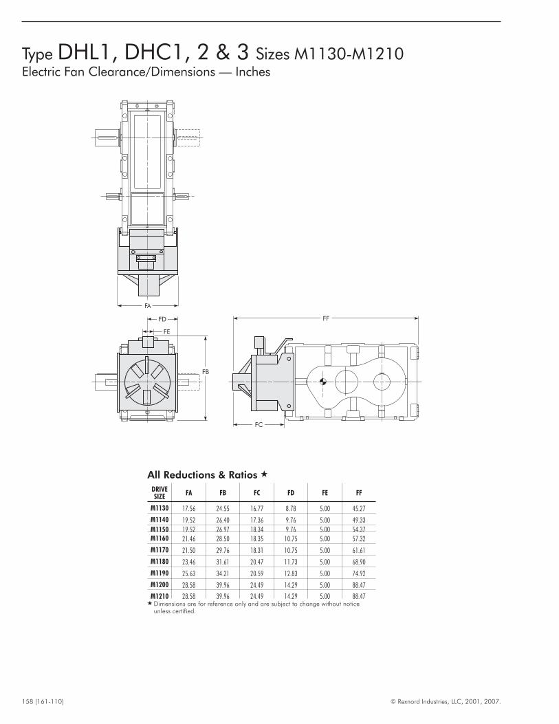
158 (161-110) © Rexnord Industries, LLC, 2001, 2007.
Type DHL1, DHC1, 2 & 3 Sizes M1130-M1210Electric Fan Clearance/Dimensions — Inches
FA
FD
FE
FB
FC
FF
All Reductions & Ratios �
DRIVESIZE
FA FB FC FD FE FF
M1130 17.56 24.55 16.77 8.78 5.00 45.27
M1140 19.52 26.40 17.36 9.76 5.00 49.33
M1150 19.52 26.97 18.34 9.76 5.00 54.37M1160 21.46 28.50 18.35 10.75 5.00 57.32
M1170 21.50 29.76 18.31 10.75 5.00 61.61
M1180 23.46 31.61 20.47 11.73 5.00 68.90
M1190 25.63 34.21 20.59 12.83 5.00 74.92
M1200 28.58 39.96 24.49 14.29 5.00 88.47
M1210 28.58 39.96 24.49 14.29 5.00 88.47� Dimensions are for reference only and are subject to change without notice
unless certified.
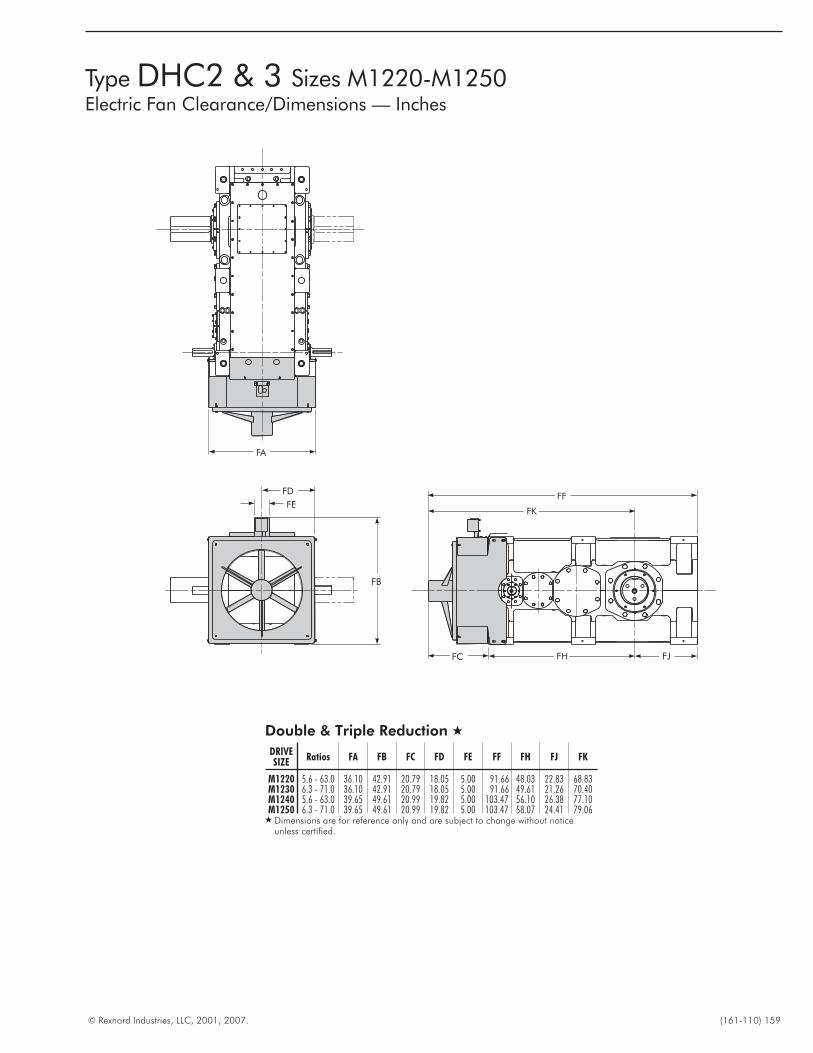
© Rexnord Industries, LLC, 2001, 2007. (161-110) 159
Type DHC2 & 3 Sizes M1220-M1250Electric Fan Clearance/Dimensions — Inches
FC
FFFE
FB
FD
FA
FK
FH FJ
Double & Triple Reduction �
DRIVESIZE
Ratios FA FB FC FD FE FF FH FJ FK
M1220 5.6 - 63.0 36.10 42.91 20.79 18.05 5.00 91.66 48.03 22.83 68.83M1230 6.3 - 71.0 36.10 42.91 20.79 18.05 5.00 91.66 49.61 21.26 70.40M1240 5.6 - 63.0 39.65 49.61 20.99 19.82 5.00 103.47 56.10 26.38 77.10M1250 6.3 - 71.0 39.65 49.61 20.99 19.82 5.00 103.47 58.07 24.41 79.06
� Dimensions are for reference only and are subject to change without noticeunless certified.
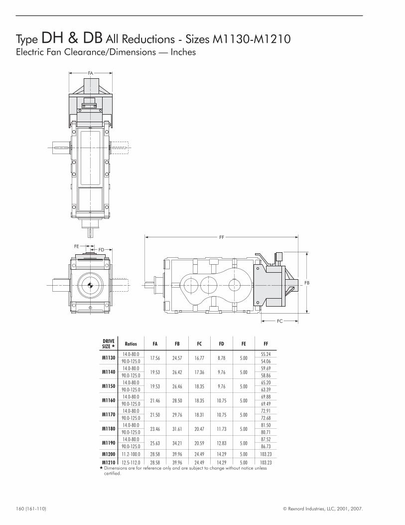
160 (161-110) © Rexnord Industries, LLC, 2001, 2007.
Type DH & DB All Reductions - Sizes M1130-M1210Electric Fan Clearance/Dimensions — Inches
FA
FEFD
FF
FC
FB
DRIVESIZE � Ratios FA FB FC FD FE FF
M113014.0-80.0
17.56 24.57 16.77 8.78 5.0055.24
90.0-125.0 54.06
M114014.0-80.0
19.53 26.42 17.36 9.76 5.0059.69
90.0-125.0 58.86
M115014.0-80.0
19.53 26.46 18.35 9.76 5.0065.20
90.0-125.0 63.39
M116014.0-80.0
21.46 28.50 18.35 10.75 5.0069.88
90.0-125.0 69.49
M117014.0-80.0
21.50 29.76 18.31 10.75 5.0072.91
90.0-125.0 72.68
M118014.0-80.0
23.46 31.61 20.47 11.73 5.0081.50
90.0-125.0 80.71
M119014.0-80.0
25.63 34.21 20.59 12.83 5.0087.52
90.0-125.0 86.73
M1200 11.2-100.0 28.58 39.96 24.49 14.29 5.00 103.23
M1210 12.5-112.0 28.58 39.96 24.49 14.29 5.00 103.23� Dimensions are for reference only and are subject to change without notice unless
certified.

© Rexnord Industries, LLC, 2001, 2007. (161-110) 161
Type DBC3 Sizes M1220-M1250Electric Fan Clearance/Dimensions — Inches
FE
FB
FD
FC
FF
FA
FK
FH FJ
FO
DRIVESIZE � Ratios FA FB FC FD FE FF FH FJ FK FO
M1220 8.0 - 63.0 36.10 42.91 20.79 18.05 5.00 120.40 48.03 22.83 43.62 76.77M1230 9.0 - 71.0 36.10 42.91 20.79 18.05 5.00 120.40 49.61 21.26 42.05 78.35M1240 8.0 - 63.0 39.65 49.61 20.99 19.82 5.00 129.45 56.10 26.38 47.36 82.09M1250 9.0 - 71.0 39.65 49.61 20.99 19.82 5.00 129.45 58.07 24.41 45.40 84.06
� Dimensions are for reference only and are subject to change without notice unlesscertified.
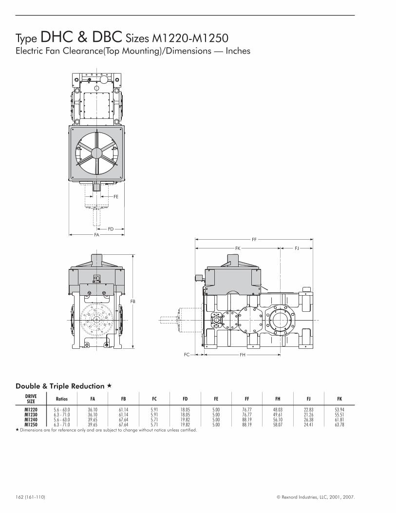
162 (161-110) © Rexnord Industries, LLC, 2001, 2007.
Type DHC & DBC Sizes M1220-M1250Electric Fan Clearance(Top Mounting)/Dimensions — Inches
FF
FC
FB
FA
FE
FD
FK FJ
FH
Double & Triple Reduction �
DRIVESIZE
Ratios FA FB FC FD FE FF FH FJ FK
M1220 5.6 - 63.0 36.10 61.14 5.91 18.05 5.00 76.77 48.03 22.83 53.94M1230 6.3 - 71.0 36.10 61.14 5.91 18.05 5.00 76.77 49.61 21.26 55.51M1240 5.6 - 63.0 39.65 67.64 5.71 19.82 5.00 88.19 56.10 26.38 61.81M1250 6.3 - 71.0 39.65 67.64 5.71 19.82 5.00 88.19 58.07 24.41 63.78
� Dimensions are for reference only and are subject to change without notice unless certified.
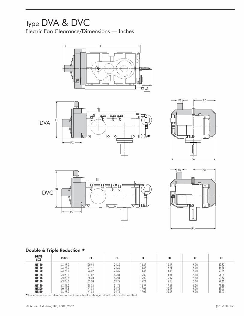
© Rexnord Industries, LLC, 2001, 2007. (161-110) 163
Type DVA & DVCElectric Fan Clearance/Dimensions — Inches
DVC
FF
DVAFB
FC
FE FD
FA
FE FD
FA
FB
FC
Double & Triple Reduction �
DRIVESIZE
Ratios FA FB FC FD FE FF
M1130 6.3-28.0 20.94 24.35 13.82 10.47 5.00 42.32M1140 6.3-28.0 24.41 24.35 14.37 12.21 5.00 46.30M1150 6.3-28.0 26.69 24.35 14.37 13.35 5.00 50.39
M1160 6.3-28.0 27.87 26.34 15.35 13.94 5.00 54.33M1170 6.3-28.0 30.63 26.34 15.35 15.32 5.00 58.66M1180 6.3-28.0 32.20 29.76 16.26 16.10 5.00 64.69
M1190 6.3-28.0 35.35 31.73 16.97 17.68 5.00 71.30M1200 5.0-22.4 41.34 34.73 17.09 20.67 5.00 81.07M1210 5.6-25.0 41.34 34.73 17.09 20.67 5.00 81.07
� Dimensions are for reference only and are subject to change without notice unless certified.
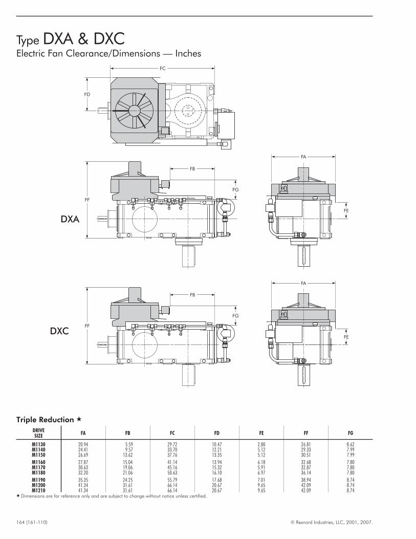
164 (161-110) © Rexnord Industries, LLC, 2001, 2007.
Type DXA & DXCElectric Fan Clearance/Dimensions — Inches
W
O D
M
MQ
Q
L
EE
13.80
DXA
DXC
FC
FD
FF
FB
FG
FA
FE
M
MQ
Q
L
EE
13.80
FA
FE
FF
FB
FG
Triple Reduction �
DRIVESIZE
FA FB FC FD FE FF FG
M1130 20.94 5.59 29.72 10.47 2.80 26.81 8.62M1140 24.41 9.57 33.70 12.21 5.12 29.33 7.99M1150 26.69 13.62 37.76 13.35 5.12 30.51 7.99
M1160 27.87 15.04 41.14 13.94 6.18 32.68 7.80M1170 30.63 19.06 45.16 15.32 5.91 32.87 7.80M1180 32.20 21.06 50.63 16.10 6.97 36.14 7.80
M1190 35.35 24.25 55.79 17.68 7.01 38.94 8.74M1200 41.34 31.61 66.14 20.67 9.65 42.09 8.74M1210 41.34 31.61 66.14 20.67 9.65 42.09 8.74
� Dimensions are for reference only and are subject to change without notice unless certified.
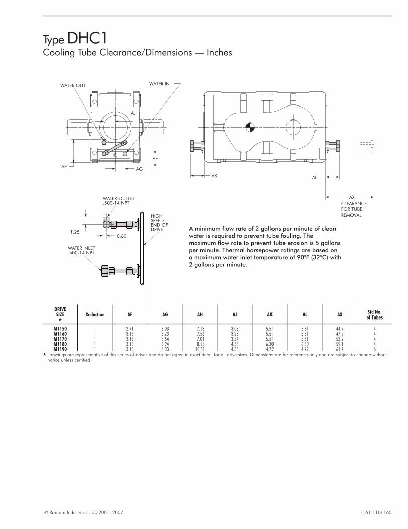
© Rexnord Industries, LLC, 2001, 2007. (161-110) 165
Type DHC1Cooling Tube Clearance/Dimensions — Inches
CLEARANCEFOR TUBEREMOVAL
WATER INWATER OUT
AX
ALAK
AF
AGAH
AJ
1.250.60
WATER INLET.500-14 NPT
WATER OUTLET.500-14 NPT
HIGHSPEEDEND OFDRIVE A minimum flow rate of 2 gallons per minute of clean
water is required to prevent tube fouling. Themaximum flow rate to prevent tube erosion is 5 gallonsper minute. Thermal horsepower ratings are based ona maximum water inlet temperature of 90°F (32°C) with2 gallons per minute.
DRIVESIZE
�Reduction AF AG AH AJ AK AL AX
Std No.of Tubes
M1150 1 2.91 3.03 7.13 3.03 5.51 5.51 44.9 4M1160 1 3.15 3.23 7.56 3.23 5.51 5.51 47.9 4M1170 1 3.15 3.54 7.01 3.54 5.51 5.51 52.2 4M1180 1 3.15 3.94 8.15 4.33 6.30 6.30 59.1 4M1190 1 3.15 4.33 10.51 4.33 4.72 4.72 61.7 6
� Drawings are representative of this series of drives and do not agree in exact detail for all drive sizes. Dimensions are for reference only and are subject to change withoutnotice unless certified.
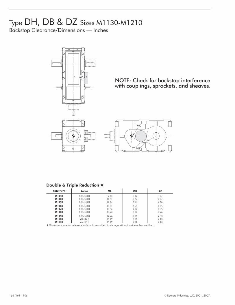
166 (161-110) © Rexnord Industries, LLC, 2001, 2007.
Type DH, DB & DZ Sizes M1130-M1210Backstop Clearance/Dimensions — Inches
MA
MB
MC
Double & Triple Reduction �
DRIVE SIZE Ratios MA MB MC
M1130 6.30-140.0 9.09 5.12 1.97M1140 6.30-140.0 10.51 5.22 2.07M1150 6.30-140.0 10.47 6.00 2.66
M1160 6.30-140.0 11.81 6.50 2.95M1170 6.30-140.0 11.54 7.09 3.35M1180 6.30-140.0 13.23 8.07 3.74
M1190 6.30-140.0 14.76 8.66 4.33M1200 5.0-112.0 19.49 8.86 4.13M1210 5.6-125.0 19.49 9.84 4.13
� Dimensions are for reference only and are subject to change without notice unless certified.
NOTE: Check for backstop interferencewith couplings, sprockets, and sheaves.
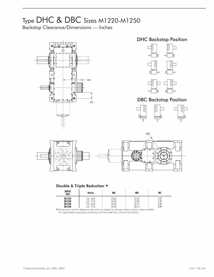
© Rexnord Industries, LLC, 2001, 2007. (161-110) 167
Type DHC & DBC Sizes M1220-M1250Backstop Clearance/Dimensions — Inches
MA
MC
MB
Double & Triple Reduction �
DRIVESIZE
Ratios MA MB MC
M1220 5.6 - 63.0 23.66 25.47 6.99M1230 6.3 - 71.0 23.66 27.05 6.99M1240 5.6 - 63.0 26.18 26.77 6.89M1250 6.3 - 71.0 26.18 28.74 6.89
� Dimensions are for reference only and are subject to change without notice unless certified.For applications requiring a backstop and two shaft fans, consult the Factory.
DHC Backstop Position
00160015
02560156
00260025
DBC Backstop Position
00460045 0456
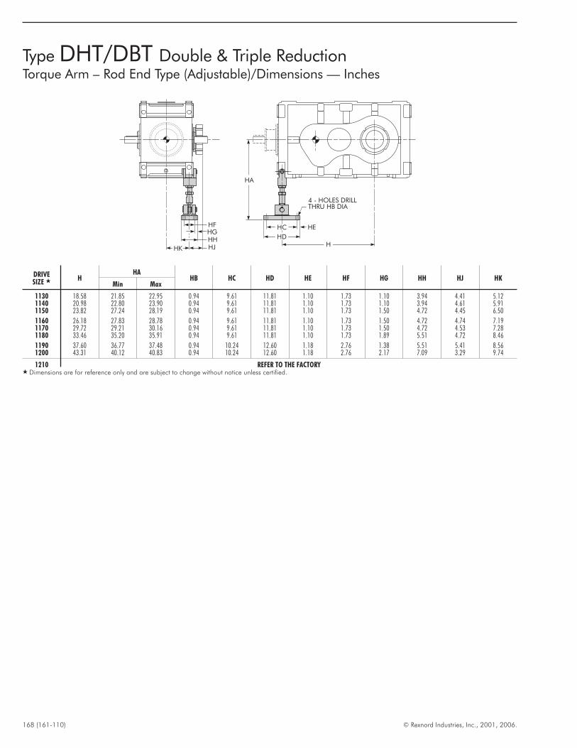
168 (161-110) © Rexnord Industries, Inc., 2001, 2006.
Type DHT/DBT Double & Triple ReductionTorque Arm – Rod End Type (Adjustable)/Dimensions — Inches
HK HJHH
HFHG
HE
4 - HOLES DRILLTHRU HB DIA
HA
H
HC
HD
DRIVESIZE � H
HAHB HC HD HE HF HG HH HJ HK
Min Max
1130 18.58 21.85 22.95 0.94 9.61 11.81 1.10 1.73 1.10 3.94 4.41 5.121140 20.98 22.80 23.90 0.94 9.61 11.81 1.10 1.73 1.10 3.94 4.61 5.911150 23.82 27.24 28.19 0.94 9.61 11.81 1.10 1.73 1.50 4.72 4.45 6.50
1160 26.18 27.83 28.78 0.94 9.61 11.81 1.10 1.73 1.50 4.72 4.74 7.191170 29.72 29.21 30.16 0.94 9.61 11.81 1.10 1.73 1.50 4.72 4.53 7.281180 33.46 35.20 35.91 0.94 9.61 11.81 1.10 1.73 1.89 5.51 4.72 8.46
1190 37.60 36.77 37.48 0.94 10.24 12.60 1.18 2.76 1.38 5.51 5.41 8.561200 43.31 40.12 40.83 0.94 10.24 12.60 1.18 2.76 2.17 7.09 3.29 9.74
1210 REFER TO THE FACTORY� Dimensions are for reference only and are subject to change without notice unless certified.
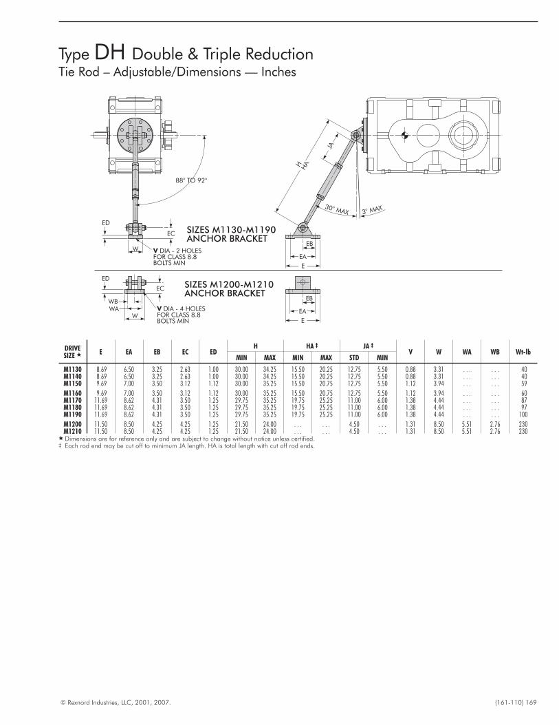
© Rexnord Industries, LLC, 2001, 2007. (161-110) 169
Type DH Double & Triple ReductionTie Rod – Adjustable/Dimensions — Inches
JA
30° MAX 3° MAX
EB
EA
E
H HA
EB
EA
E
SIZES M1130-M1190BRACKETANCHOR
SIZES M1200-M1210BRACKETANCHOR
V DIA - 2 HOLESFOR CLASS 8.8BOLTS MIN
W
EC
ED
88° TO 92°
W
EC
ED
V DIA - 4 HOLESFOR CLASS 8.8BOLTS MIN
WAWB
DRIVESIZE � E EA EB EC ED
H HA ‡ JA ‡
V W WA WB Wt-lbMIN MAX MIN MAX STD MIN
M1130 8.69 6.50 3.25 2.63 1.00 30.00 34.25 15.50 20.25 12.75 5.50 0.88 3.31 . . . . . . 40M1140 8.69 6.50 3.25 2.63 1.00 30.00 34.25 15.50 20.25 12.75 5.50 0.88 3.31 . . . . . . 40M1150 9.69 7.00 3.50 3.12 1.12 30.00 35.25 15.50 20.75 12.75 5.50 1.12 3.94 . . . . . . 59
M1160 9.69 7.00 3.50 3.12 1.12 30.00 35.25 15.50 20.75 12.75 5.50 1.12 3.94 . . . . . . 60M1170 11.69 8.62 4.31 3.50 1.25 29.75 35.25 19.75 25.25 11.00 6.00 1.38 4.44 . . . . . . 87M1180 11.69 8.62 4.31 3.50 1.25 29.75 35.25 19.75 25.25 11.00 6.00 1.38 4.44 . . . . . . 97M1190 11.69 8.62 4.31 3.50 1.25 29.75 35.25 19.75 25.25 11.00 6.00 1.38 4.44 . . . . . . 100
M1200 11.50 8.50 4.25 4.25 1.25 21.50 24.00 . . . . . . 4.50 . . . 1.31 8.50 5.51 2.76 230M1210 11.50 8.50 4.25 4.25 1.25 21.50 24.00 . . . . . . 4.50 . . . 1.31 8.50 5.51 2.76 230
� Dimensions are for reference only and are subject to change without notice unless certified.‡ Each rod end may be cut off to minimum JA length. HA is total length with cut off rod ends.
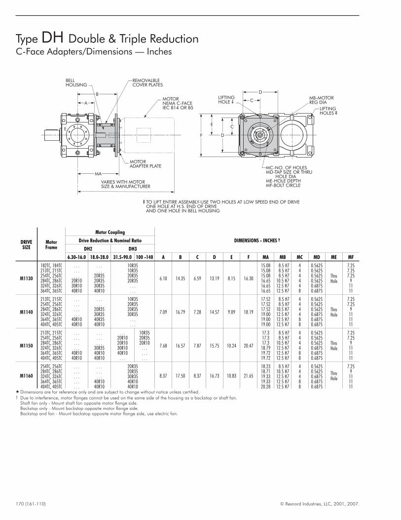
170 (161-110) © Rexnord Industries, LLC, 2001, 2007.
Type DH Double & Triple ReductionC-Face Adapters/Dimensions — Inches
TO LIFT ENTIRE ASSEMBLY-USE TWO HOLES AT LOW SPEED END OF DRIVEONE HOLE AT H.S. END OF DRIVEAND ONE HOLE IN BELL HOUSING
MC-NO. OF HOLESMD-TAP SIZE OR THRU
HOLE DIAME-HOLE DEPTHMF-BOLT CIRCLE
MB-MOTORREG DIA
LIFTINGHOLE
LIFTINGHOLES
D
C
C
D
E
F
E
BELLHOUSING
REMOVALBLECOVER PLATES
MOTORNEMA C-FACEIEC B14 OR B5
MOTORADAPTER PLATE
VARIES WITH MOTORSIZE & MANUFACTURER
B
A
MA
DRIVESIZE
MotorFrame
Motor Coupling
DIMENSIONS - INCHES †Drive Reduction & Nominal Ratio
DH2 DH3
6.30-16.0 18.0-28.0 31.5-90.0 100 -140 A B C D E F MA MB MC MD ME MF
M1130
182TC, 184TC . . . . . . 10R35
6.10 14.35 6.59 13.19 8.15 16.30
15.08 8.5 H7 4 0.5625
ThruHole
7.25213TC, 215TC . . . . . . 10R35 15.08 8.5 H7 4 0.5625 7.25254TC, 256TC . . . 20R35 20R35 15.08 8.5 H7 4 0.5625 7.25284TC, 286TC 20R10 20R35 20R35 16.65 10.5 H7 4 0.5625 9324TC, 326TC 30R10 30R35 . . . 16.65 12.5 H7 4 0.6875 11364TC, 365TC 40R10 40R10 . . . 16.65 12.5 H7 8 0.6875 11
M1140
213TC, 215TC . . . . . . 10R35
7.09 16.79 7.28 14.57 9.09 18.19
17.52 8.5 H7 4 0.5625
ThruHole
7.25254TC, 256TC . . . . . . 20R35 17.52 8.5 H7 4 0.5625 7.25284TC, 286TC . . . 20R35 20R35 17.52 10.5 H7 4 0.5625 9324TC, 326TC . . . 30R35 30R35 19.00 12.5 H7 4 0.6875 11364TC, 365TC 40R10 40R35 . . . 19.00 12.5 H7 8 0.6875 11404TC, 405TC 40R10 40R10 . . . 19.00 12.5 H7 8 0.6875 11
M1150
213TC, 215TC . . . . . . . . . 10R35
7.68 16.57 7.87 15.75 10.24 20.47
17.3 8.5 H7 4 0.5625
ThruHole
7.25254TC, 256TC . . . . . . 20R10 20R35 17.3 8.5 H7 4 0.5625 7.25284TC, 286TC . . . . . . 20R10 20R10 17.3 10.5 H7 4 0.5625 9324TC, 326TC . . . 30R35 30R10 . . . 18.79 12.5 H7 4 0.6875 11364TC, 365TC 40R10 40R10 40R10 . . . 19.72 12.5 H7 8 0.6875 11404TC, 405TC 40R10 40R10 . . . . . . 19.72 12.5 H7 8 0.6875 11
M1160
254TC, 256TC . . . . . . 20R35
8.37 17.50 8.37 16.73 10.83 21.65
18.23 8.5 H7 4 0.5625
ThruHole
7.25284TC, 286TC . . . . . . 20R35 18.71 10.5 H7 4 0.5625 9324TC, 326TC . . . . . . 30R35 19.33 12.5 H7 4 0.6875 11364TC, 365TC . . . 40R10 40R10 19.33 12.5 H7 8 0.6875 11404TC, 405TC . . . 40R10 40R10 20.28 12.5 H7 8 0.6875 11
� Dimensions are for reference only and are subject to change without notice unless certified.† Due to interference, motor flanges cannot be used on the same side of the housing as a backstop or shaft fan.
Shaft fan only - Mount shaft fan opposite motor flange side.Backstop only - Mount backstop opposite motor flange side.Backstop and fan - Mount backstop opposite motor flange side, use electric fan.
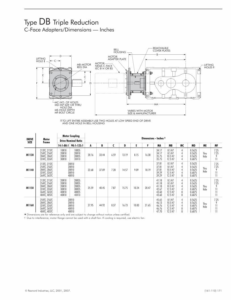
© Rexnord Industries, LLC, 2001, 2007. (161-110) 171
Type DB Triple ReductionC-Face Adapters/Dimensions — Inches
C
D
E
F
BELLHOUSING
MOTORNEMA C-FACEIEC B14 OR B5
MOTORADAPTER PLATE
VARIES WITH MOTORSIZE & MANUFACTURER
B
A
MA
TO LIFT ENTIRE ASSEMBLY-USE TWO HOLES AT LOW SPEED END OF DRIVEAND ONE HOLE IN BELL HOUSING
MC-NO. OF HOLESMD-TAP SIZE OR THRU
HOLE DIAME-HOLE DEPTHMF-BOLT CIRCLE
LIFTINGHOLES
MB-MOTORREG DIA
LIFTINGHOLE
REMOVALBLECOVER PLATES
D
C
DRIVESIZE
MotorFrame
Motor CouplingDimensions - Inches †
Drive Nominal Ratio
14:1-80:1 90:1-125:1 A B C D E F MA MB MC MD ME MF
M1130
213TC, 215TC 10R10 10R35
20.16 33.44 6.59 13.19 8.15 16.30
34.17 8.5 H7 4 0.5625ThruHole
7.25254TC, 256TC 20R10 20R10 34.17 8.5 H7 4 0.5625 7.25284TC, 286TC 20R10 20R35 35.75 10.5 H7 4 0.5625 9324TC, 326TC 30R10 30R10 35.75 12.5 H7 4 0.6875 11
M1140
213TC, 215TC 20R10
22.68 37.09 7.28 14.57 9.09 18.19
37.81 8.5 H7 4 0.5625
ThruHole
7.25254TC, 256TC 20R10 37.81 8.5 H7 4 0.5625 7.25284TC, 286TC 20R10 37.81 10.5 H7 4 0.5625 9324TC, 326TC 30R10 39.29 12.5 H7 4 0.6875 11364TC, 365TC 40R10 39.29 12.5 H7 8 0.6875 11
M1150
213TC, 215TC 20R10 20R35
25.59 40.45 7.87 15.75 10.24 20.47
41.18 8.5 H7 4 0.5625
ThruHole
7.25254TC, 256TC 20R10 20R35 41.18 8.5 H7 4 0.5625 7.25284TC, 286TC 20R10 20R35 41.18 10.5 H7 4 0.5625 9324TC, 326TC 30R10 30R35 42.67 12.5 H7 4 0.6875 11364TC, 365TC 40R10 40R35 43.60 12.5 H7 8 0.6875 11404TC, 405TC 40R10 40R10 43.60 12.5 H7 8 0.6875 11
M1160
254TC, 256TC 20R10
27.95 44.92 8.37 16.73 10.83 21.65
45.65 8.5 H7 4 0.5625
ThruHole
7.25284TC, 286TC 20R10 46.13 10.5 H7 4 0.5625 9324TC, 326TC 30R10 46.76 12.5 H7 4 0.6875 11364TC, 365TC 40R10 46.76 12.5 H7 8 0.6875 11404TC, 405TC 40R10 47.70 12.5 H7 8 0.6875 11
� Dimensions are for reference only and are subject to change without notice unless certified.† Due to interference, motor flange cannot be used with a shaft fan. If cooling is required, use electric fan.
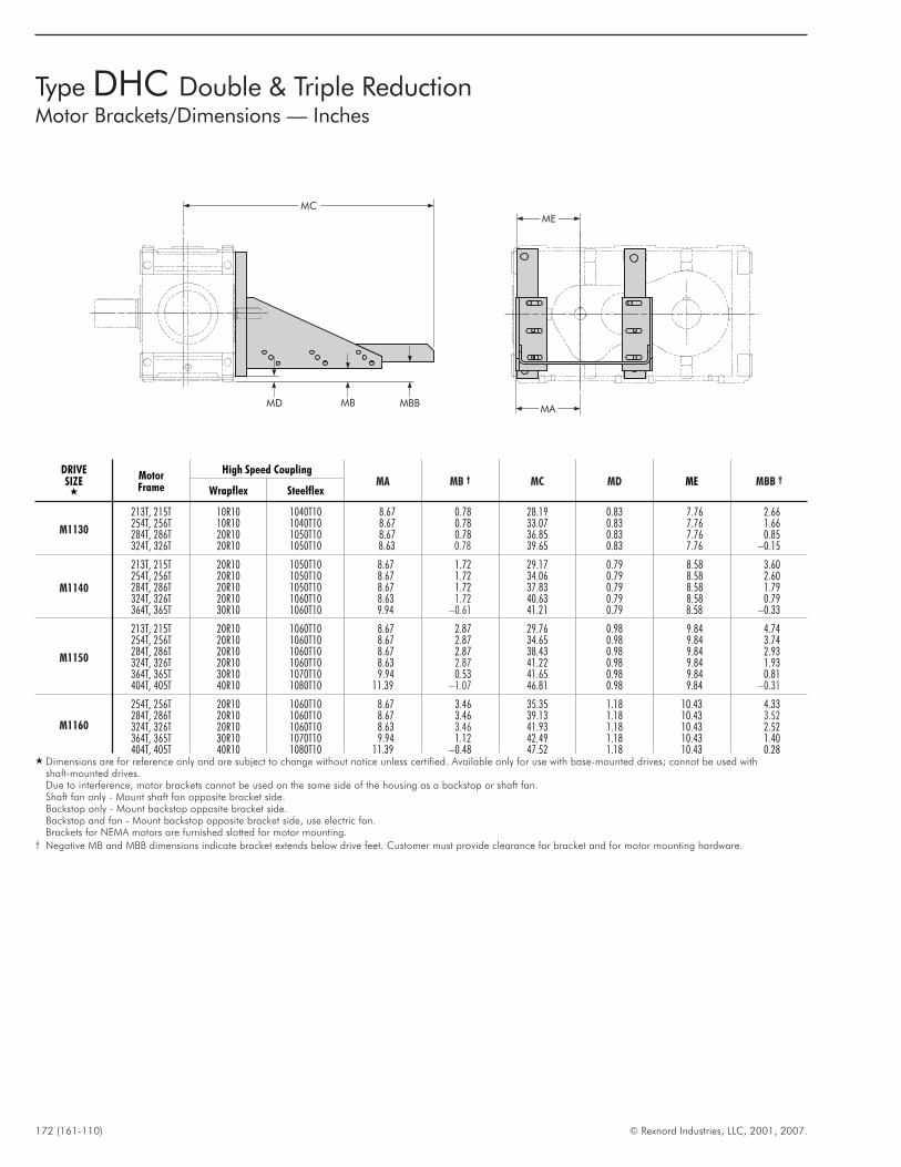
172 (161-110) © Rexnord Industries, LLC, 2001, 2007.
Type DHC Double & Triple ReductionMotor Brackets/Dimensions — Inches
ME
MA
MC
MD MB MBB
DRIVESIZE
�
MotorFrame
High Speed CouplingMA MB † MC MD ME MBB †
Wrapflex Steelflex
M1130
213T, 215T 10R10 1040T10 8.67 0.78 28.19 0.83 7.76 2.66254T, 256T 10R10 1040T10 8.67 0.78 33.07 0.83 7.76 1.66284T, 286T 20R10 1050T10 8.67 0.78 36.85 0.83 7.76 0.85324T, 326T 20R10 1050T10 8.63 0.78 39.65 0.83 7.76 –0.15
M1140
213T, 215T 20R10 1050T10 8.67 1.72 29.17 0.79 8.58 3.60254T, 256T 20R10 1050T10 8.67 1.72 34.06 0.79 8.58 2.60284T, 286T 20R10 1050T10 8.67 1.72 37.83 0.79 8.58 1.79324T, 326T 20R10 1060T10 8.63 1.72 40.63 0.79 8.58 0.79364T, 365T 30R10 1060T10 9.94 –0.61 41.21 0.79 8.58 –0.33
M1150
213T, 215T 20R10 1060T10 8.67 2.87 29.76 0.98 9.84 4.74254T, 256T 20R10 1060T10 8.67 2.87 34.65 0.98 9.84 3.74284T, 286T 20R10 1060T10 8.67 2.87 38.43 0.98 9.84 2.93324T, 326T 20R10 1060T10 8.63 2.87 41.22 0.98 9.84 1.93364T, 365T 30R10 1070T10 9.94 0.53 41.65 0.98 9.84 0.81404T, 405T 40R10 1080T10 11.39 –1.07 46.81 0.98 9.84 –0.31
M1160
254T, 256T 20R10 1060T10 8.67 3.46 35.35 1.18 10.43 4.33284T, 286T 20R10 1060T10 8.67 3.46 39.13 1.18 10.43 3.52324T, 326T 20R10 1060T10 8.63 3.46 41.93 1.18 10.43 2.52364T, 365T 30R10 1070T10 9.94 1.12 42.49 1.18 10.43 1.40404T, 405T 40R10 1080T10 11.39 –0.48 47.52 1.18 10.43 0.28
� Dimensions are for reference only and are subject to change without notice unless certified. Available only for use with base-mounted drives; cannot be used withshaft-mounted drives.Due to interference, motor brackets cannot be used on the same side of the housing as a backstop or shaft fan.Shaft fan only - Mount shaft fan opposite bracket side.Backstop only - Mount backstop opposite bracket side.Backstop and fan - Mount backstop opposite bracket side, use electric fan.Brackets for NEMA motors are furnished slotted for motor mounting.
† Negative MB and MBB dimensions indicate bracket extends below drive feet. Customer must provide clearance for bracket and for motor mounting hardware.
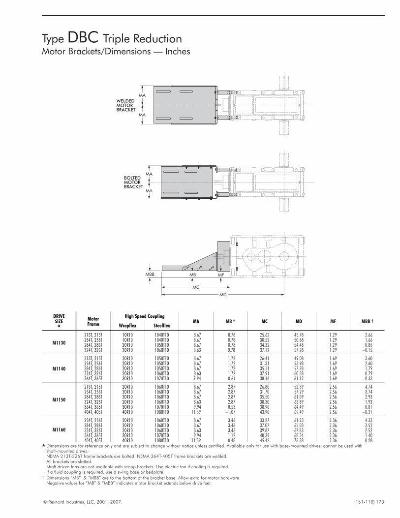
© Rexnord Industries, LLC, 2001, 2007. (161-110) 173
Type DBC Triple ReductionMotor Brackets/Dimensions — Inches
BOLTEDMOTORBRACKET
WELDEDMOTORBRACKET
MBB
MC
MD
MA
MA
MA
MA
MB MF
DRIVESIZE
�
MotorFrame
High Speed CouplingMA MB † MC MD MF MBB †
Wrapflex Steelflex
M1130
213T, 215T 10R10 1040T10 8.67 0.78 25.62 45.78 1.29 2.66254T, 256T 10R10 1040T10 8.67 0.78 30.52 50.68 1.29 1.66284T, 286T 20R10 1050T10 8.67 0.78 34.32 54.48 1.29 0.85324T, 326T 20R10 1060T10 8.63 0.78 37.12 57.28 1.29 –0.15
M1140
213T, 215T 20R10 1050T10 8.67 1.72 26.41 49.08 1.69 3.60254T, 256T 20R10 1050T10 8.67 1.72 31.31 53.98 1.69 2.60284T, 286T 20R10 1050T10 8.67 1.72 35.11 57.78 1.69 1.79324T, 326T 20R10 1060T10 8.63 1.72 37.91 60.58 1.69 0.79364T, 365T 30R10 1070T10 9.94 –0.61 38.46 61.12 1.69 –0.33
M1150
213T, 215T 20R10 1060T10 8.67 2.87 26.80 52.39 2.56 4.74254T, 256T 20R10 1060T10 8.67 2.87 31.70 57.29 2.56 3.74284T, 286T 20R10 1060T10 8.67 2.87 35.50 61.09 2.56 2.93324T, 326T 20R10 1060T10 8.63 2.87 38.30 63.89 2.56 1.93364T, 365T 30R10 1070T10 9.94 0.53 38.90 64.49 2.56 0.81404T, 405T 40R10 1080T10 11.39 –1.07 43.90 69.49 2.56 –0.31
M1160
254T, 256T 20R10 1060T10 8.67 3.46 33.27 61.23 2.36 4.33284T, 286T 20R10 1060T10 8.67 3.46 37.07 65.03 2.36 3.52324T, 326T 20R10 1060T10 8.63 3.46 39.87 67.83 2.36 2.52364T, 365T 30R10 1070T10 9.94 1.12 40.39 68.34 2.36 1.40404T, 405T 40R10 1080T10 11.39 –0.48 45.42 73.38 2.36 0.28
� Dimensions are for reference only and are subject to change without notice unless certified. Available only for use with base-mounted drives; cannot be used withshaft-mounted drives.NEMA 213T-326T frame brackets are bolted. NEMA 364T-405T frame brackets are welded.All brackets are slotted.Shaft driven fans are not available with scoop brackets. Use electric fan if cooling is required.If a fluid coupling is required, use a swing base or bedplate.
† Dimensions “MB” & “MBB” are to the bottom of the bracket base. Allow extra for motor hardware.Negative values for “MB” & “MBB” indicates motor bracket extends below drive feet.
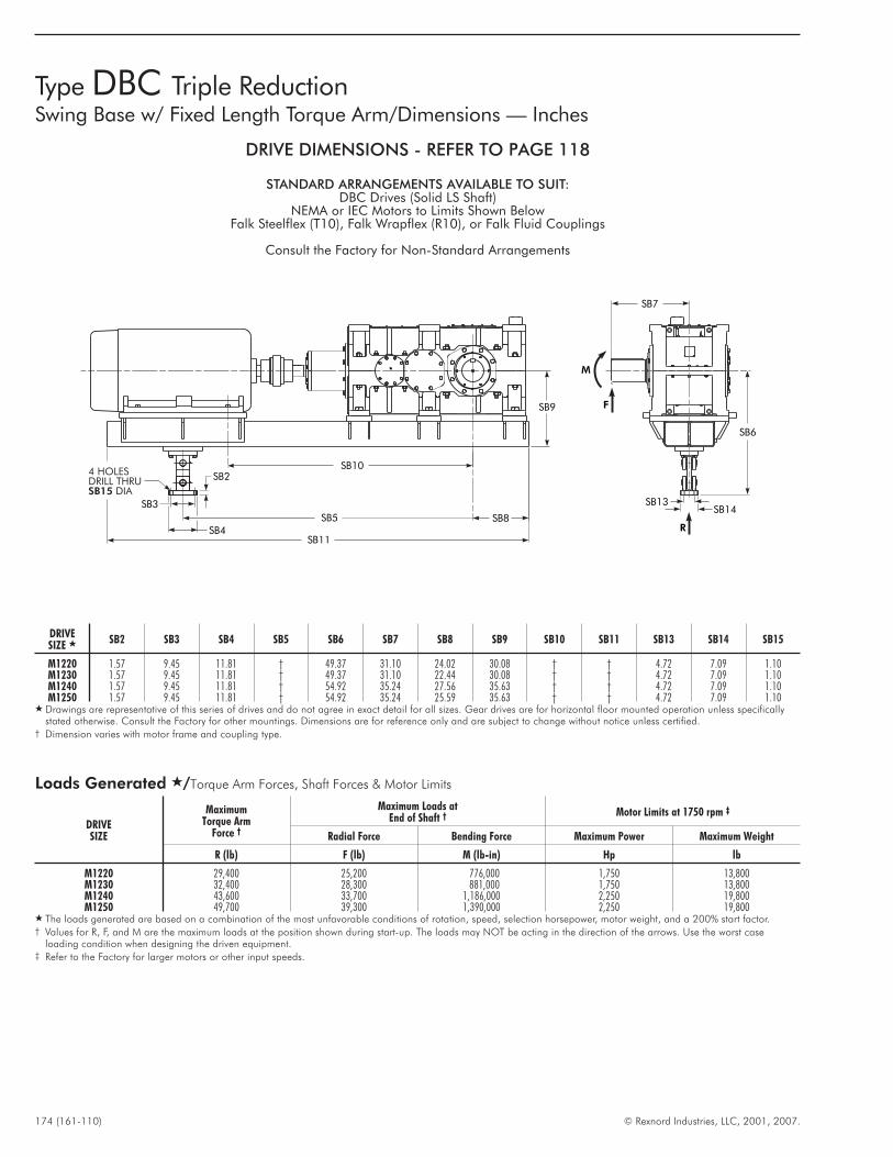
174 (161-110) © Rexnord Industries, LLC, 2001, 2007.
Type DBC Triple ReductionSwing Base w/ Fixed Length Torque Arm/Dimensions — Inches
F
R
M
SB7
SB6
SB13SB14
4 HOLESDRILL THRU
DIASB15
SB2
SB4
SB3
SB5 SB8
SB9
SB11
SB10
DRIVE DIMENSIONS - REFER TO PAGE 118
STANDARD ARRANGEMENTS AVAILABLE TO SUIT:DBC Drives (Solid LS Shaft)
NEMA or IEC Motors to Limits Shown BelowFalk Steelflex (T10), Falk Wrapflex (R10), or Falk Fluid Couplings
Consult the Factory for Non-Standard Arrangements
DRIVESIZE � SB2 SB3 SB4 SB5 SB6 SB7 SB8 SB9 SB10 SB11 SB13 SB14 SB15
M1220 1.57 9.45 11.81 † 49.37 31.10 24.02 30.08 † † 4.72 7.09 1.10M1230 1.57 9.45 11.81 † 49.37 31.10 22.44 30.08 † † 4.72 7.09 1.10M1240 1.57 9.45 11.81 † 54.92 35.24 27.56 35.63 † † 4.72 7.09 1.10M1250 1.57 9.45 11.81 † 54.92 35.24 25.59 35.63 † † 4.72 7.09 1.10
� Drawings are representative of this series of drives and do not agree in exact detail for all sizes. Gear drives are for horizontal floor mounted operation unless specificallystated otherwise. Consult the Factory for other mountings. Dimensions are for reference only and are subject to change without notice unless certified.
† Dimension varies with motor frame and coupling type.
Loads Generated �/Torque Arm Forces, Shaft Forces & Motor Limits
DRIVESIZE
MaximumTorque Arm
Force †
Maximum Loads atEnd of Shaft † Motor Limits at 1750 rpm ‡
Radial Force Bending Force Maximum Power Maximum Weight
R (lb) F (lb) M (lb-in) Hp lb
M1220 29,400 25,200 776,000 1,750 13,800M1230 32,400 28,300 881,000 1,750 13,800M1240 43,600 33,700 1,186,000 2,250 19,800M1250 49,700 39,300 1,390,000 2,250 19,800
� The loads generated are based on a combination of the most unfavorable conditions of rotation, speed, selection horsepower, motor weight, and a 200% start factor.† Values for R, F, and M are the maximum loads at the position shown during start-up. The loads may NOT be acting in the direction of the arrows. Use the worst case
loading condition when designing the driven equipment.‡ Refer to the Factory for larger motors or other input speeds.
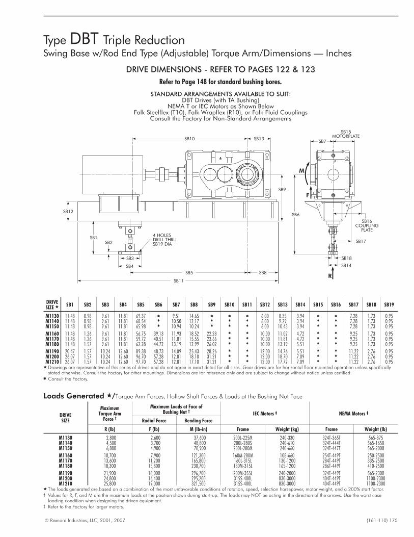
© Rexnord Industries, LLC, 2001, 2007. (161-110) 175
Type DBT Triple ReductionSwing Base w/Rod End Type (Adjustable) Torque Arm/Dimensions — Inches
DRIVE DIMENSIONS - REFER TO PAGES 122 & 123
Refer to Page 148 for standard bushing bores.
STANDARD ARRANGEMENTS AVAILABLE TO SUIT:DBT Drives (with TA Bushing)
NEMA T or IEC Motors as Shown BelowFalk Steelflex (T10), Falk Wrapflex (R10), or Falk Fluid Couplings
Consult the Factory for Non-Standard Arrangements
Loads Generated �/Torque Arm Forces, Hollow Shaft Forces & Loads at the Bushing Nut Face
DRIVESIZE
MaximumTorque Arm
Force †
Maximum Loads at Face ofBushing Nut †
IEC Motors ‡ NEMA Motors ‡
Radial Force Bending Force
R (lb) F (lb) M (lb-in) Frame Weight (kg) Frame Weight (lb)
M1130 2,800 2,600 37,600 200L-225M 240-330 324T-365T 565-875M1140 4,500 3,700 48,800 200L-280S 240-610 324T-444T 565-1650M1150 6,800 4,900 78,900 200L-280M 240-660 324T-447T 565-2000
M1160 10,700 7,900 121,300 160M-280M 108-660 254T-449T 250-2500M1170 13,600 11,200 165,800 160L-315L 130-1200 284T-449T 335-2500M1180 18,300 15,800 230,700 180M-315L 165-1200 286T-449T 410-2500
M1190 21,900 18,000 296,700 200M-355L 240-2000 324T-449T 565-2300M1200 24,800 16,400 295,200 315S-400L 830-3000 404T-449T 1100-2300M1210 25,800 19,000 321,500 315S-400L 830-3000 404T-449T 1100-2300
� The loads generated are based on a combination of the most unfavorable conditions of rotation, speed, selection horsepower, motor weight, and a 200% start factor.† Values for R, F, and M are the maximum loads at the position shown during start-up. The loads may NOT be acting in the direction of the arrows. Use the worst case
loading condition when designing the driven equipment.‡ Refer to the Factory for larger motors.
SB9
SB10
SB11
4 HOLESDRILL THRUSB19 DIA
SB5 SB8
SB13
SB3
SB4
SB2SB1
SB12
SB16COUPLING
PLATE
SB6
SB15MOTORPLATE
SB18
SB14
SB7
SB17
M
F
R
DRIVESIZE � SB1 SB2 SB3 SB4 SB5 SB6 SB7 SB8 SB9 SB10 SB11 SB12 SB13 SB14 SB15 SB16 SB17 SB18 SB19
M1130 11.48 0.98 9.61 11.81 69.37 � 9.51 14.65 � � � 6.00 8.35 3.94 � � 7.28 1.73 0.95M1140 11.48 0.98 9.61 11.81 68.54 � 10.50 12.17 � � � 6.00 9.29 3.94 � � 7.28 1.73 0.95M1150 11.48 0.98 9.61 11.81 65.98 � 10.94 10.24 � � � 6.00 10.43 3.94 � � 7.28 1.73 0.95
M1160 11.48 1.26 9.61 11.81 56.75 39.13 11.93 18.52 22.28 � � 10.00 11.02 4.72 � � 9.25 1.73 0.95M1170 11.48 1.26 9.61 11.81 59.72 40.51 11.81 15.55 23.66 � � 10.00 11.81 4.72 � � 9.25 1.73 0.95M1180 11.48 1.57 9.61 11.81 62.28 44.72 13.19 12.99 26.02 � � 10.00 13.19 5.51 � � 9.25 1.73 0.95
M1190 20.47 1.57 10.24 12.60 89.38 48.73 14.09 25.43 28.26 � � 12.00 14.76 5.51 � � 11.22 2.76 0.95M1200 26.07 1.57 10.24 12.60 96.70 57.28 12.81 18.10 31.21 � � 12.00 18.70 7.09 � � 11.22 2.76 0.95M1210 26.07 1.57 10.24 12.60 97.70 57.28 12.81 17.10 31.21 � � 12.00 17.72 7.09 � � 11.22 2.76 0.95
� Drawings are representative of this series of drives and do not agree in exact detail for all sizes. Gear drives are for horizontal floor mounted operation unless specificallystated otherwise. Consult the Factory for other mountings. Dimensions are for reference only and are subject to change without notice unless certified.
� Consult the Factory.
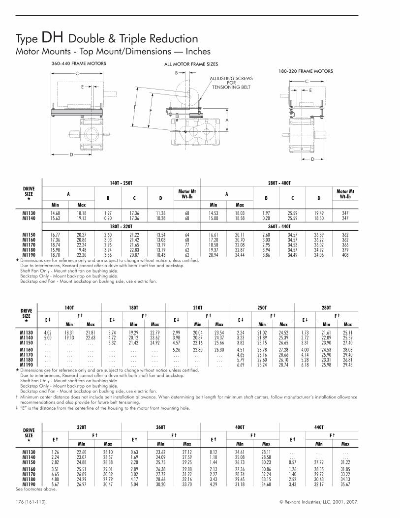
176 (161-110) © Rexnord Industries, LLC, 2001, 2007.
Type DH Double & Triple ReductionMotor Mounts - Top Mount/Dimensions — Inches
180-320 FRAME MOTORS
360-440 FRAME MOTORS
ADJUSTING SCREWSFOR
TENSIONING BELT
ALL MOTOR FRAME SIZES
C
E
D
FF
A
B
E
C
D
DRIVESIZE
�
140T - 250T 280T - 400T
AB C D
Motor MtWt-lb
AB C D
Motor MtWt-lb
Min Max Min Max
M1130 14.68 18.18 1.97 17.36 11.26 68 14.53 18.03 1.97 25.59 19.49 247M1140 15.63 19.13 0.20 17.36 10.28 68 15.08 18.58 0.20 25.59 18.50 247
180T - 320T 360T - 440T
M1150 16.77 20.27 2.60 21.22 13.54 64 16.61 20.11 2.60 34.57 26.89 362M1160 17.36 20.86 3.03 21.42 13.03 68 17.20 20.70 3.03 34.57 26.22 362M1170 18.74 22.24 2.95 21.65 13.19 77 18.58 22.08 2.95 34.53 26.02 366M1180 15.98 19.48 3.94 22.83 13.19 62 19.37 22.87 3.94 34.57 24.92 379M1190 18.70 22.20 3.86 20.87 10.43 62 20.94 24.44 3.86 34.49 24.06 408
� Dimensions are for reference only and are subject to change without notice unless certified.Due to interferences, Rexnord cannot offer a drive with both shaft fan and backstop.Shaft Fan Only - Mount shaft fan on bushing side.Backstop Only - Mount backstop on bushing side.Backstop and Fan - Mount backstop on bushing side, use electric fan.
DRIVESIZE
�
140T 180T 210T 250T 280T
E ‡F †
E ‡F †
E ‡F †
E ‡F †
E ‡F †
Min Max Min Max Min Max Min Max Min Max
M1130 4.02 18.31 21.81 3.74 19.29 22.79 2.99 20.04 23.54 2.24 21.02 24.52 1.73 21.61 25.11M1140 5.00 19.13 22.63 4.72 20.12 23.62 3.98 20.87 24.37 3.23 21.89 25.39 2.72 22.09 25.59M1150 . . . . . . . . . 5.32 21.42 24.92 4.57 22.16 25.66 3.82 23.15 26.65 3.31 23.90 27.40
M1160 . . . . . . . . . . . . . . . . . . 5.26 22.80 26.30 4.51 23.78 27.28 4.00 24.53 28.03M1170 . . . . . . . . . . . . . . . . . . . . . . . . . . . 4.65 25.16 28.66 4.14 25.90 29.40M1180 . . . . . . . . . . . . . . . . . . . . . . . . . . . 5.79 22.60 26.10 5.28 23.31 26.81M1190 . . . . . . . . . . . . . . . . . . . . . . . . . . . 6.69 25.24 28.74 6.18 25.98 29.48
� Dimensions are for reference only and are subject to change without notice unless certified.Due to interferences, Rexnord cannot offer a drive with both shaft fan and backstop.Shaft Fan Only - Mount shaft fan on bushing side.Backstop Only - Mount backstop on bushing side.Backstop and Fan - Mount backstop on bushing side, use electric fan.
† Minimum center distance does not include belt installation allowance. When determining belt length for minimum shaft centers, follow manufacturer’s installation allowancerecommendations and also provide for future belt tensioning.
‡ “E” is the distance from the centerline of the housing to the motor front mounting hole.
DRIVESIZE
�
320T 360T 400T 440T
E ‡F †
E ‡F †
E ‡F †
E ‡F †
Min Max Min Max Min Max Min Max
M1130 1.26 22.60 26.10 0.63 23.62 27.12 0.12 24.61 28.11 . . . . . . . . .M1140 2.24 23.07 26.57 1.69 24.09 27.59 1.10 25.08 28.58 . . . . . . . . .M1150 2.82 24.88 28.38 2.20 25.75 29.25 1.44 26.73 30.23 0.57 27.72 31.22
M1160 3.51 25.51 29.01 2.89 26.38 29.88 2.13 27.36 30.86 1.26 28.35 31.85M1170 6.65 26.89 30.39 3.02 27.72 31.22 2.27 28.74 32.24 1.40 29.72 33.22M1180 4.80 24.29 27.79 4.17 28.66 32.16 3.43 29.65 33.15 2.52 30.63 34.13M1190 5.67 26.97 30.47 5.04 30.20 33.70 4.29 31.18 34.68 3.43 32.17 35.67
See footnotes above.
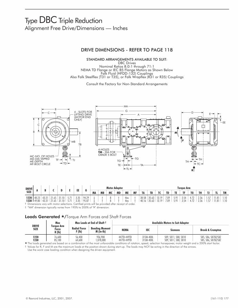
© Rexnord Industries, LLC, 2001, 2007. (161-110) 177
Type DBC Triple ReductionAlignment Free Drive/Dimensions — Inches
4 - SLOTS FORLIFTING DRIVE(MOTOR ENDONLY)
B
C
MB
MC-NO. OF HOLESMD-DIA TAPPEDME-DEPTHMF-BOLT CIRCLE
B
C
TB
TJTF
TD
MA
G
A
4-HOLES- DIA FOR
GRADE 5 BOLTTM
TGTG
TATE
TLR
F
M
DE
EE
THTH
TC
DRIVESIZE
A B C D E EE GMotor Adapter Torque Arm
MA MB MC MD ME MF TA TB TC TD TE TF TG TH TJ TL TM
1220 48.23 43.31 21.65 31.10 5.71 3.35 94.29 ‡ † 8 † thru † 38.58 35.63 13.19 7.09 5.91 3.54 4.72 2.36 1.57 11.81 1.101230 49.80 43.31 21.65 31.10 5.71 3.35 95.87 ‡ † 8 † thru † 40.16 35.63 13.19 7.09 5.91 3.54 4.72 2.36 1.57 11.81 1.10
† Dimensions vary with motor selections. Certified prints will be provided after receipt of order.‡ “MA” dimension typically varies from 195% to 200% of “A” dimension.
Loads Generated �/Torque Arm Forces and Shaft Forces
DRIVESIZE
MaxTorque Arm
ForceR (lb)
Max Loads at End of Shaft † Available Motors to Suit Adapter
Radial ForceF (lb)
Bending MomentM (in-lb)
NEMA IEC Siemens Brook & Crompton
1220 76,600 56,400 936,900 447TD-449TD 315M-400L 509, 5011, 588, 5810 585, 586, 587DZ/SDZ1230 85,100 64,600 1,078,000 447TD-449TD 315M-400L 509, 5011, 588, 5810 585, 586, 587DZ/SDZ
� The loads generated are based on a combination of the most unfavorable conditions of rotation, speed, selection horsepower, motor weight and a 200% start factor.† Values for R, F and M are the maximum loads at the position shown during start-up. The loads may NOT be acting in the direction of the arrows.
Use the worst case loading condition when designing the driven equipment.
DRIVE DIMENSIONS - REFER TO PAGE 118
STANDARD ARRANGEMENTS AVAILABLE TO SUIT:DBC Drives
Nominal Ratios 8.0:1 through 71:1NEMA TD Flange or IEC B5 Flange Motors as Shown Below
Falk Fluid (HFDD-132) CouplingsAlso Falk Steelflex (T31 or T35), or Falk Wrapflex (R31 or R35) Couplings
Consult the Factory for Non-Standard Arrangements
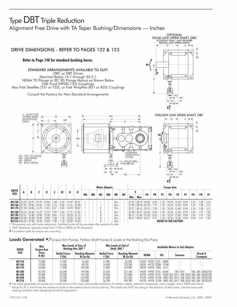
178 (161-110) © Rexnord Industries, LLC, 2001, 2007.
Type DBT Triple ReductionAlignment Free Drive with TA Taper Bushing/Dimensions — Inches
4 - SLOTS FORLIFTING DRIVE(MOTOR ENDONLY) C
C
B
B
MC - NO. OF HOLESMD - DIA TAPPEDME - DEPTHMF - BOLT CIRCLE
MB E
EE
D
P
HOLLOW LOW SPEED SHAFT, DBT
M
F
R
PBPJ
PGPH
E
EE
G
OPTIONALSOLID LOW SPEED SHAFT, DBC
(CONSULT FALK - MAY REQUIRESPECIAL LOW SPEED SHAFT)
M
F
R
PBPJ
PGPH
P
ALTERNATEINSPECTIONCOVER
MA
HA
MB
PC
4 - HOLES DRILLTHRU DIAPF
PD
PEPA
DRIVESIZE
A B C D E EE G H
Motor Adapter Torque Arm
MA MB MC MD ME MFP
PA PB PC PD PE PF PG PH PJMin Max
M1150 25.59 25.91 12.95 10.94 5.28 2.52 14.69 49.21 ‡ † † † Thru † 27.24 28.19 23.82 6.50 1.18 10.24 12.60 0.94 2.76 1.38 5.51M1160 27.95 29.06 14.53 11.93 6.16 3.50 16.61 53.94 ‡ † † † Thru † 27.83 28.78 26.18 7.19 1.18 10.24 12.60 0.94 2.76 1.38 5.51M1170 31.50 33.46 16.73 11.81 8.27 4.33 16.93 58.07 ‡ † 8 † Thru † 29.21 30.16 29.72 7.28 1.18 10.24 12.60 0.94 2.76 1.38 5.51M1180 35.24 33.46 16.73 13.19 7.09 3.54 17.91 61.81 ‡ † 8 † Thru † 35.20 35.91 33.46 8.46 1.18 10.24 12.60 0.94 3.94 1.97 7.87M1190 39.57 37.80 18.90 13.98 8.46 4.13 20.28 67.13 ‡ † 8 † Thru † 36.77 37.48 37.60 8.56 1.18 10.24 12.60 0.94 3.94 1.97 7.87M1200 45.28 37.80 18.90 13.03 7.28 1.18 23.03 77.56 ‡ † 8 † Thru † 40.12 40.83 43.31 9.76 1.18 10.24 12.60 0.94 3.94 1.97 7.87M1210 46.26 37.80 18.90 13.03 7.28 1.18 23.03 78.54 ‡ † 8 † Thru † REFER TO THE FACTORY
† Dimensions vary with motor selections. Certified prints will be provided after receipt of order.‡ “MA” dimension typically varies from 175% to 200% of “A” dimension.� Foundation hole for torque arm mounting.
Loads Generated �/Torque Arm Forces, Hollow Shaft Forces & Loads at the Bushing Nut Face
DRIVESIZE
MaxTorque Arm
ForceR (lb)
Max Loads at Face ofBushing Nut, DBT †
Max Loads at End ofShaft, DBC † Available Motors to Suit Adapter
Radial ForceF (lb)
Bending MomentM (in-lb)
Radial ForceF (lb)
Bending MomentM (in-lb)
NEMA IEC SiemensBrook &
Crompton
M1150 15,000 11,000 56,600 11,000 82,700 326TD - 445TD 225S - 280M . . . . . .M1160 19,200 14,600 80,100 14,600 122,500 365TD - 447TD 250M - 315M . . . . . .M1170 23,800 17,800 105,400 17,800 169,000 405TD - 449TD 280S - 315L . . . . . .
M1180 35,100 25,200 149,300 25,200 227,100 445TD - 449TD 315S - 355M 509, 5011 585, 586, 587DZ/SDZM1190 42,000 29,200 195,700 29,200 315,800 447TD - 449TD 315S - 355M 509, 5011, 588, 5810 585, 586, 587DZ/SDZM1200 46,400 31,900 214,900 31,600 431,500 447TD - 449TD 315M - 400L 509, 5011, 588, 5810 585, 586, 587DZ/SDZM1210 50,600 35,000 233,800 36,100 504,300 447TD - 449TD 315M - 400L 509, 5011, 588, 5810 585, 586, 587DZ/SDZ
� The loads generated are based on a combination of the most unfavorable conditions of rotation, speed, selection horsepower, motor weight, and a 200% start factor.† Values for R, F, and M are the maximum loads at the position shown during start-up. The loads may NOT be acting in the direction of the arrows. Use the worst case
loading condition when designing the driven equipment.
DRIVE DIMENSIONS - REFER TO PAGES 122 & 123
Refer to Page 148 for standard bushing bores.
STANDARD ARRANGEMENTS AVAILABLE TO SUIT:DBC or DBT Drives
Nominal Ratios 14:1 through 35.5:1NEMA TD Flange or IEC B5 Flange Motors as Shown Below
Falk Fluid (HFDD-132) CouplingsAlso Falk Steelflex (T31 or T35), or Falk Wrapflex (R31 or R35) Couplings
Consult the Factory for Non-Standard Arrangements
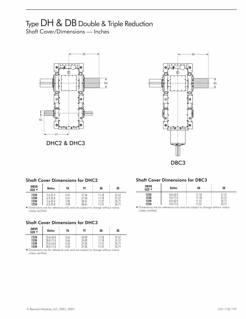
© Rexnord Industries, LLC, 2001, 2007. (161-110) 179
Type DH & DB Double & Triple ReductionShaft Cover/Dimensions — Inches
XX
XA
XX
XA
YA
YY
DHC2 & DHC3
DBC3
Shaft Cover Dimensions for DBC3
DRIVESIZE � Ratios XA XX
1220 8.0-63.0 11.18 31.571230 9.0-71.0 11.18 31.571240 8.0-63.0 11.57 35.711250 9.0-71.0 11.57 35.71
� Dimensions are for reference only and are subject to change without noticeunless certified.
Shaft Cover Dimensions for DHC2
DRIVESIZE � Ratios YA YY XA XX
1220 5.6-22.4 5.47 27.36 11.18 31.571230 6.3-25.0 5.47 27.36 11.18 31.571240 5.6-22.4 5.98 30.61 11.57 35.711250 6.3-25.0 5.98 30.61 11.57 35.71
� Dimensions are for reference only and are subject to change without noticeunless certified.
Shaft Cover Dimensions for DHC3
DRIVESIZE � Ratios YA YY XA XX
1220 25.0-63.0 3.66 24.09 11.18 31.571230 28.0-71.0 3.66 24.09 11.18 31.571240 25.0-63.0 4.53 27.05 11.57 35.711250 28.0-71.0 4.53 27.05 11.57 35.71
� Dimensions are for reference only and are subject to change without noticeunless certified.
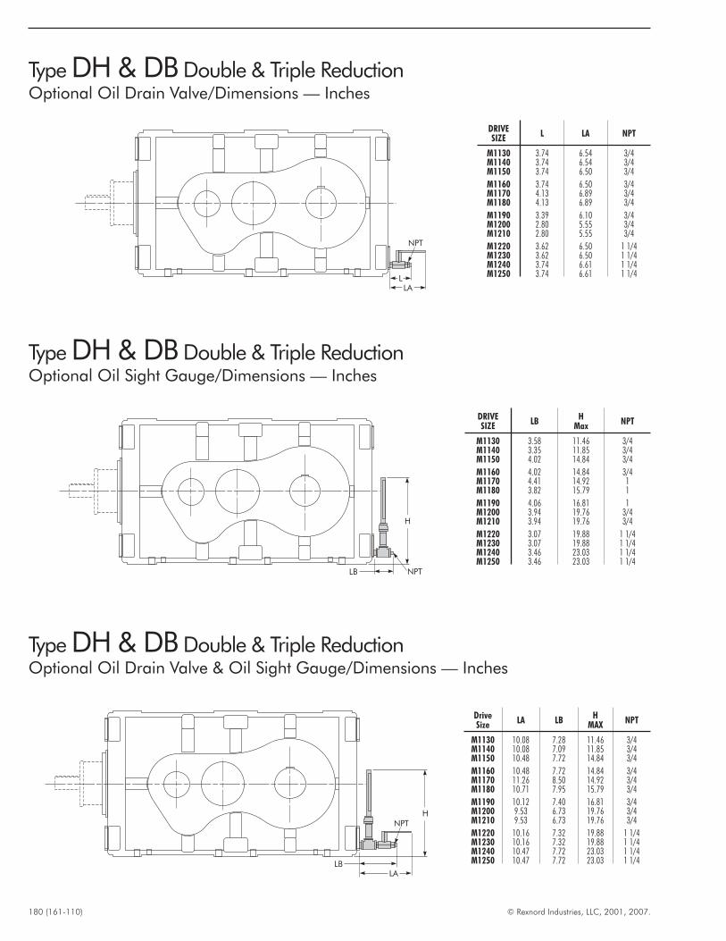
180 (161-110) © Rexnord Industries, LLC, 2001, 2007.
Type DH & DB Double & Triple ReductionOptional Oil Drain Valve/Dimensions — Inches
LLA
NPT
Type DH & DB Double & Triple ReductionOptional Oil Sight Gauge/Dimensions — Inches
NPTLB
H
DRIVESIZE
L LA NPT
M1130 3.74 6.54 3/4M1140 3.74 6.54 3/4M1150 3.74 6.50 3/4
M1160 3.74 6.50 3/4M1170 4.13 6.89 3/4M1180 4.13 6.89 3/4
M1190 3.39 6.10 3/4M1200 2.80 5.55 3/4M1210 2.80 5.55 3/4
M1220 3.62 6.50 1 1/4M1230 3.62 6.50 1 1/4M1240 3.74 6.61 1 1/4M1250 3.74 6.61 1 1/4
DRIVESIZE
LBH
MaxNPT
M1130 3.58 11.46 3/4M1140 3.35 11.85 3/4M1150 4.02 14.84 3/4
M1160 4.02 14.84 3/4M1170 4.41 14.92 1M1180 3.82 15.79 1
M1190 4.06 16.81 1M1200 3.94 19.76 3/4M1210 3.94 19.76 3/4
M1220 3.07 19.88 1 1/4M1230 3.07 19.88 1 1/4M1240 3.46 23.03 1 1/4M1250 3.46 23.03 1 1/4
Type DH & DB Double & Triple ReductionOptional Oil Drain Valve & Oil Sight Gauge/Dimensions — Inches
LA
NPT
LB
H
DriveSize
LA LBH
MAXNPT
M1130 10.08 7.28 11.46 3/4M1140 10.08 7.09 11.85 3/4M1150 10.48 7.72 14.84 3/4
M1160 10.48 7.72 14.84 3/4M1170 11.26 8.50 14.92 3/4M1180 10.71 7.95 15.79 3/4
M1190 10.12 7.40 16.81 3/4M1200 9.53 6.73 19.76 3/4M1210 9.53 6.73 19.76 3/4
M1220 10.16 7.32 19.88 1 1/4M1230 10.16 7.32 19.88 1 1/4M1240 10.47 7.72 23.03 1 1/4M1250 10.47 7.72 23.03 1 1/4
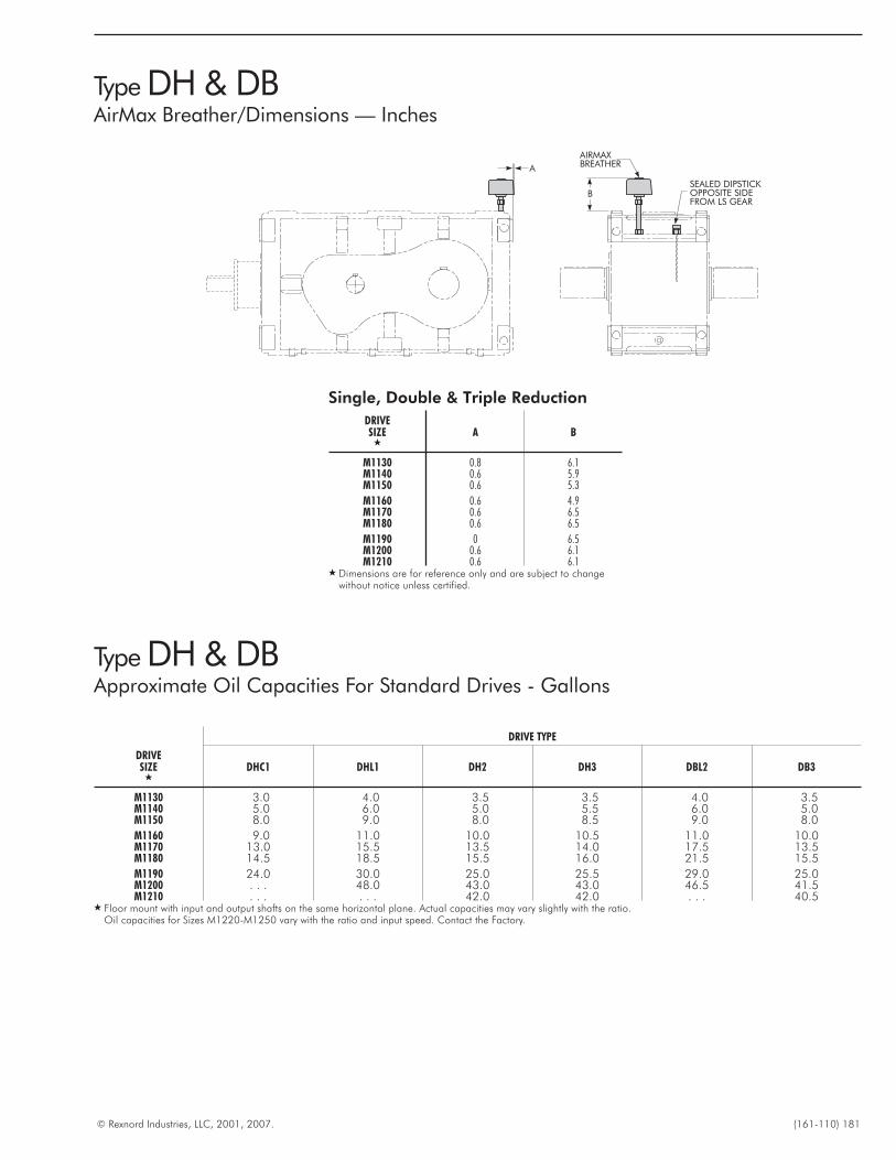
© Rexnord Industries, LLC, 2001, 2007. (161-110) 181
Type DH & DBAirMax Breather/Dimensions — Inches
AIRMAXBREATHER
SEALED DIPSTICKOPPOSITE SIDEFROM LS GEAR
A
B
Single, Double & Triple Reduction
DRIVESIZE
�A B
M1130 0.8 6.1M1140 0.6 5.9M1150 0.6 5.3
M1160 0.6 4.9M1170 0.6 6.5M1180 0.6 6.5
M1190 0 6.5M1200 0.6 6.1M1210 0.6 6.1
� Dimensions are for reference only and are subject to changewithout notice unless certified.
Type DH & DBApproximate Oil Capacities For Standard Drives - Gallons
DRIVE TYPE
DRIVESIZE
�DHC1 DHL1 DH2 DH3 DBL2 DB3
M1130 3.0 4.0 3.5 3.5 4.0 3.5M1140 5.0 6.0 5.0 5.5 6.0 5.0M1150 8.0 9.0 8.0 8.5 9.0 8.0
M1160 9.0 11.0 10.0 10.5 11.0 10.0M1170 13.0 15.5 13.5 14.0 17.5 13.5M1180 14.5 18.5 15.5 16.0 21.5 15.5
M1190 24.0 30.0 25.0 25.5 29.0 25.0M1200 . . . 48.0 43.0 43.0 46.5 41.5M1210 . . . . . . 42.0 42.0 . . . 40.5
� Floor mount with input and output shafts on the same horizontal plane. Actual capacities may vary slightly with the ratio.Oil capacities for Sizes M1220-M1250 vary with the ratio and input speed. Contact the Factory.
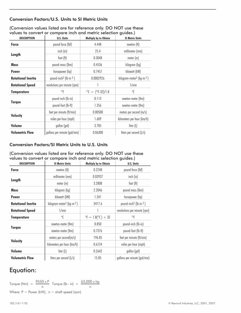
182 (161-110) © Rexnord Industries, LLC, 2001, 2007.
Equation:
Torque (Nm) =9550 x P
nTorque (lb - in) =
63,000 x hp
n
Where: P = Power (kW); n = shaft speed (rpm)
Conversion Factors/SI Metric Units to U.S. Units
(Conversion values listed are for reference only. DO NOT use thesevalues to convert or compare inch and metric selection guides.)
DESCRIPTION SI Metric Units Multiply by to Obtain U.S. Units
Force newton (N) 0.2248 pound force (lbf)
Lengthmillimeter (mm) 0.03937 inch (in)
meter (m) 3.2808 foot (ft)
Mass kilogram (kg) 2.2046 pound mass (lbm)
Power kilowatt (kW) 1.341 horsepower (hp)
Rotational Inertia kilogram-meter2 (kg-m 2 ) 3417.6 pound-inch2 (lb-in 2 )
Rotational Speed 1/min 1 revolutions per minute (rpm)
Temperature ºC ºF = 1.8(ºC ) + 32 ºF
Torquenewton-meter (Nm) 8.850 pound-inch (lb-in)
newton-meter (Nm) 0.7376 pound-foot (lb-ft)
Velocitymeters per second(m/s) 196.85 feet per minute (ft/min)
kilometers per hour (km/h) 0.6124 miles per hour (mph)
Volume liter (L) 0.2642 gallon (gal)
Volumetric Flow liters per second (L/s) 15.85 gallons per minute (gal/min)
Conversion Factors/U.S. Units to SI Metric Units
(Conversion values listed are for reference only. DO NOT use thesevalues to convert or compare inch and metric selection guides.)
DESCRIPTION U.S. Units Multiply by to Obtain SI Metric Units
Force pound force (lbf) 4.448 newton (N)
Lengthinch (in) 25.4 millimeter (mm)
foot (ft) 0.3048 meter (m)
Mass pound mass (lbm) 0.4536 kilogram (kg)
Power horsepower (hp) 0.7457 kilowatt (kW)
Rotational Inertia pound-inch2 (lb-in 2 ) 0.0002926 kilogram-meter2 (kg-m 2 )
Rotational Speed revolutions per minute (rpm) 1 1/min
Temperature ºF ºC = (ºF-32)/1.8 ºC
Torquepound-inch (lb-in) 0.113 newton-meter (Nm)
pound-foot (lb-ft) 1.356 newton-meter (Nm)
Velocityfeet per minute (ft/min) 0.00508 meters per second (m/s)
miles per hour (mph) 1.609 kilometers per hour (km/h)
Volume gallon (gal) 3.785 liter (L)
Volumetric Flow gallons per minute (gal/min) 0.06308 liters per second (L/s)
Related Documents