1 Copyright © 2009 Cordys. All Rights Reserved. www.bptrends.com BPTrends ▪ February 2009 An Approach to Case Based Management Case Management: Cordys Approach Henk de Man This article, like the previous one by Henk de Man, explores the idea of case management. In essence, dynamic processes that deal with unique cases may require different analysis techniques and different notation than more conventional processes. The OMG is exploring this possibility, and Mr. de Man has proposed one approach. In the first article he defined the problem as he sees it and considered some options. In this paper he discusses one concrete way to approach documenting and managing case-based processes. In keeping with the OMG's requirements, any proposed standard must be implemented by one of the companies proposing the standard, and in this second article Henk walks through an example of how a case could be dealt with via the implementation that Cordys has proposed to the OMG. Recap and objective In the January Update, we reviewed and evaluated various approaches to model case management processes.. We found it useful to distinguish the following types of cases: • Mass cases. These cases can be almost completely automated and managed via “workflow management”. BPMN is an adequate modeling tool for such cases.. • Regular cases. Here, the human worker is in control of how the process evolves, but the degree of freedom of the worker can be constrained by a number of elements, for example by business rules, evaluating on the case data (“case file”), to control applicability and availability of case activities to choose from, and by case states that can be used to phase the work over the life cycle of the case. Instances of regular cases show sufficient commonality to enable abstraction of such business rules and life cycle states. Case planning and progress monitoring could also be based on such states. It might be useful at this point to distinguish between “milestones” and “states”. Managers need to have “insight in matter status”. “Matter status” means case status. A state becomes a “milestone” when planned dates, deadlines, etc. are set for it. Thus, “states” become a (logistical) planning instrument. • Special cases. In these cases, the user has plenty of freedom to handle them and is supported in his or her decision making. We also noted that, especially in the beginning, when the company begins to formalize case management practice, it isl often difficult to specify business rules to control the applicability of case activities. Sometimes it is impossible to specify such rules (“special” cases), and sometimes the company will have to “learn” first, such may even be the case in some “regular cases”. Maybe many cases start as “special” and subsequently become “regular.” Case instances may first evolve based on case worker decisions. Exploring (or “mining”) case instance history might reveal certain recurring patterns. Sometimes, sequential workflows (sub-processes) might be abstracted from these patterns, and sometimes, for “regular cases”, state- and rule based constructs might be abstracted. In this way, case models might evolve over time. In this paper we will show how the Cordys case management modeling approach explicitly supports modeling of how case workers can define the process themselves, as part of their

Welcome message from author
This document is posted to help you gain knowledge. Please leave a comment to let me know what you think about it! Share it to your friends and learn new things together.
Transcript
1 Copyright © 2009 Cordys. All Rights Reserved. www.bptrends.com
BPTrends ▪ February 2009 An Approach to Case Based Management
Case Management: Cordys Approach
Henk de Man This article, like the previous one by Henk de Man, explores the idea of case management. In essence, dynamic processes that deal with unique cases may require different analysis techniques and different notation than more conventional processes. The OMG is exploring this possibility, and Mr. de Man has proposed one approach. In the first article he defined the problem as he sees it and considered some options. In this paper he discusses one concrete way to approach documenting and managing case-based processes.
In keeping with the OMG's requirements, any proposed standard must be implemented by one of the companies proposing the standard, and in this second article Henk walks through an example of how a case could be dealt with via the implementation that Cordys has proposed to the OMG.
Recap and objective In the January Update, we reviewed and evaluated various approaches to model case management processes..
We found it useful to distinguish the following types of cases:
• Mass cases. These cases can be almost completely automated and managed via “workflow management”. BPMN is an adequate modeling tool for such cases..
• Regular cases. Here, the human worker is in control of how the process evolves, but the
degree of freedom of the worker can be constrained by a number of elements, for example by business rules, evaluating on the case data (“case file”), to control applicability and availability of case activities to choose from, and by case states that can be used to phase the work over the life cycle of the case. Instances of regular cases show sufficient commonality to enable abstraction of such business rules and life cycle states. Case planning and progress monitoring could also be based on such states. It might be useful at this point to distinguish between “milestones” and “states”. Managers need to have “insight in matter status”. “Matter status” means case status. A state becomes a “milestone” when planned dates, deadlines, etc. are set for it. Thus, “states” become a (logistical) planning instrument.
• Special cases. In these cases, the user has plenty of freedom to handle them and is
supported in his or her decision making.
We also noted that, especially in the beginning, when the company begins to formalize case management practice, it isl often difficult to specify business rules to control the applicability of case activities. Sometimes it is impossible to specify such rules (“special” cases), and sometimes the company will have to “learn” first, such may even be the case in some “regular cases”. Maybe many cases start as “special” and subsequently become “regular.” Case instances may first evolve based on case worker decisions. Exploring (or “mining”) case instance history might reveal certain recurring patterns. Sometimes, sequential workflows (sub-processes) might be abstracted from these patterns, and sometimes, for “regular cases”, state- and rule based constructs might be abstracted. In this way, case models might evolve over time.
In this paper we will show how the Cordys case management modeling approach explicitly supports modeling of how case workers can define the process themselves, as part of their
2 Copyright © 2009 Cordys. All Rights Reserved. www.bptrends.com
BPTrends ▪ February 2009 An Approach to Case Based Management
process work. We will also show, especially in the context of the “regular cases”, how case data (or “case file”)-related life cycle states, events and conditions (rules) can further guide the case workers in defining the process as it goes.
In the next section we will explain some typical modeling constructs that Cordys uses to support modeling case management processes. We will do that by means of a use case: calamity handling in Railways. In the last section we will consider some opportunities for further advancement of the approach.
Cordys Case Management approach explained based on a use case: calamity handling in railways The illustrations below represent model fragments that were actually modeled in the workbench of the Cordys Case Management Designer. These models are completely run-time enabled. They are executed by the Cordys process engine (“what you model is what you execute”).
Situation: A train comes to a stand-still, possibly as a result of an accident or a technical problem. There is a major delay that effects other stations and other trains as well. The case (“case file”) represents the calamity itself and all related information. We will consider only some fragments of the total case management model. We also popularize the case a bit to facilitate easy understanding by the reader. The focus here is on explaining modeling constructs, not on overseeing and understanding a real-life case in all detail.
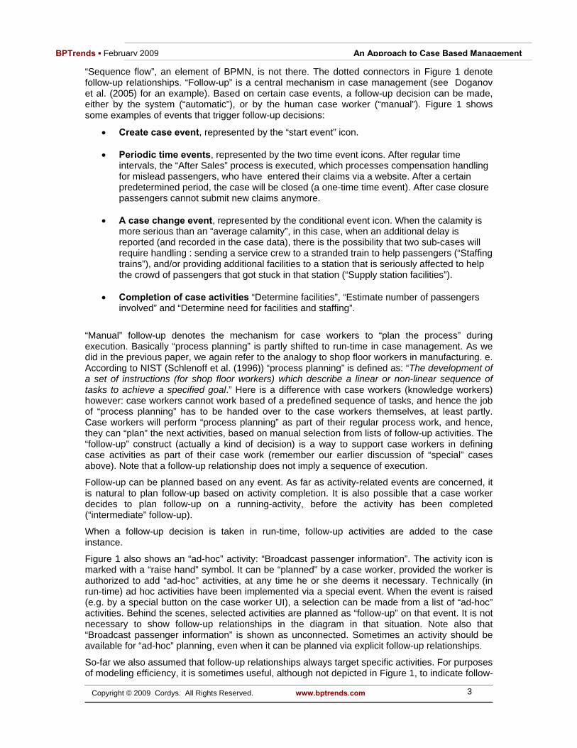
Figure 1 shows three types of activity icons. Activities like “Determine facilities” are the activities (case tasks) that are executed by case workers. Activities like “Staffing trains” denote sub-cases (the case being decomposable). “After Sales” denotes a sequential workflow (a BPMN process in itself). Sequential workflows can be started from a case process. A sequential workflow, which shows as an activity in a case management diagram, can be decomposed in a separate, BPMN-style, diagram. Integration in the other direction is also supported: a case can be created from a sequential workflow.
Figure 1: Railway calamity case handling overview
3 Copyright © 2009 Cordys. All Rights Reserved. www.bptrends.com
BPTrends ▪ February 2009 An Approach to Case Based Management
“Sequence flow”, an element of BPMN, is not there. The dotted connectors in Figure 1 denote follow-up relationships. “Follow-up” is a central mechanism in case management (see Doganov et al. (2005) for an example). Based on certain case events, a follow-up decision can be made, either by the system (“automatic”), or by the human case worker (“manual”). Figure 1 shows some examples of events that trigger follow-up decisions:
• Create case event, represented by the “start event” icon. • Periodic time events, represented by the two time event icons. After regular time
intervals, the “After Sales” process is executed, which processes compensation handling for mislead passengers, who have entered their claims via a website. After a certain predetermined period, the case will be closed (a one-time time event). After case closure passengers cannot submit new claims anymore.
• A case change event, represented by the conditional event icon. When the calamity is
more serious than an “average calamity”, in this case, when an additional delay is reported (and recorded in the case data), there is the possibility that two sub-cases will require handling : sending a service crew to a stranded train to help passengers (“Staffing trains”), and/or providing additional facilities to a station that is seriously affected to help the crowd of passengers that got stuck in that station (“Supply station facilities”).
• Completion of case activities “Determine facilities”, “Estimate number of passengers
involved” and “Determine need for facilities and staffing”.
“Manual” follow-up denotes the mechanism for case workers to “plan the process” during execution. Basically “process planning” is partly shifted to run-time in case management. As we did in the previous paper, we again refer to the analogy to shop floor workers in manufacturing. e. According to NIST (Schlenoff et al. (1996)) “process planning” is defined as: “The development of a set of instructions (for shop floor workers) which describe a linear or non-linear sequence of tasks to achieve a specified goal.” Here is a difference with case workers (knowledge workers) however: case workers cannot work based of a predefined sequence of tasks, and hence the job of “process planning” has to be handed over to the case workers themselves, at least partly. Case workers will perform “process planning” as part of their regular process work, and hence, they can “plan” the next activities, based on manual selection from lists of follow-up activities. The “follow-up” construct (actually a kind of decision) is a way to support case workers in defining case activities as part of their case work (remember our earlier discussion of “special” cases above). Note that a follow-up relationship does not imply a sequence of execution.
Follow-up can be planned based on any event. As far as activity-related events are concerned, it is natural to plan follow-up based on activity completion. It is also possible that a case worker decides to plan follow-up on a running-activity, before the activity has been completed (“intermediate” follow-up).
When a follow-up decision is taken in run-time, follow-up activities are added to the case instance.
Figure 1 also shows an “ad-hoc” activity: “Broadcast passenger information”. The activity icon is marked with a “raise hand” symbol. It can be “planned” by a case worker, provided the worker is authorized to add “ad-hoc” activities, at any time he or she deems it necessary. Technically (in run-time) ad hoc activities have been implemented via a special event. When the event is raised (e.g. by a special button on the case worker UI), a selection can be made from a list of “ad-hoc” activities. Behind the scenes, selected activities are planned as “follow-up” on that event. It is not necessary to show follow-up relationships in the diagram in that situation. Note also that “Broadcast passenger information” is shown as unconnected. Sometimes an activity should be available for “ad-hoc” planning, even when it can be planned via explicit follow-up relationships.
So-far we also assumed that follow-up relationships always target specific activities. For purposes of modeling efficiency, it is sometimes useful, although not depicted in Figure 1, to indicate follow-

4 Copyright © 2009 Cordys. All Rights Reserved. www.bptrends.com
BPTrends ▪ February 2009 An Approach to Case Based Management
up in a more implicit way, indicating that follow-up is possible to “any” activity (e.g. by a short follow-up relationship ending in a * symbol).
Note: The term “ad-hoc” should not be confused with “ad-hoc” in the sense of a BPMN “ad-hoc” sub-process. An “ad-hoc” sub-process in BPMN, like any other BPMN process, does not include the notion of a central case data context which is shared across any activity that is executed in the context of the case. And next, we want to model more than just a set of unconnected activities. Note that a case process can (theoretically) be so flexible that it is just a set of activities that can be planned in “ad-hoc” way. This could be shown as a diagram which just contains a set of unconnected activities. This is not a usual situation however. Basically “nothing” would have been modeled by that. The focus is not on modeling “perfect flexibility”, but on modeling “constrained flexibility”. Normally there are at least some guidelines and limitations that need to be modeled.
Later in this document we will discuss how follow-up can be filtered further based on applicability rules.
Figure 1 also shows how sequential workflow processes and sub-cases can be planned via follow-up. In the following two diagrams, the two sub-cases are shown. Note that, although in Figure 1, both of the sub-cases are shown as collapsed, it would also be possible to show them as expanded at that level. Figure 2 depicts the “Staffing trains” sub-case, and Figure 3 depicts the “Supply station facilities” sub-case. “Staffing trains” is about sending a service team to the stranded train, and it also supports the provisioning of special services, to be handled by the service team to help the passengers in the train.
Figure 2: Staffing trains sub-case
Figure 2 introduces the notion of an activity cluster. “Service team staffing” and “Special services” are activity clusters. An activity cluster serves several purposes:
• Functional grouping of activities, not only in design-time, but also in run-time: the grouping can also provide structure to the case worker’s UI and to process statistics in Business Activity Monitoring (BAM).

5 Copyright © 2009 Cordys. All Rights Reserved. www.bptrends.com
BPTrends ▪ February 2009 An Approach to Case Based Management
• Efficiency in specification of follow-up: When a follow-up relationship has the activity
cluster itself as a target, all activities that are contained by the cluster are added (or can be added, in the case of manual follow-up) to the case instance (in run-time). When the follow-up relationship has a specific activity within the activity cluster as a target, only that activity will be (or can be) added to the case instance.
The concept of activity clusters, in the context of case management, has been proposed by Goebl et al. (2001) also.
Note that the activity clusters in Figure 2 contain one or more activities that can be planned in an “ad-hoc” way.
Upon the creation of the sub-case, “Send service team” and “Recall service team” are the only activities that are planned. They are planned automatically by the system. This does not imply, however, that both are to be executed immediately. A case worker, in this case the calamity coordinator, will decide when and in which sequence the activities will be executed. Logically, re-calling the service team would be done after sending it. Therefore there is a sequence restriction, indicated by the “before” connector in Figure 2. This sequence restriction has a different meaning than a sequence flow connector in BPMN. It is not required (and even not logical) that “Recall service team” is executed immediately after “Send service team” has been completed. Other activities will normally be executed in between, like one or more of the “ad-hoc” activities. Even when no other activities are planned, it is still the calamity coordinator who will decide when the service team has to be called back, based, for example. on phone conversations between the coordinator and the service team on the train. In any case, as soon as the service team has been called back, the sub-case ends automatically.
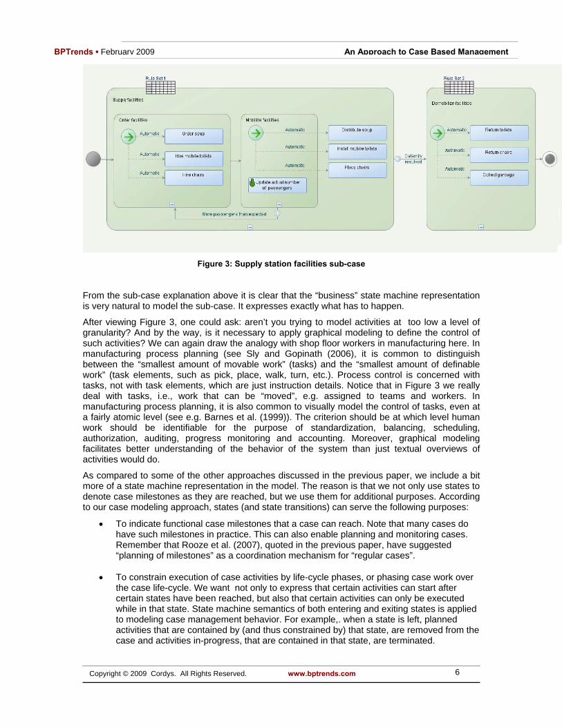
Figure 3 is about the “Supply station facilities” sub-case. It introduces some more modeling constructs. The sub-case has a life-cycle (which maps to state-machine in the background in run-time). The sub-case starts in the state “Order facilities”. Three activities are automatically planned as follow-up on the entry in that state (indicated by the event icon with green arrow). Applicability of these activities is filtered based on rules (in Rule Set 1), however, as we will explain below. After these activities have been completed, the sub-case transits to the state “Mobilize facilities.” In that state, the “Update actual number of passengers” activity can be used at any moment. For example, when it appears that the number of stranded passengers in the station is much higher than expected, it will be necessary to order more soup, and/or chairs and/or toilets. Based on the registration of the updated number of passengers in the case data, a case event will be raised, which will trigger the transition back to the ordering state. However personnel who are busy distributing the soup that had already been ordered the first time, should continue to do so. “Distribute soup”, as well as “Install mobile toilets” and “Place chairs” should not be terminated. For this reason, although these activities are only added to the case instance on entry of the state “Mobilize facilities,” they are contained in the parent state “Supply facilities.” At a certain moment, for example as a result of a phone conversation, the calamity coordinator learns that the calamity has been resolved. He then enters this fact in the case data, and at this point, the “Calamity resolved” event will be raised, which in turn triggers the transition to the state “Demobilize facilities”. Any activity that is going on in the “Supply facilities” state should be terminated then.
6 Copyright © 2009 Cordys. All Rights Reserved. www.bptrends.com
BPTrends ▪ February 2009 An Approach to Case Based Management
Figure 3: Supply station facilities sub-case
From the sub-case explanation above it is clear that the “business” state machine representation is very natural to model the sub-case. It expresses exactly what has to happen.
After viewing Figure 3, one could ask: aren’t you trying to model activities at too low a level of granularity? And by the way, is it necessary to apply graphical modeling to define the control of such activities? We can again draw the analogy with shop floor workers in manufacturing here. In manufacturing process planning (see Sly and Gopinath (2006), it is common to distinguish between the “smallest amount of movable work” (tasks) and the “smallest amount of definable work” (task elements, such as pick, place, walk, turn, etc.). Process control is concerned with tasks, not with task elements, which are just instruction details. Notice that in Figure 3 we really deal with tasks, i.e., work that can be “moved”, e.g. assigned to teams and workers. In manufacturing process planning, it is also common to visually model the control of tasks, even at a fairly atomic level (see e.g. Barnes et al. (1999)). The criterion should be at which level human work should be identifiable for the purpose of standardization, balancing, scheduling, authorization, auditing, progress monitoring and accounting. Moreover, graphical modeling facilitates better understanding of the behavior of the system than just textual overviews of activities would do.
As compared to some of the other approaches discussed in the previous paper, we include a bit more of a state machine representation in the model. The reason is that we not only use states to denote case milestones as they are reached, but we use them for additional purposes. According to our case modeling approach, states (and state transitions) can serve the following purposes:
• To indicate functional case milestones that a case can reach. Note that many cases do have such milestones in practice. This can also enable planning and monitoring cases. Remember that Rooze et al. (2007), quoted in the previous paper, have suggested “planning of milestones” as a coordination mechanism for “regular cases”.
• To constrain execution of case activities by life-cycle phases, or phasing case work over
the case life-cycle. We want not only to express that certain activities can start after certain states have been reached, but also that certain activities can only be executed while in that state. State machine semantics of both entering and exiting states is applied to modeling case management behavior. For example,. when a state is left, planned activities that are contained by (and thus constrained by) that state, are removed from the case and activities in-progress, that are contained in that state, are terminated.
7 Copyright © 2009 Cordys. All Rights Reserved. www.bptrends.com
BPTrends ▪ February 2009 An Approach to Case Based Management
• To Indicate which applicability rules (rule sets) apply in which phases of the case life-cycle.
For the purpose of model-execution in run-time, the state machine related model constructs a map to a UML-based state machine model in the back-end. Even when the case model does not include case states explicitly, a state machine instance of the case instance still resides in the backend. Remember the “Additional delay reported” event and the two time events in Figure 1. These events would map to “local transitions” in a UML-based state machine.
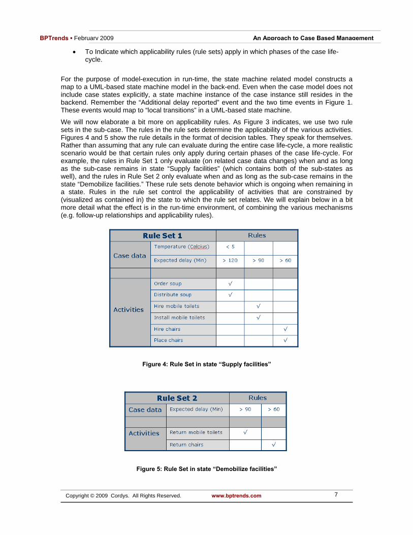
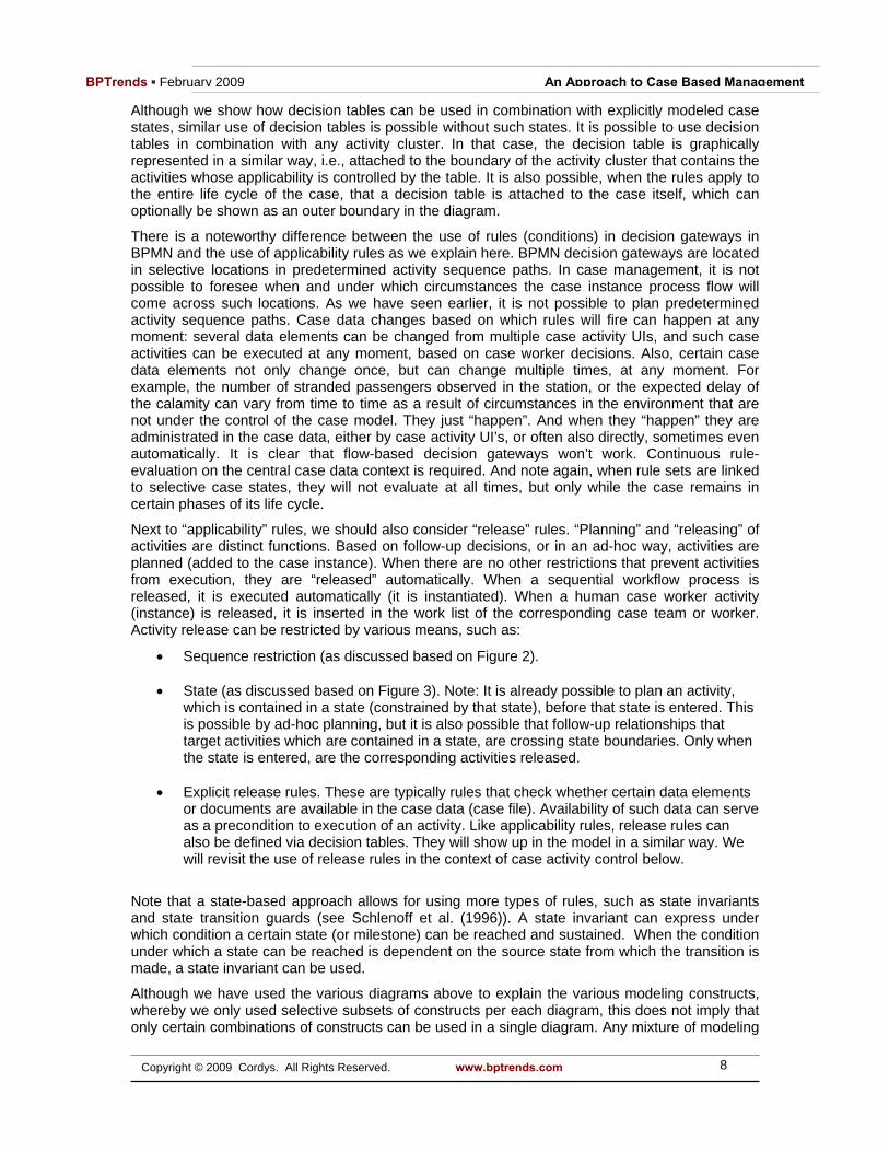
We will now elaborate a bit more on applicability rules. As Figure 3 indicates, we use two rule sets in the sub-case. The rules in the rule sets determine the applicability of the various activities. Figures 4 and 5 show the rule details in the format of decision tables. They speak for themselves. Rather than assuming that any rule can evaluate during the entire case life-cycle, a more realistic scenario would be that certain rules only apply during certain phases of the case life-cycle. For example, the rules in Rule Set 1 only evaluate (on related case data changes) when and as long as the sub-case remains in state “Supply facilities” (which contains both of the sub-states as well), and the rules in Rule Set 2 only evaluate when and as long as the sub-case remains in the state “Demobilize facilities.” These rule sets denote behavior which is ongoing when remaining in a state. Rules in the rule set control the applicability of activities that are constrained by (visualized as contained in) the state to which the rule set relates. We will explain below in a bit more detail what the effect is in the run-time environment, of combining the various mechanisms (e.g. follow-up relationships and applicability rules).
Figure 4: Rule Set in state “Supply facilities”
Figure 5: Rule Set in state “Demobilize facilities”
8 Copyright © 2009 Cordys. All Rights Reserved. www.bptrends.com
BPTrends ▪ February 2009 An Approach to Case Based Management
Although we show how decision tables can be used in combination with explicitly modeled case states, similar use of decision tables is possible without such states. It is possible to use decision tables in combination with any activity cluster. In that case, the decision table is graphically represented in a similar way, i.e., attached to the boundary of the activity cluster that contains the activities whose applicability is controlled by the table. It is also possible, when the rules apply to the entire life cycle of the case, that a decision table is attached to the case itself, which can optionally be shown as an outer boundary in the diagram.
There is a noteworthy difference between the use of rules (conditions) in decision gateways in BPMN and the use of applicability rules as we explain here. BPMN decision gateways are located in selective locations in predetermined activity sequence paths. In case management, it is not possible to foresee when and under which circumstances the case instance process flow will come across such locations. As we have seen earlier, it is not possible to plan predetermined activity sequence paths. Case data changes based on which rules will fire can happen at any moment: several data elements can be changed from multiple case activity UIs, and such case activities can be executed at any moment, based on case worker decisions. Also, certain case data elements not only change once, but can change multiple times, at any moment. For example, the number of stranded passengers observed in the station, or the expected delay of the calamity can vary from time to time as a result of circumstances in the environment that are not under the control of the case model. They just “happen”. And when they “happen” they are administrated in the case data, either by case activity UI’s, or often also directly, sometimes even automatically. It is clear that flow-based decision gateways won’t work. Continuous rule-evaluation on the central case data context is required. And note again, when rule sets are linked to selective case states, they will not evaluate at all times, but only while the case remains in certain phases of its life cycle.
Next to “applicability” rules, we should also consider “release” rules. “Planning” and “releasing” of activities are distinct functions. Based on follow-up decisions, or in an ad-hoc way, activities are planned (added to the case instance). When there are no other restrictions that prevent activities from execution, they are “released” automatically. When a sequential workflow process is released, it is executed automatically (it is instantiated). When a human case worker activity (instance) is released, it is inserted in the work list of the corresponding case team or worker. Activity release can be restricted by various means, such as:
• Sequence restriction (as discussed based on Figure 2). • State (as discussed based on Figure 3). Note: It is already possible to plan an activity,
which is contained in a state (constrained by that state), before that state is entered. This is possible by ad-hoc planning, but it is also possible that follow-up relationships that target activities which are contained in a state, are crossing state boundaries. Only when the state is entered, are the corresponding activities released.
• Explicit release rules. These are typically rules that check whether certain data elements
or documents are available in the case data (case file). Availability of such data can serve as a precondition to execution of an activity. Like applicability rules, release rules can also be defined via decision tables. They will show up in the model in a similar way. We will revisit the use of release rules in the context of case activity control below.
Note that a state-based approach allows for using more types of rules, such as state invariants and state transition guards (see Schlenoff et al. (1996)). A state invariant can express under which condition a certain state (or milestone) can be reached and sustained. When the condition under which a state can be reached is dependent on the source state from which the transition is made, a state invariant can be used.
Although we have used the various diagrams above to explain the various modeling constructs, whereby we only used selective subsets of constructs per each diagram, this does not imply that only certain combinations of constructs can be used in a single diagram. Any mixture of modeling

9 Copyright © 2009 Cordys. All Rights Reserved. www.bptrends.com
BPTrends ▪ February 2009 An Approach to Case Based Management
constructs (and even all combined) can be used in any diagram. But in practice a modeler will select those constructs that are suited best to the nature of the problem aspect that (s)he wants to model. Remember also the distinction between “regular” versus “special” cases.
Sometimes it will be useful to define models that are even simpler than the ones shown above. It may sometimes be very practical to use a state-based model, without any follow-up relationships, but in situations where all activities within states are planned “ad-hoc”, and where activities are filtered only based on applicability rules. Or alternatively, maybe the first activities are planned via automatic follow-up relationships and all other activities are planned ad-hoc. Think about a diagnostics process, executed by a field service engineer on site (see Wong et al. (2005)). Some starter activities suggest that the the machine be uncovered to do some measurements. After the engineer has fed the measurement values into the system (case data), applicability rules suggest other activities to the engineer, from which (s)he can make a manual selection. And such follow-up decisions can be made at any time. Applicability rules will funnel the set of possible activities to practical and meaningful subsets, given the ever evolving situation as reflected by the case data.
So-far we discussed how to model the various case management-related control constructs. Figure 6 shows how activities are controlled in run-time, based on these constructs.
Figure 6: Activity control
A set of activities is defined for a case type (case model). They are either applicable or not applicable. When no explicit applicability rules have been defined, they are “applicable”. Applicability rules can dynamically reduce the set of applicable activities. The dynamics are indicated by filters 1 and 2. Activities can be planned, either automatically by the system, or manually by case workers, based on lists of follow-up activities. Case workers may also plan activities in an ad-hoc way, as explained earlier. The selection of activities to be planned is indicated by filter 3. Note that planned activities can still “toggle” between “applicable” and “not applicable,” depending on the data-driven nature of the system (via applicability rules). Filter 4 (removal of planned activities) is partly implemented by state-exit behavior, as explained earlier, and partly by human intervention (users with certain privileges, including administrators would be able to do so). When there are no release restrictions, such as sequence restrictions, state-based restrictions and release rules, or when all of them have been satisfied, activities are released (as

10 Copyright © 2009 Cordys. All Rights Reserved. www.bptrends.com
BPTrends ▪ February 2009 An Approach to Case Based Management
we have explained earlier), as indicated by filter 5. It might not be logical for already released activities to still “toggle” between “applicable” and “not applicable”. For that reason, we have crossed out that possibility in the Figure 6. Un-releasing (filter 6) would be possible based on (again) release rules, and also on state exit (for not yet started activities), or based on manual intervention. Note also how the flow of activity state from “unplanned”, via “planned”, to “released”, is also very similar to how shop worker activities are managed in manufacturing execution systems (MES).
After human case worker activities have been released, and they have shown up in the activity overview (“to do list”) of case workers, they are available for execution. Still the case workers are in control here. Activities can be:
• executed in any sequence • skipped, when activities are not defined as “required” (another detail of case activity
control that we did not yet visualize in the diagrams above), and when the worker is authorized to do so
• Re-done, when the result has not been satisfactory and rework is required. Activities can be re-done as often as necessary.
Once again, this is very similar to the type of flexibility that shop workers normally have in MES systems. Similar functionality is suggested in the context of case management (see Aalst et al. (2003)).
The case-based or business artifact-based nature of case management also influences the way how work is distributed to case workers, for purpose of executing activities. In sequential workflow, systems users will normally have to work from the activities that they have received in their inbox. They are only authorized to do the activities they receive in their inbox. The context that they see is only the information required to execute a single activity. Van der Aalst et al. (2003) talk about “context tunneling” and “the metaphor of a blind surgeon.” It is also comparable to how assembly workers at Henry Ford’s original assembly lines worked. Their only experience in the assembly of a Model T-Ford occurred for a brief second when the car being assembled appeared at their station on the line. More recently, Lean Manufacturing approaches have improved the quality of the assembly worker’s job considerably. Now, they are involved in the total “case,” overseeing the entire assembly process, and, based on their skills and certifications, they are authorized and encouraged to help along the entire line, whenever and wherever required. Van der Aalst et al. (2003) propose that case management workers be given similar opportunities. Case workers should see the entire case, including all its data and related activities, regardless of whether the work has already been done or not, or whether or not work will be assigned to them.. In some cases, the optimal scenario would see case work assigned to a team rather than an individual. The team is responsible for handling the case. Workers within the team, if they have the required role and authority, can “pull” and execute the work. We will revisit this topic in the next section.
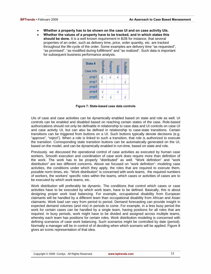
Further model advancement A state-based approach of case management will also offer nice possibilities to apply model-driven controls to case data and UI. Case data (properties) can be enabled on various aspects, of data control based on the state that the case has reached in its life-cycle. Properties can be atomic as well as complex. Document associations, as defined in the case meta-data, are considered properties as well. As shown in Figure 7, aspects of case data that can be controlled by state are e.g.:
• Whether a property is applicable: Certain properties might be applicable later, but are not yet relevant early in the case life-cycle.
• Whether a property is required: A property might be optional early in the case life-
cycle, but might be required in a later phase.
11 Copyright © 2009 Cordys. All Rights Reserved. www.bptrends.com
BPTrends ▪ February 2009 An Approach to Case Based Management
• Whether a property has to be shown on the case UI and on case activity UIs. • Whether the values of a property have to be tracked, and in which states this
should be done. It is a well known requirement in B2B for instance, that several properties of an order, such as delivery time, price, order quantity, etc. are tracked throughout the life-cycle of the order. Some examples are delivery time “as requested”, “as promised”, “as modified during fulfillment” and “as realized”. Such data is important for subsequent business performance analysis.
Figure 7: State-based case data controls
UIs of case and case activities can be dynamically enabled based on state and role as well. UI controls can be enabled and disabled based on reaching certain states of the case. Role-based authorizations should not only be definable in relationship to case data and UI controls on case UI and case activity UI, but can also be defined in relationship to case-state transitions. Certain transitions can be triggered from buttons on a UI. Such buttons typically denote decisions (e.g. “approve”, “reject”). When a role is linked to such a transition, that role is authorized to execute the transition. Corresponding state transition buttons can be automatically generated on the UI, based on the model, and can be dynamically enabled in run-time, based on state and role.
Previously. we discussed the operational control of case activities as executed by human case workers. Smooth execution and coordination of case work does require more than definition of the work. The work has to be properly “distributed” as well. “Work definition” and “work distribution” are two different concerns. Above we focused on “work definition”: modeling case activities, the conditions under which they apply, the roles that are required to execute them, possible norm times, etc. “Work distribution” is concerned with work teams, the required numbers of workers, the workers’ specific roles within the teams, which cases or activities of cases are to be executed by which work teams, etc.
Work distribution will preferably be dynamic. The conditions that control which cases or case activities have to be executed by which work team, have to be defined. Basically, this is about designing proper work load balancing. For example, occupational disability from European claimants will be handled by a different team than occupational disability from African and Asian claimants. Work load can vary from period to period. Demand forecasting can provide insight in expected demand volumes (and mix) in periods to come. For example, in a less busy period the work for certain cases can be handled by a single team, having positions for all roles that are required. In busy periods, work might have to be divided and assigned across multiple teams, whereby each team has positions for certain roles. Work distribution modeling is concerned with defining scenarios of case work balancing. Such scenarios might be controlled by date (period). Normally a manager will be in control of of deciding when which scenario will be applied. Figure 8 gives an iconic representation of that idea.

12 Copyright © 2009 Cordys. All Rights Reserved. www.bptrends.com
BPTrends ▪ February 2009 An Approach to Case Based Management
Figure 8: Alternative case work assignments
Sometimes a work balance can be defined per case model. Often case work shares commonality across different case models, and for purpose of proper balancing, case models can be grouped into families whereby work load balance scenarios are defined per family. Note that work distribution design should not be merged into work definition design, but should be kept separate. Work distribution design is more dynamic by nature. For example. changes in expected demand patterns might lead to changes in work distribution design, but will normally not impact work definition design. Creating a new revision of a work definition model, when there is no change in the work itself, would not be a proper practice.
Ultimately work distribution models could support concepts that are similar to “line balancing” in manufacturing. As line balancing provides the foundation for Lean Manufacturing, work load balancing of case work will provide the foundation of what is sometimes being referred to as “Lean Office” (see Tapping and Shuker (2003) and Tapping and Dunn (2006) for examples). A more detailed discussion of modeling for case work distribution will go beyond the scope and purpose of this document.
In this document (as well as the previous one) we have frequently drawn an analogy between case workers in administrative environments and shop workers on the shop floor. We will close the discussion by providing a last bit of evidence of the appropriateness of that analogy. ERP and MES do support scheduling and labor accounting for shop worker activities. The more advanced ERP systems also provide the means to balance shop work (“line balancing”). It can be expected that ultimately, case management automation, as an integral part of a Business Process Management Suite (BPMS), or even better, a Business Operations Platform (BOP), will become the basis for the balancing and scheduling of, and accounting for, knowledge worker activities. References [1] Aalst, Wil. M.P. van der, Weske, M. and Grünbauer, D., Case Handling: A New Paradigm for Business Process Support, 2003 http://is.tm.tue.nl/staff/wvdaalst/publications/p252.pdf
[2] Barnes, C. J., Dalgleish, G. F., Jared, G. E. M., Mei, H., and Swift, K. G., Assembly Oriented Design, 1999 http://www.hull.ac.uk/MAPP/sandpit/content/publications/full_papers/isatp99.pdf
[3] Doganov, K., Haralanova, C. and Lutfy, M., Legal Case Management for not-for-profit organizations, 2005 http://www.mirrorservice.org/sites/download.sourceforge.net/pub/sourceforge/l/le/legalcase/lcm_manual_en-0.6-pre4.pdf

13 Copyright © 2009 Cordys. All Rights Reserved. www.bptrends.com
BPTrends ▪ February 2009 An Approach to Case Based Management
[4] Goebl, W., Messner, K. J. and Schwarzer, B., Experiences in Introducing Workflow Management in a Large Insurance Group, 2001 (from IEEE)
[5] Rooze, E. J., Paapst, M. and Sombekke, J., eCase Management, An international study in judicial organizations, 2007 http://www.rechtspraak.nl/NR/rdonlyres/67AEE8E1-7A06-4E05-BB64-C64245D13049/0/84120052_eCaseManagement.pdf
[6] Schlenoff, C., Knutilla, A. and Ray, S., Unified Process Specification Language: Requirements for Modeling Process, NIST, 1996 http://www.mel.nist.gov/msidlibrary/doc/schlen96/req-paper.pdf
[7] Sly, D. and Gopinath, P., Practical Approach to solving Multi-objective Line Balancing Problem, 2006 http://www.proplanner.com/Documents/Support/LB/LBTechnical.pdf
[8] Tapping, D. and Dunn, A., Lean Office Demystified, Using the Power of the Toyota Production System in Your Administrative Areas, MCS Media, Inc., 2006
[9] Tapping, D. and Shuker, T., Value Stream Management for the Lean Office, Eight Steps to Planning, Mapping and Sustaining Lean Improvements in Administrative Areas, Productivity Press, New York, 2003
[10] Wong, K. Y., Okfalisa and Salim, N., A knowledge diagnostic system for product defects, 2005 http://conference.iproms.org/sites/conference.iproms.org/files/papers2007/93.pdf
-------
Author
Henk de Man is Research Director of Cordys. [email protected] , www.cordys.com
Related Documents