BUGSHIELD TM ROLL-UP SCREEN DOOR MODEL 5700 This Manual Covers Serial No. 06896 (=> 4-6-98), For Doors Prior Consult Factory. This manual to remain with the unit: Date Installed:____________________ PRINTED IN U.S.A. email: [email protected] Manual Part #: 39500150 Publication: AMEN00207 2020-07-06

Welcome message from author
This document is posted to help you gain knowledge. Please leave a comment to let me know what you think about it! Share it to your friends and learn new things together.
Transcript

BUGSHIELDTM
ROLL-UP SCREEN DOORMODEL 5700
PRINTED IN U.S.A. Publication No. 5700Jemail: [email protected] November 2014
This Manual Covers Serial No. 06896 (=> 4-6-98), For Doors Prior Consult Factory.
This manual to remain with the unit:Date Installed:____________________
BUGSHIELDTM
ROLL-UP SCREEN DOORMODEL 5700
PRINTED IN U.S.A. Publication No. 5700Jemail: [email protected] November 2014
This Manual Covers Serial No. 06896 (=> 4-6-98), For Doors Prior Consult Factory.
This manual to remain with the unit:Date Installed:____________________
BUGSHIELDTM
ROLL-UP SCREEN DOORMODEL 5700
PRINTED IN U.S.A. Publication No. 5700Jemail: [email protected] November 2014
This Manual Covers Serial No. 06896 (=> 4-6-98), For Doors Prior Consult Factory.
This manual to remain with the unit:Date Installed:____________________
Manual Part #: 39500150 Publication: AMEN00207 2020-07-06

2 Publication: AMEN00207 2020-07-06
TABLE OF CONTENTS
INSTALLATION INSTRUCTIONS . . . . . . . . . . . . . . . . . . . . . .3
IN-JAMB MOUNTING BRACKET INSTALLATION . . . . . . . . .4
IN-JAMB ROLLER TUBE INSTALLATION . . . . . . . . . . . . . . . .6
IN-JAMB CURTAIN INSTALLATION . . . . . . . . . . . . . . . . . . . .9
LIMIT SWITCH ADJUSTMENT . . . . . . . . . . . . . . . . . . . . . . .10
IN-JAMB TRACK INSTALLATION . . . . . . . . . . . . . . . . . . . . .11
FACE MOUNT INSTALLATION . . . . . . . . . . . . . . . . . . . . . .13
OVERHEAD MOUNT INSTALLATION . . . . . . . . . . . . . . . . . .14
MAINTENANCE / TROUBLESHOOTING . . . . . . . . . . . . . . .18
ELECTRICAL INSTALLATION . . . . . . . . . . . . . . . . . . . . . . .19
EXPLODED VIEW WITH PARTS LIST . . . . . . . . . . . . . . . . .20
ARCHITECTURAL DRAWINGS . . . . . . . . . . . . . . . . . . . . . .24
WARRANTY PAGE . . . . . . . . . . . . . . . . . . . . . . . . . . .last page
NOTICE TO USEROur mission is to “Improve Industrial Safety, Security andProductivity Worldwide through Quality and Innovation.”
Thank you for purchasing the BUGSHIELD™ screen door fromRITE-HITE DOORS, INC. The BUGSHIELD is designed to helpkeep birds and insects from entering through exterior doorwaysand loading docks. The dynamic roll-up feature providespassage of personnel and equipment while providing excellentenvironmental protection and airflow with several options: In-Jamb, Face and Overhead mounts.
This owner’s manual MUST be stored near the door.RITE-HITE DOORS, INC. reserves the right to modify theelectrical and architectural drawings in this manual as well asthe actual parts used on this product are subject tomanufacturing changes and may be different than shown in thismanual. Due to unique circumstances with varyingrequirements, separate prints may be included with the unit.This manual should be thoroughly read and understood beforebeginning the installation, operation or servicing of this door.The information contained in this manual will allow you tooperate and maintain the door in a manner which will insuremaximum life and trouble free operation. The serial # label foryour door is located on the side of the track.
Your local RITE-HITE DOORS, INC. Representative providesthe Planned Maintenance Program (P.M.P.) which can be fittedto your specific operation. If any procedures for the installation,operation or maintenance of the BUGSHIELD have been leftout of this manual or are not complete, contact RITE-HITEDOORS, INC. Technical Support at 1-563-589-2722.
RECOMMENDED TOOL LIST3/8" [10] Tap Drill Drill9/16" [14] Socket and Wrench Straight Screwdriver5/32" [4] Allen Wrench Phillips Screwdriver6' [1829] Level Pop Rivet Gun25' [7620] Tape Measure Hand GrinderUtility Knife Wire Strippers3/32" [2] Allen Wrench5/16" or 3/8" [8 or 10] Driver for Tek ScrewsSAFETY IDENTIFICATIONNOTE:
A Note is used to inform you of important installation,operation or maintenance information.
LOCKOUT/TAGOUT PROCEDURESThe Occupational Safety and Health Administration requires that, inaddition to posting safety warnings and barricading the work area, thepower supply has been locked in the OFF position or disconnected. Itis mandatory that an approved lockout device is utilized. An exampleof a lockout device is illustrated. The proper lockout procedurerequires that the person responsible for the repairs is the only personwho has the ability to remove the lockout device.
In addition to the lockout device, it is also a requirement to tag thepower control in a manner that will clearly note that repairs are underway and state who is responsible for the lockout condition. Tagoutdevices have to be constructed and printed so that exposure toweather conditions or wet and damplocations will not cause the tag todeteriorate or become unreadable.
RITE-HITE Corporation does notrecommend any particular lockout device,but recommends the utilization of anOSHA approved device (refer to OSHAregulation 1910.147). RITE-HITECorporation also recommends the reviewand implementation of an entire safetyprogram for the Control of HazardousEnergy (Lockout/Tagout). Theseregulations are available through OSHApublication 3120.
2 Pub. No. 5700J NOVEMBER 2014
BUGSHIELD™ Model 5700
PRODUCT INTRODUCTION
Danger indicates the presence of a hazard that willcause severe personal injury, death.
DANGER!
Warning indicates the presence of a hazard that cancause severe personal injury, death.
WARNING!
Caution indicates the presence of a hazard that will orcan cause minor personal injury, death.
CAUTION!
Notice communicates installation, operation, or maintenanceinformation that is safety related but not hazard related and
may cause equipment or property damage.
NOTICE
• Up to 40-50% airflow, with vinyl-coated polyester mesh.• Heavy-duty industrial materials.
• Manual or power roll-up.
• Variety of mesh colors available including custom colors(consult factory).
• Water-resistant Hypalon™ bottom seal.
SPECIAL FEATURES

Publication: AMEN00207 2020-07-06 3
It is important to verify the following basicinformation before starting with the installation.TO PREVENT DAMAGE TO CONTENTS, STORE DRYBETWEEN 40° AND 80° F. 1. Alternate dimensions in brackets are in
[millimeters].
2. Make sure that you are working at the correctlocation and that you have any required workpermits.
3. Inspect the site to make sure that there are nooverhead obstructions (sprinkler pipes, HVACsystems, electrical supply lines, etc.) that mightinterfere with the installation.
4. Detour material handling equipment during theinstallation.
5. Make sure that the electrician is ready to bring thecorrect electrical power supply to the door controlbox. Make sure that the correct electrical power issupplied (110VAC) to the door if powered option ischosen.
6. Make sure that the electrical power can be shut offwithout interfering with other plant operations.
7. Move the door crate as close to the opening aspossible.
8. In the case of multiple doors being installed, it isimperative to install the proper components with thematching door unit. The serial # for your door is ona label located on the side of the lower track,Figure 9.2.
9. Install optional equipment after verifying dooroperation.
NOTE: Electrical prints included in the parts supersede any prints included in this owners manual on Page 19. Always check for electrical prints.
10. If jamb is less than 6 1/2” [165] wide, a narrow In-Jamb bracket and track version is used.
** Reference right or left from inside the building, orthe same side that the door is mounted on.
DOOR JAMB
1. Measure Door Opening Width at the top (A).
2. Measure Door Opening Width at the floor (B).
3. Measure Door Opening Height at left side (C).
4. Measure Door Opening Height at right side (D).
5. Dimensions from Steps 1 - 4 should be within ± 1/2"[13] of the dimensions listed on the serial numberlabel. If the measurements do not agree, STOP!Contact your RITE-HITE DOORS, INC.representative.
6. Surface MUST be flat, smooth and collinear withopposite side (E).
7. Using a 6’ [1829] carpenter’s level (F), verify thatthe door jambs and header are plumb andperpendicular.
8. Using a laser level (G), place a mark where thelaser is sighted on each side of the jamb todetermine if the floor is level. Measure both sidesfrom floor to the mark and if the floor is not level towithin 1/8" [3], shim under the sideframe that will belocated on the “Low Side” (H) (greatestmeasurement) of the door opening.
For space clearance requirements, seeArchitectural drawings on Pages 24 - 27.
Pub. No. 5700J NOVEMBER 2014 3
BUGSHIELD™ Model 5700
INSTALLATION INSTRUCTIONS
Make sure to barricade the door opening on bothsides to prevent unauthorized use until the door has
been completely installed.
CAUTION ! ! !!
When working with electrical or electronic controls,make sure that the power source has been locked out
and tagged according to OSHA regulations andapproved local electrical codes.
DANGER !! !!
Insta
llatio
n In
struc
tion
s
A
B
DC
E
F
G
HIt is important to verify the door opening to the door sizebefore starting with the installation.
NOTICE
Figure 3.1

4 Publication: AMEN00207 2020-07-06
** Reference right or left from inside the building, orthe same side that the door is mounted on.
1. Determine drive (A) and non-drive (B) brackets bylooking at the “U” shaped bracket.
2. Manual (C) doors have two “U” shaped bracketsand powered (D) models will have only one “U”shaped bracket.
3. For a manual door, the wider groove is for the non-drive side roller bearing. The narrow groove is forthe drive side shaft. The drive spring is always onthe right hand side for manual doors.
4. If metal jamb, mount brackets using a 3/8" [10]tap/drill. Brackets may be welded in place as longas they are kept square. Only tack in place toomake sure everything fits.
5. On power doors, the “U” shaped bracket is on thenon-drive side for the roller bearing, and thebracket with the two tabs (L) goes on the drive sidefor the motor.
6. The motor can be either right or left hand mounteddepending on power location.
7. Mount the bracket so the motor cable exits the sidethat the switch will be mounted on. One motor drivebracket tab with two cap screws (K) (5/32" [4] allenwrench) will be loose to allow for the roller tube tobe installed. Loctite should be used on thesescrews.
8. Before placing roller tube into the brackets, verifythat the motor cord cover has been pre-installed.
9. Curtain centerline (E). Center the fork of thebracket on the centerline on the jamb.
10. The direction of the “L” shaped motor cable groove(F) on the bracket faces the inside (G) the buildingand indicates the direction the curtain will roll off thetube. Use shims if the jamb is not square.
11. Position long leg (H) of mounting bracket tight tothe lintel and toward outside (J) of building. Cornermay need to be rounded for welding
4 Pub. No. 5700J NOVEMBER 2014
BUGSHIELD™ Model 5700
IN-JAMB MOUNTING BRACKET INSTALLATION
‘X’
‘X’ ‘X’
‘X’
A
B
C
D
E
F
G
J
H
G
J
K
L
G J
Figure 4.1
Figure 4.2

Publication: AMEN00207 2020-07-06 5
1. Bracket centered (E) on jamb.
2. Track flush with outside of bracket (M).
3. Idle bracket (N).
4. Manual drive side bracket (O).
5. Power drive side bracket (P).
Pub. No. 5700J NOVEMBER 2014 5
BUGSHIELD™ Model 5700
NARROW IN-JAMB MOUNTING BRACKET INSTALLATION
G J
GJ
G
E
M M
ON P
Figure 4.3

6 Publication: AMEN00207 2020-07-06
1. Loosen the lock collar (Q) on the non-drive shaft.
2. To adjust, slide non-drive shaft (R) on the rollertube (S) and set in non-drive bracket (B). Tightenthe cap screw in the collar on the non-drive shaft to60 in./lbs [6.8 N-m].
3. Allen wrench (T).
4. Install the roller tube (S) by inserting the shaft withroller bearing (U) into the non-drive bracket.
6. During “Pre-tension” (W), install the drive sidewith the flat spot (V) on the end of the shaftfacing the floor.
7. Looking at the ratchet side end of the roller tube,rotate (X) the roller tube, (note label) (Y) 30revolutions for 9'-1" [2769] to 10' [3048] high door,28 revolutions for 8'-1" [2464] to 9' high door, and26 revolutions for 8' [2438] high or less door toapply pretension.
8. Carefully lift the shaft of the roller out of the drivebracket (AD) and rotate it 180° so that the flat spotfaces the ceiling (Z) to the “Post-tension” position(AE).
9. Try to position the hook and loop fastener on theroller tube to the front so the curtain can be easilyattached. Tighten the two 3/32" [2] allen headscrews (AA) to lock the roller assembly in place onthe drive end (AD) of the roller tube.
6 Pub. No. 5700J NOVEMBER 2014
BUGSHIELD™ Model 5700
IN-JAMB ROLLER TUBE INSTALLATION
Screw
If the roller tube pawls are not engaged and theroller tube is released during tensioning, an
un-controlled unwind will occur.
CAUTION ! ! !!
S
Q
T
U
G
J
G
J
G
J
S
B
R
V
W
X ZAB
AE
Head of fastener used to mount bracket to the wall,MUST BE kept to a minimum to avoid the curtain and
retention bars from catching.
NOTICEFigure 6.1 Figure 6.3
Figure 6.2

Publication: AMEN00207 2020-07-06 7 Pub. No. 5700J NOVEMBER 2014 7
BUGSHIELD™ Model 5700
IN-JAMB ROLLER TUBE INSTALLATIONIn
-Ja
mb
Bra
cke
ts
S
Y
AA
AB AC
AD
Figure 6.7
Figure 6.6
Figure 6.5
Figure 6.4

8 Publication: AMEN00207 2020-07-06
1. Install the motor (A) into the drive bracket (B) bypositioning the two 3/8" [10] diameter drive pins (C)into the holes of the drive bracket.
2. Make sure the limit adjustment screws (D) face thefloor and the electrical cord (E) is at the top.
3. Tighten the two 5/32" [4] allen screws (F) intoplace. Loctite should be used on these screws.
NOTE:
Motor has a screw fastened approximately 261/2” [673] from the drive end of the aluminumtube to hold it in place and prevent fromslipping out.
8 Pub. No. 5700J NOVEMBER 2014
BUGSHIELD™ Model 5700
IN-JAMB ROLLER TUBE INSTALLATIONA
B
D
E
F
C
Keep roller tube level with motor, as motor mayfall out and cause damage.
NOTICE
Figure 8.1

Publication: AMEN00207 2020-07-06 9
Track with serial # label (E).
Unroll and inspect the curtain for any defects.
Remove TURN-TITE, and lintel seals.
In-Jamb mount shown
Manual Model1. After the curtain (A) is attached, the pawl can be
disengaged to unlock the spring mechanism by unrollingthe roller tube 1/2 turn and slowly allow the curtain to rollonto the tube.
2. If curtain does not fully open, check for binding of thecurtain and/or wind bars (B) on the jamb or the mountingbrackets. If all is clear and more tension needs to beplaced on the spring. Pull the door using the handle (C)to the closed position, remove the curtain from the rollertube and slowly allow the spring to unwind. Followprocedure for winding spring and add a couple moreturns to the spring.
3. If door goes up too fast and needs to be slowed down.Pull the door to the closed position, remove the curtainfrom the roller tube and slowly allow the spring to unwind.Follow the procedure for winding spring and remove acouple turns from the spring.
4. After installation the BUGSHIELD logo should faceoutside and the roll stop faces the inside of the building.
5. Lock the curtain in place with the latch bar (D).
Powered Model1. Connect power per Wiring Diagram Page 19.
2. Power the motor in the closed direction until it reachesthe closed limit switch and stops.
3. Activate the switch so the door fully opens. If the doorstops short or over travels, adjust the open limit switch,Fig ure 10.1 & 10.2.
4. Run the door fully closed. The limit switch will need to beadjusted to account for the 1 1/2 curtain pre-wraps on theroller tube.
5. Cycle the door and adjust the limit switches until thecorrect curtain closed and opened positions are attained.
6. For adjustment of limit switches, refer to steps inAdjusting Motor Limits and Fig ures 10.1 & 10.2.
NOTES:Special care should be taken when installing the curtain onto the roller tube to insure that the curtainhangs straight (F).In-jamb model curtain rolls off the front of the roller tube,face and overhead models roll off the back of the tube.Center the curtain on the roller tube and fasten with thehook and loop fastener.
1. Door Opening Width (G).
2. Curtain Width = D.O.W. minus 2” [51] (H).
Pub. No. 5700J NOVEMBER 2014 9
BUGSHIELD™ Model 5700
IN-JAMB CURTAIN INSTALLATIONIn
-Jam
b T
ube/C
urta
in
F
H
GD
C
BA
E
Figure 9.1
Figure 9.3Figure 9.2
10 Publication: AMEN00207 2020-07-06
Right Hand View - Bottom looking up
1. Adjust the open limit by running the door to theclosed position and prying the curtain away fromthe limit screws to gain access.
2. If the curtain does not fully open, rotate the openlimit screw in the clockwise (+) direction until thedoor is at the proper elevation.
3. If the curtain overtravels, rotate the open limit screwin the counterclockwise (–) direction until the dooris at the proper elevation.
4. To adjust the closed limit, run the curtain down andadjust as shown.
5. If the curtain overtravels, rotate the close limitscrew in the counter-clockwise (-) direction until thedoor is at the proper elevation.
6. If the curtain does not fully close, rotate the closelimit screw in the clockwise (+) direction until thedoor is at the proper elevation.
Adjustment Screws For Reference:A = In-Jamb, RH - Open LimitA = In-Jamb, LH - Close LimitA = Face/OH, LH - Open LimitA = Face/OH, RH - Close Limit
B = In-Jamb, RH - Close Limit B = In-Jamb, LH - Open LimitB = Face/OH, LH - Close Limit B = Face/OH, RH - Open Limit
FRONT SIDE CLOSE DIRECTIONC = In-Jamb, RH DriveC = Face/Overhead, LH Drive
REAR SIDE CLOSE DIRECTIOND = In-Jamb, LH DriveD = Face/Overhead, RH Drive
NOTE:
If the motor is run for four consecutive minutes athermal trip may occur. The motor may need to beallowed to cool for one hour or more, depending ondoor size, temperature.
10 Pub. No. 5700J NOVEMBER 2014
BUGSHIELD™ Model 5700
LIMIT SWITCH ADJUSTMENT
A
B
C
D
Figure 10.2
Figure 10.1
Publication: AMEN00207 2020-07-06 11
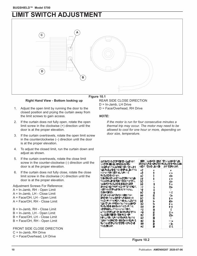
1. Route the motor cable (A) through the cable guardand along the groove in the bracket.
Drill angled hole through wall If needed.
2. Tracks are shipped precut and ready to install.Position the top of the track into the fork legs (B) onthe brackets and plumb the track. The track shouldbe fastened securely in place by tek screwingthrough the outermost flange every 2’–3' [51 - 76].
3. Inspect door jamb for obstructions such as dockseal mounting brackets, bolts. The jamb should beflat the full height of the jamb. If necessary the trackflange can be notched using a hacksaw.
1. If latch bar (A) catches or drags on tracks (B), cutno more than 1" [25] shorter. Grind ends smooth.
2. Verify latch bar properly seats into notch (C) intracks.
Pub. No. 5700J NOVEMBER 2014 11
BUGSHIELD™ Model 5700
IN-JAMB TRACK INSTALLATIONIn
-Jam
b M
oto
r
A
B
B
A
C
Do not notch into vertical U-channel of track.
NOTICE
Figure 11.1
Figure 11.2
12 Publication: AMEN00207 2020-07-06
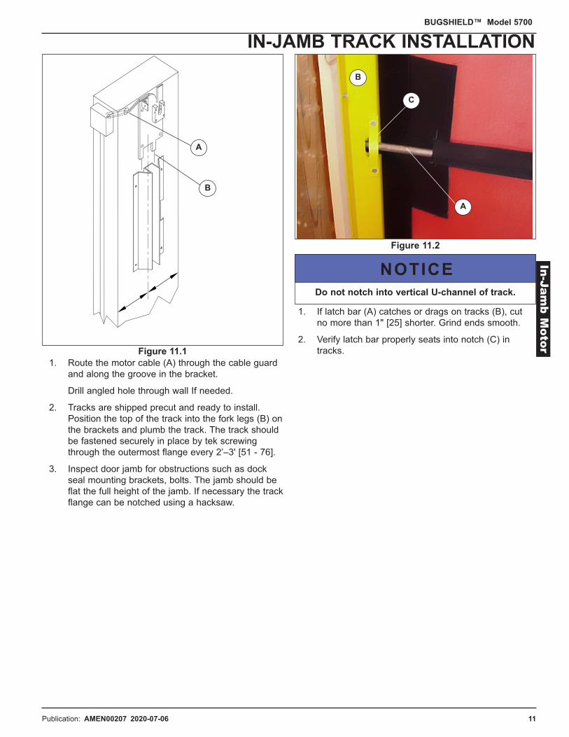
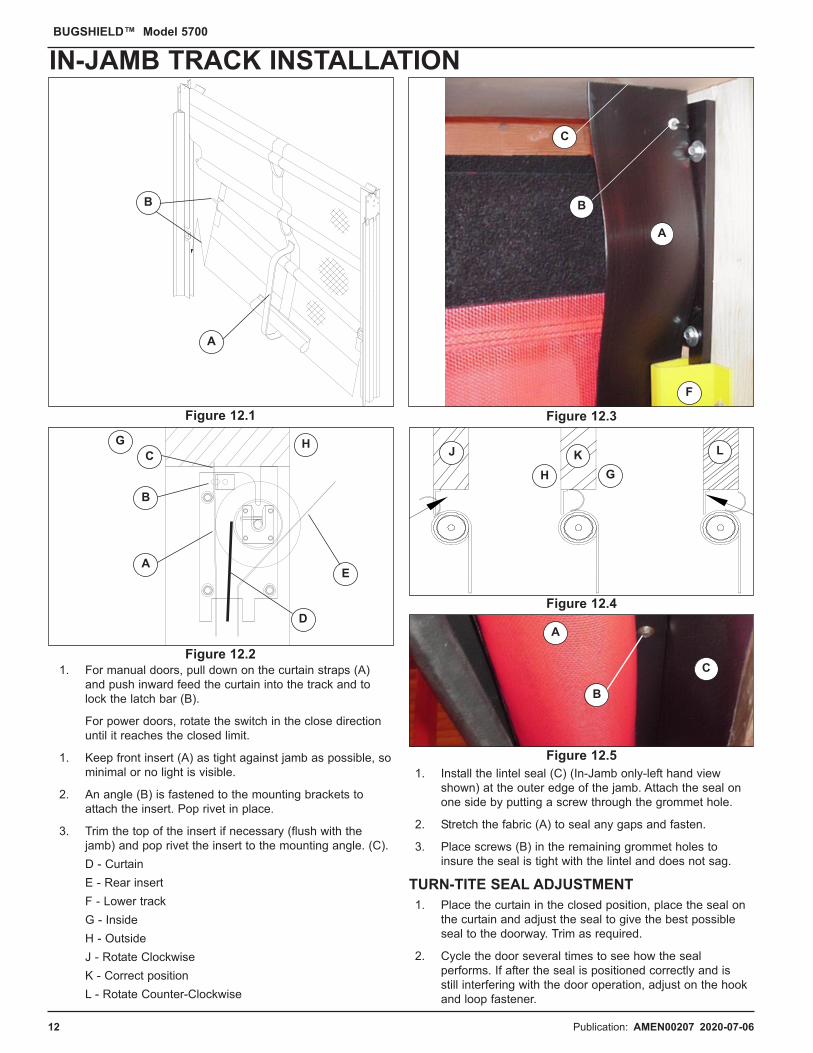
1. For manual doors, pull down on the curtain straps (A)and push inward feed the curtain into the track and tolock the latch bar (B).
For power doors, rotate the switch in the close directionuntil it reaches the closed limit.
1. Keep front insert (A) as tight against jamb as possible, sominimal or no light is visible.
2. An angle (B) is fastened to the mounting brackets toattach the insert. Pop rivet in place.
3. Trim the top of the insert if necessary (flush with thejamb) and pop rivet the insert to the mounting angle. (C).D - CurtainE - Rear insertF - Lower trackG - InsideH - OutsideJ - Rotate ClockwiseK - Correct positionL - Rotate Counter-Clockwise
1. Install the lintel seal (C) (In-Jamb only-left hand viewshown) at the outer edge of the jamb. Attach the seal onone side by putting a screw through the grommet hole.
2. Stretch the fabric (A) to seal any gaps and fasten.
3. Place screws (B) in the remaining grommet holes toinsure the seal is tight with the lintel and does not sag.
TURN-TITE SEAL ADJUSTMENT1. Place the curtain in the closed position, place the seal on
the curtain and adjust the seal to give the best possibleseal to the doorway. Trim as required.
2. Cycle the door several times to see how the sealperforms. If after the seal is positioned correctly and isstill interfering with the door operation, adjust on the hookand loop fastener.
12 Pub. No. 5700J NOVEMBER 2014
BUGSHIELD™ Model 5700
IN-JAMB TRACK INSTALLATION
A
A
B
C
B
A
B
CG H
E
D
A
C
B
F
H G
J K L
Figure 12.5
Figure 12.2
Figure 12.4
Figure 12.1 Figure 12.3

Publication: AMEN00207 2020-07-06 13
NOTE:See Page 3 for general installation instructions.
Refer throughout the manual for other instructions,including: adjusting limits, TURN-TITE seal and insert bracket.
A = Top View
B = Side ViewC = 1/2 O.D.W.D = Steel (H) = 1/2 O.D.W. + 2 1/4" [57].D = PVC (J) = 1/2 O.D.W. + 1 1/2" [38].M = Door Opening WidthN = Curtain Width = D.O.W. + 2” [51].
1. The drive and idle mounting brackets (E) are pre-installedat the factory onto the brackets. Remove the lower insidebolt and attach the brackets to the tracks (K). Level (L)and mount bracket/track assembly to the jamb.
2. Verify that the door opening height is correct. Measurefrom the high side of the jamb to locate the first bracket.The bracket will need to be mounted at D.O.H. plus 6 1/2"[165] (F) up from the floor to centerline of the bottommounting hole and D.O.H. plus 8" [203] (G) up tocenterline of the top hole. Shim so brackets are parallel toeach other.
3. Spring (A) is on the left hand side for manualface/overhead models. Powered unit may be either rightor left. Refer to In-Jamb instructions for installation,Pages 6 - 8.
4. Curtain rolls off the back (B) of the tube. Insert will needto be pulled under roller tube to install curtain.
Pub. No. 5700J NOVEMBER 2014 13
BUGSHIELD™ Model 5700
FACE MOUNT INSTALLATIONFace M
ount
A
B
A
BD
C
E
FG
H J
L
K
M
N
Figure 13.2
Figure 13.1

14 Publication: AMEN00207 2020-07-06
A = Dimension A (Door Opening Width)B = Overhead DoorC = Dimension CD = Top ViewE = Side ViewF = Door Opening HeightG = LevelH = O.D.H. Plus 6 1/2” [165]J = O.D.H. Plus 8” [203]K = 2 1/2” [64]T = Curtain Width = D.O.W. + 2” [51]Taken from Survey form.If Dim C - 5” < Dim A, door is built to Dim A.If C-5” => Dim A, door will be built to Dim C - 5”.NOTE:
See Page 3 for general installation instructions.
Refer throughout the manual for other instructions, including: adjusting limits, TURN-TITE seal and insert bracket.
1. Spring (L) is on the left hand side for manual face/overhead models. Powered unit may be either right or left. Refer to In-Jamb instructions for installation, Pages 6 - 8.
2. Remove the lower inside bolt (M) and attach the bracketsto the tracks loosely to allow for adjustment away fromthe over-head door. Level and mount bracket/trackassembly to the jamb.
3. Curtain rolls off the back of the tube (N). Insert will needto be pulled under roller tube to install curtain.
4. Adjust to go around over-head door tracks (P).
1. Replace thrust bearing (Q) if door is hard to raise, loweror is binding up.
2. Hub (R) and Flat Washers (S).
14 Pub. No. 5700J NOVEMBER 2014
BUGSHIELD™ Model 5700
OVER-HEAD MOUNT INSTALLATIONC
B
D
F
G
E
H
J
K
L
M
P
N
Q
S
R
A
T
Figure 14.2
Figure 14.1
Publication: AMEN00207 2020-07-06 15
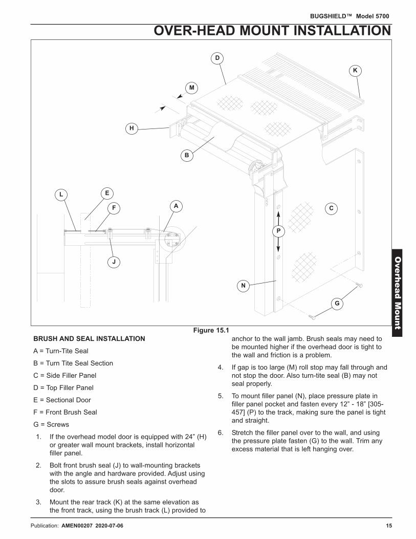
BRUSH AND SEAL INSTALLATION
A = Turn-Tite Seal
B = Turn Tite Seal Section
C = Side Filler Panel
D = Top Filler Panel
E = Sectional Door
F = Front Brush Seal
G = Screws
1. If the overhead model door is equipped with 24” (H)or greater wall mount brackets, install horizontalfiller panel.
2. Bolt front brush seal (J) to wall-mounting bracketswith the angle and hardware provided. Adjust usingthe slots to assure brush seals against overheaddoor.
3. Mount the rear track (K) at the same elevation asthe front track, using the brush track (L) provided to
anchor to the wall jamb. Brush seals may need tobe mounted higher if the overhead door is tight tothe wall and friction is a problem.
4. If gap is too large (M) roll stop may fall through andnot stop the door. Also turn-tite seal (B) may notseal properly.
5. To mount filler panel (N), place pressure plate infiller panel pocket and fasten every 12” - 18” [305-457] (P) to the track, making sure the panel is tightand straight.
6. Stretch the filler panel over to the wall, and usingthe pressure plate fasten (G) to the wall. Trim anyexcess material that is left hanging over.
Pub. No. 5700J NOVEMBER 2014 15
BUGSHIELD™ Model 5700
OVER-HEAD MOUNT INSTALLATIONO
verh
ead M
ount
A
B
C
D
F
E
G
J
H
K
L
M
N
P
Figure 15.1

16 Publication: AMEN00207 2020-07-06
1. It is the responsibility of the electrician to be sure alllocal, state, and national electrical codes are met.Codes may require the power cable to be run inrigid conduit.
2. All connections to the junction box must bethrough the bottom or side of the enclosure.
3. It is the responsibility of the buyer to provideelectrical service up to the junction box with properbranch service protection and an approved meansof disconnect.
4. The junction box is provided with class CCprotective fusing for the incoming power.
5. The incoming power terminals in the junction boxwill not accommodate wires larger than 10AWG.
6. Mount the open/close switch on a wall adjacent tothe door approximately 54" [1372] above the floorlevel.
7. The cable is provided from the junction box to theswitch, so mount junction box within 8' [2438] of themotor. Wire per schematic shown, Page 19.
SHEET METAL HOOD INSTALLATION (EXTERIOR FACE MOUNT ONLY)1. If no seal or shelter product is covering your
exterior mounted Bugshield, a sheet metal hoodshould be installed to keep the Bugshield free ofrain, snow, and the outside environment.
2. To mount hood, place on exterior surface ofbuilding, using the steel braces provided.
OPERATING PROCEDURE1. If the door is power operated, turn the knob on the
switch in the desired open or closed direction.
2. If the door is manually operated and is in the closedposition, grab the center latch bar handle, pull downslightly until the latch bar is out of the lockedposition and allow the door to raise while hangingonto the pull down strap until it reaches the openposition.
3. If the door is in the open position, grab the pulldown strap and pull down until the latch bar can befed into the locked position on the tracks.
16 Pub. No. 5700J NOVEMBER 2014
BUGSHIELD™ Model 5700
OPERATING PROCEDURE
When working with electrical or electronic controls,make sure that the power source has been locked out
and tagged according to OSHA regulations andapproved local electrical codes.
DANGER !! !!

Publication: AMEN00207 2020-07-06 17
This page intentionally left blank.
Pub. No. 5700J NOVEMBER 2014 17
RITE-HITE DOORS NOTES PAGEBUGSHIELD™ Model 5700

18 Publication: AMEN00207 2020-07-0618 Pub. No. 5700J NOVEMBER 2014
BUGSHIELD™ Model 5700
MAINTENANCE / TROUBLESHOOTING
DEFINITION FUNCTIONCurtain If the curtain becomes wedged or caught in the tracks, the FU1 fuse may blow due to over
current. Make sure the curtain is centered on the roller tube and tracks straight when rolling up or down. If the roller tube is not level the curtain will telescope and bind. If the curtain is blowingout of the tracks, check to make sure the tracks are not mounted too far apart. If the tracks are mounted too wide, the door will continue to blow out from the wind and the latch bar may not hold the curtain in place. Move tracks in to the correct distance per track installation instructions. To place curtain back into the tracks, insert one side of the curtain into the track and lift the other side up and slide into tracks.
Filler Panel (Overhead model only) The Overhead model is equipped with a side filler panel, that seals from the door track to the wall. Fasten the filler panel to the track with screws and then fasten to the wall using the pressure plates provided. Make sure panel is taught.
FU1 Fuse (Power model only) The FU1 Fuse protects motor damage from over voltage or high amp draw. Check wires for shorts or loose connections if the fuse is blowing. Check that curtain is not getting caught in tracks. The J-Box has a 6 Amp 600V CC time delayed fuse to protect the motor.
High Wind Condition The BugShield door should not be operated in a high wind condition as it may blow out of the tracks and cause damage.
Junction Box (Power model only) The Junction Box is standard on power operated doors and is supplied with an 8’ cord that runsfrom the J-Box to the Open/Close switch. The Junction box has terminals for incoming power, motor leads, and the open/close switch. The J-Box has a 6 Amp 600V CC time delayed fuse to protect the motor.
Limit Switches (Power model only) The limits are adjusted by turning the limit switch screws located on the end of the underside of the motor. DO NOT adjust the limit switches too far that they start to click. Turn no more than 24 revolutions in any one direction as the limit nut will be run off the lead screw and start to click. When this happens the door will continue to run in the same direction and not stop until a thermal trip occurs. When this occurs, the motor either needs to be replaced or taken apart and fixed. See Page 10 for limit switch adjustment procedures.
Lintel Seal (In-Jamb model only) The Lintel seal is attached to the jamb header, keeps the wind from blowing the Turn-Tite seal and prevents birds from building nests on the roller tube when the door is in the stored position.
Motor (Power model only) The motor is 110VAC single phase. The motor is encased inside the roller tube and is equipped with limit switches for open, closed positions and a 8’ [2438] power cord. If the motor is run for an extended period of time, the motor will heat up and a thermal trip will occur. The motor will need some time to allow the thermal sensor to cool down. Time may vary depending on door size and temperature. If the motor is running in the reverse direction, switch the wiring for the open/close button, per Bugshield electrical drawing. Motor draws 4.2 service amps.
Open/Close Switch (Power only) The open/close switch is a constant pressure switch that is used to open and close the door. If the switch is released during door travel, the door will stop immediately and the direction can becontinued or reversed.
Roller Tube The roller tube is equipped with an adjustable non-drive shaft. To adjust, loosen the allen head screwand slide the shaft in or out to the correct length and tighten the allen head screw.
Spring (Manual model only) The correct number of turns on the spring is located on the label on the roller tube. If the door ishard to lift, make sure the curtain slides freely in the tracks and around the roller tube. If the door is still hard to lift, increase spring tension. Make sure to oil or grease spring to reduce friction on the coils.
Turn-Tite Seal The Turn-Tite seal must be trimmed in the field to accommodate the jamb. Fasten to the curtain using the hook and loop fastener. The Turn-Tite seal covers the gap between the roller tube and the jamb.
RITE-HITE DOORS® PLANNED MAINTENANCEModel 5700 BUGSHIELD™
CUSTOMER:RHC# SERIAL# DATE:
Periodic Check:Planned Maintenance
CurtainInsertsLimit Switches (powered only)Lintel SealMotorNon - Drive BearingSpringSwitch - Junction BoxTracks/Roller
Turn - Tite SealWindbars
Recommended P.M. Intervals(Time Shown In Months)
1
•
•
Inspect and Perform the Following (See Manual)
Clean, perform visual inspection, look for tears.Inspect for wear and replace as necessary.Check open and close positions.Perform visual inspection.Run door.Inspect for wear or binding.Test for ease of open and close. Lubricate.Clean and check wire connections (with power off).Perform visual inspection, check for proper widthdimension and tighten all bolts.Adjust as required in the closed position.Remove and straighten if required.
4•••••
••
•
8 12•••••••••
••
18
•
•
•
24•••••••••
••
30 36•••••••••
••

Publication: AMEN00207 2020-07-06 19 Pub. No. 5700J NOVEMBER 2014 19
BUGSHIELD™ Model 5700
WIRING DIAGRAME
lec
trical D
raw
ing
Tro
uble
shootin
g

20 Publication: AMEN00207 2020-07-0620 Pub. No. 5700J NOVEMBER 2014
BUGSHIELD™ Model 5700
IN-JAMB FRAME SERVICE PARTSNOT SHOWN: 41,68
61
5960
18
1752
64
42
37
2535
19
67
38
5750
5820
52
16
26
40
27
688281513
66659
1110688
66659
1412
39
56

Publication: AMEN00207 2020-07-06 21 Pub. No. 5700J NOVEMBER 2014 21
BUGSHIELD™ Model 5700
FACE & OVERHEAD SERVICE PARTSE
xp
lode
d P
arts L
ist
688
253519
67
61
64
42
59
18
17 37
5820
16
2640
27
1110
39
56
24
7
5750
60
45 46 47
29
34
24
62
69
51
21
30
31
36
70
41
63 71
8
66659
66659
2322
60
38
32 33

22 Publication: AMEN00207 2020-07-0622 Pub. No. 5700J NOVEMBER 2014
BUGSHIELD™ Model 5700
SERVICE PARTS LISTITEM QTY DESCRIPTION P/N
7 1 Seal, Ass’y, Brush (Overhead Only) 6850....8 1 Track Assembly 7351....9 2 Track Insert, (part of track with hardware) 5310….
10 1 Roller Tube Weldment 6730….11 1 Roller Tube Ass’y, Manual w / spring 6731….11 1 Roller Tube Ass’y, Power w / motor 6731….12 1 Kit, Bracket, In-Jamb, Manual and Power Idle 5370008713 1 Kit, Bracket, In-Jamb, Manual Drive 5370008214 1 Kit, Bracket, In-Jamb, Narrow (Manual/Power Idle) 5370008815 1 Kit, Bracket, Narrow In-Jamb, Manual Drive 5370008316 1 Bracket, Mount Idle 1450024917 1 Shaft, Spring Drive 6895009618 1 Spring Ass’y, > 3' 6" to <= 5' 6" - 22” 5370006918 1 Spring Ass’y, > 5' 6" to <= 7' 10" - 44” 5370007018 1 Spring Ass’y, > 7' 10" and Over - 67” 5370007119 1 Motor x 120V Kit 5370040920 1 Adapter, Drive Side, Manual 1030000621 2/4 Bracket, Brush Seal Mounting 14500107
(2-Overhead Only, 4 if Dim “J” > 10.5”)22 1 Kit, Bracket, Face Idle 5.5 (Includes #16) 5370008423 1 Kit, Bracket, Overhead, 16", Idle (Inclds #16) 5370008523 1 Kit, Bracket, Overhead, 24", Idle (Inclds #16) 5370008624 1 Bracket, Brush Seal 1453....25 2 Tab, Motor Mounting (Powered Only) 7274002526 1 Bearing, Ball, 1/2" x 1-1/8" x 3/8" 1250001227 1 Ring, Spiral Retaining, 1/2" 6702002528 1 Kit, Bracket, In-Jamb, Power (Drive) 5370009228 1 Kit, Bracket, Narrow In-Jamb, Power (Drive) 5370009329 1 Kit, Bracket, Face, Power 5370008929 1 Kit, Bracket, Overhead, Power, 16" 5370009029 1 Kit, Bracket, Overhead, Power, 24" 5370009130 a/r Cable, 16/7, PVC Jacket 1565015431 1 Switch, Cam, with Enclosure 7270014432 1 Junction Box Assembly 5353000933 1 Fuse, 6.25 AMP, 250V, 3AG, Time Delay 5100001734 1 Fuse, Holder 5100001935 1 Guard, Cable (Powered Only) 5130001536 1 Filler Panel (Overhead Only) 6346....37 1 Plate, Motor Mount 6500014438 1 Wheel, Drive 7555001439 4 Screw, Flathead Allen, 1/4-20 x 3/4" 67860069
ITEM QTY DESCRIPTION P/N40 A/R 2" Hook PSA (Touch and Hold Fastener) 7400002041 1 Sheet Metal Hood 5283....42 1 Bracket, Mount, Manual Drive 1450020843 1 Kit, Electrical (includes J-box, switch & cable) 5370010444 1 Kit, 5700, Patch, 10x10 Mesh, Black 5370057444 1 Kit, 5700, Patch, 20x30 Mesh, Black 5370057544 1 Kit, 5700, Patch, 20x30 Mesh, Grey 5370057644 1 Kit, 5700, Patch, 17x11 Mesh, Grey 5370057744 1 Kit, 5700, Patch, 17x11 Mesh, Green 5370057844 1 Kit, 5700, Patch, 17x11 Mesh, Red 5370057944 1 Kit, 5700, Patch, 17x11 Mesh, Blue 5370058044 1 Kit, 5700, Patch, 17x11 Mesh, Yellow 5370058145 1 Kit, Bracket, Face, Manual Drive 5370007946 1 Kit, Bracket, Overhead, 16" Manual Drive 5370008047 1 Kit, Bracket, Overhead, 24" Manual Drive 5370008148 -49 -50 1 Kit, Thrust Bearing for Roller Tube Spring 53700308
(manual doors only)51 a/r Pressure Strip 1/8” x 1” x 8’ (OH mount only) 1012000152 2 Insert Bracket Mount (In-Jamb only) 1450021953 -54 1 Flat Washer-Bronze 7416000755 -56 2 Washer, Flat, .50 x .88 7415001457 1 Thrust Bearing 1/2” ID x 7/8” OD 1250002458 1 Screw SHCS, 1/4-20 x 1 1/2” Gr 8 6786000559 1 Washer Flat, 1/4” x 3/4” x 1/16” 7411000160 1 Top Filler Panel (Dim “J” > 10.5” only) 6346....61 1 Screw, FHMS, Socket, 5/16-18 x 1” Self Locking 6787009362 a/r Tek Screw w/Washer 6785011363 2 Bracket, Floor, FC/OH, 5700 1450022264 1 Kit, Hub Drive (includes hub, catches & hdw) 5370039265 1/1 Kit, 5700, Insert, < 10’ W/HDW 5370010566 1/1 Kit, 5700, Insert, > 10’ W/HDW 5370010667 1 Bushing, Tube Support 1555005368 a/r Wind Support Kit (not shown) 5370042369 a/r Plate, Top,F/OH,Steel Track 6500013870 1 Kit, Switch, JBox, Cable, 5700 5370048471 a/r Rivet, 2pc, LF, 1/4 x 1 3/8" GRP, BLK, BLM 66860005

Publication: AMEN00207 2020-07-06 23 Pub. No. 5700J NOVEMBER 2014 23
BUGSHIELD™ Model 5700
CURTAIN SERVICE PARTS
ITEM QTY DESCRIPTION P/N1 1 Curtain, Fabricated without windbars 2830....2 1 Curtain, Assembled with Windbars 2831....3 a/r Pipe, Wind Bar Small 6442....
Face, O/H = O.D.W. + 7/8”In Jamb = O.D.W. - 3 1/8”)
4 a/r *Pipe, Wind Bar Large 6442....Face, O/H = O.D.W. + 1 3/8”In Jamb = O.D.W. - 2 5/8”)
5 1 Pipe, Latchbar, Manual Only 6443....6 1 Pipe, Bottom Bar 6445....7 1 Seal, TURN-TITE 6846....
ITEM QTY DESCRIPTION P/N8 1 Seal, Lintel, In-Jamb Only 6847....9 1 Handle, Long 45 1/2” 53700109
For manual doors D.O.H. =>9’-0”10 1 Handle, Long 35 1/2” 53700108
For manual doors D.O.H. <9’-0”11 1 Curtain, Roll Stop, Manual Only 72050007
Must Include P/N 53700040 (8)
* Large Wind Bars are used for Power Operated => 10’-3” Height &Width
21
3
4
11
8
7
6
5
109

24 Publication: AMEN00207 2020-07-0624 Pub. No. 5700J NOVEMBER 2014
BUGSHIELD™ Model 5700
IN-JAMB MOUNT ARCHITECTURAL

Publication: AMEN00207 2020-07-06 25 Pub. No. 5700J NOVEMBER 2014 25
IN-JAMB NARROW MOUNT ARCHITECTURALBUGSHIELD™ Model 5700
Arc
hite
ctu
ral D
raw
ing
s

26 Publication: AMEN00207 2020-07-0626 Pub. No. 5700J NOVEMBER 2014
FACE MOUNT ARCHITECTURALBUGSHIELD™ Model 5700
Pub. No. 5700J NOVEMBER 2014 27
OVER-HEAD MOUNT ARCHITECTURALBUGSHIELD™ Model 5700
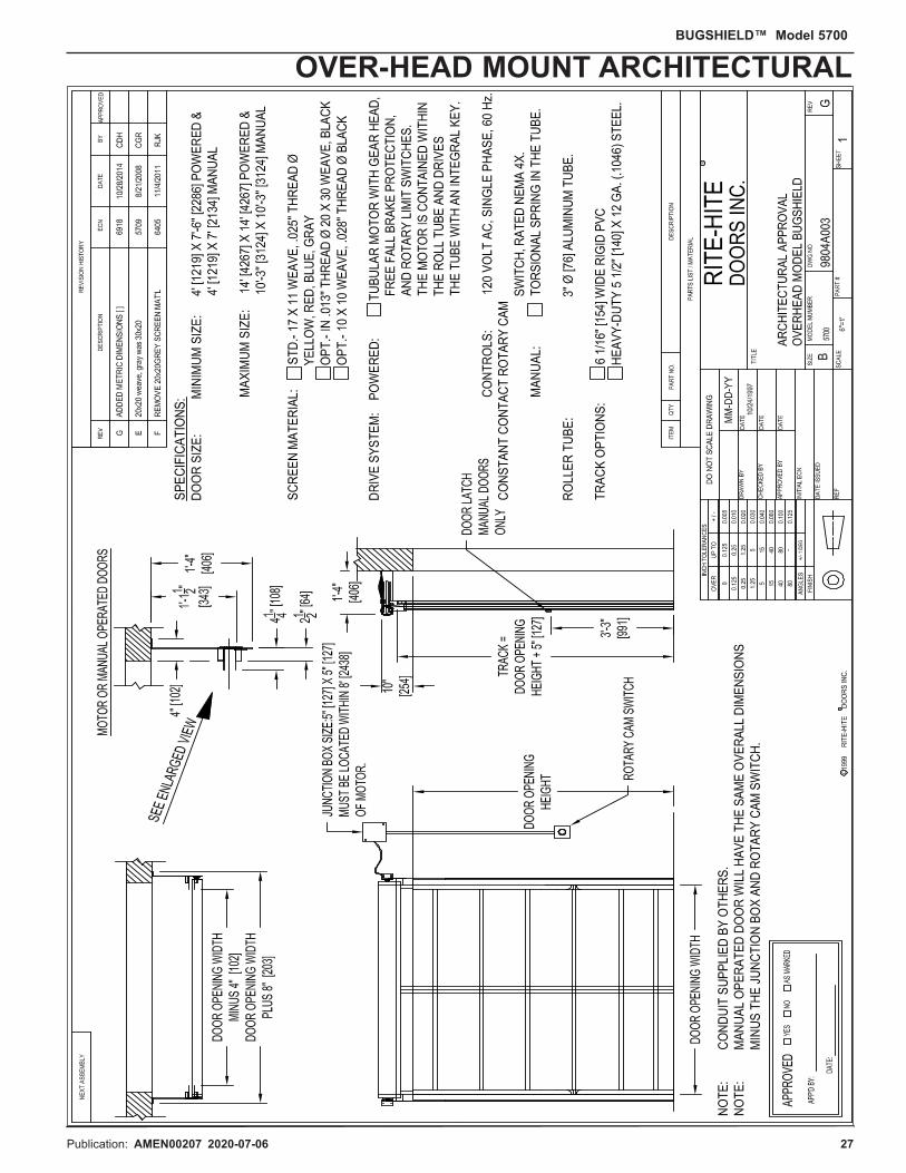
Publication: AMEN00207 2020-07-06 27 Pub. No. 5700J NOVEMBER 2014 27
OVER-HEAD MOUNT ARCHITECTURALBUGSHIELD™ Model 5700

28 Publication: AMEN00207 2020-07-06
LIMITED WARRANTYRITE-HITE Company, LLC and its affiliates (collectively “RITE-HITE”) warrants that the BUGSHIELD door sold to the Owner will be free ofdefects in design, materials and workmanship (ordinary wear and tear excepted) for the periods set forth below (“Limited Warranty”).
One (1) Year on all mechanical and ninety (90) days electrical parts.
One (1) Year labor, based on approved travel and labor repair times.
Maximum cycles of forty (40) per day.
REMEDIES
Parts. RITE-HITE’s obligations under this Limited Warranty is limited to repairing or replacing, at RITE-HITE’s option, any part which isdetermined by RITE-HITE to be defective during the applicable warranty period. Such repair or replacement shall be RITE-HITE’s soleobligation and the Owner’s exclusive remedy under this Limited Warranty.
Labor. RITE-HITE will provide warranty service without charge for labor in the first year of the warranty period. Thereafter, a charge willapply to any repair or replacement under this Limited Warranty.
CLAIMS. Claims under this Limited Warranty must be made (i) within 30 (thirty) days after discovery and (ii) prior to expiration of theapplicable warranty period. Claims shall be made in writing or by contacting the representative from whom the Product was purchaseddirectly. Owner must allow RITE-HITE or its agent, a reasonable opportunity to inspect any Product claimed to be defective and shall, atRITE-HITE’s option, either (x) grant RITE-HITE or its agent access to Owner’s premises for the purpose of repairing or replacing the Productor (y) return of the Product to the RITE-HITE, f.o.b. RITE-HITE’s factory.
NOT WARRANTED. RITE-HITE does not warrant against and is not responsible for wear items such as fuses, batteries, bulbs, vision andseals. No implied warranty shall be deemed to cover, damages that result directly or indirectly from: (i) the unauthorized modification orrepair of the Product, (ii) damage due to misuse, neglect, accident, failure to provide necessary maintenance, or normal wear and tear of theProduct, (iii) failure to follow RITE-HITE’s instructions for installation, failure to operate the Product within the Product’s rated capacitiesand/or specified design parameters, or failure to properly maintain the Product, (iv) use of the Product in a manner that is inconsistent withRITE-HITE’s guidelines or local building codes, (v) movement, settling, distortion, or collapse of the ground, or of improvements to which theProducts are affixed, (vi) fire, flood, earthquake, elements of nature or acts of God, riots, civil disorder, war, or any other cause beyond thereasonable control of RITE-HITE, (vii) improper handling, storage, abuse, or neglect of the Product by Owner or by any third party.
DISCLAIMERS. THIS LIMITED WARRANTY IS EXCLUSIVE AND IN LIEU OF ALL OTHER REPRESENTATIONS AND WARRANTIES,EXPRESS OR IMPLIED, AND RITE-HITE EXPRESSLY DISCLAIMS AND EXCLUDES ANY IMPLIED WARRANTIES OFMERCHANTABILITY OR FITNESS FOR PURPOSE. RITE-HITE SHALL NOT BE SUBJECT TO ANY OTHER OBLIGATIONS ORLIABILITIES, WHETHER ARISING OUT OF BREACH OF CONTRACT, WARRANTY, TORT (INCLUDING NEGLIGENCE AND STRICTLIABILITY) OR OTHER THEORIES OF LAW, WITH RESPECT TO THE PRODUCTS SOLD OR SERVICES RENDERED BY RITE-HITE,OR ANY UNDERTAKINGS, ACTS, OR OMISSIONS RELATING THERETO.
LIMITATION OF LIABILITY. IN NO EVENT SHALL RITE-HITE BE RESPONSIBLE FOR, OR LIABLE TO ANYONE FOR, SPECIAL,INDIRECT, COLLATERAL, PUNITIVE, INCIDENTAL, OR CONSEQUENTIAL DAMAGES, EVEN IF RITE-HITE HAS BEEN ADVISED OFTHE POSSIBILITY OF SUCH DAMAGES. Such excluded damages include, but are not limited to, personal injury, damage to property, lossof goodwill, loss of profits, loss of use, cost of cover with any substitute product, interruption of business, or other similar indirect financialloss. Rite-Hite 2.1.14
RITE-HITE DOORS, INC. is covered by one or more of the following U.S. patents, including patents applied for, pending, or issued:
5,579,820, 5,638,883, 5,794,678, 5,887,385, 5,915,448, 5,944,086, 6,089,305, 6,145,571, 6,148,897, 6,192,960, 6,212,826, 6,321,822,6,325,195, 6,330,763, 6,360,487, 6,481,487, 6,560,927, 6,598,648, 6,612,357, 6,615,898, 6,688,374, 6,698,490, 6,837,296, 6,901,703,6,942,000, 6,964,289, 7,034,682, 7,045,764, 7,111,661, 7,114,753, 7,151,450, 7,578,097, 7,699,089, 7,748,431, 7,757,437, 8,037,921,8,167,020, 8113265.
RITE-HITE®, RITE-HITE® DOORS, FASTRAX®, FASTRAX® FR, FASTRAX® FRLD, FASTRAX® CL, LITESPEED™, SPLITSECOND™,TRAKLINE™, BUG-SHIELD™, ISO-TEK®, BARRIER® GLIDER, DOK-DOR™ are trademarks of RITE-HITE®.
RITE-HITE8900 N. Arbon Drive
P.O. Box 245020Milwaukee, Wisconsin 53224-9520
Sales: 414-355-2600Toll Free: 800-456-0600
Aftermarket: 414-362-3714Service: 563-589-2722
Service Fax: 563-589-2737Representatives in All Major Cities
www.ritehite.com
28 Pub. No. 5700J NOVEMBER 2014
RITE-HITE DOOR PRODUCT WARRANTYBUGSHIELD™ Model 5700
Related Documents