ROBOGUARD ™ FIXED FENCING SAFETY BARRIER PRINTED IN U.S.A. Publication No. RBGRDC email: [email protected] January 2015 This Manual Covers All Units Shipped to Date. This manual to remain with the unit: Date Installed:____________________

Welcome message from author
This document is posted to help you gain knowledge. Please leave a comment to let me know what you think about it! Share it to your friends and learn new things together.
Transcript
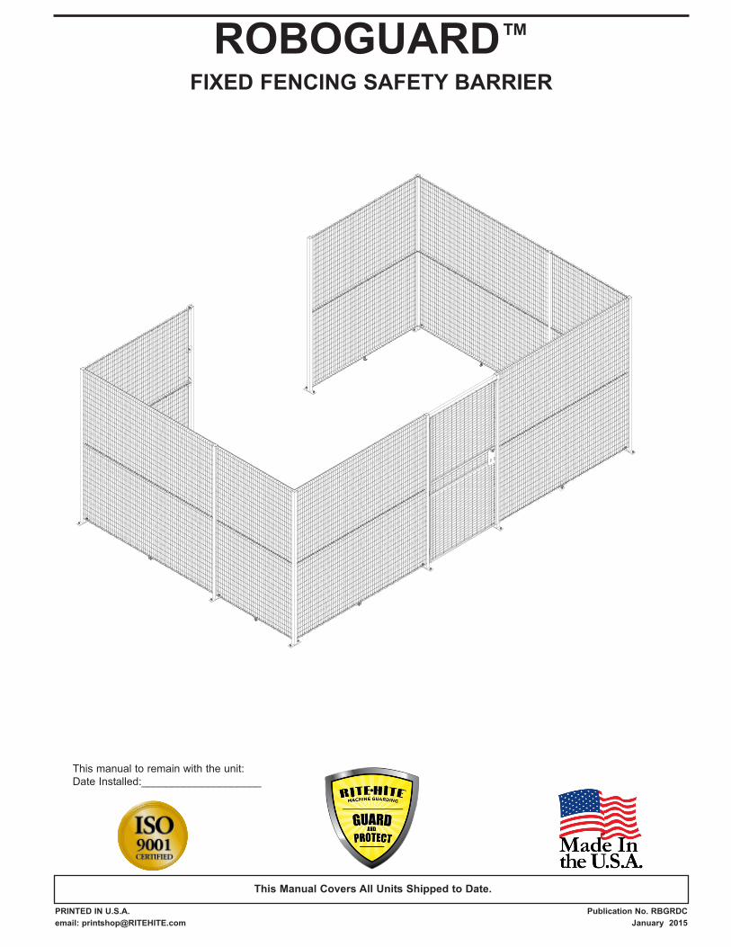
ROBOGUARD™
FIXED FENCING SAFETY BARRIER
PRINTED IN U.S.A. Publication No. RBGRDC
email: [email protected] January 2015
This Manual Covers All Units Shipped to Date.
This manual to remain with the unit:
Date Installed:____________________
2 Pub. No. RBGRDC JANUARY 2015
ROBOGUARD™
CHAPTER 1
INSTALLATION INSTRUCTIONS . . . . . . . . . . . . . . . . . . . . . .3
CHAPTER 2
SERVICE PARTS . . . . . . . . . . . . . . . . . . . . . . . . . . . . . . . . . . .8
ARCHITECTURAL DRAWINGS . . . . . . . . . . . . . . . . . . . . . . .9
WARRANTY . . . . . . . . . . . . . . . . . . . . . . . . . . . . . . . back page
NOTICE TO END USER
Our mission is to “Improve Industrial Safety, Security
and Productivity Worldwide Through Quality and
Innovation.”
Thank you for purchasing the ROBOGUARD™ by RITE-
HITE® MACHINE GUARDING. The ROBOGUARD
provides an effective safety barrier against physical
contact with the machine by the operator.
This owner’s manual should be thoroughly read and
understood before beginning the installation, operation or
servicing of this unit. This owner’s manual MUST be
stored near the unit.
Only RITE-HITE MACHINE GUARDING authorized parts
are to be used on this product. Failure to do so may void
warranty.
RITE-HITE MACHINE GUARDING reserves the right to
modify the architectural drawings in this manual as well
as the actual parts used on this product are subject to
manufacturing changes and may be different than shown
in this manual. Due to unique circumstances with varying
requirements, separate prints may be included with the
unit.
The information contained in this manual will allow you to
operate and maintain the unit in a manner which will
insure maximum life and trouble free operation.
Your local RITE-HITE MACHINE GUARDING
Representative provides the Planned Maintenance
Program (P.M.P.) which can be fitted to your specific
operation.
Before returning any parts, you must contact the RITE-
HITE MACHINE GUARDING Technical Support group to
obtain authorization and a PO#, as parts will not be
accepted without a PO#.
If any procedures for the installation, operation or
maintenance of the ROBOGUARD have been left out of
this manual, are not complete or have suggestions,
contact RITE-HITE MACHINE GUARDING Technical
Support at 1-563-589-2722.
TOOLS & MATERIAL REQUIRED
9/16” [14] Open End or Ratchet Wrench and socket
5/16” [8] Driver Bit For Drill
Hammer & Cordless Drill (3/8” or 1/2”) [10-13] w/Phillips Bit
3/8” [10] Masonry Bits
Tape Measure 25’ Minimum
Chalk Line
6’ [1829] Carpenters Level
Hammer
8’ [2438] Step Ladder
Hardware for mounting the unit, shimming and anchoringto the floor are not provided.
PRELIMINARY INSTRUCTIONS
What location will I be working at ?
Is there anything buried in the floor where the anchors go ?
Does the installation allow for clearance for other
operations ?
Are any special work permits required?
Are there any overhead obstructions?
How will the work area be barricaded?
Plan the installation so that it will not interfere with work
processes.
CHAPTER 1 - INTRODUCTION
Galvanized or painted black.
Custom sizes up to 8’ [2438] tall fencing.
Sectional design allows for greater flexibility.
Standard lock and optional interlock or window.
SPECIAL FEATURES
Pub. No. RBGRDC JANUARY 2015 3
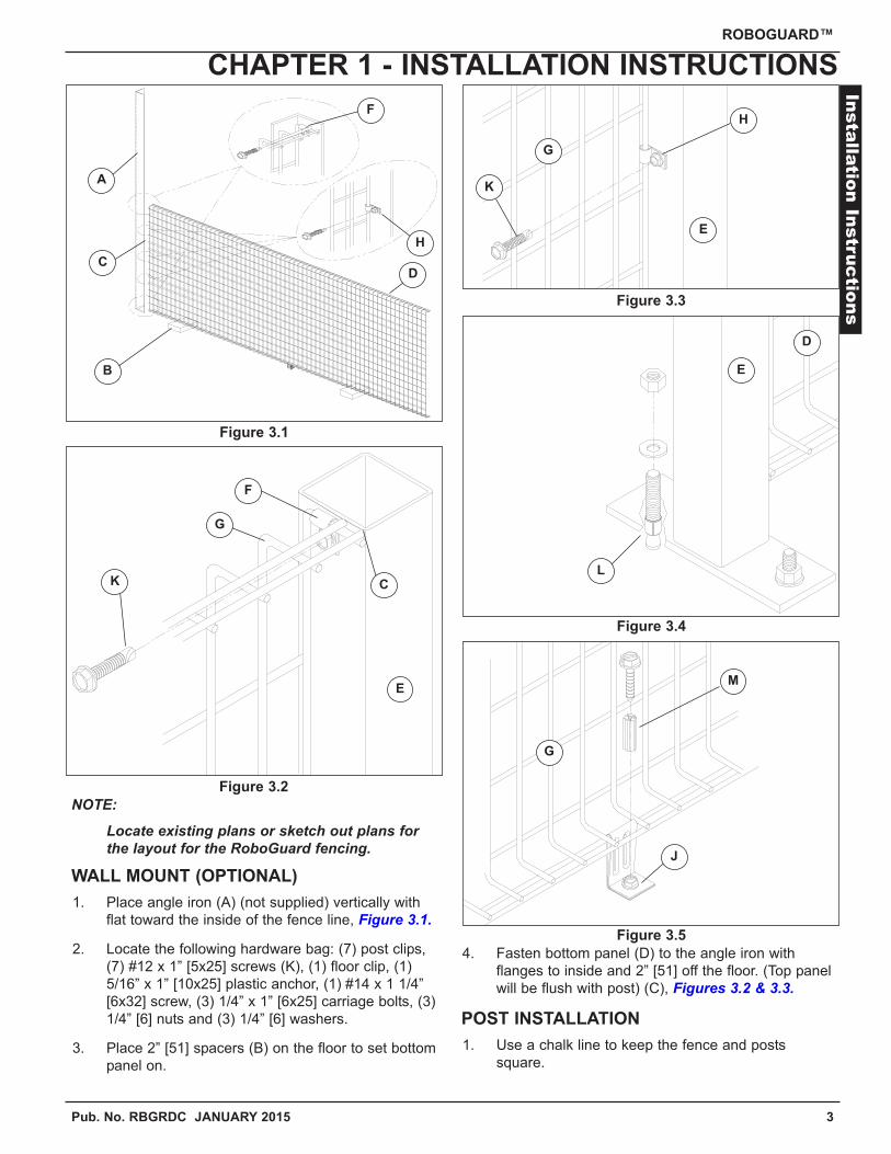
NOTE:
Locate existing plans or sketch out plans for the layout for the RoboGuard fencing.
WALL MOUNT (OPTIONAL)
1. Place angle iron (A) (not supplied) vertically with
flat toward the inside of the fence line, Figure 3.1.
2. Locate the following hardware bag: (7) post clips,
(7) #12 x 1” [5x25] screws (K), (1) floor clip, (1)
5/16” x 1” [10x25] plastic anchor, (1) #14 x 1 1/4”
[6x32] screw, (3) 1/4” x 1” [6x25] carriage bolts, (3)
1/4” [6] nuts and (3) 1/4” [6] washers.
3. Place 2” [51] spacers (B) on the floor to set bottom
panel on.
4. Fasten bottom panel (D) to the angle iron with
flanges to inside and 2” [51] off the floor. (Top panel
will be flush with post) (C), Figures 3.2 & 3.3.
POST INSTALLATION
1. Use a chalk line to keep the fence and posts
square.
ROBOGUARD™
CHAPTER 1 - INSTALLATION INSTRUCTIONSIn
stalla
tion In
structio
nsFigure 3.3
Figure 3.2
Figure 3.1
Figure 3.5
Figure 3.4
A
B
CD
C
E
E
D
F
G
G
E
G
H
J
K
L
M
H
F
K
4 Pub. No. ROBOGUARDC JANUARY 2015
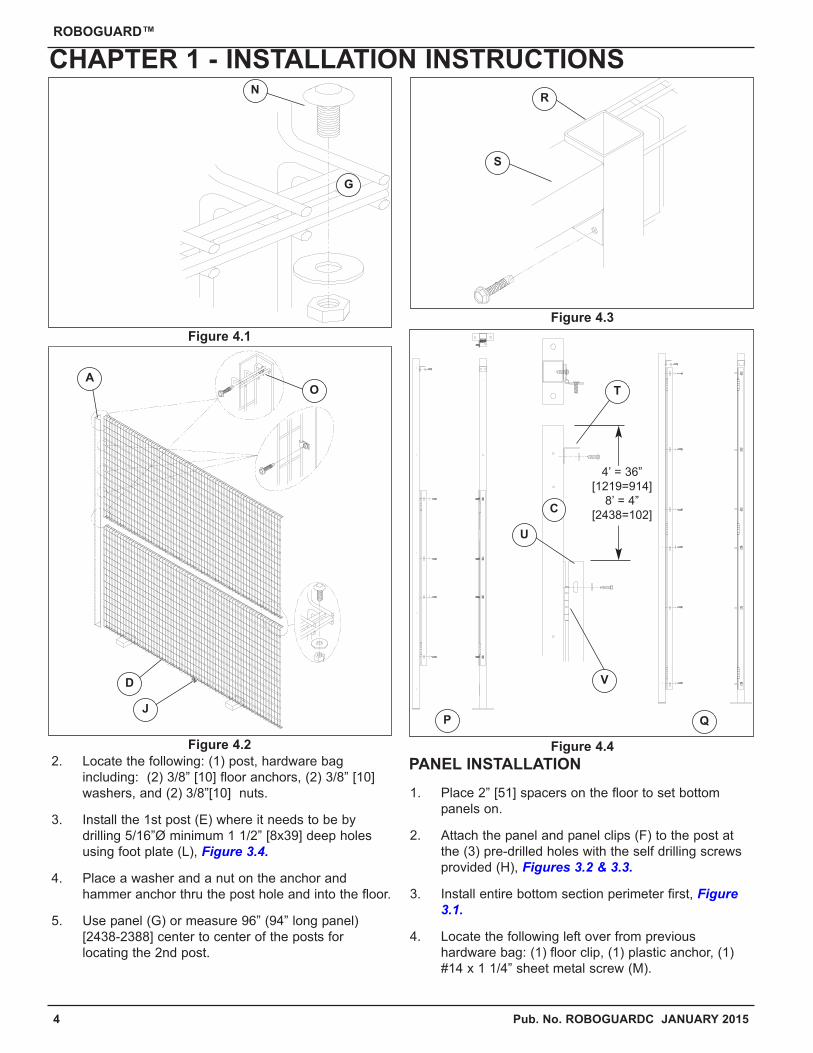
2. Locate the following: (1) post, hardware bag
including: (2) 3/8” [10] floor anchors, (2) 3/8” [10]
washers, and (2) 3/8”[10] nuts.
3. Install the 1st post (E) where it needs to be by
drilling 5/16”Ø minimum 1 1/2” [8x39] deep holes
using foot plate (L), Figure 3.4.
4. Place a washer and a nut on the anchor and
hammer anchor thru the post hole and into the floor.
5. Use panel (G) or measure 96” (94” long panel)
[2438-2388] center to center of the posts for
locating the 2nd post.
PANEL INSTALLATION
1. Place 2” [51] spacers on the floor to set bottom
panels on.
2. Attach the panel and panel clips (F) to the post at
the (3) pre-drilled holes with the self drilling screws
provided (H), Figures 3.2 & 3.3.
3. Install entire bottom section perimeter first, Figure3.1.
4. Locate the following left over from previous
hardware bag: (1) floor clip, (1) plastic anchor, (1)
#14 x 1 1/4” sheet metal screw (M).
ROBOGUARD™
CHAPTER 1 - INSTALLATION INSTRUCTIONS
4’ = 36”
[1219=914]
8’ = 4”
[2438=102]
Figure 4.1
Figure 4.3
Figure 4.2 Figure 4.4
G
A
N
O
D
J
C
QP
V
U
S
R
T
Pub. No. RBGRDC JANUARY 2015 5
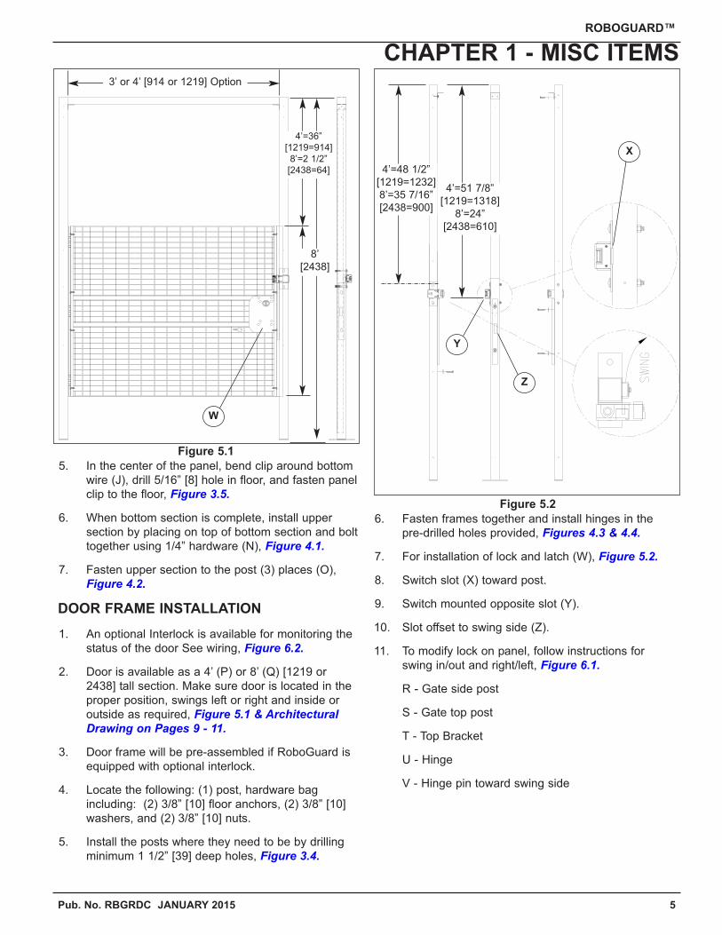
5. In the center of the panel, bend clip around bottom
wire (J), drill 5/16” [8] hole in floor, and fasten panel
clip to the floor, Figure 3.5.
6. When bottom section is complete, install upper
section by placing on top of bottom section and bolt
together using 1/4” hardware (N), Figure 4.1.
7. Fasten upper section to the post (3) places (O),
Figure 4.2.
DOOR FRAME INSTALLATION
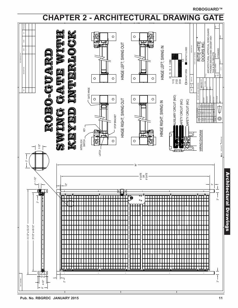
1. An optional Interlock is available for monitoring the
status of the door See wiring, Figure 6.2.
2. Door is available as a 4’ (P) or 8’ (Q) [1219 or
2438] tall section. Make sure door is located in the
proper position, swings left or right and inside or
outside as required, Figure 5.1 & ArchitecturalDrawing on Pages 9 - 11.
3. Door frame will be pre-assembled if RoboGuard is
equipped with optional interlock.
4. Locate the following: (1) post, hardware bag
including: (2) 3/8” [10] floor anchors, (2) 3/8” [10]
washers, and (2) 3/8” [10] nuts.
5. Install the posts where they need to be by drilling
minimum 1 1/2” [39] deep holes, Figure 3.4.
6. Fasten frames together and install hinges in the
pre-drilled holes provided, Figures 4.3 & 4.4.
7. For installation of lock and latch (W), Figure 5.2.
8. Switch slot (X) toward post.
9. Switch mounted opposite slot (Y).
10. Slot offset to swing side (Z).
11. To modify lock on panel, follow instructions for
swing in/out and right/left, Figure 6.1.
R - Gate side post
S - Gate top post
T - Top Bracket
U - Hinge
V - Hinge pin toward swing side
ROBOGUARD™
CHAPTER 1 - MISC ITEMS3’ or 4’ [914 or 1219] Option
4’=36”
[1219=914]
8’=2 1/2”
[2438=64] 4’=48 1/2”
[1219=1232]
8’=35 7/16”
[2438=900]
4’=51 7/8”
[1219=1318]
8’=24”
[2438=610]
8’
[2438]
W
Figure 5.1
Figure 5.2
X
Y
Z
6 Pub. No. RBGRDC JANUARY 2015
ROBOGUARD™
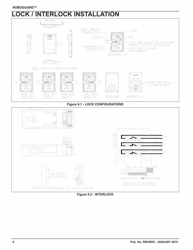
LOCK / INTERLOCK INSTALLATION
Figure 6.1 - LOCK CONFIGURATIONS
Figure 6.2 - INTERLOCK
Pub. No. RBGRDC JANUARY 2015 7
ROBOGUARD™
This page intentional left blank.
NOTES PAGE
8 Pub. No. RBGRDC JANUARY 2015
ROBOGUARD™
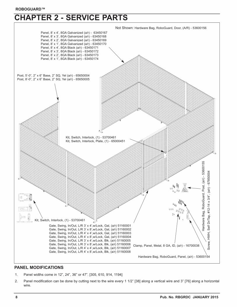
CHAPTER 2 - SERVICE PARTS
PANEL MODIFICATIONS
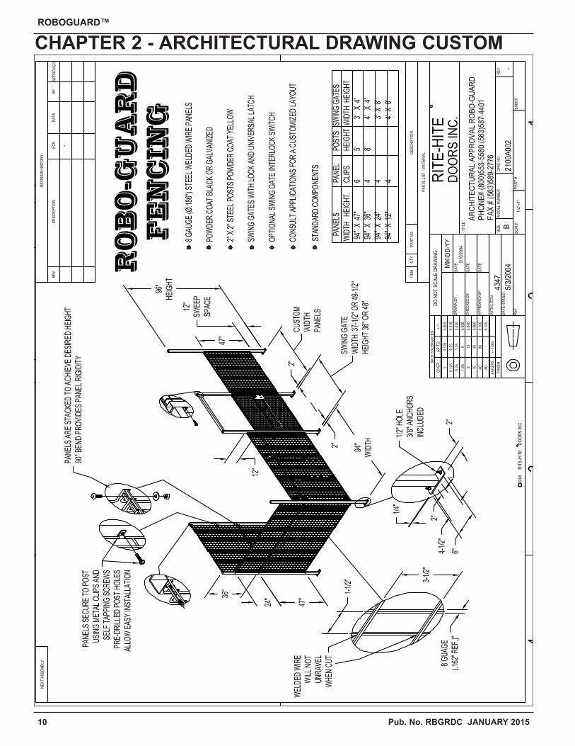
1. Panel widths come in 12”, 24”, 36” or 47”. [305, 610, 914, 1194]
2. Panel modification can be done by cutting next to the wire every 1 1/2” [38] along a vertical wire and 3” [76] along a horizontal
wire.
Panel, 8’ x 4’, 8GA Galvanized (a/r) - 63450167
Panel, 8’ x 3’, 8GA Galvanized (a/r) - 63450168
Panel, 8’ x 2’, 8GA Galvanized (a/r) - 63450169
Panel, 8’ x 1’, 8GA Galvanized (a/r) - 63450170
Panel, 8’ x 4’, 8GA Black (a/r) - 63450171
Panel, 8’ x 3’, 8GA Black (a/r) - 63450172
Panel, 8’ x 2’, 8GA Black (a/r) - 63450173
Panel, 8’ x 1’, 8GA Black (a/r) - 63450174
Post, 5’-0”, 2” x 6” Base, 2” SQ, Yel (a/r) - 65650004
Post, 8’-0”, 2” x 6” Base, 2” SQ, Yel (a/r) - 65650005
Not Shown: Hardware Bag, RoboGuard, Door, (A/R) - 53600156
Kit, Switch, Interlock, (1) - 53700461
Kit, Switch, Interlock, (1) - 53700461
Kit, Switch, Interlock, Plate, (1) - 65000451
Gate, Swing, In/Out, L/R 3’ x 4’,w/Lock, Gal, (a/r) 51160001
Gate, Swing, In/Out, L/R 3’ x 8’,w/Lock, Gal, (a/r) 51160002
Gate, Swing, In/Out, L/R 4’ x 4’,w/Lock, Gal, (a/r) 51160003
Gate, Swing, In/Out, L/R 4’ x 8’,w/Lock, Gal, (a/r) 51160004
Gate, Swing, In/Out, L/R 3’ x 4’,w/Lock, Blk, (a/r) 51160005
Gate, Swing, In/Out, L/R 3’ x 8’,w/Lock, Blk, (a/r) 51160006
Gate, Swing, In/Out, L/R 4’ x 4’,w/Lock, Blk, (a/r) 51160007
Gate, Swing, In/Out, L/R 4’ x 8’,w/Lock, Blk, (a/r) 51160008
Scre
w,
HW
H,
Self D
r/Tap,
#12-1
4 x
3/4
”, (
a/r
) -
67850004
Hardware Bag, RoboGuard, Panel, (a/r) - 53600154
Clamp, Panel, Metal, 8 GA, ID, (a/r) - 16700038
Hard
ware
Bag,
RoboG
uard
, P
ost, (
a/r
) -
53600155

Pub. No. RBGRDC JANUARY 2015 9
ROBOGUARD™
CHAPTER 2 - ARCHITECTURAL DRAWING STANDARDS
ervic
e P
arts
10 Pub. No. RBGRDC JANUARY 2015
ROBOGUARD™
CHAPTER 2 - ARCHITECTURAL DRAWING CUSTOM
Pub. No. RBGRDC JANUARY 2015 11
ROBOGUARD™
CHAPTER 2 - ARCHITECTURAL DRAWING GATEA
rchite
ctu
ral D
raw
ings
LIMITED WARRANTYRITE-HITE Company, LLC and its affiliates (collectively “RITE-HITE”) warrants that the RoboGuard product sold to the Owner will be free of defectsin design, materials and workmanship (ordinary wear and tear excepted) for the periods set forth below (“Limited Warranty”).
One (1) Year on all mechanical and electrical parts.
REMEDIES
Parts. RITE-HITE’s obligations under this Limited Warranty is limited to repairing or replacing, at RITE-HITE’s option, any part which is determinedby RITE-HITE to be defective during the applicable warranty period. Such repair or replacement shall be RITE-HITE’s sole obligation and theOwner’s exclusive remedy under this Limited Warranty.
CLAIMS. Claims under this Limited Warranty must be made (i) within 30 (thirty) days after discovery and (ii) prior to expiration of the applicablewarranty period. Claims shall be made in writing or by contacting the representative from whom the Product was purchased directly. Owner mustallow RITE-HITE or its agent, a reasonable opportunity to inspect any Product claimed to be defective and shall, at RITE-HITE’s option, either (x)grant RITE-HITE or its agent access to Owner’s premises for the purpose of repairing or replacing the Product or (y) return of the Product to theRITE-HITE, f.o.b. RITE-HITE’s factory.
NOT WARRANTED. RITE-HITE does not warrant against and is not responsible for wear items such as fuses, batteries, bulbs, vision and seals.No implied warranty shall be deemed to cover, damages that result directly or indirectly from: (i) the unauthorized modification or repair of theProduct, (ii) damage due to misuse, neglect, accident, failure to provide necessary maintenance, or normal wear and tear of the Product, (iii) failureto follow RITE-HITE’s instructions for installation, failure to operate the Product within the Product’s rated capacities and/or specified designparameters, or failure to properly maintain the Product, (iv) use of the Product in a manner that is inconsistent with RITE-HITE’s guidelines or localbuilding codes, (v) movement, settling, distortion, or collapse of the ground, or of improvements to which the Products are affixed, (vi) fire, flood,earthquake, elements of nature or acts of God, riots, civil disorder, war, or any other cause beyond the reasonable control of RITE-HITE, (vii)improper handling, storage, abuse, or neglect of the Product by Owner or by any third party.
DISCLAIMERS. THIS LIMITED WARRANTY IS EXCLUSIVE AND IN LIEU OF ALL OTHER REPRESENTATIONS AND WARRANTIES, EXPRESSOR IMPLIED, AND RITE-HITE EXPRESSLY DISCLAIMS AND EXCLUDES ANY IMPLIED WARRANTIES OF MERCHANTABILITY OR FITNESSFOR PURPOSE. RITE-HITE SHALL NOT BE SUBJECT TO ANY OTHER OBLIGATIONS OR LIABILITIES, WHETHER ARISING OUT OF BREACHOF CONTRACT, WARRANTY, TORT (INCLUDING NEGLIGENCE AND STRICT LIABILITY) OR OTHER THEORIES OF LAW, WITH RESPECT TOTHE PRODUCTS SOLD OR SERVICES RENDERED BY RITE-HITE, OR ANY UNDERTAKINGS, ACTS, OR OMISSIONS RELATING THERETO.
LIMITATION OF LIABILITY. IN NO EVENT SHALL RITE-HITE BE RESPONSIBLE FOR, OR LIABLE TO ANYONE FOR, SPECIAL, INDIRECT,COLLATERAL, PUNITIVE, INCIDENTAL, OR CONSEQUENTIAL DAMAGES, EVEN IF RITE-HITE HAS BEEN ADVISED OF THE POSSIBILITY OFSUCH DAMAGES. Such excluded damages include, but are not limited to, personal injury, damage to property, loss of goodwill, loss of profits, lossof use, cost of cover with any substitute product, interruption of business, or other similar indirect financial loss. Rite-Hite 2.1.14
RITE-HITE DOORS, INC. is covered by one or more of the following U.S. patents, including patents applied for, pending, or issued:
5,579,820, 5,638,883, 5,794,678, 5,887,385, 5,915,448, 5,944,086, 6,089,305, 6,145,571, 6,148,897, 6,192,960, 6,212,826, 6,321,822, 6,325,195,6,330,763, 6,360,487, 6,481,487, 6,560,927, 6,598,648, 6,612,357, 6,615,898, 6,688,374, 6,698,490, 6,837,296, 6,901,703, 6,942,000, 6,964,289,7,034,682, 7,045,764, 7,111,661, 7,114,753, 7,151,450, 7,578,097, 7,699,089, 7,748,431, 7,757,437, 8,037,921, 8,167,020, 8,113,265.
RITE-HITE®, RITE-HITE® DOORS, RITE-HITE® MACHINE GUARDING, DEFENDER™, FLASHFOLD™, VERTIGUARD™, SLIDEAIR™,ROLLSHILED™, ROLLTOP™, ROBOGUARD™ and XTEN™ are trademarks of RITE-HITE®.
RITE-HITE MACHINE GUARDING
4343 Chavenelle Drive
P.O. Box 1200
Dubuque, Iowa 52002-2654
Toll Free Sales: 800-553-5560
Sales: 563-589-4401
Sales Fax: 563-589-2776
Service: 563-589-2722
Service Fax: 563-589-2737
Representatives in All Major Cities
www.ritehite.com/machineguard
www.ritehite.com
12 Pub. No. RBGRDC JANUARY 2015
RITE-HITE MACHINE GUARDING WARRANTY
ROBOGUARD™
Related Documents


