✬ ✫ ✩ ✪ FREE SPACE OPTICAL NETWORKING WITH VISIBLE LIGHT: A MULTI-HOP MULTI-ACCESS SOLUTION ZEYU WU Dissertation submitted in partial fulfillment of the requirements for the degree of Doctor of Philosophy BOSTON UNIVERSITY

Welcome message from author
This document is posted to help you gain knowledge. Please leave a comment to let me know what you think about it! Share it to your friends and learn new things together.
Transcript

'
&
$
%
FREE SPACE OPTICAL NETWORKING
WITH VISIBLE LIGHT:
A MULTI-HOP MULTI-ACCESS SOLUTION
ZEYU WU
Dissertation submitted in partial fulfillment
of the requirements for the degree of
Doctor of Philosophy
BOSTON
UNIVERSITY


BOSTON UNIVERSITY
COLLEGE OF ENGINEERING
Dissertation
FREE SPACE OPTICAL NETWORKING
WITH VISIBLE LIGHT:
A MULTI-HOP MULTI-ACCESS SOLUTION
by
ZEYU WU
B.S., Huazhong University of Science and Technology, 2003M.S., University of New Orleans, 2006
Submitted in partial fulfillment of the
requirements for the degree of
Doctor of Philosophy
2012
Approved by
First Reader
Thomas D.C. Little, PhDProfessor of Electrical and Computer Engineering
Second Reader
Jeffrey Carruthers, PhDAssociate Professor of Electrical and Computer Engineering
Third Reader
Murat Alanyali, PhDAssociate Professor of Electrical and Computer Engineering
Fourth Reader
Mona Mostafa Hella, PhDAssociate Professor of Electrical, Computer and Systems Engi-neering, Rensselaer Polytechnic Institute

Nothing in life is to be feared, it is only to be understood.Now is the time to understand more,so that we may fear less. Marie Curie

Acknowledgments
I would like to thank my advisor, Professor Thomas Little, for introducing me into
Visible Light Communication, a frontier wireless technology. I am very grateful to
him about giving me opportunities to explore the challenges and guiding me carving
out my research topics. I want to thank him for the moral and financial support and
the confidence bestowed in me.
I also want to thank Professor Jeffrey Carruthers. His broad knowledge and
experience on wireless optical communication provide me with great helps throughout
my research. This brings me to thank Professor Murat Alanyali and Professor Mona
Mostafa Hella for spending their precious time on helping me with my dissertation.
Then, I would like to thank all my old and new friends for the love and support
during these five years’ life in the beautiful Boston. Especially Jimmy Chau, Michael
Rahaim and Tarik Borogovac who share their knowledge and wisdom on my research.
My final gratitude goes to my family. There is no words in the world could fully
express my appreciation for the love and support from my mom and dad. I love you.
This work was supported primarily by the Engineering Research Centers Program
of the National Science Foundation under NSF Cooperative Agreement No. EEC-
0812056.
iv

FREE SPACE OPTICAL NETWORKING
WITH VISIBLE LIGHT:
A MULTI-HOP MULTI-ACCESS SOLUTION
(Order No. )
ZEYU WU
Boston University, College of Engineering, 2012
Major Professor: Thomas Little, PhD,Professor of Electrical and Computer Engineering
ABSTRACT
Wireless communication is currently dominated by Radio Frequency (RF) tech-
nologies. However, constraints, such as limited bandwidth and electromagnetic in-
terference, limit applications of RF technologies in certain scenarios. For example,
RF signals can cause interference with aircraft communication or medical devices in
airports or hospitals. Meanwhile, recent developments in solid-state Light-Emitting
Diode (LED) materials and devices are driving a resurgence into the use of Free-Space
Optical (FSO) wireless communication. Many opportunities exist to exploit low-cost
nature of LEDs and lighting units for widespread deployment of optical communica-
tion. However, some characteristics of the optical medium, including directionality
and susceptibility to visible light noise sources, must be managed.
In this dissertation, a model for indoor Visible Light Communication (VLC) ap-
plications is provided to analyze and predict the signal attenuation, Signal-to-Noise
Ratio (SNR), Bit Error Rate (BER) and data rate. Discrete Multi-tone (DMT)
v

modulation is discussed for optical signaling and analysis shows that although DMT
requires good SNR, it can provide 4 to 5 times the channel capacity of simple mod-
ulation schemes such as On-Off Keying (OOK). We propose an original solution for
indoor applications that achieves continuous 10 Mb/s data rates while supporting
multiple access under Non Line-of-Sight (LOS) condition. Analysis and simulation
of the two protocols under the hexagonal transceiver configuration indicate suitabil-
ity for high data rate communications between peers or multiple devices using the
peer-to-host mode. Furthermore, a novel Medium Access Control (MAC) scheme is
proposed in order to solve the contention among mobile receivers due to signal direc-
tionality, provide continuous connectivity and meet the expectation of low complexity
and low cost. Performance analysis shows more than 50 % improvement on latency
at the expense of a 6 % drop on system throughput.
vi

Contents
1 Introduction 1
1.1 A Brief History . . . . . . . . . . . . . . . . . . . . . . . . . . . . . . 1
1.2 Characteristics Comparison . . . . . . . . . . . . . . . . . . . . . . . 2
1.2.1 Advantages of FSO . . . . . . . . . . . . . . . . . . . . . . . . 2
1.2.2 Visible Light FSO . . . . . . . . . . . . . . . . . . . . . . . . . 3
1.2.3 Limitations and Problems . . . . . . . . . . . . . . . . . . . . 5
1.3 Dissertation Outline . . . . . . . . . . . . . . . . . . . . . . . . . . . 7
1.3.1 Contributions . . . . . . . . . . . . . . . . . . . . . . . . . . . 7
1.3.2 Organization . . . . . . . . . . . . . . . . . . . . . . . . . . . 9
2 Wireless Optical Communications 11
2.1 Background . . . . . . . . . . . . . . . . . . . . . . . . . . . . . . . . 11
2.1.1 Regulations and Standards . . . . . . . . . . . . . . . . . . . . 11
2.1.2 Link Topologies . . . . . . . . . . . . . . . . . . . . . . . . . . 14
2.1.3 Modulation Schemes . . . . . . . . . . . . . . . . . . . . . . . 21
2.1.4 Channel Model . . . . . . . . . . . . . . . . . . . . . . . . . . 23
2.1.5 Multi-Input Multi-Output . . . . . . . . . . . . . . . . . . . . 27
2.1.6 Direct Sequence Spread Spectrum . . . . . . . . . . . . . . . . 29
2.2 Related Works . . . . . . . . . . . . . . . . . . . . . . . . . . . . . . . 30
2.2.1 Prototypes . . . . . . . . . . . . . . . . . . . . . . . . . . . . . 31
2.2.2 Other Research Groups . . . . . . . . . . . . . . . . . . . . . . 40
vii

3 Modeling and Signaling of Indoor VLC 43
3.1 Framework for Indoor Scenarios . . . . . . . . . . . . . . . . . . . . . 43
3.1.1 Room Geometry . . . . . . . . . . . . . . . . . . . . . . . . . 43
3.1.2 Optical Power Analysis of LED Transmitter . . . . . . . . . . 45
3.1.3 LED and Photodiode Parameters . . . . . . . . . . . . . . . . 47
3.2 Channel Signal Attenuation Model . . . . . . . . . . . . . . . . . . . 48
3.2.1 Signal Attenuation . . . . . . . . . . . . . . . . . . . . . . . . 48
3.2.2 SNR . . . . . . . . . . . . . . . . . . . . . . . . . . . . . . . . 50
3.2.3 Upper Bound of the Rate . . . . . . . . . . . . . . . . . . . . 50
3.2.4 BER . . . . . . . . . . . . . . . . . . . . . . . . . . . . . . . . 51
3.2.5 Performance Analysis . . . . . . . . . . . . . . . . . . . . . . . 51
3.2.6 New VLC Prototype . . . . . . . . . . . . . . . . . . . . . . . 53
3.3 DMT Analysis . . . . . . . . . . . . . . . . . . . . . . . . . . . . . . . 54
3.3.1 BER . . . . . . . . . . . . . . . . . . . . . . . . . . . . . . . . 57
3.3.2 Channel Capacity . . . . . . . . . . . . . . . . . . . . . . . . . 61
3.4 Summary . . . . . . . . . . . . . . . . . . . . . . . . . . . . . . . . . 67
4 Multi-hop Multi-access VLC Solution 68
4.1 Networking Protocols for Blocking of Service Challenge . . . . . . . . 69
4.1.1 System Model . . . . . . . . . . . . . . . . . . . . . . . . . . . 69
4.1.2 Networking Protocols . . . . . . . . . . . . . . . . . . . . . . . 73
4.1.3 Connectivity and Rate Performance Analysis . . . . . . . . . . 80
4.2 Centralized Optical MAC Scheme . . . . . . . . . . . . . . . . . . . . 88
4.2.1 Problem Definition . . . . . . . . . . . . . . . . . . . . . . . . 89
4.2.2 Existing MAC Solutions . . . . . . . . . . . . . . . . . . . . . 91
4.2.3 Proposed COMAC Scheme . . . . . . . . . . . . . . . . . . . . 97
4.2.4 Performance Analysis of MAC Schemes . . . . . . . . . . . . . 103
viii

4.3 Summary . . . . . . . . . . . . . . . . . . . . . . . . . . . . . . . . . 109
5 Conclusion 111
5.1 Summary . . . . . . . . . . . . . . . . . . . . . . . . . . . . . . . . . 111
5.2 Future Work . . . . . . . . . . . . . . . . . . . . . . . . . . . . . . . . 113
References 115
Curriculum Vitae 125
ix

List of Figures
1·1 Evolution of wireless optical communications [Smo] [Nav] [Inf] . . . . 1
2·1 Classification of simple links according to the degree of directionality
of the transmitter and receiver and whether the link relies upon the
existence of a LOS path between them [KB97] . . . . . . . . . . . . . 16
2·2 Point-to-Point link model . . . . . . . . . . . . . . . . . . . . . . . . 17
2·3 Diffuse link model . . . . . . . . . . . . . . . . . . . . . . . . . . . . . 18
2·4 Quasi-Diffuse link model . . . . . . . . . . . . . . . . . . . . . . . . . 19
2·5 Basis function (a) and Constellation of Symbols (b) for (1)OOK, (2)4-
PPM, (3)PAM and (4)QAM . . . . . . . . . . . . . . . . . . . . . . . 22
2·6 Communication system model for optical intensity channel . . . . . . 23
2·7 (a) Dominant input-referred noise power spectral densities (b) Domi-
nant input-referred noise variances [KB97] . . . . . . . . . . . . . . . 27
2·8 (a) Pixelated system [HK06] (b) MSD system [AKJ04] . . . . . . . . 28
2·9 Direct Sequence Spread Spectrum [FK03] . . . . . . . . . . . . . . . . 29
2·10 Short range (<10 m) VLC Prototypes with Visible Light Medium
[GRLW08a] [VKN+09b] [VKN+09a] [VFK+10] [VKN+10b] [VKN+10a]
[MOF+09] [MOF+08b] [ATO10] [BPW+10] [ASWH09] [YCZ+09] . . . 31
2·11 Schematic of OMEGA project [LGB+08] . . . . . . . . . . . . . . . . 33
2·12 Prototypes from FIT [VFK+10] [BPW+10] . . . . . . . . . . . . . . . 34
2·13 Prototypes from University of Oxford [ATO10] [MOF10] . . . . . . . 36
2·14 Prototypes from Nagoya University [IPE+08] . . . . . . . . . . . . . . 37
x
2·15 Prototypes from Keio University [MHK08] [KHNS07] . . . . . . . . . 38
2·16 Prototypes from Boston University [LDS+08] [WCL11] . . . . . . . . 39
3·1 An illustration of VLC system . . . . . . . . . . . . . . . . . . . . . . 44
3·2 Proposed FSO system model for indoor applications . . . . . . . . . . 45
3·3 Radiation spectrum of LXML-PWC1-0040 [LED] . . . . . . . . . . . 46
3·4 LOS diffuse link model for signal attenuation [RX09] . . . . . . . . . 48
3·5 Signal Attenuation (a), SNR (b), Max Rate (c) and BER (d) of the
prototype system without blue filtering . . . . . . . . . . . . . . . . . 52
3·6 Signal Attenuation (a), SNR (b), Max Rate (c) and BER (d) of the
prototype system with blue filtering . . . . . . . . . . . . . . . . . . . 54
3·7 Current VLC prototype for indoor applications [WCL11] . . . . . . . 55
3·8 Waveforms of transmit and receive signals [WCL11] . . . . . . . . . . 56
3·9 Orthogonal Frequency Division Multiplexing [FK03] . . . . . . . . . . 57
3·10 (a) Encoded signal after QAM (b) Modulated signal after IFFT (c) DC-
offset signal before transmitting (d) Received signal after FFT recovery 58
3·11 BER performance among different modulation schemes . . . . . . . . 60
3·12 Channel capacities for four different cases under unit average power
constraint . . . . . . . . . . . . . . . . . . . . . . . . . . . . . . . . . 66
4·1 Transmission architecture and interference by using honeycombed sphere
user device . . . . . . . . . . . . . . . . . . . . . . . . . . . . . . . . . 71
4·2 Desktop level user device . . . . . . . . . . . . . . . . . . . . . . . . . 72
4·3 Peer-to-Peer protocol illustration . . . . . . . . . . . . . . . . . . . . 76
4·4 Peer-to-Host protocol illustration (cluster heads are marked with red) 79
4·5 Reconnectivity success ratio of p2p, p2h and hybrid protocols . . . . 82
4·6 Collision rates . . . . . . . . . . . . . . . . . . . . . . . . . . . . . . . 85
xi

4·7 Normalized throughput of system . . . . . . . . . . . . . . . . . . . . 86
4·8 Average throughput of user . . . . . . . . . . . . . . . . . . . . . . . 87
4·9 Illustration of MAC scenario . . . . . . . . . . . . . . . . . . . . . . . 89
4·10 Illustration of mobile nodes collision in indoor FSO systems . . . . . 90
4·11 The superframe structure of Inter-MAC [OME] . . . . . . . . . . . . 94
4·12 An example of the superframe structure [oEG11] . . . . . . . . . . . . 96
4·13 An example of one cycle and IFS in it . . . . . . . . . . . . . . . . . . 98
4·14 New user device’s access flow chart . . . . . . . . . . . . . . . . . . . 100
4·15 Existing user device’s access flow chart . . . . . . . . . . . . . . . . . 101
4·16 Latency comparison with rate of (1) 1 Mb/s and (2) 10 Mb/s for
CSMA/CA, COMAC and 802.15.7 standard . . . . . . . . . . . . . . 106
4·17 Normalized throughput with rate of (1) 1 Mb/s and (2) 10 Mb/s for
CSMA/CA, COMAC and 802.15.7 standard (fully loaded network) . 107
4·18 Normalized throughput with rate of (1) 1 Mb/s and (2) 10 Mb/s for
CSMA/CA, COMAC and 802.15.7 standard (partial loaded network) 108
5·1 Software structure diagram . . . . . . . . . . . . . . . . . . . . . . . . 114
xii

List of Abbreviations
AIr . . . . . . . . . . . . . Advanced InfraredANSI . . . . . . . . . . . . . American National Standards InstituteAoA . . . . . . . . . . . . . Angle of ArrivalAPD . . . . . . . . . . . . . Avalanche PhotodiodeAWGN . . . . . . . . . . . . . Additive White Gaussian NoiseBER . . . . . . . . . . . . . Bit Error RateCAP . . . . . . . . . . . . . Contention Access PeriodCCD . . . . . . . . . . . . . Charge-Coupled DeviceCFP . . . . . . . . . . . . . Contention Free PeriodCMOS . . . . . . . . . . . . . Complementary Metal-Oxide-SemiconductorCOMAC . . . . . . . . . . . . . Centralized Optical MACCRP . . . . . . . . . . . . . Contention Request PeriodCS . . . . . . . . . . . . . Carrier SensingCSK . . . . . . . . . . . . . Color Shift KeyingCSMA/CA . . . . . . . . . . . . . Carrier Sense Multiple Access with Collision
AvoidanceCTS . . . . . . . . . . . . . Clear to SenddB . . . . . . . . . . . . . DecibelDC . . . . . . . . . . . . . Direct CurrentDMT . . . . . . . . . . . . . Discrete Multi-toneDS-CDMA . . . . . . . . . . . . . Direct Sequence Code Division Multiple AccessDSSS . . . . . . . . . . . . . Direct-Sequence Spread SpectrumDTP . . . . . . . . . . . . . Data Transmission PeriodDVCS . . . . . . . . . . . . . Directional Virtual Carrier SensingEU . . . . . . . . . . . . . European UnionFIR . . . . . . . . . . . . . Finite Impulse ResponseFIT . . . . . . . . . . . . . Fraunhofer Institute of Telecommunicationsfps . . . . . . . . . . . . . Frame per SecondFOV . . . . . . . . . . . . . Field of ViewFSO . . . . . . . . . . . . . Free-Space OpticalGTS . . . . . . . . . . . . . Guaranteed Time SlotHD . . . . . . . . . . . . . High-DefinitionHtoH . . . . . . . . . . . . . Host-to-Host
xiii

ICSA . . . . . . . . . . . . . Infrared Communication Systems AssociationIEC . . . . . . . . . . . . . International Electrotechnical CommissionIEEE . . . . . . . . . . . . . Institute of Electrical and Electronics EngineersIFFT . . . . . . . . . . . . . Inverse Fast Fourier TransformIFS . . . . . . . . . . . . . Inter-frame SpacingIM/DD . . . . . . . . . . . . . Intensity Modulation/Direct DetectionIR . . . . . . . . . . . . . InfraredIrDA . . . . . . . . . . . . . Infrared Data AssociationISI . . . . . . . . . . . . . Intersymbol InterferenceISM . . . . . . . . . . . . . Industrial, Scientific and MedicalJEITA . . . . . . . . . . . . . Japan Electronics and Information Technology
Industries AssociationLD . . . . . . . . . . . . . Laser DiodeLED . . . . . . . . . . . . . Light-Emitting DiodeLOS . . . . . . . . . . . . . Line-of-SightMAC . . . . . . . . . . . . . Medium Access ControlMAI . . . . . . . . . . . . . Multi Access InterferenceMCL . . . . . . . . . . . . . Multimedia Communication LabMIMO . . . . . . . . . . . . . Multi-Input Multi-OutputMSD . . . . . . . . . . . . . Multi-Spot DiffusingMSM . . . . . . . . . . . . . Multiple-Subcarrier ModulationNDP . . . . . . . . . . . . . Neighbor Discovery PacketNRZ . . . . . . . . . . . . . Non-Return-ZeroOFDM . . . . . . . . . . . . . Orthogonal Frequency-Division MultiplexingOOC . . . . . . . . . . . . . Optical Orthogonal CodesOOK . . . . . . . . . . . . . On-Off KeyingPAM . . . . . . . . . . . . . Pulse Amplitude Modulationpdf . . . . . . . . . . . . . Probability Density FunctionPN . . . . . . . . . . . . . Pseudo-NoisePPM . . . . . . . . . . . . . Pulse Position ModulationPSD . . . . . . . . . . . . . Power Spectral DensityQAM . . . . . . . . . . . . . Quadrature amplitude modulationRF . . . . . . . . . . . . . Radio FrequencyRRDP . . . . . . . . . . . . . Reactive Route Discover PacketRTS . . . . . . . . . . . . . Request to SendRZ . . . . . . . . . . . . . Return-to-ZeroSDR . . . . . . . . . . . . . Soft Define RadioSINR . . . . . . . . . . . . . Signal-to-Interference-plus-Noise RatioSNR . . . . . . . . . . . . . Signal-to-Noise RatioSRP . . . . . . . . . . . . . Slotted Request PeriodStoH . . . . . . . . . . . . . Source-to-HostTTL . . . . . . . . . . . . . Time to Live
xiv
UV . . . . . . . . . . . . . Ultra-VioletVLC . . . . . . . . . . . . . Visible Light CommunicationVLCC . . . . . . . . . . . . . Visible-Light Communication ConsortiumVPPM . . . . . . . . . . . . . Variable Pulse Position ModulationWLAN . . . . . . . . . . . . . Wireless Local Area Network
xv

1
Chapter 1
Introduction
1.1 A Brief History
RF communication is an incumbent and evolving technology that has high utility
and will be the major method for wireless communication for the indefinite future.
However, RF suffers from several constraints that people are not satisfied with its per-
formance in some certain scenarios, such as hospitals, tunnels and subways [Hos11].
For next generation of wireless communication technologies, with the development
of new Laser Diodes (LD) and LED materials, researchers [Bou05] believe that FSO
presents a viable and promising supplemental technology to the RF system by en-
abling the use for short range indoor applications in addition to previous outdoor
long range cases. It uses light beams propagated through the air or space to carry
information.
Figure 1·1: Evolution of wireless optical communications [Smo] [Nav][Inf]
This kind of usage can be traced back to ancient time when people used signal fire
as the warning of invasion. Modern FSO is an offshoot of the development of laser
technologies in the 1960s which is driven by the military purposes. Later the emerging

2
of small infrared (IR) LD and LED makes IR applications continue to predominate for
niche applications (e.g., TV remote controls). Nowadays, due to the development of
new LED materials and devices, replacing old incandescent and fluorescent lights with
LED lights is undoubted in the future [MN99]. Such small and power efficient devices
give rise to more interesting wireless communication applications for both indoor and
outdoor scenarios as a medium for modulated FSO communications. Researchers
are attracted by such newly developed and more promising methods of using visible
light because of the low-cost and volume production of LED devices for lighting
[KB97, Car03, Qaz06, Arn03, Bou05, Hra04].
1.2 Characteristics Comparison
The optical signal is quite different from the wireless signal from RF. And it is these
differences that make the applications and scenarios vary. We start from the compar-
ison of RF and general optical signal first.
1.2.1 Advantages of FSO
Design Complexity
Instead of relatively large device with sophisticated circuits, wireless optical commu-
nication only requires very small and cheap LED and photon detector as transceivers
and easier of installation [THN00]. In some applications, only with a simple mod-
ulation scheme like Pulse Position Modulation (PPM) we can achieve high speed
transmission [TN97]. Moreover, there is no need to coordinate devices belonging to
different rooms due to opacity, and the short carrier wavelength and large area, square
law photon detector lead to efficient spatial diversity that prevents multipath fading
[KB97].

3
Bandwidth
For RF, one must have a license for operating at certain band. Even if in the Indus-
trial, Scientific and Medical (ISM) radio bands, your available bandwidth is limited.
For example, the most common 2.4 GHz ISM band for IEEE 802.11 b and g only
provides 20 MHz bandwidth [oEG07]. On the other hand, the optical spectral region
offers a virtually unlimited bandwidth (300 THz) that is unregulated worldwide. The
huge frequency band from IR to visible light which beyond the 3K - 300G Hz radio
spectrum is all available for being used as optical signal without any license fee. Also,
due to the rapid development of optical material and the potential huge bandwidth,
FSO communication is possible to achieve rates of Gb/s.
Security
Different from RF, wireless optical signal cannot penetrate through walls (but it can
still penetrate through windows) so that communication is confined to the room in
which it originates. This confinement makes it easy to secure transmissions against
casual eavesdropping, and it prevents interference between links operating in different
rooms.
1.2.2 Visible Light FSO
Another very interesting area which only emerged in recent years is wireless optical
communication with visible light LED. Some Japanese pioneers started their research
on it from 1999. Due to the high brightness LED with new material, Gallium Nitride,
we are possible to substitute current incandescent and fluorescent light devices with
low power consumption and more efficient devices which can also achieve the ability of
wireless communication. From [Kav07], [THN00], [PKLC02] and [AK06], comparing
to IR, such devices are capable to partly overcome the shadowing problem of IR case

4
because LED light fixtures are distributed throughout the room and visible light is
more able to be reflected due to its larger refractive index than IR. Also, by combining
both communication and illumination together within one device, we can potentially
reduce the cost and spatial requirement on additional communication devices. We
have investigated the state-of-the-art works and will introduce them in Section 2.2.
Based on these publications, we compare results of RF communication and VLC in
Table 1.1.
Attribute [email protected] VLC AdvantageSecurity/Privacy Penetrates walls Does not penetrate
walls, prevents snoop-ing
VLC
Available Band-width Capacity
Signals sent at samefrequency can interferewith one another andthus, limited by con-tention; signals degradefrom peak BW.
Light can be directedsmart light sources canbe tuned to adapt todifferent environmentsand narrow footprints
VLC
Cost of Addi-tional Band-width Spectrum
Very high when avail-able
None (yet) VLC
Interference Self, other users onsame frequency slowstransmission speed,ISM sources
Visible natural (sun)and man made light(non-LED lamps) slowtransmission speed
Varies
Multipath fad-ing
Destructive interfer-ence: RF waves bounceoff conductive surfacesand arrive at differenttimes and/or are out ofphase
Interference appears asnoise. No signal can-celling.
VLC
TransmissionSpeed
150 Megabits per sec-ond deployed
Comparable, but withreuse of volume forhigher aggregate speed.
VLC
Estimated Com-parative Cost
<$ 20 <$ 2(Based on IrDA) VLC
Table 1.1: Comparison between RF communication and VLC tech-niques

5
1.2.3 Limitations and Problems
As every new technology, we see that currently visible light communication is still
in the early stage that there are many severe problems or limitations needed to be
solved.
LOS
As discussed as a security issue, optical signals cannot penetrate most of objects in our
daily life. This characteristic can be also considered as a disadvantage that preventing
signal from spreading among multiple rooms. And furthermore, reflection can absorb
much energy so that the rate of communication without LOS between transceivers is
greatly limited or even prohibited. There is no any optical diffuse signal under power
regulation can be strong enough to let reflected signals still preserve enough power
for communication. Therefore, we are trying to solve this challenge from another way
which will be presented later.
Multipath Distortion
When the transceivers are equipped with wide beam, the copies of same signal from
different paths arrive the destination with different amount of relay, because each
path has different length from source to destination. This creates a problem called
multipath distortion which can cause Intersymbol Interference (ISI) that severely
degrades the performance.
Signal Attenuation
This problem is also associated with wide transmission beam. In visible light FSO,
this becomes more critical since the ambient light could be very strong that the
resulting SNR is low. Also, when encountering high signal attenuation, the cost will
be increased by equipping a receiver good enough for distinguishing such low signal.

6
Mobility
No matter what kind of link model is adapted, the wireless optical signals are normally
not omni-directional except certain device geometry design [YAKD09]. The receiver
must be within the range of the transmitter. This makes the FSO almost immobile
or mobile with a complex tracking module. Furthermore, when losing the signal,
realignment could be a complicated challenge.
In Table 1.2, we list the possible solutions for some critical problems of visible
light FSO, and we will also explore the feasibility of putting them together. The
reasons and challenges are discussed in detail later in this dissertation.
Problem Solution NoteModulationBandwidth
Equalization Even a simple first-order receiver equalizercan improve the channel response substantially[ZOM+08]
Blue Filtering It can increase the bandwidth substantially, al-beit at the penalty of reduction in receivedpower due to filter losses [GLL+07]
LOS Re-quirement
Mesh Networking Node bypasses the object by relaying fromneighbor(routing method is required)
MultipathDistortion
DMT It is robust against ISI caused by multipath dis-tortion (ISI will be a major issue for diffuse linkwhen rate is high [PL09])
MultipleAccess
CSMA/CA It has simple implementation with a smallchance of collision
DSSS It enables sharing the channel simultaneouslywhile enhancing SNR(processing gain)
Reliability MIMO Each face is an array that can enhancing relia-bility by diversity coding
Signal At-tenuation
Device Geometry The space is divided by several faces that beamsand Field of View (FOV) could be much nar-rower
Mobility Device Geometry Quasi-omni direction makes the receiver alwaysbelong to the range of a face(tracking methodis required)
Table 1.2: FSO problems with possible solutions
A robust and practical FSO system should include multiple or all these features

7
to make a fully usage of the advantages of FSO.
1.3 Dissertation Outline
1.3.1 Contributions
We have surveyed the current situation in wireless optical communication. For out-
door applications, the adverse effects arising from absorption, scattering and shimmer
are still critical and until now there is no better solution for them. So, in this disser-
tation, we focus on the indoor scenarios where these effects are much less that people
can make the assumption of free space for the transmission medium.
For years, most of commercial optical systems are IR devices. Research and de-
velopment on visible light communications become very active just in recently years.
In Section 2.2.1, we introduce the most recent VLC systems. Most of them are ei-
ther high speed with short range (3-5 m) point-to-point connections which are also
vulnerable to signal blocking or larger coverage but with low speed for some simple
applications due to high signal attenuation of diffuse link model. Robust wireless
communication systems with large coverage for multiple access and continuous con-
nectivity have not been addressed yet.
In this dissertation, we provide an indoor VLC solution, including novel network
layer protocols and a novel MAC layer scheme, to solve two types of challenges,
blocking of service when there is no LOS and interference from multiple access when
contention occurs among existing and new user devices. As explained in Chapter 4,
Multi-Spot Diffusing (MSD) could ease the blocking of service by diversity image
receiver, but the complicated architecture prevents it from being adopted into any
prototype yet. Several MAC schemes have been developed for VLC. Among them,
only 802.15.7 standard addresses the contention due to the signal directionality. How-
ever, it still faces long latency for new enter users, transmission inefficiency in certain

8
scenarios (such as partial loaded network) and delay of user information. Since our so-
lution focuses on network and MAC layer, challenges can be overcome without much
additional cost on physical layer modification or circuit redesign. Furthermore, anal-
ysis also shows better performance can be achieved comparing to existing schemes.
Currently, in Multimedia Communication Lab (MCL), we can achieve 2 Mb/s point-
to-point video streaming for approximately 3 m by Soft Define Radio (SDR). By
achieving this novel Multi-hop Multi-access VLC solution, we can improve our sys-
tem to support multiple access, mobility without contention and continuous service
even under Non-LOS.
The target scenario can be illustrated in Figure 3·2. A basic transmit rate of 10
Mb/s with a distance up to 3 m is achievable from access point to user device. From
the access point, the total speed can be satisfied is 10 Mb/s/m3. When multiple
access is supported, the speed of downlink per user can be up to 1 Mb/s under the
satisfaction of the total rate requirement. The device on the user side should be able
to support mobility without sacrificing this performance, and also rate up to 10 Mb/s
between user devices through our quasi-point-to-point link model. Routing service
should be available when blocking of service occurs. MAC scheme should be available
to provide both smoothly switch between different access points and contention free
(or reduce to accept level) within one single access point.
Specific contributions include:
• A comprehensive review of current state-of-the-art for VLC from the theoretical
background to prototypes.
• A performance analysis and prediction of our VLC system in a pre-defined
indoor scenario with a FSO signal attenuation model.
• Signaling analysis and simulation of DMT for FSO to improve the rate and

9
reliability. The result shows a significant improvement of DMT over OOK in
terms of potential channel capacity.
• Two novel network protocols that can solve the block of service challenge and
enable the users to fully utilize the capacity provided by access point and user
devices.
• A novel MAC scheme to solve the contention caused by mobile users, reduce the
latency for new enter users and keep continuous tracking on user information.
1.3.2 Organization
The remainder of this dissertation is structured as follows:
Chapter 2 describes the state-of-the-art of FSO, especially with LED. It covers regu-
lations and standards, link model considerations, modulation techniques, Multi-
Input Multi-Output (MIMO) configurations and several research groups with
their research results and prototypes. Understanding these unique characteris-
tics will show us how VLC distinguishes from other wireless technologies and
where it could be deployed.
Chapter 3 is considered as signaling research on indoor VLC systems. It describes
the model and proposed system architecture for indoor applications. It also
covers analysis and predictions of the performance based on different configura-
tions. The results reveal that although blue filtering can enhance the modulation
bandwidth from 2 MHz to 20 MHz, the facts of reducing optical power by 0.09
mW per LED and increasing the shot noise variance still result degradation of
SNR and BER.
Furthermore, a general discussion on DMT for indoor scenario is given to
demonstrate why it is popular among current VLC research. From analysis,

10
DMT is able to improve the potential channel capacity by 4 to 5 times (de-
pending on SNR and Direct Current (DC) bias) over OOK.
Chapter 4 proposes our multi-hop multi-access VLC solution. It contains two parts
which solve two critical challenges due to the unique characteristics of VLC.
The first part describes my research achievement on solving the blocking of
service challenges. Two novel network layer protocols are introduced with nu-
merical analysis and application discussion. The results show satisfying rate
performances that meet our project goals (e.g., in a 4 user case, with 10 Mb/s
device, each user can have more than 1.5 Mb/s uplink and links between other
users), and the adoption of each protocol depends on the desired behavior of
the communication model.
The second part describes a novel MAC scheme for indoor VLC systems. A
comprehensive discussion is also given to explain the uniqueness and criticalness
of the interference challenge. Besides the advantage on solving interference, the
results show that it can shorten the latency by more than 50 percent with about
6 percent sacrifice on throughput in fully loaded network comparing to 802.15.7
standard. Furthermore, when user devices do not always have transmission, it
will have an improved throughput and even outperform 802.15.7 standard.
Chapter 5 concludes with a summary of contributions made in this dissertation,
and overviews avenues for further research.
11
Chapter 2
Wireless Optical Communications
2.1 Background
In order to have a better understanding of the research in this dissertation and all
other aspects of VLC, we give an overview of the broad area of wireless optical
communications. We describe several VLC prototypes and highlight some of the key
features of these applications.
2.1.1 Regulations and Standards
We can mainly divide all regulations and standards related to FSO into two categories
based on the carrier medium: visible light and IR.
VLC
Using visible light as transmission medium is attracting more and more attentions
due to the fast development of new visible LED devices. In current LED market, a
LUXEON Rebel White can have a typical 135 lm/W [PHI], comparing with luminous
efficacy around 15 lm/W for typical 100W incandescents and 60 lm/W for most 13W
compact fluorescents. Hence, this is brighter than a 60W bulb and yet draws a current
provided by 4 D-size batteries. Also, comparing to traditional illuminating devices
which only use 20 to 30 percent of the power for illumination, LEDs spend more than
90 percent for illumination, which is much more energy efficient.
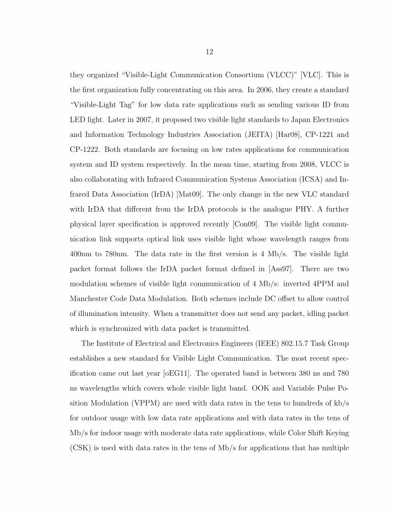
Japan is very active in putting visible light into communication purpose. In 2003,
12
they organized “Visible-Light Communication Consortium (VLCC)” [VLC]. This is
the first organization fully concentrating on this area. In 2006, they create a standard
“Visible-Light Tag” for low data rate applications such as sending various ID from
LED light. Later in 2007, it proposed two visible light standards to Japan Electronics
and Information Technology Industries Association (JEITA) [Har08], CP-1221 and
CP-1222. Both standards are focusing on low rates applications for communication
system and ID system respectively. In the mean time, starting from 2008, VLCC is
also collaborating with Infrared Communication Systems Association (ICSA) and In-
frared Data Association (IrDA) [Mat09]. The only change in the new VLC standard
with IrDA that different from the IrDA protocols is the analogue PHY. A further
physical layer specification is approved recently [Con09]. The visible light commu-
nication link supports optical link uses visible light whose wavelength ranges from
400nm to 780nm. The data rate in the first version is 4 Mb/s. The visible light
packet format follows the IrDA packet format defined in [Ass97]. There are two
modulation schemes of visible light communication of 4 Mb/s: inverted 4PPM and
Manchester Code Data Modulation. Both schemes include DC offset to allow control
of illumination intensity. When a transmitter does not send any packet, idling packet
which is synchronized with data packet is transmitted.
The Institute of Electrical and Electronics Engineers (IEEE) 802.15.7 Task Group
establishes a new standard for Visible Light Communication. The most recent spec-
ification came out last year [oEG11]. The operated band is between 380 ns and 780
ns wavelengths which covers whole visible light band. OOK and Variable Pulse Po-
sition Modulation (VPPM) are used with data rates in the tens to hundreds of kb/s
for outdoor usage with low data rate applications and with data rates in the tens of
Mb/s for indoor usage with moderate data rate applications, while Color Shift Keying
(CSK) is used with data rates in the tens of Mb/s for applications that has multiple

13
light sources and detectors. Furthermore, this standard shares the same MAC scheme
with IEEE 802.15.4 standard. In Chapter 4, we will discuss the potential problem
in this standard and compare it with Carrier Sense Multiple Access with Collision
Avoidance (CSMA/CA) and our proposed MAC scheme in terms of latency and rate.
Table 2.1: Summary of Current VLC StandardsTitle Distance Rates Region Applications
Visible Light Commu-nication System Stan-dard
unknown b/s-Mb/s Japan Low rate p2p
Visible Light ID Sys-tem Standard
unknown 4.8 kb/s Japan Low rates for IDs andtags
ICSA extension Several m 10 Mb/s Japan Indoor WLANIrDA extension >3 me-
ters576 kb/s-4Mb/s
Global High rate 1-to-N halfduplex
several m 300 b/s-9.6kb/s
Global Low rate 1-to-N dif-fuse link
VLC unknown 4 Mb/s Japan Extension of CP-1221,1222
IEEE 802.15.7 several m 10’s kb/s-10’s Mb/s
Global Indoor cases
IR
We briefly go through the regulations and standards of IR. The most important is-
sue of wireless optical communication is eye safety: it can pass through the human
cornea and be focused by the lens onto the retina, where it can potentially induce
thermal damage. Since human eyes can have the awareness of the existence of visible
light, there are additional power regulations on IR which VLC doesn’t have, such as
International Electrotechnical Commission (IEC) (IEC60825-1) [Com93] and Ameri-
can National Standards Institute (ANSI) (ANSI Z136.1) [Ins93]. They constrain the
power budget of optical device under certain levels. We will not go to the details
of them. One fact needed to mention is LED is large area emitter, and thus can be

14
operated at relatively higher power when comparing to laser device, and therefore
make it a better choice for indoor applications.
The most common standard about the wireless optical system is established by
IrDA in 1993 to create and promote inter-operable low cost IR data interconnection.
Its Serial Infrared Physical Layer defines standards for half-duplex point-to-point links
at several bit rates up to 4 Mb/s with 4-PPM, while 1.152 Mb/s links utilize OOK
with Return-to-Zero (RZ) pulses having a duty cycle of 0.25. Most IrDA receivers
adopt diffuse link, so that most IrDA links are of the hybrid-LOS type, which means
the transmitter and receiver are employed with different degree of directionality while
they still maintain LOS during transmission as shown in Figure 2·1. The transmitter
must have a peak-power wavelength between 850 nm and 900 nm. The normal range
is 1 m, however, in many cases, the range of links can extended as long as 3 m.
Later, Advanced Infrared (AIr) was developed to improve the performance such as
throughput. The speed for point-to-point link has been accelerated to 16 Mb/s and
it starts to support diffuse link with a data rate up to 4 Mb/s with repetition coding
[Ass97].
Another standard which defines optical signal communication is the well-known
IEEE 802.11 standard for IR. It defines two data rates, 1 Mb/s and 2 Mb/s, and uses
16-PPM and 4-PPM (Figure 2·5) respectively which results in the same chip rate,
4 M chips per second. It also uses the IR signal between 850 nm and 950 nm, and
achieves the communication range up to 10 m.
2.1.2 Link Topologies
The performance of the wireless optical communication can vary significantly depend-
ing on the topology of the link model used. [KB97] demonstrates the classification of
simple link models as shown in Figure 2·1. The first criterion is the degree of direction-
15
ality of the transmitter and receiver. Directed links employ directional transmitters
and receivers, which must be aimed in order to establish a link, while non-directed
links employ wide FOV transmitters and receivers. Directed link design maximizes
power efficiency, since it minimizes signal attenuation and reception of ambient light
noise. On the other hand, non-directed links may be more convenient to use, par-
ticularly for mobile devices, since they do not require aiming of the transmitter or
receiver.
Another classification criterion relates to whether the link relies upon the existence
of an uninterrupted LOS path between the transmitter and receiver. LOS links rely
upon such a path, while non-LOS links generally rely upon reflection of the light
from the ceiling or some other diffusely reflecting surface. LOS link design maximizes
power efficiency and minimizes multipath distortion. Non-LOS link design increases
link robustness, allowing the link to operate even when barriers stand between the
transmitter and receiver.
We will only discuss three wireless optical communication link models and compare
the channel characteristics of them. Detailed information can be found from many
papers, including [KB97] and [Hra04].
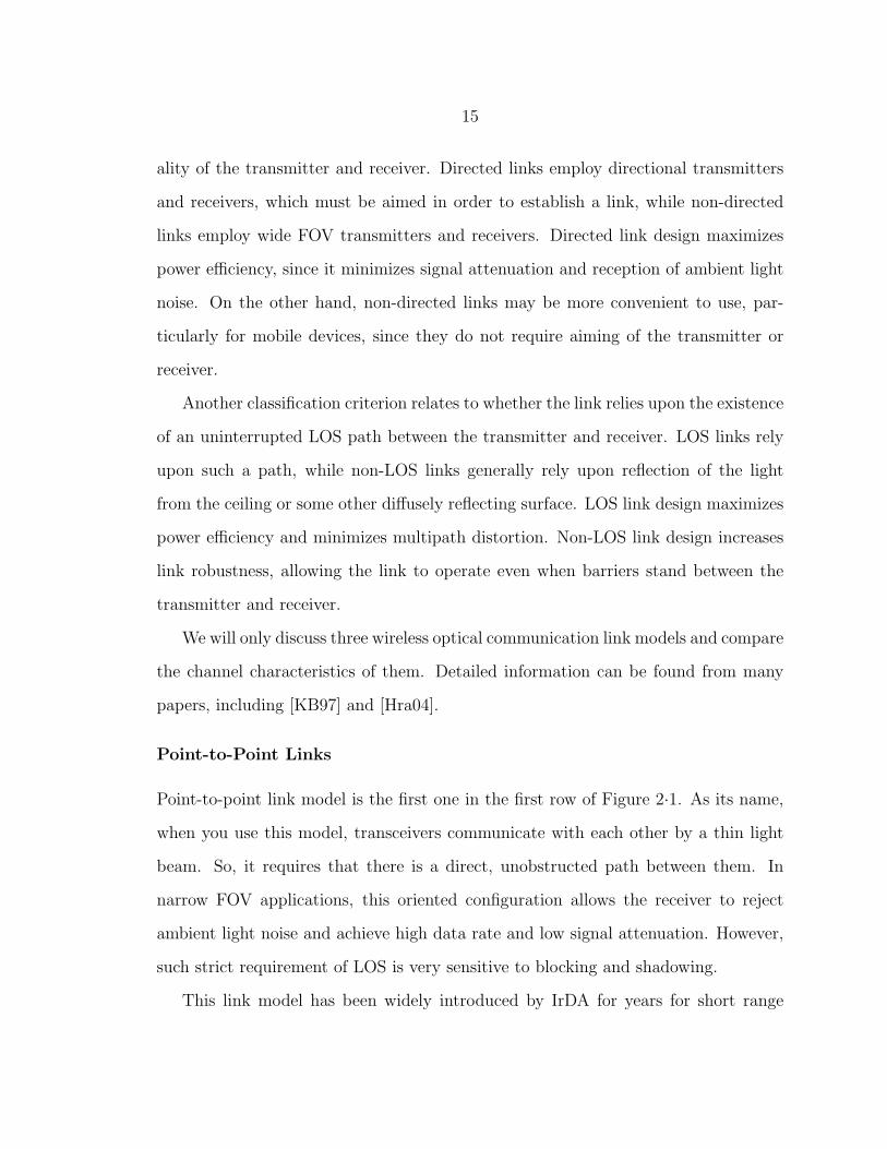
Point-to-Point Links
Point-to-point link model is the first one in the first row of Figure 2·1. As its name,
when you use this model, transceivers communicate with each other by a thin light
beam. So, it requires that there is a direct, unobstructed path between them. In
narrow FOV applications, this oriented configuration allows the receiver to reject
ambient light noise and achieve high data rate and low signal attenuation. However,
such strict requirement of LOS is very sensitive to blocking and shadowing.
This link model has been widely introduced by IrDA for years for short range

16
Figure 2·1: Classification of simple links according to the degree ofdirectionality of the transmitter and receiver and whether the link reliesupon the existence of a LOS path between them [KB97]
applications. For medium and long range transmission, 10 Mb/s and 100 Mb/s point-
to-point wireless infrared links to extend Ethernet networks have been developed over
a range of at most 10 m in an office environment by JVC [JVC] and Plaintree Systems
Inc. [Pla] respectively. Furthermore, the point-to-point link model can be extended to
the long range applications, such as Gb/s over 4 km [TNSP99], earth-to-space at rate
in excess of 1 Mb/s [WE00] and even for searching the extraterrestrial intelligence
[Pto].
Another solution of point-to-point links is space division multiplexing architecture
by which a transmitter outputs different data in different spatial directions to allow
for the simultaneous use of one wavelength by multiple users. Another means of
implementing a space division multiplexing system is to use a tracked optical wireless
architecture. In such system, the beams are steerable under the control of a tracking
17
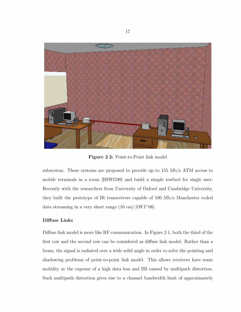
Figure 2·2: Point-to-Point link model
subsystem. These systems are proposed to provide up to 155 Mb/s ATM access to
mobile terminals in a room [BSWG99] and build a simple testbed for single user.
Recently with the researchers from University of Oxford and Cambridge University,
they built the prototype of IR transceivers capable of 100 Mb/s Manchester coded
data streaming in a very short range (10 cm) [OFJ+06].
Diffuse Links
Diffuse link model is more like RF communication. In Figure 2·1, both the third of the
first row and the second row can be considered as diffuse link model. Rather than a
beam, the signal is radiated over a wide solid angle in order to solve the pointing and
shadowing problems of point-to-point link model. This allows receivers have some
mobility at the expense of a high data loss and ISI caused by multipath distortion.
Such multipath distortion gives rise to a channel bandwidth limit of approximately

18
10-200 MHz [KKC95] [CK97]. Example IR devices are introduced in [Dif], [Smi98]
and [OFJ+06].
Figure 2·3: Diffuse link model
However, the diffuse link is free of multipath fading. This is because the short
carrier wavelength and large-area, square-law detector lead to efficient spatial diversity
that prevents multipath fading, and hence no change in the channel response is noted
if the photon detector is moved a distance on the order of a wavelength [KB97] and
[KKC95].
Experimental results have demonstrated a 50 Mb/s diffuse IR communication
link within 3 m for indoor applications [MK96]. In the commercial market, products
have been provided for many applications such as set-top box with claimed data
rate up to 5 Mb/s [Dif]. Another famous early application of diffuse link wireless
optical communication is the Active Badge System developed by Olivetti Research

19
Labs from 1989. People wear personal identification cards which emit infrared signal
to the receivers with a unique code in current room. With such signals, system can
collect the location information of each individual for certain purposes [Smi98].
Quasi-Diffuse Links
Figure 2·4: Quasi-Diffuse link model
Quasi-diffuse link model is a combination of point-to-point link model and diffuse
link model. The first and second one of the second row in Figure 2·1 can be considered
as Quasi-diffuse link model. In this model, the transmitter illuminates the ceiling
with multiple signal beams which form a grid of spot on the ceiling. In practical,
such narrow beams can be created either by individual light sources or holographic
beam splitters. On the other hand, the receiver either has multiple photon detectors
with non-overlapping FOV or one large FOV to cover a great potion of the ceiling.
This link model is also considered as a MIMO configuration which is named MSD

20
[AKJ04], [AK03] and [JHK04]. We discuss more in the Section 2.1.5.
Comparison
Characteristics Point-to-point Diffuse Quasi-diffuseRange(up to) Long Moderate Moderate
Rate High Low ModerateLOS Yes No No
Mobility No Yes YesImplementation Cost Low Moderate High
Table 2.2: Comparison among three link models
We have presented three major link models of wireless optical communication.
The point-to-point link model is a low complexity means to achieve high data rate at
the expense of mobility and pointing requirements. Diffuse link model suffers from
high signal attenuation and multipath distortion but can offers a great degree of
mobility and robustness to blocking. Quasi-diffuse link model has advantages from
both of two previous models but has a higher implementation cost. By summarizing
the discussion and publications mentioned, we have a general comparison among the
three basic link models in Table 2.2. Therefore, we can see that due to its many
unique characteristics, wireless optical communication is very application oriented
depending on required data rates and channel conditions.
Furthermore, as described later in Section 2.1.5, Quasi-diffuse link model may not
be a good choice since the light source is from the ceiling which also acts a lamp
for illumination. The main question is how to overcome the signal attenuation and
background noise for the diffuse link. This is essential for achieving high rate. One
possible solution is discussed in the Section 3.3. Also, another difference we are
trying to make is to build a device more universal for different services which may
have different critical requirements. The discussions of these two parts are included
later in this dissertation.

21
2.1.3 Modulation Schemes
The modulation of FSO is different from the RF. Currently the most viable modula-
tion is Intensity Modulation (IM), in which the desired waveform is modulated onto
the instantaneous power of the carrier. Correspondingly, the most practical method at
receive side is Direct Detection (DD), in which a photon detector produces a current
proportional to the received instantaneous power.
There are several different signal modulation schemes. In this section, we only
introduce some simple and popular schemes from [Hra04], particularly on their basic
types for the purpose of brevity. Currently, most popular schemes in used in this area
are binary-level for the reasons of simple and inexpensive implementations. Other
complex schemes can provide higher bandwidth efficiency with the tradeoff on power
efficiency and robustness.
Bit Rate Bandwidth Efficiency BEROOK 1
Tbit/s 1bit/s/Hz Q( P√
Rσ2)
PPM log2 MT
bit/s 1M
log2Mbit/s/Hz M2Q(P
√M log2 M
2Rσ2 )
PAM log2 MT
bit/s log2Mbit/s/Hz 2(M−1)M log2 M
Q( PM−1
√log2 MRσ2 )
QAM log2 M2
Tbit/s log2Mbit/s/Hz 2(M−1)
M log2 MQ( P
M−1
√log2 M2Rσ2 )
Table 2.3: Characteristics of different modulation schemes [Hra04]
On-Off Keying
OOK is a very popular scheme not only in wireless optical communication, but also
in other data communication. It is also called Non-Return-Zero (NRZ) encoding
scheme. In each symbol interval one of two symbols consisted of constant intensities
of zero or 2P is transmitted. The constellation for OOK consists of two points in a
one dimensional space. It is the simplest modulation scheme of FSO.

22
t
(a)
T
0
0
φOOK
(b)
2P√
T
(1)
tT 0
0
φ 2(t)
tT
4/√
T
tT 0
0
φ 4(t)
tT
4/√
T
(2)
t
(a)
T
0
0
φPAM
(b)
∆ 2∆ (M − 1)∆· · ·
(3)
t
(a)
t
(a)
0
0
(b)
φI
φ Q
(4)
Figure 2·5: Basis function (a) and Constellation of Symbols (b) for(1)OOK, (2)4-PPM, (3)PAM and (4)QAM
Pulse-Position Modulation
PPM is a standard modulation scheme used in wireless optical communication which
has been widely adapted previously in IR [Ass97]. It uses two distinct intensity levels
and each symbol interval is divided into M chips with same width. Information is
sent by putting only one of the chips non-zero. In this scheme, the signal space of
M -PPM is an M dimensional space with a single constellation point on each of the
M axes.
Pulse Amplitude Modulation
Pulse Amplitude Modulation (PAM) is a generalization of OOK from a set of two
symbols to a set of M symbols. It is a very basic scheme in RF communication. The
basis function is the same with OOK. The only difference is now we have a set of
23
non-negative scale factors instead of two. As a result, OOK is actually a special case
of rectangular PAM. PAM has all the constellation points in the same dimension.
Quadrature Amplitude Modulation
Quadrature amplitude modulation (QAM) is very popular in many communication
systems for achieving high speed data rate. Generally, the M2 symbols of M2-QAM
consist of an in-phase and quadrature component basis functions which are orthogonal
to each other due to the property of sinusoids. In addition, because the optical signal
has to be non-negative, a DC bias offset needed to be added to meet such requirement.
So, this scheme is bandwidth efficient with the expense of energy inefficiency [Hra04].
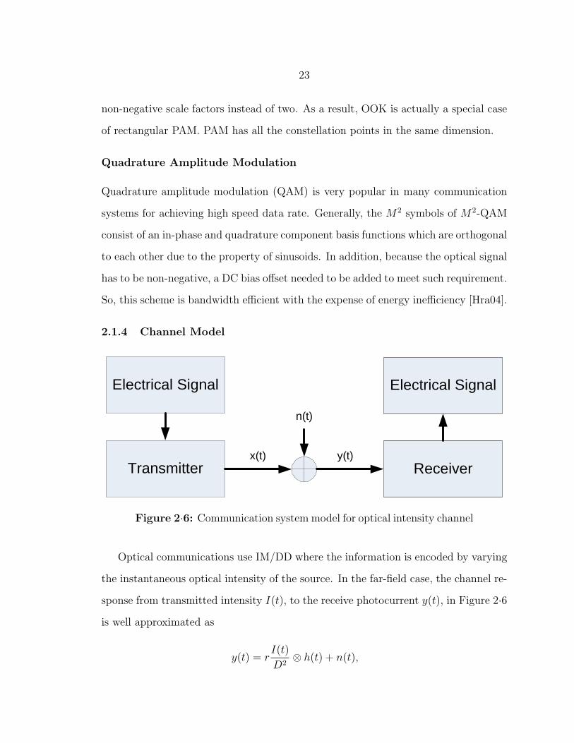
2.1.4 Channel Model
Transmitter
Electrical Signal
Receiver
Electrical Signal
x(t) y(t)
n(t)
Figure 2·6: Communication system model for optical intensity channel
Optical communications use IM/DD where the information is encoded by varying
the instantaneous optical intensity of the source. In the far-field case, the channel re-
sponse from transmitted intensity I(t), to the receive photocurrent y(t), in Figure 2·6
is well approximated as
y(t) = rI(t)
D2⊗ h(t) + n(t),
24
where r is the detector sensitivity, D is the distance between transmitter and receiver,
n(t) is the noise process and h(t) is the channel response [KB97, KKC95, CK97].
Because LEDs above threshold perform a near linear conversion between the input
drive current and the output optical intensity [KB97] [KKC95], the electro-optical
conversion can be modeled as I(t) = gx(t) where g is the optical gain of the device.
Without loss of generality, we set rg = 1 and let the 1/D2 be lumped into h(t), then
we have
y(t) = x(t)⊗ h(t) + n(t).
Different from RF, optical signal suffers from great signal attenuation after re-
flection (Non-LOS) [KB97]. Therefore, multipath effect is smaller for FSO system.
Furthermore, because multipath time spreading of the light is small compared to the
symbol interval (Ts) of the signal, it is reasonable to neglect ISI. This assumption is
valid for two types of systems: 1. links using focused light where there can be no
significant multipath components and 2. systems with bandwidth constraints below
10-100 MHz which have long symbol intervals.
Even though, channel response, h(t), is still a complex case-by-case problem which
is closely related to several parameters, such as location, size and the orientation of
the receiver and transmitter. Normally, for a wireless channel, there are three steps for
impulse response: measurement, simulation, and modeling. Channel measurements
have been described in several studies [KKC95, HYK+94]. These give us some fun-
damental understanding about the properties of certain environments of the channel
by generating a collection of hundreds of or thousands of example impulse responses.
Also, these researchers continue with the measurements based on a site-specific char-
acterization of the propagation environment [BKK+93, AH95]. For the last step of
characterizing the impulse response, [CK97] has extracted a simple model based on

25
previous steps of work which only use two parameters (signal attenuation and delay
spread) to characterize most general diffuse IR channels.
For most FSO systems where ambient light is strong to make the shot noise, which
will be discussed later, Gaussian, channel characteristic normally acts like lowpass
[Hra04], which means under certain bandwidth the relation between y(t) and x(t) is
linear. So, in most of researches, the channel is just considered as a baseband and it
is also one reason that the practical bandwidth is limited. Therefore, we can consider
the impulse response h(t) = H0δ(t).
Another particular constraint is the optical power due to eye and skin safety
requirements as described in Section 2.1.1. Different from RF where the constraint
is on the degree of square of the intensity, the constraint for FSO is on the degree of
non-negative amplitude itself.
The discussion of n(t) is more complex. As is the case in RF communication, the
determination of noise sources as the input of the receiver is critical since this is the
location where the incoming signal contains the least power. Generally, there are two
major types of noise.
Thermal Noise
Thermal noise, or circuit noise, is a random fluctuation in voltage caused by the
random motion of the receiving electronics [Ros]. A major source is the noise caused
by resistive elements in the pre-amplifier. Thermal noise is generated independently
of the received signal and can be modeled as having a Gaussian distribution and in
general, is non-white [KB97].
Shot Noise
Photon-generated shot noise is a major noise source in the wireless optical communi-
cation. It arises due to both the ambient light and transmitted signal. Many wireless

26
optical links operate in the scenarios where there is intense background illumination.
In these cases, the ambient light shot noise component dominates the shot noise, and
therefore is the dominant source of noise in a wireless optical channel [Hra04].
This random process arises fundamentally due to the discrete nature of energy
and charge in the photodiode, which normally can be modeled as having a Poisson
distribution with a white power spectral density [KOG70]. So, the high intensity
shot noise is the result of the summation of many independent, Poisson distributed
random variables. In the limit, the cumulative distribution approaches a Gaussian
distribution. Thus, for most of indoor wireless optical communication the noise source
is normally modeled as a white, signal independent Gaussian distribution [Hra04].
Narrow FOV links are able to reject a large component of ambient light. The
resulting noise can still be modeled as being Gaussian distributed but dependent on
the transmitted signal. In the case of wide FOV receivers, where the ambient light
dominates the received signal, it is modeled as additive, white, signal independent
Gaussian distribution with zero mean and variance σ2 (AWGN) [KB97, Car03, Hra04].
Furthermore, the Power Spectral Density (PSD) of shot noise is
Sshot(f) = 2qRPn,
where q is the electronic charge, R is the responsivity and Pn is the average power of
ambient light. Therefore, the SNR will be
SNR =R2P 2
σ2shot
=R2P 2
2qRPnIRb
,
where P is the average power of desired signal, I is noise-bandwidth factor and Rb
is the data rate [KB97]. Besides these parameters, SNR is also related to spectral
irradiance, ambient light angle, peak transmission and noise bandwidth of the optical
filter, detector physical area and refractive index of the concentrator. So, the numer-

27
ical result SNR can be varied in a wide range. A typical value is within 10 to 20 dB
depending on the link model.
For a more direct understanding about the noises in wireless optical communi-
cation, an example is given from [KB97]. The power spectral densities of different
noises can be plotted in Figure 2·7, assuming parameters that might be typical of a
receiver operating in a 10 Mb/s diffuse link.
(a) (b)
Figure 2·7: (a) Dominant input-referred noise power spectral densities(b) Dominant input-referred noise variances [KB97]
2.1.5 Multi-Input Multi-Output
MIMO system is the use of multiple antennas at both the transmitter and receiver
to improve communication performance. Those multiple antennas used in either
transmitters or receivers will create more signal passage channels under the condition
that they will be able to be separated at the receiver without mutual interference.
Only in this way, the signals flows independence among different TxCRx channels can
be exploited to achieve certain kinds of gains in “spatial diversity” or “multiplexing”,
depending on the applications.

28
In FSO, there are several research conducted on this topic. In [WBPCL05], [TO04]
[NUL04] and [SHJ05], authors give us some fundamental research on the general study
of MIMO system in wireless optical channels. In the mean time, two unique types of
MIMO system are studied due to unique characteristics of the practical configurations.
(a) (b)
Figure 2·8: (a) Pixelated system [HK06] (b) MSD system [AKJ04]
In [Hra04] and [HK06], authors introduce a pixelated wireless optical system,
which transmits data at high rates using a series of coded time-varying images in a
short range (2m). The pixelated wireless optical channel is ideally suited to applica-
tions that require high speed short range communication in which a LOS is available.
However, the requirement of LOS limits its applications. The communication distance
is too short to make it a good solution for more general indoor cases. Furthermore,
physical movement like rotation can greatly affect performance. Mainly, it is only
considered for some personal device usages.
Another type of MIMO system, MSD, is introduced by Kavehrad [AKJ04], [AK03]
and [JHK04]. It has been mentioned as Quasi-Diffuse links in previous section. The
desktop level transmitter sends out multiple identical narrow beams, which have
small signal attenuation, to illuminate small size areas on the ceiling, called diffusing
spots. Then after reflecting, each spot can be considered as a lighting source with
a Lambertian illumination pattern. An angle diversity receiver which has multiple

29
narrow non-overlapping FOV receiving elements is used to provide diversity gain.
Recently, there are new FSO systems adopting MIMO in the traditional way to
demonstrate higher transmission rate or avoid interference. They are introduced in
Section 2.2.
2.1.6 Direct Sequence Spread Spectrum
Direct Sequence Spread Spectrum (DSSS), also refers to Direct Sequence Code Divi-
sion Multiple Access (DS-CDMA), is a much more complex scheme which handles the
channel access from the aspect of signaling. DSSS is one in which the transmitted sig-
nal is spread over a wide frequency band, much wider than the minimum bandwidth
required to transmit the information being sent. Band spreading is accomplished by
means of a Pseudo-Noise (PN) code, quasi-orthogonal or orthogonal codes, which is
independent of the data. When the PN codes have a good orthogonal property, mod-
ulated signal can be recovered with a simple Rake receiver. The initial purpose of
DSSS is military anti-jamming tactical communications for its property of noise-like
signal to each other. However, after that, researchers explore its usage in wireless
communication mainly for its property of simultaneously sharing of the transmission
medium.
Figure 2·9: Direct Sequence Spread Spectrum [FK03]

30
The choice of code sequences is important. Different from coherent CDMA that
using bipolar codes, in optical communication, the signal is non-negative that only
unipolar codes can work. One good candidate is Optical Orthogonal Codes (OOC)
[CSW89]. It can provide asynchronous multiple access communications with easy
synchronization and good performance in CDMA communication networks.
Although there is no need to synchronize data between different transmitters,
synchronization between transceivers is still needed. It consists of two stages, namely,
acquisition and tracking. They function similarly but are responsible for OOC and
data respectively. A simple serial-search method is demonstrated in [KS01].
However, the benefit comes with a great expensive on Multi Access Interference
(MAI), lower Signal-to-Interference-plus-Noise Ratio (SINR) per degree of freedom
of the individual links. The more users accepted in the system, the more severe
of the problem. Furthermore, the near-far problem occurs when the power of the
signal received from one transmitter is so strong that the signal received from other
transmitter is completely jammed.
2.2 Related Works
In this section, we demonstrate some VLC prototypes designed by the researchers.
Some of them are for outdoor purposes, and some for indoor applications. Some
can support high speed rate requirement like High-Definition (HD) video streaming,
and Some are suitable for low rate systems like in-building tracking. By having an
overview of these state-of-the-art achievements, we can have a more direct idea about
where the VLC system can be used.
31
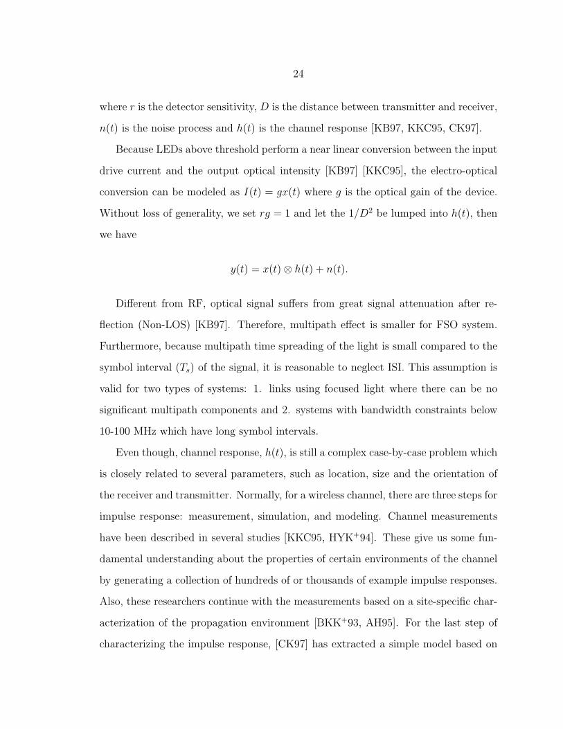
2.2.1 Prototypes
We first start with research groups which have demonstrated their prototype VLC
systems. Figure 2·10 shows most VLC prototypes introduced in recent years for
indoor applications with the range shorter than 10 m.
Figure 2·10: Short range (<10 m) VLC Prototypes with Visible LightMedium [GRLW08a] [VKN+09b] [VKN+09a] [VFK+10] [VKN+10b][VKN+10a] [MOF+09] [MOF+08b] [ATO10] [BPW+10] [ASWH09][YCZ+09]
The size of the dot represents the luminous emittance of the transmitter of each

32
prototype. It is closely related to FOV, optical power and range.
Mv =F
S
=F
π(R ∗ tan( θ2))2
,
where Mv is luminous emittance, F is Luminous flux, S is footprint of coverage, R is
range and θ is full FOV angle at half power of LED.
So, it is a good metric to compare among different VLC systems. As indicated
in the Figure 2·10, currently, most of indoor prototypes focus on high rate without
consideration of range. However, a practical system should be able to support appli-
cations with longer range. Therefore, up-right corner with large dot which indicates
long range, high rate and good illumination (high flux per m2) is our target.
OMEGA Project
One of the most important projects involving VLC is OMEGA project, the Home
Gigabit Access project. For widespread acceptance, wireless networks are required,
and the OMEGA project aims to develop gigabit home networks “with no new wires”
[OME]. Such networks will use RF and optical wireless communications together
with (local) power line communications. Optical wireless links will provide high-
speed (Gb/s) LOS data transmission at wavelengths in the near-infrared range. In
addition, novel VLC will be used to broadcast data at bit rates of 100 Mb/s while
providing illumination within the home [OME].
Funded by European Union (EU) through OMEGA project, researchers from
Fraunhofer Institute of Telecommunications (FIT) have been collaborating with Siemens
Corporate Technology, France Telecom and other researchers on VLC. They started
with some background of OMEGA project and theoretical results demonstrated in
[LGB+08] [GRLW08b]. They considered a medium-sized model room which has ceil-

33
Figure 2·11: Schematic of OMEGA project [LGB+08]
ing lamp consisting of LEDs with 60 degree off-center angle and 20 MHz modulation
bandwidth. The vertical distance from the desktop receiver to the lamp is about
1.65 meters. The simulations show that by suppressing the phosphorescent portion
of the optical spectrum upon detection and adopting DMT with high order QAM,
the achievable rates lie in the region of several hundred Mb/s.
In the mean time, they started implementing the research work with several ex-
periments. In 2008, they demonstrated a simple single phosphor-based white-light
LED and p-i-n photodiode prototype [GRLW08a]. Within a very short distance (1
cm) to maintain an illuminance of 700 lx at the detector plane, the system is able to
carry out 40 Mb/s with OOK and 101 Mb/s with DMT. Later on, in 2009, they im-
proved the rate of the system with OOK into 125 Mb/s at a range of 5m while having
illumination levels at the receiver fit into the range recommended by the standard for

34
Figure 2·12: Prototypes from FIT [VFK+10] [BPW+10]
(office) general lighting [VKN+09b]. The same year, with both approaches of blue
filtering and DMT, they were able to achieve 200+ Mb/s under 1100 lx illumination
[VKN+09a]. However, the distance is still as short as 0.7 m. Last year, they con-
tinued with several other prototypes. In [VFK+10], they showed an implementation
of a real-time DMT-based visible-light link operating at 100 Mbit/s using a low-cost
commercially available white LED for video streaming. In [VKN+10a], they reported
the demonstration of a visible-light link with OOK operating at 230 Mb/s with use
of an Avalanche Photodiode (APD) and 125 Mb/s with use of a p-i-n photodiode,
both without equalization. In [BPW+10], they managed to stream three HD video
simultaneously by a single LED at a distance of 1.2 m with the rate of 20 Mb/s for
each. In [VKN+10b], they finally achieved 500+ Mb/s, the fastest rate ever published
until now, based on a commercial thin-film high-power phosphorescent white LED,
an APD, and off-line signal processing of DMT signals.
35
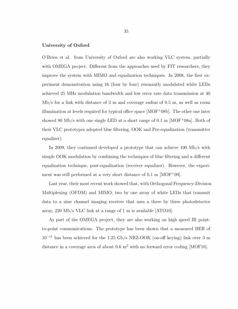
University of Oxford
O’Brien et al. from University of Oxford are also working VLC system, partially
with OMEGA project. Different from the approaches used by FIT researchers, they
improve the system with MIMO and equalization techniques. In 2008, the first ex-
periment demonstration using 16 (four by four) resonantly modulated white LEDs
achieved 25 MHz modulation bandwidth and low error rate data transmission at 40
Mb/s for a link with distance of 2 m and coverage radius of 0.5 m, as well as room
illumination at levels required for typical office space [MOF+08b]. The other one later
showed 80 Mb/s with one single LED at a short range of 0.1 m [MOF+08a]. Both of
their VLC prototypes adopted blue filtering, OOK and Pre-equalization (transmitter
equalizer).
In 2009, they continued developed a prototype that can achieve 100 Mb/s with
simple OOK modulation by combining the techniques of blue filtering and a different
equalization technique, post-equalization (receiver equalizer). However, the experi-
ment was still performed at a very short distance of 0.1 m [MOF+09].
Last year, their most recent work showed that, with Orthogonal Frequency-Division
Multiplexing (OFDM) and MIMO, two by one array of white LEDs that transmit
data to a nine channel imaging receiver that uses a three by three photodetector
array, 220 Mb/s VLC link at a range of 1 m is available [ATO10].
As part of the OMEGA project, they are also working on high speed IR point-
to-point communications. The prototype has been shown that a measured BER of
10−11 has been achieved for the 1.25 Gb/s NRZ-OOK (on-off keying) link over 3 m
distance in a coverage area of about 0.6 m2 with no forward error coding [MOF10].

36
Figure 2·13: Prototypes from University of Oxford [ATO10] [MOF10]
Nagoya University
Japan is another region that is very active on VLC. Because of the close collaboration
with camera companies like Canon and Nikon, their researches address very differ-
ently. First, instead of photodiode, with the advantage of camera company partners,
they use image sensor for most of the time. Second, they put more effort on outdoor
long distance scenarios and applications, such as vehicle networks and traffic control.
The first experiment was carried out in 2005. The experimental rate is only 2.78
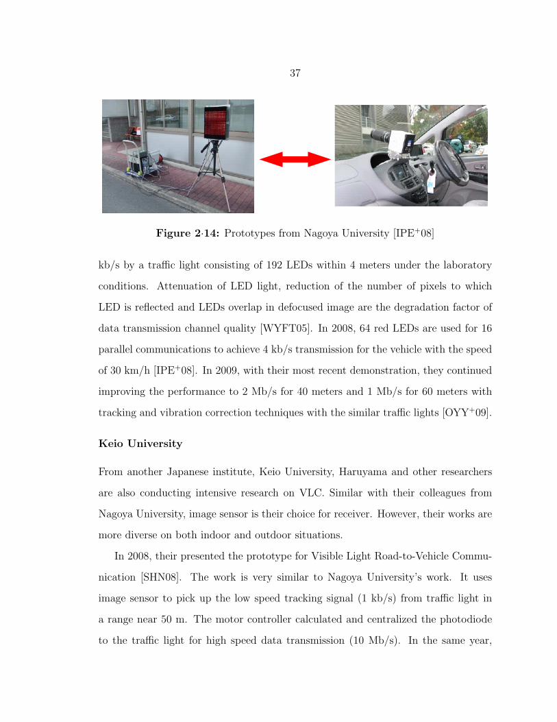
37
Figure 2·14: Prototypes from Nagoya University [IPE+08]
kb/s by a traffic light consisting of 192 LEDs within 4 meters under the laboratory
conditions. Attenuation of LED light, reduction of the number of pixels to which
LED is reflected and LEDs overlap in defocused image are the degradation factor of
data transmission channel quality [WYFT05]. In 2008, 64 red LEDs are used for 16
parallel communications to achieve 4 kb/s transmission for the vehicle with the speed
of 30 km/h [IPE+08]. In 2009, with their most recent demonstration, they continued
improving the performance to 2 Mb/s for 40 meters and 1 Mb/s for 60 meters with
tracking and vibration correction techniques with the similar traffic lights [OYY+09].
Keio University
From another Japanese institute, Keio University, Haruyama and other researchers
are also conducting intensive research on VLC. Similar with their colleagues from
Nagoya University, image sensor is their choice for receiver. However, their works are
more diverse on both indoor and outdoor situations.
In 2008, their presented the prototype for Visible Light Road-to-Vehicle Commu-
nication [SHN08]. The work is very similar to Nagoya University’s work. It uses
image sensor to pick up the low speed tracking signal (1 kb/s) from traffic light in
a range near 50 m. The motor controller calculated and centralized the photodiode
to the traffic light for high speed data transmission (10 Mb/s). In the same year,
38
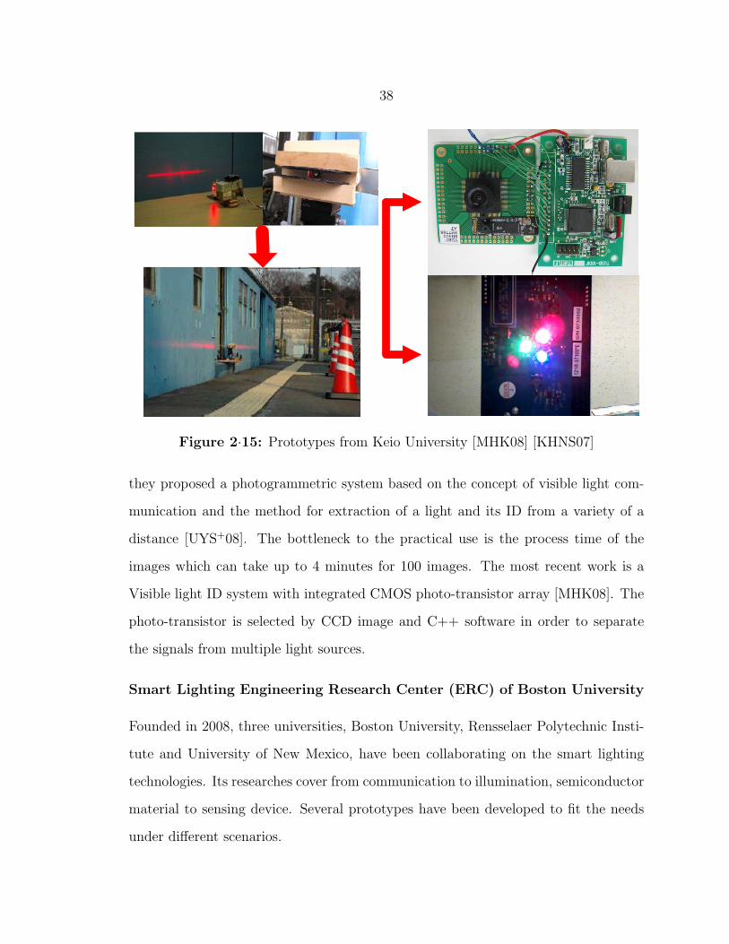
Figure 2·15: Prototypes from Keio University [MHK08] [KHNS07]
they proposed a photogrammetric system based on the concept of visible light com-
munication and the method for extraction of a light and its ID from a variety of a
distance [UYS+08]. The bottleneck to the practical use is the process time of the
images which can take up to 4 minutes for 100 images. The most recent work is a
Visible light ID system with integrated CMOS photo-transistor array [MHK08]. The
photo-transistor is selected by CCD image and C++ software in order to separate
the signals from multiple light sources.
Smart Lighting Engineering Research Center (ERC) of Boston University
Founded in 2008, three universities, Boston University, Rensselaer Polytechnic Insti-
tute and University of New Mexico, have been collaborating on the smart lighting
technologies. Its researches cover from communication to illumination, semiconductor
material to sensing device. Several prototypes have been developed to fit the needs
under different scenarios.

39
Figure 2·16: Prototypes from Boston University [LDS+08] [WCL11]
Little et al. at Boston University demonstrated a short range (3 m) duplex point-
to-point white-LED system with the rate of 56 kb/s [LDS+08] developed with readily-
available electronics and LEDs, demonstrating the viability, simplicity, and low cost
of VLC solutions rather than their upper bound in terms of achievable data rates.
The same team created a prototype that delivers in excess of 1 Mb/s while providing
both illumination and communication at several meters and has been demonstrated
as an array of seven luminaries in the form of overhead spot lighting [CML10]. Other
prototype works currently include Vehicle-to-Vehicle VLC and SDR Transceivers.

40
2.2.2 Other Research Groups
There are several other groups have been or are still active on the VLC region. Here,
we briefly introduce some of their works.
Niigata University
Different from other prototypes, fluorescent light communications is another possible
way for VLC. Recently, Liu et al. from Niigata University have developed a system
[LMKM08] and performed a series of experiments using 22 fluorescent lights and 3
different angular degree sensors for indoor guidance and location detection inside a
building. Although the maximum rate is only 9.6 kb/s within 2 m, it can support
walking speed and be used as reference for the research using next generation LED
lighting.
NTT Corporation
The prototype developed by Douseki is an indoor application for communication
within a range of 40 cm deployed as a desktop lamp that consists of 200 white LEDs
without batteries [Dou04]. Power is derived from a solar cell which also acts as a
photon detector for receiving data. This unique design can support transmission up
to 100 kb/s.
University of Hong Kong
Pang et al. constructed a system with visible LEDs for traffic light based communica-
tion in 1999 [PKLC02]. This is first LED based VLC system as we know. The group
set up a system with 441 red ultra-bright LEDs in the lab over 20 m. The system
can achieve a rate at 128 kb/s. The goals are providing audio and digital signals
transmission for outdoor applications such as roadside-to-vehicle communications.

41
Chinese Academy of Science
In mainland China, several universities have launched their projects on VLC. The
first presented prototype was designed by Chinese Academy of Science [YCZ+09].
With error check and correction abilities, the system can keep 10−7 error bit rate
within 2.5 m reach at a rate up to 115200 b/s. Their most recent works have been
pushing VLC for mobile phone and home automation. The primary targets are low
rate control and tracking applications.
Yonsei University
Yonsei University has developed a VLC system recently [ASWH09]. 49 LEDs are
placed to form a 7 by 7 array on the transmitter. 5 Mb/s half duplex visible light
wireless optical link based on optical access network over a distance of 40 cm was
claimed.
Asian Institute of Technology
Researchers from Asian Institute of Technology and Chulalongkorn University in
Thailand developed a low data rate VLC system [SSV+10]. 4 by 10 RGB LEDs are
used to support transmission rates of 19.2 kb/s to the receiver located directly below
the panel, and 4.8 kb/s to the receiver located on the table top 1.4 m horizontally
away from the center location.
Intel Labs
Richard Roberts introduced a novel way of using VLC for vehicle safety. An au-
tomobile positioning scheme that uses the existing automotive LED lighting to send
amplitude modulated ranging tones was presented [RGR10]. By calculating the phase
difference of arrival, the system is able to determine the distance difference between
transceivers.

42
University of California, Riverside
Dr. Zhengyuan Xu from University of California, Riverside also introduced their first
VLC system in 2010. The system can operate at a maximum horizontal separation of
3.5 m and vertical distance of 1 m with maximum data rate of 115 kb/s [CCXR10].
Entrepreneur Companies
Furthermore, VLC commercial products and services are becoming available from
several entrepreneur companies.
LVX System is a managing organization of 55 separate companies that work to-
gether to offer a revolutionary lighting technology that provides energy efficient light-
ing and visible light wireless communication services [LVX].
Talking Lights LLC was founded by Professor Steven Leeb and Dr. E.C. Lupton
of the Electrical Engineering and Computer Science Department of the Massachusetts
Institute of Technology. Its VLC system aims to achieve GPS-like position identifi-
cation and guidance indoors, where GPS cannot operate [TAL].
ByteLight provides revolutionary lighting technologies that transform overhead
lighting into a platform for sensing, communication and localization. With their
LightControl software, LightLocal transceivers and LightView software, facility man-
agers are able to reduce energy cost, pinpoint the location of any device and improve
operational efficiency by up to 25 percent [BYT].

43
Chapter 3
Modeling and Signaling of Indoor VLC
In this chapter, we present our research on signaling issues of indoor VLC. Two sec-
tions are included. In the first section, we start with modeling VLC system in a room
assumed to serve as an office, and the main purpose of the lighting is to illuminate a
desk located at the center of the room as illustrated in Figure 3·1. Although the re-
sults are derived based on set of parameters of our VLC prototype, the approach can
be adopted to any indoor VLC systems. The purpose is to provide a novel overview
for indoor VLC in terms of performances, such as signal attenuation, BER, SNR and
rate.
Furthermore, in the second section, a general discussion on DMT (baseband
OFDM) is also presented for the reason that it can achieve better bandwidth effi-
ciency. The analysis reveals directions about how we can improve the indoor VLC
system in terms of better throughput.
3.1 Framework for Indoor Scenarios
3.1.1 Room Geometry
Before the discussion of the performance analysis, we first introduce the geometry of
the office room and also the characteristics of LEDs. In order to make the results
of our investigation comparable to those used in the others’ studies, we consider a
general indoor scenario, an empty room with identical dimensions. We set the size
to a 12×12×3m3 cube. In this model, the receiver is assumed to be placed at 1
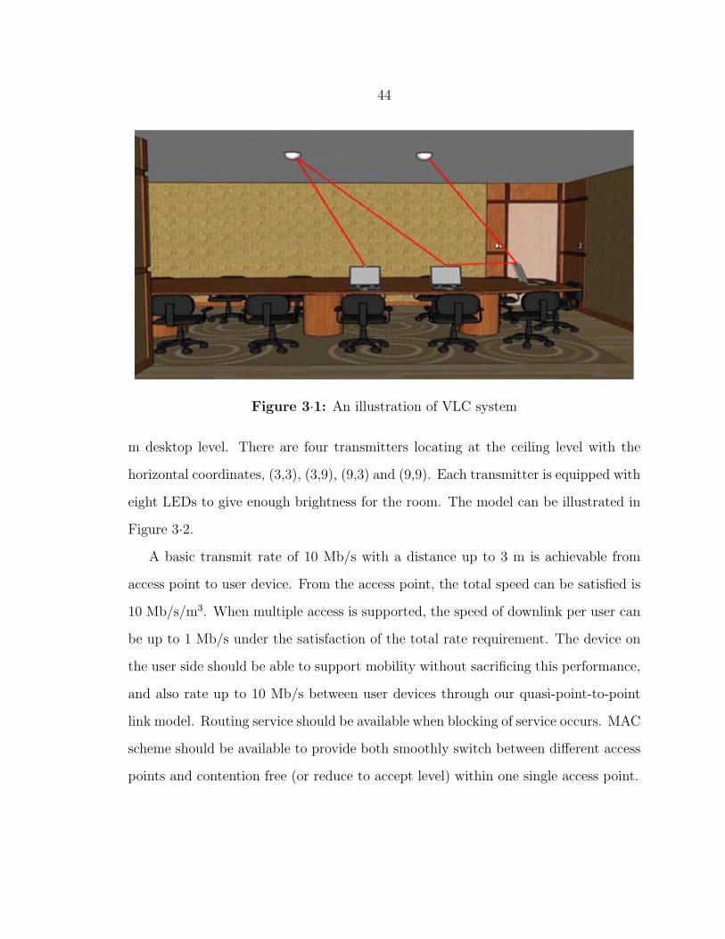
44
Figure 3·1: An illustration of VLC system
m desktop level. There are four transmitters locating at the ceiling level with the
horizontal coordinates, (3,3), (3,9), (9,3) and (9,9). Each transmitter is equipped with
eight LEDs to give enough brightness for the room. The model can be illustrated in
Figure 3·2.
A basic transmit rate of 10 Mb/s with a distance up to 3 m is achievable from
access point to user device. From the access point, the total speed can be satisfied is
10 Mb/s/m3. When multiple access is supported, the speed of downlink per user can
be up to 1 Mb/s under the satisfaction of the total rate requirement. The device on
the user side should be able to support mobility without sacrificing this performance,
and also rate up to 10 Mb/s between user devices through our quasi-point-to-point
link model. Routing service should be available when blocking of service occurs. MAC
scheme should be available to provide both smoothly switch between different access
points and contention free (or reduce to accept level) within one single access point.
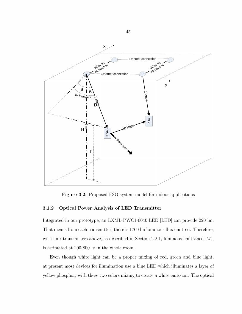
45
PD
A
3 m
1 Mbps
θ ß
H
D
h
x
y
PD
A
10 Mbps
10 Mbps/m 3
Walking speed
Ethernet connection
Ethernet
connection
Ethernet connection
Ethernet
connection
1 Mbps
Figure 3·2: Proposed FSO system model for indoor applications
3.1.2 Optical Power Analysis of LED Transmitter
Integrated in our prototype, an LXML-PWC1-0040 LED [LED] can provide 220 lm.
That means from each transmitter, there is 1760 lm luminous flux emitted. Therefore,
with four transmitters above, as described in Section 2.2.1, luminous emittance, Mv,
is estimated at 200-800 lx in the whole room.
Even though white light can be a proper mixing of red, green and blue light,
at present most devices for illumination use a blue LED which illuminates a layer of
yellow phosphor, with these two colors mixing to create a white emission. The optical

46
power Pt of such LED is normally obtained from radiation spectrum St(λ) by
Pt =
λH∫λL
St(λ)dλ.
However, typically most of manufacturers only give the normalized radiation spec-
trum S ′t(λ) as displayed in Figure 3·3. If we denote a scaling factor ct = St(λ)/S
′t(λ),
it can be found from [Sch06]
ct =Ft
683∫ 780nm
380nmS ′t(λ)V (λ)dλ
,
where Ft is total luminous flux and V (λ), the eye sensitivity function, can be approx-
imated by the following Gaussian curve fitting [PG09]
V (λ) ∼= 1.019e−285.4(λ−0.559)2 .
Figure 3·3: Radiation spectrum of LXML-PWC1-0040 [LED]
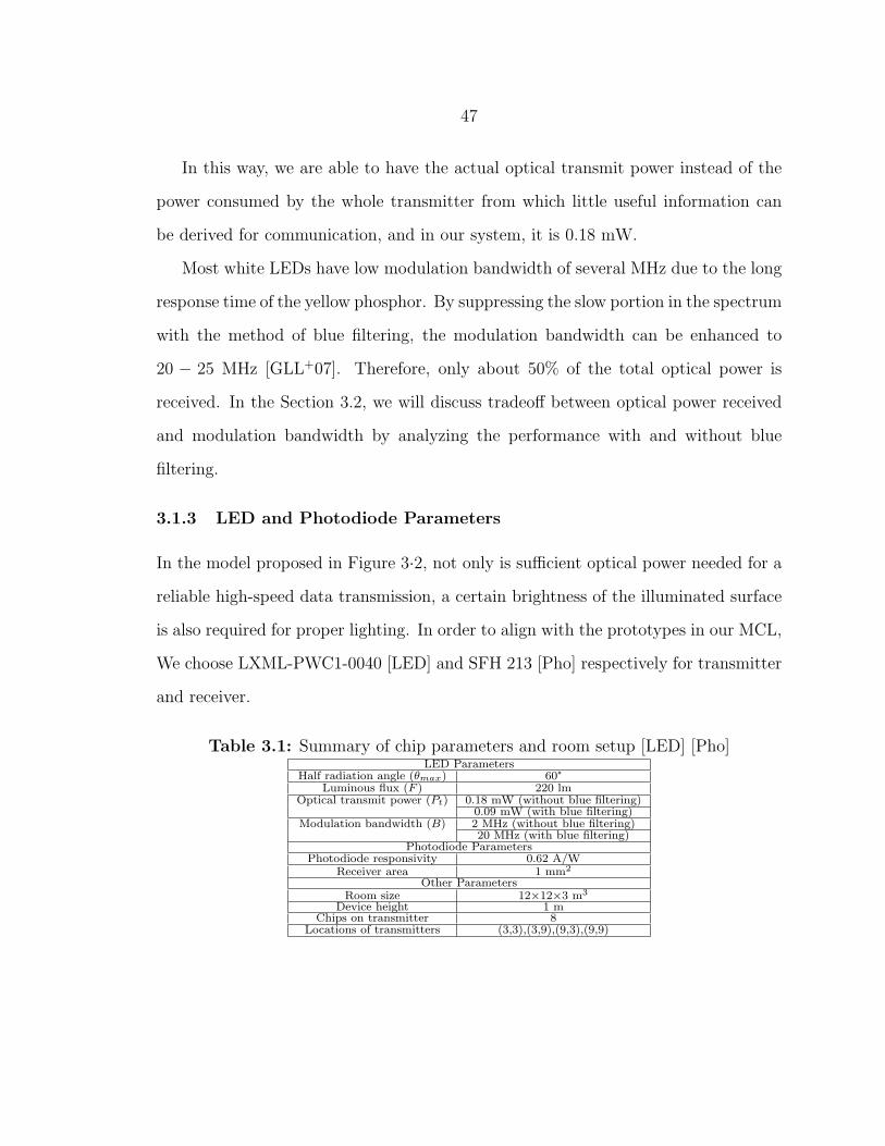
47
In this way, we are able to have the actual optical transmit power instead of the
power consumed by the whole transmitter from which little useful information can
be derived for communication, and in our system, it is 0.18 mW.
Most white LEDs have low modulation bandwidth of several MHz due to the long
response time of the yellow phosphor. By suppressing the slow portion in the spectrum
with the method of blue filtering, the modulation bandwidth can be enhanced to
20 − 25 MHz [GLL+07]. Therefore, only about 50% of the total optical power is
received. In the Section 3.2, we will discuss tradeoff between optical power received
and modulation bandwidth by analyzing the performance with and without blue
filtering.
3.1.3 LED and Photodiode Parameters
In the model proposed in Figure 3·2, not only is sufficient optical power needed for a
reliable high-speed data transmission, a certain brightness of the illuminated surface
is also required for proper lighting. In order to align with the prototypes in our MCL,
We choose LXML-PWC1-0040 [LED] and SFH 213 [Pho] respectively for transmitter
and receiver.
Table 3.1: Summary of chip parameters and room setup [LED] [Pho]LED Parameters
Half radiation angle (θmax) 60°Luminous flux (F ) 220 lm
Optical transmit power (Pt) 0.18 mW (without blue filtering)0.09 mW (with blue filtering)
Modulation bandwidth (B) 2 MHz (without blue filtering)20 MHz (with blue filtering)
Photodiode ParametersPhotodiode responsivity 0.62 A/W
Receiver area 1 mm2
Other ParametersRoom size 12×12×3 m3
Device height 1 mChips on transmitter 8
Locations of transmitters (3,3),(3,9),(9,3),(9,9)

48
3.2 Channel Signal Attenuation Model
In this section, a general LOS channel model is considered. Evaluation of signal
attenuation and other three characteristics are derived based on the photometric
parameters we introduce in the Section 3.1.3. The results we obtain here can provide
certain insight and guidance for indoor VLC systems.
3.2.1 Signal Attenuation
The channel model we adopt is from [RX09]. It only considers LOS links. The diffuse
link model is shown as Figure 3·4. Based on it, we evaluate the corresponding signal
attenuation that is used for the other communication performance study later. The
notations are defined in Table 3.2.
Transmitter
Transmitter
Figure 3·4: LOS diffuse link model for signal attenuation [RX09]

49
Table 3.2: Parameter definition for LOS diffuse link modelParameter Definition
D Distance from receiver to sourcer Receiver aperture radiusα Angle from source-receiver line to receiver axisβ Angle from source-receiver line to source axisI0 Axial intensity with unit candela
gt(θ) Normalized spatial radiation pattern
We assume the transmitter LED has the spatial luminous intensity distribution
I0gt(θ), where I0 is the axial intensity with unit candela and gt(θ) is the normal-
ized spatial radiation pattern provided by [LED]. Therefore, the total transmitted
luminous flux of the transmitter LED is
Fs =
Ωmax∫0
I0gt(θ)dΩ
= I0
θmax∫0
2πgt(θ)sinθdθ,
where Ωmax is the LED beam solid angle, which is related to the LED half radiation
angle θmax as
Ωmax = 2π(1− cosθmax).
Therefore, [RX09], the signal attenuation performance can be calculated by
L =Fr
Fs
=I0gt(β)Ωr
I0∫ θmax
02πgt(θ)sinθdθ
≈ gt(β)Ar
D2∫ θmax
02πgt(θ)sinθdθ
,
in which Ar donates receiver area, gt() and θmax are given in [LED], and α is considered

50
as zero for simplicity, which means the receiver is always pointing vertically to the
ceiling.
Another note is that the received optical power is the summation of optical power
from all LED chips in the room, instead of one single LED in the formula.
3.2.2 SNR
In FSO, the noise can consist of several types of noise sources, such as fluorescent light
interference, thermal noise and photon-generated shot noise. Shot noise, stemming
from ambient light, is a major noise source in the wireless optical communications.
From [KB97], conservatively, the noise power spectral density is
N0∼= Nshot = 2qγPn ∼ 10−22A2/Hz,
where q is the electronic charge, γ is the responsivity and Pn is the average power of
ambient light.
Therefore, for certain bit rate of Rb we can have the receiver electrical SNR defined
in [KB97] for any spot in the room,
SNR =γ2P 2
r
RbN0
.
3.2.3 Upper Bound of the Rate
Another important measure of performance is throughput. Although the actual
achievable rate depends on several parameters, the rate upper bound from Shannon
theorem can still give certain evaluation of performance.
Considering all possible multi-level and multi-phase encoding techniques, the
Shannon theorem states that the channel capacity C, meaning the theoretical tightest
upper bound on the information rate (excluding error correcting codes) that can be
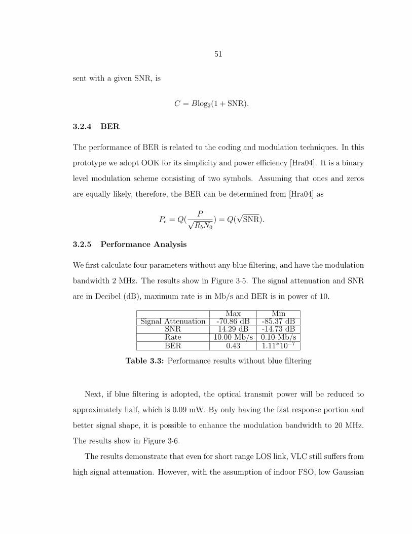
51
sent with a given SNR, is
C = Blog2(1 + SNR).
3.2.4 BER
The performance of BER is related to the coding and modulation techniques. In this
prototype we adopt OOK for its simplicity and power efficiency [Hra04]. It is a binary
level modulation scheme consisting of two symbols. Assuming that ones and zeros
are equally likely, therefore, the BER can be determined from [Hra04] as
Pe = Q(P√RbN0
) = Q(√SNR).
3.2.5 Performance Analysis
We first calculate four parameters without any blue filtering, and have the modulation
bandwidth 2 MHz. The results show in Figure 3·5. The signal attenuation and SNR
are in Decibel (dB), maximum rate is in Mb/s and BER is in power of 10.
Max MinSignal Attenuation -70.86 dB -85.37 dB
SNR 14.29 dB -14.73 dBRate 10.00 Mb/s 0.10 Mb/sBER 0.43 1.11*10−7
Table 3.3: Performance results without blue filtering
Next, if blue filtering is adopted, the optical transmit power will be reduced to
approximately half, which is 0.09 mW. By only having the fast response portion and
better signal shape, it is possible to enhance the modulation bandwidth to 20 MHz.
The results show in Figure 3·6.
The results demonstrate that even for short range LOS link, VLC still suffers from
high signal attenuation. However, with the assumption of indoor FSO, low Gaussian

52
(a) PathLoss
x (m)
y (m
)
0 2 4 6 8 10 120
2
4
6
8
10
12
−84
−82
−80
−78
−76
−74
−72(b) SNR
x (m)
y (m
)
0 2 4 6 8 10 120
2
4
6
8
10
12
−10
−5
0
5
10
(c) MaxRate
x (m)
y (m
)
0 2 4 6 8 10 120
2
4
6
8
10
12
1
2
3
4
5
6
7
8
9(d) BER of OOK
x (m)
y (m
)
0 2 4 6 8 10 120
2
4
6
8
10
12
−6.5
−6
−5.5
−5
−4.5
−4
−3.5
−3
−2.5
−2
−1.5
−1
Figure 3·5: Signal Attenuation (a), SNR (b), Max Rate (c) and BER(d) of the prototype system without blue filtering
noise will be considered, and therefore, the results also reveal the fact that the SNR
and BER (without error correction coding) of OOK modulation are acceptable for
low data rate (<Mb/s) communications.
At the other hand, by adopting blue filtering, it is possible to enhance the chip’s
modulation bandwidth to as high as 10 times of the previous performance. But the
improvement of the data rate also increases the shot noise variance that eventually
leads to the degradation of SNR and BER. So, under same setup (illuminance, opti-
cal power and etc.), simply increasing the modulation bandwidth with blue filtering
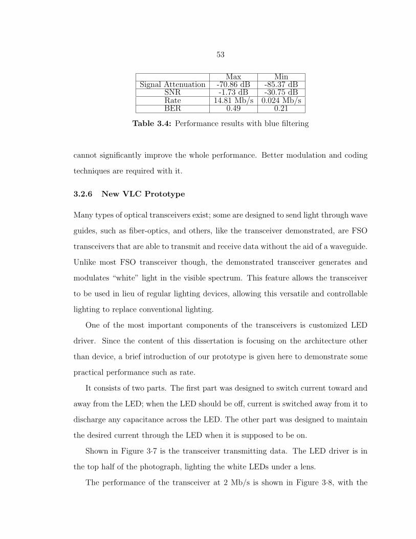
53
Max MinSignal Attenuation -70.86 dB -85.37 dB
SNR -1.73 dB -30.75 dBRate 14.81 Mb/s 0.024 Mb/sBER 0.49 0.21
Table 3.4: Performance results with blue filtering
cannot significantly improve the whole performance. Better modulation and coding
techniques are required with it.
3.2.6 New VLC Prototype
Many types of optical transceivers exist; some are designed to send light through wave
guides, such as fiber-optics, and others, like the transceiver demonstrated, are FSO
transceivers that are able to transmit and receive data without the aid of a waveguide.
Unlike most FSO transceiver though, the demonstrated transceiver generates and
modulates “white” light in the visible spectrum. This feature allows the transceiver
to be used in lieu of regular lighting devices, allowing this versatile and controllable
lighting to replace conventional lighting.
One of the most important components of the transceivers is customized LED
driver. Since the content of this dissertation is focusing on the architecture other
than device, a brief introduction of our prototype is given here to demonstrate some
practical performance such as rate.
It consists of two parts. The first part was designed to switch current toward and
away from the LED; when the LED should be off, current is switched away from it to
discharge any capacitance across the LED. The other part was designed to maintain
the desired current through the LED when it is supposed to be on.
Shown in Figure 3·7 is the transceiver transmitting data. The LED driver is in
the top half of the photograph, lighting the white LEDs under a lens.
The performance of the transceiver at 2 Mb/s is shown in Figure 3·8, with the

54
(a) PathLoss
x (m)
y (m
)
0 2 4 6 8 10 120
2
4
6
8
10
12
−84
−82
−80
−78
−76
−74
−72(b) SNR
x (m)
y (m
)
0 2 4 6 8 10 120
2
4
6
8
10
12
−30
−25
−20
−15
−10
−5
(c) MaxRate
x (m)
y (m
)
0 2 4 6 8 10 120
2
4
6
8
10
12
2
4
6
8
10
12
14(d) BER of OOK
x (m)
y (m
)
0 2 4 6 8 10 120
2
4
6
8
10
12
−0.65
−0.6
−0.55
−0.5
−0.45
−0.4
−0.35
Figure 3·6: Signal Attenuation (a), SNR (b), Max Rate (c) and BER(d) of the prototype system with blue filtering
transmitter input as the yellow signal and the receiver output as the green signal in
the oscilloscope. The left half shows the operation when the transceiver is idle with
the LEDs on and the right half shows data transmission.
3.3 DMT Analysis
Another important issue is the signaling design to improve the diffuse link model
performance. As we know, the main distortion that affects the channel is due to

55
Figure 3·7: Current VLC prototype for indoor applications [WCL11]
multiple copies from different paths, which is called multipath distortion. One of the
most efficient solutions is OFDM.
In OFDM, a large number of closely-spaced orthogonal sub-carriers are used to
carry data. The data is divided into several parallel data streams or channels, one
for each sub-carrier. Each sub-carrier is modulated with a conventional modulation
scheme at a low symbol rate, maintaining total data rates similar to conventional
single-carrier modulation schemes in the same bandwidth. Since it can mitigate ISI
arose by multipath distortion without complex equalization filter, OFDM is a good
solution for the multipath distortion in wireless optical communication, especially for
the indoor applications.
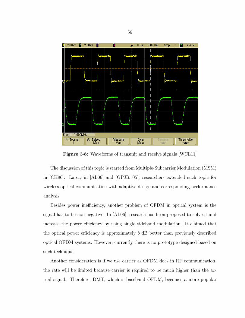
56
Figure 3·8: Waveforms of transmit and receive signals [WCL11]
The discussion of this topic is started fromMultiple-Subcarrier Modulation (MSM)
in [CK96]. Later, in [AL06] and [GPJR+05], researchers extended such topic for
wireless optical communication with adaptive design and corresponding performance
analysis.
Besides power inefficiency, another problem of OFDM in optical system is the
signal has to be non-negative. In [AL06], research has been proposed to solve it and
increase the power efficiency by using single sideband modulation. It claimed that
the optical power efficiency is approximately 8 dB better than previously described
optical OFDM systems. However, currently there is no prototype designed based on
such technique.
Another consideration is if we use carrier as OFDM does in RF communication,
the rate will be limited because carrier is required to be much higher than the ac-
tual signal. Therefore, DMT, which is baseband OFDM, becomes a more popular

57
Figure 3·9: Orthogonal Frequency Division Multiplexing [FK03]
candidate for FSO systems, and several prototypes have been demonstrated in Sec-
tion 2.2.1.
In this section, we give some fundamental researches on DMT to show in which
ways it can improve the VLC.
3.3.1 BER
BER is one of the most important parameters to measure. There are three general
types of interference. multipath distortion, negative signal chopping distortion and
ambient light shot noise. Since we consider AWGN model based on FSO without any
feedback loop, we assume a channel with Finite Impulse Response (FIR) as
y[k] = x[k] + 0.6x[k − 1]− 0.4x[k − 2] + 0.2x[k − 3]− 0.1x[k − 4] + 0.02x[k − 5].(3.1)
By using DMT, A high-speed binary serial input data sequence is divided into
N parallel lower-speed binary streams. For each stream indexed by n, where n =
0, 1, . . . , N − 1, every M number of bits are grouped together and mapped onto
complex values Cn according to a QAM constellation. Usually, a 2N -point Inverse
Fast Fourier Transform (IFFT) is used in the DMT transmitter to efficiently modulate
Cn into real value sequence onto N different channels. Therefore, the symbol after

58
0 5 10 15 20 25 30 35−2
−1
0
1
2Complex encoded signal
Rea
l Par
t
0 5 10 15 20 25 30 35−2
−1
0
1
2
Imag
inar
y P
art
Channel/Frequency
(a)
0 10 20 30 40 50 60 70−0.4
−0.2
0
0.2
0.4IFFT Modulated signal
Rea
l Par
t
0 10 20 30 40 50 60 70−1
−0.5
0
0.5
1
Imag
inar
y P
art
Time samples
(b)
0 10 20 30 40 50 60 700
0.1
0.2
0.3
0.4
0.5
0.6
0.7DC Offset Signal
Time samples
(c)
0 5 10 15 20 25 30 35−2
−1
0
1
2Signal after FFT and removal of mirrored data
Rea
l Par
t
0 5 10 15 20 25 30 35−2
−1
0
1
2
Imag
inar
y P
art
Channel/Frequency
(d)
Figure 3·10: (a) Encoded signal after QAM (b) Modulated signalafter IFFT (c) DC-offset signal before transmitting (d) Received signalafter FFT recovery
IFFT can be denoted as
u[k] =1√2N
2N−1∑n=0
Cnej2πn k
2N , k = 0, 1, . . . , 2N − 1. (3.2)
If we further take DC bias and prefix into consideration, the output of transmitter
will be
x[k] =1√2N
2N−1∑n=0
Cnej2πn
k−Np2N +D, k = 0, 1, . . . , 2N − 1 +Np, (3.3)

59
where Np denotes prefix length and D denotes the DC bias to avoid distortion by
cutting off the negative signal.
Similarly, at the receiver side, we shift the received symbol, y[k], back to zero bias
and then strip out the prefix. The symbol after FFT will be
Cn =
2N−1+Np∑k=Np
y[k]e−j2πnk−Np2N , n = 0, 1, . . . , 2N − 1. (3.4)
We demonstrate the process in a one-time DMT simulation which shown in Fig-
ure 3·10. In this simulation, 64 channels are assigned. 16 bits data are generated
randomly without particular bit loading scheme. Prefix length is five which can just
cover the all multi paths. QAM is used on each channel. It also shows in Fig-
ure 3·10(b) that the DMT modulated signal actually has zero imaginary part. Due
to the facts of no imaginary part and baseband modulation, high-frequency, analog
RF-components required for in-phase and quadrature-phase modulation are omitted
from DMT transceivers, reducing system costs and complexity.
Based on (3.1), (3.3) and (3.4), we demonstrate BER performance of DMT and
OOK in a multi-iteration simulation based on same parameters in the previous one-
time DMT simulation. In the simulation, three different DC offsets are considered to
overcome negative signal chopping distortion. The reason we choose DC offset solu-
tion is we are combining communication functionality with illumination functionality,
so the DC offset is inevitable to provide enough brightness to the entire room. In
Figure 3·10(c), we demonstrate the signaling process of DC-offset DMT solution. The
signal is chopped and reconstructed between transceivers, resulting in a few errors.
From Figure 3·11, although OOK can provide better result for small SNR, after
25 dB SNR, OOK can’t improve the BER into an acceptable level alone because of
the ISI from the multipath distortion. On the other hand, DMT is more vulnerable
to the noise. This is because instead of two level signal of OOK, multi-level signal

60
schemes have shorter minimum distance, and each symbol contains information of
multiple bits that one error symbol can result more than one errors in the original
signal. However, when SNR is higher enough, in this case it is 50 dB, DMT can
continue improve the BER performance.
Therefore, theoretically, by choosing great enough DC offset and long enough
prefix, BER of DMT can approach zero with the increase of SNR. From Section 2.1.4,
with a good signal filter at receiver side, good SNR is achievable by filtering out the
ambient noise.
0 10 20 30 40 50 600
0.1
0.2
0.3
0.4
0.5
0.6
0.7
SNR (dB)
BE
R
BER of DMT and OOK
DMT with DC=0.2
DMT with DC=0.25
DMT with DC=0.3
OOK
Figure 3·11: BER performance among different modulation schemes
61
3.3.2 Channel Capacity
Secondly, we give numerical results to show that DMT can indeed improve the chan-
nel. We here consider a simple in-door scenario with LOS link.
As is the case in RF transmission systems, multipath propagation effects are
important for wireless optical networks. However, there are some differences.
First, multipath fading is not a major impairment in wireless optical transmission.
This is mainly because the large size of the detector with respect to the wavelength of
the light provides a degree of inherent spatial diversity in the receiver which mitigates
the impact of multipath fading.
The second concern is the temporal dispersion of the received signal due to mul-
tipath propagation (mostly referred as multipath distortion). This distortion is often
modeled as a linear time invariant system since the channel properties change slowly
over many symbol periods [KKC95]. Indeed, channel models proposed for LOS links
assume the LOS path dominates and model the channel as a linear attenuation and
delay [CK97]. Furthermore, as a matter of fact, in a scenario with many LOS links
(as a typical office with multiple LED-based lamps), multipath distortion is seldom
an issue [Hra04] and the channel can be considered flat over the bandwidth of interest
[Hra04] [GRLW08b] [LGB+08] [VKN+09a].
Therefore, in the following analysis under the assumption of in-door LOS links,
without loss of generality, we consider h(t) = 1, which makes the channel into
y(t) = x(t) + n(t).
From information theory, we know that the channel capacity is given by mutual

62
information which is
I(x, y) = H(y)−H(n)
= −∞∫
−∞
fy(y) log2 fy(y)dy − 0.5 log2 4πσ2n, (3.5)
where H() denotes the entropy of corresponding signal and fy(y) is the Probability
Density Function (pdf) of the received signal samples. So, channel capacity depends
on the distribution of received signal, which is determined by the input signal. To
simplify the calculation, we set the constraint on average power of input optical signal
to 1,
P =
∞∫0
xfx(x)dx ≤ 1.
We have four candidates here for comparison. The first one is using OOK as
modulation scheme. The second one is using DMT without DC offset [AL06], the
third one is using DMT with 0.5 DC, and last one is the distribution which can
achieve maximum channel capacity. From Shannon’s theorem, when the constraint
is on the square of signal amplitude, the maximum channel capacity is achieved by
Gaussian input. So, from the relation between Gaussian distribution and exponential
distribution, the maximum channel capacity for optical channel should be achieved
by exponential input.
OOK
OOK is the simplest case among four schemes. If we consider 0, d with same proba-
bility in the data, then from power constraint, 0× 12+ d× 1
2= 1, which gives d = 2

63
for OOK. Therefore fy(y) of OOK is
fy(y) =1
2(N(0, σ2
n) +N(2, σ2n))
=1√8πσn
(e− y2
2σ2n + e
− (y−2)2
2σ2n ). (3.6)
DMT without DC
DMT is much more complicated than OOK scheme. In the traditional OFDM system,
the data to be transmitted is mapped onto a complex vector of length N , and then the
OFDM signal is generated by usingN point IFFT. Based on the central limit theorem,
if N is large enough, the outputs of the IFFT should have a Gaussian distribution.
However, in a FSO system with IM/DD, the signal must satisfy non-negative that
the transmitter will simply clip all the negative signals at 0. After that, the signal
distribution can be considered as 0 for half probability and Gaussian distribution for
the other half. From power constraint,
E(x) =
∞∫0
xfx(x)dx
=
∞∫0
x1√2πσ
e−x2
2σ2 dx
= 1,
we have σ =√2π.
In this way, the distribution of summation of signal and noise at receiver will be

64
the convolution of them, which is
fy(y) =1
2(fn(y) +
∞∫0
fx(x)fn(y − x)dx)
=1√8πσn
e− y2
2σ2n +
1
4π√2πσn
∞∫0
e−x2
4π− (y−x)2
2σ2n dx
=1√8πσn
e− y2
2σ2n +
1√8π(σ2
n + 2π)e− y2
4π+2σ2n erfc(−
√π
σ2n(2π + σ2
n)), (3.7)
where erfc() is complementary error function that equals to 2√π
∫∞x
e−t2dt.
DMT with DC
The third candidate is adding DC offset to make fewer signals being clipped that less
distortion will give to the receiver. Here we give a 0.5 offset. Then from
E(x) =
∞∫0
xfx(x)dx
=
∞∫0
x1√2πσ
e−(x−0.5)2
2σ2 dx
= 1,
we have σ = 1. Furthermore, we need to notice that
P (x = 0) =
0∫−∞
f(x)dx = 0.3085.
65
Let p = 0.3085. The received signal distribution will be
fy(y) = pfn(y) + (1− p)
∞∫0
fx(x)fn(y − x)dx
=p√2πσn
e− y2
2σ2n +
1− p
2πσn
∞∫0
e− (x−0.5)2
2− (y−x)2
2σ2n dx
=p√2πσn
e− y2
2σ2n +
1− p√8π(σ2
n + 1)e− (y−0.5)2
2+2σ2n erfc(− y + 0.5σ2
n
σn
√2 + 2σ2
n
). (3.8)
Exponential Distribution
For the last case, when the input follows exponential distribution,
E(x) =
∞∫0
xfx(x)dx
=
∞∫0
x1
ae−x/adx
= 1,
which gives a = 1.
Therefore the received signal distribution will be
fy(y) =
∞∫0
fx(x)fn(y − x)dx
=
∞∫0
1√2πσn
e−x− (y−x)2
2σ2n dx
=e−y+σ2
n/2
2erfc(
−y + σ2n√
2σn
). (3.9)
From the property of Gaussian noise, we have
σ2n = 10−
SNR10 . (3.10)

66
Putting back (3.6), (3.7), (3.8), (3.9) and (3.10) to (3.5), we therefore are able to
obtain channel capacities of these four cases with the computation of MATLAB.
Different from the simulation analysis in Section 3.3.1, the analysis here is theoretical
derivation. Figure 3·12 demonstrates the results in terms of different SNR.
0 5 10 15 20 25 30 35 400
1
2
3
4
5
6
7
SNR(dB)
Cha
nnel
Cap
acity
(bit/
s/H
z)
OOKOFDM with DC = 0.5OFDM without DCExponential
Figure 3·12: Channel capacities for four different cases under unitaverage power constraint
From the result, we can see that exponential distribution indeed gives us best
performance among all cases. Also OOK scheme has a maximum value of 1 which
matches the conclusion in [Hra04]. When SNR is smaller than 12 dB, DMT without
DC offset has better performance than DMT with DC offset. This is because it
has larger variance so that noise has less impact on it than the other DMT scheme.
However, when SNR is larger than 12 dB, the impact of noise is getting smaller.

67
Therefore, DMT with DC offset, which has less distortion due to fewer clipped signals,
becomes better than the other DMT scheme. But it is obvious that both DMT
schemes can greatly outperform OOK, which has been adopted very often due to its
energy efficiency and simplicity, in the way of potential rate can be achieved.
We conduct two different analyses on BER and channel capacity. The results
reveal that the tradeoff DMT faces is between rate and robustness. It can increase
the achievable rate, but faces great error performance under low SNR. These are
the reasons that most of high speed (≥ 100 Mb/s) VLC systems adopt DMT but
are limited their usage for short range indoor applications where good SNR is a fair
assumption.
3.4 Summary
In this chapter, we first discuss the modeling part of VLC for indoor scenarios. Based
on a signal attenuation model, we are able to predict the performance of several
different parameters. The results reveal the facts of using blue filtering technique and
establish a tool for performance analysis for any indoor VLC systems.
A general discussion on DMT also provides reason for adopting it in VLC. BER
performance shows DMT is able to reduce the error in high SNR cases where multi-
path distortion becomes more severe than noise, while OOK scheme alone can’t solve
multipath distortion. Furthermore, DMT can improve the channel capacity closing
to the optimum situation which is way better than OOK scheme can provide. The
analysis shows the tradeoff between rate and robustness under low SNR. Furthermore,
although DMT requires more cost on design comparing to OOK, it actually requires
less cost than OFDM due to the facts of baseband modulation and no imaginary part
in the transmitted symbols.

68
Chapter 4
Multi-hop Multi-access VLC Solution
In the chapter, we introduce our design on a multi-hop multi-access VLC solution. As
described in Section 1.2.3, there are two unique characteristics different from RF that
any VLC systems cannot ignore: LOS and directionality. Different from RF signal,
optical signal hardly penetrate most of objects in our daily life. And even the diffuse
lighting devices provide little lumen at the edge of their radiation patterns, which
results the directionality of optical signal. These characteristics are like double-edged
swords. They can favor certain performance such as rate and security, but they also
aggravate any problems on reliability, contention and coverage. In order to adopt VLC
in indoor scenarios and build a robust system, solving these problems is inevitable.
In this chapter, we propose a solution with two novel protocols and a novel scheme
working together at networking layer, and therefore, don’t require much modification
on physical layer. We demonstrate that by adopting them, not only the problems can
be solved, but also better performance can be achieved to meet the goals described
in Section 1.3.1, and more importantly, without any additional cost on more compre-
hensive signaling or device design, which indicates that the solution and the analysis
results can be also applied to other VLC systems and prototypes.
Furthermore, since in this solution, every device needs unique identification, IP
technique can be integrated to make the system compatible with other networks and
be able to have access to Internet.
There are two main parts of our proposed solution.
69
4.1 Networking Protocols for Blocking of Service Challenge
One of the most important characteristics of VLC is signal occlusion of the LOS
channels. As mentioned in Section 1.2.3, different from RF, although visible light is
more able to be reflected due to its larger refractive index than IR, both still suffer
from signal attenuation that can make the receive SNR very poor. And furthermore,
signal penetration of any non-transparent objects is physically impossible. We refer
this problem as blocking of service in this dissertation.
One proposed solution is MSD introduced in Section 2.1.5 with imaging diver-
sity receiver. It provides service by beaming the signal to the ceiling to form several
reflected light sources with Lambertian reflectance pattern. If a surface exhibits Lam-
bertian reflectance, light falling on it is scattered such that the apparent brightness
of the surface to an observer is the same regardless of the observer’s angle of view.
However, the source needs to be located at a desktop level, and fixed to provide stable
light sources. Therefore, any small change on the source location will be enlarged and
can greatly change the coverage pattern of the system. Besides, having a visible light
source at desktop level may cause annoyance for human eyes.
We present two network solutions for this problem through the use of relays for
data through other nodes or hosts, and have a comprehensive performance analysis
based on the assumption of CSMA/CA as MAC scheme. Also, a unique design of
receiver device is introduced to support one of these network solutions.
4.1.1 System Model
The general model and our goals have been introduced in Section 3.1.1 and Sec-
tion 1.3.1. In this section, we continue with more details.
Part of the user device is an extension from [YAKD09] while the rest of whole
system is an original design. Briefly, the system is comprised of two layers, ceiling

70
level base station and desktop level user device. The base station has access to the
backbone network through traditional wired or wireless communications. It collects
requests from user devices under its coverage and then provides services accordingly
so that bridging user devices with Internet. Figure 4·1 demonstrates the architecture.
Base Station
The base station is equipped with diffuse transmitter and wide FOV receiver. The
reason is it needs to provide access points to multiple users below it in a large area,
and also, for illumination, the ceiling level lamp has to be a wide diffuse link model
for optical signal. Based on the design of illumination device, the white light of the
lamp is comprised by three different color LEDs, red, green and blue. First of all,
this property gives the system ability to simply achieve multiple services by grouping
different service users with one same color LED for communication. The base station
modulates different color LEDs separately based on different service requirement that
they can transmit data exclusively and simultaneously without interfering each other.
In simple words, it can introduce more diversity simply and directly. The receiver of
base station still uses traditional photon-detector for IR spectrum. The reason is due
to the user device which is discussed in Section 4.1.1. However, due to diffuse link and
wide FOV, sophisticated signaling techniques are required to combat adverse effects,
which are out of scope of this dissertation.
User Device
The design of desktop level user device is much more complicated since it is responsible
for both communication between other user device and base station. The fundamental
shape of the device is hexagonal cylinder which is shown in Figure 4·2. The original
idea is a honeycombed sphere which comes from [YAKD09]. However, this design is
not suitable for us.
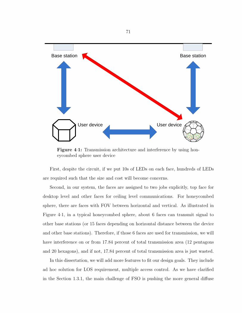
71
User device User device
Base station Base station
Figure 4·1: Transmission architecture and interference by using hon-eycombed sphere user device
First, despite the circuit, if we put 10s of LEDs on each face, hundreds of LEDs
are required such that the size and cost will become concerns.
Second, in our system, the faces are assigned to two jobs explicitly, top face for
desktop level and other faces for ceiling level communications. For honeycombed
sphere, there are faces with FOV between horizontal and vertical. As illustrated in
Figure 4·1, in a typical honeycombed sphere, about 6 faces can transmit signal to
other base stations (or 15 faces depending on horizontal distance between the device
and other base stations). Therefore, if those 6 faces are used for transmission, we will
have interference on or from 17.84 percent of total transmission area (12 pentagons
and 20 hexagons), and if not, 17.84 percent of total transmission area is just wasted.
In this dissertation, we will add more features to fit our design goals. They include
ad hoc solution for LOS requirement, multiple access control. As we have clarified
in the Section 1.3.1, the main challenge of FSO is pushing the more general diffuse
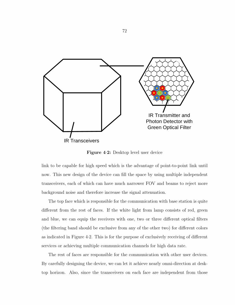
72
IR Transceivers
IR Transmitter and Photon Detector with Green Optical Filter
Figure 4·2: Desktop level user device
link to be capable for high speed which is the advantage of point-to-point link until
now. This new design of the device can fill the space by using multiple independent
transceivers, each of which can have much narrower FOV and beams to reject more
background noise and therefore increase the signal attenuation.
The top face which is responsible for the communication with base station is quite
different from the rest of faces. If the white light from lamp consists of red, green
and blue, we can equip the receivers with one, two or three different optical filters
(the filtering band should be exclusive from any of the other two) for different colors
as indicated in Figure 4·2. This is for the purpose of exclusively receiving of different
services or achieving multiple communication channels for high data rate.
The rest of faces are responsible for the communication with other user devices.
By carefully designing the device, we can let it achieve nearly omni-direction at desk-
top horizon. Also, since the transceivers on each face are independent from those

73
on other faces, simultaneous communication can be enabled between multiple user
devices. Furthermore, since the omni-direction is covered by multiple faces, the link
model is approximately point-to-point (quasi-point-to-point) and the FOV is much
narrower than the top face. This advantage can greatly reduce multipath distortion
and background light noise so that the transceiver design is much simpler. However,
angle diversity is achieved with the expense of spatial reuse.
Generally, we still use IR transceivers for the faces other than top face and IR
transmitter for the top face. This is because in a real situation, multiple visible
light sources at desktop level could be very disturbing to human eyes. RF could
still be a choice, but we can reuse some of the existing optical components for the
communication with the base station that we can simplify the design and save some
cost. By sticking with IR, the searches could be also very general in the FSO area.
Another great advantage of the user device is it can support certain degree of
mobility and solve the LOS blocking problem which is especially important for point-
to-point link model. When the face lost LOS of its communication object, the user
device will automatically trigger a searching procedure and resume transmission after
reconstruction of the data link.
In [YAKD09], researchers did intensive analysis on coverage and range. In this dis-
sertation we provide analysis on connectivity performance and available throughput
in Section 4.1.3.
4.1.2 Networking Protocols
Because of the inherent property of light mentioned before, LOS is required to provide
continuous connectivity. Although signal reflection still exists, this configuration
suffers from a high signal attenuation due to the absence of a direct path and data-
rate limitation caused by reflections. This latter limitation results from multipath
74
distortion caused by different paths (including reflections off of walls and ceiling) the
signal takes to travel to a receiver [AK03].
Considering the scenario in Figure 3·2, there are two possible solutions for this
problem. Each of them has its advantages and disadvantages which make them
suitable for different application scenarios.
Peer-to-Peer Protocol
Wireless ad-hoc networks has been widely studied with multihop and even multicast
for years in the area of RF. However, regularly, in free space optical, since there
is no omni-direction signal, most of existing protocols and solutions cannot simply
apply directly to our research. Our architecture gives us opportunities to change the
situation.
The first protocol achieves the goal of solving blocking by exploring the possibility
of peer-to-peer communication among user devices. It is very similar to the research
of wireless sensor networks in RF area. Basically, when blocking happens between
two nodes, the source node will start a search procedure through other nodes in the
network to find a multihop path. However, since the device has multiple faces, each of
which can send data independently, the procedure and information required are very
different from the routing protocols in RF. The procedure is introduced as following
in brief:
1. When connection between two nodes is interrupted, the source node will first
check all other faces that if destination node exists in the LOS of any of them.
If yes, nodes can reestablish the link through new faces on both devices. If not,
that means the interrupt is due to either out of range or blocking, both of them
require additional steps. In the meantime, the destination node will also update
its local neighbor table by sending out Neighbor Discovery Packet (NDP) with
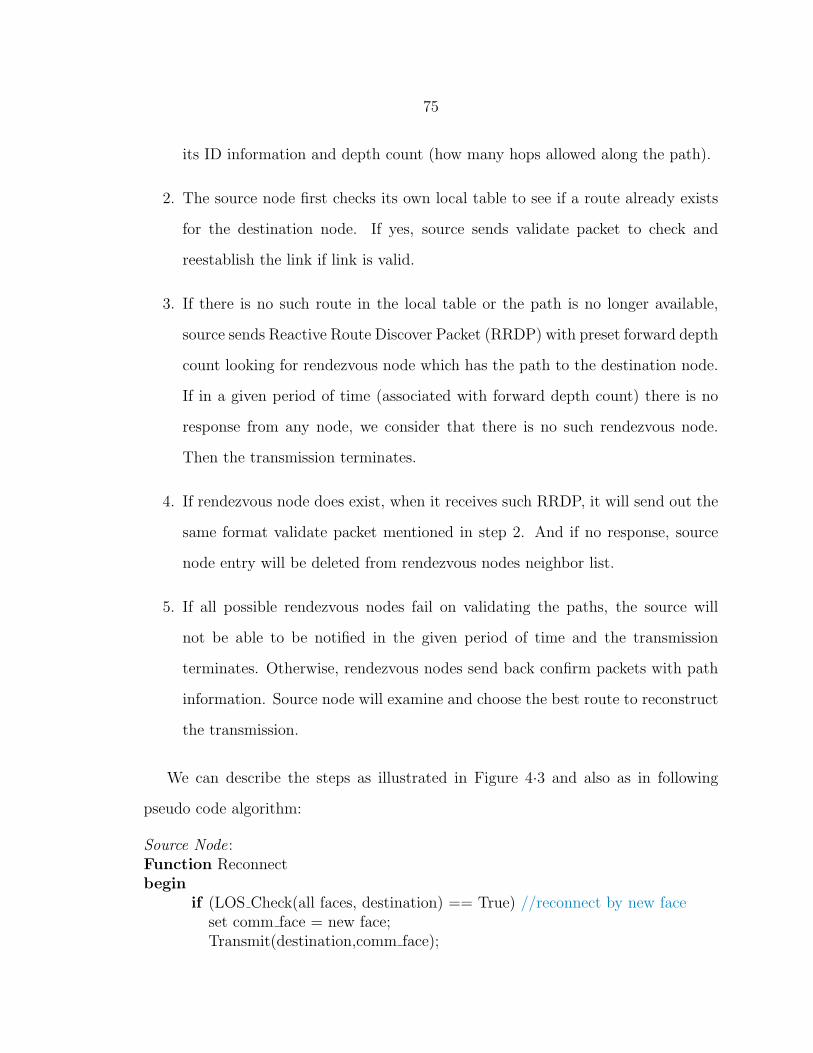
75
its ID information and depth count (how many hops allowed along the path).
2. The source node first checks its own local table to see if a route already exists
for the destination node. If yes, source sends validate packet to check and
reestablish the link if link is valid.
3. If there is no such route in the local table or the path is no longer available,
source sends Reactive Route Discover Packet (RRDP) with preset forward depth
count looking for rendezvous node which has the path to the destination node.
If in a given period of time (associated with forward depth count) there is no
response from any node, we consider that there is no such rendezvous node.
Then the transmission terminates.
4. If rendezvous node does exist, when it receives such RRDP, it will send out the
same format validate packet mentioned in step 2. And if no response, source
node entry will be deleted from rendezvous nodes neighbor list.
5. If all possible rendezvous nodes fail on validating the paths, the source will
not be able to be notified in the given period of time and the transmission
terminates. Otherwise, rendezvous nodes send back confirm packets with path
information. Source node will examine and choose the best route to reconstruct
the transmission.
We can describe the steps as illustrated in Figure 4·3 and also as in following
pseudo code algorithm:
Source Node:Function Reconnectbegin
if (LOS Check(all faces, destination) == True) //reconnect by new faceset comm face = new face;Transmit(destination,comm face);
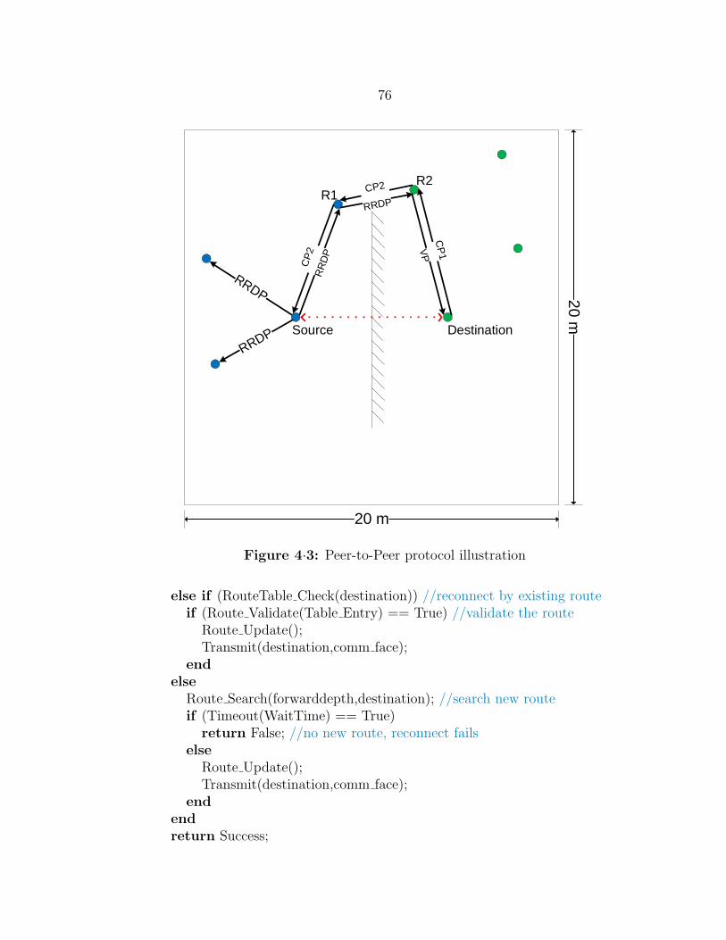
76
CP
2R
RD
P
CP2
RRDP
RRDP
CP
1
Source Destination
R1R2
20 m
20 m
RRDP
VP
Figure 4·3: Peer-to-Peer protocol illustration
else if (RouteTable Check(destination)) //reconnect by existing routeif (Route Validate(Table Entry) == True) //validate the route
Route Update();Transmit(destination,comm face);
endelse
Route Search(forwarddepth,destination); //search new routeif (Timeout(WaitTime) == True)
return False; //no new route, reconnect failselse
Route Update();Transmit(destination,comm face);
endendreturn Success;

77
end
Rendezvous Node:Function Relaybegin
if (PacketType == Data) //forward data packet[NextNode,face] = RouteTable Check(destination);Transmit(NextNode,face);
elseif (TTL != 0)
if (RouteTable Check(destination) == True) //check own neighbor listif (Route Validate(Table Entry) == True)
Route Confirm(source); //send back confirm with new routeelse
return False; //drop request and invoke neighbor updateend
elseFlood(packet,TTL-1); //if not in neighbor, forward request
endend
endreturn Success;
end
The formats of six packets used in the steps are shown in the Table 4.1. Time to
Live (TTL) is required to prevent message flooding. They are actually the same with
depth counts introduced in the previous procedure steps. Inter-nodes means all the
nodes along the path of that message traveled.
NDP [TTL1(hop #), previous id(prevent loop), source id]RRDP [TTL2(hop #), all inter-nodes, source id, destination id]
Local Table [source id, hop #, face #, next node id]Validate Packet [destination id, hop #]Confirm Packet 1 [check]Confirm Packet 2 [The final TTL2(hop #), all inter-nodes(include ren-
dezvous node), hop # from rendezvous node table]
Table 4.1: Packet format of Peer-to-Peer protocol
The reconnectivity justification of the protocol will be presented in Section 4.1.3.

78
Peer-to-Host Protocol
The other protocol includes hosts and the base stations at the ceiling level in our
system for relaying the data. We consider the network as a two-layer geometry; nodes
and base stations. Between every two peer nodes, there is only direct transmission
and no multihop. Otherwise, the source node has to go through the host(s) to reach
the destination node. We consider this in detail in the following steps.
1. The first step is very similar to that of the peer-to-peer protocol. The source
node will first try to find alternative direct contact with destination node
through other faces, and reestablish the link through new faces on both de-
vices if available.
2. If there is no direct contact, source node will send a Source-to-Host (StoH)
packet to its own host (Host A). The host then checks its node list to find out
if the destination node is also under its coverage. If yes, a validate packet will
be sent to check the availability.
3. If destination node is not in the list or there is no confirmation, host A will send
out a similar request, Host-to-Host (HtoH) packet, to all its neighbor hosts in
the local network (for example, all other ceiling lamps in the same office room).
4. Every peer host will check its own node list based on the information in HtoH.
If the destination node exists, the corresponding host (Host B) will also need
to check the link validation.
5. Similarly, if in a given period of time no response is sent back due to either no
host has destination node in list or the link no longer exists, we consider the
transmission terminated. Otherwise, the destination node will confirm the link

79
to B, and then B will confirm to A and source node, so that the link can be
reestablished.
A
HtoH(wired)
HtoH
(wired)
B
Destination
Source
20 m
20 m
HtoH(wired)
StoH
CP2
VP
CP
1
Figure 4·4: Peer-to-Host protocol illustration (cluster heads aremarked with red)
Similarly, we can describe the steps as illustrated in Figure 4·4 and also as in
following pseudo code algorithm:
Source Node:Function Reconnectbegin
if (LOS Check(all faces, destination) == True) //reconnect by new faceset comm face = new face;Transmit(destination,comm face);

80
elseRoute Search(destination); //search route through hostsif (Timeout(WaitTime) == True)
return False;//no new route, reconnect fails
elseRoute Update();Transmit(destination,topface);
endend
end
Host :Function Relaybegin
if (PacketType == Data) //forward data packetNextNode = RouteTable Check(destination);Transmit(NextNode);
elseif (TTL != 0)
if (NodeList(destination) == True) //check own node listif (Node Validate(destination) == True)
Node Confirm(source);//send back confirm with new routeelse
return False; //drop request and invoke node updateend
elseFlood(packet,1); //if not in coverage, forward request to other hosts
endend
endreturn Success;
end
The formats of six packets used in the steps are shown in the Table 4.2.
The reconnectivity justification of the protocol will be presented in Section 4.1.3.
4.1.3 Connectivity and Rate Performance Analysis
We first discuss reconnectivity performance by simulations.

81
StoH [source id, destination id]HtoH [destination id, source id, Host A id]
Host Table [node id, channel id(if FDMA), PN code(if DSSS)]Validate Packet [destination id]Confirm Packet 1 [check]Confirm Packet 2 [Host B id, Host A id]
Table 4.2: Packet format of Peer-to-Host protocol
We consider a scenario of 20 m by 20 m room. The forward depth count is set
to 2, and the neighbor depth count is set to 1. The communication range is a radius
of 10 m. We iterate 10,000 times. The transmission is between two nodes located
at (6,10) and (14,10). The block is a wall from (10,4) to (10,16). We calculate a
Reconnectivity Success Ratio for different numbers of users.
Also in the scenario, we put 4 hosts and the coverage radius of each host of 5 m,
corresponding to one fourth of the room side length. All nodes are deployed randomly
in the room.
The third protocol we consider here is a hybrid solution by having both protocols
we have introduced. If the peer-to-peer protocol fails to find a route, the peer-to-host
protocol will be activated. The solution fails only if both protocols fail.
The two scenarios are also illustrated in Figure 4·3 and Figure 4·4.
Figure 4·5 shows that the peer-to-peer protocol needs more nodes to achieve high
reconnectivity successful ratio. When the number of users reaches 20, the ratio is
close to 90 %. On the other hand, peer-to-host protocol has a stable reconnectivity
successful ratio, mainly due to the fact that in this protocol the successful reconnection
only depends on if both two nodes are under the coverage of 4 hosts. The hybrid
solution can greatly increase the performance, and therefore is the best choice in
terms of reconnectivity.
However, the good performances of hybrid solution and peer-to-peer protocol for
more nodes come with a price. Both increase additional overheads that burden the

82
2 4 6 8 10 12 14 16 18 200
0.1
0.2
0.3
0.4
0.5
0.6
0.7
0.8
0.9
1
n
Rec
onne
ctiv
ity p
roba
bilit
y
peer−to−peerpeer−to−hosthybrid
Figure 4·5: Reconnectivity success ratio of p2p, p2h and hybrid pro-tocols
system. For the peer-to-peer protocol, the overheads to the whole network equals
AverageEntry ∗∑forwarddepth−1
k=0 (AverageEntry − 1)k. For example, in our simula-
tion, when there are 20 users, the average entry is 7.67 neighbors, which makes the
overheads as high as 58.7 routing packets. While on the other hand, peer-to-host
protocol only requires limited overheads to find the path through hosts (the burden
to the whole network is always 1). And since hosts are fixed infrastructures, none
of these overheads are required to be flooded to the network. Similarly, the burden
to each node is the entry amount in the neighbor table. In our simulation, we only
consider one depth neighbor which has an average of 7.67 neighbors for 20 users. If
the depth becomes 2, this burden will be 13.1 neighbors which is greatly increased

83
with the change of such depth count.
In Chapter 4.2, we propose a new MAC scheme. Here we just use existing scheme
for simplicity. There are several solutions for multiple access. However, the user
device is normally expected to be small. Therefore, the technique used for uplink and
node to node communication should be simple scheme with easy implementation. A
good choice is CSMA/CA. It is one of the most popular schemes for MAC and it has
been used in 802.11 based Wireless Local Area Networks (WLAN). The hidden node
problem can be solved by its extension with hand-shaking protocol.
However, since it is not simultaneous access and there is still chance of collision,
the real rate is actually lower than the system capacity. In [Bia00], the author pre-
sented a theoretical model for CSMA/CA. By using this model and customizing it
to our specific architecture, we can identify the packet transmission probability, τ ,
and conditional collision probability, p. Considering a CSMA/CA with a contention
window of W and maximum backoff stage of m, from [Bia00] we have
τ =2(1− 2p)
(1− 2p)(W + 1) + pW (1− (2p)m). (4.1)
We consider the worst case that every node always has a packet to deliver. For
the uplink of node to host communication, if more than one node chooses the current
time slot to transmit, collision will occur at the host. So, for n nodes,
p = 1− (1− τ)n−1. (4.2)
For node-to-node (p2p) communication, the analysis is more complex. We know
that the user device has six faces, so the transmission from nodes which are not
within the FOV of face sending the packet are not going to interfere. Even for the
node within that FOV, if they don’t have packet to transmit at the same time slot,

84
the collision will not occur. Therefore, the new collision probability is
p = 1−n−1∑k=0
(n− 1
k
)(5
6)n−1−k(
1
6(1− τ))k
= 1− (1− 1
6τ)n−1.
By solving these two formulas we are able to have a unique pair of results for τ, p.
Before evaluating the throughput, we need to define the time variables. Based on
802.11 MAC specifications, we set them as in Table 4.3.
Table 4.3: Time variables definition [Bia00]Payload size 8184 bitsMAC header 272 bitsPHY header 128 bits
ACK 112 bits + PHY headerRTS 160 bits + PHY headerCTS 112 bits + PHY header
Propagation delay (δ) 1 µsSlot time (σ) 50 µs
SIFS 28 µsDIFS 128 µs
There are three cases for any time in the transmission procedure; empty time slot
when every node is in the backoff contention window, failed transmission (require
time length of Tfail) when there are more than one nodes sending out the Request to
Send (RTS), and successful transmission (require time length of Tsucc) when only one
node is trying to send out the RTS. Therefore, based on CSMA/CA scheme, reference
[Bia00] shows
Tsucc=RTS
rate+ SIFS + δ +
CTS
rate+ SIFS + δ +
Header
rate
+Payload
rate+ SIFS + δ +
ACK
rate+DIFS + δ,
Tfail=RTS
rate+DIFS + δ.
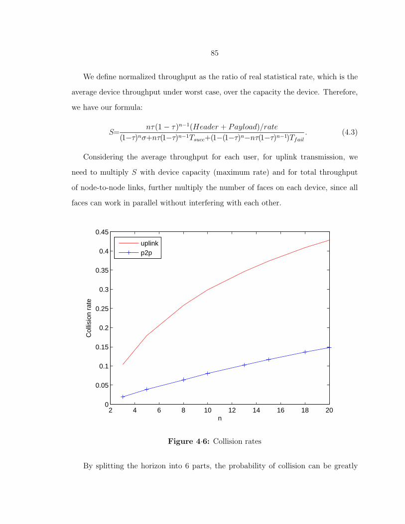
85
We define normalized throughput as the ratio of real statistical rate, which is the
average device throughput under worst case, over the capacity the device. Therefore,
we have our formula:
S=nτ(1− τ)n−1(Header + Payload)/rate
(1−τ)nσ+nτ(1−τ)n−1Tsucc+(1−(1−τ)n−nτ(1−τ)n−1)Tfail
. (4.3)
Considering the average throughput for each user, for uplink transmission, we
need to multiply S with device capacity (maximum rate) and for total throughput
of node-to-node links, further multiply the number of faces on each device, since all
faces can work in parallel without interfering with each other.
2 4 6 8 10 12 14 16 18 200
0.05
0.1
0.15
0.2
0.25
0.3
0.35
0.4
0.45
n
Col
lisio
n ra
te
uplinkp2p
Figure 4·6: Collision rates
By splitting the horizon into 6 parts, the probability of collision can be greatly

86
2 4 6 8 10 12 14 16 18 200
0.1
0.2
0.3
0.4
0.5
0.6
0.7
0.8
0.9
1
n
Nor
mal
ized
thro
ughp
ut o
f sys
tem
1Mbps(uplink)2Mbps(uplink)5Mbps(uplink)10Mbps(uplink)1Mbps(p2p)2Mbps(p2p)5Mbps(p2p)10Mbps(p2p)
Figure 4·7: Normalized throughput of system
reduced as shown in Figure 4·6. This is because the area can introduce collisions has
been reduced to one sixth.
In Figure 4·7, the node-to-node protocol, however, doesn’t give much efficiency
boost over uplink transmission. This is because τ is not very large so that its increase
does not substantially improve the overall system performance. Also, we see that
high speed can result low efficiency since the time ratio of payload will be decreased
by increasing the rate.
Even though, due to the parallel transmission ability, the user throughput can
still be greatly improved. We consider the rate capacities for uplink and node-to-
node transmission to be 2 Mb/s and 10 Mb/s respectively. In Figure 4·8, the result
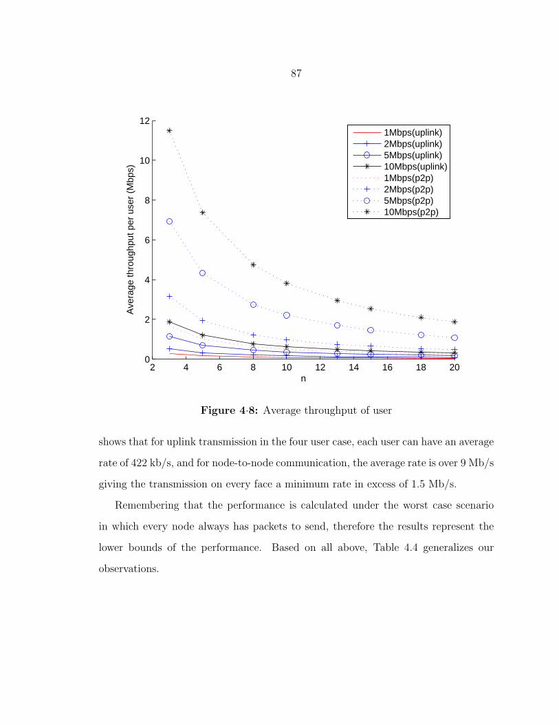
87
2 4 6 8 10 12 14 16 18 200
2
4
6
8
10
12
n
Ave
rage
thro
ughp
ut p
er u
ser
(Mbp
s)
1Mbps(uplink)2Mbps(uplink)5Mbps(uplink)10Mbps(uplink)1Mbps(p2p)2Mbps(p2p)5Mbps(p2p)10Mbps(p2p)
Figure 4·8: Average throughput of user
shows that for uplink transmission in the four user case, each user can have an average
rate of 422 kb/s, and for node-to-node communication, the average rate is over 9 Mb/s
giving the transmission on every face a minimum rate in excess of 1.5 Mb/s.
Remembering that the performance is calculated under the worst case scenario
in which every node always has packets to send, therefore the results represent the
lower bounds of the performance. Based on all above, Table 4.4 generalizes our
observations.

88
Table 4.4: Comparison of two protocolsPerformance Peer-to-peer Peer-to-hostComplexity High LowOverhead High LowMobility Low MediumSpeed High Low
Interference Low HighBurden to Host No Yes
Outdoor Extension Yes No
4.2 Centralized Optical MAC Scheme
For any WLAN, multiple access is always a very important feature. Due to the low
complexity and low cost requirements, most indoor wireless systems adopt simple
MAC schemes. CSMA/CA is one of the most popular schemes for MAC and it has
been used in 802.11 based WLANs. Although it still faces problems like mask-node
problem, under most of cases it can provide satisfactory performance with minimum
complexity.
As we mentioned, directionality is another important characteristic of VLC. Dif-
fuse link suffers from high signal attenuation, especially at the edge of the coverage.
Therefore, most of VLC systems which expect high rate transmission cannot have
large single coverage and FOV, and they need multiple light sources to cover a large
area, such as a conference room. This not only raises the question on how to smoothly
switch from one access point to another, but also brings a new multi-access contention
problem which omni-directional RF signal doesn’t face.
We start with the discussion on CSMA/CA and other existing MAC solutions.
Then, a new MAC scheme is provided with performance analysis. The conclusion is
given at the end of chapter for an overall comparison.

89
4.2.1 Problem Definition
As mentioned, in VLC, the scenarios are different from RF systems. First, the di-
rectionality of optical signal makes channel sensing becoming much more difficult in
FSO. Second, due to high signal attenuation at the edge of the illumination pattern,
the coverage of the transceiver is greatly limited. Together, that means, any scenar-
ios with mobility face more challenges from handling access point switch, resource
allocation, user management and contention interference.
Figure 4·9: Illustration of MAC scenario
Based on our project goals described in Section 1.3.1, we define our user scenario
as follows, which is also illustrated in Figure 4·9:
• We continue considering indoor applications for office use with multiple light
sources (access point) to provide illumination and communication to the user
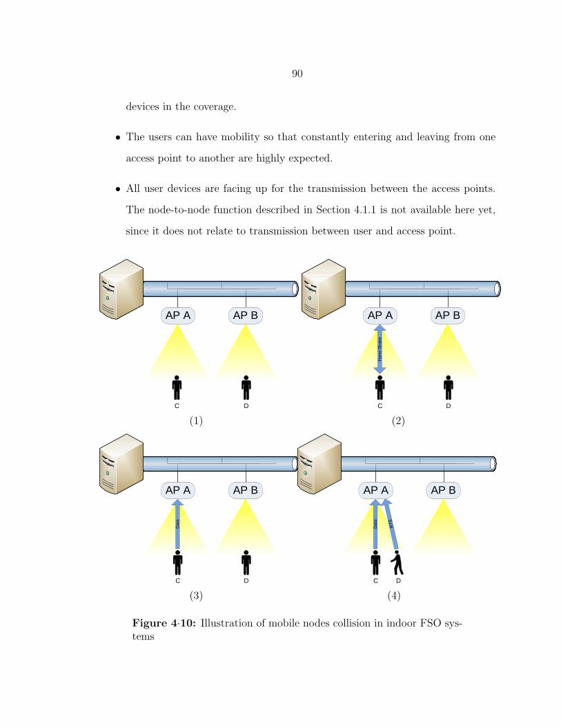
90
devices in the coverage.
• The users can have mobility so that constantly entering and leaving from one
access point to another are highly expected.
• All user devices are facing up for the transmission between the access points.
The node-to-node function described in Section 4.1.1 is not available here yet,
since it does not relate to transmission between user and access point.
AP A AP B
C D
(1)
AP A AP B
DC
Han
d S
hake
(2)
AP A AP B
DC
Dat
a
(3)
AP A AP B
C
Dat
a
RT
S
D
(4)
Figure 4·10: Illustration of mobile nodes collision in indoor FSO sys-tems

91
Therefore, we see that the user device has no access to other nodes’ transmission
status. Figure 4·10 demonstrates the collision due to this unique characteristic of
indoor FSO system. We explain the simple two access points scenario in Figure 4·10
as follows:
1. Initially, there are two users, C and D, belonging to different access points, A
and B. And both are static for now.
2. User C starts a new transmission request to its access point A with standard
hand-shaking procedure.
3. After the successful hand-shaking, user C starts uploading data through access
point A.
4. In the mean time, user D starts moving from its original access point B to
the new access point A with either an undergoing transmission or a planning
transmission. However, since user D’s FOV does not cover user C, it cannot
sense the channel usage situation in the coverage of access point A. Therefore,
any packet from user D will cause collision at the access point A.
4.2.2 Existing MAC Solutions
As we have mentioned, there are several choices for low complexity, low cost MAC
schemes for indoor applications. We briefly introduce and discuss their feasibility in
our VLC system here.
CSMA/CA
The unique problem we are trying to solve is actually not a problem for CSMA/CA in
RF. This is due to the fact that all packets (RTS, Clear to Send (CTS), Data, ACK)
are sent omni-directionally. Whatever status (RTS, CTS, Data transmitting or idle)
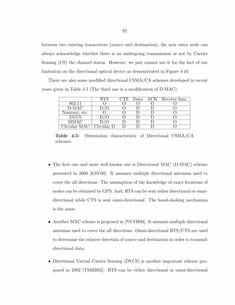
92
between two existing transceivers (source and destination), the new enter node can
always acknowledge whether there is an undergoing transmission or not by Carrier
Sensing (CS) the channel status. However, we just cannot use it for the fact of our
limitation on the directional optical device as demonstrated in Figure 4·10.
There are also some modified directional CSMA/CA schemes developed in recent
years given in Table 4.5 (The third one is a modification of D-MAC).
RTS CTS Data ACK Receive func.802.11 O O O O OD-MAC D/O O D D O
Nasiouri, etc. O O D D ODVCS D/O D D D OMMAC D/O D D D O
Circular-MAC Circular D D D D O
Table 4.5: Orientation characteristic of Directional CSMA/CAschemes
• The first one and most well-known one is Directional MAC (D-MAC) scheme
presented in 2000 [KSV00]. It assumes multiple directional antennas used to
cover the all directions. The assumption of the knowledge of exact locations of
nodes can be obtained by GPS. And, RTS can be sent either directional or omni-
directional while CTS is sent omni-directional. The hand-shaking mechanism
is the same.
• Another MAC scheme is proposed in [NYYH00]. It assumes multiple directional
antennas used to cover the all directions. Omni-directional RTS/CTS are used
to determine the relative direction of source and destination in order to transmit
directional data.
• Directional Virtual Carrier Sensing (DVCS) is another important scheme pro-
posed in 2002 [TMRB02]. RTS can be either directional or omni-directional
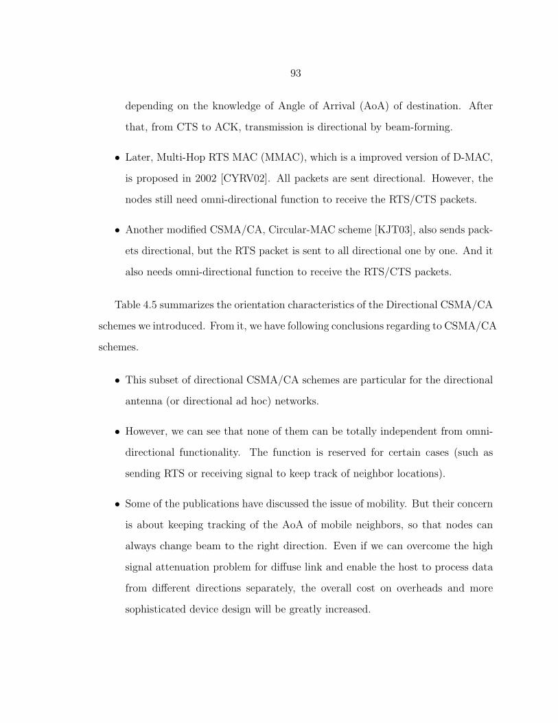
93
depending on the knowledge of Angle of Arrival (AoA) of destination. After
that, from CTS to ACK, transmission is directional by beam-forming.
• Later, Multi-Hop RTS MAC (MMAC), which is a improved version of D-MAC,
is proposed in 2002 [CYRV02]. All packets are sent directional. However, the
nodes still need omni-directional function to receive the RTS/CTS packets.
• Another modified CSMA/CA, Circular-MAC scheme [KJT03], also sends pack-
ets directional, but the RTS packet is sent to all directional one by one. And it
also needs omni-directional function to receive the RTS/CTS packets.
Table 4.5 summarizes the orientation characteristics of the Directional CSMA/CA
schemes we introduced. From it, we have following conclusions regarding to CSMA/CA
schemes.
• This subset of directional CSMA/CA schemes are particular for the directional
antenna (or directional ad hoc) networks.
• However, we can see that none of them can be totally independent from omni-
directional functionality. The function is reserved for certain cases (such as
sending RTS or receiving signal to keep track of neighbor locations).
• Some of the publications have discussed the issue of mobility. But their concern
is about keeping tracking of the AoA of mobile neighbors, so that nodes can
always change beam to the right direction. Even if we can overcome the high
signal attenuation problem for diffuse link and enable the host to process data
from different directions separately, the overall cost on overheads and more
sophisticated device design will be greatly increased.

94
VLC MAC
There are also several researches on MAC particularly for VLC.
• Inter-MAC We have introduced OMEGA project in Section 2.2.1. Besides the
researches on developing prototypes, they also presented their work on MAC.
As described, in OMEGA project, multiple technologies have been integrated
together to provide seamlessly transmission for different purposes. In order
to achieve its objectives, the OMEGA project needs a technology independent
MAC layer (named Inter-MAC) to control this network and provide services as
well as connectivity to any number of devices the user wishes to connect to it
in any room in a house/apartment, and further, this layer will allow the service
to “follow the user” from device to device [OME].
Figure 4·11: The superframe structure of Inter-MAC [OME]
In Inter-MAC, timeline is divided into superframe as illustrated in Figure 4·11.
The superframe duration is 67.108864 ms. The superframe is composed of 1024
Time Slots, and the first 64 time slots are considered as beacon period which
is used for synchronization and reservation request. The rest time slots are
used for data transmission reservation. It requires a device to scan for beacons

95
for at least two superframes before it transmits any frames. Therefore, it has
a minimum latency of 134 ms under the cases of no collision for messages in
beacon period.
However, Inter-MAC is designed for high speed wireless applications (the time
slots duration can be chosen for data rates varying from 128 to 1024 Mb/s).
This is not included in the scenarios or applications we described in Section 1.3.1
and required support of better transceiver. Furthermore, when link is estab-
lished in one superframe, it does not require additional beacons during following
superframes with data transmission. If device stops the transmission due to the
reason such as out of coverage, it will continue keeping the reservations which
therefore compromise the throughput. Because of these characteristics, Inter-
MAC is not a good choice for applications with mobility or rate lower than 128
Mb/s, and therefore will not be included into our analysis.
• Optical CSMA/CD
The system presented in [LIH09] demonstrates another way to use CSMA
scheme. Basically, before sending out RTS, the user with task first detects
the channel for any carrier being transmitted. After receiving the RTS (or
corrupted packet by collision), the access point repeats the packet back to all
users, and if the packet isn’t consilient with RTS or other users’ uploading data
packet, this indicates a collision occurs at the access point.
However, it is not clear that when the access point should consider a packet
as corrupted packet from collision and repeat back. And the assumption of
detecting any carrier being transmitted makes the system very vulnerable to
noises. The host could consider noise as corrupted packet and reply back to the
whole network and therefore compromise the throughput.
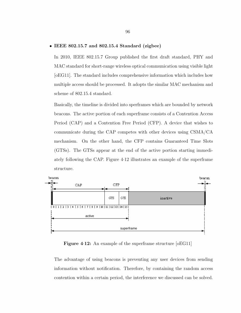
96
• IEEE 802.15.7 and 802.15.4 Standard (zigbee)
In 2010, IEEE 802.15.7 Group published the first draft standard, PHY and
MAC standard for short-range wireless optical communication using visible light
[oEG11]. The standard includes comprehensive information which includes how
multiple access should be processed. It adopts the similar MAC mechanism and
scheme of 802.15.4 standard.
Basically, the timeline is divided into sperframes which are bounded by network
beacons. The active portion of each superframe consists of a Contention Access
Period (CAP) and a Contention Free Period (CFP). A device that wishes to
communicate during the CAP competes with other devices using CSMA/CA
mechanism. On the other hand, the CFP contains Guaranteed Time Slots
(GTSs). The GTSs appear at the end of the active portion starting immedi-
ately following the CAP. Figure 4·12 illustrates an example of the superframe
structure.
active
superframe
Figure 4·12: An example of the superframe structure [oEG11]
The advantage of using beacons is preventing any user devices from sending
information without notification. Therefore, by containing the random access
contention within a certain period, the interference we discussed can be solved.

97
However, there are several disadvantages:
1. The lengths of superframe and its periods are fixed. A device transmitting
within the CAP shall ensure that its transaction is complete before the
end of the CAP. If this is not possible, the device shall defer its transmis-
sion until the CAP of the following superframe and the remaining of the
CAP will be idle state. This inefficiency becomes one drawback of system
throughput.
2. New enter user device can only access the base station within CAP. The
CAP shall shrink or grow dynamically to accommodate the size of the
CFP. Therefore, the number of new enter user devices is limited. This
means the new enter user device shall expect long delay to connect to the
base station.
3. The base station will not keep track of all user devices’ status for every
superframe. If one leaves the coverage without any notice and it has been
allocated with GTS, base station will keep this useless GTS for several
superframe, which becomes another drawback of system throughput. Also,
not keeping updates in every superframe can make the scheme not ideal
for scenarios requiring high security or continuous tracking.
4.2.3 Proposed COMAC Scheme
We have revealed the contention problem of VLC. From here on, we present our novel
MAC scheme which we call it Centralized Optical MAC (COMAC). The fundamental
principles are still four-way hand-shaking with backoff mechanism. And, it shares
similarities with MAC specifications of 802.15.7 standard so that it is also capable
of solving the contention. However, the change of the sequence and more flexibility
make the new scheme quite different.
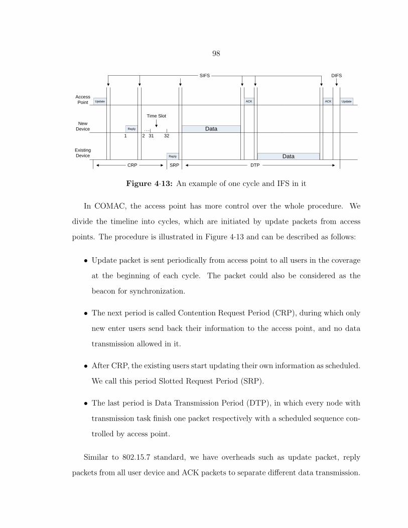
98
Update
Reply
Reply
Data
ACK
Data
ACK
SIFS DIFS
1 2 31 32
Time Slot
Access Point
New Device
Existing Device
Update
CRP SRP DTP
Figure 4·13: An example of one cycle and IFS in it
In COMAC, the access point has more control over the whole procedure. We
divide the timeline into cycles, which are initiated by update packets from access
points. The procedure is illustrated in Figure 4·13 and can be described as follows:
• Update packet is sent periodically from access point to all users in the coverage
at the beginning of each cycle. The packet could also be considered as the
beacon for synchronization.
• The next period is called Contention Request Period (CRP), during which only
new enter users send back their information to the access point, and no data
transmission allowed in it.
• After CRP, the existing users start updating their own information as scheduled.
We call this period Slotted Request Period (SRP).
• The last period is Data Transmission Period (DTP), in which every node with
transmission task finish one packet respectively with a scheduled sequence con-
trolled by access point.
Similar to 802.15.7 standard, we have overheads such as update packet, reply
packets from all user device and ACK packets to separate different data transmission.
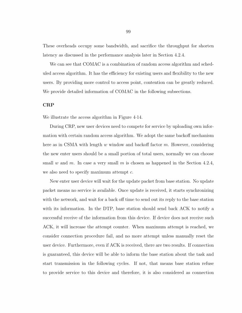
99
These overheads occupy some bandwidth, and sacrifice the throughput for shorten
latency as discussed in the performance analysis later in Section 4.2.4.
We can see that COMAC is a combination of random access algorithm and sched-
uled access algorithm. It has the efficiency for existing users and flexibility to the new
users. By providing more control to access point, contention can be greatly reduced.
We provide detailed information of COMAC in the following subsections.
CRP
We illustrate the access algorithm in Figure 4·14.
During CRP, new user devices need to compete for service by uploading own infor-
mation with certain random access algorithm. We adopt the same backoff mechanism
here as in CSMA with length w window and backoff factor m. However, considering
the new enter users should be a small portion of total users, normally we can choose
small w and m. In case a very small m is chosen as happened in the Section 4.2.4,
we also need to specify maximum attempt c.
New enter user device will wait for the update packet from base station. No update
packet means no service is available. Once update is received, it starts synchronizing
with the network, and wait for a back off time to send out its reply to the base station
with its information. In the DTP, base station should send back ACK to notify a
successful receive of the information from this device. If device does not receive such
ACK, it will increase the attempt counter. When maximum attempt is reached, we
consider connection procedure fail, and no more attempt unless manually reset the
user device. Furthermore, even if ACK is received, there are two results. If connection
is guaranteed, this device will be able to inform the base station about the task and
start transmission in the following cycles. If not, that means base station refuse
to provide service to this device and therefore, it is also considered as connection
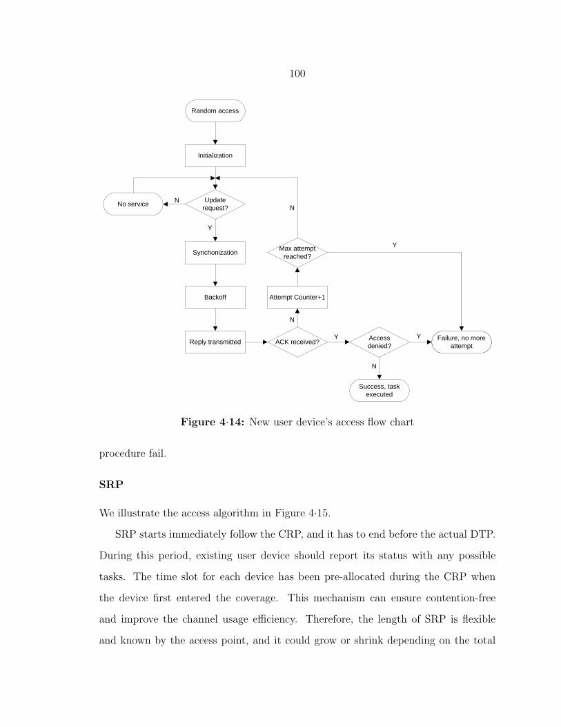
100
Random access
Initialization
Update request?
No service
Synchonization
Backoff
Reply transmitted ACK received?
Max attempt reached?
Failure, no more attempt
Attempt Counter+1
Access denied?
Success, task executed
Y
N
Y Y
Y
N
N
N
Figure 4·14: New user device’s access flow chart
procedure fail.
SRP
We illustrate the access algorithm in Figure 4·15.
SRP starts immediately follow the CRP, and it has to end before the actual DTP.
During this period, existing user device should report its status with any possible
tasks. The time slot for each device has been pre-allocated during the CRP when
the device first entered the coverage. This mechanism can ensure contention-free
and improve the channel usage efficiency. Therefore, the length of SRP is flexible
and known by the access point, and it could grow or shrink depending on the total

101
amount of user devices.
Slotted access
Update request?
No service
Synchonization
Y
N
Wait for SRP
Wait for own slot Task?
N
Disassociate?
Service Stop
Y
Reply transmitted Reply transmitted ACK received?
Access denied?
Reply transmitted
Data transmission
N
N
Y
Y
Y
N
Figure 4·15: Existing user device’s access flow chart
Existing user device will also wait for the update packet from base station. No
update packet means no service is available. Once update is received, it starts synchro-
nizing with the network and wait for its own slot in the SRP. If it has no transmission
request in current cycle, it will only reply back to base station to update its own
information. Otherwise, if it wants to disconnect from the service, it will reply the
disassociation request. In the third case, if it has a transmission task, it will send back
the reply with the transmission request. Similarly, in the DTP, base station should
send back ACK to notify a successful receive of the information from this device. If
device does not receive such ACK, the device waits for the next cycle. When ACK
is successfully received, if access is denied, the device will disconnect and wait for
manually reset, otherwise, transmission will be established as requested.
102
DTP
After SRP, access point will collect information from all replies. It then schedules a
transmission task sequence in current cycle, and all tasks will be executed in DTP
based on this sequence.
The access point uses ACK contained with command information as guard to
separate different user’s task and also invoke next user’s transmission. The packet
length in each task transmission is pre-defined and it can affect the channel efficiency
as well as latency performance as indicated in Section 4.2.4.
Inter-frame Spacing (IFS)
The MAC sublayer needs a finite amount of time to process data received by the
physical layer. To allow for this, two successive frames transmitted from a device
shall be separated by at least an IFS period.
In CSMA, there are two types of IFS, DIFS and SIFS. SIFS is shorter than DIFS,
and it follows after RTS, CTS and data packet. DIFS, also the length for channel
sensing, is only applied after ACK when channel sensing could occur. Since SIFS is
much shorter than DIFS, any nodes not notified by RTS and CTS could still avoid
collision by channel sensing.
The IFS and other access mechanisms can also be illustrated in Figure 4·13.
Differences from IEEE 802.15.7 Standard
Both COMAC and MAC of 802.15.7 Standard solving the contention by restrain-
ing the random access in a specified period and synchronizing all periods by either
update request or beacon. Both schemes provide two methods for accessing the chan-
nels. Both schemes provide flexibility on length of each period within the cycle or
superframe. However, some differences make them perform differently and suitable

103
for different applications.
1. In COMAC, the cycle length is not fixed. It depends on how many transmission
requests from user devices. In this way, by being acknowledged from user devices
in each cycle, COMAC can remove idle states, which therefore increases the
throughput.
2. In COAMC, only a short reply packet, without data packet, is needed from
user device in CRP. Since new enter user device can only access the channel in
CRP, this suggests that the base station is able to accept more new enter user
devices, so that the average latency for them will be shorten.
3. In COMAC, the base station will track the status of all user devices under its
coverage. The additional reply and control packets will occupy some bandwidth,
but on the other hand, can benefit applications required high security.
The Section 4.2.4 will discuss the differences in performance in terms of latency
and throughput under different scenarios.
4.2.4 Performance Analysis of MAC Schemes
In this section, we compare the performance among three MAC schemes, COMAC,
MAC specification of 802.15.7 standard and original CSMA/CA. Although CSMA/CA
is not suitable for our VLC system due to the increased interference, it has been
adopted for several wireless standards and therefore can give us performance results
over multiple existing wireless techniques. We adopt the same set of parameters
defined in Section 4.1.3.
In wireless communication and network, latency and throughput are two impor-
tant parameters for evaluation. We start with latency analysis of new enter user
device.

104
Latency Comparison
We adopt the same set of parameters defined in Section 4.1.3 for 802.15.7 standard
and CSMA/CA. For fairness, the specifications of COMAC are set to be the same
as indicated in Table 4.6. For random access mechanism, we consider W = 32 and
m = 0. We also set the number of existing users N = 20. This means no matter how
many new enter user devices accepted in current superframe or cycle, we consider the
same number of user devices will leave the coverage, so that the total amount of data
packets transmitted in each superframe or cycle are the same for comparison.
Furthermore, latency problem aggravates with the number of user devices com-
peting for the channel. Therefore, we consider the worst scenario for latency, fully
loaded network, where every user device always has a transmission request. Since
we consider the same scenario as in Section 4.1.3, (4.1) and (4.2) still hold here and
give us a unique pair of results for packet transmission probability, τ , and conditional
collision probability, p.
Table 4.6: Time variables definition of COMAC [Bia00]Payload size 8184 bitsMAC header 272 bitsPHY header 128 bits
ACK 112 bits + PHY headerUpdate 160 bits + PHY headerReply 112 bits + PHY header
Propagation delay (δ) 1 µsSlot time (σ) 50 µs
SIFS 28 µsDIFS 128 µs
For any new enter user device, there are two results for each connection attempt,
not accepted and accepted. For each attempt with CSMA/CA, we define Ta as the
waiting time if user device is accepted, and Tb as the waiting time if not accepted.
Similarly, we also define Th and Tm for COMAC and 802.15.7 standard if accepted,
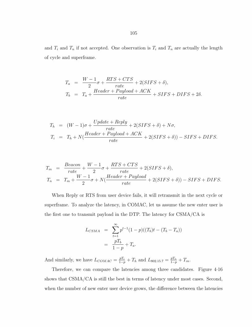
105
and Ti and Tn if not accepted. One observation is Ti and Tn are actually the length
of cycle and superframe.
Ta =W − 1
2σ +
RTS + CTS
rate+ 2(SIFS + δ),
Tb = Ta +Header + Payload+ ACK
rate+ SIFS +DIFS + 2δ.
Th = (W − 1)σ +Update+Reply
rate+ 2(SIFS + δ) +Nσ,
Ti = Th +N(Header + Payload+ ACK
rate+ 2(SIFS + δ))− SIFS +DIFS.
Tm =Beacon
rate+
W − 1
2σ +
RTS + CTS
rate+ 2(SIFS + δ),
Tn = Tm +W − 1
2σ +N(
Header + Payload
rate+ 2(SIFS + δ))− SIFS +DIFS.
When Reply or RTS from user device fails, it will retransmit in the next cycle or
superframe. To analyze the latency, in COMAC, let us assume the new enter user is
the first one to transmit payload in the DTP. The latency for CSMA/CA is
LCSMA =∞∑t=1
pt−1(1− p)((Tb)t− (Tb − Ta))
=pTb
1− p+ Ta.
And similarly, we have LCOMAC = pTi
1−p+ Th and L802.15.7 =
pTn
1−p+ Tm.
Therefore, we can compare the latencies among three candidates. Figure 4·16
shows that CSMA/CA is still the best in terms of latency under most cases. Second,
when the number of new enter user device grows, the difference between the latencies
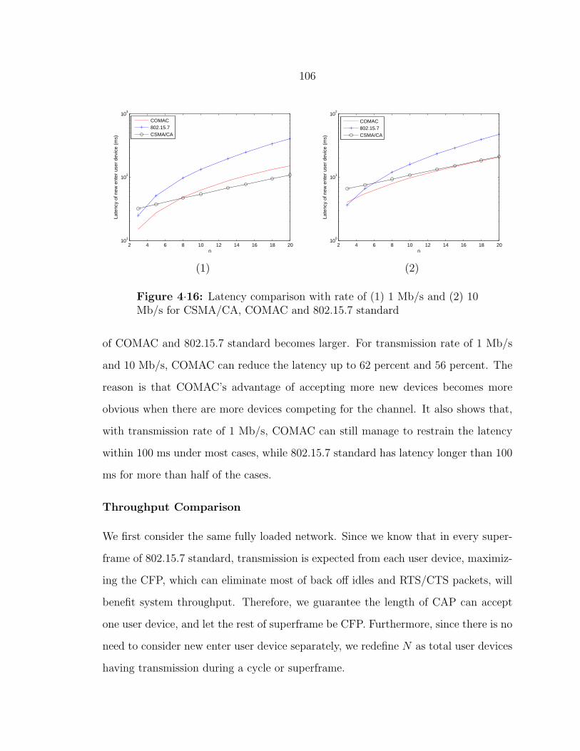
106
2 4 6 8 10 12 14 16 18 2010
1
102
103
n
Late
ncy
of n
ew e
nter
use
r de
vice
(m
s)
COMAC802.15.7CSMA/CA
(1)
2 4 6 8 10 12 14 16 18 2010
0
101
102
n
Late
ncy
of n
ew e
nter
use
r de
vice
(m
s)
COMAC802.15.7CSMA/CA
(2)
Figure 4·16: Latency comparison with rate of (1) 1 Mb/s and (2) 10Mb/s for CSMA/CA, COMAC and 802.15.7 standard
of COMAC and 802.15.7 standard becomes larger. For transmission rate of 1 Mb/s
and 10 Mb/s, COMAC can reduce the latency up to 62 percent and 56 percent. The
reason is that COMAC’s advantage of accepting more new devices becomes more
obvious when there are more devices competing for the channel. It also shows that,
with transmission rate of 1 Mb/s, COMAC can still manage to restrain the latency
within 100 ms under most cases, while 802.15.7 standard has latency longer than 100
ms for more than half of the cases.
Throughput Comparison
We first consider the same fully loaded network. Since we know that in every super-
frame of 802.15.7 standard, transmission is expected from each user device, maximiz-
ing the CFP, which can eliminate most of back off idles and RTS/CTS packets, will
benefit system throughput. Therefore, we guarantee the length of CAP can accept
one user device, and let the rest of superframe be CFP. Furthermore, since there is no
need to consider new enter user device separately, we redefine N as total user devices
having transmission during a cycle or superframe.

107
The normalized system throughput (ratio of transmission for data packets) of
CSMA/CA has been discussed in Section 4.1.3 and given as (4.3). However, different
from this statistical result, the throughputs of COMAC and 802.15.7 standard are
more deterministic mainly due to the fact that a large portion of the cycle works as
a scheduled MAC. The normalized system throughputs are defined as
Scomac =Header+Payload
rateN
Ti
, (4.4)
S802.15.7 =Header+Payload
rateN
Tn
. (4.5)
2 4 6 8 10 12 14 16 18 200.5
0.55
0.6
0.65
0.7
0.75
0.8
0.85
0.9
0.95
1
N
Nor
mal
ized
sys
tem
thro
ughp
ut
COMAC802.15.7CSMA/CA
(1)
2 4 6 8 10 12 14 16 18 200.5
0.55
0.6
0.65
0.7
0.75
0.8
0.85
0.9
0.95
1
N
Nor
mal
ized
sys
tem
thro
ughp
ut
COMAC802.15.7CSMA/CA
(2)
Figure 4·17: Normalized throughput with rate of (1) 1 Mb/s and (2)10 Mb/s for CSMA/CA, COMAC and 802.15.7 standard (fully loadednetwork)
Figure 4·17 illustrates the normalized system throughput based on (4.3), (4.5) and
(4.5). Both COMAC and 802.15.7 standard perform better in terms of throughput
than CSMA/CA. This is because by having SRP and CFP, both are closer to be
scheduling MAC scheme. However, in order to reduce latency, COMAC sacrifices up
to 6 percent of bandwidth on additional control overheads.
The second scenario we consider is partial loaded network. In other words, user
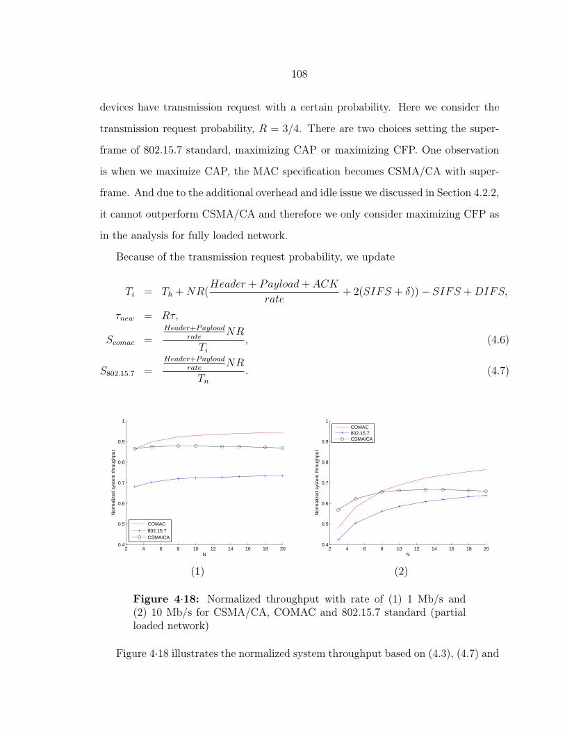
108
devices have transmission request with a certain probability. Here we consider the
transmission request probability, R = 3/4. There are two choices setting the super-
frame of 802.15.7 standard, maximizing CAP or maximizing CFP. One observation
is when we maximize CAP, the MAC specification becomes CSMA/CA with super-
frame. And due to the additional overhead and idle issue we discussed in Section 4.2.2,
it cannot outperform CSMA/CA and therefore we only consider maximizing CFP as
in the analysis for fully loaded network.
Because of the transmission request probability, we update
Ti = Th +NR(Header + Payload+ ACK
rate+ 2(SIFS + δ))− SIFS +DIFS,
τnew = Rτ,
Scomac =Header+Payload
rateNR
Ti
, (4.6)
S802.15.7 =Header+Payload
rateNR
Tn
. (4.7)
2 4 6 8 10 12 14 16 18 200.4
0.5
0.6
0.7
0.8
0.9
1
N
Nor
mal
ized
sys
tem
thro
ughp
ut
COMAC802.15.7CSMA/CA
(1)
2 4 6 8 10 12 14 16 18 200.4
0.5
0.6
0.7
0.8
0.9
1
N
Nor
mal
ized
sys
tem
thro
ughp
ut
COMAC802.15.7CSMA/CA
(2)
Figure 4·18: Normalized throughput with rate of (1) 1 Mb/s and(2) 10 Mb/s for CSMA/CA, COMAC and 802.15.7 standard (partialloaded network)
Figure 4·18 illustrates the normalized system throughput based on (4.3), (4.7) and
109
(4.7). Different from Figure 4·17, we see that COMAC outperforms 802.15.7 standard
due to the fact that in the partial loaded network there could be empty GTS that
can compromise the system throughput. And such difference is larger for lower data
rate.
Conclusion on COMAC
From previous subsections, because COMAC only requires short reply packet in CRP,
base station is able to accept more new enter user device. The analysis shows a great
reduction of latency comparing to 802.15.7 standard. Regarding to system through-
put, 802.15.7 standard slightly beats COMAC in fully loaded network, while COMAC
outperforms 802.15.7 standard when user devices don’t always have transmission re-
quests.
As a conclusion, combining with the characteristic of keeping each device’s status
in every cycle, COMAC is good candidate for applications requiring short latency
and high security.
4.3 Summary
In this chapter, we present our work on providing a novel multi-hop multi-access VLC
solution. Two challenges have been addressed regarding to blocking of service and
multiple access contention.
In the first part, we introduce two networking protocols for the LOS problem.
From the discussion in previous section, we know that both protocols have advantages
and disadvantages. The peer-to-peer protocol leverages a narrow beam and FOV
from the proposed device and thereby can have good performance in terms of speed
without a central host. The peer-to-host protocol, in contrast, is simpler and easy
to implement, but due to the diffuse link model and interference, is less amenable to

110
high data rates and requires a host to be available.
The adoption of each protocol depends on the desired behavior of the communica-
tion model. When the application requires transferring large data, the first protocol
is most appropriate. Furthermore, for most of outdoor cases, there is no support from
a host that you cannot form a two-layer architecture. So, the first protocol is the only
choice. If the application produces short bursts of data or the data rate requirements
are relaxed as in many industrial automation scenarios, then the second protocol is a
good choice. It is simpler and can readily support mobility of devices. Applications
like in-office P2P messaging, in-building location services and the like can use the
second protocol.
The second part proposes a novel MAC scheme, called COMAC. VLC systems
with multiple mobile users and large coverage need to find a low complexity low cost
MAC scheme to solve the challenges like directional signal, high signal attenuation
and limited coverage. 802.15.7 standard provides one solution. We propose another
solution called COMAC which can shorten the latency by more than 50 percent with
about 6 % sacrifice on throughput in fully loaded network comparing to 802.15.7
standard. Furthermore, when user devices do not always have transmission, COMAC
will have an improved throughput and even outperform 802.15.7 standard.
Together, we demonstrate that with this novel set of protocols and scheme at
networking layer, VLC can overcome two unique and critical challenges without much
additional cost. And this work can actually fill an empty research gap of VLC and
eventually help any indoor VLC prototypes advance to a much more reliable and
practical system providing wireless communication service.
111
Chapter 5
Conclusion
5.1 Summary
VLC has become a popular research topic in recent years due to the advantages of
reduced cost and complexity by combining with illumination, free and higher band-
width and better security. However, as every frontier technology, it also comes with
challenges and problems. In this dissertation, we conduct further researches on mod-
eling the indoor VLC system and analysis on DMT modulation, followed by a novel
multi-hop multi-access solution to provide a robust and practical communication sys-
tem. The significant contributions in this dissertation are summarized below:
1. Indoor VLC Model and DMT Analysis
In Section 3.2, we provide tools to model the indoor scenarios for VLC. By
adjusting the parameters of devices, room size, light source location and so on,
we are able to predict the certain link performance of indoor VLC systems, such
as signal attenuation, BER, rate upper bound and SNR.
In Section 3.3, we present performance analysis on BER and channel capacity.
The results show that DMT alone isn’t suitable for scenarios with high noise or
interference and can outperform OOK only when SNR is high. However, the
novel analysis on channel capacity further shows it has much greater potential
to reach the maximum based on information theory. OOK can only reach 1
b/s/Hz while DMT can achieve more than 5 b/s/Hz with SNR higher than 40

112
dB.
2. Networking Protocols
One of the most important characteristics of VLC is signal occlusion of the
LOS channels. In Section 4.1.2, we propose two networking protocols to solve
the problem by relaying the signal with different strategies. The adoption of
each protocol depends on the desired behavior of the communication model.
A hexagonal cylinder shape device design is also presented to collaborate with
two protocols with comprehensive throughput analysis. Simulations result show
that in a 4 user case, considering the rate capacities of devices for uplink and
node-to-node transmission to be 2 Mb/s and 10 Mb/s respectively, each user
can have an average rate of 422 kb/s for uploading and a total rate over 9 Mb/s
giving the transmission on every face of the device a minimum rate in excess of
1.5 Mb/s.
3. Centralized Optical MAC
For any indoor wireless applications, low complexity and cost are always one of
the most important characteristics needed to be addressed. However, due to the
directional signal and limited coverage provided from each light indoor, a VLC
MAC scheme which can solve the additional contention is required, especially
when mobility is also taken into consideration.
Our proposed COMAC scheme provides an alternative solution that can solve
the collision, and from the discussion in Section 4.2.4, it can shorten the la-
tency by more than 50 percent with about 6 percent sacrifice on throughput in
fully loaded network comparing to 802.15.7 standard. Furthermore, when user
devices do not always have transmission, it will have an improved throughput
and even outperform 802.15.7 standard. The different characteristics make it a

113
good choice for applications requiring short latency and high security.
5.2 Future Work
VLC is a new and large research area needs to be explored. There are still lots of
open challenges. We list several of them which are related to or can be considered as
an extension of the works in this dissertation.
1. DMT-OCDMA
CDMA is a much more complex scheme which handles the channel access from
the aspect of signaling. As mentioned in Section 2.1.6, the research of it in
FSO is quite different from RF due to the optical signal characteristics. The
challenge is CDMA is overqualified and too complex for most of indoor appli-
cations. However, it is still reasonable to believe that with the development of
semiconductor, it will become popular for small wireless scenarios in the future.
Integrated with DMT, we can therefore have a powerful signaling solution for
VLC.
2. Extension on MIMO
During the discussion in Section 4.1.1, we know that the user device is comprised
by several independent faces which can be considered as narrow directional and
narrow FOV MIMO transceiver. So, the severe multipath distortion and signal
attenuation problems in diffuse link may not be a big concern in the desktop
level communication among different user devices. Furthermore, as we all know,
the wavelength of optical signal is much smaller which makes each face of the
user device into an essential MIMO transceivers. The development of MIMO in
our design doesn’t need any additional geometry requirements like MSD does.
Therefore, exploring MIMO feature on the device can be a good extension of

114
our research.
3. Implementation Issues
The researches conducted in this dissertation are theoretical. Therefore, im-
plementation work will be one of the future works. COMAC, which does not
require any additional support from device design, can be the one to start with.
The implementation of COMAC includes several different modules as illustrated
in Figure 5·1. Some modules are considered as additional features, and marked
in black in the figure.
Control EngineTask Engine
Interface Engine
Packet Engine
Node Management
Resource Allocation
Comm. Medium
Figure 5·1: Software structure diagram
Furthermore, when the user device described in Section 4.1.1 or similar func-
tionality becomes available, the implementation of networking protocols in Sec-
tion 4.1.2 can be another future work. Integration with other techniques such
as channel coding and modulation is also another important direction needed
to be addressed.

References
[AH95] M. Abtahi and H. Hashemi. Simulation of Indoor Propagation Channel at InfraredFrequencies in Furnished Office Environment. In 6th IEEE International Sympo-sium on Personal, Indoor and Mobile Radio Communications, volume 1, pages306–310, September 1995.
[AK03] Y. Alqudah and M. Kavehrad. MIMO Characterization of Indoor Wireless Op-tical Link Using a Diffuse-Transmission Configuration. IEEE Transactions onCommunications, 51(9):1554–1560, September 2003.
[AK06] P. Amirshahi and M. Kavehrad. Broadband Access Over Medium and Low VoltagePower-Lines and Use of White Light Emitting Diodes for Indoor Communications.In 3rd IEEE Consumer Communications and Networking Conference, volume 2,pages 897–901, January 2006.
[AKJ04] Y. Alqudah, M. Kavehrad, and S. Jivkova. Optical Wireless Multi-Spot Diffusing;a MIMO Configuration. In IEEE International Conference on Communications,volume 6, pages 3348–3352, June 2004.
[AL06] J. Armstrong and A. J. Lowery. Power Efficient Optical OFDM. ElectronicsLetters, 42(6):370–372, March 2006.
[Arn03] S. Arnon. Optical Wireless Communication. In R. G. Driggers, editor, Encyclope-dia of Optical Engineering, volume 2, pages 1866–1886. Marcel Dekker, September2003.
[Ass97] Infrared Data Association. Infrared Data Association Serial Infrared PhysicalLayer Link Specification, Version 1.2. Technical report, November 1997. http:
//web.media.mit.edu/~ayb/irx/irda/IrPHY_1_2.PDF.
[ASWH09] S. An, Y. Son, Y. Won, and S. Han. Visible LED Wireless Optical Trans-mission in Optical Access Network using Electroabsorption Transceiver. In AsiaCommunications and Photonics Conference and Exhibition, November 2009.
[ATO10] A. H. Azhar, T.-A. Tran, and D. C. O’Brien. Demonstration of High-SpeedData Transmission Using MIMO-OFDM Visible Light Communications. In IEEEGLOBECOM Workshops, pages 1052–1056, December 2010.
115
116
[Bia00] G. Bianchi. Performance Analysis of the IEEE 802.11 Distributed CoordinationFunction. IEEE Journal on Selected Areas in Communications, 18(3):535–547,March 2000.
[BKK+93] J. R. Barry, J. M. Kahn, W. J. Krause, E. A. Lee, and D. G. Messerschmitt.Simulation of Multipath Impulse Response for Indoor Wireless Optical Channels.IEEE Journal on Selected Areas in Communications, 11(3):367–379, April 1993.
[Bou05] A. C. Boucouvalas. Challenges in Optical Wireless Communications. Optics &Photonics News, 16(9):36–39, 2005.
[BPW+10] O. Bouchet, P. Porcon, M. Wolf, L. Grobe, J. W. Walewski, S. Nerreter, K.-D. Langer, L. Fernandez, J. Vucic, T. Kamalakis, G. Ntogari, and E. Gueutier.Visible-Light Communication System Enabling 73 Mb/s Data Streaming. In IEEEGLOBECOM Workshops, pages 1042–1046, December 2010.
[BSWG99] J. Bellon, M. J. N. Sibley, D. R. Wisley, and S. D. Greaves. Hub Architecturefor Infrared Wireless Networks in Office Environments. IEE Proceedings Optoelec-tronics, 146(2):78–82, August 1999.
[BYT] BYTELIGHT. www.bytelight.net.
[Car03] J. B. Carruthers. Wireless Infrared Communications. In J. G. Proakis, editor,Wiley Encyclopedia of Telecommunications, volume 5, pages 2925–2931. Wiley-Interscience, January 2003.
[CCXR10] K. Cui, G. Chen, Z. Xu, and R. D. Roberts. Line-of-Sight Visible Light Com-munication System Design and Demonstration. In 7th International Symposium onCommunication Systems Networks and Digital Signal Processing, pages 621–625,July 2010.
[CK96] J. B. Carruthers and J. M. Kahn. Multiple-Subcarrier Modulation for NondirectedWireless Indoor Infrared Communication. IEEE Journal on Selected Areas inCommunications, 14(3):538–546, April 1996.
[CK97] J. B. Carruthers and J. M. Kahn. Modeling of Nondirected Wireless InfraredChannels. IEEE Transactions on Communications, 45(10):1260–1268, October1997.
[CML10] J. Chau, K. Matarese, and T. D.C. Little. IP-Enabled LED Lighting Support-ing Indoor Mobile and Wireless Communications. In 8th Annual InternationalConference on Mobile Systems, Applications and Services, June 2010. Poster andDemonstration Session Program.
[Com93] Commission Electrotechnique Internationale/International Electrotechnical Com-mission. CEI/IEC 825-1: Safety of Laser Products. Technical report, 1993.
117
[Con09] Visible-Light Communication Consortium. Visible Light Communication PhysicalLayer Specification, Version 1.1. Technical report, August 2009.
[CSW89] F. R. K. Chung, J. A. Salehi, and V. K. Wei. Optical Orthogonal Codes: Design,Analysis, and Applications. IEEE Transactions on Information Theory, 35(3):595–604, May 1989.
[CYRV02] R. R. Choudhury, X. Yang, R. Ramanathan, and N. H. Vaidya. Using Di-rectional Antennas for Medium Access Control in Ad Hoc Networks. In 8th An-nual International Conference on Mobile Computing and Networking, pages 59–70,September 2002.
[Dif] Infra-Com. www.infra-com.com.
[Dou04] T. Douseki. A Batteryless Optical-Wireless System withWhite-LED Illumination.In 15th IEEE International Symposium on Personal, Indoor and Mobile RadioCommunications, volume 4, pages 2529–2533, September 2004.
[FK03] K. Fazel and S. Kasier. Multi-Carrier and Spread Spectrum Systems. Wiley,November 2003.
[GLL+07] J. Grubor, K.-D. Langer, S. C. J. Lee, T. Koonen, and J. W. Walewski. Wire-less High-Speed Data Transmission with Phosphorescent White-Light LEDs. In33rd European Conference and Exhibition of Optical Communication, pages 1–2,September 2007.
[GPJR+05] O. Gonzalez, R. Perez-Jimenez, S. Rodriguez, J. Rabadan, and A. Ayala.OFDM Over Indoor Wireless Optical Channel. IEE Proceedings - Optoelectronics,152(4):199–204, August 2005.
[GRLW08a] J. Grubor, S. Randel, K.-D. Langer, and J. W. Walewski. Bandwidth-EfficientIndoor Optical Wireless Communications with White Light-Emitting Diodes. In6th International Symposium on Communication Systems, Networks and DigitalSignal Processing, pages 165–169, July 2008.
[GRLW08b] J. Grubor, S. Randel, K.-D. Langer, and J. W. Walewski. Broadband Infor-mation Broadcasting Using LED-Based Interior Lighting. Journal of LightwaveTechnology, 26(24):3883–3892, December 2008.
[Har08] S. Haruyama. Japan’s Visible Light Communications Consortium and Its Stan-dardization Activities. mentor.ieee.org/802.15/dcn/08/15-08-0061-00-0
vlc-japan-s-visible-light-communications-consortium-and-its.pdf, 2008.
[HK06] S. Hranilovic and F. R. Kschischang. A Pixelated MIMO Wireless Optical Com-munication System. IEEE Journal of Selected Topics in Quantum Electronics,12(4):859–874, July/August 2006.

118
[Hos11] T. Hosking. Free Space Optics (Optical Wireless) Global Market Forecast andAnalysis. Technical report, ElectroniCast Consultants, May 2011. electronic
astconsultants.com/files/FSO_NEWS_RELEASE.May.2011.ElectroniCast.doc.
[Hra04] S. Hrarilovic. Wireless Optical Communication System. Springer, September2004.
[HYK+94] H. Hashemi, G. Yun, M. Kavehrad, F. Behbahani, and P. Galko. Indoor Prop-agation Measurements at Infrared Frequencies for Wireless Local Area NetworksApplications. IEEE Transactions on Vehicular Technology, 43(3):562–576, August1994.
[Inf] Infrared Communication Devices. www.mobilecomms-technology.com/projects
/irda/irda1.html.
[Ins93] American National Standards Institute. American National Standard for Safe Useof Lasers (Ansi Z136.1-1993). Technical report, June 1993.
[IPE+08] S. Iwasaki, C. Premachandra, T. Endo, T. Fujii, M. Tanimoto, and Y. Kimura.Visible Light Road-to-Vehicle Communication Using High-Speed Camera. In IEEEIntelligent Vehicles Symposium, pages 13–18, June 2008.
[JHK04] S. Jivkova, B. A. Hristov, and M. Kavehrad. Power-Efficient Multi-Spot-DiffuseMulti-Input-Multi-Output Approach to Broad-Band Optical Wireless Communi-cations. IEEE Transactions on Vehicular Technology, 53(3):882–889, May 2004.
[JVC] JVC. www.jvc-victor.co.jp.
[Kav07] M. Kavehrad. Broadband Room Service by Light. Scientific American, pages82–87, July 2007.
[KB97] J. M. Kahn and J. R. Barry. Wireless Infrared Communications. Proceedings ofthe IEEE, 85(2):265–298, 1997.
[KHNS07] H. Kotake, S. Haruyama, M. Nakagawa, and K. Seki. BER Characteristic ofGround-to-Train Communication System Using Free-Space Optics Technology. In9th International Conference on Transparent Optical Networks, volume 3, pages165–169, July 2007.
[KJT03] T. Korakis, G. Jakllari, and L. Tassiulas. A MAC Protocol for Full Exploitationof Directional Antennas in Ad-Hoc Wireless Networks. In 4th ACM InternationalSymposium on Mobile Ad Hoc Networking and Computing, pages 98–107, June2003.

119
[KKC95] J. M. Kahn, W. J. Krause, and J. B. Carruthers. Experimental Characterizationof Non-Directed Indoor Infrared Channels. IEEE Transactions on Communica-tions, 234(43):1613–1623, February/March/April 1995.
[KOG70] S. Karp, E. L. O’Neill, and R. M. Gagliardi. Communication Theory for theFree-Space Optical Channel. Proceedings of the IEEE, 58(10):1611–1626, October1970.
[KS01] A. Keshavarzian and J. A. Salehi. Synchronization of Optical Orthogonal Codesin Optical CDMA Systems via Simple Serial-Search Method. In IEEE GlobalTelecommunications Conference, volume 3, pages 1460–1464, November 2001.
[KSV00] Y.-B. Ko, V. Shankarkumar, and N. H. Vaidya. Medium Access Control Pro-tocols Using Directional Antennas in Ad Hoc Networks. In Proceedings. IEEEINFOCOM, volume 1, pages 13–21, March 2000.
[LDS+08] T. D.C. Little, P. Dib, K. Shah, N. Barraford, and B. Gallagher. UsingLED Lighting for Ubiquitous Indoor Wireless Networking. In IEEE InternationalConference on Wireless and Mobile Computing, Networking and Communications,pages 373–378, October 2008.
[LED] LUXEON Rebel General Purpose White Portfolio. www.philipslumileds.com/
pdfs/DS64.pdf.
[LGB+08] K.-D. Langer, J. Grubor, O. Bouchet, M. El Tabach, J. W. Walewski, S. Randel,M. Franke, S. Nerreter, D. C. O’Brien, G. E. Faulkner, I. Neokosmidis, G. Ntogari,and M. Wolf. Optical Wireless Communications for Broadband Access in HomeArea Networks. In 10th Anniversary International Conference on TransparentOptical Networks, volume 4, pages 149–154, June 2008.
[LIH09] X. Lin, K. Ikawa, and K. Hirohashi. High-Speed Full-Duplex Multiaccess Systemfor LED-Based Wireless Communications Using Visible Light. In InternationalSymposium on Optical Engineering and Photonic Technology, July 2009.
[LMKM08] X. Liu, H. Makino, S. Kobayashi, and Y. Maeda. Research of Practical IndoorGuidance Platform Using Fluorescent Light Communication. IEICE Transactionson Communications, E91.B(11):3507–3515, November 2008.
[LVX] LVX System. www.lvx-system.com.
[Mat09] T. Matsumura. Channel Models in VLCC. https://mentor.ieee.org/802.15
/dcn/09/15-09-0065-01-0007-channel-models-in-vlcc.pdf, January 2009.
[MHK08] Y. Matsumoto, T. Hara, and Y. Kimura. CMOS Photo-Transistor Array Detec-tion System for Visual Light Identification (ID). In 5th International Conferenceon Networked Sensing Systems, pages 99–102, June 2008.

120
[MK96] G. W. Marsh and J. M. Kahn. Performance Evaluation of Experimental 50-Mb/s Diffuse Infrared Wireless Link Using On-Off Keying with Decision-FeedbackEqualization. IEEE Transactions on Communications, 44(11):1496–1504, Novem-ber 1996.
[MN99] T. Mukai and S. Nakamura. White and UV LEDs. Oyo Buturi, 68(2):152–155,1999.
[MOF+08a] H. Le Minh, D. C. O’Brien, G. E. Faulkner, L. Zeng, K. Lee, D. Jung, andY. Oh. 80 Mbit/s Visible Light Communications Using Pre-Equalized White LED.In 34th European Conference on Optical Communication, pages 1–2, September2008.
[MOF+08b] H. Le Minh, D. C. O’Brien, G. E. Faulkner, L. Zeng, K. Lee, D. Jung, andY. Oh. High-Speed Visible Light Communications Using Multiple-Resonant Equal-ization. IEEE Photonics Technology Letters, 20(14):1243–1245, July 2008.
[MOF+09] H. Le Minh, D. C. O’Brien, G. E. Faulkner, L. Zeng, K. Lee, D. Jung, Y. Oh, andE. T. Won. 100-Mb/s NRZ Visible Light Communications Using a PostequalizedWhite LED. IEEE Photonics Technology Letters, 21(15):1063–1065, August 2009.
[MOF10] H. Le Minh, D. C. O’Brien, and G. E. Faulkner. A Gigabit/s Indoor OpticalWireless System for Home Access Networks. In 7th International Symposium onCommunication Systems Networks and Digital Signal Processing, pages 532–536,July 2010.
[Nav] Nautical Marconi Spotlight Navy Signal Lamp Floor Light. http://cgi.ebay.c
om/Nautical-Marconi-Spotlight-Navy-Signal-Lamp-Floor-Light-/30044709
4900.
[NUL04] S. M. Navidpour, M. Uysal, and J. Li. BER Performance of MIMO Free-SpaceOptical Links. In IEEE 60th Vehicular Technology Conference, volume 5, pages3378–3382, September 2004.
[NYYH00] A. Nasipuri, S. Ye, J. You, and R. E. Hiromoto. A MAC Protocol for MobileAd Hoc Networks Using Directional Antennas. In IEEE Wireless Communicationsand Networking Conference, volume 3, pages 1214–1219, September 2000.
[oEG07] Institute of Electrical and Electronics Engineers WG802.11-Wireless Local AreaNetworks (WLAN)Working Group. Wi-Fi CERTIFIED 802.11n draft 2.0: Longer-Range, Faster-Throughput Multimedia-Grade Wi-Fi®Networks. Technical re-port, June 2007. http://www.wi-fi.org/files/kc/WFA_802_11n_Industry_
June07.pdf.
121
[oEG11] Institute of Electrical and Electronics Engineers WG802.15-Wireless PersonalArea Network (WPAN) Working Group. Standard for Short-Range Wireless Op-tical Communication Using Visible Light. Technical report, April 2011. http:
//ieeexplore.ieee.org/stamp/stamp.jsp?tp=&arnumber=5764866.
[OFJ+06] D. C. O’Brien, G. E. Faulkner, K. Jim, D. J. Edwards, E. B. Zyambo, P. Stavri-nou, G. Parry, J. Bellon, M. J. Sibley, R. J. Samsudin, D. M. Holburn, V. A.Lalithambika, V. M. Joyner, and R. J. Mears. Experimental Characterizationof Integrated Optical Wireless Components. IEEE Photonics Technology Letters,18(8):977–979, April 2006.
[OME] OMEGA Project. www.ict-omega.eu.
[OYY+09] S. Okada, T. Yendo, T. Yamazato, T. Fujii, M. Tanimoto, and Y. Kimura.On-Vehicle Receiver for Distant Visible Light Road-to-Vehicle Communication. InIEEE Intelligent Vehicles Symposium, pages 1033–1038, June 2009.
[PG09] J. M. Palmer and B. G. Grant. The Art of Radiometry. SPIE Press, December2009.
[PHI] LUXEON Rebel White LEDs. www.philipslumileds.com/products/luxeon-r
ebel/luxeon-rebel-white.
[Pho] Silicon PIN Photodiode with Very Short Switching Time, SFH 213/SFH 213 FA.http://rocky.digikey.com/WebLib/Osram/WebData/sfh213fa.pdf.
[PKLC02] G. Pang, T. Kwan, H. Liu, and C. Chan. LED Wireless. IEEE IndustryApplications Magazine, 8(1):21–28, January/February 2002.
[PL09] G. B. Prince and T. D. C. Little. On the Performance Gains of CooperativeTransmit Beamforming Applied to Intensity Modulated Direct Detection VisibleLight Communication Networks. Master’s thesis, Boston University, 2009.
[Pla] Plaintree Systems. www.plaintree.com.
[Pto] Optical SETI Program. http://seti.ucolick.org/optical/.
[Qaz06] S. Qazi. Challenges In Outdoor and Indoor Optical Wireless Communications.In International Conference on Wireless Networks, pages 448–458, June 2006.
[RGR10] R. Roberts, P. Gopalakrishnan, and S. Rathi. Visible Light Positioning: Auto-motive Use Case. In IEEE Vehicular Networking Conference, December 2010.
[Ros] Iulian Rosu. Understanding Noise Figure. Technical report, Amateur Radio Com-munity. www.qsl.net/va3iul/Noise/noise.html.

122
[RX09] R. Roberts and Z. Xu. Update on VLC Link Budget Work. https://mentor.i
eee.org/802.15/dcn/09/15-09-0635-01-0007-update-on-vlc-link-budget-w
ork.ppt, September 2009.
[Sch06] E. F. Schubert. Light-Emitting Diodes. Cambridge University Press, June 2006.
[SHJ05] A. R. Shah, R. C.J. Hsu, and B. Jalali. ISI Equalization for a Coherent OpticalMIMO (COMIMO) System. In Conference on Lasers and Electro-Optics, volume 2,pages 1348–1350, May 2005.
[SHN08] T. Saito, S. Haruyama, and M. Nakagawa. A New Tracking Method Using ImageSensor and Photo Diode for Visible Light Road-to-Vehicle Communication. In10th International Conference on Advanced Communication Technology, volume 1,pages 673–678, February 2008.
[Smi98] M. T. Smith. Smart Cards: Integrating for Portable Complexity. Computer,31(8):110–115, August 1998.
[Smo] Smoke Signal Cartoon. www.cartoonstock.com/newscartoons/directory/s/
smoke_signal.asp.
[SSV+10] N. Shrestha, M. Sohail, C. Viphavakit, P. Saengudomlert, and W. S. Mohammed.Demonstration of Visible Light Communications Using RGB LEDs in an IndoorEnvironment. In International Conference on Electrical Engineering/ElectronicsComputer Telecommunications and Information Technology, May 2010.
[TAL] Talking Lights. www.talking-lights.com.
[THN00] Y. Tanaka, S. Haruyama, and M. Nakagawa. Wireless Optical Transmissionswith White Colored LED for Wireless Home Links. In The 11th IEEE InternationalSymposium on Personal, Indoor and Mobile Radio Communications, volume 2,pages 1325–1329, September 2000.
[TMRB02] M. Takai, J. Martin, A. Ren, and R. Bagrodia. Directional Virtual CarrierSensing for Directional Antennas in Mobile Ad Hoc Networks. In 3rd ACM Inter-national Symposium on Mobile Ad Hoc Networking and Computing, pages 183–193,June 2002.
[TN97] Y. Tanaka and M. Nakagawa. Optical Multi-Wavelength PPM for High Data RateTransmission on Indoor Channels. In The 8th IEEE International Symposium onPersonal, Indoor and Mobile Radio Communications, volume 3, pages 979–983,September 1997.
[TNSP99] G. Tourgee, G. Nykolak, P. R. Szajowski, and H. Presby. 2.5 Gbit/s Free SpaceOptical Link Over 4.4km. Electronics Letters, 35(7):578–579, April 1999.

123
[TO04] D. Takase and T. Ohtsuki. Optical Wireless MIMO Communications (OMIMO).In IEEE Global Telecommunications Conference, volume 2, pages 928–932, Novem-ber/December 2004.
[UYS+08] H. Uchiyama, M. Yoshino, H. Saito, M. Nakagawa, S. Haruyama, T. Kakehashi,and N. Nagamoto. Photogrammetric System Using Visible Light Communication.In 34th Annual Conference of the IEEE Industrial Electronics, pages 1771–1776,November 2008.
[VFK+10] J. Vucic, L. Fernandez, C. Kottke, K. Habel, and K.-D. Langer. Implementationof a Real-Time DMT-Based 100 Mbit/s Visible-Light Link. In 36th EuropeanConference and Exhibition on Optical Communication, pages 1–5, September 2010.
[VKN+09a] J. Vucic, C. Kottke, S. Nerreter, A. Buettner, K.-D. Langer, and J. W.Walewski.White LightWireless Transmission at 200+Mb/s Net Data Rate by Use of Discrete-Multitone Modulation. IEEE Photonics Technology Letters, 21(20):1511–1513,October 2009.
[VKN+09b] J. Vucic, C. Kottke, S. Nerreter, K. Habel, A. Buettner, K.-D. Langer, andJ. W. Walewski. 125 Mbit/s over 5 mWireless Distance by Use of OOK-ModulatedPhosphorescent White LEDs. In 35th European Conference on Optical Communi-cation, pages 1–2, September 2009.
[VKN+10a] J. Vucic, C. Kottke, S. Nerreter, K. Habel, A. Buettner, K.-D. Langer, andJ. W. Walewski. 230 Mbit/s via a Wireless Visible-Light Link based on OOK Mod-ulation of Phosphorescent White LEDs. In Conference on Optical Fiber Commu-nication, collocated National Fiber Optic Engineers Conference, pages 1–3, March2010.
[VKN+10b] J. Vucic, C. Kottke, S. Nerreter, K.-D. Langer, and J. W. Walewski. 513Mbit/s Visible Light Communications Link Based on DMT-Modulation of a WhiteLED. Journal of Lightwave Technology, 28(24):3512–3518, December 2010.
[VLC] Visible Light Communications Consortium. www.vlcc.net.
[WBPCL05] S. G. Wilson, M. Brandt-Pearce, Q. Cao, and J. Leveque. Free-Space OpticalMIMO Transmission With Q-ary PPM. IEEE Transactions on Communications,53(1):204, January 2005.
[WCL11] Z. Wu, J. Chau, and T. D.C. Little. Modeling and Designing of a New IndoorFree Space Visible Light Communication System. In 16th European Conference onNetworks and Optical Communications, pages 80–83, July 2011.
[WE00] K. Wilson and M. Enoch. Optical Communications for Deep Space Missions.IEEE Communications Magazine, 38(8):134–139, August 2000.

124
[WYFT05] M. Wada, T. Yendo, T. Fujii, and M. Tanimoto. Road-to-Vehicle Communi-cation Using LED Traffic Light. In IEEE Intelligent Vehicles Symposium, pages601–606, June 2005.
[YAKD09] M. Yuksel, J. Akella, S. Kalyanaraman, and P. Dutta. Free-Space-OpticalMobile Ad Hoc Networks: Auto-Configurable Building Blocks. ACM/SpringerWireless Networks, 15(3):295–312, April 2009.
[YCZ+09] Y. Yang, X. Chen, L. Zhu, B. Liu, and H. Chen. Design of Indoor WirelessCommunication System Using LEDs. In Asia Communications and PhotonicsConference and Exhibition, November 2009.
[ZOM+08] L. Zeng, D. O’Brien, H. Le Minh, K. Lee, D. Jung, and Y. Oh. Improvementof Date Rate by Using Equalization in an Indoor Visible Light CommunicationSystem. In 4th IEEE International Conference on Circuits and Systems for Com-munications, pages 678–682, May 2008.

CURRICULUM VITAE
Zeyu Wu
Zeyu Wu was born in 1980 in Wuhan, China. He received the Bachelor of En-
gineering degree in Telecommunication Engineering, Huazhong University of Science
and Technology, Wuhan, China in 2003 and Master of Science degree in Mathemat-
ics from University of New Orleans in 2006. At Boston University, he was awarded
Graduate Research Assistantship in 2008-2011.
Mr. Wu worked for Shleton Technologies R&D Center, Wuhan, China in 2003.
He designed and implemented Non-contact IC card system for building security. In
summer 2007, he worked for Deutsche Telekom Laboratories where he participated in
the heterogeneous access networks project. In fall 2007, he worked with the group of
Simulink and Real-TimeWorkshop at The Mathworks Inc., Natick, MA. He developed
Matlab and C++ test programs for various components included in MATLAB Ver.
2008a.
Mr. Wu has authored several conference and journal papers. He has served as
reviewer for journals and conferences and also as technical program committee (TPC)
member for conferences. He is a student member of the IEEE. He can be reached at
the following address:
Zeyu WuECE DepartmentBoston University8 Saint Mary’s StreetBoston, MA 02215Email: [email protected]
Related Documents