Ecological Engineering 13 (1999) 31 – 42 Biosphere 2 engineering design William F. Dempster * ,1 Biospheric Design, Inc., 26 Synergia Rd., Santa Fe, NM 87505, USA Received 18 November 1996; received in revised form 20 October 1997; accepted 29 November 1997 Abstract The creation of large materially closed ecological systems for research and experimentation presents a series of engineering challenges to achieve an adequate degree of closure, to transfer energy to and from the system and to maintain an approximation to natural conditions within the system. Biosphere 2 incorporates two large expansion chambers (‘lungs’) as the key system that enabled the low leakage rate of about 10% year -1 and facilitated leakage measurement and detection. This high degree of closure achieved in Biosphere 2 made it possible to observe and account for the exchange of gases between the ecosystems and atmosphere, notably oxygen and carbon dioxide. Energy is transferred from an external energy center as electric power and using hot and cold water as a transfer medium through sealed piping systems. The energy system successfully maintained tempera- ture and humidity conditions while at the same time serving as the primary means of condensing tens of thousands of liters per day of water vapor from the atmosphere for potable, agricultural and ecological uses. The certainty of water availability is a direct result of the fact that the system is materially closed. Subsystems of the facility include recycling of human and animal wastes, a system for generating waves in the artificial ocean, separation of fresh water from sea water and computerized sensing and control. © 1999 Elsevier Science B.V. All rights reserved. Keywords: Biosphere 2; Closed ecological system; Leakage; Recycling; Heat transfer; Condensate; Desalination * Tel.: +1-505-438-9873; fax: +1-505-474-5269. 1 Director of Systems Engineering for the Biosphere 2 project from inception until 1994, and President of Biospheric Design, Inc. 0925-8574/99/$ - see front matter © 1999 Elsevier Science B.V. All rights reserved. PII:S0925-8574(98)00090-1

Welcome message from author
This document is posted to help you gain knowledge. Please leave a comment to let me know what you think about it! Share it to your friends and learn new things together.
Transcript

Ecological Engineering 13 (1999) 31–42
Biosphere 2 engineering design
William F. Dempster *,1
Biospheric Design, Inc., 26 Synergia Rd., Santa Fe, NM 87505, USA
Received 18 November 1996; received in revised form 20 October 1997; accepted 29 November 1997
Abstract
The creation of large materially closed ecological systems for research and experimentationpresents a series of engineering challenges to achieve an adequate degree of closure, totransfer energy to and from the system and to maintain an approximation to naturalconditions within the system. Biosphere 2 incorporates two large expansion chambers(‘lungs’) as the key system that enabled the low leakage rate of about 10% year−1 andfacilitated leakage measurement and detection. This high degree of closure achieved inBiosphere 2 made it possible to observe and account for the exchange of gases between theecosystems and atmosphere, notably oxygen and carbon dioxide. Energy is transferred froman external energy center as electric power and using hot and cold water as a transfermedium through sealed piping systems. The energy system successfully maintained tempera-ture and humidity conditions while at the same time serving as the primary means ofcondensing tens of thousands of liters per day of water vapor from the atmosphere forpotable, agricultural and ecological uses. The certainty of water availability is a direct resultof the fact that the system is materially closed. Subsystems of the facility include recycling ofhuman and animal wastes, a system for generating waves in the artificial ocean, separationof fresh water from sea water and computerized sensing and control. © 1999 Elsevier ScienceB.V. All rights reserved.
Keywords: Biosphere 2; Closed ecological system; Leakage; Recycling; Heat transfer; Condensate;Desalination
* Tel.: +1-505-438-9873; fax: +1-505-474-5269.1 Director of Systems Engineering for the Biosphere 2 project from inception until 1994, and President
of Biospheric Design, Inc.
0925-8574/99/$ - see front matter © 1999 Elsevier Science B.V. All rights reserved.
PII: S0925 -8574 (98 )00090 -1

W.F. Dempster / Ecological Engineering 13 (1999) 31–4232
1. Introduction
It has been recognized for a century that the planet earth is essentially amaterially closed self-sustaining ecological system traveling in a void of spacehostile to life. Beginning in 1968 Clair Folsome at the University of Hawaii tookthe simple but enormously significant step of repeatedly scooping up a diversity ofmicrobial life from a beach of the Pacific Ocean and sealing it into manyflasks—permanently. Many of those sealed flasks of microbes are still living todaywith their microbes reproducing, growing, dying, eating and being eaten (Folsomeand Hanson, 1986). Thus it is demonstrated that a self-sustaining closed ecologicalsystem can be artificially created on a scale vastly different than planet earth.
Man’s ambitions to explore and colonize space have included the idea that aclosed ecological system is a necessity for long term life support at great distancesfrom earth. Both the Russian and US space programs have included experimenta-tion with chambers and capsules of various sizes. Importantly, the Russian Bios-3experiment supported three men in a 315 m3 enclosure for 6 months in which cropgrowth under artificial light regenerated the atmosphere and provided a majorportion of the food (Terskov et al., 1979; Nelson and Dempster, 1996).
Biosphere 2 near Tucson, Arizona is a far larger and more complex facility ofsome 180 000 m3 and an airtight footprint of 1.27 ha. It is effectively sealed andencloses five distinct natural biomes, rainforest, savannah, ocean, marsh and desertplus an agricultural area and human habitat within one airtight envelope (Fig. 1).Its initial closure experiment included a crew of eight humans for 2 years fromSeptember 1991 to September 1993. Sunlight through the glazed enclosure providesthe energy for plant growth. The crew planted, raised, harvested and cooked theirown food, recycled their own wastes, maintained their infrastructure, tended andstudied the natural biomes and participated in scientific conferences and meetingsvia video during those 2 years.
2. Sealing of Biosphere 2
The degree of closure of a closed ecological system is an important parameterand atmospheric leakage will ordinarily be both the most critical aspect and themost readily measured. If the rate of leakage is small compared to the rates of gasexchange involved in the ecological processes, then the closed system will be apowerful instrument to study those processes. We must also be clear about what wemean by leakage. In this discussion, leakage means the combined inward andoutward leakage, i.e. the exchange between inside and outside.
In Biosphere 2, the exchange during the 2-year mission was about 10% year−1
(Dempster, 1994) as estimated by two independent methods. The first methodinvolved initially operating Biosphere 2 at a positive pressure of about 150 Pa (0.02psi) which forced outward leakage through any existing holes in the envelope. Therate of such forced leakage was directly measured by the rate of deflation of theexpansion chambers (‘lungs’) and found to be 65% year−1. Knowing the leak rate

W.F. Dempster / Ecological Engineering 13 (1999) 31–42 33
at this one pressure determines what the leakage will be at other pressures withinnarrow margins of error. Subsequent operation in a measured pressure range within98 Pa of zero (both positive and negative) resulted in both inward and outwardleakage which is far less and computed to be less than 10% year−1.
The second method was to spike the atmosphere of Biosphere 2 with inert tracegases and to measure their progressive dilution over more than a year (Fig. 2).Sulfur hexafluoride, helium and krypton were all used and they confirmed the 10%or less estimate. The large sulfur hexafluoride molecule and the small heliummolecule are diagnostic of the distribution of hole sizes contributing to the totalleakage cross section. If a large part of the total leakage is due to many holes ofvery small size or due to permeation through elastomeric seals, then helium dilutionwould be much larger than sulfur hexafluoride dilution, but it was not. A morecomplete presentation of these methods and the data are in Dempster (1994).
There were several problems addressed in engineering a sealed envelope: (a)admittance of sunlight for plant growth, (b) control of the pressures of expansion/contraction, (c) a bottom liner to prevent leakage through the ground below, and(d) airtight penetrations for required utilities.
The glazing system is some 16 000 m2 of laminated glass mounted on a spaceframe structure (see also Zabel et al. (1999) for further detail). Loss of light occursdue to reflection and absorption of the glass and also due to shading by struts of
Fig. 1. Aerial view of Biosphere 2 facing southeast showing locations of: 1, rainforest; 2, savannah/ocean/marsh; 3, desert; 4, intensive agriculture; 5, habitat; 6, west lung; 7, south lung; 8, energy center;and 9, cooling towers.

W.F. Dempster / Ecological Engineering 13 (1999) 31–4234
Fig. 2. Progressive dilution of SF6 in Biosphere 2 during mission one. The regression line is −8%year−1 with R2=0.911. Reprinted with permission from technical paper 932290 © 1993 Society ofAutomotive Engineers, Inc.
the space frame structure. The net result is that about 45–50% of incident sunlightis available to plants growing inside the structure. The loss of sunlight became alimiting factor for food crop growth during two exceptionally cloudy winters.Supplemental artificial lighting was added to the agricultural area which increasedavailable light by about 5 mol/m2 per day and noticeably improved winter cropsafter the initial 2-year closure.
Leakage of both atmosphere and water as well as movement of microbes andinsects in and out of the system would occur if the bottom was not sealed below.The bottom and basement sidewalls of Biosphere 2 are sealed with a stainless steelliner which is sealed to the lower edge of the glazing system. Stainless steel waschosen for toughness and durability over fiberglass or elastomerics considering thatthe liner would be buried under tons of soil, and exposed to direct contact onbasement sidewalls. Common varieties of stainless steel such as alloy 316 are knownto corrode in soil and sea water, so a ‘super’ stainless alloy, Allegheny Ludlum 6XNwas chosen. A system of leak detection channels was installed beneath the linerwhich served to locate and repair flaws in the welding before the initial closure (seealso Zabel et al. (1999) for further detail).
The liner also provides the means for sealing penetrations for utilities serving theenclosure because pipe or pipe fittings could be welded airtight through the liner.Numerous airtight penetrations are required for electric power and communica-tions. In addition, the heating and cooling system requires large penetrations for thecirculation of hot and cold water in sealed piping systems (further described inSection 5).
W.F. Dempster / Ecological Engineering 13 (1999) 31–42 35
3. Lungs
Pressure fluctuations that occur in an airtight rigid enclosure must be properlyunderstood and dealt with. As temperature rises and falls, expansion and contrac-tion of the contained gases tend to explode or implode the enclosure. Variations ofinternal humidity are actually variations of the amount of gas contained (watervapor) and likewise contribute to pressure fluctuations. Thirdly, variations inexternal barometric pressure create positive and negative differential pressuresbetween the inside and outside. Allowance must be made for these three factors tocombine in the most extreme ways. If Biosphere 2 were a fixed volume structure,the estimated pressure variations would be about 95000 Pa (90.7 psi). These arefar greater pressures than the structure could withstand. Furthermore, even ifBiosphere 2 were built strong enough not to explode or implode, the leak ratewould be greatly increased as the substantial pressure variations alternately droveair in and out through any small holes.
To avoid both of these undesirable consequences, Biosphere 2 has two expansionchambers, called ‘lungs’. Each lung is a cylindrical tank with a flexible membranecovering and sealing the top. As air in Biosphere 2 expands, the membranes rise,and as the air contracts the membranes fall. The membranes are weighted and theirweight resting on the enclosed air provides the slight pressure of about 150 Papreviously described. The combined expansion capacity of both lungs is about43 000 m3 serving a fixed air volume of about 140 000 m3, or about 30%.
The lungs themselves are enclosed by weathercover domes which we may describeas ‘air resistant’, or nearly airtight. By operation of a moderate sized blower, thespace under each dome can be reduced in atmospheric pressure just enough toneutralize the weight of the membrane by upward suction. In this state, the pressuredifferential between the inside and outside of Biosphere 2 becomes zero or as smallas the accuracy of the blower control system will permit. Now there is no longer adriving pressure forcing leakage in either direction. The lungs are the enablingtechnology that permitted achievement of the low leakage rate of about 10%/year.
4. Tracking chemical pathways
It can hardly be overemphasized how powerful is the tool of material closure. Ittells you that the atoms you begin with are in there somewhere. Quantitative andqualitative investigation of chemical pathways become a matter of measurementand analysis within finite boundaries. A prime example is the search for the missingoxygen in Biosphere 2.
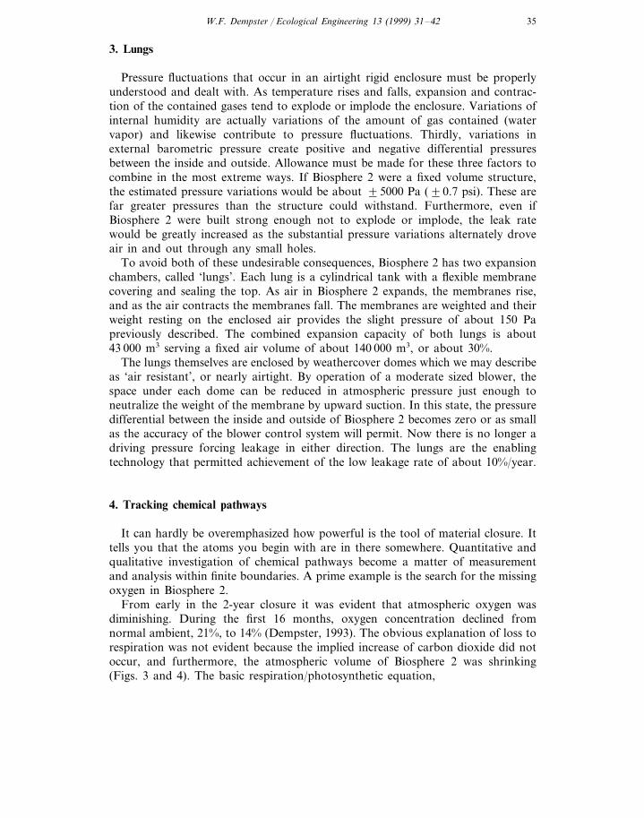
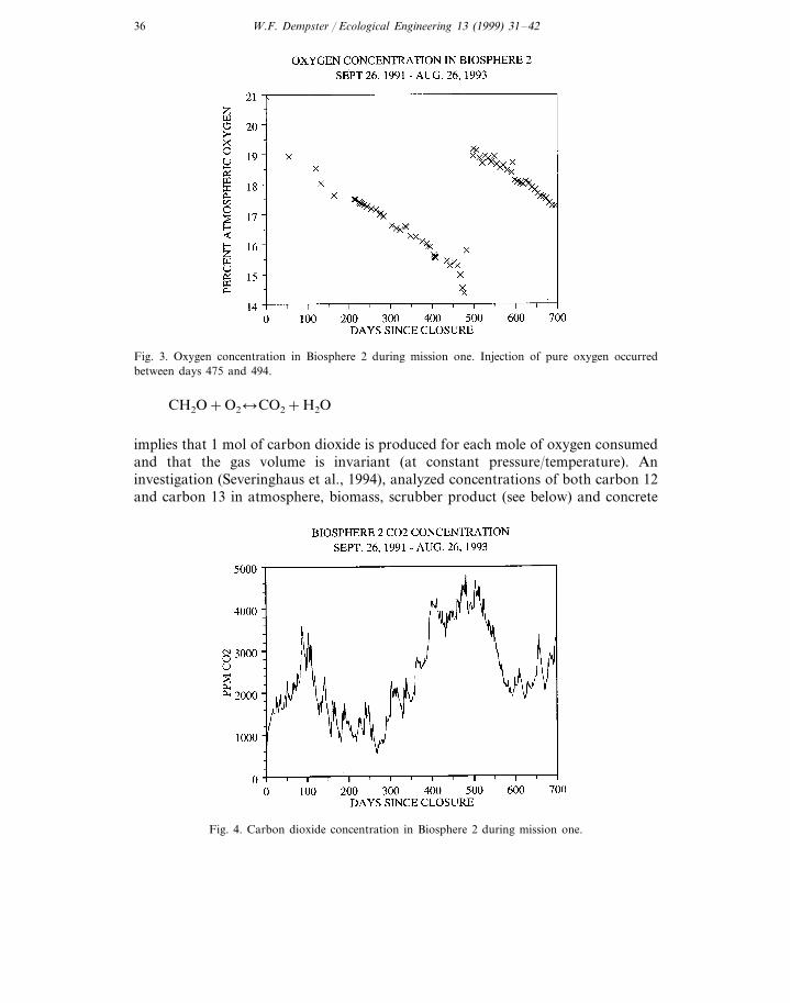
From early in the 2-year closure it was evident that atmospheric oxygen wasdiminishing. During the first 16 months, oxygen concentration declined fromnormal ambient, 21%, to 14% (Dempster, 1993). The obvious explanation of loss torespiration was not evident because the implied increase of carbon dioxide did notoccur, and furthermore, the atmospheric volume of Biosphere 2 was shrinking(Figs. 3 and 4). The basic respiration/photosynthetic equation,
W.F. Dempster / Ecological Engineering 13 (1999) 31–4236
Fig. 3. Oxygen concentration in Biosphere 2 during mission one. Injection of pure oxygen occurredbetween days 475 and 494.
CH2O+O2lCO2+H2O
implies that 1 mol of carbon dioxide is produced for each mole of oxygen consumedand that the gas volume is invariant (at constant pressure/temperature). Aninvestigation (Severinghaus et al., 1994), analyzed concentrations of both carbon 12and carbon 13 in atmosphere, biomass, scrubber product (see below) and concrete
Fig. 4. Carbon dioxide concentration in Biosphere 2 during mission one.

W.F. Dempster / Ecological Engineering 13 (1999) 31–42 37
inside Biosphere 2. It was determined that carbon dioxide from the atmosphere wasbeing captured by carbonation of concrete as in
CaO+CO2�CaCO3
on the order of 600 kmol, or 26 t distributed over about 15 800 m2 of exposedconcrete. Thus, the explanation of oxygen loss by respiration of organic matter inthe soil was reinstated. Photosynthesis was returning oxygen to the atmosphere, butthe rates of the two processes were not in balance. The method of investigationrested on the accountability inherent in a closed system.
In anticipation of seasonal imbalances between the rates of oxygen/carbondioxide production and consumption, a scrubber system was installed enabling theremoval of carbon dioxide from the atmosphere. The scrubber extracts carbondioxide by blowing air through a falling ‘rain’ of NaOH solution which producesthe reaction
2NaOH+CO2�Na2CO3+H2O
Subsequent addition of lime to the sodium carbonate solution precipitates thecarbonate as solid
Na2CO3+CaO+H2O�CaCO3+2NaOH
which returns the sodium hydroxide for reuse and results in a storable solid calciumcarbonate. Operation of the scrubber system captured about 98 kmol of carbondioxide (4.3 t) total for the two fall–winter periods during the 2 years of closurefrom September 1991 to September 1993.
An electric furnace was installed which was intended to dissociate calciumcarbonate at high temperature
CaCO3�CaO+CO2
If successful, this would have fully completed the cycles and returned carbondioxide and lime during summer months, but heating elements in the furnace failedand the completion of that cycle was unrealized during the 2-year closure.
5. Energy
The primary energy demand of Biosphere 2 is light for plant growth which,except for a relatively small supplement of artificial light added to the agricultureafter the 2-year mission, is provided by sunshine. The combined effects of lightabsorption and reflection by the glass and shading by the structure result in about45–50% of ambient incident light reaching the plants inside.
The largest demand for an artificial energy supply is maintenance of temperatureand humidity conditions. Biosphere 2, being a large glass airtight enclosure fullyexposed to Arizona solar radiation, can also be viewed as a moderately goodcollector of solar energy. It was estimated that equilibrium temperature inside on abright sunny summer day would be 65°C, easily fatal to plants and animals. The

W.F. Dempster / Ecological Engineering 13 (1999) 31–4238
summertime cooling requirement can reach about 35 000 000 kJ/h (2800 t). Thewintertime heating requirement can reach about 11 000 000 kJ/h.
Both heating and cooling are provided by hot and cold water circulated fromoutside through heat exchangers within Biosphere 2. These circulating energytransfer waters are rigorously sealed in closed piping systems to preclude anyleakage or commingling with any of the ecosystem waters. The water is markedwith a dye colorant to reveal leaks that might occur. Heating or cooling energy istransferred to Biosphere 2 by fan-forced air circulation across the heat exchangersin conventional air handlers. This air circulation is entirely internal to Biosphere 2but the air transfers energy to and from the externally supplied cold and hot water.
There are 25 air handlers placed throughout the planted biomes, each capable ofmoving varying airflow up to 24 m3/s (50 000 cubic feet per minute). About half theair handlers are for cooling only, the other half are capable of cooling andreheating which controls humidity by condensing moisture out of the air andreheating to the desired temperature. For example, if humid air is cooled to 4°C itcan hold only about 5 g of water vapor per kg of dry air (specific humidity=0.005).The same airstream reheated to 18°C now has a relative humidity of about 40%.The habitat section of Biosphere 2 which is mostly opaque is fitted with smaller airhandlers typical of commercial application.
Electrical power for fans, pumps, lights, tools, communications etc. is similarlysupplied from outside through airtight penetrations. The peak demand is about1500 kW, averaging 700 kW, and is distributed throughout as 480/277 V and208/120 V 3-phase and single phase power. An external energy center housesgenerators for on-site power generation, hot water boilers and ammonia-basedchillers. Ammonia was specifically selected to avoid the use of freons and theassociated hazard for earth’s ozone layer.
The transfer of heat from Biosphere 2 into cold water circulated from the energycenter in turn results in a large demand to reject heat from the energy center to thelocal environment. Heat rejection from the energy center is by evaporating water incooling towers. Average evaporation for the whole system was about 400 000 l/dayranging from about 100 000 l/day in winter to 750 000 l/day in summer.
Redundancy of energy systems is an important safety feature of Biosphere 2 sinceloss of electric power for internal air circulation or loss of cold or hot heat exchangewater could result in sudden and drastic loss of temperature control (Dempster,1991). The energy center was provided with three generators, 1500, 1500, and 2250kW plus connection to the external electric power grid. Although normal operationcombines power sources in excess of 1500 kW, any one of these four electric powersources alone could sustain the minimum necessary degree of operational control.Additionally, the power is delivered over two independent busses which in turndistribute to equipment which is interleaved in every area of Biosphere 2. Thus,failure of either power train will not result in catastrophic failure in any area insidethe enclosure.
Multiple generator systems serving a common load are vulnerable to domino-ef-fect failure if one generator fails which could leave the remaining generator(s)overloaded. To preclude this scenario, sensing equipment is in place to detect

W.F. Dempster / Ecological Engineering 13 (1999) 31–42 39
failure of one generator in the energy center and send a signal to Biosphere 2 toshed several major loads within a few tens of milliseconds. The shed loads can laterbe restarted in sequence once more generating capacity is brought on-line whichavoids a surge the power system couldn’t handle.
Redundancy in cooling water is achieved by supply of both chilled water andevaporatively cooled water through independent piping systems. Although normaloperation uses both cooled water and chilled water, the cooled water alone willsuffice to maintain a minimal degree of temperature control. This redundancy alsopays for itself because cooled water (by evaporation at the cooling towers) is far lessexpensive than chilled water (produced by compressive chillers). The warm airinside Biosphere 2 is cooled in two stages, first and mostly using the cooled water,then the chilled water. Thus, the inexpensive cooled water provides the largerportion of the energy transfer. If, instead, all cooling were provided by chilledwater, the fuel bill would perhaps be double the $1 million annual consumption.
Two of the three generators and the hot water boilers in the energy center arefired with natural gas for economical and relatively clean operation. However, inthe event of disruption of the gas supply, these machines are ‘dual fuel’ so they canbe fired on diesel fuel alone from storage tanks on site.
Waste heat in the exhaust stream and jacket water of the generators is capturedby an absorption chiller to produce chilled water for Biosphere 2. An insulatedchilled water storage tank packed with eutectic salts provides 54 GJ (4300 ton-hours) of chilling reserve. The combination allows the energy of waste heat fromnighttime generation to be used for cooling Biosphere 2 the following day. This wasfurther enhanced by an electric power buy–sell agreement with the local utilitycompany which increased the waste heat available for on-site cogeneration cooling.
6. Water system
Warm moist Biosphere 2 air in contact with a cold heat exchanger provides asteady stream of relatively high purity condensate water. Evapotranspiration fromplants and soils is continually loading the Biosphere 2 atmosphere with watervapor. Because the atmosphere is closed and the air handlers have capacity to limitthe atmospheric humidity, it follows that the supply of condensate water is equal tothe evapotranspiration (except for brief transients), thus assuring a water supply inbalance with water demand. Condensate collection in Biosphere 2 was on the orderof 20 000–40 000 l/day. A storage tank with a capacity of 870 000 l allows formanagement of transitory mismatches between the rate of condensation and thedelivery of irrigation water and also compensates for seasonal variation in themoisture content of the 30 000 t of soil. During the 2-year closure the tank rangedfrom full to less than a quarter full.
In wintertime, the air handlers supply heating rather than cooling and condensatemay be unavailable from the heat exchange coils. In this situation the cold glassenvelope serves to condense water from the warm humid air. A network of watercollection troughs at the edges of the panes of glass delivers condensate water to

W.F. Dempster / Ecological Engineering 13 (1999) 31–4240
tanks for subsequent delivery to irrigation and other uses. See also Dempster (1992)for further description and schematic diagram of the water systems.
On this scale of water production, the need for potable and hygienic water is onlya relatively small sidestream demand. The water was found to be clean enough fordirect human consumption although an ultraviolet sterilization system was includedas a precaution.
Toilet, hygiene and kitchen wastewaters are sent first to anaerobic holding tanksand then to a marsh bed where aerobic root zone bacteria break down wasteproducts to nutrients for supply to the agriculture system. This type of system hadbeen extensively developed by B.C. Wolverton at NASA Stennis Space Center(Wolverton, 1988).
7. Marine waters
The ocean and salt water marsh biomes comprise over 4 million liters and aremaintained separately from the fresh water systems. Continual water movement isnecessary to bring food supply to filter feeders and immobile species. To this end,systems for generating waves and currents within the ocean were developed.
The wave generator works by vacuum uplift of ocean water into a chamberelevated above the ocean surface. Release of the vacuum to atmosphere (withinBiosphere 2) allows the uplifted water to suddenly fall, propagating a wave acrossthe ocean. In addition, pumps circulate about 2500 l/min throughout the oceansystem.
The coral reef community is one of the most fragile ecosystems of Biosphere 2.Maintenance of low nutrient conditions is essential to prevent eutrophication andalgae blooms. A system of protein skimmers operated by airlift pumps brings excessproteins to a surface froth where it is removed and this system also adds to overallocean water circulation.
In anticipation of fresh water intrusion into the ocean waters, a special desalin-ization system was incorporated into Biosphere 2. Fresh water can enter the oceanby two routes; condensation dripping from the overhead glass in winter, andirrigation runoff from planting pockets on the cliff facing the ocean. Unless amatching extraction of fresh water (which would include evaporation) is taken fromthe ocean, the ocean basin will eventually overflow and/or fresh water will becomeprogressively unavailable. The desalination system is a flash evaporator that boilssalt water at low temperature (55°C) in a vacuum and recondenses the vapor intofresh water. The heat required to boil the salt water is exchanged from the hotwater externally supplied from the energy center. In this way, up to 15 l/min offresh water can be extracted from the ocean.
The pumps and piping of both marine and fresh water inside Biosphere 2 almostentirely use fiberglass or PVC construction to prevent corrosion. Even energy centerwater which is corrosion inhibited is carried in fiberglass piping because the outsideof the pipes are exposed to warm humid Biosphere 2 air (Dempster and Van Thillo,1993).

W.F. Dempster / Ecological Engineering 13 (1999) 31–42 41
8. Nerve system and communications
A multi-level computer sensing, control and data processing system is distributedamong many terminals both inside Biosphere 2 and outside at facilities on the site.These are linked together by an on-site network and together comprise the ‘nervesystem’ of Biosphere 2. Connections are networked to most of the business officesas well as to the technical staff offices.
Hundreds of sensors collect data on temperature, humidity, light intensity,atmospheric gas concentrations, the operating status of equipment and the like. Alldata is polled at 15 min intervals and logged to an ever increasing database.
Site-wide data communications are possible through the network, enablingsimultaneous access to the data base. Telephone, walkie-talkie radios and videoconnections are also heavily used means of communication between the inside andoutside of Biosphere 2. Meetings ‘at the window’ concurrent with a telephone onboth sides of the window or walkie-talkie added a personal dimension to inside–outside communications during the 2-year closure.
Control of equipment, particularly the air handlers that control internal temper-ature and humidity is possible from either inside or outside through the nervesystem. Temperature and humidity control is regarded as so important that twolevels of back-up are in place below the nerve system for control of the air handlers.The first back-up level is programmable controllers which normally receive theircontrol parameters from the higher level nerve system but which can be set tooperate in isolation with manual parameter entry. The second back-up level is theon-off-air volume control and water circulation valving on each individual airhandler which can be manually overridden from the programmable controllers.Manual intervention at the appropriate level can override a nerve system failure atany level. Each biome of Biosphere 2 is equipped with from three to nine airhandlers. Similarly, all the mechanical systems in Biosphere 2 and the energy centercan be operated manually to guard against catastrophic consequences of computerfailure.
9. Conclusions
As the discipline of biospherics emerges as a new field of scientific and technicalundertaking, a variety of closed systems will be necessary for many applications andexperimental programs. The payload of these systems will be ecosystems of varyingdegrees of complexity and sophistication, some of which will be irreplaceable andinvaluable for their contribution to understanding in the field. The engineeredenclosure and support systems will be challenged to meet requirements of closureand reliability in addition to services otherwise provided by nature. Biosphere 2 hasattempted to meet these challenges and hopefully the lessons learned will be appliedto future systems.

W.F. Dempster / Ecological Engineering 13 (1999) 31–4242
References
Dempster, W.F., 1991. Biosphere 2: design approaches to redundancy and back-up. In: 21st Interna-tional Conference on Environmental Systems. San Francisco, CA, July 1991, SAE Technical PaperSeries 911328.
Dempster, W., 1992. Water systems of Biosphere 2. Presented at the International Conference on LifeSupport and Biospherics, University of Alabama, Huntsville, February 20, 1992, Space BiospheresVentures, Oracle, AZ.
Dempster, W.F., 1993. Biosphere 2: System dynamics and observations during the initial two-yearclosure trial. In: 23rd International Conference on Environmental Systems, Colorado Springs, CO,July 12–15, 1993, SAE Technical Paper Series 932290.
Dempster, W.F., 1994. Methods for measurement and control of leakage in CELSS and their applicationand performance in the Biosphere 2 facility. Adv. Space Res. 14 (11), 331–335.
Dempster, W.F., Van Thillo, M., 1993. Maintenance and operational support characteristics ofBiosphere 2. AIAA 93-4181. Presented to AIAA Space Programs and Technologies Conference andExhibit, September 21–23, 1993, Huntsville, AL.
Folsome, C., Hanson, J., 1986. The emergence of materially closed system ecology. In: Polunin, N. (Ed.),Ecosystem Theory and Application, Wiley, New York.
Nelson, M., Dempster, W.F., 1996. Living in space: results from Biosphere 2’s initial closure, an earlytestbed for closed ecological systems on Mars, AAS 95-488. In: Stoker, C.R., Emmart, C. (Eds.),Strategies for Mars: A Guide to Human Exploration, vol. 86, Science and Technology Series,American Astronautical Society, Univelt, San Diego, CA, pp. 373–390.
Severinghaus, J.P., Broecker, W.S., Dempster, W.F., MacCallum, T., Wahlen, M., 1994. Oxygen loss inBiosphere 2, EOS. Trans. Am. Geophys. Union 75 (3) 33, 35–37.
Terskov, I.A., Gitelson, J.I., Kovrov, B.G., et al. 1979. Closed System: Man–Higher Plants (FourMonth Experiment) translation of Nauka Press, Siberian Branch, Novocibirsk, 1979, NASA-TM-76452.
Wolverton, B.C., 1989. Aquatic plant/microbial filters for treating septic tank effluent. In: Hammer,D.A., Constructed Wetlands for Wastewater Treatment, Lewis Publishers, Boca Raton, FL.
Zabel, B., Hawes, P., Stuart, H., Marino, B., 1998. Construction and engineering of a createdenvironment: Overview of the Biosphere 2 closed system. Ecol. Eng. 13, 43–63.
.
Related Documents