Behavior maps for online planning of obstacle negotiation and climbing on rough terrain Christian Dornhege and Alexander Kleiner Institut f¨ ur Informatik University of Freiburg 79110 Freiburg, Germany {dornhege, kleiner}@informatik.uni-freiburg.de Abstract — To autonomously navigate on rough ter- rain is a challenging problem for mobile robots, requir- ing the ability to decide whether parts of the environ- ment can be traversed or have to be bypassed, which is commonly known as Obstacle Negotiation (ON). In this paper, we introduce a planning framework that extends ON to the general case, where different types of terrain classes directly map to specific robot skills, such as climbing stairs and ramps. This extension is based on a new concept called behavior maps, which is utilized for the planning and execution of complex skills. Behavior maps are directly generated from ele- vation maps, i.e. two-dimensional grids storing in each cell the corresponding height of the terrain surface, and a set of skill descriptions. Results from extensive experiments are presented, showing that the method enables the robot to explore successfully rough terrain in real-time, while selecting the optimal trajectory in terms of costs for navigation and skill execution. I. INTRODUCTION To autonomously navigate on rough terrain is a chal- lenging problem for mobile robots, requiring the ability to decide which parts of the environment can be traversed or have to be bypassed, which is commonly known as Obstacle Negotiation (ON) [21]. While this problem has been mainly addressed for semi-rough terrain, e.g. within outdoor [13], [16], [19], and indoor scenarios [23], rough terrain, containing steep structure elements, demands robots to be explicitly aware of their context, thus allow- ing to execute specific skills with respect to the situation. In this paper, we introduce a planning framework that extends ON to the general case, where different types of terrain classes directly map to specific robot skills, such as climbing stairs and ramps. The framework is based on a new concept called behavior maps, which is utilized for the planning and execution of complex skills on rough terrain. Behavior maps are directly generated from elevation maps, i.e. two-dimensional grids storing in each cell the corresponding height of the terrain surface [3], [12], and a set of skill descriptions. Skill descriptions contain a set of fuzzy rules for the classification of structures they can handle, a set of spatial constraints encoding preconditions required for their execution, a 1 This research was partially supported by DFG as part of the collaborative research center SFB/TR-8 Spatial Cognition R7 cost function utilized for A* planning on the map, and the skill routine to be executed. According to these skill descriptions, elevation maps are segmented into different regions, where each region corresponds to a skill that can be executed therein. We utilize Markov Random Field (MRF) models, which are automatically constructed from the set of fuzzy rules, for detecting structure elements on the elevation map. Furthermore, behavior maps are augmented with preconditions, such as starting locations and angles, which are automatically generated from the sets of spatial constraints. The re- sulting 2D representation encodes context information of the environment, and can efficiently be utilized for the planning and execution of skills. The final system consists of four main modules, which are all executed in real-time during navigation: elevation mapping, terrain classification, skill planning, and motion control. Fig. 1. The Lurker robot climbing up a ramp during the Rescue Robotics Camp 2006 in Rome. We conducted extensive experiments within an in- door environment containing pallets and ramps, which was designed accordingly to the testing arenas build by NIST for evaluating robots for USAR (Urban Search And Rescue) [11]. Note that these kind of scenarios do not yet capture the true complexity of rough terrain found in real USAR situations. However, they provide a benchmark yearly increasing in difficulty for facilitating the stepwise development of autonomous robot mobility.

Welcome message from author
This document is posted to help you gain knowledge. Please leave a comment to let me know what you think about it! Share it to your friends and learn new things together.
Transcript
Behavior maps for online planning of obstacle negotiation andclimbing on rough terrain
Christian Dornhege and Alexander KleinerInstitut fur InformatikUniversity of Freiburg
79110 Freiburg, Germany{dornhege, kleiner}@informatik.uni-freiburg.de
Abstract—To autonomously navigate on rough ter-rain is a challenging problem for mobile robots, requir-ing the ability to decide whether parts of the environ-ment can be traversed or have to be bypassed, whichis commonly known as Obstacle Negotiation (ON). Inthis paper, we introduce a planning framework thatextends ON to the general case, where different typesof terrain classes directly map to specific robot skills,such as climbing stairs and ramps. This extension isbased on a new concept called behavior maps, whichis utilized for the planning and execution of complexskills. Behavior maps are directly generated from ele-vation maps, i.e. two-dimensional grids storing in eachcell the corresponding height of the terrain surface,and a set of skill descriptions. Results from extensiveexperiments are presented, showing that the methodenables the robot to explore successfully rough terrainin real-time, while selecting the optimal trajectory interms of costs for navigation and skill execution.
I. INTRODUCTION
To autonomously navigate on rough terrain is a chal-lenging problem for mobile robots, requiring the abilityto decide which parts of the environment can be traversedor have to be bypassed, which is commonly known asObstacle Negotiation (ON) [21]. While this problem hasbeen mainly addressed for semi-rough terrain, e.g. withinoutdoor [13], [16], [19], and indoor scenarios [23], roughterrain, containing steep structure elements, demandsrobots to be explicitly aware of their context, thus allow-ing to execute specific skills with respect to the situation.
In this paper, we introduce a planning framework thatextends ON to the general case, where different types ofterrain classes directly map to specific robot skills, suchas climbing stairs and ramps. The framework is basedon a new concept called behavior maps, which is utilizedfor the planning and execution of complex skills onrough terrain. Behavior maps are directly generated fromelevation maps, i.e. two-dimensional grids storing in eachcell the corresponding height of the terrain surface [3],[12], and a set of skill descriptions. Skill descriptionscontain a set of fuzzy rules for the classification ofstructures they can handle, a set of spatial constraintsencoding preconditions required for their execution, a
1This research was partially supported by DFG as part of thecollaborative research center SFB/TR-8 Spatial Cognition R7
cost function utilized for A* planning on the map, andthe skill routine to be executed. According to theseskill descriptions, elevation maps are segmented intodifferent regions, where each region corresponds to askill that can be executed therein. We utilize MarkovRandom Field (MRF) models, which are automaticallyconstructed from the set of fuzzy rules, for detectingstructure elements on the elevation map. Furthermore,behavior maps are augmented with preconditions, suchas starting locations and angles, which are automaticallygenerated from the sets of spatial constraints. The re-sulting 2D representation encodes context informationof the environment, and can efficiently be utilized forthe planning and execution of skills. The final systemconsists of four main modules, which are all executed inreal-time during navigation: elevation mapping, terrainclassification, skill planning, and motion control.
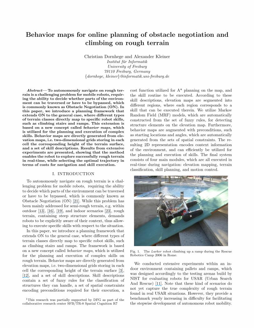
Fig. 1. The Lurker robot climbing up a ramp during the RescueRobotics Camp 2006 in Rome.
We conducted extensive experiments within an in-door environment containing pallets and ramps, whichwas designed accordingly to the testing arenas build byNIST for evaluating robots for USAR (Urban SearchAnd Rescue) [11]. Note that these kind of scenarios donot yet capture the true complexity of rough terrainfound in real USAR situations. However, they provide abenchmark yearly increasing in difficulty for facilitatingthe stepwise development of autonomous robot mobility.
Results from our experiments show that the robot wasable to successfully explore such environments in real-time, while selecting the optimal trajectory in terms ofcosts for navigation and skill execution.
Former work mainly focused on behavior-based ap-proaches for robot navigation on rough terrain. For ex-ample, Hebert and colleagues developed a tracked robotfor scrambling over rubble with autonomous navigationbased on visual servoing and stereo vision-based obstacleavoidance [9]. Ye and Borenstein extracted traversabilityfield histograms from elevation maps for obstacle avoid-ance on a Segway platform [22]. While purely behavior-based approaches are successful on moderately rugged3-D terrain, they might fail within densely structuredenvironments due to a limited lookahead needed forconcluding efficient sequences of skills.
Methods for terrain classification [13], [16], [19], [18]and terrain trafficability characterization [14] have beenextensively studied in the past. These methods mainlyfocus on the question whether a terrain feature can betraversed or has to be bypassed, e.g. they classify theterrain into classes such as road, grass, and rock.
The remainder of this paper is structured as follows. InSection II we describe the utilized hardware platform, inSection III we explain the construction of behavior maps,and in Section IV planning on these maps is described.Finally, we provide results from robot experiments inSection V and conclude in Section VI.
II. HARDWARE PLATFORM
Figure 1 shows the tracked Lurker robot, which isbased on the Tarantula R/C toy. Although based ona toy, this robot is capable of climbing difficult obsta-cles, such as stairs, ramps, and random stepfields [11].This is possible due to its tracks, which can operateindependently on each side, and the “Flippers” (i.e. thefour arms of the robot), which can freely be rotated at360◦. The base has been modified in order to enableautonomous operation. First, we added a 360◦ freelyturnable potentiometer to each of the two axes for mea-suring the angular position of the flippers. Second, weadded 10 touch sensors to each flipper, allowing the robotto measure physical pressure when touching the groundor an object.
Furthermore, the robot is equipped with a 3-DOFInertial Measurement Unit (IMU) from Xsens, allowingdrift-free measurements of the three Euler angles yaw,roll, and pitch, and two Hokuyo URG-X004 Laser RangeFinders (LRFs), one for scan matching, and one forelevation mapping, which can be tilted in the pitch anglewithin 90◦.
III. BUILDING BEHAVIOR MAPS
In this section we describe the process of buildingbehavior maps, which later serve as a basis for skill plan-ning and execution. Behavior maps are generated fromelevation maps, which are two-dimensional arrays storing
for each discrete location the corresponding height valueand variance. We utilize a method for real-time eleva-tion mapping on rough terrain that facilitates mappingwhile the robot navigates on uneven surfaces [12]. Themethod generates an elevation map by the successiveintegration of the robot’s three-dimensional pose andrange measurements of a downwards tilted Laser RangeFinder (LRF). In order to determine the height for eachlocation, endpoints from readings of the tilted LRF aretransformed with respect to the robot’s global pose, andthe pitch (tilt) angle of the LRF. Thereby the three-dimensional pose of the robot is tracked by integratingthe orientation measured by the IMU and a translationestimate generated by a visual odometry method. Fur-thermore, the three-dimensional pose is updated fromheight observations that have been registered on the map.
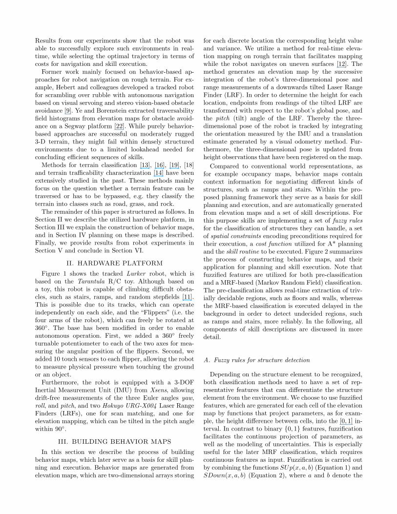
Compared to conventional world representations, asfor example occupancy maps, behavior maps containcontext information for negotiating different kinds ofstructures, such as ramps and stairs. Within the pro-posed planning framework they serve as a basis for skillplanning and execution, and are automatically generatedfrom elevation maps and a set of skill descriptions. Forthis purpose skills are implementing a set of fuzzy rulesfor the classification of structures they can handle, a setof spatial constraints encoding preconditions required fortheir execution, a cost function utilized for A* planningand the skill routine to be executed. Figure 2 summarizesthe process of constructing behavior maps, and theirapplication for planning and skill execution. Note thatfuzzified features are utilized for both pre-classificationand a MRF-based (Markov Random Field) classification.The pre-classification allows real-time extraction of triv-ially decidable regions, such as floors and walls, whereasthe MRF-based classification is executed delayed in thebackground in order to detect undecided regions, suchas ramps and stairs, more reliably. In the following, allcomponents of skill descriptions are discussed in moredetail.
A. Fuzzy rules for structure detection
Depending on the structure element to be recognized,both classification methods need to have a set of rep-resentative features that can differentiate the structureelement from the environment. We choose to use fuzzifiedfeatures, which are generated for each cell of the elevationmap by functions that project parameters, as for exam-ple, the height difference between cells, into the [0, 1] in-terval. In contrast to binary {0, 1} features, fuzzificationfacilitates the continuous projection of parameters, aswell as the modeling of uncertainties. This is especiallyuseful for the later MRF classification, which requirescontinuous features as input. Fuzzification is carried outby combining the functions SUp(x, a, b) (Equation 1) andSDown(x, a, b) (Equation 2), where a and b denote the
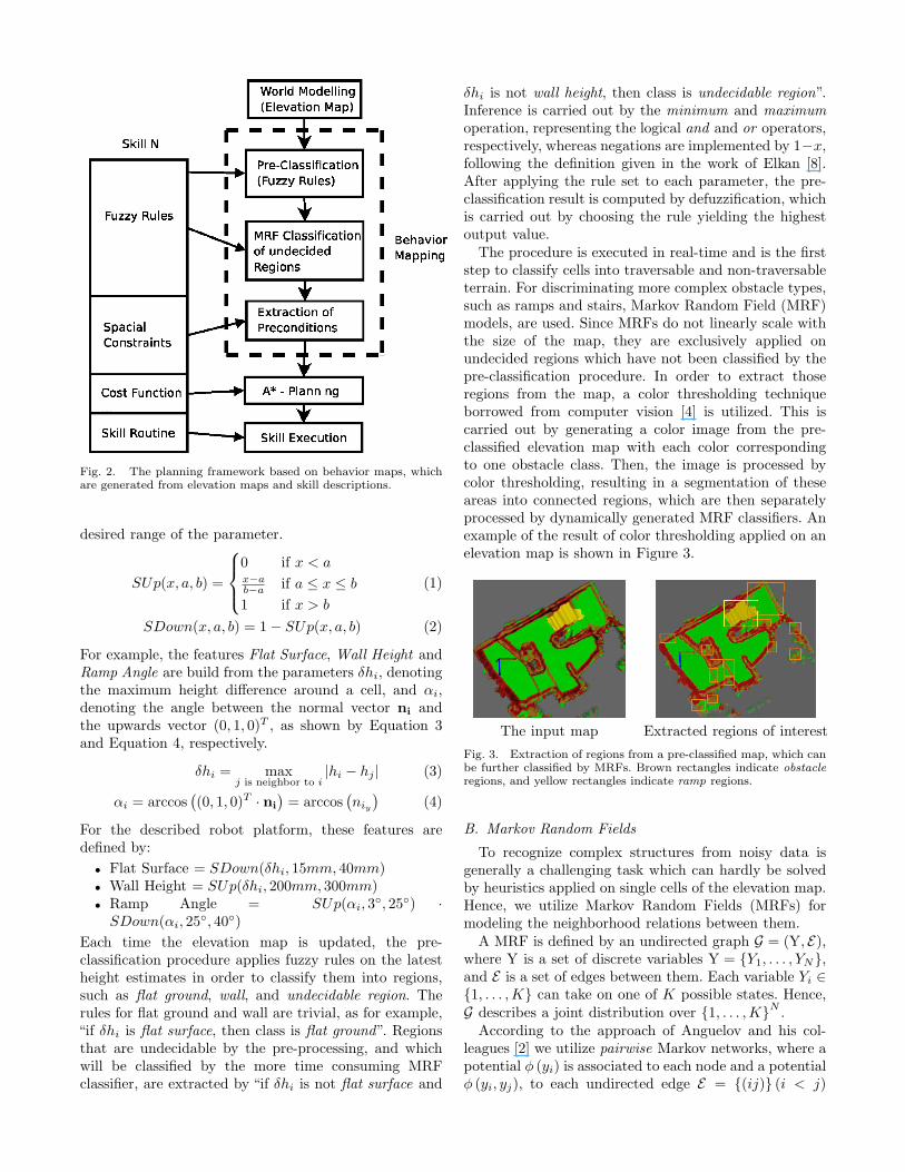
Fig. 2. The planning framework based on behavior maps, whichare generated from elevation maps and skill descriptions.
desired range of the parameter.
SUp(x, a, b) =
0 if x < ax−ab−a if a ≤ x ≤ b
1 if x > b
(1)
SDown(x, a, b) = 1− SUp(x, a, b) (2)
For example, the features Flat Surface, Wall Height andRamp Angle are build from the parameters δhi, denotingthe maximum height difference around a cell, and αi,denoting the angle between the normal vector ni andthe upwards vector (0, 1, 0)T , as shown by Equation 3and Equation 4, respectively.
δhi = maxj is neighbor to i
|hi − hj | (3)
αi = arccos((0, 1, 0)T · ni
)= arccos
(niy
)(4)
For the described robot platform, these features aredefined by:
• Flat Surface = SDown(δhi, 15mm, 40mm)• Wall Height = SUp(δhi, 200mm, 300mm)• Ramp Angle = SUp(αi, 3◦, 25◦) ·
SDown(αi, 25◦, 40◦)Each time the elevation map is updated, the pre-classification procedure applies fuzzy rules on the latestheight estimates in order to classify them into regions,such as flat ground, wall, and undecidable region. Therules for flat ground and wall are trivial, as for example,“if δhi is flat surface, then class is flat ground”. Regionsthat are undecidable by the pre-processing, and whichwill be classified by the more time consuming MRFclassifier, are extracted by “if δhi is not flat surface and
δhi is not wall height, then class is undecidable region”.Inference is carried out by the minimum and maximumoperation, representing the logical and and or operators,respectively, whereas negations are implemented by 1−x,following the definition given in the work of Elkan [8].After applying the rule set to each parameter, the pre-classification result is computed by defuzzification, whichis carried out by choosing the rule yielding the highestoutput value.
The procedure is executed in real-time and is the firststep to classify cells into traversable and non-traversableterrain. For discriminating more complex obstacle types,such as ramps and stairs, Markov Random Field (MRF)models, are used. Since MRFs do not linearly scale withthe size of the map, they are exclusively applied onundecided regions which have not been classified by thepre-classification procedure. In order to extract thoseregions from the map, a color thresholding techniqueborrowed from computer vision [4] is utilized. This iscarried out by generating a color image from the pre-classified elevation map with each color correspondingto one obstacle class. Then, the image is processed bycolor thresholding, resulting in a segmentation of theseareas into connected regions, which are then separatelyprocessed by dynamically generated MRF classifiers. Anexample of the result of color thresholding applied on anelevation map is shown in Figure 3.
The input map Extracted regions of interestFig. 3. Extraction of regions from a pre-classified map, which canbe further classified by MRFs. Brown rectangles indicate obstacleregions, and yellow rectangles indicate ramp regions.
B. Markov Random Fields
To recognize complex structures from noisy data isgenerally a challenging task which can hardly be solvedby heuristics applied on single cells of the elevation map.Hence, we utilize Markov Random Fields (MRFs) formodeling the neighborhood relations between them.
A MRF is defined by an undirected graph G = (Y, E),where Y is a set of discrete variables Y = {Y1, . . . , YN},and E is a set of edges between them. Each variable Yi ∈{1, . . . ,K} can take on one of K possible states. Hence,G describes a joint distribution over {1, . . . ,K}N .
According to the approach of Anguelov and his col-leagues [2] we utilize pairwise Markov networks, where apotential φ (yi) is associated to each node and a potentialφ (yi, yj), to each undirected edge E = {(ij)} (i < j)
between two nodes. Consequently, the pairwise MRFmodel represents the joint distribution by:
Pφ(y) =1Z
N∏i=1
φi(yi)∏
(ij)∈E
φij(yi, yj) (5)
where Z denotes a normalization constant, given by Z =∑y′
∏Ni=1 φi(y′i)
∏(ij)∈E φij(y′i, y
′j).
A specific assignment of values to Y is denoted byy and represented by the set
{yk
i
}of K · N indicator
variables, for which yki = I(yi = k). In order to foster
the associativity of the model, we reward instantiationsthat have neighboring nodes, which are labeled by thesame class. This is enforced by requiring φij(k, l) =λk
ij , where λkij > 1, for all k = l, and φij(k, l) = 1,
otherwise [17]. Inference is carried out by solving themaximum a-posterior (MAP) inference problem, i.e. tofind arg maxy Pφ (y).
For our specific problem, we define the node poten-tials φ (yi) by a vector of features, where each featureis produced by fuzzifying a parameter as defined inSection III-A. Likewise we define the edge potentialsφ (yi, yj) by a vector of features that reflect the spatialrelations between surface cells. More specific, we considerthe height difference δh = |hi − hj | between neighboringcells as an input parameter for features expressing thoserelations, as for example:
• Flat Transition = SDown(δh, 15mm, 40mm)• Obstacle Transition = SUp(δh, 25mm, 80mm) ·
SDown(δh, 200mm, 350mm)• Wall Difference = SUp(δh, 200mm, 300mm)
Given the node and edge potentials for each extractedregion of interest, one MRF graph is dynamically con-structed with each node connecting to the four closestneighbors in the vicinity. Note that the maximal numberof neighbors has to be limited due to the limited compu-tation time.
For the sake of simplicity potentials are representedby a log-linear combination log φi(k) = wk
n · xi andlog φij(k, k) = wk
e ·xij , where xi denotes the node featurevector, xij the edge feature vector, and wk
n and wke the
row vectors according to the dimension of node featuresand edge features, respectively. Consequently, we candenote the MAP inference problem arg maxy Pφ (y) by:
arg maxy
N∑i=1
K∑k=1
(wkn ·xi)yk
i +∑
(ij)∈E
K∑k=1
(wke ·xij)yk
i ykj . (6)
Equation 6 can be solved as a linear optimization prob-lem by replacing the quadratic term yk
i ykj with the
variable ykij and adding the linear constraints yk
ij ≤ yki
and ykij ≤ yk
j . Hence, the linear programming formulation
of the inference problem can be written as:
maxN∑
i=1
K∑k=1
(wkn · xi)yk
i +∑
(ij)∈E
K∑k=1
(wke · xij)yk
ij (7)
s.t. yki ≥ 0, ∀i, k;
∑k
yki = 1, ∀i;
ykij ≤ yk
i , ykij ≤ yk
j , ∀ij ∈ E , k,
which can, for example, be solved by the Simplex algo-rithm [7]. Furthermore, it is necessary to learn the weightvectors for the node and edge potential from data, whichhas been carried out by utilizing the maximum marginapproach recommended by Taskar et al. [17].
C. Encoding skill preconditionsDue to the fact that obstacles might not be traversable
from every point and every direction as flat areas are, weneed to detect transitions that reliably lead the robotonto the obstacle. Furthermore, it is necessary to deter-mine from this transitions the according preconditionsfor the skill execution, which are basically the startinglocation and starting orientation. Therefore, the user hasto define for each skill the specific type of transition theskill can traverse by spacial relationships.
The Allen’s Interval Calculus [1] defines qualitativerelationships among one dimensional intervals by 13base relations. Denoting the start and end points ofan interval a by a− and a+, respectively, the relations{meets, starts, finishes} can be defined by:
• a meets b: {(a, b) | a− < a+ = b− < b+}• a starts b: {(a, b) | a− = b− < a+ < b+}• a finishes b : {(a, b) | b− < a− < a+ = b+}
Using this subset of relations, a ramp transition can bedefined as {F meets R,F starts T,R finishes T}. Fig-ure 4(b) shows a floor-ramp transition that does not con-tain any other intervals besides floor (F) and ramp (R),while T stands for the interval containing all intervalsconsidered.
The clusters generated in Section III-A contain cellsbelonging to a specific class. To extract preconditionsfrom these cells, the following steps are performed: First,cells that are potentially part of a transition are se-lected. Second, straight lines from the selected cells areextracted, where starting and ending cells of these linesare determined according to the qualitative relationsdescribe above. In the following, these lines are termedtransition edges. Third, preconditions, i.e. the exactstarting locations for the skill execution, are computed.
For the extraction of suitable cells we select everycell that fulfills one of the meets rules defined by thequalitative relations. By this, cells that form a frontierfrom one classified region to another are selected, anal-ogous to the definition of frontier cells [20] that definethe frontier between unexplored and obstacle-free terrainwithin occupancy grids.
We assume that the transitions can be considered tobe straight lines and apply the Hough transform [10]
on the selected points to detect these lines. The Houghtransform represents a line in normal form, so that eachpoint (x, y) is lying on the straight that has an angle θto the x-axis and distance ρ to the origin:
x · cos θ + y · sin θ = ρ. (8)
The transformation uses an accumulator in (θ, ρ) spaceto count for each point (x, y) each corresponding pointin (θ, ρ). Consequently, the position (θ∗, ρ∗) with thehighest count represents the line that goes through mostpoints and thus is returned as the best possible linethrough the point set.
In order to check whether straight lines are transitionedges, the line’s cells have to be considered. For eachcell, this is accomplished by examining a line perpen-dicular to the potential transition edge and validatingthe spatial constraints on intervals along this line. Theseintervals represent adjoint cells of the same class andare constructed by concatenating adjoining cells of thesame class into the same interval. If the last cell of oneinterval lies next to the first cell of the following interval,we consider the intervals to fulfill the meets condition. Ifvalid cells are found over an extent of at least the robot’swidth, a transition edge has been detected.
Finally, the preconditions (xs, ys, φs) for the skill ex-ecution are calculated by projecting a starting point(xs, ys) perpendicular from the center of the transitionedge with a fixed offset in front of the obstacle. The start-ing direction φ is set perpendicular to the transition edgepointing towards the obstacle. Additionally, the signedheight difference hs between the transition edge and thefacing end of the obstacle, i.e. the height difference therobot has to overcome, is determined as a parameterfor the skill execution. This parameter indicates, forexample, whether a transition is directed upwards ordownwards, and thus influences the execution of the skill.
Each map cell surrounding the transition edge will beassociated with a transition edge object, which containsthe transition edge’s start and end point, as well as itspreconditions with hs and the skill function, thus formingthe behavior map.
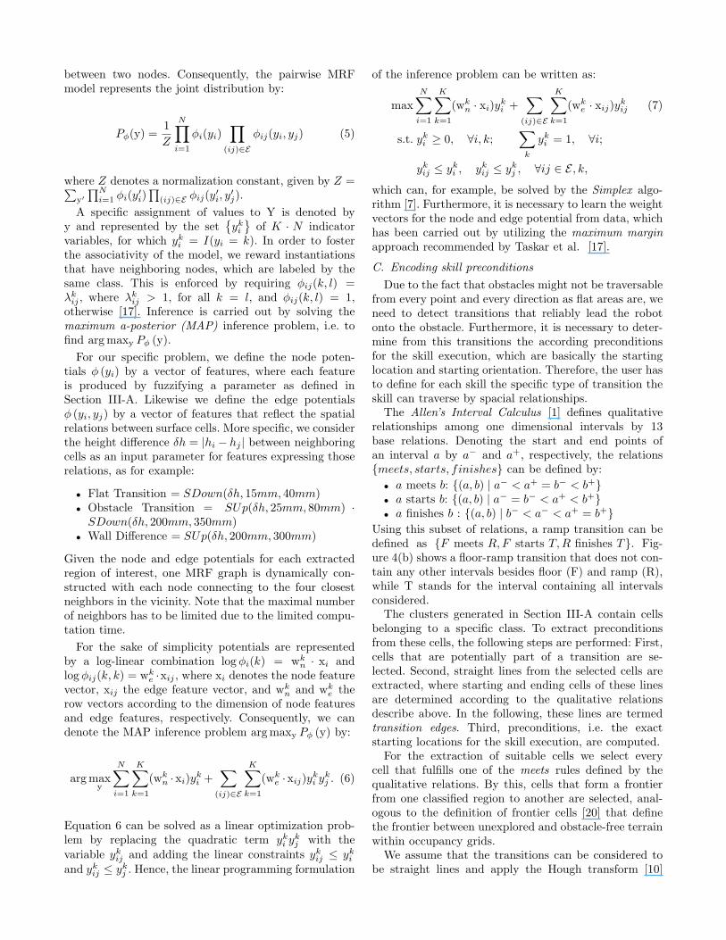
(a) (b)Fig. 4. Visualization of the process of determining skill pre-conditions: (a) Elevation map with ramp structure. (b) Classifiedelevation map with the detected classes floor (green), ramp (yel-low), and walls (dark red), detected transition edge (red), anddetected preconditions, which are the starting point (blue) andstaring direction (yellow).
As an example consider the analysis of a ramp
in Figure 4. Figure 4(a) shows a ramp structureon the elevation map. Figure 4(b) shows the clas-sified elevation map with the detected classes floor(green), ramp (yellow), and walls (dark red). Constraintshave been tested for each cell along a straight linethrough the region, resulting in the transition edge,marked in red. Note that along the transition edge the{F meets R,F starts T,R finishes T} rules are alwaysvalid. The detected preconditions are the starting point(xs, ys), marked as blue, and the starting direction φs
pointing upwards the ramp, marked as yellow.
IV. PLANNING AND SKILL EXECUTION
By utilizing behavior maps for planning and skillexecution we can employ two dimensional A* search forpath planning. This is due to the fact that the behaviormap itself contains the information of how to overcomean obstacle and thus there is no need to explicitly plancomplex robot skills in three dimensions. The A* algo-ritm performs informed search on graphs, which have acost function assigned to their edges. To guide the searchit uses a heuristic h(n) to estimate the distance of a noden to the goal and given this heuristic is admissable, i.e.,h(n) ≤ h∗(n) for all nodes n, with h∗ being the optimalheuristic, A* guarantees the optimality of a generatedpath [15].
To facilitate A* planning a graph has to be constructedfrom the behavior map. In a preprocessing step non-traversable cells are expanded by the robot’s radius toreflect the robot’s dimensions and base costs are set to1.0 for non-traversable cells, and 0.0 for traversable cells,respectively. In a second step these costs are blurredwith a Gaussian kernel to reward plans further awayfrom walls. A cell in the behavior map represents anode in the graph and a successor function, used byA*, returns for each node n, those nodes, to which n isconnected. To permit planning over transition edges andthus generate paths over obstacles, the successor functionfor node n returns all traversable neighbor nodes, whichare either of the same class as n or have a transitionedge assigned to them. Note that traversability is definedonly by the result of the expansion computed in the firstpreprocessing step, whereas the blurred costs are usedsolely as costs for the planning process.
Applying the A* search to the map might lead to plansthat traverse obstacles. Therefore, we need to take careof the fact that the costs for negotiating obstacles usuallydiffer from those given by the base costs. To represent thehigher amount of time spent during the skill executionon obstacles, and the increased risk of failure, a costfactor that leads to higher costs and thus to better suitedplanning results has to be provided by each skill.
The heuristic used for guiding the A* search is theEuclidean distance h =
√δx2 + δy2, which is commonly
employed. It is obvious that due to the increased costswhen traversing obstacles this heuristic is far from beingoptimal, but we refrain from changing the heuristic to
guarantee the optimality of planning. Practical exper-iments have shown that time needed for A* planningconstitutes no problem to the overall system.
The target selection process uses the concept of fron-tier cells [20], where a frontier cell is defined as beingtraversable and having, at least, one uninitialized neigh-bor. This ensures that the robot will explore unknownareas. We calculate the utility (Equation 9) based on therobots angle to the cell δθ and choose the frontier cellwith maximum utility, which prevents frequent turning,i.e. oscillation.
u = (SDown(δθ, 0◦, 180◦))2 (9)
We want to prevent the robot from choosing plans thatlead over obstacles, if there are still targets reachable byground exploration. Therefore, the planner accepts costsfor ground exploration until a certain threshold, beforepermitting planning over obstacles.
When executing the actual plan, the skill subroutinethat has to be executed by the controller is determinedfrom the robot’s current position on the behavior map.A transition edge stores the precondition that has to befulfilled first before executing the skill. Whenever thecontroller is queried to execute a new skill routine, it firstensures this precondition by turning towards the requiredstarting direction before calling the skill itself.
The skills (besides Ground Exploration) implementedin our system use as sensory input the robot’s pitch androll from the IMU, the angles of the flippers, and touchpoint sensors in the flippers that can give feedback aboutwhere the flipper has contact with an obstacle. Based onfeatures created from these sensors, a state machine isexecuted that can run different actions in parallel (e.g.driving forward while moving the rear flippers down).Currently our robots have the ability to lift up and drivedown from a pallet-like obstacle, drive a ramp and climbup stairs.
V. EXPERIMENTAL RESULTS
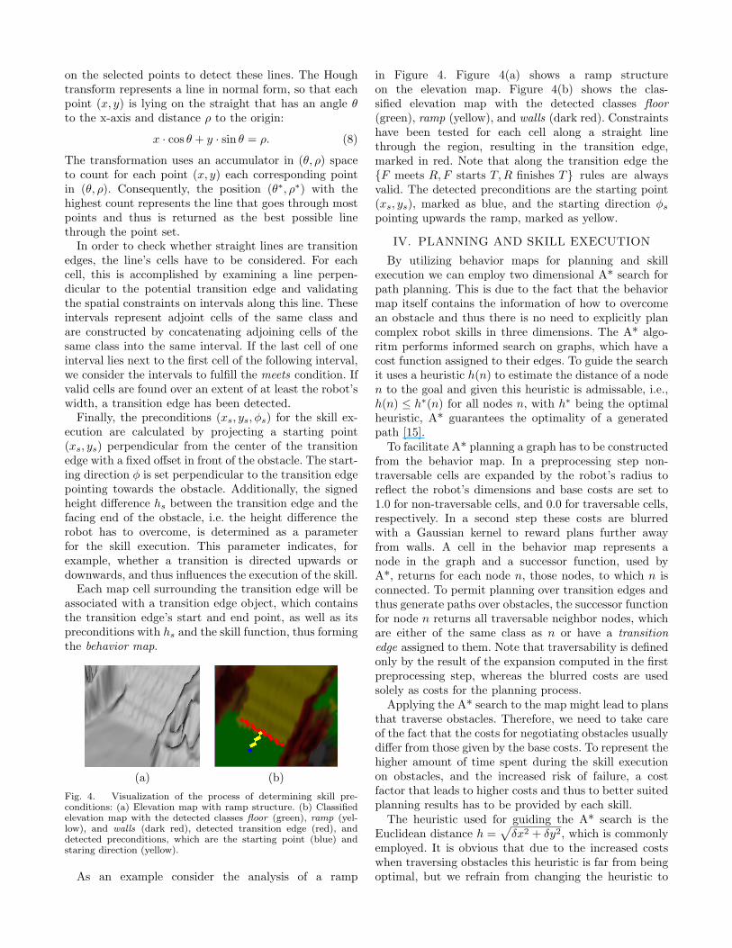
In order to evaluate the planning framework, a fullyautonomous exploration run has been conducted. Resultsfrom this run can be seen in Figure 5. The test rundemonstrates the system’s ability of online planning andobstacle negotiation during an exploration task on roughterrain. Figure 5(c) shows the exploration trajectory,crossing each obstacle only once, which covers the com-plete area. Due to the higher costs for obstacle climbing,the robot first explored flat areas before climbing overobstacles. Finally, a trajectory with a length of 23.00 mhas been traveled within 9 minutes and 55 secondsby the robot. Main factors to the overall computationtime were: the hough transform (63.94ms ± 0.78ms),the occupancy map blur (37.42ms ± 0.98ms) and theA* planning (32.26ms ± 4.76ms) on a AMD Athlon X23800+. Additionally, the MRF algorithm took 26.31s ±27.88s to classify extracted regions. Note that thesecomputation times have been measured for an update
(a) (b)
(c) (d)
Fig. 5. (a) Test arena for the exploration task. (b) The createdelevation map. (c) Classified map containing the trajectory of theexploration. (d) The behavior map showing the detected clusters ofinterest for obstacles (brown rectangles) and ramp (yellow rectan-gles) and recognized obstacle transitions (red). The robot startedexploring the area at the left, crossed the pallet, continued toexplore the center area and finally drove up the ramp.
of the full map consisting of 60, 000 cells. During onlineexecution, computation time is significantly lower sinceonly map regions that were updated beforehand by theelevation mapper have to be considered. Furthermore,the comparably higher amount of time needed for theMRF classification did not limit the system’s real-timeability. This is due to the fact that the robot was able torely on the pre-classification for planning and explorationwhile the MRF classification has been computed time-delayed in the background.
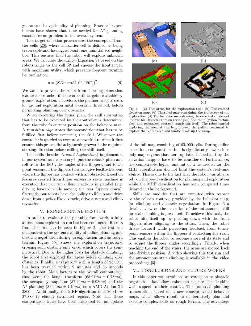
Skills are modules that are executed with respectto the robot’s context, provided by the behavior map,for climbing and obstacle negotiation. In Figure 6 adetailed view on the execution of the autonomous skillfor stair climbing is presented. To achieve this task, therobot lifts itself up by pushing down with the frontflippers after aligning to the stairs. Then, the robotdrives forward while perceiving feedback from touch-point sensors within the flippers if contacting the stair.This enables the robot to become aware of its state andto adjust the flipper angles accordingly. Finally, whenreaching the end of the stairs, the arms are moved backinto driving position. A video showing this test run andthe autonomous stair climbing is available in the videoproceedings [5].
VI. CONCLUSIONS AND FUTURE WORKS
In this paper we introduced an extension to obstaclenegotiation that allows robots to execute specific skillswith respect to their context. The proposed planningframework is based on a new concept called behaviormaps, which allows robots to deliberatively plan andexecute complex skills on rough terrain. The advantage
Fig. 6. Autonomous climbing of stairs.
of the described framework, i.e. the abstract definition ofskills, is that it can be extended by new skills, and alsobe adapted to other robot types.
Our results have shown that the final system imple-ments a truly autonomous robot that builds an eleva-tion map of the environment, classifies this map, andplans the execution of sequences of skills. In contrastto existing related work, the proposed system performsall these steps online during execution while overcomingrough terrain. This is a much harder problem thanprocessing data offline, e.g. to classify structures from apre-computed elevation map captured from fixed robotlocations. During online mapping, incremental states ofthe elevation map are only partially representing theenvironment due to the robot’s limited field of view.
In contrast to structures found in real disaster areas,the demonstrated experiments were carried out withina simplified environment. However, we are convincedthat, given reliably structure detection, the presentedframework is expendable towards more complex struc-ture components.
In future work, we will evaluate the application oflearning methods within skills by exploiting the contextinformation given by the behavior map. Furthermore, wewill extend the proposed approach towards a multi-levelrepresentation of behavior maps, allowing the robot toautonomously explore multistory buildings. One targetscenario in this context will be the benchmark presentedby the TechX challenge [6], which will be held 2008 inSingapore.
VII. ACKNOWLEDGMENTS
The authors gratefully acknowledge the work done byall members of the RescueRobots Freiburg team, particu-larly Rainer Kummerle and Bastian Steder.
References
[1] J. F. Allen. Maintaining knowledge about temporal intervals.Commun. ACM, 26(11):832–843, 1983.
[2] D. Anguelov, B. Taskar, V. Chatalbashev, D. Koller,D. Gupta, G. Heitz, and A.Y. Ng. Discriminative learning ofmarkov random fields for segmentation of 3D range data. InIEEE Int. Conf. on Computer Vision and Pattern Recognition(CVPR), San Diego, California, June 2005.
[3] J. Bares, M. Hebert, T. Kanade, E. Krotkov, T. Mitchell,R. Simmons, and W. R. L. Whittaker. Ambler: An au-tonomous rover for planetary exploration. 22(6):18–22, 1989.
[4] J. Bruce, T. Balch, and M. Veloso. Fast and inexpensive colorimage segmentation for interactive robots. In Proceedings ofIROS-2000, Japan, October 2000.
[5] C. Dornhege and A. Kleiner. Fully autonomous planning andobstacle negotiation on rough terrain using behavior maps. InVideo Proc. of the IEEE/RSJ Int. Conf. on Intelligent Robotsand Systems (IROS), 2007. To be published.
[6] DSTA. The techx challenge. Homepage: http://www.dsta.gov.sg/TechXChallenge/index.asp. Referenced 2007.
[7] Minieka E. and J.R. Evans. Optimization Algorithms forNetworks and Graphs. CRC Press, 1992.
[8] Charles Elkan. The paradoxical success of fuzzy logic. InProceedings of the Eleventh National Conference on ArtificialIntelligence, pages 698–703, Menlo Park, California, 1993.AAAI Press.
[9] M. Hebert, R. MacLachlan, and P. Chang. Experiments withdriving modes for urban robots. In Proceedings of SPIE, 1999.
[10] P.V.C. Hough. Methods and means for recognizing complexpatterns. In U.S. Patent 069654, 1962.
[11] A. Jacoff, E. Messina, and J. Evans. Experiences in deployingtest arenas for autonomous mobile robots. In Proc. of thePerMIS Workshop, Mexico, 2001.
[12] A. Kleiner and C. Dornhege. Real-time localization andelevation mapping within urban search and rescue scenarios.Journal of Field Robotics, 2007. Accepted for publication.
[13] R. Manduchi, A. Castano, A. Talukder, and Larry Matthies.Obstacle detection and terrain classification for autonomousoff-road navigation. Auton. Robots, 18(1):81–102, 2005.
[14] L. Ojeda, J. Borenstein, and G. Witus. Terrain trafficabilitycharacterization with a mobile robot. In G. R. Gerhart, C. M.Shoemaker, and D. W. Gage, editors, Unmanned GroundVehicle Technology VII, volume 5804, pages 235–243, 2005.
[15] Stuart J. Russell and Peter Norvig. Artificial Intelligence. AModern Approach. Prentice-Hall, 1995.
[16] A. Talukder, R. Manduchi, R. Castano, K. Owens,L. Matthies, A. Castano, and R. Hogg. Autonomousterrain characterisation and modelling for dynamic control ofunmanned vehicles. In IEEE/RSJ Int. Conf. on IntelligentRobots and Systems (IROS), pages 708–713, 2002.
[17] B. Taskar, V. Chatalbashev, and D. Koller. Learning associa-tive markov networks. In Proc. of the 21th ICML, 2004.
[18] S. Thrun, M. Montemerlo, H. Dahlkamp, D. Stavens, A. Aron,J. Diebel, P. Fong, J. Gale, M. Halpenny, G. Hoffmann, K. Lau,C. Oakley, M. Palatucci, V. Pratt, P. Stang, S. Strohband,C. Dupont, L.-E. Jendrossek, C. Koelen, C. Markey, C. Rum-mel, J. van Niekerk, E. Jensen, P. Alessandrini, G. Bradski,B. Davies, S. Ettinger, A. Kaehler, A. Nefian, and P. Mahoney.Stanley, the robot that won the DARPA grand challenge.23(9):655–656, 2006.
[19] N. Vandapel, D. Huber, A. Kapuria, and M. Hebert. Naturalterrain classification using 3-d ladar data. In IEEE Inter-national Conference on Robotics and Automation, volume 5,pages 5117 – 5122, April 2004.
[20] B. Yamauchi. A frontier-based approach for autonomousexploration. In CIRA, 1997.
[21] C. Ye and J. Borenstein. A new terrain mapping methodfor mobile robot obstacle negotiation. In Proc. of the UGVTechnology Conf. at the 2003 SPIE AeroSense Symposium,pages 21–25, Orlando, USA, 2003.
[22] C. Ye and J. Borenstein. Obstacle avoidance for the segwayrobotic mobility platform. In Proc. of the American NuclearSociety Int. Conf. on Robotics and Remote Systems for Haz-ardous Environments, pages 107–114, Gainesville, USA, 2004.
[23] C. Ye and J. Borenstein. T-transformation: a new traversabil-ity analysis method for terrain navigation. In Proc. of theSPIE Defense and Security Symposium, Orlando, USA, 2004.
Related Documents