1 Climbing Obstacle in Bio-robots via CNN and Adaptive Attitude Control M. Pavone * , P. Arena § , L. Fortuna § , M. Frasca § , L. Patan´ e § * Scuola Superiore di Catania, Via S. Paolo 73, 95123 Catania, Italy § Dipartimento di Ingegneria Elettrica Elettronica e dei Sistemi, Universit` a degli Studi di Catania, Viale A. Doria 6, 95125 Catania, Italy E-mail: [email protected] Abstract In this paper we introduce a novel control system architecture for hexapod robots. Our aim is to guarantee efficient horizontal walking and obstacle climbing via suitable postural adjustments. The control scheme takes its inspiration from recent neurobio- logical and kinematic observations of cockroaches walking on a treadmill and climbing over barriers. Based on a hierarchical and modular approach, the control architecture is divided into two levels. In the low level two parts working in parallel are present: rhythmic movements leading to gaits are performed by a Cellular Neural Network (CNN) playing the role of an artificial Central Pattern Generator (CPG), while a parallel PD attitude control system modulates (with adding terms) the CNN-CPG signals to achieve postural adjustments. The higher level, in turn, adds plasticity to the whole system; it is based on Motor Maps and maps sensory information in suitable attitude references for the low level PD attitude control. Tests performed with a dynamic model of hexapod have shown that after a training period the high level is able to enhance walking and climbing capabilities. I. I NTRODUCTION Explorative missions, e.g. to deliver a probe on a planetary surface or to inspect mined ground, represent a huge technological challenge [1]. Mechanical structure is the first issue to be addressed. Possible mechanisms capable of producing locomotion are: wheels, caterpillar treads and legs. Wheeled and tracked robots are much easier to design and to implement if compared with legged robots; nevertheless, they carry a set of disadvantages that hamper their use in more complex explorative tasks. Firstly, wheeled and tracked vehicles, even if designed specifically for harsh terrains, cannot maneuver over an obstacle significantly shorter

Welcome message from author
This document is posted to help you gain knowledge. Please leave a comment to let me know what you think about it! Share it to your friends and learn new things together.
Transcript

1
Climbing Obstacle in Bio-robots via CNN and
Adaptive Attitude Control
M. Pavone ∗, P. Arena §, L. Fortuna §, M. Frasca §, L. Patane §
∗ Scuola Superiore di Catania,Via S. Paolo 73, 95123 Catania, Italy
§Dipartimento di Ingegneria Elettrica Elettronica e dei Sistemi, Universita degli Studi di Catania,Viale A. Doria 6, 95125 Catania, Italy
E-mail: [email protected]
Abstract
In this paper we introduce a novel control system architecture for hexapod robots. Our aim is to guarantee efficient horizontal
walking and obstacle climbing via suitable postural adjustments. The control scheme takes its inspiration from recent neurobio-
logical and kinematic observations of cockroaches walking on a treadmill and climbing over barriers. Based on a hierarchical and
modular approach, the control architecture is divided into two levels. In the low level two parts working in parallel are present:
rhythmic movements leading to gaits are performed by a Cellular Neural Network (CNN) playing the role of an artificial Central
Pattern Generator (CPG), while a parallel PD attitude control system modulates (with adding terms) the CNN-CPG signals to
achieve postural adjustments. The higher level, in turn, adds plasticity to the whole system; it is based on Motor Maps and maps
sensory information in suitable attitude references for the low level PD attitude control. Tests performed with a dynamic model
of hexapod have shown that after a training period the high level is able to enhance walking and climbing capabilities.
I. INTRODUCTION
Explorative missions, e.g. to deliver a probe on a planetary surface or to inspect mined ground, represent a huge technological
challenge [1].
Mechanical structure is the first issue to be addressed. Possible mechanisms capable of producing locomotion are: wheels,
caterpillar treads and legs. Wheeled and tracked robots are much easier to design and to implement if compared with legged
robots; nevertheless, they carry a set of disadvantages that hamper their use in more complex explorative tasks. Firstly, wheeled
and tracked vehicles, even if designed specifically for harsh terrains, cannot maneuver over an obstacle significantly shorter

2
than the vehicle itself; a legged vehicle, on the other hand, could be expected to climb an obstacle up to twice its own height,
much like a cockroach can. Secondly, wheeled and tracked vehicles are also inherently less robust than those dependent on
legs. The loss of a single leg on a hexapod will result in only minimal loss in maneuverability, i.e. in a mechanical graceful
degradation; on a wheeled vehicle a damaged wheel could spell the end of mobility, and a damaged caterpillar tread almost
always results in catastrophic failure. Finally, legged vehicles are far more capable of navigating an intermittent substrate -such
as a slatted surface- than wheeled or tracked vehicles [2].
That is why the concept of a fully autonomous, mission capable, legged robot is acquiring an ever increasing interest in the
field of explorative robotics.
Given the preceding arguments for the use of legged locomotion in certain environments, one is left with the daunting task
of actually designing an efficient locomotion control for legged robots.
In this paper we propose an innovative control system architecture for hexapod robots basing on biological results discussed
in [3] and in [4]. Hierarchical organization and modularity have been taken as guidelines, accordingly with biological observa-
tions in insects [3]. Our aim is to guarantee efficient horizontal walking and obstacle climbing via suitable postural adjustments.
In fact, simulation tests performed with a dynamic model of hexapod robot revealed that, without postural control, walking
efficiency is low and just obstacles significantly shorter than the robot itself can be overcome.
Our control architecture is hierarchically divided into two levels. In the low level two different parts working in parallel
are present: rhythmic movements leading to gaits are performed by a Cellular Neural Network (CNN) playing the role of
an artificial Central Pattern Generator (CPG), while a parallel PD attitude control system modulates (with adding terms) the
CNN-CPG signals to achieve postural adjustments. The high level adaptively generates, basing on sensory feedback, postural
references for the PD attitude control.
The low level CNN-based CPG is discussed in details in [5], while the idea of a parallel PD attitude control is introduced
in [6]. The main focus of this work is, instead, on the high level. Basically the high level has to adaptively map input stimuli
into attitude references. The idea is to model the high level as a Motor Map whose “inputs” are sensory stimuli and whose
“outputs” are attitude references. Motor Maps are artificial neural networks based on a two-dimensional neural layer, on a set
of synaptic weights that determine the correspondence between input signals and neurons and on a set of output values [7].
The learning algorithm is the key to obtain a correct mapping between stimuli and actions. Thus, the high level learns from
the “experience” the suitable attitude references and confers plasticity to the whole system.
Arena et al. [8] successfully introduce a similar high-level layer with the aim of adapting leg coordination to a given speed
reference without any supervision. The focus here is, instead, on posture control.
3
We have built a dynamic model of hexapod robot basing on DynaMechs libraries [9]. Robot structure is an instantiation
of design concepts coming from cockroach structure. Simulations proved that after a training period the high level is able to
dramatically enhance walking and climbing capabilities.
This paper is articulated as follows. In Section II we discuss in details why postural adjustments are needed for efficient
obstacle overcoming. In Section III we discuss main features of cockroach structure in order to derive design concepts for
a simple, but effective dynamic model of hexapod robot. In Section IV we outline some of the most important features in
biological locomotion control and their implications in our work. In Section V we present our control system architecture,
while in Section VI we discuss simulation results. Finally, in Section VII, we draw our conclusions.
II. WHY AN ADAPTIVE POSTURAL CONTROL FOR HEXAPODS?
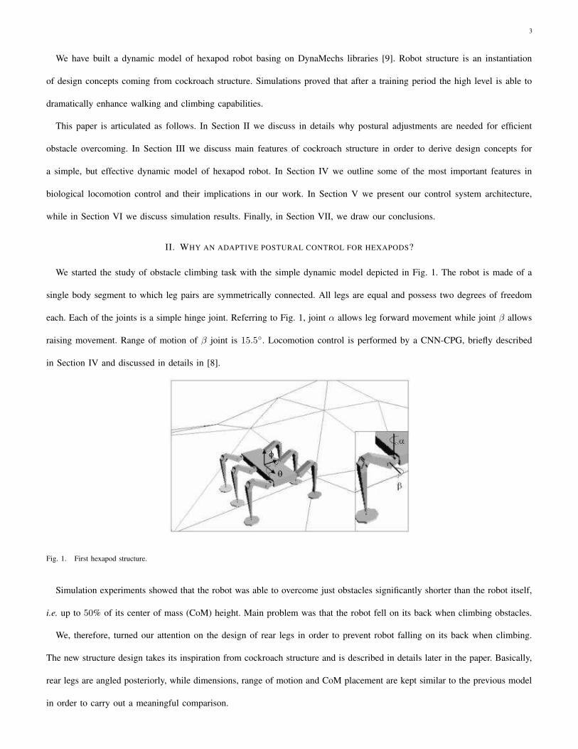
We started the study of obstacle climbing task with the simple dynamic model depicted in Fig. 1. The robot is made of a
single body segment to which leg pairs are symmetrically connected. All legs are equal and possess two degrees of freedom
each. Each of the joints is a simple hinge joint. Referring to Fig. 1, joint α allows leg forward movement while joint β allows
raising movement. Range of motion of β joint is 15.5◦. Locomotion control is performed by a CNN-CPG, briefly described
in Section IV and discussed in details in [8].
Fig. 1. First hexapod structure.
Simulation experiments showed that the robot was able to overcome just obstacles significantly shorter than the robot itself,
i.e. up to 50% of its center of mass (CoM) height. Main problem was that the robot fell on its back when climbing obstacles.
We, therefore, turned our attention on the design of rear legs in order to prevent robot falling on its back when climbing.
The new structure design takes its inspiration from cockroach structure and is described in details later in the paper. Basically,
rear legs are angled posteriorly, while dimensions, range of motion and CoM placement are kept similar to the previous model
in order to carry out a meaningful comparison.

4
Robot performance improved significantly: the robot was now able to overcome obstacles up to 90% of its center of mass;
nevertheless, this result is still far from insect performance.
In order to further improve performance, we studied in more details the kinematics of cockroaches climbing over barriers.
Watson et al. reported an exhaustive set of experimental data referring to kinematic changes associated with climbing in
cockroaches [4], [10]. Experimental data show that cockroaches do not deviate from normal running kinematics in surmounting
obstacles whose height is smaller than one reached by front legs during swing trajectory. On the other hand, several different
strategies have been observed when an hexapod insect faces obstacles whose top is beyond the height of front legs during swing
phase [4]. The most common one is the Rear Up strategy: when an obstacle is detected, an anticipatory postural adjustment
occurs. The pitch angle is increased before the collision and the insect is thus able to move the frontal legs on the step. The
animal performs this postural adjustment before front legs are placed on top of the barrier, principally by rotating the middle
legs in order to bring them perpendicular to the ground. In the subsequent phase, the animal’s CoM is raised upward with
little or no further change in body-substrate angle.
Thus, climbing high barriers is commonly accomplished by cockroaches in two stages:
• rearing stage: cockroaches change the body-substrate angle before any leg reaches the barrier;
• rising stage: animal’s CoM is raised upward.
The main point is that climbing does not require radical departures from running control mechanism, but just an anticipatory
postural adjustment. Since postural adjustment is initiated only after the height of the obstacle has been evaluated, it appears to
be directed, at least in part, by higher centers, as supraesophageal ganglia, driven by sensory feedback (presumably by visual
feedback and antennae) [4].
That’s why the idea of incorporating into the basic CNN-CPG locomotion control an adaptive attitude module able to handle
the Rear Up strategy. Adaptivity is needed since the robot in real applications should face a dynamic and noisy environment.
To the best of our knowledge, this is the first time that an adaptive attitude control is introduced ad hoc for obstacle
overcoming.
III. BIOLOGICAL STRUCTURE AND ROBOT DESIGN
Biological data of cockroaches inspired our hexapod model.
Each cockroach leg is divided into several segments, called, from the most proximal to the most distal segment, coxa,
trochanter, femur and tibia, and, at the end, into a series of foot joints collectively called tarsus [11]. Although front, middle
and rear legs have the same segments, they are different in lengths, yielding a ratio of front:middle:rear leg lengths of 1:1.2:1.7
[2], [12]. Leg pairs with different length provide superior agility. Cockroach legs articulate differently with the body, with the

5
front legs oriented almost vertically at rest and middle and rear legs angled posteriorly of about 30◦ and 50◦ from the vertical
[12]. This configuration provides efficient passive static stability [13].
Basing on these observations, we designed a robot model with a single body segment to which leg pairs are symmetrically
connected. Each leg is made of three segments, analogous to the three main segments of insect legs: coxa, femur, and tibia. The
coxa articulates with the body, the femur with the coxa, and the tibia with the femur. Each of the joints between leg segments
and between the coxa and the body is a simple hinge joint. Referring to Fig. 2, joint α allows leg forward movement, joint
β allows raising movement and, finally, joint γ guarantees roll and pitch control. For basic locomotion, joints α and β has to
perform a limit cycle in the joint space, while γ can be set at a constant value χref ; in particular, χref,ant = χref,med = 11.5◦
from the vertical for anterior and medium legs, while χref,post = 46◦ from the vertical for rear legs.
Rear legs are longer, yielding a ratio 1:1:1.5 and articulate with the body with an angle of 36◦ from the vertical, while the
other legs are oriented vertically. Robot CoM height, normalized with respect to the body length, is 0.5.
(a) Overall Structure (b) Leg - Detail
Fig. 2. Structure of the hexapod robot
This leg configuration confers a statically stable posture that guarantees a high margin of stability [13]. In fact the center
of mass of the system is always inside the support polygon, obtained connecting all the legs in stance phase. Therefore, this
design, inspired by the cockroach structure, facilitates the obstacle climbing task.
IV. CNN-CPG AND MOTOR MAPS
In this section, we summarize some results about CNN-based central Pattern Generator and Motor Maps, which are
fundamental to our approach. For a detailed treatise, the reader is referred to [8] and to the authoritative text by Ritter
[7].
A. Central Pattern Generator and CNN implementation
Most insects exhibit a hierarchical locomotion control and use a modular organization of the control elements. The activation
of the appropriate muscles in the legs and their coordination take place locally by means of groups of neurons functionally

6
organized in modules called Central Pattern Generators (CPG). The output signals of the CPG control directly the effector
organs. Distinct periodic patterns of leg movements, called gaits, are due to patterns of neural activity within the CPG [7].
The CPG receives stimuli from the high level control layers that monitor overall locomotion and take decisions about the high
level task for example by changing the locomotion gait.
Three different gaits are typically shown by hexapods during walking: fast, medium and slow gait. They are adopted under
different conditions to perform high speed locomotion (fast gait) or extremely stable and secure movements (slow gait).
The characteristics of these locomotion gaits can be rigorously defined through the concepts of cycle time, duty factor, and
leg phases. The cycle time is the time required for a leg to complete a locomotion cycle. The duty factor dfi is the time fraction
of a cycle time in which the leg i is in the power stroke phase. The leg phase ϕi is the fraction of a cycle period by which
the beginning of the return stroke of leg i lags behind the beginning of the return stroke of the left front leg (L1), chosen as
a reference. Basing on these quantities, a precise gait classification is shown in Tab. I:
TABLE I
CLASSIFICATION OF FAST, MEDIUM AND SLOW GAITS
Fast ϕL2 =1
2ϕL3 = 0 ϕR1 =
1
2ϕR2 = 0 ϕR3 =
1
2dfi = 1/2
Medium ϕL2 =3
4ϕL3 =
2
4ϕR1 =
2
4ϕR2 =
1
4ϕR3 = 0 dfi = 5/8
Slow ϕL2 =4
6ϕL3 =
2
6ϕR1 =
3
6ϕR2 =
1
6ϕR3 =
5
6dfi = 9/12
In our work, the CPG design has been accomplished by using Cellular Nonlinear Networks (CNNs). Following this design
strategy, the structure devoted to the generation of locomotion patterns for the six legs is composed by six identical nonlinear
oscillators, locally coupled, that directly control the stepping movements of robot legs. Each oscillator consists of a second-order
nonlinear circuit, made up of two elementary first-order CNN cells.
This approach has been called Multi-template Approach [14], because the desired locomotion pattern and switching among
patterns are achieved by means of a spatio-temporal algorithm implemented in the CNN structure and based on the use of
space variant templates.
Basically, this implementation relies on the principle that the dynamics of a same group of neural cells can be reorganized
by changing the synaptic connections. A high level control layer could be able to select the most suitable gait pattern by
changing the templates.
Main advantages of this approach are modularity, ease of design and flexibility. This technique has been used to control the
locomotion of several different bio-inspired robotic structures: hexapods, octopods and lamprey-like robots [5] and [15].
The parameters of the dynamical system constituting the CPG can be modified to obtain several distinct behaviors, similar

7
Fig. 3. Schematic representation of a motor map.
to those observed in real insects [5]. For example, step frequency can be modified by changing the time constant of the
system; moreover, by acting on the bias values of the cells, the dynamics of the system undergoes a bifurcation that allows
the integration of low level feedback, e.g. the elevator reflex, and even the implementation of a direction control.
B. Stimulus-Action relation and Motor Maps
In this paper, for the adaptive association between sensory feedback and attitude references taking place in the high level, we
rely on the Motor Map paradigm. Motor Maps are artificial neural networks based, like neural assemblies, on a two-dimensional
neural layer, on a set of input weights that determine the correspondence between input signals and neurons and on a set of
output values corresponding to the actions [7]. Formally, a motor map can be defined as an array of neurons mapping the
space V of the input patterns onto the space U of the output actions:
Φ : V 7→ U
A schematic representation of Motor Map is shown in Fig. 3.
The learning algorithm is the key to obtain a correct mapping between stimuli and actions. This is achieved by considering
an extension of the winner-take-all algorithm. The reward function, measuring how well the control is being performed, plays
the central role in Motor Maps learning. Basically, the learning process is articulated as follows:
• Step 1 – Determine the lattice site s (winner neuron) whose input weight vector best matches the input v(t) according
to some distance function ψ(·)
• Step 2 – Perform the control action using as output value:
ζ(t) = wwinner,out + asλ (1)
wwinner,out is the output value of the winner neuron, as is a parameter determining the mean value of the search step

8
for the neuron and λ is a Gaussian random variable with zero mean aimed to guarantee a random search for all possible
solutions.
• Step 3 – Compute the actual increase ∆R in the reward function; if ∆R exceeds the mean increase bs of the reward
function at lattice site s update the input weights wi,in and the output weights wi,out of neuron s and its neighboring
neurons as follows:
wi,in(t+ ∆t) = wi,in(t) + ηξ (v(t) − wi,in)
wi,out(t+ ∆t) = wi,out(t) + ηξ (f(t) − wi,out)
(2)
where η is the learning rate, ξ(·) is a neighborhood function and the index i spans through the neighbors of the winner
neuron s.
• Step 4 – Update the mean increase in the reward function:
bnew
s = bolds + γ(
∆R− bolds
)
(3)
where γ is the learning rate; update ai of neuron s and its neighboring neurons:
anew
i = aold
i + ηaξa(
a− aold
i
)
(4)
where ηa is the learning rate, ξa is the neighborhood function, a is a threshold value and the index i spans, again, through
the neighbors of the winner neuron s.
• Step 5 – Repeat steps 1) - 4). If a = 0 the learning phase stops when the weights converge.
It should be point out that no a priori information, except the form of the reward function, is taken into account during the
learning process.
V. CONTROL SYSTEM ARCHITECTURE
A. Locomotion strategy
In the attempt to emulate cockroach performance, we adopted a Rear Up strategy for obstacle overcoming. Thus, we
subdivided hexapod running in three main phases [4]:
• horizontal normal running;
• rearing phase;
• rising phase.

9
Fictitious antennae determine the actual phase. By denoting d as the (signed) distance, normalized with respect to the body
length, between obstacle edge and robot CoM, and by considering for simplicity just one obstacle, we define:
d > 1 : cruise phase
0 < d < 1 : rearing phase
−0.5 < d < 0 : rising phase
(5)
B. Control system: low level
Rhythmic movement generation is achieved through a CNN-CPG. The CNN-CPG is made of six second order neurons, each
one controlling through its two outputs y2
CPG and y1
CPG the joints α and β of one of the six legs. For simplicity the CPG has
not been integrated with local reflexes, that could indeed guarantee more agility and flexibility [16]. Moreover, the high-level
module that should control the CPG for example by changing the locomotion gait has not been implemented. Therefore, without
external control, the CPG provides a fixed gait. In particular, we assumed a medium gait.
In order to provide an attitude control, we add in parallel to the CNN-CPG an attitude control based on PD controllers. The
attitude control modulates, according to some attitude references, the CNN-CPG signals by adding biases, (i.e. by changing
their average values).
In detail, attitude control is made of two PD controllers: the former for the roll control, the latter for the pitch control.
Basically, the posture control is achieved by adding a bias in anti-phase for the left and right side (roll control) or for the front
and back part (pitch control).
To be more explicit, the attitude control acts biasing the mean values of α and β joints as follows:
αL1 = y1
CPG,L1 αR1 = y1
CPG,R1
βL1 = y2
CPG,L1 + broll + bpitch βR1 = y2
CPG,R1 − broll + bpitch
γL1 = χref,ant − broll − bpitch γR1 = χref,ant + broll − bpitch
αL2 = y1
CPG,L2 αR2 = y1
CPG,R2
βL2 = y2
CPG,L2 + broll βR2 = y2
CPG,R2 − broll
γL2 = χref,med − broll γR2 = χref,med + broll
αL3 = y1
CPG,L3 αR3 = y1
CPG,R3
βL3 = y2
CPG,R3 + broll − bpitch βR3 = y2
CPG,R3 − broll − bpitch
γL3 = χref,post − broll + bpitch γR3 = χref,post + broll + bpitch
(6)

10
Fig. 4. Block scheme of the attitude control integrated with the Central Pattern Generator.
where αi, βi and γi are, respectively, coxa, femur and tibia joint angles for leg i, while χref,i is the reference angle for the
tibia joint, as discussed above.
PD gains were found through an iterative process, following classical empirical methods for standard regulator parameter
tuning. PD gains are:
Kproll = 3 Kdroll = 1.5
Kppitch = 5 Kdpitch = 4
(7)
Our structure efficiently damps oscillations; anyway, in order to avoid impulse-like noise effects in the control loop, we
considered a saturation on the control voltage. In a real implementation, an anti-windup configuration should be also used.
Fig. 4 shows the CNN-CPG working in parallel with the attitude control. The C unit just combines signals according to Eq.
6.
This control scheme, henceforth called scheme I, was successfully applied to hexapod robots as discussed in [17], where
the target was to maintain the body in a horizontal position during walking on sloping planes or uneven terrains. In that case
attitude references for the PD controllers were trivial (roll angle θd = 0 and pitch angle ϕd = 0) and an higher control was
not needed.
C. Control system: high level
To implement Rear Up strategy, a time-varying pitch reference driven by sensory feedback is needed. Therefore we introduce
in the Scheme I a high level whose aim is exactly to provide pitch reference on the basis of antennae stimuli. In particular we
assume that antennae are able to measure distance from an obstacle and its height.
The association between obstacle height and pitch reference during rearing phase needs to be adaptive, since in real
applications the robot should face a dynamic environment. Motor Maps provide an ideal framework in this context: they
are in fact able to adaptively map input stimuli into actions. Thus, we added to the control scheme I a higher-level module

11
Fig. 5. Block scheme of the MMC integrated with the attitude control unit and the Central Pattern Generator.
based on Motor Maps, henceforth called Motor Map Controller (MMC). The overall control scheme, henceforth called Scheme
II, is depicted in Fig. 5.
Interestingly, a time-varying pitch angle can also be exploited to achieve speed control, since, for a given gait, attitude
changes imply a slightly different velocity. A similar idea is suggested in [18].
Thus, the MMC adaptively establishes reference pitch angles for the inner attitude control loop during cruise, rearing and
rising phases. Roll angle reference is, obviously, kept constant θd = 0.
The MMC is made of three subunits: two different Motor Maps and one cell containing a fixed pitch reference for the rising
stage; in fact, during rising stage, pitch reference is constant [4]. Former Motor Map (Cruise Motor Map) is aimed at cruise
control and has as input the reference speed and as output the pitch reference; latter Motor Map (Rearing Motor Map) controls
the rearing stage and has as input the obstacle height, as evaluated by antennae, and as output the pitch reference.
The following correspondence holds:
• cruise phase ⇒ reference established by Cruise Motor Map
• rearing phase ⇒ reference established by Rearing Motor Map
• rising phase ⇒ reference established by cell value
Thus, switching between subunits is achieved basing on obstacle-robot distance information coming from antennae, according
to Eq. 5.
We set the cell value at 5◦, according to [4].

12
D. Control system: Motor Map structure
Cruise Motor Map has as input the reference speed and as output the pitch reference; Rearing Motor Map controls the
rearing stage and has as input the obstacle height, as evaluated by antennae, and as output the pitch reference.
Cruise Motor Map and Rearing Motor Map are structurally identical and possess the same learning parameters. In detail,
each Motor Map is made of just n = 9 neurons, since the presence of a stabilizing inner loop allows the MMC to have
good performance even with a small number of neurons; few neurons imply a faster convergence of the algorithm. In order to
simplify the learning phase, we have considered a pure winner-take-all strategy by selecting unitary neighborhood functions
ξ(·) and ξa(·). The threshold value is a = 0.01, so that, after the learning phase, a residual plasticity for a later re-adaptation
is guaranteed. The learning rate is η = 0.5 as a trade-off between speed and accuracy of learning, while the two adaptive rates
are γ = 0.1 and ηa = 0.02.
Definition of the reward function for the Cruise Motor Map is straightforward:
Reward = −(vref − v)2 (8)
where vref is the reference speed and v is the actual speed (average value over three complete cycle times).
A natural choice for the reward function for the Rearing Motor Map is:
Reward = −(hobs − h)2 (9)
where hobs is the obstacle height as evaluated by antennae and h is the maximum height reached by front leg tarsi during
swing trajectory.
Finally, since in the Scheme II there is no feedback with ground contact, during the rising stage front legs could be not in
contact with ground; consequently, forward thrust could be not effective. In order to close the loop between ground contact
and front legs, we adjusted the pitch bias value for front legs as follows:
bpitch,front = kσbpitch (10)
where bpitch is the bias value determined by the PD pitch controller, k = 0.05 is a gain and σ is a counter incremented or
decremented at each integration step if a ground contact event has not or has happened.
VI. SIMULATION RESULTS
We validated the proposed control system architecture on a framework for dynamic simulation, based on DynaMechs libraries
[9]. We took in consideration all robot dynamical properties such as weights and inertia as well as motor properties. Overall

13
system differential equations (both robot dynamics and CNNs) have been integrated with a fourth order Runge-Kutta integration
algorithm. In detail, at each step:
1) CNNs are integrated;
2) Motor Maps are evaluated and updated;
3) robot dynamics is integrated.
A. Motor Maps training
In a preliminary phase, the MMC has been trained in the two functionally different tasks: cruise phase and rearing phase.
1) Cruise Motor Map training: Fig.6 shows Cruise Motor Map learning; henceforth speed is normalized with respect to
the body length and is expressed with respect to the time units used in simulation. Firstly reference speed is set to v = 0.15.
As shown in Fig. 6, actual speed approaches the reference speed at t ' 1.5 after a quite long transient, due to the fact that the
network is at the beginning of the learning phase. Then, reference speed is switched to v = 0.17; since the same neuron, now
well trained, is selected, actual speed approaches reference speed after a very fast transient. At t = 2.4 reference speed is again
switched, now to the value v = 0.29. Several different references are thus presented to the Motor Map until an exhaustive set
of speeds has been learnt.
As we can see from Fig. 6, there is overall a good agreement between reference speed and actual speed, except for the
reference speed v = 0.3; this is due to the fact that, for the given structure and gait (medium gait as stated above), reaching a
speed beyond vmax = 0.27 is not feasible. In this case, the motor map can only guarantee the highest achievable speed.
Moreover, it is worth noting how, at the end of the training phase, precisely at t ' 9.6, after switching, actual speed is
immediately close to reference speed; the remaining error slowly tends to zero, thanks to the residual plasticity guaranteed by
the choice adopted for the learning threshold value a.
In Fig. 7 robot pitch angle during training phase is shown. We can observe that during the time interval T = [0 1.5], when
the speed reference v = 0.15 has to be learnt as we can observe in Fig. 6, a negative pitch angle ϕ ' −18◦ is achieved. This
result holds also for the other low speed references. Thus, we infer that low speed references require a negative pitch angle.
Overall, pitch angle varies in the range −18◦ ÷ 12◦, values close to the experimental data reported for the cockroaches in
[4].
2) Rearing Motor Map training: In Fig. 8 training results for the Rearing Motor Map are shown. Obstacle height is as usual
normalized with respect to the CoM height. Basically, we can observe a similar behavior: at the beginning of the learning,
transient phase is long and discrepancy between mean actual value and reference value is considerable. At the end of the
learning, instead, transient phase is very short and there is not significant discrepancy between actual and reference values.

14
Fig. 6. Training of the Cruise Motor Map. The average value of robot speed (solid line) is in agreement with the reference speed (dashed line); the instant
value of the speed is also shown. Speed is normalized with respect to the body length and is expressed with respect to the time units used in the simulation.
Fig. 7. Pitch angle during Cruise Motor Map training. The angle is in degree.
The considerable errors corresponding to the references h = 0.6 and h = 0.96 (indicated by arrows in Fig. 8 ) are again due
to physical limitations of the given structure.
B. Obstacle climbing
We tested climbing capabilities with obstacles whose height ranges in the interval 0.6 ÷ 1.8 and whose slope is 85◦.
• Height 0.6÷ 0.8 – In all tests the robot directly placed its legs on the top of the obstacle and successfully climbed over
the barrier.
• Height 0.8 ÷ 1.4 – The robot can not directly place front legs on the top of the obstacle. Nevertheless the hexapod was
in all tests able to efficiently exploit the slope to place after 2 ÷ 3 cycle times its legs on the top and thus able to climb
over obstacle.
• Height h > 1.4 – Robot started failing; it was unable to climb over barriers higher than 1.7.
In Fig. 9 the climbing progression for a 1.4 obstacle is shown. Videos are available at the following URL [19].

15
Fig. 8. Training of the Rearing Motor Map. The average value during reference learning of front leg maximum elevation (solid line) is in agreement with
the reference elevation (dashed line). Obstacle height is normalized with respect to mass center height
(a) Approach (b) Rearing phase (c) Front leg on barrier top
(d) Rising stage (e) Forward thrust (f) Cruise phase
Fig. 9. Sequence of snapshots showing the behavior of the hexapod when the MMC is applied to accomplish obstacle climbing task.
C. Obstacle climbing over uneven terrains
We tested climbing capabilities also over uneven terrains, since terrains are harsh and uneven in real situation. We considered
a mean roughness equal to 0.125 with a maximal value of 0.25 (height normalized with respect to the mass center height).
Simulations showed that now the robot can negotiate obstacles with a reference height up to 1.2, that corresponds to a mean
actual height equal to 1.325 (reference height plus mean roughness). Thus, robot climbing performance, in this simple but
realistic roughness condition, decreases just slightly. In Fig. 10 the climbing progression for a 1.2 obstacle is shown. Videos
are available at the URL [19].

16
(a) Rearing phase (b) Rising stage (c) Cruise phase
Fig. 10. Climbing an 1.2 obstacle over uneven terrain.
D. Discussion
Experimental results show that the Cruise Motor Map is able to guarantee a reference speed through postural adjustments.
More importantly, with the proposed structure and control architecture the hexapod is now able to successfully overcome
obstacles with height up to 140 % of its CoM height (or equivalently up to 140 % of its front part height since CoM height
is virtually equal to front part height). In Section II we discussed how a simple structure with equal legs guarantees obstacle
overcoming up to 50% of robot CoM, while a bio-inspired structure guarantees obstacle overcoming up to 90%. Thus the
MMC control increases robot performance of 55%.
We also showed that climbing performance just slightly decreases when an uneven terrain with a reasonable roughness is
taken into account.
A comparison with other robots is difficult, since efficiency of a control module should be evaluated by testing the same
structure with and without this module, and not by comparing robots with different structures. Anyway, just to have an idea
of other robot performance, robot RHex [20] is able to negotiate obstacles high 130% of front part height, while Sprawlita
[18] is able to negotiate obstacles high 100% of front part height (RHex and Sprawlita are to date among the most efficient
six-legged runners).
Results are therefore encouraging and we plan to implement this control structure in a real robot.
VII. CONCLUSIONS
In this paper a control scheme based on self-organizing dynamical systems and Motor Maps is applied to the tasks of
horizontal walking and barrier overcoming.
Robot design takes into account biological principles, with a particular emphasis on rear leg design. In fact, obstacle
overcoming is a complex task and requires a detailed design of both mechanical structure and control architecture.
The control architecture is based on the biological paradigm of CPG and is divided into two levels. In the low level two
parts working in parallel are present: rhythmic movements leading to gaits are performed by a Cellular Neural Network (CNN)

17
playing the role of an artificial Central Pattern Generator (CPG), while a parallel PD attitude control system modulates (with
adding terms) the CNN-CPG signals to achieve postural adjustments. The higher level, in turn, adds plasticity to the whole
system; it is based on Motor Maps and maps sensory information in suitable attitude references for the low level PD attitude
control. The presence of an inner stabilizing attitude control loop allows to speed up the initial phase in which the Motor Maps
self-organize on the basis of a reward function, and at the same time allows to keep small the number of Motor Map neurons
needed for the task.
Results are encouraging: thanks to the innovative attitude control, the robot is now able to successfully overcome obstacles
up to 140% of its CoM height, thus improving its performance of 55%.
A Motor Map made of a small number of neurons can be implemented on a microcontroller or on a FPGA-based architecture,
whereas a VLSI implementation of the low level CPG-based control has been already introduced in [5]. Furthermore the whole
architecture can be integrated on an autonomous hexapod robot that represents a suitable solution for explorative missions on
harsh terrains without man control.
ACKNOWLEDGMENT
This work was supported by the Italian Ministero dell’Istruzione, dell’Universita e della Ricerca (MIUR) under the PRIN
project “Innovative Bio-Inspired Strategies for the Control of Motion Systems” and by the EU under the project FP6-004690
“Spatial-temporal Patterns for action oriented perception in roving robots” (SPARK).
REFERENCES
[1] R. D. Quinn, G. M. Nelson, and R. J. Bachmann, “Toward mission capable legged robots through biological inspiration”, Autonomous Robots, vol. 11,
pp. 215–220, 2001.
[2] D. Kingsley, R. Quinn, and R. Ritzmann, “A cockroach inspired robot with artificial muscles”, in International Symposium on Adaptive Motion of Animals
and Machines (AMAM), Kyoto, Japan, 2003.
[3] G. M. Shepherd, “Neurobiology”, Oxford Univ. Press, 1997.
[4] J. T. Watson, R. E. Ritzmann, S. N. Zill and S.J. Pollack, “Control of obstacle climbing in the cockroach, Blaberus Discoidalis, I. Kinematics”, J. Comp.
Physiol. A, 188, pp. 39–53, 2002.
[5] M. Frasca, P. Arena, L. Fortuna, “Bio-Inspired Emergent Control Of Locomotion Systems”, World Scientific Series on Nonlinear Science, Series A - Vol.
48, 2004.
[6] P. Arena, F. Conti, L. Fortuna, M. Frasca, and L. Patane, “Nonlinear networks to control hexapod walking”, Nonlinear Dynamics of Electronics Systems,
2003.
[7] H. Ritter, T. Martinetz and K. Schulten, “Neural computing and self-organizing maps”, MA: Addinson-Wesley, 1992.
[8] P. Arena, L. Fortuna, M. Frasca and G. Sicurella, “An Adaptive, Self-Organizing Dynamical System for Hierarchical Control of Bio-Inspired Locomotion”,
IEEE Transactions On Systems, Man, And Cybernetics Part B: Cybernetics., 34, No. 4, pp. 1823–1837, 2004

18
[9] S. McMillan, “Dynamics for Robotic System on Land and Under Water”, Ph.D. Thesis the Ohio State University Columbus OH, 1994.
[10] J. T. Watson, R. E. Ritzmann and S.J. Pollack, “Control of climbing behavior in the cockroach, Blaberus disoidalis, II. Motor activities associated with
joint movment”, J. Comp. Physiol. A, 188, pp. 55–69, 2002.
[11] R. D. Quinn and R. E. Ritzmann, “Construction of a hexapod robot with cockroach kinematics benefits both robotics and biology”, Connect. Sci., 10,
No. 3-4, pp. 239–254, 1998.
[12] F. Delcomyn and M. E. Nelson, “Architectures for a biomimetic hexapod robot”, Robotics and Autonomous Systems, 30, pp. 5–15, 2000.
[13] L. H. Ting, R. Blickhan And R. J. Full, “Dynamic And Static Stability In Hexapedal Runners”, J. exp. Biol., 197, pp. 251–269, 1994.
[14] P. Arena, L. Fortuna, M. Frasca, C. Marchese, “Multi-template approach to artificial locomotion control”, Circuits and Systems, 2001. ISCAS 2001. The
2001 IEEE International Symposium on Volume 3, 6-9 May 2001 Page(s):37 - 40 vol. 2
[15] P. Arena, L. Fortuna, M. Frasca, L. Patane, G. Vagliasindi, “CPG-MTA implementation for locomotion control”, in IEEE International Symposium on
Circuits and Systems, Kobe, Japan, May 23-26, 2005.
[16] K.S. Espenschied, R.D. Quinn, R.D. Bear, H.J. Chiel, “Biologically based distributed control and local reflexes improve rough terrain locomotion in a
hexapod robot”, Robotics and Autonomous Systems, 18, pp. 59–64, 1996.
[17] P. Arena, L. Fortuna, M. Frasca, “Attitude control in walking hexapod robots: an analogic spatio-temporal approach”, Int. J. Circ. Theor. Appl., 30, pp.
349–362, 2002.
[18] J. E. Clark, J. G. Cham, S. A. Bailey, E. M. Froehlich, P. K. Nahata, R. J. Full, M. R. Cutkosky, “Biomimetic Design and Fabrication of a Hexapedal
Running Robot”, Proc. of IEEE International Conference on Robotics and Automation, 2001.
[19] “Robot movies web page.” [Online]. Available: http://www.scg.dees.unict.it/activities/biorobotics/Climbing Hexapods.htm
[20] U. Saranli, M. Buehler, D. E. Koditschek, “RHex: A Simple and Highly Mobile Hexapod Robot”, The International Journal of Robotics Research, Vol.
20, No. 7, pp. 616-631, 2001
Related Documents