Basic Electricity 30 Hour - Part 1 Student Workbook Issue: US140/30/2a-IQ-0402A Copyright 2004, LJ Technical Systems. No part of this Publication may be adapted or reproduced in any material form, without the prior written permission of LJ Technical Systems. Written by: LJ Technical Dept

Welcome message from author
This document is posted to help you gain knowledge. Please leave a comment to let me know what you think about it! Share it to your friends and learn new things together.
Transcript

Basic Electricity30 Hour - Part 1Student Workbook
Issue: US140/30/2a-IQ-0402A
Copyright 2004, LJ Technical Systems. No part of thisPublication may be adapted or reproduced in any material form,without the prior written permission of LJ Technical Systems.
Written by: LJ Technical Dept

Basic Electricity (30 hour) - 73.14 Student Workbook
LJ Technical Systems SW1.1
Assignment 1 Static Electricity
Complete the diagrams with the appropriate charges on the swinging balls.
Complete the statement about charges.
Like charges ___________ and unlike charges _____________.
Explain why your hair may stand on end when you take off a sweatshirt..............................................................................................................................................................................
.............................................................................................................................................................................
.............................................................................................................................................................................
.............................................................................................................................................................................
.............................................................................................................................................................................
.............................................................................................................................................................................
.............................................................................................................................................................................

Basic Electricity (30 hour) - 73.14 Student Workbook
LJ Technical Systems SW1.2
Explain how you think lightning is generated. The space is provided for a diagram.
......................................................................................................
......................................................................................................
......................................................................................................
......................................................................................................
......................................................................................................
......................................................................................................
......................................................................................................
......................................................................................................
......................................................................................................
......................................................................................................
......................................................................................................
......................................................................................................
Assignment 2 Uses of Electrostatics
Complete a detailed description in your own words of an application that uses electrostatics.Use diagrams where necessary to support your description.
Application: .................................................
..............................................................................................................................................................................
..............................................................................................................................................................................
..............................................................................................................................................................................
..............................................................................................................................................................................
..............................................................................................................................................................................
..............................................................................................................................................................................
..............................................................................................................................................................................
..............................................................................................................................................................................
..............................................................................................................................................................................
..............................................................................................................................................................................
..............................................................................................................................................................................
..............................................................................................................................................................................
Basic Electricity (30 hour) - 73.14 Student Workbook
LJ Technical Systems SW1.3
Supporting Diagrams
Assignment 3 Dangers of Electrostatic Charge
Draw a labeled diagram in the space below to show how static electricity caused the incident.

Basic Electricity (30 hour) - 73.14 Student Workbook
LJ Technical Systems SW1.4
Assignment 4 Electric Current
Describe what you think is happening when you place the capacitor in the circuit with thebattery, in the circuit with the lamp and in the short circuit.
.............................................................................................................................................................................
.............................................................................................................................................................................
.............................................................................................................................................................................
.............................................................................................................................................................................
.............................................................................................................................................................................
.............................................................................................................................................................................
.............................................................................................................................................................................
.............................................................................................................................................................................
Describe what you think is happening when the capacitor is added to the circuit below.
°F12V
...........................................................................................................
...........................................................................................................
...........................................................................................................
...........................................................................................................
...........................................................................................................
...........................................................................................................
...........................................................................................................
...........................................................................................................
...........................................................................................................
...........................................................................................................
...........................................................................................................
...........................................................................................................

Basic Electricity (30 hour) - 73.14 Student Workbook
LJ Technical Systems SW1.5
Assignment 5 Voltage
Complete the diagram to show voltage readings.
6V
Assignment 6 Resistance
Complete the table below with the measured resistance value for each component on the BasicElectricity trainer.
Component Resistance Value (Ohms)Generator/MotorRelay CoilResistorHeaterLamp LP1Lamp LP2Lamp LP3Switch S3 OpenSwitch S3 Closed

Basic Electricity (30 hour) - 73.14 Student Workbook
LJ Technical Systems SW1.6
Assignment 7 Relationship Between Voltage, Current,and Resistance
Record the values for circuit measurements.
Voltage = .................................
Current = ..................................
Resistance = .............................
Complete the table with the calculated and measured current values for the specified resistorvalues for the following circuit.
Diagram - Circuit to test Ohm's law and Ohm's law triangle
1.5 volt BatteryResistor Value (Ω) Calculated Current (amps) Measured Current (amps)
15
1050
100
6 volt BatteryResistor Value (Ω) Calculated Current (amps) Measured Current (amps)
15
1050
100

Basic Electricity (30 hour) - 73.14 Student Workbook
LJ Technical Systems SW1.7
9 volt BatteryResistor Value (Ω) Calculated Current (amps) Measured Current (amps)
15
1050
100
Assignment 8 Cells in Series
Draw a schematic diagram of a flashlight circuit in the space provided, labelingeach component.
Complete the table with readings from the circuit.
Number of Batteries Voltage (volts) Current (amps)1234

Basic Electricity (30 hour) - 73.14 Student Workbook
LJ Technical Systems SW1.8
Assignment 9 Batteries in Parallel
Complete the tables with the results of your experiment.
Series Circuit Parallel CircuitNumber ofBatteries Voltage Current Voltage Current
1234
Complete the table with the results of your experiment with varying numbers of batteriesin parallel.
A1 A2 A3
Number ofBatteries
Current A1 Current A2 Current A3
123
Assignment 10 Switches
Draw a schematic diagram of the circuit with a lamp and single toggle switch.
Basic Electricity (30 hour) - 73.14 Student Workbook
LJ Technical Systems SW1.9
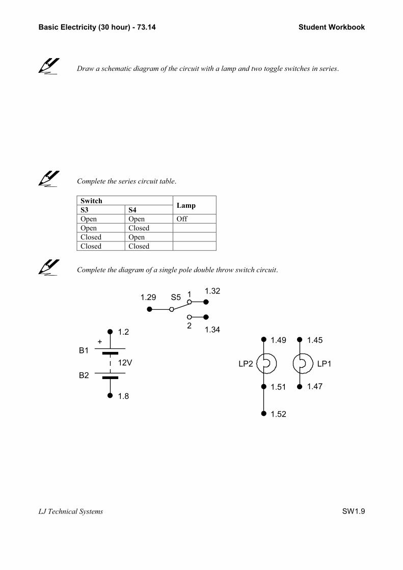
Draw a schematic diagram of the circuit with a lamp and two toggle switches in series.
Complete the series circuit table.
SwitchS3 S4 Lamp
Open Open OffOpen ClosedClosed OpenClosed Closed
Complete the diagram of a single pole double throw switch circuit.
1.2
12V
1.8
B1
B2
1.52
1.51
1.49 1.45
1.47
LP2 LP1
1.29 S5 1
2 1.34
1.32
+

Basic Electricity (30 hour) - 73.14 Student Workbook
LJ Technical Systems SW1.10
Copy the two way house lighting circuit into the space provided.
Assignment 11 Switches in Parallel
Complete the diagram to show the switches connected in parallel.
1.3 _ 1.4
1.1 + 1.2
+ -
B16V
BATTERIES LAMPS
1.19
1.21
S1
SWITCHES
1.15
S2
S31.22
1.16
1.201.17 1.18
1.13 1.14
1.23 1.24
PUSH TO BREAK
CLOSED
1.47 1.48
1.49 1.50
1.51 1.52
1.45 1.46
1.7 _ 1.8
1.5 + 1.6
+ -
B26V
LP1
LP2
OPEN 1.53 1.54
1.55 1.56
LP3
PUSH TO MAKE
1.25S4
1.26 1.27 1.28
CLOSED
OPEN
1.29S5
1.30
1.31 1.321
2
1.33 1.34
Complete the parallel circuit table.
SwitchS3 S4 Lamp
Open Open OffOpen ClosedClosed OpenClosed Closed
Basic Electricity (30 hour) - 73.14 Student Workbook
LJ Technical Systems SW1.11
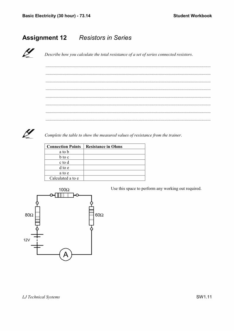
Assignment 12 Resistors in Series
Describe how you calculate the total resistance of a set of series connected resistors.
........................................................................................................................................................
........................................................................................................................................................
........................................................................................................................................................
........................................................................................................................................................
........................................................................................................................................................
........................................................................................................................................................
........................................................................................................................................................
........................................................................................................................................................
Complete the table to show the measured values of resistance from the trainer.
Connection Points Resistance in Ohmsa to bb to cc to dd to ea to e
Calculated a to e
A
12V
100Ω
80Ω 60Ω
Use this space to perform any working out required.

Basic Electricity (30 hour) - 73.14 Student Workbook
LJ Technical Systems SW1.12
Assignment 13 Resistors in Parallel
Write the formula and the example for equal value resistors in parallel in the space provided.
Write the formula and the example for unequal value resistors in parallel in thespace provided.
Use the following space for any calculations you need to make.

Basic Electricity (30 hour) - 73.14 Student Workbook
LJ Technical Systems SW1.13
Assignment 14 Switching with Light
Complete the circuit diagram of the light sensor circuit.
1.3 _ 1.4
1.1 + 1.2
+ -
B16V
BATTERIES BUZZER
1.19
1.21
S1
SWITCHES
1.15
S2
S31.22
1.16
1.201.17 1.18
1.13 1.14
1.23 1.24
PUSH TO BREAK
CLOSED
1.74
1.75
1.76
1.73
1.7 _ 1.8
1.5 + 1.6
+ -
B26V
BZ1
OPEN
PUSH TO MAKE
1.25S4
1.26 1.27 1.28
CLOSED
OPEN
1.29S5
1.30
1.31 1.321
2
1.33 1.34
+
_
LIGHT - ACTIVATED
1.65 1.66
1.63 1.64
1.67 1.68
SWITCH
SENSOR
Complete the circuit diagram of the modified light sensor circuit.
LIGHT - ACTIVATED
1.65 1.66
1.63 1.64
1.67 1.68
SWITCH
SENSOR
LAMPS
1.47 1.48
1.49 1.50
1.51 1.52
1.45 1.46 LP1
LP2
1.53 1.54
1.55 1.56
LP3
1.19
1.21
S1
SWITCHES
1.15
S2
S31.22
1.16
1.201.17 1.18
1.13 1.14
1.23 1.24
PUSH TO BREAK
CLOSED
OPEN
PUSH TO MAKE
1.25S4
1.26 1.27 1.28
CLOSED
OPEN
1.29S5
1.30
1.31 1.321
2
1.33 1.34
1.3 _ 1.4
1.1 + 1.2
+ -
B16V
BATTERIES
1.7 _ 1.8
1.5 + 1.6
+ -
B26V

Basic Electricity (30 hour) - 73.14 Student Workbook
LJ Technical Systems SW1.14
Assignment 15 Heating
Complete the circuit diagram for the home heating system.
HEATER AND THERMOSTAT
1.79 1.80
1.77 1.78
1.81 1.82
1.19
1.21
S1
SWITCHES
1.15
S2
S31.22
1.16
1.201.17 1.18
1.13 1.14
1.23 1.24
PUSH TO BREAK
CLOSED
OPEN
PUSH TO MAKE
1.25S4
1.26 1.27 1.28
CLOSED
OPEN
1.29S5
1.30
1.31 1.321
2
1.33 1.34
1.3 _ 1.4
1.1 + 1.2
+ -
B16V
BATTERIES
1.7 _ 1.8
1.5 + 1.6
+ -
B26V
1.83 1.84
1.85 1.86SENSORHEATER
LAMPS
1.47
1.49
1.51
1.45 LP1
LP2
1.53
1.55
LP3
1.46
1.48
1.50
1.52
1.54
1.56
Complete the table with your results (see how to complete your table if you are unsure how tocomplete it).
Status Time On/Off Duration(seconds)
On 1 startOff 1 start On: Off 1 time – On 1 timeOn 2 start Off: On 2 time – Off 1 timeOff 2 start On: Off 2 time – On 2 timeOn 3 start Off: On 3 time – Off 2 timeOff 3 start On: Off 3 time – On 3 timeOn 4 start Off: On 4 time – Off 3 time
Basic Electricity (30 hour) - 73.14 Student Workbook
LJ Technical Systems SW1.15
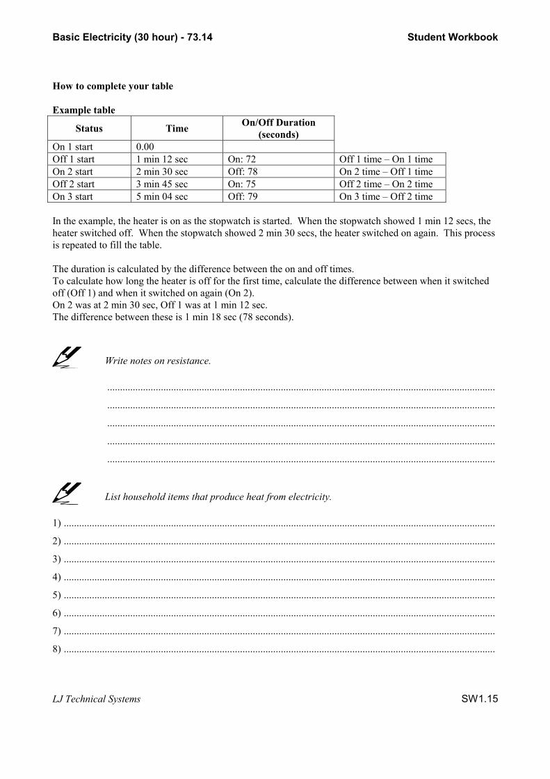
How to complete your table
Example table
Status Time On/Off Duration(seconds)
On 1 start 0.00Off 1 start 1 min 12 sec On: 72 Off 1 time – On 1 timeOn 2 start 2 min 30 sec Off: 78 On 2 time – Off 1 timeOff 2 start 3 min 45 sec On: 75 Off 2 time – On 2 timeOn 3 start 5 min 04 sec Off: 79 On 3 time – Off 2 time
In the example, the heater is on as the stopwatch is started. When the stopwatch showed 1 min 12 secs, theheater switched off. When the stopwatch showed 2 min 30 secs, the heater switched on again. This processis repeated to fill the table.
The duration is calculated by the difference between the on and off times.To calculate how long the heater is off for the first time, calculate the difference between when it switchedoff (Off 1) and when it switched on again (On 2).On 2 was at 2 min 30 sec, Off 1 was at 1 min 12 sec.The difference between these is 1 min 18 sec (78 seconds).
Write notes on resistance.
........................................................................................................................................................
........................................................................................................................................................
........................................................................................................................................................
........................................................................................................................................................
........................................................................................................................................................
List household items that produce heat from electricity.
1) .........................................................................................................................................................................
2) .........................................................................................................................................................................
3) .........................................................................................................................................................................
4) .........................................................................................................................................................................
5) .........................................................................................................................................................................
6) .........................................................................................................................................................................
7) .........................................................................................................................................................................
8) .........................................................................................................................................................................
Basic Electricity30 Hour - Part 2Student Workbook
Issue: US140/30/2b-IQ-0402A
Copyright 2004, LJ Technical Systems. No part of thisPublication may be adapted or reproduced in any material form,without the prior written permission of LJ Technical Systems.
Written by: LJ Technical Dept

Basic Electricity (30 hour) - 73.14 Student Workbook
LJ Technical Systems SW2.1
Assignment 16 Conductors and Insulators
Complete the table to show the conductivity of sample materials.
Material Material Type Conductor / InsulatorCopper MetalBrassSteelAluminumNylonPVCAcrylicRubberHardboardSoftwoodHardwoodCeramicFiber Glass
Write a conclusion about the relationship between material and conductivity..........................................................................................................................................................
.........................................................................................................................................................
.........................................................................................................................................................
.........................................................................................................................................................
Complete the table to show if the objects are conductors or insulators and make any notes youfeel are necessary.
Object Conductor or Insulator(Circle one) Notes
Crayon Conductor InsulatorEraser Conductor InsulatorPaper Conductor InsulatorWood block Conductor InsulatorPlastic spoon Conductor InsulatorMetal scissors Conductor InsulatorMetal paper clip Conductor InsulatorWrench Conductor InsulatorGold ring Conductor InsulatorCoin Conductor InsulatorPencil Conductor InsulatorPickle Conductor Insulator

Basic Electricity (30 hour) - 73.14 Student Workbook
LJ Technical Systems SW2.2
Assignment 17 Alternating Current
Complete the table with current readings.
Connection point Current reading (mA)1.59abcde1.58
Draw a graph of current readings.

Basic Electricity (30 hour) - 73.14 Student Workbook
LJ Technical Systems SW2.3
Draw a graph to show alternating current cycles.
-
Assignment 18 Protective Devices 1
Complete the table to show the effect of using fuses in a circuit.
Note: For effect on the lamp, choose between 'stays on', 'goes off' or 'blows up'.For effect on the fuse, choose between 'remains intact' and 'burns out'.
Fuse value Effect on lamp Effect on fuseNo fuse1 amp1.5 amps2 amps3 amps4 amps5 amps7.5 amps10 amps

Basic Electricity (30 hour) - 73.14 Student Workbook
LJ Technical Systems SW2.4
Complete the table to show the effect of using circuit breakers in a circuit.
Note: For effect on the lamp, choose between 'stays on', stays off' or 'blows up'.For effect on the circuit breaker, choose between 'remains on' and 'trips'.
Circuit breaker value Effect on lamp Effect on circuit breakerNo circuit breaker1 amp2 amps5 amps10 amps
Assignment 19 Protective Devices 2
Describe the different types of GFCI.
Receptacle Type........................................................................................................................................................
........................................................................................................................................................
........................................................................................................................................................
........................................................................................................................................................
........................................................................................................................................................
........................................................................................................................................................
........................................................................................................................................................
........................................................................................................................................................
Circuit Breaker Type........................................................................................................................................................
........................................................................................................................................................
........................................................................................................................................................
........................................................................................................................................................
........................................................................................................................................................
........................................................................................................................................................
........................................................................................................................................................
........................................................................................................................................................

Basic Electricity (30 hour) - 73.14 Student Workbook
LJ Technical Systems SW2.5
Portable Type........................................................................................................................................................
........................................................................................................................................................
........................................................................................................................................................
........................................................................................................................................................
........................................................................................................................................................
........................................................................................................................................................
........................................................................................................................................................
........................................................................................................................................................
........................................................................................................................................................
Draw a diagram to show how double insulation works.
Assignment 20 Magnetism
Complete the diagram showing the magnetic field lines round your magnet.
S N

Basic Electricity (30 hour) - 73.14 Student Workbook
LJ Technical Systems SW2.6
Complete the diagram showing the magnetic field lines round your magnet.
S N SN
S N S N
Assignment 21 Electromagnetic Fields
Complete the diagrams to show the magnetic field lines that have been generated roundthe wire.

Basic Electricity (30 hour) - 73.14 Student Workbook
LJ Technical Systems SW2.7
Complete the diagram to show the magnetic field lines around the coil.
Assignment 22 Relays
Write the current measurements in the relay circuit.
Current in the switch part of the circuit = ...................................amps
Current in the motor part of the circuit = .....................................amps
Basic Electricity (30 hour) - 73.14 Student Workbook
LJ Technical Systems SW2.8
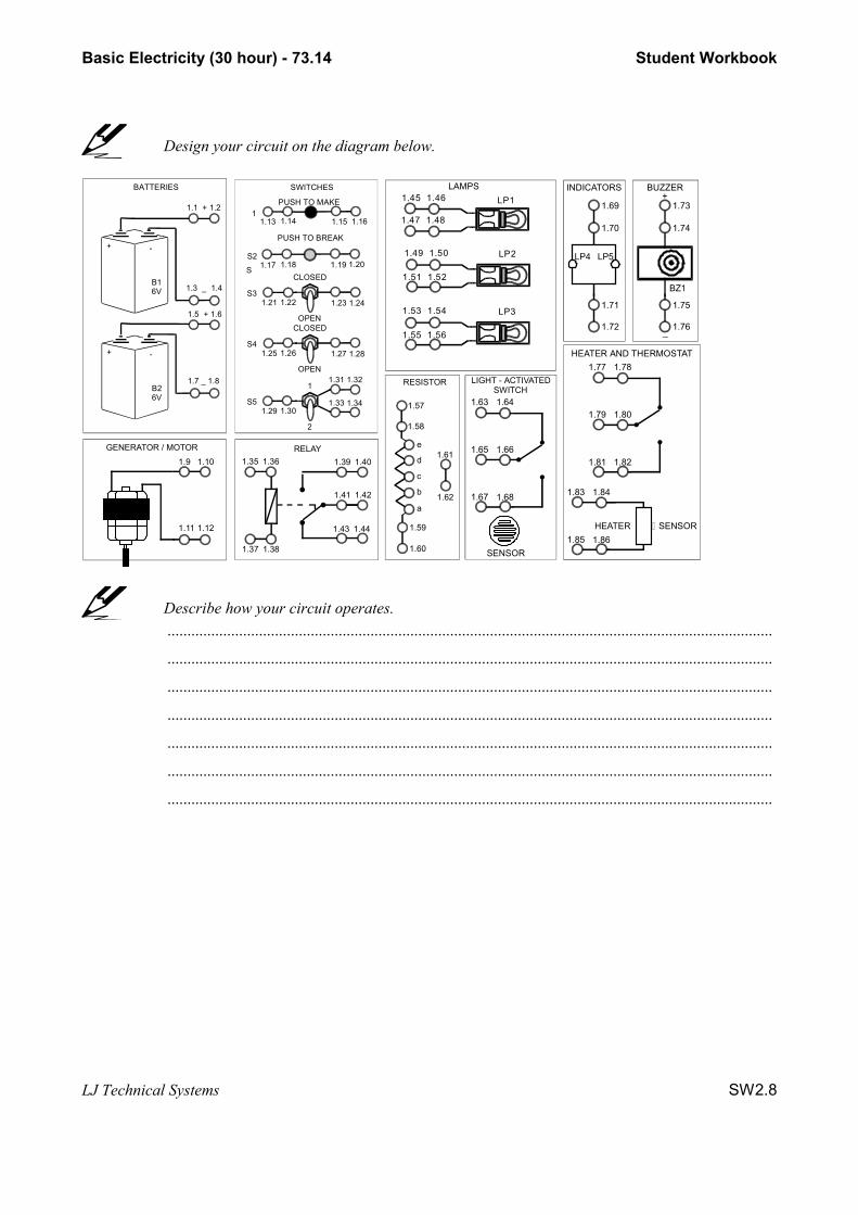
Design your circuit on the diagram below.
1.3 _ 1.4
1.1 + 1.2
+ -
B16V
BATTERIES
1.7 _ 1.8
1.5 + 1.6
+ -
B26V
GENERATOR / MOTOR
1.9 1.10
1.11 1.12
RELAY1.361.35
1.381.37
1.441.43
1.421.41
1.401.39
1.19
1.21
S
1
SWITCHES
1.15
S2
S31.22
1.16
1.201.17 1.18
1.13 1.14
1.23 1.24
PUSH TO BREAK
CLOSED
OPEN
PUSH TO MAKE
1.25S4
1.26 1.27 1.28
CLOSED
OPEN
1.29S5
1.30
1.31 1.321
2
1.33 1.34
RESISTOR
1.58
e
d
1.57
1.59
1.60
1.61
1.62
c
b
a
BUZZER
1.74
1.75
1.76
1.73
BZ1
+
_
1.65 1.66
1.63 1.64
1.67 1.68
SENSOR
LP4 LP5
INDICATORS
1.70
1.71
1.72
1.69
HEATER AND THERMOSTAT
1.79 1.80
1.77 1.78
1.81 1.82
1.83 1.84
1.85 1.86SENSORHEATER
LAMPS
1.47
1.49
1.51
1.45 LP1
LP2
1.53
1.55
LP3
SWITCHLIGHT - ACTIVATED
1.46
1.48
1.50
1.52
1.54
1.56
Describe how your circuit operates.........................................................................................................................................................
........................................................................................................................................................
........................................................................................................................................................
........................................................................................................................................................
........................................................................................................................................................
........................................................................................................................................................
........................................................................................................................................................

Basic Electricity (30 hour) - 73.14 Student Workbook
LJ Technical Systems SW2.9
Assignment 23 Uses of Electromagnets
Complete the table to show how much mass the electromagnet can support.
Number of turns of coil Masses lifted using 1 battery pack Masses lifted using 2 battery packs02507501000
Label the diagram of the speaker.
Label the diagram of the maglev track.

Basic Electricity (30 hour) - 73.14 Student Workbook
LJ Technical Systems SW2.10
Label the diagram of the television tube.
Assignment 24 The Electric Motor
Show the points of Fleming's Right Hand Rule.
Complete the table with your current measurements in the appropriate columns.
Test Position Motor Stationary Current (A) Motor Rotating Current (A)abcde

Basic Electricity (30 hour) - 73.14 Student Workbook
LJ Technical Systems SW2.11
Draw a schematic diagram of the desk fan circuit.
Assignment 25 Electric Generators
Write down the generator principle.........................................................................................................................................................
........................................................................................................................................................
........................................................................................................................................................
Complete the circuits around the magnets to show electrical current being produced.

Basic Electricity (30 hour) - 73.14 Student Workbook
LJ Technical Systems SW2.12
Draw a diagram to show one method of producing electricity that includes the use ofa generator.
Assignment 26 Transformers
Draw a diagram of a step-up transformer and a step-down transformer.
Step-up transformer Step-down transformer
Draw a diagram of one particular electricity production technique that involves the use ofa transformer.
Basic Electricity (30 hour) - 73.14 Student Workbook
LJ Technical Systems SW2.13
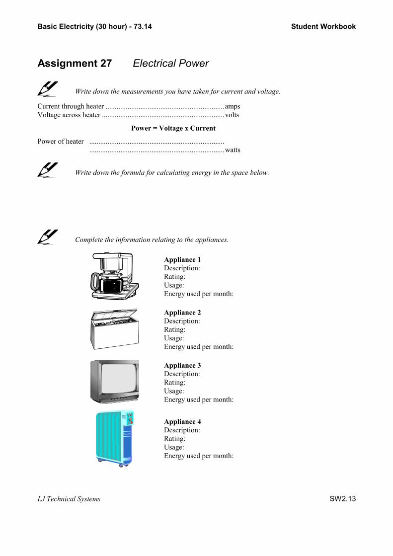
Assignment 27 Electrical Power
Write down the measurements you have taken for current and voltage.
Current through heater .................................................................ampsVoltage across heater ...................................................................volts
Power = Voltage x Current
Power of heater ....................................................................................................................................................watts
Write down the formula for calculating energy in the space below.
Complete the information relating to the appliances.
Appliance 1Description:Rating:Usage:Energy used per month:
Appliance 2Description:Rating:Usage:Energy used per month:
Appliance 3Description:Rating:Usage:Energy used per month:
Appliance 4Description:Rating:Usage:Energy used per month:

Basic Electricity (30 hour) - 73.14 Student Workbook
LJ Technical Systems SW2.14
Assignment 28 Paying for Electricity
Complete the dial meter diagram with the reading 23695 as shown in the example in yourassignment guide.
0 98
765
43
210 1
2
345
67
890 9
8
765
43
210 1
2
345
67
89 0 1
2
345
67
89
Complete the dial meter diagram with the reading 37204.
0 98
765
43
210 1
2
345
67
890 9
8
765
43
210 1
2
345
67
89 0 1
2
345
67
89
Use the following space for any calculations you need to make.

Basic Electricity (30 hour) - 73.14 Student Workbook
LJ Technical Systems SW2.15
Write down the tips for saving energy.
1) ...................................................................................................................................................................
...................................................................................................................................................................
2) ...................................................................................................................................................................
...................................................................................................................................................................
3) ...................................................................................................................................................................
...................................................................................................................................................................
4) ...................................................................................................................................................................
...................................................................................................................................................................
5) ...................................................................................................................................................................
...................................................................................................................................................................
6) ...................................................................................................................................................................
...................................................................................................................................................................
7) ...................................................................................................................................................................
...................................................................................................................................................................
8) ...................................................................................................................................................................
...................................................................................................................................................................
9) ...................................................................................................................................................................
...................................................................................................................................................................
Complete the table to show the monthly average kWh usage.
Appliance Wattage(typical)
Hours of use(monthly average)
kWh(monthly average)
Air conditioner (6000 BTU) 750 720Clothes dryer 5000 25Clothes washer 500 40Computer 200 160Hair dryer 1000 10Kettle 1500 18Television 200 390Video recorder 40 200Water heater 3800 130

Basic Electricity (30 hour) - 73.14 Student Workbook
LJ Technical Systems SW2.16
Assignment 29 Problem Solving, Part 1
Use the following layout to design your circuit for the problem solving exercise.
1.3 _ 1.4
1.1 + 1.2
+ -
B16V
BATTERIES
1.7 _ 1.8
1.5 + 1.6
+ -
B26V
GENERATOR / MOTOR
1.9 1.10
1.11 1.12
RELAY1.361.35
1.381.37
1.441.43
1.421.41
1.401.39
1.19
1.21
S
1
SWITCHES
1.15
S2
S31.22
1.16
1.201.17 1.18
1.13 1.14
1.23 1.24
PUSH TO BREAK
CLOSED
OPEN
PUSH TO MAKE
1.25S4
1.26 1.27 1.28
CLOSED
OPEN
1.29S5
1.30
1.31 1.321
2
1.33 1.34
RESISTOR
1.58
e
d
1.57
1.59
1.60
1.61
1.62
c
b
a
BUZZER
1.74
1.75
1.76
1.73
BZ1
+
_
1.65 1.66
1.63 1.64
1.67 1.68
SENSOR
LP4 LP5
INDICATORS
1.70
1.71
1.72
1.69
HEATER AND THERMOSTAT
1.79 1.80
1.77 1.78
1.81 1.82
1.83 1.84
1.85 1.86SENSORHEATER
LAMPS
1.47
1.49
1.51
1.45 LP1
LP2
1.53
1.55
LP3
SWITCHLIGHT - ACTIVATED
1.46
1.48
1.50
1.52
1.54
1.56
Describe how your circuit will operate........................................................................................................................................
.......................................................................................................................................
.......................................................................................................................................
.......................................................................................................................................
.......................................................................................................................................
.......................................................................................................................................
.......................................................................................................................................
.......................................................................................................................................
.......................................................................................................................................
.......................................................................................................................................

Basic Electricity (30 hour) - 73.14 Student Workbook
LJ Technical Systems SW2.17
Assignment 30 Problem Solving, Part 2
Make any necessary notes on the testing and evaluation of your circuit........................................................................................................................................
.......................................................................................................................................
.......................................................................................................................................
.......................................................................................................................................
.......................................................................................................................................
.......................................................................................................................................
.......................................................................................................................................
.......................................................................................................................................
.......................................................................................................................................
.......................................................................................................................................
Use the following layout to design your modified circuit for the problem solving exercise.
1.3 _ 1.4
1.1 + 1.2
+ -
B16V
BATTERIES
1.7 _ 1.8
1.5 + 1.6
+ -
B26V
GENERATOR / MOTOR
1.9 1.10
1.11 1.12
RELAY1.361.35
1.381.37
1.441.43
1.421.41
1.401.39
1.19
1.21
S
1
SWITCHES
1.15
S2
S31.22
1.16
1.201.17 1.18
1.13 1.14
1.23 1.24
PUSH TO BREAK
CLOSED
OPEN
PUSH TO MAKE
1.25S4
1.26 1.27 1.28
CLOSED
OPEN
1.29S5
1.30
1.31 1.321
2
1.33 1.34
RESISTOR
1.58
e
d
1.57
1.59
1.60
1.61
1.62
c
b
a
BUZZER
1.74
1.75
1.76
1.73
BZ1
+
_
1.65 1.66
1.63 1.64
1.67 1.68
SENSOR
LP4 LP5
INDICATORS
1.70
1.71
1.72
1.69
HEATER AND THERMOSTAT
1.79 1.80
1.77 1.78
1.81 1.82
1.83 1.84
1.85 1.86SENSORHEATER
LAMPS
1.47
1.49
1.51
1.45 LP1
LP2
1.53
1.55
LP3
SWITCHLIGHT - ACTIVATED
1.46
1.48
1.50
1.52
1.54
1.56
Related Documents