ELSEVIER Advances in Engineering Sqfrware 28 (1997) 151-164 ~0 1997 Elsevier Science Limited Printed in Great Britain. All rights reserved PII:SO965-99780(96)00050-6 O965-9978197/$17.00 An assessment of data formats for layered manufacturing* Vinod Kumar & Debasish Dutta Dept. of Mechanical Engineering, University qf Michigan, Ann Arbor, MI 48109-2125, USA (Received for publication 14 October 1996) Layered manufacturing (LM) is an emerging technology for fabricating parts, layer by layer. This technique offers several advantages over conventional manufacturing. The data representation and exchange issues in LM are crucial, and currently the STL format is used as an industry standard. In this paper, we consider 3-D and slice data formats in LM and analyse their strengths and weaknesses. We perform an in-depth analysis of the STL format and comment on the perceived need for its replacement. We also propose metrics for the evaluation of the 3-D and slice formats and compare them. The study reported in this paper can provide guidelines for the development of new representations and formats for use in LM. 8 1997 Elsevier Science Limited. All rights reserved. 1 INTRODUCTION Product data representation and their exchange in CAD/CAM is a critical issue which has received wide attention. With the advent of new manufacturing technologies, data representation and exchange issues have to be reviewed and possibly new protocols established. In this paper, WC consider the above issues in the context of Layered manufacturing (LM). By LM, we refer to the host of manufacturing technologies in which physical parts are ‘built’ layer by layer; we discuss further in Section 2. The initial application of this fabrication tl:chnique was to generate prototypes of parts quickly for design verification. Hence, the LM techniques are also referred to as Rapid prototyping. Layered manufacturing is a fundamentally different method for fabricating a part. The outer (nominal) geometry of the part and interior material distribution is simultaneously realized in LM. All LM technologies are computer-based and require the CAD model of the part that is to be manufactured. As shown in Fig. 1, almost all CAD models have to be converted to the STL format prior to fabrication by LM. Currently, STL serves as a representation as well as a format for LM applications. There is a growing dissatisfaction among LM users about this role of STL and its benefits. The primary focus of this papar is a critical examination of this issue. *Financial support received from the Office of Naval Research grants NOOO14-94-1-0022 and NOOO14-95-1-0767 is gratefully acknowledged. As will be elaborated in later sections, the STL has become an industry standard by default. Our analysis indicates the need for the development of alternatives to STL. In this paper, we provide a survey of all data formats that have been proposed for use in LM. The study reported in this paper can form the basis for the design and development of alternatives to STL. Finally, we identify properties that are desirable in such an STL alternative. In Section 2, we discuss briefly the various steps involved in the LM process. The 3-D data representing the physical object is the input to the LM process, which is then converted to the STL format. In Section 3, we describe in detail the STL format, its advantages and disadvantages, and present some alternate data formats that have been proposed. In Section 4, we present various proposed slice formats for which there exist no industry standard. We present in Section 5 some formats that can store both the 3-D data and the slices. Section 6 contains the comparisons of these formats (both 3-D and slice). Finally, we summarize in Section 7. In this paper, the main emphasis is on STL and slice formats and their transfer methods. While Section 2.2 provides a brief description of the sources of 3-D input data in LM, a detailed analysis of their representation issues is beyond the scope of this paper. 1.1 Terminology Here, we describe our usage of terminology in this paper: 151

Welcome message from author
This document is posted to help you gain knowledge. Please leave a comment to let me know what you think about it! Share it to your friends and learn new things together.
Transcript
ELSEVIER
Advances in Engineering Sqfrware 28 (1997) 151-164 ~0 1997 Elsevier Science Limited
Printed in Great Britain. All rights reserved PII:SO965-99780(96)00050-6 O965-9978197/$17.00
An assessment of data formats for layered manufacturing*
Vinod Kumar & Debasish Dutta Dept. of Mechanical Engineering, University qf Michigan, Ann Arbor, MI 48109-2125, USA
(Received for publication 14 October 1996)
Layered manufacturing (LM) is an emerging technology for fabricating parts, layer by layer. This technique offers several advantages over conventional manufacturing. The data representation and exchange issues in LM are crucial, and currently the STL format is used as an industry standard. In this paper, we consider 3-D and slice data formats in LM and analyse their strengths and weaknesses. We perform an in-depth analysis of the STL format and comment on the perceived need for its replacement. We also propose metrics for the evaluation of the 3-D and slice formats and compare them. The study reported in this paper can provide guidelines for the development of new representations and formats for use in LM. 8 1997 Elsevier Science Limited. All rights reserved.
1 INTRODUCTION
Product data representation and their exchange in CAD/CAM is a critical issue which has received wide attention. With the advent of new manufacturing technologies, data representation and exchange issues have to be reviewed and possibly new protocols established. In this paper, WC consider the above issues in the context of Layered manufacturing (LM). By LM, we refer to the host of manufacturing technologies in which physical parts are ‘built’ layer by layer; we discuss further in Section 2. The initial application of this fabrication tl:chnique was to generate prototypes of parts quickly for design verification. Hence, the LM techniques are also referred to as Rapid prototyping.
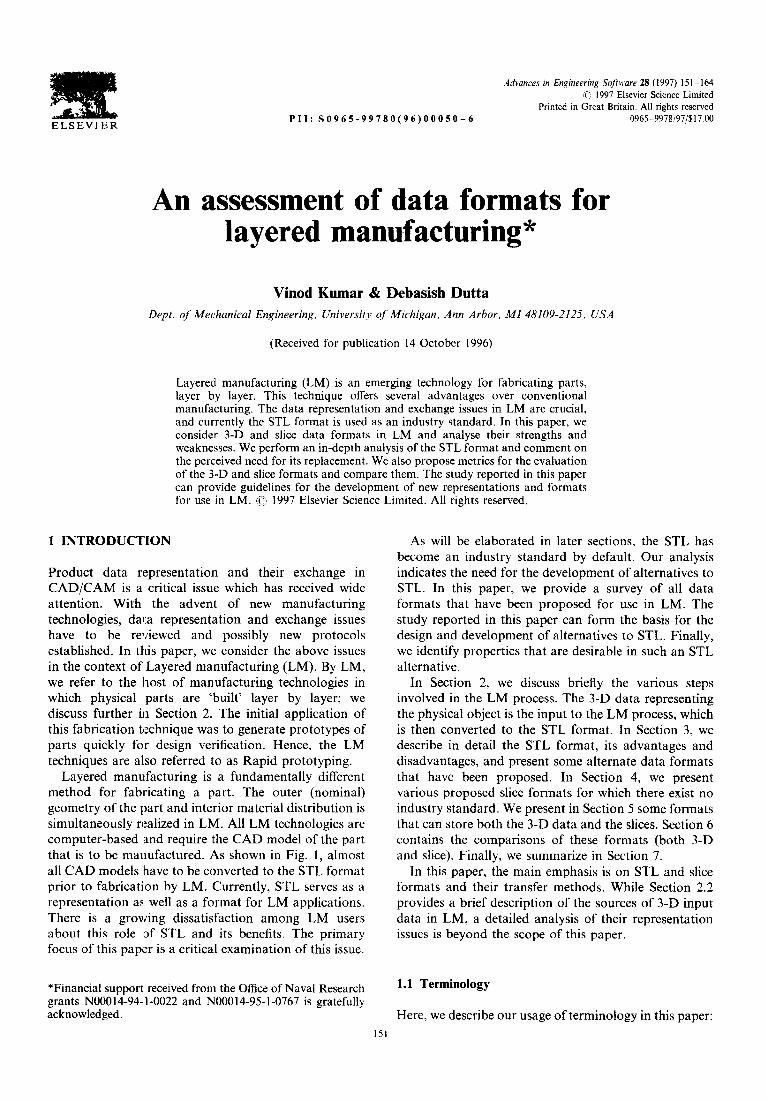
Layered manufacturing is a fundamentally different method for fabricating a part. The outer (nominal) geometry of the part and interior material distribution is simultaneously realized in LM. All LM technologies are computer-based and require the CAD model of the part that is to be manufactured. As shown in Fig. 1, almost all CAD models have to be converted to the STL format prior to fabrication by LM. Currently, STL serves as a representation as well as a format for LM applications. There is a growing dissatisfaction among LM users about this role of STL and its benefits. The primary focus of this papar is a critical examination of this issue.
*Financial support received from the Office of Naval Research grants NOOO14-94-1-0022 and NOOO14-95-1-0767 is gratefully acknowledged.
As will be elaborated in later sections, the STL has become an industry standard by default. Our analysis indicates the need for the development of alternatives to STL. In this paper, we provide a survey of all data formats that have been proposed for use in LM. The study reported in this paper can form the basis for the design and development of alternatives to STL. Finally, we identify properties that are desirable in such an STL alternative.
In Section 2, we discuss briefly the various steps involved in the LM process. The 3-D data representing the physical object is the input to the LM process, which is then converted to the STL format. In Section 3, we describe in detail the STL format, its advantages and disadvantages, and present some alternate data formats that have been proposed. In Section 4, we present various proposed slice formats for which there exist no industry standard. We present in Section 5 some formats that can store both the 3-D data and the slices. Section 6 contains the comparisons of these formats (both 3-D and slice). Finally, we summarize in Section 7.
In this paper, the main emphasis is on STL and slice formats and their transfer methods. While Section 2.2 provides a brief description of the sources of 3-D input data in LM, a detailed analysis of their representation issues is beyond the scope of this paper.
1.1 Terminology
Here, we describe our usage of terminology in this paper: 151
152 V. Kumar, D. Dutta
Fig. 1. STL as a link to the LM process.
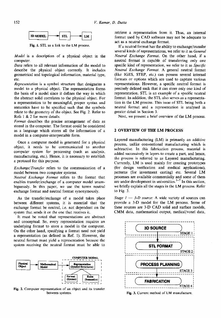
Model is a description of a physical object in the computer. Data refers to all relevant information of the model to describe the physical object correctly. It includes geometrical and topological information, material type, etc. Representation is a symbol structure that designates a model to a physical object. The representation forms the basis of a model since it defines the way in which the abstract solid correlates to the physical object. For a representation to be meaningful, proper syntax and semantics have to be specified such that the symbols relate to the geometry of the object. See Fig. 2. Refer to Refs 1 & 2 for more details. Format describes the precise arrangement of data as stored in the computer. The format could be considered as a language which stores all the information of a model in a computer-interpretable form.
Once a computer model is generated for a physical object, it needs to be communicated to another computer system for processing (such as analysis, manufacturing, etc.). Hence, it is necessary to establish a protocol for this purpose.
Exchange/Transfer refers to the communication of a model between two computer systems. Neutral Exchange Format refers to the format that enables transfer/exchange of a computer model unam- biguously. In this paper, we use the terms neutral exchange format and neutral format synonymously.
As the transfer/exchange of a model takes place between different systems, it is essential that the exchange format be neutral, i.e. not dependent on the system that sends it or the one that receives it.
It must be noted that representations are abstract and conceptual. So, every representation requires an underlying format to store a model in the computer. On the other hand, specifying a format need not yield a representation (as defined in Ref. 1). However, the neutral format must yield a representation because the system receiving the neutral format must be able to
COMPUTER MODEL
i”‘H~~~~~~ ]
Fig. 2. Computer representation of an object and its transfer between systems.
retrieve a representation from it. Thus, an internal format used by CAD software may not be adequate to act as a neutral exchange format.
If a neutral format has the ability to exchange/transfer several kinds of representations, we refer to it as General Neutral Exchange Format. On the other hand, if a neutral format is capable of transferring only one specific kind of representation, we refer to it as Specific Neutral Exchange Format. A general neutral format (like IGES, STEP, etc.) can possess several internal formats or options which are used to capture various representations. However, a specific neutral format is precisely defined such that it can store only one kind of representation. STL is an example of a specific neutral format. In addition, the STL also serves as a representa- tion in the LM process. This issue of STL being both a neutral format and a representation is analysed in greater detail in Section 3.
Next, we present a brief overview of the LM process.
2 OVERVIEW OF THE LM PROCESS
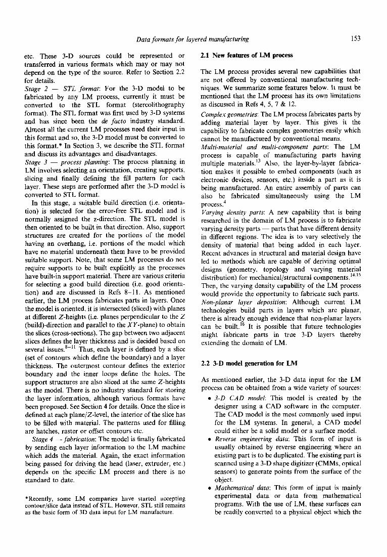
Layered manufacturing (LM) is primarily an additive process, unlike conventional manufacturing which is subtractive. In this fabrication process, material is added successively in layers to create a part, and hence, the process is referred to as Layered manufacturing. Currently, LM is used mainly for creating prototypes (for design verification and medical applications), patterns (for investment casting) etc. Several LM processes are available commercially and some of them are under development in universities.3-7 In this section, we briefly explain all the stages in the LM process. Refer to Fig. 3.
Stage I - 3-D source: A wide variety of sources can provide a 3-D model for the LM process. Some of these sources are 3-D CAD solid and surface models, CMM data, mathematical output, medical/voxel data,
,_________________------------------ 1 I 1 I 0 3D SOURCE I I 1 0 I STAGE 1 f ---------------- _______________-_, ---------------- I -_--_____________, I 8 I I I I STL FORMAT 1 8 ____________--______---------------, r---------------‘.------------------, 0 I , 1 I 1 I I I I PROCESS PLANNIN I 1 I I I_______-------_ STAGE 3 ’ -----------------J ,________---_--- --_______________. I 1 I 1 ! FABRICATION I 1 ~______-----------__~~~~~~~~-~~~~--,
Fig. 3. Current method of LM manufacture.
Data formats for layered manufacturing 153
etc. These 3-D sources could be represented or transferred in various formats which may or may not depend on the type of the source. Refer to Section 2.2 for details. Stage 2 - STI: format: For the 3-D model to be fabricated by any LM process, currently it must be converted to the STL format (stereolithography format). The STL format was first used by 3-D systems and has since been the de facto industry standard. Almost all the cu.rrent LM processes need their input in this format and so, the 3-D model must be converted to this format.* In Section 3, we describe the STL format and discuss its advantages and disadvantages. Stage 3 - process planning: The process planning in LM involves selecting an orientation, creating supports, slicing and finally defining the fill pattern for each layer. These steps are performed after the 3-D model is converted to STL format.
In this stage, .a suitable build direction (i.e. orienta- tion) is selected for the error-free STL model and is normally assigned the z-direction. The STL model is then oriented to be built in that direction. Also, support structures are created for the portions of the model having an overhang, i.e. portions of the model which have no material underneath them have to be provided suitable support. Note, that some LM processes do not require supports to be built explicitly as the processes have built-in support material. There are various criteria for selecting a good build direction (i.e. good orienta- tion) and are discussed in Refs 8-l 1. As mentioned earlier, the LM process fabricates parts in layers. Once the model is oriented, it is intersected (sliced) with planes at different Z-he:ights (i.e. planes perpendicular to the Z (build)-direction and parallel to the XY-plane) to obtain the slices (cross-sections). The gap between two adjacent slices defines the layer thickness and is decided based on several issues.*-” Thus, each layer is defined by a slice (set of contours ,which define the boundary) and a layer thickness. The outermost contour defines the exterior boundary and the inner loops define the holes. The support structures are also sliced at the same Z-heights as the model. There is no industry standard for storing the layer information, although various formats have been proposed. Slee Section 4 for details. Once the slice is defined at each plane/Z-level, the interior of the slice has to be filled with material. The patterns used for filling are hatches, raster or offset contours etc.
Stage 4 -fabrication: The model is finally fabricated by sending each layer information to the LM machine which adds the material. Again, the exact information being passed for driving the head (laser, extruder, etc.) depends on the specific LM process and there is no standard to date.
*Recently, some LM companies have started accepting contour/slice data instead of STL. However, STL still remains as the basic form of 3D data input for LM manufacture.
2.1 New features of LM process
The LM process provides several new capabilities that are not offered by conventional manufacturing tech- niques. We summarize some features below. It must be mentioned that the LM process has its own limitations as discussed in Refs 4, 5, 7 8~ 12. Complex geometries: The LM process fabricates parts by adding material layer by layer. This gives it the capability to fabricate complex geometries easily which cannot be manufactured by conventional means. Multi-material and multi-component parts: The LM process is capable of manufacturing parts having multiple materials.13 Also, the layer-by-layer fabrica- tion makes it possible to embed components (such as electronic devices, sensors, etc.) inside a part as it is being manufactured. An entire assembly of parts can also be fabricated simultaneously using the LM process.4 Varying density parts: A new capability that is being researched in the domain of LM process is to fabricate varying density parts - parts that have different density in different regions. The idea is to vary selectively the density of material that being added in each layer. Recent advances in structural and material design have led to methods which are capable of deriving optimal designs (geometry, topology and varying material distribution) for mechanical/structural components.‘4’15 Then, the varying density capability of the LM process would provide the opportunity to fabricate such parts. Non-planar layer deposition: Although current LM technologies build parts in layers which are planar, there is already enough evidence that non-planar layers can be built.16 It is possible that future technologies might fabricate parts in true 3-D layers thereby extending the domain of LM.
2.2 3-D model generation for LM
As mentioned earlier, the 3-D data input for the LM process can be obtained from a wide variety of sources:
3-D CAD model: This model is created by the designer using a CAD software in the computer. The CAD model is the most commonly used input for the LM systems. In general, a CAD model could either be a solid model or a surface model. Reverse engineering data: This form of input is usually obtained by reverse engineering where an existing part is to be duplicated. The existing part is scanned using a 3-D shape digitizer (CMMs, optical sensors) to generate points from the surface of the object. Mathematical data: This form of input is mainly experimental data or data from mathematical programs. With the use of LM, these surfaces can be readily converted to a physical object which the
V. Kumar, D. Dutta 154
0
a
user can hold and understand the geometry/details of the solution. Medicallvoxel data: Medical data are obtained by scanning parts of the human body; the only difference being the data is truly three-dimensional, i.e. data is obtained both from the exterior and the interior of the object. The most commonly used methods for getting these data are CT (computed tomography) and NMR (nuclear mag- netic resonance). Layered data: The 3-D data may also be obtained as layers/contours/slices, i.e. cross-sections of the shape at different levels. Examples include topographic data, geophysical data,4 engineering data,17 etc.
A detailed review of these sources and the representation issues of various 3-D models (i.e. Stage 1 in Fig. 3) are discussed in Refs 2, 4, 5 & 18. Depending on the 3-D model/data, they can be converted to STL or directly to slices/contours.
3 3-D MODEL TRANSFER FOR LM
Any 3-D model developed has to be transferred from the designer to the manufacturer. This step, referred to as Data Transfer/Exchange, plays an important role in proper fabrication of a part. The model must not only be transferred correctly and efficiently, but also needs to be inspected and manipulated at either ends of the communication line. For each data transfer, a data translator or a data converter is required that takes in the input and transfers or converts it to the desired output. Note that conversion involves a change in the representation of the model whereas, translation does not. As the LM process relies heavily on data representation, conversion and manipulation, this step becomes even more critical for accurate fabrication.19,20
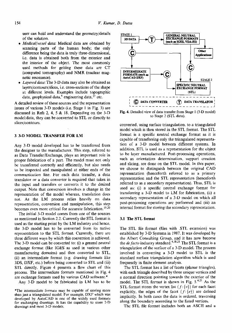
The initial 3-D model comes from one of the sources as mentioned in Section 2.2. Currently the STL format is used as the starting point by the LM industry and hence, the 3-D model has to be converted from its native representation to the STL format. Currently, there are three different ways by which this conversion is achieved. The 3-D model can be converted to: (i) a general neutral exchange format (like IGES as used in various other manufacturing domains) and then converted to STL, (ii) an intermediate format (e.g. drawing formats like 3DS, DXF, etc.) before being converted to STL and (iii) STL directly. Figure 4 presents a flow chart of this process. The intermediate formats mentioned in Fig. 4 are exchange formats used by various CAD software.*
Any 3-D model to be fabricated in LM has to be
*The intermediate formats may be capable of storing more than just a triangulated model. For example, DXF which was developed by AutoCAD is one of the widely used formats for exchanging drawings. It has the capability to store 2-D drawings and most 3-D models.
STAGE 1 GENERAL NEUTRAL 3D DATA EXCFIANGE FORMATS
(such as IGJlS, VDA-FS) I 1
r------------------------~
IO DATA CONVERTER 0 DATA TRANSLATOR ]
L---------------_-_------J
Fig. 4. Detailed view of data transfer from Stage 1 (3-D model) to Stage 2 (STL data).
converted, using surface triangulation, to a triangulated model which is then stored in the STL format. The STL format is a specific neutral exchange format as it is capable of transferring only the triangulated representa- tion of a 3-D model between different systems. In addition, STL is used as a representation for the object to be layer manufactured. Post-processing operations, such as orientation determination, support creation and slicing, are done on the STL model. In this paper, we choose to distinguish between the original CAD representation (henceforth referred to as a primary representation and the STL representation (henceforth referred to as a secondary representation). Thus, STL is used as: (i) a specific neutral exchange format for transferring a 3-D model to LM for fabrication, (ii) a secondary representation of a 3-D model on which all post-processing operations are performed and (iii) an internal format for storing the secondary representation.
3.1 The STL format
The STL file format (files with .STL extension) was established by 3-D Systems in 1987. It was developed by the Albert Consulting Group, and it has now become the de facto industry standard.4’18’21 The STL format is a triangulation of the surface of a 3-D model. The process involved in converting a 3-D model to STL is the standard surface triangulation algorithm which is used frequently in finite element analysis.
The STL format has a list of facets (planar triangles), with each triangle described by three unique vertices and a normal direction pointing towards the exterior of the model. The STL format is shown in Fig. 5.4>2’ As the STL format stores the vertex list (f: {u}) for each facet explicitly, the edges of the facet (f: {e}) are defined implicitly. In both cases the data is ordered, traversing along the boundary according to the listed vertices.
The STL file format includes both an ASCII and a
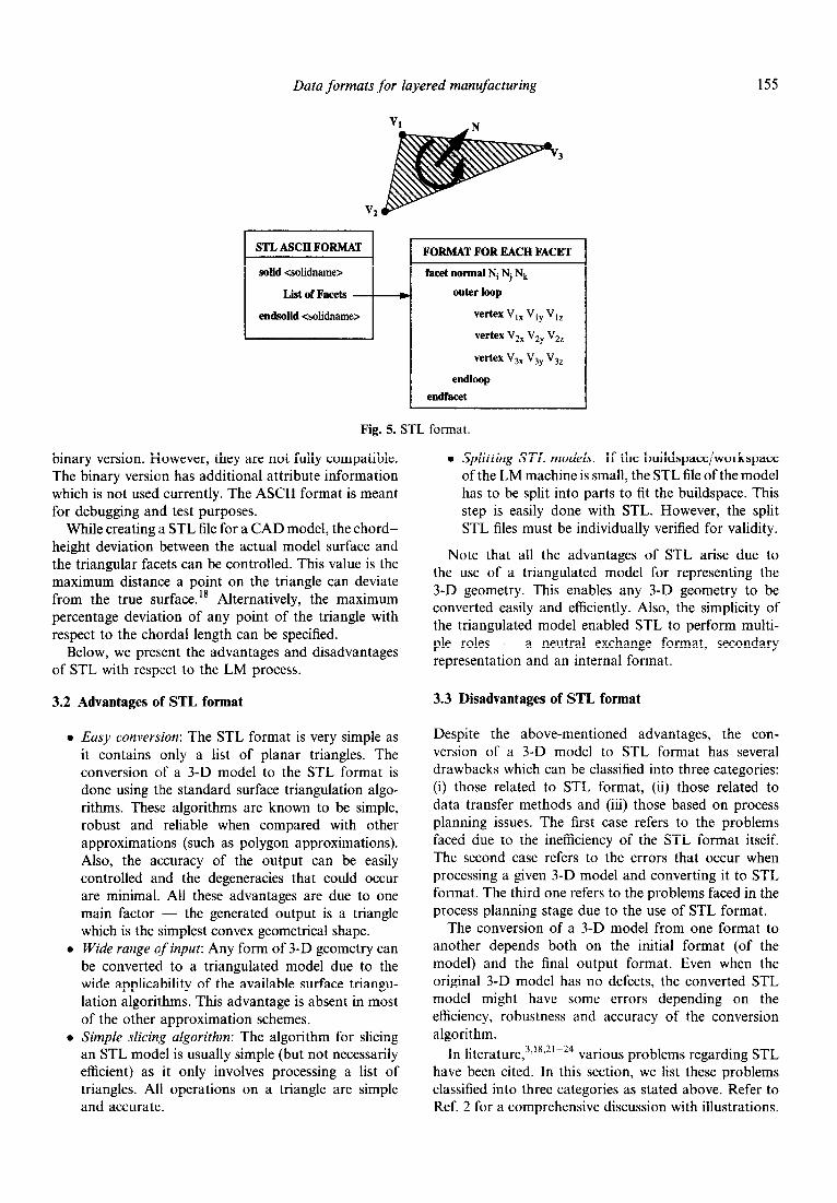
Data formats for layered manufacturing 155
STL ASCII FORMAT
solid <solidnames
List of Facets
endsolid <solidname>
FORMAT FOR EACH FACET
facet normal Ni Nj N,
w outer loop vertex V,, V,, V,,
vertex V,, Vzy Vzz
ve*x V3, V3, V3,
endloop endfacet
Fig. 5. STL format.
binary version. However, they are not fully compatible. The binary version has additional attribute information which is not used currently. The ASCII format is meant for debugging arrd test purposes.
While creating a STL file for a CAD model, the chord- height deviation between the actual model surface and the triangular facets can be controlled. This value is the maximum distance a point on the triangle can deviate from the true surface.‘* Alternatively, the maximum percentage deviation of any point of the triangle with respect to the chordal length can be specified.
Below, we present the advantages and disadvantages of STL with respect to the LM process.
3.2 Advantages of STL format
l Easy conversion: The STL format is very simple as it contains only a list of planar triangles. The conversion of a 3-D model to the STL format is done using the standard surface triangulation algo- rithms. Thes’e algorithms are known to be simple, robust and reliable when compared with other approximations (such as polygon approximations). Also, the accuracy of the output can be easily controlled and the degeneracies that could occur are minimal. All these advantages are due to one main factor - the generated output is a triangle which is the simplest convex geometrical shape.
l Wide range qf input: Any form of 3-D geometry can be converted to a triangulated model due to the wide applicability of the available surface triangu- lation algorithms. This advantage is absent in most of the other approximation schemes.
l Simple slicing algorithm: The algorithm for slicing an STL modI: is usually simple (but not necessarily efficient) as it only involves processing a list of triangles. All operations on a triangle are simple and accurate.
l Splitting STL models: If the buildspace/workspace of the LM machine is small, the STL file of the model has to be split into parts to fit the buildspace. This step is easily done with STL. However, the split STL files must be individually verified for validity.
Note that all the advantages of STL arise due to the use of a triangulated model for representing the 3-D geometry. This enables any 3-D geometry to be converted easily and efficiently. Also, the simplicity of the triangulated model enabled STL to perform multi- ple roles - a neutral exchange format, secondary representation and an internal format.
3.3 Disadvantages of STL format
Despite the above-mentioned advantages, the con- version of a 3-D model to STL format has several drawbacks which can be classified into three categories: (i) those related to STL format, (ii) those related to data transfer methods and (iii) those based on process planning issues. The first case refers to the problems faced ~due to the inefficiency of the STL format itself. The second case refers to the errors that occur when processing a given 3-D model and converting it to STL format. The third one refers to the problems faced in the process planning stage due to the use of STL format.
The conversion of a 3-D model from one format to another depends both on the initial format (of the model) and the final output format. Even when the original 3-D model has no defects, the converted STL model might have some errors depending on the efficiency, robustness and accuracy of the conversion algorithm.
In literature,3.‘8’21-24 various problems regarding STL have been cited. In this section, we list these problems classified into three categories as stated above. Refer to Ref. 2 for a comprehensive discussion with illustrations.
156 V. Kumar, D. Dutta
3.3.1 Problems intrinsic to STL format
l Verbose: STL file is verbose and has redundant data. The storage of facet normal is redundant as this can be obtained from the vertex list of each facet (f:{ } f w in ormation) by accessing them in the specified order. Also, specifying the vertices of each facet (triangle) is not required as each vertex appears in more than one facet. The vertex can be specified once and all facets containing it can reference it. This also solves the problem of having mismatch in the location of identical vertices.
l Approximation: A major problem with STL is in its representation of curved surfaces, which can only be approximated by the triangular facets. A large number of facets can yield high accuracy in approximation, but would result in an extremely large file. A smaller number of facets would create an efficient file but would lack accuracy.
l Truncation: The original CAD model which is represented in double precision is converted to single precision while generating the STL data. Hence, with the absence of topological informa- tion in the STL model, truncation errors become significant (especially when the model is located farther away from the origin).
a Lack of information: The original 3-D model, in general, is complete and could possess useful information regarding geometry, topology and material. By converting it to STL format, only the basic geometry information is stored neglecting other relevant information. Such information could be used in downstream processing (selecting build direction, analyse the model for support creation, etc.) or to verify the solidity of the converted model.
3.3.2 Problems in conversion to STL format
l Gaps: Facets (triangles) of the STL data connect to form a set of closed shells (surfaces) that enclose material. But if any of the facets are missing, then the shell is punctured, having gaps, and so, there is no clear distinction between the inside and the outside. Also, when a STL file with gaps is sliced, it can create open contours in the slices, thereby producing stray vectors in fabrication.
l Inconsistent normals: Facet normals could be flipped (normals pointing towards the inside of the model instead of pointing outwards) and thus be inconsistent with the orientation of other facets.
l Incorrect normals: Facet normals may not be the same as the normal computed from the facet’s vertices.
l Incorrect intersections: Facets may intersect at incorrect locations (apart from their edges), i.e. overlapping facets.
l Internal walls and structures: These could be generated by faulty geometric algorithms while
closing gaps in STL and can cause discontinuities in the solidification of the material. Inconsistencies: An STL file might have inconsistent tolerance values as it was created by appending two different STL files. Also, there may be gaps at the intersection of the two STL models that were appended. Facet degeneracy: Facets may be degenerate, i.e. they do not span finite area and consequently have no normal. There are two kinds of facet degeneracy:
Topological degeneracy: Two or more vertices of a facet coincide. This degeneracy does not affect the geometry or connectivity of remaining facets and so, the facet can be discarded. Geometric degeneracy: All the vertices of a facet are distinct and all edges of the facet are collinear. This geometrically degenerate facet has no normal but it contains implicit topological information on how the neighboring facets are connected, i.e. how two surfaces mate.
3.3.3 Problems in process planning due to STL
b
b
b
3.4
STL repair: Due to the above-listed problems, additional operations/manipulations have to be performed on the STL model to guarantee the correctness of the model. This repair of incorrect STL model is very computationally intensive and is a major drawback of STL. The ease of STL repair depends on the model and sometimes it might be easier to correct the original model or repair the sliced model. The amount of work done in this step could be minimized if the format does not allow any errors to creep in during data transfer. Lackofgeometricltopologicalinformation: Currently, process planning operations (i.e. choosing orien- tation, support creation and slicing, etc.) are performed using the STL format of a 3-D model. A significant amount of user intervention is required. The development of efficient algorithms for automated process planning would require the topological information of the model which is absent in STL. Lack of product/process information: STL does not have the capability to communicate all relevant information regarding a model (such as process related, material, etc.)
Do we need to replace STL?
The STL format that is now an LM industry standard was developed around 1987 for stereolithography, the first LM process. Surface triangulation schemes were already available since they had been developed in the context of FEM in the 1970s. Therefore, we conjecture the STL format was adopted since surface triangulation schemes were available, simple and easy to use. It
Data formats for layered manufacturing 157
enabled the import of 3-D geometries from various commercial systems and eventually became an industry standard. All post-processing algorithms were devel- oped after the adoption of the STL format and hence, used STL as the input to their system.
Despite its disadvantages, STL is simple and easy to use. The initial application of LM was rapid proto- typing, i.e. the quick creation of physical mock-ups for design verification. Surely, approximations of the 3-D model and the use of STL in this context is sufficient and justified. Most importantly, the adoption of STL preceded the development of all process-planning algorithms in LM. Therefore, now STL acts as a standardized input for all the process-planning software. This provides great flexibility to the user. First, it enables the import of any 3-D geometry regardless of the primary representations. Next, it allows the 3-D geometry to be post-processed using any LM software and finally, fabricate it using any LM technology.
It is however crucial that the alternative(s) to STL be chosen judicially. The chosen format should be a specific neutral format such that it retains the unified-input aspect of STL. Also, the conversion from any primary representation of the 3-D geometry to this specific neutral format must be easy. This would allow all post- processing software in LM (current as well as future) to accept any 3-D geometry using a single input.
3.5 Proposed alternatives to STL
We now present alternatives to STL that have been proposed in the literature.
STL, used as a specific neutral format, provides a unzjied-input to the LM process. A data conversion (in the form of surface triangulation) is performed because the STL format stores only the surface triangulation of a 3-D geometry (refer tal Fig. 4). This triangulated model in the STL format (STL model, in short) is a specific representa- tion of the initial model, and acts as a single unified input to all downstream processing that are performed in layered manufacturing. Such a unification cannot be achieved by any general neutral formats such as IGES, STEP, etc., because they store the 3-D geometry in its primary representation. Hence, for the post-processing software that receives the 3-D geometry through IGES or STEP to be widely applicable, it has to accept several different representations as its input. In contrast, the STL format, as a specific neutral format, allows LM post- processing software to accept a single unified input which is a surface triangulation of the 3-D geometry created in any primary representation. This unification of input, that currently exi:sts in the LM process, is an important feature that must be maintained.
3.5.1 STH - Surface Triangles Hinted format Developed by Brock Rooney and Associates, it uses surface triangulation (like STL) with flexible rules for efficient storage of vertex and connection information.4 It is more compact and contains optional structural information on source volumes and surfaces. Hence, the underlying format used here is same as STL but with improved storage capability.
3.5.2 CFL - Cubital Facet List This format represents the model using planar facets which are multi-sided (i.e. polygons) and have multiple holes. The coordinates of the vertices are stored and indexed. The facet descriptions reference the vertices by their indices and not by value. This saves space and also maintains the adjacency relationship (con- nectivity) of the model. The format also has provisions for storing comments similar to IGES. This format also allows the description of a model as a series of slices (contours). CFL was developed by Cubita125>26 to overcome the problems with STL but is not very popular. The advantage of this format is that it contains both geometry and topological information.
3.5.3 RPI format Over the last decade, significant advances have The RPI format27 can represent facet models and CSG
been made in all aspects (hardware, software, materials, primitive models along with the Boolean operations. etc.) of LM technologies. New materials and process The format allows 3-D transformations, multiple capabilities have expanded the application domain of instancing and process parameter specifications. The LM well beyon’d rapid prototyping. Consequently, RPI format is composed of a collection of entities, each severe demands are being made on the formats and of which internally defines the data it contains. Each representation used in LM. For example, the automa- entity has an entity name, record count, schema tion of process :planning algorithms require accurate definition, schema termination symbol and the corre- geometrical, topological and process information. Selec- sponding data. The data is logically subdivided into tive deposition of material for the creation of multi- records which are made of fields. Each record corre- material structures requires material information in the sponds to the definition provided by the schema. Each model. Such requirements cannot be met by the STL field corresponds to one variable type (integer, float, format. Therefore, replacements for STL need to be double, string, Boolean and n-bit binary). In the explored. Furthermore, as described earlier in Section simplest case, this format represents the object using a 3.3, the STL format has several drawbacks, some vertex list and a face list. The vertex list contains the intrinsic to the format and other associated with the list of all vertices of the model along with the transfer to the format. corresponding indices. The face list directly references
158 V. Kumar, D. Dutta
the vertices by their index in the vertex list. The RPI format does allow more complex representations (CSG-based solids) to be stored. So, the RPI format has the flexibility to define and store entities in different ways and can simulate STL, CFL or CSG formats. Also, it can retain all the relevant geometrical, topological and process information.
3.6 Discussion
As mentioned earlier, STL is being used as a neutral exchange format, a secondary representation and an internal format (for storing the secondary representa- tion). This was possible because of the simplicity of the triangulated model. The adoption of a triangulated model (through STL) as the main representation in LM has several advantages. Any 3-D model can be t~angulated and triangulation algorithms are efficient when compared to any other approximation schemes. In particular, polygonization (which is equivalent to a facetted B-Rep) of a 3-D geometry with curved surfaces increases the complexity of the approximation. Tri- angulation is a special case of polygonization with all polygons being triangles. In a general polygonization, the number of degenerate cases (similar to those mentioned in Facet degeneracy of Section 3.3.2) increases drastically depending on the number of sides of a polygon. Controlling the accuracy of the approximation becomes even more difficult. Also, planarity of the polygons {i.e. all vertices of a polygon must lie in a plane) must be ensured. This issue does not arise in the case of triangulation. Thus, the algorithms for polygonization are more complex, and are not as fast, efficient and robust as the triangulation algorithms.
Considering the proposed alternatives to STL, STH improves on the STL by storing more information and using better storage schemes. But, it does not have the capability to store a polyhedral model. Both CFL and RPI can store a polyhedral model (which implies the capability to store a triangulated model). However, as mentioned above, the use of a polyhedral representation of a 3-D geometry has its own drawbacks. The RPI format has the flexibility to define new entities and can store process specifications neither of which is fully available in CFL. Hence, in our opinion, the RPI format would serve better as an exchange format when compared to STH and CFL. In Section 6, we evaluate these formats in detail.
It must be mentioned that formats like DXF, 3DS, etc. (as shown in Fig. 4) were developed by various commercial CAD companies for transfer of data to and from their systems. If these formats are devel- oped further with focus on LM as an application, they could possibly be considered as replacements for STL.
4 SLICE FORMATS FOR LM
After the STL data of a 3-D model is processed, it is sliced to generate the layer information as described in Section 2. In the following, we analyse the role of slice formats in the LM process and present some of the proposed formats that could serve as a standard.
4.1 Existing dice formats
A slice format must enable the storage of all the geometrical data of the layer including the layer thickness. Also, it must have provisions to store process related information, if necessary. Some of the proposed slice formats are mentioned below.
4.1.1 CL1 - Common Layer Interface CL1 is a sliced format proposed by the BRITE/EURAM project2* CL1 is intended as a simple, efficient and unambiguous format for data input to all LM systems. Each layer is represented by its thickness and a set of contours. Contours define the boundaries of the solid material within a layer and are represented by polylines. Each contour should be closed and should not intersect itself or other contours. A hatch is a set of independent straight lines, each defined by a start and an end point. The purpose of hatches and open polylines is to define support and filling structures. The build direction is assumed to be the positive Z-axis and hence the slices are in the planes parallel to the XY plane. Polylines representing internal contours (hence poly- gons) must be clockwise and that of external contours must be counter-clockwise when viewed along the negative Z-axis. There are no non-geometric commands in CLI.
4.1.2 LEAF - Layer E.ychange ASCII Format LEAF was started by Helsinki Institute of Technology also for the BRITE/EURAM project2s and is currently under development in the Fraunhofer Institute, Stuttgart3* The format consists of two sections - the header section and the geometry section. The header section defines the preprocessing instructions, mathe- matical arrangements and technological arrangements. These arrangements are necessary for the geometry section. The preprocessing inst~ctions contain keyword definitions, vendor/machine specific information, etc. The mathematical arrangements define the radix of the number system used, units and ranges of values. The technological arrangements define the structure of hatches and supports. These arrangements can be directly referenced by the geometry section instead of stating it explicitly each time. The geometry section is the layerwise geometrical data of the model. The layer is the main entity used and it contains both geometry data
Data *formats for layered manufacturing 159
and process data. The layer entity can have sub-entities such as region, contour, hatch, support, etc. Each contour is a non-self-intersecting polygon described in terms of 2-D primitives, the polyline and the circular arc. This format is still under development.
4.1.3 HP-GL - Hewlett Packard Graphics Language HP-GL is a 2-D plotting language (like Postscript) from Hewlett Packard and it was developed for plotters/ printers.3’ It is made up of a core set of instructions called the HP-GL kernel and several extensions (which are device specific) such as Technical Graphics Exten- sion, Palette Extension, Dual-context Extension and Digital Extension. The kernel contains most of the instructions and is. divided into five functional groups - configuration and. status, vector, polygon, line and fill attributes, and character. The HP-GL instructions have four components - a mnemonic, parameter(s), separator(s) and a terminator. So, HP-GL is capable of representing an arbitrary 2-D shape filled with any pattern. Hence, it can be used to represent slices and can also be used to drive the LM machine (laser, extruder, etc.) like any plotting device.
4.1.4 SLC~or~nats There are a several slice formats that are referenced SLC. However, each was developed by a different LM company (e.g. 3D Systems SLC, POGO SLC and Stratasys SLC). All of them use a polyline approxima- tion to represent the contours of a slice. All of them are prop~etary. Our experience was with Stratasys FDM 3-D Modeler.32
4.2 Replace STL with slice format?
The establishment of a standard slice format has been considered as a replacement for STL.22,33 The reasons include:
l The CAD model could be analysed directly to determine a good build direction and the required support structures more efficiently. Or, the original CAD model could be sliced directly, and the support structures could be created by analysing the slices.
l CAD models based on precise geometry repre- sentation (such as NURBS-based B-Rep) could generate slice data ~thout loss of precision as in STL. Hence, direct slicing of such models can result in good surface finish of parts and less time for post-processing. In order to achieve similar accu- racy values through STL, a fine level of discretiza- tion must be chosen to generate the STL model. However, this would create a bigger STL model and increase the chances of numerical errors in the triangulation and slicing algorithms.
l CAD programs could take advantage of its special
properties to optimize the slice algorithm which could turn out to be easier than STL generation and error correction.
o The processing time to generate, verify and then slice a STL file is compressed into a single slice operation in the CAD software.
o The entire data storage requirement of the STL file is eliminated.
l In most cases, correction of faulty geometry data is easier and quicker in sliced data.
a Slice data format may be more viable for medical models from CT/NMR data.
The above mentioned advantages are not intrinsic to the slice format itself, but arise mainly due to the drawbacks of STL. Hence, if the slice/layer format is compared to a good specific 3-D neutral format, it might not yield these advantages. Furthermore, there are other disadvantages in replacing STL or a suitable 3-D format by a slice format:
l Once the model is sliced, ability to manipulate the model and change build orientation is lost. So, it is preferable to slice the model just before fabrication.
l Although most current LM technologies fabricate parts in layers, there are freeform fabrication techniques in which material is deposited in three dimensions.
4.3 Discussion
As mentioned earlier, there does not exist any industry standard for a slice format. A slice standard, if chosen/ developed, must not be a replacement for the 3-D neutral format. Instead, it must complement it and provide a common basis for communicating layer information. Of the above-mentioned slice formats, we believe LEAF (on its completion) could serve as an industry standard. It has the ability to store both geometry as well as process information unlike CLI. The HP-GL can also be considered if a LM-specific extension can be developed to include process information. We evaluate these formats in Section 6.
5 HYBRID SCHEMES WITH COMBINED 3-D AND SLICE FORMATS
5.1 Standard for the Exchange of Pruduct data (STEP)
STEP, which is based on IS0 Standard 10303, is an exchange protocol expected to cover all aspects of product cycle for all industries (such as costing, performance, manufacturing/process data in addition to the geometric and topological data.34 It provides a format to store product information along with the necessary mechanisms and definitions to enable exchange of product data. There are different series in
160 V. Kumar, D. Dutta
STEP and all parts of each series will be standardized. An introduction to STEP is given in Refs 2, 26, 35-37.
All the formats (3-D and slice) discussed earlier focused only on the interface aspects between CAD systems and LM machines. These formats cannot support LM at an application level having wide range of input and output systems. STEP is intended to cover such applications at higher levels and through all stages. In a EARP conference,22 STEP was suggested as the most viable alternative for STL. A specific application protocol for LM could possibly be developed in STEP. For current needs, an existing protocol (AP204) and resources (Part 42) could substitute STL. Also, one of the resources of STEP can be used to define a slice format.
5.2 G-WoRP - Geometric Workbench for Rapid Prototyping
This scheme38 is proposed as a design tool for parts to be fabricated by LM. It has not been proposed as an alternate 3-D or slice format. However, it does possess representations and formats for storing a 3-D model and a slice. We include G-WoRP in our discussion to evaluate these representations and formats.
G-WoRP uses the voxel and the slice as primary primitives to represent the model. The voxel primitive is used for 3-D representation of the model from which slices are generated for LM. As the initial model is voxel/ slice based, the designer has to think in terms of voxels and slices which is not very intuitive. The boundary information (bounding surfaces) of the model is not stored explicitly and has to be computed. Also, true parametric surfaces cannot be represented using this scheme. However, the internal volume information of the model, which is normally absent in most representa- tions, is available.
The slice primitive is used for layer representation and it can be used directly to design a model. Each slice primitive is defined in terms of lines, polygons and parametric curves. A sweep operation is also provided to define a layer. The sweep distance (layer thickness) can be defined and certain parameters associated with the slice can be varied over the sweep. Thus a circle on the starting slice can be annotated to indicate that its radius should decrease linearly as the slice is swept up. This will result in a cone (or a truncated cone) depending on the sweep height.
6 COMPARISONS OF VARIOUS SCHEMES
Software development to support the new LM tech- nologies is an active area of research. In previous sections, we have referenced several papers that deal with computational issues (e.g. orientation determina- tion, support structures, slicing strategies) for LM. The effective utilization of this new technology and its integration in product design and manufacturing will require continued advances in LM software.
In Sections 3, 4 and 5, we discussed in detail various 3-D and slice formats for use in LM. Figure 6 is a flow chart that associates all 3-D and slice formats with the appropriate stages in LM (as in Fig. 3). In particular, we analysed the industry standard, STL format, and discussed its advantages and disadvantages in detail. Now, we shall evaluate these formats based on metrics that we feel are relevant in the context of layered manufacturing. The 3-D formats serve as ‘neutral exchange formats’ and also as ‘secondary representation schemes’. We evaluate them as such in Table 1. We then evaluate the slice formats in Table 2. Slice formats can also be thought of 2-D representation schemes, since
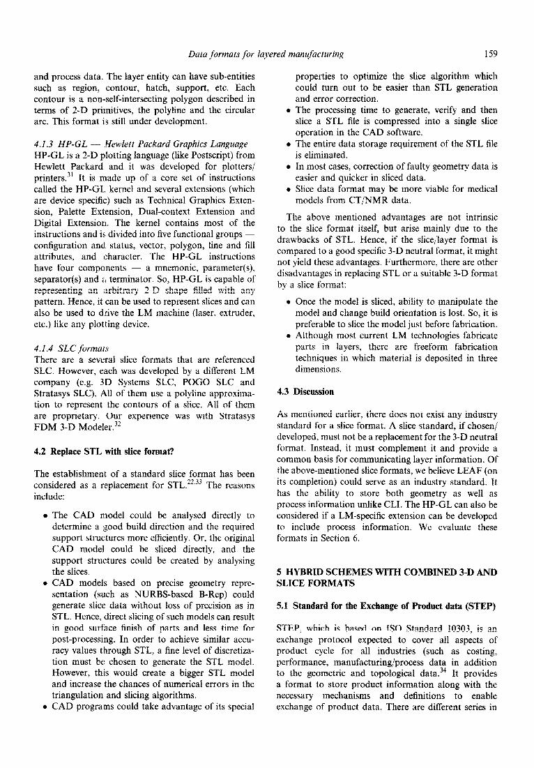
Table 1. Comparison of 3-D exchange formats
Issues Properties STL STH CFL RPI G-WORP STEP
Neutral exchange completeness no no no yes yes yes format issues neutral yes yes no yes no yes
specific yes yes yes yes yes no storage B B F G B G extensibility B B B G B G domain GM GM GM, TP GM, TP GM ALL conversion G G F G B G errors F F F F F G inspection F F G G B G
Secondary 3-D type TM TM FB FB, CG vx, SL BR, CG representation accuracy F F F F F G issues information B F F G F G
efficiency B B F G B G redundancy F F G G G G repairability F F F F F F
GM: geometry data, TP: topology data, PR: process data, ALL: all data - GM, TP and PR. G: good, F: fair, B: bad. TM: triangulated model, BR: boundary representation, FB: faceted boundary representation, CG: constructive solid geometry. VX: voxels, SL: slices.
Data formats for layered manufacturing 161
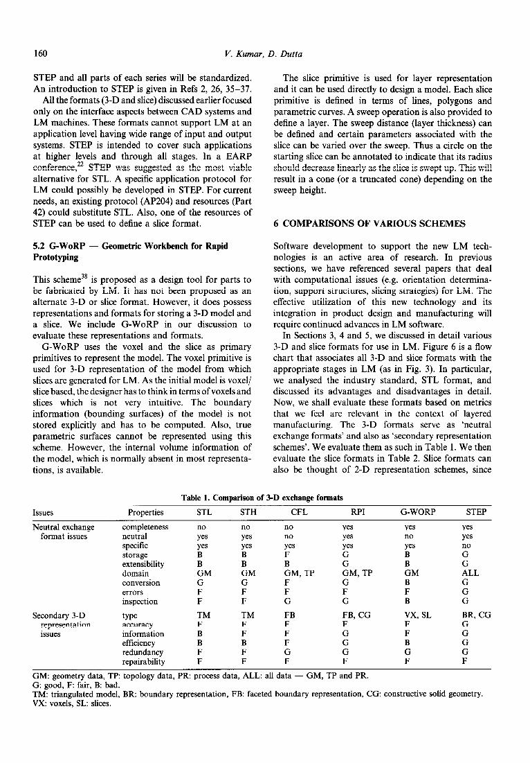
Table 2. Comparison of slice formats
Issues Properties CL1 LEAF SLC HP-GL G-WORP
Neutral exchange completeness yes yes yes yes yes format issues neutral yes yes no yes no
specific yes yes yes yes yes storage F G F F G extensibility F G F F F domain GM, TP ALL GM, TP GM, TP ALL conversion G G G G G errors G G G G G inspection G G G G G
2-D representation type PL PL, CA PL PL PL, PC issues accuracy F G F F G
information F G F F G efficiency G F G G redundancy cc G G G G repairability G G G G G
GM: geometry data, TP: topology data, PR: process data, and ALL: all data - GM. TP and PR. G: good, F: fair, B: bad. PL: polylines, CA: circular arcs, PC: parametric curves.
the distinction between a representation scheme and a format in 2-D is minimal.
Our choice of metrics in the two tabular evaluations reflects the factors we consider important. Note, most of these metrics are actually properties of representation schemes’ and neutral exchange formats.36 We believe these metrics provide a set of guidelines that would be helpful in future #efforts to standardize slice formats, as well as the 3-D exlchange formats. Also, the development of new 3-D exchange formats, 3-D representation schemes (for the process planning stage) and slice formats will benefit from this evaluation metric.
We list below ad metrics used in Table 1 and Table 2 and provide a brief explanation for each. The metrics have been grouped into the following categories: (i) neutral exchange formats and (ii) secondary 3-D representation schemes.
6.1 Neutral exchrrnge format issues
l Completeness: The neutral format must store all the required information (i.e. those necessary for the model to be fabricated in LM) present in the (primary) representation of the original model. This information must be retrievable without any loss.
l Neutral: The exchange format must be self- sufficient and must not depend on the initial input model. More specifically, it should satisfy the requirements, of a neutral format as discussed in Section 1.1.
l Specific: The format must be ‘specific neutral format’ such that it provides a ‘unified-input’ for the downstream processing in layered manufacturing.
l Storage: The format must be concise and should need minimum storage.
l Extensibility: The format should have the flexibility
to define new entities. This leaves enough scope for expanding the domain of the format.
l Domain: The format must be capable of receiving product data (e.g. geometry, topology, material,
3D SOURCE STAGE 1 SOURCE
3D solidmodel - CMM data MedicalAbel data 3D surface model Math data Layered data
IWWWZNTATION: B-Rep, CSG, Facets, Voxels, Point data, Contours etc.
FORMAT: Dependent on the CAD software
i
3D EXCHANGE FORMATS STAGE 2
LM SPECIFIC CAD/CAM
STL CFL IGES STH RPI STEP
I
PROCESS PLANNING STAGE 3
a,,..
J( SLICE FORhWlX
SLC CL1 LEAP HPGL STEP
I *
FABRICATION STAGE 4
Fig. 6. Flow chart of LM process - data representations/ formats and operations.
V. Kajar, D. Dutta
process, tolerances, etc.) from various 3-D sources.
o Conversion: The conversion to (and from) the neutral format must be easy without being computational intensive.
l Errors: The neutral format should not be prone to errors.
l Inspection: The neutral format must provide access for inspection and verification. If needed, minimal editing facilities must be provided.
These issues provide a basis for evaluating the LM-specific neutral formats. The issues related to representation schemes are given below.
6.2 Secondary 3-D representation issues
l Type: The representation scheme should be general, e.g. B-Rep, CSG, etc.
l VaZ~dity: The representation scheme should generate a valid model of the object to be represented.’
l Uniqueness: The representation should be unique and a particular object should have only one representation in this scheme.’
l Accuracy/approximation: The representation should not approximate the object unless such an approxi- mation is found sufficient by the user for post- processing.
l Information: The representation must possess all the necessary information (such as geometrical, topological, material, process, etc.) that are present in the original model.
l Deficiency: The representation should store data efficiently in its data structures so that algorithms can have fast data retrieval and manipulation (e.g. choosing a build direction, orienting the model, analysing the model to create support structures, creating slices etc.).
l Redundancy: The representation should not store too much redundant information. While the mini- mality of a representation impacts the storage requirements, it is sometimes essential to possess some redundant info~ation for increasing its efficiency.
l Repairability: The correction of errors in the representation that creep in during the data transfer must be easy and not time consuming.
The evaluations made in Tables 1 and 2 are based on the available information as presented in earlier sections. In our evaluation, we chose not to include IGES, a graphics-based exchange format. It was mainly designed to handle drawings, 3-D wire frame and surface models and recently, provisions for exchanging CSG and B-Rep data were added. Also, application
protocols (like in STEP) are being included in IGES. However, STEP surpasses IGES in all these aspects of product data exchange.37 Hence, we include STEP in this work because of its capability to address each application (LM in our case) in an organized manner through the concepts of integrated resources, descriptive languages and application protocols.
7 SUGARY AND CONCLUSIONS
In this paper, we considered the important issue of data representation and exchange in the emerging field of layered manufacturing. Specifically, we analysed the industry standard STL format, in detail. Then, we discussed various alternatives to the STL. Next, we considered slice/layer formats for which there does not yet exist an industry standard. We discussed several slice/layer formats in detail. Also, we considered ISO/ STEP as a possible alternative for the STL and slice formats. Then, we proposed a set of metrics for the compa~son of all 3-D and slice/layer formats. We used those metrics as a basis for comparison of the various 3-D and slice formats discussed in this paper.
Based on our analysis, we conclude that it would be advantageous to have a standard slice format. However, such a slice format should be developed not as a replacement for the 3-D exchange format, but to complement it. The complete elimination of the 3-D exchange format is not recommended for reasons outlined in Section 4. A standardized slice/layer format would enable the exchange of slice data that is vendor/pro~ess independent.
As mentioned at the outset, there is a growing dissatisfaction with the STL format among LM users. As outlined in Section 3, the STL does have several intrinsic problems as well as some that arise in the conversion process. However, the STL is not without its advan- tages. The reliability of surface triangulation algorithms is a major plus. Triangulation schemes yield a simple polyhedral (faceted) model and are fast and robust. Most importantly, all 3-D models from all sources (primary representations) can be triangulated efficiently. This leads to the unified-input property of STLs.
Insofar as we can determine, the STL format was developed to serve as an exchange format for the stereolithography process (the first commercial LM technology) and not designed to be an industry standard. Despite the current dissatisfaction, we believe that the STL has served, and continues to serve, the LM industry well. In our opinion, the selection of STL as the exchange format at the time was a prudent choice. During the early years, the LM industry was primarily focusing on process/hardware developments and rightly so. The prime concern on the CAD/software side, we believe, was to enable the largest input domain possible (i.e. importing CAD models from a variety of sources to
Data formats for layered manufacturing 163
create physical prototypes). The surface triangulation based STL format has certainly provided this capability. So, for example, if efforts are directed towards ‘repair’ of STL files (to fix errors that creep in), and the LM application domain remains essentially ‘design verifica- tion’, the STL representation would be quite adequate. While alternate mpresentations might possibly offer some advantages over STL, they would not be without their own drawbacks.
However, the question of whether the STL needs to be replaced can also be viewed in the context of the true potential of layered manufacturing. A fundamentally new capability of aill LM technologies is their capability to ‘deposit’ material. Already, there are technologies available that can selectively deposit materials, on a given layer. Mulri-material structures can therefore be manufactured. Furthermore, current hardware and material research in LM is also aimed at developing the capability to deposit materials with varying densities. (Note: recent advances in structural and material design can yield optimal product shapes having non- homogenous material distribution.) Therefore, the missing link in this product design and layered manufacturing environment is the capability to create a 3-D CAD model that can represent the ‘solid interior’. Further, we need to have 3-D exchange formats for such varying density models, and for layered manu- facturing we also need slice formats that can adequately represent (multi-) material information. The STL, in its present form, does not and cannot provide this capability, and therefore, alternatives to the STL need to be explored. To be fair, the authors are not aware of any other representation schemes that meet this criterion. This issue is of fundamental importance and research must first be directed towards the development of new 3-D representation schemes that model an object in its entirety (geometry, topology and material). This will, in turn, facilitate the development of slice and 3-D formats (i.e. STI, replacements) that contain full material/density information for LM.
REFERENCES
1. Requicha, A., Representations for rigid solids: theory, methods and systems. Comput. Surveys, 1980, 12 (4).
2. Kumar, V. & Dutta, D., An assessment of data formats for layered manufaa:uring. Technical report UM-MEAM- 22, Department Iof Mechanical Engineering, University of Michigan, Ann Arbor, November 1995.
3. Dolenc, A., An overview of RP technologies in manu- facturing. Report, Helsinki University of Technology, 1994.
4. Burns, M., Automated Fabrication. Prentice-Hall, Engle- wood Cliffs, NJ, 1992.
5. Kochan, D., Solid freeform manufacturing. In Manu- ,facturing Reseanrh & Technology. Elsevier, Amsterdam, 1993.
6.
7.
8.
9.
10.
11.
12.
13
14
Ashley, S., Rapid prototyping systems. Mech. Engng, April 1991, pp. 34-43. Jacobs, P. F., Rapid prototyping and manufacturing: fundamentals of stereolithography. Society of Manu- facturing Engineering, Dearborn, MI, 1992. Allen, S. & Dutta, D., Determination and evaluation of support structures in layered manufacturing. J. Design Man& 1995, 5, 153-162. Kulkarni, P. & Dutta, D., An accurate slicing procedure for layered manufacturing. Computer Aided Design, 1996, 28 (9), 683-697. Sreeram, P. & Dutta, D., Determination of optimal orientation based on variable slicing thickness in layered manufacturing. Proc. ASME Winter Annual Con& San Francisco, Nov. 1995. Suh, Y. S. & Wozny, M. J., Adaptive slicing for SFF processes. Proc. Solid Freeform Fabrication Conf., The University of Texas, Austin, July 1994. Aubin, R. F., A world wide assessment of rapid proto- typing technologies. Report, United Technologies Research Center, Jan 1994. Merz, M., Shape deposition manufacturing. Ph.D. Thesis, EDRC, Carnegie Mellon University, 1994. Bendsoe, M. P. & Kikuchi, N., Generating optimal topologies in structural design using a homogenization method. Comput. Meth. Appl. Mech. Engng, 1988. 71, 197-224.
15
16
17
18
Bendsoe, M. P.. Diaz, A. & Kikuchi, N., Topology and generalized layout optimization of elastic structures. In Topo1og.y Design of Structures, eds M. P. Bendsoe & C. A. MotaSoares. Kluwer Academic, Dordrecht. 1993, pp. 1599205. Moran, A., Madden, C., Rebis. R., Payne, R. & Matteson Jr., M. A., Spray forming technology for military applications. J. Thermal Spryv Technol., 1994, 3 (2). Marsan, A. & Dutta, D., Construction of a surface model and layered manufacturing data from 3D homogenization output. J. Mech. Des.. 1996, 118 (3) 412-418. Pacheco, J. M., State of the art review: rapid proto- typing for manufacturing. Abbreviated edition of MTIAC SOAR-93-01 for WWW (http://www.dtic.dla.mil/iac/ mtiac/RPINTRO.HTML). IIT Research Institute, March 1993.
19
20.
21.
22.
23.
Dolenc, A. & Makela, I., Rapid prototyping from a computer scientist’s point-of-view. Proc. Rapid Product Development Con& Stuttgart, Germany, 889 May 1995. Dolenc, A. & Makela, I., Rapid tools: a workbench for data transfer and data preparation for rapid prototyping. Technical Report, Institute of Industrial Automation, Helsinki University of Technology, April 1995. Bohn, J. H.. Automatic CAD-model repair. Ph.D. thesis, RPI, Troy, Aug. 1993. Data exchange for rapid prototyping. Report, EARP, July 1994.
24.
25.
26.
Jamieson. R.. CAD methods in rapid prototyping, WWW Report (http://www.cranfield.ac.uk/aero/rapid/EUROPE/ UK/CRANFIELD/jamiesonl .html), Cranfield University, Bedford, UK. Kirschman, C. F. et a/., The Clemson intelligent design editor for stereolithography. Proc. 2nd Int. Corzf. Rapid Prototyping, Dayton, OH, June 1991, pp. 2366241. Cubital Ltd. Solider 5600 System DFE &ware Installation and Maintenance Guide, Appendix C: Cubital Facet List (CFL) Guide Version 2.1. LaCourse, D. E.. Handbook of Solid Modeling. McGraw- Hill, New York, 1995.
27. Rock, S. J. & Wozny, M. J., A flexible file format for SFF.
164 V. Kumar. D. Dutta
Proc. Solid Freeform Fabrication Conf., University of Texas at Austin, Aug. 1991.
28. Common Layer Interface (CLZ). BRITE-EURAM Project BE5278, Rapid Prototyping Techniques, 1994.
29. A Data Exchange Format for LMT processes. BRITE- EURAM Project BE-3527-89, INSTANTCAM, October 1991.
30. The structure of LEAF. Draft from Martin Geiger, Fraunhofer Institute, Stuttgart, Germany, 1995.
3 1. The HP-GL/2 Reference Guide - A Handbook for Program Developers, Hewlett Packard, Addison-Wesley, Reading, MA, 1990.
32. FDM System Documentation. Reference Manual, Stratasys Inc., 1994.
33. Donahue, R. & Turner, R., CAD modeling and alternative methods of information transfer for rapid prototyping. 2nd Znt. Conf. Rapid Prototyping, Dayton, OH, June 1991, pp. 217-231.
34. Sutcliffe, G., CAD data for RP - harnessing the power of solid modelling. WWW Report (http://www.cranfield. ac.uk/aero/rapid/PROCEEDING/stucliff.html), SDRC, Stevenage, UK.
35. Owen, J., STEP: An Introduction. Information Geometers, Winchester, UK, 1993.
36. Helpenstein, H. J. (ed.), CAD Geometry Data Exchange Using STEP. ESPRIT Research Reports on Project 2195 (CADEX), Springer, Berlin, 1993.
37. National Product Data Exchange Resource Center, U.S. Product Data Association, WWW Report (http://wlib. cme.nist.gov/pub/nipde/), 1995.
38. Chandru, V. & Manohar, S., G-WORP: A Geometric Workbench for RP. Manufacturing Science and Engineering, PED series Vol. 68-2, ASME, 1994, pp. 569-574.
39. Dolenc, A., Rapid recipes for parametric surface models. Report, Helsinki University of Technology, 1994.
Related Documents