Advanced Material On TECHnology World best Product Key Components for IT & Energy industry based on advanced materials Copyright ⓒ 2014 Amotech corp. All right reserved. AMOTECH for Automotive Oct , 2014

Welcome message from author
This document is posted to help you gain knowledge. Please leave a comment to let me know what you think about it! Share it to your friends and learn new things together.
Transcript

Advanced Material On TECHnology
World best Product Key Components for IT & Energy industry based on
advanced materials
Copyright 2014 Amotech corp. All right reserved.
AMOTECH for Automotive
Oct , 2014
Advanced Material On TECHnology
Head office
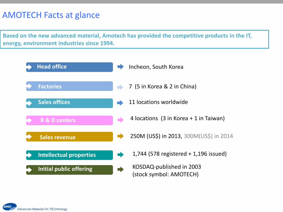
Based on the new advanced material, Amotech has provided the competitive products in the IT, energy, environment industries since 1994.
Incheon, South Korea
Factories 7 (5 in Korea & 2 in China)
Sales offices 11 locations worldwide
Sales revenue
Intellectual properties
R & D centers
Initial public offering
4 locations (3 in Korea + 1 in Taiwan)
250M (US$) in 2013, 300M(US$) in 2014
1,744 (578 registered + 1,196 issued)
KOSDAQ-published in 2003 (stock symbol: AMOTECH)
AMOTECH Facts at glance

Advanced Material On TECHnology
Automobile Laptop Mobile Chipset Appliance
Amotech presently supplies products to global companies as one of their major vendors over various fields, and is acknowledged in consumer market for its good credibility and reference.
AMOTECH Customers

Advanced Material On TECHnology
KOREA
CHINA
INCHEON POSEUNG SUCHAM HASUNG CHEONAN
AMOTECH Factories
Certified by TS16949 & ISO14001
QINGDAO ZIBO
Advanced Material On TECHnology
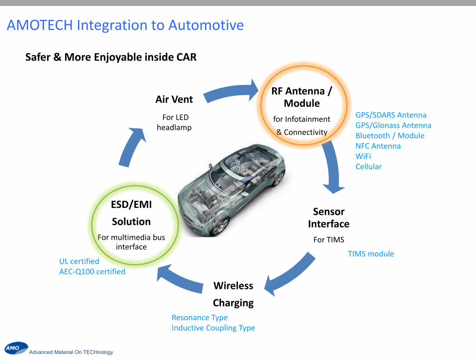
AMOTECH Integration to Automotive
RF Antenna / Module
for Infotainment
& Connectivity
Sensor Interface
For TIMS
Wireless
Charging
ESD/EMI
Solution
For multimedia bus interface
Air Vent
For LED headlamp
Safer & More Enjoyable inside CAR
GPS/SDARS Antenna GPS/Glonass Antenna Bluetooth / Module NFC Antenna WiFi Cellular
TIMS module
Resonance Type Inductive Coupling Type
UL certified AEC-Q100 certified

Advanced Material On TECHnology
AMOTECH History in Automotive Industry
Y2003
GPS Antenna SDARS Antenna Bluetooth Antenna
Y2013 Y2015 Y2009
GPS/Glonass NFC Module Wireless Charging
TPMS/TIMS Oxygen Sensor
ESD/EMI Components
Y2010 Y2011 Y2012 Y2014
Motorized Thermistor
Headlight Cooling fan for LED
Headlight Cooling fan for LED
Electric Water Pump

Advanced Material On TECHnology
Amotech Automotive Qualification
Quality Experience Man Power
TS16949 ISO14001 PPAP AEC-Q100
Dedicated team to support automotive customers
Pass several audit done by Top Tier 1 companies and automotive markers
Supplying various products to automotive customers for over 12 years
Infotainment
Connectivity
Body Electronics
Advanced Material On TECHnology
AMOTECH Antennas Solution
Advanced Material On TECHnology
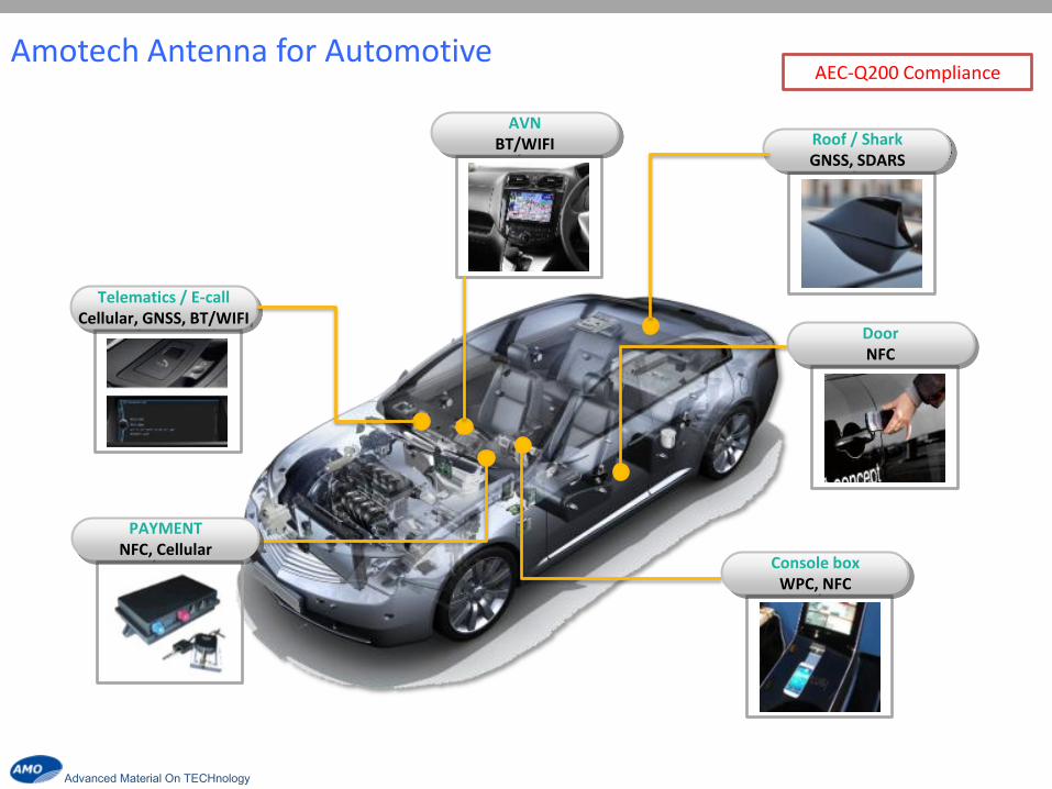
Amotech Antenna for Automotive
Telematics / E-call Cellular, GNSS, BT/WIFI
PAYMENT NFC, Cellular
Door NFC
Console box WPC, NFC
Roof / Shark GNSS, SDARS
AVN BT/WIFI
AEC-Q200 Compliance
Advanced Material On TECHnology
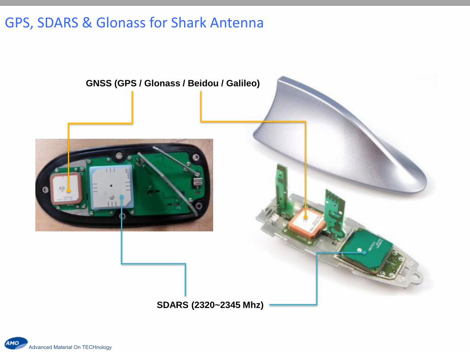
GNSS (GPS / Glonass / Beidou / Galileo)
SDARS (2320~2345 Mhz)
GPS, SDARS & Glonass for Shark Antenna
Advanced Material On TECHnology
0
1
2
3
4
5
1559 1563 1575 1595 1606 1610
0
1
2
3
4
5
1559 1563 1575 1595 1606 1610
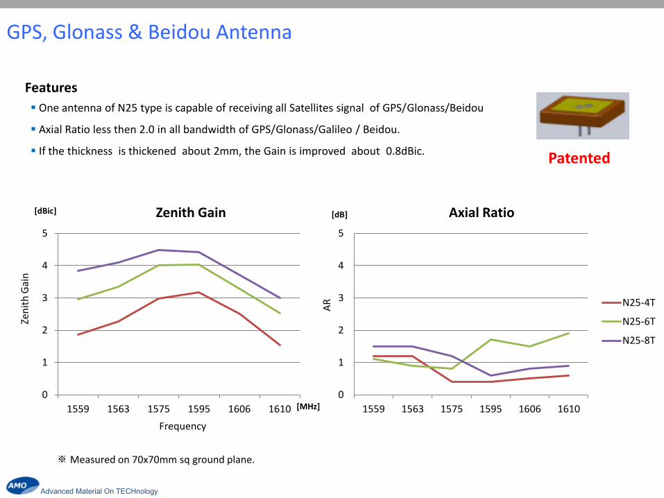
N25-4T
N25-6T
N25-8T
Zenith Gain Axial Ratio [dBic]
[MHz]
Zen
ith
Gai
n
Frequency
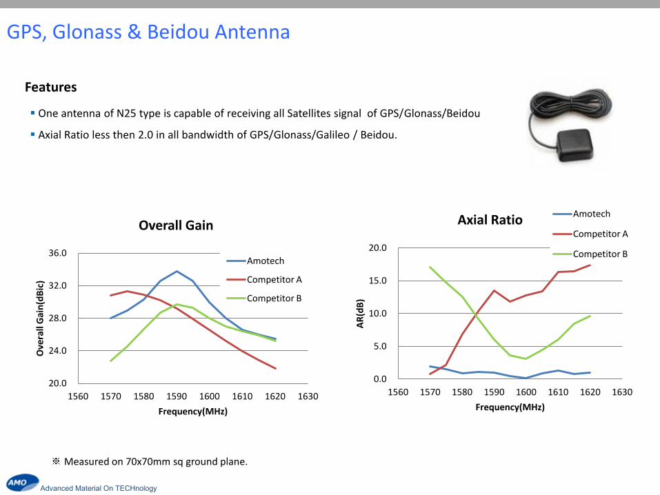
※ Measured on 70x70mm sq ground plane.
One antenna of N25 type is capable of receiving all Satellites signal of GPS/Glonass/Beidou
Axial Ratio less then 2.0 in all bandwidth of GPS/Glonass/Galileo / Beidou.
If the thickness is thickened about 2mm, the Gain is improved about 0.8dBic.
Features
Patented
AR
[dB]
GPS, Glonass & Beidou Antenna
Advanced Material On TECHnology
※ Measured on 70x70mm sq ground plane.
One antenna of N25 type is capable of receiving all Satellites signal of GPS/Glonass/Beidou
Axial Ratio less then 2.0 in all bandwidth of GPS/Glonass/Galileo / Beidou.
0.0
5.0
10.0
15.0
20.0
1560 1570 1580 1590 1600 1610 1620 1630
AR
(dB
)
Frequency(MHz)
Axial Ratio Amotech
Competitor A
Competitor B
20.0
24.0
28.0
32.0
36.0
1560 1570 1580 1590 1600 1610 1620 1630
Ove
rall
Gai
n(d
Bic
)
Frequency(MHz)
Overall Gain
Amotech
Competitor A
Competitor B
GPS, Glonass & Beidou Antenna
Features

Advanced Material On TECHnology
H.C H.C LP LP
LP
CP
LP CP
Pre- Coupler Pre- LNA
Old New
Satellite AGA363913-S0-A1
(Pre- Coupler) New AGA363913-S0-A5
(Pre-LNA) Remark
GPS 45 46~48 1~3dB UP
Glonass 43~44 44~46 1~2dB UP
Beidou 40~41 42~43 2dB UP
GPS, Glonass & Beidou Antenna
Advanced Material On TECHnology
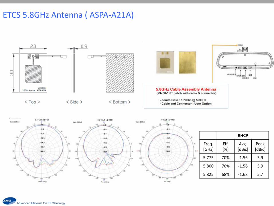
ETCS 5.8GHz Antenna ( ASPA-A21A)
RHCP
Freq. [GHz]
Eff. [%]
Avg. [dBic]
Peak [dBic]
5.775 70% -1.56 5.9
5.800 70% -1.56 5.9
5.825 68% -1.68 5.7

Advanced Material On TECHnology
T
y
p
e
Chip
PCB + Cable
Bluetooth & WiFi for AVN
AVN system

Advanced Material On TECHnology
5GHZ Chip Antenna (AMAN103015ST04)
Product performance
Product Features
- WLAN 5GHz (5150~5850 MHz) for IEEE 802.11 a / ac
- SMD chip type (10 x 3.0 x 1.5 mm3)
- Wide bandwidth
- SMT available under Pb-free condition
Frequency
[MHz]
Peak gain
[dBi]
Avg. Gain
[dBi]
Efficiency
[%]
5150 2.6 -1.1 77
5500 3.5 -0.6 87
5850 3.5 -1.1 77
No Pin Assignment
① Feeding
② N/C
③ N/C [unit : mm]
VSWR Antenna gain [Efficiency] Antenna gain [Avg. gain]
3D radiation pattern @5500MHz
PCB design guide

Advanced Material On TECHnology
Product performance
Product Features
- WLAN 5GHz (5150~5850 MHz) for IEEE 802.11 a / ac
- SMD chip type (10 x 3.0 x 1.5 mm3)
- Wide bandwidth
- SMT available under Pb-free condition
No Pin Assignment
① Feeding
② GND
③ GND
VSWR Antenna gain [Efficiency] Antenna gain [Avg. gain]
3D radiation pattern @5500MHz
PCB design guide
[unit : mm]
Frequency
[MHz]
Peak gain
[dBi]
Avg. Gain
[dBi]
Efficiency
[%]
5150 2.3 -1.1 77
5500 3.6 -0.2 96
5850 3.4 -0.7 85
5GHZ Chip Antenna (AMAN103015ST05)

Advanced Material On TECHnology
Product performance
Product features
- Dual WLAN for IEEE 802.11 n
(2.4+5GHz)
- SMD chip type (10 x 3.0 x 1.5 mm3)
- PIFA structure
- SMT available under Pb-free condition
2442MHz Peak gain
[dBi]
Avg. Gain
[dBi]
Efficiency
[%]
Azimuth 1.88 0.9
92 Elevation 1 1.72 -1.08
Elevation 2 1.39 -0.03
No Pin Assignment
① Feeding
② GND
③ GND
④ N/C
VSWR of Antenna (2.4GHz)
3D radiation pattern @2442MHz
PCB design guide
VSWR of Antenna (5GHz)
3D radiation pattern @5500MHz
2500MHz Peak gain
[dBi]
Avg. Gain
[dBi]
Efficiency
[%]
Azimuth 3.60 -0.09
79 Elevation 1 3.08 -1.79
Elevation 2 -3.52 -7.16
[unit : mm]
Dual WLAN Antenna (AMAN103015ST07)

Advanced Material On TECHnology
GPS & GLONASS Chip Antenna(AMAN 1003015ST03)
Product performance
Product Features
- GPS(1575.42 MHz) & Glonass(1592~1610 MHz) available
- SMD chip type (10 x 3.0 x 1.5 mm3)
- PIFA structure
- SMT available under Pb-free condition
1575 MHz Peak gain
[dBi]
Avg. Gain
[dBi]
Efficiency
[%]
Azimuth 2.96 1.27
87.3 Elevation 1 2.73 -1.86
Elevation 2 2.09 -1.24
No Pin Assignment
① Feeding
② GND
③ GND
④ N/C
VSWR of Antenna (2.4GHz) PCB design guide
3D radiation pattern 1575MHz
1600 MHz Peak gain
[dBi]
Avg. Gain
[dBi]
Efficiency
[%]
Azimuth 2.89 1.12
87.1 Elevation 1 2.73 -1.86
Elevation 2 2.22 -1.18
[unit : mm]
① ② ③ ④
3D radiation pattern 1600MHz GPS Glonass
Advanced Material On TECHnology
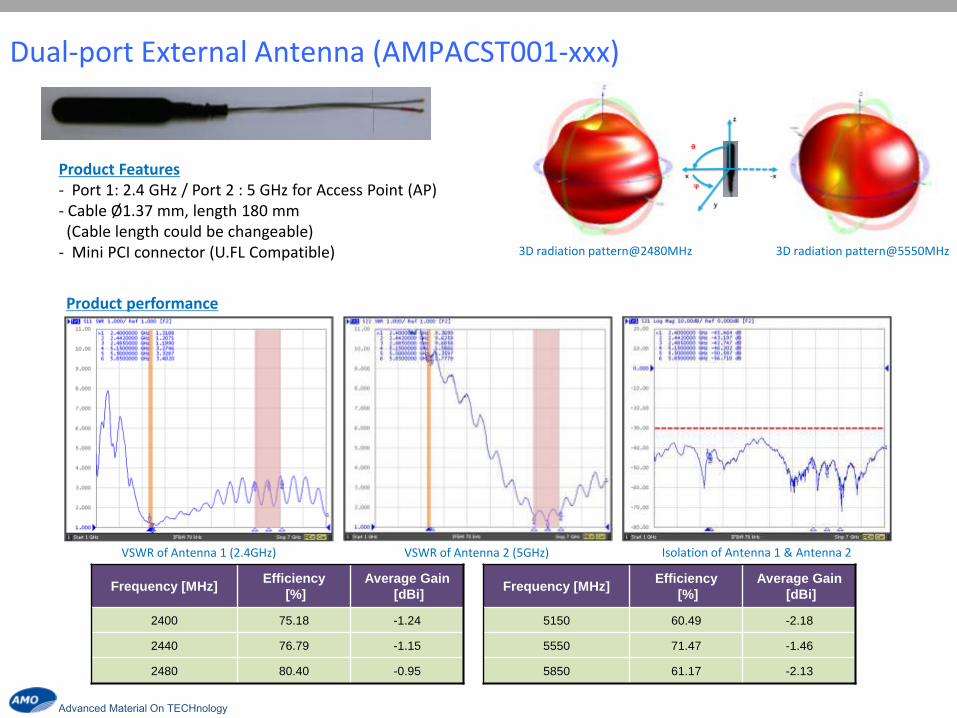
Dual-port External Antenna (AMPACST001-xxx)
Product Features - Port 1: 2.4 GHz / Port 2 : 5 GHz for Access Point (AP) - Cable Ø 1.37 mm, length 180 mm (Cable length could be changeable) - Mini PCI connector (U.FL Compatible)
VSWR of Antenna 1 (2.4GHz) VSWR of Antenna 2 (5GHz) Isolation of Antenna 1 & Antenna 2
Frequency [MHz] Efficiency
[%]
Average Gain
[dBi]
2400 75.18 -1.24
2440 76.79 -1.15
2480 80.40 -0.95
Product performance
3D radiation pattern@2480MHz 3D radiation pattern@5550MHz
Frequency [MHz] Efficiency
[%]
Average Gain
[dBi]
5150 60.49 -2.18
5550 71.47 -1.46
5850 61.17 -2.13
Advanced Material On TECHnology
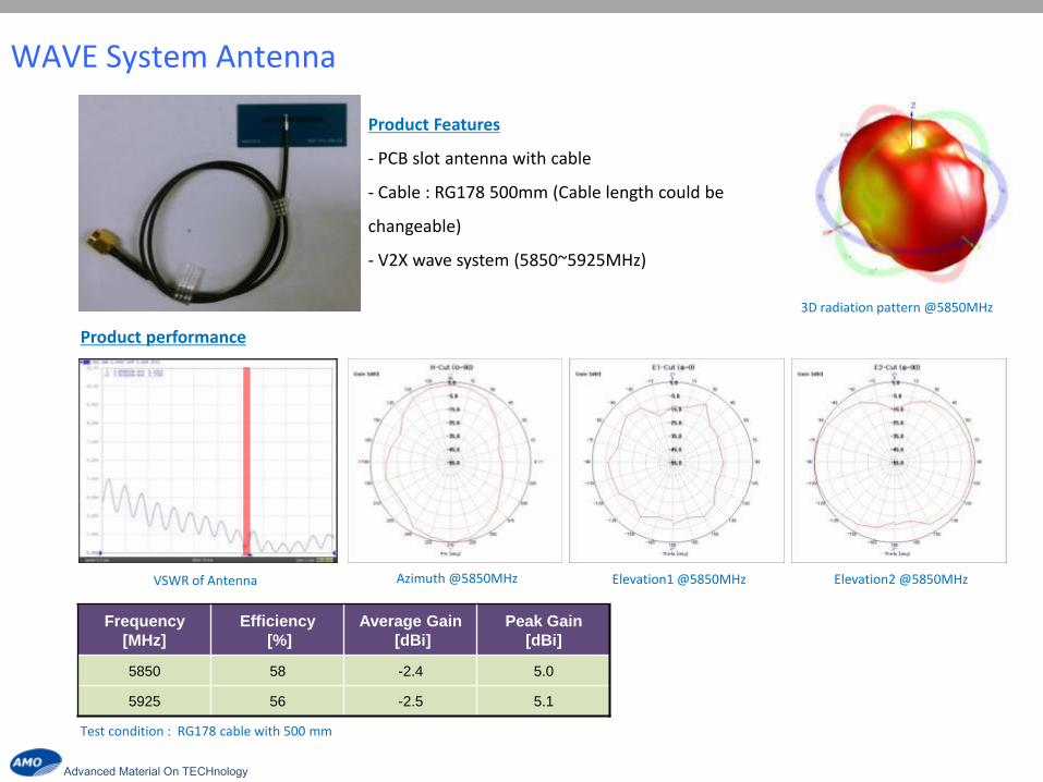
WAVE System Antenna
Frequency
[MHz]
Efficiency
[%]
Average Gain
[dBi]
Peak Gain
[dBi]
5850 58 -2.4 5.0
5925 56 -2.5 5.1
Product performance
Product Features
- PCB slot antenna with cable
- Cable : RG178 500mm (Cable length could be
changeable)
- V2X wave system (5850~5925MHz)
Azimuth @5850MHz Elevation1 @5850MHz Elevation2 @5850MHz
3D radiation pattern @5850MHz
Test condition : RG178 cable with 500 mm
VSWR of Antenna
Advanced Material On TECHnology
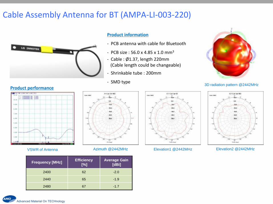
Cable Assembly Antenna for BT (AMPA-LI-003-220)
Product information
- PCB antenna with cable for Bluetooth
- PCB size : 56.0 x 4.85 x 1.0 mm3
- Cable : Ø 1.37, length 220mm (Cable length could be changeable)
- Shrinkable tube : 200mm
- SMD type Product performance
Azimuth @2442MHz Elevation1 @2442MHz Elevation2 @2442MHz VSWR of Antenna
Frequency [MHz] Efficiency
[%]
Average Gain
[dBi]
2400 62 -2.0
2440 65 -1.9
2480 67 -1.7
3D radiation pattern @2442MHz

Advanced Material On TECHnology
AMOTECH NFC Solution for Automotive
Type Application AMOTECH Products
NFC Tag ( Including IC)
NFC Antenna (Reader Mode)
NFC Module (Turnkey Solution)
14.48x13.46mm 17.0 x 10.0mm 20.0 x 6.0mm

Advanced Material On TECHnology
NFC Application for Automotive
Keyless entry via mobile phone
Easy & secure connections for BT & WiFi
Personalization
Car information / Diagnosis
Smart Phone integration & Mirroring
Car Sharing & Payment
Advanced Material On TECHnology
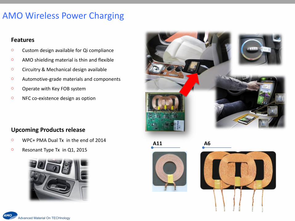
Features
Custom design available for Qi compliance
AMO shielding material is thin and flexible
Circuitry & Mechanical design available
Automotive-grade materials and components
Operate with Key FOB system
NFC co-existence design as option
Upcoming Products release
WPC+ PMA Dual Tx in the end of 2014
Resonant Type Tx in Q1, 2015
AMO Wireless Power Charging
A11 A6
Advanced Material On TECHnology Advanced Material On TECHnology
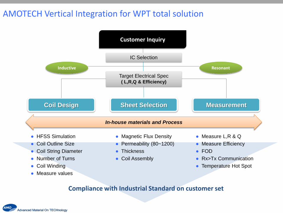
AMOTECH Vertical Integration for WPT total solution
Coil Design Sheet Selection Measurement
HFSS Simulation
Coil Outline Size
Coil String Diameter
Number of Turns
Coil Winding
Measure values
Magnetic Flux Density
Permeability (80~1200)
Thickness
Coil Assembly
Measure L,R & Q
Measure Efficiency
FOD
Rx>Tx Communication
Temperature Hot Spot
Customer Inquiry
Target Electrical Spec ( L,R,Q & Efficiency)
IC Selection
In-house materials and Process
Resonant Inductive
Compliance with Industrial Standard on customer set

Advanced Material On TECHnology Advanced Material On TECHnology
AMOTECH Design Simulation

Advanced Material On TECHnology
Wireless Power Charging Solution
MCU Controller
Power
Controller
DCDC
Charger Rectifier
Information
AC Adaptor MCU
Fle
xib
le B
att
ery
Total Solution Provider for Wireless Power Control and RF connectivity
Rx / Tx Antenna Coil
Backing sheets for efficiency enhancement
Rx/Tx Module Assembly
Tx Rx
Advanced Material On TECHnology
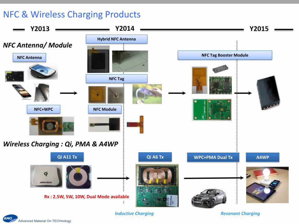
2013 Y2013 Y2014 Y2015
NFC Antenna
NFC+WPC
Qi A11 Tx
Hybrid NFC Antenna
NFC Tag
NFC Module
Qi A6 Tx
NFC Tag Booster Module
A4WP
Inductive Charging Resonant Charging
NFC & Wireless Charging Products
WPC+PMA Dual Tx
NFC Antenna/ Module
Wireless Charging : Qi, PMA & A4WP
Rx : 2.5W, 5W, 10W, Dual Mode available
Advanced Material On TECHnology
Automotive EMC Solution
Advanced Material On TECHnology
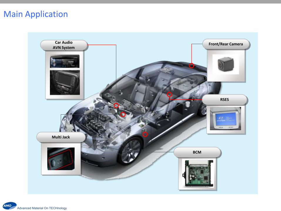
Front/Rear Camera
BCM
Multi Jack
RSES
Car Audio AVN System
Main Application

Advanced Material On TECHnology
EMI & ESD Solution
Category RLC network
EMI ESD filter
Common mode ESD filter
Series Name /
Size
ADF series
2012 mm
AHF series
1210/2012 mm
Figures
※ AEC-Q200 compliance
Car Audio AVN Multi-jack RSES Cam. BCM
RGB I/O LVDS SD
card HDMI
USB 2.0
Aux RGB LVDS RGB CAN
E S D
AVL Series
AIES Series
E M I
ADF Series
AHF Series
ESD / Surge Solution
Category Chip Varistor ESD suppressor
Series Name /
Size
AVL/AV series
1608/2016/2520mm
AIES series
1005/1608
Figures
Automotive EMC solution
Advanced Material On TECHnology
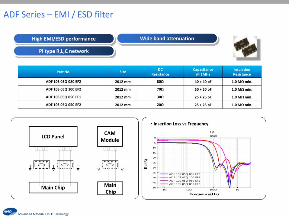
High EMI/ESD performance Wide band attenuation
Pi type R,L,C network
Part No. Size DC
Resistance Capacitance
@ 1MHz Insulation Resistance
ADF 10S 05Q 080 EF2 2012 mm 80Ω 40 + 40 pF 1.0 MΩ min.
ADF 10S 05Q 100 EF2 2012 mm 70Ω 50 + 50 pF 1.0 MΩ min.
ADF 10S 05Q 050 EF1 2012 mm 30Ω 25 + 25 pF 1.0 MΩ min.
ADF 10S 05Q 050 EF2 2012 mm 20Ω 25 + 25 pF 1.0 MΩ min.
LCD Panel
Main Chip
Insertion Loss vs Frequency
1M 10M 100M 1G-50
-45
-40
-35
-30
-25
-20
-15
-10
-5
0
ADF 10S 05Q 080 EF2
ADF 10S 05Q 100 EF2
ADF 10S 05Q 050 EF1
ADF 10S 05Q 050 EF2
IL(d
B)
Frequency(Hz)
CAM Module
Main Chip
FM Band
ADF Series – EMI / ESD filter
Advanced Material On TECHnology
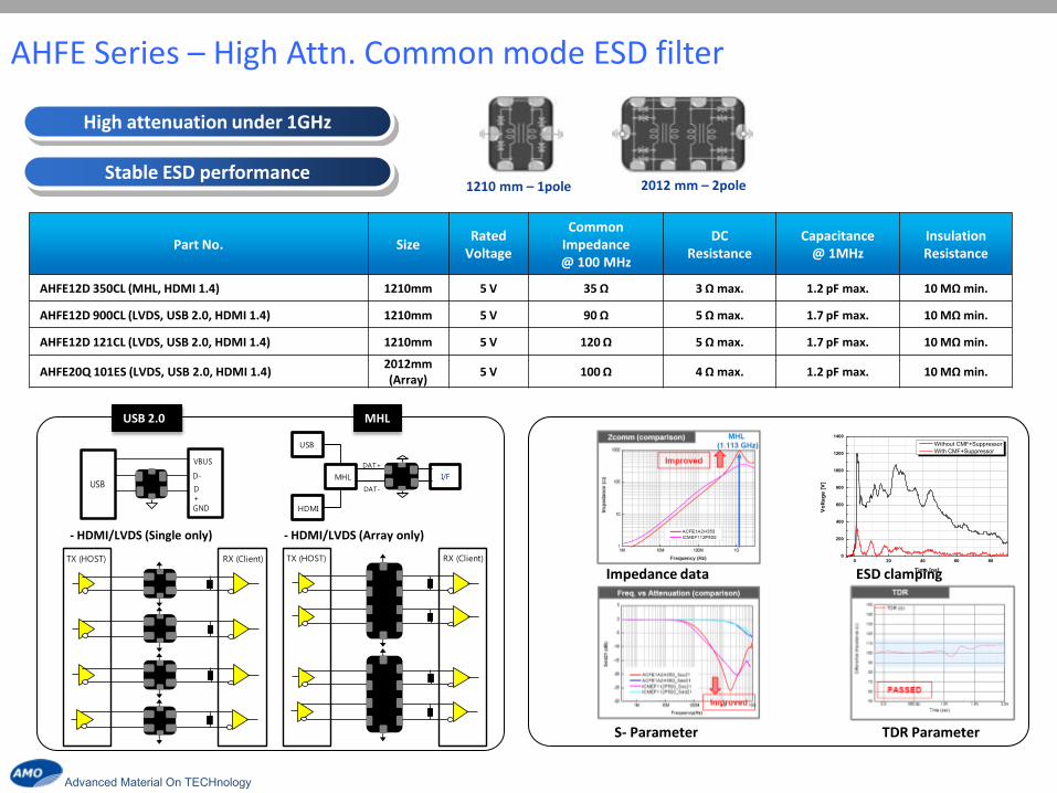
USB 2.0 MHL
- HDMI/LVDS (Single only) - HDMI/LVDS (Array only)
High attenuation under 1GHz
Stable ESD performance
0 20 40 60 800
200
400
600
800
1000
1200
1400
Vo
lta
ge
[V
]
Time [ns]
Without CMF+Suppressor
With CMF+Suppressor
Impedance data ESD clamping
TDR Parameter S- Parameter
Part No. Size Rated
Voltage
Common Impedance @ 100 MHz
DC Resistance
Capacitance @ 1MHz
Insulation Resistance
AHFE12D 350CL (MHL, HDMI 1.4) 1210mm 5 V 35 Ω 3 Ω max. 1.2 pF max. 10 MΩ min.
AHFE12D 900CL (LVDS, USB 2.0, HDMI 1.4) 1210mm 5 V 90 Ω 5 Ω max. 1.7 pF max. 10 MΩ min.
AHFE12D 121CL (LVDS, USB 2.0, HDMI 1.4) 1210mm 5 V 120 Ω 5 Ω max. 1.7 pF max. 10 MΩ min.
AHFE20Q 101ES (LVDS, USB 2.0, HDMI 1.4) 2012mm (Array)
5 V 100 Ω 4 Ω max. 1.2 pF max. 10 MΩ min.
TX (HOST) RX (Client) TX (HOST) RX (Client)
D-
D+
VBUS
GND
USB
USB
HDMI
MHL I/F
DAT-
DAT+
2012 mm – 2pole 1210 mm – 1pole
AHFE Series – High Attn. Common mode ESD filter
Advanced Material On TECHnology
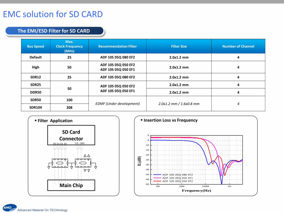
Bus Speed Max.
Clock Frequency (MHz)
Recommendation Filter Filter Size Number of Channel
Default 25 ADF 10S 05Q 080 EF2 2.0x1.2 mm 4
High 50 ADF 10S 05Q 050 EF2 ADF 10S 05Q 050 EF1
2.0x1.2 mm 4
SDR12 25 ADF 10S 05Q 080 EF2 2.0x1.2 mm 4
SDR25 50
ADF 10S 05Q 050 EF2 ADF 10S 05Q 050 EF1
2.0x1.2 mm 4
DDR50 2.0x1.2 mm 4
SDR50 100 EDMF (Under development) 2.0x1.2 mm / 1.6x0.8 mm 4
SDR104 208
Insertion Loss vs Frequency
1M 10M 100M 1G-50
-45
-40
-35
-30
-25
-20
-15
-10
-5
0
ADF 10S 05Q 080 EF2
ADF 10S 05Q 050 EF1
ADF 10S 05Q 050 EF2
IL(d
B)
Frequency(Hz)
SD Card Connector
Main Chip
CLK CMD D0 D1 D2 D3
Filter Application
The EMI/ESD Filter for SD CARD
EMC solution for SD CARD

Advanced Material On TECHnology
AIES Series - ESD solution for High Speed
USB 2.0
Antenna
※ Key point : : in contrast with competitor, AIES Series has excellent reduction characteristics and a lower price.
ESD Clamping
Eye pattern (at 2.25Gbps)
S- Parameter
Ultra low capacitance (0.1pF)
Destruction mode is open type
- Application : Touch Key, USB2.0, RF circuit
Part No. Size Rated Voltage Clamping Voltage Capacitance Destruction mode
AIES 12U 02 AG1 1005 mm 12V 40 typ 0.1 pF typ. OPEN Type
ASM /FEM
ESD Suppressor
Antenna
Matching Circuit
DC Block
external I/F
D-
D+
USB2.0/ Ethernet
TDR test
0 20 40 60 80 100
0
300
600
900
1200
1500
1800
Vo
ltag
e [V
]Time [ns]
Open Waveform
AIES 12U 02 0R2
1M 10M 100M 1G-30
-20
-10
0
ESD suppressor (0.2pF)
Low cp varistor (3.3pF)
IL(d
B)
Frequency(Hz)

Advanced Material On TECHnology
AVL Series – General ESD solution
Stable protection level
Jump start Endurance
Part No. Size
[mm]
Varistor Voltage
[V]
Capacitance [pF]
Clamping Voltage @ 1A, 8/20us pulse
[V]
Imax @ 8/20us pulse
[A]
AVLC 18S 03 015 1608 28 15 65 2
AVLC 18S 03 030 1608 28 30 65 2
AVL 18S 03 300 LC75 1608 27 75 45 30
AVL 18S 03 300 LC120 1608 27 120 45 30
AVMC 18S 03 220 1608 24.5 200 42 60
-20 0 20 40 60 80 100
0
400
800
1200
1600
Vo
ltag
e [V
]
Time [ns]
Standard waveform(ESD 8kV contact)
Automotive Series 0603 Size
Advanced Material On TECHnology
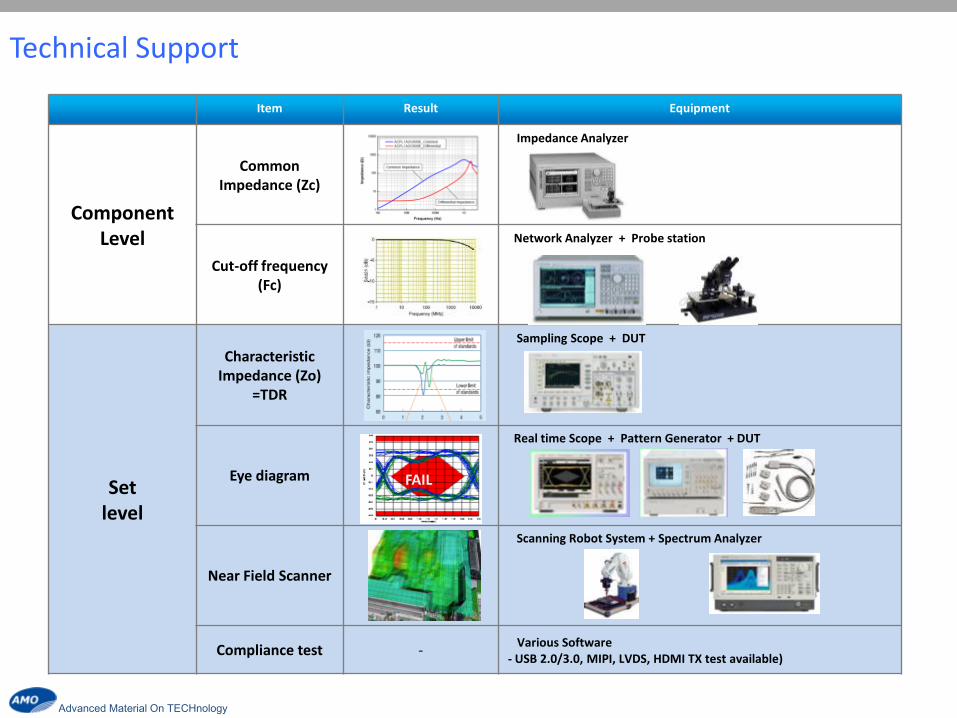
Technical Support
Item Result Equipment
Component Level
Common Impedance (Zc)
Impedance Analyzer
Cut-off frequency (Fc)
Network Analyzer + Probe station
Set level
Characteristic Impedance (Zo)
=TDR
Sampling Scope + DUT
Eye diagram
Real time Scope + Pattern Generator + DUT
Near Field Scanner
Scanning Robot System + Spectrum Analyzer
Compliance test - Various Software - USB 2.0/3.0, MIPI, LVDS, HDMI TX test available)
FAIL
Advanced Material On TECHnology
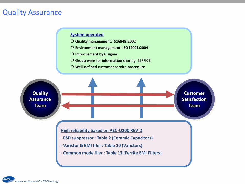
Quality Assurance
Customer Satisfaction
Team
Quality Assurance
Team
System operated
Quality management:TS16949:2002
Environment management: ISO14001:2004
Improvement by 6 sigma
Group ware for information sharing: SEFFICE
Well-defined customer service procedure
High reliability based on AEC-Q200 REV D
- ESD suppressor : Table 2 (Ceramic Capacitors)
- Varistor & EMI filer : Table 10 (Varistors)
- Common mode filer : Table 13 (Ferrite EMI Filters)
Related Documents