Weir Minerals Latin America Vulco Perú S.A. Excellent Minerals Solutions Installation, Operation & Maintenance WARMAN PUMP Model 6 FF-AHF SOC. MINERA EL BROCAL S.A.A. TAG: PP-30 O/C: 4986 OF: 71289 S/N: VP-2012-214 Av. Separadora Industrial 2201 Ate – Lima, Perú T: +51 1! "1#$5$5 %: ventas&'eirminerals.(om.pe ): '''.'eirminerals.(om

Welcome message from author
This document is posted to help you gain knowledge. Please leave a comment to let me know what you think about it! Share it to your friends and learn new things together.
Transcript

8/15/2019 r1_OF 71289_6 FF-AHF
http://slidepdf.com/reader/full/r1of-712896-ff-ahf 1/333
Weir Minerals Latin AmericaVulco Perú S.A.
ExcellentMineralsSolutions
Installation, Operation & Maintenance
WARMAN PUMPModel
6 FF-AHF
SOC. MINERAEL BROCAL
S.A.A.
TAG: PP-30
O/C: 4986
OF: 71289
S/N: VP-2012-214 Av. Separadora Industrial 2201Ate – Lima, Perú
T: +51 1! "1#$5$5%: ventas&'eirminerals.(om.pe
): '''.'eirminerals.(om

8/15/2019 r1_OF 71289_6 FF-AHF
http://slidepdf.com/reader/full/r1of-712896-ff-ahf 2/333
Weir Minerals Latin AmericaVulco Perú S.A.
ExcellentMineralsSolutions
Installation, Operation & Maintenance
INDEX
I. Drawing List
1. General Arrangement Drawing2. Curve3. Component Diagram4. Bearing Assembly5. Part List
II. Assembly and Maintenance Instructions - SUPPLEMENT “M1”General Instructions Applicable to All Types of Warman Pumps
III. Assembly and Maintenance Instructions - SUPPLEMENT “P3”Series “A” Slurry Pumps – Type “AH & M”
IV. Assembly and Maintenance Instructions - SUPPLEMENT “BA3”Modified Basic Bearing Assembly (Warman Basic Number 005)(Frame Sizes CC, DD, EE, FF & GG)
V. Assembly and Maintenance Instructions – SUPPLEMENT “M09”Gland Sealing
VI. Assembly and Maintenance Instructions – SUPPLEMENT “P50”Horizontal Froth Pumps (AHF, MF & LF)
VII. Annex.
1. Motor Manual2. Gear Reducer Manual3. Couplings Manual

8/15/2019 r1_OF 71289_6 FF-AHF
http://slidepdf.com/reader/full/r1of-712896-ff-ahf 3/333
8/15/2019 r1_OF 71289_6 FF-AHF
http://slidepdf.com/reader/full/r1of-712896-ff-ahf 4/333
1 0 2 0 3 0 4 0 5 0 6 0 7 0 8 0 9 0
4 0 0
8 0 0
1 2 0 0
1 6 0 0
E F F I C I E N C Y
N P S H r
4 0 0 r p m
5 0 0 r p m
6 0 0 r p m
7 0 0 r p m
8 0 0 r p m
9 0 0 r p m
1 0 0 0 r p m
1 1 0 0 r p m
3 0 %
4 0 %
5 0 %
5 5 %
6 0 %
6 2 %
6 3 . 5 %
6 2 %
6 0 %
2m
2.5m
3m
3.5m
4.5m
4m
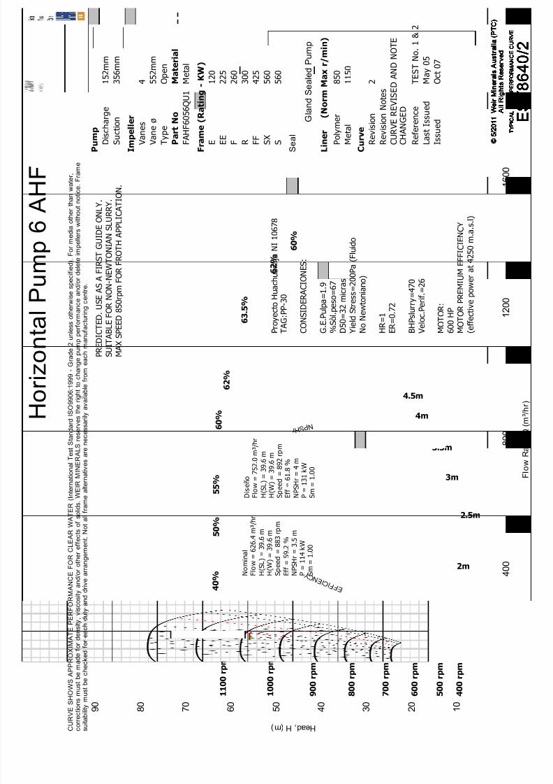
D i s e ñ o
F l o w =
7 5 2 . 0 m
³ / h r
H ( S L ) =
3 9 . 6 m
H ( W ) =
3 9 . 6 m
S p e e d =
8 9 2 r p m
E f f =
6 1 . 8 %
N P S H r =
4 m
P =
1 3 1 k W
S m =
1 . 0 0
P r o y e c t o H u a c h u a c a
j a N I 1 0 6 7 8
T A G : P P - 3 0
C O N S I D E R A C I O N E S :
G . E .
P u l p a = 1 . 9
% S ò l . p e s o = 6 7
D 5 0 = 3 2 m
i c r a s
Y i e l d S t r e s s = 2 0 0 P a ( F l u i d o
N o
N e w
t o n i a n o )
H R = 1
E R = 0 . 7 2
B H P s l u r r y = 4 7 0
V e l o c . P e r i f . = 2 6
M O T O R :
6 0 0 H P
M O T O R P R E M I U M E F F I C I E N C Y
( e f f e c t i v e p o w e r a t 4
2 5 0 m . a .
s . l )
N o m
i n a l
F l o w =
6 2 6 . 4 m ³ /
h r
H ( S L ) =
3 9 . 6 m
H ( W ) =
3 9 . 6 m
S p e e d =
8 8 3 r p m
E f f =
5 9 . 2 %
N P S H r =
3 . 5 m
P =
1 1 4 k W
S m =
1 . 0 0
P R E D I C T E D
. U S E A S A F I R S T G U I D E O N L Y .
S U I T A B L E F O R N O N - N
E W T O N I A N S L U R R Y .
M A X S P E E D 8 5 0 r p m F O R F R O T H A P P L I C A T I O N
.
H e a d , H ( m )
F l o w
R a
t e ,
Q ( m ³ / h r ) H o
r i z o n t a l P u m p 6 A H F
C U R V E S H O W S A P P R O X I M A T E P E R F O R M A N C E F O R C L E A R W A T E R ( I n t e r n a t i o n a l T e s t
S t a n d a r d I S O 9 9 0 6 : 1 9 9 9 -
G r a d e
2 u n l e s s o t h e r w
i s e s p e c i f i e d ) .
F o r m e d i a o t h e r
t h a n w a t e r ,
c o r r e c t i o n s m u s t
b e m a d e
f o r d e n s i t y , v i s c o s i t y a n d / o r o t h e r e f f e c t s o
f s o l i d s .
W E I R M I N E R A L S r e s e r v e s
t h e r i g h
t t o c h a n g e p u m p p e r f o r m a n c e a n d / o r
d e l e t e
i m p e l l e r s w
i t h o u t n o t i c e .
F r a m e
s u i t a b i l i t y m u s t
b e c h e c k e
d f o r e a c h
d u t y a n d
d r i v e a r r a n g e m e n t .
N o t a l l f r a m e a l t e r n a t i v e s a r e n e c e s s a r i l y a v a i l a
b l e f r o m e a c h m a n u f a c t u r i n g c e n t r e .
P u m p
1 5 2 m m
D i s c h a r g e
3 5 6 m m
S u c t i o n
© 5 / 2 0 1 1 W e i r
M i n e r a l s A u s t r a l i a
( P T C )
A l l R i g h t s R e s e r v e d
T Y P I C A L P U M P P E R F O R M A N C E C U R V E
E S Y 8 6 4 0 / 2
I m p e
l l e r
4
V a n e s
5 5 2 m m
V a n e ø
O p e n
T y p e
M a t e r i a l
P a r t N o
M e t a l
F A H F 6 0 5 6 Q U 1
© 5 / 2 0 1 1 W e i r
M i n e r a l s A u s t r a l i a
( P T C )
A l l R i g h t s R e s e r v e d
T Y P I C A L P U M P P E R F O R M A N C E C U R V E
E S Y 8 6 4 0 / 2
F r a m e
( R a t i n g -
K W )
1 2 0
E
2 2 5
E E
2 6 0
F
3 0 0
R
4 2 5
F F
5 6 0
S X
5 6 0
S © 5 / 2 0 1 1 W e i r
M i n e r a l s A u s t r a l i a
( P T C )
A l l R i g h t s R e s e r v e d
T Y P I C A L P U M P P E R F O R M A N C E C U R V E
E S Y 8 6 4 0 / 2
S e a l
G l a n d S e a l e d
P u m p
© 5 / 2 0 1 1 W e i r
M i n e r a l s A u s t r a l i a
( P T C )
A l l R i g h t s R e s e r v e d
T Y P I C A L P U M P P E R F O R M A N C E C U R V E
E S Y 8 6 4 0 / 2
L i n e r
( N o r m
M a x r / m
i n )
8 5 0
P o l y m e r
1 1 5 0
M e t a
l
© 5 / 2 0 1 1 W e i r
M i n e r a l s A u s t r a l i a
( P T C )
A l l R i g h t s R e s e r v e d
T Y P I C A L P U M P P E R F O R M A N C E C U R V E
E S Y 8 6 4 0 / 2
© 5 / 2 0 1 1 W e i r
M i n e r a l s A u s t r a l i a
( P T C )
A l l R i g h t s R e s e r v e d
T Y P I C A L P U M P P E R F O R M A N C E C U R V E
E S Y 8 6 4 0 / 2
C u r v e
2
R e v
i s i o n
C U R V E R E V I S E D A N D N O T E
C H A N G E D
R e v
i s i o n N o t e s
T E S T N o .
1 & 2
R e f e r e n c e
M a y
0 5
L a s t I s s u e d
O c t
0 7
I s s u e d
© 5 / 2 0 1 1 W e i r
M i n e r a l s A u s t r a l i a
( P T C )
A l l R i g h t s R e s e r v e d
T Y P I C A L P U M P P E R F O R M A N C E C U R V E
E S Y 8 6 4 0 / 2

8/15/2019 r1_OF 71289_6 FF-AHF
http://slidepdf.com/reader/full/r1of-712896-ff-ahf 5/333

8/15/2019 r1_OF 71289_6 FF-AHF
http://slidepdf.com/reader/full/r1of-712896-ff-ahf 6/333

8/15/2019 r1_OF 71289_6 FF-AHF
http://slidepdf.com/reader/full/r1of-712896-ff-ahf 7/333
WARMAN 6 FF-AHF 504648-DC-01 Rev. 0
GLAND SEAL RUBBER LINED
DESCRIPCION CANT CODIGO VULCO1 BEARING ASSEMBLY 1 FF005XLM2 CLAMP WASHER 4 F011 E633 CLAMP BOLT - 1 NUT 4 F012M E624 WARNING PLATE - BURSTING 1 SD73 C225 WARNING PLATE - LIFTING 1 SD80 C226 NAMEPLATE RIVET TLP/D424BS 10 -7 SHAFT O-RING 2 F109 S108 * FRAME PLATE LINER 1 F6036TL1HS1 S429 FRAME PLATE 1 F6032PR D21
10 COVER PLATE 1 FAHF6013 D2111 * COVER PLATE LINER 1 F6018 S4212 WARNING PLATE - IMPELLER REMOVAL 1 SC83 C2213 NAMEPLATE - WEIR 1 WC90 C2214 NAMEPLATE - BRANDING 1 -15 * THROATBUSH 1 FAHF6083 S4216 * INTAKE JOINT RING 1 FAHF6060 S0117 GUARD CAUTION LABEL 1 LBL10218 NAMEPLATE 1 C619 BASE 1 F003M G0120 ADJUSTING SCREW - 3 NUTS - 2 WASHERS 1 F001M E62
21 FRAME PLATE STUD - 2 NUTS 3 F039M22 SET SCREW (SEAL GUARD - BOTTOM) 2 M12H2-40SC23 SEAL GUARD - BOTTOM 1 F10485B124 FRAME PLATE LINER STUD 4 M12Z3-120ZL25 EXTRA LARGE WASHER 4 M12-22-Z26 * IMPELLER 1 FAHF6056QU1 A0527 COVER PLATE BOLT - 2 NUTS 6 F6015M E6328 COVER PLATE LINER STUD 4 M12Z3-50ZL29 * VOLUTE LINER SEAL 1 F8124 S0130 THROATBUSH STUD 4 M16Z3-55ZL
32 SEAL GUARD - TOP 1 F6485T133 SET SCREW (SEAL GUARD - TOP) 2 M10H2-20SW34 * SHAFT SLEEVE 1 F076 C2135 CLAMP PLATE 1 FX6022 C2136 SET SCREW (CLAMP PLATE) 1 M12H2-20S37 STUFFING BOX 1 F078HS1 D2138 STUFFING BOX O-RING 1 50T416N39 GLAND (2 PIECE) 1 F044 C2340 GLAND BOLT - 1 NUT - 1 WASHER 2 F045M C2341 * PACKING 4 F111 Q0542 LANTERN RESTRITOR 1 F118 C23
43 SET SCREW (STUFFING BOX) 2 M10H2-16S44 WASHER (STUFFING BOX) 2 M10-11-F
* RECOMMENDED SPARE PARTS LIST
ITEM
GLAND SEAL ONLY
Weir Minerals Latin AmericaVulco Perú S.A.
ExcellentMineralsSolutions
Parts List
8/15/2019 r1_OF 71289_6 FF-AHF
http://slidepdf.com/reader/full/r1of-712896-ff-ahf 8/333
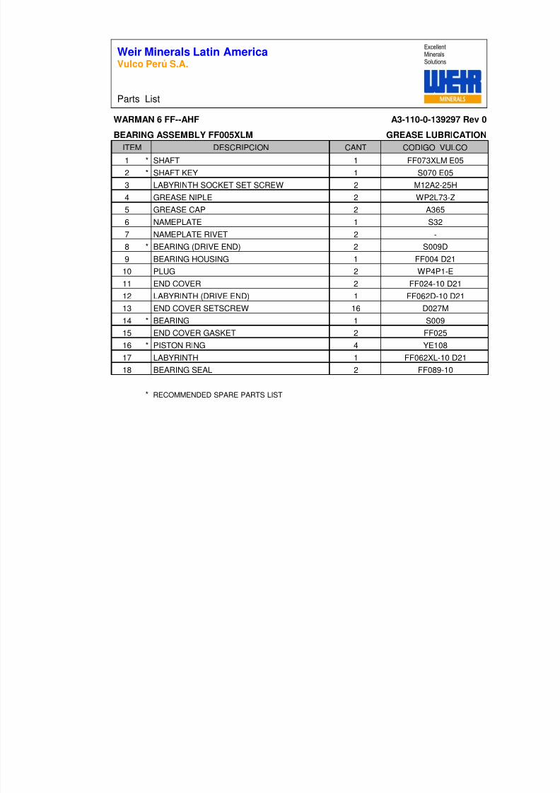
WARMAN 6 FF--AHF A3-110-0-139297 Rev 0
BEARING ASSEMBLY FF005XLM GREASE LUBRICATION
DESCRIPCION CANT CODIGO VULCO
1 * SHAFT 1 FF073XLM E052 * SHAFT KEY 1 S070 E053 LABYRINTH SOCKET SET SCREW 2 M12A2-25H4 GREASE NIPLE 2 WP2L73-Z5 GREASE CAP 2 A3656 NAMEPLATE 1 S327 NAMEPLATE RIVET 2 -8 * BEARING (DRIVE END) 2 S009D9 BEARING HOUSING 1 FF004 D21
10 PLUG 2 WP4P1-E11 END COVER 2 FF024-10 D2112 LABYRINTH (DRIVE END) 1 FF062D-10 D2113 END COVER SETSCREW 16 D027M14 * BEARING 1 S00915 END COVER GASKET 2 FF02516 * PISTON RING 4 YE10817 LABYRINTH 1 FF062XL-10 D2118 BEARING SEAL 2 FF089-10
* RECOMMENDED SPARE PARTS LIST
ITEM
Weir Minerals Latin AmericaVulco Perú S.A.
Parts List
ExcellentMineralsSolutions

8/15/2019 r1_OF 71289_6 FF-AHF
http://slidepdf.com/reader/full/r1of-712896-ff-ahf 9/333
© Weir Minerals Australia Ltd 2007. Weir Minerals Australia Ltd. is the owner of the Copyright in this document. The document and its text, images, diagrams, data andinformation it contains must not be copied or reproduced in whole or in part, in any form or by any means, without the prior written consent of Weir Minerals Australia Ltd.
Office of origin : Pump Technology Centre, Artarmon Reference : Pump Manuals
Date : 22 January 2007 Last Issued: July 2005
Assembly & MaintenanceInstructionsSupplement ‘M1’General Instruct ion
Applicable to all types of Warman Pumps

8/15/2019 r1_OF 71289_6 FF-AHF
http://slidepdf.com/reader/full/r1of-712896-ff-ahf 10/333
23/01/2007 © Copyright Weir Minerals Australia Ltd Page 2 of 34
Weir Minerals | M01 General Instructions for All Pumps Jan 07.doc
WarningsPersonnel injury and / or equipment damage could result from not observing the followingIMPORTANT SAFETY INFORMATION
. • A pump is both a pressure vessel and a piece of rotating equipment . All standard safetyprecautions for such equipment should be followed before and during installation, operation andmaintenance.
• For auxiliary equipment (motors, belt drives, couplings, gear reducers, variable speed drives,mechanical seals, etc) all related safety precautions should be followed and appropriateinstruction manuals consulted before and during installation, operation, adjustment andmaintenance.
• All guards for rotating equipment must be correctly fitted before operating the pump includingguards temporarily removed for gland inspection and adjustment. Seal guards should not be
removed or opened while the pump is running. Personal injury may result from contact withrotating parts, seal leakage or spray.•
Driver rotation must be checked before belts or couplings are connected.•
Pumps must not be operated at low or zero flow conditions for prolonged periods, or underany circumstances that could cause the pumping liquid to vaporise. Personnel injury andequipment damage could result from the high temperature and pressure created.
• Pumps must be used only within their allowable limits of pressure, temperature and speed.These limits are dependent on the pump type, configuration and materials used.
• Do not apply heat to t he impeller boss or nose in an effort to loosen the impeller thread priorto impeller removal. Personnel injury and equipment damage could result from the impellershattering or exploding when the heat is applied.
• Do not feed very hot or very cold liquid into a pump which is at ambient temperature.Thermal shock may cause the pump casing to crack.
• LIFTING of components
• Tapped holes (for eye bolts) and lugs (for lifting shackles) on Warman pumps are forlifting Individual parts only .
• Lifting devices of adequate capacity must be used wherever they are required to beused.
• Safe workshop practices should be applied during all assembly and maintenance work.• Personnel must never work under suspended loads.
• The pump must be fully isolated before any maintenance work, inspection or troubleshootinginvolving work on sections which are potentially pressurised (eg casing, gland, connectedpipework) or involving work on the mechanical drive system (eg shaft, bearing assembly,coupling). Power to the electric motor must be isolated and tagged out. It must be proven thatthe intake and discharge openings are totally isolated from all potentially pressurisedconnections and that they are and can only be exposed to atmospheric pressure.
•

8/15/2019 r1_OF 71289_6 FF-AHF
http://slidepdf.com/reader/full/r1of-712896-ff-ahf 11/333
23/01/2007 © Copyright Weir Minerals Australia Ltd Page 3 of 34
Weir Minerals | M01 General Instructions for All Pumps Jan 07.doc
Castings made from materials listed are brittle and have low thermal shock resistance. Attempts to repair or rebuild by welding may cause catastrophic failure. Repairs of suchcastings using these methods must not be attempted - A03, A04, A05, A06, A07, A08, A09,
A12, A14, A49, A51, A52, A53, A61, A210, A211, A217, A218, A509.•
Impellers must be tight on the shaft before any start-up, ie all components on the shaft betweenthe impeller and the pump end bearing must butt metal to metal against each other without anygap. Note that gaps may form when the pump experiences duty conditions conducive tounscrewing of the impeller, such as excessive runback, high intake pressure, motor braking etc.
• Burning of elastomer pump components will cause emission of toxic fumes and result in airpollution which could lead to personnel injury.
• Leakage from the pump shaft seals and/or leakage from worn pump components or seals maycause water and/or soil contamination.
• Liquid waste disposal from servicing of pumps or stagnant water from pumps stored for longperiods, may cause water and/or soil contamination.
• Do not apply anti-seize compounds to the impeller or shaft threads or to elastomer sealsduring assembly. Anti-seize can greatly reduce the impeller thread friction and may cause theimpeller to loosen during pump shut-down and run-back resulting in pump damage, or theelastomer seals to leak at reduced pressure.
• This manual applies only to genuine Warman parts and Warman recommended parts.
• Mixing of new and worn pump parts may increase the incidence of premature pump wear andleakage.
• Large foreign objects or tramp entering a pump will increase the incidence of higher wear and/ or damage to the pump. Routine inspection and maintenance of mill trommel screens willassist to reduce the danger of grinding balls entering a mill discharge pump.
• Large variations in slurry properties may lead to accelerated rates of wear and corrosion ofpump components eg• Wear increases exponentially with velocity and slurry particle size.• Corrosion rate doubles for every 10 degree Celsius increase in slurry temperature.• Corrosion rate increases exponentially as slurry pH decreases.

8/15/2019 r1_OF 71289_6 FF-AHF
http://slidepdf.com/reader/full/r1of-712896-ff-ahf 12/333
23/01/2007 © Copyright Weir Minerals Australia Ltd Page 4 of 34
Weir Minerals | M01 General Instructions for All Pumps Jan 07.doc
ISSUED: JANUARY 2007 LA ST ISSUE: JULY 2005
WARMAN PUMPS ASSEMBLY AND MAINTENANCE INSTRUCTIONS
SUPPLEMENT ‘M1’General Instruction
Applicable to all types ofWarman Pumps
CONTENTS
WARNINGS 2
CONTENTS 4
1 INTRODUCTION 6 GENERAL 6 PUMP IDENTIFICATION 6
2 FOUNDATIONS 8 SHAFT ALIGNMENT 8
ALIGNMENT, TENSIONING AND ADJUSTMENT OF VEE-BELT DRIVES 8
ALIGNMENT OF DIRECT COUPLED PUMPS 11
PIPEWORK 13 Flanges 13 Intake Conditions 13
3 OPERATION 14 GENERAL 14
SHAFT SEAL 14
SHAFT UNLOCKING 15
MOTOR ROTATION CHECK 15
PRIMING 15 NORMAL PUMP START UP 16
ABNORMAL START UP 17
Blocked Intake Pipe 17
Air Entering Gland 17
OPERATING FAULTS 17
Low Pit Level 17

8/15/2019 r1_OF 71289_6 FF-AHF
http://slidepdf.com/reader/full/r1of-712896-ff-ahf 13/333
23/01/2007 © Copyright Weir Minerals Australia Ltd Page 5 of 34
Weir Minerals | M01 General Instructions for All Pumps Jan 07.doc
Blocked Intake Pipe 18
Blocked Impeller 18
Blocked Discharge Pipe 18
SHUTTING DOWN PROCEDURE 18
4 MAINTENANCE 19 RUNNING MAINTENANCE 19
General 19
Shaft Seal Care 19
Repacking Gland 20
Impeller Adjustment 20
Tightening Down 21
Labyrinth Grease Purging 21
Bearing Lubrication 21
OVERHAUL MAINTENANCE 22
General 22
Pump Dismantling 22
Inspection & Removal of Bearings 23
Replacement of Wearing Parts 24
Reassembling Pump Overhaul 25
5 COMMISSIONING OF PUMPS 26 STORAGE OF PUMPS & STAND BY PUMPS 26
SPARE PARTS 26
6 APPENDIX A 31 SEAL TYPES, PROBLEMS AND SOLUTIONS 31
8/15/2019 r1_OF 71289_6 FF-AHF
http://slidepdf.com/reader/full/r1of-712896-ff-ahf 14/333
23/01/2007 © Copyright Weir Minerals Australia Ltd Page 6 of 34
Weir Minerals | M01 General Instructions for All Pumps Jan 07.doc
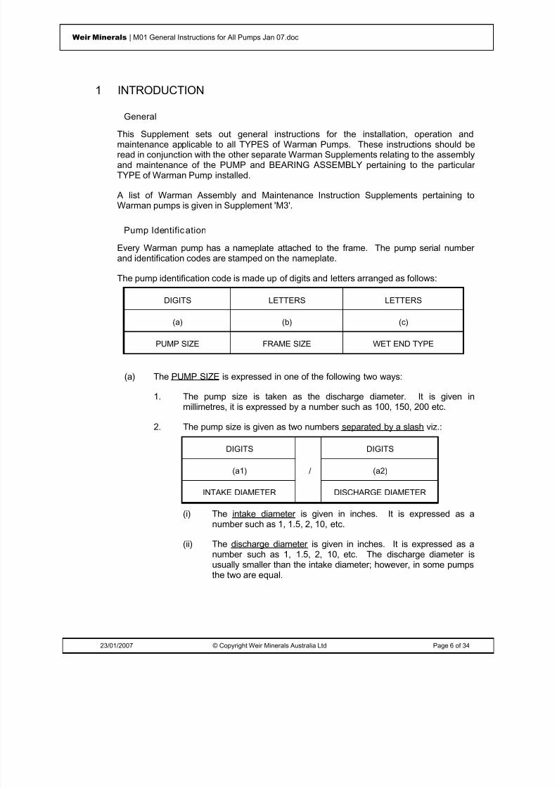
1 INTRODUCTION
General
This Supplement sets out general instructions for the installation, operation andmaintenance applicable to all TYPES of Warman Pumps. These instructions should beread in conjunction with the other separate Warman Supplements relating to the assemblyand maintenance of the PUMP and BEARING ASSEMBLY pertaining to the particularTYPE of Warman Pump installed.
A list of Warman Assembly and Maintenance Instruction Supplements pertaining toWarman pumps is given in Supplement 'M3'.
Pump Identific ation
Every Warman pump has a nameplate attached to the frame. The pump serial numberand identification codes are stamped on the nameplate.
The pump identification code is made up of digits and letters arranged as follows:
DIGITS LETTERS LETTERS
(a) (b) (c)
PUMP SIZE FRAME SIZE WET END TYPE
(a) The PUMP SIZE is expressed in one of the following two ways:
1. The pump size is taken as the discharge diameter. It is given inmillimetres, it is expressed by a number such as 100, 150, 200 etc.
2. The pump size is given as two numbers separated by a slash viz.:
DIGITS DIGITS
(a1) / (a2)
INTAKE DIAMETER DISCHARGE DIAMETER
(i) The intake diameter is given in inches. It is expressed as a
number such as 1, 1.5, 2, 10, etc.(ii) The discharge diameter is given in inches. It is expressed as a
number such as 1, 1.5, 2, 10, etc. The discharge diameter isusually smaller than the intake diameter; however, in some pumpsthe two are equal.
8/15/2019 r1_OF 71289_6 FF-AHF
http://slidepdf.com/reader/full/r1of-712896-ff-ahf 15/333
23/01/2007 © Copyright Weir Minerals Australia Ltd Page 7 of 34
Weir Minerals | M01 General Instructions for All Pumps Jan 07.doc
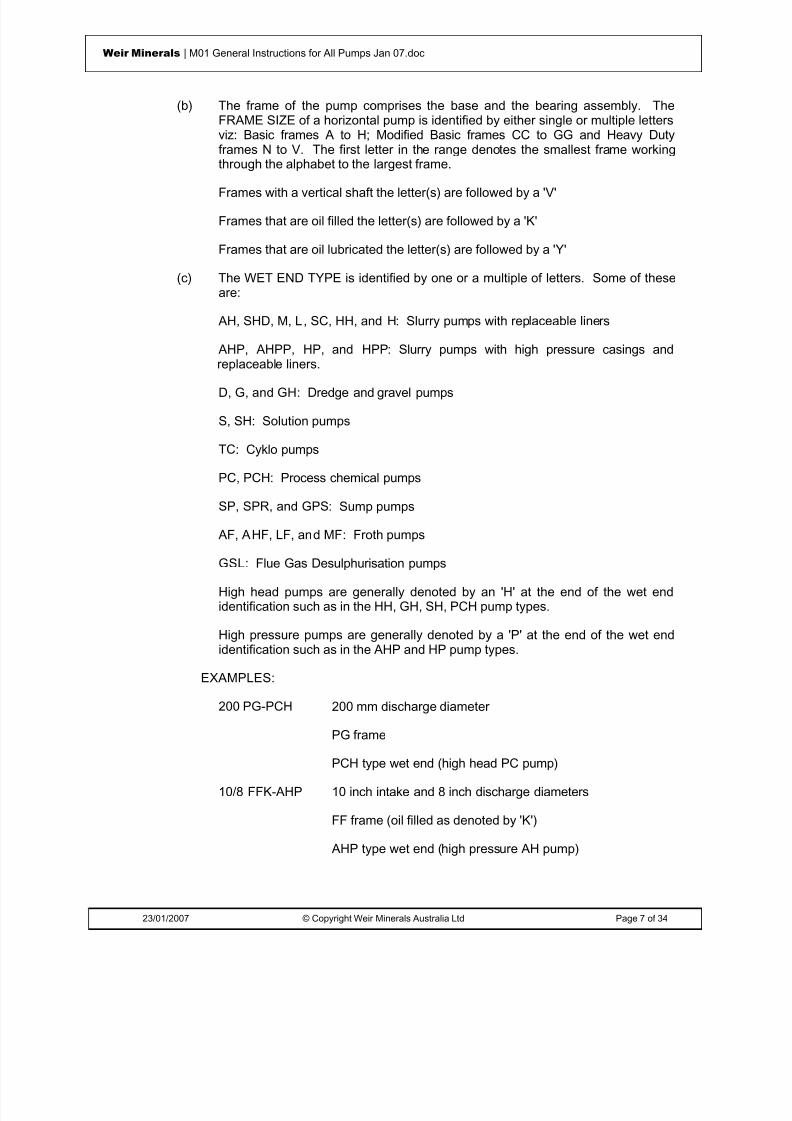
(b) The frame of the pump comprises the base and the bearing assembly. TheFRAME SIZE of a horizontal pump is identified by either single or multiple lettersviz: Basic frames A to H; Modified Basic frames CC to GG and Heavy Dutyframes N to V. The first letter in the range denotes the smallest frame workingthrough the alphabet to the largest frame.
Frames with a vertical shaft the letter(s) are followed by a 'V'
Frames that are oil filled the letter(s) are followed by a 'K'
Frames that are oil lubricated the letter(s) are followed by a 'Y'
(c) The WET END TYPE is identified by one or a multiple of letters. Some of theseare:
AH, SHD, M, L , SC, HH, and H : Slurry pumps with replaceable liners
AHP, AHPP, HP, and HPP : Slurry pumps with high pressure casings andreplaceable liners.
D, G, and GH : Dredge and gravel pumps
S, SH : Solution pumps
TC : Cyklo pumps
PC, PCH : Process chemical pumps
SP, SPR, and GPS : Sump pumps
AF, AHF, LF, and MF : Froth pumps
GSL: Flue Gas Desulphurisation pumps
High head pumps are generally denoted by an 'H' at the end of the wet endidentification such as in the HH, GH, SH, PCH pump types.
High pressure pumps are generally denoted by a 'P' at the end of the wet endidentification such as in the AHP and HP pump types.
EXAMPLES:
200 PG-PCH 200 mm discharge diameter
PG frame
PCH type wet end (high head PC pump)
10/8 FFK-AHP 10 inch intake and 8 inch discharge diameters
FF frame (oil filled as denoted by 'K')
AHP type wet end (high pressure AH pump)

8/15/2019 r1_OF 71289_6 FF-AHF
http://slidepdf.com/reader/full/r1of-712896-ff-ahf 16/333
23/01/2007 © Copyright Weir Minerals Australia Ltd Page 8 of 34
Weir Minerals | M01 General Instructions for All Pumps Jan 07.doc
2 FOUNDATIONSEfficient pump service can be obtained only by installing the pump on adequatefoundations. Steel foundations should be robust, concrete foundations heavy. Bothshould be designed to take all loads from the pump and motor and to absorb anyvibrations. All holding down bolts should be fully tightened.
The pump should be located such that the length of the intake pipe is as short as possible. Adequate space to provide access for installation and dismantling to replace worncomponents should be allowed.
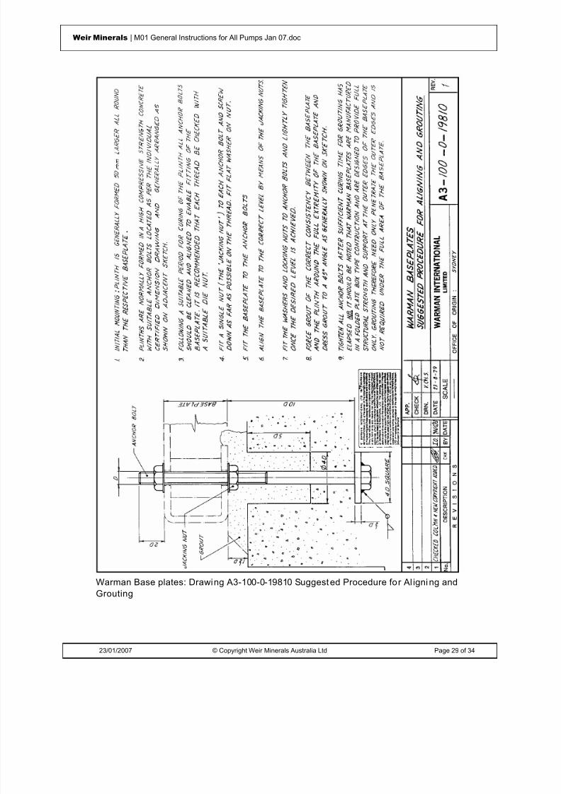
A suggested procedure for aligning and grouting Warman Base plates is given onWarman Drawing A3-100-0-19810 attached.
Where a pump base is mounted directly onto a steel framework this should be designedwith sufficient strength to withstand normal pumping operational stress and to ensure thatthere is no distortion to the base frame when the pump and pump base are installed.
Shaft AlignmentWhether direct coupled or vee-belt driven, the pump and motor shafts should beaccurately aligned. In direct coupled drives, misalignment causes unnecessary vibrationand wear of the coupling. In vee-belt drives, non-parallel shafts cause excessive beltwear. Rigid couplings must be avoided.
It should be noted that pump sets which have been accurately aligned in the factory canbecome misaligned during transportation so alignment must be rechecked duringinstallation.
Vee-belt and flexible transmissions should be aligned (and tensioned) in accordance withthe suggested recommendations below.
Direct coupling large pumps to diesel prime movers must also be avoided as suddenstoppage of the diesel can cause unscrewing of the pump impeller and consequent pumpdamage. A clutch or fluid coupling fitted between the pump and diesel prime mover isrecommended.
Al ignment , Tens ioning and Adjustment of Vee-Belt Drives
For optimum performance of Vee-Belts, only new matched sets of belts should be used(belts should lie within a range of 2 to 4 set numbers according to the belt length). Alwaysplace belts with the lowest code numbers closest to the bearings.
Clean any oil or grease from the pulleys and remove any burrs and rust from the grooves
before fitting belts. ALIGNMENT: Good alignment of pulleys is important; otherwise the belt flanks will wearquickly.
Reduce the centre distance by jacking the motor towards the pump using the jacking boltssupplied, until the belts can be put onto the pulley grooves without forcing.

8/15/2019 r1_OF 71289_6 FF-AHF
http://slidepdf.com/reader/full/r1of-712896-ff-ahf 17/333
23/01/2007 © Copyright Weir Minerals Australia Ltd Page 9 of 34
Weir Minerals | M01 General Instructions for All Pumps Jan 07.doc
Use a good straight edge across both motor and pump pulley faces. It is important toalign the two pulleys to a tolerance whereby daylight is non existent or at a minimumbetween the pulleys and the straight edge.
WARNING
AFTER PUMP IMPELLER ADJUSTMENTS RECHECK THE PULLEY ALIGNMENT AND ADJUST AS NECESSARY BEFORE RESTARTING THE PUMP
TENSIONING:
Proper tensioning of the belts ensures a longer life both for the belts and the rollerbearings.
The high performance required from modern belts cannot be achieved without correcttensioning. To check the belt for correct tensioning refer to figure below and proceed asfollows:
(a) Measure the length of span(b) Apply a force at right angles to the belt at the centre of the span sufficient to deflect
one belt by 16 mm per metre of span
(c) Compare the force required with the value stated in the table.
If the measured force is within the values stated in the table the belt tensioning should besatisfactory. If the force measured is below or above the value stated, the belt should betightened or slackened respectively. Provision should be made for periodic checking ofbelt wear during the life of a belt and adjusting the belts to correct tension as necessary.
NOTE : New belts should be tensioned at the higher level stated (using a Vee-Belt TensionIndicator) to allow for a drop in tension during the normal running in period. New beltsshould be run under load for two hours, stopped, and the tension re-checked, re-setting the adjustment to achieve the correct tension as necessary. During the first24 hours running, it is recommended that a further check is carried out and the beltsadjusted as required.
Under tensioning: Under tensioning of the drive can cause vibration resulting in damageto the bearing cartridge, as well as the loss of transmission efficiency. It can also causethe belts to slip and overheat, resulting in belt fatigue and subsequently a shortening ofthe belt life.
Over tensioning: Over tensioning belts also shortens their life. Furthermore, bearingswill tend to overheat due to excessive radial forces on the rolling elements and this will
lead to premature bearing failure. ADJUSTMENT
After new belts have been fitted or a new installation has been completed, when the drivehas been running for approximately 2 hours the tension of the belts should be re-checkedand re-adjusted. The drive should be subsequently checked at regular maintenanceintervals.

8/15/2019 r1_OF 71289_6 FF-AHF
http://slidepdf.com/reader/full/r1of-712896-ff-ahf 18/333
23/01/2007 © Copyright Weir Minerals Australia Ltd Page 10 of 34
Weir Minerals | M01 General Instructions for All Pumps Jan 07.doc
Belt SectionSmall Pulley
Diameter (mm)
Force required to deflect belt 16mmper metre of span;
Newton (N)
SPZ 56 to 95 13 to 20 100 to 140 20 to 25
SPA 80 to 132 25 to 35 140 to 200 35 to 45
SPB 112 to 224 45 to 65 236 to 315 65 to 85
SPC 224 to 355 85 to 115 375 to 560 115 to 150
A 80 to 140 10 to 15
B 125 to 200 20 to 30
C 200 to 400 40 to 60
Figure 1: Alignment, Tensioni ng and adjustment of Vee-Belt
16mm deflectionper metre of span
span
Force

8/15/2019 r1_OF 71289_6 FF-AHF
http://slidepdf.com/reader/full/r1of-712896-ff-ahf 19/333
23/01/2007 © Copyright Weir Minerals Australia Ltd Page 11 of 34
Weir Minerals | M01 General Instructions for All Pumps Jan 07.doc
Al ignment of Direct Coupled Pumps
In a direct coupled drive, misalignment causes unnecessary vibration and wear on thebearings. Rigid couplings (ie couplings that bolt directly together without any flexiblemember in between) should be avoided and must not be used without consultation withWeir Minerals Division.
The following procedures outline a suggested practice for checking shaft alignment. Thismethod is independent of the truth of the coupling or shaft and is therefore not affected bycanted coupling faces or eccentricity of the outside diameter of the coupling.
CAUTION
CHECK THAT NO DAMAGE CAN BE CAUSED WHEN THE SHAFT OF THE DRIVENUNIT IS TURNED
Before commencing alignment rotate each shaft independently to check that the shaft andbearings turn without undue friction and that the shaft is true to within 0.04 mm or betteras measured on a Dial Indicator (DI).
Couplings should be loosely coupled, each half must be free to move relative to the otheror the resulting Dial Indicator readings can be incorrect. Where tightly fitting pins orsprings prevent loose coupling, the pins or springs should be removed, a line scribedacross both half couplings and the readings taken only when the two are aligned. Oncouplings with a serrated rim, ensure that as the couplings are rotated, the gaugeplungers do not fall into a groove and become damaged.
Angular shaft alignment : To ensure correct angular shaft alignment proceed as follows:
(a) Isolate the driving unit from the power supply.(b) Refer to the left hand figure below and clamp two Dial Indicators (DI) at diametrically
opposite points (180°) on one half coupling, with the plungers resting on the back ofthe other half coupling.
(c) Rotate the couplings until the gauges are in line vertically, and set the gauges toread zero.
(d) Rotate the couplings through half a revolution (180°) and record the reading on eachDI. The readings should be identical though not necessarily zero because ofpossible end float. Either positive or negative readings are acceptable provided theyare equally positive or equally negative. Refer to the paragraphs below headed
"Tolerances" for the maximum allowable tolerance and adjust the position of one ofthe units if necessary.
(e) Rotate the couplings until the gauges are in line horizontally and reset the gauges toread zero.
(f) Repeat operation (d) and adjust the unit position until the correct tolerance isachieved and no further adjustment is necessary.

8/15/2019 r1_OF 71289_6 FF-AHF
http://slidepdf.com/reader/full/r1of-712896-ff-ahf 20/333
23/01/2007 © Copyright Weir Minerals Australia Ltd Page 12 of 34
Weir Minerals | M01 General Instructions for All Pumps Jan 07.doc
Radial shaft alignment: To ensure that radial shaft alignment is correct proceed asfollows:
(a) Clamp a DI to one half coupling or to the shaft, as shown in right hand portion offigure below, with the plunger resting on the rim of the other half coupling.
(b) Set the gauge to read zero.
(c) Rotate the couplings and note the reading at each quarter revolution (90°). Anyvariation in the readings indicates a deviation from alignment and the position of oneof the units must be adjusted until the readings at each quarter revolution areidentical or within the tolerances given. Refer to paragraphs below headed"Tolerances".
NOTE : Provisional alignment can be carried out with the unit cold; however, where theworking temperature of the pump has the effect of raising the centre line of onemachine relative to the other allowances must be made. The units should thenbe realigned when each have attained their correct operating temperature.
Tolerances: Follow the manufacturer’s recommendation. If no recommendation isavailable the limits of accuracy within which adjustments must be made cannot bespecifically defined because of differences in the size of and speed of units. However, thefollowing variations which can be tolerated when checking alignment and are suggestedas a general guidance.
1. Angular Alignment:
Couplings up to 300 mm diameter 0.05 mmCouplings more than 300 mm diameter 0.07 mm
Figure 2: Alignment of Direct Coupled Pumps

8/15/2019 r1_OF 71289_6 FF-AHF
http://slidepdf.com/reader/full/r1of-712896-ff-ahf 21/333
23/01/2007 © Copyright Weir Minerals Australia Ltd Page 13 of 34
Weir Minerals | M01 General Instructions for All Pumps Jan 07.doc
2. Radial Alignment:
Not to exceed 0.1 mm on Dial Indicator (ie 0.05 mm eccentricity)Figure 2: Alignment of Direct Coupled Pumps
Pipework
Pipelines and valves should be properly aligned with pump flanges and they should besupported independently of the pump. All pipe design should be on the basis of zeropump flange loading - if this condition cannot be achieved then values for the maximumallowable external loads and moments on the pump flanges is available from WeirMinerals Division.
APPROPRIATE WARMAN JOINT RINGS (when required) MUST BE USED AT THEPUMP FLANGES. THE JOINT RINGS FORM AN EFFECTIVE SEAL BETWEENPIPEWORK AND PUMP CASING. In some pumps, the metal liner projects a shortdistance past the flange. Care should be taken in such instances not to over tighten the
flange bolts so as not to damage the joint rings. A removable piece of pipe should be used on the intake side of the pump. This pipeshould be of sufficient length to allow removal of the pump cover plate or casing and toenable access to pump wearing parts and impeller.
Removal of the intake pipe is facilitated if a flexible joint is used in place of the flangedconnection. All pipe joints must be airtight to ensure priming of the pump.
Recommendations and procedures for inter-stage piping for multi-stage installations areavailable from Weir Minerals Division.
Flanges
Matching flanges on the pump intake and discharge must be flush as shown on attacheddrawing A4-111-1-121595. Keeping flanges flush is important in providing proper backupsupport and compression for intake and discharge joint rings to prevent leakage.
Warman Intake and Discharge slip-on matching flanges can be supplied on request.
Intake Conditi ons
Suitable isolation should be fitted in the intake pipe as near to the pump as possible. Theintake pipe should be as short as possible. An arrangement of intake pipework which iscommon to two or more pumps operating on suction lift is not recommended. If such anarrangement is unavoidable any points of possible air ingress, such as valve glandsshould be liquid sealed and isolating valves should be fitted at appropriate points.
The diameter of the intake pipe required depends upon its length and bears no fixedrelationship to the diameter of the intake branch of the pump. The size of the pipe mustbe such that the velocity is kept to a minimum, but above the solids particle critical settlingvelocity to reduce friction losses, i.e. a long intake pipe, (or one with numerous bends)which passes a given quantity or liquid must be of larger bore than a short straight onepassing the same quantity of liquid.
8/15/2019 r1_OF 71289_6 FF-AHF
http://slidepdf.com/reader/full/r1of-712896-ff-ahf 22/333
23/01/2007 © Copyright Weir Minerals Australia Ltd Page 14 of 34
Weir Minerals | M01 General Instructions for All Pumps Jan 07.doc
When the bore of the intake pipe is increased to a size larger than that of the pump intakebranch, the form of taper pipe used must not allow the formation of air pockets. To avoidair pockets, the installation of intake pipework must be arranged with as few bends aspossible and the pipework must be completely airtight.
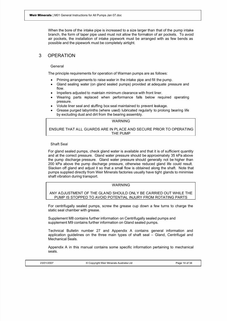
3 OPERATION
General
The principle requirements for operation of Warman pumps are as follows:• Priming arrangements to raise water in the intake pipe and fill the pump.• Gland sealing water (on gland sealed pumps) provided at adequate pressure and
flow.• Impellers adjusted to maintain minimum clearance with front liner.• Wearing parts replaced when performance falls below required operating
pressure.•
Volute liner seal and stuffing box seal maintained to prevent leakage.• Grease purged labyrinths (where used) lubricated regularly to prolong bearing lifeby excluding dust and dirt from the bearing assembly.
WARNING
ENSURE THAT ALL GUARDS ARE IN PLACE AND SECURE PRIOR TO OPERATINGTHE PUMP
Shaft Seal
For gland sealed pumps, check gland water is available and that it is of sufficient quantityand at the correct pressure. Gland water pressure should be approximately 35 kPa above
the pump discharge pressure. Gland water pressure should generally not be higher than200 kPa above the pump discharge pressure, otherwise reduced gland life could result.Slacken off gland and adjust it so that a small flow is obtained along the shaft. Note thatpumps supplied directly from Weir Minerals factories usually have tight glands to minimiseshaft vibration during transport.
WARNING
ANY ADJUSTMENT OF THE GLAND SHOULD ONLY BE CARRIED OUT WHILE THEPUMP IS STOPPED TO AVOID POTENTIAL INJURY FROM ROTATING PARTS
For centrifugally sealed pumps, screw the grease cup down a few turns to charge thestatic seal chamber with grease.
Supplement M8 contains further information on Centrifugally sealed pumps andsupplement M9 contains further information on Gland sealed pumps.
Technical Bulletin number 27 and Appendix A contains general information andapplication guidelines on the three main types of shaft seal – Gland, Centrifugal andMechanical Seals.
Appendix A in this manual contains some specific information pertaining to mechanicalseals.

8/15/2019 r1_OF 71289_6 FF-AHF
http://slidepdf.com/reader/full/r1of-712896-ff-ahf 23/333
23/01/2007 © Copyright Weir Minerals Australia Ltd Page 15 of 34
Weir Minerals | M01 General Instructions for All Pumps Jan 07.doc
WARNING
REMOVE THE MECHANICAL SEAL SETTING TABS AND TORQUE THE LOCKINGCOLLAR FASTENERS TO THE SPECIFIED VALUES PRIOR TO STARTING THE
PUMP, OTHERWISE SERIOUS SEAL AND PUMP DAMAGE COULD RESULT
Shaft Unlocking
For transport of Warman pumps the bearings can be locked to prevent vibration andconsequent damage. Note that it is not absolutely critical to lock the bearings as smallmovements help to prevent false brinelling. Clamping is done by attaching the shaftclamp to the shaft. A set screw in the handle of the clamp is then screwed up hard
against the pump base to lock the bearings. Alternatively, the pump is supplied with thevee-belts tensioned to reduce shaft movement.
Before use of the pump, the set screw must be removed to free the bearings oralternatively the vee-belt tension must be checked and adjusted if necessary. The shaftshould then be rotated by hand (clockwise) by means of the clamp to ensure that theimpeller turns freely within the pump. At any sign of scraping noises from the pump, theimpeller must be adjusted (see Assembly and Maintenance Instructions for the particularTYPE of Warman pump). The shaft clamp must then be removed.
Motor Rotation Check
Remove all vee-belts or completely disconnect shaft coupling, as the case may be. THIS
IS IMPORTANT!
Start motor, check rotation and correct it if necessary to produce pump shaft rotationindicated by arrow on the pump casing. Refit vee-belts or reconnect shaft coupling.When tensioning belts maintain shaft alignment and check belt tension.
WARNINGROTATION IN DIRECTION OPPOSITE TO THE ARROW THE PUMP WILL UNSCREW
THE IMPELLER FROM THE SHAFT CAUSING SERIOUS DAMAGE TO THE PUMP
Priming
Arrangements for raising water in the intake pipe and filling the pump (or first stage of a
multi-stage installation) must be provided in preparation to starting up. Gland sealingwater should then be turned on to the pump(s). To ensure trouble free operation ofglands the gland sealing water pressures should be approximately 35 kPa higher then thepumps operating discharge pressure.
IMPORTANT NOTE: Gland sealing water must be left on during all subsequentoperations, namely, start up, running, shut down and run back. Gland water may beturned off only after shut down and then only after all the slurry in the pipeline hasdrained back to the pit.

8/15/2019 r1_OF 71289_6 FF-AHF
http://slidepdf.com/reader/full/r1of-712896-ff-ahf 24/333
23/01/2007 © Copyright Weir Minerals Australia Ltd Page 16 of 34
Weir Minerals | M01 General Instructions for All Pumps Jan 07.doc
Normal Pump Start Up
Check once more that all bolts are tight and that the impeller turns freely. Ensure thatshaft seal is in order and that pressure of gland water supply, where used, is correct.
It is good practice whenever possible to start up pumps on water before introducing solidsor slurry into the stream. On shutting down it is also desirable that pumps should beallowed to pump water only for a short period before shut down.
Open intake valve (if any) and check that water is available at the inlet. Check drain valve(if any) is closed.
If a discharge valve is installed it is common practice to close it for start up. This ishowever mandatory only in some special cases where the motor could overload.
Start pump and run up to speed, if pump is on suction lift execute priming procedure forfacilities provided. When the pump is primed, isolate prime facilities (if any). Opendischarge valve. Check intake and discharge pressures (if gauges have been provided).Check flow rate by inspection of meters or pipe discharge.
Check Gland leakage. If leakage is excessive tighten gland nuts until flow is reduced tothe required level. If leakage is insufficient and gland shows signs of heating, then tryloosening gland nuts. If this is ineffective and the gland continues to heat up, the pumpshould be stopped and the gland allowed to cool. Gland nuts should not be loosened tosuch an extent that the gland follower is allowed to disengage the stuffing box.
WARNING
ANY ADJUSTMENT OF THE GLAND SHOULD ONLY BE CARRIED OUT WHILE THEPUMP IS STOPPED TO AVOID POTENTIAL INJURY FROM ROTATING PARTS
NOTE It is normal for gland leakage water to be hotter than the supply because it isconducting away the heat generated by friction in the gland.
At low pressures (single stage operation) very little leakage is required and it is possible tooperate with only a small amount of water issuing from the gland. It is not essential tostop a pump because of gland heating unless steam or smoke is produced.
This difficulty is normally only experienced on initial start up on gland sealed pumps.When initial heat up of the gland is encountered, it is only necessary to start up -- stop --cool and start the pump two or three times before the packing beds in correctly and thegland operates satisfactorily.
It is preferable at start to have too much leakage than not enough.
After the pump has run for 8-10 hours, gland bolts can be adjusted to give optimumleakage. If heating of gland persists, the packing should be removed and the glandrepacked.
Warman pumps are normally packed with non-asbestos packing, Warman material codeQ05, for general duties and pressures up to 2000 kPa. Above 2000 kPa it is usuallynecessary to use an anti-extrusion ring between the gland follower and the last ring ofpacking. High pressure packing recommendations are available from Weir MineralsDivision.

8/15/2019 r1_OF 71289_6 FF-AHF
http://slidepdf.com/reader/full/r1of-712896-ff-ahf 25/333
23/01/2007 © Copyright Weir Minerals Australia Ltd Page 17 of 34
Weir Minerals | M01 General Instructions for All Pumps Jan 07.doc
For multi-stage installations it is usually necessary to time the starting of the second andsubsequent stage pumps to prevent motor overload. Recommendations and proceduresfor start up are available from Weir Minerals Division.
Abnormal Start Up
If the pump fails to prime, one or more of the following faults may be the cause:
Blocked Intake Pipe
When the pump has not been operated for some time, it is possible for slurry to settle inthe intake pipe or around it if operating from a pit and thereby prevent water rising to thepump impeller. The pressure gauge on the intake side of the pump may be used to checkthe level of water in the pump.
Ai r Entering Gland
If one of the following conditions applies, air may be induced into the pump through thegland. This may prevent the pump "picking up" its prime or cause it to loss its primeduring operation.
• Sealing water pressure too low• Packing is excessively worn• Shaft sleeve is excessively worn• Gland sealing water connection into stuffing box is blocked.
Inspection of the gland will readily reveal if above faults are occurring and remedial actionis self evident.
Operating Faults
Refer to the FAULT FINDING CHART at the back of this Supplement to determine themost likely cause of any problems. Some of the major faults that can occur are more fullydetailed below.
Overloading can occur when the pump is discharging into an empty system when thedelivery head will be temporarily lower and the throughput in excess of that for which thepump is designed. Careful regulation of the delivery valve until the system is fully chargedwill prevent this.
WARNING
PUMPS THAT ARE NOT FITTED WITH A LEAK-OFF DEVICE MUST NOT BE RUNFOR A LONG PERIOD AGAINST A CLOSED DISCHARGE VALVE
Low Pit Level
Pumps (or first stage pumps in a multi-stage installation) may lose their prime if air isinduced through the gland. Pumps may also lose their prime if the water level in the pitfalls sufficiently low to allow air to be induced into the pump intake by vortex action.
In order to obtain the best possible pump operation, sump (or hopper) makeup watercontrols should be arranged to maintain as high a level in the sump (or hopper) as

8/15/2019 r1_OF 71289_6 FF-AHF
http://slidepdf.com/reader/full/r1of-712896-ff-ahf 26/333
23/01/2007 © Copyright Weir Minerals Australia Ltd Page 18 of 34
Weir Minerals | M01 General Instructions for All Pumps Jan 07.doc
runback requirements will allow and should be arranged to maintain this level within asclose limits as is practical.
Blocked Intake Pipe
It is possible during operation of pump for a piece of foreign material to be drawn acrossthe bottom of the intake pipe and thereby cause a partial obstruction. Such an obstructionmay not be sufficient to stop operation completely but will result in a reduced output fromthe pump. It will also cause a drop in discharge pressure and amps, and will increase thevacuum reading on the pump intake. Rough running and vibration of the pump may alsooccur due to the high induced suction causing cavitation within the pump.
Blocked Impeller
Impellers are capable of passing a certain size particle. If a particle larger in size entersthe intake pipe it may become lodged in the eye of the impeller thereby restricting theoutput of the pump. Such an obstruction will usually result in a drop of amps and a drop inboth discharge pressure and intake vacuum readings. Pump vibrations will also occur
due to the out of balance effects.
WARNING
BEFORE APPLYING MANUAL TORQUE TO THE PUMP SHAFT ENSURE THAT THEINTAKE AND DISCHARGE LINES ARE ISOLATED AND THAT THE MOTOR IS
DISCONNECTED
Blocked Discharge Pipe
Blocked discharge pipe may be caused by abnormally high concentration of coarseparticles in the pump discharge pipe or by the velocity in the discharge pipe being too lowto adequately transport the solids. Such a blockage will be shown up by a rise indischarge pressure and a drop in amps and intake vacuum readings.
Shutting Down Procedure
Whenever possible, the pump should be allowed to operate on water only for a shortperiod to clear any slurry through the system before shut down.
1. Close the discharge valve (if fitted) to reduce load on driving unit2. Shut down the pump3. Shut intake valve (if any)4. If possible flush pump with clean water and let it discharge through the drain valve.5. Gland sealing water (if any) must be left on during all subsequent operations,
namely: Start up, running, shut down and run back.Gland water may only then be turned off.

8/15/2019 r1_OF 71289_6 FF-AHF
http://slidepdf.com/reader/full/r1of-712896-ff-ahf 27/333
23/01/2007 © Copyright Weir Minerals Australia Ltd Page 19 of 34
Weir Minerals | M01 General Instructions for All Pumps Jan 07.doc
4 MAINTENANCE
Running Maintenance
General
Warman pumps are of robust construction and when correctly assembled and installed,they will give long trouble-free service with a minimum amount of maintenance.
The only maintenance required for pumps is as follows:• Gland adjustment• Gland re-packing• Impeller adjustment• Tightening down• Possible periodic greasing of Bearings
Shaft Seal Care
Gland
The gland sealing water supply should be steady as pressure fluctuations will make glandadjustment for optimum performance difficult.
Glands must be adjusted to provide reasonable leakage when seal water pressure is at aminimum and therefore when this pressure rises leakage will necessarily be excessive. Ifglands are adjusted to provide optimum leakage at the higher seal water pressures,insufficient lubrication will be obtained when this pressure falls.
The gland sealing water should be as clean as possible as even small amounts of solidscan quickly wear gland components. Refer to recommendations of gland water quality inthe respective Gland Maintenance Manuals.
Requirements for gland operation on the first stage of a multi-stage installation aredifferent from the other stages.
For the second and succeeding stages the gland water is only required to flush slurryaway from the shaft sleeve and provide lubrication for the gland packing. Gland water forthe first stage pumps as well as carrying out the above functions must also pressurise thegland to prevent ingress of air when the pressure at the shaft falls below atmospheric.
Check periodically gland seal water supply and discharge. Always maintain a very smallamount of clean water leakage along the shaft by regularly adjusting the gland. Whengland adjustment is no longer possible replace all packings with new ones.
Gland sealing water requirements can be reduced to a minimum using Warman Low FlowLantern Restrictors (Warman basic part Nº 118-1).

8/15/2019 r1_OF 71289_6 FF-AHF
http://slidepdf.com/reader/full/r1of-712896-ff-ahf 28/333
23/01/2007 © Copyright Weir Minerals Australia Ltd Page 20 of 34
Weir Minerals | M01 General Instructions for All Pumps Jan 07.doc
Centrifugal
In centrifugally sealed pumps lubricate the static seal chamber sparingly but regularly bymeans of the grease cup. Two turns of the grease cup per 12 hours running time isrecommended to form an adequate seal at the packing rings, to lubricate the glandpacking and to enable them to run in a dry condition. Use only recommended cleanlubricant.
Repacking Gland
When gland packing has deteriorated to such an extent that no further adjustment can beobtained by tightening down the gland follower, it is not good practice to attempt to correctthis by inserting one new ring of packing on top of the old rings.
When the gland follower has reached the limit of its travel all the old packing should beremoved from the gland and the gland repacked with new packing.
To repack a gland the gland bolts and gland clamp bolts should be taken out and the twohalves of the gland follower removed from the pump. Old packing may then be removedand the stuffing box recess cleaned out. It is not necessary to remove the lanternrestrictor during this operation. Rings of new packing should then be placed in positionand tamped home one ring at a time, making sure that the ends of each ring come hardtogether and joints in successive rings are staggered around the stuffing box.
Gland halves may then be replaced, secured with clamp bolts and nipped down with glandbolts. Nuts on gland bolts should then be slacked off and left finger tight until pump isstarted. After start-up glands maybe adjusted until leakage is at the required flow rate.
These glands are designed for water lubrication and some leakage is necessary duringoperation to lubricate and cool the packing and shaft sleeve. Gland leakage at all timesmust be clean and free from solids. If there is any sign of slurry leaking from a gland thenone of the following must be occurring:-
• Gland sealing water pressure is too low• Gland packing and/or shaft sleeve requires replacement• Gland sealing water connection to stuffing box is blocked
When a gland is being repacked during a complete pump overhaul it is easier to pack thestuffing box and assemble the gland while the stuffing box is out of the pump (refer toinstructions in the particular Warman Instruction Supplement depending on the TYPE ofpump).
The lantern restrictor, packing and gland maybe assembled into the stuffing box with theshaft sleeve in position in the stuffing box. The stuffing box, assembled gland and shaftsleeve may then be fitted to the pump as one unit.
Impeller Adjustment
Warman pump performance changes with the clearance existing between an openImpeller and the intake side liner. This is less pronounced with closed Impellers.
With wear, the clearance increases and the pump efficiency drops. For best performanceit is necessary, therefore, to stop the pump occasionally and move the impeller forward(this applies to metal, rubber and high efficiency style impellers). This adjustment can be

8/15/2019 r1_OF 71289_6 FF-AHF
http://slidepdf.com/reader/full/r1of-712896-ff-ahf 29/333
23/01/2007 © Copyright Weir Minerals Australia Ltd Page 21 of 34
Weir Minerals | M01 General Instructions for All Pumps Jan 07.doc
carried out in a few minutes without any dismantling. The correct setting of the impeller iswhen the clearance between the impeller and the intake side liner is a minimum.
WARNING
PRIOR TO IMPELLER ADJUSTMENT, THE MECHANICAL SEAL LOCK TABS MUSTBE INSTALLED AND THE LOCKING COLLAR RELEASED IN ORDER TO ALLOW
THE FREE MOVEMENT OF THE BEARING ASSEMBLY.
AFTER PUMP IMPELLER ADJUSTMENT, RECHECK THE PULLEY ALIGNMENT AND ADJUST AS NECESSARY AND RE-LOCK THE MECHANICAL SEAL LOCKING
COLLAR AND REMOVE THE LOCK TABS.
Tightening Down
Although Warman pump impellers are balanced before they leave the works, precisebalance cannot be achieved in operation because of uneven wear which can take place.Pumps are therefore subject to some vibration while running and this can result in
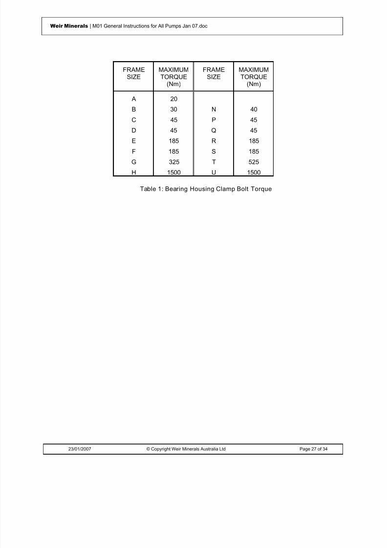
loosening of some bolts. It is recommended therefore that a routine maintenanceprogram be established whereby a check is made at regular intervals to ensure that allnuts are tight. To avoid any possible movement between the Bearing Assembly and theBase, the Bearing Housing Clamp Bolt must be maintained fully tightened. (See Table 1)
A convenient time for this check to be carried out would be at the same time as impelleradjustment is made. If any location is found where bolts consistently loosen then 'Nylock'nuts or other suitable locking devices should be fitted.
Labyrinth Grease Purging
To improve the sealing properties of the labyrinths on the end covers of some types ofWarman bearing assemblies, grease purging is utilised to purge out grit and moisture.Less contaminant entering the bearing assembly will result in longer bearing life andultimately cost savings. Therefore careful attention paid to labyrinth purging is anessential maintenance requirement.
Full details are given in the relevant Warman Bearing Assembly Instruction Supplement.
Bearing Lubrication
A correctly assembled and pre-greased bearing assembly will have a long trouble free life,provided it is protected against ingress of water or other foreign matter and that it isadequately maintained.
Suggested regreasing intervals are tabulated in the relevant “BA” maintenancesupplement depending on the type of bearing assembly in use.
It must be left to the good judgement of maintenance personnel, to open bearing housingsat regular intervals (not longer than twelve months) to inspect bearings and grease, todetermine the effectiveness of the re-lubrication program and to make any adjustments tothe program for the period up to the next inspection.
In the case of infrequent bearing regreasing being required, the bearing assembly greaseplug can be temporary replaced with grease nipples at the time of greasing.

8/15/2019 r1_OF 71289_6 FF-AHF
http://slidepdf.com/reader/full/r1of-712896-ff-ahf 30/333
23/01/2007 © Copyright Weir Minerals Australia Ltd Page 22 of 34
Weir Minerals | M01 General Instructions for All Pumps Jan 07.doc
If a regular addition of grease is judged to be necessary, then the plugs on the bearingassembly should be replaced with grease nipples. It is preferable to lubricate often andsparingly, than to add large amounts at long intervals. Bearings must never be overgreased.
Use only recommended, clean grease.
For oil lubricated bearings, it is recommended that a full oil change is carried out every 6months or 4,000 hours.
Additional information and recommendations on bearing lubrication intervals arecontained in the relevant Warman Bearing Assembly Instruction Supplements and in thefollowing sections 6.2.3 below.
Overhaul Maintenance
General
When the pump has worn to such an extent that the performance obtained no longer issatisfactory then the pump(s) should be dismantled for inspection and/or replacement ofwearing parts (impeller and liners).
If the bearing assembly requires maintenance, then the pump wet end must be dismantledbefore the bearing assembly can be removed from the pump.
NOTE: Bearing assemblies should only be reconditioned in a workshop preferably in aspecific area set aside for the work. A clean environment is essential.
Pump Dismantling
Isolate the pump from the system and wash down as much as possible. Remove drive
items as necessary after noting alignment of drive.
Dismantling can be done in situ if suitable lifting facilities and working space are availableotherwise the complete pump should be removed to a maintenance workshop.
NOTE:
(a) It is recommended that bearing assemblies should only be dismantled andoverhauled in the workshop.
(b) When bearing components are removed from a pump, they should be identifiedwith suitable tags so that if they are reused they may be replaced in the sameposition in the pump with their correct mating parts.
(c) Bearing components which are an interference fit on the shaft should beremoved only if replacement is necessary.
The procedure for removing the pump or bearing assembly is simply a reversal of theassembly procedure as set out in the relevant Instruction Supplements for the pump andbearing assembly.
Note that the pump must be dismantled before the bearing assembly can be removed forreconditioning.

8/15/2019 r1_OF 71289_6 FF-AHF
http://slidepdf.com/reader/full/r1of-712896-ff-ahf 31/333
23/01/2007 © Copyright Weir Minerals Australia Ltd Page 23 of 34
Weir Minerals | M01 General Instructions for All Pumps Jan 07.doc
All Warman pumps utilise a thread to fasten the impeller to the pump shaft. The largerpumps incorporate an impeller release collar to facilitate impeller removal. Full details canbe found in Warman Supplement 'M2'.
Inspection & Removal of Bearings
Since greasing requirements vary with operating conditions and environment the followinggeneral recommendations should be used as a guide.
When new bearings are fitted or re-assembled after overhaul they should be correctlypacked with grease. It is then recommended that a systematic program of investigationbe instituted in order to ascertain the following:
• whether the grease addition is required between overhauls• how frequently grease addition is required• what quantity of grease addition is required.
Proposals regarding the amount and frequency are given in the relevant manualSupplements depending on pump speed.
A suggested program of investigation is briefly described below for the case of a numberof the same pumps operating on similar or the same duties (i.e. the pumps have identicalbearings).
(a) Start with two pumps with bearings correctly packed with grease
(b) After a set number of hours (depending on the duty and environment) dismantlethe bearing assembly of one pump and inspect condition and disposition of thegrease
(c) From inspection assess whether grease addition is required at this interval and ifgrease addition is not required assess whether the second pump can safely run
to twice the set number of hours without greasing(d) By repeating this procedure on the remaining pumps in turn, the maximum time
interval before re-greasing may be determined and it may be found possible torun pumps for the life of the wearing parts without re-greasing bearings.
If these conditions can be achieved then bearing contamination is avoided and an overallsaving in labour effected.
It is recommended that a spare bearing assembly unit should be carried in store so thatthe assembly may be changed over when wearing parts are being replaced. Theassembly taken out may then be reconditioned in the workshop ready for installation in thenext drive assembly overhaul.
With correct care and maintenance, deterioration of bearings should be detected duringroutine overhauls before malfunctions become obvious in operation.
The criteria for examination of a bearing is contained in the question "Will the bearingoperate until the next overhaul?" Where there is any doubt regarding the condition of abearing it is far more economical to replace it while the pump is dismantled for overhaulthan to risk a failure in operation which may result in damage to other parts of the pump.

8/15/2019 r1_OF 71289_6 FF-AHF
http://slidepdf.com/reader/full/r1of-712896-ff-ahf 32/333
23/01/2007 © Copyright Weir Minerals Australia Ltd Page 24 of 34
Weir Minerals | M01 General Instructions for All Pumps Jan 07.doc
When to Remove Bearings
Bearings should be renewed when any of the following faults are observed:
(a) Face of race is worn to such an extent that a detectable shoulder is evident at theedge of the rolling track
(b) Cage is worn to such an extent that there is excessive slackness or burrs.
(c) Any roughness or pitting of rollers or rolling track.
The rolling track will often be slightly darker (stained) than the unused portion of the race.This does not mean that the bearing has reached the end of its useful life provided noother symptoms are present.
Removing Bearings
Care should be exercised during dismantling. When driving bearing cups out of theassembly with shaft and rollers, the shaft should be held hard in the direction of driving sothat rollers are seated hard up against the face of the cup and the effects of impact on thebearing faces are thereby minimised.
If inspection of bearings shows that they require replacement then a press or suitablepuller should be set up to bear on the end of the shaft and on the bearings.
When bearing components are removed from an assembly, they should be identified withsuitable tags so that if they are reused they maybe replaced in the same position in theassembly with their correct mating parts.
If any portion of a bearing required replacing then the bearing should be replaced in itsentirety. Worn parts must not be mixed with new parts. A complete new bearing at oneend of a bearing assembly may be installed with a used bearing at the other if required;however, if one bearing requires replacement, economics usually favour renewing thepair.
Replacement of Wearing Parts
The wear rate of a solids handling pump is a function of the severity of the pumping dutyand of the abrasive properties of the material handled. Therefore, the life of wearingparts, such as impellers and liners, varies from pump to pump and from one installation toanother.
As pump impellers and liners become worn the head developed by the pump decreases. As the head decreases a consequent drop in rate of discharge will occur. When the rateof discharge has fallen to such a level that either the required quantity of slurry cannot bedischarged or the line velocity is too low for satisfactory transportation of the slurry thenthe pump(s) should be dismantled for inspection of impeller and liners.
Replacement of the impeller only, will result in the pump regaining almost new pumpperformance. Whether liners require replacement should be assessed by estimatingwhether the proportionate thickness remaining will provide reasonable further life beforereplacement is required.
8/15/2019 r1_OF 71289_6 FF-AHF
http://slidepdf.com/reader/full/r1of-712896-ff-ahf 33/333
23/01/2007 © Copyright Weir Minerals Australia Ltd Page 25 of 34
Weir Minerals | M01 General Instructions for All Pumps Jan 07.doc
Where a pump is used on a particular duty for the first time and especially where failure ofa wearing part during service could have serious consequences, it is recommended thatthe pump be opened at regular intervals, parts be inspected and their wear rate estimatedso that the remaining life of the parts may be established.
For installation of new wearing parts refer to relevant Warman Pump Supplement.
Reassembling Pump Overhaul
When pumps have been dismantled for complete overhaul all parts should be closelyinspected and new parts checked for correct identification.
Used parts being replaced should be thoroughly cleaned and painted. Mating facesshould be free from rust, dirt and burrs and given a coat of grease before they are fittedtogether.
It is preferable to renew small bolts and set screws during overhaul and all threads shouldbe coated with graphite grease before reassembly.
It is recommended that all rubber seals should be replaced during major overhauls asrubber tends to harden and seals lose their effectiveness.

8/15/2019 r1_OF 71289_6 FF-AHF
http://slidepdf.com/reader/full/r1of-712896-ff-ahf 34/333
23/01/2007 © Copyright Weir Minerals Australia Ltd Page 26 of 34
Weir Minerals | M01 General Instructions for All Pumps Jan 07.doc
5 COMMISSIONING OF PUMPS
In addition to the procedures and safety instructions necessary at start up the followingchecks should be performed at Commissioning:-
• Impeller clearance is preset for give optimum efficiency but this should be checkedand adjusted. Refer to the section on impeller adjustment in this supplement.
• Grease the labyrinths until grease emerges at the outside.• Check bolts and nuts on motor and pump in case some have become loose during
transport.• Check and adjust seal leakage.• All guards are fitted in place and secure.
Storage of Pumps & Stand By Pumps
Store only clean pumps. Pumps taken out of service should be flushed with water anddried before storage.
Indoor storage is recommended especially for elastomer pumps. Too much heat canartificially age elastomer and render it unserviceable. For outside stored pumps it isrecommended to cover the unit(s) with a tarpaulin rather than plastic so that air cancirculate.
It is best to cover flanges. Remove transport clamps and loosen gland to releasepressure on the packing.
Turn the shaft of the pump a quarter of a turn by hand once per week. In this way all thebearing rollers in turn are made to carry static loads and external vibrations. Ensure thatthe rust preventing coat of the shaft drive end is maintained.
Specific recommendations can be obtained from Weir Minerals Division.
Spare Parts
Spare parts for Warman pumps consist in the main of liners, impellers, bearings, shaftsleeves, seals and shaft seal parts. Depending on the expected life of each part, anumber of spares of each should be kept in stock to ensure maximum use of the pump.
In major plants it is usual to stock an additional bearing assembly for every ten (or less)pumps of the same size. This enables a quick change of the bearing assembly in any oneof the pumps. Often this operation is carried out when wearing parts are being replaced.The removed bearing assembly can then be inspected in a workshop, overhauled ifrequired and kept ready for the next pump.
In this way damage is prevented and all pumps are always kept in optimum condition witha minimum of down time.
8/15/2019 r1_OF 71289_6 FF-AHF
http://slidepdf.com/reader/full/r1of-712896-ff-ahf 35/333
23/01/2007 © Copyright Weir Minerals Australia Ltd Page 27 of 34
Weir Minerals | M01 General Instructions for All Pumps Jan 07.doc
FRAMESIZE
MAXIMUMTORQUE
(Nm)
FRAMESIZE
MAXIMUMTORQUE
(Nm)
A 20
B 30 N 40
C 45 P 45
D 45 Q 45
E 185 R 185
F 185 S 185
G 325 T 525
H 1500 U 1500
Table 1: Bearing Housing Clamp Bolt Torque

8/15/2019 r1_OF 71289_6 FF-AHF
http://slidepdf.com/reader/full/r1of-712896-ff-ahf 36/333
23/01/2007 © Copyright Weir Minerals Australia Ltd Page 28 of 34
Weir Minerals | M01 General Instructions for All Pumps Jan 07.doc
Fault Finding Chart
H o p p e r
O v e r f l o w s
O v e r h e a
t i n g o r s e
i z u r e o
f p u m p
S h o r t
L i f e o
f b e a r i n g s
V i b r a
t i o n a n
d n o
i s e
f r o m
p u m p
P a c
k i n g
h a s s
h o r t
l i f e
L e a
k a g e
f r o m
s t u f f i n g
b o x
E x c e s s
i v e
h o r s e p o w e r r e q u
i r e d
P u m p
l o s e s p r
i m e
I n s u
f f i c i e n
t P r e s s u r e
R e
d u c e
d d i s c h
a r g e
d e
l i v e r y
D i s c
h a r g e
f a i l u
r e
Pump not primed
Pump or suction pipe not completely filled with liquid
Suction lift too high
Insufficient margin between suction pressure and vapour pressure
Excessive amount of air or gas in liquid
Air pocket in suction line
Air leaks into suction line
Air leaks into pump through stuffing box
Foot valve too small
Foot valve partially cloggedInlet of suction pipe insufficiently submerged
Blocked suction line
Inlet pipe diameter too small or length of inlet pipe too long
Speed too low
Speed too high
Wrong direction of rotation
Total head of system higher than design
Total head of system lower than design
Specific gravity of liquid different from design
Viscosity of liquid differs from that for which designed
Operation at very low capacity
Entrained air in pump. Pump hopper requires baffles
Badly installed pipe line or gaskets partly blocking pipe
MisalignmentFoundations not rigid
Shaft bent
Rotating part rubbing on stationary part
Bearings worn
Impeller damaged or worn
Casing gasket defective, permitting internal leakage
Shaft or shaft sleeves worn or scored at the packing
Packing improperly installed
Incorrect type of packing for operating conditions
Shaft running off-centre because of worn bearings or misalignment
Impeller out of balance, resulting in vibration
Gland too tight, resulting in no flow of liquid to lubricate packing
Foreign matter in impeller
Dirt or grit in sealing liquid, leading to scoring shaft sleeve
Excessive thrust caused by a mechanical failure inside the pumpxcessive amoun o lu rican in earing ousing causing ig earing
temperature
Lack of lubrication
Improper installation of bearings
Dirt getting into bearings
Rusting of bearings due to water getting into housing
Expeller worn or blockedExcessive clearance at bottom of stuffing box, forcing packing into pump
Probable Faults
I N T A K E F A U L T S
S Y S T E M
F A U L T S
M E C H A N I C A L F A U L T S
FAULTS
S Y M P T O N S
8/15/2019 r1_OF 71289_6 FF-AHF
http://slidepdf.com/reader/full/r1of-712896-ff-ahf 37/333
23/01/2007 © Copyright Weir Minerals Australia Ltd Page 29 of 34
Weir Minerals | M01 General Instructions for All Pumps Jan 07.doc
Warman Base plates: Drawing A3-100-0-19810 Suggest ed Procedure for Al igni ng andGrouting

8/15/2019 r1_OF 71289_6 FF-AHF
http://slidepdf.com/reader/full/r1of-712896-ff-ahf 38/333
23/01/2007 © Copyright Weir Minerals Australia Ltd Page 30 of 34
Weir Minerals | M01 General Instructions for All Pumps Jan 07.doc
Warman Slip-on Matching Flanges: Drawing A4-111-1-121595

8/15/2019 r1_OF 71289_6 FF-AHF
http://slidepdf.com/reader/full/r1of-712896-ff-ahf 39/333
23/01/2007 © Copyright Weir Minerals Australia Ltd Page 31 of 34
Weir Minerals | M01 General Instructions for All Pumps Jan 07.doc
6 APPENDIX A
SEAL TYPES, PROBLEMS and SOLUTIONS
Seal Type Centrifugal Packed Gland Mechanical Seal
App li cat io n Guideli nes Single Stage
Light to Heavy Duties
Single or Multi-Stage
Light to Super Heavy Duties
Single or Multi-Stage
Light to Medium Duties
Relative Cost Low to Medium Low Highest
Ease of maintenance Easiest Difficult Difficult
Relative seal lif e ranking Medium Shortest Longest
Relative l eakage loss es Low Highest Lowest
Dilution of Slurry No Yes No
Typical causes of failure Worn components Worn components Seal face failure
Table A1: Comparison of shaft sealing s ystems
PACKED GLANDPROBLEM
CAUSE SOLUTION
• Short packing life• Short sleeve life• Slurry exists gland
• Slurry wears packing• Slurry wears shaft sleeve• Packing over heating and burning
due to low GSW pressure
• Increase gland sealing water (GSW)pressure
• Increase GSW flowrate• Loosen Gland to increase flow• Stop, cool down, repack and then
restart with correct GSW pressure andflowrate
• Flow from gland toolow, in worst casesteam exists fromgland
• Pressure too high causingpacking extrusion and flowrestriction
• Gland too tight• Packing too soft for high pressure
• Stop, cool down, repack and restartwith correct GSW pressure and flow
• Loosen gland• Review packing type• Use packing retainer ring• Reduce GSW pressure
• GSW flows aroundoutside of packingrings
• Packing rings wrong size or fit-upwrong
• Repack gland with correct packing• Review order of assembly
•
Too much flow fromgland•
Shaft sleeve worn• Wrong size of packing• Worn packing
•
Disassemble and refurbish gland withnew parts
Caution
1. On no account should the gland be loosened to such an extent that it disengages from the stuffing box.2. Putting more rings into a stuffing box when problems occur will only be a short-term fix. Extra packing will
exacerbate any general wear and eventually lead to excessive leakage.3. Corrosion by saline GSW may be minimised by the use of appropriate alloys. The leakage of saline GSW from
the gland must be trapped and conveyed to waste to avoid corrosion of the pump base and other components.
Table A2: Typical packed gland problems and solut ions
8/15/2019 r1_OF 71289_6 FF-AHF
http://slidepdf.com/reader/full/r1of-712896-ff-ahf 40/333
23/01/2007 © Copyright Weir Minerals Australia Ltd Page 32 of 34
Weir Minerals | M01 General Instructions for All Pumps Jan 07.doc
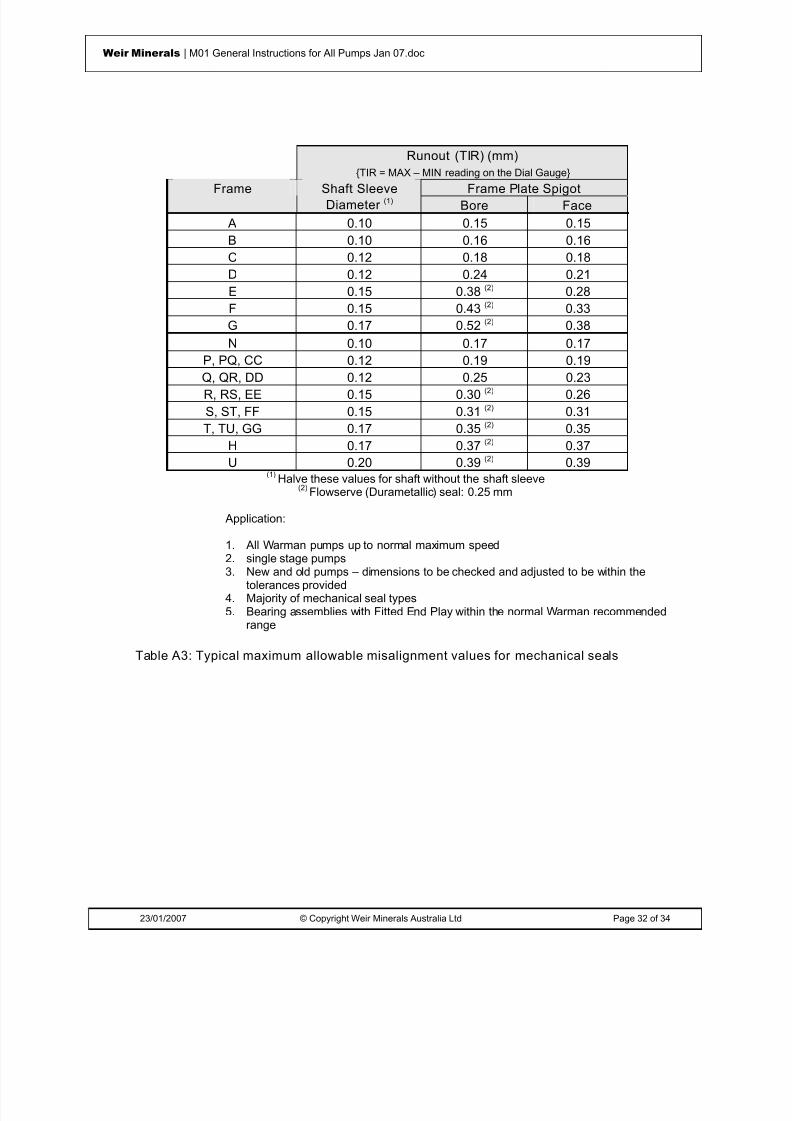
Runout (TIR) (mm){TIR = MAX – MIN reading on the Dial Gauge}
Frame Plate SpigotFrame Shaft SleeveDiameter (1) Bore Face
A 0.10 0.15 0.15B 0.10 0.16 0.16C 0.12 0.18 0.18D 0.12 0.24 0.21E 0.15 0.38 (2) 0.28F 0.15 0.43 (2) 0.33G 0.17 0.52 (2) 0.38N 0.10 0.17 0.17
P, PQ, CC 0.12 0.19 0.19Q, QR, DD 0.12 0.25 0.23R, RS, EE 0.15 0.30 (2) 0.26S, ST, FF 0.15 0.31 (2) 0.31T, TU, GG 0.17 0.35 (2) 0.35
H 0.17 0.37 (2) 0.37U 0.20 0.39 (2) 0.39
(1) Halve these values for shaft without the shaft sleeve(2) Flowserve (Durametallic) seal: 0.25 mm
Application:
1. All Warman pumps up to normal maximum speed
2. single stage pumps3. New and old pumps – dimensions to be checked and adjusted to be within thetolerances provided
4. Majority of mechanical seal types5. Bearing assemblies with Fitted End Play within the normal Warman recommended
range
Table A3: Typical maximum allowable misalignment values for mechanical seals

8/15/2019 r1_OF 71289_6 FF-AHF
http://slidepdf.com/reader/full/r1of-712896-ff-ahf 41/333
23/01/2007 © Copyright Weir Minerals Australia Ltd Page 33 of 34
Weir Minerals | M01 General Instructions for All Pumps Jan 07.doc
MECHANICAL SEALPROBLEM
CAUSE SOLUTION
• Infant orcatastrophic failure
• Seal faces cracked, chipped or
broken• Dry running – faces cracked or
scored• Misalignment of sealing faces• Pressure x velocity too high• Spring failure• Seal springs clogged and
inoperative• Seal faces over-compressed
• Review and revise installation
and/or operating conditions• Recondition seal by replacing
failed parts• Change seal specification or
materials• Add flush or throttling bush to
reduce contaminants reaching theseal
• Seal leakage • Seal faces cracked• Seal faces worn, scored or
misaligned• O-ring leaking• Secondary seal worn or
cracked
• Review and revise installationand/or operating conditions
•
Replace worn seal faces, O-ring orsecondary seals• Relap seal faces
• Contaminatedbarrier fluid
• Seal faces cracked or worn • Review and revise installationand/or operating conditions
• Reduce TDS of barrier fluid• Short seal Life • Operating pressure or
temperature above seal rating• Wear of seal body• Failure or seal face drive pins• Worn seal faces
• Reduce variations in operatingconditions
• Change to harder face material
Caution
1. Mechanical seals require a controlled and stable environment to ensure long and reliableoperation.
2. The seal manufacturers operating and maintenance instructions / procedures must be strictlyadhered too. Note that these instructions may include torque settings for the mechanical seallocking collar.
3. The mechanical seal warranty will most likely be voided if a failed seal has been subjected todry running, water hammer, low suction pressures or high suction lifts, cavitation, excessvibration, thermal shock, reverse rotation or dead-heading / low-flow conditions that are
linked to its failure.4. Prior to operating for the first time, the mechanical seal setting tabs must be removed and any flush or quench liquid connections checked that they will supply the required flowand pressure. Access to the mechanical seal is obtained by first removing the seal guard.
5. It is normally recommended that impellers without backvanes are used for mechanical sealsto reduce the flow and turbulence wear in the seal chamber.
Table A4: Typical mechanical seal problems and solutions

8/15/2019 r1_OF 71289_6 FF-AHF
http://slidepdf.com/reader/full/r1of-712896-ff-ahf 42/333
© Weir Minerals Australia Ltd 2007. Weir Minerals Australia Ltd is the owner of the Copyright in this document. The document and its text, images, diagrams, data andinformation it contains must not be copied or reproduced in whole or in part, in any form or by any means, without the prior written consent of Weir Minerals Australia Ltd.
Office of origin : Pump Technology Centre, Artarmon Reference : Pump Manuals
Date : 23 January 2007 Last Issued: July 2005
Assembly & MaintenanceInstructionsSupplement ‘P3’Series ‘A’ Slurry Pumps Types ‘AH’ & ‘M’

8/15/2019 r1_OF 71289_6 FF-AHF
http://slidepdf.com/reader/full/r1of-712896-ff-ahf 43/333
23/01/2007 © Copyright Weir Minerals Australia Ltd Page 2 of 48
Weir Minerals | P03 Series 'A' Slurry Pumps (AH & M) Jan 07.doc
WarningsPersonnel injury and / or equipment damage could result from not observing the followingIMPORTANT SAFETY INFORMATION
. • A pump is both a pressure vessel and a piece of rotating equipment . All standard safetyprecautions for such equipment should be followed before and during installation, operation andmaintenance.
• For auxiliary equipment (motors, belt drives, couplings, gear reducers, variable speed drives,mechanical seals, etc) all related safety precautions should be followed and appropriateinstruction manuals consulted before and during installation, operation, adjustment andmaintenance.
• All guards for rotating equipment must be correctly fitted before operating the pump includingguards temporarily removed for gland inspection and adjustment. Seal guards should not be
removed or opened while the pump is running. Personal injury may result from contact withrotating parts, seal leakage or spray.•
Driver rotation must be checked before belts or couplings are connected.•
Pumps must not be operated at low or zero flow conditions for prolonged periods, or underany circumstances that could cause the pumping liquid to vaporise. Personnel injury andequipment damage could result from the high temperature and pressure created.
• Pumps must be used only within their allowable limits of pressure, temperature and speed.These limits are dependent on the pump type, configuration and materials used.
• Do not apply heat to t he impeller boss or nose in an effort to loosen the impeller thread priorto impeller removal. Personnel injury and equipment damage could result from the impellershattering or exploding when the heat is applied.
• Do not feed very hot or very cold liquid into a pump which is at ambient temperature.Thermal shock may cause the pump casing to crack.
• LIFTING of components
• Tapped holes (for eye bolts) and lugs (for lifting shackles) on Warman pumps are forlifting Individual parts only .
• Lifting devices of adequate capacity must be used wherever they are required to beused.
• Safe workshop practices should be applied during all assembly and maintenance work.• Personnel must never work under suspended loads.
• The pump must be fully isolated before any maintenance work, inspection or troubleshootinginvolving work on sections which are potentially pressurised (eg casing, gland, connectedpipework) or involving work on the mechanical drive system (eg shaft, bearing assembly,coupling). Power to the electric motor must be isolated and tagged out. It must be proven thatthe intake and discharge openings are totally isolated from all potentially pressurisedconnections and that they are and can only be exposed to atmospheric pressure.
•
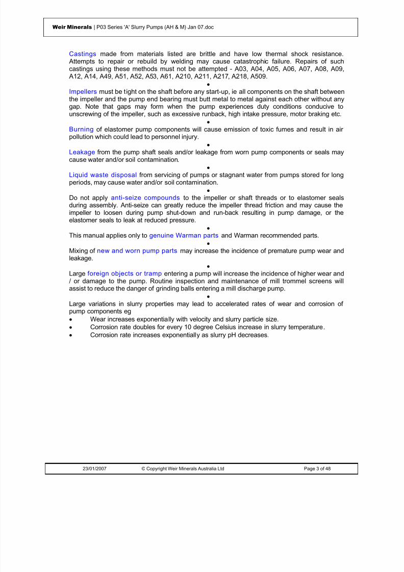
8/15/2019 r1_OF 71289_6 FF-AHF
http://slidepdf.com/reader/full/r1of-712896-ff-ahf 44/333
23/01/2007 © Copyright Weir Minerals Australia Ltd Page 3 of 48
Weir Minerals | P03 Series 'A' Slurry Pumps (AH & M) Jan 07.doc
Castings made from materials listed are brittle and have low thermal shock resistance. Attempts to repair or rebuild by welding may cause catastrophic failure. Repairs of suchcastings using these methods must not be attempted - A03, A04, A05, A06, A07, A08, A09,
A12, A14, A49, A51, A52, A53, A61, A210, A211, A217, A218, A509.•
Impellers must be tight on the shaft before any start-up, ie all components on the shaft betweenthe impeller and the pump end bearing must butt metal to metal against each other without anygap. Note that gaps may form when the pump experiences duty conditions conducive tounscrewing of the impeller, such as excessive runback, high intake pressure, motor braking etc.
• Burning of elastomer pump components will cause emission of toxic fumes and result in airpollution which could lead to personnel injury.
• Leakage from the pump shaft seals and/or leakage from worn pump components or seals maycause water and/or soil contamination.
• Liquid waste disposal from servicing of pumps or stagnant water from pumps stored for longperiods, may cause water and/or soil contamination.
• Do not apply anti-seize compounds to the impeller or shaft threads or to elastomer sealsduring assembly. Anti-seize can greatly reduce the impeller thread friction and may cause theimpeller to loosen during pump shut-down and run-back resulting in pump damage, or theelastomer seals to leak at reduced pressure.
• This manual applies only to genuine Warman parts and Warman recommended parts.
• Mixing of new and worn pump parts may increase the incidence of premature pump wear andleakage.
• Large foreign objects or tramp entering a pump will increase the incidence of higher wear and/ or damage to the pump. Routine inspection and maintenance of mill trommel screens willassist to reduce the danger of grinding balls entering a mill discharge pump.
• Large variations in slurry properties may lead to accelerated rates of wear and corrosion ofpump components eg• Wear increases exponentially with velocity and slurry particle size.• Corrosion rate doubles for every 10 degree Celsius increase in slurry temperature.• Corrosion rate increases exponentially as slurry pH decreases.

8/15/2019 r1_OF 71289_6 FF-AHF
http://slidepdf.com/reader/full/r1of-712896-ff-ahf 45/333
23/01/2007 © Copyright Weir Minerals Australia Ltd Page 4 of 48
Weir Minerals | P03 Series 'A' Slurry Pumps (AH & M) Jan 07.doc
ISSUED: JA NUARY 2007 LA ST ISSUE: JULY 2005
WARMAN PUMPS ASSEMBLY AND MAINTENANCE INSTRUCTIONS
SUPPLEMENT ‘P3’
SLURRY PUMPSTYPE 'AH' & ‘M’
CONTENTS
WARNINGS 2
CONTENTS 4
1 INTRODUCTION 6 Advant ages and Uses of Series ‘A’ Type 'AH' & 'M' Slurry Pumps 6 Bearing Assembly – Maintenance & Assembly Instru ctio ns 6 Centrifugal Sealing - Lubr ication 6 Parts Identification 7
2 ASSEMBLY INSTRUCTIONS 7 Frame Assembly 8
Fitting Bearing Assembly to Base - See Figures 1 & 6 8 Pump Assembly 9
Fitting Frame Plate and Cover Plate Bolts - See Figure 2 9 Seal Assembly 11
Gland Assembly 11 Centrifugal Seal Assembly 17 Warman Mechanical Seal Assembly 24
Pump Assembly 24Metal Liners - Two Piece 26 Metal Liners - Three Piece 29 Elastomer Liners - Two Piece 32 Elastomer Liners - Three Piece 34 Elastomer Liners - Four Piece 37
Assembled Pump: Fitting Joint Rings - See Figure 12 40 Impeller Adjustment - See Figures 13 & 6 41
3 PUMP DISMANTLING & IMPELLER REMOVAL 42
4 PRODUCT MODIFICATION ADVICE (PMA) 43
BASIC PART NUMBERS & PARTS LIST 46

8/15/2019 r1_OF 71289_6 FF-AHF
http://slidepdf.com/reader/full/r1of-712896-ff-ahf 46/333
23/01/2007 © Copyright Weir Minerals Australia Ltd Page 5 of 48
Weir Minerals | P03 Series 'A' Slurry Pumps (AH & M) Jan 07.doc
APPENDIX 48

8/15/2019 r1_OF 71289_6 FF-AHF
http://slidepdf.com/reader/full/r1of-712896-ff-ahf 47/333
23/01/2007 © Copyright Weir Minerals Australia Ltd Page 6 of 48
Weir Minerals | P03 Series 'A' Slurry Pumps (AH & M) Jan 07.doc
1 INTRODUCTIONSupplement 'P3' should be read in conjunction with the following Warman Assembly andMaintenance Instruction Supplements:
M1 - General Instructions applicable to ALL TYPES of Warman Pumps
M2 - Impeller Release Collar
M4 - Warman Mechanical Seals
BA1, BA2, BA3 or BA4 - One of these depending on whether Heavy Duty, Basic,Modified Basic or Oil Filled Bearing Assemblies are used respectively.
Advantages and Uses of Ser ies ‘A’ Type 'AH' & 'M' Slurry Pumps
Designed for the continuous pumping of highly abrasive and/or corrosive slurries. Thesepumps feature a wide choice of replaceable hard metal or pressure moulded elastomerliners and impellers and are all interchangeable within the same casing.
The Warman centrifugal shaft seal is commonly used, but an interchangeable packedgland seal is also available for every pump. Special mechanical seals for slurry serviceare being developed.
Ease of maintenance features include:• Through bolt design• Minimum number of casing bolts• Slip fit replaceable Shaft sleeve• Cartridge type Bearing Assembly• Cast in Impeller thread• Replaceable liners are positively attached• Impeller Release Collar on large models
Bearing Assembly – Maintenance & Assembly Instruct ions
The bearing assembly is assembled and maintained according to the instructionscontained in the respective Warman Supplement 'BA1' to 'BA4' according to the TYPE ofbearing assembly utilised.
Centrifugal Sealing - Lubrication
In centrifugally sealed pumps, lubricate the static seal chamber sparingly but regularly,by means of the grease cup.
The grease for the centrifugally sealed pump static seal chamber should have thefollowing specifications:
A lithium complex soap thickener grease with EP additives and oxidation inhibitors.
N.L.G.I. Consistency No 2
Drop Point 260 °C

8/15/2019 r1_OF 71289_6 FF-AHF
http://slidepdf.com/reader/full/r1of-712896-ff-ahf 48/333
23/01/2007 © Copyright Weir Minerals Australia Ltd Page 7 of 48
Weir Minerals | P03 Series 'A' Slurry Pumps (AH & M) Jan 07.doc
Work penetration 25°C A.S.T.M. 265 - 295
RECOMMENDED GREASE: MOBIL HP or equivalent.
Parts Identification
The comments in Warman Bearing Assembly Supplements regarding Warman BasicNumbers incorporated in Warman Part Numbers applies in the same manner to WarmanPump component parts.
For full description and part number identification, refer to the appropriate WARMANComponents Diagram. Names and Basic Numbers are used in assembly instructions inthis manual. The relevant Warman Basic Numbers are listed at the end of thissupplement.
In all correspondence with Weir Warman Ltd, or their representatives, and especiallywhen ordering spare parts, it is advisable to use correct names as well as full partnumbers to prevent misunderstandings or wrong deliveries. When in doubt, the pump
serial number should be quoted as well.2 ASSEMBLY INSTRUCTIONS
A Components Diagram of the particular pump being assembled will assist in followingthe pump assembly instruction steps as detailed in the following sections.
When pumps have been dismantled for complete overhaul, all parts should be closelyinspected and new parts checked for correct identification.
Used parts being replaced should be thoroughly cleaned and repainted where required.Mating faces and spigots should be free of rust, dirt and burrs and given a coat of greasebefore they are fitted together to assist future overhaul.
It is preferable to renew small bolts and set screws during overhaul and all threadsshould be coated with graphite grease before assembly. It is also recommended that allrubber seals should be replaced during major overhauls as rubber tends to harden andseals lose their effectiveness.

8/15/2019 r1_OF 71289_6 FF-AHF
http://slidepdf.com/reader/full/r1of-712896-ff-ahf 49/333
23/01/2007 © Copyright Weir Minerals Australia Ltd Page 8 of 48
Weir Minerals | P03 Series 'A' Slurry Pumps (AH & M) Jan 07.doc
Frame Assembly
Figure 1
Fitting Bearing Assembly t o Base - See Figures 1 & 6
1. Insert ADJUSTING SCREW (001) in BASE (003) from outside. Screw on one nut
and fully tighten. Screw on two additional nuts with two flat washers in between.These nuts to be left loose and maximum distance apart.
2. Apply grease to machined surfaces (bearing housing support cradle) in base.
3. Lower BEARING ASSEMBLY (005) into base. Approximately match machinedsurfaces of the housing with surfaces in the base. Check that the bearing housinglug has fitted over the adjusting screw in the base and is also between the nutsand washers. Fit CLAMP BOLTS (012) through base from underneath. DropCLAMP WASHER (011) over each bolt (domed side up) and screw on nuts. Fullytighten clamp bolts on side 'A', ie. on left hand side of base when looking fromimpeller end refer to Figures 1 and 6. The bolts on the opposite side 'B' should notbe tightened for the time being. Leave snug only, to maintain alignment but allow
axial movement.4. Grease SHAFT (073) protruding from LABYRINTH (062) at impeller end. This
application of grease will assist fitting and removal of shaft components andprevent damage by moisture to the shaft.
5. Fit two pieces of timber to underside of base or appropriate assembly cradle toprevent the pump from tipping forward during assembly of the wet end.

8/15/2019 r1_OF 71289_6 FF-AHF
http://slidepdf.com/reader/full/r1of-712896-ff-ahf 50/333
23/01/2007 © Copyright Weir Minerals Australia Ltd Page 9 of 48
Weir Minerals | P03 Series 'A' Slurry Pumps (AH & M) Jan 07.doc
Check that the base is at a sufficient height from the floor to allow assembly of thewet end components.
Pump Assembly
Figure 2
Fitti ng Frame Plate and Cover Plate Bolts - See Figure 2
1. Fit FRAME PLATE (032) to base, making certain that the frame plate spigot hasengaged with the corresponding base recess. Grease the recess to assist infuture removal.
With large pumps, frame plates are provided with radially tapped holes for EYEBOLTS (-) to facilitate lifting.
2. Insert FRAME PLATE STUDS (039) or FRAME PLATE BOLTS (034), dependingon the pump. Fit nuts and fully tighten.
In some pumps the frame plate is bolted externally (studs are used). In otherpumps, bolts are used and are inserted from the frame plate.
The frame plate can be rotated to provide eight alternate discharge positions withthe exception of B frame pumps and the 3/2 AH pump, where only 4 positions areavailable.
Rubber Lined Pumps:
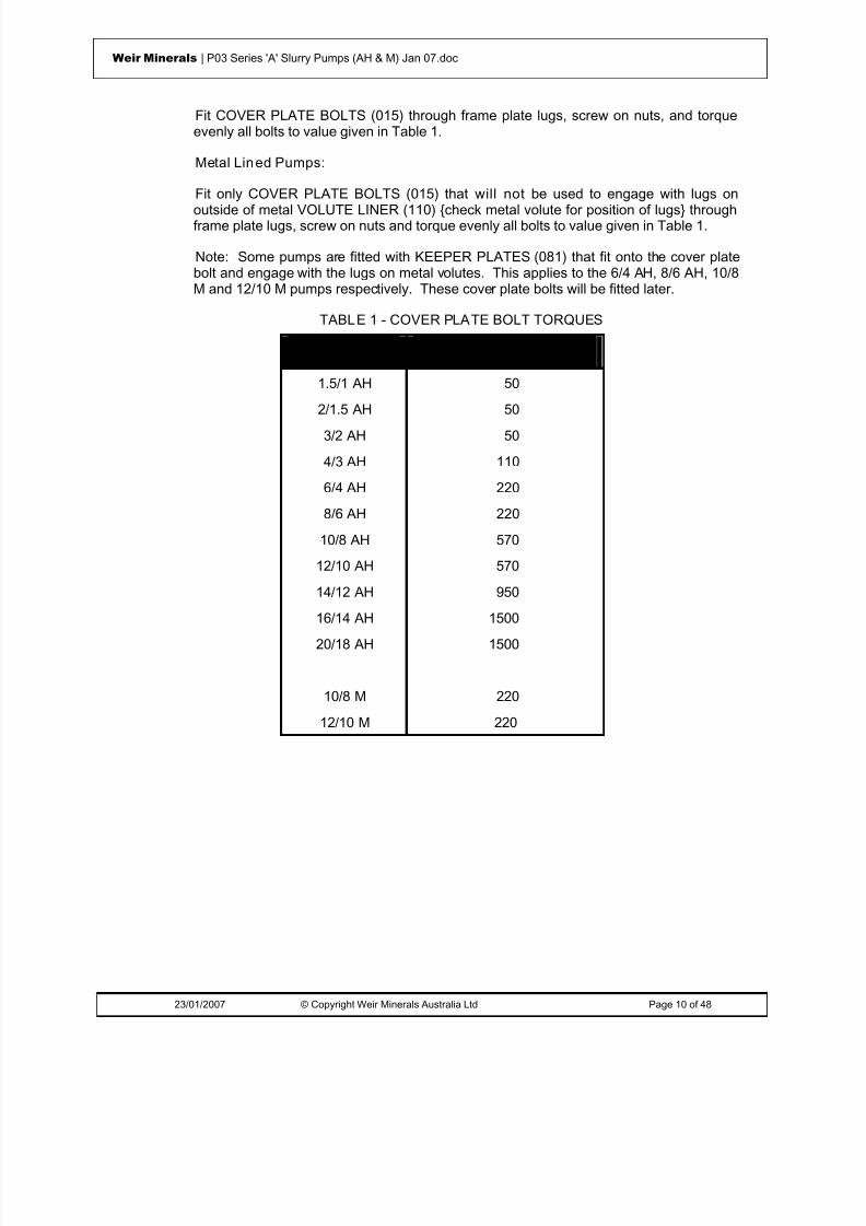
8/15/2019 r1_OF 71289_6 FF-AHF
http://slidepdf.com/reader/full/r1of-712896-ff-ahf 51/333
23/01/2007 © Copyright Weir Minerals Australia Ltd Page 10 of 48
Weir Minerals | P03 Series 'A' Slurry Pumps (AH & M) Jan 07.doc
Fit COVER PLATE BOLTS (015) through frame plate lugs, screw on nuts, and torqueevenly all bolts to value given in Table 1.
Metal Lined Pumps:
Fit only COVER PLATE BOLTS (015) that will not be used to engage with lugs onoutside of metal VOLUTE LINER (110) {check metal volute for position of lugs} throughframe plate lugs, screw on nuts and torque evenly all bolts to value given in Table 1.
Note: Some pumps are fitted with KEEPER PLATES (081) that fit onto the cover platebolt and engage with the lugs on metal volutes. This applies to the 6/4 AH, 8/6 AH, 10/8M and 12/10 M pumps respectively. These cover plate bolts will be fitted later.
TABLE 1 - COVER PLATE BOLT TORQUES
PUMP MAXIMUM TORQUE (Nm)
1.5/1 AH 50
2/1.5 AH 503/2 AH 50
4/3 AH 110
6/4 AH 220
8/6 AH 220
10/8 AH 570
12/10 AH 570
14/12 AH 950
16/14 AH 1500
20/18 AH 1500
10/8 M 220
12/10 M 220

8/15/2019 r1_OF 71289_6 FF-AHF
http://slidepdf.com/reader/full/r1of-712896-ff-ahf 52/333
23/01/2007 © Copyright Weir Minerals Australia Ltd Page 11 of 48
Weir Minerals | P03 Series 'A' Slurry Pumps (AH & M) Jan 07.doc
Seal Assembly
Figure 3
Gland AssemblyFitting Stuffing Box, Lantern Restrictor, (or Neck and Lantern Rings), Packing, Gland,Shaft Sleeve, Shaft Spacer and Shaft Sleeve O-Rings - See Figure 3 and 7
Gland arrangements for stuffing boxes are shown on Warman drawing A4-110-0-115795attached. Select the arrangement that best suits the pump application. Non-metallicLANTERN RESTRICTORS (118-1) offer the advantage of minimising the gland sealingwater requirements.
Two methods are described below for assembling the gland depending on the size of theframe. Either method can be used if it is found to be more suitable.
Figure 3 illustrates the relative position of impeller release collars, sleeves, shaftsleeves, O-Rings etc on the shaft. The particular arrangement of these components canvary from one pump to another. Table 2 lists components which are assembled onto theshaft in the order in which they are fitted, commencing at the LABYRINTH (062) at thepump end of the bearing assembly. Pumps with similar arrangements are groupedtogether. Generally the modified basic frames (CC, DD etc) will have the same shaftcomponents as the basic frames (B, C, D, etc).

8/15/2019 r1_OF 71289_6 FF-AHF
http://slidepdf.com/reader/full/r1of-712896-ff-ahf 53/333
23/01/2007 © Copyright Weir Minerals Australia Ltd Page 12 of 48
Weir Minerals | P03 Series 'A' Slurry Pumps (AH & M) Jan 07.doc
TABLE 2 - GLAND SEAL
FRAME PUMP SHAFT COMPONENTS (inorder from Labyrinth to
Impeller)
G 16/14 G-AH 109 Shaft O-Ring076 Shaft Sleeve (long)109 Shaft O-Ring
NP 3/2 NP-AH, 8/6 R-AH 109 Shaft O-RingR 10/8 R-M & 12/10 R-M 076 Shaft Sleeve (long)
RS 12/10 RS-M 064 Impeller O-Ring
B 1.5/1 B-AH & 1.5/1 N-AH 109 Shaft O-RingC 2/1.5 B-AH & 2/1.5 N-AH 075 Shaft SleeveN 3/2 C-AH & 3/2 P-AH 109 Shaft O-RingP 117 Shaft Spacer
217 Impeller O-Ring
C 4/3 C-AH & 4/3 P-AH 109 Shaft O-RingD 4/3 D-AH & 4/3 Q-AH 075 Shaft SleeveE 10/8 E-M & 12/10 E-M 109 Shaft O-RingP 6/4 E-AH 117 Shaft SpacerQ 8/6 E-AH 064 Impeller O-Ring
D 6/4 D-AH & 6/4 Q-AH 109 Shaft O-RingF 8/6 F-AH 075 Shaft SleeveG 10/8 F-M & 12/10 F-M 109 Shaft O-RingQ 10/8 G-AH & 12/10 G-AH 117 Shaft Spacer
14/12 G-AH 109 Shaft O-Ring
G 20/18 G-AH & 20/18 TU-AH 109 Shaft O-RingTU 239 Impeller Release Collar
109 Shaft O-Ring076 Shaft Sleeve (long)
109 Shaft O-Ring
TU 16/14 TU-AH 109 Shaft O-Ring239 Impeller Release Collar
109 Shaft O-Ring076 Shaft Sleeve (long)

8/15/2019 r1_OF 71289_6 FF-AHF
http://slidepdf.com/reader/full/r1of-712896-ff-ahf 54/333

8/15/2019 r1_OF 71289_6 FF-AHF
http://slidepdf.com/reader/full/r1of-712896-ff-ahf 55/333
23/01/2007 © Copyright Weir Minerals Australia Ltd Page 14 of 48
Weir Minerals | P03 Series 'A' Slurry Pumps (AH & M) Jan 07.doc
2. Place a LANTERN RESTRICTOR (118) (small diameter down) in gland recess torest on retaining lip. In some applications, a NECK RING (067) is used in place ofthe lantern restrictor.
3. Stand SHAFT SLEEVE (075 or 076) on end and slide through lantern restrictor.
4. Fit following items in turn:
(a) First PACKING RING (111) of correct length to fill annulus;
(b) Remaining packing rings (stagger packing joints) to almost completely fill theannulus. Flatten each one separately.
Note: When a neck ring is used, place LANTERN RING (063) on top of firstring of packing and press down to flatten first ring; then fit remaining packingrings (stagger packing joints).
5. Assemble GLAND (044) halves, insert GLAND CLAMP BOLTS (126) and fullytighten. Place gland in stuffing box and push down to compress packing rings.Insert GLAND BOLTS (045) and just nip up nuts sufficiently to hold shaft sleeve(final adjustment will be made when testing pump).
6. From the pump components diagram or from Table 2 (for the particular pumpbeing assembled) ascertain the components which fit between the LABYRINTH(062) and SHAFT SLEEVE (075 or 076). Fit these components to the shaft.Instructions for fitting an IMPELLER RELEASE COLLAR (239) are contained inWarman Supplement 'M2'.
7. Insert assembled stuffing box in frame plate and tap into position with a mallet.Locate stuffing box with water connection at top. For the bigger frames, assemblyof the stuffing box into the frame plate is best carried out using LIFTING PLATE(310) refer to Figure 7.
The shaft sleeve will probably remain forward. It should be pushed back to themating part on the shaft. Check that any O-rings are correctly positioned in grooves.
8. Fit remaining O-rings and shaft spacers as per Table 2.
Note:
(c) To assist in holding the last O-ring in position which seals against the Impeller,apply heavy grease to the O-ring groove.
(d) All the O-rings in their respective grooves will be compressed and fullycovered by these metallic parts when the impeller is screwed onto the shaft.
9. Liberally grease shaft thread.

8/15/2019 r1_OF 71289_6 FF-AHF
http://slidepdf.com/reader/full/r1of-712896-ff-ahf 56/333
23/01/2007 © Copyright Weir Minerals Australia Ltd Page 15 of 48
Weir Minerals | P03 Series 'A' Slurry Pumps (AH & M) Jan 07.doc
FRAMES: G, GG, H, ST, T, TU & U
1. From a components diagram or from Table 2 (for the particular pump beingassembled) ascertain the components which fit between the LABYRINTH (062)and IMPELLER (-). Fit these components to the shaft. Instructions for fittingIMPELLER RELEASE COLLAR (239) are contained in Warman Supplement 'M2'
Note:
(a) To assist in holding the last O-ring in position which seals against the impeller,apply heavy grease to the O-ring groove.
(b) All the O-rings in their respective grooves will be compressed and fully coveredby these metallic parts when the impeller is screwed onto the shaft.
2. Fit LANTERN RESTRICTOR (118) (small diameter out) freely over shaft and pushagainst bearing housing. In some cases a LANTERN RING (063) followed byNECK RING (067) is used in place of the lantern restrictor.
3. Attach STUFFING BOX LIFTING PLATE (310) to STUFFING BOX (078) onopposite side of lugs using three jacking screws provided and ensure that waterconnection in the stuffing box is in line with the lifting beam see Figure 7.
4. Lift stuffing box with lifting plate by means of a hoist and insert stuffing box inframe plate, tap in position with mallet.
5. Fit CLAMP BRACKET (022) using CLAMP BRACKET SET SCREW to temporarysecure the stuffing box into the frame plate during subsequent assemblyprocedures.
6. Assembly of all gland parts in stuffing box should be carried out in the followingmanner after all other parts of the pump have been assembled.
(a) Slide LANTERN RESTRICTOR (118) or NECK RING (067) inside stuffing boxagainst retaining lip.
(b) Fit first PACKING RING (111) of correct length to fill annulus and push againstneck ring.
(c) Slide LANTERN RING (063) and press to flatten first ring. When a lanternrestrictor is used, the lantern ring is omitted.
(d) Fit packing rings to almost completely fill the annulus (stagger packing jointsand flatten each ring).
(e) Assemble GLAND (044) halves over shaft sleeve with gland spigot towardsstuffing box, insert GLAND CLAMP BOLTS (126) and fully tighten. Push into
stuffing box to compress packing rings. Insert GLAND BOLTS (045) and nipup. Final adjustment will be made when testing the pump.
7. Alternatively it is possible to fit the shaft sleeve and the gland parts into the stuffingbox and then fit this sub-assembly into the frame plate. Caution has to be givennot to allow the shaft sleeve to fall out during fitup.
8.
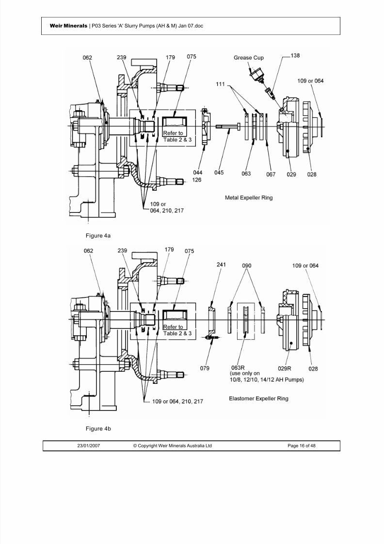
8/15/2019 r1_OF 71289_6 FF-AHF
http://slidepdf.com/reader/full/r1of-712896-ff-ahf 57/333
23/01/2007 © Copyright Weir Minerals Australia Ltd Page 16 of 48
Weir Minerals | P03 Series 'A' Slurry Pumps (AH & M) Jan 07.doc
Figure 4a
Figure 4b
8/15/2019 r1_OF 71289_6 FF-AHF
http://slidepdf.com/reader/full/r1of-712896-ff-ahf 58/333
23/01/2007 © Copyright Weir Minerals Australia Ltd Page 17 of 48
Weir Minerals | P03 Series 'A' Slurry Pumps (AH & M) Jan 07.doc
Centrifugal Seal A ssembly
[METAL (029) OR ELASTOMER (029R) EXPELLER RING]
Fitting Expeller Ring, Neck and Lantern Rings, Packing, Shaft Sleeve, Shaft Sleeve O-Rings and Expeller - See Figures 4a, 4b and 7
For high seal (HS) expeller assemblies refer to Warman Manual Supplement M8.
Two types of expeller ring are available - metal or elastomer.
Metal expeller rings are generally fitted with packing.
Elastomer expeller rings are recommended to be fitted with LIP SEALS ONLY asthere is no provision for lubrication, and the elastomer cannot conduct heat away thatwould be generated by packing.
Different methods are described below for assembling the centrifugal seal, depending onthe size of the pump or pump frame. Either method can be used if it is found to be moresuitable.
Figures 4a and 4b illustrate the relative position of impeller release collar, sleeves, shaftsleeves, O-rings etc on the shaft. The particular arrangement of these components varyfrom one pump to another. Table 2 lists components for a gland sealed pump which areassembled onto the shaft in the order in which they are fitted commencing at theLABYRINTH (062) at the pump end of the bearing assembly. Pumps with similararrangements are grouped together. Generally the modified basic frames (CC, DD etc)will have the same shaft components as the basic frames (B, C, D, etc).
In most cases, the EXPELLER (028) substitutes directly for the SHAFT SPACER (117)in the gland sealed arrangement. All other sleeves/O-Rings etc remain the same.
Some exceptions to the above are listed in Table 3 .

8/15/2019 r1_OF 71289_6 FF-AHF
http://slidepdf.com/reader/full/r1of-712896-ff-ahf 59/333
23/01/2007 © Copyright Weir Minerals Australia Ltd Page 18 of 48
Weir Minerals | P03 Series 'A' Slurry Pumps (AH & M) Jan 07.doc
TABLE 3 - CENTRIFUGAL SEAL
FRAME
PUMP SHAFT COMPONENTS(in order from Labyrin th to Impeller)
D 6/4 D-AH 109 Shaft O-RingF 8/6 F-AH 075 Shaft SleeveQ 6/4 Q-AH 109 Shaft O-Ring
028 Expeller064 Impeller O-Ring or 109 Shaft O-Ring
C 4/3 C-AH 109 Shaft O-Ring075 Shaft Sleeve109 Shaft O-Ring
CAM117E Shaft Spacer
109 Shaft Spacer O-RingD028 Expeller
064 Impeller O-Ring
E 8/6 E-AH & 8/6 R-AH 109 Shaft O-RingR 10/8 E-M & 10/8 R-M 075 Shaft Sleeve
RS 12/10 E-M & 12/10 R-M 109 Shaft O-Ring12/10 RS-M EAM117E Shaft Spacer
F109 Shaft Spacer O-RingF028 Expeller
109 Shaft O-Ring
G 16/14 G-AH 109 Shaft O-RingTU 20/18 G-AH & 20/18 TU-AH 239 Impeller Release Collar
109 Shaft O-Ring075 Shaft Sleeve109 Shaft O-Ring
028 Expeller109 Shaft O-Ring
TU 16/14 TU-AH 109 Shaft O-Ring239 Impeller Release Collar
109 Shaft O-Ring075 Shaft Sleeve109 Shaft O-Ring
028 Expeller064 Impeller O-Ring

8/15/2019 r1_OF 71289_6 FF-AHF
http://slidepdf.com/reader/full/r1of-712896-ff-ahf 60/333
23/01/2007 © Copyright Weir Minerals Australia Ltd Page 19 of 48
Weir Minerals | P03 Series 'A' Slurry Pumps (AH & M) Jan 07.doc
FRAME
PUMP SHAFT COMPONENTS(in order from Labyrin th to Impeller)
T 10/8 T-AH 109 Shaft O-Ring12/10 T-AH 239 Impeller Release Collar
109 Shaft O-Ring179 Shaft Sleeve Spacer
109 Shaft O-Ring075 Shaft Sleeve109 Shaft O-Ring
028 Expeller109 Shaft O-Ring
ST 10/8 ST-AH 210 Shaft O-Ring12/10 ST-AH 239 Impeller Release Collar14/12 ST-AH 210 Shaft O-Ring
075 Shaft Sleeve210 Shaft O-Ring
028 Expeller210 Shaft O-Ring
Metal Expeller Ring (029) - Figure 4a
To fit PACKING (111) to metal expeller rings, follow the instructions below depending onthe size of the pump frame:
FRAMES: B, C, D, E, F, CC, DD, EE, FF, NP, P, PQ, Q, QR, R, RS & S
1. Place EXPELLER RING (029) flat on bench (gland side up).
2. Drop NECK RING (067) into gland recess as retaining lip.
3. Stand SHAFT SLEEVE (075) on end through neck ring.
4. Fit the following items in turn:
(a) First PACKING RING (111) of correct length to fill annulus.
(b) LANTERN RING (063) pressed down to flatten first ring.
(c) Remaining packing rings (stagger packing joints and flatten each ring) toalmost completely fill the annulus.
5. Assemble GLAND (044) halves, insert GLAND CLAMP BOLTS (126) and fullytighten. Place gland in expeller ring and push down to compress packing rings.Insert GLAND BOLTS (045) and just nip up nuts sufficiently to hold shaft sleeve(final adjustment will be made when testing the pump).
8/15/2019 r1_OF 71289_6 FF-AHF
http://slidepdf.com/reader/full/r1of-712896-ff-ahf 61/333
23/01/2007 © Copyright Weir Minerals Australia Ltd Page 20 of 48
Weir Minerals | P03 Series 'A' Slurry Pumps (AH & M) Jan 07.doc
6. From a components diagram or from Tables 2 and 3 (for the particular pump beingassembled) ascertain the components which fit between the LABYRINTH (062) andSHAFT SLEEVE (075). Fit these components to the shaft. Instructions for fitting anIMPELLER RELEASE COLLAR (239) are contained in Warman Supplement 'M2'.
7. Insert assembled expeller ring in frame plate and tap in position with mallet. Locateexpeller ring with grease inlet at top. Assembly of the expeller ring into the frameplate is best carried out using LIFTING PLATE (310) - refer to Figure 7.
8. The shaft sleeve will probably remain forward. It should be pushed back to themating part on the shaft. Check that any O-rings are correctly positioned in grooves.
9. Assemble remaining O-rings and shaft spacers as per Tables 2 and 3 onto shaftwhich fit between SHAFT SLEEVE (075) and EXPELLER (028).
10. Place EXPELLER (028) on shaft and press up to mating part on shaft.
11. Fit remaining O-RING (109 or 064) to groove on expeller.
Note:
(a) To assist in holding the last O-ring in position which seals against the Impeller,apply heavy grease to the O-ring groove.
(b) All the O-rings in their respective grooves will be compressed and fullycovered by these metallic parts when the impeller is screwed onto the shaft.
12. Liberally grease shaft thread.
13. Assembly of gland lubricating parts will be done after all other parts of the pumphave been assembled.
14. Fit GREASE CUP ADAPTOR (138) and GREASE CUP (-) to expeller ring. Fill cupwith recommended grease and screw down cup to charge lantern ring. Top up cup.
FRAMES: G, GG, H, ST, T, TU, & U
1. From a components diagram or from Tables 2 and 3 (for the particular pump beingassembled) ascertain the components which fit between the LABYRINTH (062) andEXPELLER (028). Fit these components to the shaft. Instructions for fitting anIMPELLER RELEASE COLLAR (239) are contained in Warman Supplement 'M2'.
2. Fit LANTERN RING (063) followed by NECK RING (067) freely over sleeves andpush both against bearing housing.
3. Attach EXPELLER RING LIFTING BEAM (310) to EXPELLER RING (029) onopposite side of lugs using three jacking screws provided and ensure that thegrease inlet in the expeller ring is in line with the lifting beam refer to Figure 7.
4. Lift expeller ring with lifting beam by means of a hoist and insert expeller ring inframe plate, tap in position with mallet. Grease location recess to assist laterremoval.
5. Assembly of all gland parts in expeller ring will be carried out in the following mannerafter all other parts of the pump have been assembled.

8/15/2019 r1_OF 71289_6 FF-AHF
http://slidepdf.com/reader/full/r1of-712896-ff-ahf 62/333

8/15/2019 r1_OF 71289_6 FF-AHF
http://slidepdf.com/reader/full/r1of-712896-ff-ahf 63/333
23/01/2007 © Copyright Weir Minerals Australia Ltd Page 22 of 48
Weir Minerals | P03 Series 'A' Slurry Pumps (AH & M) Jan 07.doc
2. Fit two EXPELLER RING STUDS (079) in expeller ring tapped holes provided andfully tighten.
3. Insert two LIP SEALS (090) {lip down} in gland recess against retaining lip. Lips topoint INTO pump so they are activated by internal pressure. To ease fitting smearoutside diameter of seals with liquid soap or rubber lubricant. Note that LANTERNRING (063R) is used ONLY on 10/8, 12/10 and 14/12 AH pumps.
4. Place LIP SEAL GLAND (241) in expeller ring, fit nuts to studs and fully tighten.(Gland adjustment is not required).
ALL PUMP SIZES:
1. From a components diagram or from Tables 2 and 3 (for the particular pump beingassembled) ascertain the components which fit between the LABYRINTH (062) andSHAFT SLEEVE (075). Fit these components to the shaft. Instructions for fitting anIMPELLER RELEASE COLLAR (239) are contained in Warman Supplement 'M2'.
2. Insert assembled expeller ring over shaft sleeve into frame plate and tap in position
with mallet. Locate expeller ring with studs on horizontal plane. The shaft sleevewill probably remain forward. It should be pushed back to the mating part on theshaft. Check that any O-rings are correctly positioned in grooves.
3. Assemble remaining O-rings and shaft spacers as per Tables 2 and 3 onto shaftwhich fit between SHAFT SLEEVE (075) and EXPELLER (028).
4. Place EXPELLER (028) on shaft and press up to mating part on shaft.
5. Fit remaining O-RING (109 or 064) to groove on expeller.
Note:
(a) To assist in holding the last O-ring in position which seals against the impeller,
apply heavy grease to the O-ring groove.(b) All the O-rings in their respective grooves will be compressed and fully
covered by these metallic parts when the impeller is screwed onto the shaft.
6. Liberally grease shaft thread.
Warman Mechanical Seal Assembly
For pumps fitted with a Warman Mechanical Seal (Warman Basic Number '162-50')follow the assembly and maintenance instructions contained in Warman Supplement'M4' .
The Warman Mechanical Seal is supplied as a cartridge seal ready to install in thepump. If the mechanical seal is in pieces, first assemble the components into a cartridgefollowing the instructions in Warman Supplement 'M4'.
Note: When fitting Warman Mechanical Seals the BEARING ASSEMBLY (005) needs tobe altered. Replace END COVER (024) at pump end of Bearing Assembly with ENDCOVER (024-50) by following instruction contained in Warman Supplement 'M4'.

8/15/2019 r1_OF 71289_6 FF-AHF
http://slidepdf.com/reader/full/r1of-712896-ff-ahf 64/333
23/01/2007 © Copyright Weir Minerals Australia Ltd Page 23 of 48
Weir Minerals | P03 Series 'A' Slurry Pumps (AH & M) Jan 07.doc
Pump Assembly
Depending on the TYPE OF LINERS being fitted - METAL or ELASTOMER, checkTable 4 for the relevant section for instructions on completing pump assembly (Note:liner fit-up is same regardless of frame used).
Metal and elastomer liners can be used interchangeably (depending on the finalapplication). A mix of metal and elastomer liners is also possible. In these cases followthe relevant instructions in the various sections as per Table 4 depending on thecombination used.
TABLE 4 - PUMP FIT-UP: CASING LINERS
METAL LINERS ELASTOMER LINERS
PUMP TWOPIECE
THREEPIECE
TWOPIECE
THREEPIECE
FOURPIECE
1.5/1 AH • -- • -- --
2/1.5 AH•
--•
-- --3/2 AH • -- • -- --
4/3 AH • -- • -- --
6/4 AH -- • -- • --
8/6 AH -- • -- • --
10/8 AH -- • -- • --
12/10 AH -- • -- • --
14/12 AH -- • -- -- •
16/14 AH -- • -- -- •
20/18 AH -- • -- -- •
10/8 M -- • -- • --
12/10 M -- • -- -- • • = Denotes Standard Liner Fit-up (Same regardless of FRAME used)

8/15/2019 r1_OF 71289_6 FF-AHF
http://slidepdf.com/reader/full/r1of-712896-ff-ahf 65/333
23/01/2007 © Copyright Weir Minerals Australia Ltd Page 24 of 48
Weir Minerals | P03 Series 'A' Slurry Pumps (AH & M) Jan 07.doc
Figure 5 Two Piece Metal Liners
Figure 6

8/15/2019 r1_OF 71289_6 FF-AHF
http://slidepdf.com/reader/full/r1of-712896-ff-ahf 66/333
23/01/2007 © Copyright Weir Minerals Australia Ltd Page 25 of 48
Weir Minerals | P03 Series 'A' Slurry Pumps (AH & M) Jan 07.doc
Figure 7
Metal Liners - Two Piece
Fitting Seal Ring, Frame Plate Liner Insert, Volute Liner Seals, Volute Liner, Impeller andCover Plate - See Figures 5, 6 and 7
For two piece metal lined pumps, the volute liner and 'front liner' (throatbush) are onepiece. This applies for pump sizes 1.5/1 AH, 2/1.5 AH, 3/2 AH and 4/3 AH.
1. Fit 'C'-section SEAL RING (122) onto rim of stuffing box or expeller ring. To aid inholding the seal in position during subsequent assembly steps, it is recommendedthat the seal be cemented to the stuffing box/expeller ring using rubber cement, andpreferably of the dry contact type, with sufficient drying time allowed beforecontacting the two parts - as per the manufacturers instructions. Furthermore, thecement should only be applied at 4 to 6 'spots' on bottom of the 'C'-section in sealrather than all the way around. This will ensure the Seal is not unduly restrainedduring compression.
2. Fit VOLUTE LINER SEAL (124 or 125):
The seal is one of two types:
O-ring: VOLUTE FRAME SEAL (125): 1.5/1 AH, 2/1.5 AH and 3/2 AH pumps:
The seal is an O-ring - it is fitted at a later stage (refer to 3 (c) below)
'C'-SECTION: VOLUTE LINER SEAL (124): 4/3 AH Pump.
The seal is a 'C'-section and it is activated by internal pressure. Fit it (flat face in)into the frame plate groove. Use rubber contact cement if required.
3. Fit FRAME PLATE LINER INSERT (041) and IMPELLER (-).

8/15/2019 r1_OF 71289_6 FF-AHF
http://slidepdf.com/reader/full/r1of-712896-ff-ahf 67/333
23/01/2007 © Copyright Weir Minerals Australia Ltd Page 26 of 48
Weir Minerals | P03 Series 'A' Slurry Pumps (AH & M) Jan 07.doc
Where applicable fit the FRAME PLATE LINERS STUDS (026)
Note: Some frame plate liner insert are not held with studs and are held only by aspigot on the insert engaging with the frame plate or by the volute liner.
For 1.5/1 AH, 2/1.5 AH and 3/2 AH Pumps.
(a) Obtain correct type of IMPELLER (-) as specified for the particular application.Rest impeller (boss up) on a flat surface. Apply grease to the impeller thread.
Place FRAME PLATE LINER INSERT (041) over impeller boss, then screwimpeller on shaft. Observe that the various seals have not shifted and that thespigot on the back of the frame plate liner insert engages fully with the spigotin the frame plate.
(b) Fit SHAFT KEY (070) in keyway and bolt SHAFT WRENCH (306) on shaft,over key. Holding shaft with wrench and turning the impeller with a barbetween vanes, nip up impeller on shaft. Do not over tighten.
Check that CLAMP BOLTS (012) on side 'B' of Base (refer to Figure 6) arenipped up just enough to hold the bearing assembly horizontal but not to lockit.
To hold the frame plate liner insert temporarily in its correct position, move thebearing assembly back by means of the nut on the ADJUSTING SCREW(001).
(c) Fit VOLUTE FRAME SEAL (125) - {O-ring} over rim of frame plate liner insertand next to frame plate.
For 4/3 AH Pumps.
(a) Obtain correct type of IMPELLER (-) as specified for the particular application.Rest impeller (boss up) on a flat surface. Apply grease to the impeller thread.
Place FRAME PLATE LINER INSERT (041) over impeller boss, then screwimpeller on shaft. Observe that the various seals have not shifted.
(b) Fit SHAFT KEY (070) in keyway and bolt SHAFT WRENCH (306).
FOLLOWING INSTRUCTIONS APPLICABLE FOR PUMPS WITHOUT FRAMEPLATE LINER STUDS:
1. Fit VOLUTE LINER (110) as follows.
For two piece metal lined pumps, the volute liner and 'front liner' (throatbush) areone piece. This applies for pump sizes 1.5/1 AH to 4/3 AH pumps.
Lift VOLUTE LINER (110) over impeller and push back into frame plate so that thetaper of the frame plate liner insert engages with the corresponding taper in thevolute liner. Check that the volute frame seal (O-ring) had not shifted. To hold thevolute liner temporarily in this position use a G-clamp to clamp the volute linerdischarge nozzle to half flange of the frame plate. Refer to Figure 6.

8/15/2019 r1_OF 71289_6 FF-AHF
http://slidepdf.com/reader/full/r1of-712896-ff-ahf 68/333
23/01/2007 © Copyright Weir Minerals Australia Ltd Page 27 of 48
Weir Minerals | P03 Series 'A' Slurry Pumps (AH & M) Jan 07.doc
TO PREVENT INJURY IT IS VERY IMPORTANT THAT THE VOLUTE LINER BEHELD FIRMLY DURING THE FINAL STAGES OF ASSEMBLY.
2. Lift COVER PLATE (013) over volute liner and line up holes with COVER PLATEBOLTS (015) already fitted in frame plate. Screw nuts on cover plate bolts. Do nottighten. Remove G-clamp from volute liner then tighten all cover plate bolts evenlyto the torque given in Table 1.
3. Depending on the method used to assemble the gland components, complete theassembly of gland parts in the stuffing box or expeller ring by following the relevantinstructions in Seal Assembly. For pumps fitted with Warman mechanical seals,assembly of the remaining parts and header tank etc should now be completed.
4. Pump is now ready for fitting of joint rings and impeller adjustment. Refer tosections on Assembled Pump - Fitting Joint Rings and Impeller Adjustmentrespectively.
5.
Figure 8 Three Piece Metal Liners
Metal Liners - Three Piece
Fitting Seal Ring, Volute Liner Seals, Frame Plate Liner Insert, Impeller, Volute Liner,Throatbush and Cover Plate - See Figures 8, 6 and 7
For three piece metal lined pumps, the throatbush is separate to the volute liner. Thisapplies to pump sizes 6/4 AH and larger.

8/15/2019 r1_OF 71289_6 FF-AHF
http://slidepdf.com/reader/full/r1of-712896-ff-ahf 69/333
23/01/2007 © Copyright Weir Minerals Australia Ltd Page 28 of 48
Weir Minerals | P03 Series 'A' Slurry Pumps (AH & M) Jan 07.doc
1. Fit SEAL RING (122) to stuffing box or expeller ring. The seal ring is one of twotypes:
'C' SECTION: Pump sizes 6/4 AH & 8/6 AH.
Fit SEAL RING (122) onto rim of stuffing box or expeller ring. To aid in holding theseal in position during subsequent assembly steps, it is recommended that the sealbe cemented to the stuffing box/expeller ring using rubber cement, and preferably ofthe dry contact type, with sufficient drying time allowed before contacting the twoparts - as per the manufacturers instructions. Furthermore, the cement should onlybe applied at 4 to 6 'spots' on bottom of the 'C'-section in seal rather than all the wayaround. This will ensure the seal is not unduly restrained during compression.
'O'-RING: Generally pumps above 8/6 AH size.
The seal is an O-ring. Fit into the groove on the rim of the stuffing box or expellerring.
2. Fit VOLUTE LINER SEAL (124): The seal is a 'C'-section and it is activated byinternal pressure. Fit it (flat face in) into the frame plate groove. Use rubber contactcement if required.
3. Fit FRAME PLATE LINER INSERT (041) and IMPELLER (-).
Provision is made to accommodate studs or bolts for mounting of the frame plateliner inserts to the frame plate.
(a) Screw and tighten STUDS (026) in tapped holes provided in frame plate linerinsert. Alternatively, depending on pump, fit BOLTS (040) in 'T'-slots providedin insert. Screw locknut onto the bolt and tighten so that the BOLTS (040) areheld firmly. This will assist when fitting the insert so that the bolts will fitthrough the holes in the frame plate and there will be less chance of dislodgingthe 'C'-section seals.
(b) Suspend LIFTING TUBE (302) from a hoist. (Refer to Figure 7). Stand frameplate liner insert on edge and push lifting tube into insert hole. Lift tube withinsert and slide tube over shaft thread. Line up studs (or bolts) with holes andpush liner insert against frame plate. Check that the various seals had notshifted. Screw on nuts but do not tighten. Remove lifting tube.
(c) Fit SHAFT KEY (070) in keyway and bolt SHAFT WRENCH (306) over key.Check that CLAMP BOLTS (012) on side 'B' of base (refer to Figure 6) arenipped up just enough to hold the bearing assembly horizontal but not to lockit.
Hold shaft with wrench and screw LOCATING NUT (303) on shaft - refer toFigure 7. The conical face will locate the frame plate liner insert in its correctposition. Tighten up all studs, or bolts, on insert and then remove locating nut.
(d) Check that O-RING (109 or 064) is correctly seated in groove in expeller orshaft spacer.
(e) Obtain correct type of IMPELLER (-) as specified for the particular pumpapplication.
8/15/2019 r1_OF 71289_6 FF-AHF
http://slidepdf.com/reader/full/r1of-712896-ff-ahf 70/333
23/01/2007 © Copyright Weir Minerals Australia Ltd Page 29 of 48
Weir Minerals | P03 Series 'A' Slurry Pumps (AH & M) Jan 07.doc
Apply grease to thread, lift impeller with a hoist using a rope and screw it ontothe shaft.
Holding impeller turn shaft by means of wrench to screw on impeller. Tightenimpeller with bar between vanes and flogging shaft wrench.
Ensure that the various O-rings on the shaft are not damaged during assemblyand that they are fully covered by the various parts.
4. For three piece metal lined pumps, the volute liner and 'front liner' (throatbush) areseparate pieces. This applies for pump sizes 6/4 AH and larger.
(a) Using VOLUTE LIFTING BEAM (304) and a hoist to lift VOLUTE LINER(110) off the floor - refer to Figure 7, pass it over the impeller and push backinto frame plate so that the taper of the frame plate liner insert engages withthe corresponding taper in the volute liner. Check that the volute frame seal(O-Ring) had not shifted.
(b) To hold the volute liner temporarily in this position use a G-clamp to clampthe volute liner discharge nozzle to half flange of the frame plate (refer toFigure 6).
TO PREVENT INJURY IT IS VERY IMPORTANT THAT THE VOLUTE LINERBE HELD FIRMLY DURING THE FINAL STAGES OF ASSEMBLY.
(c) In large pumps, lugs are provided around the periphery of the volute liner.These lugs are positioned so that some cover plate bolts, with special slots orKEEPER PLATES (081), fit over them - these were the cover plate bolts notfitted to the frame plate in Section on Fitting Frame Plate and Cover PlateBolts.
Fit these COVER PLATE BOLTS (015) now to the frame plate to hold t he volu teliner in positi on during subsequent assembly operations.
For bolts with slots ensure the slot in the bolt engages the volute lug beforetightening. For bolts with keeper plates, slide the keeper plate over the cover platebolt onto the spigot diameter on the centre section of the bolt and push bolt throughframe plate such that the keeper plate is closest to the frame plate and bends awayfrom it and engages the lug on the volute liner.
5. Fit VOLUTE LINER SEAL
(a) Rest COVER PLATE (013) {intake flange down} on suitable supports so as tokeep the flange approximately 25 mm above the floor.
(b) Fit VOLUTE LINER SEAL (124) {flat face down} in groove in cover plate.
(c) For pumps with THROATBUSH STUDS (026) - {generally 12/10 AH pump andlarger} screw studs into tapped holes in the THROATBUSH (083).
(d) Lower THROATBUSH (083) into cover plate.
(e) For pumps fitted with cotters {generally 6/4 AH to 10/8 AH sizes} insertCOTTERS (085) through slots in neck of cover plate and tap them carefullyand evenly until the throatbush is held firmly in the cover plate. Do Not fully

8/15/2019 r1_OF 71289_6 FF-AHF
http://slidepdf.com/reader/full/r1of-712896-ff-ahf 71/333
23/01/2007 © Copyright Weir Minerals Australia Ltd Page 30 of 48
Weir Minerals | P03 Series 'A' Slurry Pumps (AH & M) Jan 07.doc
tighten at this stage. For pumps fitted with throatbush studs, screw on nuts -do not fully tighten at this stage.
6. Lift COVER PLATE (013) over volute liner and line up holes with COVER PLATEBOLTS (015) already fitted in frame plate.
Screw nuts on cover plate bolts. Do not tighten. Remove G-clamp from volute linerthen tighten all cover plate bolts evenly to the torque given in Table 1.
7. Fully tighten all throatbush studs and/or cotters.
8. Depending on the method used to assemble the gland components, complete theassembly of gland parts in the stuffing box or expeller ring by following the relevantinstructions in section on Seal Assembly.
For pumps fitted with Warman Mechanical Seals, assembly of the remaining partsand header tank etc should now be completed.
9. Pump is now ready for fitting of joint rings and impeller adjustment. Refer tosections on Assembled Pump - Fitting Joint Rings and Impeller Adjustmentrespectively.
Figure 9 Two Piece Elastomer Liners
Elastomer Liners - Two Piece
Fitting Frame Plate Liner, Impeller, Cover Plate Liner and Cover Plate - See Figure 9

8/15/2019 r1_OF 71289_6 FF-AHF
http://slidepdf.com/reader/full/r1of-712896-ff-ahf 72/333
23/01/2007 © Copyright Weir Minerals Australia Ltd Page 31 of 48
Weir Minerals | P03 Series 'A' Slurry Pumps (AH & M) Jan 07.doc
Following instructions are for series 'A' pumps that have two elastomer liner halves (twopiece) consisting of a cover plate liner and a frame plate liner. This applies to pumpsizes 1.5/1 AH, 2/1.5 AH, 3/2 AH and 4/3 AH.
1. Fit FRAME PLATE LINER (036) as follows.
(a) Screw and tighten STUDS (026) in tapped bosses provided in the frame plateliner. Check by eye that the studs are square with the liner. If not, screw anut onto the thread and tap lightly with a hammer to correct.
(b) Lift liner into position, line up studs with holes and push into frame plate, fitnuts onto studs and tighten only sufficiently to hold the liner back in thecorrect position in the frame plate.
2. Obtain correct type of IMPELLER (-) as specified for the particular pump application.
(a) Rest impeller (boss up) on a flat surface. Apply grease to threads then screwimpeller onto shaft.
(b) Fit SHAFT KEY (070) in keyway and bolt SHAFT WRENCH (306) onto shaft,over key. Holding shaft with wrench and turning impeller with bar betweenvanes, nip up impeller on shaft. Do not over tighten. Ensure that the variousO-rings on the shaft are not damaged during assembly and that they are fullycovered by the various parts.
Fit COVER PLATE LINER (017) and COVER PLATE (013) as follows.
(c) Screw and tighten STUDS (023) in tapped bosses (3/2 AH and 4/3 AHpumps), on COVER PLATE LINER (017). Check for squareness and correct ifnecessary.
(d) Place cover plate liner on the floor (intake flange up). Apply a liberal amountof liquid soap or rubber lubricant on the intake flange and inside the intakeneck of COVER PLATE (013).
(e) Place cover plate over cover plate liner, line up studs with holes (whenprovided), and press cover plate down until liner is hard against cover plate.Insert a small tire iron between intake neck and liner and lift flange out. Fitnuts onto studs and tighten.
(f) Lift cover plate complete with liner and line up holes with COVER PLATEBOLTS (015) already in the frame plate.
Screw nuts on cover plate bolts and tighten evenly to torque given in Table 1.
3. Depending on the method used to assemble the gland components, complete theassembly of gland parts in the stuffing box or expeller ring by following the relevantinstructions in Section Seal Assembly.
For pumps fitted with Warman mechanical seals, assembly of the remaining partsand header tank etc should now be completed.
4. Pump is now ready for fitting of joint rings and impeller adjustment. Refer tosections on Assembled Pump - Fitting Joint Rings and Impeller Adjustmentrespectively.

8/15/2019 r1_OF 71289_6 FF-AHF
http://slidepdf.com/reader/full/r1of-712896-ff-ahf 73/333
23/01/2007 © Copyright Weir Minerals Australia Ltd Page 32 of 48
Weir Minerals | P03 Series 'A' Slurry Pumps (AH & M) Jan 07.doc
Figure 10 Three Piece Elastomer Liners
Elastomer Liners - Three Piece
Fitting Frame Plate Liner, Impeller, Throatbush, Cover Plate Liner and Cover Plate - SeeFigures 10, 6 and 7
Following instructions are for series 'A' pumps that have three piece elastomer linersconsisting of a frame plate liner, cover plate liner and throatbush. This applies to pumpsizes 6/4 AH, 8/6 AH, 10/8 AH, 12/10 AH and 10/8 M.
1. Fit FRAME PLATE LINER (036) as follows.
(a) Screw and tighten STUDS (026) in tapped bosses provided in the frame plateliner.
(b) Lift liner into position, line up studs with holes and push into frame plate, fitnuts onto studs and tighten only sufficiently to hold the liner back in the correctposition in the frame plate.
(c) Hold shaft with wrench and screw on LOCATING NUT (303) on shaft. Theconical face will locate the frame plate liner insert in its correct position.Tighten up all studs and remove locating nut.
2. Fitting IMPELLER (-): Proceed as follows.

8/15/2019 r1_OF 71289_6 FF-AHF
http://slidepdf.com/reader/full/r1of-712896-ff-ahf 74/333
23/01/2007 © Copyright Weir Minerals Australia Ltd Page 33 of 48
Weir Minerals | P03 Series 'A' Slurry Pumps (AH & M) Jan 07.doc
(a) Fit SHAFT KEY (070) in keyway and bolt SHAFT WRENCH (306) over key.Check that CLAMP BOLTS (012) on side 'B' of base are nipped just enough tohold the bearing assembly horizontal but not to lock it.
(b) Obtain correct type of IMPELLER (-) as specified for the particular pumpapplication.
Apply grease to thread, lift impeller with a hoist using a rope and screw it ontothe shaft.
Holding shaft with wrench and turning impeller with bar between vanes totighten impeller on shaft. Ensure that the various O-rings on the shaft are notdamaged during assembly and that they are fully covered by the various parts.
3. Fit COVER PLATE LINER (018) and THROATBUSH (083) as follows.
FOR 6/4 AH, 8/6 AH, 10/8 AH and 10/8 M Pumps
For these pumps the LINER SEAL (124) is integral with the COVER PLATE LINER(018). Proceed as follows.
(a) Place COVER PLATE LINER (018) {flange down} on floor with a block in thecentre of sufficient height to finish flush or slightly above the liner and rest on itthe THROATBUSH (083) {intake flange up}.
(b) Apply a liberal amount of liquid soap or rubber lubricant on tapered edge ofthroatbush and on lip seal of liner.
(c) Lift and tilt liner to engage lip seal over one third of the throatbush diameter.
Run a small tire iron with rounded edges between throatbush and liner and liftlip seal to engage over the back of the throatbush. Ensure that the lip isproperly set.
Care must be taken during this operation not to damage or tear the lip seal.
Continue instructions at 3 (e) below.
(d) For 10/8 AH pump fit STUDS (026) in tapped bosses in throatbush.
FOLLOWING INSTRUCTIONS APPLICABLE TO 6/4 AH, 8/6 AH, 10/8 AH, 12/10 AH & 10/8 M PUMPS:
(a) Lift COVER PLATE (013) {intake flange up} and fit over the throatbush andliner.
(b) For 6/4 AH, 8/6 AH and 10/8 M pumps : Insert COTTERS (085) through slotsin neck of cover plate and tap them carefully and evenly until throatbush isheld firmly in cover plate.
(c) For 10/8 AH pump : Fit nuts to studs and tighten.
FOR 12/10 AH Pump
8/15/2019 r1_OF 71289_6 FF-AHF
http://slidepdf.com/reader/full/r1of-712896-ff-ahf 75/333
23/01/2007 © Copyright Weir Minerals Australia Ltd Page 34 of 48
Weir Minerals | P03 Series 'A' Slurry Pumps (AH & M) Jan 07.doc
(a) Rest COVER PLATE (013) {intake flange down} on suitable supports so as tokeep flange approximately 25 mm above the floor.
(b) Fit VOLUTE LINER SEAL (124) {flat face down} in the groove in cover plate.
(c) Fit THROATBUSH STUDS (026) to THROATBUSH (083), line up studs withholes in cover plate and lower throatbush in position, screw nuts on studs andloosely tighten.
(d) Screw COVER PLATE LINER STUDS (023) in COVER PLATE LINER (018)tapped bosses, fit Liner in cover plate and ensure that studs line up withrespective holes in cover plate, screw nuts on studs and tighten.
(e) Tighten THROATBUSH STUDS (026).
1. Fit COVER PLATE (013).
Lift cover plate complete with throatbush and cover plate liner and line up holes withCOVER PLATE BOLTS (015) already in frame plate.
Note: Large cover plates are provided with radially tapped holes for eye bolts tofacilitate lifting.
Screw nuts on cover plate bolts and torque evenly to the value given in Table 1.
2. Depending on the method used to assemble the gland components, complete theassembly of gland parts in the stuffing box or expeller ring by following the relevantinstructions in Section on Seal Assembly.
For pumps fitted with Warman mechanical seals, assembly of the remaining partsand header tank etc should now be completed.
3. Pump is now ready for fitting of joint rings and impeller adjustment. Refer to sectionson Assembled Pump - Fitting Joint Rings and Impeller Adjustment respectively.

8/15/2019 r1_OF 71289_6 FF-AHF
http://slidepdf.com/reader/full/r1of-712896-ff-ahf 76/333
23/01/2007 © Copyright Weir Minerals Australia Ltd Page 35 of 48
Weir Minerals | P03 Series 'A' Slurry Pumps (AH & M) Jan 07.doc
Figure 11
Elastomer Liners - Four Piece
Fitting Liner Seals, Frame Plate Liner Insert, Frame Plate Liner, Impeller, Throatbush,Cover Plate Liner and Cover Plate - See Figures 11, 6 and 7
Following instructions are for Series 'A' pumps that have four piece elastomer linersconsisting of Frame plate liner insert, frame plate liner, cover plate liner and throatbush.This applies to pump sizes 14/12 AH, 16/14 AH, 20/18 AH and 12/10 M.
1. Fit VOLUTE LINER SEAL (124), FRAME PLATE LINER INSERT (041) and FRAMEPLATE LINER (043) as follows.
For pumps 14/12 AH, 16/14 AH and 20/18 AH
(a) Fit VOLUTE LINER SEAL (124) {flat face in} into frame plate groove. Userubber cement preferably to hold in position.
(b) Screw and tighten FRAME PLATE LINER INSERT STUDS (026) in tappedbosses provided in the FRAME PLATE LINER INSERT (041).
(c) Suspend LIFTING TUBE (302) from a hoist {refer to Figure 7}. Stand frameplate liner insert on edge and push tube into insert hole. Lift tube with insertand slide tube over shaft thread. Line up studs with holes and push linerinsert against frame plate. Screw on nuts but do not tighten. Remove liftingtube.
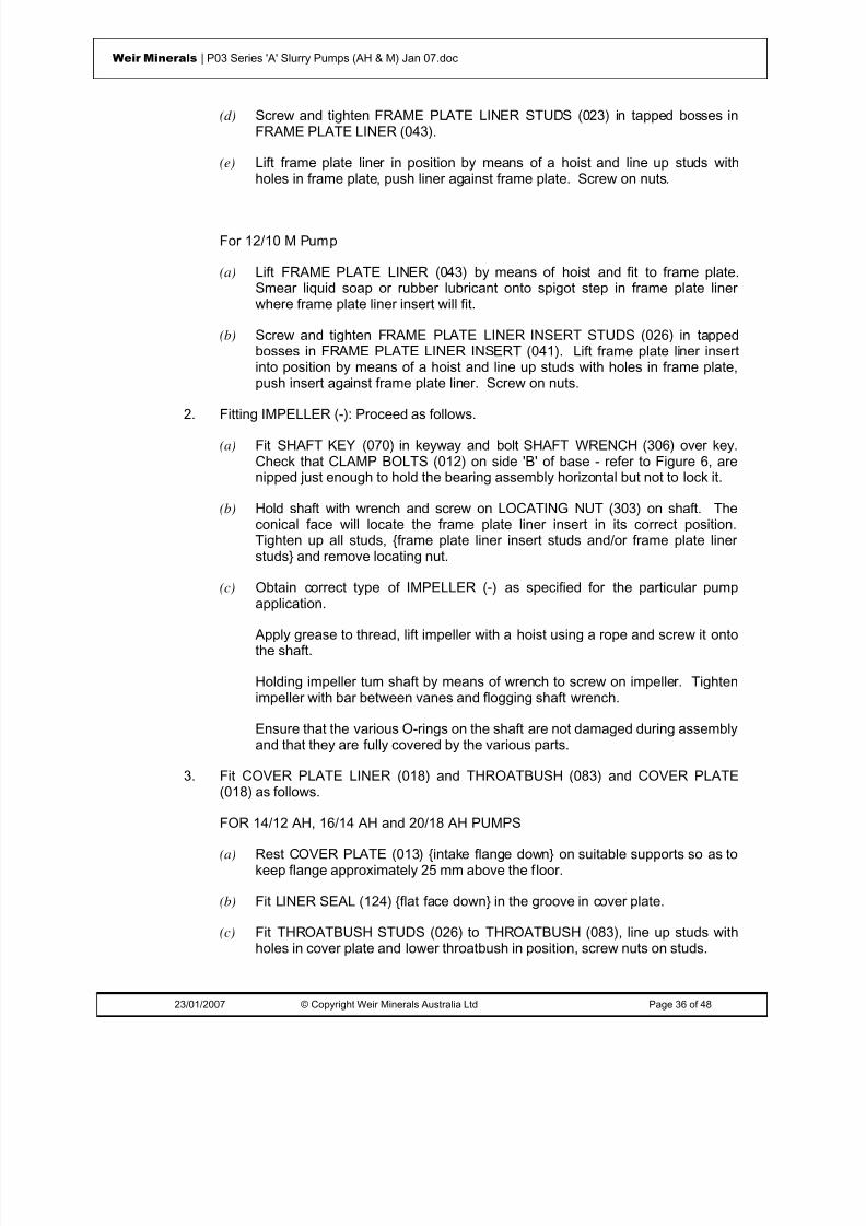
8/15/2019 r1_OF 71289_6 FF-AHF
http://slidepdf.com/reader/full/r1of-712896-ff-ahf 77/333
23/01/2007 © Copyright Weir Minerals Australia Ltd Page 36 of 48
Weir Minerals | P03 Series 'A' Slurry Pumps (AH & M) Jan 07.doc
(d) Screw and tighten FRAME PLATE LINER STUDS (023) in tapped bosses inFRAME PLATE LINER (043).
(e) Lift frame plate liner in position by means of a hoist and line up studs withholes in frame plate, push liner against frame plate. Screw on nuts.
For 12/10 M Pump
(a) Lift FRAME PLATE LINER (043) by means of hoist and fit to frame plate.Smear liquid soap or rubber lubricant onto spigot step in frame plate linerwhere frame plate liner insert will fit.
(b) Screw and tighten FRAME PLATE LINER INSERT STUDS (026) in tappedbosses in FRAME PLATE LINER INSERT (041). Lift frame plate liner insertinto position by means of a hoist and line up studs with holes in frame plate,push insert against frame plate liner. Screw on nuts.
2. Fitting IMPELLER (-): Proceed as follows.
(a) Fit SHAFT KEY (070) in keyway and bolt SHAFT WRENCH (306) over key.Check that CLAMP BOLTS (012) on side 'B' of base - refer to Figure 6, arenipped just enough to hold the bearing assembly horizontal but not to lock it.
(b) Hold shaft with wrench and screw on LOCATING NUT (303) on shaft. Theconical face will locate the frame plate liner insert in its correct position.Tighten up all studs, {frame plate liner insert studs and/or frame plate linerstuds} and remove locating nut.
(c) Obtain correct type of IMPELLER (-) as specified for the particular pumpapplication.
Apply grease to thread, lift impeller with a hoist using a rope and screw it ontothe shaft.
Holding impeller turn shaft by means of wrench to screw on impeller. Tightenimpeller with bar between vanes and flogging shaft wrench.
Ensure that the various O-rings on the shaft are not damaged during assemblyand that they are fully covered by the various parts.
3. Fit COVER PLATE LINER (018) and THROATBUSH (083) and COVER PLATE(018) as follows.
FOR 14/12 AH, 16/14 AH and 20/18 AH PUMPS
(a) Rest COVER PLATE (013) {intake flange down} on suitable supports so as tokeep flange approximately 25 mm above the floor.
(b) Fit LINER SEAL (124) {flat face down} in the groove in cover plate.
(c) Fit THROATBUSH STUDS (026) to THROATBUSH (083), line up studs withholes in cover plate and lower throatbush in position, screw nuts on studs.

8/15/2019 r1_OF 71289_6 FF-AHF
http://slidepdf.com/reader/full/r1of-712896-ff-ahf 78/333
23/01/2007 © Copyright Weir Minerals Australia Ltd Page 37 of 48
Weir Minerals | P03 Series 'A' Slurry Pumps (AH & M) Jan 07.doc
(d) Screw STUDS (023) in COVER PLATE LINER (018) tapped bosses, fit liner incover plate and ensure that studs line up with respective holes in cover plate,screw nuts on studs and tighten.
Tighten THROATBUSH STUDS (026).
FOR 12/10 M PUMP
(a) Rest COVER PLATE (013) {intake flange down} on suitable supports so as tokeep flange approximately 25 mm above floor.
Fit COVER PLATE LINER (018) to cover plate and smear liquid soap orrubber lubricant onto spigot step in cover plate liner where throatbush will fit.
(b) Lower THROATBUSH (083) into cover plate and push firmly down to rest oncover plate liner.
(c) Insert COTTERS (085) through slots in neck of cover plate and tap themcarefully and evenly until the throatbush is held firmly in the cover plate.
4. Fit COVER PLATE (013).
Lift cover plate complete with throatbush and cover plate liner and line up holes withCOVER PLATE BOLTS (015) already in frame plate.
Note : Large cover plates are provided with radially tapped holes for eye bolts tofacilitate lifting.
Check all liner stud nuts and throatbush cotters for tightness.
Screw nuts on cover plate bolts and torque evenly to the value given in Table 1.
5. Depending on the method used to assemble the gland components, complete theassembly of gland parts in the stuffing box or expeller ring by following the relevantinstructions in section on Seal Assembly.
6. For pumps fitted with Warman Mechanical Seals, assembly of the remaining partsand header tank etc should now be completed.
7. Pump is now ready for fitting of joint rings and impeller adjustment. Refer tosections on Assembled Pump - Fitting Joint Rings and Impeller Adjustmentrespectively.

8/15/2019 r1_OF 71289_6 FF-AHF
http://slidepdf.com/reader/full/r1of-712896-ff-ahf 79/333

8/15/2019 r1_OF 71289_6 FF-AHF
http://slidepdf.com/reader/full/r1of-712896-ff-ahf 80/333
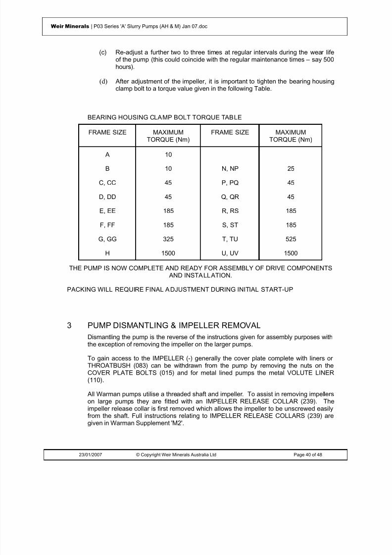
8/15/2019 r1_OF 71289_6 FF-AHF
http://slidepdf.com/reader/full/r1of-712896-ff-ahf 81/333
23/01/2007 © Copyright Weir Minerals Australia Ltd Page 40 of 48
Weir Minerals | P03 Series 'A' Slurry Pumps (AH & M) Jan 07.doc
(c) Re-adjust a further two to three times at regular intervals during the wear lifeof the pump (this could coincide with the regular maintenance times – say 500hours).
(d) After adjustment of the impeller, it is important to tighten the bearing housingclamp bolt to a torque value given in the following Table.
BEARING HOUSING CLAMP BOLT TORQUE TABLE
FRAME SIZE MAXIMUMTORQUE (Nm)
FRAME SIZE MAXIMUMTORQUE (Nm)
A 10
B 10 N, NP 25
C, CC 45 P, PQ 45D, DD 45 Q, QR 45
E, EE 185 R, RS 185
F, FF 185 S, ST 185
G, GG 325 T, TU 525
H 1500 U, UV 1500
THE PUMP IS NOW COMPLETE AND READY FOR ASSEMBLY OF DRIVE COMPONENTS
AND INSTALLATION.PACKING WILL REQUIRE FINAL ADJUSTMENT DURING INITIAL START-UP
3 PUMP DISMANTLING & IMPELLER REMOVALDismantling the pump is the reverse of the instructions given for assembly purposes withthe exception of removing the impeller on the larger pumps.
To gain access to the IMPELLER (-) generally the cover plate complete with liners orTHROATBUSH (083) can be withdrawn from the pump by removing the nuts on theCOVER PLATE BOLTS (015) and for metal lined pumps the metal VOLUTE LINER(110).
All Warman pumps utilise a threaded shaft and impeller. To assist in removing impellerson large pumps they are fitted with an IMPELLER RELEASE COLLAR (239). Theimpeller release collar is first removed which allows the impeller to be unscrewed easilyfrom the shaft. Full instructions relating to IMPELLER RELEASE COLLARS (239) aregiven in Warman Supplement 'M2'.

8/15/2019 r1_OF 71289_6 FF-AHF
http://slidepdf.com/reader/full/r1of-712896-ff-ahf 82/333
23/01/2007 © Copyright Weir Minerals Australia Ltd Page 41 of 48
Weir Minerals | P03 Series 'A' Slurry Pumps (AH & M) Jan 07.doc
4 PRODUCT MODIFICATION ADVICE (PMA)This manual has been compiled from the latest information and revisions regardingWarman TYPE 'AH' pump fit-up. Over time improvements have been incorporated intocertain pumps and advice distributed in the form of Product Modification Advice (PMA)sheets. Listed below are the relevant PMA's for TYPE 'AH' pumps. If further informationis required on any of these topics please contact your nearest Weir Warman Office.
PMA No ISSUED DATE DESCRIPTION
PMA -110-1 Aug 76 Modification to existing 12/10 AH Cover Platesfor fitting redesigned moulded liners
PMA-110-3 Mar 77 Correction to Frame Plate Liner Part Numbers.
PMA-110-4 Aug 78 Conversion of FAM Frame pumps Shaft Assembly with Release Collar
PMA-110-9 May 80 16/14 G-AH modification of Gland &Centrifugal Seal.
PMA-110-11 May 80 D-AH pumps: Modification of Centrifugal Seal
PMA-110-12 Dec 80 Provision of holding the Volute Liner in positionduring Assembly - pump 6/4 AH, 8/6 AH, 10/8
M and 12/10 M
PMA-110-13 Jan 81 List of interchangeable Imperial and Metric
Parts.PMA-110-15 Jun 82 Change of Designations of some Series 'A'
Pumps.
PMA-110-18 Oct 82 12/10 AH pump: Modification of method ofretaining Throatbush
PMA-100-19 Mar 83 Securing the Frame Plate Liner Insert Bolt tothe Liner Insert.
PMA-110-20 Sep 83 16/14 AH Pump: Modification of method ofretaining Throatbush.
PMA-110-26 Mar 85 Discharge Joint Rings (132)
PMA-110-27 May 85 Frame Plate Liner Inserts: Change from Boltsto Studs.
PMA-110-28 Sep 85 Improved method of fixing F4041

8/15/2019 r1_OF 71289_6 FF-AHF
http://slidepdf.com/reader/full/r1of-712896-ff-ahf 83/333
23/01/2007 © Copyright Weir Minerals Australia Ltd Page 42 of 48
Weir Minerals | P03 Series 'A' Slurry Pumps (AH & M) Jan 07.doc
PMA No ISSUED DATE DESCRIPTION
PMA-110-29 Sep 85 Improved method of fixing F8041
PMA-110-30 Sep 85 Improved method of fixing F10041
PMA-110-31 Jan 86 Bearing Assembly END COVERS (024)
PMA-110-38 Oct 87 Split type Lantern Ring
PMA-110-39 Aug 87 Expeller EAM028
PMA-110-40 Apr 88 Frame Plate Liner Insert Studs
PMA-110-41 Sep 88 Expeller CAM028 & 'O'-ring D064
PMA-110-48 Dec 89 Bearing Assembly
PMA-110-53 May 93 Rubber Impeller with metal boss cap
PMA-110-59 Aug 91 10/8 AH Method of retaining throatbush
PMA-110-61 Sep 91 6/4 D-AH & 6/4 E-AH Bearing Assembly
PMA-110-63 Jan 92 Bolts & Tee slots for fixing Volute
PMA-110-64 Apr 92 8/6 F-AH modified impeller MK119402C
PMA-110-65 Jun 92 Modification on the reduced eye impellers
PMA-110-66 Jun 92 Change Liner Part No.
PMA-110-69 Aug 92 Change high efficiency impeller & throatbushPart No.
PMA-110-70 Aug 92 10/8M impeller F8145HE2 Part No wasMK124934A
PMA-110-84 Oct 92 Change Volutes Part No
PMA-110-86 Nov 92 Change impeller Part No
PMA-110-87 Nov 92 Change 16/14 G-AH impeller Part No

8/15/2019 r1_OF 71289_6 FF-AHF
http://slidepdf.com/reader/full/r1of-712896-ff-ahf 84/333
23/01/2007 © Copyright Weir Minerals Australia Ltd Page 43 of 48
Weir Minerals | P03 Series 'A' Slurry Pumps (AH & M) Jan 07.doc
BASIC PART NUMBERS & PARTS LIST
A
ADJUSTING SCREW (001) 8, 28, 41
B
BASE (003) 8, 40
BEARING ASSEMBLY (005) 8, 24
BOLTS (040) 30
C
CLAMP BOLTS (012) 8, 27, 30, 35, 38
CLAMP BRACKET (022) 15
CLAMP BRACKET SET SCREW 15
CLAMP WASHER (011) 8
COTTERS (085) 31, 35, 39
COVER PLATE (013) 28, 31, 33, 35, 36, 39
COVER PLATE (018) 38
COVER PLATE BOLTS (015) 10, 28, 31, 33, 36, 39, 42
COVER PLATE LINER (017) 33
COVER PLATE LINER (018) 35, 36, 38, 39
COVER PLATE LINER STUDS (023) 36
D
DISCHARGE JOINT RING (132) 40
E
END COVER (024) 24
END COVER (024-50) 24
EXPELLER (028) 18, 21, 22, 24
EXPELLER RING (029) 20, 22
EXPELLER RING (029R) 23
EXPELLER RING LIFTING BEAM (310) 22
EXPELLER RING STUDS (079) 23EYE BOLTS (-) 9
F
FRAME PLATE (032) 9
FRAME PLATE BOLTS (034) 9
FRAME PLATE LINER (036) 32, 34
FRAME PLATE LINER (043) 37, 38
FRAME PLATE LINER INSERT (041) 27, 28, 30, 37, 38
FRAME PLATE LINER INSERT STUDS (026) 37, 38
FRAME PLATE LINER STUDS (023) 38
FRAME PLATE STUDS (039) 9
G
GLAND (044) 14, 15, 21, 22
GLAND BOLTS (045) 14, 15, 21, 22
GLAND CLAMP BOLTS (126) 14, 15, 21, 22
GREASE CUP (-) 21, 22
GREASE CUP ADAPTOR (138) 21, 22
I
IMPELLER (-) 15, 27, 28, 30, 33, 34, 35, 38, 42
IMPELLER RELEASE COLLAR (239) 14, 15, 21, 22, 23,
42, 43
INTAKE JOINT RING (060) 40
K
KEEPER PLATES (081) 10, 31
L
LABYRINTH (062) 8, 11, 14, 15, 17, 21, 23
LANTERN RESTRICTOR (118) 14, 15
LANTERN RESTRICTORS (118-1) 11
LANTERN RING (063) 14, 15, 20, 22
LANTERN RING (063R) 23
LIFTING PLATE (310) 14, 21
LIFTING TUBE (302) 30, 37
LINER SEAL (124) 35, 39
LIP SEAL GLAND (241) 23
LIP SEALS (090) 23
LOCATING NUT (303) 30, 34, 38
N
NECK RING (067) 14, 15, 20, 22
O
O-RING (109 or 064) 21, 22, 24, 30

8/15/2019 r1_OF 71289_6 FF-AHF
http://slidepdf.com/reader/full/r1of-712896-ff-ahf 85/333
23/01/2007 © Copyright Weir Minerals Australia Ltd Page 44 of 48
Weir Minerals | P03 Series 'A' Slurry Pumps (AH & M) Jan 07.doc
P
PACKING (111) 20
PACKING RING (111) 14, 15, 20, 22
S
SEAL RING (122) 27, 29
SHAFT (073) 8
SHAFT KEY (070) 27, 28, 30, 33, 34, 38
SHAFT SLEEVE (075 or 076) 14
SHAFT SLEEVE (075) 20, 21, 22, 23, 24
SHAFT SPACER (117) 18
SHAFT WRENCH (306) 27, 28, 30, 33, 34, 38
STUDS (023) 33, 39
STUDS (026) 30, 33, 34, 35
STUFFING BOX (078) 13, 15
STUFFING BOX LIFTING PLATE (310) 15
T
THROATBUSH (083) 31, 35, 36, 38, 39, 42
THROATBUSH STUDS (026) 31, 36, 39
V
VOLUTE FRAME SEAL (125) 27, 28
VOLUTE LIFTING BEAM (304) 31
VOLUTE LINER (110) 10, 28, 31, 42
VOLUTE LINER SEAL (124 or 125) 27
VOLUTE LINER SEAL (124) 27, 30, 31, 36, 37

8/15/2019 r1_OF 71289_6 FF-AHF
http://slidepdf.com/reader/full/r1of-712896-ff-ahf 86/333
23/01/2007 © Copyright Weir Minerals Australia Ltd Page 45 of 48
Weir Minerals | P03 Series 'A' Slurry Pumps (AH & M) Jan 07.doc
APPENDIX
Fitting Elastomer Cover Plate Liner and Throatbush
These instructions apply to pumps which have an integral volute seal as part of the cover plateliner. This applies to the following pumps: 10/8 AH, 10/8 M and 8/6 AH.
While there are a number of different methods available, the following method eases assemblyparticularly if super thick elastomer liners are being fitted or studs are utilised to hold thethroatbush into the cover plate (ie no cotters).
Figure 1
1. For pumps with throatbush studs only.
Fit the cover plate liner to the cover plate and mark a line on the outside of the liner so thatthe throatbush studs will line up on final assembly with the holes in the cover plate.
2. Support the cover plate liner, seal side up with blocks of timber.
3. Lubricate outside of throatbush and cover plate seal with rubber lubricant or similar.

8/15/2019 r1_OF 71289_6 FF-AHF
http://slidepdf.com/reader/full/r1of-712896-ff-ahf 87/333
23/01/2007 © Copyright Weir Minerals Australia Ltd Page 46 of 48
Weir Minerals | P03 Series 'A' Slurry Pumps (AH & M) Jan 07.doc
Figure 2
4. Lift throatbush on top of liner and push one side of the throatbush underneath the seal lip.
5. Use levers to lift the seal working around the edge of the throatbush. Levers pluspressure on top of the throatbush will allow the throatbush to slip into place on the taper.
Figure 3
6. Rotate throatbush if required to align marks for stud near the cutwater.
Figure 4

8/15/2019 r1_OF 71289_6 FF-AHF
http://slidepdf.com/reader/full/r1of-712896-ff-ahf 88/333
23/01/2007 © Copyright Weir Minerals Australia Ltd Page 47 of 48
Weir Minerals | P03 Series 'A' Slurry Pumps (AH & M) Jan 07.doc
Figure 5
7. Lower cover plate over liner and throatbush till throatbush studs protrude through holes.
8. Push down on cover plate if required.
9. Fit nuts to the throatbush studs and tighten.
Figure 6
10. Lift cover plate vertically and knock liner into cover plate with a rubber mallet if required.
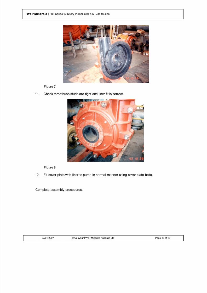
8/15/2019 r1_OF 71289_6 FF-AHF
http://slidepdf.com/reader/full/r1of-712896-ff-ahf 89/333
23/01/2007 © Copyright Weir Minerals Australia Ltd Page 48 of 48
Weir Minerals | P03 Series 'A' Slurry Pumps (AH & M) Jan 07.doc
Figure 7
11. Check throatbush studs are tight and liner fit is correct.
Figure 8
12. Fit cover plate with liner to pump in normal manner using cover plate bolts.
Complete assembly procedures.
8/15/2019 r1_OF 71289_6 FF-AHF
http://slidepdf.com/reader/full/r1of-712896-ff-ahf 90/333
© Weir Minerals Australia Ltd 2007. Weir Minerals Australia Ltd. is the owner of the Copyright in this document. The document and its text, images, diagrams, data andinformation it contains must not be copied or reproduced in whole or in part, in any form or by any means, without the prior written consent of Weir Minerals Australia Ltd.
Office of origin : Pump Technology Centre, Artarmon Reference : Pump Manuals
Date : 22 January 2007 Last Issued: July 2005
Assembly & MaintenanceInstructionsSupplement ‘BA3’Modified Basic Bearings Assembly (Basic Number 005)(Frame Sizes CC, DD, EE, FF & GG)

8/15/2019 r1_OF 71289_6 FF-AHF
http://slidepdf.com/reader/full/r1of-712896-ff-ahf 91/333
23/01/2007 © Copyright Weir Minerals Australia Ltd Page 2 of 20
Weir Minerals | BA3 Modified Basic Bearing Assembly Jan 07.doc
WarningsPersonnel injury and / or equipment damage could result from not observing the followingIMPORTANT SAFETY INFORMATION
. • A pump is both a pressure vessel and a piece of rotating equipment . All standard safetyprecautions for such equipment should be followed before and during installation, operation andmaintenance.
• For auxiliary equipment (motors, belt drives, couplings, gear reducers, variable speed drives,mechanical seals, etc) all related safety precautions should be followed and appropriateinstruction manuals consulted before and during installation, operation, adjustment andmaintenance.
• All guards for rotating equipment must be correctly fitted before operating the pump includingguards temporarily removed for gland inspection and adjustment. Seal guards should not be
removed or opened while the pump is running. Personal injury may result from contact withrotating parts, seal leakage or spray.•
Driver rotation must be checked before belts or couplings are connected.•
Pumps must not be operated at low or zero flow conditions for prolonged periods, or underany circumstances that could cause the pumping liquid to vaporise. Personnel injury andequipment damage could result from the high temperature and pressure created.
• Pumps must be used only within their allowable limits of pressure, temperature and speed.These limits are dependent on the pump type, configuration and materials used.
• Do not apply heat to t he impeller boss or nose in an effort to loosen the impeller thread priorto impeller removal. Personnel injury and equipment damage could result from the impellershattering or exploding when the heat is applied.
• Do not feed very hot or very cold liquid into a pump which is at ambient temperature.Thermal shock may cause the pump casing to crack.
• LIFTING of components
• Tapped holes (for eye bolts) and lugs (for lifting shackles) on Warman pumps are forlifting Individual parts only .
• Lifting devices of adequate capacity must be used wherever they are required to beused.
• Safe workshop practices should be applied during all assembly and maintenance work.• Personnel must never work under suspended loads.•
The pump must be fully isolated before any maintenance work, inspection or troubleshootinginvolving work on sections which are potentially pressurised (eg casing, gland, connectedpipework) or involving work on the mechanical drive system (eg shaft, bearing assembly,coupling). Power to the electric motor must be isolated and tagged out. It must be proven thatthe intake and discharge openings are totally isolated from all potentially pressurisedconnections and that they are and can only be exposed to atmospheric pressure.
•

8/15/2019 r1_OF 71289_6 FF-AHF
http://slidepdf.com/reader/full/r1of-712896-ff-ahf 92/333

8/15/2019 r1_OF 71289_6 FF-AHF
http://slidepdf.com/reader/full/r1of-712896-ff-ahf 93/333
23/01/2007 © Copyright Weir Minerals Australia Ltd Page 4 of 20
Weir Minerals | BA3 Modified Basic Bearing Assembly Jan 07.doc
ISSUED: JA NUARY 2007 LA ST ISSUE: JULY 2005
WARMAN PUMPS ASSEMBLY AND MAINTENANCE INSTRUCTIONS
SUPPLEMENT ‘BA3’MODIFIED BASIC BEARING ASSEMBLIES
(FRAME SIZES CC, DD, EE, FF & GG)
CONTENTS
WARNINGS 2
CONTENTS 4
1 INTRODUCTION 6
2 ADVANTAGES AND USES OF MODIFIED BASIC BEARING ASSEMBLIES 6
3 SUBSTITUTION OF MODIFIED BASIC BEARING ASSEMBLIES IN PLACE OFBASIC BEARING ASSEMBLIES 6
4 PARTS IDENTIFICATION 7
5 BEARING LUBRICATION 8
6 LABYRINTH GREASE PURGING 10
7 ASSEMBLY INSTRUCTIONS 11
Fitting of Drive End Inner Bearing and Pump End Bearing - See Figure 1 12 Fitting of Drive End Outer Ring Bearing to Bearing Housing - See Figure 2 13 Fitting Shaft to Bearing Housing - See Figure 3 14 Fitting Labyrinths, Piston Rings, Bearing Seal and Locknut - See Figure 4 16
8 FITTING IMPELLER RELEASE COLLAR - (FOR FF AND GG ASSEMBLIES) 16
9 CHECKING BEARING FITTED END PLAY 17
10 TESTING 18
11 MAINTENANCE: STAND-BY PUMPS 18
8/15/2019 r1_OF 71289_6 FF-AHF
http://slidepdf.com/reader/full/r1of-712896-ff-ahf 94/333
23/01/2007 © Copyright Weir Minerals Australia Ltd Page 5 of 20
Weir Minerals | BA3 Modified Basic Bearing Assembly Jan 07.doc
BASIC NUMBERS AND PARTS LIST 19
RECOMMENDED BEARING GREASE 20
8/15/2019 r1_OF 71289_6 FF-AHF
http://slidepdf.com/reader/full/r1of-712896-ff-ahf 95/333
23/01/2007 © Copyright Weir Minerals Australia Ltd Page 6 of 20
Weir Minerals | BA3 Modified Basic Bearing Assembly Jan 07.doc
1 INTRODUCTION
Supplement 'BA3' should be read in conjunction with the appropriate Assembly andMaintenance Instruction Manual Supplement for the particular TYPE of Warman Pumpwhen Modified Basic Bearing Assemblies (as denoted by a double letter for frame size -eg 6/4 EE-AH; 10/8 FF-M) are used in place of the standard Basic Bearing Assembliesviz. C, D, E, F and G.
2 ADVANTAGES AND USES OF MODIFIED BASIC BEARING ASSEMBLIES
The Basic Bearing Assemblies have been in use for many years and are still consideredto be the standard assembly with capacity to meet most requirements. However, for the
duties which require a higher bearing capacity such as for large belt drives, multi-stagepumping (increased thrust loadings onto bearings) or in some cases where the pump isoperating at or near its maximum speed and power, then the extra capacity of themodified basic bearing assemblies will give significantly higher bearing life than a basicbearing assembly and therefore less down time and maintenance costs.
The modified basic bearing assemblies are also suitable for certain duties "betweenframes" such as a situation where the basic F-frame capacity is too low but the basic G-frame is too high and represents a much higher capital investment. In such a case themodified basic FF-frame may suit the duty with its higher capacity (higher than F but lessthan G).
Other features of modified basic assemblies are:
(a) All threaded components are metric
(b) The drive end shaft extension diameter is metric and metric keys are used.
(c) No setting or adjusting of bearing end play is required such as is necessary onWarman Basic Bearing Assemblies. Modified basic bearing assemblies are fittedwith a two row tapered roller bearing at the pump end. These two row bearings arefactory set with the required amount of end play. Consequently no shimming duringassembly is required.
(d) Grease purged labyrinths are standard to assist in exclusion of dirt and moisturefrom assemblies.
3 SUBSTITUTION OF MODIFIED BASIC BEARING ASSEMBLIES INPLACE OF BASIC BEARING ASSEMBLIES
Modified basic bearing assemblies (Basic Part Number 005) are dimensionally the samein silhouette as the equivalent basic bearing assembly and hence can be substituteddirectly for a basic bearing assembly without changing base, sleeves, impeller etc.however, the drive end shaft diameter and keyway are different. A simple change oftaper lock is possibly all that is required.
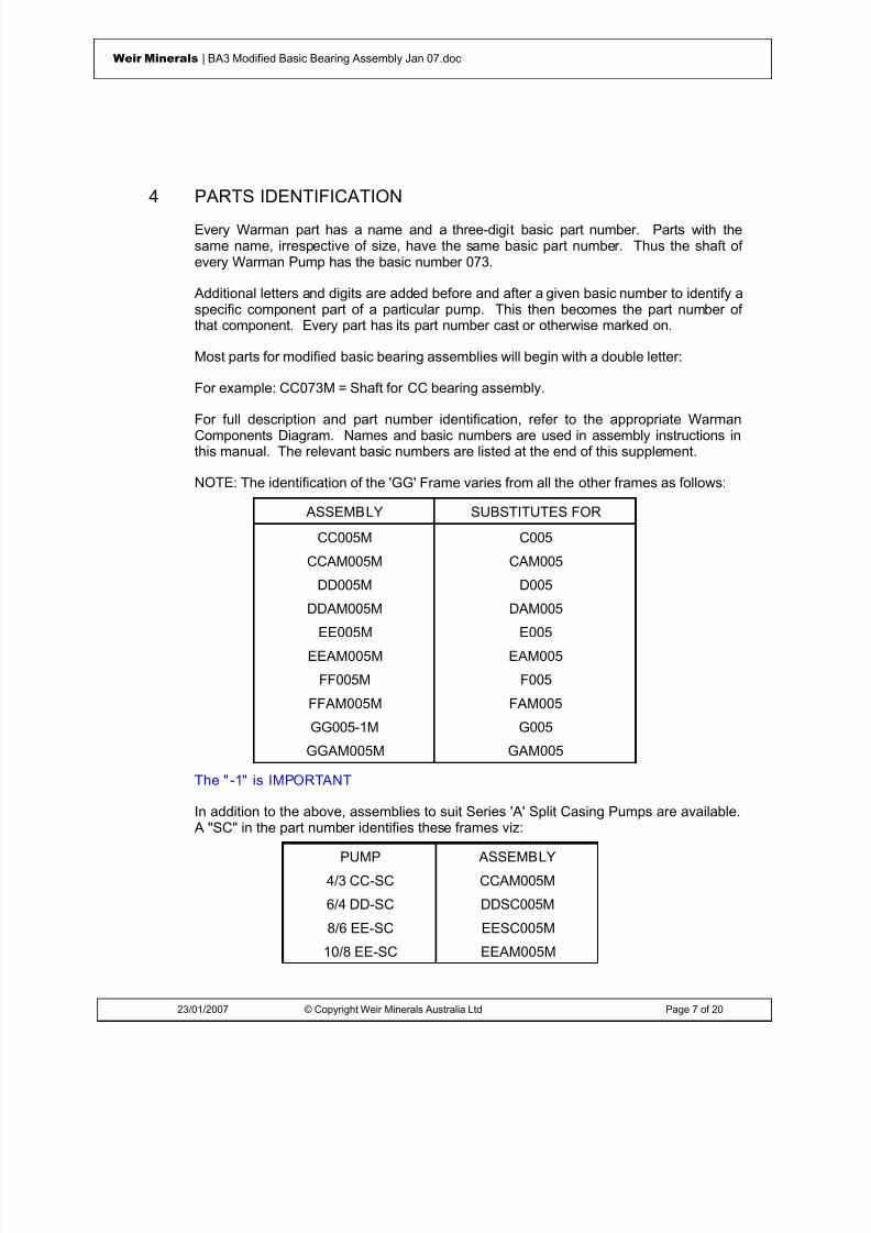
8/15/2019 r1_OF 71289_6 FF-AHF
http://slidepdf.com/reader/full/r1of-712896-ff-ahf 96/333
23/01/2007 © Copyright Weir Minerals Australia Ltd Page 7 of 20
Weir Minerals | BA3 Modified Basic Bearing Assembly Jan 07.doc
4 PARTS IDENTIFICATIONEvery Warman part has a name and a three-digit basic part number. Parts with thesame name, irrespective of size, have the same basic part number. Thus the shaft ofevery Warman Pump has the basic number 073.
Additional letters and digits are added before and after a given basic number to identify aspecific component part of a particular pump. This then becomes the part number ofthat component. Every part has its part number cast or otherwise marked on.
Most parts for modified basic bearing assemblies will begin with a double letter:
For example: CC073M = Shaft for CC bearing assembly.
For full description and part number identification, refer to the appropriate WarmanComponents Diagram. Names and basic numbers are used in assembly instructions inthis manual. The relevant basic numbers are listed at the end of this supplement.
NOTE : The identification of the 'GG' Frame varies from all the other frames as follows:
ASSEMBLY SUBSTITUTES FOR
CC005M C005
CCAM005M CAM005
DD005M D005
DDAM005M DAM005
EE005M E005
EEAM005M EAM005
FF005M F005
FFAM005M FAM005
GG005-1M G005
GGAM005M GAM005
The " -1" is IMPORTANT
In addition to the above, assemblies to suit Series 'A' Split Casing Pumps are available. A "SC" in the part number identifies these frames viz:
PUMP ASSEMBLY
4/3 CC-SC CCAM005M
6/4 DD-SC DDSC005M
8/6 EE-SC EESC005M
10/8 EE-SC EEAM005M

8/15/2019 r1_OF 71289_6 FF-AHF
http://slidepdf.com/reader/full/r1of-712896-ff-ahf 97/333
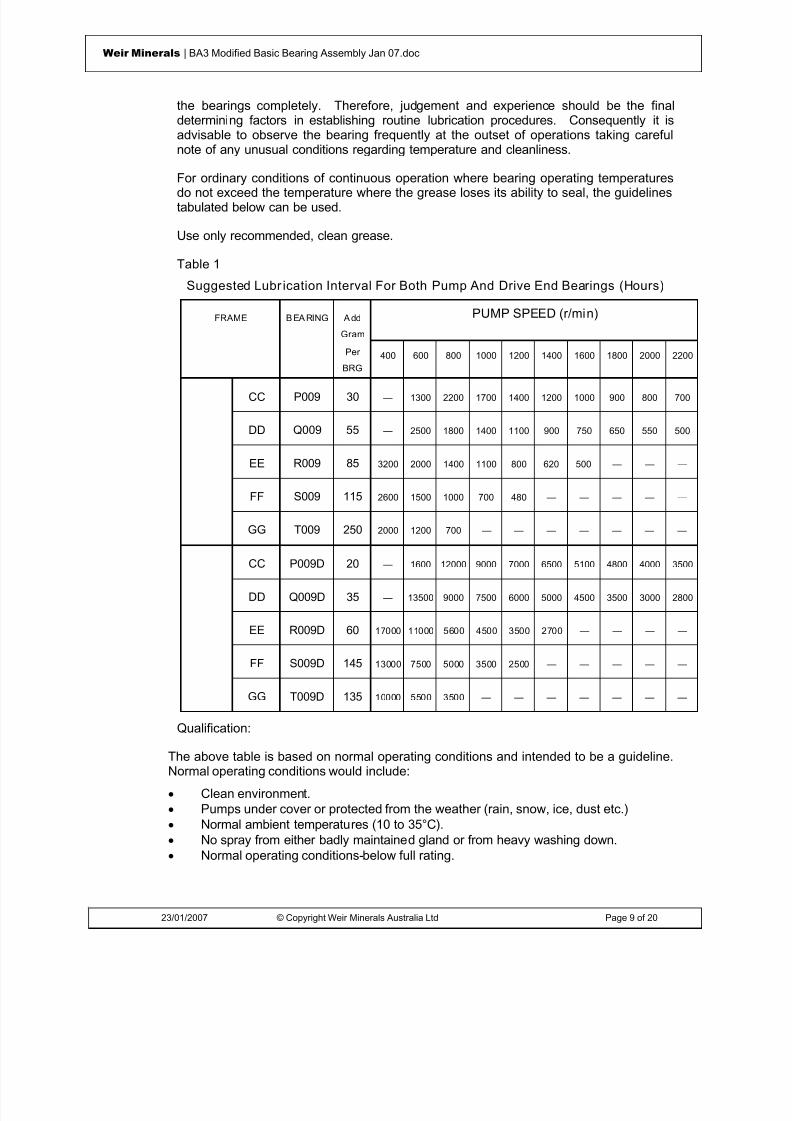
8/15/2019 r1_OF 71289_6 FF-AHF
http://slidepdf.com/reader/full/r1of-712896-ff-ahf 98/333
23/01/2007 © Copyright Weir Minerals Australia Ltd Page 9 of 20
Weir Minerals | BA3 Modified Basic Bearing Assembly Jan 07.doc
the bearings completely. Therefore, judgement and experience should be the finaldetermining factors in establishing routine lubrication procedures. Consequently it isadvisable to observe the bearing frequently at the outset of operations taking carefulnote of any unusual conditions regarding temperature and cleanliness.
For ordinary conditions of continuous operation where bearing operating temperaturesdo not exceed the temperature where the grease loses its ability to seal, the guidelinestabulated below can be used.
Use only recommended, clean grease.
Table 1
Suggested Lubr ication Interval For Both Pump And Drive End Bearings (Hours)
FRAME B EA RING A dd
Gram
PUMP SPEED (r/min)
Per
BRG 400 600 800 1000 1200 1400 1600 1800 2000 2200
CC P009 30 — 1300 2200 1700 1400 1200 1000 900 800 700
DD Q009 55 — 2500 1800 1400 1100 900 750 650 550 500
EE R009 85 3200 2000 1400 1100 800 620 500 — — —
FF S009 115 2600 1500 1000 700 480 — — — — —
GG T009 250 2000 1200 700 — — — — — — —
CC P009D 20 — 1600 12000 9000 7000 6500 5100 4800 4000 3500
DD Q009D 35 — 13500 9000 7500 6000 5000 4500 3500 3000 2800
EE R009D 60 17000 11000 5600 4500 3500 2700 — — — —
FF S009D 145 13000 7500 5000 3500 2500 — — — — —
GG T009D 135 10000 5500 3500 — — — — — — —
Qualification:
The above table is based on normal operating conditions and intended to be a guideline.Normal operating conditions would include:• Clean environment.• Pumps under cover or protected from the weather (rain, snow, ice, dust etc.)• Normal ambient temperatures (10 to 35°C).• No spray from either badly maintained gland or from heavy washing down.• Normal operating conditions-below full rating.

8/15/2019 r1_OF 71289_6 FF-AHF
http://slidepdf.com/reader/full/r1of-712896-ff-ahf 99/333
23/01/2007 © Copyright Weir Minerals Australia Ltd Page 10 of 20
Weir Minerals | BA3 Modified Basic Bearing Assembly Jan 07.doc
• Tabulated figures are based on bearing temperatures of 70°C measured at theouter ring. Intervals should be halved for every 15°C increase above 70°C, butthe maximum permissible operating temperature for the grease should obviouslynot be exceeded.
Very dirty or damp atmospheric conditions or conditions that varied from those listed
above would require that the recommendations be stepped up to a level that preventscontaminants from entering the bearings.
Initial Grease Fill:
The recommended initial quantities of grease to be used for each bearing is given on theattached Modified Basic Bearing Assemblies information sheet.
6 LABYRINTH GREASE PURGING
Less contaminants entering the bearing assembly will result in longer bearing life andultimately a cost saving. Therefore careful attention paid to labyrinth grease purging is anessential maintenance requirement.
The bearings cannot be over greased as approximately 95% of every shot of greaseentering the grease purge nipple exits at the labyrinth and only the remaining 5% entersthe bearing assembly.
Suggested intervals for grease purging of the labyrinths, based on normal operatingconditions are tabulated below and intended as a guide. Very dirty or damp atmosphericconditions would require that the recommendations be stepped up to a level that preventscontaminants from entering the bearing assembly. The colour and condition of the purgedgrease may be used as a guide to varying the intervals.
Recommended Intervals For Labyrinth Grease Purging
Continuous (24h)Operation
16h OperationPer Day
8h Operation PerDay
Pump End Labyrinth 4 shots every 12hours *
4 shots daily 2 shots daily
Drive End Labyrinth 4 shots every 120hours
4 shots weekly 2 shots weekly
* Shots are from a standard hand operated grease gun.
Type '-10' Bearing Assembly Sealing Arrangement
Type '-10' is Warman standard bearing assembly sealing arrangement and is patentedworldwide. The design uses an additional V-ring seal and larger flinger-labyrintharrangement as further protection against grit and moisture penetrating the bearing. Toimprove the sealing of the pump and drive ends of bearing assemblies, a radially drilledhole in the end covers allows grease to be fed into the space between the piston ringsrather than directly into the labyrinth. The grease forms a pressurised barrier between thetwo piston rings. The small amount of grease that enters the bearings will assist in theirlubrication and the grease that escapes outwards together with the centrifuging effectwhen the pump is running will keep the labyrinth purged of grit and moisture. To improve

8/15/2019 r1_OF 71289_6 FF-AHF
http://slidepdf.com/reader/full/r1of-712896-ff-ahf 100/333
23/01/2007 © Copyright Weir Minerals Australia Ltd Page 11 of 20
Weir Minerals | BA3 Modified Basic Bearing Assembly Jan 07.doc
the purging, particularly on the pump end of the bearing assembly the standard labyrinthgrease purging nipple can be replaced with an automatic grease feeder (say threemonths capacity on smaller frames and one month capacity on the larger frames).
The type of grease used for labyrinth sealing should be the same as that used forlubricating the bearings.
If an automatic grease feeder is used it will only be necessary to check at regular intervalsthat it has not fully discharged. If grease nipples are utilised, the guidelines as tabulatedabove should be followed.
Note: '-10' End Covers are supplied as standard and are available as Retrofit Kits.
7 ASSEMBLY INSTRUCTIONS
When bearing assemblies have been dismantled for complete overhaul, all parts shouldbe closely inspected and new parts checked for correct identification.
Used parts being replaced should be thoroughly cleaned and repainted where required.Mating faces and spigots should be free of rust, dirt and burrs and given a coat of greasebefore they are fitted together to assist future overhaul.
It is preferable to renew small bolts and set screws during overhaul and all threads shouldbe coated with graphite grease before assembly. It is also recommended that all rubberseals should be replaced during major overhauls as rubber tends to harden and seals losetheir effectiveness .
Figure 1
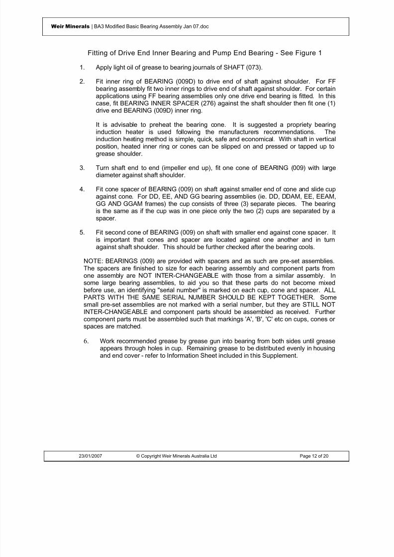
8/15/2019 r1_OF 71289_6 FF-AHF
http://slidepdf.com/reader/full/r1of-712896-ff-ahf 101/333
23/01/2007 © Copyright Weir Minerals Australia Ltd Page 12 of 20
Weir Minerals | BA3 Modified Basic Bearing Assembly Jan 07.doc
Fitting of Drive End Inner Bearing and Pump End Bearing - See Figure 1
1. Apply light oil of grease to bearing journals of SHAFT (073).
2. Fit inner ring of BEARING (009D) to drive end of shaft against shoulder. For FFbearing assembly fit two inner rings to drive end of shaft against shoulder. For certainapplications using FF bearing assemblies only one drive end bearing is fitted. In thiscase, fit BEARING INNER SPACER (276) against the shaft shoulder then fit one (1)drive end BEARING (009D) inner ring.
It is advisable to preheat the bearing cone. It is suggested a propriety bearinginduction heater is used following the manufacturers recommendations. Theinduction heating method is simple, quick, safe and economical. With shaft in verticalposition, heated inner ring or cones can be slipped on and pressed or tapped up togrease shoulder.
3. Turn shaft end to end (impeller end up), fit one cone of BEARING (009) with largediameter against shaft shoulder.
4. Fit cone spacer of BEARING (009) on shaft against smaller end of cone and slide cupagainst cone. For DD, EE, AND GG bearing assemblies (ie. DD, DDAM, EE, EEAM,GG AND GGAM frames) the cup consists of three (3) separate pieces. The bearingis the same as if the cup was in one piece only the two (2) cups are separated by aspacer.
5. Fit second cone of BEARING (009) on shaft with smaller end against cone spacer. Itis important that cones and spacer are located against one another and in turnagainst shaft shoulder. This should be further checked after the bearing cools.
NOTE: BEARINGS (009) are provided with spacers and as such are pre-set assemblies.The spacers are finished to size for each bearing assembly and component parts fromone assembly are NOT INTER-CHANGEABLE with those from a similar assembly. Insome large bearing assemblies, to aid you so that these parts do not become mixedbefore use, an identifying "serial number" is marked on each cup, cone and spacer. ALLPARTS WITH THE SAME SERIAL NUMBER SHOULD BE KEPT TOGETHER. Somesmall pre-set assemblies are not marked with a serial number, but they are STILL NOTINTER-CHANGEABLE and component parts should be assembled as received. Furthercomponent parts must be assembled such that markings 'A', 'B', 'C' etc on cups, cones orspaces are matched.
6. Work recommended grease by grease gun into bearing from both sides until greaseappears through holes in cup. Remaining grease to be distributed evenly in housingand end cover - refer to Information Sheet included in this Supplement.

8/15/2019 r1_OF 71289_6 FF-AHF
http://slidepdf.com/reader/full/r1of-712896-ff-ahf 102/333
23/01/2007 © Copyright Weir Minerals Australia Ltd Page 13 of 20
Weir Minerals | BA3 Modified Basic Bearing Assembly Jan 07.doc
Figure 2
Fitting of Drive End Outer Ring Bearing to Bearing Housing - See Figure 2
1. Apply light grease or oil to drive end bore (marked DRIVE END) of BEARINGHOUSING (004).
2. Stand housing with drive end up and fit outer BEARING (009D) and evenly tap it witha soft hammer against grease retainer against housing shoulder. For FF bearingassembly (ie. FF and FFAM frames) fit two outer BEARINGS (009D).
If only one drive end bearing is to be used fit BEARING OUTER SPACER (276)against housing shoulder then fit one (1) drive end outer BEARING (009D).
3. Work recommended bearing grease (refer to Bearing Lubrication) into bearing(s)filling space in bearing. Apply a liberal amount inside housing leaving space betweengrease retaining shoulder in housing and bearing half full. Remaining grease to be
distributed in end cover - refer to Information Sheet included in this Supplement.
4. Place drive end END COVER (024D) with END COVER GASKET (025) in housing,insert END COVER SET SCREWS (027) and tighten evenly.

8/15/2019 r1_OF 71289_6 FF-AHF
http://slidepdf.com/reader/full/r1of-712896-ff-ahf 103/333
23/01/2007 © Copyright Weir Minerals Australia Ltd Page 14 of 20
Weir Minerals | BA3 Modified Basic Bearing Assembly Jan 07.doc
Figure 3
Fitting Shaft t o Bearing Housing - See Figure 31. Place bearing housing on two wooden blocks with fitted end cover down. Clean and
lightly grease bearing bore.
2. Screw SHAFT LIFTING NUT (311) or standard eye bolt into impeller end of shaft andby means of a hoist lift shaft carefully into housing. Tap bearing until it rests againsthousing shoulder.
3. For GG bearing assemblies (GG and GGAM Frames) fit BEARING SLEEVE (008)into bearing housing and tap until it rests against bearing cup.
4. Place END COVER (024) with END COVER GASKET (025) in housing, insert END
COVER SET SCREWS (027) and tighten evenly.

8/15/2019 r1_OF 71289_6 FF-AHF
http://slidepdf.com/reader/full/r1of-712896-ff-ahf 104/333
23/01/2007 © Copyright Weir Minerals Australia Ltd Page 15 of 20
Weir Minerals | BA3 Modified Basic Bearing Assembly Jan 07.doc
Table 2: Fitti ng Of Bearing Seal
FRAME TO LABYRINTH TO END COVER
CC DD
EE
FF
GG
Figure 4

8/15/2019 r1_OF 71289_6 FF-AHF
http://slidepdf.com/reader/full/r1of-712896-ff-ahf 105/333
23/01/2007 © Copyright Weir Minerals Australia Ltd Page 16 of 20
Weir Minerals | BA3 Modified Basic Bearing Assembly Jan 07.doc
Fitting Labyrinths , Piston Rings, Bearing Seal and Locknut - See Figure 4
1. Lightly grease the BEARING SEAL (089) and fit into groove in labyrinth with lippointing INTO the bearing assembly or end cover with lip pointing INTO the pump.
2. Smear PISTON RINGS (108) with grease and fit two rings to the grooves of eachLABYRINTH (062 and 062D). Position ring gaps diametrically opposite.
3. Slide labyrinths over shaft. Note that LABYRINTH (062D) is fitted to the drive end.Push labyrinths into end cover until piston ring prevents further entry.
4. Compress rings with RING COMPRESSOR (301), then push labyrinths right into endcovers.
5. Fit two SOCKET SET SCREWS into drive end labyrinth and lock to shaft.
6. For FF and GG bearing assemblies fit SHAFT SLEEVE 'O' RING (109) into groove inlabyrinth before fitting IMPELLER RELEASE COLLAR (239) - refer to Fitting ImpellerRelease Collar.
7. Fit HEXAGONAL PLUGS (-) to bearing housing and GREASE NIPPLES (-) to endcovers.
8. Pump grease into each end cover to flush labyrinth.
9. BEARING ASSEMBLY now takes Basic Part Number (005) and should be ready forinstallation.
8 FITTING IMPELLER RELEASE COLLAR - (For FF and GG
Assembl ies) All Warman pumps utilise a thread to fasten the impeller to the pump shaft. The largerframes incorporate an IMPELLER RELEASE COLLAR (239) to facilitate impeller removal.The impeller release collar fits against the impeller end labyrinth.
For full details on installation and maintenance refer to SUPPLEMENT 'M2'.
NOTE : Before fitting impeller release collar, fit SHAFT SLEEVE 'O' RING (109) intogroove in labyrinth.

8/15/2019 r1_OF 71289_6 FF-AHF
http://slidepdf.com/reader/full/r1of-712896-ff-ahf 106/333
23/01/2007 © Copyright Weir Minerals Australia Ltd Page 17 of 20
Weir Minerals | BA3 Modified Basic Bearing Assembly Jan 07.doc
9 CHECKING BEARING FITTED END PLAY
Although Bearing Assemblies are fitted together and require no adjustment, it issuggested the fitted end play is checked against values as tabulated below:
BEARING ASSEMBLY FITTED END PLAY (mm)
CC, CCAM, CCSC 0.074 - 0.160
DD, DDAM, DDSC 0.114 - 0.208
EE, EEAM, EESC 0.084 - 0.210
FF, FFAM, FFSC 0.064 - 0.206
GG, GGAM 0.127 - 0.259
Before measuring the fitted end play it is necessary to have pressure against thelabyrinth (pump end) whilst testing. The bearing cones (pump end) remain in theircorrect position on the shaft and the end play, whatever it may be, will remain constant.Before proceeding further - refer to Fitting Impeller Release Collar regarding fitting of theimpeller release collar. Note that the impeller release collar must be fitted otherwise theangled bearing surface on the labyrinth may be damaged. Slip a piece of tube over theshaft, against the release collar, and hold tightly using a plate bolted to the end of theshaft into the tapped hole in the end of the shaft or alternatively hold tightly by screwingthe SHAFT LIFTING NUT (311) on the impeller thread.
To measure the fitted end play of the Bearing Assembly, proceed as follows:
(a) Stand assembly, impeller end up, on two wooden blocks. The whole assembly mustbe located in a position it can be reached by a hoist.
(b) Attach a dial indicator to the assembly so the relative axial movement between shaftand housing can be measured. It is suggested that a dial indicator with a magneticbase is used. The base can be clamped to the end cover and the stem of the dialindicator positioned on top of the SHAFT LIFTING NUT (311).
(c) Move the shaft up and down by lifting the whole assembly off the support by meansof the hoist then lowering it back onto the support. Observe maximum and minimumreadings on dial indicator. Repeat several times and check it is within range given.If outside these limits review assembly procedure.

8/15/2019 r1_OF 71289_6 FF-AHF
http://slidepdf.com/reader/full/r1of-712896-ff-ahf 107/333
23/01/2007 © Copyright Weir Minerals Australia Ltd Page 18 of 20
Weir Minerals | BA3 Modified Basic Bearing Assembly Jan 07.doc
10 TESTING
In some instances, the operator may wish to test run the assembly before placing theunit in service or store.
This operation can be carried out by mounting the assembly on a test rig or on a pumpBASE (003). To obtain the required speed, connect shaft to small motor either through acoupling or with pulleys.
Due to the bearing configuration, it is necessary to have pressure against the labyrinth(pump end) whilst testing. For frames fitted with an IMPELLER RELEASE COLLAR(239) this should be fitted to the bearing assembly before proceeding further - refer toFitting Impeller Release Collar. Note that the release collar must be fitted otherwise theangled bearing surface on the labyrinth may be damaged. Slip a piece of tube over theshaft, against the release collar, and hold tightly by screwing the SHAFT LIFTING NUT(311) on the impeller thread. The bearing cones (impeller end) thereby remain in theircorrect position on the shaft and the end play, whatever it may be, will remain constant.
Testing for one hour should be ample. One of two things will happen:
(a) If the end play is correct and the amount of grease used are correct and allcomponents in good order, there should be little or no heating after this period.
(b) Should one or both bearings heat quickly and excessively, the test should bestopped and the assembly allowed to cool. Excess heating occurs when it becomesimpossible to hold a hand on the bearing housing for more than a few seconds.
Often a short heat up time is caused by an excessive amount of grease in the bearings.
Allow to cool and then restart the test. If it heats up again, stop.
If heating persists, stop, disassemble and inspect all components. Watch for foreignmatter in the grease and in component parts.
11 MAINTENANCE: STAND-BY PUMPS
Where stand-by pumps are standing idle for long periods, it is advisable to turn theirshafts a quarter of a turn by hand once per week. In this way, all rollers in turn are madeto carry static loads and external vibrations.

8/15/2019 r1_OF 71289_6 FF-AHF
http://slidepdf.com/reader/full/r1of-712896-ff-ahf 108/333

8/15/2019 r1_OF 71289_6 FF-AHF
http://slidepdf.com/reader/full/r1of-712896-ff-ahf 109/333
23/01/2007 © Copyright Weir Minerals Australia Ltd Page 20 of 20
Weir Minerals | BA3 Modified Basic Bearing Assembly Jan 07.doc
RECOMMENDED BEARING GREASE
GREASE CHARACTERISTICS:
A Lithium complex soap thickener grease with EP additives and oxidation inhibitors.N.L.G.I. Consistency N o 2Drop Point ≥ 260 ° CWorked penetration 25 ° C A.S.T.M 265 -295
The recommended initial quantities of grease to be used for the drive end and wet end is asfollows:
BEARING ASSEMBLY DRIVE ENDgrams
WET ENDgrams
N & NP 40 65
P & PQ 80 100Q & QR 160 250R & RS 350 500S & ST 550 600T & TU 800 1600U & UV 1300 3000
Drive End: Prior to fitting shaft into bearing housing, work initial quantity of grease byhand into bearing in the housing. Leave space between the inner flange and bearing halffull of grease. Remaining grease to be distributed in end cover.
Wet End: With bearing fitted on the shaft prior to assembling into housing work initialquantity of grease by hand into bearing from both sides until grease appears throughholes in cup. Remaining grease to be distributed evenly in housing and end cover.
Grease Brand Type: Mobil HP or equivalent.

8/15/2019 r1_OF 71289_6 FF-AHF
http://slidepdf.com/reader/full/r1of-712896-ff-ahf 110/333
© Weir Minerals Australia Ltd 2007. Weir Minerals Australia Ltd. is the owner of the Copyright in this document. The document and its text, images, diagrams, data andinformation it contains must not be copied or reproduced in whole or in part, in any form or by any means, without the prior written consent of Weir Minerals Australia Ltd.
Office of origin : Pump Technology Centre, Artarmon Reference : Pump Manuals
Date : 23 January 2007 Last Issued: July 2005
Assembly & MaintenanceInstructionsSupplement ‘M9’Gland Sealing

8/15/2019 r1_OF 71289_6 FF-AHF
http://slidepdf.com/reader/full/r1of-712896-ff-ahf 111/333
23/01/2007 © Copyright Weir Minerals Australia Ltd Page 2 of 11
Weir Minerals | M09 Gland Sealing Jan 07.doc
WarningsPersonnel injury and / or equipment damage could result from not observing the followingIMPORTANT SAFETY INFORMATION
. • A pump is both a pressure vessel and a piece of rotating equipment . All standard safetyprecautions for such equipment should be followed before and during installation, operation andmaintenance.
• For auxiliary equipment (motors, belt drives, couplings, gear reducers, variable speed drives,mechanical seals, etc) all related safety precautions should be followed and appropriateinstruction manuals consulted before and during installation, operation, adjustment andmaintenance.
• All guards for rotating equipment must be correctly fitted before operating the pump includingguards temporarily removed for gland inspection and adjustment. Seal guards should not be
removed or opened while the pump is running. Personal injury may result from contact withrotating parts, seal leakage or spray.•
Driver rotation must be checked before belts or couplings are connected.•
Pumps must not be operated at low or zero flow conditions for prolonged periods, or underany circumstances that could cause the pumping liquid to vaporise. Personnel injury andequipment damage could result from the high temperature and pressure created.
• Pumps must be used only within their allowable limits of pressure, temperature and speed.These limits are dependent on the pump type, configuration and materials used.
• Do not apply heat to t he impeller boss or nose in an effort to loosen the impeller thread priorto impeller removal. Personnel injury and equipment damage could result from the impellershattering or exploding when the heat is applied.
• Do not feed very hot or very cold liquid into a pump which is at ambient temperature.Thermal shock may cause the pump casing to crack.
• LIFTING of components
• Tapped holes (for eye bolts) and lugs (for lifting shackles) on Warman pumps are forlifting Individual parts only .
• Lifting devices of adequate capacity must be used wherever they are required to beused.
• Safe workshop practices should be applied during all assembly and maintenance work.• Personnel must never work under suspended loads.
• The pump must be fully isolated before any maintenance work, inspection or troubleshootinginvolving work on sections which are potentially pressurised (eg casing, gland, connectedpipework) or involving work on the mechanical drive system (eg shaft, bearing assembly,coupling). Power to the electric motor must be isolated and tagged out. It must be proven thatthe intake and discharge openings are totally isolated from all potentially pressurisedconnections and that they are and can only be exposed to atmospheric pressure.
•

8/15/2019 r1_OF 71289_6 FF-AHF
http://slidepdf.com/reader/full/r1of-712896-ff-ahf 112/333
23/01/2007 © Copyright Weir Minerals Australia Ltd Page 3 of 11
Weir Minerals | M09 Gland Sealing Jan 07.doc
Castings made from materials listed are brittle and have low thermal shock resistance. Attempts to repair or rebuild by welding may cause catastrophic failure. Repairs of suchcastings using these methods must not be attempted - A03, A04, A05, A06, A07, A08, A09,
A12, A14, A49, A51, A52, A53, A61, A210, A211, A217, A218, A509.•
Impellers must be tight on the shaft before any start-up, ie all components on the shaft betweenthe impeller and the pump end bearing must butt metal to metal against each other without anygap. Note that gaps may form when the pump experiences duty conditions conducive tounscrewing of the impeller, such as excessive runback, high intake pressure, motor braking etc.
• Burning of elastomer pump components will cause emission of toxic fumes and result in airpollution which could lead to personnel injury.
• Leakage from the pump shaft seals and/or leakage from worn pump components or seals maycause water and/or soil contamination.
• Liquid waste disposal from servicing of pumps or stagnant water from pumps stored for longperiods, may cause water and/or soil contamination.
• Do not apply anti-seize compounds to the impeller or shaft threads or to elastomer sealsduring assembly. Anti-seize can greatly reduce the impeller thread friction and may cause theimpeller to loosen during pump shut-down and run-back resulting in pump damage, or theelastomer seals to leak at reduced pressure.
• This manual applies only to genuine Warman parts and Warman recommended parts.
• Mixing of new and worn pump parts may increase the incidence of premature pump wear andleakage.
• Large foreign objects or tramp entering a pump will increase the incidence of higher wear and/ or damage to the pump. Routine inspection and maintenance of mill trommel screens willassist to reduce the danger of grinding balls entering a mill discharge pump.
• Large variations in slurry properties may lead to accelerated rates of wear and corrosion ofpump components eg• Wear increases exponentially with velocity and slurry particle size.• Corrosion rate doubles for every 10 degree Celsius increase in slurry temperature.• Corrosion rate increases exponentially as slurry pH decreases.

8/15/2019 r1_OF 71289_6 FF-AHF
http://slidepdf.com/reader/full/r1of-712896-ff-ahf 113/333
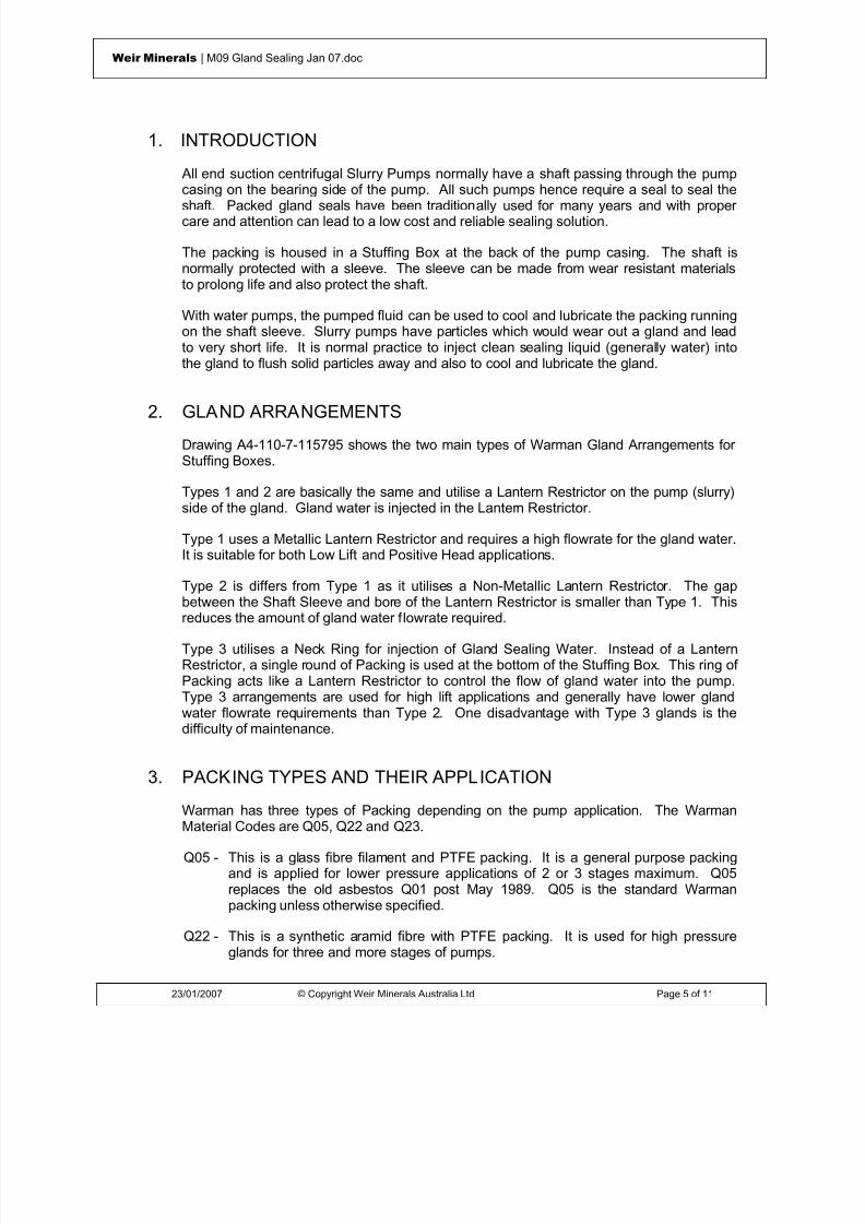
8/15/2019 r1_OF 71289_6 FF-AHF
http://slidepdf.com/reader/full/r1of-712896-ff-ahf 114/333
23/01/2007 © Copyright Weir Minerals Australia Ltd Page 5 of 11
Weir Minerals | M09 Gland Sealing Jan 07.doc
1. INTRODUCTION
All end suction centrifugal Slurry Pumps normally have a shaft passing through the pumpcasing on the bearing side of the pump. All such pumps hence require a seal to seal theshaft. Packed gland seals have been traditionally used for many years and with propercare and attention can lead to a low cost and reliable sealing solution.
The packing is housed in a Stuffing Box at the back of the pump casing. The shaft isnormally protected with a sleeve. The sleeve can be made from wear resistant materialsto prolong life and also protect the shaft.
With water pumps, the pumped fluid can be used to cool and lubricate the packing runningon the shaft sleeve. Slurry pumps have particles which would wear out a gland and leadto very short life. It is normal practice to inject clean sealing liquid (generally water) intothe gland to flush solid particles away and also to cool and lubricate the gland.
2. GLAND ARRANGEMENTS
Drawing A4-110-7-115795 shows the two main types of Warman Gland Arrangements forStuffing Boxes.
Types 1 and 2 are basically the same and utilise a Lantern Restrictor on the pump (slurry)side of the gland. Gland water is injected in the Lantern Restrictor.
Type 1 uses a Metallic Lantern Restrictor and requires a high flowrate for the gland water.It is suitable for both Low Lift and Positive Head applications.
Type 2 is differs from Type 1 as it utilises a Non-Metallic Lantern Restrictor. The gapbetween the Shaft Sleeve and bore of the Lantern Restrictor is smaller than Type 1. Thisreduces the amount of gland water flowrate required.
Type 3 utilises a Neck Ring for injection of Gland Sealing Water. Instead of a LanternRestrictor, a single round of Packing is used at the bottom of the Stuffing Box. This ring ofPacking acts like a Lantern Restrictor to control the flow of gland water into the pump.Type 3 arrangements are used for high lift applications and generally have lower glandwater flowrate requirements than Type 2. One disadvantage with Type 3 glands is thedifficulty of maintenance.
3. PACKING TYPES AND THEIR APPLICATION
Warman has three types of Packing depending on the pump application. The WarmanMaterial Codes are Q05, Q22 and Q23.
Q05 - This is a glass fibre filament and PTFE packing. It is a general purpose packingand is applied for lower pressure applications of 2 or 3 stages maximum. Q05replaces the old asbestos Q01 post May 1989. Q05 is the standard Warmanpacking unless otherwise specified.
Q22 - This is a synthetic aramid fibre with PTFE packing. It is used for high pressureglands for three and more stages of pumps.

8/15/2019 r1_OF 71289_6 FF-AHF
http://slidepdf.com/reader/full/r1of-712896-ff-ahf 115/333
23/01/2007 © Copyright Weir Minerals Australia Ltd Page 6 of 11
Weir Minerals | M09 Gland Sealing Jan 07.doc
Q23 - This is a synthetic aramid fibre with PTFE packing. It is formulated to resistextrusion due to higher than normal gland water pressures and is the standardpacking for the Warman Uniform Compression (type UC) gland.
All three packing are used with Tungsten Carbide coated shaft sleeves - Warman materialcode J21. All three packing types have scarf joints.
For multistage applications, packing Q22 has been proven to give long life. To reduce theextrusion of packing from the gland a packing retainer is normally used at the gland end ofthe stuffing box.
Fitment of Packing in a Stuffing Box
The packing should be placed around the shaft sleeve and the scarf ends should bebrought together. The joint should then be pushed into the annulus between the stuffingbox and shaft sleeve. The rest of the packing should then be pushed into the annulus bystarting near the joint and working around to the opposite side of the ring. Once thepacking ring is started, push evenly all the way around the packing and gently push to the
bottom keeping the packing as a ring.
4. GLAND SEALING WATER FLOW AND PRESSUREREQUIREMENTS
Gland water must be supplied at the correct pressure and flow to achieve a long packingand sleeve life. Correct pressure is the most critical requirement to achievingsatisfactory gland life. Flowrate is the next most important requirement . Flowrate isgoverned to some extent by the gland dimensions and also is adjustable within limits bymeans of the gland adjustment using the gland nuts.
The gland water supply pressure must be controlled to acceptable limits. For normalgland operation, the gland water pressure should be set at +35 to +70 kPa above thepump discharge pressure. This ensures that water will enter the gland with sufficientpressure to flush solids away. If too low, the pump pressure can force slurry into thegland and even up the gland and even up the gland water pipe to the gland water pumps.This is too be avoid at all cost.
Gland pressure that is too high will cause extrusion of the packing at the gland and pumpends of the stuffing box. Extrusion of packing causes both a degradation of the packingand less flowrate from the gland overtime. Both these things lead to packing failure. Upto +200 kPa above the pump discharge pressure should not cause too much degradationalthough the packing life is likely to be greatly reduced and high pressures are to beavoided .
The recommended, minimum total gland sealing water (GSW) flowrates for standardapplications are:

8/15/2019 r1_OF 71289_6 FF-AHF
http://slidepdf.com/reader/full/r1of-712896-ff-ahf 116/333
23/01/2007 © Copyright Weir Minerals Australia Ltd Page 7 of 11
Weir Minerals | M09 Gland Sealing Jan 07.doc
MINIMUM TOTAL GSW FLOWRATES(L/min)
Frame Size TYPE 1Metal Lantern
Restrictor
TYPE 2Non-MetallicRyton (P50)
LanternRestrictor
TYPE 3*Lantern Ringand Neck Ring
A 9 4 0.8
B, N, NP 15 6 1.0
C, P 21 7 1.5
D, Q 33 9 2
E, R 42 12 4
F, SHH 60 16 6
FAM, G, ST, S, T 100 26 9
GAM, H, TU 120 34 11
U 185 - 17
* Lantern ring is either metal (C23), Ryton (P50) or PTFE (P05)
Notes:
• The metal lantern restrictor may be used when a larger GSW flowrate can betolerated and where the type of pump duty requires high GSW flowrate e.g. milldischarge.
• With the aging and deterioration of a pump gland the required GSW Flowrate canbe up to three times (3x) higher than listed above. Any design of a GSW supplysystem should take this higher flowrate into account.
Gland Sealing Water Controls
There are a number of different gland water control devices that can be used viz.• Visual Flow Indicator• Throttle Valve• Constant Flow Orifice Valve• Combined Rotatmeter and• Flowrate regulator or selected length of capillary throttling tube.
The most common type is a Constant Flow Orifice Valve. This type of valve is essentiallya synthetic rubber O-ring housed in a socket. The O-ring shrinks in diameter as the

8/15/2019 r1_OF 71289_6 FF-AHF
http://slidepdf.com/reader/full/r1of-712896-ff-ahf 117/333
23/01/2007 © Copyright Weir Minerals Australia Ltd Page 8 of 11
Weir Minerals | M09 Gland Sealing Jan 07.doc
supply pressure increases. This maintains a reasonably constant flowrate into a glandirrespective of the gland sealing water pressure.
The Constant Flow Orifice is generally useful when there is considerable fluctuation in thegland water pressure. It can also assist when a group of pumps is fed by one glandsupply line and one or more pumps are not operating or they have worn glands. In thisinstance, it can prevent starvation of gland water on the pumps which are operating.
Troubleshooting
Most gland problems can be traced to two reasons:
(a) Inadequate or Excessive Gland Water Pressure
Inadequate pressure results in contamination of the packing by the pumped slurry.Once solids are embedded in the packing, they cannot be flushed out and thepacking must be replaced. Seal water pressure should be 35-70 kPa above thepump discharge pressure. Pressure in excess of this only results in more wear on
the packing and shaft sleeve.(b) Inadequate Flow
Like inadequate pressure, this results in contamination of the packing by thepumped slurry. Often this problem occurs with a seal water system which suppliesseveral pumps, without flow control to each pump. In this case, the low pressurepump takes all the available seal water and starves the higher pressure pump.Flow to each gland should be controll ed .
To achieve the above limits, it may be necessary to filter the water to at least reduce anysolids content to the lowest practical.
The gland sealing water supply must be reliable, as slurry pumps must not beoperated without gland water supply , otherwise major gland problems will beexperienced due to the high pressure forcing slurry into the gland region and causingwear and leakage.

8/15/2019 r1_OF 71289_6 FF-AHF
http://slidepdf.com/reader/full/r1of-712896-ff-ahf 118/333
23/01/2007 © Copyright Weir Minerals Australia Ltd Page 9 of 11
Weir Minerals | M09 Gland Sealing Jan 07.doc
PROBLEM CAUSE SOLUTION
Short Packing Life
Short Sleeve life
Slurry exists gland
• Slurry wears packing
• Slurry wears shaftsleeve
• Packing over heatingand burning due tolow GSW flow
• Increase GSWpressure
• Increase GSWflow
• Loosen gland toincrease flow
• Stop, cool down,repack and thanrestart with correctGSW pressureand flow
Flow from gland too low inworst case steam exitsfrom gland
• Pressure too highcausing packingextrusion and flowrestriction
• Gland too tight
• Packing too soft forhigh pressure
• Stop, cool down,repack and thanrestart with correctGSW pressureand flow
• Loosen gland
• Review packingtype
• Use packingretainer ring
• Reduce GSWpressure
GSW flows around outsideof packing rings
• Packing rings wrongsize or fit-up wrong
• Repack gland withcorrect packing
• Review order ofassembly
Too much flow from gland • Shaft sleeve worn
• Wrong size packing
• Worn packing
• Disassemble andrefurbish glandwith new parts
CAUTION

8/15/2019 r1_OF 71289_6 FF-AHF
http://slidepdf.com/reader/full/r1of-712896-ff-ahf 119/333

8/15/2019 r1_OF 71289_6 FF-AHF
http://slidepdf.com/reader/full/r1of-712896-ff-ahf 120/333
23/01/2007 © Copyright Weir Minerals Australia Ltd Page 11 of 11
Weir Minerals | M09 Gland Sealing Jan 07.doc

8/15/2019 r1_OF 71289_6 FF-AHF
http://slidepdf.com/reader/full/r1of-712896-ff-ahf 121/333
© Weir Minerals Australia Ltd 2007. Weir Minerals Australia Ltd. is the owner of the Copyright in this document. The document and its text, images, diagrams, data andinformation it contains must not be copied or reproduced in whole or in part, in any form or by any means, without the prior written consent of Weir Minerals Australia Ltd.
Office of origin : Pump Technology Centre, Artarmon Reference : Pump Manuals
Date : 9 February 2007 Last Issued: July 2005
Assembly & MaintenanceInstructionsSupplement ‘P50’
Horizontal Froth Pumps Types (AHF, MF & LF)

8/15/2019 r1_OF 71289_6 FF-AHF
http://slidepdf.com/reader/full/r1of-712896-ff-ahf 122/333
09/02/2007 © Copyright Weir Minerals Australia Ltd Page 2 of 10
Weir Minerals | P50 Horizontal Froth Pumps (AHF, MF & LF) Feb 07.doc
WarningsPersonnel injury and / or equipment damage could result from not observing the followingIMPORTANT SAFETY INFORMATION
. • A pump is both a pressure vessel and a piece of rotating equipment . All standard safetyprecautions for such equipment should be followed before and during installation, operation andmaintenance.
• For auxiliary equipment (motors, belt drives, couplings, gear reducers, variable speed drives,mechanical seals, etc) all related safety precautions should be followed and appropriateinstruction manuals consulted before and during installation, operation, adjustment andmaintenance.
• All guards for rotating equipment must be correctly fitted before operating the pump includingguards temporarily removed for gland inspection and adjustment. Seal guards should not be
removed or opened while the pump is running. Personal injury may result from contact withrotating parts, seal leakage or spray.•
Driver rotation must be checked before belts or couplings are connected.•
Pumps must not be operated at low or zero flow conditions for prolonged periods, or underany circumstances that could cause the pumping liquid to vaporise. Personnel injury andequipment damage could result from the high temperature and pressure created.
• Pumps must be used only within their allowable limits of pressure, temperature and speed.These limits are dependent on the pump type, configuration and materials used.
• Do not apply heat to t he impeller boss or nose in an effort to loosen the impeller thread priorto impeller removal. Personnel injury and equipment damage could result from the impellershattering or exploding when the heat is applied.
• Do not feed very hot or very cold liquid into a pump which is at ambient temperature.Thermal shock may cause the pump casing to crack.
• LIFTING of components
• Tapped holes (for eye bolts) and lugs (for lifting shackles) on Warman pumps are forlifting Individual parts only .
• Lifting devices of adequate capacity must be used wherever they are required to beused.
• Safe workshop practices should be applied during all assembly and maintenance work.
• Personnel must never work under suspended loads.• The pump must be fully isolated before any maintenance work, inspection or troubleshootinginvolving work on sections which are potentially pressurised (eg casing, gland, connectedpipework) or involving work on the mechanical drive system (eg shaft, bearing assembly,coupling). Power to the electric motor must be isolated and tagged out. It must be proven thatthe intake and discharge openings are totally isolated from all potentially pressurisedconnections and that they are and can only be exposed to atmospheric pressure.
•

8/15/2019 r1_OF 71289_6 FF-AHF
http://slidepdf.com/reader/full/r1of-712896-ff-ahf 123/333
09/02/2007 © Copyright Weir Minerals Australia Ltd Page 3 of 10
Weir Minerals | P50 Horizontal Froth Pumps (AHF, MF & LF) Feb 07.doc
Castings made from materials listed are brittle and have low thermal shock resistance. Attempts to repair or rebuild by welding may cause catastrophic failure. Repairs of suchcastings using these methods must not be attempted - A03, A04, A05, A06, A07, A08, A09,
A12, A14, A49, A51, A52, A53, A61, A210, A211, A217, A218, A509.•
Impellers must be tight on the shaft before any start-up, ie all components on the shaft betweenthe impeller and the pump end bearing must butt metal to metal against each other without anygap. Note that gaps may form when the pump experiences duty conditions conducive tounscrewing of the impeller, such as excessive runback, high intake pressure, motor braking etc.
• Burning of elastomer pump components will cause emission of toxic fumes and result in airpollution which could lead to personnel injury.
• Leakage from the pump shaft seals and/or leakage from worn pump components or seals maycause water and/or soil contamination.
• Liquid waste disposal from servicing of pumps or stagnant water from pumps stored for longperiods, may cause water and/or soil contamination.
• Do not apply anti-seize compounds to the impeller or shaft threads or to elastomer sealsduring assembly. Anti-seize can greatly reduce the impeller thread friction and may cause theimpeller to loosen during pump shut-down and run-back resulting in pump damage, or theelastomer seals to leak at reduced pressure.
• This manual applies only to genuine Warman parts and Warman recommended parts.
• Mixing of new and worn pump parts may increase the incidence of premature pump wear andleakage.
• Large foreign objects or tramp entering a pump will increase the incidence of higher wear and/ or damage to the pump. Routine inspection and maintenance of mill trommel screens willassist to reduce the danger of grinding balls entering a mill discharge pump.
• Large variations in slurry properties may lead to accelerated rates of wear and corrosion ofpump components eg• Wear increases exponentially with velocity and slurry particle size.• Corrosion rate doubles for every 10 degree Celsius increase in slurry temperature.• Corrosion rate increases exponentially as slurry pH decreases.
8/15/2019 r1_OF 71289_6 FF-AHF
http://slidepdf.com/reader/full/r1of-712896-ff-ahf 124/333
09/02/2007 © Copyright Weir Minerals Australia Ltd Page 4 of 10
Weir Minerals | P50 Horizontal Froth Pumps (AHF, MF & LF) Feb 07.doc
ISSUED: FEBRUARY 2007 LA ST ISSUE: JULY 2005
WARMAN PUMPS ASSEMBLY AND MAINTENANCE INSTRUCTIONS
SUPPLEMENT ‘P50’HORIZONTAL FROTH PUMPS
AHF, MF & LF
CONTENTS
WARNINGS 2
CONTENTS 4
1 INTRODUCTION 5
Subject of this Manual 5
Related documents 5
2 ASSEMBLY INSTRUCTIONS 5
General 5
Wet End Assembly 6
General 6
Fitting Impeller 6
Fitting Cover Plate 6
3 APPENDIX 7
Glossary of Terms 7
BASIC NUMBERS AND PARTS LIST 10

8/15/2019 r1_OF 71289_6 FF-AHF
http://slidepdf.com/reader/full/r1of-712896-ff-ahf 125/333
09/02/2007 © Copyright Weir Minerals Australia Ltd Page 5 of 10
Weir Minerals | P50 Horizontal Froth Pumps (AHF, MF & LF) Feb 07.doc
1 INTRODUCTION
Subject of th is Manual
Subject of this manual are Warman Horizontal Froth pumps identified by the letter F in the
pump type designation. These pumps are basically a standard Warman pump but includea modified wet end to accommodate for the specific needs of froth pumping. Viscous andnon-Newtonian slurries may also be processed. The range of pumps are:-
AHF - derived from AH pumpMF - derived from M pumpLF - derived from L pump
This manual only describes the ‘modified’ wet end of the pump. The other parts of thepump are identical with the basic pump and are covered by the manual for the basicpump.
Related documents
M1 General instructions applicable to all Warman PumpsP3 AH & M Pumps
P2 L Pumpsdepending onpump type
BA2 Basic Bearing Assemblies
BA3 Modified Basic Bearing Assemblies
M2 Impeller Release Collar
M8 Type ‘HS’ Centrifugal Seals
M9 Gland Seals
depending on
pump
configuration
Table 1 List of related manuals
This manual has to be read in conjunction with the Components Diagram for the particularpump.
2 ASSEMBLY INSTRUCTIONS
General
When pumps have been dismantled for complete overhaul, all parts should be closelyinspected and new parts checked for correct identification.
Used parts being replaced should be thoroughly cleaned and repainted where required.Mating faces and spigots should be free of rust, dirt and burrs and given a coat of greasebefore they are fitted together to assist future overhaul.
It is preferable to renew small bolts and set screws during overhaul and all threadsshould be coated with graphite grease before assembly. It is also recommended that all

8/15/2019 r1_OF 71289_6 FF-AHF
http://slidepdf.com/reader/full/r1of-712896-ff-ahf 126/333
09/02/2007 © Copyright Weir Minerals Australia Ltd Page 6 of 10
Weir Minerals | P50 Horizontal Froth Pumps (AHF, MF & LF) Feb 07.doc
rubber seals should be replaced during major overhauls as rubber tends to harden andseals lose their effectiveness.
Wet End Assembly
General
Horizontal Froth pumps use ‘HS1’ components for the wet end of i.e. HS1 Stuffing Box,HS1 Expeller Ring, HS1 Back Liner.
This manual assumes that the pump is built up to and including COVER PLATE BOLTS(015) inserted in FRAME PLATE (036HS1).
Fitting Impeller
1. Apply grease to shaft thread.
2. Make sure that the various O-Rings on the Shaft are not damaged during assemblyand that they are fully covered by the various parts.
3. Lift Impeller with the IMPELLER LIFTING TOOL (313) and turn Shaft by means ofthe Shaft Clamp to screw on Impeller. Tighten Impeller with bar between vanes andflogging Shaft Wrench. Confirm the gap between the Shaft Sleeve and theLabyrinth has now vanished.
During above action, the back of the Impeller may come in contact with theFrame plate liner insert. This is of no concern as long as the Bearing
Assembly is free and able to slide.
4. By means of one Nut on the ADJUSTING SCREW (001) move the Bearing Assembly backwards to a position just clear of the Frame Plate Liner Insert.Confirm Shaft and Impeller are turning freely.
Fitting Cover Plate
1. Fit THROATBUSH STUDS into THROATBUSH (083)
2. Rubber Lined Pump
Place COVER PLATE (013) on the ground with the intake flange down. PlaceVOLUTE LINER (018) into cover plate. Place Throatbush into position and applysoap to the lip area. By means of a tyre lever work the Throatbush down until itcontacts the lip of the molded on seal. Place the nuts of the Throatbush Studs and
tighten moderately.
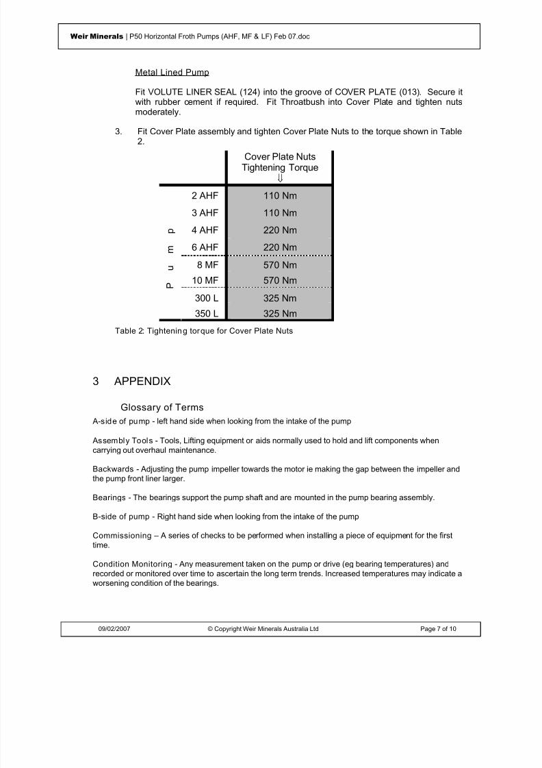
8/15/2019 r1_OF 71289_6 FF-AHF
http://slidepdf.com/reader/full/r1of-712896-ff-ahf 127/333
09/02/2007 © Copyright Weir Minerals Australia Ltd Page 7 of 10
Weir Minerals | P50 Horizontal Froth Pumps (AHF, MF & LF) Feb 07.doc
Metal Lined Pump
Fit VOLUTE LINER SEAL (124) into the groove of COVER PLATE (013). Secure itwith rubber cement if required. Fit Throatbush into Cover Plate and tighten nutsmoderately.
3. Fit Cover Plate assembly and tighten Cover Plate Nuts to the torque shown in Table2.
Cover Plate NutsTightening Torque
⇓
2 AHF 110 Nm
3 AHF 110 Nm
4 AHF 220 Nm
6 AHF 220 Nm
8 MF 570 Nm
10 MF 570 Nm
300 L 325 Nm
P
u
m
p
350 L 325 Nm
Table 2: Tightenin g torque for Cover Plate Nuts
3 APPENDIX
Glossary of Terms A-side of pump - left hand side when looking from the intake of the pump
Assembly Tools - Tools, Lifting equipment or aids normally used to hold and lift components whencarrying out overhaul maintenance.
Backwards - Adjusting the pump impeller towards the motor ie making the gap between the impeller andthe pump front liner larger.
Bearings - The bearings support the pump shaft and are mounted in the pump bearing assembly.
B-side of pump - Right hand side when looking from the intake of the pump
Commissioning – A series of checks to be performed when installing a piece of equipment for the firsttime.
Condition Monitoring - Any measurement taken on the pump or drive (eg bearing temperatures) andrecorded or monitored over time to ascertain the long term trends. Increased temperatures may indicate aworsening condition of the bearings.

8/15/2019 r1_OF 71289_6 FF-AHF
http://slidepdf.com/reader/full/r1of-712896-ff-ahf 128/333

8/15/2019 r1_OF 71289_6 FF-AHF
http://slidepdf.com/reader/full/r1of-712896-ff-ahf 129/333
09/02/2007 © Copyright Weir Minerals Australia Ltd Page 9 of 10
Weir Minerals | P50 Horizontal Froth Pumps (AHF, MF & LF) Feb 07.doc
Maintenance - Any activity that is carried out to prolong the pumps life or to refurbish it to new condition.
Overhaul Maintenance - Replacing parts (worn for new) to bring the performance back to new condition.This activity can be carried out In-Situ or in a workshop and involves disassembly, replacement of worn orfailed components and then re-assembly with new components.
Preventative Maintenance - Any activity that prevents failure or prolongs the life of the components.Some of these activities will involve overhauling and some will be carried out while the pump is running.
Assessments of maintenance needs will often be based on the results of Condition Monitoring.
Running (or routine) Maintenance - Normally is carried out with the pump running or during standbywithout any dismantling required - eg check and topping up oil level; checking bearing temperatures andvibrations or checking for leaks or operating faults.
Newtonian Fluid - A fluid having a constant viscosity for all shear rates. Most low concentration slurriesand many viscous liquids are newtonian.
Non-Newton ian Fluid - A fluid where the viscosity is not constant for all shear rates. High solidsconcentration, fine particles slurries are often non-newtonian.
Shut-down - The pump is turned off and isolated from the electrical supply and pipework. Certainprocedures need to be followed before switching off the pump (or shutting down or turning off).
Slurry Pump - A centrifugal pump for pumping slurries (water and solid particles). The pump is normallyof robust construction with replace internal liners and impellers made from abrasive resistant materials toprolong its life.
Start-up - The pump is switched on. Certain procedures need to be followed before switching on thepump (and during the initial stages of pumping).
Spare Parts - Components such as hard metal liners and impellers that are replaced to maintain thepumps performance. Spare parts can also include bearings, bolts and consumable items such as oil.
Tapered Roller Bearing - A type of bearing manufactured by the Timken Company that has rollersarranged so that they roller on a taper. Good at absorbing both radial and thrust loads. This style ofbearing is utilised on the Warman Bearing assembly on the pump (or wet) end to take both the pump.
Throatbush - The name of the liner used at the front of the pump against which the impeller rotates.
Tightening Down - A general term for tightening bolts (sometimes in sequence) to their requiredtightness or torque.
Warman Basi c Part Number - A three digit number incorporated in all Warman part numbers whichcharacterises the particular part eg all Warman shafts have a basic part number of "073".
Wet End - The actual pump including casing, impeller and liners which is mounted on the base andbearings (or frame).

8/15/2019 r1_OF 71289_6 FF-AHF
http://slidepdf.com/reader/full/r1of-712896-ff-ahf 130/333
09/02/2007 © Copyright Weir Minerals Australia Ltd Page 10 of 10
Weir Minerals | P50 Horizontal Froth Pumps (AHF, MF & LF) Feb 07.doc
BASIC NUMBERS AND PARTS LIST
A
ADJUSTING SCREW (001) 6
C
COVER PLATE (013) 6, 7
COVER PLATE BOLTS (015) 6
F
FRAME PLATE (036HS1) 6
I
IMPELLER LIFTING TOOL (313) 6
T
THROATBUSH (083) 6
THROATBUSH STUDS 6
V
VOLUTE LINER (018) 6
VOLUTE LINER SEAL (124) 7

8/15/2019 r1_OF 71289_6 FF-AHF
http://slidepdf.com/reader/full/r1of-712896-ff-ahf 131/333

8/15/2019 r1_OF 71289_6 FF-AHF
http://slidepdf.com/reader/full/r1of-712896-ff-ahf 132/333
Weir Minerals Latin AmericaVulco Perú S.A.
ExcellentMineralsSolutions
Manual de Operaciones y Mantenimiento
MotorMotor
Av. Separadora Industrial 2201Ate – Lima, Perú
T: +51 (1) 6187575E: [email protected]
W: www.weirminerals.com

8/15/2019 r1_OF 71289_6 FF-AHF
http://slidepdf.com/reader/full/r1of-712896-ff-ahf 133/333
Installation and Maintenance Manualfor Electric Motors
Manual de Instalación y Mantenimientode Motores Eléctricos
Aufstellungs - Und Wartungsanleitungenfür Elektrische Motoren
Stator/ Estator/ Ständer
Terminal Box/ Caja de ConexiónKlemmenkasten
Non-Drive Endshield/ Tapa Trasera/ BS-Lagerschild
Fan/ Ventilador/ Lüfter
Fan Cover/ Tapa Deflectora/ Lüfterhaube

8/15/2019 r1_OF 71289_6 FF-AHF
http://slidepdf.com/reader/full/r1of-712896-ff-ahf 134/333
The electric motor is an equipment widely used by man inthe industrial development as most of the machines he hasbeen inventing depend on it.
Taking into consideration the prominent role the electricmotor plays on people’s life, it must be regarded as a primepower unit embodying features that require special careincluding its installation and maintenance in order to ensureperfect operation and longer life to the unit. This means thatthe electric motor should receive particular attention.
The INSTALLATION AND MAINTENANCE MANUAL FORLOW VOLTAGE THREE-PHASE INDUCTION MOTORS intendsto assist those who deal with electric machines facilitatingtheir task to preserve the most important item of the unit:
THE ELECTRIC MOTOR.
WE G WE G WE G WE G WE G
FOREWORDFOREWORDFOREWORDFOREWORDFOREWORD
Installation and Maintenance Manual for Electric Motors

8/15/2019 r1_OF 71289_6 FF-AHF
http://slidepdf.com/reader/full/r1of-712896-ff-ahf 135/333
1 - INTRODUCTION ............................................................................................................................................1-032 - BASIC INSTRUCTIONS ..................................................................................................................................1-032.1 - General Instructions .............................................................................. ......................................... ..............1-032.2 - Delivery ....................................................................................................................... .................................1-032.3 - Storage ..................................................... .......................................................... .........................................1-03
3 - INSTALLATION ..............................................................................................................................................1-043.1 - Mechanical Aspects .....................................................................................................................................1-043.1.1 - Foundation................................................................................................................................................1-043.1.2 - Types of bases ............................................... ............................................... .......................................... ..1-043.1.3 - Alignment .......................................... ............................................... .................................... ...................1-043.1.4 - Coupling ...................................................................................................................................................1-053.2 - Electrical Aspects .........................................................................................................................................................1-093.2.1 - Power Supply System............................................................................ ............................................ .......1-093.2.2 - Starting of Electric Motors .................................................. ............................................. ........................1-093.2.3 - Motor Protection ................................................ ..................................................... .................................1-10
3.3 - Start-up ......................................................................................................................................1-113.3.1 - Preliminary Inspection ................................................ ............................................... .............................1-113.3.2 - The First Start-up ............................................. ................................................ ........................................1-113.3.3 - Operation ...................................................................................................................... ............................1-123.3.4 - Stopping ...................................................................................................................................................1-12
4 - MAINTENANCE............................................................................................................................................1-144.1 - Cleanliness ......................................................................................................................................................1-144.2 - Lubrication ..................................................................................................................................................1-144.2.1 - Lubrication Intervals ................................................................................................................................1-144.2.2 - Quality and Quantity of Grease ................................................................................................................1-144.2.3 - Lubrication Instructions ...........................................................................................................................1-144.2.4 - Replacement of Bearings .........................................................................................................................1-144.3 - Miscellaneous Recommendations ..........................................................................................................................1-15
5 - ABNORMAL SITUATIONS DURING OPERATION.........................................................................................1-19
TABLE OF CONTENTS
Installation and Maintenance Manual for Electric Motors

8/15/2019 r1_OF 71289_6 FF-AHF
http://slidepdf.com/reader/full/r1of-712896-ff-ahf 136/333
1 - INTRODUCTION
This manual covers all WEG asynchronous induction squirrel cagemotors, that is, three phase motors in frames 63 to 355, and single-phase motors.
The motors mentioned in this manual are subject to continuousimprovement. Therefore, any information is subject to change
without prior notice.For further details, please contact WEG.
2 - BASIC INSTRUCTIONS
2.1 - GENERAL INSTRUCTIONS
All personnel involved with electrical equipment, either installation,operation or maintenance should be well-informed and updatedconcerning the safety norms and principles that govern the workand, furthermore, they are advised to heed them. Before workcommences, it is the responsibility of the person in charge to ascertainthat these have been duly complied with and to alert his personnelof the inherent hazards of the job in hand.It is recommended that these tasks be undertaken by qualified
personnel.Fire fighting equipment, and notices concerning first aid should notbe lacking at the work site; these should be visible and accessible atall times.
2.2 - DELIVERY
Prior to shipment, motors are factory-tested and dynamically balanced. With half key to ensure perfect operation.Upon receipt, we recommend careful handling and a physicalchecking for any damage which may have occured duringtransportation.In the event of any damage, both the nearest WEG sales office andthe carrier should be informed immediately.
2.3 - STORAGEMotors should be lifted by their eyebolts and never by the shaft.Raising and lowering must be steady and joltless, otherwise bearingsmay be damaged.When motors are not immediately installed, they should be storedin their normal upright position in a dry even temperature place,free of dust, gases and corrosive smoke. Other objects should not beplaced on or against them.Motors stored over long periods are subject to loss of insulationresistance and oxidation of bearings.
Bearings and the lubricant deserve special attention during longperiods of storage. Depending on the length and conditions of storage it may be necessary to regrease or change rusted bearings.
The weight of the rotor in an inactive motor tends to expel greasefrom the bearing surfaces thereby removing the protective film thatimpedes metal-to-metal contact. As a preventive measure againstthe formation of corrosion by contact, motors should not be storednear machines which cause vibrations, and their shaft should berotated manually at least once a month.
Recommendations for Storage of Bearings:
- Ambient must be dry with relative humidity not exceeding 60%.- Clean room with temperature ranging from 10ºC to 30ºC.- Maximum stacking of 5 boxes.- Far from chemical products and tubes conducting steams, water and compressed air.- They should not be stacked over stone floors or against walls.- Stock should follow the first-in-first-out principle.- Double shielded bearings should not remain in stock for more than 2 years.
Storage of motors:- Mounted motors which are kept in stock must have their shaftturned periodically, at least once a month, in order to renew thegrease on the bearing races.
It is difficult to prescribe rules for the actual insulation resistance value of a machine as the resistance varies according to the type,size and rated voltage and the state of the insulation material used,method of construction and the machine’s insulation antecedents.A lot of experience is necessary to decide when a machine is ready or not to be put into service. Periodical records are useful to takesuch decision.
The following guidelines show the approximate values that can beexpected of a clean and dry machine when, at 40ºC, test voltage isapplied over a period of one minute.
Insulation resistance Rm is obtained by the formula:
Rm = Un + 1
where: Rm - minimum recommended insulationresistance in M with winding at 40ºC.
Un - machine rated voltage in kV.
In case that the test is carried out at a temperature other that 40ºC,the reading must be corrected to 40ºC using a curve of insulationresistance vs. temperature for the particular machine. If such curveis not available, an approximation is possible with the aid of Figure2.1; it is possible to verify that resistance practically doubles every
10ºC that insulating temperature is lowered.
On new machines, lower values are often attained due to solventspresent in the insulating varnishes that later evaporate during normaloperation. This does not necessarily mean that the machine is notoperational, since insulating resistance will increase after a periodof service.
On motors which have been in service for a period of time, muchlarger values are often attained. A comparison of the values recordedin previous tests on the same machine, under similar load,temperature and humidity conditions, serves as a better indicationof insulation condition than that of the value coming from a singletest. Any substantial or sudden reduction is suspect.
Insulation resistance is usually measured with a MEGGER. In theevent that insulation resistance be inferior to the values comingfrom the above formula, motors should be submitted to a dryingprocess.
This drying process should be carried out in a stove, where the rateof temperature rise should not exceed 5ºC per hour and thetemperature should not exceed 110ºC.
Winding temperature (°C)R = R x K 40C t t40C
Fig. 2.1 Approximate calculation curve of the insulation resistance.
I n s u
l a t i o n r e s
i s t a n c e c o r r e c
t i o n
f a c
t o r
k t 4 0
o C
1-03Installation and Maintenance Manual for Electric Motors
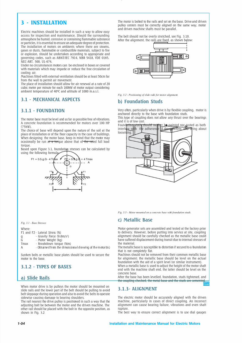
8/15/2019 r1_OF 71289_6 FF-AHF
http://slidepdf.com/reader/full/r1of-712896-ff-ahf 137/333
3 - INSTALLATION
Electric machines should be installed in such a way to allow easy access for inspection and maintenance. Should the surroundingatmosphere be humid, corrosive or containing flammable substanceor particles, it is essential to ensure an adequate degree of protection.
The installat ion of motors on ambients where there are steams,gases or dusts, flammable or combustible materials, subject to fireor explosion, should be undertaken according to appropriate andgoverning codes, such as ABNT/IEC 7914, NBR 5418, VDE 0165,NEC-ART. 500, UL-674.Under no circumstances motors can be enclosed in boxes or covered
with materials which may impede or reduce the free circulation of cooling air.Machines fitted with external ventilation should be at least 50cm farfrom the wall to permit air movement.
The place of installation should allow for air renewal at a rate of 20cubic meter per minute for each 100kW of motor output consideringambient temperature of 40ºC and altitude of 1000 m.a.s.l.
3.1 - MECHANICAL ASPECTS
3.1.1 - FOUNDATION
The motor base must be level and as far as possible free of vibrations.A concrete foundation is recommended for motors over 100 HP(75kW).
The choice of base will depend upon the nature of the soil at theplace of installation or of the floor capacity in the case of buildings.When designing the motor base, keep in mind that the motor may ocasionally be run at a torque above that of the rated full loadtorque.Based upon Figure 3.1, foundation stresses can be calculated by using the following formula:
F1 = 0.5.g.G - 4 Tmax A
F2 = 0.5.g.G + 4 Tmax A
Fig. 3.1 - Base Stresses
Where:F1 and F2 - Lateral Stress (N)g - Gravity Force (9.8m/s²)G - Motor Weight (kg)
Tmax - Breakdown torque (Nm)A - Obtained from the dimensional drawing of the motor(m)
Sunken bolts or metallic base plates should be used to secure themotor to the base.
3.1.2 - TYPES OF BASES
a) Slide Rails
When motor drive is by pulleys the motor should be mounted onslide rails and the lower part of the belt should be pulling to avoidbelt sleppage during operation and also to avoid the belts to operatesidewise causing damage to bearing shoulders.
The rail nearest the drive pulley is positioned in such a way that theadjusting bolt be between the motor and the driven machine. Theother rail should be placed with the bolt in the opposite position, asshown in Fig. 3.2.
The motor is bolted to the rails and set on the base. Drive and drivenpulley centers must be correctly aligned on the same way, motorand driven machine shafts must be parallel.
The belt should not be overly stretched, see Fig. 3.10.After the alignment, the rails are fixed, as shown below:
Fig. 3.2 - Positioning of slide rails for motor alignment.
b) Foundation Studs
Very often, particularly when drive is by flexible coupling, motor is
anchored directly to the base with foundation studs. This type of coupling does not allow any thrust over the bearingsand it is of low cost.Foundation studs should neither be painted nor rusted as bothinterfere with the adherence of the concrete, and bring aboutloosening.
Fig. 3.3 - Motor mounted on a concrete base with foundation studs.
c) Metallic Base
Motor-generator sets are assembled and tested at the factory priorto delivery. However, before putting into service at site, couplingalignment should be carefully checked as the metallic base couldhave suffered displacement during transit due to internal stresses of the material.
The metallic base is susceptible to distortion if secured to a foundationthat is not completely flat.Machines should not be removed from their common metallic basefor alignment; the metallic base should be level on the actualfoundation with the aid of a spirit level (or similar instrument).When a metallic base is used to adjust the height of the motor shaftend with the machine shaft end, the latter should be level on theconcrete base.After the base has been levelled, foundation, studs tightened, andthe coupling checked, the metal base and the studs are cemented.
3.1.3- ALIGNMENT
The electric motor should be accurately aligned with the drivenmachine, particularly in cases of direct coupling. An incorrectalignment can cause bearing failure, vibrations and even shaftrupture.
The best way to ensure correct alignment is to use dial gauges
1-04 Installation and Maintenance Manual for Electric Motors

8/15/2019 r1_OF 71289_6 FF-AHF
http://slidepdf.com/reader/full/r1of-712896-ff-ahf 138/333
placed on each coupling half, one reading radially and the otheraxially.
Thus, simultaneous readings are possible and allow checking forany parallel (Fig. 3.4) and concentricity deviations (Fig. 3.5) by rotating the shafts one turn.Gauge readings should not exceed 0.05 mm.
3.1.4- COUPLINGa) Direct Coupling
Direct coupling is always preferable due to low cost, space economy,no belt slippage and lower accident risk.In cases of speed ratio drives, it is also common to use a directcoupling with a reducer (gear box).CAUTION: Carefully align the shaft ends using, whenever feasible,a flexible coupling, leaving a minimum tolerance of 3 mm between
the couplings (GAP).
b) Gear Coupling
Poorly aligned gear couplings are the cause of jerking motions which cause vibrations on the actual drive and on the motor. Therefore, due care must be taken for perfect shaft alignment: exactly parallel in the case of straight gears and at the correct angle forbevel or helical gears.Perfect gear engagement can be checked by the insertion of a stripof paper on which the teeth marks will be traced after a singlerotation.
c) Belt and Pulley Coupling
Belt coupling is most commonly used when a speed ratio is required.Assembly of Pulleys : To assemble pulleys on shaft ends with akeyway and threaded end holes the pulley should be inserted halfway up the keyway merely by manual pressure.On shafts without threaded end holes, the heating of the pulley toabout 80ºC is recommended, or alternatively, the devices illustratedin Figure 3.6 may be employed.
Fig. 3.4 - Deviation from parallelism
Fig. 3.5 - Deviation from concentricity
Fig. 3.6 - Pulleymounting device
Hammers should be avoided during the fitting of pulleys andbearings. The fitting of bearings with the aid of hammers leavesblemishes on the bearing races. These initially small flaws increase
with usage and can develop to a stage that completely impairs thebearing.
The correct positioning of a pulley is shown in Figure 3.8.
W R O N G
W R O N G
R IG H T
R IG H T
RUNNING: To avoid needless radial stresses on the bearings it isimperative that shafts are parallel and the pulleys perfectly aligned.(Figure 3.9).
Fig. 3.8 - Correct positioning of pulley on the shaft.
R IG H T
W R O N G
W R O N G
Pulleys that are too small should be avoided; these cause shaftflexion because belt traction increases in proportion to a decrease
in the pulley size. Table 1 determines minimum pulley diameters,and Table 2 and 3 refer to the maximum stresses acceptable onmotor bearings up to frame 355.
Fig. 3.9 - Correct pulley alignment
TIG H T
1 0
t o 2
0 m
m
Laterally misaligned pulleys, when running, transmit alternatingknocks to the rotor and can damage the bearing housing. Beltslippage can be avoided by applying a resin (rosin for example).Belt tension should be sufficient to avoid slippage during operation.
Fig. 3.10 - Belt tensions Fig. 3.7 - Pulley extractor
1-05Installation and Maintenance Manual for Electric Motors

8/15/2019 r1_OF 71289_6 FF-AHF
http://slidepdf.com/reader/full/r1of-712896-ff-ahf 139/333
Frame PolesBearing
BALL BEARINGS
Size X ( mm )
TABLE 1.1
Frame Bearing
MINIMUM PITCH DIAMETER OF PULLEYS
BALL BEARINGS
Size X ( mm )
20 40 60 80 100 120
63 6201-ZZ 40 --- --- --- --- ---71 6203-ZZ 40 40 --- --- --- ---80 6204-ZZ 40 40 --- --- --- ---90 6205-ZZ 63 71 80 --- --- ---100 6206-ZZ 71 80 90 --- --- ---112 6307-ZZ 71 80 90 --- --- ---132 6308-ZZ --- 100 112 125 --- ---160 6309-Z-C3 --- 140 160 180 200 ---180 6311-Z-C3 --- --- 160 180 200 224200 6312-Z-C3 --- --- 200 224 250 280
50 80 110 140
225 IV-VI-VIII 6314 250 265 280 300250 IV-VI-VIII 6314 375 400 425 450280 IV-VI-VIII 6316 500 530 560 600315 IV-VI-VIII 6319 ----- ----- ----- -----355 IV-VI-VIII 6322 ----- ----- ----- -----
Size x (mm)
Roller Bearings
50 80 100 140 170 210
225 IV-VI-VIII NU 314 77 80 110 136 ----- -----250 IV-VI-VIII NU 314 105 115 145 175 ----- -----280 IV-VI-VIII NU 316 135 140 170 210 ----- -----315 IV-VI-VIII NU 319 ----- 170 185 225 285 -----355 IV-VI-VIII NU 322 ----- ----- 345 410 455 565
Frame PolesBearing
TABLE 1.2
1-06
For II pole motors, contact WEG.
Installation and Maintenance Manual for Electric Motors
TABLE 1
O
P I T C H

8/15/2019 r1_OF 71289_6 FF-AHF
http://slidepdf.com/reader/full/r1of-712896-ff-ahf 140/333
MAXIMUM ACCEPTABLE RADIAL LOAD (N) - IP55 MOTORS -60Hz
POLES
II IV VI VIII63 245 294 ----- -----71 294 392 ----- ----
80 343 491 ----- -----90 392 540 589 687100 589 785 883 981112 1040 1275 1472 1668132 1275 1570 1864 1962160 1570 1962 2256 2551180 2060 2649 3041 3434200 2354 3139 3630 4120225 3041 4120 4415 5003250 2845 3728 4316 4807280 3532 4513 5101 5690315 3335 4905 5690 6475355 ---- 15402 15402 15402
TABLE 2
F R A M E
MAXIMUM ACCEPTABLE RADIAL LOAD (Kgf) -60Hz AND 50Hz NEMA 56 MOTORS (SINGLE-PHASE)
RADIAL FORCE (N)
POLES
II IV VI VIII
56 A 245 343 ----- -----
56 B 294 343 ----- -----
56 D 343 441 ----- -----
SAW ARBOR MOTORS (THREE-PHASE)80 S - MS 981 ----- ----- -----
80 H - MS 981 ----- ----- -----
80 L - MS 981 ----- ----- -----
90 L - MS 1275 1570 ----- -----
FRAME
TABLE 2.1
MAXIMUM ACCEPTABLE RADIAL LOAD (N) - IP55 MOTORS -50Hz
POLES
II IV VI VIII63 245 294 ----- -----71 294 392 ----- ----80 343 491 ----- -----90 392 589 638 687100 589 834 932 1079
112 1079 1373 1570 1766132 1373 1668 1962 2060160 1668 2060 2403 2698180 2158 2796 3237 3630200 2502 3335 3826 4365225 3237 4365 4709 5297250 3041 3924 4611 5101280 3728 4807 5396 5984315 3532 5199 5984 6867355 ---- 16285 16285 16285
F R A M E
1-07Installation and Maintenance Manual for Electric Motors

8/15/2019 r1_OF 71289_6 FF-AHF
http://slidepdf.com/reader/full/r1of-712896-ff-ahf 141/333

8/15/2019 r1_OF 71289_6 FF-AHF
http://slidepdf.com/reader/full/r1of-712896-ff-ahf 142/333
3.2 - ELECTRICAL ASPECTS
3.2.1- POWER SUPPLY SYSTEM
Proper electric power supply is very important. The choice of motorfeed conductors, whether branch or distribution circuits, should bebased on the rated current of the motors as per IEC 34 Standard.
NOTE: In the case of variable speed motors, the highest value amongthe rated currents should be considered. When motor operation isintermittent the conductors should have a current carrying capacity equal or greater, to the product of the motor rated current times therunning cycle factor shown in Table 4.
IMPORTANT : For a correct choice of motor feed conductors, werecommend to check the standards requirements for industrialinstallations.
MAXIMUM ACCEPTABLE AXIAL LOAD (N) - f = 60 Hz and 50Hz
II IV II IV II IV II IV
56 A 294 392 363 491 275 373 343 471
56 B 294 392 353 481 275 363 343 461
56 D 275 383 461 638 255 353 441 608
FR AME
POSITION / MOUNTING CONFIGURATION FRAME
TABLE 3.1
In cases where motor starting current is high, this can causeinterference to the following:
a) Significant voltage drop in the power supply feeding system. Asa consequence, other equipment connected to the same system cansuffer interference.
b) The protection system (cables and contactors) must beoverdesigned leading to a high cost.
c) Power supply utilities will limit the supply voltage drop.
In cases where DOL starting is not feasible due to above givenreasons, then indirect system can be used in order to reduce thestarting current such as:
- Star-delta starting- Starting with compensating switch (auto-transformer starting)- Series-parallel starting- Electronic starting (soft-start)
STAR-DELTA STARTINGIt is fundamental for star-delta starting that three phase motor havethe required number of leads to allow connection on both voltages,that is, 220/380V, 380/660V or 440/760V.
These motors should have at least 6 connecting leads. The startinghas to be made at no load. The star-delta starting can be used whenthe motor torque curve is sufficiently high to guarantee accelerationof the load at reduced voltage. At star connection, current is reducedto 25% to 30% of the starting current in comparison to delta
connection. Torque curve is also reduced proportionally. For this reason, every time a star-delta starting is required, a high torque curve motormust be used.WEG motors have high starting and breakdown torque. Hence, they are suitable in most cases for star-delta starting.
The load resistant torque can not exceed the motor starting torque,neither the current when switching to delta connection can not be of an unacceptable value.
There are cases where this starting method can not be used. Forexample, when the resistant torque is too high. If the starting ismade at star, motor will accelerate the load up to approximately 85% of the rated speed. In this point, the switch must be connectedat delta. In this case, the current which is about the rated current
jumps, suddenly, which is in fact not advantageous, as the purposeis to reduce the starting current.
Table 5 shows the most common multiple rated voltages for threephase motors and their use to the usual power supply voltages.
The DOL or compensating switch starting is applicable to all casesof table 5.
1-09
TABLE 4
5 min.
1.10
0.85
0.85
1.10
15 min.
1.20
0.85
0.90
1.20
30 to 60min.
1.50
0.90
0.95
1.50
Continuous
-
1.40
1.40
2.00
Motor RatedService
Time
Service Duty Factor
Short (valveoperation, contactoperation, etc.)
Classification
Intermittent (load or
building elevators,tools, pumps, rollingbridges, etc.)
Periodical (Rolling mill,mining machines, etc.)
Variable
3.2.2 - STARTING OF ELECTRIC MOTORS
Induction motors can be started by the following methods:
DIRECT STARTINGWhenever possible a three phase motor with a squirrel cage shouldbe started directly at full voltage supply by means of contactors. Ithas to be taken into account that for a certain motor, torque andcurrent curves are fixed, independently of the load, for constant
voltage.
Installation and Maintenance Manual for Electric Motors
Fa1
Fa2
Fa1
Fa2
Fa1 Fa1
Fa2 Fa2

8/15/2019 r1_OF 71289_6 FF-AHF
http://slidepdf.com/reader/full/r1of-712896-ff-ahf 143/333

8/15/2019 r1_OF 71289_6 FF-AHF
http://slidepdf.com/reader/full/r1of-712896-ff-ahf 144/333
1-11
b) Manual overload protector when the resetting is done through amanual release.
Table 6 shows a comparison between motor protection systems.
TABLE 6
Current-basedprotectionCauses of
overheating
Fuse only
Protection withprobe
thermistor in motor
Fuse andthermal
protector
Overload with 1.2times rated current
COMPARISON BETWEEN MOTOR PROTECTION SYSTEMS
Duty cycles S1 toS10
Brakings, reversals
and frequent starts
Operation withmore than 15starts p/hour
Locked rotor
Fault on one phase
Excessive voltagefluctuation
Frequency
fluctuation onmain supply
Excessive ambienttemperature
External heatingcaused by bearings, belts,pulleys, etc.
Obstructed ventilation
CAPTION Unprotected Partially protected Totally protected
3.3 - START-UP
3.3.1 - PRELIMINARY INSPECTION
Before starting a motor for the first time, check the following:
a) Remove all locking devices and blocks used in transit and chekthat the motor rotates freely;b) Check if the motor is firmly secured and that coupling elements
are correctly mounted and aligned;c) Ascertain that voltage and frequency correspond to those indicatedon the nameplate. Motor performance will be satisfactory as longas voltage and frequency remain in the range determined by IECStandard.d) Check if connections are in accordance with the connectiondiagram shown on the nameplate and be sure that all terminalscrews and nuts are tight;
e) Check the motor for proper grounding. Providing that there areno specifications calling for ground-insulated installation, the motormust be grounded in accordance with prevalent standard forgrounding electrical machines. The screw identified by the symbol( ) should be used for this purpose. This screw is generally to befound in the terminal box or on the motor foot.f) Check if motor leads correspond with the main supply as well asthe control wires, and the overload protection device are inaccordance with IEC Standards;g) If the motor has been stored in a humid place, or has beenstopped for some time, measure the insulating resistance asrecommended under the item covering storage instructions;h) Start the motor uncoupled to ascertain that it is running freely and in the desired direction. To reverse the rotation of a three-phase motor, invert two terminalleads of the main power supply.Medium voltage motors having an arrow on the frame indicatingrotation direction can only turn in the direction shown;
3.3.2 - THE FIRST START-UP
THREE-PHASE MOTOR WITH SQUIRREL CAGE ROTOR
After careful checking of the motor, follow the normal sequence of starting operations listed in the control instructions for the initialstart-up.
63 6201-ZZ 6201-ZZ71 6203-ZZ 6202-ZZ80 6204-ZZ 6203-ZZ
90 S 6205-ZZ 6204-ZZ90 L 6205-ZZ 6204-ZZ100 L 6206-ZZ 6205-ZZ112 M 6307-ZZ 6206-ZZ132 S 6308-ZZ 6207-ZZ132 M 6308-ZZ 6207-ZZ160 M 6309-Z-C3 6209-Z-C3
160 L 6309-Z-C3 6209-Z-C3
180 M 6311-Z-C3 6211-Z-C3
180 L 6311-Z-C3 6211 -Z-C3
200 L 6312-Z-C3 6212-Z-C3
200 M 6312-Z-C3 6212-Z-C3
225 S/M 6314-C3 6314-C3
250 S/M 6314-C3 6314-C3
280 S/M 6314-C3** 6314-C3
6316-C3 6316-C3
315 S/M 6314-C3** 6314-C3
6319-C3 6316-C3
355 M/L 6314-C3 6314-C3
NU322-C3 6319-C3
BEARINGSMountingConfig.
FRAMES
TABLE 7
BEARING SPECIFICATIONBY MOTOR TYPE
TEFC motors
DE ODE
** Only valid for 2 pole motors.
a l l m o u n t i n g c o n
f i g u r a t i o n s
Installation and Maintenance Manual for Electric Motors

8/15/2019 r1_OF 71289_6 FF-AHF
http://slidepdf.com/reader/full/r1of-712896-ff-ahf 145/333
1-12
3.3.3 - OPERATION
Drive the motor coupled to the load for a period of at least one hour while watching for abnormal noises or signs of overheating.Compare the line current with the value shown on the nameplate.Under continuous running conditions without load fluctuations,this should not exceed the rated current times the service factor, alsoshown on the nameplate.All measuring and control instruments and apparatus should be
continuously checked for any deviation and any irregularitiescorrected.
3.3.4 - STOPPING
Warning:
To touch any mov ing part of a run ning motor, eve n thoughdisconnected, is a danger to life and limb.
Three-phase motor with squirrel cage rotor:Open the stator circuits switch. With the motor at a complete stop,reset the auto-transformer, if any, to the “start” position.
143 T 6205-ZZ 6204-ZZ
145 T 6205-ZZ 6204-ZZ182 T 6307-ZZ 6206-ZZ
184 T 6307-ZZ 6206-ZZ
213 T 6308-ZZ 6207-ZZ
215 T 6308-ZZ 6207-ZZ
254 T 6309-C3 6209-C3
256 T 6309-C3 6209-C3
284 T / TS 6311-C3 6211-C3
286 T / TS 6311-C3 6211-C3
324 T / TS 6312-C3 6212-C3
326 T / TS 6312-C3 6212-C3364 T / TS 6314-C3 6314-C3
365 T / TS 6314- C3 6314-C3
404 T 6314-C3 6314-C3
405 TS 6314-C3 6314-C3
444 T 6316-C3 6316-C3
444 TS 6314-C3** 6314-C3
445 T 6316-C3 6316-C3
445 TS 6314-C3** 6314-C3
504 Z 6319-C3 6316-C3
505 U 6314-C3** 6314-C3505 Z 6319-C3 6316-C3
586 T 6314-C3 6314-C3
587 T NU 322-C3 6319-C3
TABLE 8
BEARING SPECIFICATIONBY MOTOR TYPE
BEARINGSMountingConfig.
FRAMES
TEFC motors
DE ODE
** Only valid for 2 pole motors.
a l l m o u n t i n g c o n f i g u r a t i o n s
48B 6203-ZZ 6202-ZZ56 A 6203-ZZ 6202-ZZ56 B 6203-ZZ 6202-ZZ56 D 6204-ZZ 6202-ZZ56 H 6204-ZZ 6202-ZZ
BEARINGSMountingConfig.S A W
A R B O R DE O D E
TABLE 8A
80 S MS 6307-ZZ 6207-ZZ80 M MS 6307-ZZ 6207-ZZ80 L MS 6307-ZZ 6207-ZZ90 L MS 6308-ZZ 6208-ZZ
BEARING SPECIFICATIONBY MOTOR TYPE
BEARINGS FOR SAW ARBOR MOTORS
NEMA FRAME MOTORS TABLE 8B
ODP motors
BEARINGSMountingConfig. DE O D E
N E M AFrames
a l l m o u n t i n g
c o n
f i g u r a t i o n s
B 3
Installation and Maintenance Manual for Electric Motors

8/15/2019 r1_OF 71289_6 FF-AHF
http://slidepdf.com/reader/full/r1of-712896-ff-ahf 146/333
1-13
BALL BEARINGS - SERIES 62/63
Relubrication intervals (running hours - horizontal position)
II pole Amount of grease
Installation and Maintenance Manual for Electric Motors
Bearing
6209
6211
6212
Bearing
6309
6311
6312
6314
6316
6319
6322
IV pole VI pole VIII pole X pole XII pole
Serie 62
Serie 63
60Hz
18400
14200
12100
60Hz
15700
11500
9800
3600
-
-
-
50Hz
20000
16500
14400
50Hz
18100
13700
11900
4500
-
-
-
60Hz
20000
20000
20000
60Hz
20000
20000
20000
9700
8500
7000
5100
50Hz
20000
20000
20000
50Hz
20000
20000
20000
11600
10400
9000
7200
60Hz 50Hz 60Hz 50Hz 60Hz 50Hz 60Hz 50Hz (g)
20000 20000 20000 20000 20000 20000 20000 20000 9
20000 20000 20000 20000 20000 20000 20000 20000 11
20000 20000 20000 20000 20000 20000 20000 20000 13
60Hz 50Hz 60Hz 50Hz 60Hz 50Hz 60Hz 50Hz (g)
20000 20000 20000 20000 20000 20000 20000 20000 13
20000 20000 20000 20000 20000 20000 20000 20000 18
20000 20000 20000 20000 20000 20000 20000 20000 21
14200 16400 17300 19700 19700 20000 20000 20000 27
12800 14900 15900 18700 18700 20000 20000 20000 34
11000 13000 14000 17400 17400 18600 18600 20000 45
9200 10800 11800 15100 15100 15500 15500 19300 60
ROLLER BEARINGS - SERIES NU 3
Relubrication intervals (running hours - horizontal position)
II pole Amount of greaseIV pole VI pole VIII pole X pole XII pole
Bearing 60Hz 50Hz 60Hz 50Hz 60Hz 50Hz 60Hz 50Hz 60Hz 50Hz 60Hz 50Hz (g)
NU 309 9800 13300 20000 20000 20000 20000 20000 20000 20000 20000 20000 20000 13
NU 311 6400 9200 19100 20000 20000 20000 20000 20000 20000 20000 20000 20000 18
NU 312 5100 7600 17200 20000 20000 20000 20000 20000 20000 20000 20000 20000 21
NU 314 1600 2500 7100 8900 11000 13100 15100 16900 16900 19300 19300 20000 27
NU 316 - - 6000 7600 9500 11600 13800 15500 15500 17800 17800 20000 34
NU 319 - - 4700 6000 7600 9800 12200 13700 13700 15700 15700 20000 45
NU 322 - - 3300 4400 5900 7800 10700 11500 11500 13400 13400 17300 60
NU 324 - - 2400 3500 5000 6600 10000 10200 10200 12100 12100 15000 72
Notes:- The ZZ bearings from 6201 to 6307 do not require relubrication as its life time is about 20,000 hours.- Tables 9 and 10 are intended for the lubrication period under bearing temperature of 70°C (for bearings up to 6312 and NU 312) and temperature of 85°C (for bearings 6314 and NU 314 and larger).- For each 15°C of temperature rise, the relubrication period is reduced by half.- The relubrication periods given above are for those cases applying Polyrex ® EM grease.
Compatibility of Polyrex ® EM grease with other types of grease:
Containing polyurea thickener and mineral oil, the Polyrex ®
EM grease is compatible with other types of grease that contain:- Lithium base or complex of lithium or polyurea and highly refined mineral oil.- Inhibitor additive against corrosion, rust and anti-oxidant additive.
Notes:- Although Polyrex ® EM is compatible with types of grease given above, we do no recommended to mix it with any other greases.- If you intend to use a type of grease different than those recommended above , first contact WEG.- On applications (with high or low temperatures, speed variation, etc), the type of grease and relubrification interval are given on an dditional nameplate attached to the motor.
BEARING LUBRICATION INTERVALS AND AMOUNT OF GREASE TABLE 9
TABLE 10
When motors are used on the vertical position, their relubrication interval is reduced by half if compared to horizontal position motors.-

8/15/2019 r1_OF 71289_6 FF-AHF
http://slidepdf.com/reader/full/r1of-712896-ff-ahf 147/333
1-14 Installation and Maintenance Manual for Electric Motors
4 - MAINTENANCEA well-designed maintenance program for electric motors, whencorrectly used, can be summed up as: periodical inspection of insulation levels, temperature rise, wear, bearing lubrication at theoccasional checking of fan air flow.Inspection cycles depend upon the type of motor and the conditionsunder which it operates.
4.1 - CLEANLINESSMotors should be kept clean, free of dust, debris and oil. Soft brushesor clean cotton rags should be used for cleaning. A jet of compressedair should be used to remove non-abrasive dust from the fan coverand any accumulated grime from the fan and cooling fins.
Terminal boxes fitted to motors with IP-55 protection should becleaned; their terminals should be free of oxidation, in perfectmechanical condition, and all unused space dust-free.Motors with IP(W) 55 protection are recommended for use underunfavourable ambient conditions.
4.2 - LUBRICATION
Motors made up to frame 160 are not fitted with grease fitting, while larger frames up to frame 200 this device is optional.For frame 225 to 355 grease fitting is supplied as standard.Proper Lubrication extends bearing life.Lubrication Maintenance Includes:
a) Attention to the overall state of the bearings;b) Cleaning and lubrication;c) Careful inspection of the bearings.
Bearing temperature control is also part of routine maintenance. The temperature of bearings lubricated with suitable grease asrecommended under item 4.2.2 should not exceed 70°C.Constant temperature control is possible with the aid of externalthermometers or by embedded thermal elements. WEG motors arenormally equipped with grease lubricated ball or roller bearings.Bearings should be lubricated to avoid the metallic contact of themoving parts, and also for protection against corrosion and wear.Lubricant properties deteriorate in the course of time and mechanicaloperation and, furthermore, all lubricants are subject tocontamination under working conditions.For this reason, lubricants must be renewed and any lubricantconsumed needs replacing from time to time.
4.2.1 - LUBRICATION INTERVALS
To apply correct amount of grease is an important aspect for a goodlubrication.Relubrication must be made based on the relubrication intervals
Table. However, when a motor is fitted with a lubrication instructionsplate, these instructions must be followed.For an efficient initial bearing lubrication, the motor manual or theLubrication Table must be followed. If this information is notavailable, the bearing must be greased up to its half (only theempty space between the moving parts).When performing these tasks, care and cleanliness are recommendedin order to avoid penetration of dust into the bearings.
4.2.2 - QUALITY AND QUANTITY OF GREASE
Correct lubrication is important!Grease must be applied correctly and in sufficient quantity as bothinsufficient or excessive greasing are harmful.Excessive greasing causes overheating brought about by the greaterresistance caused on the rotating parts and, in particular, by thecompacting of the lubricant and its eventual loss of lubricatingqualities.
This can cause seepage with the grease penetrating the motor anddripping on the coils or other motor components.A lithium based grease is commonly used for the lubrication of electric motor bearings as it has good mechanical stability, insolublein water.
This grease should never be mixed with different base greases.More details about the greases mentioned above can be obtainedat an authorized service agent or you can contact WEG directly.For special greases, please contact WEG.
4.2.3. LUBRICATION INSTRUCTIONS
- Inject about half the estimated amount of grease and run themotor at full speed for approximately a minute; switch off themotor and inject the remaining grease.
The injection of all the grease with the motor at rest could causepenetration of a portion of the lubricant through the internal seal of the bearing case and hence into the motor.Nipples must be clean prior to introduction of grease to avoid entry of any alien bodies into the bearing.For lubricating, use only a manual grease gun.
BEARING LUBRICATION STEPS
1. Clean the area around the grease nipples with clean cottonfabric.
2. With the motor running, add grease with a manual greasegun until the quantity of grease recommended in Tables9 or 10 has been applied.
3. Allow the motor to run long enough to eject all excess of grease.
4.2.4 - REPLACEMENT OF BEARINGS
The opening of a motor to replace a bearing should only be carriedout by qualified personnel.Damage to the core after the removal of the bearing cover is avoidedby filling the gap between the rotor and the stator with stiff paper of a proper thickness.Providing suitable tooling is employed, disassembly of a bearing isnot difficult (Bearing Extractor).
The extractor grips should be applied to the sidewall of the innerring to the stripped, or to an adjacent part.
Supplier
Esso
Frame
63 to 355M/L
Greases for standard motors
Fig. 4.2 - Bearing Extractor
Type
Polyrex R EM
To ensure perfect functioning and no injury to the bearing parts, itis essential that the assembly be undertaken under conditions of
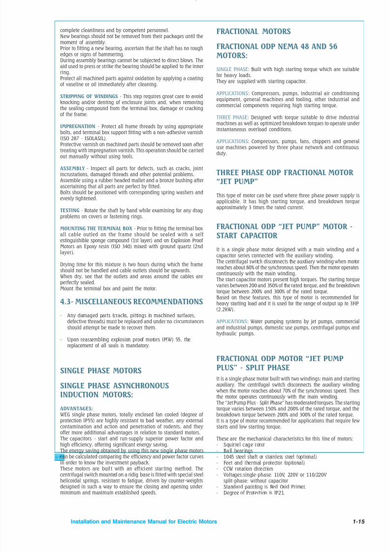
8/15/2019 r1_OF 71289_6 FF-AHF
http://slidepdf.com/reader/full/r1of-712896-ff-ahf 148/333
1-15Installation and Maintenance Manual for Electric Motors
complete cleanliness and by competent personnel.New bearings should not be removed from their packages until themoment of assembly.Prior to fitting a new bearing, ascertain that the shaft has no roughedges or signs of hammering.During assembly bearings cannot be subjected to direct blows. Theaid used to press or strike the bearing should be applied to the innerring.Protect all machined parts against oxidation by applying a coatingof vaseline or oil immediately after cleaning.
STRIPPING OF WINDINGS- This step requires great care to avoidknocking and/or denting of enclosure joints and, when removingthe sealing compound from the terminal box, damage or crackingof the frame.
IMPREGNATION- Protect all frame threads by using appropriatebolts, and terminal box support fitting with a non-adhesive varnish(ISO 287 - ISOLASIL).Protective varnish on machined parts should be removed soon aftertreating with impregnation varnish. This operation should be carriedout manually without using tools.
ASSEMBLY- Inspect all parts for defects, such as cracks, jointincrustations, damaged threads and other potential problems.Assemble using a rubber headed mallet and a bronze bushing afterascertaining that all parts are perfect by fitted.Bolts should be positioned with corresponding spring washers andevenly tightened.
TESTING- Rotate the shaft by hand while examining for any dragproblems on covers or fastening rings.
MOUNTING THE TERMINAL BOX- Prior to fitting the terminal box all cable outled on the frame should be sealed with a self estinguishible sponge compound (1st layer) and on Explosion Proof Motors an Epoxy resin (ISO 340) mixed with ground quartz (2ndlayer).
Drying time for this mixture is two hours during which the frameshould not be handled and cable outlets should be upwards.
When dry, see that the outlets and areas around the cables areperfectly sealed.Mount the terminal box and paint the motor.
4.3- MISCELLANEOUS RECOMMENDATIONS
- Any damaged parts (cracks, pittings in machined surfaces,defective threads) must be replaced and under no circumstancesshould attempt be made to recover them.
- Upon reassembling explosion proof motors IP(W) 55, thereplacement of all seals is mandatory.
SINGLE PHASE MOTORS
SINGLE PHASE ASYNCHRONOUSINDUCTION MOTORS:
ADVANTAGES:WEG single phase motors, totally enclosed fan cooled (degree of protection IP55) are highly resistant to bad weather, any externalcontamination and action and penetration of rodents, and they offer more additional advantages in relation to standard motors.
The capacitors - start and run-supply superior power factor andhigh efficiency, offering significant energy saving.
The energy saving obtained by using this new single phase motorscan be calculated comparing the efficiency and power factor curvesin order to know the investment payback.
These motors are buil t with an eff icient star ting method. Thecentrifugal switch mounted on a ridig base is fitted with special steelhelicoidal springs, resistant to fatigue, driven by counter-weightsdesigned in such a way to ensure the closing and opening underminimum and maximum established speeds.
FRACTIONAL MOTORS
FRACTIONAL ODP NEMA 48 AND 56MOTORS:
SINGLE PHASE: Built with high starting torque which are suitablefor heavy loads.
They are supplied with starting capacitor.
APPLICATIONS: Compressors, pumps, industrial air conditioningequipment, general machines and tooling, other industrial andcommercial components requiring high starting torque.
THREE PHASE: Designed with torque suitable to drive industrialmachines as well as optimized breakdown torques to operate underinstantaneous overload conditions.
APPLICATIONS: Compressors, pumps, fans, chippers and generaluse machines powered by three phase network and continuousduty.
THREE PHASE ODP FRACTIONAL MOTOR
“JET PUMP” This type of motor can be used where three phase power supply isapplicable. It has high starting torque, and breakdown torqueapproximately 3 times the rated current.
FRACTIONAL ODP “JET PUMP” MOTOR -START CAPACITOR
It is a single phase motor designed with a main winding and acapacitor series connected with the auxiliary winding.
The centrifugal switch disconnects the auxiliary winding when motorreaches about 80% of the synchronous speed. Then the motor operatescontinuously with the main winding.
The start capacitor motors present high torques. The starting torque varies between 200 and 350% of the rated torque, and the breakdowntorque between 200% and 300% of the rated torque.Based on these features, this type of motor is recommended forheavy starting load and it is used for the range of output up to 3HP(2.2kW).
APPLICATIONS: Water pumping systems by jet pumps, commercialand industrial pumps, domestic use pumps, centrifugal pumps andhydraulic pumps.
FRACTIONAL ODP MOTOR “JET PUMP
PLUS” - SPLIT PHASEIt is a single phase motor built with two windings: main and startingauxiliary. The centrifugal switch disconnects the auxiliary winding
when the motor reaches about 70% of the synchronous speed. Thenthe motor operates continuously with the main winding.
The “Jet Pump Plus - Split Phase” has moderated torques. The startingtorque varies between 150% and 200% of the rated torque, and thebreakdown torque between 200% and 300% of the rated torque.It is a type of motor recommended for applications that require few starts and low starting torque.
These are the mechanical characteristics for this line of motors:- Squirrel cage rotor- Ball bearings- 1045 steel shaft or stainless steel (optional)- Feet and thermal protector (optional)- CCW rotation direction- Voltages:single-phase: 110V, 220V or 110/220V
split-phase: without capacitor- Standard painting is Red Oxid Primer.- Degree of Protection is IP21.

8/15/2019 r1_OF 71289_6 FF-AHF
http://slidepdf.com/reader/full/r1of-712896-ff-ahf 149/333
1-16 Installation and Maintenance Manual for Electric Motors
THREE PHASE MOTOR - PREMIUM HIGHEFFICIENCY
Standard Features:- Frequency: 60Hz and 50Hz- Voltages: 220/380V, 380/660V, 440/760V or 220/380/440V- Service Factor: 1.0- Class of insulation: “F”- Degree of Protection: IP55- Design N (IEC 85)- Speeds: 60Hz: 3600, 1800, 1200 and 900 rpm
50Hz: 3000,1500,1000 and 750 rpm- Temperature rise: below 80ºC
Optional Features:- Class of insulation: “H”- Degree of Protection: IP(W)55- Thermal protection: Thermostats or thermistors- Space heaters- Routine and type test (IEC 34-2), witnessed or not.
Optional Features on Request:- Design: H
- Hazardous location motors- Explosion proof motors- Increased safety - Marine duty motors
THREE PHASE BRAKE MOTORS -Single Disc
GENERAL DESCRIPTION: The brake motor is composed of an induction motor coupled to asingle disc brake forming an integral and compact unit.
The induction motor is a totally enclosed fan cooled motor with thesame mechanical and electrical performance of the WEG standardmotors.
The brake is built with few movable parts which gives long life withreduced maintenance. The two faces of the brake pads create alarge contact area which reduces the pressure over them, reducesthe heating and the wear is minimum.Besides, the brake is cooled by the same motor cooling.
The electromagnet drive coil, protected with epoxy resin, operatescontinuously with voltages varying 10% above and below the rated
voltage. It is DC powered, supplied by a bridge rectifier made of silicon diodes and varistors which avoid sudden voltage peaks andallow a quick current switching off.
The DC power supply gives the brake a quicker and uniformoperation.
APPLICATIONS:Brake motors are commonly used on: tooling-machines, sewingmachines, packing machines, conveyors, bottle washing machines,
winding machines, folding machines, hoists, rol ling bri dges,
elevators, printing machines and others. In general terms, onequipment requiring quick stops based on safety, positioning andtime saving factors.
BRAKE OPERATION:When motor is switched off from power supply, the control alsointerrupts the coil current and then the electromagnet stops operating.
The pressure springs force the armature towards the motor nondrive endshield. The braking pads, which are fitted in the brakingdisc, are compressed between the two friction surfaces, the armatureand the endshield braking the motor until it stops.
The arm ature is pul led against the ele ctr oma gne t fra me by eliminating the spring resistance. Once they are free, the brakingpads move axially in their fittings and they stay out of the frictionarea.In this way, the braking is finished permitting the motor to startfreely.As an option, WEG can supply lining braking disc.
INSTALLATION:Brake motors can be mounted in any position as long as it is notsubject to penetration of water, oil, abrasive dust, etc through theair inlet.
When normally mounted, the brake motor complies with Degree of Protection IP54 of IEC.
CONNECTION DIAGRAM The WEG Brakemotor all ows 3 types of connec tion dia gramsupplying slow, medium and quick brakings.
a) Slow Braking The feeding of the brake coil bridge rectifier is done directly fromthe motor terminals, without interruption, as shown below:
D- Bridge rectifierR- VaristorsL- Electromagnet coilK- ContactorS1- NO auxiliary contact.
Fig 2 - Connection diagram for medium braking.
c) Quick Braking:A contact for interruption is directly fitted in one of the coil feedingcables in the DC circuit.It is essential that this is a NO auxiliary contact of the contactoritself or motor magnetic switch.
D - Bridge rectifierR - VaristorsL - Electromagnet coilK - ContactorS1 - NO auxiliary contact
Fig. 3 - Connection Diagram for quick braking .
D - Bridge rectifierR - VaristorsL - Electromagnet coilK - Contactor
Fig. 1 - Connection diagram for slow braking
b) Medium Braking:In this case a contact for interruption of the bridge rectifier feedingcurrent in the AC circuit is fitted. It is essential that this be a NOauxiliar contact of the contactor itself or motor magnetic switch inorder to allow switch on and off of brake and motor simultaneously.
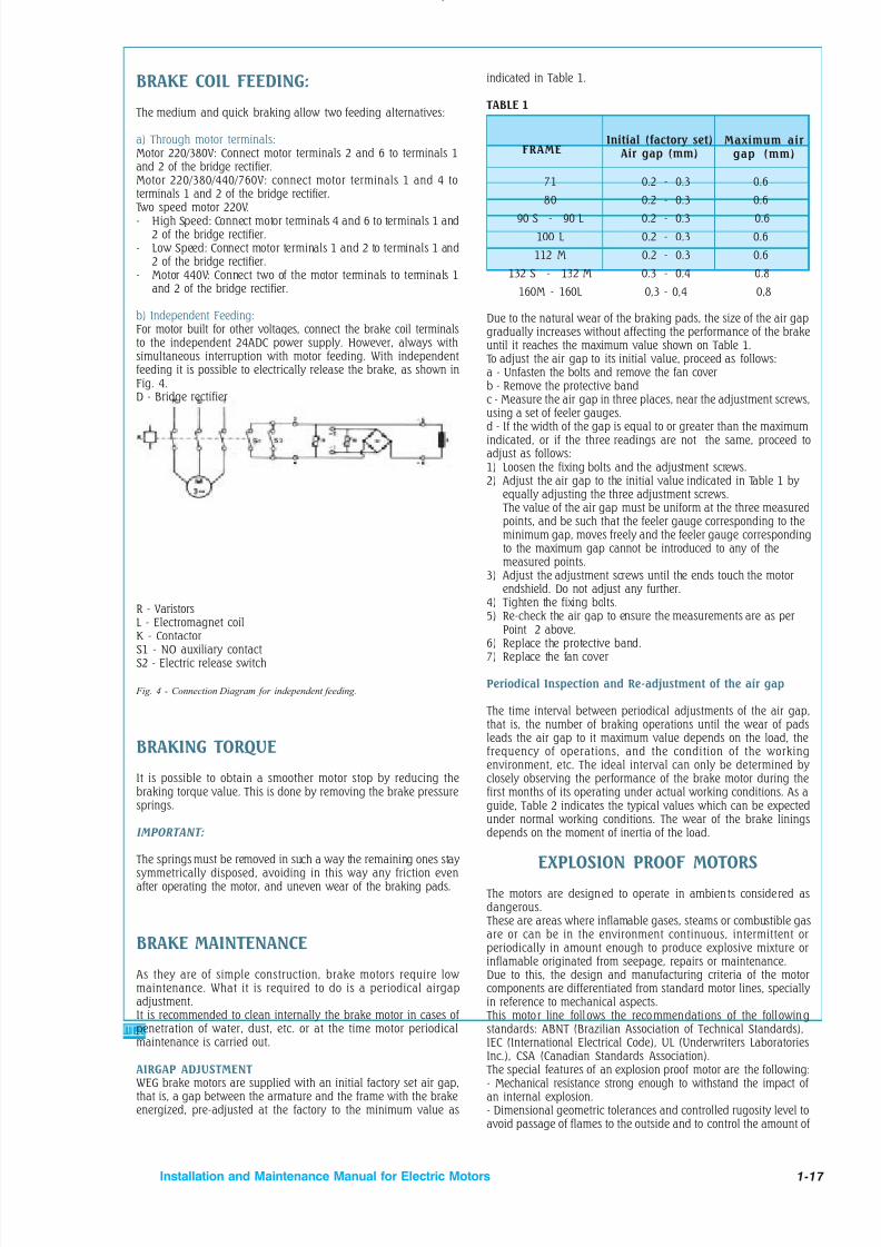
8/15/2019 r1_OF 71289_6 FF-AHF
http://slidepdf.com/reader/full/r1of-712896-ff-ahf 150/333
1-17Installation and Maintenance Manual for Electric Motors
BRAKE COIL FEEDING:
The medium and quick braking allow two feeding alternatives:
a) Through motor terminals:Motor 220/380V: Connect motor terminals 2 and 6 to terminals 1and 2 of the bridge rectifier.Motor 220/380/440/760V: connect motor terminals 1 and 4 toterminals 1 and 2 of the bridge rectifier.
Two speed motor 220V.- High Speed: Connect motor terminals 4 and 6 to terminals 1 and
2 of the bridge rectifier.- Low Speed: Connect motor terminals 1 and 2 to terminals 1 and
2 of the bridge rectifier.- Motor 440V: Connect two of the motor terminals to terminals 1
and 2 of the bridge rectifier.
b) Independent Feeding:For motor built for other voltages, connect the brake coil terminalsto the independent 24ADC power supply. However, always withsimultaneous interruption with motor feeding. With independentfeeding it is possible to electrically release the brake, as shown inFig. 4.D - Bridge rectifier
Maximum air gap (mm)
71 0.2 - 0.3 0.680 0.2 - 0.3 0.6
90 S - 90 L 0.2 - 0.3 0.6100 L 0.2 - 0.3 0.6112 M 0.2 - 0.3 0.6
132 S - 132 M 0.3 - 0.4 0.8160M - 160L 0,3 - 0,4 0,8
indicated in Table 1.
TABLE 1
Due to the natural wear of the braking pads, the size of the air gapgradually increases without affecting the performance of the brakeuntil it reaches the maximum value shown on Table 1.
To adjust the air gap to its initial value, proceed as follows:a - Unfasten the bolts and remove the fan coverb - Remove the protective bandc - Measure the air gap in three places, near the adjustment screws,
using a set of feeler gauges.d - If the width of the gap is equal to or greater than the maximumindicated, or if the three readings are not the same, proceed toadjust as follows:1) Loosen the fixing bolts and the adjustment screws.2) Adjust the air gap to the initial value indicated in Table 1 by
equally adjusting the three adjustment screws. The value of the air gap must be uniform at the three measuredpoints, and be such that the feeler gauge corresponding to theminimum gap, moves freely and the feeler gauge correspondingto the maximum gap cannot be introduced to any of themeasured points.
3) Adjust the adjustment screws until the ends touch the motorendshield. Do not adjust any further.
4) Tighten the fixing bolts.5) Re-check the air gap to ensure the measurements are as per
Point 2 above.6) Replace the protective band.7) Replace the fan cover
Periodical Inspection and Re-adjustment of the air gap
The time interval between periodical adjustments of the air gap,that is, the number of braking operations until the wear of padsleads the air gap to it maximum value depends on the load, thefrequency of operations, and the condition of the workingenvironment, etc. The ideal interval can only be determined by closely observing the performance of the brake motor during thefirst months of its operating under actual working conditions. As aguide, Table 2 indicates the typical values which can be expectedunder normal working conditions. The wear of the brake linings
depends on the moment of inertia of the load.
EXPLOSION PROOF MOTORS
The motors are designed to operate in ambients considered asdangerous.
These are areas where inflamable gases, steams or combustible gasare or can be in the environment continuous, intermittent orperiodically in amount enough to produce explosive mixture orinflamable originated from seepage, repairs or maintenance.Due to this, the design and manufacturing criteria of the motorcomponents are differentiated from standard motor lines, specially in reference to mechanical aspects.
This motor line follows the recommendations of the followingstandards: ABNT (Brazilian Association of Technical Standards),
IEC (International Electrical Code), UL (Underwriters LaboratoriesInc.), CSA (Canadian Standards Association).
The special features of an explosion proof motor are the following:- Mechanical resistance strong enough to withstand the impact of an internal explosion.- Dimensional geometric tolerances and controlled rugosity level toavoid passage of flames to the outside and to control the amount of
R - Varistors
L - Electromagnet coilK - ContactorS1 - NO auxiliary contactS2 - Electric release switch
Fig. 4 - Connection Diagram for independent feeding.
BRAKING TORQUE
It is possible to obtain a smoother motor stop by reducing thebraking torque value. This is done by removing the brake pressuresprings.
IMPORTANT:
The springs must be removed in such a way the remaining ones stay symmetrically disposed, avoiding in this way any friction evenafter operating the motor, and uneven wear of the braking pads.
BRAKE MAINTENANCE
As they are of simple construction, brake motors require low maintenance. What it is required to do is a periodical airgapadjustment.It is recommended to clean internally the brake motor in cases of penetration of water, dust, etc. or at the time motor periodical
maintenance is carried out.
AIRGAP ADJUSTMENT WEG brake motors are supplied with an initial factory set air gap,that is, a gap between the armature and the frame with the brakeenergized, pre-adjusted at the factory to the minimum value as
FRAMEInitial (factory set)
Air gap (mm)
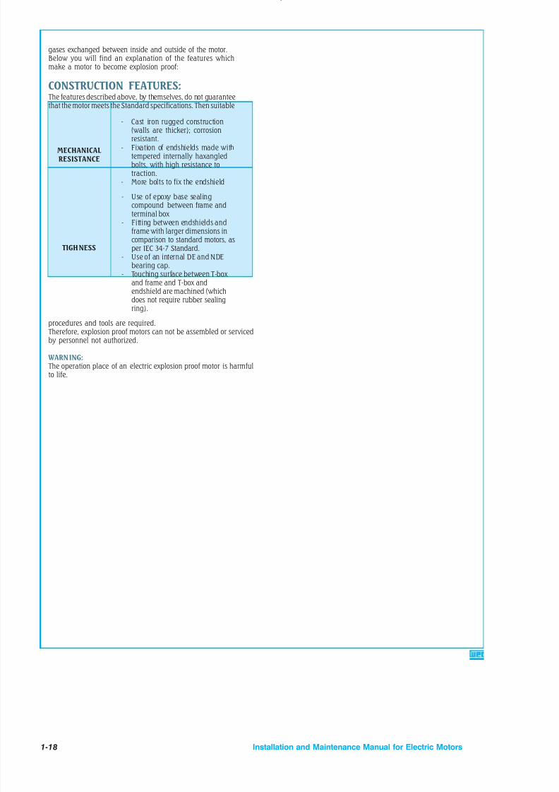
8/15/2019 r1_OF 71289_6 FF-AHF
http://slidepdf.com/reader/full/r1of-712896-ff-ahf 151/333

8/15/2019 r1_OF 71289_6 FF-AHF
http://slidepdf.com/reader/full/r1of-712896-ff-ahf 152/333
1-19Installation and Maintenance Manual for Electric Motors
ABNORMAL SITUATION POSSIBLE CAUSES
- Lack of voltage on motor terminals- Low feeding voltage- Wrong connection- Incorrect numbering of leads- Excessive load- Open stationary switch- Damaged capacitor- Auxiliary coil interrupted
MOTOR DOES NOT START
- Incorrect internal connection- Failed rotor- Rotor out of center- Voltage below the rated voltage- Frequency below the rated frequency - Frequency above the rated frequency - Capacitance below that specified- Capacitors series connected instead of parallel
LOW STARTING TORQUE
- Failed rotor- Rotor with bar inclination above that specified- Rotor out of center- Voltage below the rated voltage
- Run capacitor below that specified
LOW BREAKDOWN TORQUE
- Voltage out of the rated voltage- Overload- Frequency out of the rated frequency - Belts excessively tightened- Rotor rubbing on the stator
- Air gap above that specified- Voltage above that specified- Frequency below that specified- Wrong internal connection- Rotor out of center- Rotor rubbing on the stator- Defective bearing- Endbells fitted under pressure or badly fitted- Steel magnetic lamination without treatment- Run capacitor out of that specified- Stationary/centrifugal switch do not open
HIGH CURRENT UNDER LOAD
HIGH NO LOAD CURRENT
- Damaged slot insulating materials- Cut leads- Coil head touching the motor frame- Humidity or chemical agents present- Dust on the winding
LOW INSULATION RESISTANCE
5 - ABNORMAL SITUATIONS DURING OPERATIONANALYSIS OF SOME ABNORMAL SITUATIONS AND
POSSIBLE CAUSES ON ELECTRIC MOTORS:

8/15/2019 r1_OF 71289_6 FF-AHF
http://slidepdf.com/reader/full/r1of-712896-ff-ahf 153/333
1-20 Installation and Maintenance Manual for Electric Motors
- Excessive amount of grease- Excessive axial thrust or radial force of the belt- Bent shaft- Loose endbells or out of center
- Lack of grease- Foreign bodies in the grease
BEARING HEATING
- Obstructed ventilation- Smaller size fan- Voltage or frequency out of that specified- Rotor rubbing on the shaft- Failed rotor- Stator with insufficient impregnation- Overload- Defective bearing- Consecutive starts- Air gap below that specified- Improper run capacitor- Wrong connections
MOTOR OVERHEATING
- Rotor out of center- Unbalance power supply voltage- Failed rotor- Wrong connections- Unbalanced rotor- Bearing housing with excessive clearance- Rotor rubbing on the stator- Bent shaft- Stator laminations loose- Use of fractional groups on run capacitorsingle-phase winding
EXCESSIVE VIBRATION
- Unbalancing- Bent shaft- Incorrect alignment- Rotor out of center- Wrong connections- Foreign bodies in the air gap- Foreign bodies between fan and fan cover- Worn bearings- Improper slots combination- Inadequate aerodynamic
HIGH NOISE LEVEL
ABNORMAL SITUATION POSSIBLE CAUSES

8/15/2019 r1_OF 71289_6 FF-AHF
http://slidepdf.com/reader/full/r1of-712896-ff-ahf 154/333
1-21Installation and Maintenance Manual for Electric Motors
Leaving the factory in perfect conditions is not enough for the electric motor. Although the high quality standard assured by Weg for several years of operation, there will be a day when the motor will requireservice: This can be corrective, preventive or orientative.Weg gives great inportance to service as this makes part of a successful sale.Weg service is immediate and efficient.At the moment you buy a Weg electric motor, you are also receiving an uncomparable know-how developedin the company and you will count on our authorized services during the whole motor operating life,carefully selected and strategically located in more than fifty countries.
SERVICE
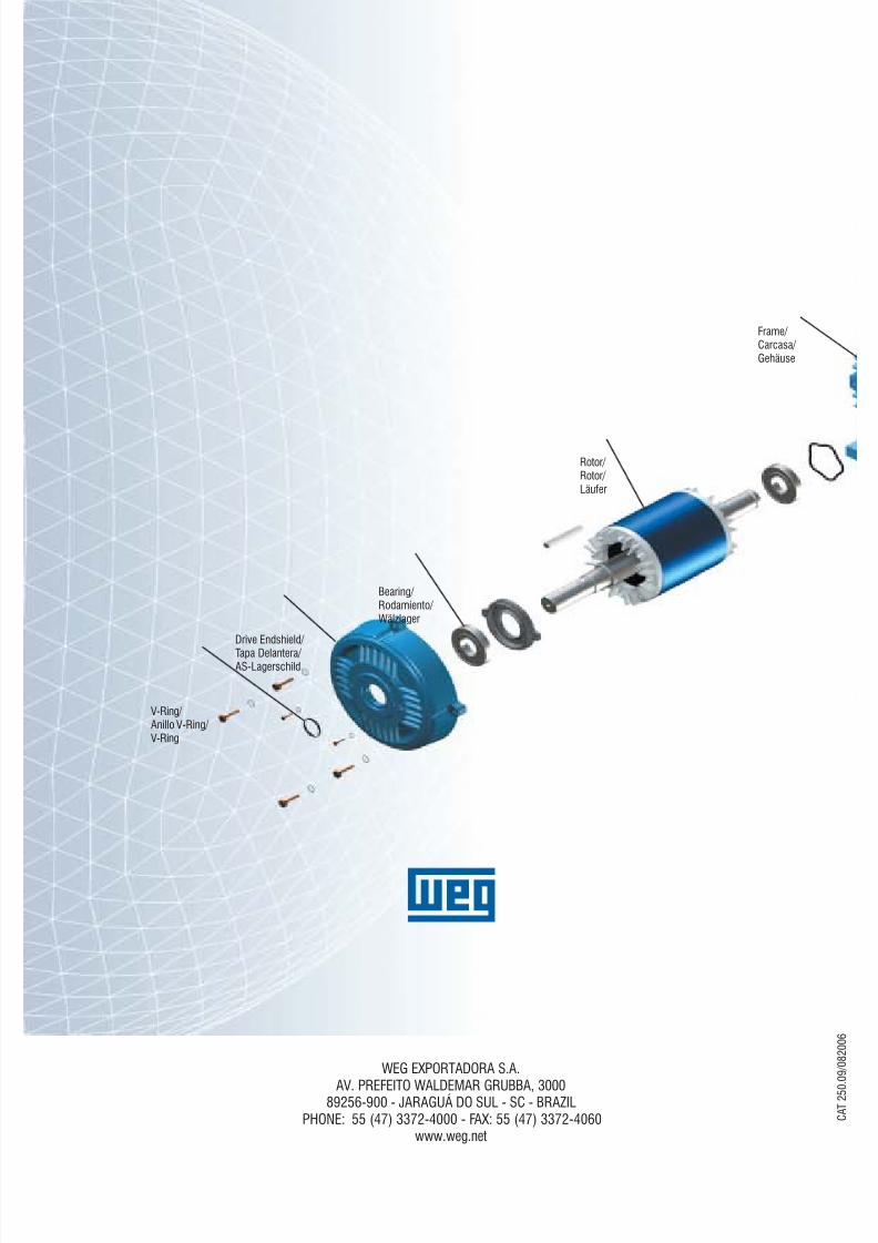
8/15/2019 r1_OF 71289_6 FF-AHF
http://slidepdf.com/reader/full/r1of-712896-ff-ahf 155/333
WEG EXPORTADORA S.A.AV. PREFEITO WALDEMAR GRUBBA, 3000
89256-900 - JARAGUÁ DO SUL - SC - BRAZILPHONE: 55 (47) 3372-4000 - FAX: 55 (47) 3372-4060
www.weg.net C A T 2 5
0 . 0
9 / 0 8 2 0 0 6
Drive Endshield/ Tapa Delantera/ AS-Lagerschild
V-Ring/ Anillo V-Ring/ V-Ring
Bearing/ Rodamiento/
Wälzlager
Rotor/ Rotor/ Läufer
Frame/ Carcasa/ Gehäuse
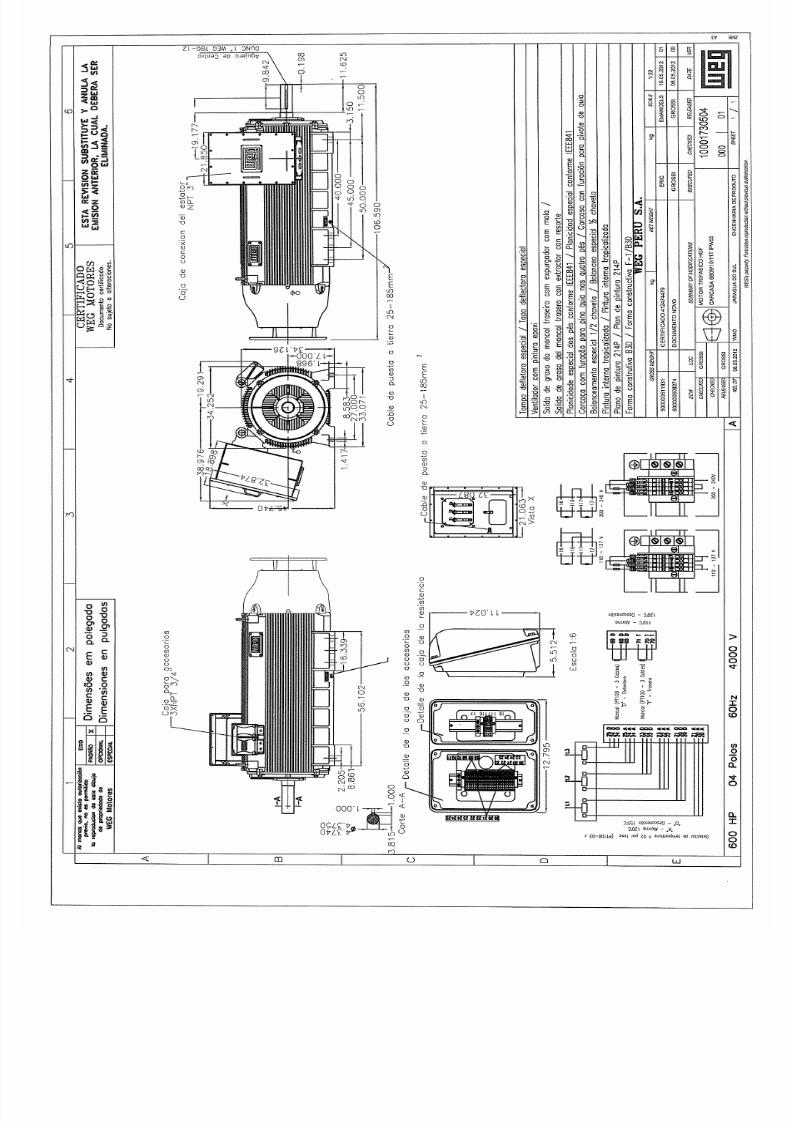
8/15/2019 r1_OF 71289_6 FF-AHF
http://slidepdf.com/reader/full/r1of-712896-ff-ahf 156/333
8/15/2019 r1_OF 71289_6 FF-AHF
http://slidepdf.com/reader/full/r1of-712896-ff-ahf 157/333
Weir Minerals Latin AmericaVulco Perú S.A.
ExcellentMineralsSolutions
Manual de Operaciones y Mantenimiento
ReductorGear Box
Av. Separadora Industrial 2201Ate – Lima, Perú
T: +51 (1) 6187575E: [email protected]
W: www.weirminerals.com

8/15/2019 r1_OF 71289_6 FF-AHF
http://slidepdf.com/reader/full/r1of-712896-ff-ahf 158/333
Documentation
Kunde /Customer Siemens Peru
Kunden-Bestell-Nr. /Customer purchase order no.
4500079515
Siemens Auftrags-Nr. /Siemens order no. 4638126
Baujahr /Year of manufacture 2012
Voerde / Friedrichsfeld 2012-03-02
Siemens AG . D 46393 Bocholt . Tel. 02871/92-0 . http://www.siemens.com
1

8/15/2019 r1_OF 71289_6 FF-AHF
http://slidepdf.com/reader/full/r1of-712896-ff-ahf 159/333
DokumentationsübersichtDocumentation chart
Bauart / Type
Größe / Size
Bei Korrespondenz bitte angeben / Please quote in correspondence No. 4638126 EN
SIEMENS AG, I DT MD AP DA OM DOC, D - 46393 Bocholt Datum/Date Name Abt.Tel. 02871/92-0; TX 0813841; Fax 02871/921551 02.03.12 Bungert DAOD.FR
This page is left blank on purpose.
2
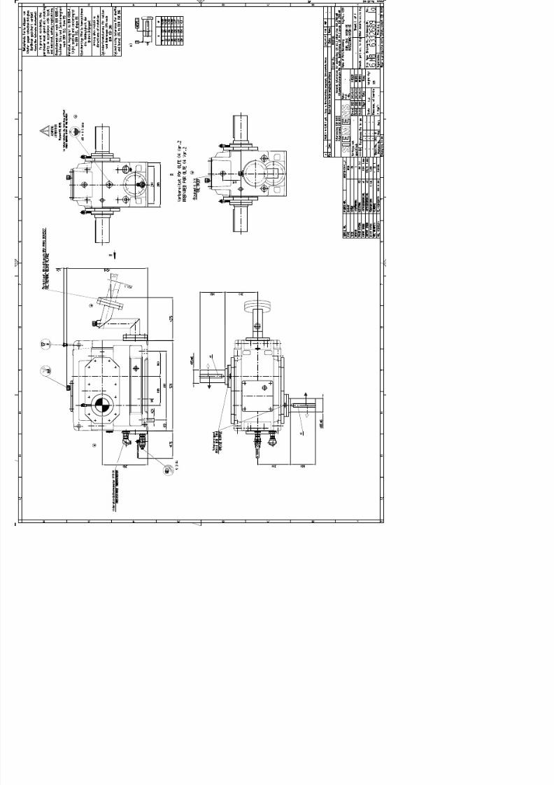
8/15/2019 r1_OF 71289_6 FF-AHF
http://slidepdf.com/reader/full/r1of-712896-ff-ahf 160/333

8/15/2019 r1_OF 71289_6 FF-AHF
http://slidepdf.com/reader/full/r1of-712896-ff-ahf 161/333

8/15/2019 r1_OF 71289_6 FF-AHF
http://slidepdf.com/reader/full/r1of-712896-ff-ahf 162/333
FLENDER gear units
Gear UnitH.SH, H.VH, H.HH, H.DH, H.KH, H.FH, H.HM,H.DM, H.KM, H.FM, H.PH, B.SH, B.VH, B.HH,B.DH, B.KH, B.FH, B.HM, B.DM, B.KM, B.FM,T.SH, T.HH, T.KH, T.DH, T.FHSizes 1 to 22
Assembly and operating instructionsBA 5010 en 06/2010
32

8/15/2019 r1_OF 71289_6 FF-AHF
http://slidepdf.com/reader/full/r1of-712896-ff-ahf 163/333
2 / 94BA 5010 en 06/2010
Gear Unit
H.SH, H.VH, H.HH, H.DH, H.KH, H.FH,H.HM, H.DM, H.KM, H.FM, H.PH, B.SH,B.VH, B.HH, B.DH, B.KH, B.FH, B.HM,B.DM, B.KM, B.FM, T.SH, T.HH, T.KH,T.DH, T.FHSizes 1 to 22
Assembly and operating instructionsTranslation of the original assembly and operating instructions
Technical data
Spare parts,customer service
Maintenanceand repair
Faults, causesand remedy
Operation
Start-up
Fitting
Technicaldescription
Transport andstorage
Safety instructions
General notes
Declarations
1
12
11
10
9
8
7
6
5
4
3
2
33
8/15/2019 r1_OF 71289_6 FF-AHF
http://slidepdf.com/reader/full/r1of-712896-ff-ahf 164/333
3 / 94BA 5010 en 06/2010
Notes and symbols in these assembly and operating instructions
Note: The term "Assembly and operating instructions" will in the following also be shortened to "instructions"or "manual".
Legal notes
Warning note conceptThis manual comprises notes which must be observed for your personal safety and for preventing material damage.Notes for your personal safety are marked with a warning triangle or an "Ex" symbol (when applyingDirective 94/9/EC), those only for preventing material damage with a "STOP" sign.
WARNING! Imminent explosion!
The notes indicated by this symbol are given to prevent explosion damage.Disregarding these notes may result in serious injury or death.
WARNING! Imminent personal injury!
The notes indicated by this symbol are given to prevent personal injury.Disregarding these notes may result in serious injury or death.
WARNING! Imminent damage to the product!
The notes indicated by this symbol are given to prevent damage to the product.Disregarding these notes may result in material damage.
NOTE!
The notes indicated by this symbol must be treated as general operating information .Disregarding these notes may result in undesirable results or conditions.
WARNING! Hot surfaces!
The notes indicated by this symbol are made to prevent risk of burns due to hot surfacesand must always be observed.Disregarding these notes may result in light or serious injury.
Where there is more than one hazard, the warning note for whichever hazard is the most serious is always used.If in a warning note a warning triangle is used to warn of possible personal injury, a warning of material damage maybe added to the same warning note.
Qualified personnelThe product or system to which these instructions relate may be handled only by persons qualified for the work
concerned and in accordance with the instructions relating to the work concerned, particularly the safety andwarning notes contained in those instructions. Qualified personnel must be specially trained and have theexperience necessary to recognise risks associated with these products or systems and to avoid possible hazards.
34

8/15/2019 r1_OF 71289_6 FF-AHF
http://slidepdf.com/reader/full/r1of-712896-ff-ahf 165/333
4 / 94BA 5010 en 06/2010
Intended use of Siemens productsObserve also the following:
Siemens products must be used only for the applications provided for in the catalogue and the relevanttechnical documentation. If products and components of other makes are used, they must berecommended or approved by Siemens. The faultfree, safe operation of the products calls for propertransport, proper storage, erection, assembly, installation, start-up, operation and maintenance. Thepermissible ambient conditions must be adhered to. Notes in the relevant documentations must be
observed.
TrademarksAll designations indicated with the registered industrial property mark ® are registered trademarks of Siemens AG.Other designations used in these instructions may be trademarks the use of which by third parties for their ownpurposes may infringe holders’ rights.
Exclusion of liabilityWe have checked the content of the instructions for compliance with the hard- and software described.Nevertheless, variances may occur, and so we can offer no warranty for complete agreement. The informationgiven in these instructions is regularly checked, and any necessary corrections are included in subsequent editions.
Symbols
Earth connection point Air relief point yellow
Oil-filling point yellow Oil-draining point white
Oil level red Oil level red
Oil overflow Connection forvibration-monitoring device
Lubrication point red Apply grease
Lifting eye Eye bolt
Do not unscrew
Alignment surface, horizontal Alignment surface, vertical
These symbols indicate the oil-level checking procedure using the oil dipstick.
These symbols indicate that the oil dipstick must always be firmly screwed in.
35

8/15/2019 r1_OF 71289_6 FF-AHF
http://slidepdf.com/reader/full/r1of-712896-ff-ahf 166/333
5 / 94BA 5010 en 06/2010
Contents
1. Technical data 9. . . . . . . . . . . . . . . . . . . . . . . . . . . . . . . . . . . . . . . . . . . . . . . . . . . . .1.1 General technical data 9. . . . . . . . . . . . . . . . . . . . . . . . . . . . . . . . . . . . . . . . . . . . . . . . . . . . . . . . . . . . . . .1.2 Configurations and weights 10. . . . . . . . . . . . . . . . . . . . . . . . . . . . . . . . . . . . . . . . . . . . . . . . . . . . . . . . . . .1.2.1 Types 10. . . . . . . . . . . . . . . . . . . . . . . . . . . . . . . . . . . . . . . . . . . . . . . . . . . . . . . . . . . . . . . . . . . . . . . . . . . . .1.2.2 Weights 11. . . . . . . . . . . . . . . . . . . . . . . . . . . . . . . . . . . . . . . . . . . . . . . . . . . . . . . . . . . . . . . . . . . . . . . . . . .
1.2.3 Measuring-surface sound-pressure level 13. . . . . . . . . . . . . . . . . . . . . . . . . . . . . . . . . . . . . . . . . . . . . . .1.2.3.1 Measuring-surface sound-pressure level for bevel-helical gear units (B...) with fan 13. . . . . . . . . . . .1.2.3.2 Measuring-surface sound-pressure level for bevel-helical gear units (B...) without fan 14. . . . . . . . .1.2.3.3 Measuring-surface sound-pressure level for helical-gear units (H...) with fan 15. . . . . . . . . . . . . . . . .1.2.3.4 Measuring-surface sound-pressure level for helical-gear units (H...) without fan 16. . . . . . . . . . . . . .
2. General notes 17. . . . . . . . . . . . . . . . . . . . . . . . . . . . . . . . . . . . . . . . . . . . . . . . . . . . .2.1 Introduction 17. . . . . . . . . . . . . . . . . . . . . . . . . . . . . . . . . . . . . . . . . . . . . . . . . . . . . . . . . . . . . . . . . . . . . . . .2.2 Copyright 17. . . . . . . . . . . . . . . . . . . . . . . . . . . . . . . . . . . . . . . . . . . . . . . . . . . . . . . . . . . . . . . . . . . . . . . . . .
3. Safety instructions 18. . . . . . . . . . . . . . . . . . . . . . . . . . . . . . . . . . . . . . . . . . . . . . . . .3.1 Obligations of the user 18. . . . . . . . . . . . . . . . . . . . . . . . . . . . . . . . . . . . . . . . . . . . . . . . . . . . . . . . . . . . . . .3.2 Environmental protection 19. . . . . . . . . . . . . . . . . . . . . . . . . . . . . . . . . . . . . . . . . . . . . . . . . . . . . . . . . . . . .
3.3 Special dangers and personal protective equipment 19. . . . . . . . . . . . . . . . . . . . . . . . . . . . . . . . . . . . . .4. Transport and storage 20. . . . . . . . . . . . . . . . . . . . . . . . . . . . . . . . . . . . . . . . . . . . .4.1 Scope of supply 20. . . . . . . . . . . . . . . . . . . . . . . . . . . . . . . . . . . . . . . . . . . . . . . . . . . . . . . . . . . . . . . . . . . .4.2 Transport 20. . . . . . . . . . . . . . . . . . . . . . . . . . . . . . . . . . . . . . . . . . . . . . . . . . . . . . . . . . . . . . . . . . . . . . . . . .4.3 Storing the gear unit 22. . . . . . . . . . . . . . . . . . . . . . . . . . . . . . . . . . . . . . . . . . . . . . . . . . . . . . . . . . . . . . . . .4.4 Standard coating and preservation 23. . . . . . . . . . . . . . . . . . . . . . . . . . . . . . . . . . . . . . . . . . . . . . . . . . . .4.4.1 Interior preservation with preservative agent 24. . . . . . . . . . . . . . . . . . . . . . . . . . . . . . . . . . . . . . . . . . . .4.4.2 Exterior preservation 24. . . . . . . . . . . . . . . . . . . . . . . . . . . . . . . . . . . . . . . . . . . . . . . . . . . . . . . . . . . . . . . .
5. Technical description 25. . . . . . . . . . . . . . . . . . . . . . . . . . . . . . . . . . . . . . . . . . . . . .5.1 General description 25. . . . . . . . . . . . . . . . . . . . . . . . . . . . . . . . . . . . . . . . . . . . . . . . . . . . . . . . . . . . . . . . .5.2 Output designs 26. . . . . . . . . . . . . . . . . . . . . . . . . . . . . . . . . . . . . . . . . . . . . . . . . . . . . . . . . . . . . . . . . . . . .
5.3 Housing 26. . . . . . . . . . . . . . . . . . . . . . . . . . . . . . . . . . . . . . . . . . . . . . . . . . . . . . . . . . . . . . . . . . . . . . . . . . .5.4 Toothed components 30. . . . . . . . . . . . . . . . . . . . . . . . . . . . . . . . . . . . . . . . . . . . . . . . . . . . . . . . . . . . . . . .5.5 Lubrication 30. . . . . . . . . . . . . . . . . . . . . . . . . . . . . . . . . . . . . . . . . . . . . . . . . . . . . . . . . . . . . . . . . . . . . . . . .5.5.1 Splash lubrication 30. . . . . . . . . . . . . . . . . . . . . . . . . . . . . . . . . . . . . . . . . . . . . . . . . . . . . . . . . . . . . . . . . . .5.5.2 Pressure lubrication through add-on oil-supply system 30. . . . . . . . . . . . . . . . . . . . . . . . . . . . . . . . . . . .5.6 Shaft bearings 31. . . . . . . . . . . . . . . . . . . . . . . . . . . . . . . . . . . . . . . . . . . . . . . . . . . . . . . . . . . . . . . . . . . . . .5.7 Shaft seals 31. . . . . . . . . . . . . . . . . . . . . . . . . . . . . . . . . . . . . . . . . . . . . . . . . . . . . . . . . . . . . . . . . . . . . . . . .5.7.1 Radial shaft-sealing rings 31. . . . . . . . . . . . . . . . . . . . . . . . . . . . . . . . . . . . . . . . . . . . . . . . . . . . . . . . . . . .5.7.2 Labyrinth seals 31. . . . . . . . . . . . . . . . . . . . . . . . . . . . . . . . . . . . . . . . . . . . . . . . . . . . . . . . . . . . . . . . . . . . .5.7.3 Taconite seals 32. . . . . . . . . . . . . . . . . . . . . . . . . . . . . . . . . . . . . . . . . . . . . . . . . . . . . . . . . . . . . . . . . . . . . .5.7.4 Tacolab seal 33. . . . . . . . . . . . . . . . . . . . . . . . . . . . . . . . . . . . . . . . . . . . . . . . . . . . . . . . . . . . . . . . . . . . . . .5.8 Backstop 34. . . . . . . . . . . . . . . . . . . . . . . . . . . . . . . . . . . . . . . . . . . . . . . . . . . . . . . . . . . . . . . . . . . . . . . . . .5.9 Torque-limiting backstop (special design) 35. . . . . . . . . . . . . . . . . . . . . . . . . . . . . . . . . . . . . . . . . . . . . .5.10 Cooling 36. . . . . . . . . . . . . . . . . . . . . . . . . . . . . . . . . . . . . . . . . . . . . . . . . . . . . . . . . . . . . . . . . . . . . . . . . . . .5.10.1 Fan 36. . . . . . . . . . . . . . . . . . . . . . . . . . . . . . . . . . . . . . . . . . . . . . . . . . . . . . . . . . . . . . . . . . . . . . . . . . . . . . .5.10.2 Cooling coil 37. . . . . . . . . . . . . . . . . . . . . . . . . . . . . . . . . . . . . . . . . . . . . . . . . . . . . . . . . . . . . . . . . . . . . . . .5.10.3 Add-on oil-supply system with air oil-cooler 38. . . . . . . . . . . . . . . . . . . . . . . . . . . . . . . . . . . . . . . . . . . . .5.10.4 Add-on oil-supply unit with water oil-cooler 40. . . . . . . . . . . . . . . . . . . . . . . . . . . . . . . . . . . . . . . . . . . . . .5.10.4.1 Pump 41. . . . . . . . . . . . . . . . . . . . . . . . . . . . . . . . . . . . . . . . . . . . . . . . . . . . . . . . . . . . . . . . . . . . . . . . . . . . .5.10.4.2 Water oil-cooler 41. . . . . . . . . . . . . . . . . . . . . . . . . . . . . . . . . . . . . . . . . . . . . . . . . . . . . . . . . . . . . . . . . . . . .5.10.4.3 Filter 41. . . . . . . . . . . . . . . . . . . . . . . . . . . . . . . . . . . . . . . . . . . . . . . . . . . . . . . . . . . . . . . . . . . . . . . . . . . . . .
36

8/15/2019 r1_OF 71289_6 FF-AHF
http://slidepdf.com/reader/full/r1of-712896-ff-ahf 167/333
6 / 94BA 5010 en 06/2010
5.11 Heating 41. . . . . . . . . . . . . . . . . . . . . . . . . . . . . . . . . . . . . . . . . . . . . . . . . . . . . . . . . . . . . . . . . . . . . . . . . . . .5.12 Oil-temperature monitoring 42. . . . . . . . . . . . . . . . . . . . . . . . . . . . . . . . . . . . . . . . . . . . . . . . . . . . . . . . . . .5.13 Oil-level monitoring system 43. . . . . . . . . . . . . . . . . . . . . . . . . . . . . . . . . . . . . . . . . . . . . . . . . . . . . . . . . . .5.14 Bearing-monitoring system 44. . . . . . . . . . . . . . . . . . . . . . . . . . . . . . . . . . . . . . . . . . . . . . . . . . . . . . . . . . .5.15 Speed transmitter 44. . . . . . . . . . . . . . . . . . . . . . . . . . . . . . . . . . . . . . . . . . . . . . . . . . . . . . . . . . . . . . . . . . .5.16 Auxiliary drive 45. . . . . . . . . . . . . . . . . . . . . . . . . . . . . . . . . . . . . . . . . . . . . . . . . . . . . . . . . . . . . . . . . . . . . .5.16.1 Auxiliary drive, designed as a maintenance drive 45. . . . . . . . . . . . . . . . . . . . . . . . . . . . . . . . . . . . . . . .5.16.2 Auxiliary drive, designed as a load drive 46. . . . . . . . . . . . . . . . . . . . . . . . . . . . . . . . . . . . . . . . . . . . . . . .
5.16.3 Overrunning clutch 47. . . . . . . . . . . . . . . . . . . . . . . . . . . . . . . . . . . . . . . . . . . . . . . . . . . . . . . . . . . . . . . . . .6. Fitting 48. . . . . . . . . . . . . . . . . . . . . . . . . . . . . . . . . . . . . . . . . . . . . . . . . . . . . . . . . . . . .6.1 General information on fitting 48. . . . . . . . . . . . . . . . . . . . . . . . . . . . . . . . . . . . . . . . . . . . . . . . . . . . . . . . .6.2 Unpacking 49. . . . . . . . . . . . . . . . . . . . . . . . . . . . . . . . . . . . . . . . . . . . . . . . . . . . . . . . . . . . . . . . . . . . . . . . .6.3 Installation of gear unit on housing base 49. . . . . . . . . . . . . . . . . . . . . . . . . . . . . . . . . . . . . . . . . . . . . . . .6.3.1 Foundation 49. . . . . . . . . . . . . . . . . . . . . . . . . . . . . . . . . . . . . . . . . . . . . . . . . . . . . . . . . . . . . . . . . . . . . . . . .6.3.2 Description of installation work 49. . . . . . . . . . . . . . . . . . . . . . . . . . . . . . . . . . . . . . . . . . . . . . . . . . . . . . . .6.3.2.1 Alignment surfaces, alignment thread 50. . . . . . . . . . . . . . . . . . . . . . . . . . . . . . . . . . . . . . . . . . . . . . . . . .6.3.2.2 Mounting on a foundation frame 51. . . . . . . . . . . . . . . . . . . . . . . . . . . . . . . . . . . . . . . . . . . . . . . . . . . . . . .6.3.2.3 Mounting on a concrete foundation by means of stone bolts or foundation blocks 52. . . . . . . . . . . . .6.3.2.4 Mounting on a concrete foundation by means of anchor bolts 53. . . . . . . . . . . . . . . . . . . . . . . . . . . . . .6.4 Assembly of a shaft-mounting gear unit with hollow shaft and parallel keyway 54. . . . . . . . . . . . . . . .6.4.1 Preparatory work 54. . . . . . . . . . . . . . . . . . . . . . . . . . . . . . . . . . . . . . . . . . . . . . . . . . . . . . . . . . . . . . . . . . . .6.4.2 Fitting 55. . . . . . . . . . . . . . . . . . . . . . . . . . . . . . . . . . . . . . . . . . . . . . . . . . . . . . . . . . . . . . . . . . . . . . . . . . . . .6.4.2.1 Fitting 55. . . . . . . . . . . . . . . . . . . . . . . . . . . . . . . . . . . . . . . . . . . . . . . . . . . . . . . . . . . . . . . . . . . . . . . . . . . . .6.4.2.2 Axial fastening 55. . . . . . . . . . . . . . . . . . . . . . . . . . . . . . . . . . . . . . . . . . . . . . . . . . . . . . . . . . . . . . . . . . . . . .6.4.3 Demounting 56. . . . . . . . . . . . . . . . . . . . . . . . . . . . . . . . . . . . . . . . . . . . . . . . . . . . . . . . . . . . . . . . . . . . . . . .6.5 Shaft-mounting gear unit with hollow shaft and internal spline to DIN 5480 58. . . . . . . . . . . . . . . . . . .6.5.1 Preparatory work 58. . . . . . . . . . . . . . . . . . . . . . . . . . . . . . . . . . . . . . . . . . . . . . . . . . . . . . . . . . . . . . . . . . . .6.5.2 Fitting 58. . . . . . . . . . . . . . . . . . . . . . . . . . . . . . . . . . . . . . . . . . . . . . . . . . . . . . . . . . . . . . . . . . . . . . . . . . . . .6.5.2.1 Fitting with integrated DU bush 59. . . . . . . . . . . . . . . . . . . . . . . . . . . . . . . . . . . . . . . . . . . . . . . . . . . . . . . .6.5.2.2 Fitting with loose DU bush 59. . . . . . . . . . . . . . . . . . . . . . . . . . . . . . . . . . . . . . . . . . . . . . . . . . . . . . . . . . . .6.5.2.3 Axial fastening 59. . . . . . . . . . . . . . . . . . . . . . . . . . . . . . . . . . . . . . . . . . . . . . . . . . . . . . . . . . . . . . . . . . . . . .6.5.3 Demounting 60. . . . . . . . . . . . . . . . . . . . . . . . . . . . . . . . . . . . . . . . . . . . . . . . . . . . . . . . . . . . . . . . . . . . . . . .6.6 Shaft-mounting gear unit with hollow shaft and shrink disk 61. . . . . . . . . . . . . . . . . . . . . . . . . . . . . . . .6.6.1 Fitting 61. . . . . . . . . . . . . . . . . . . . . . . . . . . . . . . . . . . . . . . . . . . . . . . . . . . . . . . . . . . . . . . . . . . . . . . . . . . . .6.6.1.1 Fitting with integrated DU bush 62. . . . . . . . . . . . . . . . . . . . . . . . . . . . . . . . . . . . . . . . . . . . . . . . . . . . . . . .6.6.1.2 Fitting with loose DU bush 62. . . . . . . . . . . . . . . . . . . . . . . . . . . . . . . . . . . . . . . . . . . . . . . . . . . . . . . . . . . .6.6.1.3 Axial fastening 62. . . . . . . . . . . . . . . . . . . . . . . . . . . . . . . . . . . . . . . . . . . . . . . . . . . . . . . . . . . . . . . . . . . . . .6.7 Shrink disk 63. . . . . . . . . . . . . . . . . . . . . . . . . . . . . . . . . . . . . . . . . . . . . . . . . . . . . . . . . . . . . . . . . . . . . . . . .6.7.1 Fitting the shrink disk 63. . . . . . . . . . . . . . . . . . . . . . . . . . . . . . . . . . . . . . . . . . . . . . . . . . . . . . . . . . . . . . . .6.7.2 Demounting the shrink disk 65. . . . . . . . . . . . . . . . . . . . . . . . . . . . . . . . . . . . . . . . . . . . . . . . . . . . . . . . . . .6.7.3 Cleaning and greasing the shrink disk 65. . . . . . . . . . . . . . . . . . . . . . . . . . . . . . . . . . . . . . . . . . . . . . . . . .6.7.4 Re-mounting the shrink disk 66. . . . . . . . . . . . . . . . . . . . . . . . . . . . . . . . . . . . . . . . . . . . . . . . . . . . . . . . . .6.7.5 Inspection of the shrink disk 66. . . . . . . . . . . . . . . . . . . . . . . . . . . . . . . . . . . . . . . . . . . . . . . . . . . . . . . . . .6.8 Couplings, clutches 67. . . . . . . . . . . . . . . . . . . . . . . . . . . . . . . . . . . . . . . . . . . . . . . . . . . . . . . . . . . . . . . . .
6.9 Shaft-mounting gear unit with flanged shaft 68. . . . . . . . . . . . . . . . . . . . . . . . . . . . . . . . . . . . . . . . . . . . .6.10 Shaft mounting gear unit with block flange 69. . . . . . . . . . . . . . . . . . . . . . . . . . . . . . . . . . . . . . . . . . . . . .6.11 Mounting the torque arm for the gear unit housing 70. . . . . . . . . . . . . . . . . . . . . . . . . . . . . . . . . . . . . . .6.11.1 Attaching the torque arm 70. . . . . . . . . . . . . . . . . . . . . . . . . . . . . . . . . . . . . . . . . . . . . . . . . . . . . . . . . . . . .6.12 Mounting supports for gear-unit swing bases 71. . . . . . . . . . . . . . . . . . . . . . . . . . . . . . . . . . . . . . . . . . . .6.12.1 Attaching the support 71. . . . . . . . . . . . . . . . . . . . . . . . . . . . . . . . . . . . . . . . . . . . . . . . . . . . . . . . . . . . . . . .
37

8/15/2019 r1_OF 71289_6 FF-AHF
http://slidepdf.com/reader/full/r1of-712896-ff-ahf 168/333
7 / 94BA 5010 en 06/2010
6.13 Gear units with cooling coil 72. . . . . . . . . . . . . . . . . . . . . . . . . . . . . . . . . . . . . . . . . . . . . . . . . . . . . . . . . . .6.14 Gear unit with add-on components 72. . . . . . . . . . . . . . . . . . . . . . . . . . . . . . . . . . . . . . . . . . . . . . . . . . . .6.15 Gear units with air oil-cooler 72. . . . . . . . . . . . . . . . . . . . . . . . . . . . . . . . . . . . . . . . . . . . . . . . . . . . . . . . . .6.16 Gear units with fitted water oil-cooler 72. . . . . . . . . . . . . . . . . . . . . . . . . . . . . . . . . . . . . . . . . . . . . . . . . . .6.17 Gear unit with heating element 72. . . . . . . . . . . . . . . . . . . . . . . . . . . . . . . . . . . . . . . . . . . . . . . . . . . . . . . .6.18 Gear unit with oil temperature monitoring system 72. . . . . . . . . . . . . . . . . . . . . . . . . . . . . . . . . . . . . . . .6.19 Gear unit with oil-level monitoring 72. . . . . . . . . . . . . . . . . . . . . . . . . . . . . . . . . . . . . . . . . . . . . . . . . . . . . .6.20 Bearing-monitoring system 72. . . . . . . . . . . . . . . . . . . . . . . . . . . . . . . . . . . . . . . . . . . . . . . . . . . . . . . . . . .
6.21 Gear unit with speed transmitter 72. . . . . . . . . . . . . . . . . . . . . . . . . . . . . . . . . . . . . . . . . . . . . . . . . . . . . . .6.22 Final work 73. . . . . . . . . . . . . . . . . . . . . . . . . . . . . . . . . . . . . . . . . . . . . . . . . . . . . . . . . . . . . . . . . . . . . . . . . .6.23 Screw-connection classes, tightening torques and initial tensioning forces 73. . . . . . . . . . . . . . . . . . .6.23.1 Screw-connection classes 73. . . . . . . . . . . . . . . . . . . . . . . . . . . . . . . . . . . . . . . . . . . . . . . . . . . . . . . . . . . .6.23.2 Tightening torques and initial tensioning forces 74. . . . . . . . . . . . . . . . . . . . . . . . . . . . . . . . . . . . . . . . . .
7. Start-up 75. . . . . . . . . . . . . . . . . . . . . . . . . . . . . . . . . . . . . . . . . . . . . . . . . . . . . . . . . . .7.1 Procedure before start-up 75. . . . . . . . . . . . . . . . . . . . . . . . . . . . . . . . . . . . . . . . . . . . . . . . . . . . . . . . . . . .7.1.1 Removal of preservative agent 75. . . . . . . . . . . . . . . . . . . . . . . . . . . . . . . . . . . . . . . . . . . . . . . . . . . . . . . .7.1.2 Filling with lubricant 77. . . . . . . . . . . . . . . . . . . . . . . . . . . . . . . . . . . . . . . . . . . . . . . . . . . . . . . . . . . . . . . . .7.1.2.1 Oil quantities 78. . . . . . . . . . . . . . . . . . . . . . . . . . . . . . . . . . . . . . . . . . . . . . . . . . . . . . . . . . . . . . . . . . . . . . .7.2 Start-up 79. . . . . . . . . . . . . . . . . . . . . . . . . . . . . . . . . . . . . . . . . . . . . . . . . . . . . . . . . . . . . . . . . . . . . . . . . . .7.2.1 Oil level 79. . . . . . . . . . . . . . . . . . . . . . . . . . . . . . . . . . . . . . . . . . . . . . . . . . . . . . . . . . . . . . . . . . . . . . . . . . . .7.2.2 Gear unit with cooling coil or external oil-supply system 79. . . . . . . . . . . . . . . . . . . . . . . . . . . . . . . . . . .7.2.3 Gear unit with backstop 80. . . . . . . . . . . . . . . . . . . . . . . . . . . . . . . . . . . . . . . . . . . . . . . . . . . . . . . . . . . . . .7.2.4 Gear unit with overrunning clutch 80. . . . . . . . . . . . . . . . . . . . . . . . . . . . . . . . . . . . . . . . . . . . . . . . . . . . . .7.2.5 Temperature measurement 80. . . . . . . . . . . . . . . . . . . . . . . . . . . . . . . . . . . . . . . . . . . . . . . . . . . . . . . . . . .7.2.6 Oil-level monitoring system 81. . . . . . . . . . . . . . . . . . . . . . . . . . . . . . . . . . . . . . . . . . . . . . . . . . . . . . . . . . .7.2.7 Bearing monitoring (vibration measurement) 81. . . . . . . . . . . . . . . . . . . . . . . . . . . . . . . . . . . . . . . . . . . .7.2.8 Heating 81. . . . . . . . . . . . . . . . . . . . . . . . . . . . . . . . . . . . . . . . . . . . . . . . . . . . . . . . . . . . . . . . . . . . . . . . . . . .7.2.9 Checking procedure 81. . . . . . . . . . . . . . . . . . . . . . . . . . . . . . . . . . . . . . . . . . . . . . . . . . . . . . . . . . . . . . . . .7.3 Removal from service 81. . . . . . . . . . . . . . . . . . . . . . . . . . . . . . . . . . . . . . . . . . . . . . . . . . . . . . . . . . . . . . .7.3.1 Interior preservation during longer disuse 82. . . . . . . . . . . . . . . . . . . . . . . . . . . . . . . . . . . . . . . . . . . . . . .7.3.1.1 Interior preservation with gear oil 82. . . . . . . . . . . . . . . . . . . . . . . . . . . . . . . . . . . . . . . . . . . . . . . . . . . . . .7.3.1.2 Interior preservation with preservative agent 82. . . . . . . . . . . . . . . . . . . . . . . . . . . . . . . . . . . . . . . . . . . .
7.3.1.3 Interior-preservation procedure 82. . . . . . . . . . . . . . . . . . . . . . . . . . . . . . . . . . . . . . . . . . . . . . . . . . . . . . .7.3.2 Exterior preservation 82. . . . . . . . . . . . . . . . . . . . . . . . . . . . . . . . . . . . . . . . . . . . . . . . . . . . . . . . . . . . . . . .7.3.2.1 Exterior-preservation procedure 82. . . . . . . . . . . . . . . . . . . . . . . . . . . . . . . . . . . . . . . . . . . . . . . . . . . . . . .
8. Operation 83. . . . . . . . . . . . . . . . . . . . . . . . . . . . . . . . . . . . . . . . . . . . . . . . . . . . . . . . .8.1 General 83. . . . . . . . . . . . . . . . . . . . . . . . . . . . . . . . . . . . . . . . . . . . . . . . . . . . . . . . . . . . . . . . . . . . . . . . . . . .8.2 Oil level 83. . . . . . . . . . . . . . . . . . . . . . . . . . . . . . . . . . . . . . . . . . . . . . . . . . . . . . . . . . . . . . . . . . . . . . . . . . . .8.3 Irregularities 83. . . . . . . . . . . . . . . . . . . . . . . . . . . . . . . . . . . . . . . . . . . . . . . . . . . . . . . . . . . . . . . . . . . . . . . .
9. Faults, causes and remedy 84. . . . . . . . . . . . . . . . . . . . . . . . . . . . . . . . . . . . . . . . .9.1 General information on faults and malfunctions 84. . . . . . . . . . . . . . . . . . . . . . . . . . . . . . . . . . . . . . . . . .9.2 Possible faults 84. . . . . . . . . . . . . . . . . . . . . . . . . . . . . . . . . . . . . . . . . . . . . . . . . . . . . . . . . . . . . . . . . . . . . .
38

8/15/2019 r1_OF 71289_6 FF-AHF
http://slidepdf.com/reader/full/r1of-712896-ff-ahf 169/333
8 / 94BA 5010 en 06/2010
10. Maintenance and repair 86. . . . . . . . . . . . . . . . . . . . . . . . . . . . . . . . . . . . . . . . . . . .10.1 General notes on maintenance 86. . . . . . . . . . . . . . . . . . . . . . . . . . . . . . . . . . . . . . . . . . . . . . . . . . . . . . . .10.1.1 General oil service lives 87. . . . . . . . . . . . . . . . . . . . . . . . . . . . . . . . . . . . . . . . . . . . . . . . . . . . . . . . . . . . . .10.2 Description of maintenance and repair work 87. . . . . . . . . . . . . . . . . . . . . . . . . . . . . . . . . . . . . . . . . . . . .10.2.1 Test water content of oil 87. . . . . . . . . . . . . . . . . . . . . . . . . . . . . . . . . . . . . . . . . . . . . . . . . . . . . . . . . . . . . .10.2.2 Change oil 87. . . . . . . . . . . . . . . . . . . . . . . . . . . . . . . . . . . . . . . . . . . . . . . . . . . . . . . . . . . . . . . . . . . . . . . . .10.2.3 Clean the air filter 88. . . . . . . . . . . . . . . . . . . . . . . . . . . . . . . . . . . . . . . . . . . . . . . . . . . . . . . . . . . . . . . . . . .10.2.4 Clean the fan and gear unit 89. . . . . . . . . . . . . . . . . . . . . . . . . . . . . . . . . . . . . . . . . . . . . . . . . . . . . . . . . . .10.2.5 Refill Taconite seals with grease 89. . . . . . . . . . . . . . . . . . . . . . . . . . . . . . . . . . . . . . . . . . . . . . . . . . . . . .10.2.6 Refill Tacolab seals with grease 89. . . . . . . . . . . . . . . . . . . . . . . . . . . . . . . . . . . . . . . . . . . . . . . . . . . . . . .10.2.7 Check cooling coil 89. . . . . . . . . . . . . . . . . . . . . . . . . . . . . . . . . . . . . . . . . . . . . . . . . . . . . . . . . . . . . . . . . . .10.2.8 Check air oil-cooler 90. . . . . . . . . . . . . . . . . . . . . . . . . . . . . . . . . . . . . . . . . . . . . . . . . . . . . . . . . . . . . . . . . .10.2.9 Check water oil-cooler 90. . . . . . . . . . . . . . . . . . . . . . . . . . . . . . . . . . . . . . . . . . . . . . . . . . . . . . . . . . . . . . .10.2.10 Check hose lines 90. . . . . . . . . . . . . . . . . . . . . . . . . . . . . . . . . . . . . . . . . . . . . . . . . . . . . . . . . . . . . . . . . . . .10.2.11 Top up oil 90. . . . . . . . . . . . . . . . . . . . . . . . . . . . . . . . . . . . . . . . . . . . . . . . . . . . . . . . . . . . . . . . . . . . . . . . . .10.2.12 Checking friction linings of torque-limiting backstop 90. . . . . . . . . . . . . . . . . . . . . . . . . . . . . . . . . . . . . .10.2.13 Checking auxiliary drive 90. . . . . . . . . . . . . . . . . . . . . . . . . . . . . . . . . . . . . . . . . . . . . . . . . . . . . . . . . . . . . .10.2.14 Check tightness of fastening bolts 90. . . . . . . . . . . . . . . . . . . . . . . . . . . . . . . . . . . . . . . . . . . . . . . . . . . . .10.3 Final work 91. . . . . . . . . . . . . . . . . . . . . . . . . . . . . . . . . . . . . . . . . . . . . . . . . . . . . . . . . . . . . . . . . . . . . . . . . .10.4 General inspection of the gear unit 91. . . . . . . . . . . . . . . . . . . . . . . . . . . . . . . . . . . . . . . . . . . . . . . . . . . . .10.5 Lubricants 91. . . . . . . . . . . . . . . . . . . . . . . . . . . . . . . . . . . . . . . . . . . . . . . . . . . . . . . . . . . . . . . . . . . . . . . . .
11. Spare parts, customer service 92. . . . . . . . . . . . . . . . . . . . . . . . . . . . . . . . . . . . . .11.1 Stocking spare parts 92. . . . . . . . . . . . . . . . . . . . . . . . . . . . . . . . . . . . . . . . . . . . . . . . . . . . . . . . . . . . . . . . .11.2 Spare parts and customer-service addresses 92. . . . . . . . . . . . . . . . . . . . . . . . . . . . . . . . . . . . . . . . . . .
12. Declarations 93. . . . . . . . . . . . . . . . . . . . . . . . . . . . . . . . . . . . . . . . . . . . . . . . . . . . . . .12.1 Declaration of incorporation 93. . . . . . . . . . . . . . . . . . . . . . . . . . . . . . . . . . . . . . . . . . . . . . . . . . . . . . . . . .
39
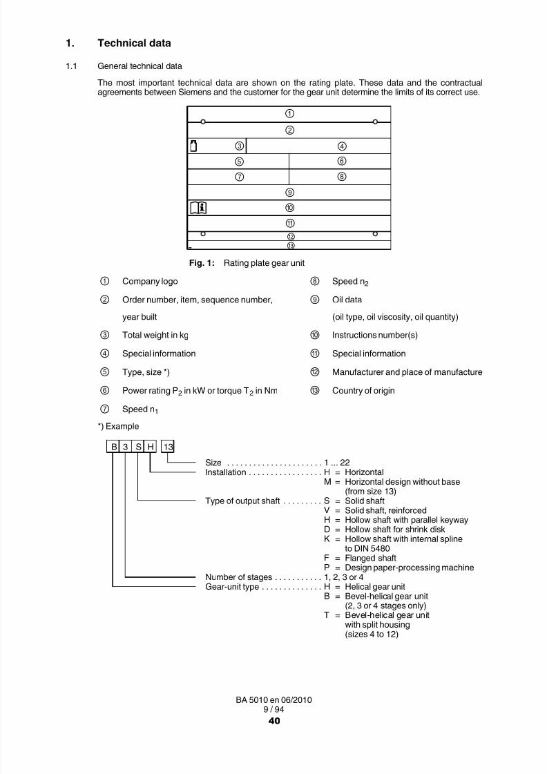
8/15/2019 r1_OF 71289_6 FF-AHF
http://slidepdf.com/reader/full/r1of-712896-ff-ahf 170/333
9 / 94BA 5010 en 06/2010
1. Technical data
1.1 General technical data
The most important technical data are shown on the rating plate. These data and the contractualagreements between Siemens and the customer for the gear unit determine the limits of its correct use.
①
②
③ ④
⑤ ⑥
⑦ ⑧
⑨
⑩
Fig. 1: Rating plate gear unit
① Company logo ⑧ Speed n 2
② Order number, item, sequence number, ⑨ Oil data
year built (oil type, oil viscosity, oil quantity)
③ Total weight in kg ⑩ Instructions number(s)
④ Special information Special information
⑤ Type, size *) Manufacturer and place of manufacture
⑥ Power rating P 2 in kW or torque T 2 in Nm Country of origin
⑦ Speed n 1
*) Example
B 3 S H 13
Size 1 ... 22. . . . . . . . . . . . . . . . . . . . . .Installation H = Horizontal. . . . . . . . . . . . . . . . .
M = Horizontal design without base(from size 13)
Type of output shaft S = Solid shaft. . . . . . . . .V = Solid shaft, reinforcedH = Hollow shaft with parallel keywayD = Hollow shaft for shrink diskK = Hollow shaft with internal spline
to DIN 5480F = Flanged shaftP = Design paper processing machine
Number of stages 1, 2, 3 or 4. . . . . . . . . . .Gear-unit type H = Helical gear unit. . . . . . . . . . . . . .
B = Bevel-helical gear unit(2, 3 or 4 stages only)
T = Bevel-helical gear unitwith split housing(sizes 4 to 12)
40

8/15/2019 r1_OF 71289_6 FF-AHF
http://slidepdf.com/reader/full/r1of-712896-ff-ahf 171/333
10 / 94BA 5010 en 06/2010
Data on weights and measuring-surface sound-pressure levels of the various gear types are given initems 1.2.2 and/or 1.2.3 .
For further technical data, refer to the drawings in the gear-unit documentation.
1.2 Configurations and weights
1.2.1 Types
H.FH
H.HHH.DHH.KHH.PH
B.FHT.FH
B.HHB.DHB.KHT.HHT.DKT.KH
H.FM B.FM
H.HMH.DMH.KM
B.HMB.DMB.KM
H.SHH.VHH.PH
B.SHB.VHT.SH
41

8/15/2019 r1_OF 71289_6 FF-AHF
http://slidepdf.com/reader/full/r1of-712896-ff-ahf 172/333
11 / 94BA 5010 en 06/2010
1.2.2 Weights
Table 1: Weights (approximate values)
TypeApprox. weight (kg) for size
1 2 3 4 5 6 7 8 9 10 11 12
H1SH 55 ‐ 128 302 547 862 1515
H2PH ‐ ‐ ‐ ‐ 340 ‐ 550 ‐ 860 ‐ 1360 ‐
H2.H ‐ ‐ 115 190 300 355 505 590 830 960 1335 1615
H2.M ‐ ‐
H3.H ‐ ‐ 320 365 540 625 875 1020 1400 1675
H3.M ‐ ‐
H4.H ‐ ‐ 550 645 875 1010 1460 1725
H4.M ‐ ‐
B2.H 50 82 140 235 360 410 615 700 1000 1155 1640 1910
B2.M‐ ‐
B3.H ‐ ‐ 130 210 325 380 550 635 890 1020 1455 1730
B3.M ‐ ‐
B4.H ‐ ‐ 335 385 555 655 890 1025 1485 1750
B4.M ‐ ‐
TypeApprox. weight (kg) for size
13 14 15 16 17 18 19 20 21 22
H1SH 2395 3200 4250 5800
H2PH ‐ ‐ ‐ ‐ ‐ ‐ ‐ ‐ ‐ ‐
H2.H 2000 2570 3430 3655 4650 5125 6600 7500 8900 9600
H2.M 1880 2430 3240 3465 4420 4870 6300 7200 8400 9200
H3.H 2295 2625 3475 3875 4560 5030 6700 8100 9100 9800
H3.M 2155 2490 3260 3625 4250 4740 6200 7600 8500 9300
H4.H 2390 2730 3635 3965 4680 5185 6800 8200 9200 9900
H4.M 2270 2600 3440 3740 4445 4915 6300 7700 8600 9400
B2.H 2450 2825 3990 4345 5620 6150
B2.M 2350 2725 3795 4160 5320 5860
B3.H 2380 2750 3730 3955 4990 5495 7000 8100 9200 9900
B3.M 2260 2615 3540 3765 4760 5240 6500 7600 8600 9400
B4.H 2395 2735 3630 3985 4695 5200 6800 8200 9200 9900
B4.M 2280 2605 3435 3765 4460 4930 6300 7700 8600 9400
All weights are for units without oil filling and add-on parts. For the exact weights, refer to thedrawings in the gear-unit documentation.
42

8/15/2019 r1_OF 71289_6 FF-AHF
http://slidepdf.com/reader/full/r1of-712896-ff-ahf 173/333

8/15/2019 r1_OF 71289_6 FF-AHF
http://slidepdf.com/reader/full/r1of-712896-ff-ahf 174/333
13 / 94BA 5010 en 06/2010
1.2.3 Measuring-surface sound-pressure level
The gear unit has a measuring-surface sound-pressure level at a distance of 1 m, which can be found intables 4 to 7.
The measurement is carried out to DIN EN ISO 9614 Part 2, using the sound-intensity method.
The workplace of the operating personnel is defined as the area on the measuring-surface at a distanceof 1 metre in the vicinity of which persons may be present.
The sound-pressure level applies to the warmed-up gear unit at input speed n 1 and output power P 2 statedon the rating plate, as measurement obtained on the Siemens test bench. If several figures are given, thehighest speed and power values apply.
The measuring-surface sound-pressure level includes add-on lubrication units, if applicable. Withoutgoing and incoming pipes, the interfaces are the flanges.
The sound-pressure levels stated in the table were obtained by statistical calculation by our Quality ControlDept. The gear unit can be statistically expected to comply with these sound-pressure levels.
1.2.3.1 Measuring-surface sound-pressure level for bevel-helical gear units (B...) with fan
Table 4: Measuring-surface sound-pressure level L pA in dB(A) for bevel-helical gear units with fan
Type iNn1
1/min
Gear-unit size
1 2 3 4 5 6 7 8 9 10 11 12 13 14 15 16 17 18 19 20 21 22
B2
5 1500 71 72 73 76 79 81 83 84 85 87 88 89 91 92 94
. 1000 66 66 67 71 73 74 77 78 79 80 82 83 84 85 87 89 90
8 750 1) 60 61 64 66 67 70 71 72 73 75 76 77 78 81 82 83 85
9 1500 68 69 70 73 75 76 78 81 82 83 84 85 86 87 88 90
. 1000 61 62 63 67 68 70 73 74 75 77 79 80 81 82 83 84 86 87
14 750 1) 60 1) 61 62 64 66 67 68 70 72 73 74 75 77 78 79 80
16 1500 65 66 67 71 74 76 78 79 80 81 83 84 87 88 89 90
. 1000 1) 1) 60 64 67 68 70 72 73 74 78 79 80 81 82 83 84 84
22.4 750 1) 1) 1) 1) 61 63 65 67 68 69 71 72 73 73 74 74 75 76
T3B3
12.5 1500 69 72 75 77 79 80 81 82 83 85 88 89 90 91 93 93 93 93 95 95
. 1000 62 65 68 69 71 72 73 74 77 78 80 82 83 83 84 85 86 86 88 88
31.5 750 1) 1) 63 64 66 68 69 70 71 73 74 75 76 77 78 78 79 79 81 81
35.5 1500 67 69 72 73 74 75 77 79 82 84 86 87 88 89 90 91 92 92 93 93
. 1000 1) 63 65 66 67 69 71 72 73 75 77 78 79 80 81 82 83 84 85 86
56 750 1) 1) 1) 1) 62 64 65 67 69 70 71 72 73 74 75 76 77 78 79 79
63 1500 66 68 70 71 73 74 76 78 81 83 85 86 87 88 89 90 91 91 92 92
. 1000 1) 61 63 64 66 68 69 71 73 75 77 78 79 80 81 81 82 82 83 84
90 750 1) 1) 1) 1) 61 63 64 66 67 68 70 71 72 73 74 75 75 76 77 77
1) LpA < 60 dB(A)
44
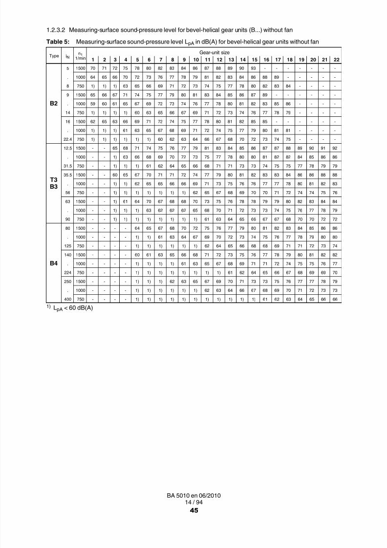
8/15/2019 r1_OF 71289_6 FF-AHF
http://slidepdf.com/reader/full/r1of-712896-ff-ahf 175/333
14 / 94BA 5010 en 06/2010
1.2.3.2 Measuring-surface sound-pressure level for bevel-helical gear units (B...) without fan
Table 5: Measuring-surface sound-pressure level L pA in dB(A) for bevel-helical gear units without fan
Type iNn1
1/minGear-unit size
1 2 3 4 5 6 7 8 9 10 11 12 13 14 15 16 17 18 19 20 21 22
B2
5 1500 70 71 72 75 78 80 82 83 84 86 87 88 89 90 93
. 1000 64 65 66 70 72 73 76 77 78 79 81 82 83 84 86 88 89
8 750 1) 1) 1) 63 65 66 69 71 72 73 74 75 77 78 80 82 83 84
9 1500 65 66 67 71 74 75 77 79 80 81 83 84 85 86 87 89
. 1000 59 60 61 65 67 69 72 73 74 76 77 78 80 81 82 83 85 86
14 750 1) 1) 1) 1) 60 63 65 66 67 69 71 72 73 74 76 77 78 79
16 1500 62 65 63 66 69 71 72 74 75 77 78 80 81 82 85 85
. 1000 1) 1) 1) 61 63 65 67 68 69 71 72 74 75 77 79 80 81 81
22.4 750 1) 1) 1) 1) 1) 1) 60 62 63 64 66 67 68 70 72 73 74 75
T3B3
12.5 1500 65 68 71 74 75 76 77 79 81 83 84 85 86 87 87 88 89 90 91 92
. 1000 1) 63 66 68 69 70 72 73 75 77 78 80 80 81 82 82 84 85 86 86
31.5 750 1) 1) 1) 61 62 64 65 66 68 71 71 73 73 74 75 75 77 78 79 79
35.5 1500 60 65 67 70 71 71 72 74 77 79 80 81 82 83 83 84 86 86 88 88
. 1000 1) 1) 62 65 65 66 66 69 71 73 75 76 76 77 77 78 80 81 82 83
56 750 1) 1) 1) 1) 1) 1) 1) 62 65 67 68 69 70 70 71 72 74 74 75 76
63 1500 1) 61 64 70 67 68 68 70 73 75 76 78 78 79 79 80 82 83 84 84
. 1000 1) 1) 1) 63 62 62 62 65 68 70 71 72 73 73 74 75 76 77 78 79
90 750 1) 1) 1) 1) 1) 1) 1) 1) 61 63 64 65 66 67 67 68 70 70 72 72
B4
80 1500 64 65 67 68 70 72 75 76 77 79 80 81 82 83 84 85 86 86
. 1000 1) 1) 61 63 64 67 69 70 72 73 74 75 76 77 78 79 80 80
125 750 1) 1) 1) 1) 1) 1) 62 64 65 66 68 68 69 71 71 72 73 74
140 1500 60 61 63 65 66 68 71 72 73 75 76 77 78 79 80 81 82 82
. 1000 1) 1) 1) 1) 61 63 65 67 68 69 71 71 72 74 75 75 76 77
224750 1) 1) 1) 1) 1) 1) 1) 1) 61 62 64 65 66 67 68 69 69 70
250 1500 1) 1) 1) 62 63 65 67 69 70 71 73 73 75 76 77 77 78 79
. 1000 1) 1) 1) 1) 1) 1) 62 63 64 66 67 68 69 70 71 72 73 73
400 750 1) 1) 1) 1) 1) 1) 1) 1) 1) 1) 1) 61 62 63 64 65 66 66
1) LpA < 60 dB(A)
45

8/15/2019 r1_OF 71289_6 FF-AHF
http://slidepdf.com/reader/full/r1of-712896-ff-ahf 176/333
15 / 94BA 5010 en 06/2010
1.2.3.3 Measuring-surface sound-pressure level for helical-gear units (H...) with fan
Table 6: Measuring-surface sound-pressure level L pA in dB(A) for helical-gear units with fan
Type iNn1
1/minGear-unit size
1 2 3 4 5 6 7 8 9 10 11 12 13 14 15 16 17 18 19 20 21 22
H1
1.25 1500 76 81 84 87 91
. 1000 71 76 79 81 83 85
2 750 67 72 75 78 80 82 85
2.24 1500 73 79 82 84 89 90
. 1000 68 74 77 79 82 84 87
3.55 750 64 70 72 75 78 80 83 84
4 1500 70 77 81 83 86 89 93
. 1000 65 71 75 77 80 82 84 85 87
5.6 750 61 68 71 72 75 77 79 81 83
H2
6.3 1500 75 76 77 80 81 82 84 85 86 88 90 92 94 96 96
. 1000 69 71 72 74 75 77 79 80 81 83 84 85 86 87 88 88 89 90
10 750 66 68 69 70 72 73 75 76 77 79 80 81 82 83 83 84 84 85 85
11.2 1500 73 75 77 79 80 81 82 85 88 90 91 92 93 95 95
. 1000 68 69 70 72 73 75 77 79 80 82 83 84 85 85 86 86 87 87 87
16 750 64 66 67 69 70 71 73 74 76 78 79 79 80 81 81 82 82 83 83
18 1500 71 73 75 77 78 80 82 84 86 87 90 91 92 93 94 94 95 95 95
. 1000 65 67 68 71 72 73 75 77 78 80 81 82 83 83 84 85 85 86 86
28 750 62 64 65 67 68 69 71 73 74 75 77 78 79 79 80 80 81 81 81
H3
22.4 1500 71 72 75 75 77 77 80 80 81 81 84 84 84 85
. 1000 65 66 69 70 71 72 74 75 75 75 78 78 78 79
35.5 750 62 62 66 67 67 68 70 70 71 72 74 74 75 76
40 1500 70 71 73 74 76 76 79 79 80 80 83 82 83 83
. 1000 64 65 67 68 69 70 73 73 73 74 77 77 77 77
63 750 62 62 63 64 65 66 69 69 69 70 72 73 73 73
71 1500 70 70 72 72 75 75 78 78 78 78 82 82 82 82
. 1000 64 64 65 66 68 69 71 72 72 72 75 75 75 76
112 750 61 61 62 62 64 65 67 67 68 68 71 71 71 72
46

8/15/2019 r1_OF 71289_6 FF-AHF
http://slidepdf.com/reader/full/r1of-712896-ff-ahf 177/333
16 / 94BA 5010 en 06/2010
1.2.3.4 Measuring-surface sound-pressure level for helical-gear units (H...) without fan
Table 7: Measuring-surface sound-pressure level L pA in dB(A) for helical-gear units without fan
Type iNn1
1/minGear-unit size
1 2 3 4 5 6 7 8 9 10 11 12 13 14 15 16 17 18 19 20 21 22
H1
1.25 1500 75 73 77 79 81 83
. 1000 70 69 72 75 76 78 80
2 750 66 65 69 71 73 75 77 79
2.24 1500 72 70 75 77 79 81 83. 1000 67 66 70 72 74 76 78 80
3.55 750 63 62 67 68 71 73 75 77 79
4 1500 69 67 72 74 76 78 79 82
. 1000 64 1) 67 70 71 73 75 77 79 81
5.6 750 60 1) 63 66 67 70 71 74 76 78
H2
6.3 1500 71 74 75 76 77 79 79 80 81 81 82 84 85 85 86
. 1000 66 69 70 71 72 74 74 75 76 76 77 80 80 80 81 83 83 84
10 750 63 66 67 67 69 70 71 72 73 73 74 76 77 77 78 80 80 81 81
11.2 1500 69 72 73 74 75 77 77 78 79 79 80 82 83 83 84
. 1000 64 67 68 69 70 72 72 73 74 74 75 77 78 78 79 81 81 82 82
16 750 61 64 65 66 67 69 69 70 71 71 72 74 75 75 76 77 78 79 79
18 1500 66 69 70 71 72 74 74 75 76 77 78 80 80 81 82 83 84 84 85. 1000 61 64 65 66 68 69 69 70 71 72 73 75 75 76 77 78 79 79 80
28 750 1) 61 62 63 64 66 66 67 68 69 70 72 72 73 73 75 75 76 76
H3
22.4 1500 68 69 73 74 74 75 77 77 78 79 81 81 82 83 83 84 85 86
. 1000 63 65 68 69 69 71 72 73 73 74 76 77 77 78 79 79 81 81
31.5 750 60 61 65 66 65 67 69 69 70 71 73 73 74 75 75 76 77 78
35.5 1500 65 67 70 71 71 73 74 75 76 76 78 79 79 80 81 81 83 83
. 1000 1) 62 65 66 66 68 69 70 71 72 73 74 75 75 76 77 78 78
63 750 1) 1) 62 63 63 65 66 67 67 68 70 71 71 72 73 73 75 75
71 1500 62 64 67 68 68 70 71 72 73 74 76 76 77 78 78 79 80 81
. 1000 1) 1) 62 63 63 65 66 67 68 69 71 71 72 73 73 74 75 76
112 750 1) 1) 1) 1) 1) 62 63 64 65 66 68 68 69 70 70 71 72 72
H4
100 1500 66 67 68 69 70 71 72 73 75 75 76 76 77 78 78 78. 1000 62 63 63 64 65 66 67 68 70 70 71 72 72 73 73 74
140 750 1) 1) 1) 61 62 63 64 64 66 67 68 68 69 69 70 70
160 1500 64 65 66 66 68 68 69 70 72 73 73 74 74 75 75 76
. 1000 1) 60 61 62 63 64 64 65 67 68 68 69 70 70 71 71
250 750 1) 1) 1) 1) 60 61 61 62 64 64 65 66 66 67 67 68
280 1500 61 62 63 64 65 66 67 67 69 70 70 71 72 72 73 73
. 1000 1) 1) 1) 1) 60 61 62 63 64 65 66 66 67 68 68 68
450 750 1) 1) 1) 1) 1) 1) 1) 1) 61 62 62 63 64 64 65 65
1) LpA < 60 dB(A)
47

8/15/2019 r1_OF 71289_6 FF-AHF
http://slidepdf.com/reader/full/r1of-712896-ff-ahf 178/333
17 / 94BA 5010 en 06/2010
2. General notes
2.1 Introduction
These instructions are an integral part of the gear unit supplied and must be kept in its vicinity for referenceat all times.
All persons carrying out work on the gear unit must have read and understood theseinstructions and must adhere to them. Siemens accepts no responsibility for damage
or disruption caused by disregard of these instructions.
The "FLENDER gear unit" dealt with in these instructions has been developed for driving machines ingeneral engineering applications. Possible applications for gear units of this series are the chemical,rubber, food processing, plastics and other industries.
The gear unit is designed only for the application specified in section 1, "Technical data". Other operatingconditions must be contractually agreed.
The gear unit has been manufactured in accordance with the state of the art and is delivered in a conditionfor safe and reliable use.
The gear unit must be used and operated strictly in accordance with the conditions laid down in the contractgoverning performance and supply agreed by Siemens and the customer.
The gear unit described in these instructions reflects the state of technical development at the time theseinstructions went to print.
In the interest of technical progress we reserve the right to make changes to the individual assemblies andaccessories which we regard as necessary to preserve their essential characteristics and improve theirefficiency and safety.
2.2 Copyright
The copyright to these instructions is held by Siemens AG .
These instructions must not be wholly or partly reproduced for competitive purposes, used in anyunauthorised way or made available to third parties without our agreement.
Technical enquiries should be addressed to the following works or to one of our customer services:Siemens Industriegetriebe GmbHThierbacher Straße 2409322 Penig
Tel.: +49 (0)37381 / 61 0Fax: +49 (0)37381 / 80286
48

8/15/2019 r1_OF 71289_6 FF-AHF
http://slidepdf.com/reader/full/r1of-712896-ff-ahf 179/333

8/15/2019 r1_OF 71289_6 FF-AHF
http://slidepdf.com/reader/full/r1of-712896-ff-ahf 180/333
19 / 94BA 5010 en 06/2010
When the gear unit is incorporated in plant or machinery, the manufacturer of suchplant or machinery must ensure that the contents of these instructions areincorporated in his own instructions.
• When removing the safety equipment the fixation means should be stored for later use. Removedsafety equipment must be re-installed prior to starting up.
• Notices attached to the gear unit, e.g. rating plate, direction arrows etc., must always be observed.They must be kept free from dirt and paint at all times. Missing plates must be replaced.
• Screws which have been damaged during assembly or disassembly work must be replaced with newones of the same strength class and type.
• Spare parts should always be obtained from Siemens (see also section 11).
3.2 Environmental protection
• Dispose of any packing material in accordance with regulations or separate it for recycling.
• When changing oil, the used oil must be collected in suitable containers. Any pools of oil which mayhave collected should be removed at once with an oil binding agent.
• Preservative agents should be stored separately from used oil.
• Used oil, preservative agents, oil-binding agents and oil-soaked cloths must be disposed of inaccordance with environmental legislation.
• Disposal of the gear unit after its useful life:
─ Drain all the operating oil, preservative agent and/or cooling agent from the gear unit and disposeof in accordance with regulations.
─ Depending on national regulations, gear-unit components and/or add-on parts may have to bedisposed of or sent for recycling separately.
3.3 Special dangers and personal protective equipment
• Depending on operating conditions, the surface of the gear unit may heat up or cool down to extremetemperatures.
In the case of hot surfaces (> 55 °C) there is a risk of burns!
In the case of cold surfaces (< 0 °C) there is a risk of frost injury (pain, numbness,frostbite)!
During oil changes there is a risk of scalding from escaping oil!
Small foreign matter such as sand, dust, etc. can get into the cover plates of therotating parts and be thrown back by these.Risk of eye injury!
In addition to any generally prescribed personal safety equipment (such as safety shoes,safety clothing, helmet) handling the gear unit requires wearing suitable safety gloves andsuitable safety glasses !
The gear unit is not suitable for operation in explosion hazard locations. It must underno circumstances be used in such locations because of the risk to life and limb.
50
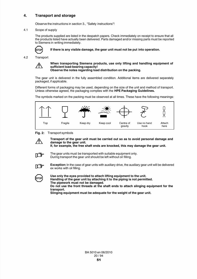
8/15/2019 r1_OF 71289_6 FF-AHF
http://slidepdf.com/reader/full/r1of-712896-ff-ahf 181/333
20 / 94BA 5010 en 06/2010
4. Transport and storage
Observe the instructions in section 3. , "Safety instructions"!
4.1 Scope of supply
The products supplied are listed in the despatch papers. Check immediately on receipt to ensure that allthe products listed have actually been delivered. Parts damaged and/or missing parts must be reportedto Siemens in writing immediately.
If there is any visible damage, the gear unit must not be put into operation.
4.2 Transport
When transporting Siemens products, use only lifting and handling equipment ofsufficient load-bearing capacity!Observe the notes regarding load distribution on the packing.
The gear unit is delivered in the fully assembled condition. Additional items are delivered separatelypackaged, if applicable.
Different forms of packaging may be used, depending on the size of the unit and method of transport.Unless otherwise agreed, the packaging complies with the HPE Packaging Guidelines.
The symbols marked on the packing must be observed at all times. These have the following meanings:
Top Fragile Keep dry Keep cool Centre ofgravity
Use no handhook
Attachhere
Fig. 2: Transport symbols
Transport of the gear unit must be carried out so as to avoid personal damage anddamage to the gear unit.If, for example, the free shaft ends are knocked, this may damage the gear unit.
The gear units must be transported with suitable equipment only.During transport the gear unit should be left without oil filling.
Exception: In the case of gear units with auxiliary drive, the auxiliary gear unit will be deliveredex works with oil filling.
Use only the eyes provided to attach lifting equipment to the unit.Handling of the gear unit by attaching it to the piping is not permitted.The pipework must not be damaged.
Do not use the front threads at the shaft ends to attach slinging equipment for thetransport.Slinging equipment must be adequate for the weight of the gear unit.
51

8/15/2019 r1_OF 71289_6 FF-AHF
http://slidepdf.com/reader/full/r1of-712896-ff-ahf 182/333
21 / 94BA 5010 en 06/2010
H... B...
Fig. 3: Attachment points on gear units types H... and B...
For drive units where add-on parts such as motor, add-on coupling etc. are mounted on the gear unit anadditional attachment point may be required because of the shift in the centre of gravity.
Units which are slung by eyebolts must not be tilted.
Fig. 4: Attachment points on gear units types H... with motor
Fig. 5: Attachment points on gear units types B... with motor
Fig. 6: Attachment points on gear units types B... with gear-unit swing base
52
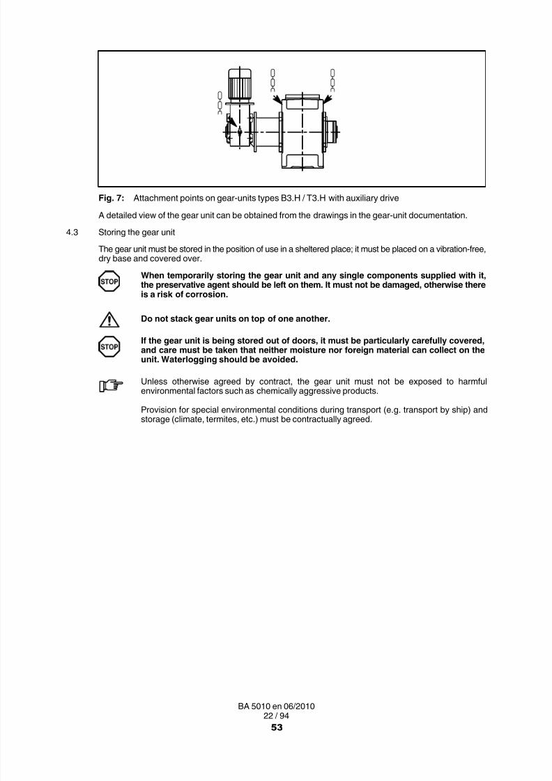
8/15/2019 r1_OF 71289_6 FF-AHF
http://slidepdf.com/reader/full/r1of-712896-ff-ahf 183/333
22 / 94BA 5010 en 06/2010
Fig. 7: Attachment points on gear-units types B3.H / T3.H with auxiliary drive
A detailed view of the gear unit can be obtained from the drawings in the gear unit documentation.
4.3 Storing the gear unit
The gear unit must be stored in the position of use in a sheltered place; it must be placed on a vibration-free,
dry base and covered over.When temporarily storing the gear unit and any single components supplied with it,the preservative agent should be left on them. It must not be damaged, otherwise thereis a risk of corrosion.
Do not stack gear units on top of one another.
If the gear unit is being stored out of doors, it must be particularly carefully covered,and care must be taken that neither moisture nor foreign material can collect on theunit. Waterlogging should be avoided.
Unless otherwise agreed by contract, the gear unit must not be exposed to harmful
environmental factors such as chemically aggressive products.
Provision for special environmental conditions during transport (e.g. transport by ship) andstorage (climate, termites, etc.) must be contractually agreed.
53

8/15/2019 r1_OF 71289_6 FF-AHF
http://slidepdf.com/reader/full/r1of-712896-ff-ahf 184/333
23 / 94BA 5010 en 06/2010
4.4 Standard coating and preservation
The gear unit is provided with an interior preservative agent; the free shaft ends are painted for protection.
The characteristics of the external coat depend on the ambient conditions stipulated in the order relatingto method of transport and area of application.
The gear unit is normally delivered completely ready, with a priming and a finish coat.
Where gear units are delivered with a priming coat only, it is necessary to apply a finishcoat in accordance with directives applying to the specific application.The priming coat alone is not suitable to provide a sufficient long-term corrosionprotection.
Ensure that the coat is not damaged!
Any damage may cause failure of the external protective coating and corrosion.
Unless otherwise contractually agreed, the interior preservation is guaranteed for 6 months,and the preservation of the free shaft ends for 24 months, provided that storage is in dry,frostfree sheds.
The guarantee period starts on the date of delivery or that of the notice that the item is ready
for shipment.
For longer periods of storage (> 6 months) we advise regular checking and, if necessary, renewal of theinterior and exterior preservation (see section 7, "Start-up").
The output shaft must then be rotated at least one turn to change the position of the rolling element in thebearings. The input shaft must not be in the same position as before rotation.
This procedure must be repeated and documented every 6 months until start-up.
54

8/15/2019 r1_OF 71289_6 FF-AHF
http://slidepdf.com/reader/full/r1of-712896-ff-ahf 185/333
24 / 94BA 5010 en 06/2010
4.4.1 Interior preservation with preservative agent
Table 8: Durability period and measures for interior preservation when using mineral oil or PAO-basedsynthetic oil
Duration of protection Preservative agent Special measures
up to 6 months
Castrol Alpha SP 220 S
none
up to 24 months
Close all holes in the gear unit- Replace air filter or breather screw
with screw plug.(replace screw plug with air filter orbreather screw before start-up)
For storage periods longer than 24 months, renew the preservative agent.For storage periods longer than 36 months, Siemens should be consulted before.
Table 9: Durability period and measures for interior preservation when using PG-based synthetic oil
Duration of protection Preservative agent Special measures
up to 6 months
Special anti-corrosion oilTRIBOL 1390 1)
none
up to 36 months
Close all holes in the gear unit- Replace air filter or breather screw
with screw plug.(replace screw plug with air filter orbreather screw before start-up)
For storage periods longer than 36 months, Siemens should be consulted before.1) Resistant to tropical conditions and sea water; max. ambient temperature 50 °C
4.4.2 Exterior preservation
Table 10: Durability period for exterior preservation of shaft ends and other bright machined surfaces
Durationof protection Preservativeagent Layerthickness Remarks
in caseof indoor storage
up to 36 months 1)Tectyl 846 K19 approx. 50 µm
Long-term wax-based preservativeagent:
resistant to seawater- resistant to tropical conditions- (soluble with CH compounds)
in caseof outdoor storageup to 12 months 2)
1) The gear unit must be stored in the position of use in a sheltered place; it must be placed ona vibration-free, dry wooden base and covered over.
2) If the gear unit is being stored out of doors, it must be particularly carefully covered, and care must betaken that neither moisture nor foreign material can collect on the unit. Waterlogging should be avoided.
The procedure for interior and exterior preservation treatment is described in section 7(see items 7.3.1.3 and 7.3.2.1)!
55

8/15/2019 r1_OF 71289_6 FF-AHF
http://slidepdf.com/reader/full/r1of-712896-ff-ahf 186/333
25 / 94BA 5010 en 06/2010
5. Technical description
Observe the instructions in section 3. "Safety instructions"!
5.1 General description
The helical gear unit is supplied as a one-, two-, three- or four-stage gear unit. The bevel-helical gear unitis supplied as a two-, three- or four-stage gear unit. The gear unit may also be supplied as a multi-stagebevel-helical gear unit or helical gear unit with fitted auxiliary drive. It is designed for installation in the
horizontal mounting position. If necessary, it can also be designed for installation in a different position.As a principle, the gear unit can be operated in both directions of rotation. The onlyexceptions are gear types with backstop or overrunning clutch. If rotation reversal isrequired for these types of unit, Siemens should be consulted.
A number of shaft configurations (types and rotation directions) are possible. These are shown in thefollowing table as solid shafts:
Table 11: Types and rotation directions
TypeType
A B C D E F G H I
H1SH
H2SH H2HMH2HH H2DMH2DH H2KMH2KH H2FMH2FH H2VHH2PH
H3SH H3HMH3HH H3DMH3DH H3KMH3KH H3FM
H3FH H3VHH4SH H4HMH4HH H4DMH4DH H4KMH4KH H4FMH4FH H4VH
B2SH B2HMB2HH B2DMB2DH B2KMB2KH B2FMB2FH B2VH
B3SH B3HMB3HH B3DMB3DH B3KM
B3KH B3FMB3FH B3VHT3SH T3VHT3DH T3HHT3KH T3FH
56

8/15/2019 r1_OF 71289_6 FF-AHF
http://slidepdf.com/reader/full/r1of-712896-ff-ahf 187/333
26 / 94BA 5010 en 06/2010
TypeType
Type IHGFEDCBAB4SH B4HMB4HH B4DMB4DH B4KMB4KH B4FMB4FH B4VH
When mounting the auxiliary drive (as maintenance and/or load drive) the assignment of thedirection of rotation to the design is defined in the dimensioned drawing.
The gear units are characterised by a low noise level. This is achieved by helical and bevel-helical gearswith a high contact ratio and special sound-damping housings.The good temperature characteristics of the gear unit are achieved by its high degree of efficiency, largehousing surface and performance-related cooling system.
5.2 Output designs
..S. ..V. ..F. ..H. ..D. ..K.Solid shaft Solid shaft, Flanged shaft Hollow shaft Hollow shaft Hollow shaft with
reinforced with for internal splineparallel keyway shrink disk to DIN 5480
Fig. 8: Output designs
5.3 Housing
The housing is of cast iron; if required, they may also be of steel.
Housings up to size 12 are made in one part. The exception are types H1SH and H2PH, which havea two-part housing similar to those of sizes 13 to 22 of the other types. The housing is rigid in design anddue to its form has excellent noise and temperature characteristics.
The gear-unit housing comes with the following equipment:
• Lifting eyes (adequately dimensioned for transport)
• Inspection and/or assembly cover (for oil filling and/or inspection)
• Oil sight glass or oil dipstick (to check the oil level)
• Oil drain plug (for oil drain)
• Air filter or venting screw (for aeration and ventilation)
Colour codes for ventilating, oil inlet, oil level and oil drainage:
Air relief point: yellow Oil-draining point: white
Oil-filling point: yellow Lubrication point: red
Oil level: red Oil level: red
57

8/15/2019 r1_OF 71289_6 FF-AHF
http://slidepdf.com/reader/full/r1of-712896-ff-ahf 188/333
27 / 94BA 5010 en 06/2010
8
7
10
11
6
2 3 1414
13
5
912
17
5
7 1)
18
Fig. 9: Gear-unit features on gear units type H..H ≤ 12
1) for H1SH only
43 14 1
6
7
10
8
5
13
5
9
1112
3 15
16
17
2
Fig. 10: Gear-unit features on gear units type H..H ≥ 13
43 14 1
6
7
10
8
5
13
5
9
18 12
3 15
17
2
Fig. 11: Gear-unit features on gear units type H..M ≥ 13
58

8/15/2019 r1_OF 71289_6 FF-AHF
http://slidepdf.com/reader/full/r1of-712896-ff-ahf 189/333
28 / 94BA 5010 en 06/2010
8
7
10
6
2 3 1414
9
5
13
12
17
18
5
11
Fig. 12: Gear-unit features on gear units types B..H and T..H ≤ 12
6
7
10
8
5 5
11
12
13
9
16
43 14 13 1517
2
Fig. 13: Gear-unit features on gear units type B..H ≥ 13
6
7
10
8
5 5
18
12
13
9
43 14 13 1517
2
Fig. 14: Gear-unit features on gear units type B..M ≥ 13
1 Housing 10 Rating plate2 Lifting eyes 11 Gear-unit fastening3 Cover 12 Fan cowl4 Cover 13 Fan5 Shaft seals 14 Inspection and/or assembly cover6 Oil dipstick 15 Alignment surfaces7 Housing ventilation 16 Alignment thread8 Oil drain plug 17 Oil inlet9 Cover and/or bearing journal 18 Fastening for torque arm
59
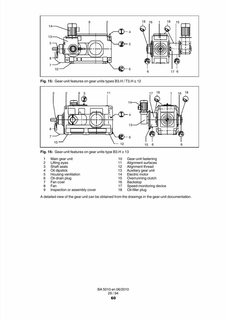
8/15/2019 r1_OF 71289_6 FF-AHF
http://slidepdf.com/reader/full/r1of-712896-ff-ahf 190/333

8/15/2019 r1_OF 71289_6 FF-AHF
http://slidepdf.com/reader/full/r1of-712896-ff-ahf 191/333
30 / 94BA 5010 en 06/2010
5.4 Toothed components
The externally toothed components of the gear unit are case-hardened. Helical-gear teeth are ground. Thehigh quality of the teeth leads to a significant noise reduction and ensures safe and reliable running.
The gears are connected with the shafts by interference fits and parallel keys or by shrink fits. These typesof joints transmit with adequate reliability the torques generated.
5.5 Lubrication
5.5.1 Splash lubricationUnless otherwise agreed in the order, the teeth and bearings are adequately splash-lubricated with oil. Thegear unit thus requires very little maintenance.
5.5.2 Pressure lubrication through add-on oil-supply system
In non-horizontal positions, with high bearing speeds or peripheral velocities on the teeth, the splashlubrication system may be supported and/or replaced with a pressure lubrication system.
The oil-supply system is permanently attached to the gear unit and consists of a flange pump, a coarsefilter, a pressure-monitoring device and pipework. For gear units of sizes 13 to 22, the coarse filter isreplaced with a double change-over filter.
The direction of flow from the flange pumps is independent of the direction of rotation .
1
23
1
2
4
H... ≤ 12 H... ≥ 13
Fig. 17: Add-on oil-supply system on gear units type H...
1
23
1
24
B... ≤ 12 B... ≥ 13
Fig. 18: Add-on oil-supply system on gear units type B...
1 Flange pump 3 Coarse filter2 Pressure monitor 4 Double change-over filter
A detailed view of the gear unit can be obtained from the drawings in the gear-unit documentation.
61

8/15/2019 r1_OF 71289_6 FF-AHF
http://slidepdf.com/reader/full/r1of-712896-ff-ahf 192/333
31 / 94BA 5010 en 06/2010
In the case of gear units with add-onoil-supply system, before starting the unitup the pressure monitor must always beconnected so as to be ready for operation.
Depending on the order specification and application, theflange pump may be replaced with a motor pump.
When operating and servicing the components of the oil-supply system, observe the operatinginstructions of the components.For technical data, refer to the data sheet and/or the list of equipment.
5.6 Shaft bearings
All shafts are mounted in rolling bearings.
5.7 Shaft seals
Depending on requirements, radial shaft sealing rings, labyrinth seals, or Taconite seals or Tacolab sealsare mounted at the shaft exits to prevent oil from leaking from the housing and dirt from entering it.
5.7.1 Radial shaft-sealing rings
Radial shaft-sealing rings are the standard type of seal. They are fitted preferably with an additional dustlip to protect the actual sealing lip from external contamination.
Use in an area with much dust is not possible.
Fig. 19: Radial shaft-sealing ring
5.7.2 Labyrinth seals
Labyrinth seals are non-contacting and avoid wear to the shaft. They therefore require no maintenanceand ensure favourable temperature characteristics. They can be used only with certain transmission ratiosand minimum speeds.
Check in the spare parts drawing and the spare parts list whether the gear unit is provided with labyrinthseals.
Fig. 20: Labyrinth seal
For reliable operation, this type of seal requires stationary, horizontal positioning ina splash-free and relatively dust-free environment. Overfilling of the gear unit cancause leakage, as can oil with high foam content.
To be connectedas opener or closer,as required.
0.5 bar
62

8/15/2019 r1_OF 71289_6 FF-AHF
http://slidepdf.com/reader/full/r1of-712896-ff-ahf 193/333
32 / 94BA 5010 en 06/2010
5.7.3 Taconite seals
Taconite seals were specially developed for use in a dusty environment. The penetration of dust isprevented by a combination of three seal elements (radial shaft-sealing ring, lamellar seal andgrease-charged labyrinth seal).
1
2
3
4
Fig. 21: Taconite seal
1 Radial shaft-sealing ring 3 Grease-charged labyrinth seal (re-chargeable)2 Lamellar seal 4 Flat grease nipple AM10x1 to DIN 3404
Taconite seals are divided into the following types:
1
2
3
14
Taconite "F‐F" and "F‐H" Taconite "F‐K"
Taconite "E" Taconite "F"
Fig. 22: Taconite seal, variants E, F, F-F, F-H and F-K
1 Output 3 Taconite "F-H"2 Taconite "F-F" 4 Taconite "F-K"
63

8/15/2019 r1_OF 71289_6 FF-AHF
http://slidepdf.com/reader/full/r1of-712896-ff-ahf 194/333
33 / 94BA 5010 en 06/2010
Table 12: Variant description Taconite seal
Taconitetype variant Application Remarks
"E" All input shaftswith or without fan
Re-chargeable labyrinth"F"
Output shaftType S (Solid shaft)Type V (Solid shaft, reinforced)Type F (Flanged shaft)
"F‐F"Output shaftType H (Hollow shaft with parallel keyway)Type K (Hollow shaft with internal spline
to DIN 5480)
Labyrinth re-chargeable on both sides,incl. dustproof cowl to prevent contacton gear side facing away from output
"F‐H"Output shaftType H (Hollow shaft with parallel keyway)Type K (Hollow shaft with internal spline
to DIN 5480 Labyrinth re-chargeable on output side;dustproof cowl on opposite side
"F‐K" Output shaftType D (Hollow shaft for shrink disk)
The specified frequencies must be observed (see section 10, "Maintenance andrepair") for re-charging the labyrinth seals with grease.
5.7.4 Tacolab seal
Tacolab seals are non-contacting seals, operating wearfreely and requiring very little maintenance andwhich thus do not cause operating interruptions.
The Tacolab seal is made up of two parts:
─ an oil labyrinth preventing lubricating oil from escaping,
─ dust seal filled with grease, which permits the use in very dusty environments.
45
1
3
2
Fig. 23: Tacolab seal
1 Labyrinth sealing ring 4 Grease-charged labyrinth seal (re-chargeable)
2 Labyrinth sealing ring 5 Flat grease nipple AM10x1 to DIN 34043 Lamellar seal
64
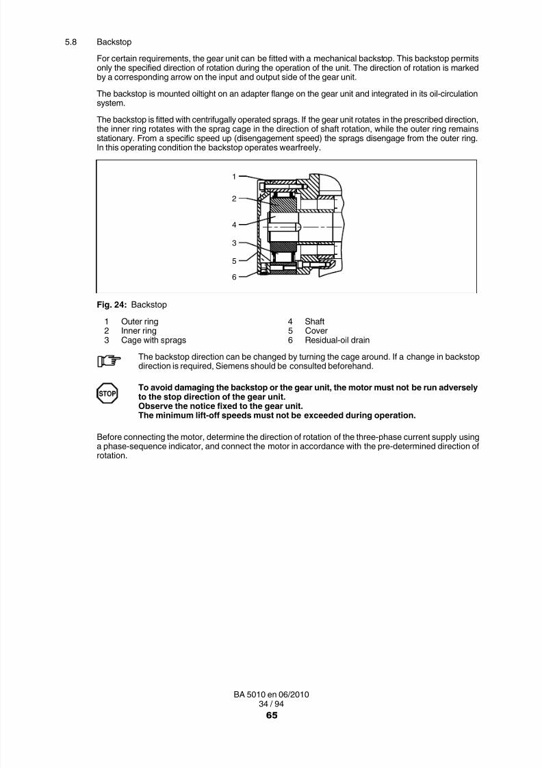
8/15/2019 r1_OF 71289_6 FF-AHF
http://slidepdf.com/reader/full/r1of-712896-ff-ahf 195/333
34 / 94BA 5010 en 06/2010
5.8 Backstop
For certain requirements, the gear unit can be fitted with a mechanical backstop. This backstop permitsonly the specified direction of rotation during the operation of the unit. The direction of rotation is markedby a corresponding arrow on the input and output side of the gear unit.
The backstop is mounted oiltight on an adapter flange on the gear unit and integrated in its oil-circulationsystem.
The backstop is fitted with centrifugally operated sprags. If the gear unit rotates in the prescribed direction,the inner ring rotates with the sprag cage in the direction of shaft rotation, while the outer ring remainsstationary. From a specific speed up (disengagement speed) the sprags disengage from the outer ring.In this operating condition the backstop operates wearfreely.
6
5
3
4
2
1
Fig. 24: Backstop
1 Outer ring 4 Shaft2 Inner ring 5 Cover3 Cage with sprags 6 Residual-oil drain
The backstop direction can be changed by turning the cage around. If a change in backstopdirection is required, Siemens should be consulted beforehand.
To avoid damaging the backstop or the gear unit, the motor must not be run adverselyto the stop direction of the gear unit.Observe the notice fixed to the gear unit.The minimum lift-off speeds must not be exceeded during operation.
Before connecting the motor, determine the direction of rotation of the three-phase current supply usinga phase-sequence indicator, and connect the motor in accordance with the pre-determined direction ofrotation.
65

8/15/2019 r1_OF 71289_6 FF-AHF
http://slidepdf.com/reader/full/r1of-712896-ff-ahf 196/333
35 / 94BA 5010 en 06/2010
5.9 Torque-limiting backstop (special design)
A torque-limiting backstop is available for special uses, e.g. dual drives. The backstop is a combinationof a backstop with centrifugally operated sprags and a brake. The slipping torque is set by a number ofcompression springs.
This "slipping" will protect the gear unit and the sprags of the backstop from inadmissibly high stressesduring negative rotation. In addition, a uniform load distribution onto both gear units is achieved duringnegative rotation when using dual drives.
1
3
7
2
xmin.
4
56
Fig. 25: Torque-limiting backstop
1 Outer ring 5 Locking wire2 Inner ring 6 Lead screw with compression spring3 Cage with sprags 7 Friction lining4 Shaft (adapter flange)
The torque-limiting backstop is attached to the gear unit by means of an adapter flange to form an oiltightseal and is integrated in its oil circulation system.
The stop direction can be changed by turning the cage around. If a change in stop direction isrequired, Siemens should be consulted beforehand.
The slipping torque was set at the correct value at the Siemens works; resetting during startupis not permissible.To safeguard the set slipping torque, the lead screws of the compression springs are securedwith locking wire. The warranty will expire if the locking wire for the screws is missing or hasbeen damaged.
For safety reasons, it is absolutely prohibited to change the slipping torque.After having stopped the motor, there is a danger that the load is not safely held in itsposition and can run in reverse direction at high speed.
As a rule, the backstop operates without wear. As a precaution, the dimension "x min. " must bechecked once yearly and after every releasing operation (Type FXRT only).
To avoid damaging the backstop or the gear unit, the motor must not be run adverselyto the stop direction of the gear unit.Observe the notice fixed to the gear unit.
66

8/15/2019 r1_OF 71289_6 FF-AHF
http://slidepdf.com/reader/full/r1of-712896-ff-ahf 197/333
36 / 94BA 5010 en 06/2010
5.10 Cooling
Depending on requirements, the gear unit is fitted with a fan, a cooling coil, an added-on oil-supply systemwith oil cooler or a separately provided oil-supply system. In the case of a separate oil-supply system, thespecific instructions for this oil-supply system must be observed.
When installing the gear unit free convection must be ensured on the housing surface, in orderto definitely avoid overheating the gear unit.
5.10.1 FanAs a rule the fan is mounted on the high-speed shaft of the gear unit and is protected from accidentalcontact by an air guide cover. The fan sucks air through the grid of the air guide cover and blows it alongthe air ducts on the side of the gear housing. It thereby dissipates a certain amount of heat from the housing.
2 2
1 1
H... B.../ T...
Fig. 26: Fan on gear units types H..., B... and T...
1 Fan 2 Air guide cover
A detailed view of the gear unit can be obtained from the drawings in the gear-unit documentation.
For gear units fitted with a fan, sufficient space must be allowed for air intake whenmounting the safety guards for the coupling or other components.The correct distance is given in the dimensioned drawing in the gear-unitdocumentation.It must be ensured that the fan cowl is correctly fastened. The fan cowl must beprotected against damage from outside. The fan must not come into contact with thefan cowl.
The cooling effect is considerably reduced if the fan or the gear housing are dirty(see section 10, "Maintenance and repair").
67

8/15/2019 r1_OF 71289_6 FF-AHF
http://slidepdf.com/reader/full/r1of-712896-ff-ahf 198/333
37 / 94BA 5010 en 06/2010
5.10.2 Cooling coil
The gear unit can be fitted with a cooling coil in the oil sump. Cooling water is supplied by way of a waterconnection. The operator must ensure this. Either fresh water, sea water or brackish water can be usedfor cooling purposes.
When water is flowing through the cooling coil, a certain amount of heat is transferred from the oil to thewater and thereby removed from the system.
1, 2
3
33
X
X
X
21
H... B...
Fig. 27: Cooling coil on gear units types H... and B...
1 Cooling-water connection 2 Reducing screw 3 Output shaft
A detailed view of the gear unit can be obtained from the drawings in the gear-unit documentation.
The water can flow through the gear unit in either direction. The pressure of the coolingwater must not exceed 8 bar.If the gear unit is being withdrawn from service for a longer period and if there isa danger of freezing, the cooling water must be drained off. Remove any remainingwater with compressed air.The ends of the cooling coil must never be twisted because this could destroy thecooling coil.The reducing bolt must not be tightened or demounted because this may result indamage to the cooling coil.
Be especially careful when blowing with compressed air.Wear protective glasses!
Avoid too high pressure on the cooling-water entry. For this a cooling-water flow control mustbe used (e.g. a pressure reducer or a suitable valve).
For connecting dimensions, refer to the dimensioned drawing of the gear unit. The requiredcooling water quantity and the max. permissible inlet temperature are given on the data sheetand/or the list of equipment.
68

8/15/2019 r1_OF 71289_6 FF-AHF
http://slidepdf.com/reader/full/r1of-712896-ff-ahf 199/333
38 / 94BA 5010 en 06/2010
Table 13: Cooling-water quantity required (l/min)
Type 3 4 5 6 7 8 9 10 11 12 13 14 15 16 17 18 19 20 to 22
H1SH 4 4 4 8 8 8 8 8 1)
H2.H 4 4 4 4 4 8 8 8 8 8 8 8 8 8 8 1) 1)
H2.M 8 8 8 8 8 81) 1)
H3.H 4 4 4 4 4 4 8 8 8 8 8 8 8 8 1) 1)
H3.M 8 8 8 8 8 81) 1)
B2.H 4 8 4 8 4 8 8 8 8 8 8 8 8 8 8
B3.H 4 4 4 4 4 8 8 8 8 8 8 8 8 8 8 1) 1)
B2.M 8 8 8 8 8 8
B3.M 8 8 8 8 8 81) 1)
1) on request
Refer to the order-specific dimensioned drawing for connecting dimensions.
5.10.3 Add-on oil-supply system with air oil-cooler
For types H1.., H2.. and B2.., an oil-supply system with air oil-cooler may be applied. This oil-coolingsystem is permanently attached to the gear unit.
Components:
• air oil-cooler
• flange pump
• coarse filter (double change-over filter from size 13)
• pressure-monitoring device
• temperature-control valve
• pipework
The air oil-cooler is designed to cool the gear oil by means of air from the surrounding atmosphere.Depending on the volume flow, the oil passes through the cooler in one or more streams and through thecurrent of air blown in by the fan. For cold starts, a bypass pipe with a temperature-control valve is providedfor.
The flow direction of the pump used is independent of the direction of rotation , if nothingis specified in the documentation to the contrary.When connecting the fittings the actual flow direction must however be observed.
69

8/15/2019 r1_OF 71289_6 FF-AHF
http://slidepdf.com/reader/full/r1of-712896-ff-ahf 200/333
39 / 94BA 5010 en 06/2010
H1.. / H2.. ≤ 12 H1.. / H2.. ≥ 13
5
1
2
6
1
2
6
5
3 4
Fig. 28: Air oil-cooling system on gear units types H1.. and H2..
B2.. ≤ 12 B2.. ≥ 13
5
1
2
6
1
2
6
5
3 4
Fig. 29: Air oil-cooling system on gear units types B1.. and B2..
1 Flange pump 4 Double change-over filter2 Pressure monitor (circuit diagram see item 5.5.2 ) 5 Air oil-cooler3 Coarse filter 6 Temperature-control valve
A detailed view of the gear unit can be obtained from the drawings in the gear-unit documentation.
When installing gear units with add-on air oil-cooling units, it must be ensured that theair circulation is not obstructed.The required minimum distance from adjacent components, walls, etc. is indicated inthe drawings in the unit documentation.Add-on pressure monitors must be connected as shown in item 5.5.2.
Depending on the application, the flange pump may have been replaced with a motor pump.
When operating and servicing the components of the oil-supply system, observe the operatinginstructions of the components.For technical data, refer to the data sheet and/or the list of equipment.
The cooling effect is considerably reduced if the cooler or the gear housing are dirty (see section 10. ,"Maintenance and repair").
70

8/15/2019 r1_OF 71289_6 FF-AHF
http://slidepdf.com/reader/full/r1of-712896-ff-ahf 201/333
40 / 94BA 5010 en 06/2010
5.10.4 Add-on oil-supply unit with water oil-cooler
For types H1.., H2.. and B2.., an oil-supply system with water oil-cooler may be applied, if required in theorder. This is permanently attached to the gear unit.
Components:
• pump
• water oil-cooler
• pipework
Depending on size and/or order-specification the oil-supply unit with water oil-cooler may in additioninclude the following components:
• filter
• monitoring equipment
The flow direction of the pump used is independent of the direction of rotation , if nothingis specified in the documentation to the contrary.When connecting the fittings the actual flow direction must however be observed.
The required water connection must be provided by the user.
H1.. / H2.. ≤ 12 H1.. / H2.. ≥ 13
5
16
3
4
1
2
6
5
2
Fig. 30: Water oil-cooling system on gear units types H1.. and H2..
B2.. ≤ 12 B2.. ≥ 13
5
1
2
6
3
4
16
5
2
Fig. 31: Water oil-cooling system on gear units type B2..
1 Flange pump 4 Double change-over filter2 Pressure monitor (circuit diagram see item 5.5.2 ) 5 Water oil-cooler3 Coarse filter 6 Water inlet and outlet
A detailed view of the gear unit can be obtained from the drawings in the gear-unit documentation.
71

8/15/2019 r1_OF 71289_6 FF-AHF
http://slidepdf.com/reader/full/r1of-712896-ff-ahf 202/333

8/15/2019 r1_OF 71289_6 FF-AHF
http://slidepdf.com/reader/full/r1of-712896-ff-ahf 203/333
42 / 94BA 5010 en 06/2010
H... / B... / T3.. ≤ 12 H... / B... ≥ 13
2 1 2 1 2 1 21
Fig. 32: Heating on gear units types H..., B... and T3..
1 Heating element 2 Temperature monitor
For a detailed illustration of the gear unit and the position of the add-on parts, refer to the drawings in thegear-unit documentation.
Never switch the heating elements on, unless complete immersion of the heating rodin the oil bath is ensured. Fire hazard!If heating elements are installed afterwards the max. heating capacity (see table 14)on the outer surface of the heating element must not be exceeded.
Table 14: Specific heating output P Hoas a function of the ambient termperature
PHo(W/cm²)
Ambient temperature°C
0.9
0.8
0.7
+ 10 to 0
0 to 25
25 to 50
Operation and maintenance must be in accordance with the pertinent operating instructions.For technical data, refer to the list of equipment.
5.12 Oil-temperature monitoring
Depending on the order specification, the gear unit may be fitted with a Pt 100 resistance thermometer formonitoring the oil temperature in the sump. In order to measure the temperatures or temperaturedifferences, the Pt 100 resistance thermometer should be connected to a suitable instrument provided bythe customer. The thermometer has a connection head (protection type IP 54) for the wiring.A two-conductor circuit is provided by the manufacturer. However, the customer may fit his own three- orfour-conductor circuit if required.
For control information, refer to the list of equipment.Observe the operating instructions relating to the device in all instances.
73

8/15/2019 r1_OF 71289_6 FF-AHF
http://slidepdf.com/reader/full/r1of-712896-ff-ahf 204/333
43 / 94BA 5010 en 06/2010
H... / B... / T3.. ≤ 12 H... / B... ≥ 13
1 1 1 1
Fig. 33: Oil-temperature measurement on gear units types H..., B... and T3..
1 Pt 100 resistance thermometer
For a detailed illustration of the gear unit and the position of the add-on parts, refer to the drawings in thegear-unit documentation.
When operating and servicing the components, observe the operating instructions relating tothe components.For technical data, refer to the data sheet and/or the list of equipment.
5.13 Oil-level monitoring system
Depending on the order specification, the gear unit can be fitted with an oil-level monitor in the form ofa level limit switch. This monitoring is designed as a standstill monitoring (gear unit stop) and checks thelevel of the oil before the unit is started up. When the signal "oil level too low" is given, it should be wiredin such a way that the drive motor cannot start and an alarm is given. During operation, any signal shouldbe bridged.
If an the oil-level monitoring device is in use, it is very important that the unit is in a horizontal position.
H... / B... / T3.. ≤ 12 H... / B... ≥ 13
Fig. 34: Oil-level monitoring on gear units types H..., B... and T3..For a detailed illustration of the gear unit and the position of the add-on parts, refer to the drawings in thegear-unit documentation.
When operating and servicing the components, observe the operating instructions relating tothe components.For technical data, refer to the data sheet and/or the list of equipment.
74

8/15/2019 r1_OF 71289_6 FF-AHF
http://slidepdf.com/reader/full/r1of-712896-ff-ahf 205/333
44 / 94BA 5010 en 06/2010
5.14 Bearing-monitoring system
The gear unit may be fitted with measuring nipples for monitoring the bearings. These nipples are intendedfor attachment of shock-pulse sensors with rapid-action coupling and are located in the vicinity of thebearings to be monitored.The gear unit may also be set up for temperature monitoring at the bearing points. The gear unit is thenequipped with tapped holes for fitting Pt 100 resistance thermometers. For this version Siemens must beconsulted.
H... Measuring nipple
XX
SW17
"X"
Fig. 35: Bearing monitoring on gear units type H...
B... Measuring nipple
XX
SW17
"X"X
Fig. 36: Bearing monitoring on gear units types B... and T3..
For a detailed illustration of the gear unit and the position of the add-on parts, refer to the drawings in thegear-unit documentation.
5.15 Speed transmitter
An incremental speed transmitter may be mounted. Wiring and evaluation instrument should be providedby the customer.
A"A"
2 1 3
1
3
Fig. 37: Speed monitoring device
1 Incremental transmitter 2 12-pole brass plug 3 Output
When operating and servicing the components, observe the operating instructions relating to
the components.For technical data, refer to the data sheet and/or the list of equipment.
A detailed view of the gear unit can be obtained from the drawings in the gear-unit documentation.
75

8/15/2019 r1_OF 71289_6 FF-AHF
http://slidepdf.com/reader/full/r1of-712896-ff-ahf 206/333
45 / 94BA 5010 en 06/2010
5.16 Auxiliary drive
For certain applications the gear unit can, in addition to the main drive unit, be equipped with an auxiliarydrive unit. This enables the main gear unit to be operated at a lower output speed in the same direction ofrotation. The auxiliary drive is connected with the main gear unit by an overrunning clutch. For the basicdrive arrangement, see figure 38.
Basic design of the gear unit with main and auxiliary drives
8
6 / 7
5
2
4
3
1
8
6
3
1
4
7
5
2
Fig. 38: Design of the gear unit with main and auxiliary drives
1 Main motor 4 Main gear unit 7 Overrunning clutch2 Auxiliary motor 5 Auxiliary gear unit 8 Output shaft of the main3 Coupling 6 Backstop gear unit
Depending on use, two auxiliary drives of different capacities are available for each gear-unit size.
5.16.1 Auxiliary drive, designed as a maintenance drive
The auxiliary drive should be protected from overloads.The drive of the bucket elevator via the auxiliary drive must only be effected during idlerunning, i.e. without load.
For the exact designation of the geared motor as well as the mounting position, refer to the drawings (seesection 1, "Technical Data"). The auxiliary gear unit has its own oil circulation system which is separatedfrom that of the main gear unit. The auxiliary gear unit is already filled with oil when delivered.
Before connecting the motor, determine the direction of rotation of the three-phasecurrent supply using a phase-sequence indicator, and connect the motor inaccordance with the pre-determined direction of rotation.Observe the notice fixed to the gear unit.
The Special operating instructions should be observed for operation of the auxiliary gear unit(Type KF MOTOX bevel-gear motor).
To avoid overspeeds in case of malfunctions of the overrunning clutch, the drive combination must be
equipped with a speed-monitoring device by the customer for safety reasons. The speed-monitoringdevice consists of a pulse generator mounted in the intermediate flange (figure 39 ) and of an evaluatinginstrument.
A threaded hole M12x1 for the pulse generator to be made available by the customer isprovided at a suitable position in the intermediate flange. The dimension " x" depends on theinstructions given by the equipment manufacturer (see figure 39 ). The pulse generator mustsatisfy the requirement "suitable for flush mounting" .
76
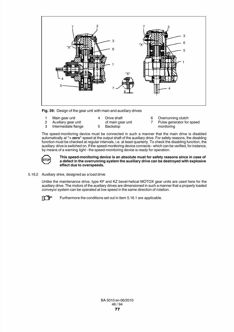
8/15/2019 r1_OF 71289_6 FF-AHF
http://slidepdf.com/reader/full/r1of-712896-ff-ahf 207/333
46 / 94BA 5010 en 06/2010
3
6
5
1
27
4
3
6
1
27
7
4
5
"X""X"
"X"
Fig. 39: Design of the gear unit with main and auxiliary drives1 Main gear unit 4 Drive shaft 6 Overrunning clutch2 Auxiliary gear unit of main gear unit 7 Pulse generator for speed3 Intermediate flange 5 Backstop monitoring
The speed-monitoring device must be connected in such a manner that the main drive is disabledautomatically at "> zero" speed at the output shaft of the auxiliary drive. For safety reasons, the disablingfunction must be checked at regular intervals, i.e. at least quarterly. To check the disabling function, theauxiliary drive is switched on. If the speed-monitoring device connects - which can be verified, for instance,by means of a warning light - the speed-monitoring device is ready for operation.
This speed-monitoring device is an absolute must for safety reasons since in case ofa defect in the overrunning system the auxiliary drive can be destroyed with explosive
effect due to overspeeds.5.16.2 Auxiliary drive, designed as a load drive
Unlike the maintenance drive, type KF and KZ bevel-helical MOTOX gear units are used here for theauxiliary drive. The motors of the auxiliary drives are dimensioned in such a manner that a properly loadedconveyor system can be operated at low speed in the same direction of rotation.
Furthermore the conditions set out in item 5.16.1 are applicable.
77

8/15/2019 r1_OF 71289_6 FF-AHF
http://slidepdf.com/reader/full/r1of-712896-ff-ahf 208/333
47 / 94BA 5010 en 06/2010
5.16.3 Overrunning clutch
If the gear unit is fitted with an auxiliary drive in addition to the main drive, coupling is realized by anoverrunning clutch. This allows, when driving by the auxiliary drive, a torque transmission in one directionof rotation, while there is "free-wheeling operation" when driven by the main drive.
The output shaft of the main drive will rotate in the same direction of rotation both if the drive is effected viathe main motor and via the auxiliary drive.
The overrunning clutch is mounted in an adapter flange and integrated in the oil circuit of the gear unit.Maintenance and oil change take place simultaneously with maintenance and oil change of the main drive.
The overrunning clutch is provided with centrifugally operated grippers. If the main gear unit is rotating inthe specified direction of rotation, the inner ring will rotate together with the grippers, while the outer ringremains stationary. From a certain speed of rotation, the grippers will lift off and the overrunning clutch willoperate without wear. If the drive is effected by the motor of the auxiliary drive via the outer ring, theoverrunning clutch will be in "carrier operation", i.e. the main gear unit is turned over slowly in the chosendirection of rotation. At the same time, the drive shaft of the main gear unit and, if a flexible coupling is usedbetween main motor and gear unit, possibly the main motor will rotate slowly along with it.
The main motor and the motor of the auxiliary drive should be interlocked electrically in sucha manner that only one of the two motors can be switched on.
When driving via the auxiliary drive, the drive shaft of the main gear unit will rotate alongsimultaneously. This rotary motion must not be impeded. A brake arranged on the drive sidein the main drive must be released if the drive is effected via the auxiliary drive.
When filling the main gear unit with oil, start by supplying lubricating point 1 at theintermediate flange with the oil quantity and oil grade specified on the rating plate.Prior to startup, the overrunning clutch should be checked for proper functionaccording to item 7.2.4.
78

8/15/2019 r1_OF 71289_6 FF-AHF
http://slidepdf.com/reader/full/r1of-712896-ff-ahf 209/333
48 / 94BA 5010 en 06/2010
6. Fitting
Observe the instructions in section 3, "Safety instructions"!
6.1 General information on fitting
When transporting the gear unit observe the notes in section 4, "Transport and storage".
Fitting work must be done with great care by authorised, trained and qualified personnel. The manufacturer
cannot be held liable for damage caused by incorrect assembly and installation.During the planning phase sufficient space must be allowed around the gear unit for later care andmaintenance work.
Free convection through the surface of the housing must be ensured by suitable measures.
If the gear unit is fitted with a fan, there should be sufficient space for air intake.
Adequate lifting equipment must be available before beginning the fitting work.
During operation the unit must not be allowed to heat up through exposure to heatfrom external sources such as sunlight, and suitable measures must be taken toprevent this!
Such measures may be:– fitting a sunshade roof,
or– fitting an additional cooling unit,
or– fitting the oil sump with a temperature monitoring device with a cut-out function.
If a sunshade roof is fitted, heat must be prevented from building up!If a temperature monitoring device is fitted, a warning signal must be emitted when themaximum permitted oil-sump temperature is reached. If the maximum permittedoil-sump temperature is exceeded, the drive must be shut off.Such shutting off may cause the operator's system to stop!
The operator should ensure that no foreign bodies affect the proper function of thegear unit (e.g. falling objects or heaping over).
No electrical welding work must be done at all on the drive.The drives must not be used as an earthing point for welding operations. Toothedparts and bearings may be irreparably damaged by welding.
All the fastening points provided by the design of the unit must be used.Screws which have been damaged during assembly or disassembly work must bereplaced with new ones of the same strength class and type.
To ensure proper lubrication during operation, the mounting position specified on the drawingsmust always be observed.
79
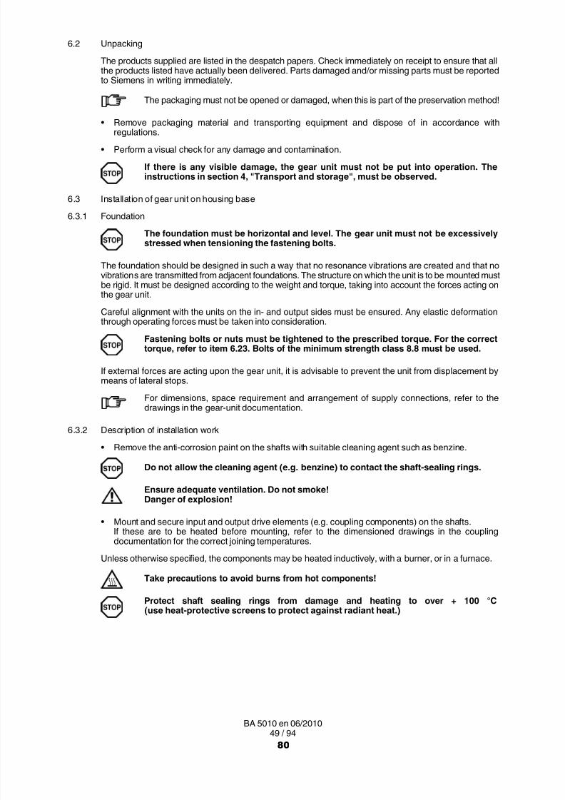
8/15/2019 r1_OF 71289_6 FF-AHF
http://slidepdf.com/reader/full/r1of-712896-ff-ahf 210/333

8/15/2019 r1_OF 71289_6 FF-AHF
http://slidepdf.com/reader/full/r1of-712896-ff-ahf 211/333
50 / 94BA 5010 en 06/2010
The components must be pushed smartly onto the shaft up to the position specified in the order-specificdimensioned drawing.
Fit the coupling with the aid of suitable fitting equipment. The parts must not be drivenon by abrupt force, as this may damage the gear unit (see also item 6.8).The shaft-sealing rings and running surfaces of the shaft must not be damaged whenpulling in the coupling parts.
When installing the drives, make absolutely certain that the individual components are
accurately aligned in relation to each other. Inadmissibly large errors in the alignmentof the shaft ends to be connected due to angular and/or axial misalignments result inpremature wear and/or material damage.Insufficiently rigid base frames or sub-structures can also during operation causea radial and/or axial misalignment, which cannot be measured when the unit is ata standstill.
Gear units whose weight requires the use of lifting gear must be attached at the points shownin section 4, "Transport and storage". If the gear unit is to be transported with add-on parts,additional attachment points may be required. The position of these attachment points isshown in the order related dimensioned drawing.
6.3.2.1 Alignment surfaces, alignment thread
Preliminary alignment of the gear units (sizes 3 to 12) in a horizontal direction is done by the surfaces ofthe inspection and/or assembly cover.
Aligning surface:
For the exact position of the aligning surfaces refer to the drawings in the gear-unit documentation.
The alignment surfaces are for aligning the gear unit horizontally, in order to ensure correct running of thegear unit.
The values punched into the alignment surfaces must always be observed.
11
Fig. 40: Alignment surfaces on gear unit up to size 12
81

8/15/2019 r1_OF 71289_6 FF-AHF
http://slidepdf.com/reader/full/r1of-712896-ff-ahf 212/333
51 / 94BA 5010 en 06/2010
Gear units of sizes 13 to 22 have special alignment surfaces on the top of the housing for preliminaryalignment of the gear units. To facilitate alignment of gear units of these sizes, alignment threads areprovided in the housing base.
1 1
2
1
2
Fig. 41: Alignment surfaces on gear units from size 13
1 Alignment surfaces 2 Alignment thread
The final fine alignment with the assemblies on the in- and output side must be carried out accurately bythe shaft axes, using:
• rulers
• spirit level
• dial gauge
• feeler gauge, etc.
Only then should the gear unit be fastened and afterwards the alignment be checked once again.
• Record alignment dimensions.
The report must be kept with these instructions.
The accuracy of shaft axis alignment is an important factor in determining the life spanof shafts, bearings and couplings. If possible, the deviation should be zero(exception: ZAPEX couplings). For amongst others the special requirements for thecouplings, refer to the specific operating instructions.
Non-observance can cause shaft rupture, resulting in serious injury or danger of life.
6.3.2.2 Mounting on a foundation frame
• Clean the undersurface of the gear-unit base.
• Using suitable lifting gear, place the gear unit on the foundation frame.
• Tighten the foundation bolts to the specified torque (see item 6.23); if necessary, use stops to preventdisplacement.
The gear unit must not be excessively stressed when tensioning the fastening bolts.
• Align the gear unit exactly with the input and output units (see item 6.3.2.1).
• Record alignment dimensions.
The report must be kept with these instructions.
82

8/15/2019 r1_OF 71289_6 FF-AHF
http://slidepdf.com/reader/full/r1of-712896-ff-ahf 213/333
52 / 94BA 5010 en 06/2010
6.3.2.3 Mounting on a concrete foundation by means of stone bolts or foundation blocks
• Clean the undersurface of the gear-unit base.
Placing stone bolts:
• Hook stone bolts with washers and hexagon nuts into the foundation fastening points on the gear-unithousing (see figure 42).
The hexagon nuts must only be tightened when the concrete has set.
4
5
321
1 Hexagon nut2 Washer3 Gear-unit base4 Stone bolt5 Foundation
Fig. 42: Stone bolt
Placing the foundation blocks:
• Hook the foundation blocks with washers and fastening bolts into the foundation fastening points onthe gear-unit housing (see figure 43).
The fastening bolts must only be tightened when the concrete has set.
4
5
9
6
321
7
8
1 Fastening bolt2 Washer3 Gear-unit base4 Threaded stud5 Flat steel plate6 Foundation7 Final foundation height8 Prepared foundation height9 Foundation block
Fig. 43: Foundation block
• Using suitable lifting gear, place the gear unit on the concrete foundation.
• Align gear unit horizontally by in- and output shafts:
─ if using stone bolts, with shims,
─ if using foundation blocks, with the aid of the set screws (if available).
• If considerable forces may apply, use stops to prevent the unit from displacement.
Before pouring the concrete foundation, fill up the openings in the foundation blocks withadequate material such as polystyrene.With types H1 and H2, remove the air-conducting cowl before tightening the foundation boltsand then bolt it back into position.
• Pour concrete into the recesses of the stone bolts or foundation blocks.
83
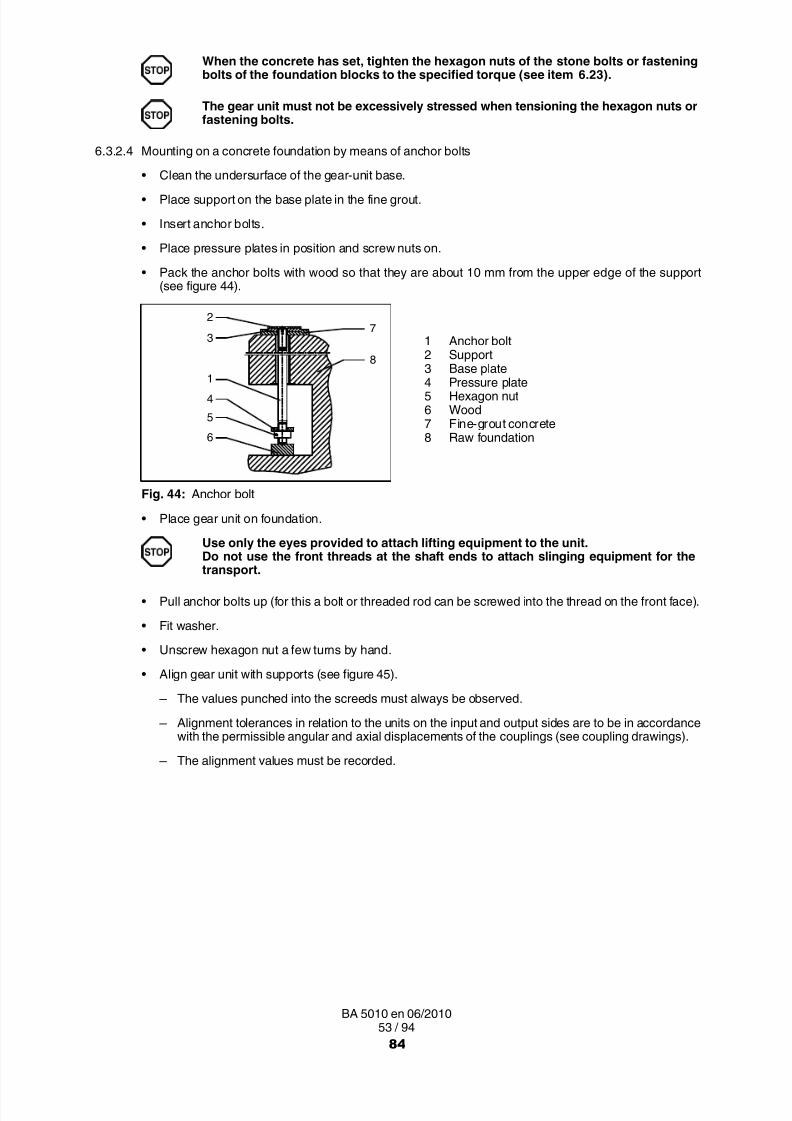
8/15/2019 r1_OF 71289_6 FF-AHF
http://slidepdf.com/reader/full/r1of-712896-ff-ahf 214/333
53 / 94BA 5010 en 06/2010
When the concrete has set, tighten the hexagon nuts of the stone bolts or fasteningbolts of the foundation blocks to the specified torque (see item 6.23).
The gear unit must not be excessively stressed when tensioning the hexagon nuts orfastening bolts.
6.3.2.4 Mounting on a concrete foundation by means of anchor bolts
• Clean the undersurface of the gear-unit base.
• Place support on the base plate in the fine grout.
• Insert anchor bolts.
• Place pressure plates in position and screw nuts on.
• Pack the anchor bolts with wood so that they are about 10 mm from the upper edge of the support(see figure 44).
4
6
5
2
3
1
7
8
1 Anchor bolt2 Support
3 Base plate4 Pressure plate5 Hexagon nut6 Wood7 Fine-grout concrete8 Raw foundation
Fig. 44: Anchor bolt
• Place gear unit on foundation.
Use only the eyes provided to attach lifting equipment to the unit.
Do not use the front threads at the shaft ends to attach slinging equipment for thetransport.
• Pull anchor bolts up (for this a bolt or threaded rod can be screwed into the thread on the front face).
• Fit washer.
• Unscrew hexagon nut a few turns by hand.
• Align gear unit with supports (see figure 45 ).
─ The values punched into the screeds must always be observed.
─ Alignment tolerances in relation to the units on the input and output sides are to be in accordancewith the permissible angular and axial displacements of the couplings (see coupling drawings).
─ The alignment values must be recorded.
84

8/15/2019 r1_OF 71289_6 FF-AHF
http://slidepdf.com/reader/full/r1of-712896-ff-ahf 215/333
54 / 94BA 5010 en 06/2010
4
5
2
3
1
7
8
6 1 Anchor bolt2 Support3 Base plate4 Washer5 Hexagon nut6 Housing base
7 Fine-grout concrete8 Raw foundation
Fig. 45: Anchor bolt
Prior to tensioning the anchor bolts, the fine-grout concrete must have set for at least28 days.
• Keep anchor bolts in their position by tightening the nut with your fingers.
• Place the protective sleeve.
• Place hydraulic tensioning device in position.
• Initially tension the bolts alternately (for initial tensioning forces, see item 6.23).
• Using a suitable tool, screw hexagon nuts on as far as the stop.
To ensure correct handling and adjustment of the pretensioning tool, the manufacturer’soperating instructions must be adhered to.
The tensioning pressures and/or the initial tensioning forces should be recorded (see also item 7.2.9).
6.4 Assembly of a shaft-mounting gear unit with hollow shaft and parallel keyway
The end of the driven-machine shaft (material C60+N or higher strength) must be provided with a parallel
key to DIN 6885 Part 1 Form A. Furthermore, a centring hole to DIN 332 Form DS (tapped) should beprovided (for the connection dimensions of the driven machine shaft, see dimensioned drawing in the gearunit documentation).
6.4.1 Preparatory work
To facilitate demounting (see also item 6.4.3), we recommend providing a connection for pressure oil onthe end of the driven machine shaft. For this a hole must be drilled through to the hollow shaft bore(see figure 46). This connection may also be used for supplying rust-releasing agent.
3
1
24
Fig. 46: Hollow shaft with parallel keyway, preparation
1 Machine shaft 3 Parallel key2 Hollow shaft 4 Pressure oil connection
85

8/15/2019 r1_OF 71289_6 FF-AHF
http://slidepdf.com/reader/full/r1of-712896-ff-ahf 216/333
55 / 94BA 5010 en 06/2010
6.4.2 Fitting
• Remove the preservative agent from the hollow shaft and the machine shaft with a suitable cleaningagent (such as benzine).
Do not allow the cleaning agent (e.g. benzine) to contact the shaft sealing rings.
Ensure adequate ventilation. Do not smoke!Danger of explosion!
• Check the hollow and machine shafts to ensure that seats and edges are not damaged. If necessary,rework the parts with a suitable tool and clean them again.
Coat with a suitable lubricant to prevent frictional corrosion of the contact surfaces.
6.4.2.1 Fitting
• Fit the gear unit by means of nut and threaded spindle. The counterforce is provided by the hollow shaft.
The hollow shaft must be exactly aligned with the machine shaft to avoid canting.
2
3
1
4
7
6
5
Fig. 47: Hollow shaft with parallel keyway, mounting with threaded spindle
1 Machine shaft 4 Nut 7 End plate2 Hollow shaft 5 Threaded spindle3 Parallel key 6 Nut
Instead of the nut and threaded spindle shown in the diagram, other types of equipment such as a hydrauliclifting equipment (type ”Lukas”) may be used.
The hollow shaft may be tightened against a machine-shaft collar only if the gear-unitconfiguration is one of the following:
– Torque arm– Support with gear-unit swing base
With a different arrangement the bearings may be excessively stressed during themounting procedure.
6.4.2.2 Axial fastening
Depending on type, secure the hollow shaft axially on the machine shaft (e.g. with locking ring, end plate,set screw).
86

8/15/2019 r1_OF 71289_6 FF-AHF
http://slidepdf.com/reader/full/r1of-712896-ff-ahf 217/333
56 / 94BA 5010 en 06/2010
6.4.3 Demounting
• Remove the axial securing device from the hollow shaft.
• If frictional corrosion has occurred on the seating surfaces, rust-releasing agent may be used in orderto facilitate forcing off the gear unit. The rust releaser can be injected through the pressure-oilconnection (see figure 46 ), e.g. using a pump.
• When the rust-releasing agent has taken effect, pull the gear unit off with the device (see figures 48and 49).
• Removing the gear unit from the driven-machine shaft can be done locally as follows:
─ using forcing screws in an end plate (see figure 49) or
─ using a central threaded spindle or
─ preferably using a hydraulic lifting unit ("Lukas").
The end plate and/or the auxiliary plate for forcing off the gear unit are not included in ourdelivery.Each of the two end faces of the hollow shaft is provided with 2 threaded holes (for dimensions,see figure 50 ) to receive bolts for fastening the end plate to the hollow shaft.
5
4
63
1
27
Fig. 48: Hollow shaft with parallel keyway, demounting with hydraulic lifting equipment ("Lukas")
1 Machine shaft 5 Threaded spindle2 Hollow shaft 6 Pressure oil connection3 Parallel key 7 Plate for forcing out4 Hydraulic lifting unit ("Lukas")
5
4
6
3
1
2
Fig. 49: Hollow shaft with parallel keyway, demounting with end plate
1 Machine shaft 4 End plate for forcing out2 Hollow shaft 5 Screws3 Parallel key 6 Forcing screws
Avoid canting when pulling the unit off.
87

8/15/2019 r1_OF 71289_6 FF-AHF
http://slidepdf.com/reader/full/r1of-712896-ff-ahf 218/333
57 / 94BA 5010 en 06/2010
The plate for forcing-out is not included in our delivery.
4
3
1
2
Fig. 50: Hollow shaft with parallel keyway
*) 2 threads offset 180°
Table 15: Threaded holes on the end faces of the gear-unit hollow shafts
Gear-unitsize
mmm
s tmm
Gear-unitsize
mmm
s tmm
4 95 M 8 14.5 12 215 M 12 19.5
5 115 M 8 14.5 13 230 M 12 19.5
6 125 M 8 14.5 14 250 M 12 19.5
7 140 M 10 17 15 270 M 16 24
8 150 M 10 17 16 280 M 16 24
9 160 M 10 17 17 300 M 16 24
10 180 M 12 19.5 18 320 M 16 24
11 195 M 12 19.5 19 ... 22 on request
If the counterforce is provided not only by the hollow shaft, but also by the housing,as shown in figure 48, the forces used must not exceed the values given in thefollowing table 16.
Table 16: Maximum forcing pressures
Gear-unitsize
Maximum forcingpressure
N
Gear-unitsize
Maximum forcingpressure
N
4 22600 12 113600
5 33000 13 1400006 37500 14 160000
7 50000 15 193000
8 56000 16 215000
9 65000 17 240000
10 82000 18 266000
11 97200 19 ... 22 on request
If the above values are exceeded, the housing, the hollow-shaft bearings or other gearcomponents may be irreparably damaged. Before replacing the gear unit on themachine shaft, always check the bearings for any signs of damage.
When using forcing screws or threaded spindles, the head of the thread pressing against thedriven machine should be rounded and well greased to reduce the risk of seizing at this point.
88

8/15/2019 r1_OF 71289_6 FF-AHF
http://slidepdf.com/reader/full/r1of-712896-ff-ahf 219/333
58 / 94BA 5010 en 06/2010
6.5 Shaft-mounting gear unit with hollow shaft and internal spline to DIN 5480
The shaft end of the driven machine must be designed with internal splines to DIN 5480. Furthermore,a centring hole to DIN 332 Form DS (tapped) should be provided (for the connection dimensions of thedriven machine shaft, see dimensioned drawing in the gear unit documentation).
6.5.1 Preparatory work
To facilitate demounting (see also item 6.4.3), we recommend providing a connection for pressure oil onthe end of the driven machine shaft. For this a hole must be drilled through to the hollow shaft bore(see figure 51). This connection may also be used for supplying rust-releasing agent.
4
3
1
2
Fig. 51: Hollow shaft with internal spline, preparation
1 Machine shaft 3 DU bush2 Hollow shaft 4 Pressure oil connection
6.5.2 Fitting
• Remove the preservative agent from the hollow shaft and the machine shaft with a suitable cleaningagent (such as benzine).
Do not allow the cleaning agent (e.g. benzine) to contact the shaft sealing rings.
Ensure adequate ventilation. Do not smoke!Danger of explosion!
• Check the hollow and machine shafts to ensure that seats, teeth or edges are not damaged.If necessary, rework the parts with a suitable tool and clean them again.
Coat with a suitable lubricant to prevent frictional corrosion of the contact surfaces.
89
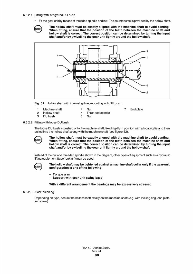
8/15/2019 r1_OF 71289_6 FF-AHF
http://slidepdf.com/reader/full/r1of-712896-ff-ahf 220/333
59 / 94BA 5010 en 06/2010
6.5.2.1 Fitting with integrated DU bush
• Fit the gear unit by means of threaded spindle and nut. The counterforce is provided by the hollow shaft.
The hollow shaft must be exactly aligned with the machine shaft to avoid canting.When fitting, ensure that the position of the teeth between the machine shaft andhollow shaft is correct. The correct position can be determined by turning the inputshaft and/or by swivelling the gear unit lightly around the hollow shaft.
7
5
6
3
1
4
2
Fig. 52: Hollow shaft with internal spline, mounting with DU bush
1 Machine shaft 4 Nut 7 End plate2 Hollow shaft 5 Threaded spindle3 DU bush 6 Nut
6.5.2.2 Fitting with loose DU bush
The loose DU bush is pushed onto the machine shaft, fixed rigidly in position with a locating tie and thenpulled into the hollow shaft along with the machine shaft (see figure 52).
The hollow shaft must be exactly aligned with the machine shaft to avoid canting.When fitting, ensure that the position of the teeth between the machine shaft andhollow shaft is correct. The correct position can be determined by turning the inputshaft and/or by swivelling the gear unit lightly around the hollow shaft.
Instead of the nut and threaded spindle shown in the diagram, other types of equipment such as a hydrauliclifting equipment (type "Lukas") may be used.
The hollow shaft may be tightened against a machine-shaft collar only if the gear-unitconfiguration is one of the following:
– Torque arm– Support with gear-unit swing base
With a different arrangement the bearings may be excessively stressed.
6.5.2.3 Axial fastening
Depending on type, secure the hollow shaft axially on the machine shaft (e.g. with locking ring, end plate,set screw).
90

8/15/2019 r1_OF 71289_6 FF-AHF
http://slidepdf.com/reader/full/r1of-712896-ff-ahf 221/333

8/15/2019 r1_OF 71289_6 FF-AHF
http://slidepdf.com/reader/full/r1of-712896-ff-ahf 222/333

8/15/2019 r1_OF 71289_6 FF-AHF
http://slidepdf.com/reader/full/r1of-712896-ff-ahf 223/333
62 / 94BA 5010 en 06/2010
6.6.1.1 Fitting with integrated DU bush
• Fit the gear unit by means of nut and threaded spindle. The counterforce is provided by the hollow shaft.
The hollow shaft must be exactly aligned with the machine shaft to avoid canting.
7
5
6
3
1
4
2
Fig. 55: Hollow shaft in shrink-disk design, mounting with DU bush
1 Machine shaft 4 Nut 7 End plate2 Hollow shaft 5 Threaded spindle3 DU bush 6 Nut
6.6.1.2 Fitting with loose DU bush
The loose DU bush is pushed onto the machine shaft, fixed rigidly in position with a locating tie and thenpulled into the hollow shaft along with the machine shaft (see figure 55).
The hollow shaft must be exactly aligned with the machine shaft to avoid canting.
Instead of the nut and threaded spindle shown in the diagram, other types of equipment such as a hydrauliclifting equipment (type "Lukas") may be used.
The hollow shaft may be tightened against a machine-shaft collar only if the gear-unitconfiguration is one of the following:
– Torque arm– Support with gear-unit swing base
With a different arrangement the bearings may be excessively stressed.
6.6.1.3 Axial fastening
If the shrink disk is fitted according to instructions (see item 6.6), the gear unit is fixed securely in the axial
direction. Additional fastening is not required.
93

8/15/2019 r1_OF 71289_6 FF-AHF
http://slidepdf.com/reader/full/r1of-712896-ff-ahf 224/333
63 / 94BA 5010 en 06/2010
6.7 Shrink disk
The shrink disk realizes a press fit connection between a hollow shaft and a stub/machine shaft (in thefollowing called "stub shaft"). The interference fit can transfer torques, bending moments and forces. The jointing pressure between the hollow and stub shafts generated by the shrink disk is essential for the torqueand force transmission.
The shrink disk is delivered ready for installation.
The shrink disk must not be dismantled before mounting for the first time.
Mounting and start-up must be carried out by properly trained specialist personnel.Prior to start-up these instructions must be read, understood and adhered to. Weaccept no liability for personal injury or damage due to non-observance.
6.7.1 Fitting the shrink disk
• Before beginning installation, the hollow shaft and the stub shaft must be carefully cleaned.
Observe manufacturer’s instructions for handling lubricants and solvents.
Do not allow cleansing agent or solvent to affect surfaces with paint coating.
The bore of the hollow shaft and the stub shaft must be absolutely clean, free of greaseand oil in the area of the shrink disk seat.This is essential for safe and reliable torque transmission.Do not use contaminated solvents or dirty cloths nor cleansing agents containing oil(such as paraffin or terpentine) for removing grease.
B
W
A
1 2
3
5
4
Fig. 56: Fitting the shrink disk
A Greased B Absolutely grease- and oil-free W Installation height
1 Stub shaft 3 Inner ring 5 Tensioning bolt2 Hollow shaft 4 Outer ring
The outer surface of the hollow shaft must be lightly greased in the area of the shrink disk seat.
For a detailed view, refer to the dimensioned drawing in the gear-unit documentation.
• Place the shrink disk on the hollow shaft and fasten, if required. For the exact installation height (W) ofthe shrink disk, refer to the dimensioned drawing.
94

8/15/2019 r1_OF 71289_6 FF-AHF
http://slidepdf.com/reader/full/r1of-712896-ff-ahf 225/333
64 / 94BA 5010 en 06/2010
For transporting and lifting the shrink disk it may be required to use a suitable liftingdevice!
Make sure that the shrink disk cannot slip off the hollow shaft.
Do not tighten the tensioning bolts (5) until the stub shaft is installed too.
• Tighten the tensioning bolts (5) gradually one after the other, working round several times by quarter
turns.• Tighten all tensioning bolts (5) until the end faces of the inner ring (3) and the outer ring (4) are flush and
the maximum tightening torque of the tensioning bolts has been achieved. The correct alignment is tobe checked using a ruler. The max. tolerance is ± 0.2 mm.
The correct clamping condition can thus be checked visually.
To avoid overloading the individual bolts, the maximum tightening torque(see table 18) must not be exceeded. If, when tightening the clamping bolts at max.tightening torque, the inner and outer ring are not aligned, Siemens must beconsulted.
Table 18: Maximum torques for tensioning bolts
Tensioning-boltthread
max. tightening torqueper bolt Tensioning-bolt
thread
max. tightening torqueper bolt
Strength class 12.9Nm
Strength class 12.9Nm
M 8 35 M 20 570
M 10 70 M 24 980
M 12 120 M 27 1450
M 14 193 M 30 1970
M 16 295 M 33 2650
The shrink disk has been identity-marked on the outer ring (4). In case of contacting Siemensthis identification must be referred to.
For safety reasons, a protective cover should be mounted to prevent contact!This cover must be applied after completion of all works on the shrink disk.
Only the complete shrink disks supplied by the manufacturer may be used. Combiningof components from different shrink disks is not permitted.
Tightening the fastening bolts using an impact screwdriver is not permitted!
95

8/15/2019 r1_OF 71289_6 FF-AHF
http://slidepdf.com/reader/full/r1of-712896-ff-ahf 226/333
65 / 94BA 5010 en 06/2010
6.7.2 Demounting the shrink disk
• Remove the protective cover.
• Remove any rust deposits from the shaft and the hollow shaft.
Under no circumstances must the tensioning bolts be unscrewed one after the other.
• Undo all tensioning bolts one after the other by approx. 1/4 turn.
The stored energy of the outer ring is slowly loosened during disassembly via the bolts to beloosened. In order that this is carried out correctly, the procedure described here must becarefully adhered to!
• All tensioning bolts should now be further loosened one after the other by approx. 1 turn.
The outer ring should now release of its own accord from the inner ring. If this is not the case,the outer ring can be detensioned with the forcing threads. To this purpose screw some of theadjacent fastening bolts into the forcing threads. The now loosening outer ring is bracedagainst the remaining bolts. This operation must be carried out until the outer ring completelyreleases of its own accord.
• The shrink disk is to be secured against axial shifting.
• Draw the stub shaft out of the hollow shaft.
• Pull the shrink disk off the hollow shaft.
For transporting and lifting the shrink disk it may be required to use a suitable liftingdevice!
6.7.3 Cleaning and greasing the shrink disk
Only dirty shrink disks must be disassembled and cleaned.
• Inspection of all parts for any damage.
Damaged parts must be replaced with new ones! The use of damaged parts is notpermissible!
Only the complete shrink disks supplied by the manufacturer may be used. Combiningof components from different shrink disks is not permitted.
• Thoroughly clean all parts.
Do not use contaminated solvents or dirty cloths nor cleansing agents containing oil(such as paraffin or terpentine) for removing grease.
• The conical surfaces of the inner and outer rings (3 and 4, see figure 56 ) must be free of grease andoil.
─ A thin layer of grease must be applied evenly to the conical surfaces of the inner and outer rings(3 and 4, see figure 56 ).
─ Provide the tensioning bolts (5, see figure 56 ) on the contact surface and on the thread withlubricant.
96

8/15/2019 r1_OF 71289_6 FF-AHF
http://slidepdf.com/reader/full/r1of-712896-ff-ahf 227/333
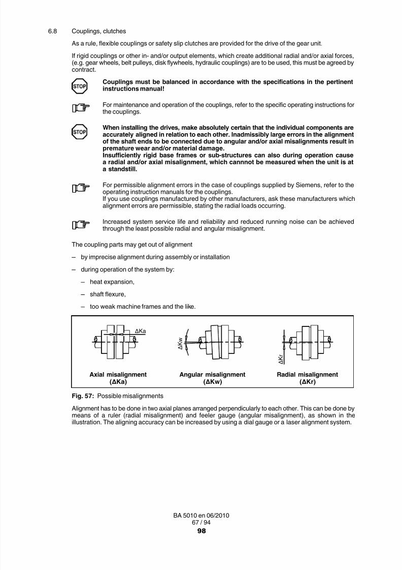
8/15/2019 r1_OF 71289_6 FF-AHF
http://slidepdf.com/reader/full/r1of-712896-ff-ahf 228/333
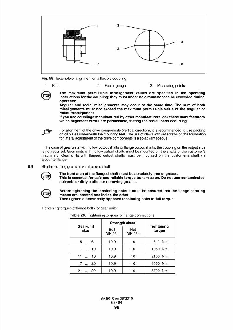
8/15/2019 r1_OF 71289_6 FF-AHF
http://slidepdf.com/reader/full/r1of-712896-ff-ahf 229/333
68 / 94BA 5010 en 06/2010
3
3
3
31
2
Fig. 58: Example of alignment on a flexible coupling
1 Ruler 2 Feeler gauge 3 Measuring points
The maximum permissible misalignment values are specified in the operatinginstructions for the coupling; they must under no circumstances be exceeded duringoperation.Angular and radial misalignments may occur at the same time. The sum of both
misalignments must not exceed the maximum permissible value of the angular orradial misalignment.If you use couplings manufactured by other manufacturers, ask these manufacturerswhich alignment errors are permissible, stating the radial loads occurring.
For alignment of the drive components (vertical direction), it is recommended to use packingor foil plates underneath the mounting feet. The use of claws with set screws on the foundationfor lateral adjustment of the drive components is also advantageous.
In the case of gear units with hollow output shafts or flange output shafts, the coupling on the output sideis not required. Gear units with hollow output shafts must be mounted on the shafts of the customer’smachinery. Gear units with flanged output shafts must be mounted on the customer’s shaft viaa counterflange.
6.9 Shaft-mounting gear unit with flanged shaft
The front area of the flanged shaft must be absolutely free of grease.This is essential for safe and reliable torque transmission. Do not use contaminatedsolvents or dirty cloths for removing grease.
Before tightening the tensioning bolts it must be ensured that the flange centringmeans are inserted one inside the other.Then tighten diametrically opposed tensioning bolts to full torque.
Tightening torques of flange bolts for gear units:
Table 20: Tightening torques for flange connections
Gear-unitsize
Strength classTightening
torqueBoltDIN 931
NutDIN 934
5 ... 6 10.9 10 610 Nm
7 ... 10 10.9 10 1050 Nm
11 ... 16 10.9 10 2100 Nm
17 ... 20 10.9 10 3560 Nm
21 ... 22 10.9 10 5720 Nm
99

8/15/2019 r1_OF 71289_6 FF-AHF
http://slidepdf.com/reader/full/r1of-712896-ff-ahf 230/333
69 / 94BA 5010 en 06/2010
6.10 Shaft mounting gear unit with block flange
The front area of the block flange must be absolutely free of grease.This is essential for safe and reliable torque transmission. Do not use contaminatedsolvents or dirty cloths for removing grease.
Tighten diametrically opposed tensioning bolts to full torque.
The joint bolts must be tightened to the prescribed torque. For the correct torque, referto item 6.23. Bolts of the minimum strength class 8.8 must be used. The transmittablegear-unit torque is limited by the bolted joint on bolt circle K 1.
ØK1
Fig. 59: Illustration with block flange
Table 21: Types and rotation directions
TypeType 1)
B C
H2..
H3..
H4..
B2..
B3..
B4..
1) Types with hollow output shaft on request
100

8/15/2019 r1_OF 71289_6 FF-AHF
http://slidepdf.com/reader/full/r1of-712896-ff-ahf 231/333
70 / 94BA 5010 en 06/2010
6.11 Mounting the torque arm for the gear unit housing
6.11.1 Attaching the torque arm
The torque arm must be mounted stress-free on the machine side
On helical gear units with a motor bell housing the torque arm is located opposite the motor bell housing.
1
2
Fig. 60: Torque arm for gear-unit housing1 Machine side 2 Flexible support block
Table 22: Motor types and torque arms
Gear-unitsize
Max. perm. standard-motor size
Gear type Gear type
H2 H3 H4 B2 B3 B4
4 200 200 200
5 ... 6 225 225 225 225 1607 ... 8 280 280 180 280 280 200
9 ... 10 280 280 225 280 280 225
11 ... 12 315M 315M 250 315M 315M 280
13 ... 14 355 315M 355 355 315M
15 ... 16 355 315 355 355M
17 ... 18 355 355M 355 355
19 ... 22 on request
Larger motors should be used only with the approval of Siemens.
• Foundation type for fastening the torque arm, see item 6.3.1, "Foundation".
• If the customer fits a torque arm, connection to the foundation must be by means of a flexible element.
101

8/15/2019 r1_OF 71289_6 FF-AHF
http://slidepdf.com/reader/full/r1of-712896-ff-ahf 232/333
71 / 94BA 5010 en 06/2010
6.12 Mounting supports for gear-unit swing bases
6.12.1 Attaching the support
The support for the gear unit swing base must be mounted free of stress.
2
3
1
5
2 1
4 3
Fig. 61: Support for gear-unit swing base
1 Gear unit 4 Torque arm2 Motor 5 Flexible support block3 Gear-unit swing base
Table 23: Motor assignment gear-unit swing base
Gear-unitsize
Max. perm.standard-motor size
Gear type
B2 B3 B4
4
onrequest
200
5 ... 6 225M 160
7 ... 8 280M 200
9 ... 10 315 225M
11 ... 12 355 280S
13 ... 14 400M 315M
15 ... 16 400M 315
17 ... 18 400M 355L
19 ... 22on request
Larger motors should be used only with the approval of Siemens.
• Foundation type for fastening the torque arm, see item 6.3.1, "Foundation".
• If the customer fits a torque arm, connection to the foundation must be by means of a flexible element.
102

8/15/2019 r1_OF 71289_6 FF-AHF
http://slidepdf.com/reader/full/r1of-712896-ff-ahf 233/333
72 / 94BA 5010 en 06/2010
6.13 Gear units with cooling coil
• Before connecting the cooling coil the screw plugs must be removed from the connecting bushes.
• Flush the cooling coil (in order to remove any contamination).
• Connect the cooling-water in- and outflow pipes (for exact position of the connections, seedimensioned drawing).
Observe also item 5.10.2.
6.14 Gear unit with add-on components
• For the technical data to the add-on components, as stated in item 6.15 to 6.21, refer to theorder-specific list of equipment.
• The electrical equipment for regulation and control must be wired in accordance with the equipmentsuppliers' instructions.
• For operation and maintenance the operating instructions provided specifically for the order and thespecifications in items 5.10.2 to 5.15 must be observed.
6.15 Gear units with air oil-cooler
• Connect the contamination indicator for switchover filter (for gear sizes ≥13) and pressure monitorelectrically.
• Connect the fan motor electrically.
6.16 Gear units with fitted water oil-cooler
• Before connecting the water oil-cooler remove the plugs from the cooling-water connections.
• Flush the water oil-cooler (in order to remove any contamination).
• Install the cooling-water in- and outflow pipes (for flow direction and exact position of connections, seedimensioned drawing).
Make sure when installing the piping that no forces, moments or vibrations act uponthe connections of the water oil-cooler.
• Wire the pressure monitor electrically (in case of gear units with corresponding equipment only).
Observe also item 5.10.4.
6.17 Gear unit with heating element
• Wire heating elements electrically.
6.18 Gear unit with oil temperature monitoring system
• Wire resistance thermometer with evaluating instrument (to be provided by customer) electrically.
6.19 Gear unit with oil-level monitoring
• Wire the level-limit switch electrically.
• Wire oil-level monitor electrically.
6.20 Bearing-monitoring system
• The bearing monitoring device must be fitted by the customer.
6.21 Gear unit with speed transmitter
• Wire speed transmitter electrically.
103

8/15/2019 r1_OF 71289_6 FF-AHF
http://slidepdf.com/reader/full/r1of-712896-ff-ahf 234/333
73 / 94BA 5010 en 06/2010
6.22 Final work
• After installation of the gear unit check all screw connections for tight fit.
• Check the alignment after tightening the fastening elements (the alignment must not have beenchanged).
• Check that all the devices which have been demounted for transport reasons have been refitted.For this refer to the details in the data sheet, the list of equipment and the associated drawings.
• Any oil drain cocks must be secured against accidental opening.• The gear unit must be protected against falling objects.
• Protective devices for rotating parts must be checked for correct seating. Contact with rotating partsis not permitted.
• A potential equalisation in accordance with the applying regulations and directives must be carried out!If no threaded holes for earth connection are available on the gear unit, other appropriate measuresmust be taken. This work must always be done by electrotechnical specialists.
• Cable entries should be protected against moisture.
• Check that protective measures have been taken!
6.23 Screw-connection classes, tightening torques and initial tensioning forces6.23.1 Screw-connection classes
The specified screw connections are to be fastened applying the tightening torques specified in the tablebelow.
Table 24: Screw-connection classes
Screw-connectionclass
Distributionof emitted torque
on the tool
Tightening procedure(Usually the tightening processes lie
within the stated tool distribution)
C ± 5 % up to ± 10 %
‐ Hydraulic tightening with mechanical screwdriver
- Torque-controlled tightening with torque wrench,signal-emitting torque wrench- Tightening with precision mechanical screwdriver
with dynamic torque measuring
D ± 10 % up to ± 20 % ‐ Torque-controlled tightening with mechanical screwdriver
E ± 20 % up to ± 50 %‐ Tightening with pulse screwdriver or impact wrench
without adjustment checking device- Tightening by hand, using a spanner
without torque measuring device
104

8/15/2019 r1_OF 71289_6 FF-AHF
http://slidepdf.com/reader/full/r1of-712896-ff-ahf 235/333

8/15/2019 r1_OF 71289_6 FF-AHF
http://slidepdf.com/reader/full/r1of-712896-ff-ahf 236/333
75 / 94BA 5010 en 06/2010
Nominalthread
diameter
Tightening torquefor screw-connection classes
from table 22
Initial tensioning forcefor screw-connection classes
from table 22
Strengthclass of the
screwEDCEDC
dmm
MANm
FM min.N
M80x68.8 1190000 760000 475000 21500 18500 16500
10.9 1690000 1100000 675000 30500 26400 23400
12.9 1980000 1360000 790000 35700 31400 27400
M90x68.8 1510000 968000 605000 30600 26300 23500
10.9 2150000 1380000 860000 43500 37500 3340012.9 2520000 1600000 1010000 51000 43800 39200
M100x68.8 1880000 1200000 750000 42100 36200 32300
10.9 2670000 1710000 1070000 60000 51600 4610012.9 3130000 2000000 1250000 70000 60400 53900
Damaged bolts must be replaced with new bolts of the same type and strength class.
7. Start-upObserve the instructions in section 3. , "Safety instructions"!
The gear unit must not be started up if the required instructions are not to hand.
7.1 Procedure before start-up
7.1.1 Removal of preservative agent
The location of the oil-draining points is marked by an appropriate symbol in the dimensioned drawing inthe gear-unit documentation.
Oil-draining point:
• Place suitable containers under the oil-draining points.
• Unscrew the oil drain plug or open the oil drain cock.
• Remove remaining preservative agent and/or running-in oil from the gear unit using a suitablecontainer, unscrew any existing residual-oil drain plugs, to do so.
• Dispose of remaining preservative agent and/or running-in oil in accordance with regulations.
Remove any oil spillage immediately with an oil-binding agent.The oil must not come into contact with the skin (e.g. the operator’s hands).The safety notes on the data sheets for the oil used must be observed here!
• Screw in oil drain plug or reclose oil drain cock.
• Screw in any unscrewed residual-oil drain plugs again.
A detailed view of the gear unit can be obtained from the drawings in the gear-unit documentation.
106
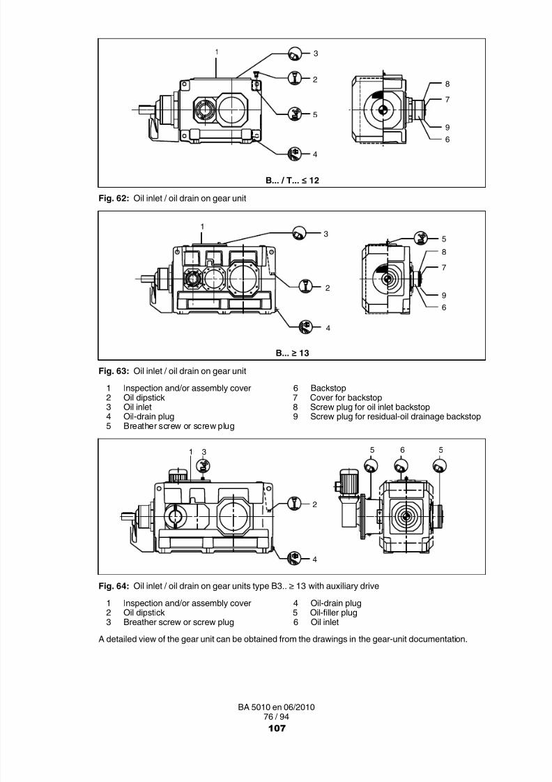
8/15/2019 r1_OF 71289_6 FF-AHF
http://slidepdf.com/reader/full/r1of-712896-ff-ahf 237/333
8/15/2019 r1_OF 71289_6 FF-AHF
http://slidepdf.com/reader/full/r1of-712896-ff-ahf 238/333

8/15/2019 r1_OF 71289_6 FF-AHF
http://slidepdf.com/reader/full/r1of-712896-ff-ahf 239/333

8/15/2019 r1_OF 71289_6 FF-AHF
http://slidepdf.com/reader/full/r1of-712896-ff-ahf 240/333
79 / 94BA 5010 en 06/2010
Table 27: Approximate values for required oil quantities in horizontal gear units with labyrinth seals
TypeOil quantity (approximate value) in litres for size
3 4 5 6 7 8 9 10 11 12 13 14 15 16 17 18 19 20 21 22
H1SH 5.5 19 36 60 106 155 156 225 ‐ ‐ ‐ ‐
H2SH 4.5 7 11 12 21 23 33 34 58 60 120 130 190 200 260 270 ‐ ‐ ‐ ‐
H2PH ‐ 25 45 72 110 ‐ ‐ ‐ ‐ ‐ ‐ ‐
Table 28: Approximative values for additional oil quantities for the intermediate flange when adding onthe auxiliary drive to the main gear unit
TypeAdditional oil quantity (approximate value) in litres for size
4 5 6 7 8 9 10 11 12
B3.HT3.H 1 2 2 5 5 5 6 12 12
TypeAdditional oil quantity (approximate value) in litres for size
13 14 15 16 17 18 19 20 21 22
B3.H 15 15 20 20 25 25 40 40 60 60
For details regarding the auxiliary gear unit, see the Special operating instructions.(The auxiliary gear unit is delivered ex works with oil filling.)
7.2 Start-up
Before start-up, replace the yellow plastic screw plug with the air filter (see notice ongear unit).
7.2.1 Oil level
The oil level must be monitored by means of the existing oil-level monitoring equipment. To do so, the gearunit must be shut down.When the oil is cool, the level should be at the upper mark on the oil dipstick or the middle of oil sight glass.When the oil is warm it may slightly exceed these marks.
It must in no case be allowed to fall below the mark. If necessary, top up to the correctlevel.
7.2.2 Gear unit with cooling coil or external oil-supply system
The permissible pressure and temperature values specified in the data sheet and/or list ofequipment must not be exceeded.This is to be checked before the start-up.
• Fully open the stop valves in the coolant in- and outflow pipes of the cooling system.
• Check that connecting lines are correctly fastened and tight.
For connecting dimensions, refer to the dimensioned drawing of the gear unit. The requiredcooling water quantity and the max. permissible inlet temperature are given on the data sheetand/or the list of equipment.
110

8/15/2019 r1_OF 71289_6 FF-AHF
http://slidepdf.com/reader/full/r1of-712896-ff-ahf 241/333
80 / 94BA 5010 en 06/2010
7.2.3 Gear unit with backstop
Observe details at item 5.8, "Backstop"!
Before start-up, check whether the backstop can be turned manually in the free-wheeling direction withoutexerting undue force. Observe the direction-of-rotation arrows on the housing.
To avoid damaging the backstop or the gear unit, the motor must not be run adverselyto the stop direction of the gear unit.
Observe the notice fixed to the gear unit.The minimum lift-off speeds must not be exceeded during operation.
If a backstop with release mechanism is used, the operating instructions for thisbackstop must be followed.Moreover, the dimension "x min." must be checked; "x min." must not be smaller thanthat stated on the backstop rating plate.
Before connecting the motor, determine the direction of rotation of the three-phase current supply usinga phase-sequence indicator, and connect the motor in accordance with the pre-determined direction ofrotation.
The unit can be started up once the amount of oil indicated on the notice has beenpoured in through the oil filler plug screw of the backstop. Always use oil of the sametype and viscosity as for the gear unit.
7.2.4 Gear unit with overrunning clutch
Observe details at item 5.16.3, "Overrunning clutch"!
Before start-up, check whether the overrunning clutch can be turned manually in the free-wheelingdirection without exerting undue force. Observe the direction-of-rotation arrows on the housing.
The overrunning clutch is in free-wheeling operation if the motor shaft of the auxiliary drive isrotated in opposed operating direction of rotation.When rotating in the operating direction of rotation, the blocking action of the overrunningclutch (carrier operation) becomes effective. Coupling and, thus, rotation of the output shaft ofthe main gear unit in operating direction of rotation takes place.In the case of auxiliary drives designed for load operation, the brake at the auxiliary motor mustfirst be lifted in order to check for proper functioning of the overrunning clutch.
The overrunning clutch is accommodated within the intermediate flange and is supplied with oil from themain gear unit.
7.2.5 Temperature measurement
During first start-up and after maintenance work, the oil sump temperature must bemeasured during correct use (maximum machine performance) after appropriaterunning in.
The maximally permissible oil-sump temperature is 90 °C (for mineral oil) or 100 °C(for synthetic oil).
At higher temperatures the gear unit must be shut down immediately and Siemenscustomer service consulted.
111

8/15/2019 r1_OF 71289_6 FF-AHF
http://slidepdf.com/reader/full/r1of-712896-ff-ahf 242/333
81 / 94BA 5010 en 06/2010
7.2.6 Oil-level monitoring system
This monitoring is designed as a standstill monitoring (gear‐unit stop) and checks the level ofthe oil before the unit is started up. When the signal "oil level too low" is given, it should be wiredin such a way that the drive motor cannot start and an alarm is given. During operation, anyactive signal should be bridged.
7.2.7 Bearing monitoring (vibration measurement)
If the necessary measures have been made for vibration measurement as bearingmonitoring (see item 5.14), vibration measurements must be taken in order to obtaininitial values and/or standard values for the diagnosis. These measurements must berecorded and filed.
7.2.8 Heating
Never switch the heating on, unless complete immersion of the rod heater in the oilbath is ensured. Fire hazard!If heating elements are installed afterwards the maximum heating capacity(see table 14 in item 5.11) on the outer surface of the heating element must not beexceeded.
The correct setting of the switch points must be checked!
7.2.9 Checking procedure
The following visual checks must be conducted and recorded when starting up:
□ Oil level
□ Leaktightness of the oil-cooling or oil-supply lines
□ Opening condition of the shut-off valves
□ Effectiveness of the shaft seals
□ Freedom of the rotating parts from contact
The tension pressures and/or pretensioning forces in accordance with item 6.3.2.4 must also be recordedin this document.
The document must be kept with the instructions.
7.3 Removal from service
• To take the gear unit out of service, first switch off the drive unit.
Secure the drive unit to prevent it from being started up unintentionally.Attach a warning notice to the start switch!
• In the case of gear units fitted with cooling coil or water oil-coolers, close the stop valves on the waterin- and outflow pipes. To prevent freezing, drain the water from the cooling coil or the water oil-cooler.
• Start the gear unit and allow it to run briefly (5 to 10 minutes) approx. every 3 weeks (during a shut-downperiod no longer than 6 months).
• Treat the gear unit with preservative, see items 7.3.1 and 7.3.2 (before a shut-down period exceeding6 months).
112

8/15/2019 r1_OF 71289_6 FF-AHF
http://slidepdf.com/reader/full/r1of-712896-ff-ahf 243/333
82 / 94BA 5010 en 06/2010
7.3.1 Interior preservation during longer disuse
Depending on the type of lubrication and/or shaft sealing, the following types of interior preservation canbe applied.
7.3.1.1 Interior preservation with gear oil
Gear units with splash-lubrication systems and contacting shaft seals can be filled with the correct type ofservice oil up to a point just below the air filter.
7.3.1.2 Interior preservation with preservative agentBefore longer shut-down periods gear units with pressure lubrication systems, oil circulation coolingand/or non-contacting shaft seals should be filled with preservative agent and run without load.
7.3.1.3 Interior-preservation procedure
• Stop the gear unit.
• Drain oil into a suitable container (see section 10. , "Maintenance and Repair").
• Unscrew the air filter including the reducing screw.
• Pour in the preservative agent through the hole of the reducing screw up to the top mark on the oil-sightglass.
For preservative agent see table 8 or 9 in item 4.4.1!
• Screw in air filter including reducing screw.
• Start the gear unit and allow it to idle briefly.
• Unscrew the oil drain plug.
• Drain preservative agent into a suitable container.
• Dispose of preservative agent in accordance with regulations.
There is a risk of scalding from the hot preservative agent draining from the gear unit.Wear protective gloves!
• Screw in the oil drain plug.
• Replace air filter with screw plug.
Before re-starting the gear unit, replace the screw plug with the air filter. Observe theinstructions in item 7.1.1.
7.3.2 Exterior preservation
7.3.2.1 Exterior-preservation procedure
• Clean the surfaces.
For separation between the sealing lip of the shaft-sealing ring and the preservative agent, theshaft should be brushed with grease in way of the sealing lip.
• Apply preservative agent.
For preservative agent see table 10 in item 4.4.2!
113

8/15/2019 r1_OF 71289_6 FF-AHF
http://slidepdf.com/reader/full/r1of-712896-ff-ahf 244/333
83 / 94BA 5010 en 06/2010
8. Operation
Observe the instructions in section 3. , "Safety instructions", in section 9, "Faults, causes and remedy", andin section 10. , "Maintenance and repair"!
8.1 General
To achieve a satisfactory and trouble-free operation of the equipment, be certain to observe the operatingvalues specified in section 1, "Technical Data", as well as the information given in the operating instructions
of the oil-supply system, if applicable.During operation the gear unit must be monitored for:
• Operating temperature The gear unit is designed for an operating temperature of:90 °C (mineral oil only)The maximum permitted temperature is:100 °C (synthetic oil only)
• Oil pressure of the oil-supply system (min. 0.5 bar)
• Changes in gear noise
• Possible oil leakage at the housing and shaft seals
8.2 Oil levelTo check the oil level, stop operation of the gear unit.When the oil is warm, the oil level may slightly exceed the upper mark of the oil dipstick or themiddle of the oil sight glass. It must not be allowed to fall below the lower mark. If necessary,top up to the correct level.
The oil level in the oil-supply system must be checked.For this, the operating instructions of the oil-supply system must be observed!
8.3 Irregularities
The drive unit must be switched off at once,
– if irregularities are found during the operationor
– if the pressure monitoring device in the oil-cooling system triggers alarm(only with correspondingly equipped gear units).
Determine the cause of the fault, using table 29, "Faults, causes and remedy"(see item 9.2).
Table 29, "Faults, causes and remedies", contains a list of possible faults, their causesand suggested remedies.
If the cause cannot be found, a specialist from one of our customer-service centresshould be called in (see section 2).
114

8/15/2019 r1_OF 71289_6 FF-AHF
http://slidepdf.com/reader/full/r1of-712896-ff-ahf 245/333
84 / 94BA 5010 en 06/2010
9. Faults, causes and remedy
Observe the instructions in section 3. , "Safety instructions", and in section 10. , "Maintenance and repair"!
9.1 General information on faults and malfunctions
Faults and malfunctions occurring during the guarantee period and requiring repair work on thegear unit must be carried out only by Siemens customer service.In the case of faults and malfunctions occurring after the guarantee period and whose cause
cannot be precisely identified, we advise our customers to contact our customer service.
Siemens will not be bound by the terms of the guarantee or otherwise be responsiblein cases of improper use of the gear unit, modifications carried out without theagreement of Siemens or use of spare parts not supplied by Siemens.
To remedy faults and malfunctions, the gear unit must always be taken out of service.Secure the drive unit to prevent it from being started up unintentionally.Attach a warning notice to the start switch!
9.2 Possible faults
Table 29: Faults, causes and remedy
Faults Causes Remedy
Changes in gear-unit noise. Damage to gear teeth.
Excessive bearing play.
Bearing defective.
Contact Customer Service.Check all toothed componentsand replace any damaged parts.
Contact Customer Service.Adjust bearing backlash.
Contact Customer Service.Replace defective bearings.
Loud noises in the areaof the gear-unit fastening.
Gear-unit fastening has workedloose.
Tighten bolts / nuts to specifiedtorque.Replace damaged bolts / nuts.
Increased temperatureat the bearing points.
Oil level in gear-unit housing too lowor too high.
Oil too old.
Oil-supply system defective.
Bearing defective.
Check oil level at room temperatureand, if necessary, top up oil.
Check date of last oil change and,if necessary, change oil.See section 10.
Check the oil-supply system,replace any defective parts.Consult operating instructionsfor oil-supply system.
Contact Customer Service.
Check and, if necessary,replace bearings.
Exterior of gear unit is oiled up. Inadequate sealing of housingcovers and/or joints.
Seal joints.
115
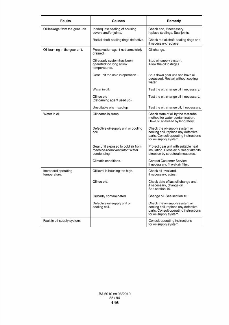
8/15/2019 r1_OF 71289_6 FF-AHF
http://slidepdf.com/reader/full/r1of-712896-ff-ahf 246/333
85 / 94BA 5010 en 06/2010
Faults RemedyCauses
Oil leakage from the gear unit. Inadequate sealing of housingcovers and/or joints.
Radial shaft-sealing rings defective.
Check and, if necessary,replace sealings. Seal joints.
Check radial shaft-sealing rings and,if necessary, replace.
Oil foaming in the gear unit. Preservation agent not completely
drained.Oil-supply system has beenoperated too long at lowtemperatures.
Gear unit too cold in operation.
Water in oil.
Oil too old(defoaming agent used up).
Unsuitable oils mixed up
Oil change.
Stop oil-supply system.Allow the oil to degas.
Shut down gear unit and have oildegassed. Restart without coolingwater.
Test the oil, change oil if necessary.
Test the oil, change oil if necessary.
Test the oil, change oil, if necessary.Water in oil. Oil foams in sump.
Defective oil-supply unit or coolingcoil.
Gear unit exposed to cold air frommachine-room ventilator: Watercondensing.
Climatic conditions.
Check state of oil by the test-tubemethod for water contamination.Have oil analysed by laboratory.
Check the oil-supply system orcooling coil, replace any defectiveparts. Consult operating instructionsfor oil-supply system.
Protect gear unit with suitable heatinsulation. Close air outlet or alter itsdirection by structural measures.
Contact Customer Service.If necessary, fit wet-air filter.
Increased operatingtemperature.
Oil level in housing too high.
Oil too old.
Oil badly contaminated.
Defective oil-supply unit orcooling coil.
Check oil level and,if necessary, adjust.
Check date of last oil change and,if necessary, change oil.See section 10.
Change oil. See section 10.
Check the oil-supply system orcooling coil, replace any defectiveparts. Consult operating instructionsfor oil-supply system.
Fault in oil-supply system. Consult operating instructionsfor oil-supply system.
116
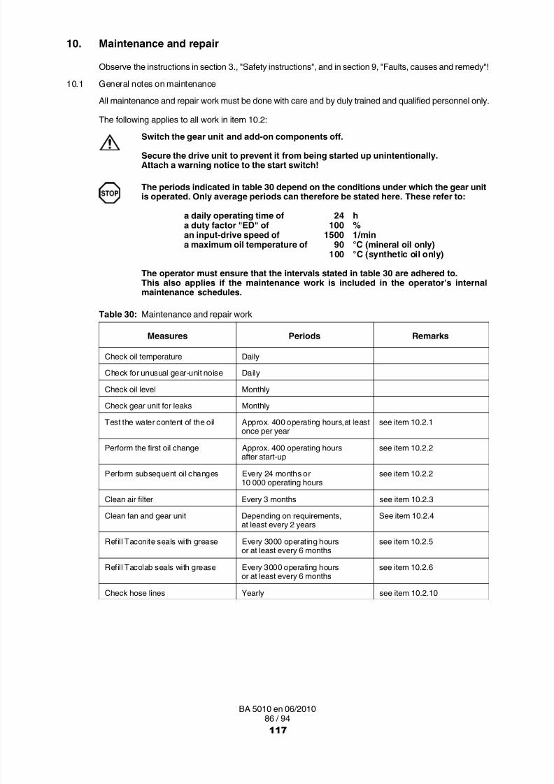
8/15/2019 r1_OF 71289_6 FF-AHF
http://slidepdf.com/reader/full/r1of-712896-ff-ahf 247/333
86 / 94BA 5010 en 06/2010
10. Maintenance and repair
Observe the instructions in section 3. , "Safety instructions", and in section 9, "Faults, causes and remedy"!
10.1 General notes on maintenance
All maintenance and repair work must be done with care and by duly trained and qualified personnel only.
The following applies to all work in item 10.2:
Switch the gear unit and add-on components off.
Secure the drive unit to prevent it from being started up unintentionally.Attach a warning notice to the start switch!
The periods indicated in table 30 depend on the conditions under which the gear unitis operated. Only average periods can therefore be stated here. These refer to:
a daily operating time of 24 ha duty factor "ED" of 100 %an input-drive speed of 1500 1/mina maximum oil temperature of 90 °C (mineral oil only)
100 °C (synthetic oil only)
The operator must ensure that the intervals stated in table 30 are adhered to.This also applies if the maintenance work is included in the operator’s internalmaintenance schedules.
Table 30: Maintenance and repair work
Measures Periods Remarks
Check oil temperature Daily
Check for unusual gear-unit noise Daily
Check oil level MonthlyCheck gear unit for leaks Monthly
Test the water content of the oil Approx. 400 operating hours,at leastonce per year
see item 10.2.1
Perform the first oil change Approx. 400 operating hoursafter start-up
see item 10.2.2
Perform subsequent oil changes Every 24 months or10 000 operating hours
see item 10.2.2
Clean air filter Every 3 months see item 10.2.3
Clean fan and gear unit Depending on requirements,at least every 2 years
See item 10.2.4
Refill Taconite seals with grease Every 3000 operating hoursor at least every 6 months
see item 10.2.5
Refill Tacolab seals with grease Every 3000 operating hoursor at least every 6 months
see item 10.2.6
Check hose lines Yearly see item 10.2.10
117

8/15/2019 r1_OF 71289_6 FF-AHF
http://slidepdf.com/reader/full/r1of-712896-ff-ahf 248/333
87 / 94BA 5010 en 06/2010
Measures RemarksPeriods
Change the hose lines 6 years from the manufacturing dateimpressed
see item 10.2.10
Check cooling coil Every 2 years see item 10.2.7
Check friction liningsof torque-limiting backstop
Once per year at least see item 5.9
Check auxiliary drive see item 5.16
Check tightness of fastening bolts After first oil change,then every 2 years
see item 10.2.14
Check shrink disk Every 12 months see item 6.7.5
Inspection of the gear unit Approx. every 2 years see item 10.4
10.1.1 General oil service lives
According to the manufacturers, the following are the expected periods during which the oils can be usedwithout undergoing any significant change in quality. They are calculated on the basis of an average oiltemperature of 80 °C:
─ for mineral oils, biologically degradable oils and physiologically safe (synthetic esters) oils 2 yearsor 10 000 operating hours (does not apply to natural esters such as rape seed oils) .
─ for poly-α‐olefins and polyglycols: 4 years or 20 000 operating hours.
The actual service lives may differ. The general rule is that an increase in temperature of 10 Kwill halve the service life and a temperature decrease of 10 K will approximately double theservice life.
10.2 Description of maintenance and repair work
10.2.1 Test water content of oil
More information about examining the oil for water content or conducting oil analyses is obtainable fromyour lubricant manufacturer or our customer service.
• For reference purposes, a fresh sample of the operating lubricating oil used must be sent with the usedoil sample to the analysing institute for analysis.
• The oil sample must be taken downstream of the filter of the oil-supply system while the gear unit isrunning. A suitable connection point is normally located upstream of the gear unit input (e.g. oil draincock in the pressure line).
• A special sample container should be filled with the specified quantity of oil.If there is no such sample container available, at least one litre of oil must be put in a clean ,transportworthy, sealable vessel.
10.2.2 Change oil
As an alternative to the oil change intervals indicated in table 30 (see item 10.1) it is possible to have theoil sample tested at regular intervals by the Technical Service of the relevant oil company and to have itreleased for further use.
If re usability has been confirmed, no oil change will be necessary.
Please observe the separately attached operating instructions BA 7300.
• The instructions in item 7.1 must be observed!
• Drain the oil while the gear unit is still warm, i.e. immediately after shutting down the machinery.
118

8/15/2019 r1_OF 71289_6 FF-AHF
http://slidepdf.com/reader/full/r1of-712896-ff-ahf 249/333
88 / 94BA 5010 en 06/2010
When changing the oil, always re-fill the gear unit with the same type of oil. Never mixdifferent types of oil and/or oils made by different manufacturers. Polyglycol-basedsynthetic oils in particular must not be mixed with PAO-based synthetic or mineral oils.If changing to a different grade or make of oil, the gear unit must, if necessary, beflushed out with the new oil grade. Flushing is not necessary, if the new service oil isfully compatible with the old service oil in all respects. Compatibility must beconfirmed by the oil supplier. If there is a change to another oil grade or make,Siemens recommends flushing out the gear unit with the new grade of service oil.
When changing the oil, the housing and the oil-supply system, if available, must be flushed withoil to remove sludge, metal particles and oil residue. Use the same type of oil as is used fornormal operation. High-viscosity oils must be heated beforehand using suitable means.Ensure that all residues have been removed before filling with fresh oil.
• Place a suitable container under the oil-draining point of the gear-unit housing.
• Unscrew the air filter including reducing screw at the housing top.
• Unscrew oil drain plug or open oil drain cock and drain the oil into the collecting container.
• Drain the oil from the oil-supply system (see operating instructions to the oil-supply system).
There is a danger of scalding from the hot oil emerging from the housing.
Wear protective gloves!Remove any oil spillage immediately with an oil-binding agent.
Check the condition of the sealing ring (the sealing ring is vulcanised onto the oil drain plug).If necessary, use a new oil drain plug.
• Screw in the oil drain plug or close oil drain cock.
• Clean the oil filter in the oil-cooling system (see operating instructions of the oil-supply system).
• Clean the air filter (see item 10.2.3).
• Screw in air filter including reducing screw.
• Fill fresh oil into the gear unit (see item 7.1.2).10.2.3 Clean the air filter
If a layer of dust has built up, the air filter must be cleaned, whether or not the minimum periodof 3 months has expired.
• Unscrew the air filter including the reducing screw.
• Clean the air filter using benzine or a similar cleanser.
• Dry the air filter and/or blow with compressed air.
Be especially careful when blowing with compressed air.Wear protective glasses!
Foreign bodies must be prevented from entering the gear unit.
119

8/15/2019 r1_OF 71289_6 FF-AHF
http://slidepdf.com/reader/full/r1of-712896-ff-ahf 250/333
89 / 94BA 5010 en 06/2010
10.2.4 Clean the fan and gear unit
• The instructions in item 5.10.1 must be observed!
• Remove the fan cowl.
• Using a stiff brush, remove any dirt adhering to the fan wheel, fan cowl and safety grid.
• Remove any corrosion.
• Screw safety grid back onto the fan cowl.
The gear unit must not be cleaned with high-pressure cleaning equipment.
It must be ensured that the fan cowl is correctly fastened. The fan must not come intocontact with the fan cowl.
10.2.5 Refill Taconite seals with grease
• Inject approx. 30 g lithium-based bearing grease into each of the lubrication points of the Taconite seal.The lubrication points are fitted with flat grease nipples type AM10x1 to DIN 3404.
Remove and dispose of any old grease escaping.
10.2.6 Refill Tacolab seals with grease
• Inject approx. 30 g lithium-based bearing grease into each of the lubrication points of the Tacolab seal.The lubrication points are fitted with flat grease nipples type AM10x1 to DIN 3404.
Remove and dispose of any old grease escaping.
10.2.7 Check cooling coil
• Shut off the cooling-water supply.
• Disconnect the cooling-water in- and outflow pipes from the cooling coil.
• Check the inside walls of the cooling coil for deposits.
If the cooling coil is dirty, heat is no longer withdrawn effectively from the gear unit.Any dirt adhering to the inside of the coil should be removed by chemical cleaning orthe cooling coil should be replaced with a new one.
• If thick deposits have formed on the inside of the cooling coil, the cooling water and/or the depositsthemselves should be chemically analysed. These analyses are carried out by companies whichspecialise in chemical cleaning. They also supply the special cleaning agents required.
• Before using these cleaning agents, ensure that they will not damage the coil materials (contactSiemens). Observe the manufacturer’s instructions at all times when using different cleaning agentsby several manufacturers.
Avoid burns when working with corrosive cleaning agents. Always observe the
manufacturers’ instructions for safety and use.Wear personal protective equipment (gloves, safety glasses)!
• Seriously contaminated cooling coils must be replaced. Consult our Customer Service.
• Re-connect the water in- and outflow pipes.
120

8/15/2019 r1_OF 71289_6 FF-AHF
http://slidepdf.com/reader/full/r1of-712896-ff-ahf 251/333
90 / 94BA 5010 en 06/2010
10.2.8 Check air oil-cooler
• The instructions in items 5.10.3, 7.1.2 and 10.1 must be observed!
• Close the stop valves in the coolant in- and outflow pipes.
• Remove dirt from the cooler block.
• Check the condition of screw connections and, if necessary, replace.
10.2.9 Check water oil-cooler• The instructions in items 5.10.4, 7.1.2 and 10.1 must be observed!
• Close the stop valves in the coolant in- and outflow pipes.
• Inspect cooler for leaks in the piping.
• Check the condition of screw connections and, if necessary, replace.
10.2.10 Check hose lines
Even when adequately stored and subjected to permissible loads, hoses and hose lines are subject toa natural ageing process. This limits their period of use.
The period of use of the hose lines must not exceed 6 years from the manufacturingdate stamped on them.
The period of use can be determined using available test and empirical values, taking into account theconditions of use.
The operator of the system must ensure that hose lines are replaced at suitable intervals oftime, even if no defects which may affect their safe operation are identifiable on them.
Hose lines must be inspected for safe working condition by an expert before the plant is firstput into operation and thereafter at least once a year.
If during inspections faults are found, these must be rectified immediately or suitablecountermeasures taken.
10.2.11 Top up oil
• The instructions in item 7.1.2 must be observed!
• Always top up with the same type of oil as already used in the unit (see also item 10.2.2).
10.2.12 Checking friction linings of torque-limiting backstop
• The instructions in item 5.9 must be observed!
10.2.13 Checking auxiliary drive
• The instructions in item 5.16 must be observed!
• Be sure to observe the supplied operating instructions relating to the auxiliary gear unit for operationand maintenance.
10.2.14 Check tightness of fastening bolts
• The instructions in item 10.1 must be observed!
• Close the stop valves in the coolant in- and outflow pipes (gear units with cooling coil or water oil-coolingsystem).
• Check tightness of all fastening bolts.
Damaged bolts must be replaced with new bolts of the same type and strength class.
121
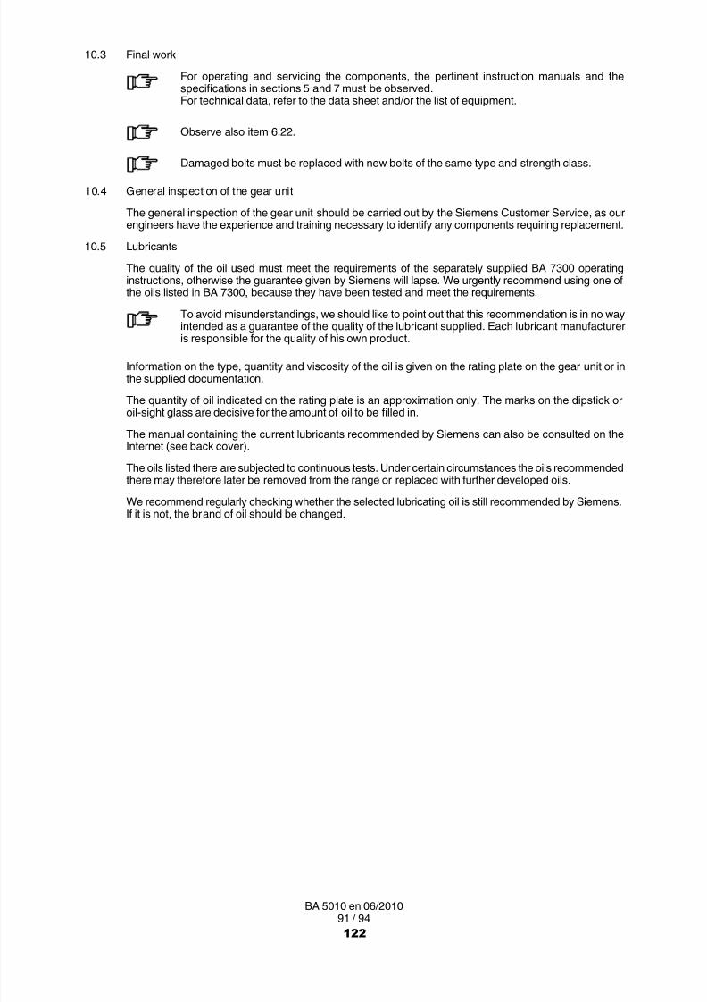
8/15/2019 r1_OF 71289_6 FF-AHF
http://slidepdf.com/reader/full/r1of-712896-ff-ahf 252/333
91 / 94BA 5010 en 06/2010
10.3 Final work
For operating and servicing the components, the pertinent instruction manuals and thespecifications in sections 5 and 7 must be observed.For technical data, refer to the data sheet and/or the list of equipment.
Observe also item 6.22.
Damaged bolts must be replaced with new bolts of the same type and strength class.
10.4 General inspection of the gear unit
The general inspection of the gear unit should be carried out by the Siemens Customer Service, as ourengineers have the experience and training necessary to identify any components requiring replacement.
10.5 Lubricants
The quality of the oil used must meet the requirements of the separately supplied BA 7300 operatinginstructions, otherwise the guarantee given by Siemens will lapse. We urgently recommend using one ofthe oils listed in BA 7300, because they have been tested and meet the requirements.
To avoid misunderstandings, we should like to point out that this recommendation is in no wayintended as a guarantee of the quality of the lubricant supplied. Each lubricant manufactureris responsible for the quality of his own product.
Information on the type, quantity and viscosity of the oil is given on the rating plate on the gear unit or inthe supplied documentation.
The quantity of oil indicated on the rating plate is an approximation only. The marks on the dipstick oroil sight glass are decisive for the amount of oil to be filled in.
The manual containing the current lubricants recommended by Siemens can also be consulted on theInternet (see back cover).
The oils listed there are subjected to continuous tests. Under certain circumstances the oils recommendedthere may therefore later be removed from the range or replaced with further developed oils.
We recommend regularly checking whether the selected lubricating oil is still recommended by Siemens.If it is not, the brand of oil should be changed.
122
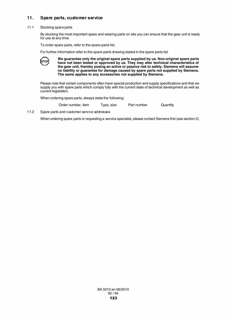
8/15/2019 r1_OF 71289_6 FF-AHF
http://slidepdf.com/reader/full/r1of-712896-ff-ahf 253/333
92 / 94BA 5010 en 06/2010
11. Spare parts, customer service
11.1 Stocking spare parts
By stocking the most important spare and wearing parts on site you can ensure that the gear unit is readyfor use at any time.
To order spare parts, refer to the spare-parts list.
For further information refer to the spare-parts drawing stated in the spare parts list.We guarantee only the original spare parts supplied by us. Non-original spare partshave not been tested or approved by us. They may alter technical characteristics ofthe gear unit, thereby posing an active or passive risk to safety. Siemens will assumeno liability or guarantee for damage caused by spare parts not supplied by Siemens.The same applies to any accessories not supplied by Siemens.
Please note that certain components often have special production and supply specifications and that wesupply you with spare parts which comply fully with the current state of technical development as well ascurrent legislation.
When ordering spare parts, always state the following:
Order number, item Type, size Part number Quantity
11.2 Spare parts and customer-service addresses
When ordering spare parts or requesting a service specialist, please contact Siemens first (see section 2).
123

8/15/2019 r1_OF 71289_6 FF-AHF
http://slidepdf.com/reader/full/r1of-712896-ff-ahf 254/333
93 / 94BA 5010 en 06/2010
12. Declarations
12.1 Declaration of incorporation
Declaration of Incorporationin accordance with Directive 2006/42/EC, Annex II 1 B
The manufacturer, Siemens AG, 46393 Bocholt, declares with regard to the partly completed machinery,
Gear UnitH.SH, H.VH, H.HH, H.DH, H.KH, H.FH, H.HM,H.DM, H.KM, H.FM, H.PH, B.SH, B.VH, B.HH,B.DH, B.KH, B.FH, B.HM, B.DM, B.KM, B.FM,
T.SH, T.HH, T.KH, T.DH, T.FHSizes 1 to 22
developed for driven machines in general engineering applications:
‐ The special technical documents described in Annex VII B have been prepared.
‐ The following basic health and safety requirements set out in Directive 2006/42/EC, Annex I,are applied and are satisfied:1.1, 1.1.2, 1.1.3, 1.1.5; 1.2.6; 1.3.1 ‐ 1.3.4, 1.3.6 ‐ 1.3.8.1; 1.4.1, 1.4.2.1;1.5.1, 1.5.2, 1.5.4 ‐ 1.5.11, 1.5.13; 1.6.1, 1.6.2; 1.7.1 ‐ 1.7.2, 1.7.4 1.7.4.3
‐ The partly completed machinery must not be put into service until it has been establishedthat the machinery into which the partly completed machinery is to be incorporatedhas been declared in conformity with the provisions of Directive 2006/42/EC, as appropriate.
‐ The manufacturer undertakes, in response to a reasoned request by the national authorities,to transmit in electronic form relevant information about the partly completed machinery.
‐ The person authorised to compile the relevant technical documentation is:Friedheim Schreier (Director ZGE Engineering)
Penig, 2010 06 01Friedheim Schreier(Director ZGE Engineering)
Penig, 2010 06 01Hans‐Hermann Olm(Director ZG Business Subsegment)
124

8/15/2019 r1_OF 71289_6 FF-AHF
http://slidepdf.com/reader/full/r1of-712896-ff-ahf 255/333
Siemens AGIndustry SectorMechanical DrivesAlfred-Flender-Straße 7746395 BocholtGERMANY
www.siemens.com/drive-technologies
Subject to modifications
© Siemens AG 2010
Further Information:"FLENDER gear units" on the Internetwww.siemens.com/gearunits
"FLENDER couplings" on the Internetwww.siemens.com/couplings
Service & Support:http://support.automation.siemens.com/WW/view/en/10803928/133300
Lubricants:http://support.automation.siemens.com/WW/view/en/42961591/133000
125

8/15/2019 r1_OF 71289_6 FF-AHF
http://slidepdf.com/reader/full/r1of-712896-ff-ahf 256/333
FLENDER supplies
Gear-unit lubricationforhelical gear units, bevel-gear units,bevel-helical gear-units, planetary-gear unitsand geared motors(with the exception of worm-geared motors)
Assembly and operating instructionsBA 7300 en 01/2012
126

8/15/2019 r1_OF 71289_6 FF-AHF
http://slidepdf.com/reader/full/r1of-712896-ff-ahf 257/333
2 / 21BA 7300 en 01/2012
Gear-unit lubrication
forhelical gear units, bevel-gear units,bevel-helical gear-units,planetary-gear units and geared motors(with the exception of worm-geared motors)
Assembly and operating instructionsTranslation of the original assembly and operating instructions
121212121212121212121Lubricating oils
12121212121212121212
12121212121212121212
12121212121212121212
12121212121212121212
12121212121212121212
12121212121212121212
12121212121212121212
121212121212121212124Documentation sheetfor oil change
121212121212121212123Check list foroil filling and oil change
121212121212121212122Lubricating greases
12121212121212121212
127

8/15/2019 r1_OF 71289_6 FF-AHF
http://slidepdf.com/reader/full/r1of-712896-ff-ahf 258/333
3 / 21BA 7300 en 01/2012
Notes and symbols in these assembly and operating instructions
Note: The term "Assembly and operating instructions" will in the following also be shortened to "instructions"or "manual".
Legal notes
Warning note conceptThis manual comprises notes which must be observed for your personal safety and for preventing material damage.Notes for your personal safety are marked with a warning triangle or an "Ex" symbol (when applyingDirective 94/9/EC), those only for preventing material damage with a "STOP" sign.
WARNING! Imminent explosion!
The notes indicated by this symbol are given to prevent explosion damage.Disregarding these notes may result in serious injury or death.
WARNING! Imminent personal injury!
The notes indicated by this symbol are given to prevent personal injury.Disregarding these notes may result in serious injury or death.
WARNING! Imminent damage to the product!
The notes indicated by this symbol are given to prevent damage to the product.Disregarding these notes may result in material damage.
NOTE!
The notes indicated by this symbol must be treated as general operating information .Disregarding these notes may result in undesirable results or conditions.
WARNING! Hot surfaces!
The notes indicated by this symbol are made to prevent risk of burns due to hot surfacesand must always be observed.Disregarding these notes may result in light or serious injury.
Where there is more than one hazard, the warning note for whichever hazard is the most serious is always used.If in a warning note a warning triangle is used to warn of possible personal injury, a warning of material damage maybe added to the same warning note.
Qualified personnelThe product or system to which these instructions relate may be handled only by persons qualified for the work
concerned and in accordance with the instructions relating to the work concerned, particularly the safety andwarning notes contained in those instructions. Qualified personnel must be specially trained and have theexperience necessary to recognise risks associated with these products or systems and to avoid possible hazards.
128

8/15/2019 r1_OF 71289_6 FF-AHF
http://slidepdf.com/reader/full/r1of-712896-ff-ahf 259/333
4 / 21BA 7300 en 01/2012
Intended use of Siemens productsObserve also the following:
Siemens products must be used only for the applications provided for in the catalogue and the relevanttechnical documentation. If products and components of other makes are used, they must berecommended or approved by Siemens. The faultfree, safe operation of the products calls for propertransport, proper storage, erection, assembly, installation, start-up, operation and maintenance. Thepermissible ambient conditions must be adhered to. Notes in the relevant documentations must be
observed.
TrademarksAll designations indicated with the registered industrial property mark ® are registered trademarks of Siemens AG.Other designations used in these instructions may be trademarks the use of which by third parties for their ownpurposes may infringe holders’ rights.
Exclusion of liabilityWe have checked the content of the instructions for compliance with the hard- and software described.Nevertheless, variances may occur, and so we can offer no warranty for complete agreement. The informationgiven in these instructions is regularly checked, and any necessary corrections are included in subsequent editions.
Symbols
Earth connection point Air relief point yellow
Oil-filling point yellow Oil-draining point white
Oil level red Oil level red
Oil level red Connection forvibration-monitoring device
Lubrication point red Apply grease
Lifting eye Eye bolt
Do not unscrew
Alignment surface, horizontal Alignment surface, vertical
These symbols indicate the oil-level checking procedure using the oil dipstick.
These symbols indicate that the oil dipstick must always be firmly screwed in.
129

8/15/2019 r1_OF 71289_6 FF-AHF
http://slidepdf.com/reader/full/r1of-712896-ff-ahf 260/333
5 / 21BA 7300 en 01/2012
Contents
1. Lubricating oils for helical gear units, bevel-gear units,bevel-helical gear-units, planetary-gear units and geared motors(with the exception of worm-geared motors) 6. . . . . . . . . . . . . . . . . . . . . . . . .
1.1 Oil groups and base oils 6. . . . . . . . . . . . . . . . . . . . . . . . . . . . . . . . . . . . . . . . . . . . . . . . . . . . . . . . . . . . .1.2 Quality, code numbers, approval lists 7. . . . . . . . . . . . . . . . . . . . . . . . . . . . . . . . . . . . . . . . . . . . . . . . . .
1.2.1 Required quality of the gear oils to be used 7. . . . . . . . . . . . . . . . . . . . . . . . . . . . . . . . . . . . . . . . . . . . .1.2.2 Code numbers, approval lists 8. . . . . . . . . . . . . . . . . . . . . . . . . . . . . . . . . . . . . . . . . . . . . . . . . . . . . . . . .1.3 Oil temperatures 9. . . . . . . . . . . . . . . . . . . . . . . . . . . . . . . . . . . . . . . . . . . . . . . . . . . . . . . . . . . . . . . . . . . .1.4 General service lives of oils 9. . . . . . . . . . . . . . . . . . . . . . . . . . . . . . . . . . . . . . . . . . . . . . . . . . . . . . . . . . .1.5 Information about initial filling and oil change 10. . . . . . . . . . . . . . . . . . . . . . . . . . . . . . . . . . . . . . . . . . . .1.6 Safety at work, environmental protection and general information 10. . . . . . . . . . . . . . . . . . . . . . . . . .1.7 Procedure for emptying the gear unit 11. . . . . . . . . . . . . . . . . . . . . . . . . . . . . . . . . . . . . . . . . . . . . . . . . . .1.7.1 Draining off the used oil filling 11. . . . . . . . . . . . . . . . . . . . . . . . . . . . . . . . . . . . . . . . . . . . . . . . . . . . . . . . .1.7.2 Checks and work to be done before refilling the gear unit 12. . . . . . . . . . . . . . . . . . . . . . . . . . . . . . . . .1.8 Putting in the fresh gear oil 13. . . . . . . . . . . . . . . . . . . . . . . . . . . . . . . . . . . . . . . . . . . . . . . . . . . . . . . . . . .1.9 Flushing procedure 14. . . . . . . . . . . . . . . . . . . . . . . . . . . . . . . . . . . . . . . . . . . . . . . . . . . . . . . . . . . . . . . . . .1.10 Procedure when changing the type of oil 15. . . . . . . . . . . . . . . . . . . . . . . . . . . . . . . . . . . . . . . . . . . . . . . .
1.11 Oil samples 15. . . . . . . . . . . . . . . . . . . . . . . . . . . . . . . . . . . . . . . . . . . . . . . . . . . . . . . . . . . . . . . . . . . . . . . .1.11.1 Taking an oil sample 15. . . . . . . . . . . . . . . . . . . . . . . . . . . . . . . . . . . . . . . . . . . . . . . . . . . . . . . . . . . . . . . . .1.11.2 Assessing the test results 16. . . . . . . . . . . . . . . . . . . . . . . . . . . . . . . . . . . . . . . . . . . . . . . . . . . . . . . . . . . .
2. Lubricating greases for gear units and rolling bearings 18. . . . . . . . . . . . . .
3. Check list for oil filling and oil change 19. . . . . . . . . . . . . . . . . . . . . . . . . . . . . . .
4. Documentation sheet for oil change 20. . . . . . . . . . . . . . . . . . . . . . . . . . . . . . . . .
130

8/15/2019 r1_OF 71289_6 FF-AHF
http://slidepdf.com/reader/full/r1of-712896-ff-ahf 261/333
6 / 21BA 7300 en 01/2012
1. Lubricating oils for helical gear units, bevel-gear units, bevel-helicalgear-units, planetary-gear units and geared motors (with the exception ofworm-geared motors)
These assembly and operating instructions do not apply to gear units made byWINERGY AG and Flender Graffenstaden S.A.S. These plants provide differentinstructions.
For "FLENDER gear units" not referred to in these assembly and operating instructions thefollowing manuals will apply:
Ship’s gearboxes: BA 7301Worm-gear unit: BA 7303
1.1 Oil groups and base oils
Siemens Mechanical Drives (MD), Bocholt, distinguishes between the following oil groups in regard togear oils for FLENDER gears:
• Standard oils
• Biologically degradable oils (also called "BIO" for short)
• Physiologically safe oils approved in accordance with NSF-H1 (also called "PHY" for short)
The tested and recommended gear oils can be manufactured on the basis of the following four base oils:
• Mineral oils
• Poly α olefins (also called "PAO" for short)
• Polyglykole (also called "PG" or "PAG" for short)
• synthetic esters
Theoretically all four base oil types may occur in each oil group.
131

8/15/2019 r1_OF 71289_6 FF-AHF
http://slidepdf.com/reader/full/r1of-712896-ff-ahf 262/333
7 / 21BA 7300 en 01/2012
1.2 Quality, code numbers, approval lists
1.2.1 Required quality of the gear oils to be used
For "FLENDER gear units", Siemens approves only CLP quality oils which contain constituentsto DIN 51517-3 for improvement of corrosion prevention and resistance to ageing and which reduce wearin mixed-friction areas. The oils must have passed the following tests (see also - Specification of gear oilapprovals for FLENDER gear units):
• Scuffing resistance in the FZG-testto DIN ISO 14635-1 under the A/8.3/90 test conditions Fail stage > 12
• FE-8 rolling-bearing test to DIN 51819-3under the D-7.5/80-80 test conditions
Rolling-element wear < 30 mgCage wear: state value
• Resistance to grey staining to FVA 54 I-IV GF fail stage ≥ 10Resistance to grey stainingGFT = high
• Flender foam test – Increase in total volume1 minute after switching off ≤ 15 %
– Increase in oil-air dispersion5 minutes after switching off ≤ 10 %
• Static and dynamic ”FLENDER-Freudenberg test”for shaft sealing rings
Approval by Messrs. Freudenberg
• Compatibility with liquid seals Approval by Messrs. Loctite
• "FLENDER-Mäder-Farbtest" (colour test) Approval by Messrs. Mäder
Oil group, base oil and viscosity class as stated in the specifications on the ratingplates and information in the gear unit documentation must be adhered to!Failure to do so will result in invalidation of the guarantee.
If oil filters are used in the system the oil supplier should be requested to confirm that
the filters do not negatively affect the characteristics of the oil.The unapproved use of oils which do not comply with the above quality requirementswill invalidate the Siemens product guarantee obligation. In addition adherence to theinstructions given in these operating instructions is conditional for any claims underwarranty.
Deviations are permitted only after consultation with Siemens!
If the operating conditions have been subsequently modified and differ from thosestated in the customer’s order, the gear oil to be used must be approved by Siemensin writing.
132

8/15/2019 r1_OF 71289_6 FF-AHF
http://slidepdf.com/reader/full/r1of-712896-ff-ahf 263/333
8 / 21BA 7300 en 01/2012
1.2.2 Code numbers, approval lists
To help its customers Siemens MD, Bocholt, has grouped oils in approval lists. The above-mentioned testresults have been verified to Siemens for these oils by the oil manufacturers. Also worldwide adherenceto the characteristics, features and minimum requirements required by Siemens has been guaranteed bythe oil manufacturers.
Assignment of the approved oils to the oil groups, the base oils and the viscosities is indicatedby code numbers in the approval lists.
Code number A13 indicates e.g. all standard mineral oils with the viscosity ISO VG 460.
Table 1: Code numbers of lubricant assigment, standard oilsCLP oils for "FLENDER" helical-, bevel- and planetary-gear units and geared motors
ISO VG: 100 150 220 320 460 680 1000
Mineral oils A 17 A 16 A 15 A 14 A 13 A 12 A 11
Polyglycols A 27 A 26 A 25 A 24 A 23 A 22 A 21
Poly α olefins A 37 A 36 A 35 A 34 A 33 A 32 A 31
Table 2: Code numbers of lubricant assigment, biologically degradable oils
CLP oils for "FLENDER" helical-, bevel- and planetary-gear units and geared motors
ISO VG: 100 150 220 320 460 680 1000
Synthetic esters A 47 A 46 A 45 A 44 A 43 A 42 A 41
Table 3: Code numbers of lubricant assigment, physiologically safe oilsCLP oils for "FLENDER" helical-, bevel- and planetary-gear units and geared motors
ISO VG: 100 150 220 320 460 680 1000
Polyglycols A 57 A 56 A 55 A 54 A 53 A 52 A 51
Poly α olefins A 67 A 66 A 65 A 64 A 63 A 62 A 61
Table 4: Code numbers of lubricant assigmentRolling-bearing greases for use in "FLENDER gear units"
NLGI class: 2 3
Mineral oil base H 14 H 13
The approval lists "T 7300" with the current gear-oil recommendations for "FLENDER gearunits" are available as "FAQ" on the Internet under the following link:
http://support.automation.siemens.com/WW/view/en/44231658
We recommend checking before any oil change whether the chosen lubricant is still approved
by Siemens.
The approval of these gear oils for use in FLENDER gear units and their consequent inclusion in therelevant lists does not mean that Siemens is liable for the suitability and quality of the oils. Nor is Siemensliable for any damage caused to FLENDER gear units by the use of these gear oils.Each gear-oil manufacturer is always responsible for the suitability and quality of his own product.
133
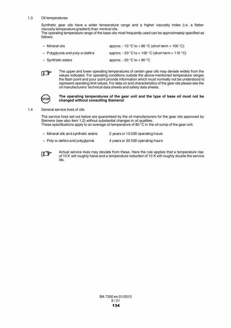
8/15/2019 r1_OF 71289_6 FF-AHF
http://slidepdf.com/reader/full/r1of-712896-ff-ahf 264/333
9 / 21BA 7300 en 01/2012
1.3 Oil temperatures
Synthetic gear oils have a wider temperature range and a higher viscosity index (i.e. a flatterviscosity-temperature gradient) than mineral oils.The operating temperature range of the base oils most frequently used can be approximately specified asfollows:
─ Mineral oils approx. - 10 °C to + 90 °C (short term + 100 °C)
─ Polyglycols and poly α olefins approx. - 20 °C to + 100 °C (short term + 110 °C) ─ Synthetic esters approx. - 20 °C to + 90 °C
The upper and lower operating temperatures of certain gear oils may deviate widely from thevalues indicated. For operating conditions outside the above-mentioned temperature rangesthe flash point and pour point provide information which must normally not be understood torepresent operating limit values. For data on and characteristics of the gear oils please see theoil manufacturers’ technical data sheets and safety data sheets.
The operating temperatures of the gear unit and the type of base oil must not bechanged without consulting Siemens!
1.4 General service lives of oilsThe service lives set out below are guaranteed by the oil manufacturers for the gear oils approved bySiemens (see also item 1.2) without substantial changes in oil qualities.These specifications apply to an average oil temperature of 80 °C in the oil sump of the gear unit.
─ Mineral oils and synthetic esters 2 years or 10 000 operating hours
─ Poly α olefins and polyglycols 4 years or 20 000 operating hours
Actual service lives may deviate from these. Here the rule applies that a temperature riseof 10 K will roughly halve and a temperature reduction of 10 K will roughly double the servicelife.
134

8/15/2019 r1_OF 71289_6 FF-AHF
http://slidepdf.com/reader/full/r1of-712896-ff-ahf 265/333
10 / 21BA 7300 en 01/2012
1.5 Information about initial filling and oil change
The purity level of the gear oil affects the operational reliability and service life of the oil and the gear unit.Accordingly, care should be taken to use only clean oil in the gear unit. For initial filling and oil changes thesupplementary specifications, if any, in the gear unit instructions must also be observed.
Careful initial filling and careful oil changing contribute considerably to an increase in the operationalreliability and service life of both the gear unit and the oil.
When putting in and changing oil no impurities such as foreign bodies, water or otherliquids must be allowed to get into the interior of the gear unit.
In the case of large quantities of oil it is recommended to carry out an oil analysis to determinewhether the oil needs to be cleaned or changed.
For recording purposes it is recommended to use table 7 (see section 4).
1.6 Safety at work, environmental protection and general information
All work carried out on the gear unit must be carried out carefully and by qualified personnel only(see also "Qualified Personnel" on page 3 of these instructions).
The following regulations and documents must be adhered to:
─ Regulations for safety at work and environmental protection.
─ Regulations for the disposal of used oil.
Gear oils are recyclable materials. Local legal requirements must be observed when disposingof them.
─ Product data sheets for the oils used, including flushing oil, if necessary
─ Safety data sheets for the oils and aids used
─ Operating and maintenance instructions for the gear units scheduled for initial filling or oil change,including the oil supply system
─ Documentation sheet for oil change (see table 7)
The following preparations must be made on the gear unit:
─ Suitable body protection must be used (skin care media, gloves, work shoes, safety glasses, earprotectors, etc.).
─ Sufficient space and cleanliness in the work place must be ensured.
─ Provision of following aids and parts:
─ suitable oil-collecting and/or extraction equipment of a sufficient size
─ suitable, cleaned equipment and containers for oil sampling (see item 1.11).
─ suitable equipment for marking the oil sample
─ sufficient quantity of clean flushing oil (if necessary)
─ correct type and sufficient quantity of fresh oil for refilling the gear unit
─ cleaned filling system and further aids, including filling filters
─ fresh seals (if necessary)
─ oil binding and cleaning media
─ lintfree, clean cleaning cloths in sufficient quantity
For initial filling the procedure set out in item 1.8 must be adhered to.
135

8/15/2019 r1_OF 71289_6 FF-AHF
http://slidepdf.com/reader/full/r1of-712896-ff-ahf 266/333
11 / 21BA 7300 en 01/2012
1.7 Procedure for emptying the gear unit
It is recommended to use the check list in table 6 as an aid.
Before the oil is changed, a sample of the oil still warm from operation should be taken from the gear unitin an adequate manner and documented and kept for later reference (see item 1.11).
1.7.1 Draining off the used oil filling
─ Note information given in the operating instructions for draining off the used oil. This also appliesparticularly to central lubricating systems and other oil supply equipment. If no relevant information isgiven, the lowest possible point must be used to drain off or suck out the oil.
─ Shut down gear unit and ensure that it cannot be started up.
─ Check and record oil level.
An oil level above the max mark may indicate that a foreign liquid (e.g. water) has got in.An oil level below the min mark may indicate that there is a leak. Both conditions must be ratedas a fault and may result in damage to the gear unit. The cause must be found and, if necessary,rectified before refilling!
After shutting off the gear unit the oil should be changed as soon as possible to prevent any
solid matter from settling.Should this not be possible, the gear unit must be run again for a short while before drainingoff the oil.The oil should as far as possible be drained off while it is still hot (approx. 50 °C).
Risk of scalding from escaping hot oil!
─ Visual check for possible leakage. If there is leakage, the cause must be found and rectified beforerefilling.
─ Before draining off or sucking out the oil open all vent holes provided.
─ Position the oil collector under the oil drain.
─ Drain off or suck out oil and, if necessary, also empty all oil pockets.
Risk of scalding from escaping hot oil!Open drain carefully.
─ The oil draining off must be collected in accordance with regulations. If necessary, ancillary units(such as oil supply systems, filters) and pipework must likewise be emptied.
─ On gear units with an oil circulation system and on oil supply systems the oil-conducting system mustbe emptied in accordance with the manufacturer’s instructions in the operating and maintenanceinstructions.
Any spilled oil must be immediately bound with oil binding material and disposed ofin accordance with regulations!
136

8/15/2019 r1_OF 71289_6 FF-AHF
http://slidepdf.com/reader/full/r1of-712896-ff-ahf 267/333
12 / 21BA 7300 en 01/2012
1.7.2 Checks and work to be done before refilling the gear unit
─ The quantity of oil drained off must be compared with the manufacturer’s rated quantity. If despitea correct oil level the quantity is considerably less than the rated quantity, it must be assumed that thereare considerable quantities of used oil remaining in the gear unit and/or the ancillary units.
In this case the flushing procedure set out in item 1.9 must be followed.
─ The oil drained off must be checked visually (appearance, colour, impurities, etc).
─ If there is serious contamination (e.g. by water, metal particles, sludge), a specialist (preferablya Siemens specialist) must be called in to trace the cause.
The lubricating oil system must then be thoroughly flushed out before refilling (see item 1.9).
─ Oil drain plugs with a magnet or magnetic extractors provided must be inspected for and freed ofabraded metal. If a large amount of abraded metal is suspected, a specialist (preferably a Siemensspecialist) must be called in to trace the cause.
─ On gears with inspection holes the interior of the gear unit must be checked for deposits and the teethand bearings checked for damage. Any damage must be repaired. If there are heavy deposits or otherimpurities, the flushing procedure set out in item 1.9 must be followed. If it is evident that the impuritiescannot be removed by flushing alone, they must be removed mechanically. Residues may be removedfrom storage containers by using a rubber scraper.
Before opening inspection covers on gear units the area around the inspection hole must bethoroughly cleaned to prevent dirt from getting into the interior of the gear unit from outsidewhen the cover is opened.
─ Oil filters and seals provided must be cleaned or changed in accordance with regulations.
─ The used oil must be disposed of in accordance with regulations.
Certain synthetic oils or impurities may have to be disposed of by different means from that fornormal used oils. The oil data sheets must be observed.
137

8/15/2019 r1_OF 71289_6 FF-AHF
http://slidepdf.com/reader/full/r1of-712896-ff-ahf 268/333
13 / 21BA 7300 en 01/2012
1.8 Putting in the fresh gear oil
For initial filling it is recommended to use table 6, "Oil-change check list", from point 27 on asan aid.
For oil changing the gear unit must be filled only with fresh oil of the type and makepreviously used. If necessary, the specifications for the required purity class in theoperating instructions must be observed. The make of oil or even the type of base oilmust not be changed without very good reasons. If the oils previously used and those
subsequently used are incompatible, a flushing procedure must be followed(see item 1.9).
It is recommended to keep a sample of the fresh oil before filling as a reference sample for latercomparison.
The following steps must be carried out:
─ Clean the seats of the vent covers, drain plugs, etc).
─ If necessary, fit previously new seals on previously opened vent covers, drain plugs, etc., and close.
─ If necessary, a flushing procedure must be followed at this point. Unless otherwise prescribed by thegear unit and/or oil manufacturer, the procedure as set out in item 1.9 is recommended.
─ Check fresh oil visually for the following parameters:
─ Homogeneity
─ Freedom from solid impurities and water (clouding)
─ Colour and appearance in compliance with the oil manufacturer’s product-specific data
─ Put in fresh oil up to the prescribed fill level.
The oil quantity specified on the rating plates is only a guide value. Decisive for thequantity of oil to be put in are the marks on the oil dipstick or the other oil levelindication systems.
─ Fresh oil may be contaminated. The oil should therefore be put in through a filter as set out in theoperating and maintenance instructions. If no specifications are available for this, filling filters with afilter mesh of 10 µm have proved highly effective. It is recommended to preheat the oil tobetween 35 and 40 °C. It sometimes also suffices to store the oil to be used to fill the gear unit with forapprox. 2 to 3 days in a room at a temperature of approx. 25 °C before putting it in.
─ If necessary, also fill ancillary units (oil systems, filters, etc.) and pipework.
─ After a short operating time (approx. 10 minutes) and a rest time of at least 15 minutes the oil level mustbe rechecked and, if necessary, more oil put in or oil drained off.
It is recommended to take an oil sample approx. 5 operating hours after changing the oil andto record and keep it for later checking.
─ Fill out and keep the documentation sheet for the oil change (see table 7).
─ After a week at most check the oil filter (if provided) for deposits and, if necessary, clean or replace it.Impurities still remaining in the system may have dissolved and may be blocking the filters.
138

8/15/2019 r1_OF 71289_6 FF-AHF
http://slidepdf.com/reader/full/r1of-712896-ff-ahf 269/333
14 / 21BA 7300 en 01/2012
1.9 Flushing procedure
When changing the oil make, particularly the base oil type, if the gear oil put in is badlycontaminated or major repairs have been carried out on the gear unit, a flushingprocedure is necessary before finally filling the system with the operating oil.
If necessary, specifications for flushing included in the gear unit operating instructions must be adheredto. The following procedure is given only as an example and must be adjusted to suit local conditions.
The described procedure must be scheduled in addition to the activities specified for oilchanging and must be integrated at the appropriate point in the procedure plan.
─ Ensure that gear unit cannot be started up.
─ To prevent incompatibilities the same type of lubricating oil as that to be used later should be used forflushing. To achieve a better flushing and dissolving effect a lower viscosity level of the same type ofoil may have to be selected. Here the lubrication requirements of all component assemblies, includingthe pumps, must be taken into consideration.
The use of special cleaning or flushing oils is possible and is sometimes unavoidable.
If special cleaning or flushing oils are used, prior agreement with the oil supplier andSiemens is necessary.
─ As with oil changing for the fresh oil as set out in item 1.8, the flushing oil must be visually checkedbefore use.
─ The system must be filled with the oil designated for flushing until a short run without load or in thepart-load range is possible without disruptions
Heated flushing oil improves the flushing action and shortens flushing time. Because of the riskof scalding 50 °C must not be exceeded.
Risk of scalding from escaping hot oil!
─ When filling with flushing oil any ancillary units provided must be taken into consideration. If necessary,these should be filled separately and emptied again after the flushing run.
─ The gear unit must be operated for a short time with the flushing oil filling to ensure that it is mixedintensively with the residual oil remaining in the system and to as far as possible dissolve impurities.If no flushing time is specified in the operating and maintenance instructions, at least 10 to 60 minutesare recommended. The greater the operating oil quantity and the worse the contamination, the longerthe time taken for flushing should be.
It is recommended to clean the flushing oil in the bypass flow during the flushing operation.
─ The flushing oil must then be drained off. The procedure is identical to that followed for draining off theused oil (see item 1.7.1).
─ The flushing oil must be visually checked. If there are still unacceptable impurities in the oil and/or thegear unit, this flushing procedure must be repeated until the desired result is achieved.
Depending on its condition, the flushing oil may be cleaned and re-used as flushing oil or must bedisposed of.
The flushing oil must not be used as operating oil.
139

8/15/2019 r1_OF 71289_6 FF-AHF
http://slidepdf.com/reader/full/r1of-712896-ff-ahf 270/333
15 / 21BA 7300 en 01/2012
1.10 Procedure when changing the type of oil
The type of oil should be changed in exceptional cases only for important reasons. Whenchanging to another base oil type or to an oil with very different additive technology,incompatibilities may result.
Ultimately only oil manufacturers can judge the compatibility of different gear oils. It is thereforeurgently advisable to involve them in the decision process.
When changing to a lubricating oil with another base oil type or with different additivetechnology, the entire system must be thoroughly cleaned and flushed after drainingoff the used oil (see item 1.9). In this case the flushing oil may be used at most a secondtime to flush out the same gear unit. The flushing oil must then be disposed of.
When changing to a new type of oil of similar composition a flushing procedure as set out initem 1.9 is likewise to be recommended.
The following points must be additionally observed when changing the type of base oil:
• The compatibility of the new oil with other gear unit components, e.g. sealing materials or varnishes andpaints, must be checked. To be recommended are the oils approved by Siemens (see item 1.2).
• Cavitation problems may arise with oils of a higher density. Larger suction line cross-sections may berequired.
1.11 Oil samples
1.11.1 Taking an oil sample
• For reference purposes a fresh oil sample of the operating lubricating oil must, before the gear unit isfilled, be analysed by the laboratory, in which the samples of the used oil are also to be inspected later.The test results must be recorded and kept for later comparisons.
• The oil sample must be taken so that it is representative. A precondition for this is that the oil filling isas homogeneous as possible. For this reason the oil sample should be taken, if possible, while the gearunit is running, when the oil is still warm from operation, from the same point and always by the samemethod and by the same specialist. If the gear unit has to be stationary, the sample must be taken nolater than 10 minutes after the gear unit is taken out of operation. In this way demixture or depositionis largely avoided.
• When choosing the sampling point, it is important that the agitated oil is accessible. Places where theoil has not been agitated or samples of the immediate oil surface or from the bottom must be avoided.If there is a filter in the oil circuit, the sample must be taken from a point upstream of the filter.
• The sampling point must be cleaned before the oil sample is taken. While the sample is being taken,moisture (water) and contaminants (e.g. dust) from the environment must be prevented from entering.
• The required size of the sample is determined by the required scope of the analysis. In case of doubtit is recommended that the analysing laboratory be consulted. 250 ml are normally sufficient for routineanalyses. The sample containers must be suitable, clean, dry vessels with tight closures (see standardISO 3722: Hydraulic fluid power – Fluid sample containers – Qualifying and controlling cleaningmethods <4>). They must be resistant to the sample material up to operating oil temperature.Transparent and tightly sealable wide-neck bottles of glass or HD-PE have proved suitable. If it shouldbe necessary to clean the sample containers, it is recommended that they be thoroughly flushed outseveral times on site with the operating oil. The flushing oil must then be disposed of.
Milk, wine, beer, mineral-water bottles or other containers used to store foodstuffs must not beused as sample containers, even if they have been properly cleaned and marked.
140
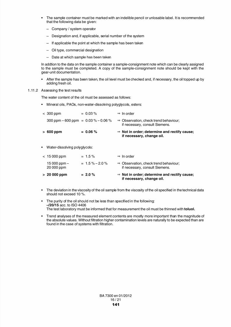
8/15/2019 r1_OF 71289_6 FF-AHF
http://slidepdf.com/reader/full/r1of-712896-ff-ahf 271/333

8/15/2019 r1_OF 71289_6 FF-AHF
http://slidepdf.com/reader/full/r1of-712896-ff-ahf 272/333
17 / 21BA 7300 en 01/2012
Table 5: Possible cause of changes in test results (trend analysis)
Change Possible causes
Viscosity ↑ ─ Short-chain constituents volatilised
─ High-viscosity foreign fluids / greases got in
Viscosity ↓
─ Long-chain constituents cracked
─ Viscosity-index improvers cut or used up ─ Low-viscosity foreign fluids got in
TAN (NZ) ↑ ─ Oil aged, acids produced
PQ‐Index ↑ ─ Wear caused by magnetisable substances (particularly Fe)
Fe ↑ ─ Wear and oxidation on gears and rolling bearings, corrosion on housing
Cr ↑ ─ Wear on rolling bearings and gears
Ni ↑ ─ Wear on rolling bearings and gears
Al ↑ ─ Wear on oil-pump bearings
Cu ↑ ─ Wear on rolling-bearing cages and slide bearingsZn ↑ ─ Washed out of priming coat
Zn ↓ ─ Additive with Zn content used up
Sn ↑ ─ Wear on slide bearings
Si ↑ ─ Contamination from outside (dust)
Si ↓ ─ Anti-foaming additive used up
Ca ↑ ─ Contamination from outside (e.g. chalk dust)
Oil clouded ─ Contamination from water and/or other foreign fluids (including oils)
Oil darker ─ Oil aged
The oil supplier must decide about the further usability of the oil. He must guaranteethat the properties of the oil conform to the Siemens specification.
142

8/15/2019 r1_OF 71289_6 FF-AHF
http://slidepdf.com/reader/full/r1of-712896-ff-ahf 273/333
18 / 21BA 7300 en 01/2012
2. Lubricating greases for gear units and rolling bearings
For special gear unit applications, grease lubrication of the bearings may be necessary.
Greases may be used only if their use is specified in the operating instructions for thegear unit. The relubrication periods must be adhered to.
As well as lubrication, rolling bearing greases are used for the special sealing of bearing points, e.g. withvertical gear-unit connection shafts or against environmental action such as dust or water spray.
In closed gear units with internal oil lubrication the gear oil must not be allowed to mix withbearing grease.
The approval lists "T 7300" with the current grease recommendations for "FLENDER gearunits" are available as "FAQ" on the Internet under the following link:
http://support.automation.siemens.com/WW/view/en/44231658
When using greases, we recommend checking every year whether the chosen lubricant is stillapproved by Siemens.
143

8/15/2019 r1_OF 71289_6 FF-AHF
http://slidepdf.com/reader/full/r1of-712896-ff-ahf 274/333
19 / 21BA 7300 en 01/2012
3. Check list for oil filling and oil change
Table 6: Oil change check list
1 Oil change record ready for completion? □ 21 Gear unit internal parts inspected for damage,repaired or replaced (if necessary)?
□
2 Sufficient fresh oil available? □ 22 Gear unit and oil supply system with pipeworkflushed out (if necessary)?
□
3 Sufficiently large oil collector and used oilreceptacle(s) available?
□ 23 Oil filter cleaned or replaced(if necessary)?
□
4 Sufficient oil binding and cleaning materialsavailable?
□ 24 Seals changed? □
5 Sufficient room available for oil change? □ 25 Opened vent and drain points closed again? □
6 Oil samples (used and fresh oil) taken andstored?
□ 26 Cause(s) of leaks removed (see item 10)? □
7 Protective clothing (glasses, gloves, etc.)available and used?
□ 27 Fresh oil visually checked? □
8 Oil change by specialist personnel? □ 28 Oil filling hole(s) opened? □
9 Gear unit and/or oil supply systemmanufacturers’ maintenance instructions read?
□ 29 Fresh oil put in through filter up to mark on theoil level check point?
□
10 Leaks in the drive and/or output recorded aftervisual check?
□ 30 Oil filling hole closed? □
11 Used oil at a temperature of between 30 and50 °C and drive started?
□ 31 Drive started and run for a short while(approx. 10 minutes)?
□
12 Drive shut down and prevented fromrestarting?
□ 32 Oil level checked(after min. 15 minutes rest time)?
□
13 Vent hole opened? □ 33 Oil topped up or drained off until the oil level iscorrect (if necessary)?
□
14 Oil collector placed under the oil drain? □ 34 Oil change record completed? □
15 Drain opened carefully?Caution - risk of scalding!
□ 35 Sample of used oil checked? □
16 Used oil completely drained off? □ 36 Used oil correctly disposed of? □
17 Ancillary units, oil pockets and pipeworkemptied (if any)?
□ 37 Sample of new operating oil taken afterapprox. 5 hours and stored(for checking when changing type of oil)?
□
18 Spilled oil immediately bound with suitablematerial?
□ 38 Binding material and cleaning cloths correctlydisposed of?
□
19 Used oil assessed and recorded? □ 39 Drive re-started? □20 Gear unit and other units thoroughly cleaned? □ 40 Filter checked and cleaned or replaced
(after one week’s operation at most)?□
144

8/15/2019 r1_OF 71289_6 FF-AHF
http://slidepdf.com/reader/full/r1of-712896-ff-ahf 275/333
20 / 21BA 7300 en 01/2012
4. Documentation sheet for oil change
Table 7: Oil change oil filling record
Oil change oil filling record
System: . . . . . . . . . . . . . . . . . . . . . . . . . . . . . . . . . . . . . . . . . . . . . . . . . . . . . . . . . . . . Gear unit: . . . . . . . . . . . . . . . . . . . . . . .
Date: . . . . . . . . . . . . . . . . . . . . . . . . . . Operating hours: . . . . . . . . . . . . . . . . . Last oil change . . . . . . . . . . . . . . . . . . .
Oil to be usedaccording to rating plate: . . . . . . . . . . . . . . . . . . . . . . . . . . . . . . . . . . . . . . . . . . . . .
Quantityaccording to rating plate: . . . . . . . . . .
Condition before oil change
Designation of oil: . . . . . . . . . . . . . . . . . . . . . . . . . . . Oil level: . . . . . . . . . . . . . . . . . . . . . . . . . . . . . . . . . . . . . . . . . . . . . . . .
Gear unit/oil supply system leaktight? yes □ no □ Filter dirty? yes □ no □
Operating temperature: °C. . . . . . . . . . .
Other noticeable features: . . . . . . . . . . . . . . . . . . . . . . . . . . . . . . . . . . . . . . . . . . . . . . . . . . . . . . . . . . . . . . . . . . . . . . . . . . . . . . .
. . . . . . . . . . . . . . . . . . . . . . . . . . . . . . . . . . . . . . . . . . . . . . . . . . . . . . . . . . . . . . . . . . . . . . . . . . . . . . . . . . . . . . . . . . . . . . . . . . . . . . .
Used oil
Identification mark of used oil sample: . . . . . . . . . . . . . . . . . . . . . . . . . . . . . . . . . . Laboratory number: . . . . . . . . . . . . . . .
Quantity: . . . . . . . . . . . . . . . . . . . . . . . .
Result of visual check of oil: . . . . . . . . . . . . . . . . . . . . . . . . . . . . . . . . . . . . . . . . . . . . . . . . . . . . . . . . . . . . . . . . . . . . . . . . . . . . . .
Gear unit / oil supply system
Deposits? yes □ no □
Result of visual check of oil: . . . . . . . . . . . . . . . . . . . . . . . . . . . . . . . . . . . . . . . . . . . . . . . . . . . . . . . . . . . . . . . . . . . . . . . . . . . . . .
Fresh oil
Designation of oil: . . . . . . . . . . . . . . . . . . . . . . . . . . . . . . . . . . . . . . . . . . . . . . . . . . . . . . . . . . . . . . . . . . . . . . . . . . . . . . . . . . . . . .
Designation of fresh oil sample: . . . . . . . . . . . . . . . . . . . . . . . . . . . . . . . . . . . . . . Laboratory number: . . . . . . . . . . . . . . .
Filtered during filling? yes □ no □ Filter mesh: µm. . . . . . Quantity put in: . . . . . . . . . . . . . . . . . . .
Result of visual check of oil: . . . . . . . . . . . . . . . . . . . . . . . . . . . . . . . . . . . . . . . . . . . . . . . . . . . . . . . . . . . . . . . . . . . . . . . . . . . . . .
Was/were the gear unit and/or the oil supply system flushed before being filled with fresh oil?
yes □ with . . . . . . . . . . . . . . . . . . . . . . . . . . . . . . . . . . . . . . . . . . . . . . . . . . . . . . . . . . . . . . . . . . . . . . . . . . . no □
Noticeable features (if applicable): . . . . . . . . . . . . . . . . . . . . . . . . . . . . . . . . . . . . . . . . . . . . . . . . . . . . . . . . . . . . . . . . . . . . . . . .
. . . . . . . . . . . . . . . . . . . . . . . . . . . . . . . . . . . . . . . . . . . . . . . . . . . . . . . . . . . . . . . . . . . . . . . . . . . . . . . . . . . . . . . . . . . . . . . . . . . . . . .
Designation of 5-hour operating oil sample: . . . . . . . . . . . . . . . . . . . . . . . . . . . . Laboratory number: . . . . . . . . . . . . . . .
Name of recorder: . . . . . . . . . . . . . . . . . . . . . . . . . . . . . . . . . . . . . . . . . . . . . . . . . . . Department: . . . . . . . . . . . . . . . . . . . . .
Date: . . . . . . . . . . . . . . . . . . . . . . . . . . Signature:
145

8/15/2019 r1_OF 71289_6 FF-AHF
http://slidepdf.com/reader/full/r1of-712896-ff-ahf 276/333
Siemens AGIndustry SectorMechanical DrivesAlfred-Flender-Straße 7746395 BocholtGERMANY
www.siemens.com/drive-technologies
Subject to modifications
© Siemens AG 2012
Further Information:
"FLENDER gear units" on the Internetwww.siemens.com/gearunits
"FLENDER couplings" on the Internetwww.siemens.com/couplings
Service & Support:http://support.automation.siemens.com/WW/view/en/10803928/133300
Lubricants:http://support.automation.siemens.com/WW/view/en/42961591/133000
146

8/15/2019 r1_OF 71289_6 FF-AHF
http://slidepdf.com/reader/full/r1of-712896-ff-ahf 277/333
Weir Minerals Latin AmericaVulco Perú S.A.
ExcellentMineralsSolutions
Manual de Operaciones y Mantenimiento
AcoplesCouplings
Av. Separadora Industrial 2201Ate – Lima, Perú
T: +51 (1) 6187575E: [email protected]
W: www.weirminerals.com

8/15/2019 r1_OF 71289_6 FF-AHF
http://slidepdf.com/reader/full/r1of-712896-ff-ahf 278/333
FLENDER couplings
FLENDER N-EUPEX® andFLENDER N-EUPEX-DS®couplingsTypes A, Band ADS, BDS
Operating instructionsBA 3100 en 08/2011
173

8/15/2019 r1_OF 71289_6 FF-AHF
http://slidepdf.com/reader/full/r1of-712896-ff-ahf 279/333
2 / 24BA 3100 en 08/2011
FLENDER N-EUPEX® andFLENDER N-EUPEX-DS®couplings
Types A, Band ADS, BDS
Operating instructionsTranslation of the original operating instructions
Technical data
Declarations
Stocking spare parts
Maintenanceand repair
Faults, causesand remedy
Start upand operation
Fitting
Notes
1
8
7
6
5
4
3
2
174

8/15/2019 r1_OF 71289_6 FF-AHF
http://slidepdf.com/reader/full/r1of-712896-ff-ahf 280/333
3 / 24BA 3100 en 08/2011
Notes and symbols in these operating instructions
Note: The term "Operating instructions" will in the following also be shortened to "instructions" or "manual".
Legal notes
Warning note conceptThis manual comprises notes which must be observed for your personal safety and for preventing material damage.Notes for your personal safety are marked with a warning triangle or an "Ex" symbol (when applyingDirective 94/9/EC), those only for preventing material damage with a "STOP" sign.
WARNING! Imminent explosion!
The notes indicated by this symbol are given to prevent explosion damage.Disregarding these notes may result in serious injury or death.
WARNING! Imminent personal injury!
The notes indicated by this symbol are given to prevent personal injury.Disregarding these notes may result in serious injury or death.
WARNING! Imminent damage to the product!
The notes indicated by this symbol are given to prevent damage to the product.Disregarding these notes may result in material damage.
NOTE!
The notes indicated by this symbol must be treated as general operating information .Disregarding these notes may result in undesirable results or conditions.
WARNING! Hot surfaces!
The notes indicated by this symbol are made to prevent risk of burns due to hot surfacesand must always be observed.Disregarding these notes may result in light or serious injury.
Where there is more than one hazard, the warning note for whichever hazard is the most serious is always used.If in a warning note a warning triangle is used to warn of possible personal injury, a warning of material damage maybe added to the same warning note.
Qualified personnelThe product or system to which these instructions relate may be handled only by persons qualified for the workconcerned and in accordance with the instructions relating to the work concerned, particularly the safety and
warning notes contained in those instructions. Qualified personnel must be specially trained and have theexperience necessary to recognise risks associated with these products or systems and to avoid possible hazards.
175
8/15/2019 r1_OF 71289_6 FF-AHF
http://slidepdf.com/reader/full/r1of-712896-ff-ahf 281/333
4 / 24BA 3100 en 08/2011
Intended use of Siemens productsObserve also the following:
Siemens products must be used only for the applications provided for in the catalogue and the relevanttechnical documentation. If products and components of other makes are used, they must berecommended or approved by Siemens. The faultfree, safe operation of the products calls for propertransport, proper storage, erection, assembly, installation, start-up, operation and maintenance. Thepermissible ambient conditions must be adhered to. Notes in the relevant documentations must be
observed.
TrademarksAll designations indicated with the registered industrial property mark ® are registered trademarks of Siemens AG.Other designations used in these instructions may be trademarks the use of which by third parties for their ownpurposes may infringe holders’ rights.
Exclusion of liabilityWe have checked the content of the instructions for compliance with the hard- and software described.Nevertheless, variances may occur, and so we can offer no warranty for complete agreement. The informationgiven in these instructions is regularly checked, and any necessary corrections are included in subsequent editions.
Note on the EC Machinery Directive 2006/42/ECSiemens couplings in the "FLENDER couplings" product range must be treated as "components" in the senseof the EC Machinery Directive 2006/42/EC.Therefore, Siemens needs not issue a declaration of incorporation.Information on safe fitting, safe startup and safe operation can be found in this instruction manual; in addition the"warning note concept" therein must be observed.
176

8/15/2019 r1_OF 71289_6 FF-AHF
http://slidepdf.com/reader/full/r1of-712896-ff-ahf 282/333
5 / 24BA 3100 en 08/2011
Contents
1. Technical data 6. . . . . . . . . . . . . . . . . . . . . . . . . . . . . . . . . . . . . . . . . . . . . . . . . . . . .1.1 Speeds, geometric data and weights 6. . . . . . . . . . . . . . . . . . . . . . . . . . . . . . . . . . . . . . . . . . . . . . . . . . .1.2 Flexible elements (12) 10. . . . . . . . . . . . . . . . . . . . . . . . . . . . . . . . . . . . . . . . . . . . . . . . . . . . . . . . . . . . . . .
2. Notes 11. . . . . . . . . . . . . . . . . . . . . . . . . . . . . . . . . . . . . . . . . . . . . . . . . . . . . . . . . . . . .
2.1 Safety instructions and general notes 11. . . . . . . . . . . . . . . . . . . . . . . . . . . . . . . . . . . . . . . . . . . . . . . . . .2.2 Marking of the coupling parts for use in potentially explosive zones 12. . . . . . . . . . . . . . . . . . . . . . . . .2.3 Service conditions 12. . . . . . . . . . . . . . . . . . . . . . . . . . . . . . . . . . . . . . . . . . . . . . . . . . . . . . . . . . . . . . . . . .
3. Fitting 13. . . . . . . . . . . . . . . . . . . . . . . . . . . . . . . . . . . . . . . . . . . . . . . . . . . . . . . . . . . . .3.1 Machining the finished bore 13. . . . . . . . . . . . . . . . . . . . . . . . . . . . . . . . . . . . . . . . . . . . . . . . . . . . . . . . . .3.2 Machining the parallel keyway 14. . . . . . . . . . . . . . . . . . . . . . . . . . . . . . . . . . . . . . . . . . . . . . . . . . . . . . . .3.3 Axial fastening 14. . . . . . . . . . . . . . . . . . . . . . . . . . . . . . . . . . . . . . . . . . . . . . . . . . . . . . . . . . . . . . . . . . . . . .3.4 Balancing after machining the finished bore 15. . . . . . . . . . . . . . . . . . . . . . . . . . . . . . . . . . . . . . . . . . . . .3.5 Installation of the coupling parts 15. . . . . . . . . . . . . . . . . . . . . . . . . . . . . . . . . . . . . . . . . . . . . . . . . . . . . . .3.6 Possible misalignments 16. . . . . . . . . . . . . . . . . . . . . . . . . . . . . . . . . . . . . . . . . . . . . . . . . . . . . . . . . . . . . .3.6.1 Axial misalignment 16. . . . . . . . . . . . . . . . . . . . . . . . . . . . . . . . . . . . . . . . . . . . . . . . . . . . . . . . . . . . . . . . . .3.6.2 Angular misalignment 16. . . . . . . . . . . . . . . . . . . . . . . . . . . . . . . . . . . . . . . . . . . . . . . . . . . . . . . . . . . . . . . .
3.6.3 Radial misalignment 16. . . . . . . . . . . . . . . . . . . . . . . . . . . . . . . . . . . . . . . . . . . . . . . . . . . . . . . . . . . . . . . . .3.7 Alignment 17. . . . . . . . . . . . . . . . . . . . . . . . . . . . . . . . . . . . . . . . . . . . . . . . . . . . . . . . . . . . . . . . . . . . . . . . . .3.8 Shaft-displacement values during operation 17. . . . . . . . . . . . . . . . . . . . . . . . . . . . . . . . . . . . . . . . . . . . .3.9 Assignment of the tightening torques and wrench widths 18. . . . . . . . . . . . . . . . . . . . . . . . . . . . . . . . . .
4. Start-up and operation 18. . . . . . . . . . . . . . . . . . . . . . . . . . . . . . . . . . . . . . . . . . . . .
5. Faults, causes and remedy 19. . . . . . . . . . . . . . . . . . . . . . . . . . . . . . . . . . . . . . . . .5.1 Possible cause of fault 19. . . . . . . . . . . . . . . . . . . . . . . . . . . . . . . . . . . . . . . . . . . . . . . . . . . . . . . . . . . . . . .5.2 Incorrect use 19. . . . . . . . . . . . . . . . . . . . . . . . . . . . . . . . . . . . . . . . . . . . . . . . . . . . . . . . . . . . . . . . . . . . . . .5.2.1 Frequent faults when selecting the coupling and/or coupling size 19. . . . . . . . . . . . . . . . . . . . . . . . . . .5.2.2 Frequent faults when fitting the coupling 19. . . . . . . . . . . . . . . . . . . . . . . . . . . . . . . . . . . . . . . . . . . . . . . .5.2.3 Frequent faults in maintenance 20. . . . . . . . . . . . . . . . . . . . . . . . . . . . . . . . . . . . . . . . . . . . . . . . . . . . . . . .
6. Maintenance and repair 20. . . . . . . . . . . . . . . . . . . . . . . . . . . . . . . . . . . . . . . . . . . .6.1 Maintenance interval 20. . . . . . . . . . . . . . . . . . . . . . . . . . . . . . . . . . . . . . . . . . . . . . . . . . . . . . . . . . . . . . . .6.2 Replacement of wearing parts 21. . . . . . . . . . . . . . . . . . . . . . . . . . . . . . . . . . . . . . . . . . . . . . . . . . . . . . . .6.3 Demounting the coupling parts in case of shaft-to hub connection with parallel key 21. . . . . . . . . . .
7. Stocking spare parts 22. . . . . . . . . . . . . . . . . . . . . . . . . . . . . . . . . . . . . . . . . . . . . . .7.1 Spare parts 22. . . . . . . . . . . . . . . . . . . . . . . . . . . . . . . . . . . . . . . . . . . . . . . . . . . . . . . . . . . . . . . . . . . . . . . .
8. Declarations 23. . . . . . . . . . . . . . . . . . . . . . . . . . . . . . . . . . . . . . . . . . . . . . . . . . . . . . .8.1 EC Declaration of conformity 23. . . . . . . . . . . . . . . . . . . . . . . . . . . . . . . . . . . . . . . . . . . . . . . . . . . . . . . . .
177
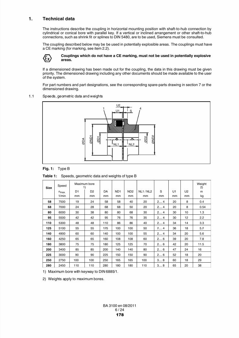
8/15/2019 r1_OF 71289_6 FF-AHF
http://slidepdf.com/reader/full/r1of-712896-ff-ahf 283/333
6 / 24BA 3100 en 08/2011
1. Technical data
The instructions describe the coupling in horizontal mounting position with shaft-to hub connection bycylindrical or conical bore with parallel key. If a vertical or inclined arrangement or other shaft-to-hubconnections, such as shrink fit or splines to DIN 5480, are to be used, Siemens must be consulted.
The coupling described below may be be used in potentially explosible areas. The couplings must havea CE marking (for marking, see item 2.2).
Couplings which do not have a CE marking, must not be used in potentially explosiveareas.
If a dimensioned drawing has been made out for the coupling, the data in this drawing must be givenpriority. The dimensioned drawing including any other documents should be made available to the userof the system.
For part numbers and part designations, see the corresponding spare-parts drawing in section 7 or thedimensioned drawing.
1.1 Speeds, geometric data and weights
U1 S
U2
NL1 NL2 ∅ D 1
∅ N D 1
∅ D A
∅ D 2
∅ N D 2
1 4
Fig. 1: Type BTable 1: Speeds, geometric data and weights of type B
SizeSpeed Maximum bore
1)Weight
2)nmax. D1 D2 DA ND1 ND2 NL1 / NL2 S U1 U2 m1/min mm mm mm mm mm mm mm mm mm kg
58 7500 19 24 58 58 40 20 2.... 4 20 8 0.4
68 7000 24 28 68 68 50 20 2.... 4 20 8 0.54
80 6000 30 38 80 80 68 30 2.... 4 30 10 1.3
95 5500 42 42 95 76 76 35 2.... 4 30 12 2.2
110 5300 48 48 110 86 86 40 2.... 4 34 14 3.3
125 5100 55 55 125 100 100 50 2.... 4 36 18 5.2
140 4900 60 60 140 100 100 55 2.... 4 34 20 5.6
160 4250 65 65 160 108 108 60 2.... 6 39 20 7.8
180 3800 75 75 180 125 125 70 2.... 6 42 20 11.5
200 3400 85 85 200 140 140 80 2.... 6 47 24 16
225 3000 90 90 225 150 150 90 2.... 6 52 18 20
250 2750 100 100 250 165 165 100 3.... 8 60 18 29
280 2450 110 110 280 180 180 110 3.... 8 65 20 38
1) Maximum bore with keyway to DIN 6885/1.
2) Weights apply to maximum bores.
178
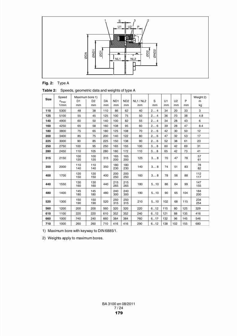
8/15/2019 r1_OF 71289_6 FF-AHF
http://slidepdf.com/reader/full/r1of-712896-ff-ahf 284/333
7 / 24BA 3100 en 08/2011
U2U1 P
NL1 NL2
S
∅
D 1
∅ N D 1
∅ D
A
∅
D 2
∅ N D 2
1 23
Fig. 2: Type A
Table 2: Speeds, geometric data and weights of type A
SizeSpeed Maximum bore 1) Weight 2)nmax D1 D2 DA ND1 ND2 NL1 / NL2 S U1 U2 P m1/min mm mm mm mm mm mm mm mm mm mm kg
110 5300 48 38 110 86 62 40 2.... 4 34 20 33 3125 5100 55 45 125 100 75 50 2.... 4 36 23 38 4.8
140 4900 60 50 140 100 82 55 2.... 4 34 28 43 6160 4250 65 58 160 108 95 60 2.... 6 39 28 47 8.4
180 3800 75 65 180 125 108 70 2.... 6 42 30 50 12200 3400 85 75 200 140 122 80 2.... 6 47 32 53 17225 3000 90 85 225 150 138 90 2.... 6 52 38 61 23
250 2750 100 95 250 165 155 100 3.... 8 60 42 69 31280 2450 110 105 280 180 172 110 3.... 8 65 42 73 41
315 2150 100120
100120 315 165
200165200 125 3.... 8 70 47 78 57
61
350 2000 110
140
110
140350 180
230
180
230140 3.... 8 74 51 83 78
82
400 1700 120150
120150 400 200
250200250 160 3.... 8 78 56 88 112
117
440 1550 130160
130160 440 215
265215265 180 5...10 86 64 99 147
155
480 1400 145180
145180 480 240
300240300 190 5...10 90 65 104 184
200
520 1300 150190
150190 520 250
315250315 210 5...10 102 68 115 234
254
560 1200 200 200 560 320 320 220 6...12 115 80 125 329610 1100 220 220 610 352 352 240 6...12 121 88 135 416660 1000 240 240 660 384 384 260 6...12 132 96 145 546
710 1000 260 260 710 416 416 290 6...12 138 102 155 6801) Maximum bore with keyway to DIN 6885/1.
2) Weights apply to maximum bores.
179

8/15/2019 r1_OF 71289_6 FF-AHF
http://slidepdf.com/reader/full/r1of-712896-ff-ahf 285/333
8 / 24BA 3100 en 08/2011
U2
U1
NL1 NL2 ∅ D 1
∅ N D 1
∅ D A ∅ D
2
∅ N D 2
S1 4
Fig. 3: Type BDS
Table 3: Speeds, geometric data and weights of type BDS
SizeSpeed Maximum bore
1)Weight
2)n
max.D1 D2 DA ND1 ND2 NL1 / NL2 S U1 U2 m
1/min mm mm mm mm mm mm mm mm mm kg
66 7500 19 24 66 66 40 20 2.... 4 20 8 0.5
76 7000 24 28 76 76 50 20 2.... 4 20 8 0.65
88 6000 30 38 88 88 68 30 2.... 4 30 10 1.8
103 5500 42 42 103 76 76 35 2.... 4 30 12 3
118 5300 48 48 118 86 86 40 2.... 4 34 14 3.7
135 5100 55 55 135 100 100 50 2.... 4 36 18 6.1
152 4900 60 60 152 108 100 55 2.... 4 36 20 7
172 4250 65 65 172 118 108 60 2.... 6 41 20 11
194 3800 75 75 194 135 125 70 2.... 6 44 20 17
218 3400 85 85 218 150 140 80 2.... 6 47 24 23245 3000 90 90 245 150 150 90 2.... 6 52 18 27
272 2750 100 100 272 165 165 100 3.... 8 60 18 36
305 2450 110 110 305 180 180 110 3.... 8 65 20 47
1) Maximum bore with keyway to DIN 6885/1.
2) Weights apply to maximum bores.
180

8/15/2019 r1_OF 71289_6 FF-AHF
http://slidepdf.com/reader/full/r1of-712896-ff-ahf 286/333
9 / 24BA 3100 en 08/2011
U2U1 P
NL1 NL2
S
∅ D 1
∅ N D 1
∅ D A
∅ D 2
∅ N D 2
1 3 2
Fig. 4: Type ADS
Table 4: Speeds, geometric data and weights of type ADS
SizeSpeed Maximum bore
1)Weight
2)n
max.D1 D2 DA ND1 ND2 NL1 / NL2 S U1 U2 P m
1/min mm mm mm mm mm mm mm mm mm mm kg
118 5300 48 38 118 86 62 40 2.... 4 34 20 33 3.5
135 5100 55 45 135 100 75 50 2.... 4 36 23 38 5.5
152 4900 60 50 152 108 82 55 2.... 4 36 28 43 7.7
172 4250 65 58 172 118 95 60 2.... 6 41 28 47 10.5
194 3800 75 65 194 135 108 70 2.... 6 44 30 50 15
218 3400 85 75 218 150 122 80 2.... 6 47 32 53 21
245 3000 90 85 245 150 138 90 2.... 6 52 38 61 28
272 2750 100 95 272 165 155 100 3.... 8 60 42 69 40
305 2450 110 105 305 180 172 110 3.... 8 65 42 73 50
340 2150 120 100120 340 200 165200 125 3.... 8 70 47 78 7273
380 2000 140 110140 380 230 180
230 140 3.... 8 74 51 83 100104
430 1700 150 120150 430 250 200
250 160 3.... 8 78 56 88 135140
472 1550 160 130160 472 265 215
265 180 5...10 86 64 99 174180
514 1400 180 145180 514 300 240
300 190 5...10 90 65 104 220237
556 1300 190 150190 556 315 250
315 210 5...10 102 68 115 281290
1) Maximum bore with keyway to DIN 6885/1.
2) Weights apply to maximum bores.
181

8/15/2019 r1_OF 71289_6 FF-AHF
http://slidepdf.com/reader/full/r1of-712896-ff-ahf 287/333
10 / 24BA 3100 en 08/2011
1.2 Flexible elements (12)
• Flexible elements may be stored for up to 5 years.
• Flexible elements must be protected against direct sunlight, artificial light with a high ultraviolet contentand extreme temperatures.
• Flexible elements must not come into contact with aggressive media.
• Flexible elements must not be heated up to impermissible temperatures during fitting work
(see table 5).• Flexible elements mus be replaced in sets; only identical flexible elements may be used in one
coupling.
Table 5: N-EUPEX flexible elementsMaterial Hardness Remark Mark Temperature range
NBR 80 Shore A Standard black flexible elementswith blue stripes 30 °C to + 80 °C
NBR 65 Shore ASpecial, soft,
shift of rotary resonance speed, nominaltorque reduced
black flexible elementswith green stripe 30 °C to + 80 °C
NBR 90 Shore ASpecial, hard,
shift of rotary resonance speedblack flexible elements
with magenta stripe 30 °C to + 80 °C
NBR 80 Shore A Special, increased (low backlash) black flexible elementswith yellow stripe 30 °C to + 80 °C
NBR 65 Shore ASpecial, increased (low backlash), shift
of rotary resonance speed, nominaltorque reduced
black flexible elementswith white stripe 30 °C to + 80 °C
NR 80 Shore A Special,use at low temperature
black flexible elementswith orange stripe 50 °C to + 50 °C
HNBR 80 Shore A Special,use at high temperature
black flexible elementswith red stripe 10 °C to + 100 °C
NBR 80 Shore A Special,electrically insulating green flexible elements 30 °C to + 80 °C
Electrically insulation flexible elements (green) are approved for explosion groups IIAand IIB.
High-temperature flexible elements (red marking) are not approved for use inpotentially explosive areas.
Table 6: N-EUPEX-DS flexible elementsMaterial Hardness Remark Mark Temperature range
NBR 80/90 Shore A Standard, 2 components,sizes 66 to 272 black flexible elements 30 °C to + 80 °C
NBR 90 Shore A Standard,Sizes 305 to 556 black flexible elements 30 °C to + 80 °C
PU 95 Shore A Special,Electrically insulating
blue / greenflexible elements 30 °C to + 50 °C
Electrically insulation flexible elements (blue / green) are approved for explosiongroups IIA and IIB.
182

8/15/2019 r1_OF 71289_6 FF-AHF
http://slidepdf.com/reader/full/r1of-712896-ff-ahf 288/333
11 / 24BA 3100 en 08/2011
2. Notes
2.1 Safety instructions and general notes
All persons involved in the installation, operation, maintenance and repair of thecoupling or clutch must have read and understood these instructions and mustcomply with them at all times. Disregarding these instructions may cause damage tothe product and material and/or injury to persons. Damage caused by disregard ofthese instructions will result in exclusion of liability.
During transport, installation, dismantling, operation and maintenance of the unit, the relevant safety andenvironmental regulations must be complied with at all times.
Lifting gears and load equipment for handling the components must be suitable for theweight of the coupling.
Depending on national regulations, coupling and clutch components may have to be disposed ofseparately or separated for recycling.
The coupling must be stored in a dry environment. Adequate preservation must be carried out.
Operators and users must not make any changes to the coupling themselves over and above the treatmentspecified in these instructions.
If there is any visible damage the coupling or clutch must not be fitted or put intooperation!
The coupling must not be operated unless housed in a suitable enclosure in accordance with the standardsapplying. This also applies to test runs and when checking the direction of rotation.
All work on the coupling must be carried out only when it is at a standstill. Secure the drive unit to preventunintentional switch-on. A notice should be attached to the ON switch stating clearly that work is inprogress.
In addition to any generally prescribed personal safety equipment (such as safety shoes, safety clothing,helmet) suitable safety gloves and suitable safety glasses must be worn when handling the couplingor clutch!
Only spare parts made by the manufacturer Siemens must be used.
Any enquiries should be addressed to:
Siemens AGSchlavenhorst 10046395 Bocholt
Tel.: +49 (0)2871 / 92 0Fax: +49 (0)2871 / 92 2596
183

8/15/2019 r1_OF 71289_6 FF-AHF
http://slidepdf.com/reader/full/r1of-712896-ff-ahf 289/333
12 / 24BA 3100 en 08/2011
2.2 Marking of the coupling parts for use in potentially explosive zones
Couplings which are ordered in Atex configuration, have the following marking on the outer circumferenceof coupling part 1:
Siemens AG II 2G T4 / T5 / T6 D120 °C
46393 Bocholt Germany ( 50 °C) 30 °C ≤ Ta ≤ + 80 °C / + 50 °C / + 40 °C
FLENDER couplings N EUPEX <year built> I M2
Coupling part 2 or coupling part 4 bear the marking .
The marking is in one or two lines.
If, in addition to the CE mark, the letter "U" together with the Siemens order number has been stampedon, the coupling part has been delivered by Siemens un- or prebored.
Siemens supplies unbored and prebored couplings with CE marking only under thecondition that the customer assumes the responsibility and liability for correctrefinishing in a declaration of exemption.
When using electrically insulating flexible elements, the marking of the explosiongroup IIA, IIB is added.
2.3 Service conditions
The coupling is suited for service conditions in accordance with Directive 94/9/EC:
• Equipment group II (use above ground) of categories 2 and 3 for areas where there are explosible gas,vapour, mist, air mixtures as well as for areas where dust can form explosible atmospheres.
• The permissible temperature classes and/or maximum surface temperatures are assigned asa function of the maximum ambient temperature occurring in the immediate vicinity of the coupling(see Table 7).
Table 7: Temperature classesAmbient temperature Temperature class max. surface temperature
max. 80 °C T4 < 108 °C
max. 50 °C T5 < 80 °C
max. 40 °C T6 < 68 °C
• Equipment group I (underground applications) of the category M2.
• Explosion group IIA or IIB in case of electrically insulating flexible elements.
If they are to be used below ground in potentially explosive areas the couplings mustonly be used with drive motors, which can be switched off on occurring of an
explosible atmosphere.The machines connected by the coupling must be earthed by an earth leakageresistance < 10 6 Ω.
If lacquered couplings are used in potentially explosive areas, the requirements madeof the conductivity of the lacquer and the limitation on the thickness of the lacquerapplied must be observed in accordance with EN 13463-1. Where lacquer coatingshave a thickness less than 200 µm, no electrostatic charge is to be expected.
184

8/15/2019 r1_OF 71289_6 FF-AHF
http://slidepdf.com/reader/full/r1of-712896-ff-ahf 290/333
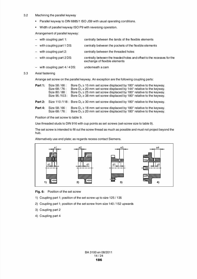
8/15/2019 r1_OF 71289_6 FF-AHF
http://slidepdf.com/reader/full/r1of-712896-ff-ahf 291/333
14 / 24BA 3100 en 08/2011
3.2 Machining the parallel keyway
• Parallel keyway to DIN 6885/1 ISO JS9 with usual operating conditions.
• Width of parallel keyway ISO P9 with reversing operation.
Arrangement of parallel keyway:
─ with coupling part 1: centrally between the lands of the flexible elements
─ with coupling part 1 DS: centrally between the pockets of the flexible elements ─ with coupling part 2: centrally between the threaded holes
─ with coupling part 2 DS: centrally between the treaded holes and offset to the recesses for theexchange of flexible elements
─ with coupling part 4 / 4 DS: underneath a cam
3.3 Axial fastening
Arrange set screw on the parallel keyway. An exception are the following coupling parts:
Part 1: Size 58 / 66 : Bore D1 ≥ 15 mm set screw displaced by 180° relative to the keyway.Size 68 / 76 : Bore D1 ≥ 20 mm set screw displaced by 144° relative to the keyway.
Size 80 / 88 : Bore D1 ≥ 25 mm set screw displaced by 180° relative to the keyway.Size 95 /103 : Bore D1 ≥ 38 mm set screw displaced by 180° relative to the keyway.
Part 2: Size 110 /118 : Bore D 1 ≥ 30 mm set screw displaced by 180° relative to the keyway.
Part 4: Size 58 / 66 : Bore D1 ≥ 18 mm set screw displaced by 180° relative to the keyway.Size 68 / 76 : Bore D1 ≥ 20 mm set screw displaced by 180° relative to the keyway.
Position of the set screw to table 9.
Use threaded studs to DIN 916 with cup points as set screws (set-screw size to table 9).
The set screw is intended to fill out the screw thread as much as possible and must not project beyond thehub.
Alternatively use end plate; as regards recess contact Siemens.
d1d1d1d1
e4e3e2e1
1) 2) 3) 4)
Fig. 6: Position of the set screw
1) Coupling part 1; position of the set screw up to size 125 / 135
2) Coupling part 1; position of the set screw from size 140 / 152 upwards
3) Coupling part 2
4) Coupling part 4
186

8/15/2019 r1_OF 71289_6 FF-AHF
http://slidepdf.com/reader/full/r1of-712896-ff-ahf 292/333
15 / 24BA 3100 en 08/2011
Table 9: Set-screw assignment, set-screw position and tightening torques
Size58 68 80 95 110 125 140 160 180 200 225 250 280 315 350 400 440 480 520 560 610 660 710
66 76 88 103 118 135 152 172 194 218 245 272 305 340 380 430 472 514 556
d1 M5 M6 M6 M6 M6 M8 M8 M10 M12 M12 M12 M16 M16 M16 M20 M20 M24 M24 M24 M24 M24 M24 M24
e1 10 10 11 15 18 20
e2 13 13 16 20 22 24 28 35 40 50 60 70 80 75 85 100 115
e3 9 12 15 20 30 30 35 40 45 50 60 70 80 90 100 100 110 130 140
e4 8 8 12 15 18 20 22 25 32 40 40 45 451) 3 4 4 4 4 8 8 15 25 25 25 70 70 70 130 130 230 230 230 230 230 230 230
1) Tightening torques of the set screws in Nm
Tightening torques apply to bolts with untreated surfaces which are not or only lightly oiled (coefficient offriction μ = 0.14). The use of lubricant paint or lubricant, which affects the coefficient of friction "µ", is notpermitted.
The specified tightening torques T A must be complied with, applying DIN 25202 Screw-ConnectionClass ”C”, with an output-torque scatter of ± 5 %.
3.4 Balancing after machining the finished bore
The balancing quality is to be specified in accordance with the specific application (however min. G16to DIN ISO 1940).
Balancing prescription to DIN ISO 8821 of the shaft must be observed.
Balancing bores must not affect the load-bearing capacity of the coupling parts .
The balancing bores must be applied on a large radius with sufficient distance to the lands / pockets of theflexible elements, cams and the outer circumference.
In case of coupling part 1 the bottom of the pockets of the flexible elements must notbe completely drilled through.
3.5 Installation of the coupling parts
Unscrew the set screw.
Clean holes and shaft ends.
Coat the bores of the coupling parts (1: 2; 4) and the shafts with MoS 2 mounting paste(e.g. Microgleit LP 405).
If demounted, position the coupling part 3 on the shaft before pulling coupling part 2 on.
Coupling parts (1; 2; 4) with tapered bore and parallel-key connection must be fittedin cold condition and secured with suitable end plates, without drawing the couplingparts (1; 2; 4) further onto the taper (fitting dimension = 0).
Place coupling parts (1; 2; 4), with cylindrical bore heat up to max. + 150 °C, if necessary. When heatingup observe the temperature range of the flexible elements (12) (see table 5 or 6), if necessary demountthe flexible elements (12).
Heated coupling parts form an explosion hazard, therefore a non-explosiveenvironment must be ensured.
187

8/15/2019 r1_OF 71289_6 FF-AHF
http://slidepdf.com/reader/full/r1of-712896-ff-ahf 293/333
16 / 24BA 3100 en 08/2011
Axial securing is effected by means of the set screw or end plate. When securing by set screw the shaftmust not project or be set back from the inner sides of the hub.
Fit the set screw or end plate (tightening torques of the set screw to table 9).
Failure to observe these instructions may result in breakage of the coupling.Danger from flying fragments!The coupling may then become an explosion hazard.
If necessary, re-fit flexible elements (12). Observe the temperature range (see table 5 or 6).Align the coupling as described in item 3.7.
3.6 Possible misalignments
∆Ka
1) 2) 3)
∆ K w
∆ K r
Smax.
Smin. Smin.
Smax.
Fig. 7: Possible misalignments
1) Axial misalignment (ΔKa)
2) Angular misalignment (ΔKw)
3) Radial misalignment (ΔKr)
3.6.1 Axial misalignment
The gap dimension ΔKa should be set within the deviation permitted for the dimension "S" (see section 1).
3.6.2 Angular misalignment
The angular misalignment ΔKw can be measured as difference of the gap dimension (ΔS = S max. – Smin.).ΔSperm., see table 10.
If required, the permissible angular misalignment ΔKw can be calculated as follows:
ΔKwperm. in RAD = ΔSperm. / DA ΔSperm. , see table 10.
ΔKwperm. in GRAD = (ΔSperm. / DA) x (180 / π) "DA" in mm see section 1.
3.6.3 Radial misalignment
The permissible radial misalignment ΔKrperm. can be found in table 10 (depending on the operating
speed).
188

8/15/2019 r1_OF 71289_6 FF-AHF
http://slidepdf.com/reader/full/r1of-712896-ff-ahf 294/333
17 / 24BA 3100 en 08/2011
3.7 Alignment
When aligning the angular and radial misalignment should be kept as low as possible.
Misalignment values specified in table 10 are maximum permissible overall values in operation, resultingfrom mispositioning through imprecision during alignment and misalignment through operation(e.g. deformation through load, heat expansion).
Reduced misalignment in the coupling minimises expected wear on the flexible elements. Misalignment
in the coupling gives rise to restorative forces which may impose inadmissible stress on adjacent machineparts (e.g. bearings).
3.8 Shaft-displacement values during operation
The following maximum permissible misalignments must by no means be exceeded duringoperation.When aligning the angular and radial misalignment should be kept appreciably smaller(tending towards zero).
Table 10: Shaft-displacement values ΔS perm. and ΔKperm., maximum permissible during operation,stated in mm (rounded)
Type, size Coupling speed in 1/minA, B ADS, BDS 250 500 750 1000 1500 2000 3000 4000 5000
58 66 0.4 0.3 0.25 0.2 0.2 0.15 0.15 0.1 0.1
68 76 0.4 0.3 0.25 0.2 0.2 0.15 0.15 0.1 0.180 88 0.4 0.3 0.25 0.2 0.2 0.15 0.15 0.1 0.1
95 103 0.5 0.35 0.25 0.25 0.2 0.2 0.15 0.1 0.1110 118 0.5 0.35 0.3 0.25 0.2 0.2 0.15 0.1 0.1
125 135 0.5 0.4 0.3 0.25 0.25 0.2 0.15 0.15 0.1140 152 0.6 0.4 0.35 0.3 0.25 0.2 0.2 0.15
160 172 0.6 0.5 0.4 0.35 0.3 0.25 0.2 0.15180 194 0.6 0.5 0.4 0.35 0.3 0.25 0.2
200 218 0.8 0.55 0.45 0.4 0.3 0.3 0.2225 245 0.8 0.55 0.5 0.4 0.35 0.3 0.25250 272 0.8 0.6 0.5 0.4 0.35 0.3280 305 1 0.7 0.6 0.5 0.4 0.35315 340 1 0.7 0.6 0.5 0.4 0.35350 380 1 0.8 0.6 0.6 0.5
400 430 1.2 0.9 0.7 0.6 0.5440 472 1.3 1 0.7 0.7 0.6
480 514 1.4 1 0.8 0.7520 556 1.5 1.1 0.9 0.8
560 1.6 1.2 1 0.8
610 1.8 1.3 1 0.9660 1.9 1.4 1.1 1
710 2 1.5 1.2
The numerical values of the table, as well as the intermediate values, can be calculated as follows:
ΔKrperm. = ΔSperm. = (0.1 + DA / 1000) x 40 / √n Coupling speed "n" in 1/min"DA" in mm, see section 1.Radial misalignment ΔKrperm. in mm
For speeds < 250 1/min the values in the colon "250 1/min" in table 10 apply.
189

8/15/2019 r1_OF 71289_6 FF-AHF
http://slidepdf.com/reader/full/r1of-712896-ff-ahf 295/333
18 / 24BA 3100 en 08/2011
3.9 Assignment of the tightening torques and wrench widths
The use of an impact screwdriver is not permissible!
Tightening torques apply to bolts with untreated surfaces which are not or only lightly oiled (coefficient offriction µ = 0.14). The use of lubricant paint or lubricant, which affects the coefficient of friction "µ", is notpermitted.
The specified tightening torques T A must be complied with, applying DIN 25202 Screw-Connection
Class ”C”, with an output-torque scatter of ± 5 %.The tightening torques and wrench widths of the set screws are specified in table 9.
Table 11: Tightening torques for part 13 of Types A and ADS
N EUPEX N EUPEX DS Tightening torque TA and wrench width SW forcoupling coupling hexagon socket screws to DIN EN ISO 4762
TA SWSize Size Nm mm
110 118 14 6125 135 17.5 6
140 152 29 8
160 172 35 8180 194 44 8200 218 67.5 10225 245 86 10250 272 145 14
280 305 185 14315 340 200 14
350 380 260 17400 430 340 17
440 472 410 17480 514 550 19
520 556 670 19560 710 19610 1450 22
660 1450 22710 1450 22
4. Start-up and operation
Bolt-tightening torques for the coupling and tightening torques for the foundationbolts of the coupled machine must be checked before start-up. Enclosures (couplingprotection, contact guard) must be fitted!
Overload conditions during start-up cannot be excluded. If the coupling breaksthrough overload, metal parts may fly off and cause personal injury and/or materialdamage.
If it is to be used below ground in potentially explosive areas, the coupling, which ismade of cast iron or steel, must be provided with a robust casing to preclude the riskof ignition from e.g. friction, impact or friction sparks.The depositing of heavy metal oxides (rust) on the coupling must be precluded by thecasing or other suitable precautions.
The coupling must run with little noise and without vibration. Irregular behaviour must be treated as a faultrequiring immediate remedy. In case of fault the drive must be stopped at once. The necessary measuresfor repair must be taken in accordance with the safety regulations applying.
190

8/15/2019 r1_OF 71289_6 FF-AHF
http://slidepdf.com/reader/full/r1of-712896-ff-ahf 296/333
19 / 24BA 3100 en 08/2011
5. Faults, causes and remedy
5.1 Possible cause of fault
Change in alignment:– Rectify the cause of the change in alignment (e.g. loose foundation bolts).– Align the coupling.– Check the axial fastening and, if necessary, adjust.– Wear check of the flexible elements (12) as described in section 6.
Flexible elements (12) worn:– Wear check of the flexible elements (12) as described in section 6, if necessary replace flexible
elements (12).
5.2 Incorrect use
Failure to observe these instructions may result in breakage of the coupling.Danger from flying fragments!Through incorrect use the coupling may become an explosion hazard.
5.2.1 Frequent faults when selecting the coupling and/or coupling size
• Important information for describing the drive and the environment are not communicated.
• System torque too high.
• System speed too high.
• Application factor not correctly selected.
• Chemically aggressive environment not taken into consideration.
• The ambient temperature is not permissible.
• Finished bore with inadmissible diameter and/or inadmissible assigned fits.
• Machining of parallel keyways of which the width across corners is greater than the width acrosscorners of the parallel keyways to DIN 6885/1 with a maximum permissible bore.
• The transmission capacity of the shaft-to hub connection is not appropriate to the operating conditions.• Maximum load or overload conditions are not being taken into consideration.
• Dynamic load conditions are not being taken into consideration.
• Shaft-to hub connection resulting in impermissible material stress on the coupling.
• Operating conditions are being changed without authorisation.
• Coupling and machine / drive train form a critical torsional, axial and bending vibration system.
• Fatigue torque load too high.
5.2.2 Frequent faults when fitting the coupling
• Components with transport or other damage are being fitted.
• When fitting coupling parts in a heated condition, already fitted N-EUPEX flexible elements (12) arebeing excessively heated.
• The shaft diameter is beyond the specified tolerance range.
• Coupling parts are being interchanged, i.e. their assignment to the specified shaft is incorrect.
191

8/15/2019 r1_OF 71289_6 FF-AHF
http://slidepdf.com/reader/full/r1of-712896-ff-ahf 297/333

8/15/2019 r1_OF 71289_6 FF-AHF
http://slidepdf.com/reader/full/r1of-712896-ff-ahf 298/333
21 / 24BA 3100 en 08/2011
Table 12: Wear mark for the torsional backlash, Types A and BSize 58 68 80 95 110 125 140 160 180 200 225 250 280 315 350 400 440 480 520 560 610 660 710
Wear mark∆S V(mm)
5.5 5.5 5.0 6.0 7.0 8.0 8.0 8.0 8.0 8.5 9.0 10.0 11.5 10.5 11.5 13.0 14.0 15.5 17.5 17.5 19.5 21.0 22.5
Table 13: Wear mark for the torsional backlash, Types ADS and BDSSize 66 76 88 103 118 135 152 172 194 218 245 272 305 340 380 430 472 514 556
Wear mark∆S V(mm)
6.0 7.0 5.0 7.0 9.0 10.5 11.5 9.0 8.0 7.0 6.5 7.0 8.0 6.5 7.0 10.0 12.0 14.0 16.0
If the above specified maintenance instructions are not adhered to, a correct operationwithin the meaning of the explosion prevention requirements and/or Directive 94/9/ECcan no longer be guaranteed on Types A and B (types with form fitting of the metalparts).Use in potentially explosive areas is then not permitted.
Failure to observe these instructions may result in breakage of the coupling.Danger from flying fragments!
6.2 Replacement of wearing parts
Replacement of the flexible elements (12) is possible without shifting the coupled machines only onTypes A and ADS.
After releasing the connection of coupling parts 2/3, coupling part 3 is shifted axially. The flexibleelements (12) will then be made freely accessible by rotating coupling part 2. To facilitate the release ofcoupling part 3, on sizes 225 to 430 forcing-off threads are provided in coupling part 1. From size 440onwards the forcing-off thread is located within coupling part 3.
1) 2)
Fig. 9: Releasing coupling part 3
1) Forcing-off thread in coupling part 1 2) Forcing-off thread in coupling part 3
The flexible elements (12) must be replaced in sets. Only identical flexible elements (12) may be used.
For re-assembly, the instructions in sections 3 and 4 must be observed.
6.3 Demounting the coupling parts in case of shaft-to hub connection with parallel key
Move the coupled machines apart.
Remove the axial fastening (set screw, end plate). Mount suitable detaching device. Using a burner, heatcoupling part (1; 2; 4) along its length and above the parallel keyway (max. + 80 °C). When heating upobserve the temperature range of the flexible elements (12) (see tables 5 and 6), if necessary demount theflexible elements (12).
Burner and heated coupling parts form an explosion hazard; therefore a non-explosiveenvironment must be ensured.
Pull the coupling part off. Examine the hub bore and the shaft for damage, and protect against rust.Damaged parts must be replaced.
For re-assembly, the instructions in sections 3 and 4 must be observed.
193

8/15/2019 r1_OF 71289_6 FF-AHF
http://slidepdf.com/reader/full/r1of-712896-ff-ahf 299/333
22 / 24BA 3100 en 08/2011
7. Stocking spare parts
7.1 Spare parts
For ordering spare parts state the following data, as far as possible:
• Siemens order number and position
• Drawing number
• Coupling type and coupling size
• Part numer (see spare-parts list)
• Bore, bore tolerance, keyway and balancing as well as particular characteristics such asflange-connection dimensions, intermediate-shaft length, brake-drum dimensions
• Any special details such as temperature, electrically insulating
13312
1)
1 2 412116
2)
Fig. 10: Spare-parts drawing
1) Types A and ADS
2) Types B and BDS
Table 14: Spare-parts list
Type A, ADS Type B, BDS
Part number Designation Part number Designation
1 Coupling part 1 1 Coupling part 1
2 Coupling part 2 4 Coupling part 4
3 Coupling part 3 12 Flexible element
12 Flexible element
13 Cheese head bolt
16 Parallel pinonly on Type A Size 560 to 710
194

8/15/2019 r1_OF 71289_6 FF-AHF
http://slidepdf.com/reader/full/r1of-712896-ff-ahf 300/333
23 / 24BA 3100 en 08/2011
8. Declarations
8.1 EC Declaration of conformity
EC Declaration of conformity
within the meaning of EC Directive 94/9/EC of 23.03.1994 and the legal requirements laid down for itsimplementation
The manufacturer, Siemens AG, 46395 Bocholt, Germany, declares that the equipment described in theseoperating instructions:
FLENDER N EUPEX® andFLENDER N EUPEX DS®
couplings
Types A, Band ADS, BDS
is in conformity with Article 1 and Article 8, Paragraph 1 b) ii) of Directive 94/9/EC and complies with therequirements of Directive 94/9/EC and the following standards:
DIN EN 1127‐1 : 02‐2008DIN EN 13463 1 : 07 2009
The technical documentation has been delivered to the body named below:DEKRA EXAM GmbH, D ‐ 44727 Bochum, code number: 0158.
Bocholt, 2011‐08‐22Andre Jansen(Director Engineering KUE)
Bocholt, 2011‐08‐22Nicola Warning(Director Business Subsegment KU)
195

8/15/2019 r1_OF 71289_6 FF-AHF
http://slidepdf.com/reader/full/r1of-712896-ff-ahf 301/333
Siemens AGIndustry SectorMechanical DrivesAlfred-Flender-Straße 7746395 BocholtGERMANY
www.siemens.com/drive-technologies
Subject to modifications
© Siemens AG 2011
Further Information:
"FLENDER gear units" on the Internetwww.siemens.com/gearunits
"FLENDER couplings" on the Internetwww.siemens.com/couplings
Service & Support:http://support.automation.siemens.com/WW/view/en/10803928/133300
Lubricants:http://support.automation.siemens.com/WW/view/en/42961591/133000
196

8/15/2019 r1_OF 71289_6 FF-AHF
http://slidepdf.com/reader/full/r1of-712896-ff-ahf 302/333197

8/15/2019 r1_OF 71289_6 FF-AHF
http://slidepdf.com/reader/full/r1of-712896-ff-ahf 303/333
FLENDER couplings
FLENDER ZAPEX®couplingsTypes ZIN, ZINA, ZINV,
ZIZS, ZIZA and ZIZV
Operating instructionsBA 3545 en 12/2011
198

8/15/2019 r1_OF 71289_6 FF-AHF
http://slidepdf.com/reader/full/r1of-712896-ff-ahf 304/333
2 / 32BA 3545 en 12/2011
FLENDER ZAPEX®couplings
Types ZIN, ZINA, ZINV,ZIZS, ZIZA and ZIZV
Operating instructionsTranslation of the original operating instructions
Technical data
Declarations
Stocking spare parts
Maintenanceand repair
Faults, causesand remedy
Start upand operation
Fitting
Notes
1
8
7
6
5
4
3
2
199
8/15/2019 r1_OF 71289_6 FF-AHF
http://slidepdf.com/reader/full/r1of-712896-ff-ahf 305/333
3 / 32BA 3545 en 12/2011
Notes and symbols in these operating instructions
Note: The term "operating instructions" will in the following also be shortened to "instructions" or "manual".
Legal notes
Warning note conceptThis manual comprises notes which must be observed for your personal safety and for preventing material damage.Notes for your personal safety are marked with a warning triangle or an "Ex" symbol (when applyingDirective 94/9/EC), those only for preventing material damage with a "STOP" sign.
WARNING! Imminent explosion!
The notes indicated by this symbol are given to prevent explosion damage.Disregarding these notes may result in serious injury or death.
WARNING! Imminent personal injury!
The notes indicated by this symbol are given to prevent personal injury.Disregarding these notes may result in serious injury or death.
WARNING! Imminent damage to the product!
The notes indicated by this symbol are given to prevent damage to the product.Disregarding these notes may result in material damage.
NOTE!
The notes indicated by this symbol must be treated as general operating information .Disregarding these notes may result in undesirable results or conditions.
WARNING! Hot surfaces!
The notes indicated by this symbol are made to prevent risk of burns due to hot surfacesand must always be observed.Disregarding these notes may result in light or serious injury.
Where there is more than one hazard, the warning note for whichever hazard is the most serious is always used.If in a warning note a warning triangle is used to warn of possible personal injury, a warning of material damage maybe added to the same warning note.
Qualified personnelThe product or system to which these instructions relate may be handled only by persons qualified for the workconcerned and in accordance with the instructions relating to the work concerned, particularly the safety and
warning notes contained in those instructions. Qualified personnel must be specially trained and have theexperience necessary to recognise risks associated with these products or systems and to avoid possible hazards.
200

8/15/2019 r1_OF 71289_6 FF-AHF
http://slidepdf.com/reader/full/r1of-712896-ff-ahf 306/333
4 / 32BA 3545 en 12/2011
Intended use of Siemens productsObserve also the following:
Siemens products must be used only for the applications provided for in the catalogue and the relevanttechnical documentation. If products and components of other makes are used, they must berecommended or approved by Siemens. The faultfree, safe operation of the products calls for propertransport, proper storage, erection, assembly, installation, start-up, operation and maintenance. Thepermissible ambient conditions must be adhered to. Notes in the relevant documentations must be
observed.
TrademarksAll designations indicated with the registered industrial property mark ® are registered trademarks of Siemens AG.Other designations used in these instructions may be trademarks the use of which by third parties for their ownpurposes may infringe holders’ rights.
Exclusion of liabilityWe have checked the content of the instructions for compliance with the hard- and software described.Nevertheless, variances may occur, and so we can offer no warranty for complete agreement. The informationgiven in these instructions is regularly checked, and any necessary corrections are included in subsequent editions.
Note on the EC Machinery Directive 2006/42/ECSiemens couplings in the "FLENDER couplings" product range must be treated as "components" in the senseof the EC Machinery Directive 2006/42/EC.Therefore, Siemens needs not issue a declaration of incorporation.Information on safe fitting, safe startup and safe operation can be found in this instruction manual; in addition the"warning note concept" therein must be observed.
201

8/15/2019 r1_OF 71289_6 FF-AHF
http://slidepdf.com/reader/full/r1of-712896-ff-ahf 307/333
5 / 32BA 3545 en 12/2011
Contents
1. Technical data 6. . . . . . . . . . . . . . . . . . . . . . . . . . . . . . . . . . . . . . . . . . . . . . . . . . . . .1.1 Types ZIN, ZINA 6. . . . . . . . . . . . . . . . . . . . . . . . . . . . . . . . . . . . . . . . . . . . . . . . . . . . . . . . . . . . . . . . . . . .1.2 Types ZIZS, ZIZA 7. . . . . . . . . . . . . . . . . . . . . . . . . . . . . . . . . . . . . . . . . . . . . . . . . . . . . . . . . . . . . . . . . . .1.3 Type ZINV 8. . . . . . . . . . . . . . . . . . . . . . . . . . . . . . . . . . . . . . . . . . . . . . . . . . . . . . . . . . . . . . . . . . . . . . . . .1.4 Type ZIZV 9. . . . . . . . . . . . . . . . . . . . . . . . . . . . . . . . . . . . . . . . . . . . . . . . . . . . . . . . . . . . . . . . . . . . . . . . .1.5 Dimension table 10. . . . . . . . . . . . . . . . . . . . . . . . . . . . . . . . . . . . . . . . . . . . . . . . . . . . . . . . . . . . . . . . . . . .1.5.1 O-rings (12) 10. . . . . . . . . . . . . . . . . . . . . . . . . . . . . . . . . . . . . . . . . . . . . . . . . . . . . . . . . . . . . . . . . . . . . . . .
2. Notes 11. . . . . . . . . . . . . . . . . . . . . . . . . . . . . . . . . . . . . . . . . . . . . . . . . . . . . . . . . . . . .2.1 Safety instructions and general notes 11. . . . . . . . . . . . . . . . . . . . . . . . . . . . . . . . . . . . . . . . . . . . . . . . . .2.2 Marking of the coupling parts for use in potentially explosive zones 12. . . . . . . . . . . . . . . . . . . . . . . . .2.3 Service conditions 12. . . . . . . . . . . . . . . . . . . . . . . . . . . . . . . . . . . . . . . . . . . . . . . . . . . . . . . . . . . . . . . . . .
3. Fitting 13. . . . . . . . . . . . . . . . . . . . . . . . . . . . . . . . . . . . . . . . . . . . . . . . . . . . . . . . . . . . .3.1 Machining the finished bore 13. . . . . . . . . . . . . . . . . . . . . . . . . . . . . . . . . . . . . . . . . . . . . . . . . . . . . . . . . .3.2 Machining the parallel keyway 13. . . . . . . . . . . . . . . . . . . . . . . . . . . . . . . . . . . . . . . . . . . . . . . . . . . . . . . .3.3 Axial fastening 14. . . . . . . . . . . . . . . . . . . . . . . . . . . . . . . . . . . . . . . . . . . . . . . . . . . . . . . . . . . . . . . . . . . . . .3.4 Balancing after machining the finished bore 15. . . . . . . . . . . . . . . . . . . . . . . . . . . . . . . . . . . . . . . . . . . . .3.5 Fitting the coupling parts (1/2) in case of shaft-hub connection with parallel key 15. . . . . . . . . . . . . .3.6 Fitting of coupling parts (1/2) in case of a cylindrical and tapered interference fit set up
for removal by oil-hydraulic shrinking-off 16. . . . . . . . . . . . . . . . . . . . . . . . . . . . . . . . . . . . . . . . . . . . . . . .3.7 Installation of the coupling 16. . . . . . . . . . . . . . . . . . . . . . . . . . . . . . . . . . . . . . . . . . . . . . . . . . . . . . . . . . . .3.8 Alignment 17. . . . . . . . . . . . . . . . . . . . . . . . . . . . . . . . . . . . . . . . . . . . . . . . . . . . . . . . . . . . . . . . . . . . . . . . . .3.9 Possible misalignments 18. . . . . . . . . . . . . . . . . . . . . . . . . . . . . . . . . . . . . . . . . . . . . . . . . . . . . . . . . . . . . .3.9.1 Axial misalignment 18. . . . . . . . . . . . . . . . . . . . . . . . . . . . . . . . . . . . . . . . . . . . . . . . . . . . . . . . . . . . . . . . . .3.9.2 Angular misalignment 18. . . . . . . . . . . . . . . . . . . . . . . . . . . . . . . . . . . . . . . . . . . . . . . . . . . . . . . . . . . . . . . .3.9.3 Radial misalignment 18. . . . . . . . . . . . . . . . . . . . . . . . . . . . . . . . . . . . . . . . . . . . . . . . . . . . . . . . . . . . . . . . .3.10 Distance between teeth VA and recommended alignment values for angular
and radial misalignment 19. . . . . . . . . . . . . . . . . . . . . . . . . . . . . . . . . . . . . . . . . . . . . . . . . . . . . . . . . . . . . .3.11 Distance dimensions "S" 20. . . . . . . . . . . . . . . . . . . . . . . . . . . . . . . . . . . . . . . . . . . . . . . . . . . . . . . . . . . . .
3.12 Assignment of the tightening torques and wrench widths 20. . . . . . . . . . . . . . . . . . . . . . . . . . . . . . . . . .4. Start-up and operation 21. . . . . . . . . . . . . . . . . . . . . . . . . . . . . . . . . . . . . . . . . . . . .4.1 Requirements for grease 21. . . . . . . . . . . . . . . . . . . . . . . . . . . . . . . . . . . . . . . . . . . . . . . . . . . . . . . . . . . . .4.2 Recommended lubricants 21. . . . . . . . . . . . . . . . . . . . . . . . . . . . . . . . . . . . . . . . . . . . . . . . . . . . . . . . . . . .4.3 Grease quantity 22. . . . . . . . . . . . . . . . . . . . . . . . . . . . . . . . . . . . . . . . . . . . . . . . . . . . . . . . . . . . . . . . . . . . .4.4 Procedure before start-up 22. . . . . . . . . . . . . . . . . . . . . . . . . . . . . . . . . . . . . . . . . . . . . . . . . . . . . . . . . . . .
5. Faults, causes and remedy 23. . . . . . . . . . . . . . . . . . . . . . . . . . . . . . . . . . . . . . . . .5.1 Possible cause of fault 23. . . . . . . . . . . . . . . . . . . . . . . . . . . . . . . . . . . . . . . . . . . . . . . . . . . . . . . . . . . . . . .5.2 Incorrect use 23. . . . . . . . . . . . . . . . . . . . . . . . . . . . . . . . . . . . . . . . . . . . . . . . . . . . . . . . . . . . . . . . . . . . . . .5.2.1 Frequent faults when selecting the coupling and/or coupling size 23. . . . . . . . . . . . . . . . . . . . . . . . . . .5.2.2 Frequent faults when fitting the coupling 24. . . . . . . . . . . . . . . . . . . . . . . . . . . . . . . . . . . . . . . . . . . . . . . .
5.2.3 Frequent faults in maintenance 24. . . . . . . . . . . . . . . . . . . . . . . . . . . . . . . . . . . . . . . . . . . . . . . . . . . . . . . .6. Maintenance and repair 24. . . . . . . . . . . . . . . . . . . . . . . . . . . . . . . . . . . . . . . . . . . .6.1 General 24. . . . . . . . . . . . . . . . . . . . . . . . . . . . . . . . . . . . . . . . . . . . . . . . . . . . . . . . . . . . . . . . . . . . . . . . . . . .6.2 Changing grease 25. . . . . . . . . . . . . . . . . . . . . . . . . . . . . . . . . . . . . . . . . . . . . . . . . . . . . . . . . . . . . . . . . . . .6.3 Replacing O-rings 25. . . . . . . . . . . . . . . . . . . . . . . . . . . . . . . . . . . . . . . . . . . . . . . . . . . . . . . . . . . . . . . . . . .6.4 Demounting the coupling 26. . . . . . . . . . . . . . . . . . . . . . . . . . . . . . . . . . . . . . . . . . . . . . . . . . . . . . . . . . . . .6.5 Demounting the coupling parts (1/2) in case of shaft-hub connection with parallel key 26. . . . . . . . .6.6 Demounting coupling parts (1/2) in case of cylindrical and tapered interference fit set up
for oil-hydraulic shrinking-off 26. . . . . . . . . . . . . . . . . . . . . . . . . . . . . . . . . . . . . . . . . . . . . . . . . . . . . . . . . .6.6.1 Demounting the coupling parts (1/2) in case of cylindrical interference fit 27. . . . . . . . . . . . . . . . . . . .6.6.2 Demounting the coupling parts (1/2) in case of tapered interference fit 28. . . . . . . . . . . . . . . . . . . . . .
7. Stocking spare parts 29. . . . . . . . . . . . . . . . . . . . . . . . . . . . . . . . . . . . . . . . . . . . . . .7.1 Spare parts 29. . . . . . . . . . . . . . . . . . . . . . . . . . . . . . . . . . . . . . . . . . . . . . . . . . . . . . . . . . . . . . . . . . . . . . . .
8. Declarations 31. . . . . . . . . . . . . . . . . . . . . . . . . . . . . . . . . . . . . . . . . . . . . . . . . . . . . . .8.1 EC declaration of conformity 31. . . . . . . . . . . . . . . . . . . . . . . . . . . . . . . . . . . . . . . . . . . . . . . . . . . . . . . . . .
202

8/15/2019 r1_OF 71289_6 FF-AHF
http://slidepdf.com/reader/full/r1of-712896-ff-ahf 308/333
6 / 32BA 3545 en 12/2011
1. Technical data
The instructions describe the coupling with shaft-hub connection by cylindrical bore with parallel key or inconfiguration for removal by oil-hydraulic shrinking-off.If different shaft-hub connections are to be used, such as drive-type parallel-key connection, splines toDIN 5480, Siemens should be consulted.
The coupling described below may be used in potentially explosible areas. The couplings must have a CEmarking (for marking, see item 2.2).
Couplings which do not have a CE marking must not be used in potentially explosiveareas.
If a dimensioned drawing has been made out for the coupling, the data on this drawing must be givenpriority. The dimensioned drawing including any other documents should be made available to the userof the system.
For part numbers and part designations, see the corresponding spare-parts drawing in section 7 or thedimensioned drawing.
1.1 Types ZIN, ZINA
The type ZINA is only available in configuration A (S16). The distance dimensions S1, S2, S3 and S16 will
be found in section 3, item 3.11.For dimension table, see item 1.5.
1 2
∅ D A
S1
1)
NL1 NL2
3)2)
S3S2
P P
∅ D 4
∅ N D 1
∅ Q
∅ D 1
∅ D 2
∅ Q
∅ N D 2
∅ D 4
1 2 1 2 1 2
Fig. 1: Type ZIN
1) Version A 2) Version AB 3) Version B
S16
A
A
Fig. 2: Type ZINA
203
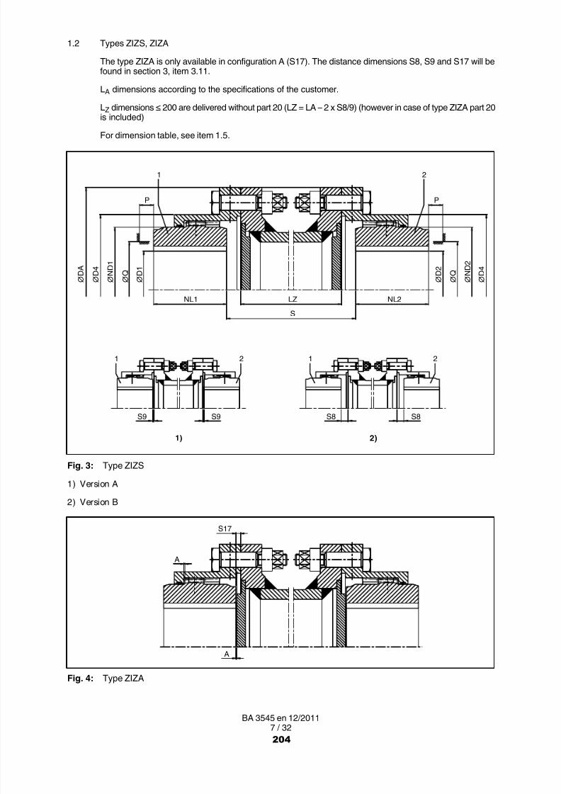
8/15/2019 r1_OF 71289_6 FF-AHF
http://slidepdf.com/reader/full/r1of-712896-ff-ahf 309/333
7 / 32BA 3545 en 12/2011
1.2 Types ZIZS, ZIZA
The type ZIZA is only available in configuration A (S17). The distance dimensions S8, S9 and S17 will befound in section 3, item 3.11.
LA dimensions according to the specifications of the customer.
LZ dimensions ≤ 200 are delivered without part 20 (LZ = LA – 2 x S8/9) (however in case of type ZIZA part 20is included)
For dimension table, see item 1.5.
1 2
∅ D A
S9
1)
NL1 NL2
2)
S8S9
P P
∅ D 4
∅ N D 1
∅ Q
∅ D 1
∅ D 2
∅ Q
∅ N D 2
∅ D 4
1 2 1 2
S8
LZ
S
Fig. 3: Type ZIZS
1) Version A
2) Version B
A
S17
A
Fig. 4: Type ZIZA
204

8/15/2019 r1_OF 71289_6 FF-AHF
http://slidepdf.com/reader/full/r1of-712896-ff-ahf 310/333
8 / 32BA 3545 en 12/2011
1.3 Type ZINV
The distance dimensions S11 and S12 will be found in section 3, item 3.11.
For dimension table, see item 1.5.
P
∅D4
P
N L 1
N L 2
∅Q
∅D1
∅ND1
∅D2
∅ND2
∅D4
∅Q
∅DA
S 1 1
S 1 2
1
2
1)
2)
Fig. 5: Type ZINV
1) top2) bottom
205
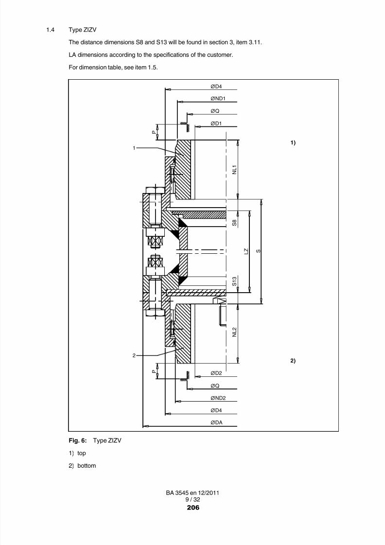
8/15/2019 r1_OF 71289_6 FF-AHF
http://slidepdf.com/reader/full/r1of-712896-ff-ahf 311/333
9 / 32BA 3545 en 12/2011
1.4 Type ZIZV
The distance dimensions S8 and S13 will be found in section 3, item 3.11.
LA dimensions according to the specifications of the customer.
For dimension table, see item 1.5.
P
∅D4
P
N L 1
N L 2
∅Q
∅D1
∅ND1
∅D2
∅ND2
∅D4
∅Q
∅DA
L Z S
11)
2)2
S 1 3
S 8
Fig. 6: Type ZIZV
1) top2) bottom
206

8/15/2019 r1_OF 71289_6 FF-AHF
http://slidepdf.com/reader/full/r1of-712896-ff-ahf 312/333
10 / 32BA 3545 en 12/2011
1.5 Dimension table
Table 1: Torques, speeds, geometric data and weights
Size
Ratedtorque Speed Hole
Axialback-lash
Weight
T N n max. D1 / D2 Da ND1ND2
NL1NL2 D4 A Q P LZ
1)from up to
2) 3) 3)min.
4)Nm 1/min mm mm mm mm mm mm mm mm mm mm kg
1 850 8500 0 50 117 67 43 83 0.5 52 31 75 3.2
1.5 1700 7700 0 64 152 87 50 107 0.5 68 34 85 6.5
2 3350 6900 0 80 178 108 62 129.5 0.5 85 42 95 9.8
2.5 6000 6200 0 98 213 130 76 156 0.5 110 47 110 17.5
3 10000 5800 0 112 240 153 90 181 0.5 130 58 110 25.5
3.5 16000 5100 0 133 280 180 105 211 0.5 150 67 125 43
4 23600 4500 0 158 318 214 120 249.5 1.0 175 72 125 60
4.5 33500 4000 80 172 347 233 135 274 1.0 190 81 125 82
5 47500 3750 90 192 390 260 150 307 1.0 220 91 145 115
5.5 67000 3550 100 210 425.5 283 175 332.5 1.0 250 104 145 155
6 90000 3400 120 232 457 312 190 364 1.0 265 126 145 180
7 125000 3200 150 276 527 371 220 423.5 1.0 300 140 145 275
The max. speed for types ZIZS, ZIZA and ZIZV is limited by the weight and the criticalspeed of the adapter.Speed n max. on request.
1) The specified torques relate to the teeth and not to the shaft-hub connection. This must be checkedseparately.
2) Max. bore with keyway to DIN 6885/1.
3) Space required for aligning the coupling parts, replacing the sealing rings and tightening the set screws.
4) Weights apply to maximum bores of type ZIN.
1.5.1 O-rings (12)
• O-rings may be stored for up to 5 years.
• O-rings must be protected against direct sunlight, artificial light with a ultraviolet content and extremetemperatures.
• O-rings must not come into contact with aggressive media.
• O-Rings must not be heated up to more than 80 °C during fitting work.
The O-rings (12) must not be stored while still fastened on the coupling part (1/2).
207

8/15/2019 r1_OF 71289_6 FF-AHF
http://slidepdf.com/reader/full/r1of-712896-ff-ahf 313/333
11 / 32BA 3545 en 12/2011
2. Notes
2.1 Safety instructions and general notes
All persons involved in the installation, operation, maintenance and repair of thecoupling or clutch must have read and understood these instructions and mustcomply with them at all times. Disregarding these instructions may cause damage tothe product and material and/or injury to persons. Damage caused by disregard ofthese instructions will result in exclusion of liability.
During transport, installation, dismantling, operation and maintenance of the unit, the relevant safety andenvironmental regulations must be complied with at all times.
Lifting gears and load equipment for handling the components must be suitable for theweight of the coupling.
Depending on national regulations, coupling and clutch components may have to be disposed ofseparately or separated for recycling.
The coupling must be stored in a dry environment. Adequate preservation must be carried out.
Operators and users must not make any changes to the coupling themselves over and above the treatmentspecified in these instructions.
If there is any visible damage the coupling or clutch must not be fitted or put intooperation!
The coupling must not be operated unless housed in a suitable enclosure in accordance with the standardsapplying. This also applies to test runs and when checking the direction of rotation.
All work on the coupling must be carried out only when it is at a standstill. Secure the drive unit to preventunintentional switch-on. A notice should be attached to the ON switch stating clearly that work is inprogress.
In addition to any generally prescribed personal safety equipment (such as safety shoes, safety clothing,helmet) suitable safety gloves and suitable safety glasses must be worn when handling the couplingor clutch!
Only spare parts made by the manufacturer Siemens must be used.
Any enquiries should be addressed to:
Siemens AGSchlavenhorst 10046395 Bocholt
Tel.: +49 (0)2871 / 92 0Fax: +49 (0)2871 / 92 2596
208
8/15/2019 r1_OF 71289_6 FF-AHF
http://slidepdf.com/reader/full/r1of-712896-ff-ahf 314/333
12 / 32BA 3545 en 12/2011
2.2 Marking of the coupling parts for use in potentially explosive zones
Couplings which are ordered in Atex configuration have the following marking on the flanged sleeve (5):
Siemens AG II 2GD c 120 °C (T4)
46395 Bocholt Germany I M2
FLENDER couplings ZAPEX <year built> 20 °C ≤ T a ≤ + 80 °C
The second flanged sleeve (5) and the coupling parts (1/2) bear the marking stamped on.
The marking is in one or two lines.
If, in addition to the CE mark, the letter "U" together with the Siemens order number has been stampedon, the coupling part has been delivered by Siemens un- or prebored.
Siemens supplies unbored and prebored couplings with CE marking only under thecondition that the customer assumes the responsibility and liability for correctrefinishing in a declaration of exemption.
2.3 Service conditions
The coupling is suited for service conditions in accordance with Directive 94/9/EC:
• Equipment group II (use above ground) of categories 2 and 3 for areas where there are explosible gas,vapour, mist, air mixtures as well as for areas where dust can form explosible atmospheres.
• Equipment group I (underground applications) of the category M2.
If they are to be used below ground in potentially explosive areas the couplings mustonly be used with drive motors, which can be switched off on occurring of anexplosible atmosphere.
The machines connected by the coupling must be earthed by an earth leakageresistance < 10 6 Ω.
If lacquered couplings are used in potentially explosive areas, the requirements madeof the conductivity of the lacquer and the limitation on the thickness of the lacquerapplied must be observed in accordance with DIN EN 13463-1. Where lacquer coatingshave a thickness less than 200 µm, no electrostatic charge is to be expected.
209

8/15/2019 r1_OF 71289_6 FF-AHF
http://slidepdf.com/reader/full/r1of-712896-ff-ahf 315/333
13 / 32BA 3545 en 12/2011
3. Fitting
Coupling parts (1/2) for removal by oil-hydraulic shrinking off are delivered in a finish-machined stateaccording to the order placed,
3.1 Machining the finished bore
Depreserve and clean coupling parts (1/2).
Clamp as shown in figure 7 and align.
Never clamp on the sealing surface of the O-ring.
Machine the finished bore, observe maximum bore described in section 1.
Check finished bore as described in section 7.
1) 2)
∅ D IT 6 3.2
IT 6 A
A
Fig. 7: Machining the finished bore
1) Sealing surface
2) Chuck
Table 2: Fit recommendation
Description Interference fit with parallel key connection, suitable for reversing operation
Shaft tolerance h6 k6 m6 n6 p6 s6
Bore tolerance P7 M7 K7 J7 H7 F7
Failure to observe these instructions may result in breakage of the coupling.Danger from flying fragments!The coupling may then become an explosion hazard.
3.2 Machining the parallel keyway
• Parallel keyway to DIN 6885/1 ISO P9 with one keyway .
• Parallel keyway to DIN 6885/1 ISO JS9 with two keyways .
210

8/15/2019 r1_OF 71289_6 FF-AHF
http://slidepdf.com/reader/full/r1of-712896-ff-ahf 316/333
14 / 32BA 3545 en 12/2011
3.3 Axial fastening
Arrange set screw on the parallel keyway.
Position of the set screw to table 3, thereby considering the configuration A or B for the coupling parts (1/2).
Use threaded studs to DIN 916 with cup points as set screws (set-screw size to table 3).
The set screw is intended to fill out the screw thread as much as possible and must not project beyond thehub.
Alternatively use end plate; as regards recess contact Siemens.
2) 3)
1)e1 e2
d1 d1 ∅ D
∅ D
Fig. 8: Position of the set screw
1) Sealing surface
2) Version B
3) Version A
Table 3: Set-screw assignment, set-screw position and tightening torques
Size
Bore D d1 Tighteningtorque
Wrenchwidth e1 e2
TAHexagon
socket wrenchmm mm Nm mm mm mm
1 10 ... 17> 17 ... 50
M 5M 6
34
2.53 7 15
1.5 10 ... 17> 17 ... 64
M 5M 6
34
2.53 8 16
210 ... 17
> 17 ... 38> 38 ... 80
M 5M 6M 8
348
2.534
10 24
2.510 ... 17
> 17 ... 22> 22 ... 98
M 5M 6M 8
348
2.534
14 27
3
10 ... 17> 17 ... 22> 22 ... 30> 30 ... 65> 65 ... 112
M 5M 6M 8M10M12
348
1525
2.53456
16 30
3.5
10 ... 17> 17 ... 22> 22 ... 30> 30 ... 38> 38 ... 133
M 5M 6M 8M10M12
348
1525
2.53456
18 35
4
10 ... 17> 17 ... 22> 22 ... 30> 30 ... 38> 38 ... 50> 50 ... 158
M 5M 6M 8M10M12M16
348
152570
2.534568
22 40
4.5 80 ... 172 M16 70 8 25 45
5 90 ... 192 M16 70 8 30 45
211

8/15/2019 r1_OF 71289_6 FF-AHF
http://slidepdf.com/reader/full/r1of-712896-ff-ahf 317/333
15 / 32BA 3545 en 12/2011
Size
e2e1Wrenchwidth
Tighteningtorqued1Bore D
Size Hexagonsocket wrenchTA
Size
mmmmmmNmmmmm
5.5 100 ... 210 M16 70 8 30 50
6 120 ... 232 M20 130 10 30 50
7 150 ... 276 M24 230 12 30 50
Tightening torques apply to bolts with untreated surfaces which are not or only lightly oiled (coefficient offriction μ = 0.14). The use of lubricant paint or lubricant, which affects the coefficient of friction "µ", is notpermitted.
The specified tightening torques T A must be complied with, applying DIN 25202 Screw-ConnectionClass "C", with an output-torque scatter of ± 5 %.
3.4 Balancing after machining the finished bore
The balancing quality is to be specified in accordance with the specific application (however min. G16to DIN ISO 1940).
Balancing prescription to DIN ISO 8821 of the shaft must be observed.
Balancing bores must not affect the load-bearing capacity of the coupling parts.
The balancing bores must be applied on a large radius with sufficient distance to the hub’s circumference.
Under no circumstances may the tooth system be damaged.
3.5 Fitting the coupling parts (1/2) in case of shaft-hub connection with parallel key
Unscrew the set screw.
Clean the holes and shaft ends.
Grease the cleaned flanged-sleeve grooves and then insert the O-rings (12).
Grease the teeth of the flanged sleeves (5) and place the flanged sleeves (5) on the shaft before pullingon the coupling parts (1/2).
Coat the bores of the coupling parts (1/2) and the shafts with MoS 2 mounting paste (e.g. Microgleit LP 405).
Coupling parts (1/2) with tapered bore and parallel-key connection must be fitted incold condition.
Place coupling parts (1/2), with cylindrical bore heat up to max. + 80 °C, if necessary.
Heated coupling parts form an explosion hazard, therefore a non-explosiveenvironment must be ensured.
Shafts must not project from the inner sides of the hub.
The coupling parts (1/2) with a tapered bore must be secured with suitable end plates. For this,smear the hub end face on the shaft end face with sealing compound and screw on the endplate.
On coupling parts (1/2) with keyway and set screw the threaded hole for the set screw must be filled 2/3with sealing compound after cooling down to room temperature to prevent lubricant from escaping throughthe parallel keyway. Screw in the set screw (set screw must be above the parallel key).
Tighten the set screw (for tightening torques, see table 3).
Failure to observe these instructions may result in breakage of the coupling.Danger from flying fragments!The coupling then becomes an explosion hazard.
212

8/15/2019 r1_OF 71289_6 FF-AHF
http://slidepdf.com/reader/full/r1of-712896-ff-ahf 318/333
16 / 32BA 3545 en 12/2011
3.6 Fitting of coupling parts (1/2) in case of a cylindrical and tapered interference fit set up for removal byoil-hydraulic shrinking-off
The information specified on the dimensioned drawing should be observed withpriority.
Unscrew screw plugs (22) from the coupling parts (1/2). Clean and dry holes and shaft ends. The oilchannels and oil-circulation grooves must also be free from dirt.
The machine shaft and the bore of the coupling part must be absolutely clean and freefrom grease and oil!
Grease the cleaned flanged-sleeve grooves and then insert the O-rings (12).
Grease the teeth of the flanged sleeves (5) and place the flanged sleeves (5) on the shaft before pullingon the coupling parts (1/2).
Protect O-rings (12) and seals for the input and output side against damage andheating to above + 80 °C.(Use heat shields to protect against radiant heat.)
The coupling parts (1/2) must be fitted in hot condition and, depending on the shrink dimension, heatedto the temperature indicated on the dimensioned drawing.
Heating may be done inductively, in a stove or with a burner.
Burner and heated coupling parts form an explosion hazard; therefore a non-explosiveenvironment must be ensured.
Before mounting, the bore size of the heated coupling parts (1/2) must be checked, e.g. with a bore holegauge.
The couplings parts (1/2) should be pushed smartly onto the shaft up to the position specified on thedimensioned drawing.
The coupling parts (1/2) must be held in position on the shaft with the aid of a suitableretaining device, until they cool down and seat firmly.
After the coupling parts (1/2) have cooled down to ambient temperature the oil channels must be filled withclean forcing oil, e.g. ISO VG 150, and re-sealed with the screw plugs (22) (rust protection).
Failure to observe these instructions may result in breakage of the coupling.Danger from flying fragments!The coupling then becomes an explosion hazard.
3.7 Installation of the coupling
Grease the teeth on the coupling parts (1/2) and the flanged sleeves (5) and the hub circumference of thecoupling parts (1/2) (sealing surfaces).
Screw the thrust piece (34) into the lower machine shaft in case of types ZINV and ZIZV.
Using suitable tools, pull the flanged sleeves (5) onto the hub and over the teeth of the coupling parts (1/2)and hold or brace them in position.
In case of type ZINA put the axial backlash limiting device (51) into the flanged sleeve (5).
In case of types ZINV and ZIZV the spacer washer (33) should be placed on the pressure piece (34) andinto the flanged sleeve (5).
Move together and align the machines to be coupled (see item 3.8).
Smear the sealing surfaces of the flanged sleeves (5) and the adapter (4), if any, with sealing compound.Align the fitting holes of the flanges, noting any marks. Insert close-fitting bolts (8) and tighten the nuts (9)(for tightening torques, see item 3.12).
213

8/15/2019 r1_OF 71289_6 FF-AHF
http://slidepdf.com/reader/full/r1of-712896-ff-ahf 319/333
17 / 32BA 3545 en 12/2011
3.8 Alignment
To obtain the longest possible service life for the coupling, we recommend alignment with 20 % of theoffsets possible in operation specified in item 3.9. The recommended alignment values in numerical valuesare specified in item 3.10. Very precise alignment must not be aimed at, as this will impair the formationof the lubricant film in the coupling teeth.
Alignment must be carried out using suitable measuring instruments. The following diagram showsalignment suggestions and points of alignment ( A ).
Siemens recommendation:To prevent measuring errors caused by sagging of the clock gauge, it is recommended that thecoupling be aligned using laser technology.
1)
2)
3)
3)3)
2)
1)
S + ΔKa
Fig. 9: Alignment
1) Dial gauge
2) Measurement of distance
3) Ruler
214
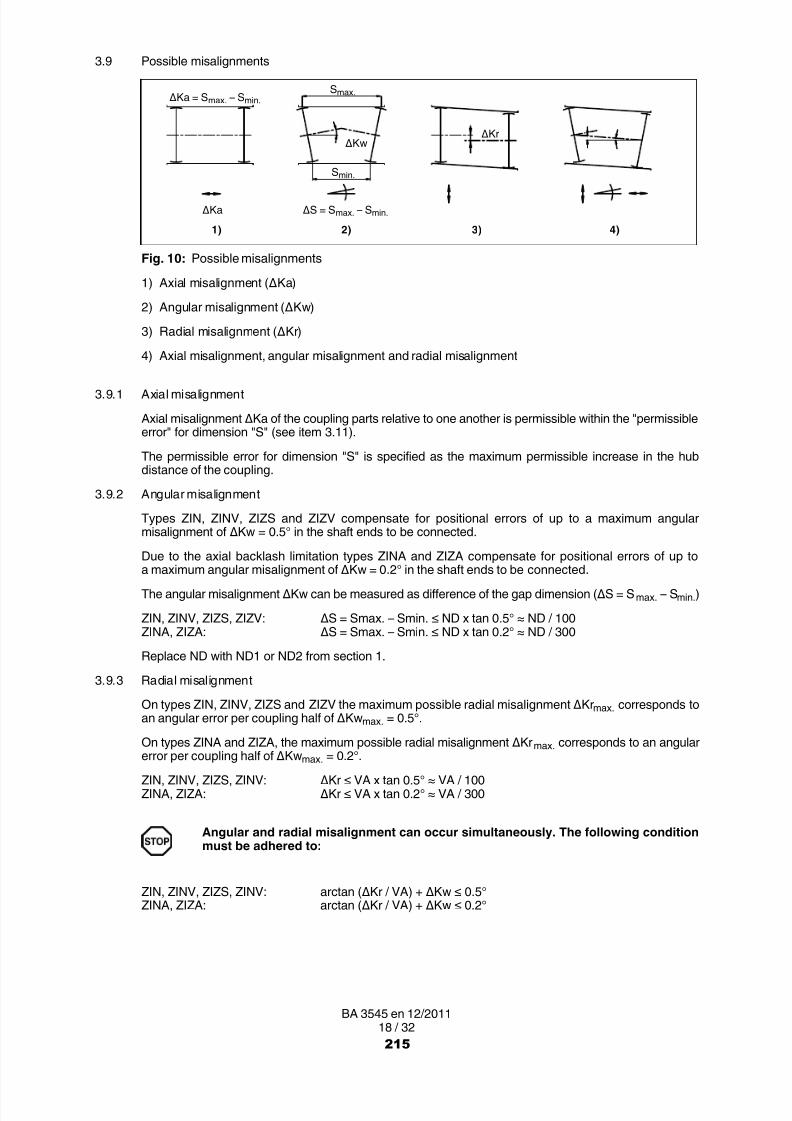
8/15/2019 r1_OF 71289_6 FF-AHF
http://slidepdf.com/reader/full/r1of-712896-ff-ahf 320/333
18 / 32BA 3545 en 12/2011
3.9 Possible misalignments
1) 3)2)
ΔKwΔKr
4)
ΔS = S max. – S min.
S max.
S min.
ΔKa
ΔKa = S max. – S min.
Fig. 10: Possible misalignments
1) Axial misalignment (ΔKa)
2) Angular misalignment (ΔKw)
3) Radial misalignment (ΔKr)
4) Axial misalignment, angular misalignment and radial misalignment
3.9.1 Axial misalignment
Axial misalignment ΔKa of the coupling parts relative to one another is permissible within the "permissibleerror" for dimension "S" (see item 3.11).
The permissible error for dimension "S" is specified as the maximum permissible increase in the hubdistance of the coupling.
3.9.2 Angular misalignment
Types ZIN, ZINV, ZIZS and ZIZV compensate for positional errors of up to a maximum angularmisalignment of ΔKw = 0.5° in the shaft ends to be connected.
Due to the axial backlash limitation types ZINA and ZIZA compensate for positional errors of up toa maximum angular misalignment of ΔKw = 0.2° in the shaft ends to be connected.
The angular misalignment ΔKw can be measured as difference of the gap dimension (ΔS = S max. – Smin. )
ZIN, ZINV, ZIZS, ZIZV: ΔS = Smax. – Smin. ≤ ND x tan 0.5° ≈ ND / 100ZINA, ZIZA: ΔS = Smax. – Smin. ≤ ND x tan 0.2° ≈ ND / 300
Replace ND with ND1 or ND2 from section 1.
3.9.3 Radial misalignment
On types ZIN, ZINV, ZIZS and ZIZV the maximum possible radial misalignment ΔKr max. corresponds toan angular error per coupling half of ΔKw max. = 0.5°.
On types ZINA and ZIZA, the maximum possible radial misalignment ΔKrmax.
corresponds to an angularerror per coupling half of ΔKw max. = 0.2°.
ZIN, ZINV, ZIZS, ZINV: ΔKr ≤ VA x tan 0.5° ≈ VA / 100ZINA, ZIZA: ΔKr ≤ VA x tan 0.2° ≈ VA / 300
Angular and radial misalignment can occur simultaneously. The following conditionmust be adhered to:
ZIN, ZINV, ZIZS, ZINV: arctan (ΔKr / VA) + ΔKw ≤ 0.5°ZINA, ZIZA: arctan (ΔKr / VA) + ΔKw ≤ 0.2°
215

8/15/2019 r1_OF 71289_6 FF-AHF
http://slidepdf.com/reader/full/r1of-712896-ff-ahf 321/333
19 / 32BA 3545 en 12/2011
3.10 Distance between teeth VA and recommended alignment values for angular and radial misalignment
ZIZS, ZIZV
VA5
ZIN, ZINV
VA1
ZIZA
VA6
ZINA
VA2
Fig. 11: Possible misalignments
Table 4: Distance between teeth, recommended alignment values for angular and radial misalignment
Size
Distance between teeth Radial misalignment ΔKrat
Angularmisalignment ΔS
VA1 VA5 VA2 VA6 VA1 VA2 VA5; VA6mm mm mm mm mm mm mm mm
1 55
VA1 + LZ
57
VA2 + LZ
0.09 0.1
Δ K r =
V A 5 x t a n 0
. 1 °
Δ K r =
V A 6 x t a n 0
. 1 °
0.11
1.5 59 62 0.1 0.1 0.15
2 79 82 0.13 0.14 0.182.5 93 97 0.16 0.17 0.22
3 109 113 0.19 0.19 0.26
3.5 128 133 0.22 0.23 0.31
4 144 148 0.25 0.25 0.37
4.5 164 169 0.28 0.29 0.40
5 182 188 0.31 0.32 0.45
5.5 214 220 0.37 0.38 0.49
6 236 242 0.41 0.42 0.54
7 263 271 0.45 0.47 0.64
Due to the limited axial backlash, in case of types ZINA and ZIZA the alignment values
must be cut by half.
216

8/15/2019 r1_OF 71289_6 FF-AHF
http://slidepdf.com/reader/full/r1of-712896-ff-ahf 322/333
20 / 32BA 3545 en 12/2011
3.11 Distance dimensions "S"
Table 5: Distance dimensions "S" for types ZIN (S1, S2, S3), ZINA (S16), ZIZA (S17), ZIZS (S8, S9),ZINV (S11, S12) und ZIZV (S8, S13)
perm.misalign
ment
perm.misalign‐
mentSize S1 S2 S3 S1, S2, S3 S8 S9 S11 S12 S8, S9,
S11, S12S13 S16 S17
mm mm mm mm mm mm mm mm mm mm mm mm
1 3 12 21 + 1 10.5 1.5 8 21 + 0.5 10.5 5 2.5
1.5 3 9 15 + 1 7.5 1.5 4.5 15 + 0.5 7.5 6 3
2 3 17 31 + 1 15.5 1.5 12.5 31 + 0.5 15.5 6 3
2.5 5 17 29 + 1 14.5 2.5 10.5 29 + 0.5 14.5 9 4.5
3 5 19 33 + 1 16.5 2.5 12.5 33 + 0.5 16.5 9 4.5
3.5 6 23 40 + 1 20 3 15 40 + 0.5 20 11 5.5
4 6 24 42 + 1 21 3 17 42 + 0.5 21 10 5
4.5 8 29 50 + 1.5 25 4 19.5 50 + 0.75 25 13 6.5
5 8 32 56 + 1.5 28 4 22 56 + 0.75 28 14 7
5.5 8 39 70 + 1.5 35 4 29 70 + 0.75 35 14 7
6 8 46 84 + 1.5 42 4 36 84 + 0.75 42 14 7
7 10 43 76 + 1.5 38 5 30 76 + 0.75 38 18 9
For S16, S17 errors of ± 0.1 mm are permissible.
3.12 Assignment of the tightening torques and wrench widths
The use of an impact screwdriver is not permissible!
Tightening torques apply to bolts with untreated surfaces which are not or only lightly oiled (coefficient offriction µ = 0.14). The use of lubricant paint or lubricant, which affects the coefficient of friction "µ", is not
permitted.The specified tightening torques T A must be complied with, applying DIN 25202 Screw-ConnectionClass "C", with an output-torque scatter of ± 5 %.
The tightening torques and wrench widths of the set screws are specified in table 3.
Table 6: Tightening torques and wrench widths of the parts 6 and 9
Size
Tightening torques T A Wrench width SWfor bolts of the strength class 10.9 to DIN ISO 898 Part 1
(with µ = 0.14)Hexagon
socket wrenchHexagon
headPart no. 9 Part no. 6 Part no. 9
Nm mm mm
1 15 3 8
1.5 36 5 102 72 5 13
2.5 125 5 163 125 5 163.5 200 5 19
4 200 5 194.5 200 5 195 430 5 24
5.5 430 5 246 430 5 247 610 5 27
217

8/15/2019 r1_OF 71289_6 FF-AHF
http://slidepdf.com/reader/full/r1of-712896-ff-ahf 323/333
21 / 32BA 3545 en 12/2011
4. Start-up and operation
4.1 Requirements for grease
For ZAPEX-ZI couplings, only greases containing active agents for increasing corrosion protection andresistance to ageing and for reducing wear in mixed-friction areas are approved.
• Greases must have been manufactured on the base of mineral oil.
• Viscosity class for greases: DIN 51818, NLGI 0, NLGI 00.• Suitablity for sealing rings made of elastomer materials NBR and FPM.
• Compatibility with liquid seals: LOCTITE 5910, 5922
Lubricants must never be mixed with other substances.Before mixing different types of lubricants always ask the manufacturer on thecompatibility of the lubricants.
4.2 Recommended lubricants
The following lubricant recommendations apply to the ZAPEX couplings described in these instructions.
Table 7: Lubricants
Lubricantperformance
Liquefied greases FDP 00 EnergreaseLS‐EP 00
Tribol 3020/1000‐00◆ Longtime PD 00
FLENDERHochleistungsfett
Lubricant
Liquefied greases RENOLITSO‐D 6024
GRAFLOSCONC‐SG 500 Plus Mobilux EP 004 Alvania GL 00
The lubricants are suitable for operating temperatures of between - 20 °C and + 80 °C.◆ Lubricants with this mark are suitable for operating temperatures of between - 40 °C and + 80 °C.
Observe manufacturer's instructions for handling lubricants!
218

8/15/2019 r1_OF 71289_6 FF-AHF
http://slidepdf.com/reader/full/r1of-712896-ff-ahf 324/333
22 / 32BA 3545 en 12/2011
4.3 Grease quantity
If the grease filling quantity is not in accordance with the specified quantity, thecoupling may become an explosion hazard.
Table 8: Grease quantities
Size
Grease quantity 1)
Size
Grease quantity 1)
Size
Grease quantity 1)
ZIN, ZINA ZIZS, ZIZA ZIN, ZINA ZIZS, ZIZA ZIN, ZINA ZIZS, ZIZA
dm 3 dm 3 dm 3 dm 3 dm 3 dm 3
1 0.04 0.02 3 0.33 0.17 5 1.4 0.7
1.5 0.08 0.04 3.5 0.42 0.21 5.5 1.8 0.9
2 0.16 0.08 4 0.7 0.35 6 2.3 1,15
2.5 0.2 0.1 4.5 0.9 0.45 7 3.0 1.5
1) In case of types ZIZS and ZISA the grease filling quantities are valid for one coupling side.
For the grease quantities for types ZINV and ZIZV, refer to the dimensioned drawings.
For easier filling, proceed as follows:Rotate coupling until the screw plugs (6) are in the position shown in the diagram opposite.
The two screw plugs (6) must be removed and grease put in (if necessary, use a grease gun).
Screw in the screw plugs (6) with fitted/integrated sealing rings.
1) Filling hole
2) Ventilation hole
Fig. 12: Filling with grease
Any grease spillage must be completely collected and disposed of in accordance withthe regulations applying.
4.4 Procedure before start-up
Bolt-tightening torques for the coupling and tightening torques for the foundationbolts of the coupled machine must be checked before start-up. Enclosures (couplingprotection, contact guard) must be fitted!Overload conditions during start-up cannot be excluded. If the coupling breaksthrough overload, metal parts may fly off and cause personal injury and/or materialdamage.
If it is to be used below ground in potentially explosive areas, the coupling, which ismade of steel, must be provided with a robust casing to preclude the risk of ignitionfrom e.g. friction, impact or friction sparks.The depositing of heavy metal oxides (rust) on the coupling must be precluded by thecasing or other suitable precautions.
The coupling must run with little noise and without vibration. Irregular behaviour must be treated as a faultrequiring immediate remedy. In case of fault the drive must be stopped at once. The necessary measuresfor repair must be taken in accordance with the safety regulations applying.
2)1)
219

8/15/2019 r1_OF 71289_6 FF-AHF
http://slidepdf.com/reader/full/r1of-712896-ff-ahf 325/333
23 / 32BA 3545 en 12/2011
5. Faults, causes and remedy
5.1 Possible cause of fault
Change in alignment: ─ Rectify the cause of the change in alignment (e.g. loose foundation bolts). ─ Align the coupling. ─ Check the axial fastening and, if necessary, adjust.
Insufficient lubricant: ─ Take a small grease sample at the screw plug (6) and check, whether the grease can still be used. If
the consistence of the grease has changed, the grease should be changed as described in item 6.2. ─ In case of leakage the lost grease quantity must be recharged, or the grease should be changed as
described in item 6.2. In case of a complet grease change as described in item 6.2, the sealingrings (12) should also be replaced, as described in item 6.3.
5.2 Incorrect use
Failure to observe these instructions may result in breakage of the coupling.Danger from flying fragments!Through incorrect use the coupling may become an explosion hazard.
5.2.1 Frequent faults when selecting the coupling and/or coupling size
• Important information for describing the drive and the environment are not communicated.
• System torque too high.
• System speed too high.
• Application factor not correctly selected.
• Chemically aggressive environment not taken into consideration.
• The ambient temperature is not permissible.
• Finished bore with inadmissible diameter and/or inadmissible assigned fits.
• Machining of parallel keyways of which the width across corners is greater than the width acrosscorners of the parallel keyways to DIN 6885/1 with a maximum permissible bore.
• The transmission capacity of the shaft-hub connection is not appropriate to the operating conditions.
• Maximum load or overload conditions are not being taken into consideration.
• Dynamic load conditions are not being taken into consideration.
• Shaft-hub connection resulting in impermissible material stress on the coupling.
• Operating conditions are being changed without authorisation.
• Coupling and machine / drive train form a critical torsional, axial and bending vibration system.
• Fatigue torque load too high.
220

8/15/2019 r1_OF 71289_6 FF-AHF
http://slidepdf.com/reader/full/r1of-712896-ff-ahf 326/333
24 / 32BA 3545 en 12/2011
5.2.2 Frequent faults when fitting the coupling
• Components with transport or other damage are being fitted.
• When fitting coupling parts in a heated condition, sealing rings are being excessively heated.
• The shaft diameter is beyond the specified tolerance range.
• Coupling parts are being interchanged, i.e. their assignment to the specified shaft is incorrect.
• Specified axial fastenings are not fitted.• Specified tightening torques are not being adhered to.
• Bolts are inserted dry or greased.
• Flange surfaces of screwed connections have not been cleaned.
• Alignment and/or shaft-misalignment values do not match the specifications in the instructions manual.
• The coupled machines are not correctly fastened to the foundation, and as a result shifting of themachines e.g. due to loosening of the foundation-screw connection is causing excessive displacementof the coupling parts.
• The coupled machines are not sufficiently earthed.
• Sealing rings are not fitted.
• Sealing surfaces are being painted.
• The lubricant has not been correctly put in (see section 4).
• The back clearance of the parallel key has not been filled with sealing compound (when inserting theset screw no sealing compound has been put into the threaded hole).
• The coupling guard used is not suitable.
5.2.3 Frequent faults in maintenance
• Maintenance intervals are not being adhered to.
• No genuine ZAPEX spare parts are being used.
• Old or damaged ZAPEX spare parts are being used.
• Leakage in the vicinity of the coupling is not being identified and as a result chemically aggressivemedia are damaging the coupling.
• Fault indications (noise, vibrations, etc.) are not being observed.
• Specified tightening torques are not being adhered to.
• Alignment and/or shaft-misalignment values do not match the specifications in the instructions manual.
6. Maintenance and repair
6.1 General
The coupling must be checked for heating and any change in the noise level at general maintenanceintervals or at least every three months.
The coupling must run with little noise and without vibration in all operating phases. Irregular behaviourmust be treated as a fault requiring immediate remedy.
221

8/15/2019 r1_OF 71289_6 FF-AHF
http://slidepdf.com/reader/full/r1of-712896-ff-ahf 327/333
25 / 32BA 3545 en 12/2011
6.2 Changing grease
During the regular inspections the coupling must be checked for leaks.
If the grease filling quantity is not in accordance with the specified quantity, thecoupling may become an explosion hazard.
Lubricant change approx. every 8000 operating hours or at latest every 2 years in case of operation at upto 70 °C; in case of operation at over 70 °C approx. every 3000 operating hours or at the latest at yearly
intervals.When changing lubricant of the same type, the quantity of lubricant remaining in the coupling should bekept as low as possible. Generally speaking, a small residual quantity will cause no particular problems.Lubricants of different types and manufacturers must not be mixed together. If necessary, confirmationthat the new lubricant is compatible with residues of the old lubricant should be obtained from themanufacturer.
Unscrew screw plugs (6) and drain off the grease into a suitable vessel, as shown in the diagram. Tofacilitate the process, add low-viscosity oil to the used grease and mix. Observe compatibility of the oilwith the grease!
All the grease must be completely collected and disposed of in accordance with theregulations applying.
1) Ventilation hole
2) Drain hole
Fig. 13: Changing grease
Fill with grease as described in section 4.
6.3 Replacing O-rings
The grease must be drained off as described in item 6.2.
The O-rings (12) can be replaced with open-ended (cut) O-rings (12), while adhering to dimensions ”Q”and ”P” (see section 1 "Technical Data"), without having to move the machines to be connected.
For this, undo the screw connection (8; 9) of the flanged sleeves (5) / adapter (4) and push the flangedsleeves (5) off the teeth and far enough off the hub for the O-ring (12) to be removed. Support theadapter (4).
Clean sealing compound off the flanged sleeves (5) and the adapter (4).
Cut the new O-ring (12) through radially at one point and glue the cut ends exactly together. Adhesivee.g. LOCTITE 401.
Then place the cut section into the groove and, working from there, insert the O-ring (12) from both sides.
Smear the sealing surfaces of the flanged sleeves (5) / the adapter (4) with sealing compound and boltthem together (for tightening torques, see section 3, item 3.12).
Fill with grease as described in section 4.
1)
2)
222

8/15/2019 r1_OF 71289_6 FF-AHF
http://slidepdf.com/reader/full/r1of-712896-ff-ahf 328/333
26 / 32BA 3545 en 12/2011
6.4 Demounting the coupling
The grease must be drained off as described in item 6.2.
Undo the close-fitting bolt connection (8; 9) and brace the flanged sleeves (5) above the shafts.
Move the coupled machines apart. Remove the adapter (4), the axial-backlash limiting device (51) and thespacer washer (33). Unscrew the thrust piece (34).
Examine the teeth, the sealings (12) and the sealing surfaces for damage. Damaged parts must be
replaced.
6.5 Demounting the coupling parts (1/2) in case of shaft-hub connection with parallel key
Remove the axial fastening (set screw, end plate). Mount suitable detaching device. Using a burner, heatcoupling part (1/2) along its length and above the parallel keyway (max. + 80 °C).
Burner and heated coupling parts form an explosion hazard; therefore a non-explosiveenvironment must be ensured.
Pull the coupling part off. Examine the teeth, the sealing surfaces, the hub bore and the shaft for damageand protect against rust. Damaged parts must be replaced.
For re-assembly, the instructions in sections 3 and 4 must be observed.
6.6 Demounting coupling parts (1/2) in case of cylindrical and tapered interference fit set up for oil-hydraulicshrinking-off
For demounting the following tools are needed:
• For each oil channel (for number, see the dimensioned drawing) an oil pump with pressure gauge(min. 2 500 bar) or motor pump with corresponding number of independently closable connections.In case of coupling hubs with stepped bore, a motor-driven pump must be connected up to the oilchannel located at the point of transition from the smaller bore to the larger, as a large quantity of oil perunit of time is needed here.
• Suitable connections and pipes.
• 1 detaching device or retaining plate with retaining screws or threaded spindles with nuts (material ofscrews and spindles min. 10.9, material of nuts identical to that of the screws).
• 1 hydraulic cylinder with oil pump. Note displacement and pressure of the hydraulic cylinder (for axialforce, consult Siemens or refer to the dimensioned drawing).
Observe manufacturer's instructions for using forcing-off/detaching device andpumps.
Before detaching the coupling hub the detaching device must be mounted as shown in diagrams,illustrations, etc.
223

8/15/2019 r1_OF 71289_6 FF-AHF
http://slidepdf.com/reader/full/r1of-712896-ff-ahf 329/333
27 / 32BA 3545 en 12/2011
6.6.1 Demounting the coupling parts (1/2) in case of cylindrical interference fit
1) Retaining plate
2) Threaded spindle
3) Shaft
4) Hydraulic cylinder
5) Screw plug (22)
Fig. 14: Demounting the coupling parts (1/2) in case of cylindrical interference fit
Secure coupling part (1/2) and detaching device, using suitable equipment!
The screw plugs (22) must be removed from the oil channels. An oil pump must be bled and connectedup to the middle oil channel (here oil channel I).
Then the pump must be operated at the pressure specified on the dimensioned drawing until oil emergesfrom the adjacent connections (oil channels IV and II).
The max. pressure specified on the dimensioned drawing must not be exceeded.During the entire operation the pressure must be maintained at a constant level on allthe oil channels to which pressure is applied.
Bleed the next oil pump, connect it to oil channel II and operate it at the pressure specified on thedimensioned drawing until the oil emerges at oil channel III.
Bleed the next oil pump, connect it to oil channel IV and operate it at the pressure specified on thedimensioned drawing until a ring of oil emerges at the end face.
Bleed the next oil pump, connect it up to oil channel III and operate it at the pressure specified on thedimensioned drawing until a ring of oil emerges at the end face.
If, when pressure is applied, oil emerges to the extent that pressure cannot be maintained, a thicker oil mustbe specified.
Only when an unbroken ring of oil emerges from both end faces may pressure be applied to the hydrauliccylinder to slide the coupling hub smartly off the shaft.
All the oil must be completely collected and disposed of in accordance with the regulations applying.
Note stroke of hydraulic cylinder. If re-adjustment is necessary, the end face of the
hydraulic cylinder must stop between 2 oil channels.
After detaching, the oil pumps and detaching device must be removed from the coupling part (1/2).
Examine the teeth, the sealing surfaces, the hub bore and the shaft for damage and protect against rust.Damaged parts must be replaced.
For re-assembly, the instructions in sections 3 and 4 must be observed.
4)
I IIIV III1) 2) 3)5)
224

8/15/2019 r1_OF 71289_6 FF-AHF
http://slidepdf.com/reader/full/r1of-712896-ff-ahf 330/333
28 / 32BA 3545 en 12/2011
6.6.2 Demounting the coupling parts (1/2) in case of tapered interference fit
1) Retaining plate
2) Threaded spindle
3) Shaft
4) Hydraulic cylinder
5) Screw plug (22)6) Eye nut
7) Inspection window
8) Stroke
Fig. 15: Demounting the coupling parts (1/2) in case of tapered interference fit
Secure coupling part (1/2) and detaching device, using suitable equipment! Toprevent the coupling part (1/2) from suddenly coming off, it must be secured axiallyas shown in the diagram.
The screw plugs (22) must be removed from the oil channels.
Sufficient pressure must be applied to the hydraulic cylinder for it to generate at least the axial forcespecified on the dimensioned drawing.
The oil pump must be bled, connected up to oil channel I and operated at the pressure indicated on thedimensioned drawing until a ring of oil emerges at the end face or from the adjacent connection.
The max. pressure specified on the dimensioned drawing must not be exceeded.
If, when pressure is applied, oil emerges to the extent that pressure cannot be maintained, a thicker oil mustbe specified.
The pressure must be maintained until a ring of oil emerges at both end faces. This must be monitoredthrough the inspection window at the side of the detaching device.
All the oil must be completely collected and disposed of in accordance with the regulations applying.
The hydraulic cylinder must then be bled. The coupling part (1/2) slides off the shaft until there is noadhesion between the coupling part (1/2) and the shaft.
Detach the oil pump and detaching device. Remove coupling part (1/2).
Examine the teeth, the sealing surfaces, the hub bore and the shaft for damage and protect against rust.Damaged parts must be replaced.
For re-assembly, the instructions in sections 3 and 4 must be observed.
3)5)
8)
4)
I1)
6)
2)
7)
225

8/15/2019 r1_OF 71289_6 FF-AHF
http://slidepdf.com/reader/full/r1of-712896-ff-ahf 331/333
29 / 32BA 3545 en 12/2011
7. Stocking spare parts
7.1 Spare parts
For ordering spare parts state the following data, as far as possible:
• Siemens order number and position
• Drawing number
• Coupling type and coupling size
• Part number (see spare-parts list)
• Bore, bore tolerance, keyway and balancing as well as particular characteristics such asflange-connection dimensions, intermediate-shaft length, brake-drum dimensions
• Any special details such as temperature, electrically insulating
Table 9: Spare-parts list
Partnumber Designation ZIN ZINA ZINV ZIZS ZIZA ZIZV
1 Coupling part 1/2 x x x x x x
2 Coupling part 1/2 x x x x x x
4 Adapter x x x
5 Flanged sleeve x x x x x x
6 Screw plug x x x x x x
7 Sealing ring 1) x x x x x x
8 Close fitting bolt x x x x x x
9 Hexagon nut x x x x x x
12 O ring x x x x x x
20 Plate pulley 2) x x x
22 Screw plug 3)
33 Spacer washer x x
34 Thrust piece x x
50 Sealing compound x x x x x x
51 Retaining ring x
1) The sealing ring (7) is provided only on size 1. On the other sizes the sealing ring is integrated into thescrew plug (6).
2) The plate pulley (20) is flanged into the adapter (4). For replacement, only the adapter (4) complete withthe plate pulleys (20) can be ordered.In case of type ZIZS with adapter lengths LZ ≤ 200 the adapter (4) is designed without plate pulley (20).
3) The screw plugs (22) are used only with an hydraulic interference fit (see section 6, items 6.6.1and 6.6.2).
Fig. 16: Screw plug
22
226

8/15/2019 r1_OF 71289_6 FF-AHF
http://slidepdf.com/reader/full/r1of-712896-ff-ahf 332/333
30 / 32BA 3545 en 12/2011
1 65 2
ZIN
9812
ZINA
ZINV
33
34
2
51
1
1 65 2
ZIZS
9812
ZIZA ZIZV
33
34
2
20
120 4
(7)
(7)
Fig. 17: Spare parts drawings
227

8/15/2019 r1_OF 71289_6 FF-AHF
http://slidepdf.com/reader/full/r1of-712896-ff-ahf 333/333
31 / 32BA 3545 en 12/2011
8. Declarations
8.1 EC declaration of conformity
EC declaration of conformity
within the meaning of EC Directive 94/9/EC of 23.03.1994 and the legal requirements laid down for itsimplementation
The manufacturer, Siemens AG, D 46395 Bocholt, Germany, declares that the equipment described in theseoperating instructions:
FLENDER ZAPEX®
couplingsTypes ZIN, ZINA, ZINV,ZIZS, ZIZA and ZIZV
is in conformity with Article 1 and Article 8, Paragraph 1 b) ii) of Directive 94/9/EC and complies with therequirements of Directive 94/9/EC and the following standards:
DIN EN 1127‐1 : 02‐2008DIN EN 13463‐1 : 07‐2009
The technical documentation has been delivered to the body named below:
DEKRA EXAM GmbH, 44727 Bochum, Germany, code number: 0158.
Bocholt, 2011‐12‐14Andre Jansen(Director Engineering KUE)
Bocholt, 2011‐12‐14Nicola Warning(Director Business Subsegment KU)
Related Documents