New Jersey Institute of Technology New Jersey Institute of Technology Digital Commons @ NJIT Digital Commons @ NJIT Theses Electronic Theses and Dissertations Fall 1-31-1995 AM/FM digital audio broadcasting in-band on-channel AM/FM digital audio broadcasting in-band on-channel transmission transmission Michael Meyer New Jersey Institute of Technology Follow this and additional works at: https://digitalcommons.njit.edu/theses Part of the Electrical and Electronics Commons Recommended Citation Recommended Citation Meyer, Michael, "AM/FM digital audio broadcasting in-band on-channel transmission" (1995). Theses. 1564. https://digitalcommons.njit.edu/theses/1564 This Thesis is brought to you for free and open access by the Electronic Theses and Dissertations at Digital Commons @ NJIT. It has been accepted for inclusion in Theses by an authorized administrator of Digital Commons @ NJIT. For more information, please contact [email protected].

Welcome message from author
This document is posted to help you gain knowledge. Please leave a comment to let me know what you think about it! Share it to your friends and learn new things together.
Transcript

New Jersey Institute of Technology New Jersey Institute of Technology
Digital Commons @ NJIT Digital Commons @ NJIT
Theses Electronic Theses and Dissertations
Fall 1-31-1995
AM/FM digital audio broadcasting in-band on-channel AM/FM digital audio broadcasting in-band on-channel
transmission transmission
Michael Meyer New Jersey Institute of Technology
Follow this and additional works at: https://digitalcommons.njit.edu/theses
Part of the Electrical and Electronics Commons
Recommended Citation Recommended Citation Meyer, Michael, "AM/FM digital audio broadcasting in-band on-channel transmission" (1995). Theses. 1564. https://digitalcommons.njit.edu/theses/1564
This Thesis is brought to you for free and open access by the Electronic Theses and Dissertations at Digital Commons @ NJIT. It has been accepted for inclusion in Theses by an authorized administrator of Digital Commons @ NJIT. For more information, please contact [email protected].

Copyright Warning & Restrictions
The copyright law of the United States (Title 17, United States Code) governs the making of photocopies or other
reproductions of copyrighted material.
Under certain conditions specified in the law, libraries and archives are authorized to furnish a photocopy or other
reproduction. One of these specified conditions is that the photocopy or reproduction is not to be “used for any
purpose other than private study, scholarship, or research.” If a, user makes a request for, or later uses, a photocopy or reproduction for purposes in excess of “fair use” that user
may be liable for copyright infringement,
This institution reserves the right to refuse to accept a copying order if, in its judgment, fulfillment of the order
would involve violation of copyright law.
Please Note: The author retains the copyright while the New Jersey Institute of Technology reserves the right to
distribute this thesis or dissertation
Printing note: If you do not wish to print this page, then select “Pages from: first page # to: last page #” on the print dialog screen

The Van Houten library has removed some of the personal information and all signatures from the approval page and biographical sketches of theses and dissertations in order to protect the identity of NJIT graduates and faculty.
ABSTRACT
AM/FM DIGITAL AUDIO BROADCASTING In-Band On-Channel
Transmission
by Michael Meyer
This thesis examines the in-band on-channel transmission of digital audio data
for application in Digital Audio Broadcasting (DAB). The premise is to use the
existing FM channels for transmission of DAB. For the FM channel used for analog
audio transmission, two different scenarios are suggested and investigated.
In the first scenario, to enable overlay of the new DAB and current FM trans-
missions, the digital data is modulated by a direct sequence spread spectrum signal
to bring the average transmitted power below that of the FM signal using the same
channel. The FM signal interferes with the digital transmission and it needs to be
excised before the digital signal can be decoded. Different excision techniques, such
as a fixed subband-based exciser, an adaptive subband-based exciser, and a Binomial-
Gaussian window-based exciser, are suggested and their performances evaluated.
The second FM scenario involves transmitting the digital audio data as an AM
modulation on the FM signal. Since the FM receiver evaluates the phase information
only, the additional envelope modulation does not interfere with the analog FM
service.
In addition to the FM channel investigation, a preliminary analysis of the use
of the AM channel for digital overlay transmission is presented.

AM/FM DIGITAL AUDIO BROADCASTING IN-BAND ON-CHANNEL
TRANSMISSION
by Michael Meyer
Robert IN. Van Houten Library New Jersey Institute of Technology
A Thesis Submitted to the Faculty of
New Jersey Institute of Technology in Partial Fulfillment of the Requirements for the Degree of
Master of Science in Electrical Engineering
Department of Electrical and Computer Engineering
January 1995

APPROVAL PAGE
AM/FM DIGITAL AUDIO BROADCASTING IN-BAND ON-CHANNEL
TRANSMISSION
Michael Meyer
Dr. Ali N. Akansu, Thesis /Advisor Date Associate Professor of Electrical and Computer Engineering, NJIT
Dr. Alexander Haimovich, Committee Member Associate Professor of Electrical and Computer Engineering, NJIT
Dr. Zoran Siveski, Committee Member Date Assistant Professor of Electrical and Computer Engineering, MIT
Date
BIOGRAPHICAL SKETCH
Author: Michael Meyer
Degree: Master of Science in Electrical Engineering
Date: January 1995
Undergraduate and Graduate Education:
Master of Science in Electrical Engineering, New Jersey Institute of Technology, Newark, New Jersey, 1995
• Diplom Ingenieur Nachrichtentechnik (FH), Fachhochschule der Deutschen Bundespost Tel Dieburg, Germany, 1993
Major: Electrical Engineering
Presentations and Publications:
Michael Meyer, Mehmet V. Tazebay, and Ali N. Akansu, "A Sliding and Variable Window-Based Multitone Excision for Digital Audio Broadcasting," submitted to IEEE International Symposium on Circuits and Systems, April 26 to May 8, 1995, Seattle, Washington.
iv

I would like to dedicate this thesis to my family, for the endless support they gave m.e
during my time at NJIT.
ACKNOWLEDGMENT
I would like to express my gratitude toward my advisor Dr. Ali N. Akansu
for his support and guidance throughout the research period. Special thanks to Dr.
Alexander Haimovich and Dr. Loran Siveski for serving as committee members.
I am very grateful to Mehmet Tazebay for his time and effort he spend
discussing and helping to improve this work. Thanks are also due to Dr. Abdulkadir
Ding for his valuable advice and input.
This work would not have been possible without the generous support of the
Fulbright Commission, which enabled me to study in the United States, as well as
gain insight into a new culture, its problems and the beauty of the country.
A special thanks to Lisa Fitton, Murat Berin and all of my friends and family
for their support throughout my entire stay in the U.S.
vi
TABLE OF CONTENTS
Chapter Page
1 INTRODUCTION 1
2 SPREAD SPECTRUM THEORY 4
2.1 Spread Spectrum Systems 4
2.1.1 The Advantages of Using Spread Spectrum Systems 4
2.2 Spreading Sequences 7
2.2.1 Maximal Length Sequences 9
2.2.2 Gold Codes 11
2.2.3 Walsh Codes 13
3 DAB PROBLEM SCENARIOS 15
3.1 AM Channels 15
3.1.1 The AM Transmitter 15
3.1.2 The AM Receiver 16
3.2 FM Channels 18
3.2.1 FM Transmitter 19
3.2.2 FM Receiver 21
3.3 Digital Modulation Techniques 25
3.3.1 Binary Phase Shift Keying 25
3.3.2 Qu.adrature Phase Shift Keying 27
4 VARIOUS FREQUENCY EXCISERS 29
4.1 Transform Domain-Based Excisers 29
4.1.1 Introduction to Generalized. Linear Transforms 29
4.1.2 Regular Subband Exciser 31
4.1.3 Adaptive Subband Exciser 34
4.2 Sliding and Variable Binomial-Gaussian Window-Based Exciser . . 36
vii
Chapter Page
4.3 Power Margin in Multitone Excisers 39
4.4 Impact of Multiple Filtering Operations on PN-Sequences 44
4.5 Signal to Noise and Interference Ratio Improvement 45
5 The DAB Transmission 49
5.1 The Requirements for In-Band On-Channel Transmission 49
5.1.1 FM Requirements 49
5.1.2 AM Requirements 49
5.2 DAB on FM 50
5.2.1 AM Modulation on FM 50
5.2.2 DSSS DAB in FM 54
5.3 DAB on AM 56
6 RESULTS 58
6.1 The Excision of Multitone Sinusoidal Interferences 58
6.2 FM Interference Performance 60
6.3 Performance of AM-Modulated FM 61
7 DISCUSSION AND CONCLUSIONS 63
7.1 Future Work 64
APPENDIX A SIMULATION SYSTEMS 66
REFERENCES 84
viii
LIST OF TABLES
Table Page
2.1 Modulo-2 Arithmetic 9
6.1 The Simulation Parameters for the Multitone Interference Excision . . 58
A.1 The Simulation Parameters for the AM on FM DAB System 66
A.2 The Simulation System Parameters for Direct Sequence Spread Spectrum Digital Audio Broadcasting 71
A.3 The Signal to Noise and Interference Ratio Simulation Parameters . . . 74
ix
LIST OF FIGURES
Figure Page
1.1 Notch caused by Multipath. Interference 2
2.1 The Principal Steps in DSS Coders/Decoders 6
2.2 Different Multiplexing Techniques FDMA 7
2.3 Different Multiplexing Techniques TDMA 8
2.4 Different Multiplexing Techniques CDMA 8
2.5 Typical m-Sequence Generators 9
2.6 Typical m-Sequence 11
2.7 Fourier Transform of a Typical m-Sequence 12
2.8 Autocorrelation Function of a Typical m-Sequence 12
2.9 Typical Gold Code Generator 13
3.1 Envelope Detector 16
3.2 Input and Output of the Envelope Detector 17
3.3 FCC-FM Channel Mask 19
3.4 Bessel Function of the First Kind 22
3.5 Main Components of a PLL 22.
3.6 Geometric Representation of a BPSK Signal 27
3.7 QPSK System Block Diagram 27
3.8 QPSK Geometrical Interpretation 28
4.1 Maximally Decimated Equal M-Band PR-QMF Structure 31
4.2 A Regular Subband Tree and Equal. Bandwidth 8-Band Spectrum 32
4.3 A Dyadic Subband Tree and Unequal Bandwidth 4-Band Spectrum . . . 32
4.4 An Irregular Subban.d Tree and Unequal Bandwidth 6-Band Spectrum . 32
4.5 The Progressive Optimization. Algorithm 33
4.6 Equivalent Direct Structure of Product Filters 34
Figure Page
4.7 64-Band Filterbank Frequency Response 35
4.8 General Structure of a Window Exciser 36
4.9 Gaussian Window Time and Frequency Response 37
4.10 The Performance of a. DSS System for Different Power Margins 41
4.11 The Power Margin 41
4.12 Spectral Losses Due to Excision 42
4.13 Improvement of Different Excision Margins 43
4.14 Power Loss Due to Excision 44
4.15 Time Functions of a Typical. PN-Sequence and. Filtered Versions 45
4.16 Filtered Spectrum of a PN-Sequence 46
4.17 Gaussian Filters Used for Multitone Excision 46
4.18 SNIR. for an FM Signal Versus the Number of Excisions 47
5.1 FM DAB Transmission System Block Diagram 51
5.2 FM DAB Signal for AM-Modulated DAB 52
5.3 DAB System (AM) 57
6.1 Performance of Gaussian Window-Based. Exciser for a 63 Samples Window 59
6.2 Performance of Gaussian Window-Based Exciser for a 189 Samples Window 59
6.3 Performance of Gaussian Window-Based Exciser for FM-Interference . . . 60
6.4 Estimation of System Performances Using the Eye Diagram 61
6.5 Eye Diagrams of the AM on FM-DAB System 62
A.1 The Simulation System for the AM on FM DAB System 67
A.2 Detail of the Transmitter for the AM on FM DAB System 68
A.3 Detail of the Receiver for the AM on FM DAB System 69
A.4 The Simulation System for Multitone Interference Cancellation 70
A.5 The Simulation System for Direct Sequence Spread Spectrum Digital Audio Broadcasting 72
A.6 The FM Channel for the DSSS DAB System 73
A.7 The Signal to Noise and Interference Ratio Simulation System 75
xi

Figure Page
A.8 64-Band Subband Exciser System 76
A.9 64 Band Filterbank 77
A.10 Channel with Multitone Interference and AWGN 78
A.11 DSS Demodulator 79
A.12 Error Counter 80
A.13 DAB on AM Simulation System 81
A.14 AM DAB Transmitter 82
A.15 AM DAB Receiver for the DAB Signal 83
xii
LIST OF ABBREVIATIONS
Abbreviation Term
AWGN Additive White Gaussian Noise
BPSK Binary Phase Shift Keying
CD Compact Disc
CDMA Code Division. Multiple Access
COFDM Coded Orthogonal Frequency Division Multiplexing
DAB Digital Audio Broadcasting
DCT Discrete Cosine Transform
DFT Discrete Fourier Transform.
DSSS Direct. Sequence Spread Spectrum
FCC Federal Commission on. Communication
FDMA Frequency Division Multiple Access
FIR Finite Impulse Response
FM Frequency Modulation
GLT Generalized Linear Transform
KLT Karhu.nen-Loeve Transform
MUSICAM Masking pattern Universal Subband Integrated Coding and Multiplexing
NRZ Not Return to Zero
PLL Phase Lock Loop
PR Perfect Reconstruction
PSD Power Spectral Density
QMF Quadrature Mirror Filter
QPSK Quadrature Phase Shift Keying
R&D Research and Development
xiii

Abbreviation Term
RF Radio Frequency
SNIR Signal to Noise and Interference Ratio
SNR Signal to Noise Ratio
SPW Signal Processing WorkSystem
TDMA Time Division Multiple Access
VCO Voltage Controlled Oscillator
xiv
CHAPTER 1
INTRODUCTION
Digital Audio Broadcasting (DAB) allows the transmission of high quality digital
audio to the public. The motivation for analog radio broadcasters for this new
technology lies competing with recently introduced digital equipment in home and
car audio markets. Since more radio listeners switch to digital audio, even during the
daily commute, the audience for the analog conventional. AM and FM broadcasters
is steadily declining over the last few years.
The first contribution to digital audio broadcasting development was made by
a joint project among various European governments and companies. This project,
which is known as EUREKA-147, started to study a DAB standard for Europe in
January 1988. After testing different options, the EUREKA-147 group chose [9]
MUSICAM source coding, COFDM modulation, and unequal convolutional error
protection for their recommended DAB-system.
The MUSICAM algorithm is a subband coding-based data reduction technique.
It is capable of compressing CD-quality audio (approximately 1,411 KBits/s) at
a data rate as low as approximately 100 KBits/s. In ISO-testings, a MUSICAM
algorithm proved to be subjectively indistinguishable from the original audio at a
data rate of 256 KBits/s.
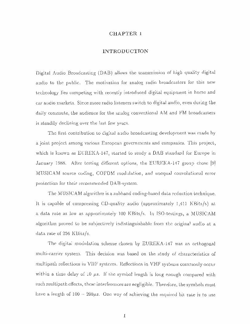
The digital modulation scheme chosen by EUREKA-147 was an orthogonal
multi-carrier system. This decision was based on the study of characteristics of
multipath. reflections in VHF systems. Reflections in VHF systems commonly occur
within a time delay of 10 µs. If the symbol length is long enough compared with
such multipath effects, these interferences are negligible. Therefore, the symbols must
have a length of 100 — 200µs. One way of achieving the required bit rate is to use
1

2
Figure 1.1 Notch caused by Multipath Interference
many orthogonal carriers in parallel to transmit the data. This technique introduces a
second multipath interference protection into the system; namely, frequency diversity.
The multipath reflections normally introduce a notch into the frequency spectrum, as
displayed in Fig. 1.1. If more carriers are employed, the effects of this narrow-band
notch are reduced.
The channel coding of the EUREKA-147 system is a convolutional code with
a soft decision Viterbi decoder [9]. The coding rate varies according to the relative
subjective importance of the audio frame from 1/4 to 3/8 with an effective coding
rate of 1/2.
So, why not to adapt this standard in the United States?
There are some differences between the U.S. and European broadcasting
systems. In Europe, most stations broadcast using public facilities. Hence the public
broadcasters can reach many common listeners. In the United States, broadcasters
have to compete in the advertisement market. Therefore, the number of listeners
automatically determines the advertising revenues. The EUREKA-147 system puts
5-16 broadcasters into one carrier group. This mandatory grouping conflicts with the
competition existing between stations in the United States. The second drawback

3
is that the EUREKA-147 standard requires an available bandwidth of approxi-
mately 50MHz for the DAB in the United States. This bandwidth is unavailable in
today's crowded frequency spectrum. The European countries solved this problem
by assigning different frequencies (e.g., unused TV channels) to different countries.
This causes receivers to be more complex than a simple radio receiver with a common
frequency band for all countries. Therefore, the task is to establish a system that
combines the transmission properties of the European system, while considering the
bandwidth limitations of the United States. Currently, different R&D companies
are working on this new technology. The first group of candidate systems are being
presently tested by the FCC. There is still a need for new ideas to improve these
systems.
This thesis examines different transmission techniques for AM and FM DAB.
The transmission of digital audio data in-band on-channel can be established by
using phase modulation techniques. The normal AM-receiver does not make use of
the phase information. Therefore, the digital data is phase encoded and a special
receiver recovers the information. Since the conventional receiver uses non coherent
reception techniques, the transmission is not disturbed. The F1\4 DAB discussed
in this thesis is using either a AM--modulation on the FM signal or a direct spread
spectrum signal beneath the analog FM. The AM transmission uses the amplitude
for adding the digital audio information. Since the conventional FM receivers don't
recover any amplitude information, they are unaffected by this technique. In case of
the DSSS the disturbing effects of the analog FM signal have to he reduced. Therefore
we will present some excision techniques capable of excising multiple interferences.
On exciser uses the Binomial Gaussian Window filter to excise the interferences. The
filter function is adapted to the special needs of the spectrum and a excision margin
ensures that the excision is stopped when a optimal point is reached.

CHAPTER 2
SPREAD SPECTRUM THEORY
2.1 Spread Spectrum Systems
Spread spectrum systems were first used for military communication purposes. These
communication systems must be resistant against possible unintended receivers.
They should have a low probability of intercept, and high protection against
distortions caused by natural and artificial sources, such as noise and jamming.
All of these system requirements can be solved if the signal is represented by a
noise-like wide-band signal through the channel. In this case the bandwidth of the
signal is much wider than the original data spectrum. This increased bandwidth
requirement is of minor concern for military applications. But it causes some
problems in commercial communications systems, where the bandwidth and power
are the main concerns. We will focus on a commercial application of spread spectrum
techniques in this thesis.
2.1.1 The Advantages of Using Spread Spectrum Systems
The basic idea of spread spectrum systems is to extend the data bandwidth in order
to gain protection against distortion or to provide multi-user access to the channel.
This bandwidth extension is realized by multiplying the data bits with a spreading
sequence. The spreading sequences are introduced later in this chapter. The length
of such a sequence N is called the chip rate. The chip duration is Tc = Td/N, where Td
is the data bit length.
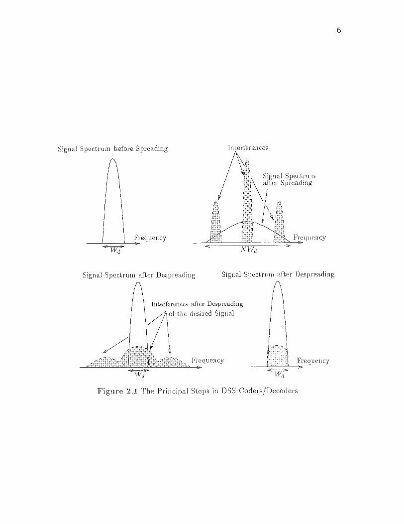
2.1.1.1 Interference Rejection
The advantages of spreading for interference rejection is displayed in Figure 2.1.
The DSSS transmitter spreads the data sequence d1 where (d1 E {-1,1} ,
4

5
VI) and therefore its bandwidth by multiplying it with the spreading sequence
c (c E { -1, 1} , for i = 1,..N ). During transmission the channel adds noise n
and other interferences j 1 . At the receiver side, the received signal r is expressed as
The receiver multiplies the received signal with a properly synchronized version of
the spreading sequence c. The length-N pseudonoise (PN) spreading code has the
energy, c c' = = N. The decision variable is given by,
This shows that the despreading operation spreads the interfering signals while
recovering the data. This spread of the interferences causes a significant loss of inter-
fering power at the demodulator. Therefore, the data recovery is much less likely to
produce errors than without spreading. This reduction of interferences is expressed
in the process gain of a spread spectrum system. If the data d1 has significant power
within Wd = 1/Td , and we are chipping it with a sequence of length N = Td/Tc , where d
Tc is the bit duration of the spread signal, then the despreading operation causes an
interference of bandwidth W1 to be spread over NWI. This means that the ratio
of the original interference power to the interference power after despreading within
the data bandwidth is given as
where G is called the processing gain.
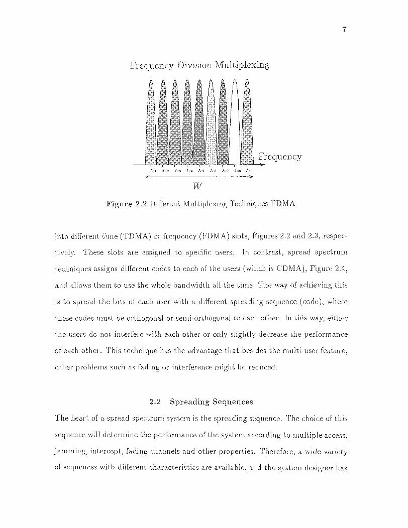
2.1.1.2 Multiple-User Access
The second advantage of spread spectrum systems is the possibility of having multi-
users on the same channel. Conventional transmission techniques split the channel
6
Figure 2.1 The Principal Steps in DSS Coders/Decoders
7
Frequency Division Multiplexing
Figure 2.2 Different Multiplexing Techniques FDMA
into different time (TDMA) or frequency (FDMA) slots, Figures 2.2 and 2.3, respec-
tively. These slots are assigned to specific users. In contrast, spread spectrum
techniques assigns different codes to each of the users (which is CDMA), Figure 2.4,
and allows them to use the whole bandwidth all the time. The way of achieving this
is to spread the bits of each user with a different spreading sequence (code), where
these codes must be orthogonal or semi-orthogonal to each other. In this way, either
the users do not interfere with each other or only slightly decrease the performance
of each other. This technique has the advantage that besides the multi-user feature,
other problems such as fading or interference might be reduced.
2.2 Spreading Sequences
The heart of a spread spectrum. system is the spreading sequence. The choice of this
sequence will determine the performance of the system according to multiple access,
jamming, intercept, fading channels and other properties. Therefore, a wide variety
of sequences with different characteristics are available, and the system designer has

Time Division Multiplexing
Figure 2.3 Different Multiplexing Techniques TDMA
Code Division Multiplexing
Figure 2.4 Different Multiplexing Techniques CDMA
8
9
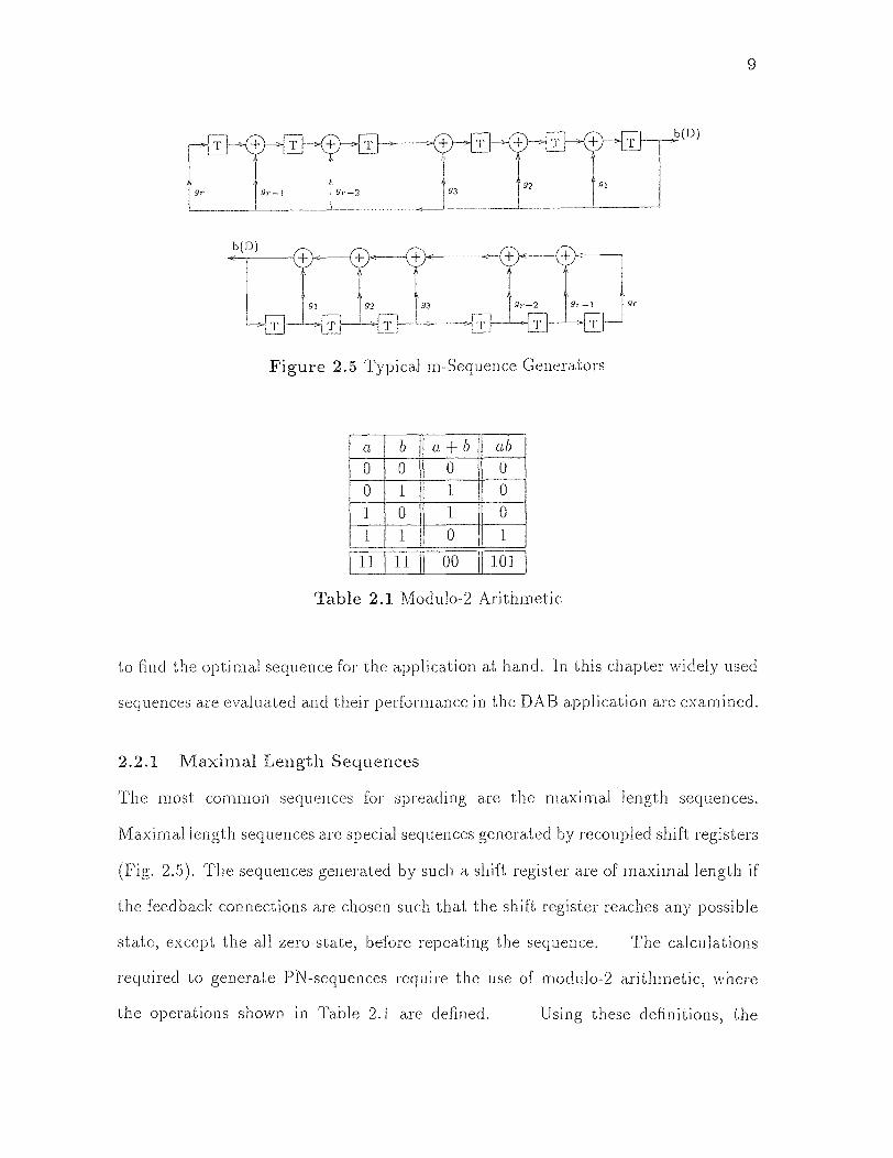
Figure 2.5 Typical m-Sequence Generators
a b a+b ab
0 0 0 0
0 1 1 0
1 0 1 0
1 1 0 1
11 11 00 101
Table 2.1 Modulo-2 Arithmetic
to find the optimal sequence for the application at hand. In this chapter widely used
sequences are evaluated and their performance in the DAB application are examined.
2.2.1 Maximal Length Sequences
The most common sequences for spreading are the maximal length sequences.
Maximal length sequences are special sequences generated by recoupled shift registers
(Fig. 2.5). The sequences generated by such a shift register are of maximal length if
the feedback connections are chosen such that the shift register reaches any possible
state, except the all zero-state, before repeating the sequence. The calculations
required to generate PN-sequences require the use of modulo-2 arithmetic, where
the operations shown in Table 2.1 are defined. Using these definitions, the
10
mathematical description of such a generator polynomial is given as [25]
Here, the D-operator represents the unit delay, while the exponent refers a multiple of
delay. The coefficients {gi} are either 1 or 0 and represent, the feedback connections.
The output b(D) of such a generator is described by
If the length of such a binary m-sequence is N = 2' — 1, the maximal length, the
polynomial is called a primitive polynomial. These primitive polynomials are of
special importance, since the sequences generated by them have desired properties.
The polynomials are given in their octal representation. For applications in a DAB-
system, three of these properties are of special interest.
1. In maximal length sequences, the number of ones is one more than the
number of zeros. The number of ones in a sequence of length N is
1/2(N + 1).
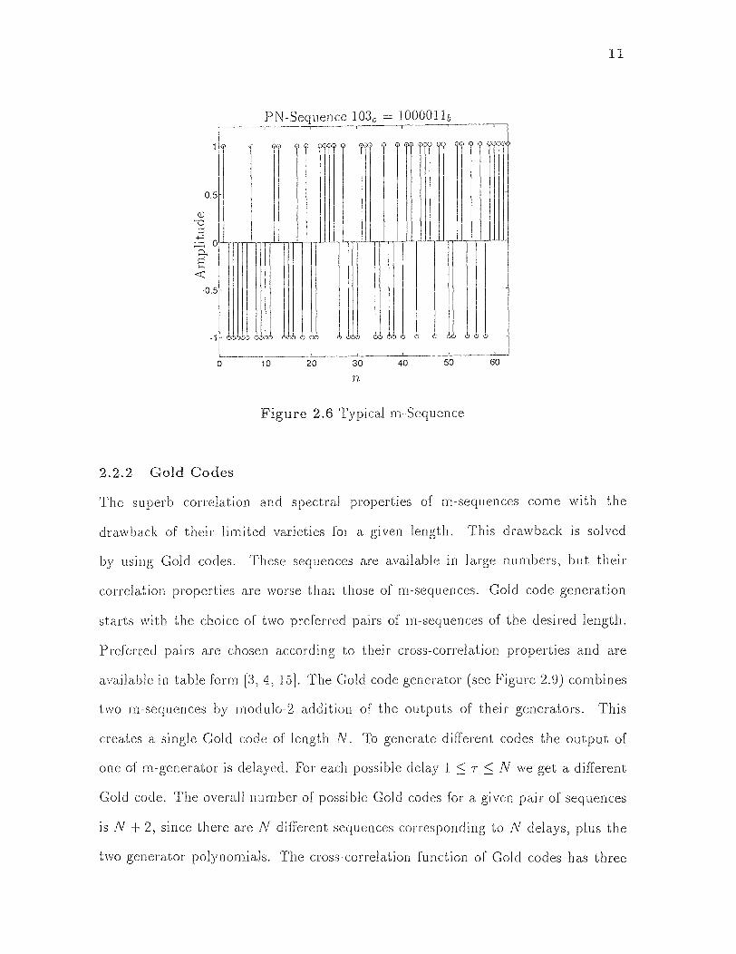
2. The periodic autocorrelation function Ob(k) of the sequence (Figure 2.8)
is two-valued and is given by
where an = (-1)bn as defined in [24].
3. The discrete Fourier transform of maximal length sequences is two-valued
and constant for all non-zero frequencies (Figure 2.7).
Since the search for these m-sequences is difficult., generator polynomials are
available in table forms [5, 15, 25]. The polynomials are given in their octal represen-
tations in those tables. The conversion into a binary number provides the coefficients
for the generator polynomial gi.
11
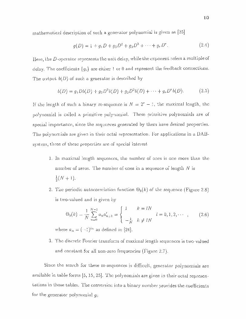
Figure 2.6 Typical m-Sequence
2.2.2 Gold Codes
The superb correlation and spectral properties of m-sequences come with the
drawback of their limited varieties for a given length. This drawback is solved
by using Gold codes. These sequences are available in large numbers, but their
correlation properties are worse than those of m-sequences. Gold code generation
starts with the choice of two preferred pairs of m-sequences of the desired length.
Preferred pairs are chosen according to their cross-correlation properties and are
available in table form [3, 4, 15]. The Gold code generator (see Figure 2.9) combines
two m-sequences by modulo-2 addition of the outputs of their generators. This
creates a single Gold code of length N. To generate different codes the output of
one of m-generator is delayed. For each possible delay 1 ≤ T ≤ N we get a different
Gold code. The overall number of possible Gold codes for a given pair of sequences
is N 2, since there are N different sequences corresponding to N delays, plus the
two generator polynomials. The cross-correlation function of Gold codes has three
Figure 2.7 Fourier Transform of a Typical m-Sequence
Autocorrelation Function of PIN-Sequence
Figure 2.8 Autocorrelation Function of a Typical m-Sequence
12
13
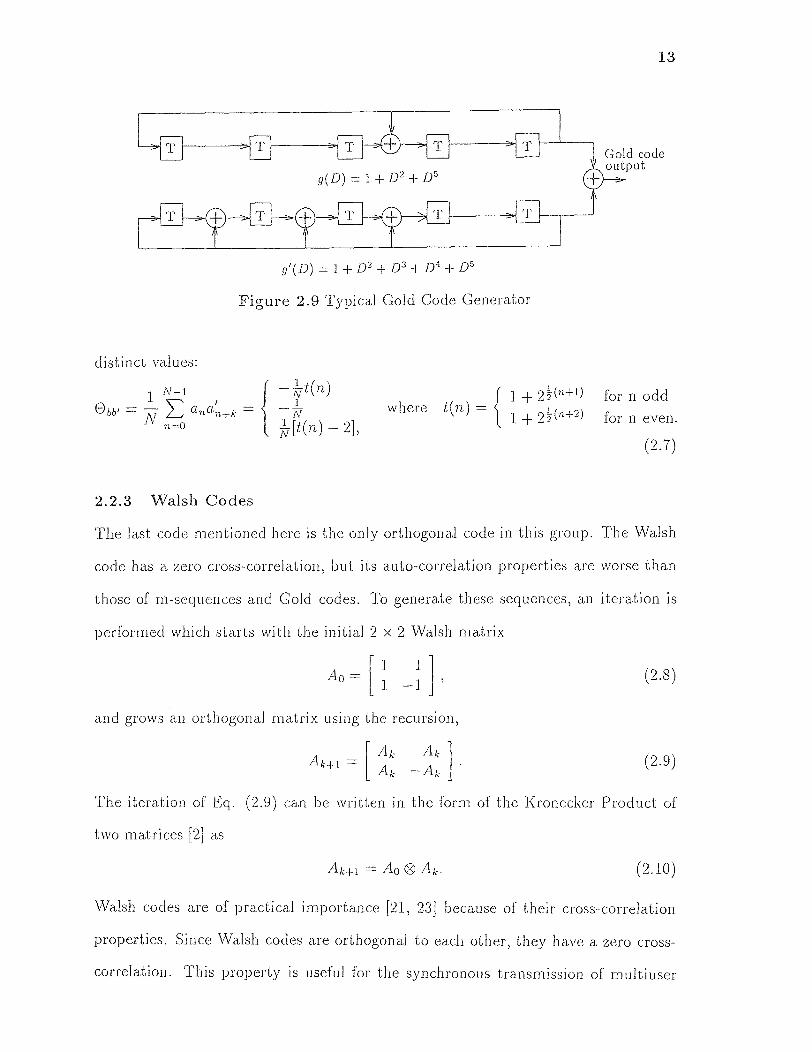
Figure 2.9 Typical Cold Code Generator
2.2.3 Walsh Codes
The last code mentioned here is the only orthogonal code in this group. The Walsh
code has a zero cross-correlation, but its auto-correlation properties are worse than
those of m-sequences and Gold codes. To generate these sequences, an iteration is
performed which starts with the initial 2 x 2 Walsh matrix
The iteration of Eq. (2.9) can be written in the form of the Kronecker Product of
two matrices [2] as
Walsh codes are of practical importance [21, 23] because of their cross-correlation
properties. Since Walsh codes are orthogonal to each other, they have a zero cross-
correlation. This property is useful for the synchronous transmission of multiuser
14
data. For DAB, this property can be used to extend the data rate of the DSSS-
system. Using Gold codes, the inter-user interference increases with the number of
simultaneously transmitting users. This is because of the small but non-zero cross
correlation between codes. Walsh codes do not cause any inter-user interference.
Finally, it should be mentioned that Walsh codes have much higher sidelobes of their
autocorrelation function. This can cause problems for multipath reception.

CHAPTER 3
DAB PROBLEM SCENARIOS
The newly developed Digital Audio Broadcasting technologies aim to fit the new
digital data into the already occupied analog radio spectra. Therefore the new digital
service is limited by already established analog audio broadcasting channels. Because
of that, we review AM and FM transmission techniques in the following sections.
3.1 AM Channels
AM broadcasting is normally used today for low audio quality information services.
The audio bandwidth for AM services is restricted to 5kHz, but some receivers may
reduce this bandwidth even further. This is done to reduce noise and interference
from neighboring channels. The RF bandwidth for AM transmission is restricted to
20kHz. The goal of a DAB system operating on AM channels is to provide a better
digital audio quality within this narrow bandwidth, without disturbing the existing
AM transmissions. In this section we present the fundamentals of. AM transmission.
Later we add a DAB-signal to it.
3.1.1 The AM Transmitter
The AM broadcasters transmit both sidebands and the carrier. This AM signal is
generally generated by multiplying the message signal with the sinusoidal carrier.
This can be written as [8]
where Ac is the carrier amplitude, fc the carrier frequency, ka the amplitude sensi-
tivity and m(t) the audio signal (message). For all of our calculations we assume
15

16
Figure 3.1 Envelope Detector
|kam(t)| < 1, for all t. The transmitter might mix this signal to the desired RF-
frequency. Since the mixing operation is transparent to the signal, we will skip this
and assume that it is performed without any significant error at both the transmitter
and receiver side. The frequency domain representation of an AM signal is given as
where M(f) is the spectrum of the baseband message signal. The overall power of
AM signal is expressed as
3.1.2 The AM Receiver
For the demodulation of the received AM signal, there are two basic techniques
available; coherent and noncoherent detection. We will first cover the two common
noncoherent detection techniques, square law detection and envelope detection,
before explaining coherent demodulation.
3.1.2.1 Envelope Detection
The simplest way of demodulating the AM signal is the envelope detector (Fig. 3.1).
The envelope detector rectifies the received AM signal,

17
Figure 3.2 Input and Output of the Envelope Detector
where n(t) is AWGN, and uses a low pass filter to recover the audio signal. The time
constants in this realization (Fig. 3.1) have to be adjusted such that
Here W is the bandwidth of the analog audio signal. In the ideal case, the mathe-
matical description of the output signal of an envelope detector is given as
where nc(t) is the in-phase component of narrow-band additive white Gaussian noise.
3.1.2.2 Square Law Detector
The second noncoherent demodulation technique, the square law detector, squares
the incoming signal according to Equation (3.8) and uses a low pass filter of
bandwidth W to recover the audio message
18
The output of the squarer y(t) can be rewritten as
The desired signal a2A2ckam(t) is recovered at the output of with a low pass filter. The
energy of a2A2ck2am2(t) within the message bandwidth W is negligible if |kam(t)| <<
1 for all t.
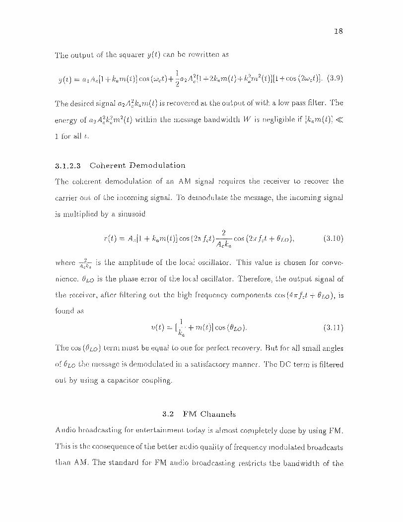
3.1.2.3 Coherent Demodulation
The coherent demodulation of an AM signal requires the receiver to recover the
carrier out of the incoming signal. To demodulate the message, the incoming signal
is multiplied by a sinusoid
where A k. is the amplitude of the local oscillator. This value is chosen for conve-
nience. θLO is the phase error of the local oscillator. Therefore, the output signal of
the receiver, after filtering out the high frequency components cos (47r fct + Ow), is
found as
The cos (θLO) term must be equal to one for perfect recovery. But for all small angles
of θLO the message is demodulated in a satisfactory manner. The DC term is filtered
out by using a capacitor coupling.
3.2 FM Channels
Audio broadcasting for entertainment today is almost completely done by using FM.
This is the consequence of the better audio quality of frequency modulated broadcasts
than AM. The standard for FM audio broadcasting restricts the bandwidth of the
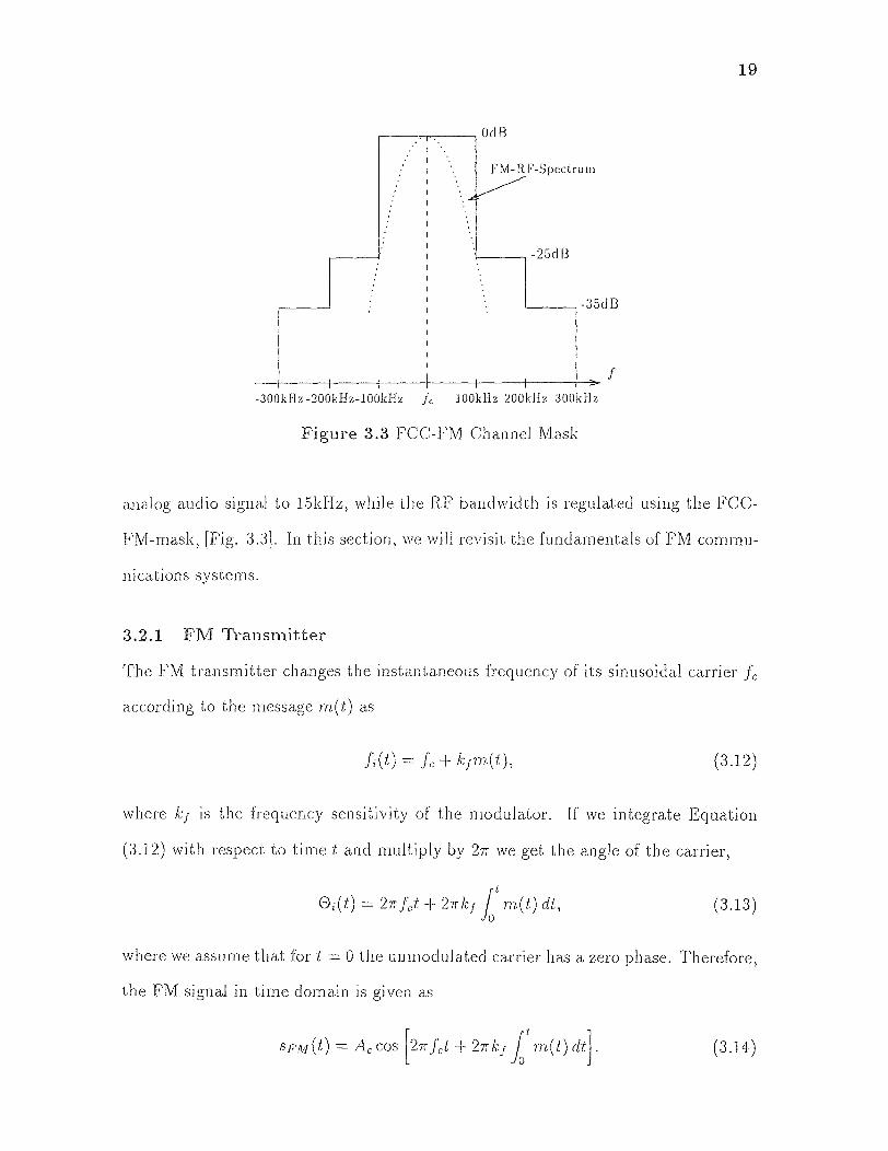
19
Figure 3.3 FCC-FM Channel Mask
analog audio signal to 15kHz, while the RF bandwidth is regulated using the FCC-
FM-mask, [Fig. 3.3]. In this section, we will revisit the fundamentals of FM commu-
nications systems.
3.2.1 FM Transmitter
The FM transmitter changes the instantaneous frequency of its sinusoidal carrier fc
according to the message m(t) as
where k f is the frequency sensitivity of the modulator. If we integrate Equation
(3.12) with respect to time t and multiply by 27 we get the angle of the carrier,
where we assume that for t = 0 the unmodulated carrier has a zero phase. Therefore,
the FM signal in time domain is given as
20
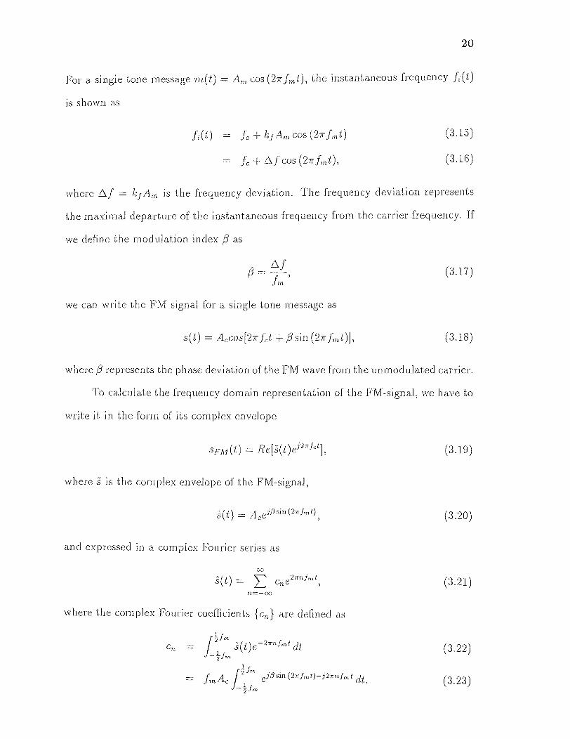
For a single tone message m(t) = Am cos (27r fmt), the instantaneous frequency fi (t)
is shown as
where Al = k f Am is the frequency deviation. The frequency deviation represents
the maximal departure of the instantaneous frequency from the carrier frequency. If
we define the modulation index ᵦ as
we can write the FM signal for a single tone message as
where β represents the phase deviation of the FM wave from the unmodulated carrier.
To calculate the frequency domain representation of the FM-signal, we have to
write it in the form of its complex envelope
where s is the complex envelope of the FM-signal,
and expressed in a complex Fourier series as
where the complex Fourier coefficients {cn} are defined as

21
For x = 2π fmt , this integral has the form of the nth order Bessel function of the first
kind and argument ᵦ ,
Some of the Bessel functions are plotted in Figure 3.4. The coefficients are expressed
as cn = AcJn(β ). Using the Bessel Functions we can rewrite equation (3.19) as
follows
Hence the Fourier transform of this signal is found as
3.2.2 FM Receiver
The FM receiver has to recover the audio data from the received frequency modulated
signal. Therefore, it is necessary to have a circuit that changes the amplitude linearly
with the frequency around the carrier. The most common demodulator is the PLL
demodulator. The PLL demodulator tracks the changes of the signal frequency and
produces an output voltage proportional to the frequency change necessary to track
the signal.
3.2.2.1 The PLL
The PLL is a negative feedback control circuit. The main components of a PLL
circuit are shown in Figure 3.5. For our calculations it is important that the
VCO is adjusted such that the output frequency for zero input is exactly the carrier
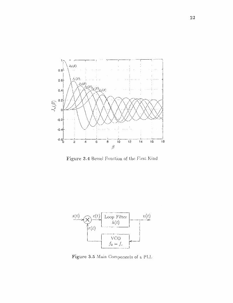
Figure 3.4 Bessel Function of th.e First Kind
22
Figure 3.5 Main Components of a PLL

23
frequency of the FM signal with a phase shift of 2. The FM signal s(t) can be written
as
where the Sine function is due to the phase shift of a and
The output signal of the VCO, r(t), is found as
where
and Av is the amplitude of the VCO output signal. The constant is the frequency
sensitivity of the VCO. The output of the multiplier e(t) can be written as
Defining
the output; of the loop filter v(t) can be written as
Recognizing that ϕe(t) can be written as
taking the first derivative with respect to t and replacing v(t) with Eq. (3.37) gives
24
In Eq. (3.39), the constant K0 = 2πAvAc/2 If the phase error ϕe(t) is equal to zero, the
PLL is said to be in phase lock. In this operation mode, we can simplify the system
by replacing
Now we can write a linear model for the PLL circuit as
Taking the Fourier Transform of Eq. (3.41), we can write
Introducing the loop transfer function L(f) as
we are able to rewrite Фe(f) as
In this equation, we see that Фe(f) 0 for IL(f)I >> 1. Rewriting the output V(f)
in terms of Фe(f ) results in
Substituting Фe(f ) by its equivalent in Eq. (3.44),
This can be approximated for |L(f)| >> 1 by
In the time domain, Eq. (3.47) can be written as
25
Thus, provided that |L(f)| >> 1 for all frequencies of interest, we may model the PLL
as a differentiator with the input scaled by 1/2πkv. Therefore, the PLL demodulator
for FM signals can be written as
where we substituted Eq. (3.30) into Eq. (3.48).
3.3 Digital Modulation Techniques
3.3.1 Binary Phase Shift Keying
Binary phase shift keying (BPSK) is a common, simple form of modulation used
for the transmission of digital signals [16]. In binary phase shift keying the carrier
is shifted in phase according to the data signal. Hereby the phase is able to take on
two distinct values separated by a phase difference of AO = 7r. For a transmitted
power of Ps = 0.5A2c, the BPSK signal can be written either as
If we convert the digital data stream d(t) into a bipolar signal, which can take on
either 1 or —1 values, we can write the BPSK signal as
At the receiver side, the carrier has to be recovered without any significant
phase error. Then, the demodulation is done by using synchronous demodulation
and an integrate-and-dump circuit. The output of the synchronous demodulator in
the absence of noise is given by
where Ochannel is the phase shift caused by the run-time delay of the transmission
channel. This signal is fed into the integrator that is controlled by a hit synchronizer.
26
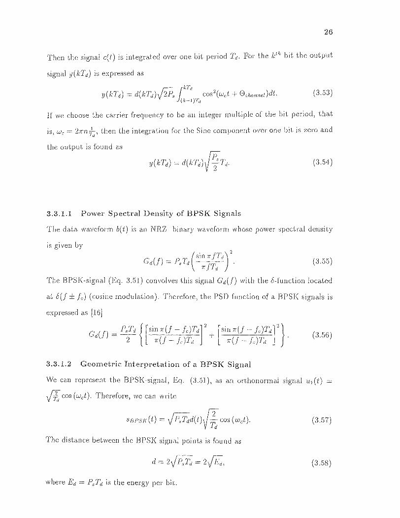
Then the signal c(t) is integrated over one bit period T. For the Oh hit the output
signal y(kTd ) is expressed as
If we choose the carrier frequency to be an integer multiple of the bit period, that
is, w, = 2πn 1/Td, then the integration for the Sine component over one bit is zero and
the output is found as
3.3.1.1 Power Spectral Density of BPSK Signals
The data waveform b(t) is an NRZ binary waveform whose power spectral density
is given by
'The BPSK-signal (Eq. 3.51) convolves this signal Gd (f) with the 8-function located
at δ(f ±fc ) (cosine modulation). Therefore, the PSD function of a BPSK signals is
expressed as [16]
3.3.1.2 Geometric Interpretation of a BPSK Signal
We can represent the BPSK-signal, Eq. (3.51), as an orthonormal signal u1(t) = Td
cos (wet). Therefore, we can write
The distance between the BPSK signal points is found as
where Ed =Td is the energy per bit.
27
Figure 3.6 Geometric Representation of a BPSK Signal
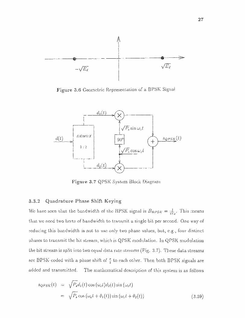
Figure 3.7 QPSK System Block Diagram
3.3.2 Quadrature Phase Shift Keying
We have seen that the bandwidth of the BPSK signal is BBpsK = 2Td This means .
that we need two hertz of bandwidth to transmit a single bit per second. One way of
reducing this bandwidth is not to use only two phase values, but, e.g., four distinct
phases to transmit the bit stream, which is QPSK modulation. In QPSK modulation
the bit stream is split into two equal data rate streams (Fig. 3.7). These data streams
are BPSK-coded with a phase shift of z to each other. Then both BPSK signals are
added and transmitted. The mathematical description of this system is as follows
28
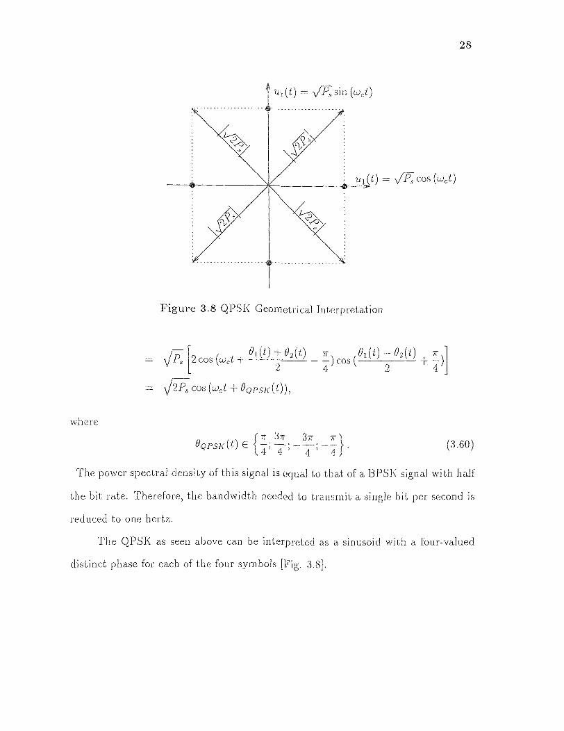
Figure 3.8 QPSK Geometrical Interpretation
The power spectral density of this signal is equal to that of a BPSK signal with half
the bit rate. Therefore, the bandwidth needed to transmit a single bit per second is
reduced to one hertz.
The QPSK as seen above can be interpreted as a sinusoid with a four-valued
distinct phase for each of the four symbols [Fig. 3.8].

CHAPTER 4
VARIOUS FREQUENCY EXCISERS
4.1 Transform Domain-Based Excisers
Linear block transforms are widely used for engineering applications. The DCT
is the international decomposition standard for audio and video compression. The
DFT is the most common transform for signal processing applications. In contrast to
these fixed transforms, the KLT makes use of the statistical properties of the signal.
It is the optimal decomposition of a signal for a given square transform size and signal
statistics. The frequency behavior of block transforms is restricted by the transform
size. All block transforms suffer from the limited time-frequency localization of their
transform bases. Filter banks or subband transforms overcome this drawback. The
length of the transform basis (filters) can be chosen independent from the number
of subbands or basis functions. Therefore, fine tuning of the transformation filters
(basis) according to the special needs of the application is possible [17, 18, 20].
Recently, it is well recognized that the block transforms and subband transforms are
only special cases of the Generalized Linear Transforms (GLT).
4.1.1 Introduction to Generalized Linear Transforms
The maximally decimated regular M-band PR-QM F structure, shown in Figure 4.1,
decompose the signal into M equal bandwidth subbands. The anti-aliasing filters
{hr(k)} reduce the bandwidth to M wide subbands. Therefore, decimation by a
factor of M is justified. In case of no intermediate processing, the upsampling by M
and interpolation with {gr (k)} perfectly recovers the input signal with a delay. In
this case the set of filters {hr (k)} and {gr (k)} are said to be perfect reconstruction.
This PR-condition property requires a stable and paraunitary transform matrix
29

30
11(z), such that
where d is some delay and I the identity matrix. H(z) is the paraconjugate of H(z).
The paraconjugate matrix is defined in [2, 22] as
where HH is the hermitian or conjugate transposed of H. This paraunitary condition
forces the analysis filters to satisfy the conditions
E
where {hr (k)} are the analysis filters and M 0. The synthesis filters {gr(k)} are
obtained from the analysis filters in a paraunitary system defined as
where N is the length of the filter. In case of block transforms, the conditions of
Eqs.(4.3) - (4.5) reduce to
since 11(z) is a square matrix of size M x M.
A different implementation of the maximally decimated equal M-band PR-
QMF structure can be achieved by reusing the same split for decomposing the
subband signals again. For a 2-band PR-QMF filter bank a regular hierarchical
tree is shown in Figure 4.2. The design of such a tree is much easier than that of
the M-band direct structure. In addition to that, the module structure simplifies

31
Figure 4.1 Maximally Decimated Equal M-Band PR-QMF Structure
the implementation. But as the number of levels increases, the aliasing in between
subbands becomes more significant. To process signals with different resolutions, the
dyadic tree (Fig. 4.3) can be used. Each additional level adds more details to the
signal, such that the original resolution is reached when all subbands are used. This
tree structure is widely used in multirate signal processing, such as video coding.
The irregular tree, shown in Figure 4.4 is the most flexible structure. According
to the special design requirements each level can use different filters and splits. For
a given, fixed signal characteristic this tree structure is able to perform an optimal
decomposition, fitting all spectral constraints.
4.1.2 Regular Subband Exciser
The regular tree subband structures (Fig. 4.2) can be used as a frequency exciser
[12]. The received signal is decomposed into M equal bandwidth subbands. These
subbands are checked for their energy contents. Thereby, the subbands containing
significant amount of interference will have the highest energy levels. These subbands
are discarded and the synthesis stage recovers the excised signal. The use of equal
bandwidth subbands is required for this application. Since the exact locations of

32
Figure 4.2 A Regular Subband Tree and Equal Bandwidth 8-Band Spectrum
Figure 4.3 A Dyadic Subband Tree and Unequal Bandwidth 4-Band Spectrum
Figure 4.4 An Irregular Subband Tree and Unequal Bandwidth 6-Band Spectrum

33
Figure 4.5 The Progressive Optimization Algorithm [18]
interferences is unknown, all possible bands have to be treated equally to ensure
constant performance for all frequency location of interferences.
Designing such filterbanks can be done by searching for a prototype, e.g. 2-
band PR-QMF filter, and reusing it according to the desired tree-structure. Better
performance can be achieved by designing the tree using the progressive optimization
technique [18]. This technique assures the best performance for tree structured
filterbanks. The design algorithm is illustrated in Figure 4.5. The first step designs
an optimal set of filters for the first stage of the desired tree structure. The next
step searches for the second stage filters of the tree such that the product filters are
optimal under the design constrains. This step is repeated until the desired number
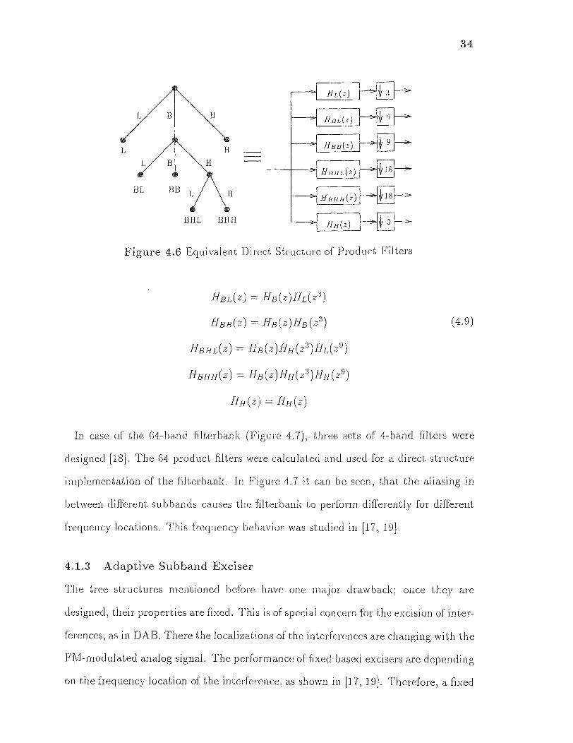
of stages reached. The product filters for a filterbank can be calculated as follows,
for Figure 4.6,
34
Figure 4.6 Equivalent Direct Structure of Product Filters
In case of the 64-band filterbank (Figure 4.7), three sets of 4-band filters were
designed [18]. The 64 product filters were calculated and used for a direct structure
implementation of the filterbank. In Figure 4.7 it can he seen, that the aliasing in
between different subbands causes the filterbank to perform differently for different
frequency locations. This frequency behavior was studied in [17, 19].
4.1.3 Adaptive Subband Exciser
The tree structures mentioned before have one major drawback; once they are
designed, their properties are fixed. This is of special concern for the excision of inter-
ferences, as in DAB. There the localizations of the interferences are changing with the
FM-modulated analog signal. The performance of fixed based excisers are depending
on the frequency location of the interference, as shown in [17, 19]. Therefore, a fixed

35
Figure 4.7 64-Band Filterbank Frequency Response
transform can not perform well. The excision of the FM-interferences requires the
adaptation of a decomposition structure to the spectral unevenness of the signal.
This can be done, since the data-signal is a wide band signal spreaded in frequency,
while the interference is localized in frequency. Therefore, evaluating the spectral.
unevenness of the received signal will localize the interference.
One common measure for the spectral unevenness is the energy compaction of
a transform [2]
where σ2x is the input variance and {σ2i} are the subband variances. The adaptive
frequency exciser utilizes an adaptive subband transform based on a tree structuring
algorithm [1, 17, 19]. The tree structuring algorithm checks the spectral unevenness
of the incoming signal for two possible splits, the 2- or 3-band decompositions. This
36
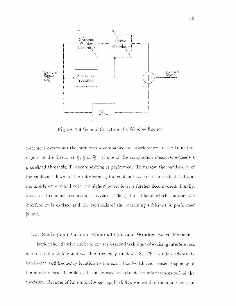
Figure 4.8 General Structure of a Window Exciser
treatment overcomes the problems accompanied by interferences in the transition
regions of the filters, at π/2, π/3 or 2π/3. If one of the compaction measures exceeds a
predefined threshold T, decomposition is performed. To narrow the bandwidth of
the subbands down to the interference, the subband variances are calculated and
the interfered subband with the highest power level is further decomposed. Finally,
a desired frequency resolution is reached. Then, the subband which contains the
interference is excised and the synthesis of the remaining subbands is performed
[2, 22].
4.2 Sliding and Variable Binomial-Gaussian Window-Based Exciser
Beside the adaptive subband. exciser a second technique of excising interferences
is the use of a sliding and variable frequency window [14 This window adapts its
bandwidth and frequency location to the exact bandwidth and center frequency of
the interferences. Therefore, it can be used to extract the interferences out of the
spectrum. Because of its simplicity and applicability, we use the Binomial-Gaussian

37
Figure 4.9 Gaussian Window Time and Frequency Response
window for the excision. In addition to that, a Binomial-Gaussian function will
be an appropriate choice because of its smooth frequency response, and excellent
frequency localization [6]. The general structure of a frequency window excises is
shown in Figure 4.8. By calculating the DFT of the received signal, the inter-
ference localizer examines the frequency localization of the interferences and their
bandwidths. Using this data, the Gaussian window generator calculates the corre-
sponding filter coefficients. The cosine modulator modulates the filter to the desired
frequency (Figure 4.9). Filtering the signal with this linear phase FIR filter and
subtracting from the received signal excises the interference. A comparator compares
the excised signal with the excision margin and decides whether the excision goal is
already achieved. If not, the operation is repeated. The Gaussian approximation of
the Binomial coefficients [6] is used to estimate the Gaussian pulse, it can be written
38
This Binomial sequence reassembles the Gaussian pulse successfully for large N. The
factor of (1/2)N-1 normalizes the Binomial function's frequency response to one at
w = 0. Therefore, for a practical implementation of the Binomial-Gaussian function,
can be used to replace the Gaussian pulse [6]
where the constant A is chosen so as to normalize the energy of the function to unity
over [-π, π]. The bandwidth of the filter (a) is determined by the variance of the
Gaussian pulse. But the bandwidth in frequency is also related to the duration in.
time. Therefore, a closed-form relation is necessary between the duration (N) and
bandwidth of the filter. This can be approximated by N = 4/σ2 as shown in [6].
For practical purposes, it is advised to restrict the length of the filter to maximum
N = 513 taps. The modulation of the lowpass Gaussian window is performed using
cosine modulation [2, 22]. The interference localizer estimates the center frequency
wc of the interference. The window generator modulates the low-pass window f (k)
to the desired position according to [2],
One important point by using this modulated filters is power normalization. If the
filters are normalized, the output can be directly subtracted form the delayed version
of the input. This normalization causes f(k) to be calculated as

39
where g(k) is the Gaussian lowpass filter and Eg is its energy. Eg can be calculated
as
The Gaussian filter can be written as [7]
The constant K can be calculated as follows
The normalization with Eq is based on the unity magnitude response of a filter 2σ
with bandwidth r. A filter with smaller bandwidth has to be normalized such that
its energy is equal to , where B is the Bandwidth of the filter. The simulation
results for this excises are presented in a later chapter.
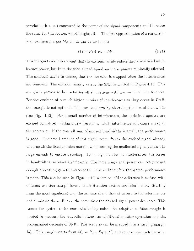
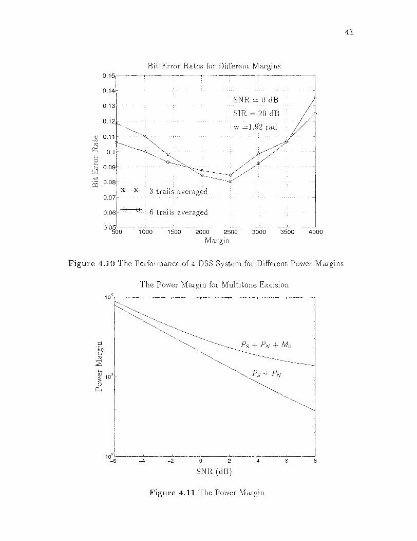
4.3 Power Margin in Multitone Excisers
In the case of multitone excision one significant concern is the tradeoff in between
further reduction of interferences and the decreasing desired signal power. This
results in a hit error rate performance curve shown in Figure 4.10. This curve has a
minimum point depending upon the number and power of the interferences, the noise
power, and the loss of signal bandwidth due to the excision. Therefore, a threshold
has to be found that takes this parameter into account. The received signal power
can be written as
where Ps is the transmitted signal power, PN the noise power, and P1 the interference
power. The summation ƩNK=1 [s(k)j(k) -I- s(k)n(k) + n(k)j(k)] is zero, if the received
signal components are orthogonal to each other. For practical applications, their
40
correlation is small compared to the power of the signal components and therefore
the sum. For this reason, we will neglect it. The first approximation of a parameter
is an excision margin ME which can be written as
This margin takes into account that the excisers mainly reduce the narrow band inter-
ference power, but keep the wide spread signal and noise powers minimally affected.
The constant M0 is to ensure, that the iteration is stopped when the interferences
are removed. The excision margin versus the SNR is plotted in Figure 4.11. This
margin is proven to be useful for all simulations with narrow band interferences.
For the excision of a much higher number of interferences as they occur in DAB,
this margin is not optimal. This can be shown by observing the loss of bandwidth
(see Fig. 4.12). For a small number of interferences, the undesired spectra are
excised completely within a few iterations. Each interference will cause a gap in
the spectrum. If the over all sum of excised bandwidths is small, the performance
is good. The small amount of lost signal power forces the excised signal already
underneath the fixed excision margin, while keeping the unaffected signal bandwidth
large enough to ensure decoding. For a high number of interferences, the losses
in bandwidths increases significantly. The remaining signal power can not produce
enough processing gain to overcome the noise and therefore the system performance
is poor. This can be seen in Figure 4.12, where an FM-interference is excised with
different excision margin levels. Each iteration excises one interference. Starting
from the most significant one, the excisers adapt their structure to the interferences
and eliminate them. But on. the same time the desired signal power decreases. This
causes the system to be more affected by noise. An adaptive excision margin is
needed to measure the tradeoffs between an additional excision operation and the
accompanied decrease of SNR . This scenario can be mapped into a varying margin
ME. This margin starts from ME = Ps + PN M0 and increases in each iteration
41
Figure 4.10 The Performance of a DSS System for Different Power Margins
Figure 4.11 The Power Margin
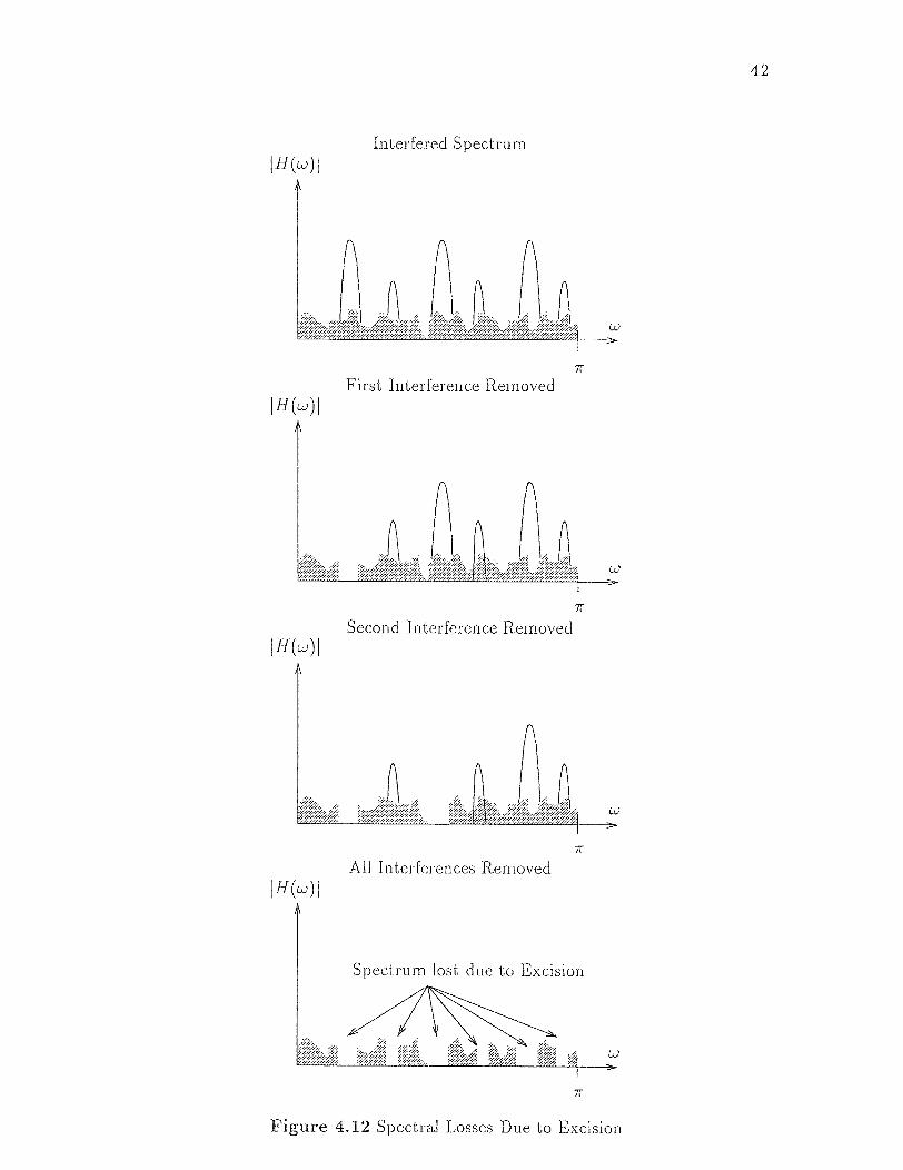
Figure 4.12 Spectral Losses Due to Excision
42

43
Figure 4.13 Improvement of Different Excision Margins
proportional to the lost bandwidth. The excision is performed until the overall signal
power is less than this margin. This leads to the expression for ME,
where Bi is the bandwidth of the i' excision-filter and K the number of interferences
excised. This excision margin model is based on the assumption, that the spreaded
signal. power is linearly distributed within [0,π]. In addition we assume that a loss
of Bk bandwidth will cause a decrease in spreading gain of π/Bk %. The performance
for different adaptive excision margins are shown in Figure 4.13 for single tone inter-
ferences.
44
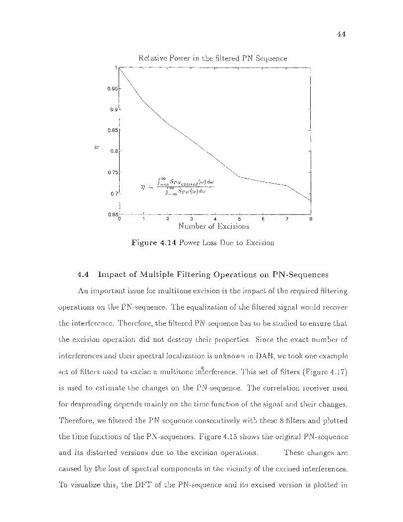
Figure 4.14 Power Loss Due to Excision
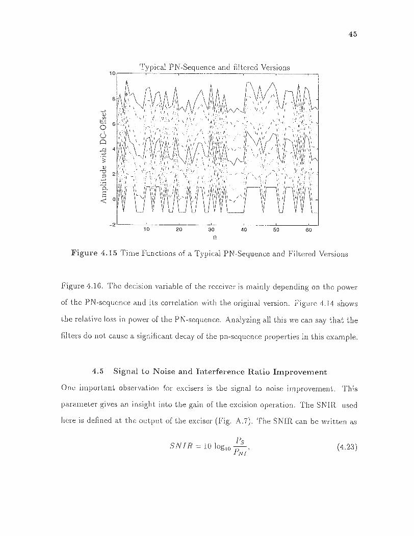
4.4 Impact of Multiple Filtering Operations on PN-Sequences
An important issue for multitone excision is the impact of the required filtering
operations on the PN-sequence. The equalization of the filtered signal would recover
the interference. Therefore, the filtered PN-sequence has to be studied to ensure that
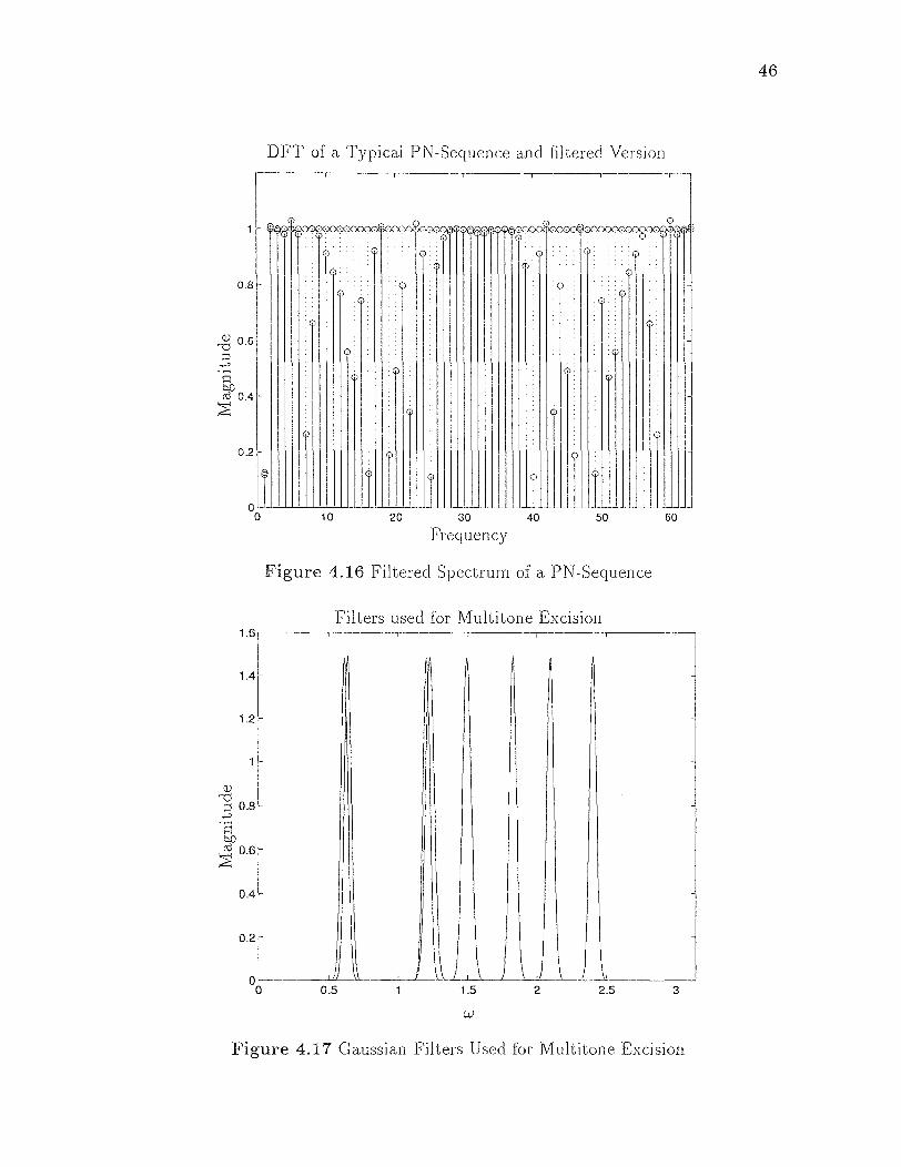
the excision operation did not destroy their properties. Since the exact number of
interferences arid their spectral localization is unknown in DAB, we took one example
set of filters used to excise a multitone interface. This set of filters (Figure 4.17)
is used to estimate the changes on the PN-sequence. The correlation receiver used
for despreading depends mainly on the time function of the signal and their changes.
Therefore, we filtered the PN-sequence consecutively with these 8 filters and plotted
the time functions of the PN-sequences. Figure 4.15 shows the original PN-sequence
and its distorted versions due to the excision operations. These changes are
caused by the loss of spectral components in the vicinity of the excised interferences.
To visualize this, the DFT of the PN-sequence and its excised version is plotted in
45
Figure 4.15 Time Functions of a Typical PN-Sequence and Filtered Versions
Figure 4.16. The decision variable of the receiver is mainly depending on the power
of the PN-sequence and its correlation with the original version. Figure 4.14 shows
the relative loss in power of the PN-sequence. Analyzing all this we can say that the
filters do not cause a significant decay of the pn-sequence properties in this example.
4.5 Signal to Noise and Interference Ratio Improvement
One important observation for excisers is the signal to noise improvement. This
parameter gives an insight into the gain of the excision operation. The SNIR used
here is defined at the output of the exciser (Fig. A.7). The SNIR can be written as
46
Figure 4.16 Filtered Spectrum of a PN-Sequence
Figure 4.17 Gaussian Filters Used for Multitone Excision
47
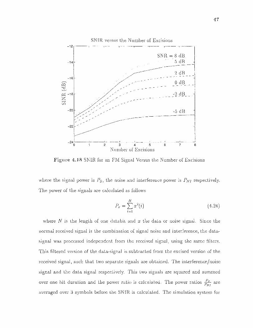
Figure 4.18 SNIR for an FM Signal Versus the Number of Excisions
where the signal power is Ps, the noise and interference power is PNI respectively.
The power of the signals are calculated as follows
where N is the length of one databit and x the data or noise signal. Since the
normal received signal is the combination of signal noise and interference, the data-
signal was processed independent from the received signal, using the same filters.
This filtered version of the data-signal is subtracted from the excised version of the
received signal, such that two separate signals are obtained. The interference/noise
signal and the data signal respectively. This two signals are squared and summed
over one bit duration and the power ratio is calculated. The power ratios Ps /P N1 are
averaged over 3 symbols before the SNIR is calculated. The simulation system for

48
the evaluation is shown in Figure A.7 and the table of parameters used for this
simulation are given in Table A.3.
Figure 4.18 shows the performance of the Gaussian window based exciser for
FM-interference versus the number of excisions. The simulation was repeated for
different noise levels, to visualize the affects of noise within the system. It can be
seen, that after 6-7 excisions the SNIR reaches a limit. This can be interpreted
as that the significant components are excised. From this point on the decrease in
interference is accompanied by a decrease of the energy of the PN-sequence.
CHAPTER 5
The DAB Transmission
5.1 The Requirements for In-Band On-Channel Transmission
The In-Band On-Channel transmission of the new DAB-service is restricted by
several practical considerations. Some of them are stated below to explain the
restrictions to meet in a design of a DAB-System [14].
5.1.1 FM Requirements
For the FM In-Band On-Channel transmission the following specifications are given:
the DAB-signal must be In-Band On-Channel, and not create perceptible
disruption to the analog FM signal
the DAB signal must fit within the existing FM bandwidth of 200kHz
the DAB signal must be 30dB below the analog M signal
the supportable data rate must be an aggregate 400kbits/ sec
the modulation format must be able to withstand multipath fading with the
following characteristics:
• 100kHz wide and 15dB deep for stationary reception
• 200kHz wide and 20dB deep for mobile reception
5.1.2 AM Requirements
For the AM In-Band On-Channel transmission the following specifications are given:
the DAB-signal must be In-Band On-Channel, and not create perceptible
disruption to the analog AM signal
49
50
the DAB signal must fit within the existing FM bandwidth of 20kHz
the DAB signal must be 35dB (co-channel) and 25dB (adjacent channel) below
the analog AM signal
the supportable data rate must be an aggregate in the range of 96-128kbits/sec
the modulation format must be able to withstand multipath fading with the
following characteristics:
• 100kHz wide and 15dB deep for stationary reception
• 200kHz wide and 20dB deep for mobile reception
5.2 DAB on FM
As we have seen in chapter 3, the FM-reception does not put any requirements on
the amplitude of the incoming signal. Furthermore, the practical receiver handles
amplitude related errors by slicing the incoming signal around zero. Using the
remaining zero crossings, the FM-signal is recovered with normalized amplitude.
A transmission scheme for this property will be discussed in the first part of this
chapter. The second part proposes a way of reducing the interfering affects of the
analog FM-signal to the digital separately transmitted signal for the case of DSSS-
DAB.
5.2.1 AM Modulation on FM
The first technique of transmitting digital audio on an FM-signal is to use a conven-
tional amplitude modulation. This technique makes use of the amplitude normal-
ization of FM-receivers. The data recovery can be easily managed using envelope
detection. A simple block diagram of such a receiver is shown in Figure 5.1. In this
transmission system the analog audio signal is M-modulated using the conventional
techniques. This FM-signal is then AM-modulated with the digital DAB-signal.

51
Figure 5.1 FM DAB Transmission System Block Diagram
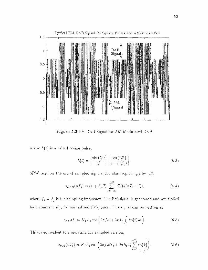
This composite signal is displayed in Figure 5.2. The FM-receiver can easily
recover the analog audio information by evaluating the zero crossings for demodu-
lation. The DAB-receiver will perform an envelope detection on the FM-DAB-signal.
The detector is unaffected by the FM-frequency changes, since these deviations are
negligible compared to the carrier frequency.
To evaluate the performance of the AM-modulated FM-DAB-System, a
simulation system was developed using Comdisco's SPW. The detailed simulation
parameter and simulation blocks are shown in the Appendix in Table A.1 and Figure
A.1.
5.2.1.1 Simulation of the System Transmitter
The transmitter for the DAB-transmission as an AM-modulated FM-signal is shown
in Figure A.2. The binary, bipolar, white data sequence d(t) is pulse shaped using
a raised cosine filter. The constant multiplier Ka is used to adjust the DAB-signal
power and AM modulation amplitude sensitivity ka. After adding the signal to one,
the DAB-signal is
52
Figure 5.2 FM DAB Signal for AM-Modulated DAB
where h(t) is a raised cosine pulse,
SPW requires the use of sampled signals, therefore replacing t by nTs
where fs = T, is the sampling frequency. The FM-signal is generated and multiplied
by a constant KJ for normalized FM-power. This signal can be written as
This is equivalent to simulating the sampled version,
53
These two signals are multiplied such that the transmitted signal s(t) or s(nTs) is
This signal is transmitted using a flat, additive white Gaussian noise channel.
5.2.1.2 Simulation of the Receiver
The receiver, shown in Figure A.3 splits the signal into two paths. The upper path
recovers the analog FM-audio signal while the DAB-signal is recovered in the lower
path. The received signal can be written as
Using r(t) as the input to the hard limiter, the output signal can be written as a
Fourier series [10]
This signal is filtered with a Butterworth bandpass filter to recover the sinusoidal
waveform, that can be written assuming optimal filtering as
The PLL locks onto this signal to demodulate the analog FM. The output of the
PLL is lowpass filtered and can be written as

54
The DAB path of the receiver first recovers the envelope of the FM-signal. This
signal can be written as,
To recover the bipolar digital data, it is necessary to subtract the mean, which is
done using a comb filter. This filter estimates the mean of the signal by averaging it
over a sliding time window. This mean estimate is then subtracted form the signal.
The comb-filter has a transfer function H (e-jw) as follows,
where N is the length of the sliding window. The output of the filter is
a scaled version of the input signal. To reduce the amplitude distortion, the filtered
signal is sampled and sliced around zero, to recover the digital data.
5.2.2 DSSS DAB in FM
The second technique of transmitting DAB digital data In-Band On-Channel is to
use a spread spectrum signal underneath the analog FM. This transmission scheme
makes use of the interference resistance of a spread spectrum system. To evaluate
the performance of the DSSS under an analog FM-signal, a simulation system was
developed using SPW. The main components of the system are shown in Figure
A.5. This system consists of a spread spectrum data source, a channel that adds the
interferences and noise, an exciser and a receiver for spreaded data. The additional
blocks take care of the bit error rate evaluation.
5.2.2.1 Simulation System for FM-DAB -I- Gaussian Noise Channel
The Data Generator is shown in detail in Figure A.2. It generates a white binary

55
data signal. This signal is converted into a bipolar signal and multiplied bit by bit
with the bipolar PN-sequence. Hereby, the sampling frequencies are chosen, such
that one data bit is replaced by the pn-sequence. This spreaded signal is degraded
by additive white Gaussian noise. In addition to that a❑ FM-signal is added to the
spreaded data. This SPW-block is shown in Figure A.6. The received signal can be
written as
where sFM is a vector of FM signal samples according to
Before decoding the digital data, the excision block has to reduce the interferences.
Therefore, a Binomial-Gaussian Window based exciser adapts a filter structure to
the spectral needs of the FM-signal and excises the main components of the FM
signal. The adaptive excision power margin is chosen according to Eq. (4.22). The
constant M0 is equal to 1000 for our simulations.
The output of the exciser for the 7-nth-data bit can be written as
where h(k) is the combined version of all used excision filters.
The Despreading is done using the same proper synchronized PS sequence
as used at the transmitter. The decoder block is shown in Figure A.11. After
multiplication with the PN sequence the decoder sums the samples of one data bit
56
and decides by evaluating the sign of the signal. The output of the summation
operation can be written as
where N is the length of the PN sequence and c(n) the PN sequence. The decision
is based on the sign of 4. The decoded data bit is then compared with the original
transmitted version. The error counter compares both signals and registers every
bit error occurring. If the desired number of bit errors occurred, the simulation is
stopped and the output file can be used for bit error calculation.
5.3 DAB on AM
Since the normal AM-receiver is using non-coherent demodulation techniques, one
way of transmitting digital data over an AM-channel is to use the phase of the carrier.
In this case, a receiver for the standard analog AM is unaffected, but a coherent DAB
receiver will easily demodulate the digital data. This system. configuration is shown
in Figure 5.3. The received signal can be written as
Od(t) in Eq. (5.24) represents the M-PSK-modulation. The reception is done in two
separated paths. The upper one recovers the analog data using any noncoherent
demodulation technique. Therefore, the output of the envelope detector is

57
Figure 5.3 DAB System (AM)
The digital data is recovered using coherent demodulation. The output of the hard
limiter can be written as a Fourier series [10]
Here 071(t) is the phase-error caused by the noise of the channel. The demodu-
lation with a proper synchronized Cosine generator moves the signal into baseband.
The integration over a bit-duration recovers the digital data. The high frequency
components will integrate to zero, since the bitlength should he chosen to he a
integer multiple of the carrier period. Therefore the decision variable λk for the
k th-bit is given by

CHAPTER 6
RESULTS
In this chapter the results for different simulations are given.
6.1 The Excision of Multitone Sinusoidal Interferences
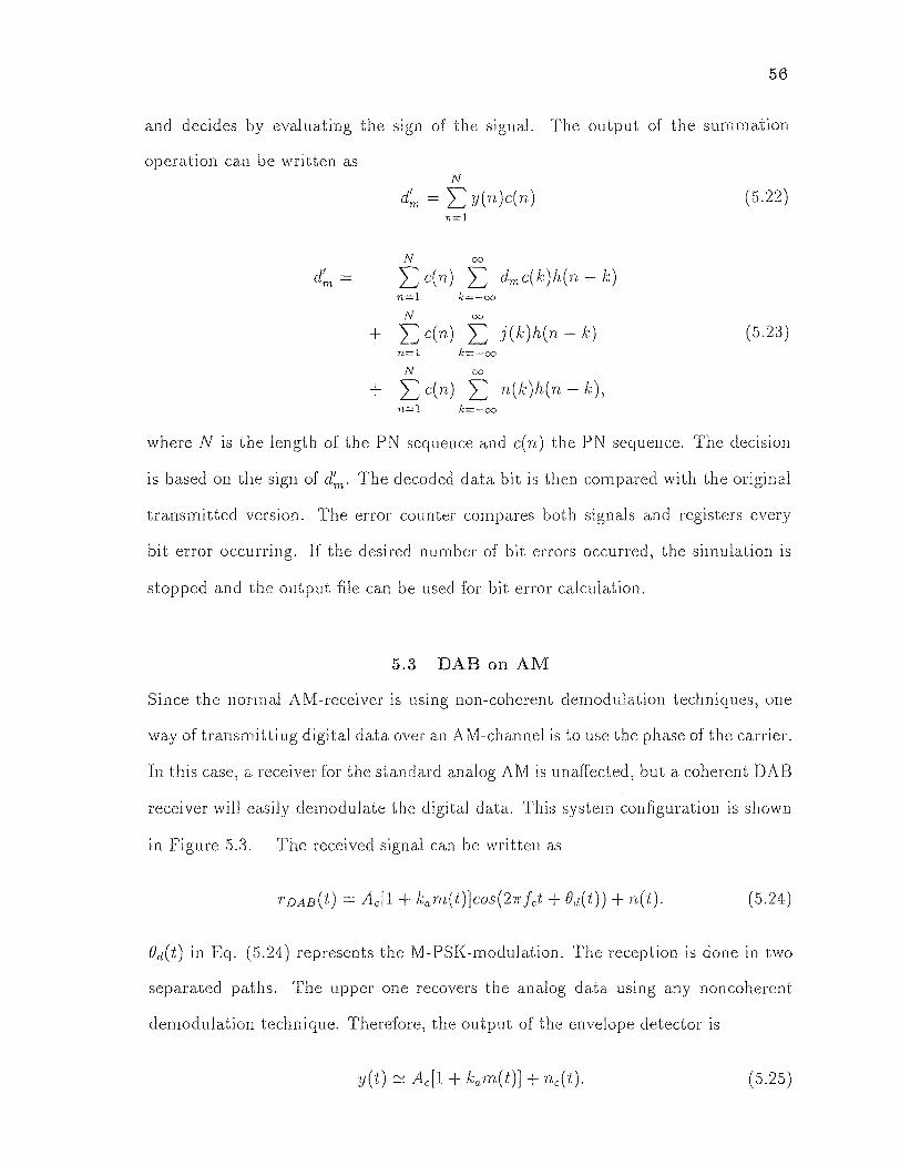
To estimate the performance of the Binomial-Gaussian Window-based exciser,
different numbers of sinusoidal interferences were used to disturb the signal. The
performance of the Exciser was evaluated for different number of bits used for the
excision. The parameters of the interference are given in Table 6.1. The over all
signal to interference ratio was held constant at SIR= —20dB The Bit error rate
Parameter
Frequency Amplitude
One Interference
0.1885 rad/sec 14.14
Two Interferences
0.1885 rad/sec 10.00
0.3770 rad/sec 10.00
Four Interferences
0.1885 rad/sec 7.071
0.3770 rad/sec 7.071
0.5655 rad/sec 7.071
1.0681 rad/sec 7.071
Table 6.1 The Simulation Parameters for the Multitone Interference Excision
for different signal to noise ratios is shown in Figure 6.1. To improve the performance
for more than one interference the bit error rate was evaluated for blocks of more
than one bit. Thereby, the performance was improved by increasing blocksize. A
plot of the bit error rate for 3 bit blocksize is given in Figure 6.2.
58
59
Figure 6.1 Performance of Gaussian Window-Based Exciser for a 63 Samples Window
Figure 6.2 Performance of Gaussian Window-Based Exciser for a 189 Samples Window
60
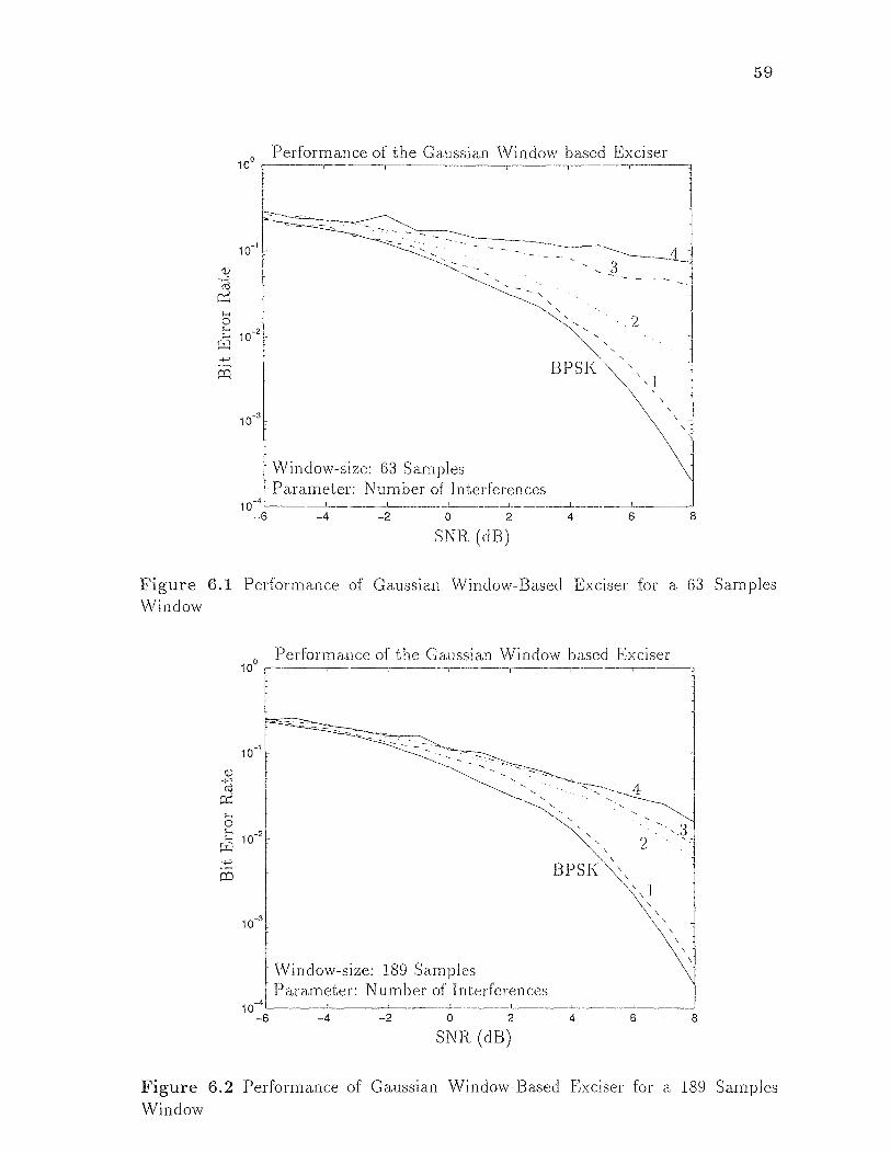
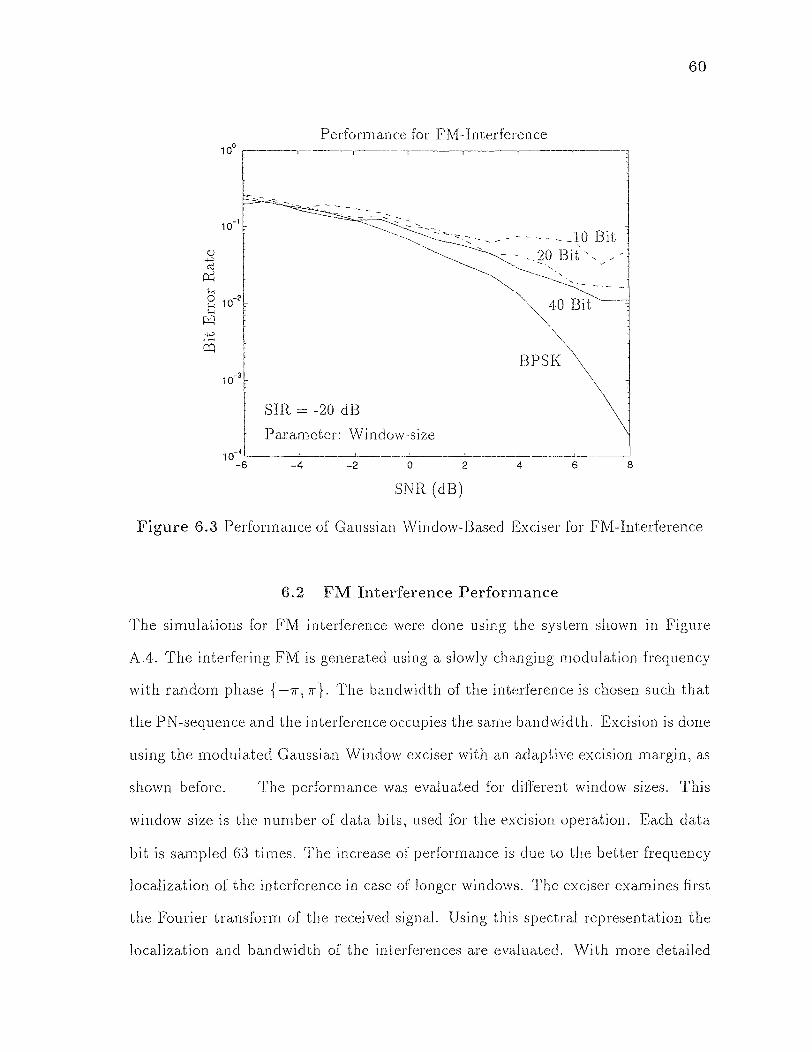
Figure 6.3 Performance of Gaussian Window-Based Exciser for FM-Interference
6.2 FM Interference Performance
The simulations for FM interference were done using the system shown in Figure
A.4. The interfering FM is generated using a slowly changing modulation frequency
with random phase {-π, π}. The bandwidth of the interference is chosen such that
the PN-sequence and the interference occupies the same bandwidth. Excision is done
using the modulated Gaussian Window exciser with an adaptive excision margin, as
shown before. The performance was evaluated for different window sizes. This
window size is the number of data bits, used for the excision operation. Each data
bit is sampled 63 times. The increase of performance is due to the better frequency
localization of the interference in case of longer windows. The exciser examines first
the Fourier transform of the received signal. Using this spectral representation the
localization and bandwidth of the interferences are evaluated. With more detailed
61
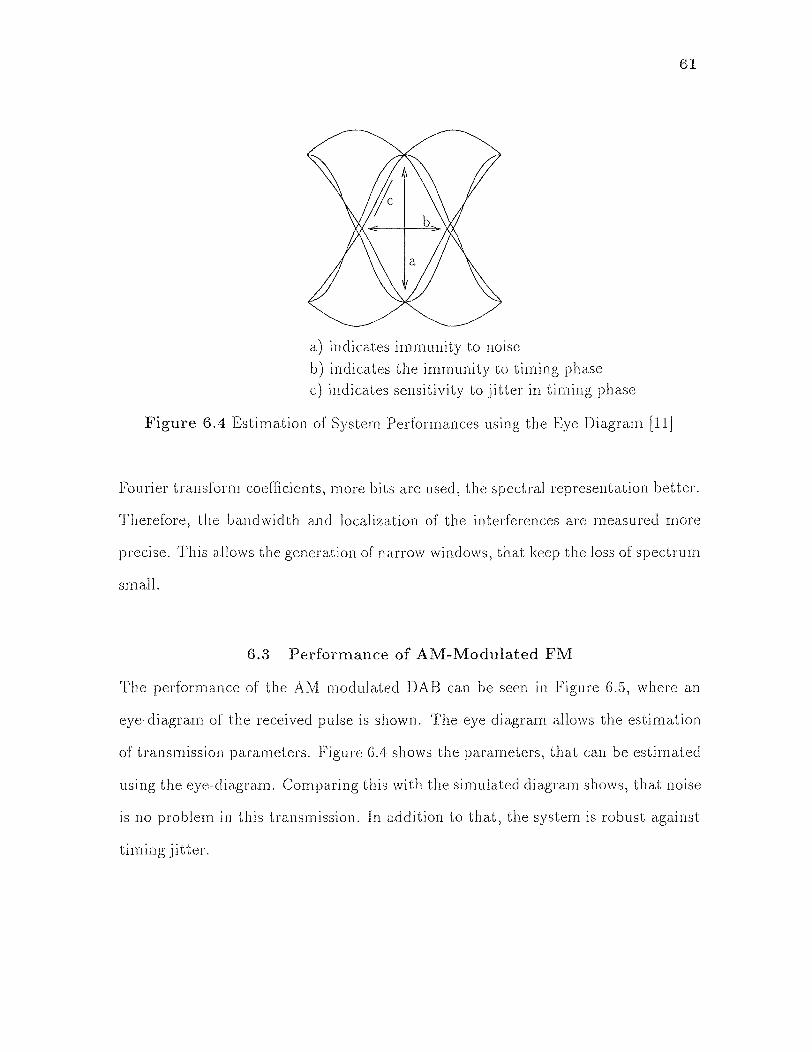
Figure 6.4 Estimation of System Performances using the Eye Diagram [11]
Fourier transform coefficients, more bits are used, the spectral representation better.
Therefore, the bandwidth and localization of the interferences are measured more
precise. This allows the generation of narrow windows, that keep the loss of spectrum
small.
6.3 Performance of AM-Modulated FM
The performance of the AM modulated DAB can be seen in Figure 6.5, where an
eye-diagram of the received pulse is shown. The eye diagram allows the estimation
of transmission parameters. Figure 6.4 shows the parameters, that can be estimated
using the eye-diagram. Comparing this with the simulated diagram shows, that noise
is no problem in this transmission. In addition to that, the system is robust against
timing jitter.

62
Figure 6.5 Eye Diagrams of the AM on FM-DAB System
CHAPTER 7
DISCUSSION AND CONCLUSIONS
In this thesis, we exploit the in-band on-channel transmission of digital audio data
for DAB applications. Several different transmission scenarios were employed and
simulated. In this chapter, we will summarize the work we have done and discuss the
results we established as well as the yet open questions, that have to be exploited in
future work.
The main focus of this work was the usage of excision techniques for the
direct sequence spread spectrum transmission of digital data and the exploration
of the problems and solutions for this kind of transmission. The transmission of
digital data underneath an FM signal using direct sequence spread spectrum trans-
mission techniques requires the reduction of the FM interference using excision
techniques. We developed and tested several excision algorithms and simulated their
performance. The Binomial-Gaussian window-based exciser was used for FM excision
because of its simplicity and implementability as well as its good performance. It
requires no previous knowledge of the received signal or its statistics. The excision.
goal, the reduction or elimination of interfering signals, can be specified using an
excision power margin that measures the energy of the remaining signal. If the
excised signal energy is below this threshold the excision is stopped and the signal
is decoded. The excision of interferences in DSSS performs very well for single or
several tone interferences. In the FM interference case, the excision of main inter-
ferences is not sufficient to establish an acceptable bit error rate. The reason is that
the repeated excision of interferences reduces the unaffected bandwidth. In addition
to that, the unexcised bandwidth is not interference free, in contrast to the single
tone case. The small but existing amount of interfering power, in addition to the
63
64
lost bandwidth, decays the receiver performance. The system performance can be
improved by extending the length of the window used for excision to several bits.
However, the bit error rate results still do not allow a stable transmission of digital
data underneath an FM signal.
The second approach to establish a digital transmission of audio data in-band
on-channel, exploit in this thesis, is the usage of a AM modulation on the FM-
signal. This approach holds a stable data transmission with a low bit error rate.
In addition, the interference between the new service and the analog transmission
is negligible. In contrast to the first approach, the digital data is unaffected by the
analog transmission and therefore no excision has to be performed.
The third transmission scheme is used for the AM-DAB. There, the phase
modulation of the carrier adds the new service to the analog signal. This transmission
scenario allows the two signals to be detected independently from one another.
Therefore, an interference reduction in the digital transmission, as well as in the
analog transmission, is not necessary. The bit error rate of the AM-DAB trans-
mission is only due to channel noise. Therefore it is capable of transmitting digital
audio data in-band on-channel.
7.1 Future Work
This thesis examined the digital audio transmission in-band on-channel for DAB
applications in the United States. Future research is necessary to fully exploit the
practical merits of the transmission techniques mentioned above. More realistic
channel scenarios have to be developed and examined. Attention has to be paid to
issues such as channel fading and multipath reception. These practical problems of
radio transmission in a mobile environment will require the use of more sophisticated
receiver structures e.g. equalizers. In addition, the synchronization of these receivers
to changing channel parameters and signal phases has to be exploited. Moreover

65
analytical research has to be done to rind optimal parameters for these problems.
Finally, the implementation of the best solution in hardware and measurements in
real environments will complete this work.

APPENDIX A
SIMULATION SYSTEMS
Parameter Value FM / DAB - Signal Source Data Bitrate 10 Bits/sec Data Sampling Frequency 1000 Hz Raised Cosine Filter (Order) 64 Taps Roll-Off Factor 0.8 Frequency Deviation 6 Hz/V Carrier Frequency 100 Hz Sampling Frequency 1000 Hz Audio Frequency 1 Hz Audio Sampling Frequency 1000 Hz Receiver PLL - Center Frequency 100 Hz PLL Loop Filter (Order) 1 PLL Loop Filter (Bandwidth) 10 Hz PLL VCO Constant 12 PLL Sampling Frequency 1000 Hz Mean Estimator (Window) 10000 Samples DAB - LP (Order) 20 DAB - LP (Passband) 12 Hz DAB - LP (Sampling Frequency) 1000 Hz
Table A.1 The Simulation Parameters for the AM on FM DAB System
66
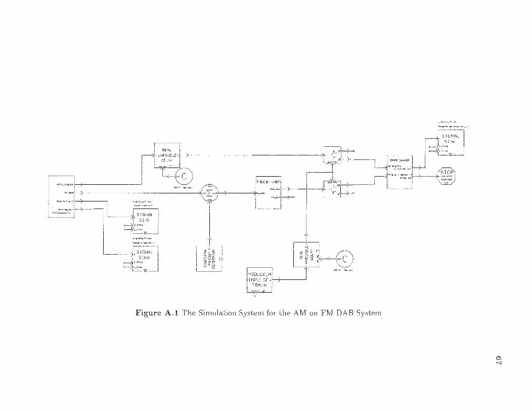
Figure A.1 The Simulation System for the AM on FM DAB System
67
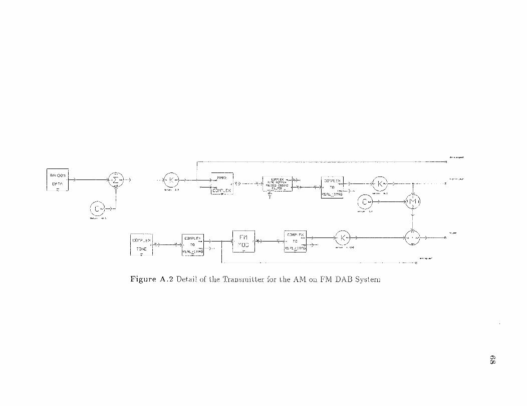
Figure A.2 Detail of the Transmitter for the AM on. FM DAB System
68
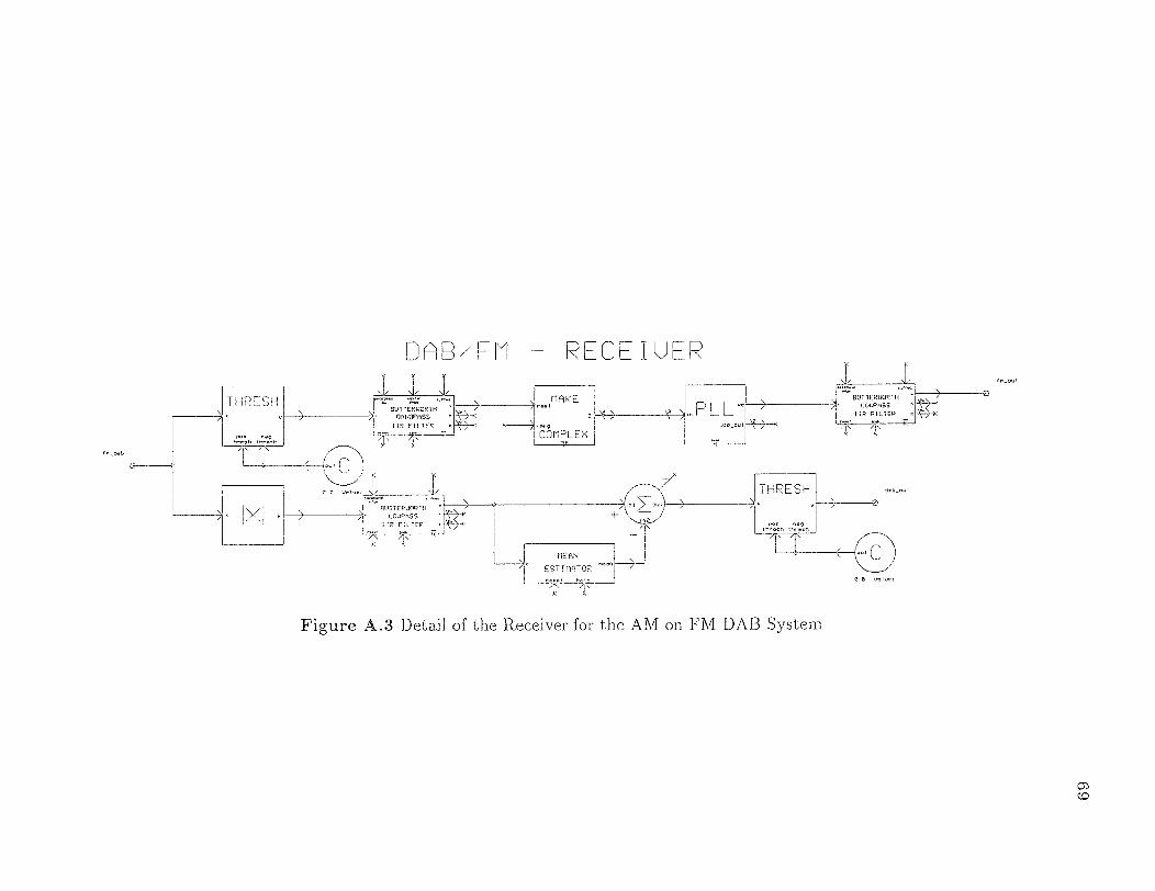
Figure A.3 Detail of the Receiver for the AM on FM DAB System
69

Figure A.4 The Simulation. System for Multitone Interference Cancellation

Parameter Value Signal Source Data Bitrate 1 Bits/sec Data Sampling Rate 63 Hz PN-Sequence Bitrate 1 Bits/sec PN-Sequence Sampling Rate 1 Hz Channel FM-Carrier Frequency 0 Hz FM-Frequency Deviation 20 Hz/Volt FM-Amplitude 14.14 Volt Message Frequency 2 Hz Message Amplitude 1 Volt Sampling Frequency 63 Hz
Table A.2 The Simulation System Parameters for Direct Sequence Spread Spectrum Digital Audio Broadcasting
71
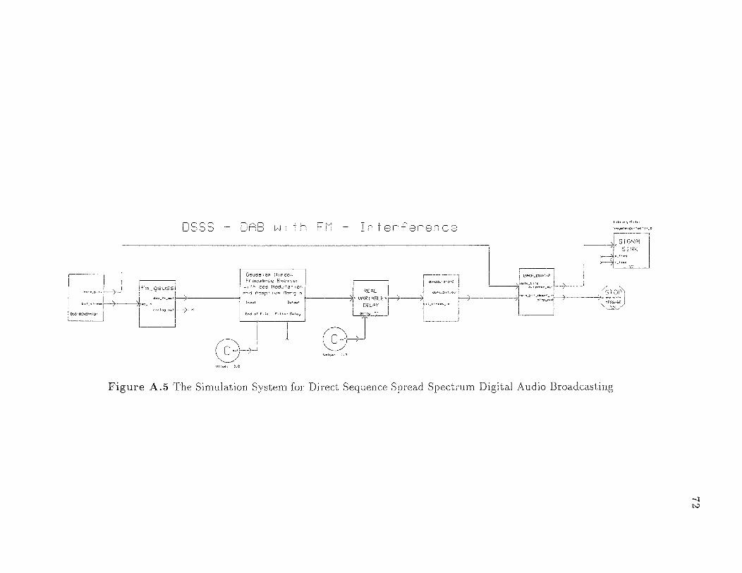
Figure A.5 The Simulation System for Direct Sequence Spread Spectrum. Digital Audio Broadcasting
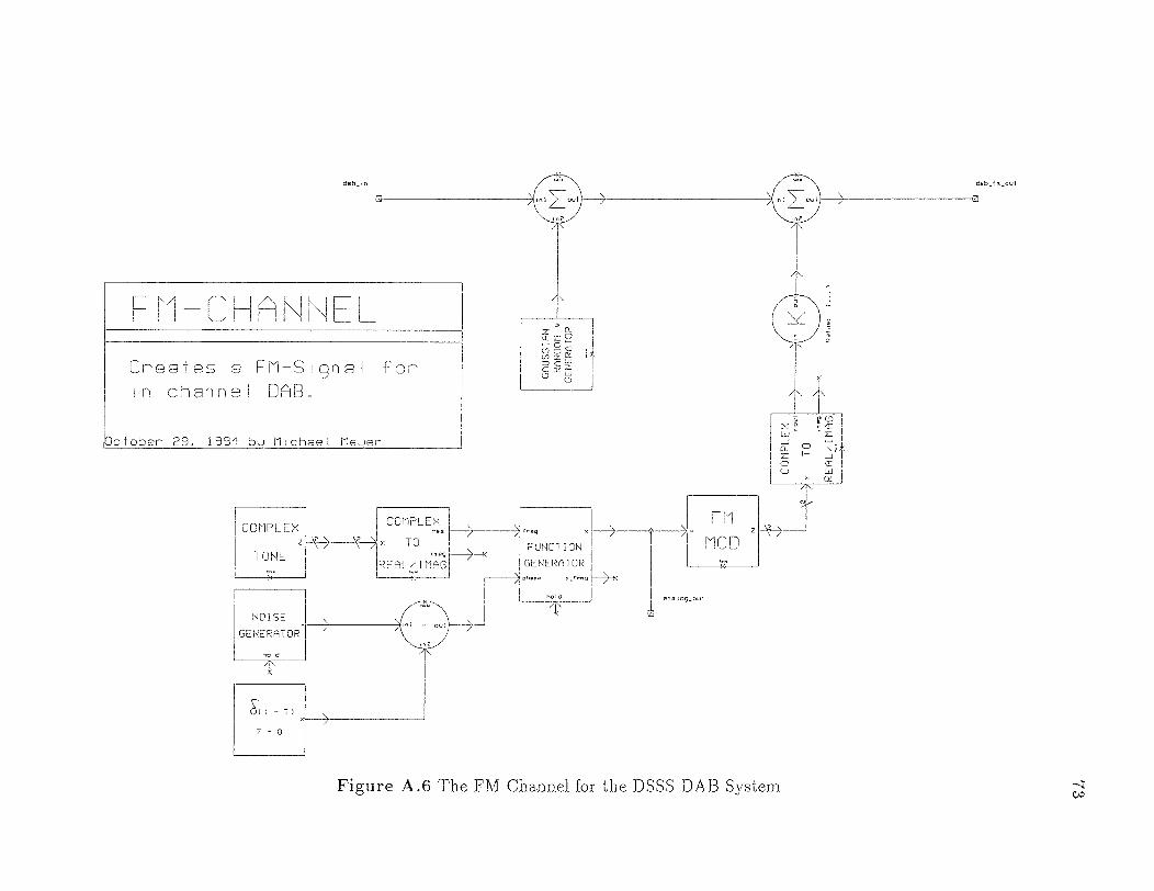
Figure A.6 The FM Channel for the DSSS DAB System
73
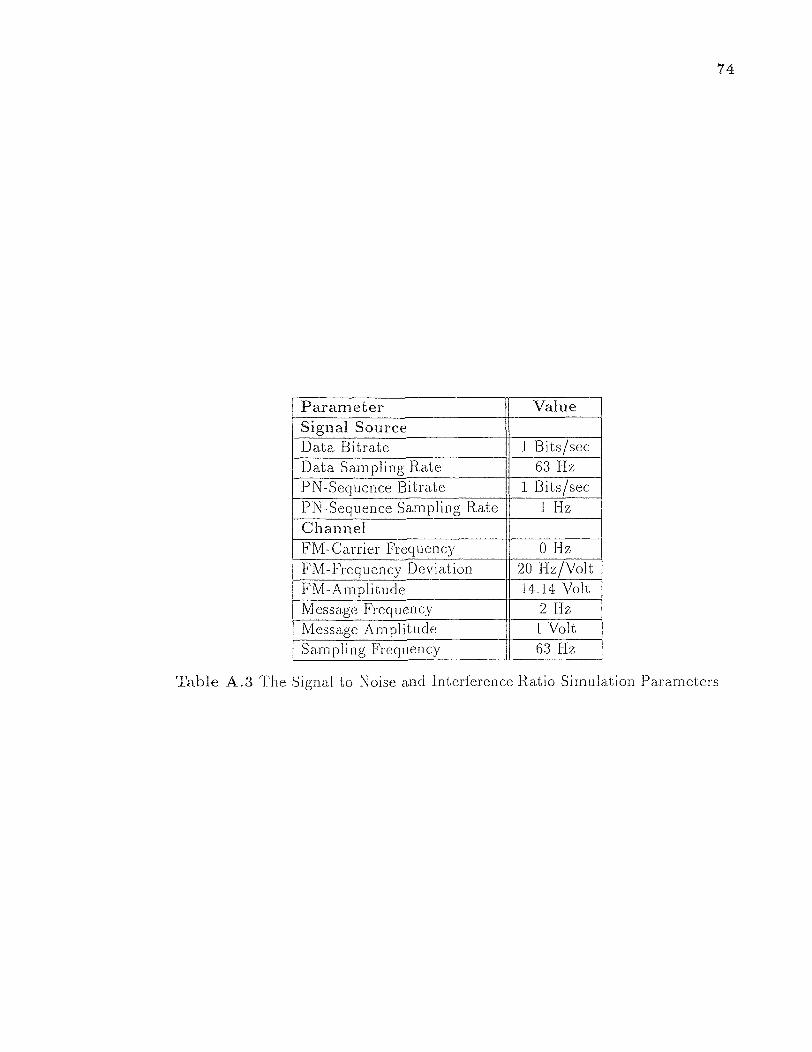
Parameter Value Signal Source Data Bitrate 1 Bits/sec Data Sampling Rate 63 Hz PN-Sequence Bitrate 1 Bits/sec PN-Sequence Sampling Rate 1 Hz Channel FM-Carrier Frequency 0 Hz FM-Frequency Deviation 20 Hz/Volt FM-Amplitude 14.14 Volt Message Frequency 2 Hz Message Amplitude 1 Volt Sampling Frequency 63 Hz
Table A.3 The Signal to Noise and Interference Ratio Simulation Parameters
74
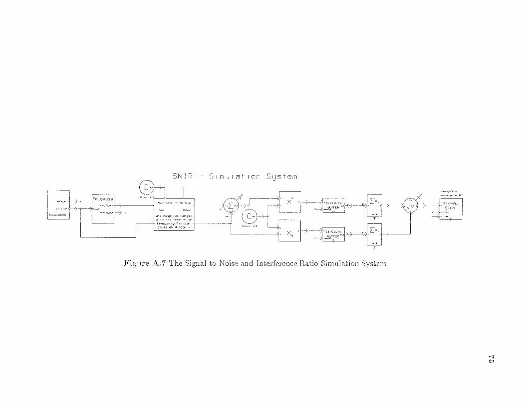
Figure A.7 The Signal to Noise and Interference Ratio Simulation System
75

Figure A.8 64-Band Subband Exciser System
76
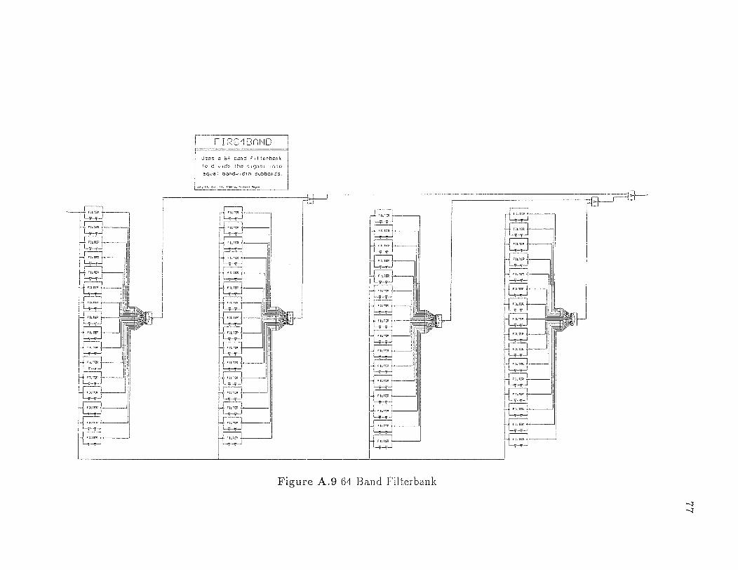
Figure A.9 64 Band Filterbank
77
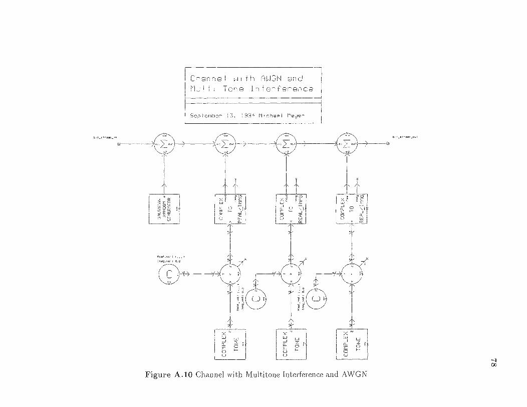
Figure A.10 Channel with Multitone Interference and AWGN
78

Figure A.11 DSS Demodulate]
79
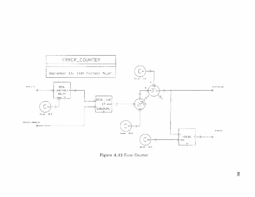
Figure A.12 Error Counter
80

Figure A.13 DAB on. AM Simulation System
81

Figure A.14 AM DAB Transmitter
82
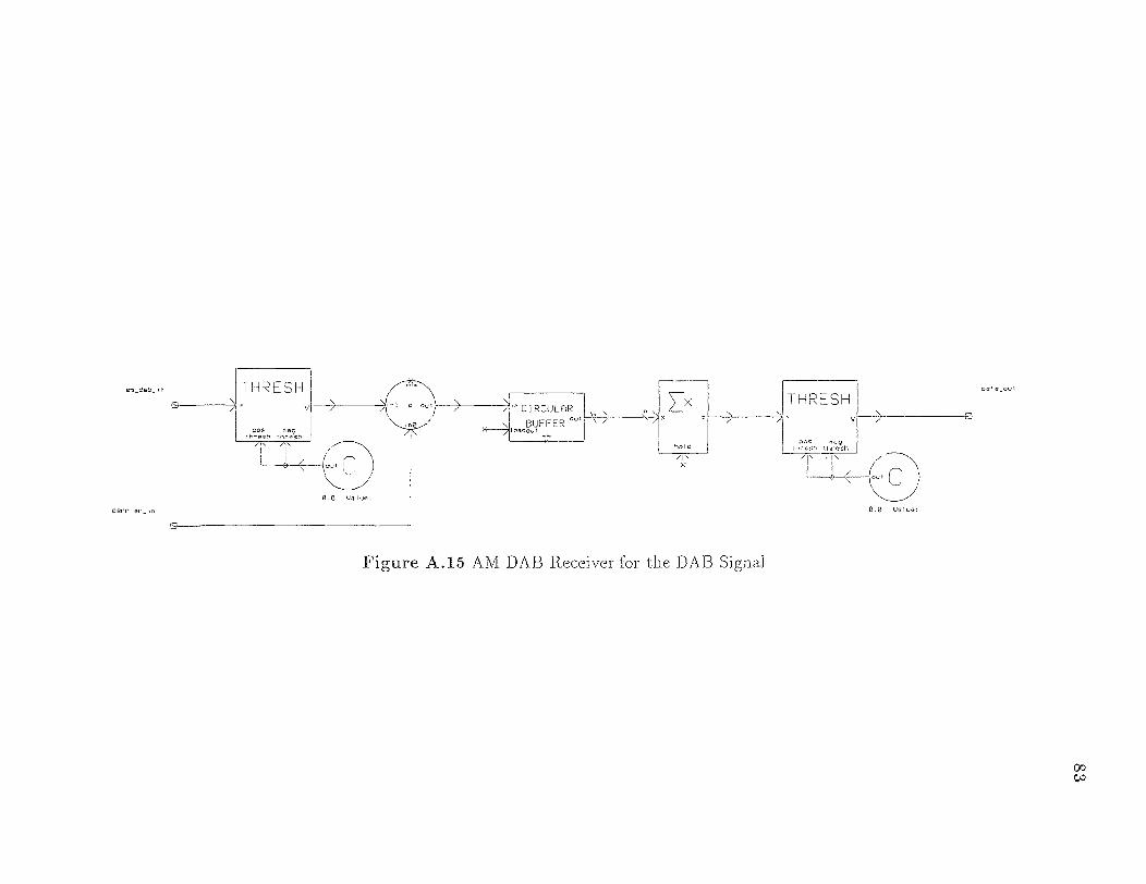
Figure A.15 AM DAB Receiver for the DAB Signal
83
REFERENCES
1 A N Akansu and Y. Liu, "On signal decomposition techniques," Optical
Engineering, pp. 912-920, July 1991.
2. A. N. Akansu and R. A. Haddad, Multiresolution Signal Decomposition, Transforms, Subbands, Wavelets, Academic Press, INC., San Diego, California, 1992.
3. R. C. Dixon, Spread Spectrum Systems, John Wiley & Sons, New York, second ed., 1984.
4. R. Gold, "Maximal recursive sequences with 3-valued recursive cross-correlation functions," IEEE Transactions on Information, January 1968.
5. S. W. Golomb et al., Shift Register Sequences, Aegean Parc Press, Laguna Hills, California, revised ed., 1982.
6. R. A. Haddad, "A class of orthogonal nonrecursive binomial filters," IEEE Transactions on Audio and Electroacoustics, pp. 296-304, December 1971.
7. R. A. Haddad, A. N. Akansu, and A. Benyassine, "Time-frequency local-ization in transforms, subbands, and wavelets: a critical review," Optical
Engineering, pp. 1411-1428, July 1993.
8. S. Haykin, Communication Systems, John Wiley & Sons, New York, New York, second ed., 1983.
9. D. L. W. Hinderks, "Digital audio broadcasting - current and future directions," in Applications of Subbands and Wavelets, NJIT, Department of Electrical and Computer Engineering, Center for Communications and Signal Processing Research, March 1994.
10. B. P. Lathi, Modern Digital and Analog Communication Systems, CBS College Publishing, New York, NJ, 1983.
11. E. A. Lee and D. G. Messerschmitt, Digital Communications, Kluwer Academic Publisher, Boston, second ed., 1994.
12. M. Medley, G. J. Saulnier, and P. Das, "Applications of the wavelet transform in spread spectrum communications systems," in Applications of Subbands and Wavelets, NJIT, Department of Electrical and Computer Engineering, Center for Communications and Signal Processing Research, March 1994.
13. M. Meyer, M. V. Tazebay, and A. N. Akansu, "A sliding and variable window based multitone excision for digital audio broadcast," submitted to IEEE International Symposium on Circuits and Systems, April 1995.
84

85
14. A. Polydoros, "In-band on-channel digital audio broadcast: Review of existing proposals and further suggestions," Report No: S0492-1, April 1992.
15. D. V. Sarwate and M. B. Pursley, "Crosscorrelation properties of pseudorandom and related sequences," Proceedings of the IEEE, May 1980.
16. H. Taub and D. L. Schilling, Principles of Communication Systems, Mc Graw-Hill Publishing Company, New York, New York, second ed., 1986.
17. M. V. Tazebay and A. N. Akansu, "Adaptive subband transforms in time-frequency excisers for dsss communications systems," submitted to IEEE Transactions on Signal Processing, July 1994.
18. M. V. Tazebay and A. N. Akansu, "Progressive optimization of time-frequency localization in subband trees," in IEEE International Symposium on Time-Frequency and Time-Scale Analysis, pp. 128-131, The IEEE Signal Processing Society and The IEEE Philadelphia Section, October 1994.
19. M. V. Tazebay, A. N. Akansu, and M. J. Sherman, "A novel adaptive time-frequency excision technique for direct sequence spread spectrum commu-nications," in IEEE International Symposium on Time-Frequency and Time-Scale Analysis, pp. 492-495, The IEEE Signal Processing Society and The IEEE Philadelphia Section, October 1994.
20. M. V. Tazebay, A. Benyassine, and A. N. Akansu, "Time-frequency localization in subband trees and progressive optimality," submitted to IEEE Trans-actions on Signal Processing, January 1994.
21. K. Thompson and D. Whipple, "Concepts of CDMA," in Wireless Communi-cations Symposium, pp. 13-24, Hewlett-Packard Company, 1994.
22. P. P. Vaidyanathan, Multirate Systems and Filter Banks, Prentice-Hall, Inc., Englewood Cliffs, New Jersey, 1993.
23. D. P. Whipple, "The CDMA standard," Applied Microwave & Wireless, 1994.
24. R. E. Ziemer and R. L. Peterson, Digital Communications and Spread Spectrum Systems, Macmillan Publishing Company, New York, New York, 1985.
25. R. E. Ziemer and R. L. Peterson, Introduction to Digital Communication, Macmillan Publishing Company, New York, New York, 1992.
Related Documents