Welcome message from author
This document is posted to help you gain knowledge. Please leave a comment to let me know what you think about it! Share it to your friends and learn new things together.
Transcript


Page 1 of 2
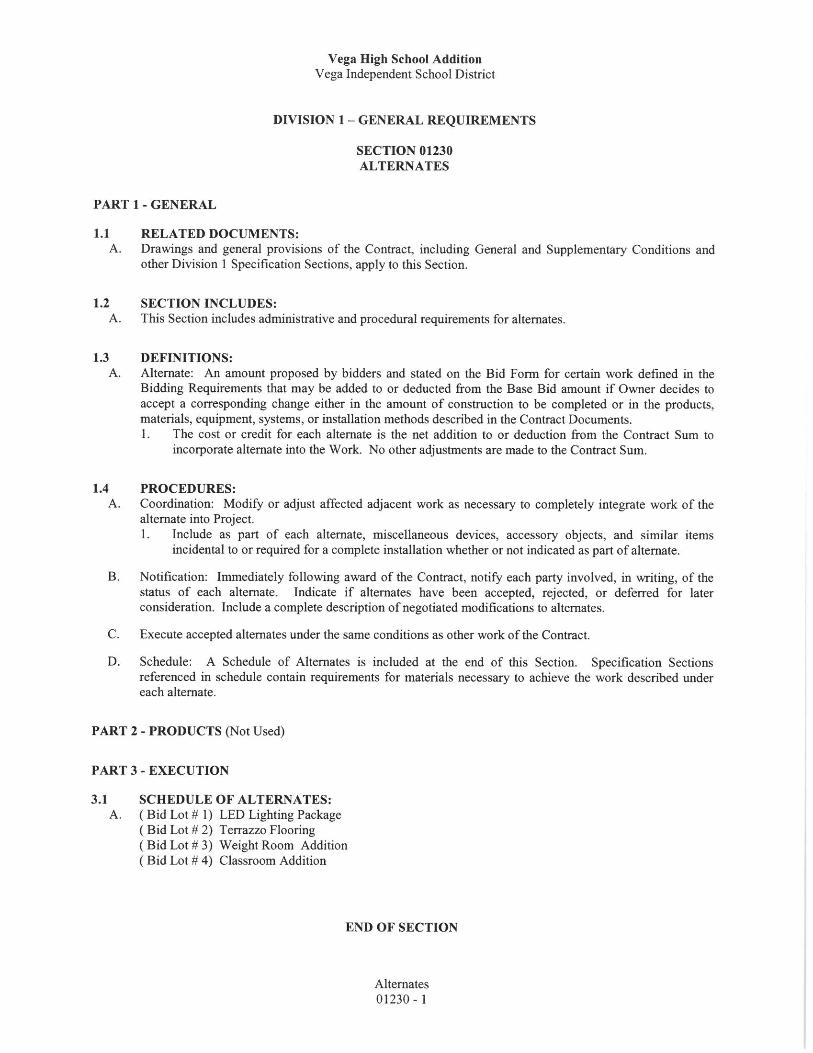
Addendum
Addendum No.: 003
Date: February 9, 2016
Project: Vega High School
Project No.: 14-0424
From: Brian Barnes Dekker/Perich/Sabatini 7601 Jefferson St. NE, Suite 100 Albuquerque, NM 87109
To: All Prospective Bidders and Plan Holders
This Addendum forms a part of the Bid Documents and modifies the Bid Documents issued by Dekker/Perich/Sabatini (D/P/S) and dated 5/5/2014. All other provisions of the Bid Documents shall remain unchanged. 1. DRAWINGS:
1.1. SD101 STRUCTURAL DEMOLITION PLANS 1.1.1. ADD KEYNOTE 13.
1.2. SB101B LOWER FOUNDATION PLAN – AREA B 1.2.1. Add note about lintels in basement. 1.2.2. Adjust walls per architectural revisions.
1.3. SB102A FOUNDATION PLAN – AREA A 1.3.1. Add miscellaneous callouts at masonry and concrete walls.
1.4. SB102B FOUNDATION PLAN – AREA B 1.4.1. Adjust opening in slab at stair, coordinate with architectural. 1.4.2. Add footing at gridline E/7. 1.4.3. Change studs from gridline F to H.
1.5. SB301 FOUNDATION SECTIONS 1.5.1. Modify section D4. 1.5.2. Add section C6.
1.6. SB302 FOUNDATION SECTIONS 1.6.1. CLARIFY D5 AND A3.
1.7. SB303 FOUNDATION SECTIONS 1.7.1. Clarify information in sections D5, D6, B6 and D2.
1.8. SB304 FOUNDATION SECTIONS 1.8.1. CLARIFY DETAIL A6 AND B6.
1.9. SF103A ROOF FRAMING PLANS – AREA A 1.9.1. Clarify joist bearing in A3.
1.10. SF103B ROOF FRAMING PLANS – AREA B 1.10.1. Adjust framing between gridlines 7 and 11/F and H. 1.10.2. Clarify elevator support framing. 1.10.3. Adjust framing sizes. 1.10.4. Clarify wall detailing along gridline B.
1.11. SB103C ROOF FRAMING PLANS – AREA C 1.11.1. Clarify keynote 13.
1.12. SF201 BRACED FRAME ELEVATIONS 1.12.1. ADJUST BRACE SIZE ON C1.
1.13. SF202 WALL ELEVATIONS 1.13.1. Clarify detailing for support of Wall along gridline A.
1.14. SF301 FRAMING SECTIONS 1.14.1. Remove all around weld symbol on E6. 1.14.2. Clarify section A5, A6, B5 and C4. 1.14.3. Add section A1.
1.15. SF303 FRAMING SECTIONS 1.15.1. Add sections A4 and A5.

Page 2 of 2
1.15.2. Clarify deck in E5. 1.16. SF401 ENLARGED PLANS
1.16.1. Adjust stair shown on C3 and A3. 1.17. SF501 FRAMING DETAILS
1.17.1. Add detail B1. 1.17.2. Modify detail B1.
1.18. SF502 FRAMING DETAILS 1.18.1. Clarify detail callouts in A5. 1.18.2. Clarify braced frame connection schedule on A3.
2. SPECIFICATIONS 2.1. 03 3000 CAST IN PLACE CONCRETE
2.1.1. Remove line 2.2B in its entirety. Attachments:
Drawings: SD101, SB101B, SB102A, SB102B, SB301, SB302 , SB303, SB304, SF103A, SF103B, SB103C,
SF201, SF202, SF301, SF303, SF401, SF501 , SF502 All other provisions of the Contract Documents shall remain unchanged. This addendum is hereby made a part of the Contract Documents to the same extent as those provisions contained in the original documents and all itemized listings thereof. End of Addendum

Page 1 of 1
Addendum
Addendum No.: 003 (Metal Building)
Date: February 9, 2016
Project: Vega High School
Project No.: 14-0424
From: Brian Barnes Dekker/Perich/Sabatini 7601 Jefferson St. NE, Suite 100 Albuquerque, NM 87109
To: All Prospective Bidders and Plan Holders
This Addendum forms a part of the Bid Documents and modifies the Bid Documents issued by Dekker/Perich/Sabatini (D/P/S) and dated 5/5/2014. All other provisions of the Bid Documents shall remain unchanged. 1. DRAWINGS:
1.1. S-501 FOUNDATION DETAILS 1.1.1. Clarify notes in D4 and D2. 1.1.2. Adjust lintel reinforcement in A4.
Attachments: Drawings S-501 All other provisions of the Contract Documents shall remain unchanged. This addendum is hereby made a part of the Contract Documents to the same extent as those provisions contained in the original documents and all itemized listings thereof. End of Addendum

Vega High School
Vega Independent School District
METAL BUILDING SYSTEMS 13 12 50 – 1
SECTION 13 12 50 - METAL BUILDING SYSTEMS
PART 1 - GENERAL
1.1 SUMMARY
A. This Section includes metal building systems that consist of integrated sets of mutually dependent
components including structural framing, roof panels, wall panels, soffit panels, and accessories.
B. See Division 3 Section "Cast-in-Place Concrete" for concrete foundations, slabs, and anchor-bolt
installation.
1.2 SYSTEM PERFORMANCE REQUIREMENTS
A. Structural Performance: Provide metal building systems capable of withstanding the effects of gravity
loads and the following loads and stresses within limits and under conditions indicated:
1. Engineer metal building systems according to procedures in MBMA's "Metal Building Systems
Manual."
2. Design Loads: As indicated on Drawings.
3. Design Loads: As required by ASCE 7, "Minimum Design Loads for Buildings and Other
Structures."
B. Seismic Performance: Design and engineer metal building systems capable of withstanding the effects of
earthquake motions determined according to ASCE 7, "Minimum Design Loads for Buildings and Other
Structures": Section 9, "Earthquake Loads."
C. Thermal Movements: Provide metal panel systems that allow for thermal movements resulting from the
following maximum change (range) in ambient and surface temperatures by preventing buckling, opening
of joints, overstressing of components, failure of joint sealants, failure of connections, and other
detrimental effects. Base engineering calculation on surface temperatures of materials due to both solar
heat gain and nighttime-sky heat loss.
D. Wind-Uplift Resistance: Provide metal roof panel assemblies that comply with UL 580 for Class 90.
1.3 SUBMITTALS
A. Product Data: For each type of metal building system component indicated.
B. Shop Drawings: Include plans, elevations, sections, details, and attachments to other work.
1. For installed products indicated to comply with design loads, include structural analysis data
signed and sealed by the qualified professional engineer responsible for their preparation.
2. Anchor-Bolt Plans: Submit anchor-bolt plans before foundation work begins. Include location,
diameter, and projection of anchor bolts required to attach metal building to foundation. Indicate
column reactions at each location.
3. Structural-Framing Drawings: Show complete fabrication of primary and secondary framing;
include provisions for openings. Indicate welds and bolted connections, distinguishing between
shop and field applications. Include transverse cross-sections.
4. Metal Roof and Wall Panel Layout Drawings: Show layouts of metal panels including methods of
support. Include details of edge conditions, joints, panel profiles, corners, anchorages, trim,

Vega High School
Vega Independent School District
METAL BUILDING SYSTEMS 13 12 50 – 2
flashings, closures, and special details. Distinguish between factory- and field-assembled work;
show locations of exposed fasteners.
C. Samples: For each type of building component and for each color and texture required.
D. Letter of Design Certification: Signed and sealed by a qualified professional engineer. Include the
following:
1. Name and location of Project.
2. Order number.
3. Name of manufacturer.
4. Name of Contractor.
5. Building dimensions including width, length, height, and roof slope.
6. Indicate compliance with AISC standards for hot-rolled steel and AISI standards for cold-rolled
steel, including edition dates of each standard.
7. Governing building code and year of edition.
8. Design loads and load combinations.
9. Building-use category.
10. AISC Certification for Category MB: Include statement that metal building system and
components were designed and produced in an AISC-Certified Facility by an AISC-Certified
Manufacturer.
E. Welding certificates.
F. Erector Certificate: Signed by manufacturer certifying that erector complies with requirements.
G. Manufacturer certificate.
H. Surveys: Show final elevations and locations of major members. Have surveyor who performed surveys
certify their accuracy.
1.4 QUALITY ASSURANCE
A. Erector Qualifications: An experienced erector who has specialized in erecting and installing work
similar in material, design, and extent to that indicated for this Project and who is acceptable to
manufacturer.
B. Manufacturer Qualifications: A qualified manufacturer and member of MBMA.
1. AISC Certification for Category MB: An AISC-Certified Manufacturer that designs and produces
metal building systems and components in an AISC-Certified Facility.
2. Engineering Responsibility: Preparation of Shop Drawings and comprehensive engineering
analysis by a qualified professional engineer.
C. Welding: Qualify procedures and personnel according to AWS D1.1, "Structural Welding Code--Steel,"
and AWS D1.3, "Structural Welding Code--Sheet Steel."
D. Structural Steel: Comply with AISC's "Specification for Structural Steel Buildings--Allowable Stress
Design, Plastic Design," or AISC's "Load and Resistance Factor Design Specification for Structural Steel
Buildings," for design requirements and allowable stresses.
E. Cold-Formed Steel: Comply with AISI's "Specification for the Design of Cold-Formed Steel Structural
Members," or AISI's "Load and Resistance Factor Design Specification for Steel Structural Members,"
for design requirements and allowable stresses.

Vega High School
Vega Independent School District
METAL BUILDING SYSTEMS 13 12 50 – 3
F. Pre-Erection Conference: Conduct conference at Project site to comply with requirements in Division 1
Section "Project Management and Coordination." Review methods and procedures related to metal
building systems including, but not limited to, the following:
1. Inspect and discuss condition of foundations and other preparatory work performed by other
trades.
2. Review structural load limitations.
3. Review required testing, inspecting, and certifying procedures.
1.5 DELIVERY, STORAGE, AND HANDLING
A. Stack metal panels horizontally on platforms or pallets, covered with suitable weathertight and ventilated
covering. Store metal panels to ensure dryness and with positive slope for drainage of water. Do not
store metal panels in contact with other materials that might cause staining, denting, or other surface
damage.
1.6 PROJECT CONDITIONS
A. Established Dimensions for Foundations: Comply with established dimensions on approved anchor-bolt
plans, establishing foundation dimensions and proceeding with fabricating structural framing without
field measurements. Coordinate anchor-bolt installation to ensure that actual anchorage dimensions
correspond to established dimensions.
1.7 COORDINATION
A. Coordinate size and location of concrete foundations and casting of anchor-bolt inserts into foundation
walls and footings. Concrete, reinforcement, and formwork requirements are specified in Division 3
Section "Cast-in-Place Concrete."
B. Coordinate installation of equipment supports and roof penetrations, which are specified in Division 7
Section "Roof Accessories."
1.8 WARRANTY
A. Special Warranty on Metal Panel Finishes: Manufacturer's standard form in which manufacturer agrees
to repair finish or replace metal panels that show evidence of deterioration of factory-applied finishes
within specified warranty period.
1. Siliconized Polyester Finish: Deterioration includes, but is not limited to, the following:
a. Color fading more than 15 Hunter units when tested according to ASTM D 2244.
b. Chalking in excess of a No. 2 rating when tested according to ASTM D 4214.
c. Cracking, checking, peeling, or failure of paint to adhere to bare metal.
2. Fluoropolymer Finish: Deterioration includes, but is not limited to, the following:
a. Color fading more than 5 Hunter units when tested according to ASTM D 2244.
b. Chalking in excess of a No. 8 rating when tested according to ASTM D 4214.
c. Cracking, checking, peeling, or failure of paint to adhere to bare metal.
3. Finish Warranty Period: 20 years from date of Substantial Completion.

Vega High School
Vega Independent School District
METAL BUILDING SYSTEMS 13 12 50 – 4
PART 2 - PRODUCTS
2.1 MANUFACTURERS
A. Available Manufacturers: Subject to compliance with requirements, manufacturers offering products that
may be incorporated into the Work include, but are not limited to, the following:
B. Manufacturers: Subject to compliance with requirements, provide products by one of the following:
1. Alliance Steel, Inc.
2. American Buildings Company.
3. American Steel Building Company, Inc.; Division of NCI Building Systems, LLP.
4. Behlen Mfg. Co.
5. Butler Manufacturing Company.
6. Ceco Building Systems; Division of Robertson-Ceco Corporation.
7. Crown Metal Buildings, Inc.
8. Garco Building Systems.
9. Gulf States Manufacturers, Inc.
10. Mesco Metal Buildings; Division of NCI Building Systems, LLP.
11. Metallic Metal Building Company; Division of NCI Building Systems, LLP.
12. Package Industries, Inc.
13. Southern Structures, Inc.
14. Spirco Manufacturing; Division of Metal Building Products, Inc.
15. Star Building Systems; Division of Robertson-Ceco Corporation.
16. Steelox Systems Inc.
17. United Structures of America, Inc.
18. VP Buildings, Inc.; a United Dominion Company.
2.2 STRUCTURAL-FRAMING MATERIALS
A. Refer to Sheet S101, Structural General Notes and Specifications.
2.3 MATERIALS FOR FIELD-ASSEMBLED METAL PANELS
A. Metallic-Coated Steel Sheet Prepainted with Coil Coating: Steel sheet metallic coated by the hot-dip
process and prepainted by the coil-coating process to comply with ASTM A 755/A 755M.
1. Zinc-Coated (Galvanized) Steel Sheet: ASTM A 653/A 653M, Structural Steel (SS), Grades 33
through 80, with G90 coating designation.
2. Aluminum-Zinc Alloy-Coated Steel Sheet: ASTM A 792/A 792M, Structural Steel (SS),
Grade 50 or 80; with Class AZ50 coating designation.
3. Surface: Smooth, flat finish.
4. Exposed Finishes: Apply the following coil coating, as specified or indicated on Drawings:
a. Acrylic-Enamel Coating: Epoxy primer and acrylic-enamel topcoat; with a dry film
thickness of not less than 0.2 mil for primer and 0.8 mil for topcoat.
b. Siliconized-Polyester Coating: Epoxy primer and silicone-modified, polyester-enamel
topcoat; with a dry film thickness of not less than 0.2 mil for primer and 0.8 mil for
topcoat.
c. High-Performance Organic Finish (2-Coat Fluoropolymer): AA-C12C40R1x (Chemical
Finish: cleaned with inhibited chemicals; Chemical Finish: conversion coating; Organic
Coating: manufacturer's standard 2-coat, thermocured system consisting of specially

Vega High School
Vega Independent School District
METAL BUILDING SYSTEMS 13 12 50 – 5
formulated inhibitive primer and fluoropolymer color topcoat containing not less than 70
percent polyvinylidene fluoride resin by weight). Prepare, pretreat, and apply coating to
exposed metal surfaces to comply with AAMA 2604 and with coating and resin
manufacturers' written instructions, except as modified below:
1) Humidity Resistance: 1000 hours.
2) Salt-Spray Resistance: 1000 hours.
d. Concealed Finish: Apply pretreatment and manufacturer's standard white or light-colored
backer finish, consisting of prime coat and wash coat with a total minimum dry film
thickness of 0.5 mil.
2.4 DOOR AND FRAME MATERIALS
A. Cold-Rolled Steel Sheet: ASTM A 1008/A 1008M, Commercial Steel (CS), Type B, suitable for exposed
applications.
B. Hot-Rolled Steel Sheet: ASTM A 1011/A 1011M, Commercial Steel (CS), Type B; free of scale, pitting,
or surface defects; pickled and oiled.
C. Metallic-Coated Steel Sheet: ASTM A 653/A 653M, Commercial Steel (CS), Type B; with G60 zinc
(galvanized) or A60 zinc-iron-alloy (galvannealed) coating designation.
2.5 MISCELLANEOUS MATERIALS
A. Fasteners: Self-tapping screws, bolts, nuts, self-locking rivets and bolts, end-welded studs, and other
suitable fasteners designed to withstand design loads. Provide fasteners with heads matching color of
materials being fastened by means of plastic caps or factory-applied coating.
1. Fasteners for Metal Roof Panels: Self-drilling or self-tapping, zinc-plated, hex-head carbon-steel
screws, with a stainless-steel cap or zinc-aluminum-alloy head and EPDM or neoprene sealing
washer.
2. Fasteners for Metal Wall Panels: Self-drilling or self-tapping, zinc-plated, hex-head carbon-steel
screws, with nylon or polypropylene washer.
3. Fasteners for Metal Roof and Wall Panels: Self-drilling Type 410 stainless-steel or self-tapping
Type 304 stainless-steel or zinc-alloy-steel hex washer head, with EPDM or PVC washer under
heads of fasteners bearing on weather side of metal panels.
B. Bituminous Coating: Cold-applied asphalt mastic, SSPC-Paint 12, compounded for 15-mil dry film
thickness per coat. Provide inert-type noncorrosive compound free of asbestos fibers, sulfur components,
and other deleterious impurities.
C. Nonmetallic, Shrinkage-Resistant Grout: ASTM C 1107, factory-packaged, nonmetallic aggregate grout,
noncorrosive, nonstaining, mixed with water to consistency suitable for application and a 30-minute
working time.
D. Metal Panel Sealants:
1. Sealant Tape: Pressure-sensitive, 100 percent solids, gray polyisobutylene compound sealant tape
with release-paper backing.
2. Joint Sealant: ASTM C 920; one-part elastomeric polyurethane, polysulfide, or silicone-rubber
sealant.
3. VOC content

Vega High School
Vega Independent School District
METAL BUILDING SYSTEMS 13 12 50 – 6
2.6 FABRICATION, GENERAL
A. Tolerances: Comply with MBMA's "Metal Building Systems Manual": Chapter IV, Section 9,
"Fabrication and Erection Tolerances."
B. Metal Panels: Provide panel profile, including major ribs and intermediate stiffening ribs, if any, for full
length of metal panel.
2.7 STRUCTURAL FRAMING
A. General:
1. Primary Framing: Shop fabricate framing components to indicated size and section with
baseplates, bearing plates, stiffeners, and other items required for erection welded into place. Cut,
form, punch, drill, and weld framing for bolted field assembly.
a. Make shop connections by welding or by using high-strength bolts.
b. Join flanges to webs of built-up members by a continuous submerged arc-welding process.
c. Brace compression flange of primary framing with steel angles or cold-formed structural
tubing between frame web and purlin or girt web, so flange compressive strength is within
allowable limits for any combination of loadings.
d. Shop Priming: Prepare surfaces for shop priming according to SSPC-SP 2. Shop prime
primary structural members with specified primer after fabrication.
2. Secondary Framing: Shop fabricate framing components to indicated size and section by roll-
forming or break-forming, with baseplates, bearing plates, stiffeners, and other plates required for
erection welded into place. Cut, form, punch, drill, and weld secondary framing for bolted field
connections to primary framing.
a. Shop Priming: Prepare uncoated surfaces for shop priming according to SSPC-SP 2. Shop
prime uncoated secondary structural members with specified primer after fabrication.
B. Primary Framing: Manufacturer's standard structural primary framing system, designed to withstand
required loads and specified requirements. Primary framing includes transverse and lean-to frames;
rafter, rake, and canopy beams; sidewall, intermediate, end-wall, and corner columns; and wind bracing.
Provide frames with attachment plates, bearing plates, and splice members. Factory drill for field-bolted
assembly. Provide frame span and spacing indicated.
1. Rigid Clear-Span Frames: I-shaped frame sections fabricated from shop-welded, built-up steel
plates or structural-steel shapes. Interior columns are not permitted.
2. Rigid Modular Frames: I-shaped frame sections fabricated from shop-welded, built-up steel plates
or structural-steel shapes. Provide interior columns fabricated from round steel pipe or tube, or
shop-welded, built-up steel plates.
3. Frame Configuration: Single gable.
4. Exterior Column Type: Tapered.
5. Rafter Type: Tapered.
C. End-Wall Framing: Manufacturer's standard primary end-wall framing fabricated for field-bolted
assembly to comply with the following:
1. End-Wall and Corner Columns: I-shaped sections fabricated from structural-steel shapes; shop-
welded, built-up steel plates; or C-shaped, cold-formed, structural-steel sheet; with minimum
thickness of 0.0598 inch.
Vega High School
Vega Independent School District
METAL BUILDING SYSTEMS 13 12 50 – 7
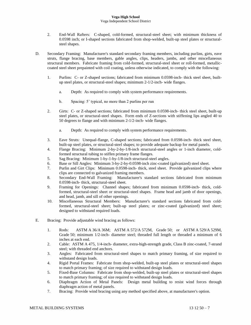
2. End-Wall Rafters: C-shaped, cold-formed, structural-steel sheet; with minimum thickness of
0.0598 inch; or I-shaped sections fabricated from shop-welded, built-up steel plates or structural-
steel shapes.
D. Secondary Framing: Manufacturer's standard secondary framing members, including purlins, girts, eave
struts, flange bracing, base members, gable angles, clips, headers, jambs, and other miscellaneous
structural members. Fabricate framing from cold-formed, structural-steel sheet or roll-formed, metallic-
coated steel sheet prepainted with coil coating, unless otherwise indicated, to comply with the following:
1. Purlins: C- or Z-shaped sections; fabricated from minimum 0.0598-inch- thick steel sheet, built-
up steel plates, or structural-steel shapes; minimum 2-1/2-inch- wide flanges.
a. Depth: As required to comply with system performance requirements.
b. Spacing: 5’ typical, no more than 2 purlins per run
2. Girts: C- or Z-shaped sections; fabricated from minimum 0.0598-inch- thick steel sheet, built-up
steel plates, or structural-steel shapes. Form ends of Z-sections with stiffening lips angled 40 to
50 degrees to flange and with minimum 2-1/2-inch- wide flanges.
a. Depth: As required to comply with system performance requirements.
3. Eave Struts: Unequal-flange, C-shaped sections; fabricated from 0.0598-inch- thick steel sheet,
built-up steel plates, or structural-steel shapes; to provide adequate backup for metal panels.
4. Flange Bracing: Minimum 2-by-2-by-1/8-inch structural-steel angles or 1-inch diameter, cold-
formed structural tubing to stiffen primary frame flanges.
5. Sag Bracing: Minimum 1-by-1-by-1/8-inch structural-steel angles.
6. Base or Sill Angles: Minimum 3-by-2-by-0.0598-inch zinc-coated (galvanized) steel sheet.
7. Purlin and Girt Clips: Minimum 0.0598-inch- thick, steel sheet. Provide galvanized clips where
clips are connected to galvanized framing members.
8. Secondary End-Wall Framing: Manufacturer's standard sections fabricated from minimum
0.0598-inch- thick, structural-steel sheet.
9. Framing for Openings: Channel shapes; fabricated from minimum 0.0598-inch- thick, cold-
formed, structural-steel sheet or structural-steel shapes. Frame head and jamb of door openings,
and head, jamb, and sill of other openings.
10. Miscellaneous Structural Members: Manufacturer's standard sections fabricated from cold-
formed, structural-steel sheet; built-up steel plates; or zinc-coated (galvanized) steel sheet;
designed to withstand required loads.
E. Bracing: Provide adjustable wind bracing as follows:
1. Rods: ASTM A 36/A 36M; ASTM A 572/A 572M, Grade 50; or ASTM A 529/A 529M,
Grade 50; minimum 1/2-inch- diameter steel; threaded full length or threaded a minimum of 6
inches at each end.
2. Cable: ASTM A 475, 1/4-inch- diameter, extra-high-strength grade, Class B zinc-coated, 7-strand
steel; with threaded end anchors.
3. Angles: Fabricated from structural-steel shapes to match primary framing, of size required to
withstand design loads.
4. Rigid Portal Frames: Fabricate from shop-welded, built-up steel plates or structural-steel shapes
to match primary framing; of size required to withstand design loads.
5. Fixed-Base Columns: Fabricate from shop-welded, built-up steel plates or structural-steel shapes
to match primary framing; of size required to withstand design loads.
6. Diaphragm Action of Metal Panels: Design metal building to resist wind forces through
diaphragm action of metal panels.
7. Bracing: Provide wind bracing using any method specified above, at manufacturer's option.

Vega High School
Vega Independent School District
METAL BUILDING SYSTEMS 13 12 50 – 8
F. Bolts: Provide plain finish bolts for structural-framing components that are primed or finish painted.
Provide hot-dipped galvanized bolts for structural-framing components that are galvanized.
G. Factory-Primed Finish: Apply specified primer immediately after cleaning and pretreating.
1. Prime primary, secondary, and end-wall structural-framing members to a minimum dry film
thickness of 1 mil.
a. Prime secondary steel framing formed from uncoated steel sheet to a minimum dry film
thickness of 0.5 mil on each side.
2. Prime galvanized members with specified primer, after phosphoric acid pretreatment.
2.8 METAL ROOF PANELS
A. Vertical-Rib, Standing-Seam Metal Roof Panels: Formed with vertical ribs at panel edges and
intermediate stiffening ribs symmetrically spaced between ribs; designed for sequential installation by
mechanically attaching panels to supports using concealed clips located under one side of panels and
engaging opposite edge of adjacent panels.
1. Material: Zinc-coated (galvanized) steel sheet, 0.0209 inch thick.
a. Exterior Finish: Fluoropolymer.
b. Color: As selected by Architect from manufacturer's full range.
2. Clips: Manufacturer's standard, floating type to accommodate thermal movement; fabricated from
zinc-coated (galvanized) steel, aluminum-zinc alloy-coated steel, or stainless-steel sheet.
3. Joint Type: Panels snapped together.
4. Joint Type: Mechanically seamed, folded as standard with manufacturer.
5. Panel Coverage: 16 inches.
6. Panel Height: 2 inches.
2.9 FIELD-ASSEMBLED METAL WALL PANELS
A. Tapered-Rib-Profile, Exposed-Fastener Metal Wall Panels: Formed with raised, trapezoidal major ribs
and intermediate stiffening ribs symmetrically spaced between major ribs; designed to be field assembled
by lapping side edges of adjacent panels and mechanically attaching panels to supports using exposed
fasteners in side laps.
1. Material: Zinc-coated (galvanized) steel sheet, 0.0209 inch thick.
a. Exterior Finish: Fluoropolymer.
b. Color: As selected by Architect from manufacturer's full range.
2. Major-Rib Spacing: 12 inches o.c.
3. Panel Coverage: 36 inches.
4. Panel Height: 1.125 inches.
2.10 METAL SOFFIT PANELS
A. General: Provide factory-formed metal soffit panels designed to be field assembled by lapping and
interconnecting side edges of adjacent panels and mechanically attaching through panel to supports using

Vega High School
Vega Independent School District
METAL BUILDING SYSTEMS 13 12 50 – 9
concealed fasteners and factory-applied sealant in side laps. Include accessories required for weathertight
installation.
B. Metal Soffit Panels: Match profile and material of metal wall panels.
1. Finish: As selected by Architect from manufacturer's full range.
C. Concealed-Fastener Metal Soffit Panels: Formed with vertical panel edges and a single wide recess,
centered between panel edges; with flush joint between panels; with 1-inch- wide flange for attaching
interior finish; designed to be field assembled by lapping and interconnecting side edges of adjacent
panels and mechanically attaching through panel to supports using concealed fasteners and factory-
applied sealant in side laps.
1. Material: Zinc-coated (galvanized) steel sheet, 0.0209 inch thick.
a. Exterior Finish: Fluoropolymer.
b. Color: As selected by Architect from manufacturer's full range.
2. Panel Coverage: 12 inches.
3. Panel Height: 1 inch.
2.11 ACCESSORIES
A. General: Provide accessories as standard with metal building system manufacturer and as specified.
Fabricate and finish accessories at the factory to greatest extent possible, by manufacturer's standard
procedures and processes. Comply with indicated profiles and with dimensional and structural
requirements.
B. Roof Panel Accessories: Provide components required for a complete metal roof panel assembly
including copings, fasciae, corner units, ridge closures, clips, sealants, gaskets, fillers, closure strips, and
similar items. Match material and finish of metal roof panels, unless otherwise indicated.
1. Closures: Provide closures at eaves and ridges, fabricated of same material as metal roof panels.
2. Clips: Manufacturer's standard, formed from steel sheet, designed to withstand negative-load
requirements.
3. Cleats: Manufacturer's standard, mechanically seamed cleats formed from steel sheet.
4. Backing Plates: Provide metal backing plates at panel end splices, fabricated from material
recommended by manufacturer.
5. Closure Strips: Closed-cell, expanded, cellular, rubber or crosslinked, polyolefin-foam or closed-
cell laminated polyethylene; minimum 1-inch- thick, flexible closure strips; cut or premolded to
match metal roof panel profile. Provide closure strips where indicated or necessary to ensure
weathertight construction.
C. Wall Panel Accessories: Provide components required for a complete metal wall panel assembly
including copings, fasciae, mullions, sills, corner units, clips, sealants, gaskets, fillers, closure strips, and
similar items. Match material and finish of metal wall panels, unless otherwise indicated.
1. Closures: Provide closures at eaves and rakes, fabricated of same material as metal wall panels.
2. Closure Strips: Closed-cell, expanded, cellular, rubber or crosslinked, polyolefin-foam or closed-
cell laminated polyethylene; minimum 1-inch- thick, flexible closure strips; cut or premolded to
match metal wall panel profile. Provide closure strips where indicated or necessary to ensure
weathertight construction.
D. Flashing and Trim: Formed from minimum 0.0159-inch- thick, metallic-coated steel sheet or aluminum-
zinc alloy-coated steel sheet prepainted with coil coating; finished to match adjacent metal panels.

Vega High School
Vega Independent School District
METAL BUILDING SYSTEMS 13 12 50 – 10
1. Opening Trim: Minimum 0.0269-inch- thick, metallic-coated steel sheet or aluminum-zinc alloy-
coated steel sheet prepainted with coil coating. Trim head and jamb of door openings, and head,
jamb, and sill of other openings.
E. Gutters: Formed from minimum 0.0159-inch- thick, metallic-coated steel sheet or aluminum-zinc alloy-
coated steel sheet prepainted with coil coating; finished to match roof fascia and rake trim. Match profile
of gable trim, complete with end pieces, outlet tubes, and other special pieces as required. Fabricate in
minimum 96-inch- long sections, sized according to SMACNA's "Architectural Sheet Metal Manual."
1. Gutter Supports: Fabricated from same material and finish as gutters; spaced 36 inches o.c.
F. Downspouts: Formed from 0.0159-inch- thick, zinc-coated (galvanized) steel sheet or aluminum-zinc
alloy-coated steel sheet prepainted with coil coating; finished to match metal wall panels. Fabricate in
minimum 10-foot- long sections, complete with formed elbows and offsets.
1. Mounting Straps: Fabricated from same material and finish as gutters; spaced 10 feet o.c.
G. Roof Ventilators: Gravity type, complete with hardware, flashing, closures, and fittings.
1. Continuous or Sectional-Ridge Type: Factory-engineered and -fabricated, continuous unit;
fabricated from minimum 0.0159-inch- thick, metallic-coated steel sheet or aluminum-zinc alloy-
coated steel sheet prepainted with coil coating; finished to match metal roof panels. Fabricated in
minimum 10-foot- long sections. Provide throat size and total length indicated, complete with
side baffles, ventilator assembly, end caps, splice plates, and reinforcing diaphragms.
a. Bird Screening: Galvanized steel, 1/2-inch- square mesh, 0.041-inch wire, or aluminum,
1/2-inch- square mesh, 0.063-inch wire.
b. Dampers: Manually operated, spring-loaded, vertically rising type; with chain and worm
gear operator.
c. Throat Size: 12 inches.
H. Pipe Flashing: Premolded, EPDM pipe collar with flexible aluminum ring bonded to base.
2.12 SOURCE QUALITY CONTROL
A. Testing Agency: Owner will engage a qualified testing and inspecting agency to perform the following
tests and inspections and to submit reports.
B. Special Inspector: Owner will engage a qualified special inspector to perform the following tests and
inspections and to submit reports. Special Inspector will verify that manufacturer maintains detailed
fabrication and quality-control procedures and will review the completeness and adequacy of those
procedures to perform the Work.
1. Special inspections will not be required if fabrication is performed by a manufacturer registered
and approved by authorities having jurisdiction to perform such Work without special inspection.
a. After fabrication, submit certificate of compliance with copy to authorities having
jurisdiction certifying that Work was performed according to Contract requirements.
C. Tests and Inspections:
1. Bolted Connections: Shop-bolted connections shall be tested and inspected according to RCSC's
"Specification for Structural Joints Using ASTM A 325 or A 490 Bolts."

Vega High School
Vega Independent School District
METAL BUILDING SYSTEMS 13 12 50 – 11
2. Welded Connections: In addition to visual inspection, shop-welded connections shall be tested
and inspected according to AWS D1.1.
PART 3 - EXECUTION
3.1 ERECTION
A. Before erection proceeds, survey elevations and locations of concrete- and masonry-bearing surfaces and
locations of anchor rods, bearing plates, and other embedments to receive structural framing, with Erector
present, for compliance with requirements and metal building system manufacturer's tolerances.
B. Provide temporary shores, guys, braces, and other supports during erection to keep structural framing
secure, plumb, and in alignment against temporary construction loads and loads equal in intensity to
design loads. Remove temporary supports when permanent structural framing, connections, and bracing
are in place, unless otherwise indicated.
C. Erect metal building system according to manufacturer's written erection instructions and erection
drawings.
D. Do not field cut, drill, or alter structural members without written approval from metal building system
manufacturer's professional engineer.
E. Set structural framing accurately in locations and to elevations indicated and according to AISC
specifications referenced in this Section. Maintain structural stability of frame during erection.
F. Base and Bearing Plates: Clean concrete- and masonry-bearing surfaces of bond-reducing materials, and
roughen surfaces prior to setting plates. Clean bottom surface of plates.
1. Set plates for structural members on wedges, shims, or setting nuts as required.
2. Tighten anchor rods after supported members have been positioned and plumbed. Do not remove
wedges or shims but, if protruding, cut off flush with edge of plate before packing with grout.
3. Promptly pack grout solidly between bearing surfaces and plates so no voids remain. Neatly
finish exposed surfaces; protect grout and allow to cure. Comply with manufacturer's written
installation instructions for shrinkage-resistant grouts.
G. Align and adjust structural framing before permanently fastening. Before assembly, clean bearing
surfaces and other surfaces that will be in permanent contact with framing. Perform necessary
adjustments to compensate for discrepancies in elevations and alignment. Level and plumb individual
members of structure.
H. Primary Framing and End Walls: Erect framing true to line, level, plumb, rigid, and secure. Level
baseplates to a true even plane with full bearing to supporting structures, set with double-nutted anchor
bolts. Use grout to obtain uniform bearing and to maintain a level base-line elevation. Moist cure grout
for not less than seven days after placement.
1. Make field connections using high-strength bolts installed according to RCSC's "Specification for
Structural Joints Using ASTM A 325 or A 490 Bolts" for type of bolt and snug-tightened or
pretensioned joints.
I. Secondary Framing: Erect framing true to line, level, plumb, rigid, and secure. Fasten secondary framing
to primary framing using clips with field connections using non-high-strength bolts.
1. Provide rake or gable purlins with tight-fitting closure channels and fasciae.
Vega High School
Vega Independent School District
METAL BUILDING SYSTEMS 13 12 50 – 12
2. Locate and space wall girts to suit openings such as doors and windows.
3. Provide supplemental framing at entire perimeter of openings, including doors, windows, louvers,
ventilators, and other penetrations of roof and walls.
J. Bracing: Install bracing in roof and sidewalls where indicated on erection drawings.
1. Tighten rod and cable bracing to avoid sag.
2. Locate interior end-bay bracing only where indicated.
K. Framing for Openings: Provide shapes of proper design and size to reinforce openings and to carry loads
and vibrations imposed, including equipment furnished under mechanical and electrical work. Securely
attach to structural framing.
L. Erection Tolerances: Maintain erection tolerances of structural framing within AISC's "Code of Standard
Practice for Steel Buildings and Bridges."
3.2 METAL PANEL INSTALLATION, GENERAL
A. General: Anchor metal panels and other components of the Work securely in place, with provisions for
thermal and structural movement.
1. Field cut metal panels as required for doors, windows, and other openings. Cut openings as small
as possible, neatly to size required, and without damage to adjacent metal panel finishes. Field
cutting of metal panels by torch is not permitted unless approved in writing by manufacturer.
2. Install metal panels perpendicular to structural supports, unless otherwise indicated.
3. Flash and seal metal panels with weather closures at perimeter of openings and similar elements.
Fasten with self-tapping screws.
4. Locate metal panel splices over, but not attached to, structural supports with end laps in alignment.
Stagger panel splices and end laps to avoid a four-panel lap splice condition.
5. Lap metal flashing over metal panels to allow moisture to run over and off the material.
B. Lap-Seam Metal Panels: Install screw fasteners with power tools having controlled torque adjusted to
compress neoprene washer tightly without damage to washer, screw threads, or metal panels. Install
screws in predrilled holes. Arrange and nest side-lap joints so prevailing winds blow over, not into,
lapped joints. Lap ribbed or fluted sheets one full rib corrugation.
C. Metal Protection: Where dissimilar metals will contact each other or corrosive substrates, protect against
galvanic action by painting contact surfaces with bituminous coating, by applying rubberized-asphalt
underlayment to each contact surface, or by other permanent separation as recommended by metal roof
panel manufacturer.
D. Joint Sealers: Install gaskets, joint fillers, and sealants where indicated and where required for
weatherproof performance of metal panel assemblies. Provide types of gaskets, fillers, and sealants
indicated or, if not indicated, types recommended by metal panel manufacturer.
3.3 METAL ROOF PANEL INSTALLATION
A. General: Provide metal roof panels of full length from eave to ridge, unless otherwise indicated or
restricted by shipping limitations. Install ridge caps as metal roof panel work proceeds.
B. Field-Assembled, Standing-Seam Metal Roof Panels: Fasten metal roof panels to supports with
concealed clips at each standing-seam joint at location, spacing, and with fasteners recommended by
manufacturer.

Vega High School
Vega Independent School District
METAL BUILDING SYSTEMS 13 12 50 – 13
1. Install clips to supports with self-tapping fasteners.
2. Snap Joint: Nest standing seams and fasten together by interlocking and completely engaging
factory-applied sealant.
3. Seamed Joint: Crimp standing seams with manufacturer-approved motorized seamer tool so clip,
metal roof panel, and factory-applied sealant are completely engaged.
4. Rigidly fasten eave end of metal roof panels and allow ridge end free movement due to thermal
expansion and contraction. Predrill panels for fasteners.
5. Provide metal closures at peaks, rake edges, rake walls, and each side of ridge caps.
C. Field-Assembled, Lap-Seam Metal Roof Panels: Fasten metal roof panels to supports with exposed
fasteners at each lapped joint at location and spacing recommended by manufacturer.
1. Provide sealant tape at lapped joints of metal roof panels and between panels and protruding
equipment, vents, and accessories.
2. Apply a continuous ribbon of sealant tape to weather-side surface of fastenings on end laps and on
side laps of nesting-type metal panels; on side laps of ribbed or fluted metal panels; and elsewhere
as needed to make metal panels weatherproof to driving rains.
3. At metal panel splices, nest panels with minimum 6-inch end lap, sealed with butyl-rubber sealant
and fastened together by interlocking clamping plates.
D. Metal Fascia Panels: Align bottom of metal panels and fasten with blind rivets, bolts, or self-tapping
screws. Flash and seal metal panels with weather closures where fasciae meet soffits, along lower panel
edges, and at perimeter of all openings.
3.4 METAL WALL PANEL INSTALLATION
A. General: Install metal wall panels in orientation, sizes, and locations indicated on Drawings. Install
panels perpendicular to girts, extending full height of building, unless otherwise indicated. Anchor metal
wall panels and other components of the Work securely in place, with provisions for thermal and
structural movement.
1. When two rows of metal panels are required, lap panels 4 inches minimum.
2. When building height requires two rows of metal panels at gable ends, align lap of gable panels
over metal wall panels at eave height.
3. Rigidly fasten base end of metal wall panels and allow eave end free movement due to thermal
expansion and contraction. Predrill panels.
4. Flash and seal metal wall panels with weather closures at eaves, rakes, and at perimeter of all
openings. Fasten with self-tapping screws.
5. Install screw fasteners in predrilled holes.
6. Apply elastomeric sealant continuously between metal base channel (sill angle) and concrete, and
elsewhere as indicated, or if not indicated, as necessary for waterproofing.
7. Align bottom of metal wall panels and fasten with blind rivets, bolts, or self-tapping screws.
8. Provide weatherproof escutcheons for pipe and conduit penetrating exterior walls.
B. Field-Assembled, Metal Wall Panels: Install metal wall panels on exterior side of girts. Attach metal
wall panels to supports with fasteners as recommended by manufacturer.
3.5 THERMAL INSULATION INSTALLATION FOR FIELD-ASSEMBLED METAL PANELS
A. General: Install insulation concurrently with metal wall panel installation, in thickness indicated to cover
entire wall, according to manufacturer's written instructions.

Vega High School
Vega Independent School District
METAL BUILDING SYSTEMS 13 12 50 – 14
1. Set vapor-retarder-faced units with vapor retarder to warm side of construction, unless otherwise
indicated. Do not obstruct ventilation spaces, except for firestopping.
2. Tape joints and ruptures in vapor retarder, and seal each continuous area of insulation to
surrounding construction to ensure airtight installation.
3. Install factory-laminated, vapor-retarder-faced blankets straight and true in one-piece lengths with
both sets of facing tabs sealed to provide a complete vapor retarder.
4. Install blankets straight and true in one-piece lengths. Install vapor retarder over insulation with
both sets of facing tabs sealed to provide a complete vapor retarder.
5. Protect all exposed insulation with “chicken-wire”.
B. Blanket Roof Insulation: Comply with the following installation method:
1. Over-Purlin-with-Spacer-Block Installation: Extend insulation and vapor retarder over and
perpendicular to top flange of secondary framing members. Install layer of filler insulation over
first layer to fill space formed by metal roof panel standoffs. Hold in place by panels fastened to
standoffs. Chicken-wire can also be used.
C. Blanket Wall Insulation: Extend insulation and vapor retarder over and perpendicular to top flange of
secondary framing members. Hold in place by metal wall panels fastened to secondary framing.
1. Retainer Strips: Install retainer strips at each longitudinal insulation joint, straight and taut,
nesting with secondary framing to hold insulation in place. Chicken-wire can also be used.
3.6 ACCESSORY INSTALLATION
A. General: Install accessories with positive anchorage to building and weathertight mounting, and provide
for thermal expansion. Coordinate installation with flashings and other components.
1. Install components required for a complete metal roof panel assembly including trim, copings,
ridge closures, seam covers, flashings, sealants, gaskets, fillers, closure strips, and similar items.
2. Install components for a complete metal wall panel assembly including trim, copings, corners,
seam covers, flashings, sealants, gaskets, fillers, closure strips, and similar items.
B. Flashing and Trim: Comply with performance requirements, manufacturer's written installation
instructions, and SMACNA's "Architectural Sheet Metal Manual." Provide concealed fasteners where
possible, and set units true to line and level as indicated. Install work with laps, joints, and seams that
will be permanently watertight and weather resistant.
1. Expansion Provisions: Provide for thermal expansion of exposed flashing and trim. Space
movement joints at a maximum of 10 feet with no joints allowed within 24 inches of corner or
intersection.
C. Gutters: Join sections with riveted and soldered or lapped and sealed joints. Attach gutters to eave with
gutter hangers spaced not more than 4 feet o.c. using manufacturer's standard fasteners. Provide end
closures and seal watertight with sealant. Provide for thermal expansion.
D. Downspouts: Join sections with 1-1/2-inch telescoping joints. Provide fasteners designed to hold
downspouts securely 1 inch away from walls; locate fasteners at top and bottom and at approximately 60
inches o.c. in between.
1. Provide elbows at base of downspouts to direct water away from building.
2. Tie downspouts to underground drainage system indicated.

Vega High School
Vega Independent School District
METAL BUILDING SYSTEMS 13 12 50 – 15
E. Circular Roof Ventilators: Set ventilators complete with necessary hardware, anchors, dampers, weather
guards, rain caps, and equipment supports. Mount ventilators on flat level base. Install preformed filler
strips at base to seal ventilator to metal roof panels.
F. Continuous Roof Ventilators: Set ventilators complete with necessary hardware, anchors, dampers,
weather guards, rain caps, and equipment supports. Join sections with splice plates and end-cap skirt
assemblies where required to achieve indicated length. Install preformed filler strips at base to seal
ventilator to metal roof panels.
G. Roof Curbs: Install curbs at locations indicated on Drawings. Install flashing around bases where they
meet metal roof panels.
H. Pipe Flashing: Form flashing around pipe penetration and metal roof panels. Fasten and seal to panel as
recommended by manufacturer.
I. Doors: After completing installation, test and adjust doors to operate easily, free of warp, twist, or
distortion.
J. Windows: Adjust operating sashes and ventilators, screens, hardware, and accessories for a tight fit at
contact points and weather stripping for smooth operation and weathertight closure. Lubricate hardware
and moving parts.
K. Roof Ventilators: After completing installation, including work by other trades, lubricate, test, and adjust
units to operate easily, free of warp, twist, or distortion as needed to provide fully functioning units.
3.7 FIELD QUALITY CONTROL
A. Testing Agency: Owner will engage a qualified testing and inspecting agency to perform the following
tests and inspections and to submit reports.
B. Special Inspector: Owner will engage a qualified special inspector to perform the following tests and
inspections and to submit reports.
C. Tests and Inspections:
1. High-Strength, Field-Bolted Connections: Connections shall be inspected during installation
according to RCSC's "Specification for Structural Joints Using ASTM A 325 or A 490 Bolts."
2. Welded Connections: In addition to visual inspection, field-welded connections shall be tested
and inspected according to AWS D1.1.
3.8 CLEANING AND PROTECTION
A. Repair damaged galvanized coatings on galvanized items with galvanized repair paint according to
ASTM A 780 and manufacturer's written instructions.
B. Remove and replace glass that has been broken, chipped, cracked, abraded, or damaged during
construction period.
C. Touchup Painting: After erection, promptly clean, prepare, and prime or reprime field connections, rust
spots, and abraded surfaces of prime-painted structural framing, bearing plates, and accessories.
1. Clean and prepare surfaces by SSPC-SP 2, "Hand Tool Cleaning," or SSPC-SP 3, "Power Tool
Cleaning."

Vega High School
Vega Independent School District
METAL BUILDING SYSTEMS 13 12 50 – 16
2. Apply a compatible primer of same type as shop primer used on adjacent surfaces.
END OF SECTION


Related Documents