215 © Institution of Engineers Australia, 2008 Australian Journal of Structural Engineering, Vol 8 No 3 * Paper S07-975 submitted 18/08/07; accepted for publication after review and revision 15/01/08. Published in AJSE Online 2008, pp. 27-40. † Corresponding author Dr Stefan Ernst can be contacted at [email protected]. Research work and writing of paper was undertaken while author was with the Construction Technology and Research Group, University of Western Sydney, Penrith, NSW. A new design proposal for secondary composite beam shear connections incorporating trapezoidal steel decking * S Ernst † MPN Group Pty, Sydney, NSW RQ Bridge and A Wheeler Construction Technology and Research Group, University of Western Sydney, Penrith, NSW SUMMARY: An extensive experimental program was undertaken to investigate the behaviour of secondary composite beam shear connections incorporating trapezoidal steel decking. Based on the test results, a new design proposal to determine the shear connection strength was developed, which also incorporates the application of stud reinforcing devices that have been found to significantly improve the behaviour of the shear connection. The new proposal has been coupled with a reliability analysis that has been calibrated to provide a safety index similar to stud applications currently in use. Simple strength reduction factors for the types of trapezoidal steel decking available in Australia are presented, and can be applied to the current shear connection strength as given in AS 2327.1 (Standards Australia, 2003) for a fast and simplified design. NOTATION b eff = effective transverse width of stud pull- out or rib shearing failure surface b esh = effective transverse width over which steel sheeting is assumed to contribute to rib punch-through capacity b ewb , b ewt = effective width of rib punch-through concrete wedge at bottom and top of concrete rib b rt = width of concrete rib between top edges of the steel ribs d bs = nominal stud diameter of a headed stud d br = nominal diameter of reinforcement bar e = longitudinal distance from the shear connection to the edge of the concrete rib at mid-height in the concrete bearing zone direction e b , e t = longitudinal distance from the shear connection to the bottom and top edge of the concrete rib e crit = critical longitudinal distance of peak tensile stress from the shear connection at which the concrete wedge breaks out E c = elastic modulus of slab concrete f’ c = 28 day characteristic compressive cylinder strength of concrete f t = tensile strength of concrete f uc = tensile strength of shear connector material f vs = nominal shear capacity of a shear connector f ysh = yield strength of steel sheeting G m , G n = mean and nominal dead loads h ec = effective stud height over which the shear forces are transferred into the surrounding concrete h r = height of concrete rib k bs = correction factor considering the beneficial effects of transverse reinforcement in concrete ribs

A New Design Proposal for Secondary Composite Beam Shear Connections Incorporating Trapezoidal Steel Decking
Dec 23, 2015
Beam shear
Welcome message from author
This document is posted to help you gain knowledge. Please leave a comment to let me know what you think about it! Share it to your friends and learn new things together.
Transcript
215
© Institution of Engineers Australia, 2008 Australian Journal of Structural Engineering, Vol 8 No 3
* Paper S07-975 submitted 18/08/07; accepted for publication after review and revision 15/01/08. Published in AJSE Online 2008, pp. 27-40.
† Corresponding author Dr Stefan Ernst can be contacted at [email protected]. Research work and writing of paper was undertaken while author was with the Construction Technology and Research Group, University of Western Sydney, Penrith, NSW.
A new design proposal for secondarycomposite beam shear connections
incorporating trapezoidal steel decking *
S Ernst †
MPN Group Pty, Sydney, NSW
RQ Bridge and A WheelerConstruction Technology and Research Group,University of Western Sydney, Penrith, NSW
SUMMARY: An extensive experimental program was undertaken to investigate the behaviour of secondary composite beam shear connections incorporating trapezoidal steel decking. Based on the test results, a new design proposal to determine the shear connection strength was developed, which also incorporates the application of stud reinforcing devices that have been found to signifi cantly improve the behaviour of the shear connection. The new proposal has been coupled with a reliability analysis that has been calibrated to provide a safety index similar to stud applications currently in use. Simple strength reduction factors for the types of trapezoidal steel decking available in Australia are presented, and can be applied to the current shear connection strength as given in AS 2327.1 (Standards Australia, 2003) for a fast and simplifi ed design.
NOTATION
beff = effective transverse width of stud pull-out or rib shearing failure surface
besh = effective transverse width over which steel sheeting is assumed to contribute to rib punch-through capacity
bewb, bewt = effective width of rib punch-through concrete wedge at bottom and top of concrete rib
brt = width of concrete rib between top edges of the steel ribs
dbs = nominal stud diameter of a headed stud
dbr = nominal diameter of reinforcement bar
e = longitudinal distance from the shear connection to the edge of the concrete rib
at mid-height in the concrete bearing zone direction
eb, et = longitudinal distance from the shear connection to the bottom and top edge of the concrete rib
ecrit = critical longitudinal distance of peak tensile stress from the shear connection at which the concrete wedge breaks out
Ec = elastic modulus of slab concrete
f’c = 28 day characteristic compressive cylinder strength of concrete
ft = tensile strength of concrete
fuc = tensile strength of shear connector material
fvs = nominal shear capacity of a shear connector
fysh = yield strength of steel sheeting
Gm, Gn = mean and nominal dead loads
hec = effective stud height over which the shear forces are transferred into the surrounding concrete
hr = height of concrete rib
kbs = correction factor considering the benefi cial effects of transverse reinforcement in concrete ribs
S07-975 Ernst.indd 215S07-975 Ernst.indd 215 15/8/08 4:20:10 PM15/8/08 4:20:10 PM
216
Australian Journal of Structural Engineering Vol 8 No 3
“A new design proposal for secondary composite beam shear connections ...” – Ernst, Bridge & Wheeler
kec = correction factor considering the embedment depth of the stud into the cover slab
kt = reduction factor for determining the nominal strength of secondary composite beam shear connections
kRPT,max, = correction factors for the various failure kRPT,min, modes to apply a uniform designkRS/SP resistance factor of φ = φSolid
kσ = reduction factor considering the non-linear stress distribution along the proposed rib shearing/stud pull-out failure surface
Lm, Ln = mean and nominal load effects
nx = number of shear connectors in a group at a transverse cross-section of a composite beam
Pwed = capacity of a concrete rib against a wedge break-out
Pwed,bs = capacity of a concrete rib including transverse rib reinforcement against a wedge break-out
PRPT,max = stud capacity of a shear connection against rib punch-through failure
PRPT,min = stud capacity that can be guaranteed at any given slip up to the required slip capacity for a shear connection experiencing rib punch-through failure
PRS = stud capacity of a shear connection against rib shearing failure
Psh = force component transferred by the steel decking
psh,t = load component transferred by the steel decking tensile mechanism
PSolid = stud capacity of a shear connection in a solid slab
PSP = stud capacity of a shear connection against stud pull-out failure
Qm, Qn = mean and nominal live loads
Rm, Rn = mean and nominal resistance
Rt = theoretical strength function used to determine the resistance
sx = transverse centre-to-centre spacing of shear connectors in a concrete rib
t = thickness of steel sheeting
Tsh = longitudinal tensile forces in the steel decking
V = coeffi cient of variation, subscripts are the variables studied
α = angle of failed concrete wedge to the transverse of the steel beam
β = reliability index
β0 = target reliability index
δc = longitudinal slip of a shear connection
δsh = mid-span defl ection of steel decking in concrete rib
γG, γQ = load factors for dead and life load
φ = resistance factor for a strength limit state
φSolid = resistance factor for a strength limit state for stud shearing failure
1 INTRODUCTION
While many different types of trapezoidal profi les have been used extensively overseas for a number of years, open rib steel decks with a trapezoidal profi le have only recently been introduced into the Australian composite steel-frame buildings industry. It is widely recognised that the use of trapezoidal steel decking in composite beams may lead to a signifi cant reduction in shear connection strength and a lack of ductility due to premature concrete-related failure modes (Ernst et al, 2007; Hawkins & Mitchell, 1984; Johnson & Yuan, 1998; Lloyd & Wright, 1990). In secondary composite beam applications where the steel decking runs transverse to the steel section, these failure modes are particularly dominant. A number of these failure modes have been identifi ed as a result of 71 small-scale push-out tests and two full-scale composite beam tests on Australian types of trapezoidal steel decking, and have been classifi ed as rib punch-through, rib shearing and stud pull-out (Ernst et al, 2006).
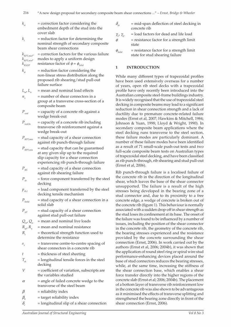
Rib punch-through failure is a localised failure of the concrete rib in the direction of the longitudinal shear, which leaves the base of the shear connector unsupported. The failure is a result of the high stresses being developed in the bearing zone of a stud connector and, due to its proximity to a free concrete edge, a wedge of concrete is broken out of the concrete rib (fi gure 1). This behaviour is normally associated with a sudden drop-off in shear strength as the stud loses its confi nement at its base. The onset of the failure was found to be infl uenced by a number of issues, including the position of the shear connector in the concrete rib, the geometry of the concrete rib, the bearing stresses experienced and the resistance provided by the concrete surrounding the shear connection (Ernst, 2006). In work carried out by the authors (Ernst et al, 2006; 2004b), it was shown that the application of round steel ring or spiral wire stud performance-enhancing devices placed around the base of stud connectors reduces the bearing stresses, while, at the same time, increasing the stiffness of the shear connection base, which enables a shear force transfer directly into the higher regions of the concrete slab (Ernst et al; 2006; 2004b). The placement of a bottom layer of transverse rib reinforcement low in the concrete rib was also shown to be advantageous as it minimised the effects of transverse splitting and strengthened the bearing zone directly in front of the shear connection (Ernst, 2006).
S07-975 Ernst.indd 216S07-975 Ernst.indd 216 15/8/08 4:20:10 PM15/8/08 4:20:10 PM
217“A new design proposal for secondary composite beam shear connections ...” – Ernst, Bridge & Wheeler
Australian Journal of Structural Engineering Vol 8 No 3
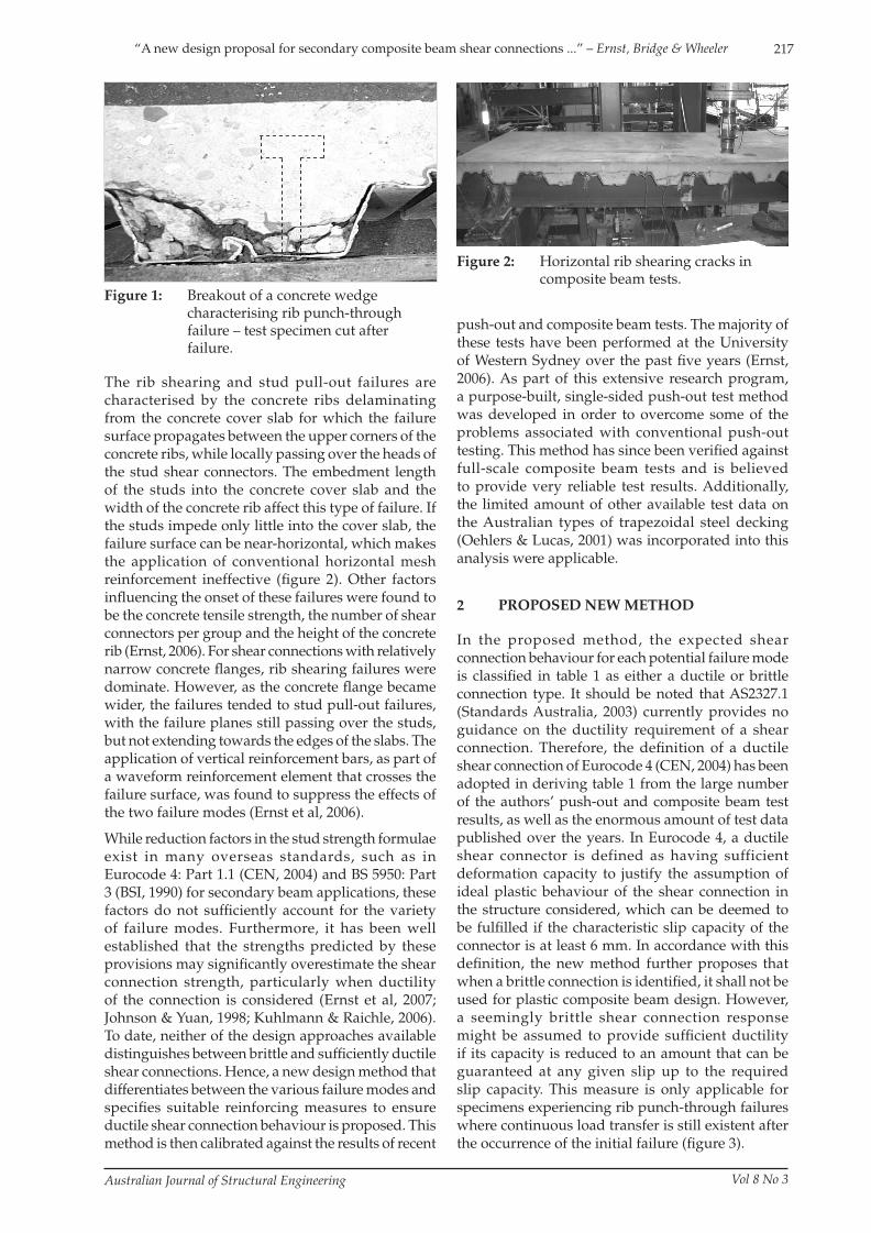
The rib shearing and stud pull-out failures are characterised by the concrete ribs delaminating from the concrete cover slab for which the failure surface propagates between the upper corners of the concrete ribs, while locally passing over the heads of the stud shear connectors. The embedment length of the studs into the concrete cover slab and the width of the concrete rib affect this type of failure. If the studs impede only little into the cover slab, the failure surface can be near-horizontal, which makes the application of conventional horizontal mesh reinforcement ineffective (fi gure 2). Other factors infl uencing the onset of these failures were found to be the concrete tensile strength, the number of shear connectors per group and the height of the concrete rib (Ernst, 2006). For shear connections with relatively narrow concrete fl anges, rib shearing failures were dominate. However, as the concrete fl ange became wider, the failures tended to stud pull-out failures, with the failure planes still passing over the studs, but not extending towards the edges of the slabs. The application of vertical reinforcement bars, as part of a waveform reinforcement element that crosses the failure surface, was found to suppress the effects of the two failure modes (Ernst et al, 2006).
While reduction factors in the stud strength formulae exist in many overseas standards, such as in Eurocode 4: Part 1.1 (CEN, 2004) and BS 5950: Part 3 (BSI, 1990) for secondary beam applications, these factors do not suffi ciently account for the variety of failure modes. Furthermore, it has been well established that the strengths predicted by these provisions may signifi cantly overestimate the shear connection strength, particularly when ductility of the connection is considered (Ernst et al, 2007; Johnson & Yuan, 1998; Kuhlmann & Raichle, 2006). To date, neither of the design approaches available distinguishes between brittle and suffi ciently ductile shear connections. Hence, a new design method that differentiates between the various failure modes and specifi es suitable reinforcing measures to ensure ductile shear connection behaviour is proposed. This method is then calibrated against the results of recent
Figure 1: Breakout of a concrete wedge characterising rib punch-through failure – test specimen cut after failure.
push-out and composite beam tests. The majority of these tests have been performed at the University of Western Sydney over the past fi ve years (Ernst, 2006). As part of this extensive research program, a purpose-built, single-sided push-out test method was developed in order to overcome some of the problems associated with conventional push-out testing. This method has since been verifi ed against full-scale composite beam tests and is believed to provide very reliable test results. Additionally, the limited amount of other available test data on the Australian types of trapezoidal steel decking (Oehlers & Lucas, 2001) was incorporated into this analysis were applicable.
2 PROPOSED NEW METHOD
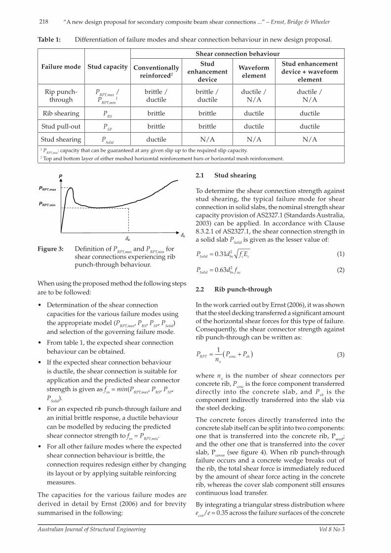
In the proposed method, the expected shear connection behaviour for each potential failure mode is classifi ed in table 1 as either a ductile or brittle connection type. It should be noted that AS2327.1 (Standards Australia, 2003) currently provides no guidance on the ductility requirement of a shear connection. Therefore, the defi nition of a ductile shear connection of Eurocode 4 (CEN, 2004) has been adopted in deriving table 1 from the large number of the authors’ push-out and composite beam test results, as well as the enormous amount of test data published over the years. In Eurocode 4, a ductile shear connector is defined as having sufficient deformation capacity to justify the assumption of ideal plastic behaviour of the shear connection in the structure considered, which can be deemed to be fulfi lled if the characteristic slip capacity of the connector is at least 6 mm. In accordance with this defi nition, the new method further proposes that when a brittle connection is identifi ed, it shall not be used for plastic composite beam design. However, a seemingly brittle shear connection response might be assumed to provide suffi cient ductility if its capacity is reduced to an amount that can be guaranteed at any given slip up to the required slip capacity. This measure is only applicable for specimens experiencing rib punch-through failures where continuous load transfer is still existent after the occurrence of the initial failure (fi gure 3).
Figure 2: Horizontal rib shearing cracks in composite beam tests.
S07-975 Ernst.indd 217S07-975 Ernst.indd 217 15/8/08 4:20:10 PM15/8/08 4:20:10 PM
218
Australian Journal of Structural Engineering Vol 8 No 3
“A new design proposal for secondary composite beam shear connections ...” – Ernst, Bridge & Wheeler
When using the proposed method the following steps
are to be followed:
• Determination of the shear connection
capacities for the various failure modes using
the appropriate model (PRPT,max, PRS, PSP, PSolid)
and selection of the governing failure mode.
• From table 1, the expected shear connection
behaviour can be obtained.
• If the expected shear connection behaviour
is ductile, the shear connection is suitable for
application and the predicted shear connector
strength is given as fvs = min(PRPT,max, PRS, PSP,
PSolid).
• For an expected rib punch-through failure and
an initial brittle response, a ductile behaviour
can be modelled by reducing the predicted
shear connector strength to fvs = PRPT,min.
• For all other failure modes where the expected
shear connection behaviour is brittle, the
connection requires redesign either by changing
its layout or by applying suitable reinforcing
measures.
The capacities for the various failure modes are
derived in detail by Ernst (2006) and for brevity
summarised in the following:
Failure mode Stud capacity
Shear connection behaviour
Conventionally reinforced2
Stud enhancement
device
Waveform element
Stud enhancement device + waveform
element
Rip punch-through
PRPT,max / PRPT,min
1brittle /ductile
brittle /ductile
ductile /N/A
ductile /N/A
Rib shearing PRS brittle brittle ductile ductile
Stud pull-out PSP brittle brittle ductile ductile
Stud shearing PSolid ductile N/A N/A N/A
1 PRPT,min: capacity that can be guaranteed at any given slip up to the required slip capacity.2 Top and bottom layer of either meshed horizontal reinforcement bars or horizontal mesh reinforcement.
Table 1: Differentiation of failure modes and shear connection behaviour in new design proposal.
u
P
c
PRPT,min
PRPT,max
Figure 3: Defi nition of PRPT,max and PRPT,min for shear connections experiencing rib punch-through behaviour.
2.1 Stud shearing
To determine the shear connection strength against
stud shearing, the typical failure mode for shear
connection in solid slabs, the nominal strength shear
capacity provision of AS2327.1 (Standards Australia,
2003) can be applied. In accordance with Clause
8.3.2.1 of AS2327.1, the shear connection strength in
a solid slab PSolid is given as the lesser value of:
2 '0.31Solid bs c cP d f E (1)
20.63Solid bs ucP d f (2)
2.2 Rib punch-through
In the work carried out by Ernst (2006), it was shown
that the steel decking transferred a signifi cant amount
of the horizontal shear forces for this type of failure.
Consequently, the shear connector strength against
rib punch-through can be written as:
1RPT conc sh
x
P Pn
P
(3)
where nx is the number of shear connectors per
concrete rib, Pconc is the force component transferred
directly into the concrete slab, and Psh is the
component indirectly transferred into the slab via
the steel decking.
The concrete forces directly transferred into the
concrete slab itself can be split into two components:
one that is transferred into the concrete rib, Pwed
;
and the other one that is transferred into the cover
slab, Pcover
(see fi gure 4). When rib punch-through
failure occurs and a concrete wedge breaks out of
the rib, the total shear force is immediately reduced
by the amount of shear force acting in the concrete
rib, whereas the cover slab component still ensures
continuous load transfer.
By integrating a triangular stress distribution where
ecrit/e = 0.35 across the failure surfaces of the concrete
S07-975 Ernst.indd 218S07-975 Ernst.indd 218 15/8/08 4:20:10 PM15/8/08 4:20:10 PM
219“A new design proposal for secondary composite beam shear connections ...” – Ernst, Bridge & Wheeler
Australian Journal of Structural Engineering Vol 8 No 3
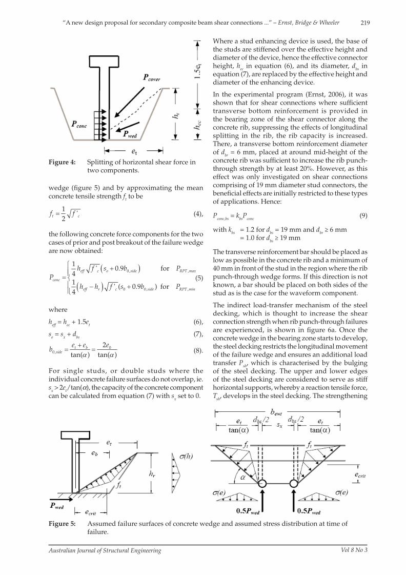
wedge (fi gure 5) and by approximating the mean concrete tensile strength ft to be
1'
2t cf f
(4),
the following concrete force components for the two cases of prior and post breakout of the failure wedge are now obtained:
0, ,
0 0, ,
1' 0.9 for
41
' ( 0.9 ) for4
eff c o side RPT max
conc
eff r c side RPT min
h f s b PP
h h f s b P
(5)
where
heff = hec + 1.5et (6),
so = sx + dbs (7),
00,
2tan( ) tan( )t b
side
e e eb
(8).
For single studs, or double studs where the individual concrete failure surfaces do not overlap, ie.sx > 2et/tan(α), the capacity of the concrete component can be calculated from equation (7) with sx set to 0.
Figure 4: Splitting of horizontal shear force in two components.
Figure 5: Assumed failure surfaces of concrete wedge and assumed stress distribution at time of failure.
Where a stud enhancing device is used, the base of the studs are stiffened over the effective height and diameter of the device, hence the effective connector height, hec in equation (6), and its diameter, dbs in equation (7), are replaced by the effective height and diameter of the enhancing device.
In the experimental program (Ernst, 2006), it was shown that for shear connections where suffi cient transverse bottom reinforcement is provided in the bearing zone of the shear connector along the concrete rib, suppressing the effects of longitudinal splitting in the rib, the rib capacity is increased. There, a transverse bottom reinforcement diameter of dbr = 6 mm, placed at around mid-height of the concrete rib was suffi cient to increase the rib punch-through strength by at least 20%. However, as this effect was only investigated on shear connections comprising of 19 mm diameter stud connectors, the benefi cial effects are initially restricted to these types of applications. Hence:
Pconc,bs = kbsPconc (9)
with kbs = 1.2 for dbs = 19 mm and dbr ≥ 6 mm = 1.0 for dbs ≥ 19 mm
The transverse reinforcement bar should be placed as low as possible in the concrete rib and a minimum of 40 mm in front of the stud in the region where the rib punch-through wedge forms. If this direction is not known, a bar should be placed on both sides of the stud as is the case for the waveform component.
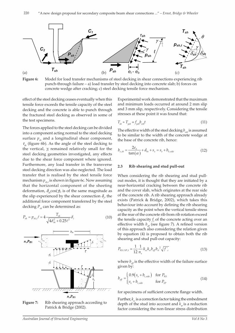
The indirect load-transfer mechanism of the steel decking, which is thought to increase the shear connection strength when rib punch-through failures are experienced, is shown in fi gure 6a. Once the concrete wedge in the bearing zone starts to develop, the steel decking restricts the longitudinal movement of the failure wedge and ensures an additional load transfer Psh, which is characterised by the bulging of the steel decking. The upper and lower edges of the steel decking are considered to serve as stiff horizontal supports, whereby a reaction tensile force, Tsh, develops in the steel decking. The strengthening
S07-975 Ernst.indd 219S07-975 Ernst.indd 219 15/8/08 4:20:11 PM15/8/08 4:20:11 PM
220
Australian Journal of Structural Engineering Vol 8 No 3
“A new design proposal for secondary composite beam shear connections ...” – Ernst, Bridge & Wheeler
effect of the steel decking ceases eventually when this
tensile force exceeds the tensile capacity of the steel
decking and the concrete is able to punch through
the fractured steel decking as observed in some of
the test specimens.
The forces applied to the steel decking can be divided
into a component acting normal to the steel decking
surface psh and a longitudinal shear component,
τsh (fi gure 6b). As the angle of the steel decking to
the vertical, γ, remained relatively small for the
steel decking geometries investigated, any effects
due to the shear force component where ignored.
Furthermore, any load transfer in the transverse
steel decking direction was also neglected. The load
transfer that is realised by the steel tensile force
mechanism psh,t is shown in fi gure 6c. Now assuming
that the horizontal component of the sheeting
deformation, δshcos(γ), is of the same magnitude as
the slip experienced by the shear connection δc, the
additional force component transferred by the steel
decking Psh can be determined as:
, 2 24
4 0.25sh
sh sh t c
sh
TP p
(10)
Psh
C1
C2sh sh
Tsh
Tsh
psh,t
l
sh
Tsh
psh
Psh et - eb
Figure 6: Model for load transfer mechanisms of steel decking in shear connections experiencing rib punch-through failure – a) load transfer by steel decking into concrete slab; b) forces on concrete wedge after cracking; c) steel decking tensile force mechanism.
(b)(a) (c)
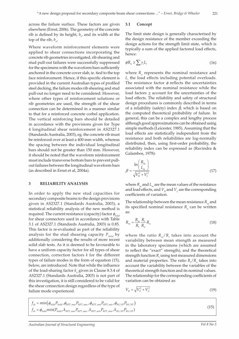
Figure 7: Rib shearing approach according to Patrick & Bridge (2002).
Experimental work demonstrated that the maximum and minimum loads occurred at around 2 mm slip and 3 mm slip, respectively. Considering the tensile stresses at these point it was found that:
Tsh ≈ Tysh = fyshbesht (11)
The effective width of the steel decking besh is assumed to be similar to the width of the concrete wedge at the base of the concrete rib, hence:
, ,
2tan
be sh bs x o b side
eb d s s b
(12)
2.3 Rib shearing and stud pull-out
When considering the rib shearing and stud pull-out modes, it is thought that they are initiated by a near-horizontal cracking between the concrete rib and the cover slab, which originates at the rear side of the concrete rib. A rib shearing approach already exists (Patrick & Bridge, 2002), which takes this behaviour into account by defi ning the rib shearing capacity as the point when the vertical tensile stress at the rear of the concrete rib from rib rotation exceed the tensile capacity ft of the concrete acting over an effective width beff (see fi gure 7). A refi ned version of this approach also considering the relation given by equation (4) is proposed to obtain both the rib shearing and stud pull-out capacity:
2/ ,
1 1'
12RS SP t ec eff rt cx
P k k b bn
f
(13)
where beff is the effective width of the failure surface given by:
,
,
0.9 for
foro t side R
effo t side SP
s b Pb
s b PS
(14)
for specimens of suffi cient concrete fl ange width.
Further, kec is a correction factor taking the embedment depth of the stud into account and kσ is a reduction factor considering the non-linear stress distribution
S07-975 Ernst.indd 220S07-975 Ernst.indd 220 15/8/08 4:20:11 PM15/8/08 4:20:11 PM
221“A new design proposal for secondary composite beam shear connections ...” – Ernst, Bridge & Wheeler
Australian Journal of Structural Engineering Vol 8 No 3
across the failure surface. These factors are given
elsewhere (Ernst, 2006). The geometry of the concrete
rib is defi ned by its height, hr, and its width at the
top of the rib, brt.
Where waveform reinforcement elements were
applied to shear connections incorporating the
concrete rib geometries investigated, rib shearing and
stud pull-out failures were successfully suppressed
for the specimens with the waveform bars suffi ciently
anchored in the concrete cover slab, ie. tied to the top
face reinforcement. Hence, if this specifi c element is
provided in the current Australian types of profi led
steel decking, the failure modes rib shearing and stud
pull-out no longer need to be considered. However,
where other types of reinforcement solutions or
rib geometries are used, the strength of the shear
connection can be determined in a manner similar
to that for a reinforced concrete corbel application.
The vertical reinforcing bars should be detailed
in accordance with the provisions given for Type
4 longitudinal shear reinforcement in AS2327.1
(Standards Australia, 2003), eg. the concrete rib must
be reinforced over at least a 400 mm width, whereas
the spacing between the individual longitudinal
bars should not be greater than 150 mm. However,
it should be noted that the waveform reinforcement
must include transverse bottom bars to prevent pull-
out failures between the longitudinal waveform bars
(as described in Ernst et al, 2004a).
3 RELIABILITY ANALYSIS
In order to apply the new stud capacities for
secondary composite beams to the design provisions
given in AS2327.1 (Standards Australia, 2003), a
statistical reliability analysis of the new method is
required. The current resistance (capacity) factor φSolid
for shear connectors used in accordance with Table
3.1 of AS2327.1 (Standards Australia, 2003) is 0.85.
This factor is re-evaluated as part of the reliability
analysis for the stud shearing capacity PSolid by
additionally considering the results of more recent
solid slab tests. As it is deemed to be favourable to
have a uniform capacity factor for all types of shear
connection, correction factors k for the different
types of failure modes in the form of equation (15),
below, are introduced. Note that while the infl uence
of the load-sharing factor kn given in Clause 8.3.4 of
AS2327.1 (Standards Australia, 2003) is not part of
this investigation, it is still considered to be valid for
the shear connection design regardless of the type of
failure mode experienced.
3.1 Concept
The limit state design is generally characterised by
the design resistance of the member exceeding the
design actions for the strength limit state, which is
typically a sum of the applied factored load effects,
hence:
n iR Li (16)
where Rn represents the nominal resistance and
Li the load effects including potential overloads.
The resistance factor φ reflects the uncertainties
associated with the nominal resistance while the
load factors γi account for the uncertainties of the
load effects. The reliability and safety of structural
design procedures is commonly described in terms
of a reliability (safety) index β, which is based on
the computed theoretical probability of failure. In
general, this can be a complex and lengthy process
although good approximations can be obtained using
simple methods (Leicester, 1985). Assuming that the
load effects are statistically independent from the
resistance and both reliabilities are log-normally
distributed, then, using fi rst-order probability, the
reliability index can be expressed as (Ravindra &
Galambos, 1978):
2 2
ln m
m
R L
RL
V V
(17)
where Rm and Lm are the mean values of the resistance
and load effects, and VR and VL are the corresponding
coeffi cients of variation.
The relationship between the mean resistance Rm and
its specifi ed nominal resistance Rn can be written
as:
m tm n
t n
R RR R
R R (18)
where the ratio Rm/Rt takes into account the
variability between mean strength as measured
in the laboratory specimens (which are assumed
to refl ect the “exact” strength), and the theoretical
strength function Rt using test measured dimensions
and material properties. The ratio Rt/Rn takes into
account the variability between the variables of the
theoretical strength function and its nominal values.
The relationship for the corresponding coeffi cients of
variation can be obtained as:
2 2R rV V V t (19)
, , , , / /
, , , , / /
, , ,
( , , ,ds Solid Solid RPT max RPT max RPT min RPT min RS SP RS SP
ds Solid Solid RPT max RPT max RPT min RPT min RS SP RS SP
f min P P P P
f min P k P k P k P )(15)
S07-975 Ernst.indd 221S07-975 Ernst.indd 221 15/8/08 4:20:12 PM15/8/08 4:20:12 PM
222
Australian Journal of Structural Engineering Vol 8 No 3
“A new design proposal for secondary composite beam shear connections ...” – Ernst, Bridge & Wheeler
where Vδ is the coeffi cient of variation for the ratio
of test results to theoretical strength prediction, ie.
the scatter of the test results, and Vrt the coeffi cient of
variation of the variables of the theoretical strength
function.
The mean load effect Lm and the corresponding
coeffi cient of variation VL are generally dependent
on the ratio of dead load G to live load Q. The mean
load effect Lm can be expressed as the sum of the mean
dead and live loads, Gm and Qm, where:
Lm = Gm + Qm (20)
The nominal load effects given in limit state designs
are typically of the form:
Ln = γGGn + γQQn (21)
where γG and γQ are determined for the appropriate
combination of action investigated at the ultimate
limit state. If a factor r for the ratio of the nominal
dead load to the combined total load is introduced,
ie.
n
n n
Gr
G Q (22),
the mean load effect can be written as a function of
this ratio:
1
1
m m
n nmm n
n G Q
G Qr rG QL
L LL r r nL
(23)
The coeffi cient of variation can also be expressed as a
function of the independent coeffi cients of variation
for dead loads VG and live loads VQ using the ratio
r of dead to total load given by equation (22) gives
equation (24), below.
A detailed investigation into the load combination
formulae for Australian Limit State Codes (Pham,
1985a) found that the dead loads are typically
underestimated and their statistical parameters to
be the following:
1.05m
n
GG
; VG = 0.10.
For the live loads effects on offi ce fl oors, the following
statistical parameters were given for floor sizes
typical for composite beam applications:
0.70m
n
; VQ = 0.26.
For fl oor applications, the load factors to be considered for the ultimate limit state in accordance with AS/NZS1170.0 (Standards Australia, 2002) are:
1.35; 0 1for
1.2; 1.5 all otherG Q
Q Q
r
r
(25)
3.2 Determination of design resistance factors
In the following, the resistance factors φ and correction factors k are determined for the individual failure modes in order to provide an appropriate target reliability index β
0. The relation between resistance
factor and target reliability index is obtained by substituting the condition of equations (16) and (21) into equation (17) so that:
02 2
/ln
/m n
m n
R L
R RL L
V V
(26)
No target reliability index is given in the design provisions of AS2327.1 (Standards Australia, 2003). In an earlier reliability study on shear connections in simply supported beams, reliability indices ranging from β = 4.5-5.5 were established (Pham, 1984). However, the study was based on an earlier shear connection design method (Pham, 1979), which provided signifi cantly lower stud strengths. Other Australian target index reliabilities were set to β
0
= 3.5 for steel members (Pham, 1985b), β0 = 2.5 for
members of cold-formed steel structures (Standards Australia, 1998), and β
0 = 3.5 for joints and fasteners
in cold formed steel structures (Standards Australia, 1998). Overseas, target indices of β
0 = 3.8 for the
determination of the various Eurocode models (see Johnson & Huang, 1994) or β
0 = 3.0 for composite
members in the AISC specifi cations (see Rambo-Roddenberry, 2002) were used. It was decided to calibrate the design resistance factors against a target reliability index of β
0 = 3.5, which represents
a probability of failure of 2.3 x 10⁻⁴. It should be noted that a different target reliability index would obviously lead to other design capacity factors than the ones presented below.
3.2.1 Solid slab applications
The comparison of the test results of a total of 163
2 2
22 1
(1 )
m mG Q
m G m Q n nL
m m m
n n
G Qr V r V
G V Q V G QV
L G Qr rG Q
(24)
S07-975 Ernst.indd 222S07-975 Ernst.indd 222 15/8/08 4:20:13 PM15/8/08 4:20:13 PM
223“A new design proposal for secondary composite beam shear connections ...” – Ernst, Bridge & Wheeler
Australian Journal of Structural Engineering Vol 8 No 3
solid slab push-out test published in Ernst (2006) with
the theoretical strength functions given by equations
(1) and (2) was carried out. This study used either
measured material properties or mean values for
all variables provided and resulted in the statistical
parameters shown in table 2. Assuming all basic
variables Xi of the theoretical strength functions to
be mutually uncorrelated, thereby yielded values
of the means of the theoretical functions over the
nominal functions, Pt/Pn. Further, the coeffi cients of
variation Vrt were determined by using the fi rst order
Taylor expansion of the theoretical strength function
about the mean:
2
2,2
1,
1 nt
rt Xi i mit m i
PV V
P XX
(27)
The means and coefficients of variation of the
individual variables were generally determined from
measurements on test specimens or material property
tests. However, the statistical parameters for the
concrete strength were chosen in accordance with the
assessment undertaken in Pham (1983), which also
accounted for the infl uences of curing procedures,
workmanship, and the differences between cylinder
strength and strength of the concrete cores taken from
the fi nished structure.
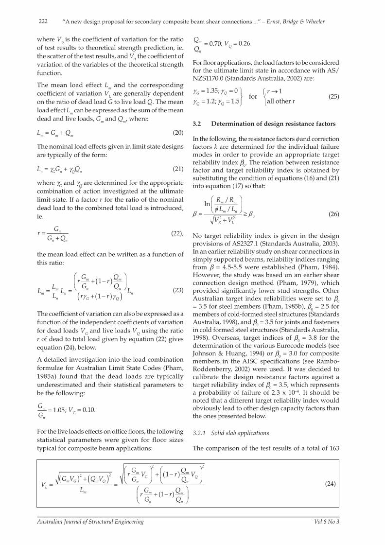
It can be seen that the parameters are much more
favourable for equation (2), ie. the provision
considering the stud shank strength. The results
of the calculated reliability indices assuming the
load factors given by equation (25) are shown for
the different ratios of dead load to total combined
load r in fi gure 8. Considering the design resistance
factor of φSolid = 0.85 as given in AS2327.1 (Standards
Australia, 2003), the target reliability index of β0 =
3.5 for equation (1) is not always reached for the
typical loading ratios of composite beams (r ≈ 0.4-0.6).
Equation n Pm/Pt Vδ Pt/Pn Vrt
(1) 87 1.22 0.135 0.99 0.136
(2) 76 1.23 0.102 1.13 0.063
Table 2: Statistical parameters for evaluation of equations (1) and (2).
Figure 8: Variation of reliability indices for the solid slab strength.
Strength function
Studs in pan
n Pm/Pt Vδ Pt/Pn Vrt k 3
PRPT,max
Singles 15 1.08 0.141 1.02-1.09 0.141-0.230 0.70
Pairs 22 1.02 0.132 1.22 0.121-0.213 0.85
PRPT,min
Singles 12 1.20 0.147 1.07-1.15 0.145-0.221 0.85
Pairs 7 1.20 0.239 1.28-1.32 0.123-0.206 0.85
PRS/SP
Singles 9 1.08 0.136 0.92-0.93 0.214-0.269 0.60
Pairs 19 1.04 0.129 1.06-1.11 0.187-0.253 0.703 correction factor to be used in combination with resistance capacity factor of φ = 0.8
Table 3: Statistical parameters of shear connections in composite slab applications.
A smaller design resistance factor of φSolid = 0.80, which generally exceeds the target reliability index for equation (1) in this range, is proposed for shear connections experiencing stud shearing failures, eg. solid slab shear connections. This new design resistance factor aligns well with the stud strength design of BS5950.3 (BSI, 1990) and Eurocode 4 (CEN, 2004), where design capacity factors of 1/1.25 (= 0.8) are applied.
3.2.2 Composite slab applications
The statistical parameters (including the sample size n) for the comparison of a total of 84 push-out tests on composite slab specimens given in Ernst (2006), which experienced premature concrete-related failure modes with the theoretical strength functions given by equations (3), (5), (10) and (13), are shown in table 3. It was decided to divide the analysis into two groups, one being for the confi guration of single studs in a concrete rib, and the other being for stud pairs for each failure mode experienced. As the new method does not distinguish between shear connections where the studs have been directly welded through the steel decking and those where the decking was pre-holed, no further differentiation of the test results, which included both layouts, was deemed to be necessary.
The parameters of the strength functions given in table 3 account for shear connections of 19 mm stud diameter; stud enhancing devices of 76 mm diameter; steel decking heights of 50 mm ≤ hr ≤ 80 mm; stud
S07-975 Ernst.indd 223S07-975 Ernst.indd 223 15/8/08 4:20:13 PM15/8/08 4:20:13 PM
224
Australian Journal of Structural Engineering Vol 8 No 3
“A new design proposal for secondary composite beam shear connections ...” – Ernst, Bridge & Wheeler
positions in the sheeting pan being in the range of 30 mm ≤ eb ≤ 110 mm, and 60 mm ≤ et ≤ 140 mm; and, where applicable, transverse stud spacings between 80 mm ≤ sx ≤ 120 mm. In the specimens investigated, it was found that the proportion of the loads directly transferred into the concrete slabs to the total shear capacity was in the range of 0.60 ≤ Pconc/(nxPRPT,max) ≤ 0.85 for the maximum rib punch-through strength, and in the range of 0.30 ≤ Pconc/(nxPRPT,min) ≤ 0.60 for the minimum strength. These limits are also considered in the determination of the strength function parameters.
The applications of the design resistance factor in combination with the corresponding correction factor k in accordance with equation (15) provide safety levels similar to solid slab applications. The correction factors were generally chosen so that the safety indices of the lower limits exceeded the target reliability index in the composite beam load application range of r = 0.4-0.6. It can be seen that the coeffi cients of variation representing the scatter of the strength function are signifi cantly larger compared to the stud shearing provisions. This can be attributed to the more irregular effects of concrete cracking, which are considered in these functions. Hence, the nominal strength functions need to be signifi cantly reduced, ie. relatively low correction factors need to be applied to ensure a similar level of safety. The correction factors for rib shearing and stud pullout failures were generally lower than those for rib punch-through failure.
4 SIMPLIFIED DESIGN FOR AUSTRALIAN TRAPEZOIDALSTEEL DECKING GEOMETRIES
It is acknowledged that the new design method proposed is rather complex to use, and that reduction factors applied to the solid slab shear connections strength provide by far the most convenient approach to take into account the infl uence of steel decking.
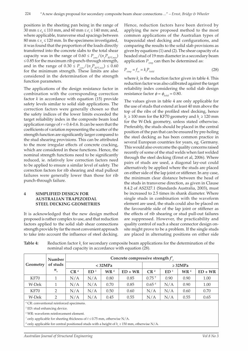
Hence, reduction factors have been derived by applying the new proposed method to the most common applications of the Australian types of trapezoidal steel decking and confi gurations, and comparing the results to the solid slab provisions as given by equations (1) and (2). The shear capacity of a headed stud of 19 mm diameter in a secondary beam application Psimp can then be determined as:
Psimp = fvs = ktPSolid (28)
where kt is the reduction factor given in table 4. This reduction factor was also calibrated against the target reliability index considering the solid slab design resistance factor φ = φSolid = 0.80.
The values given in table 4 are only applicable for the use of studs that extend at least 40 mm above the top of the ribs of the profi led steel decking, hence hc ≥ 100 mm for the KF70 geometry and hc ≥ 120 mm for the W-Dek geometry, unless stated otherwise. Preferably, the studs should be placed in the central position of the pan that can be ensured by pre-holing the steel decking as has been common practice in several European countries for years, eg. Germany. This would also overcome the quality concerns raised recently of some of the stud welds when fast welded through the steel decking (Ernst et al, 2006). Where pairs of studs are used, a diagonal lay-out could alternatively be applied where the studs are placed on either side of the lap joint or stiffener. In any case, the minimum clear distance between the head of the studs in transverse direction, as given in Clause 8.4.2 of AS2327.1 (Standards Australia, 2003), must be increased to 2.5 times its shank diameter. Where single studs in combination with the waveform element are used, the studs could also be placed on the favourable side of the lap joint or stiffener as the effects of rib shearing or stud pull-out failures are suppressed. However, the practicability and quality control of such a shear connector design on-site might prove to be a problem. If the single studs are placed in alternating positions on either side
GeometryNumber of studs
nx
Concrete compressive strength f’c
< 32MPa ≥ 32MPa
CR 4 ED 5 WR 6 ED + WR CR 4 ED 5 WR 6 ED + WR
KF70 1 N/A N/A 0.80 0.85 0.75 7 0.90 0.90 1.00
W-Dek 1 N/A N/A 0.70 0.85 0.65 8 N/A 0.90 1.00
KF70 2 N/A N/A 0.50 0.60 N/A N/A 0.60 0.70
W-Dek 2 N/A N/A 0.45 0.55 N/A N/A 0.55 0.654 CR: conventional reinforced specimens.5 ED: stud enhancing device.6 WR: waveform reinforcement element.7 only applicable for sheeting thickness of t ≤ 0.75 mm, otherwise N/A.8 only applicable for central positioned studs with a height of hc ≥ 150 mm, otherwise N/A.
Table 4: Reduction factor kt for secondary composite beam applications for the determination of the nominal stud capacity in accordance with equation (28).
S07-975 Ernst.indd 224S07-975 Ernst.indd 224 15/8/08 4:20:14 PM15/8/08 4:20:14 PM
225“A new design proposal for secondary composite beam shear connections ...” – Ernst, Bridge & Wheeler
Australian Journal of Structural Engineering Vol 8 No 3
of the lap joint, as suggested by Eurocode 4 (CEN, 2004), the reduction factors of table 4 should not be applied as the shear connectors positioned on the unfavourable side might experience a signifi cantly reduced strength or slip capacity. The values given in table 4 were derived for high strength G550 sheeting material with nominal thicknesses ranging from 0.6 to 1.0 mm.
The Type 4 longitudinal shear reinforcement provisions of Chapter 9.8 of AS2327.1 (Standards Australia, 2003) additionally need be considered where the shear connection is close to a free concrete edge in transverse direction. They are generally deemed to be satisfi ed where the waveform element is provided. In all other cases where the reduction factors of table 4 are applied, additional Type 4 shear reinforcement needs to be provided where the distance of the transverse edge of the concrete slab to the nearest shear connector is less than 2.5 times the height of the shear connector.
5 CONCLUSIONS
On the basis of an extensive evaluation of available test data on the behaviour of shear connections incorporating Australian types of profiled steel decking, a new design method has been proposed that differentiates between the various failure modes identified and specifies the suitable reinforcing measures to ensure ductile shear connection behaviour. One of the features of this new proposal is to allow for the occurrence of some of the brittle failure modes as long as a minimum capacity can be guaranteed at any given slip up to the required slip capacity. The new method was found to provide increased reliability and much reduced scatter for the strength prediction of stud connectors. However, as a large number of parameters need to be considered, the practicality of this method is somewhat restricted. Based on this method, simple strength reduction factors have been determined for the most common applications of existing types of trapezoidal Australian decking geometries. It should be noted that tight limits for the application of these reduction factors apply, and their application should strictly be restricted to the specifi ed types of shear connections. Both, the general and the simplifi ed method were calibrated to provide a similar level of safety as the current AS2327.1 (Standards Australia, 2003) design provisions for stud connectors. Based on the reliability analysis performed, it is recommended to reduce the resistance factor φ for stud shear connectors designed to AS2327.1 (Standards Australia, 2003) from 0.85-0.80 to obtain an appropriate level of safety.
REFERENCES
British Standards Institution (BSI), 1990, “Structural
use of steelwork in building, Part 3. Design in composite construction”, BS 5950, Part 3.
CEN, 2004, “Design of composite steel and concrete structures, Part 1-1: General rules and rules for buildings”, Eurocode 4, European Committee for Standardization (CEN).
Ernst, S. 2006, “Factors affecting the behaviour of the shear connection of steel-concrete composite beams”, PhD thesis, University of Western Sydney, Sydney.
Ernst, S., Patrick, M., Bridge, R. Q. & Wheeler, A. 2004a, “Reinforcement requirements for secondary composite beams incorporating trapezoidal decking”, Composite Construction in Steel and Concrete V, Kruger National Park, South Africa, pp. 236-246.
Ernst, S., Patrick, M. & Wheeler, A. 2004b, “Novel shear stud component for secondary composite beams”, 18th Australasian Conference on the Mechanics of Structures and Materials, Perth, Australia, pp. 63-69.
Ernst, S., Bridge, R. Q. & Patrick, M. 2006, “Behaviour of the longitudinal shear connection in secondary composite beams incorporating trapezoidal steel decking”, 19th Australasian Conference on the Mechanics of Structures and Materials, Christchurch, New Zealand, pp. 49-56.
Ernst, S., Bridge, R. Q. & Wheeler, A. 2007, “Strength of headed stud shear connection in composite beams”, Australian Journal of Structural Engineering, Vol. 7, No. 2, pp. 111-122.
Hawkins, N. M. & Mitchell, D. 1984, “Seismic response of composite shear connections”, Journal of Structural Engineering, Vol. 110, No. 9, pp. 2120-2136.
Johnson, R. P. & Huang, D. 1994, “Calibration of safety factors γm for composite steel and concrete beams in bending”, Proceedings of the Institution of Civil Engineers, Structures & Buildings, Vol. 104, pp. 193-203.
Johnson, R. P. & Yuan, H. 1998, “Existing rules and new tests for stud shear connectors in throughs of profi led steel sheeting”, Proceedings of the Institution of Civil Engineers: Structures & Buildings, Vol. 128, pp. 244-251.
Kuhlmann, U. & Raichle, J. 2006, “Schubtragfähigkeit von Verbundträgern mit Profi lblechen nach Eurocode 4 Teil 1-1”, Nr. 2006-9X, Universität Stuttgart, Institut für Konstruktion und Entwurf.
Leicester, R. H. 1985, “Computation of a safety index” Civil Engineering Transactions, IEAust., Vol. CE27, No. 1, pp. 55-61.
Lloyd, R. M. & Wright, H. D. 1990, “Shear connection
S07-975 Ernst.indd 225S07-975 Ernst.indd 225 15/8/08 4:20:14 PM15/8/08 4:20:14 PM
226
Australian Journal of Structural Engineering Vol 8 No 3
“A new design proposal for secondary composite beam shear connections ...” – Ernst, Bridge & Wheeler
between composite slabs and steel beams”, Journal Construct. Steel Research, Vol. 15, pp. 255-285.
Oehlers, D. J. & Lucas, B. 2001, “KingFloor-70 Stud Shear Connector Tests”, C200505, Adelaide University, Adelaide.
Patrick, M. & Bridge, R. Q. 2002, “Shear connection in composite beams incorporating open-through profi le decks”, Advances in Steel Structures, Hong Kong, China, pp. 519-526.
Pham, L. 1979, “Design strength of stud shear connectors”, Australian Road Research, Vol. 9, No. 4, pp. 16-22.
Pham, L. 1983, “Reliability analysis of reinforced concrete and composite column sections”, Symposium on Concrete: The Material for Tomorrow’s Demands, Perth, pp. 100-104.
Pham, L. 1984, “Reliability analysis of simply-supported composite beams”, Civil Engineering Transactions, Vol. CE26, No. 1, pp. 41-47.
Pham, L. 1985a, “Load combinations and probabilistic load models for limit state codes”, Civil Engineering Transactions, IEAust., Vol. CE27, No. 1, pp. 62-67.
Pham, L. 1985b, “Safety indices for steel beams and columns designed to AS 1250-1981”, Civil Engineering Transactions, IEAust., Vol. CE27, No. 1, pp. 105-110.
Rambo-Roddenberry, 2002, “Behaviour and strength of welded stud shear connectors”, PhD thesis, Virginia Polytechnic Institute and State University, Blacksburg, USA.
Ravindra, M. K. & Galambos, T. V. 1978, “Load and resistance factor design for steel”, Journal of the Structural Division, Vol. 104, No. ST9, pp. 1337-1353.
Standards Austral ia , 1998, “Cold-formed steel structures-Commentary”, AS/NZS 4600 Supp1:1998.
Standards Australia, 2002, “Structural design actions, Part 0: General principles”, AS/NZS 1170.0:2002.
Standards Australia, 2003, “Composite Structures, Part 1: Simply Supported Beams”, AS 2327.1-2003.
S07-975 Ernst.indd 226S07-975 Ernst.indd 226 15/8/08 4:20:14 PM15/8/08 4:20:14 PM
227“A new design proposal for secondary composite beam shear connections ...” – Ernst, Bridge & Wheeler
Australian Journal of Structural Engineering Vol 8 No 3
STEFAN ERNST
After Dr Stefan Ernst (Dipl-Ing, PhD) graduated from Darmstadt University of Technology in 2002, he gained experience as a structural design and consulting engineer at stahl+verbundbau gmbh in his native Germany. From 2003-2007, he worked as a research assistant at the Construction Technology and Research Group at the University of Western Sydney, where he completed his PhD degree in 2007. His research focused on the fi elds of steel and composite steel-concrete structures. Stefan is currently working as a structural design engineer for the Sydney consulting fi rm MPN Group Pty Ltd.
RUSSELL BRIDGE
Emeritus Professor Russell Bridge (BE, PhD, FIEAust, FASCE, FICE, FIABSE) is both a structural engineer and a university academic/researcher. He has a wide experience in steel, concrete and composite steel-concrete structures, and has published over 240 research papers. His interests have covered a wide range of topics in the fi eld of structural engineering. This is refl ected in the direct and major contributions that he has made to the recent Australian limit states codes AS2327 Composite Structures, AS3600 Concrete Structures, AS4100 Steel Structures and AS5100 Bridge Design.
Russell’s research areas have included the behaviour of composite steel and concrete construction; the stability of steel members and frames; the reliability basis of design; buckling of thin-walled steel elements; the modelling of reinforced and prestressed concrete structures; advanced methods of analysis and design; and the infl uence of imperfections on structural behaviour. He has been extensively consulted by both private industry and government authorities on a wide range of structural engineering problems.
ANDREW WHEELER
Dr Andrew Wheeler (BE, PhD) has worked in the structural engineering community as both a design engineer and a researcher. He has worked primarily in the fi elds of steel, concrete and composite steel concrete structures, and has published over 40 research papers. His work in the fi eld of composite and concrete structures has led to signifi cant contributions to both national and international design standards, including AS 3600 Concrete Structures. His research areas include design and behaviour of concrete/composite columns, composite slabs/beams, crack control in reinforced concrete structures, the behaviour of high strength steel members, and advance methods of structural analysis.
S07-975 Ernst.indd 227S07-975 Ernst.indd 227 15/8/08 4:20:14 PM15/8/08 4:20:14 PM
Related Documents