Institut f¨ ur Informatik der Technischen Universit¨ at M¨ unchen A Client-Server Architecture for Customized Graphical User Interfaces on the Client Side Roland Haratsch Vollst¨andiger Abdruck der von der Fakult¨ at f¨ ur Informatik der Technischen Universit¨ at M¨ unchen zur Erlangung des akademischen Grades eines Doktors der Naturwissenschaften (Dr. rer. nat.) genehmigten Dissertation. Vorsitzende: Univ.-Prof. G. J. Klinker, Ph.D. Pr¨ ufer der Dissertation: 1. Univ.-Prof. Dr. Dr.h.c. J. Eickel 2. Univ.-Prof. Dr. H. M. Gerndt Die Dissertation wurde am 29.04.2009 bei der Technischen Universit¨ at M¨ unchen eingereicht und durch die Fakult¨at f¨ ur Informatik am 29.10.2009 angenommen.

Welcome message from author
This document is posted to help you gain knowledge. Please leave a comment to let me know what you think about it! Share it to your friends and learn new things together.
Transcript

Institut fur Informatik
der Technischen Universitat Munchen
A Client-Server Architecture for Customized
Graphical User Interfaces on the Client Side
Roland Haratsch
Vollstandiger Abdruck der von der Fakultat fur Informatik der Technischen
Universitat Munchen zur Erlangung des akademischen Grades eines
Doktors der Naturwissenschaften (Dr. rer. nat.)
genehmigten Dissertation.
Vorsitzende: Univ.-Prof. G. J. Klinker, Ph.D.
Prufer der Dissertation:
1. Univ.-Prof. Dr. Dr.h.c. J. Eickel
2. Univ.-Prof. Dr. H. M. Gerndt
Die Dissertation wurde am 29.04.2009 bei der Technischen Universitat
Munchen eingereicht und durch die Fakultat fur Informatik am 29.10.2009
angenommen.


Abstract
This thesis treats the generation of customized graphical user interfaces for restricted client de-vices, which are mainly characterized by severe limitations in terms of processing power, availablememory, and input/output interface. Since the late 1990s devices like mobile phones, PDAs, etc.have proliferated in the consumer and embedded market. In the beginning, these limited devicescould hardly access Web content and other network services on the application layer, since theInternet technology and its provided services like the World Wide Web (WWW) have originallyassumed networked clients with sufficient system resources. Whereas the industry has mainlyconcentrated on drastically increasing the hardware capabilities of such handheld devices, theapproach of this thesis takes particularly the severe hardware restrictions into consideration. Theattempt to save hardware resources as much as possible has become an essential part of the emerg-ing initiative called Green Computing. As a result, this thesis proposes a uniform client-serverarchitecture that enables a wide variety of client-devices to access Web content, from very low-end devices like wristwatches to mobile phones and even high-end workstations. The generationof graphical user interfaces for restricted clients with small displays imposes technical as well asergonomic challenges. This thesis focuses on the technical aspects.
On the client side, a new and low-level binary format for describing graphical user interfaces ispresented. This format is independent of any particular layout design and takes into accountfrom scratch the different rendering and display capabilities of the restricted client devices byallowing user interface descriptions of different complexity. This new format does not dependon other formats and technologies. In addition, a new virtual machine, called Client VirtualMachine (CVM), is introduced which runs on the client device. The main tasks of the CVMare to communicate with the server, called CVM packet server, and to interpret the receivedCVM packets, which contain the user interface descriptions. The main design goal of the CVMis a simple and modular architecture so that small and restricted client devices can implement itwithout large efforts. In contrast to the recent developments in the area of handheld, mobile, andembedded devices, which came along with rising costs for their development and manufacturing,the CVM focuses particularly on very cheap client devices for the mass market to keep the per-unitmanufacturing costs as low as possible.
On the server side, an exemplary framework for the generation of client-specific user interfaces ispresented. After a client request, client-specific user interfaces are generated from an abstract userinterface description and from the obtained profile data about the client capabilities such as screendimensions, memory size, etc. The service providers can decide on their own how they createappropriate CVM packets for the requesting clients. This thesis proposes a technical platformthat leaves the service providers as much flexibility and also responsibility in layout-related andother ergonomic issues as possible.
For the client-server communication a simple application protocol, called the CVM packet trans-fer protocol (CPTP), is proposed. It runs on top of the transport layer and is a very “thin”counterpart to the HTTP protocol, which is used in the WWW. Mainly, it consists only of a fewprotocol methods for requesting and delivering CVM packets and for sending profile data aboutthe client capabilities.
The proposed concepts do not depend on Java-, XML-, or WAP-based technologies. They havebeen implemented in the C programming language and are demonstrated by several examples.

Acknowledgment
This thesis would not have been possible without the support of many people. First of all,I would like to thank my supervisor Prof. Jurgen Eickel for the opportunity to work onthis dissertation at his chair. I am grateful for his support and guidance during the courseof this work.
I would also like to thank the members of the doctoral committee, Prof. Michael Gerndtand Prof. Gudrun Klinker, for their assistance and valuable comments.
In addition, I have also benefited from the technical discussions with my former colleaguesat the chair, in particular Dr. Alfons Brandl and Dr. Aurel Huber. Special thanks go toMr. Franz Hassmann for his administrative support and encouragement.
Finally, I thank my family for their support in every respect.

Contents
1 Introduction 11.1 Problem . . . . . . . . . . . . . . . . . . . . . . . . . . . . . . . . . . . . . 11.2 Client-Specific Service and Content Adaptation . . . . . . . . . . . . . . . 31.3 Thesis Scope — Client-Specific Graphical User Interfaces . . . . . . . . . . 51.4 Related Work — Overview . . . . . . . . . . . . . . . . . . . . . . . . . . . 61.5 Summary of the Chapters . . . . . . . . . . . . . . . . . . . . . . . . . . . 10
2 Proposed Client-Server Architecture — Overview 122.1 Main Components of Interactive Network Services . . . . . . . . . . . . . . 122.2 Client Side . . . . . . . . . . . . . . . . . . . . . . . . . . . . . . . . . . . 13
2.2.1 User Interface Description Format . . . . . . . . . . . . . . . . . . . 132.2.1.1 Compactness vs. Scalability . . . . . . . . . . . . . . . . . 142.2.1.2 Declarative vs. Operational . . . . . . . . . . . . . . . . . 20
2.2.2 Client Virtual Machine (CVM) . . . . . . . . . . . . . . . . . . . . 242.3 Server Side . . . . . . . . . . . . . . . . . . . . . . . . . . . . . . . . . . . 252.4 Communication Protocol . . . . . . . . . . . . . . . . . . . . . . . . . . . . 29
3 Client Virtual Machine (CVM) 313.1 Core . . . . . . . . . . . . . . . . . . . . . . . . . . . . . . . . . . . . . . . 32
3.1.1 Data Types . . . . . . . . . . . . . . . . . . . . . . . . . . . . . . . 323.1.2 Operation Modes . . . . . . . . . . . . . . . . . . . . . . . . . . . . 333.1.3 Register Stack . . . . . . . . . . . . . . . . . . . . . . . . . . . . . 343.1.4 Memory . . . . . . . . . . . . . . . . . . . . . . . . . . . . . . . . . 36
3.1.4.1 Data and Code . . . . . . . . . . . . . . . . . . . . . . . . 373.1.4.2 Stack . . . . . . . . . . . . . . . . . . . . . . . . . . . . . 383.1.4.3 Heap . . . . . . . . . . . . . . . . . . . . . . . . . . . . . . 41
3.1.5 Error Handling . . . . . . . . . . . . . . . . . . . . . . . . . . . . . 413.1.5.1 Error Processing . . . . . . . . . . . . . . . . . . . . . . . 413.1.5.2 Error Codes . . . . . . . . . . . . . . . . . . . . . . . . . . 42
3.1.6 Event Handling . . . . . . . . . . . . . . . . . . . . . . . . . . . . . 453.1.6.1 Event Processing . . . . . . . . . . . . . . . . . . . . . . . 463.1.6.2 Event Registers . . . . . . . . . . . . . . . . . . . . . . . . 473.1.6.3 Special Events . . . . . . . . . . . . . . . . . . . . . . . . 483.1.6.4 Event Codes . . . . . . . . . . . . . . . . . . . . . . . . . 49
3.1.7 History Buffer . . . . . . . . . . . . . . . . . . . . . . . . . . . . . . 523.1.8 Bookmarks Menu . . . . . . . . . . . . . . . . . . . . . . . . . . . . 563.1.9 Interval Timer . . . . . . . . . . . . . . . . . . . . . . . . . . . . . . 573.1.10 Runtime Behavior . . . . . . . . . . . . . . . . . . . . . . . . . . . . 58
3.2 Visual . . . . . . . . . . . . . . . . . . . . . . . . . . . . . . . . . . . . . . 75
i

ii Contents
3.2.1 Graphics State . . . . . . . . . . . . . . . . . . . . . . . . . . . . . 763.2.2 Graphics Primitives . . . . . . . . . . . . . . . . . . . . . . . . . . . 783.2.3 Fonts . . . . . . . . . . . . . . . . . . . . . . . . . . . . . . . . . . . 79
3.3 Keyboard, Mouse . . . . . . . . . . . . . . . . . . . . . . . . . . . . . . . . 813.4 Network . . . . . . . . . . . . . . . . . . . . . . . . . . . . . . . . . . . . . 823.5 Libraries . . . . . . . . . . . . . . . . . . . . . . . . . . . . . . . . . . . . . 833.6 Home Menu . . . . . . . . . . . . . . . . . . . . . . . . . . . . . . . . . . . 863.7 CVM Profile . . . . . . . . . . . . . . . . . . . . . . . . . . . . . . . . . . . 893.8 CVM Packet . . . . . . . . . . . . . . . . . . . . . . . . . . . . . . . . . . . 933.9 Instruction Set . . . . . . . . . . . . . . . . . . . . . . . . . . . . . . . . . 98
3.9.1 Overview . . . . . . . . . . . . . . . . . . . . . . . . . . . . . . . . 993.9.2 Reference . . . . . . . . . . . . . . . . . . . . . . . . . . . . . . . . 100
3.10 Implementation Notes . . . . . . . . . . . . . . . . . . . . . . . . . . . . . 1173.11 Related Work . . . . . . . . . . . . . . . . . . . . . . . . . . . . . . . . . . 123
4 CVM Packet Transfer Protocol (CPTP) 1274.1 Message Format . . . . . . . . . . . . . . . . . . . . . . . . . . . . . . . . . 1274.2 Protocol Methods . . . . . . . . . . . . . . . . . . . . . . . . . . . . . . . . 1284.3 Implementation Notes . . . . . . . . . . . . . . . . . . . . . . . . . . . . . 1314.4 Example . . . . . . . . . . . . . . . . . . . . . . . . . . . . . . . . . . . . . 131
5 CVM Packet Server (CVMPS) 1355.1 Abstract User Interface Description (AUI) . . . . . . . . . . . . . . . . . . 135
5.1.1 Concrete Syntax . . . . . . . . . . . . . . . . . . . . . . . . . . . . 1365.1.2 Abstract Syntax . . . . . . . . . . . . . . . . . . . . . . . . . . . . . 1475.1.3 Builtin Functions . . . . . . . . . . . . . . . . . . . . . . . . . . . . 1485.1.4 Example . . . . . . . . . . . . . . . . . . . . . . . . . . . . . . . . . 149
5.2 Session Manager . . . . . . . . . . . . . . . . . . . . . . . . . . . . . . . . 1545.2.1 Session Data . . . . . . . . . . . . . . . . . . . . . . . . . . . . . . . 1555.2.2 Main Loop . . . . . . . . . . . . . . . . . . . . . . . . . . . . . . . . 156
5.3 Service Generator . . . . . . . . . . . . . . . . . . . . . . . . . . . . . . . . 1595.3.1 Fixed Part of the Service Instance . . . . . . . . . . . . . . . . . . . 1605.3.2 Generated Part of the Service Instance . . . . . . . . . . . . . . . . 161
5.4 CVM Packet Generator . . . . . . . . . . . . . . . . . . . . . . . . . . . . . 1635.5 CVM User Interface (CVMUI) . . . . . . . . . . . . . . . . . . . . . . . . . 166
5.5.1 Global Structure . . . . . . . . . . . . . . . . . . . . . . . . . . . . 1665.5.2 Page . . . . . . . . . . . . . . . . . . . . . . . . . . . . . . . . . . . 1705.5.3 (Single-Line) Text . . . . . . . . . . . . . . . . . . . . . . . . . . . . 1775.5.4 Text Paragraph . . . . . . . . . . . . . . . . . . . . . . . . . . . . . 1795.5.5 Text Box . . . . . . . . . . . . . . . . . . . . . . . . . . . . . . . . 1825.5.6 Hyperlink . . . . . . . . . . . . . . . . . . . . . . . . . . . . . . . . 1875.5.7 Button . . . . . . . . . . . . . . . . . . . . . . . . . . . . . . . . . . 192
5.6 Implementation Notes . . . . . . . . . . . . . . . . . . . . . . . . . . . . . 198
6 Conclusions 2026.1 Summary . . . . . . . . . . . . . . . . . . . . . . . . . . . . . . . . . . . . 2026.2 Results . . . . . . . . . . . . . . . . . . . . . . . . . . . . . . . . . . . . . . 2046.3 Future Work . . . . . . . . . . . . . . . . . . . . . . . . . . . . . . . . . . . 205
Contents iii
A Notations 206A.1 Miscellaneous . . . . . . . . . . . . . . . . . . . . . . . . . . . . . . . . . . 206A.2 Context Free Grammars . . . . . . . . . . . . . . . . . . . . . . . . . . . . 207A.3 Data Types . . . . . . . . . . . . . . . . . . . . . . . . . . . . . . . . . . . 208
A.3.1 Syntax of Data Type Definitions . . . . . . . . . . . . . . . . . . . . 208A.3.2 Data Access . . . . . . . . . . . . . . . . . . . . . . . . . . . . . . . 210A.3.3 Example . . . . . . . . . . . . . . . . . . . . . . . . . . . . . . . . . 212
A.4 Code Templates . . . . . . . . . . . . . . . . . . . . . . . . . . . . . . . . . 212
B CVM Assembler (CVMA) 216B.1 Syntax . . . . . . . . . . . . . . . . . . . . . . . . . . . . . . . . . . . . . . 216B.2 Data Types . . . . . . . . . . . . . . . . . . . . . . . . . . . . . . . . . . . 222B.3 Macros . . . . . . . . . . . . . . . . . . . . . . . . . . . . . . . . . . . . . . 224B.4 Builtin Functions . . . . . . . . . . . . . . . . . . . . . . . . . . . . . . . . 227B.5 Implementation Notes . . . . . . . . . . . . . . . . . . . . . . . . . . . . . 232B.6 Examples . . . . . . . . . . . . . . . . . . . . . . . . . . . . . . . . . . . . 234
C CVMUI Library (CVMUI Lib) 249C.1 libMisc.cvm . . . . . . . . . . . . . . . . . . . . . . . . . . . . . . . . . . . 249C.2 libGui.cvm . . . . . . . . . . . . . . . . . . . . . . . . . . . . . . . . . . . . 251C.3 libGui3D.cvm . . . . . . . . . . . . . . . . . . . . . . . . . . . . . . . . . . 255C.4 libGuiTxtSmp.cvm . . . . . . . . . . . . . . . . . . . . . . . . . . . . . . . 256C.5 libGuiTxt3D.cvm . . . . . . . . . . . . . . . . . . . . . . . . . . . . . . . . 256C.6 libGuiTxpSmp.cvm . . . . . . . . . . . . . . . . . . . . . . . . . . . . . . . 256C.7 libGuiTxp3D.cvm . . . . . . . . . . . . . . . . . . . . . . . . . . . . . . . . 256C.8 libGuiHlk.cvm . . . . . . . . . . . . . . . . . . . . . . . . . . . . . . . . . . 257C.9 libGuiHlkSmp.cvm . . . . . . . . . . . . . . . . . . . . . . . . . . . . . . . 257C.10 libGuiHlk3D.cvm . . . . . . . . . . . . . . . . . . . . . . . . . . . . . . . . 259C.11 libGuiIxt.cvm . . . . . . . . . . . . . . . . . . . . . . . . . . . . . . . . . . 260C.12 libGuiIxtSmp.cvm . . . . . . . . . . . . . . . . . . . . . . . . . . . . . . . 262C.13 libGuiIxt3D.cvm . . . . . . . . . . . . . . . . . . . . . . . . . . . . . . . . 264C.14 libGuiBtnSmp.cvm . . . . . . . . . . . . . . . . . . . . . . . . . . . . . . . 265C.15 libGuiBtn3D.cvm . . . . . . . . . . . . . . . . . . . . . . . . . . . . . . . . 267
D CVM Packet Server: Example 272D.1 Generated Part of the Service Instance . . . . . . . . . . . . . . . . . . . . 272D.2 Generated CVM Packets . . . . . . . . . . . . . . . . . . . . . . . . . . . . 274
D.2.1 Without Customization . . . . . . . . . . . . . . . . . . . . . . . . 274D.2.2 With Customization . . . . . . . . . . . . . . . . . . . . . . . . . . 295
Bibliography 324
Index 329
List of Figures
1.1 Common Internet Scenarios with Different Types of Clients . . . . . . . . . 21.2 Software Requirements of a WWW Client . . . . . . . . . . . . . . . . . . 31.3 Simplified Client-Server Architecture for Client-Specific Service and Content
Adaptation . . . . . . . . . . . . . . . . . . . . . . . . . . . . . . . . . . . 41.4 J2ME: High-Level Architecture . . . . . . . . . . . . . . . . . . . . . . . . 8
2.1 Different Levels of Abstraction for User Interface Components . . . . . . . 142.2 Simple User Interface Example . . . . . . . . . . . . . . . . . . . . . . . . 142.3 Modular Architecture of the CVM . . . . . . . . . . . . . . . . . . . . . . . 252.4 Client-Server Session . . . . . . . . . . . . . . . . . . . . . . . . . . . . . . 26
3.1 CVM Modules and Functional Units . . . . . . . . . . . . . . . . . . . . . 313.2 CVM Core: Functional Units . . . . . . . . . . . . . . . . . . . . . . . . . 323.3 Procedure Stack Frame . . . . . . . . . . . . . . . . . . . . . . . . . . . . . 403.4 Example of a Client-Server Session . . . . . . . . . . . . . . . . . . . . . . 553.5 History Buffer Behavior of an Exemplary Client-Server Session . . . . . . . 563.6 CVM Screen Shot 1: homeMenu.cvm . . . . . . . . . . . . . . . . . . . . . . 863.7 CVM Screen Shot 2: homeMenu.cvm . . . . . . . . . . . . . . . . . . . . . . 873.8 CVM Screen Shot: fibTimer.cvm . . . . . . . . . . . . . . . . . . . . . . . 122
4.1 CPTP Example Session . . . . . . . . . . . . . . . . . . . . . . . . . . . . 132
5.1 CVM Screen Shot: AUI Page p0 from registration.aui . . . . . . . . . . 1495.2 CVM Screen Shot: AUI Page p1 from registration.aui . . . . . . . . . . 1505.3 generateAuis: Structure of the output tree genAuis . . . . . . . . . . . . . 165
iv
List of Tables
3.1 Comparison: JVM ↔ CVM . . . . . . . . . . . . . . . . . . . . . . . . . . 125
D.1 Customized CVM Packets: registration.aui, CVMUI pages for AUI pagep0 . . . . . . . . . . . . . . . . . . . . . . . . . . . . . . . . . . . . . . . . 296
D.2 Customized CVM Packets: registration.aui, CVMUI pages for AUI pagep1 . . . . . . . . . . . . . . . . . . . . . . . . . . . . . . . . . . . . . . . . 297
v


Chapter 1
Introduction
1.1 Problem
New Consumer Devices as Networked Clients The growing popularity of the WorldWide Web (WWW) [92] and the proliferation of small, network enabled, and embeddedconsumer devices since the late 1990s, e.g., mobile phones, PDAs, hand-helds, set-topboxes, in-car computers, etc., have imposed new challenges on our network and user in-terface technology. Besides, new network services have emerged in the fields of E-Businessand E/M-Commerce in addition to the classical network services like WWW, Email, Telnet[63], FTP [64], etc. In particular, M-Commerce aims at customers with mobile devices.
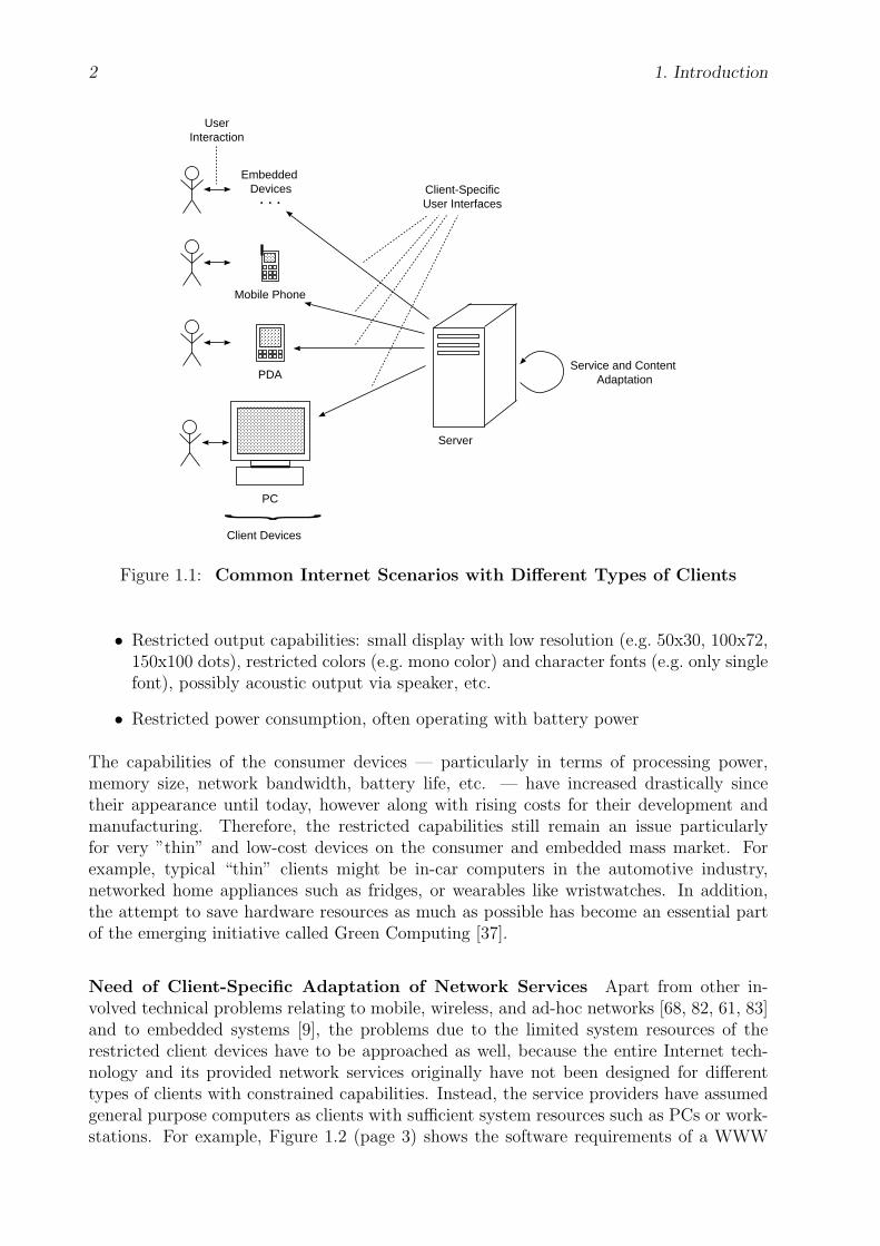
Traditionally, the access to Web content and other network services was limited to generalpurpose computers such as PCs or high-end workstations. In general, these are bound to afixed place and are supplied with the typical system resources, e.g., a powerful processor,sufficient memory and secondary storage, monitor, mouse, keyboard, etc. With the newconsumer devices, however, there has emerged a growing demand to access Web contentand other network services with any — possibly mobile, wireless, and embedded — device,as illustrated in Figure 1.1 (page 2). A very common use case might be surfing the WWWwith a mobile phone or an in-car computer.
Constrained System Resources Restricted consumer devices are often dedicated toa special purpose and therefore do not have the hardware and software capabilities asgeneral purpose computers have. The typical limitations of the first consumer devices canbe summarized as follows:
• Low processing power: e.g. 1-10 MIPS
• Small memory: e.g. 128-512 Kbytes RAM, 0.5-1 Mbytes ROM
• Network connection often wireless and intermittent with limited bandwidth (e.g. 9600bps or less), often no TCP/IP [69], high latency, etc.
• Restricted input capabilities: limited keyboard with a few input buttons, no mouse,possibly a touchscreen instead of a keyboard, possibly acoustic input via microphone,etc.
1
2 1. Introduction
...
Mobile Phone
PC
PDA
{Client Devices
Server
Embedded Devices
UserInteraction
Service and Content Adaptation
Client-SpecificUser Interfaces
Figure 1.1: Common Internet Scenarios with Different Types of Clients
• Restricted output capabilities: small display with low resolution (e.g. 50x30, 100x72,150x100 dots), restricted colors (e.g. mono color) and character fonts (e.g. only singlefont), possibly acoustic output via speaker, etc.
• Restricted power consumption, often operating with battery power
The capabilities of the consumer devices — particularly in terms of processing power,memory size, network bandwidth, battery life, etc. — have increased drastically sincetheir appearance until today, however along with rising costs for their development andmanufacturing. Therefore, the restricted capabilities still remain an issue particularlyfor very ”thin” and low-cost devices on the consumer and embedded mass market. Forexample, typical “thin” clients might be in-car computers in the automotive industry,networked home appliances such as fridges, or wearables like wristwatches. In addition,the attempt to save hardware resources as much as possible has become an essential partof the emerging initiative called Green Computing [37].
Need of Client-Specific Adaptation of Network Services Apart from other in-volved technical problems relating to mobile, wireless, and ad-hoc networks [68, 82, 61, 83]and to embedded systems [9], the problems due to the limited system resources of therestricted client devices have to be approached as well, because the entire Internet tech-nology and its provided network services originally have not been designed for differenttypes of clients with constrained capabilities. Instead, the service providers have assumedgeneral purpose computers as clients with sufficient system resources such as PCs or work-stations. For example, Figure 1.2 (page 3) shows the software requirements of a WWW

1.2. Client-Specific Service and Content Adaptation 3
client. Nowadays, a WWW client is supposed to process protocol and data formats like
HTTP
Interpreter
GUI
Networkcommunication
Native
{
{
{{
XML, CSS, JavaScript, Java Bytecode, Flash, MPEG, WMA, GIF, JPEG, PNG, PDF, etc.
Hardware
+
Software
Browser
HTML
TCP/IP
OS
CPU
Figure 1.2: Software Requirements of a WWW Client
HTTP [10], HTML [65] and other XML [16]-based formats, CSS [12], JavaScript [27], Javabytecode [42], PDF [5], and several graphics, audio, and multimedia formats like GIF [29],JPEG [39], PNG [1], MP3 [46], WMA [93], MPEG [47], and Flash [28] for images, sounds,movies, and animations. Clearly, a restricted consumer device hardly can manage thisvariety of quite complex data formats.
To make network services accessible to the restricted client devices, a client-server archi-tecture is required that adapts a requested network service to the particular hardwareand software capabilities of the client device. Adaptation of network services can be per-formed on all layers of the ISO/OSI [81] protocol stack. For example, on the applicationlayer mainly (user-)interactive network services are concerned. These are network serviceswhere the user of the client device is directly involved in the events of the network service.Here a so-called user agent runs on the client device which manages the communicationwith the server, makes the received server responses with the help of user interfaces visibleor audible on the client device, and provides facilities for the user to interact. The WWWis an example of an interactive network service. Here, the browser software, e.g., MicrosoftInternet Explorer or Mozilla Firefox, represents the user agent and displays the downloadedHTML documents on the client’s screen. The user can scroll within the downloaded HTMLdocument and follow hyperlinks via mouse clicks.
In addition to the client capabilities, the user of the client device should also be able toreport his or her preferences when requesting a particular interactive network service. Forexample, the user might set a certain language, turn the sound off/on, or deactivate thereception of images.
1.2 Client-Specific Service and Content Adaptation
In general, data like HTML documents, images, etc., are involved in interactive networkservices. These resources are widely called content. Service adaptation usually involvescontent adaptation, as well. A common example of content adaptation is the filtering ofHTML documents. Complex HTML markup elements, e.g., <TABLE>, <FRAME>, or imagesmight be replaced by simpler markup elements or alternative representations, or they mightbe stripped off. Another example is the conversion of related data formats, e.g.:
• HTML [65] (WWW [92]) ←→ WML [56] (WAP [54])
4 1. Introduction
• JPEG [39] ←→ GIF [29] ←→ PNG [1]
• WAV [47] −→ WMA [93], MP3 [46]
• color image ←→ gray scale image ←→ mono color image
• written text ←→ spoken language
The conversion of the communication protocols HTTP [10] (WWW)←→WSP [57] (WAP)is also an example of service adaptation.
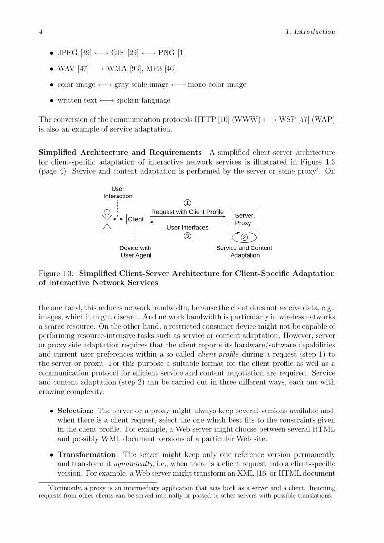
Simplified Architecture and Requirements A simplified client-server architecturefor client-specific adaptation of interactive network services is illustrated in Figure 1.3(page 4). Service and content adaptation is performed by the server or some proxy†. On
UserInteraction
Service and Content Adaptation
2
Client
Device with User Agent
Server,Proxy
Request with Client Profile
User Interfaces3
1
Figure 1.3: Simplified Client-Server Architecture for Client-Specific Adaptationof Interactive Network Services
the one hand, this reduces network bandwidth, because the client does not receive data, e.g.,images, which it might discard. And network bandwidth is particularly in wireless networksa scarce resource. On the other hand, a restricted consumer device might not be capable ofperforming resource-intensive tasks such as service or content adaptation. However, serveror proxy side adaptation requires that the client reports its hardware/software capabilitiesand current user preferences within a so-called client profile during a request (step 1) tothe server or proxy. For this purpose a suitable format for the client profile as well as acommunication protocol for efficient service and content negotiation are required. Serviceand content adaptation (step 2) can be carried out in three different ways, each one withgrowing complexity:
• Selection: The server or a proxy might always keep several versions available and,when there is a client request, select the one which best fits to the constraints givenin the client profile. For example, a Web server might choose between several HTMLand possibly WML document versions of a particular Web site.
• Transformation: The server might keep only one reference version permanentlyand transform it dynamically, i.e., when there is a client request, into a client-specificversion. For example, a Web server might transform an XML [16] or HTML document
†Commonly, a proxy is an intermediary application that acts both as a server and a client. Incomingrequests from other clients can be served internally or passed to other servers with possible translations.
1.3. Thesis Scope — Client-Specific Graphical User Interfaces 5
into a suitable WML document. The XML based tree transformation language XSLT[22] might be used for such transformations.
• Generation: Finally, the server might keep an abstract description of its offerednetwork service and content and generate dynamically a client-specific client-serversession with adapted content. This requires, among other things, a language fordescribing network services, user interfaces, and content abstractly. The client-serverarchitecture that is proposed in this thesis is based on the generative approach andwill be discussed in more detail later on.
The adapted content is then sent to the client (step 3). In an interactive network service,the user agent of the client device presents the received content as a user interface. Forexample, in the WWW the HTML markup language is used as the description formatfor the user interface, whereas the browser software renders the HTML document anddisplays it on the screen of the client device. Considering the different rendering anddisplay capabilities of the consumer devices, the description format for the user interfacesis a main issue. For example, the WAP Forum [54] has developed the less powerful markuplanguage WML [56] for the wireless consumer devices.
In addition, the presentation of user interfaces on small displays also leads to major chal-lenges in the fields of layout design and therefore might involve ergonomic factors. Forexample, one important question might be, how information can be rendered ergonomi-cally on a small display to make it as much readable as possible. On the other hand, itmight also be important, how visual information and its inherent logical structure, which isfor example given by an HTML document, can be transformed best into spoken language.
1.3 Thesis Scope — Client-Specific Graphical User
Interfaces
The topic of client-specific network service and content adaptation is very large and canbe discussed at all levels of the ISO/OSI [81] reference model with all kinds of differentcontent formats and client devices.
Therefore, this thesis mainly focuses on interactive network services on the applicationlayer. Particularly, it deals with the generation of client-specific client-server sessions andgraphical user interfaces (GUIs) from abstract user interface descriptions. Because of thelarge diversity of today’s and future consumer devices, the proposed thesis mainly addressesdevices with a graphic display for the output and with a keyboard and optionally a mousefor the input. However, other devices, e.g., devices with acoustic input and output, aretaken into consideration as far as to enable enhancements towards these devices withoutsubstantial changes in the proposed ideas of this thesis.
The conversion of related multimedia, image, or other content formats and the conversionof written text or graphical user interfaces into speech for acoustic output are not coveredhere. Below the application layer a reliable network transport service, like TCP/IP [69] inthe Internet, is assumed. How such a transport service is established in mobile, wireless,and ad-hoc networks is not covered here, either.
Finally, the proposed thesis only deals with the technical aspects regarding the generationof client-specific client-server sessions and graphical user interfaces, but it does not address
6 1. Introduction
layout-related or other ergonomic issues to avoid unnecessary restrictions. Rather, it pro-poses a technical platform that leaves service and content providers as much flexibility andalso responsibility in layout-related and other ergonomic decisions as possible.
1.4 Related Work — Overview
A lot of working groups, many of them from the industrial sector, have early addressed thetopic of providing interactive content and services for restricted client devices. Here, onlythe most important activities are introduced briefly:
World Wide Web Consortium (W3C) The World Wide Web Consortium (W3C)[92] has several working groups that deal with the description format for documents anduser interfaces in the World Wide Web (WWW):
XHTML Basic The modularization of XHTML, XHTML 1.1 [6], decomposesXHTML 1.0 [60], which is the successor of HTML 4.01 [65], into functional subsets calledmodules. The module XHTML Basic [8] is specifically designed for Web clients such as mo-bile phones, PDAs, pagers, set-top boxes, etc., that do not support the full set of XHTMLfeatures. Mainly, XHTML Basic contains markup elements for basic text (including head-ings, paragraphs, and lists), hyperlinks and links to related documents, basic forms, basictables, images, and meta information. However, it does not support style sheets, scripting,and frames.
XML, CSS, XSL The XML [16] working group of W3C pursues a separation ofcontent and layout. In contrast to HTML documents which contain both content andlayout information, the XML documents only contain logically structured content. Asthe XML elements have no intrinsic presentation semantics, layout has to be provided byadditional style sheets, e.g., CSS [12] or XSL [2].
A CSS style sheet document is sent together with the XML document to the client device.On the client device a rendering engine, which understands CSS, formats and displays theXML document according to the style directives given in the CSS style sheet. As CSS is aquite powerful and complex style sheet language, a subset of CSS has been defined, calledCSS Mobile Profile [95], which is tailored to the needs and constraints of mobile devices.
XSL consists of the tree transformation language XSLT [22] and a set of formatting objectsand properties XSL-FO [2]. The XML document is first transformed with a given XSLTstyle sheet document into the resulting document. The client then renders and displaysthe resulting document. Note that the resulting document does not necessarily need tocomply to XSL-FO. It may as well have any other XML-like format that is understoodby the client. The tree transformation can be performed on the server or on the clientside. If it is performed on the server side, then only the resulting document is sent tothe client. Otherwise, both the XML and the XSLT style sheet documents are sent tothe client. However, a resource-constrained client device might not be capable to performsuch a resource-intensive task such as tree transformation. With the use of XSL an existingXML document might serve as a reference which is transformed dynamically to other XMLdocuments that suit the client capabilities.

1.4. Related Work — Overview 7
XForms The XForms [24] working group of W3C deals with the next generation ofWeb forms which can be used with a wide variety of platforms including desktop computers,hand-helds, information appliances, etc. The XML-based language XForms describes userinterfaces declaratively, i.e., not operationally, and on a quite high, i.e., abstract, level.
Composite Capabilities/Preferences Profiles (CC/PP) The CC/PP workinggroup [90] of W3C has developed the Composite Capabilities/Preferences Profiles (CC/PP)framework [66] [49]. It consists mainly of an RDF [44] and XML [16] based format for de-scribing the hardware and software capabilities of the client device and its user preferences,the CC/PP Profile [40], and an exchange protocol for content negotiation between clientand server, the CC/PP Exchange Protocol [53]. The client sends its CC/PP profile withinthe request to the service provider. The service provider can use this information to cus-tomize its provided service or content, before it replies to the client. The vocabulary of theCC/PP profile is designed to be broadly compatible with the UAProf specification [59] fromthe WAP Forum [54]. It includes information about the hardware platform (e.g. vendor,model, class of device, screen size, etc.), the software platform (e.g. operating system, levelof HTML, CSS, JavaScript, Java, and WAP support, etc.), and about an individual ap-plication (e.g. browser, etc.) of the client device. The CC/PP exchange protocol is basedon the HTTP Extension Framework [48]. Note that HTTP is the assumed underlyingprotocol but the CC/PP framework might also be transportable over other protocols.
In the meantime the CC/PP working group has closed and its work moved to the DeviceIndependence working group [91].
Wireless Application Protocol Forum (WAP) The Wireless Application ProtocolForum (WAP) [54] has specified a network protocol stack and an application frameworkfor wireless consumer devices. Among others, they have developed WSP [57], WML [56],and WMLScript [58] which are, roughly speaking, the counterparts of HTTP, HTML, andJavaScript in the WWW respectively. In addition, the WAP Forum has also developed acore vocabulary, UAProf [59], for mobile devices, which complies with the CC/PP profileformat of W3C. UAProf describes the hardware and software characteristics of the clientdevice as well as the type of network to which the client device is connected. It definesattributes for the components “HardwarePlatform”, “SoftwarePlatform”, “NetworkChar-acteristics”, “BrowserUA”, “WapCharacteristics”, and “PushCharacteristics”.
In the meantime, the WAP Forum has consolidated into the Open Mobile Alliance (OMA)[55] and no longer exists as an independent organization. However, the specification workfrom WAP continues within OMA.
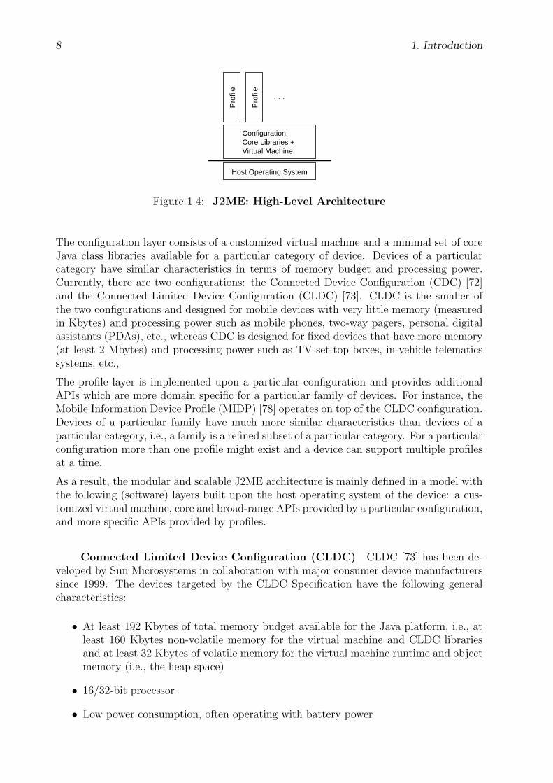
Java 2 Platform, Micro Edition (J2ME) Sun Microsystems has grouped its Javatechnologies [77] into three editions with each aiming at a particular area in computingindustry: the Java 2 Enterprise Edition (J2EE) for enterprises, the Java 2 Standard Edition(J2SE) for the desktop computer market, and the Java 2 Micro Edition (J2ME) [74] for theconsumer and embedded device market. The high-level architecture of J2ME is illustratedby figure 1.4 (page 8).
For the host operating system only a minimal operating system is assumed that managesthe underlying hardware. Support for separate address spaces or processes, guaranteesabout real-time scheduling or latency behavior, etc., are not required.
8 1. Introduction
Host Operating System
Configuration:Core Libraries +Virtual Machine
Pro
file
Pro
file
...
Figure 1.4: J2ME: High-Level Architecture
The configuration layer consists of a customized virtual machine and a minimal set of coreJava class libraries available for a particular category of device. Devices of a particularcategory have similar characteristics in terms of memory budget and processing power.Currently, there are two configurations: the Connected Device Configuration (CDC) [72]and the Connected Limited Device Configuration (CLDC) [73]. CLDC is the smaller ofthe two configurations and designed for mobile devices with very little memory (measuredin Kbytes) and processing power such as mobile phones, two-way pagers, personal digitalassistants (PDAs), etc., whereas CDC is designed for fixed devices that have more memory(at least 2 Mbytes) and processing power such as TV set-top boxes, in-vehicle telematicssystems, etc.,
The profile layer is implemented upon a particular configuration and provides additionalAPIs which are more domain specific for a particular family of devices. For instance, theMobile Information Device Profile (MIDP) [78] operates on top of the CLDC configuration.Devices of a particular family have much more similar characteristics than devices of aparticular category, i.e., a family is a refined subset of a particular category. For a particularconfiguration more than one profile might exist and a device can support multiple profilesat a time.
As a result, the modular and scalable J2ME architecture is mainly defined in a model withthe following (software) layers built upon the host operating system of the device: a cus-tomized virtual machine, core and broad-range APIs provided by a particular configuration,and more specific APIs provided by profiles.
Connected Limited Device Configuration (CLDC) CLDC [73] has been de-veloped by Sun Microsystems in collaboration with major consumer device manufacturerssince 1999. The devices targeted by the CLDC Specification have the following generalcharacteristics:
• At least 192 Kbytes of total memory budget available for the Java platform, i.e., atleast 160 Kbytes non-volatile memory for the virtual machine and CLDC librariesand at least 32 Kbytes of volatile memory for the virtual machine runtime and objectmemory (i.e., the heap space)
• 16/32-bit processor
• Low power consumption, often operating with battery power
1.4. Related Work — Overview 9
• Network connection often wireless, intermittent, and with limited bandwidth
The underlying Java virtual machine is the K Virtual Machine (KVM) [79]. The KVMis derived from the standard Java Virtual Machine (JVM), but designed from the groundup for small-memory, limited-resource, and network-connected devices. The “K” in KVMstands for “kilo”, i.e., memory budget is measured in kilobytes. The KVM includes theexecution of byte code, automatic garbage collection, and multi-threading. On the Javalanguage and virtual machine level all central aspects are maintained with the followingrestrictions:
• No finalization of objects (i.e., Object.finalize()), no asynchronous exceptions, nouser-defined class loaders, no thread groups and daemon threads, and no Java NativeInterface (JNI)
• Limited set of error classes
CLDC contains classes that are identical or a subset of the corresponding standard J2SEclasses, e.g., from the packages java.lang.*, java.util.*, java.io.*, and it containsadditional classes outside J2SE which are specific to CLDC and inside the package javax.-microedition.*.
CLDC does not cover application management (installation, launching, deletion) and userinterface functionality (user interface components and event handling). These featureshave to be addressed by profiles implemented on top of the CLDC.
Mobile Information Device Profile (MIDP) The MIDP is designed for mobilephones, PDAs, and similar devices. Mainly it provides Java APIs for user interfaces,network connectivity, local data storage, sound, timers, and application management. Thedevices targeted by the MIDP Specification should have the following minimum hardwarecharacteristics:
• Visual Output: screen size: 96x54, display depth: 1 bit, pixel shape (aspect ratio):approximately 1:1
• Input: one-handed keyboard or two-handed keyboard or touch screen
• Memory:
– 256 Kbytes of non-volatile memory for MIDP implementation, beyond what’srequired for CLDC.
– 8 Kbytes of non-volatile memory for application-created persistent data
– 128 Kbytes of volatile memory for the Java runtime (e.g. Java heap)
• Networking: two-way, wireless, possibly intermittent, with limited bandwidth
• Sound ability
Other Some other activities like [11], [19], [25], [94], [84], [13], [23], etc., concentratemore on the layout-related and ergonomic aspects of content adaptation and presentation,which is performed on the server/proxy-side. For the description of user interfaces theyrely on existing XML-based formats like HTML [65] and WML [56].

10 1. Introduction
1.5 Summary of the Chapters
This section gives a summary for each chapter to come:
2 Proposed Client-Server Architecture — Overview This chapter gives an over-view of the proposed client-server architecture that enables the generation of client-specificuser interfaces for restricted client devices within the context of interactive network serviceson the application layer. It motivates the main ideas but does not go too much into details.
First, the main components of interactive network services are listed. Then, it is discussedwhich user interface description format is most suitable for client devices with differentand restricted capabilities. In particular, the requirements of scalability, compactness, andfunctionality are addressed and it is discussed whether the description format should bedeclarative or operational. Thereby, different levels of abstraction are considered. As aresult, a new virtual machine, called the Client Virtual Machine (CVM), is introducedthat runs on the client device and serves as an interpreter for the new description format.On the server side a framework is presented where client-specific user interfaces with thenew description format are generated and sent as CVM packets to the requesting client.For the client-server communication a simple application protocol, called the CVM packettransfer protocol (CPTP), is introduced briefly.
Reading this chapter is sufficient to get the basic idea of this thesis. The next chaptersdiscuss the involved components of the proposed client-server architecture in detail.
3 Client Virtual Machine (CVM) This chapter specifies in detail the CVM andserves as a reference for any CVM implementor. The specification focuses mainly onthe behavior and special characteristics of its modules and functional units by avoidingunnecessary restrictions that are implementation specific. This chapter specifies also theCVM profile and the CVM packet format. The CVM profile format is used by the CVMwhen it reports its capabilities and user preferences to the CVM packet server duringa request. The CVM packet format is the new user interface description format andrepresents the binary executable format for the CVM. At the end of this chapter the maindifferences between the CVM and the JVM/KVM virtual machines from Sun Microsystemsare outlined.
4 CVM Packet Transfer Protocol (CPTP) This chapter specifies in detail theCPTP protocol which manages the client-server communication between the CVM and theCVM packet server. The CPTP protocol runs on top of the transport layer and is a very“thin” counterpart to the HTTP protocol which is used in the World Wide Web. At theend of this chapter an exemplary CPTP session is demonstrated.
5 CVM Packet Server (CVMPS) This chapter specifies an exemplary server-sidearchitecture for the CVM packet server. The CVM packet server processes the clientrequests and generates session instances and CVM packets that are optimized for theindividual client capabilities. The exemplary CVM packet server consists of the followingcomponents:
1.5. Summary of the Chapters 11
• An abstract user interface description language (AUI) has been developed to specifyinteractive network services on the application layer. It provides language constructsto specify the client-side user interface components as well as language constructs toembed code for state-dependent actions that are executed on the client and serverside. Client-side actions are specified in CVM assembler whereas server-side actionscan be specified in any common programming language.
• The session manager processes all incoming client messages and stores the data thatare involved during the client-server sessions.
• The service generator generates the client-specific service instance from a given AUIdescription and CVM profile.
• The CVM packet generator generates customized CVM packets from a given AUIdescription and CVM profile. These CVM packets are called CVM user interfaces.A CVM user interface may contain all parts of the requested AUI page or only asmaller subset.
6 Conclusions This chapter summarizes the main results and outlines perspectivesfor future work.
A Notations This appendix contains a description of the used notations.
B CVM Assembler (CVMA) This appendix specifies the CVM Assembler. Itssyntax is used for the generated code samples throughout this thesis.
C CVMUI Library (CVMUI Lib) This appendix contains an exemplary imple-mentation of the CVMUI library. The CVMUI library contains constant and functiondefinitions that are imported by CVMUI programs.
D CVM Packet Server: Example This appendix contains the C and CVMA sourcecode of the generated service instance and the CVM packets of an AUI description for anexemplary network service.
Chapter 2
Proposed Client-Server Architecture— Overview
On the client side, different levels of abstraction for describing graphical user interfacesare discussed and a new description format for it is presented. This format takes intoaccount from scratch the limited display capabilities of the restricted consumer devicesand thus enables scalability, i.e., “thinner” client devices may receive simpler user interfacedescriptions. A new virtual machine, called Client Virtual Machine (CVM), runs on theclient device and serves as the user agent. It interprets and displays the received userinterface descriptions.
On the server side, client-specific user interfaces and client-server sessions are generatedfrom abstract user interface descriptions.
The communication between the client and the server is managed by a new and simpleapplication protocol, called CVM packet transfer protocol (CPTP).
As already said in the introduction of this thesis, the proposed architecture for the genera-tion of client-specific user interfaces mainly deals with the technical, but not layout relatedor other ergonomic aspects. As the basic ideas of the proposed client-server architectureare independent of any particular layout design, the service providers gain as much flex-ibility and also responsibility in layout-related and other ergonomic decisions as possiblewhen creating user interfaces for restricted clients with limited capabilities.
2.1 Main Components of Interactive Network
Services
First, the essential components that are necessary to implement interactive network serviceson the application layer will be summarized:
The server contains the control logic of the network service, manages the involved content,and supplies the client with user interfaces to be displayed. The control logic definesthe course of the network service. A network service might consist of several phases.Between the phases client-server communication takes place to exchange data. In general,the control logic can be implemented by an (unrestricted) state machine. The involvedcontent might be any data, e.g., text documents, forms, images, databases, etc., and ispacked into user interfaces. The main task of a client is — apart from sending its request
12

2.2. Client Side 13
to a server for a particular network service — to display the received user interfaces on theclient device. Therefore it needs a runtime environment or interpreter which is frequentlyalso called browser or user agent. At last, a protocol is required for the client-servercommunication on the application layer.
The WWW is an example of an interactive network service on the application layer. How-ever, in the traditional WWW the above components are not clearly separated: On theone hand, HTML [65] — possibly enriched with JavaScript [27] and Java [36] code — isused as the user interface description format on both the server and the client side. Onthe other hand, parts of the control logic, for instance the handling of status and errormessages, are specified in the HTTP [10] communication protocol, instead.
2.2 Client Side
On the client side mainly a user interface description format is needed which suits thedifferent capabilities and limitations of the networked clients and thus enables scalability.
2.2.1 User Interface Description Format
In general, a graphical user interface consists of several user interface components, whereeach user interface component is characterized mainly by its graphic appearance and eventsemantics. The event semantics is usually defined by an event table which specifies foreach event type, e.g., a mouse click, a sequence of actions to be executed after the user hastriggered an event of that type. However, some components of a user interface might nothave any event semantics, e.g., a paragraph of simple text or an illustrative image. Thesenon-interactive components are mainly used for informational or stylistic purposes. Forreasons of generality they are referred to in this thesis as (non-interactive) user interfacecomponents as well.
Requirements The user interface description format for networked clients with differentand restricted capabilities must meet the following requirements:
1. Scalability: The user interface description format must be as general and scalableas to be displayable by current and future client devices with different capabilities,especially by small and restricted consumer and embedded devices. Ideally, its ap-pliance should also be suitable for general purpose computers with sufficient systemresources such as PCs or workstations.
2. Compactness: The user interface description format must allow compact encodingsof user interfaces to reduce network bandwidth during transport from the server tothe client.
3. Functionality: The user interface description format should provide equal function-ality and be as powerful as the current technologies that are used in the Internetnowadays such as HTML [65], JavaScript [27], and — to some extent — Java [36],because otherwise additional technologies are needed for more complicated and dy-namic tasks. This is the case with HTML which often includes JavaScript or Javacode for dynamic tasks.

14 2. Proposed Client-Server Architecture — Overview
2.2.1.1 Compactness vs. Scalability
To meet the requirements of scalability and compactness, a compromise must be foundbetween different levels of abstraction which are illustrated in figure 2.1 (page 14). The
Pixel-Bitmap
HTML: e.g. <UL>, <LI>, <A>,<TABLE>, <FORM>, <INPUT>,<FRAME>, etc.
Elementary Graphic Shapes: e.g. line, circle, rectangle, etc.
Level of Abstraction
Higher Level:Logical Description,
Compactness,Client-Side Rendering Efforts
Lower Level:Layout-Related Description,
Scalability,Server-Side Administration Efforts
Figure 2.1: Different Levels of Abstraction for User Interface Components
more abstract the user interface components are, the more compact the user interfacedescription becomes. But then less scalability can be achieved.
The different levels of abstraction will be discussed in more detail with the help of anexample of a simple user interface that is shown in figure 2.2 (page 14). This user interface
x
y
Screen
80
40
0
0 50 100
A hyperlink: http://www.in.tum.de
Here a list with 2 items:
Second itemFirst item
Finally a button: Click me
An example user interface
Cursor
Figure 2.2: Simple User Interface Example
example begins with a title on the top. Then an unnumbered list with two list itemsfollows. The next line represents a hyperlink to a WWW site at the given URL [26]. Thelast line begins with some text and finishes with a button. The current cursor positionis indicated here by a narrow horizontal line. It depends on the peripherals of the clientdevice how the user can control the cursor. As most consumer devices have limited inputcapabilities, some kind of arrow keys of the limited keyboard must be used for this taskinstead of a mouse which is usually only available on general purpose computers such asPCs or workstations. Apart from the cursor this user interface contains two interactivecomponents: the hyperlink and the button. The user can activate such an interactiveobject by first moving the cursor into the geometric region of the object and then pressing
2.2. Client Side 15
some kind of Enter key on the keyboard. The activation of the hyperlink results in anew client request for the WWW site at the explicitly given URL. After the button ispressed, any actions can be performed and are not specified here in more detail. In thefollowing discussion, this user interface will be described with respect to different levels ofabstraction.
High-Level Components A high-level user interface component does not predefine aspecific layout presentation. Instead, the user agent which displays this user interfacecomponent can choose a particular layout presentation. The only formatting constraint isthat its appearance reflects to the user intuitively what kind of user interface component itis. For example, a button should look like a button. In addition, a high-level user interfacecomponent may be of any complexity and might consist of several sub-components. Forexample, a list usually consists of several list items, a table usually consists of several rowswhich in turn consist of several columns each, or a form usually consists of several inputfields, buttons, etc. Typically, the default event semantics of a high-level user interfacecomponent is predefined implicitly without an explicit event table.
The markup language HTML [65] is an example of a high-level language for describinguser interfaces because it has several high-level markup elements such as <UL>, <LI>, <A>,<TABLE>, <FORM>, <INPUT>, <FRAME>, etc. For example, an unnumbered list can be describedin HTML with the markup element <UL>. Its list items are described each with the markupelement <LI> and listed as children inside the parental <UL> element. The <A> elementis used for hyperlinks. An input form is expressed by the <FORM> element and its sub-components, called controls, can each be specified with the <INPUT> element. The typeattribute of the <INPUT> element then specifies the control type, which might be a button,a text input field, etc. A button, for example, is expressed with the type attribute value"button". In general, the default event semantics of an interactive HTML element isimplicitly predefined. Additional event semantics must be specified with the help of ascripting language such as JavaScript [27]. The corresponding scripting code is embeddedinto the HTML document. For example, the scripting code for the actions on a buttonclick can be provided by the value of the onclick attribute of the corresponding <INPUT>element. The rendering of a high-level markup element into a particular layout presentationon the display of the client device is performed by the browser which runs on the clientdevice and interprets the downloaded HTML document. Therefore, the browser determinesthe graphic appearance of a high-level markup element. In the course of time, however,similar representations for most markup elements have emerged for the common browserslike the Microsoft Internet Explorer or Mozilla Firefox. The above user interface can bespecified in HTML as follows:
<HTML><HEAD><TITLE>An example user interface</TITLE><META http-equiv="Content-Script-Type" content="text/javascript"/>
</HEAD><BODY><FONT face="Helvetica" size="3" color="black"><FONT size="+1"><I><STRONG>An example user interface</STRONG></I></FONT><P>Here a list with 2 items:
<UL><LI>First item
16 2. Proposed Client-Server Architecture — Overview
<LI>Second item</UL><A href="http://www.in.tum.de">A hyperlink: http://www.in.tum.de</A><FORM action="http://somesite.com/handle" method="post">Finally a button:<INPUT type="button" value="Click me"
onclick="/* Here comes the JavaScript code */"/></FORM>
</P></FONT>
</BODY></HTML>
The benefit of a high-level description language like HTML is that its language constructsallow quite compact descriptions of user interfaces, which is good to keep network band-width low. But on the other side, the client-side rendering efforts rise, because the clienthas to interpret these abstract user interface elements and perform the formatting into aparticular layout presentation. Because of the complexity of some user interface compo-nents, this task might impose a lot of effort for the client. Therefore, a resource-limitedclient can hardly process complex user interface elements. The only way for a resource-limited client then is to omit user interface components with higher complexity. In termsof HTML, only a subset of its markup elements, which excludes elements like <TABLE>,<FORM>, <INPUT>, <FRAME>, etc., can be processed by a resource-limited client. Contentadaptation then would rather become a matter of content filtering. As a result, becauseof its lack of scalability, a high-level description language for user interfaces like HTML isnot suitable for limited client devices.
Pixel Bitmap Image If user interfaces are described on a lower level, more scalabil-ity and flexibility can be achieved for their adaptation. The lowest level for describinga particular user interface component might be a pure pixel bitmap that represents theimage of its graphic appearance and an explicit event table that defines the event seman-tics. Then, the whole user interface description is an image whereas each user interfacecomponent occupies a particular geometric area inside the image. The event table definesthe corresponding event semantics for each geometric area of the image that belongs toan interactive user interface component. Then, the above user interface can be describedexemplarily in a C-like syntax [20] as follows:
char pixel_bitmap[] ={/* Byte array which encodes the image of the user interface
as a pixel bitmap. */}
void event_table(){if ( /* Arrow left key pressed ? */ ){ /* Move cursor left. */ }
else if ( /* Arrow right key pressed ? */ ){ /* Move cursor right. */ }
else if ( /* Arrow up key pressed ? */ )

2.2. Client Side 17
{ /* Move cursor up. */ }else if ( /* Arrow down key pressed ? */ ){ /* Move cursor down. */ }
else if ( /* Enter key pressed ? */ ){if ( /* Current cursor position inside of rectangle
[(5, 50), (90, 60)] ? */ ){/* Action code for the hyperlink: a new WWW request
with the URL "http://www.in.tum.de". */}
else if ( /* Current cursor position inside of rectangle[(50, 65), (80, 75)] ? */)
{ /* Action code for the button: application specific ... */ }}
}
For reasons of brevity and clearness this description concentrates only on the essential parts.In addition, some sections are expressed informally within comments. The user interfacedescription consists of two main parts: First comes the byte array (pixel bitmap[]) thatencodes the image of the user interface as a pixel bitmap. Next comes the event table(event table()). The event table defines the corresponding actions for each event type,e.g., Enter key pressed, and the xy coordinates of the current cursor position. If the cursorposition falls inside the geometric region of an interactive element while the user triggersan event of a particular type, then the corresponding actions are executed. Here, thegeometric region of the hyperlink is defined by the rectangle with the (x, y) corners (5,50) and (90, 60), and the geometric region of the button is specified by the rectangle withthe corners (50, 65) and (80, 75). The event table and its actions must be encoded in alanguage format that the client device understands.
The main benefit of this approach is that the client does not need to render the graphicdescription of the user interface into a particular layout presentation because it is alreadyencoded as a pure pixel bitmap image.
However, this approach also results in serious problems: First, the transport of bitmapimages from the server to the client wastes too much network bandwidth, because bitmapimages are quite huge even for small displays. If each pixel point is specified using the 24-bitRGB color model [70], then the whole size of the user interface description, which consistsof the pixel bitmap and the event table, exceeds 100x80x3 = 24000 bytes. In comparison,the equivalent HTML description of the above user interface only requires approximately700 bytes. In spite of the rapid developments in the area of wired and wireless networktechnology to provide more bandwidth, e.g., UMTS [87], network bandwidth might alwaysbe a limited resource. Compact image encoding formats like GIF [29], JPEG [39], etc.,might help to reduce bandwidth requirements but not sufficiently. In addition, the clientdevice then would have to perform some processing to decode the image.
Another problem is that user interaction is very hard to implement this way, because auser interface component might change its appearance when the user interacts with it. Forexample, the shading of a button might change when it is pressed or the color of a hyperlinkmight change after it has been visited by the user. A more complex example might be aneditable text field which updates synchronously the contents of its text field while being
18 2. Proposed Client-Server Architecture — Overview
edited by the user. In addition, the cursor — which is also part of the image — changesits position when the user presses one of the arrow keys. Whenever the user interfacecomponents change their appearance, the client — if we assume that it does not performany rendering of the user interface — has to send an appropriate notification message tothe server and wait for an updated image that reflects the new state of the user interface.The server, on the other side, has to keep track of the current state of the client-side userinterface and send the updated image to the client after each received notification message.Thus, each user interaction leads to additional network traffic and might cause a networkoverload. In addition, the server has to do a lot of administration tasks. After each userinteraction, it has to process a notification message and deliver the image that reflects thecurrent state of the user interface.
It becomes clear that this approach cannot be implemented practically. This approachreduces the rendering efforts of the client to a minimum, but the bandwidth requirementsand server-side administration efforts are immense. Therefore, more capabilities of theclient are required to decrease the bandwidth requirements and server-side administrationefforts.
Elementary Graphic Shapes The previously discussed approaches are extreme in na-ture. The first one describes a user interface from a very abstract and logical view withouta strict relation to a particular layout presentation. The second approach defines a userinterface by a pixel bitmap image and an explicitly defined, coordinate-based event table.Apart from the pixel point — which is the most elementary and unsplittable graphic objectat all — the second approach does not assume any other or even higher-level componentsto form the graphic appearance of a user interface.
As a result, a compromise between these two extreme approaches might be elementaryuser interface components that are low level enough to serve as building blocks for morecomplicated user interface objects, but still allow compact descriptions of user interfaces.Besides text, the building blocks are elementary graphic shapes that occur frequently inuser interfaces components such as lines, circles, rectangles, etc.
For example, the above user interface can be described with these elementary graphicshapes in an XML-like syntax [16] as follows:
<paint fontName="Helvetica" fontStyle="normal" fontSize="14pt" color="black"><text x="5" y="12" fontStyle="bold italic" fontSize="17pt"
string="An example user interface"/><text x="5" y="25" string="Here a list with 2 items:"/><circle x="10" y="30" radius="3" fill="true"/><text x="20" y="35" string="First item"/><circle x="10" y="38" radius="3" fill="true"/><text x="20" y="43" string="Second item"/><text x="5" y="55" string="A hyperlink: http://www.in.tum.de"/><line x1="5" y1="57" x2="85" y2="57"/><text x="5" y="72" string="Finally a button:"/><rect x1="50" y1="65" x2="80" y2="75"/><text x="55" y="72" string="Click me"/>
</paint><eventTable>
<!-- entry for the hyperlink: -->
2.2. Client Side 19
<entry x1="5" y1="50" x2="90" y2="60" type="Enter key pressed" action="..."/><!-- entry for the button: --><entry x1="50" y1="65" x2="80" y2="75" type="Enter key pressed" action="..."/>
</eventTable>
The names of the markup elements and attributes should be self-explanatory. This userinterface description consists of two main sections. The first section is enclosed by themarkup element <paint> and defines the visual appearance of the graphical user interface.The second section is limited by the markup element <eventTable> and contains the eventtable. By default, each child element inherits the attribute values of its parent element, ifit does not overwrite them. For example, the first occurring <text> element in the aboveuser interface description inherits the fontName attribute of the parental <paint> element,whereas it overwrites the parental fontStyle and fontSize attributes. The child elementsof the <paint> element represent elementary graphic shapes which serve as building blocks.For example, the <text> element prints out the string that is given by its string attributeon the display at the coordinate position that is given by its x and y attributes. The<line> element draws a line that starts at the coordinate position given by the x1 and y1
attribute values and ends at the position given by the x2 and y2 attribute values. Each<entry> element defines the corresponding actions for a particular user event. If the typeof the user event matches the value of the type attribute and the current cursor positionfalls into the rectangular area that is limited by the corners (x1, y1) and (x2, y2), then theclient device executes the sequence of actions given by the value of the action attribute.For this the sequence of actions must be encoded in a language that the client understands.
In the following discussion, the building block idea is demonstrated by comparing particularsections of this user interface description with the equivalent sections of the correspondingHTML description: The lines
<circle x="10" y="30" radius="3" fill="true"/><text x="20" y="35" string="First item"/><circle x="10" y="38" radius="3" fill="true"/><text x="20" y="43" string="Second item"/>
build the unordered list which is expressed in HTML with
<UL><LI>First item<LI>Second item
</UL>.
The lines
<text x="5" y="55" string="A hyperlink: http://www.in.tum.de"/><line x1="5" y1="57" x2="85" y2="57"/>
...<!-- entry for the hyperlink: -->
<entry x1="5" y1="50" x2="90" y2="60" type="Enter key pressed"action="..."/>
build the hyperlink which is expressed in HTML with

20 2. Proposed Client-Server Architecture — Overview
<A href="http://www.in.tum.de">A hyperlink: http://www.in.tum.de</A>.
The lines
<rect x1="50" y1="65" x2="80" y2="75"/><text x="55" y="72" string="Click me"/>
...<!-- entry for the button: -->
<entry x1="50" y1="65" x2="80" y2="75"type="Enter key pressed" action="..."/>
build the button which is expressed in HTML with
<FORM action="http://somesite.com/handle" method="post">...
<INPUT type="button" value="Click me"onclick="/* Here comes the JavaScript code */"/>
</FORM>.
In order to relieve the client from the task of performing layout computations, this userinterface description explicitly contains the absolute xy coordinate positions for each userinterface component. A mixture of relative and absolute xy coordinates might also beused. The formatting and assignment of the xy coordinates is performed by the server.As a result, the client can draw instantly the elementary graphic shapes without largerendering efforts.
Here, a pixel point is used as the measuring unit for the xy coordinates. However, asthe dimension of a pixel point generally varies between different screen types of the clientdevices, an absolute and platform-independent measuring unit such as the Big Point orshortly Point (pt) might be used as well. The size of a Point equals to 1/72 inch and iswidely used as the typographic unit in computer industry.
As this user interface description is only a little larger than the equivalent HTML descrip-tion, this approach satisfies the two requirements of scalability and compactness. However,this user interface description does not specify how the cursor is controlled. In addition,this approach does not address the issue, which programming language might be used toencode the actions of the interactive components, either. These topics are discussed next.
2.2.1.2 Declarative vs. Operational
The third requirement of functionality leads to the question whether the user interfacedescription should be declarative† or operational. Declarative means that the user interfaceis described without control-flow language constructs. In combination with high-level userinterface components with default event semantics quite compact user interface descriptionscan be achieved. HTML is an example of a declarative language. However, a declarativelanguage reaches its limitations, when dynamic aspects of the user interface need to bespecified explicitly such as individual and application-specific event semantics of particularinteractive user interface components, because it is very difficult to describe actions, whichare operational by nature, in a declarative way. HTML, therefore, has to include code
†The term descriptive is occasionally used as a synonym for the term declarative.
2.2. Client Side 21
written in another operational language, e.g., JavaScript [27], for these tasks. To avoidthe dependence on another operational language the user interface must be described inan operational manner. Besides, an operational language can be interpreted by the clientmore directly and easier than a declarative language. Using this approach, a particular userinterface description is a program for a virtual user interface machine, which is here calledthe Client Virtual Machine (CVM). Then, the above user interface might be describedoperationally in a C- and assembler-like syntax exemplarily as follows:
/* application specific variable declarations */
/* xy position and length of cursor */int xPos = 0, yPos = 0, lenCursor = 10;
/* state of the hyperlink */boolean isVisited = false;
/* state of the button */boolean isCurrentlyPressed = false;
/* paint procedures */
/* entry point for execution */main:call paintUserInterfacecall paintCursorabort
/* paint procedure for the user interface */paintUserInterface:setcolor blacksetfont Helvetica, bold italic, 17 /* name, style, size */text 5, 12, "An example user interface" /* x, y, string */setfont Helvetica, normal, 14text 5, 25, "Here a list with 2 items:"circlefill 10, 30, 3 /* x, y, radius */text 20, 35, "First item"circlefill 10, 38, 3text 20, 43, "Second item"call paintHyperlinktext 5, 72, "Finally a button:"call paintButtonret
/* paint procedure for the hyperlink */paintHyperlink:if (isVisited == false)
{ setcolor blue }else
{ setcolor red }text 5, 55, "A hyperlink: http://www.in.tum.de"

22 2. Proposed Client-Server Architecture — Overview
line 5, 57, 85, 57 /* x1, y1, x2, y2 */setcolor blackret
/* paint procedure for the button */paintButton:if (isCurrentlyPressed == false){ setcolor green }
else{ setcolor red }
rectfill 50, 65, 80, 75 /* x1, y1, x2, y2 */setcolor blackrect 50, 65, 80, 75 /* x1, y1, x2, y2 */text 55, 72, "Click me"ret
/* paint procedure for the cursor */paintCursor:line xPos, yPos, xPos + lenCursor, yPosret
/* event semantics */
/* event attributes */int deviceCode, eventCode, eventPars[];
/* global event handling procedure */eventTable:if (deviceCode == KEYBOARD){if (eventCode == PRESSED)
{/* eventPars[0] contains the key code */if (eventPars[0] == LEFT_KEY && xPos > 0){xPos = xPos - 1call paintUserInterfacecall paintCursor}
else if (eventPars[0] == RIGHT_KEY && xPos < XMAX){xPos = xPos + 1call paintUserInterfacecall paintCursor}
else if (eventPars[0] == UP_KEY && yPos > 0){yPos = yPos - 1call paintUserInterfacecall paintCursor
2.2. Client Side 23
}else if (eventPars[0] == DOWN_KEY && yPos < YMAX)
{yPos = yPos + 1call paintUserInterfacecall paintCursor}
else if (eventPars[0] == ENTER_KEY){if (xCursor >= 5 && xCursor <= 90 &&
yCursor >= 50 && yCursor <= 60){isVisited = truecall paintHyperlink/*Further instructions for the actions after the hyperlink waspressed.*/}
if (xCursor >= 50 && xCursor <= 80 &&yCursor >= 65 && yCursor <= 75)
{isCurrentlyPressed = truecall paintButton/*Further instructions for the actions after the button waspressed.*/}
}}
else if (eventCode == RELEASED && eventPars[0] == ENTER_KEY &&xCursor >= 50 && xCursor <= 80 &&yCursor >= 65 && yCursor <= 75)
{isCurrentlyPressed = falsecall paintButton}
}
This program consists of three sections: a section for application-specific variable declara-tions, a section for paint and possibly other procedures, and a section for the event seman-tics. The current xy position of the cursor is stored in the variables xPos and yPos. Thelength of the horizontal line that represents the cursor is stored in the variable lenCursor.The state of the hyperlink, i.e., if already visited or not, is stored in the variable visited.The state of the button, i.e., if currently being pressed or not, is stored in the variableisBeingPressed.
The next section contains the procedures. Execution starts at the main procedure. Thepainting of the user interface is performed by the paintUserInterface procedure. It callsthe auxiliary procedures paintHyperlink and paintButton. If the hyperlink is not yet

24 2. Proposed Client-Server Architecture — Overview
visited, it is painted with blue color, otherwise with red color. The background color ofthe button switches from green to red while being pressed by the user.
The last section defines the event semantics of the user interface components. The at-tributes of the latest occurring event are stored in the variables deviceCode, eventCodeand eventPars. The deviceCode indicates the device where the event has occurred, e.g.,KEYBOARD. The eventCode indicates the type of event, e.g., PRESSED, RELEASED. The arrayeventPars contains additional event parameters. For example, the key code of a pressedkey is stored in eventPars[0]. Whenever a user event occurs, the CVM automaticallyfirst assigns the corresponding values to these variables and then executes the eventTable
procedure.
In order to relieve the client from the task of performing layout computations, this userinterface program explicitly contains the absolute xy coordinate positions of each user inter-face component. For example, the instruction line 5, 57, 85, 57 draws a line betweenthe points (5, 57) and (85, 57). The formatting and assignment of the xy coordinates isperformed by the server. Thus, the client can draw immediately the elementary graphicshapes without large rendering efforts.
In contrast to an HTML document, which is in plain ASCII format, a CVM program istransmitted in a compact and executable binary format from the server to the client. Thissaves network bandwidth and relieves the client from assembling the CVM program intoan executable form.
In general, the amount of CVM code that is required for a particular user interface com-ponent depends on how luxurious it is painted, e.g., with 3D look and feel, interactivehighlighting effects, etc., and on its structural and functional complexity. Examples ofcomplex user interface components are tables, frames, editable text fields, etc. Therefore,scalability — in terms of describing a user interface — can be achieved through the sizeand complexity of the corresponding CVM program.
2.2.2 Client Virtual Machine (CVM)
The main tasks of the CVM are the presentation of downloaded user interfaces and thecommunication with the server. The CVM should serve as a common subset of all possibleclient devices, i.e., small, restricted consumer and embedded devices as well as generalpurpose computers. Any client device should be able to run the CVM either with asoftware interpreter or as a hardware implementation without requiring a lot of systemresources. Therefore, its architecture, instruction set, and runtime environment should beas simple as possible and restrict itself only to the most essential parts. Some concepts ofrelated existing virtual machines, e.g., JVM [80], KVM [79], PostScript [4], DVI [41], etc.,might be adopted. The JVM is an object-oriented virtual machine with automatic garbagecollection. Because of its complexity, it is quite hard to implement the JVM together withthe extensive Java APIs [75] purely in hardware. Therefore, shrunken versions of the JVM,e.g., the KVM, have been developed. The KVM, however, still shows a quite complexarchitecture because of its object-oriented design principles which are not considered inthis thesis to be essential for a simple user interface machine. PostScript and DVI arenot object oriented and they have instructions for drawing elementary graphic shapes.However, they are only designed for non-interactive documents. In addition, PostScript isa quite powerful, but also complex virtual machine. For example, it contains operators for
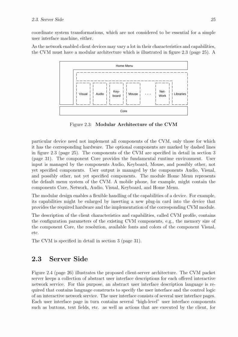
2.3. Server Side 25
coordinate system transformations, which are not considered to be essential for a simpleuser interface machine, either.
As the network enabled client devices may vary a lot in their characteristics and capabilities,the CVM must have a modular architecture which is illustrated in figure 2.3 (page 25). A
Key-board
Net-WorkMouse LibrariesAudioVisual ...
Core
Home Menu
Figure 2.3: Modular Architecture of the CVM
particular device need not implement all components of the CVM, only those for whichit has the corresponding hardware. The optional components are marked by dashed linesin figure 2.3 (page 25). The components of the CVM are specified in detail in section 3(page 31). The component Core provides the fundamental runtime environment. Userinput is managed by the components Audio, Keyboard, Mouse, and possibly other, notyet specified components. User output is managed by the components Audio, Visual,and possibly other, not yet specified components. The module Home Menu representsthe default menu system of the CVM. A mobile phone, for example, might contain thecomponents Core, Network, Audio, Visual, Keyboard, and Home Menu.
The modular design enables a flexible handling of the capabilities of a device. For example,its capabilities might be enlarged by inserting a new plug-in card into the device thatprovides the required hardware and the implementation of the corresponding CVM module.
The description of the client characteristics and capabilities, called CVM profile, containsthe configuration parameters of the existing CVM components, e.g., the memory size ofthe component Core, the resolution, available fonts and colors of the component Visual,etc.
The CVM is specified in detail in section 3 (page 31).
2.3 Server Side
Figure 2.4 (page 26) illustrates the proposed client-server architecture. The CVM packetserver keeps a collection of abstract user interface descriptions for each offered interactivenetwork service. For this purpose, an abstract user interface description language is re-quired that contains language constructs to specify the user interface and the control logicof an interactive network service. The user interface consists of several user interface pages.Each user interface page in turn contains several “high-level” user interface componentssuch as buttons, text fields, etc. as well as actions that are executed by the client, for

26 2. Proposed Client-Server Architecture — Overview
(PROFILE, sessionId = sid, profileItemCodes)
(CVMP, sessionId = sid, cvmpNo = ...,pageMemAdr = ..., cvmPacket = ...)
User
UserInteraction
Time
AUI + CVM Profile
CVMUI
1
2
5
6
3
4
Abstract UserInterface Descriptions
CVM UserInterface
ServiceGenerator
Session Manager
AUI...
(PROFILE, sessionId = sid, cvmProfile = ...)
(GET, sessionId = 0, serviceNo = svNo,pageNo = 0, subpageNo = 0, cvmProfile = ...,
numBytes = 0, dataBytes = [])
Client
CVM
(GET, sessionId = sid, serviceNo = svNo,pageNo = ..., subpageNo = ..., cvmProfile = ...,
numBytes = ..., dataBytes = [...])
CVM Packet Server
...
CVM PacketGenerator
ServiceInstance
AUI + CVM Profile
AUI + CVM Profile
7
CVMUI8
AUI + CVM Profile
(CVMP, sessionId = sid, cvmpNo = ...,pageMemAdr = ..., cvmPacket = ...)
...
9
Generation
Generation
Figure 2.4: Client-Server Session

2.3. Server Side 27
example event handling procedures. The control logic of a network service contains actionsthat are executed on the server side. Each interactive network service is referenced bya well-defined service number. Let AUI be the abstract user interface description of theinteractive network service with the service number svNo.
A new client-server session is initiated by a client request with a GET message from theCVM to the CVM packet server (step 1). Section 2.4 (page 29) gives an overview of theGET and other used protocol methods. The session manager module of the CVM packetserver processes all client requests and stores the session-specific data. The CVM packetserver first assigns a new identification value (sid 6= 0) to the new client-server session. ACVM packet server might serve more than one CVM at the same time and therefore needsthis unique value to distinguish between them when it receives a message from a CVM.The value zero indicates the beginning of a new client-server session.
If the profile data of the CVM which is given by the message item cvmProfile in the GET
message is incomplete, the CVM packet server responds with a PROFILE message to ask forthe missing profile items (step 2). The CVM then sends a PROFILE message to the CVMpacket server that contains these items. Note that the CVM packet server and the serviceinstance can send a PROFILE message to the CVM at any time during the client-serversession.
After all necessary profile data is available, the service generator module generates a client-specific service instance that meets the hardware and software capabilities as well as theuser preferences of the client (step 3). It is generated from the abstract user interfacedescription AUI and from the client description, the CVM profile. It mainly contains thestate machine that implements the control logic of the network service that is specified inthe AUI. The lifetime of the client-specific service instance is limited by the time span ofthe respective client-server session. Its limited lifetime is indicated by the dashed lines inthe figure.
The CVM packet generator generates the CVM user interface CVMUI from the abstractuser interface description AUI and the CVM profile (step 4). This CVM user interface is aCVM program that contains an adapted version of the requested AUI page. This versionmeets the client capabilities and user preferences. The CVM instructions of a CVM userinterface mainly encode the appearance and event handling semantics of the user interfacecomponents at a low level of abstraction. Note that a CVM user interface may contain alluser interface components of the respective AUI page or only a subset, depending on theclient capabilities like memory, screen size, etc. The missing parts may be generated anddelivered in subsequent client requests.
The generated CVMUI is then sent by the client-specific service instance to the requestingCVM in a binary format that is called the CVM packet format (step 5). The transmittedCVM packet is executed by the CVM.
The CVM packet may contain instructions that result in another GET request (step 6).Mostly, this is the case when the user interacts with a particular user interface componentof the currently executed CVM packet, which causes the CVM to execute the respectiveevent handling procedure that may contain such instructions. The GET request may alsocontain data that is encoded in the CVM packet or that results from client-side processingsor user input. This data is sent in the message item dataBytes of the GET message. It isused by the state machine of the service instance as input for server-side processings.
Note that both the contents and format of this data are encoded in the instructions of the

28 2. Proposed Client-Server Architecture — Overview
CVM packet, whereas the CVM packet is generated by the CVM packet generator from thegiven AUI. Thus, the client-server communication and data transfer are mainly managedon the server side and the CVM does not need any “intelligence”. It just executes theinstructions in the received CVM packet.
In addition, the data in dataBytes might be needed by the CVM packet generator forthe generation of subsequent CVM user interfaces. For example, this is the case when theuser of the CVM receives a CVM packet that contains a summary of all data that theuser has input in previous input forms. As a CVM user interface generally depends onuser data that might dynamically change during the client-server session it needs to begenerated each time again on demand. Therefore it is generally not possible to generatethe CVM user interfaces of a given abstract user interface description in the beginning ofthe client-server session all at once.
Steps 6, 8, and 9 are equal to the steps 1, 4, and 5, respectively. Step 7 differs from step3 in that the client-specific service instance already exists and need not be generated anymore during this client-server session. The AUI description and the CVM profile are justpassed by the session manager to this service instance.
In addition to the screen size of the CVM, its memory size is also a key factor in determininghow a user interface needs to be customized for the CVM. If the CVM has enough memory,all parts of an AUI page can be sent in one CVM packet to it. Then, of course, a userinteraction for navigating between the different parts need not cause any CVM requests.However, if the CVM does not have enough memory, the AUI page must be split into smallersubpages, where each CVM packet of a subpage must fit into the memory of the CVM.Then, the CVM packet server first sends to the CVM the CVM packet that contains thesubpage with the starting user interface portion. Each subpage must provide user interfaceelements — or even simpler, just “invisible” event handling procedures — that serve ashyperlinks to the other subpages, in order to enable the user to navigate between them.The activation of such an hyperlink by the user results in a GET request for the demandedsubpage. The CVM packet server then replies with the requested subpage. To reduce theamount of network transactions, the server should try to use the memory of the client asefficiently as possible when partitioning a user interface into smaller subpages. In general,smaller subpages might imply more client-server transactions. As a result, the partitioningof a user interface also leads to an optimization problem with respect to the memory sizeof the client and the number of network transactions.
Drawing an analogy to the field of document preparation systems, the user interface ofan interactive network service corresponds to a document. The abstract description ofthe user interface corresponds to the description of the logical structure of the document,whereas the CVM packets correspond to the layout structure of the document. In addition,the CVM packet generator acts as a rendering engine, whereas the CVM profile representsa collection of formatting constraints.
The abstract specification of user interfaces for interactive network services requires asuitable language. The service providers on the server side can choose such a languagefreely. It is totally their concern how they specify their interactive network services andstore their provided content. For example, the description languages XForms [24], UIML[86], BOSS [67], EmuGen [14] [15], WSDL [21], etc., might be used for specifying abstractuser interfaces and Web services. It is also the service providers’ business, how theygenerate appropriate and valid CVM packets. In addition to the client capabilities anduser preferences, which are technical constraints, the service providers also have to consider
2.4. Communication Protocol 29
layout- and ergonomic-related issues when generating user interfaces for client devices withlimited input and output capabilities.
Compiler technology might be used for the generation of client-specific CVM user inter-faces from abstract specifications. Depending on the specification language, the dynamicgeneration of client-specific service instances and CVM user interfaces from abstract userinterface descriptions for interactive network services might be a quite complex task. There-fore, the CVM packet server might also keep “simpler” user interface descriptions such asHTML/XML documents that do not define complex workflows. Then, the CVM packetgenerator mainly resembles a compiler that translates HTML/XML documents into ap-propriate CVM user interfaces.
As a proof of concept, an exemplary language for abstract user interface descriptions, anexemplary structure for CVM user interfaces, and an exemplary server-side architecturefor the generation of client-specific service instances and CVM packets are presented inthis thesis. These components are specified in detail in the sections 5.1 (page 135), 5.5(page 166), and 5 (page 135), respectively.
2.4 Communication Protocol
The protocol for the client-server communication should be as simple and universal aspossible. On the one hand, any small and restricted client device should be able to im-plement it either in software or even in hardware without great use of system resources.On the other hand, this protocol should be suitable for all kinds of different interactivenetwork services. Therefore, the application-specific protocol mechanisms must be sepa-rated from the elementary ones. The application-specific protocol mechanisms depend onthe particular network service and might be shifted into the control logic of the networkservice. They might also be specified in the abstract description of the corresponding userinterface. In effect, the communication protocol consists then mostly of the elementaryprotocol methods that are essential and always needed.
As a result, the proposed client-server architecture does not adopt the HTTP [10] protocol,which is used in the WWW for the client-server communication. Instead, a new communi-cation protocol, called the CVM packet transfer protocol (CPTP) is proposed in this thesis.CPTP consists only of a few protocol methods. The protocol methods that occur in figure2.4 (page 26) are described here briefly:
• CVMP: (CVMP, sessionId = sid, cvmpNo = ..., pageMemAdr = ..., cvmPacket = ...)This protocol method is used when the CVM packet server sends the CVM packetcvmPacket to the CVM. sessionId contains a value that identifies the current client-server session, because the CVM packet server might serve more than one client at thesame time. cvmpNo contains the number of this CVM packet. pageMemAdr containsthe absolute memory address of the CVM instruction, where the CVM should startexecution, after it has loaded this CVM packet into its memory.
• GET: (GET, sessionId = 0, serviceNo = svNo, pageNo = ..., subpageNo = ...,cvmProfile = ..., numBytes = ..., dataBytes = [...])
This protocol method is similar to the GET and POST methods of the HTTP [10]protocol. It is used by the CVM to send the data in the data array dataBytes to the
30 2. Proposed Client-Server Architecture — Overview
CVM packet server and then request from it the CVMUI page that is addressed bythe page number pageNo and the subpage number subpageNo. sessionId contains avalue that identifies the current client-server session, because the CVM packet servermight serve more than one client at the same time. At the beginning of a new client-server session, the CVM packet server assigns a new value other than zero to the newsession. sessionId has the value zero in the first GET message from the CVM to theCVM packet server. serviceNo contains a well-defined number (svNo) that refersto a particular interactive network service that is offered by the CVM packet serverand requested by the CVM. pageNo and subpageNo each contain an unsigned integernumber. They refer to a particular CVMUI page that belongs to the interactivenetwork service with the number serviceNo. cvmProfile contains the profile dataabout the capabilities and user preferences of the requesting CVM. numBytes containsthe number of bytes of the data array dataBytes. At the beginning of a client-serversession, i.e., when sessionId is zero, pageNo and numBytes usually have the defaultvalue zero.
• PROFILE: (PROFILE, sessionId = sid, cvmProfile = ...) or(PROFILE, sessionId = sid, profileItemCodes)
This protocol method is used by the CVM and the CVM packet server for content ne-gotiation. sessionId contains a value that identifies the current client-server session.cvmProfile contains the profile data about the capabilities and user preferences ofthe requesting CVM. profileItemCodes lists the missing profile items whose valuesare needed by the CVM packet generator.
The CPTP protocol is specified in detail in section 4 (page 127).

Chapter 3
Client Virtual Machine (CVM)
The CVM is motivated and introduced in section 2.2 (page 13). The main task of theCVM is to display downloaded user interfaces for networked clients with different andrestricted hardware capabilities. Therefore, the main design goal is a simple and modulararchitecture with a simple runtime environment to enable hardware implementations evenon very “thin” and cheap clients. In addition, the CVM instructions should allow compactand also scalable encodings of user interfaces to make the CVM applicable to more powerfulclients up to general purpose computers such as PCs or workstations as well. As there isno general and formal approach to “deduce” such a virtual machine, a lot of ideas havebeen examined, tried out, and also rejected mainly with the intuition of an engineer. As aresult, the following proposal for the CVM is made without claiming that it is exclusivelythe best solution.
The proposed CVM architecture with its modules and functional units inside each moduleis illustrated in figure 3.1 (page 31). The optional modules and functional units inside amodel are marked by dashed lines. However, at least one input module, e.g., Keyboard,
Key-board
Net-WorkMouse LibrariesAudioVisual ...
Core
Basic Execution andMemory Access
Home Menu (CVM Packet)
History BufferBookmarks
Menu Interval TimerError Handling Event Handling
Figure 3.1: CVM Modules and Functional Units
Mouse, Audio, etc., and at least one output module, e.g., Visual, Audio, etc., should beavailable to enable user interaction. Other input and output modules may be defined inthe future as well. Except for the Audio module, all the illustrated CVM modules andtheir functional units are going to be discussed in detail in the following sections. The
31

32 3. Client Virtual Machine (CVM)
description of the modules mainly focuses on their behavior and special characteristics.Everything else is left to the implementors’ choice.
3.1 Core
The Core module provides the basic runtime environment. Its characteristic componentsare illustrated in figure 3.2 (page 32). The special registers of the CVM are reserved for
Core
Special Registerfor Register Stack
AccessRegister Stack
regRSP...
R[cvmNumGeneralRegs]
Special Registers
Special Registersfor Instruction and
Memory Access
regSS
regBP
regSP
Memory
Code
Stack
...
...
...
regEventTableAdr...
regEventPar3...
mem[0]
mem[stackSegmentAdr]
mem[cvmMaxMem - 1]
R[1] operandR[2] operand
UndeclaredData
DeclaredData
regIP...mem[codeSegmentAdr]
mem[dataDeclSegmentAdr]
Heap
Special Registers
regTimerSignal...
regTimerInterval...
regTimerHandleAdr...
Basic Execution and Memory Access Error Handlng
regState...
Special Registerfor CVM State
Event Handling
regErrorCode...
Special Register
Interval Timer
regEventPar2...
regEventPar1...
regEventCode...
regEventEnable...
History Buffer Bookmarks Menu
Figure 3.2: CVM Core: Functional Units
special purposes. Mainly, these registers store the current state of the CVM. Note that forthe implementation of the CVM additional special registers might be required. However,as these internal special registers are not needed to specify the characteristic behavior ofthe CVM, they are not specified here and are left to the implementors’ choice.
3.1.1 Data Types
The CVM operates on the data types Int, Nat, and String.
3.1. Core 33
Int, Nat Int numbers are 1-, 2-, 3-, and 4-byte signed two’s-complement integer numberswith values in the ranges of [−27; 27 − 1] for 1-byte, [−215; 215 − 1] for 2-byte, [−223;223 − 1] for 3-byte, and [−231; 231 − 1] for 4-byte Int numbers. Nat numbers are 1-, 2-,3-, and 4-byte unsigned one’s-complement integer numbers with values in the ranges of [0;28−1] for 1-byte, [0; 216−1] for 2-byte, [0; 224−1] for 3-byte, and [0; 232−1] for 4-byte Natnumbers. Multibyte Int and Nat numbers are stored in big-endian order, i.e., the high bytescome first. In the following, the term Int1 (or Nat1) will be used as an abbreviation for“1-byte Int (or Nat)”, the term Int2 (or Nat2) as an abbreviation for “2-byte Int (or Nat)”,and so on. In addition, the term Int<1|...|4> and Nat<1|...|4> will be used to address allthe Int and Nat types, respectively.
The distinction between signed (Int) and unsigned (Nat) integer numbers and the consid-eration of their required byte sizes mainly affects the CVM instructions with immediateoperands and the declaration of integer numbers within the CVM packet. It reduces codesize and thus saves network bandwidth and CVM memory usage, because for each integervalue only the minimum number of required bytes is used in the CVM packet and cor-responding CVM program. Refer to section 3.8 (page 93) for more information on CVMpackets. The Nat type is useful, because unsigned integer numbers in the ranges of [27;28−1], [215; 216−1], and [223; 224−1] need 1, 2, and 3 bytes, when encoded as Nat numbers,but 2, 3, and 4 bytes, when encoded as Int numbers, respectively.
Larger integer numbers, from 5 bytes up to 8 bytes, and floating point numbers are notsupported directly by the CVM, as they are scarcely needed for user interfaces — ac-cording to the author’s point of view. When necessary, these numbers must be emulatedby combining two or more directly supported integer numbers and providing appropriateprocedures that implement their arithmetics. These procedures can be provided explic-itly by the CVM programmer or packet generator, or implicitly by particular Core libraryfunctions. Refer to section 3.5 (page 83) for more information on library functions.
String Strings are character sequences. There are two binary string formats:
String = { Nat1 length; // 0 < length ≤ 255
Nat1[length] bytes }or{ Nat1 0;
Nat2 length; // 0 ≤ length ≤ 65535
Nat1[length] bytes }
The byte array bytes contains UTF-8 [89] string characters. Multibyte UTF-8 charactersare stored in big-endian, i.e., high byte first, order. Note that the value of length representsthe number of bytes in the byte array, but not the length of the resulting string. The secondstring representation is to enable longer strings, i.e., strings whose UTF-8 encodings requiremore than 255 bytes. However, the shorter binary string format should suffice in most cases.The binary representation of an empty string is { Nat1 0; Nat2 0 }.
3.1.2 Operation Modes
In order to address a broad range of client devices with different hardware complexitiesand system resources, the CVM can be implemented either as a 16- or 32-bit CVM. In the
34 3. Client Virtual Machine (CVM)
following, the term cvmIntLen is used to denote the byte length of an integer number on agiven CVM implementation, depending on the operation mode (or equivalently called CVMmode). In addition, the CVM types Int and Nat often are also used in the following forInt<cvmIntLen> and Nat<cvmIntLen>, respectively, i.e., their byte lengths are cvmIntLen.
16-Bit CVM On a 16-bit CVM, cvmIntLen is 2. A 16-bit CVM operates only on integernumbers with at most 16 bits. The general purpose registers of the register stack and thememory stack items are each 16 bit wide. The special registers are also 16 bits wide, exceptfor some special registers like regRSP, regColorRed, etc., which might require less bits. Alldata items in memory including the memory stack items are 16-bit aligned. The memorysize of a given 16-bit CVM implementation can be at most 216, i.e., cvmMemMaxAdr ∈ [0;216 − 1], with cvmMemMaxAdr referring to the highest memory address of a given CVMimplementation. In addition, the memory load and store instructions loada, loadr, storea,and storer each access 16-bit signed integer numbers (Int2).
32-Bit CVM On a 32-bit CVM, cvmIntLen is 4. A 32-bit CVM operates only on integernumbers with at most 32 bits. The general purpose registers of the register stack and thememory stack items are each 32 bit wide. The special registers are also 32 bits wide, exceptfor some special registers like regRSP, regColorRed, etc., which might require less bits. Alldata items in memory including the memory stack items are 32-bit aligned. The memorysize of a given 32-bit CVM implementation can be at most 232, i.e., cvmMemMaxAdr ∈ [0;232 − 1], with cvmMemMaxAdr referring to the highest memory address of a given CVMimplementation. In addition, the memory load and store instructions loada, loadr, storea,and storer each access 32-bit signed integer numbers (Int4). In addition, the instructionsaload4, astore4, loadc3, loadc4, loadcu2, loadcu3, setcolor32, setbgcolor32, and setfont32 areonly supported by a 32-bit CVM.
3.1.3 Register Stack
The register stack is a set of 2- or 4-byte general purpose registers, dependent on the CVMmode. It serves as a quick operand stack for the CVM instructions. Except for a fewinstructions that have immediate operands, the instructions usually fetch their operandsfrom the register stack. Immediate operands of an instruction appear in the CVM programright after the opcode. A possible result of an instruction is always pushed onto the topof the register stack. Therefore, the CVM code is a kind of stack machine or 0-addresscode and the register stack might be called operand stack, as well. Figure 3.2 (page 32)illustrates the register stack.
cvmNumGeneralRegs The term cvmNumGeneralRegs is used for the total number ofgeneral purpose registers in the register stack of a given CVM implementation. The totalnumber of general purpose registers can vary for each CVM implementation. However,there must be enough registers to store at least all the operands of each instruction andto enable further computation on the register stack. For example, the computation of thelast operand of a given instruction with n operands by an addition of the two top-mostregister stack values causes a general stack depth of at least n+ 1, which requires at leastn+ 1 registers. Approximately, 10 general purpose registers might be sufficient.

3.1. Core 35
regRSP The special register regRSP (“Register Stack Pointer”) contains a Nat1 numberthat indexes the top-most general purpose register in the register stack. The top-mostgeneral purpose register — also called the top of the register stack — is the general purposeregister that contains the most recently pushed value. The general purpose registers areindexed starting with 1. Therefore, the value of regRSP also corresponds to the numberof available operands on the register stack. The term R[i] (1 ≤ i ≤ cvmNumGeneralRegs)represents the ith general purpose register or its value. The initial value of regRSP is zero,i.e., at the beginning of program execution the register stack is naturally empty. The valueof regRSP is mainly affected and modified implicitly by the register stack behavior of theinstructions. However, the instructions rdup, rempty, rskip, and rswap particularly aim atthe management of the register stack.
Loading Values onto the Register Stack As already mentioned, values are pushedalways onto the top of the register stack. The basic register stack loading instructionsare loadc<1|...|4>, loadcu<1|...|3>, loadc 0, loadc 1, and loadc m1. Other instructions,e.g., arithmetic operations, might produce new values onto the register stack as well. Theloading process of a new value v consists of the following steps: First, the CVM checks ifthe value of the special register regRSP is below cvmNumGeneralRegs. If this is the case, theCVM increments the value of regRSP by 1 and then stores v into the register R[regRSP]. Anerror condition is reached, if the value of regRSP is not below cvmNumGeneralRegs beforeloading. Then, instead of loading, the CVM aborts execution of the current instructionand starts error handling with the error code RegisterStackOverflow. Refer to section 3.1.5(page 41) for more information on error handling.
Retrieving Values from the Register Stack An operand consuming instructionfetches its register stack operands either from the current top of the register stack —which is referred to as Dynamic Popping — or from designated general purpose registersinside the register stack — which is referred to as Static Popping. The appropriate operandfetching method of each instruction is specified in the instruction reference in section 3.9.2(page 100).
Dynamic Popping The process of Dynamic Popping for an instruction that needsn (n > 0) operands consists of the following steps: First, the CVM checks if the valueof the special register regRSP is at least n. If this is the case, the n top-most values ofthe register stack, i.e., R[regRSP], ..., R[regRSP− n+ 1], are popped and used as operandsfor the instruction. After all, regRSP is decremented by n. An error condition is reached,if the value of regRSP is below n before popping. Then, instead of popping, the CVMaborts execution of the current instruction and starts error handling with the error codeRegisterStackUnderflow. Refer to section 3.1.5 (page 41) for more information on errorhandling.
The instructions that perform Dynamic Popping, e.g., arithmetic instructions, are calledin-between instructions. Their main purpose is to compute the operands for the so calledfinal instructions, which perform Static Popping.
Static Popping The process of Static Popping for an instruction that needs n(n > 0) operands consists of the following steps: First, the CVM checks if the value of the
36 3. Client Virtual Machine (CVM)
special register regRSP is equal to n. If this is the case, the values in the register stack, i.e.,R[1], ..., R[n], are popped and used as operands for the instruction. Then, regRSP is setto its initial value zero. An error condition is reached, if the value of regRSP is not equalto n before popping. Then, instead of popping, the CVM aborts execution of the currentinstruction and starts error handling with the error code RegisterStackUnderflow, if regRSPis less than n, or with the error code RegisterStackStaticOverflow, if regRSP is greater thann. Refer to section 3.1.5 (page 41) for more information on error handling.
The instructions that perform Static Popping are called final instructions. The mainpurpose of Static Popping is to gain more runtime performance during operand fetching,because each operand is located in a designated register with a known index. For example,the drawing instructions of the CVM module Visual are final instructions.
3.1.4 Memory
The memory consists of an array of bytes that can be read and written during executionof a CVM program. The memory size depends on the given CVM implementation. Eachbyte in memory can be addressed by its array index, whereas counting starts with 0. Theterm mem[i] (0 ≤ i ≤ cvmMemMaxAdr) represents the ith byte in memory or its value.The highest memory address of a given CVM implementation is referred to with the termcvmMemMaxAdr. Generally, all multibyte Int and Nat numbers and UTF-8 [89] charactersare stored in big-endian, i.e., high byte first, order.
During execution of a CVM program, the memory is partitioned into four sections: theData, Code, Stack, and the optional Heap section. Figure 3.2 (page 32) illustrates thepartitioning of the memory.
Basically, every byte in any memory section can be read or written. Therefore, it istechnically feasible that the CVM program overwrites its own instructions in the Codesection during execution. Whether this is useful, is left to the responsibility of the CVMprogrammer or packet generator.
If during a memory access the resulting absolute memory address is not inside the range[0; cvmMemMaxAdr], the CVM aborts execution of the current instruction and starts errorhandling with the error code IllegalMemoryAddress. Refer to section 3.1.5 (page 41) formore information on error handling.
Absolute Memory Access An absolute memory address is always a Nat number. Theinstructions loada, storea, aload<1|2|4>, and astore<1|2|4> address the memory absolutelywith their address operands. The address operands reside on the register stack and areabsolute indices into the memory, respectively. The instruction loada reads a signed integernumber in big-endian order from memory and pushes its value onto the register stack. Theinstruction storea pops a signed integer number from the register stack and writes its valueinto memory in big-endian order. The byte length of a signed and unsigned integer numberdepends on the CVM mode and is referred to with the term cvmIntLen. It is 2 on a 16-bitCVM and 4 on a 32-bit CVM. The instructions aload<1|2|4> and astore<1|2|4> read andwrite 1-, 2-, or 4-byte integer numbers from and into arrays in memory, respectively.

3.1. Core 37
Relative Memory Access A relative memory address is always an Int number, i.e., itcan be positive as well as negative. The instructions loadr and storer address the memoryrelatively with their address operands. The address operands reside on the register stackand are relative indices into the memory segment that starts at the base address given bythe special register regBP, respectively. The CVM computes the resulting absolute memoryaddress by adding the relative address operand to the base address given by regBP. Theresulting memory address can point to any byte in every memory section. The instructionloadr reads a signed integer number in big-endian order from the memory and pushes itsvalue onto the register stack. The instruction storer pops a signed integer value from theregister stack and writes its value into memory in big-endian order. Again, the byte lengthof a signed and unsigned integer number depends on the CVM mode and is referred towith the term cvmIntLen. It is 2 on a 16-bit CVM and 4 on a 32-bit CVM.
When not stated explicitly in this thesis that a memory address is relative, a memoryaddress is always regarded as being absolute.
The main purpose of relative memory access instructions is to access procedure parametersand local variables that reside on the memory stack. For this topic, refer to section 3.1.4.2(page 39).
regBP The special register regBP (“Base Pointer”) contains an absolute memory addressthat marks the beginning of a memory segment anywhere in memory. It is used by theinstructions loadr and storer as a base address for retrieving and storing values from andinto memory. The value of regBP is modified by the instructions setbp, newstackframe, andoldstackframe. The initial value of this register is zero. The main purpose of regBP is topoint to the current stack frame that contains the parameters and local variables of thecurrently executed procedure. For this topic, refer to section 3.1.4.2 (page 39).
The memory address in regBP is a Nat value and the byte length of this register depends onthe given CVM implementation, but must be adequate to address the whole CVM memory.This rule also applies to the other special registers that store absolute memory addresses.
3.1.4.1 Data and Code
The Data section can be subdivided into the Undeclared and the Declared Data sec-tion, which contain undeclared and declared data, respectively. The Undeclared Datasection starts at the memory address 0 and ends at dataDeclSegmentAdr − 1, whereasthe Declared Data section starts at the memory address dataDeclSegmentAdr and endsat codeSegmentAdr− 1. The Code section starts at the memory address codeSegmentAdrand ends at stackSegmentAdr−1. The Code section contains the instructions of the CVMprogram.
dataDeclSegmentAdr, codeSegmentAdr, and stackSegmentAdr are items of the CVMpacket, which is transmitted from the CVM packet server to the CVM. Mainly, the CVMpacket contains declared data with initial values and CVM instructions. Refer to section3.8 (page 93) for more information on the structure of CVM packets and their items.
regIP The special register regIP (“Instruction Pointer”) contains the absolute memoryaddress of the opcode or of an immediate operand of the currently executed instruction.
38 3. Client Virtual Machine (CVM)
The CVM increments regIP automatically during execution to fetch the next opcode orimmediate operand unless the currently executed instruction sets regIP explicitly. Its valuecan be set or modified explicitly by the control flow instructions call, ret, jmp, je, jne, jl, jle,and page. If the CVM fetches the opcode or an immediate operand of an instruction whileregIP has an address outside the interval [0; cvmMemMaxAdr], the CVM aborts execution ofthe current instruction and starts error handling with the error code IllegalMemoryAddress(page 43).
When loading the declared data items and instructions from a CVM packet into memory,the CVM sets regIP to the value of the CVM packet item codeSegmentAdr. Execution ofthe loaded CVM program starts at this memory address. Refer to section 3.8 (page 93)for more information on CVM packets and their items.
Note that during execution of a CVM program regIP can be loaded with any memoryaddress that points to any byte in any memory section. Therefore, execution of CVMinstructions outside the Code section in memory is technically feasible. Whether this isuseful, is left to the responsibility of the CVM programmer or packet generator.
3.1.4.2 Stack
The Stack section starts at the memory address stackSegmentAdr and ends at cvmMem-MaxAdr. stackSegmentAdr is an item of the CVM packet, which is transmitted from theCVM packet server to the CVM. Commonly, the stack is used for storing temporary andlocal variables, and for storing parameters and return addresses during procedure calls.Each stack item can hold a whole integer number. Therefore, the byte length of a stackitem depends on the CVM mode and is referred to by the term cvmIntLen. It is 2 on a16-bit CVM and 4 on a 32-bit CVM.
regSS The special register regSS (“Stack Segment”) contains the absolute memory ad-dress of the beginning of the memory stack. The value of this register cannot be modifiedby the CVM instructions during execution of a CVM program. Its initial value is set tothe value of the CVM packet item stackSegmentAdr when the CVM packet is loaded intomemory. Refer to section 3.8 (page 93) for more information on CVM packets and theiritems.
regSP The special register regSP (“Stack Pointer”) contains the memory address thatmarks the top of the memory stack, i.e., it contains the memory address of the nextunused memory stack element. The value of this register is modified by the instructionsaddsp, decsp, incsp, push, pop, call, ret, newstackframe, and oldstackframe. The initial andminimum value of regSP is equal to the value of regSS. The maximum value of regSP isequal to the value of cvmMemMaxAdr.
Loading Values onto the Stack The instruction push pops an integer number from theregister stack and pushes its value onto the memory stack. The loading process consists ofthe following steps: First, the CVM checks if the value of the special register regSP is lessthan or equal to cvmMemMaxAdr− cvmIntLen + 1. If this is the case, the CVM stores thevalue into the memory cells mem[regSP], mem[regSP + 1], ..., mem[regSP + cvmIntLen− 1]in big-endian order. Then, the CVM increments regSP by the value cvmIntLen. An error
3.1. Core 39
condition is reached, if the value of regSP is not less than or equal to cvmMemMaxAdr −cvmIntLen + 1 before loading. Then, instead of pushing, the CVM aborts execution of thecurrent instruction and starts error handling with the error code StackOverflow. Refer tosection 3.1.5 (page 41) for more information on error handling.
Retrieving Values from the Stack The instruction pop pops an integer number fromthe memory stack and pushes its value onto the register stack. The retrieving process con-sists of the following steps: First, the CVM checks if the value of the special register regSSis less than or equal to the value of regSP− cvmIntLen. If this is the case, the CVM loadsthe value that is stored in the memory cells mem[regSP − 1], ..., mem[regSP − cvmIntLen]in big-endian order onto the top of the register stack. Finally, the CVM decrements regSPby the value cvmIntLen. An error condition is reached, if the value of regSS is not lessthan or equal to regSP− cvmIntLen before retrieving. Then, instead of popping, the CVMaborts execution of the current instruction and starts error handling with the error codeStackUnderflow. Refer to section 3.1.5 (page 41) for more information on error handling.
Procedure Parameters and Local Variables Figure 3.3 (page 40) illustrates the stackframe of a procedure proc with the return value result, the parameters par1 , ..., parn , andthe local variables loc1 , ..., locm at an arbitrary point of time during execution after ithas been called by main. Let the return value, the parameters, and the local variables beinteger numbers. The corresponding CVM assembler code fragment might be as follows:
main:
incsp // Reserve space for result on memory stack<Load value of par1 onto register stack> push // Load par1 onto memory stack...<Load value of parn onto register stack> push // Load parn onto memory stackloadcr proc call // Call procedure proc
loadc −n addsp // Discard procedure parameters on memory stackpop // Load result from memory stack onto register stack...halt
proc:
loadc n + 1 newstackframe // Adjust regBP to new stack frameloadc m addsp // Reserve space for local variables on memory stack...loadc −m addsp // Discard local variables on memory stackoldstackframe // Restore regBP to previous stack frameret // Return to caller main
Refer to sections B (page 216) and B.3 (page 224) for a description of the CVM assemblerand the macros loadc and loadcr. Refer also to the instruction reference in section 3.9.2(page 100) for a description of the used CVM instructions.
Then, the relative memory addresses of the result, the parameters pari (1 ≤ i ≤ n), andthe local variables locj (1 ≤ j ≤ m) are 0, i ∗ cvmIntLen, and (n + 2 + j) ∗ cvmIntLen,
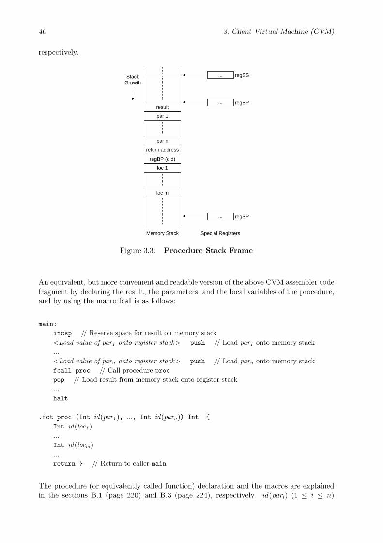
40 3. Client Virtual Machine (CVM)
respectively.
StackGrowth
Memory Stack
regSS
regSP...
...
regBP...result
par 1
par n
return address
regBP (old)
loc 1
loc m
Special Registers
Figure 3.3: Procedure Stack Frame
An equivalent, but more convenient and readable version of the above CVM assembler codefragment by declaring the result, the parameters, and the local variables of the procedure,and by using the macro fcall is as follows:
main:
incsp // Reserve space for result on memory stack<Load value of par1 onto register stack> push // Load par1 onto memory stack...<Load value of parn onto register stack> push // Load parn onto memory stackfcall proc // Call procedure proc
pop // Load result from memory stack onto register stack...halt
.fct proc (Int id(par1 ), ..., Int id(parn)) Int {
Int id(loc1 )...Int id(locm)...return } // Return to caller main
The procedure (or equivalently called function) declaration and the macros are explainedin the sections B.1 (page 220) and B.3 (page 224), respectively. id(pari) (1 ≤ i ≤ n)
3.1. Core 41
and id(locj ) (1 ≤ j ≤ m) represents the name of the ith parameter or j th local variable,respectively. A complete example that illustrates the access of procedure parameters andlocal variables within a procedure declaration is given in section B.6 (page 237).
3.1.4.3 Heap
The Heap section is used for storing all data that are created during runtime, i.e., dynam-ically during execution of a CVM program. The Heap section is optional and logicallyseparated from the other memory sections Data, Code, and Stack, i.e., it does not needto belong to the same address space. In addition, the Heap section does not need to beexplicitly and directly mapped by a given CVM implementation right after the Stack sec-tion. For example, the CVM might be emulated in software and the heap of the nativecomputer architecture might be used for the Heap section.
In the following, the term “(CVM) memory” only refers to the Data, Code, and Stacksection, whereas the Heap section is mentioned explicitly when referred to.
The Heap section cannot be accessed by the common memory load and store instructionsloada, loadr, storea, storer, aload<1|2|4>, and astore<1|2|4>, but only with the special heapmanagement instructions new, free, hload, and hstore to avoid ambiguities between equalmemory addresses of different address spaces. A given CVM implementation only needsto support the heap management instructions if it possesses a Heap section.
The CVM profile item cvmLibraries reports to the CVM packet server whether the CVMpossess a Heap section. Refer to section 3.7 (page 89) for more information on the CVMprofile.
If a given CVM implementation does not have a Heap section but dynamic data is stillneeded in a particular application, the CVM programmer or packet generator can modelthe heap in the Data section and has to provide explicit procedures in the CVM code forits management. However, this is not going to be discussed here in more detail.
3.1.5 Error Handling
During loading a CVM packet and executing a CVM program errors might occur. Forexample, the format of the CVM packet might be malformed or the register stack mightoverflow during execution of a particular CVM instruction.
regErrorCode The special register regErrorCode stores the error code number of the re-cently occurred error. Refer to section 3.1.5.2 (page 42) for a complete list of all errortypes and their respective error codes. The value of this register cannot be modified bythe CVM instructions, but is set automatically by the CVM each time an error occurs. Itsinitial value is zero.
3.1.5.1 Error Processing
If an error occurs, the CVM aborts its current activity, i.e., loading a CVM packet orexecuting a CVM program, and performs the following steps:
42 3. Client Virtual Machine (CVM)
First, the CVM writes the respective error code number into the special register regError-Code and sets the special register regState to the state value Error, i.e., it moves to thestate Error. Refer to section 3.1.10 (page 58) for more information on CVM states.
Then, the CVM deactivates the timer, if there is one and if it has been activated before.Refer to section 3.1.9 (page 57) for more information on interval timers.
Next, the CVM outputs an error message to the output device to inform the user. Depend-ing on the type of the output device, i.e., a screen or speaker, the CVM outputs a writtenand/or an acoustic version of the error message. The written version of the error messagehas the following form: "CVM Error: error name ". Section 3.1.5.2 (page 42) contains alist of all error names and their respective error code numbers. The CVM first clears thescreen and then writes the error message on the blank screen. The background color of thescreen, the foreground color and the font of the error message are not specified here andcan be chosen freely by the CVM implementor. The acoustic version of the error messagemight be a particular signal tone or a voice that reads out the written version of the errormessage. If there is both a speaker and a screen existing, the CVM always outputs thewritten error message on the screen, whereas the acoustic error message is optional.
After the CVM has output the error message, it clears the event queue, i.e., it discardsall buffered events that have not been processed yet, and waits until the user confirms theerror message. If there is a keyboard available, the user can press the Enter key. If thereis a microphone available, the user can reply by saying ”OK”. Alternatively, the user canas well raise one of the builtin events, e.g., menu home. Refer to section 3.1.6.3 (page 49)for more information on builtin events. Refer also to the CVM state transitions in section3.1.10 (page 58).
Finally, if the CVM program has been received from a CVM packet server, the CVMsends a notification message to the CVM packet server by using the protocol methodERROR. Refer to section 4.2 (page 129) for more information on the message format of thisprotocol method. The main purpose of the notification message is to provide additionalinformation to enable bug fixes on the server side.
How the CVM proceeds after error processing depends on how the user has confirmed theerror message. If the user has acknowledged with the Enter key or by speaking somethinglike “OK” into the microphone, the CVM initializes itself and continues executing thecurrent CVM packet. However, if the user has confirmed with one of the builtin events,the CVM performs the appropriate actions. Refer also to section 3.1.10 (page 58) for moreinformation on the CVM’s runtime behavior and particularly to the actions in the CVMstate Error.
3.1.5.2 Error Codes
The instruction reference in section 3.9.2 (page 100) specifies for each instruction whicherrors might occur during its execution. In the following, the currently supported errorcodes are listed alphabetically and described using the following description format:
error name = error codeverbose description
The error name represents the mnemonic of the error code. The error code is a uniqueNat1 number greater than zero identifying a particular error type.
3.1. Core 43
DivisionByZero = 1This error occurs, if an (arithmetic) instruction tries to divide by zero.
IllegalMemoryAddress = 2This error occurs with instructions that deal with memory addresses, e.g., with memoryread and write instructions, if the involved memory address is out of the range [0; cvm-MemMaxAdr].
ImageLoadFailure = 3This error occurs with instructions and library functions such as pixmap, etc., that loadimages from memory, if something goes wrong during the loading process, e.g., the imageformat is malformed.
InvalidScreenSection = 4This error occurs only with the instructions mem2screen and screen2mem, if the specifiedrectangular area is not completely inside the visual drawing area of the CVM.
MalformedHomeMenu = 5This error occurs, if the format of the HomeMenu CVM packet is malformed, when it isloaded into memory. Refer to sections 3.6 (page 86) and 3.8 (page 93) for more informationon the HomeMenu and on the CVM packet format, respectively.
MalformedCPTPMessage = 6This error occurs during a CPTP session, if the received CPTP message is malformed.Refer to section 4.1 (page 127) for more information on the CPTP message format and tosection 4.2 (page 129) for more information on CPTP messages with the protocol methodERROR.
MalformedCVMPacket = 7This error occurs, if the format of the CVM packet that is currently being loaded intomemory is malformed. Refer to section 3.8 (page 93) for more information on the CVMpacket format. The CVM packet has been received recently from a CVM packet serverover the network.
MalformedCVMProfile = 8This error occurs during a CPTP session, if the format of the CVM profile that the CVMhas sent to a CVM packet server is malformed. Refer to section 3.7 (page 89) for moreinformation on the CVM profile format and to section 4.2 (page 129) for more informationon CPTP messages with the protocol method ERROR.
NetworkError = 9This error occurs with the instructions rcv, send, and sendrcv, if the specified data cannotbe received from or sent to the specified CVM packet server due to any network failurethat might occur during the connection establishment or data transmission.
44 3. Client Virtual Machine (CVM)
NoDNSLookup = 10This error occurs with the instructions rcv, send, and sendrcv, if the specified host addressis a DNS [45] name, but the given CVM implementation cannot perform automatic DNSlookup. Refer also to the profile item cvmDNSLookup (page 90).
RegisterStackOverflow = 11This error occurs, if an instruction tries to push a value onto the register stack that alreadycontains cvmNumGeneralRegs elements, i.e., regRSP = cvmNumGeneralRegs before pushing.
RegisterStackStaticOverflow = 12This error occurs with a final instruction, i.e., an instruction that performs Static Popping,if the register stack before popping contains more elements than the instruction needs asoperands.
RegisterStackUnderflow = 13This error occurs with an instruction, if the register stack before popping contains lesselements than the instruction needs as operands.
StackOverflow = 14This error occurs, if during execution regSP reaches a value greater than cvmMemMaxAdr+1. For example this is the case, if an instruction tries to push a new value onto a full memorystack, i.e., before the push operation the value of regSP is greater than cvmMemMaxAdr−cvmIntLen + 1. Refer to section 3.1.2 (page 33) for more information on cvmIntLen.
StackUnderflow = 15This error occurs, if during execution regSP reaches a value less than regSS. For examplethis is the case, if an instruction tries to pop a value from an empty memory stack, i.e.,before the pop operation the value of regSP−cvmIntLen is less than regSS. Refer to section3.1.2 (page 33) for more information on cvmIntLen.
UnexpectedCPTPMethodCode = 16This error occurs during a CPTP session, if the received CPTP message has an unexpectedprotocol method. Refer to section 4.2 (page 129) for more information on CPTP messageswith the protocol method ERROR.
UnknownFont = 17This error occurs with the instructions setfont, setfont32, setfontcode, and setfontsize, if theresulting font is not supported by the given CVM implementation. Refer to section 3.2.3(page 79) for more information on fonts.
UnknownMouseFont = 18This error occurs with the instruction setmousefont, if the specified mouse font code is notsupported by the given CVM implementation. Refer to section 3.3 (page 81) for moreinformation on the mouse.
3.1. Core 45
UnknownLibraryFunction = 19This error occurs with the instruction lib, if the CVM encounters a library function codethat it does not support. Refer to section 3.5 (page 83) for more information on the libraryfunctions.
UnknownOpcode = 20This error occurs, if the CVM encounters an unknown instruction opcode during the exe-cution.
Comments The error codes can also be grouped according to the CVM modules andtheir functional units they belong to, respectively:
• Core:
– Execution: DivisionByZero, RegisterStackOverflow, RegisterStackStaticOverflow,RegisterStackUnderflow, StackOverflow, StackUnderflow, UnknownOpcode, Mal-formedCVMPacket
– Memory Access: IllegalMemoryAddress
– Error Handling: (So far, no error codes)
– Event Handling: (So far, no error codes)
– History Buffer: (So far, no error codes)
– Bookmarks Menu: (So far, no error codes)
– Interval Timer: (So far, no error codes)
• Visual: InvalidScreenSection, UnknownFont
• Audio: (Not covered in this thesis)
• Keyboard: (So far, no error codes)
• Mouse: UnknownMouseFont
• Network: MalformedCPTPMessage, MalformedCVMProfile, NetworkError, NoDNSLookup,UnexpectedCPTPMethodCode
• Libraries: UnknownLibraryFunction
• Home Menu: MalformedHomeMenu
3.1.6 Event Handling
Event handling enables user interaction. Here, an event is a notification of a user actionon an input module of the client device. For example, the user might press a key on thekeyboard, move the mouse, etc. The event data, i.e., the data describing the event, consistsof the event code and possibly some event parameters. The event code is a positive integernumber that identifies the action the user has performed on the input module, e.g., a keypress. The event parameters depend on the event code and provide additional information
46 3. Client Virtual Machine (CVM)
on the event, e.g., the key code of a pressed key. Refer to section 3.1.6.4 (page 49) for acomplete reference of the event code and the event parameters for each event type.
Events occur asynchronously during program execution and are buffered in an event queuein the FIFO (First In, First Out) manner. The length of the event queue is left to theimplementors’ choice. Naturally, it must be at least one. After the user has performedsome action on an input device, e.g., pressed a key, the CVM inserts the correspondingevent data, i.e., the event code number and the event parameters, into the event queue.However, if the event queue is already full, the new incoming event is discarded, instead.
The CVM regularly checks the event queue only in the states Error, EventProcessBuiltin,Execute, CptpGET, and Wait, i.e., regState = Error ∨ EventProcessBuiltin ∨ Execute ∨CptpGET ∨ Wait.
In the following, the event handling of the CVM is described without going too much intodetails for reasons of readability. Refer to section 3.1.10 (page 58) for more details on eventhandling, CVM states, and the overall state behavior of the CVM.
3.1.6.1 Event Processing
Here it is described how the CVM behaves when it checks the event queue in the statesExecute or Wait, i.e., regState = Execute ∨ Wait.
If there is an event in the event queue, the CVM removes the event from the event queue andwrites the event code into the special event register regEventCode and the event parametersinto the special event parameter registers regEventPar<1|2|...>. Next, the CVM sets thevalue of the special state register regState to the state value EventProcess.
In the state EventProcess the CVM first checks whether the event code matches the eventcode of a builtin event. If this is the case, it sets the value of the special state registerregState to the state value EventProcessBuiltin and processes the builtin event. Refer tosection 3.1.6.3 (page 49) for more information on builtin events.
However, if the event code does not match the event code of a builtin event, the CVM checksnext in the state EventProcess whether the value of the special event register regEventEnableis zero. If this is the case, the event will not be further processed and is discarded. The userthen has to wait until the value of that register is set to a non-zero value by the instructionenableevents within the CVM program and then repeat his/her input activity.
If regEventEnable is not zero, the CVM checks the event table from top to bottom, whetherthere is an entry with an event code that corresponds to the event code of the currentlyprocessed event. The event table is part of the CVM program and begins in memory at theabsolute address given by the special register regEventTableAdr. Its binary data structureis described in section 3.1.6.2 (page 48). If there is an event table entry with an event codethat corresponds to the event code of the currently processed event, the CVM first savesthe current values of the special registers regIP, regRSP, regSP, regBP, the previous state— i.e., the state, when the CVM has detected the event in the event queue —, and theregister stack values. It is left to the implementors’ choice whether these values are savedinto memory, e.g., onto the memory stack, or into some internal CVM structures. Then,the CVM loads the instruction pointer register regIP with the instruction address given bythe found event table entry and sets the special registers regRSP and regBP to the valuezero. Finally, it sets the special state register regState with the state value EventExecute

3.1. Core 47
and continues execution with the instruction at the address given by the new value of regIP.This instruction address marks the beginning of the respective event handling subroutinecode for this type of event. As well as the event table, the event handling subroutine code isalso specified by the CVM programmer or packet generator and thus it is a part of the CVMpacket within the Code section. Event handling terminates when the CVM encounters thehalt instruction in the event handling subroutine code. After event handling, the CVMreloads the previously saved values into the special registers regIP, regRSP, regSP, regBP,and regState, respectively. It also reloads the previously saved register stack values andresumes its previously interrupted activity.
If there is an event table entry with the event code 1, then the CVM aborts checking thecurrent event table, jumps to the parent event table, and starts checking that event tablein the same manner.
However, if there is no event table entry with an event code that corresponds to the eventcode of the currently processed event the CVM terminates event processing and resumesits previous activity.
Not checking the event queue in the states EventProcess and EventExecute ensures that animmediately following event cannot overwrite the current values of the regEventCode andregEventPar<1|2|...> registers while the current event is still being processed or its eventhandling subroutine is still being executed. As a result, successive events are processedcompletely one after another without mutual interference.
3.1.6.2 Event Registers
Several special registers are involved in the event handling process, called event registers.
regEventCode The special register regEventCode contains the event code, i.e., a Natnumber, of the currently or recently processed event. Refer to section 3.1.6.4 (page 49) fora complete reference of all event codes. The value of this register is set automatically bythe CVM during event processing and cannot be modified by the CVM instructions. Itsinitial value is zero.
regEventEnable The special register regEventEnable serves as a flag register. If its valueis not zero, then all incoming events will be processed. Otherwise, all incoming events willbe discarded — except for the builtin events. Refer to section 3.1.6.3 (page 49) for moreinformation on builtin events. The value of this register is modified by the instructionsenableevent and disableevent. Its initial value is zero.
regEventPar1, regEventPar2, regEventPar3 The special event parameter registers reg-EventPar<1|2|3> contain the event parameters of the currently processed event. The eventparameters are integer (Int) values. Refer to section 3.1.6.4 (page 49) for a completereference of the event parameters for each event type. The initial values of these registersare undefined. Note that the values of these registers are only defined, when an event iscurrently processed. Therefore, the access to these values should only take place in theprovided event handling subroutines. Otherwise, the values of these registers are undefined.So far, only three event parameter registers are needed. Future releases of the CVM mighthave more, if necessary.
48 3. Client Virtual Machine (CVM)
regEventTableAdr The special register regEventTableAdr contains the absolute memoryaddress of the beginning of the event table in memory. The CVM only accepts an eventfor further processing if the value of this register is greater than zero. The value of thisregister is set by the instruction seteventtableadr. This instruction occurs in the CVMprogram usually after the user interface components have been placed onto the outputmodule, e.g., drawn onto the screen. This instruction is also used to change the inputfocus of an graphical user interface component. The initial value of this register is zero,because user interaction generally starts after the user interface components have beenplaced onto the output module.
The event table is specified by the CVM programmer or packet generator and therefore itis a part of the CVM program. The binary data structure of an event table is as follows:
EventTable = { EventTableEntry [ ] entries ;Int<cvmIntLen> 0 }
EventTableEntry = { Int<cvmIntLen> eventCode; // eventCode > 0
Int<cvmIntLen> memAdr }
An event table is a (possibly empty) list of event table entries, whereas each entry consistsof an event code (eventCode) and the absolute memory address (memAdr) of an instruction.However, if eventCode is 1, then memAdr contains the memory address of the parent eventtable. Refer to section 3.1.2 (page 33) for more information on cvmIntLen. The end of thelist is indicated by the value 0 for the event code. During event processing, the CVM checksthe event table from the beginning to the end. If the event code of an entry (eventCode)equals the event code of the currently processed event, the CVM loads the instructionpointer register regIP with the corresponding memory address and proceeds there with theexecution. This memory address marks the beginning of the appropriate event handlingsubroutine which is specified by the CVM programmer or packet generator and thus is apart of the CVM program within the Code section. However, if eventCode is 1, the CVMjumps to the event table at the memory address memAdr and starts checking that eventtable. Note that it is left to the responsibility of the CVM programmer or packet generatorto avoid infinite recursion. If eventCode is 0, the CVM terminates event processing andresumes its previous activity.
3.1.6.3 Special Events
In addition to the ordinary events there are also special events. They are grouped intoshortcut events and builtin events.
Shortcut Events Shortcut events are very often needed in user interfaces and are there-fore defined separately and directly. Generally, event subroutine code can be defined fortheir behavior in the event table the same way as it is defined for any other ordinary event.But under certain conditions, i.e., when the CVM is in a particular state, e.g., Error, par-ticular shortcut events might also have a predefined meaning, which is specified by theCVM state transitions in section 3.1.10 (page 58).
So far, the following keyboard and mouse related shortcut events are defined: key pressed-enter, key released enter, key pressed escape, key released escape, mouse pressed left, and
3.1. Core 49
mouse released left. Refer to section 3.1.6.4 (page 49) for more information on these eventcodes. If a given CVM implementation has a keyboard and/or mouse, all keyboard and/ormouse related shortcut events must be supported, respectively. Additional shortcut eventsmay be defined in the future for the keyboard and mouse as well as for other input devices.
Builtin Events Builtin events differ from the ordinary events and the other specialevents, because no event handling subroutine code can be assigned for their behavior inthe event table. Instead, their behavior is predefined. It is specified by the CVM statetransitions in section 3.1.10 (page 58) in the CVM state EventProcessBuiltin. Refer also tosection 3.1.6.4 (page 49).
In addition, builtin events are raised by very specific user actions, i.e., by reserved keys orbuttons, if the CVM has a keyboard, or by reserved verbal commands, if the CVM hasa microphone. The appearance of these keys and the wording of these commands is notspecified here and can be chosen freely by the CVM implementor.
So far, the following builtin events are supported: cvm quit, history back, history forward,history reload, menu bookmarks, menu home, and input hostAdr.
The handling of the builtin events cvm quit, menu home, history back, history forward, andhistory reload is mandatory for all CVM implementations.
The builtin events history back, history forward, and history reload refer to the history buffer.Refer to section 3.1.7 (page 52) for more information on the history buffer.
The builtin event menu bookmarks may only occur and be handled, if the functional unitBookmarks Menu in the Core module is implemented. Refer to section 3.1.8 (page 56) formore information on the bookmarks menu.
The builtin event input hostAdr may only occur and be handled, if the CVM module Net-work is implemented.
Device Specific Builtin Events In addition to the builtin events that are specifiedhere in the thesis, the CVM implementors are free to define further builtin events for theirspecific client devices. For example, they may define a builtin event that opens a menu forediting user preferences, or a builtin event that opens a help menu, etc. However, thesedevice or vendor specific builtin events are not going to be discussed here in more detail.
3.1.6.4 Event Codes
In the following, the currently supported event codes are listed alphabetically and describedusing the following description format:
event code name = event code: event parametersverbose description
The event code name is the verbose name of the event code and serves as a mnemonic.It can be used in a CVM assembler program. The event code name of an ordinary eventconsists of two parts: the name of the input module or one of its components and thename of the user action, e.g., key pressed, mouse pressed, etc. Mostly, the event code nameis self-explanatory and need not be explained further.

50 3. Client Virtual Machine (CVM)
The event code is a unique Nat number and identifies a particular event type. In a CVMassembler program, however, the event code name should be used instead of its event codeto address a particular event type for reasons of readability. The CVM assembler thenperforms the mapping of the event code name to the corresponding event code number.
The event parameters depend on each event, but a particular event may also have none.The order of the event parameters from left to right reflects in which event parameterregister each event parameter is stored, i.e., the first event parameter is stored into theregEventPar1 register, the second into the regEventPar2 register, and so on. Each eventparameter is shown in the form identtype . ident can be any identifier to characterize theuse of the parameter. type denotes the type of the operand and must be one of the CVMtypes Int or Nat. For example, xNat might be used to identify an x coordinate of the typeNat. If not otherwise stated, the byte length of Int and Nat is given by cvmIntLen. Referto section 3.1.2 (page 33) for more information on cvmIntLen. An empty parameter list ismarked by “−”.
cvm quit = 2: −Terminate CVM execution and turn off the CVM.
history back = 3: −“Load previous page from history buffer”.If the history buffer contains a preceding entry relative to the current history buffer position,the CVM sets the current history buffer position to the preceding entry and starts loadingthe respective CVMUI page. If this CVMUI page is not inside the currently processedCVM packet, the CVM requests that page from the respective CVM packet server. Ifthe history buffer position does not contain a preceding entry, do nothing. Refer also tosection 3.1.7 (page 52) for more information on the history buffer and to the CVM stateEventProcessBuiltin in the CVM state transitions in section 3.1.10 (page 58).
history forward = 4: −“Load next page from history buffer”.Same functionality as history back. However, the next entry in the history buffer is con-cerned instead of the previous one.
history reload = 5: −“Reload current page”.The CVM starts reloading the currently processed CVMUI page. If this CVMUI page isnot a part of the HomeMenu, the CVM requests that page from the respective CVM packetserver. Refer also to the CVM state EventProcessBuiltin in the CVM state transitions insection 3.1.10 (page 58).
input hostAdr = 6: −“Input host address and load page”.The CVM opens a dialog mask that asks the user of the client device to input an addressof a network host, which acts as a CVM packet server, and the number of one of its offerednetwork services. Then, the CVM loads the CVMUI page that is provided by that host
3.1. Core 51
and belongs to the offered network service. The output methods for presenting the dialogmask and the input methods for editing the network address depend on the modules thatare available on the given CVM implementation. If the CVM has a screen and a keyboard,the dialog mask appears on the screen and the network address can be typed in by the user.If the CVM has only a speaker and a microphone, the dialog box is output acoustically bythe CVM through the speaker and the URL is spoken by the user into the microphone.Whether the dialog mask accepts IP [62] addresses and/or DNS [45] names depends onthe implementors’ choice. Refer to the profile item cvmDNSLookup (page 90). Refer alsoto the CVM state EventProcessBuiltin in the CVM state transitions in section 3.1.10 (page58).
key pressed = 7: keyCode Int
keyCode reflects the key that was pressed by the user. Refer to section 3.3 (page 81) for alist of all key codes. If the user holds the key pressed, the CVM generates a sequence ofkey pressed and key released events as long as the key is being pressed. This is to enablesmooth cursor movements while pressing one of the arrow keys. The number of generatedevents within the sequence depends on the given CVM implementation. Note that thisevent is not raised, if it matches one of the respective shortcut events. Then, only therespective shortcut event is raised.
key pressed enter = 8: −This event is raised, if the user presses the Enter key.
key pressed escape = 9: −This event is raised, if the user presses the Escape key.
key released = 10: keyCode Int
keyCode reflects the key that was released by the user. Refer to section 3.3 (page 81) for alist of all key codes. Note that this event is not raised, if it matches one of the respectiveshortcut events. Then, only the respective shortcut event is raised.
key released enter = 11: −This event is raised, if the user releases the Enter key.
key released escape = 12: −This event is raised, if the user releases the Escape key.
menu bookmarks = 13: −“Open bookmarks menu”.Refer also to section 3.1.8 (page 56) for more information on the bookmarks menu and tothe CVM state EventProcessBuiltin in the CVM state transitions in section 3.1.10 (page58).
52 3. Client Virtual Machine (CVM)
menu home = 14: −“Load HomeMenu”.The CVM starts loading the HomeMenu. Refer to section 3.6 (page 86) for more informationon the HomeMenu and refer also to the CVM state EventProcessBuiltin in the CVM statetransitions in section 3.1.10 (page 58).
mouse moved = 15: x Int y Int button Int
This event occurs when the mouse is moved while at the same time one or none of itsmouse buttons is being pressed. mouse moved events will continue to be delivered untilthe mouse is not moved anymore. x and y reflect the new xy coordinate position of themouse pointer. button indicates which mouse button is being held down. Refer to section3.3 (page 81) for the code numbers of the mouse buttons.
mouse pressed = 16: x Int y Int button Int
x and y reflect the xy coordinate position of the mouse pointer. button indicates whichmouse button was pushed down. Refer to section 3.3 (page 81) for the code numbers ofthe mouse buttons. Note that this event is not raised, if it matches one of the respectiveshortcut events. Then, only the respective shortcut event is raised.
If the user rotates the mouse wheel up (or down), a mouse pressed (or mouse released) eventis generated with the button value being wheelUp (or wheelDown).
In addition, another event code such as mouse doubleClicked could be defined as well inthis section to reflect immediate double clicks on one of the mouse buttons by the user.Right now, however, the CVM programmer or packet generator has to provide additionalCVM code in the event handling subroutines that detects mouse double clicks.
mouse pressed left = 17: x Int y Int
This event is raised, if the user presses the left button. x and y reflect the xy coordinateposition of the mouse pointer.
mouse released = 18: x Int y Int button Int
x and y reflect the xy coordinate position of the mouse pointer, respectively. buttonindicates which mouse button was let up. Refer to section 3.3 (page 81) for the codenumbers of the mouse buttons. Note that this event is not raised, if it matches one of therespective shortcut events. Then, only the respective shortcut event is raised.
mouse released left = 19: x Int y Int
This event is raised, if the user releases the left button. x and y reflect the xy coordinateposition of the mouse pointer.
3.1.7 History Buffer
The history buffer is mandatory for a given CVM implementation. Similar to the commonbrowsers, the CVM automatically saves the addresses of the recently loaded CVMUI pagesinto an internal buffer. The size of the internal buffer, i.e., the maximum number of entries
3.1. Core 53
it can store, is implementation dependent but must be at least one. In addition, it is alsoleft to the implementors’ choice whether the history buffer is cleared each time the userswitches the CVM off.
The term current history buffer position is used here to refer to the position of the entrywithin the history buffer that is currently active, i.e., the entry at the current history bufferposition references the CVMUI page that has been loaded most recently and is currentlyprocessed by the CVM.
History Buffer Entry A history buffer entry addresses a particular CVMUI page. Gen-erally, a CVM user interface contains several CVMUI pages that are grouped into CVMpackets. The internal structure of a history buffer entry is left to the implementors’ choice,but must contain at least the following items:
{ Nat1[ ] hostAdr;Nat1[4] sessionId;Nat serviceNo, pageNo, subpageNo, cvmpNo, pageMemAdr }
hostAdr represents the address of the network host where the respective CVM packetcomes from. Whether it is an IP [62] address or a DNS [45] name is left to implementors’choice. Refer also to the profile item cvmDNSLookup (page 90). If the respective CVMpacket is the HomeMenu, then hostAdr refers to the host name “ home ”. Otherwise,hostAdr refers to the network address of a particular CVM packet server. The array typeNat1[ ] is used for a byte stream of any data.
sessionId identifies the respective client-server session. Refer to regSessionId in section3.4 (page 82) and to sessionId in section 4.1 (page 128) for more information on sessionidentifiers.
serviceNo represents the number of an interactive network service that is offered by theCVM packet server with the host address hostAdr. The addressed CVMUI page is part ofthe CVM user interface that belongs to the interactive network service with the numberserviceNo. The data type Nat is used as a shortcut for the data type Nat<cvmIntLen>.Refer to section 3.1.2 (page 33) for more information on cvmIntLen.
pageNo represents the number of the abstract user interface (AUI) page. An AUI de-scription consists of several AUI pages that are numbered starting with zero. During thecustomization process one or more CVM user interface (CVMUI) pages are generated fromthe requested AUI page. Each CVMUI page represents a subpage of the respective AUIpage. An AUI subpage contains all or a smaller subset of the user interface components inthe respective AUI page, depending on the client capabilities. Subpages are also numberedstarting with zero. Refer to sections 5.1 (page 135), 5.5 (page 166), and 5.4 (page 163) formore information on AUI descriptions, CVMUIs, and the generation process.
subpageNo represents the number of the AUI subpage.
cvmpNo represents the number of the CVM packet that contains the respective CVMUIpage. CVM packets are numbered starting with zero.
pageMemAdr represents an absolute memory address of an instruction where the respectiveCVMUI page starts in memory after the respective CVM packet has been loaded intomemory.
54 3. Client Virtual Machine (CVM)
In the future, additional history buffer entries that save the state of a CVMUI page whenit was last visited may be defined. For example, common browsers save the most recentx and y positions of the cursor or viewport area within the respective CVMUI page andreload them automatically at the beginning of the next page access.
History Buffer Events The following builtin events apply to the history buffer: his-tory back, history forward, history reload. With the builtin events history back and his-tory forward the user can move in the history buffer backward and forward and — if thereis such an entry — reload the referenced CVMUI page. The current history buffer posi-tion then is moved one position backward or forward, too. The builtin event history reloadreloads the currently processed CVMUI page from the respective CVM packet server, if itdoes not belong to the HomeMenu. Refer also to section 3.1.6.4 (page 50) and to the CVMstate EventProcessBuiltin in the CVM state transitions in section 3.1.10 (page 58) for moreinformation on these builtin events and the CVM’s predefined behavior on these events.
Example The behavior of the history buffer is illustrated by an example. Figure 3.4(page 55) shows an example of a client-server session. Figure 3.5 (page 56) shows thecorresponding dynamic behavior of the history buffer during that CVM session. The shortand dashed horizontal arrows in figure 3.5 mark the current history buffer position.
At the beginning, the CVM first starts with the 0th page of the HomeMenu.
When the CVM encounters the instruction “page 3, memAdr3 ” (step 1), it loads the thirdsubpage of the HomeMenu. Refer to the instruction reference in section 3.9.2 (page 108)for more information on the instruction page. memAdr3 represents the memory addressof the instruction, where the code block of the third subpage starts in CVM memory. Theservice number, the AUI page number, and the CVM packet number of the HomeMenuare always zero by definition. How the CVM comes to encounter the instruction “page 3,memAdr3 ” is not important here. Normally, this instruction might occur in some eventhandling subroutine code and be executed after the user has raised an event.
When the CVM encounters the instruction “rcv remoteHostAdr1, 7, 0” (step 2), it con-tacts the CVM packet server with the network address remoteHostAdr1 and requests the0th subpage of the 0th AUI page of the user interface that belongs to the interactive net-work service with the service number 7 — provided that the value of the special registerregSessionId is zero. Refer to the instruction reference in section 3.9.2 (page 108) for moreinformation on the instruction rcv and to section 3.4 (page 82) for more information on thespecial register regSessionId. The specified CVM packet server then sends the CVM packetcvmpR10 which contains the CVMUI pages with the numbers 0, 1, and 2. After the CVMhas loaded this CVM packet into its memory, it starts execution at the memory addresspageMemAdrCVMP, where the code block of the 0th subpage starts. Refer to section 4.2 (page129) for more information on the protocol message item pageMemAdr of the CPTP protocolmethod CVMP.
When the CVM encounters the instruction “page 2, memAdr2 ” (step 3), it loads the secondsubpage of the CVM packet cvmpR10. As the second page is part of the currently processedCVM packet, the CVM only has to jump to the code block of the second page and executeits instructions.
When the CVM encounters the instruction “rcv remoteHostAdr1, 9, 4” (step 4), it contactsthe CVM packet server with the network address remoteHostAdr1 again to request the 4th
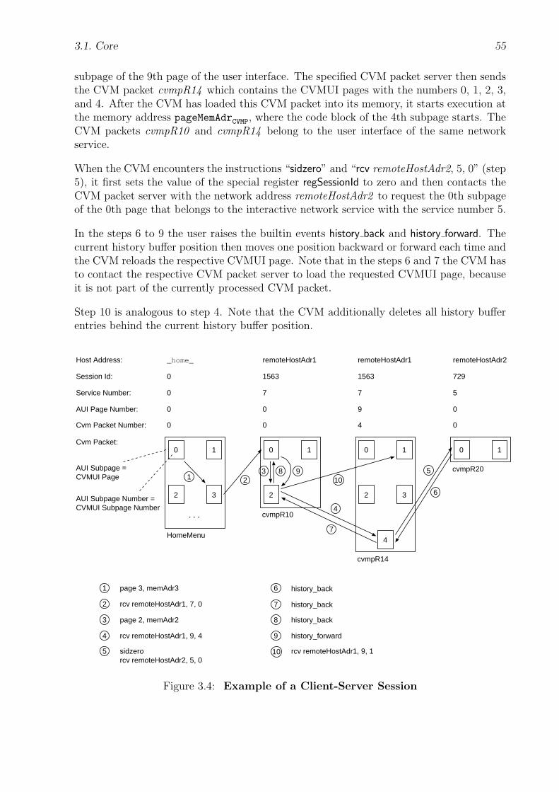
3.1. Core 55
subpage of the 9th page of the user interface. The specified CVM packet server then sendsthe CVM packet cvmpR14 which contains the CVMUI pages with the numbers 0, 1, 2, 3,and 4. After the CVM has loaded this CVM packet into its memory, it starts execution atthe memory address pageMemAdrCVMP, where the code block of the 4th subpage starts. TheCVM packets cvmpR10 and cvmpR14 belong to the user interface of the same networkservice.
When the CVM encounters the instructions “sidzero” and “rcv remoteHostAdr2, 5, 0” (step5), it first sets the value of the special register regSessionId to zero and then contacts theCVM packet server with the network address remoteHostAdr2 to request the 0th subpageof the 0th page that belongs to the interactive network service with the service number 5.
In the steps 6 to 9 the user raises the builtin events history back and history forward. Thecurrent history buffer position then moves one position backward or forward each time andthe CVM reloads the respective CVMUI page. Note that in the steps 6 and 7 the CVM hasto contact the respective CVM packet server to load the requested CVMUI page, becauseit is not part of the currently processed CVM packet.
Step 10 is analogous to step 4. Note that the CVM additionally deletes all history bufferentries behind the current history buffer position.
remoteHostAdr1 remoteHostAdr1_home_Host Address:
Cvm Packet Number: 0 0 4
Cvm Packet:
...
0
cvmpR10
cvmpR14
1
2 3
0 1
2
0 1
2 3
4HomeMenu
1 23
7
5
6
4
8 9
remoteHostAdr2
0
cvmpR20
0 1
10
Service Number: 0 7 7 5
page 3, memAdr31
rcv remoteHostAdr1, 7, 02
page 2, memAdr23
rcv remoteHostAdr1, 9, 44
sidzerorcv remoteHostAdr2, 5, 0
5
history_back6
history_back7
history_back8
history_forward9
rcv remoteHostAdr1, 9, 110
AUI Page Number: 0 0 9 0
Session Id: 0 1563 1563 729
AUI Subpage Number =CVMUI Subpage Number
AUI Subpage =CVMUI Page
Figure 3.4: Example of a Client-Server Session

56 3. Client Virtual Machine (CVM)
page 3, memAdr31
history_back6
history_back8
history_forward9
(localHostAdr, 0, 0, 0, 0, 0, codeSegmentAdr )HomeMenu
(localHostAdr, 0, 0, 0, 0, 0, codeSegmentAdr )HomeMenu
(localHostAdr, 0, 0, 0, 3, 0, memAdr3 )
(remoteHostAdr1, 1563, 7, 0, 0, 0, pageMemAdr )cvmpR10
(localHostAdr, 0, 0, 0, 0, 0, codeSegmentAdr )HomeMenu
(localHostAdr, 0, 0, 0, 3, 0, memAdr3 )
(remoteHostAdr1, 1563, 7, 0, 2, 0, memAdr2)(remoteHostAdr1, 1563, 7, 0, 0, 0, pageMemAdr )cvmpR10
(localHostAdr, 0, 0, 0, 0, 0, codeSegmentAdr )HomeMenu
(localHostAdr, 0, 0, 0, 3, 0, memAdr3 )
(remoteHostAdr1, 1563, 7, 9, 4, 4, pageMemAdr )cvmpR14
(remoteHostAdr1, 1563, 7, 0, 2, 0, memAdr2)(remoteHostAdr1, 1563, 7, 0, 0, 0, pageMemAdr )cvmpR10
(localHostAdr, 0, 0, 0, 0, 0, codeSegmentAdr )HomeMenu
(localHostAdr, 0, 0, 0, 3, 0, memAdr3 )
(remoteHostAdr2, 729, 5, 0, 0, 0, pageMemAdr )(remoteHostAdr1, 1563, 7, 9, 4, 4, pageMemAdr )cvmpR14
(remoteHostAdr1, 1563, 7, 0, 2, 0, memAdr2)(remoteHostAdr1, 1563, 7, 0, 0, 0, pageMemAdr )cvmpR10
(localHostAdr, 0, 0, 0, 0, 0, codeSegmentAdr )HomeMenu
(localHostAdr, 0, 0, 0, 3, 0, memAdr3 )
rcv remoteHostAdr1, 7, 02
page 2, memAdr23
rcv remoteHostAdr1, 9, 44
sidzerorcv remoteHostAdr2, 5, 0
5
(remoteHostAdr2, 729, 5, 0, 0, 0, pageMemAdr )(remoteHostAdr1, 1563, 7, 9, 4, 4, pageMemAdr )cvmpR14
(remoteHostAdr1, 1563, 7, 0, 2, 0, memAdr2 )(remoteHostAdr1, 1563, 7, 0, 0, 0, pageMemAdr )cvmpR10
(localHostAdr, 0, 0, 0, 0, 0, codeSegmentAdr )HomeMenu
(localHostAdr, 0, 0, 0, 3, 0, memAdr3 )
(remoteHostAdr2, 729, 5, 0, 0, 0, pageMemAdr )(remoteHostAdr1, 1563, 7, 9, 4, 4, pageMemAdr )cvmpR14
(remoteHostAdr1, 1563, 7, 0, 2, 0, memAdr2 )(remoteHostAdr1, 1563, 7, 0, 0, 0, pageMemAdr )cvmpR10
(localHostAdr, 0, 0, 0, 0, 0, codeSegmentAdr )HomeMenu
(localHostAdr, 0, 0, 0, 3, 0, memAdr3 )
history_back7
rcv remoteHostAdr1, 9, 110
(remoteHostAdr2, 729, 5, 0, 0, 0, pageMemAdr )(remoteHostAdr1, 1563, 7, 9, 4, 4, pageMemAdr )cvmpR14
(remoteHostAdr1, 1563, 7, 0, 2, 0, memAdr2)(remoteHostAdr1, 1563, 7, 0, 0, 0, pageMemAdr )cvmpR10
(localHostAdr, 0, 0, 0, 0, 0, codeSegmentAdr )HomeMenu
(localHostAdr, 0, 0, 0, 3, 0, memAdr3 )
(remoteHostAdr2, 729, 5, 0, 0, 0, pageMemAdr )(remoteHostAdr1, 1563, 7, 9, 4, 4, pageMemAdr )cvmpR14
(remoteHostAdr1, 1563, 7, 0, 2, 0, memAdr2)(remoteHostAdr1, 1563, 7, 0, 0, 0, pageMemAdr )cvmpR10
(localHostAdr, 0, 0, 0, 0, 0, codeSegmentAdr )HomeMenu
(localHostAdr, 0, 0, 0, 3, 0, memAdr3 )
(remoteHostAdr1, 1563, 7, 9, 1, 4, pageMemAdr )cvmpR14
(remoteHostAdr1, 1563, 7, 0, 2, 0, memAdr2)(remoteHostAdr1, 1563, 7, 0, 0, 0, pageMemAdr )cvmpR10
(localHostAdr, 0, 0, 0, 0, 0, codeSegmentAdr )HomeMenu
(localHostAdr, 0, 0, 0, 3, 0, memAdr3 )cvmpR20
cvmpR20
cvmpR20
cvmpR20
cvmpR20
Figure 3.5: History Buffer Behavior of an Exemplary Client-Server Session
3.1.8 Bookmarks Menu
The bookmarks menu is optional for a given CVM implementation. Similar to commonbrowsers, the user can store in it the addresses of frequently visited CVMUI pages in orderto retrieve them later conveniently. Naturally, the bookmark entries are not cleared afterthe user switches the CVM off. The maximum number of bookmark entries as well asthe user interface of the bookmarks menu itself is left to the implementors’ choice. Theinternal structure of a bookmarks entry is left to the implementors’ choice, too, but mustcontain at least the following items:
{ Nat1[ ] hostAdr; Nat serviceNo, pageNo }
hostAdr represents the address of the network host where the respective CVM packetcomes from. Whether it is an IP [62] address or a DNS [45] name is left to implementors’
3.1. Core 57
choice. Refer also to the profile item cvmDNSLookup (page 90). If the respective CVMpacket is the HomeMenu, then hostAdr refers to the host name “ home ”. Otherwise,hostAdr refers to the network address of a particular CVM packet server. The array typeNat1[ ] is used for a byte stream of any data.
serviceNo represents the number of an interactive network service that is offered by theCVM packet server with the host address hostAdr. The addressed CVMUI page is partof the user interface that belongs to the interactive network service with the numberserviceNo. The data type Nat is used as a shortcut for the data type Nat<cvmIntLen>.Refer to section 3.1.2 (page 33) for more information on cvmIntLen.
pageNo represents the number of the AUI page.
The builtin event menu bookmarks opens the bookmarks menu. Refer to section 3.1.6.4(page 51) and to the CVM state EventProcessBuiltin in the CVM state transitions in section3.1.10 (page 58) for more information on this event.
3.1.9 Interval Timer
The interval timer component is optional for the CVM. Its purpose is to provide an in-terrupt mechanism that is controlled periodically. The interval timer provides millisecondaccuracy. When active, it runs over and over again, sending a signal each time it expires.For example, the interval timer might be used to manage several execution threads that arepart of the same CVM program and run concurrently. In the following, the special intervaltimer registers are described. Refer also to section 3.1.10 (page 58) for more details on theinterval timer concept, CVM states, and the overall state behavior of the CVM.
regTimerSignal The special register regTimerSignal contains a flag bit with the possiblevalues 0 (”unset”) and 1 (”set”). Whenever the time period that is given by the specialregister regTimerInterval expires, the timer sets the value of this register to 1. On theother hand, the CVM automatically unsets this register each time it checks its value. TheCVM checks the value of this register in the states Execute, EventExecute, and Wait, i.e.,regState = Execute ∨ EventExecute ∨ Wait. This register cannot be modified by the CVMinstructions. The initial value of this register is zero.
regTimerHandleAdr The special register regTimerHandleAdr stores the absolute memoryaddress, a Nat value, of the first instruction of the timer handle code block in memory. Thetimer handle code block is a part of the loaded CVM program (and packet). Each time theCVM notices that the interval timer has expired, the CVM interrupts its current activityand jumps to that code block to continue execution there. The instruction settimerhandleadrsets the value of this register. The initial value of this register is zero.
regTimerInterval The special register regTimerInterval stores a Nat value that defines thetime period in milliseconds. If the value is zero, the timer function is deactivated, otherwiseactivated. The instruction settimerinterval sets the value of this register. The initial valueof this register is zero.
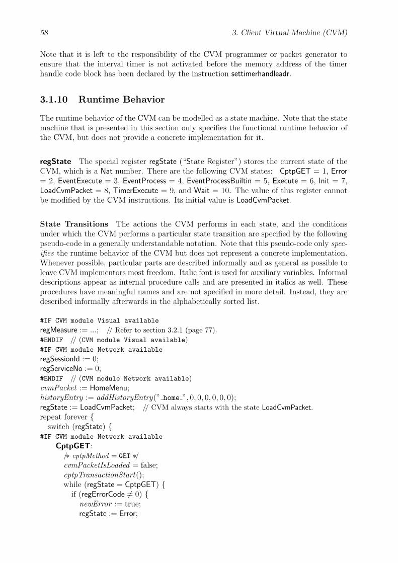
58 3. Client Virtual Machine (CVM)
Note that it is left to the responsibility of the CVM programmer or packet generator toensure that the interval timer is not activated before the memory address of the timerhandle code block has been declared by the instruction settimerhandleadr.
3.1.10 Runtime Behavior
The runtime behavior of the CVM can be modelled as a state machine. Note that the statemachine that is presented in this section only specifies the functional runtime behavior ofthe CVM, but does not provide a concrete implementation for it.
regState The special register regState (“State Register”) stores the current state of theCVM, which is a Nat number. There are the following CVM states: CptpGET = 1, Error= 2, EventExecute = 3, EventProcess = 4, EventProcessBuiltin = 5, Execute = 6, Init = 7,LoadCvmPacket = 8, TimerExecute = 9, and Wait = 10. The value of this register cannotbe modified by the CVM instructions. Its initial value is LoadCvmPacket.
State Transitions The actions the CVM performs in each state, and the conditionsunder which the CVM performs a particular state transition are specified by the followingpseudo-code in a generally understandable notation. Note that this pseudo-code only spec-ifies the runtime behavior of the CVM but does not represent a concrete implementation.Whenever possible, particular parts are described informally and as general as possible toleave CVM implementors most freedom. Italic font is used for auxiliary variables. Informaldescriptions appear as internal procedure calls and are presented in italics as well. Theseprocedures have meaningful names and are not specified in more detail. Instead, they aredescribed informally afterwards in the alphabetically sorted list.
#IF CVM module Visual available
regMeasure := ...; // Refer to section 3.2.1 (page 77).#ENDIF // (CVM module Visual available)#IF CVM module Network available
regSessionId := 0;regServiceNo := 0;#ENDIF // (CVM module Network available)cvmPacket := HomeMenu;historyEntry := addHistoryEntry(” home ”, 0, 0, 0, 0, 0, 0);regState := LoadCvmPacket; // CVM always starts with the state LoadCvmPacket.repeat forever {
switch (regState) {#IF CVM module Network available
CptpGET:/∗ cptpMethod = GET ∗/cvmPacketIsLoaded = false;cptpTransactionStart();while (regState = CptpGET) {
if (regErrorCode 6= 0) {newError := true;regState := Error;
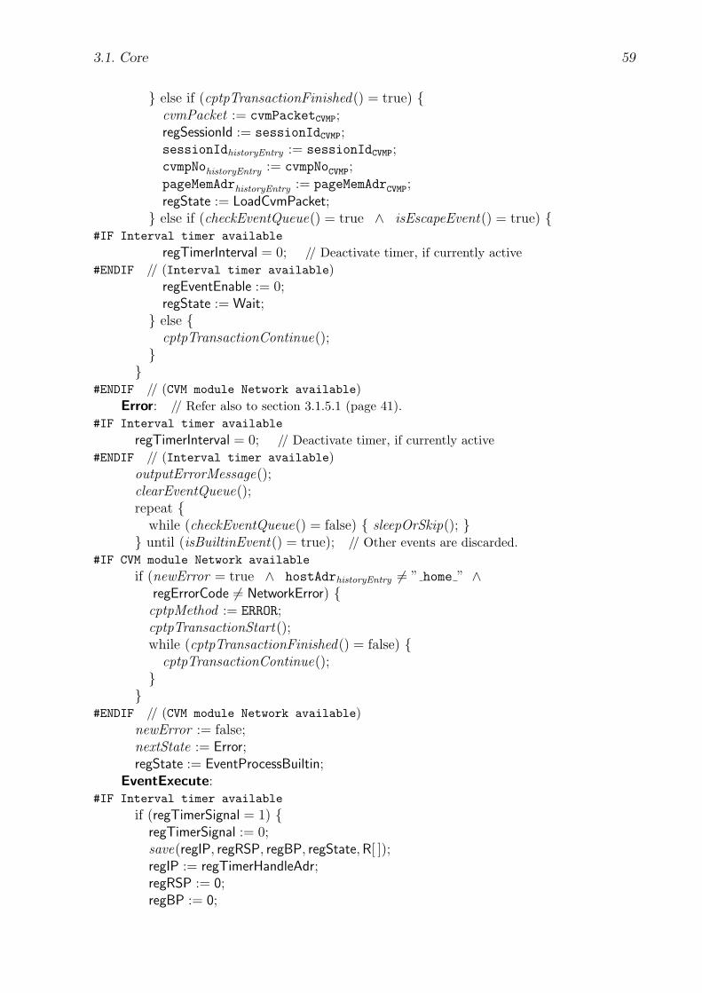
3.1. Core 59
} else if (cptpTransactionFinished() = true) {cvmPacket := cvmPacketCVMP;regSessionId := sessionIdCVMP;sessionIdhistoryEntry := sessionIdCVMP;cvmpNohistoryEntry := cvmpNoCVMP;pageMemAdrhistoryEntry := pageMemAdrCVMP;regState := LoadCvmPacket;} else if (checkEventQueue() = true ∧ isEscapeEvent() = true) {
#IF Interval timer available
regTimerInterval = 0; // Deactivate timer, if currently active#ENDIF // (Interval timer available)
regEventEnable := 0;regState := Wait;} else {
cptpTransactionContinue();}}
#ENDIF // (CVM module Network available)Error: // Refer also to section 3.1.5.1 (page 41).
#IF Interval timer available
regTimerInterval = 0; // Deactivate timer, if currently active#ENDIF // (Interval timer available)
outputErrorMessage();clearEventQueue();repeat {
while (checkEventQueue() = false) { sleepOrSkip(); }} until (isBuiltinEvent() = true); // Other events are discarded.
#IF CVM module Network available
if (newError = true ∧ hostAdrhistoryEntry 6= ” home ” ∧regErrorCode 6= NetworkError) {
cptpMethod := ERROR;cptpTransactionStart();while (cptpTransactionFinished() = false) {
cptpTransactionContinue();}}
#ENDIF // (CVM module Network available)newError := false;nextState := Error;regState := EventProcessBuiltin;
EventExecute:#IF Interval timer available
if (regTimerSignal = 1) {regTimerSignal := 0;save(regIP, regRSP, regBP, regState,R[ ]);regIP := regTimerHandleAdr;regRSP := 0;regBP := 0;

60 3. Client Virtual Machine (CVM)
regState := TimerExecute;break;}
#ENDIF // (Interval timer available)checkInstruction();if (regErrorCode 6= 0) /∗ Error code depends on each instruction. ∗/ {
newError := true;regState := Error;break;}if (opcodeinstruction = halt) {
restore(regIP, regRSP, regBP, regState,R[ ]);/∗ regState ∈ {Execute, Wait} ∗/} else if (opcodeinstruction = page) {
historyEntry := addHistoryEntry(hostAdrhistoryEntry , sessionIdhistoryEntry ,serviceNohistoryEntry , pageNohistoryEntry , subpageNopage,cvmpNohistoryEntry , regIP + pageMemAdrRelpage);
regState := Init;}
#IF CVM module Network available
else if (opcodeinstruction = rcv ∨ opcodeinstruction = sendrcv) {readHostAdrFromMemAt(hostAdrMemAdr<rcv | sendrcv>, cptpHostAdr);if (regErrorCode 6= 0) {
// regErrorCode ∈ {IllegalMemoryAddress, NoDNSLookup}newError := true;regState := Error;break;}cptpMethod := GET;if (regSessionId = 0) {
regServiceNo := pageOrServiceNo<rcv|sendrcv>;cptpPageNo := 0;cptpSubpageNo := 0;} else {
cptpPageNo := pageOrServiceNo<rcv|sendrcv>;cptpSubpageNo := subpageNo<rcv|sendrcv>;}if (opcodeinstruction = rcv) {
cptpNumBytes := 0;cptpDataBytesMemAdr := 0;} else {
cptpNumBytes := numBytes sendrcv;cptpDataBytesMemAdr := dataBytesMemAdr sendrcv;}historyEntry := addHistoryEntry(cptpHostAdr , regSessionId, regServiceNo,
cptpPageNo, cptpSubpageNo, 0, 0);regState := CptpGET;}
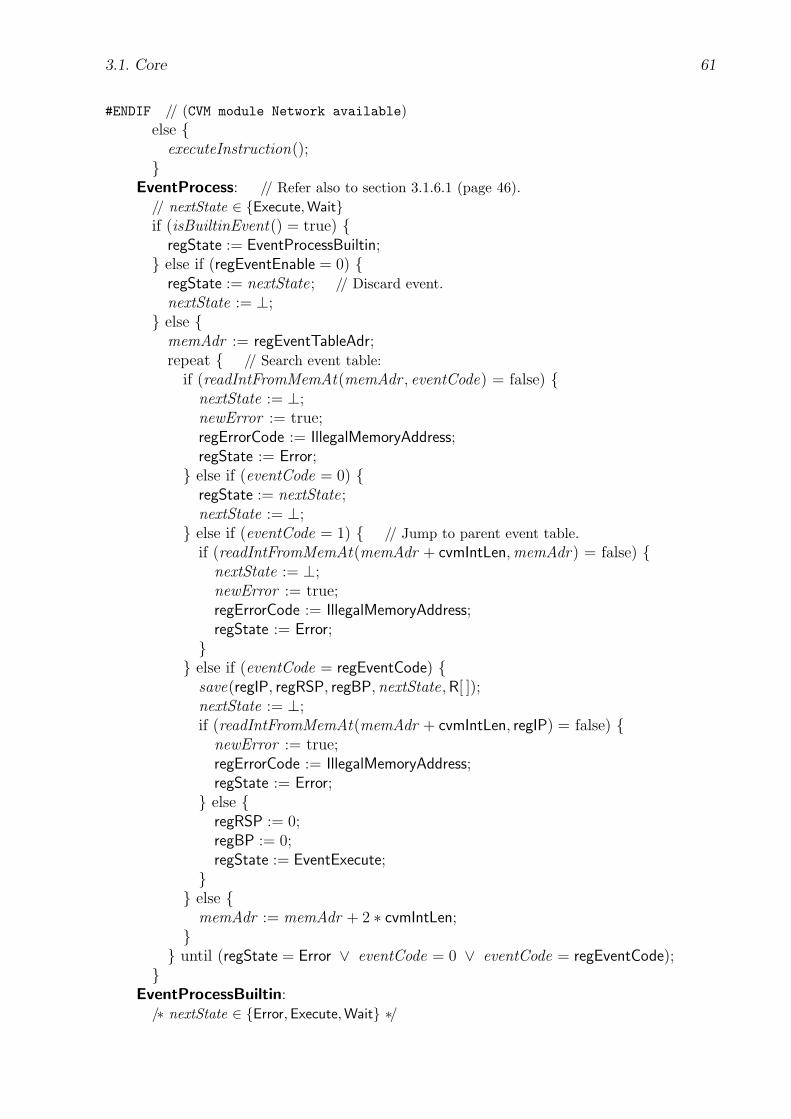
3.1. Core 61
#ENDIF // (CVM module Network available)else {
executeInstruction();}
EventProcess: // Refer also to section 3.1.6.1 (page 46).// nextState ∈ {Execute, Wait}if (isBuiltinEvent() = true) {
regState := EventProcessBuiltin;} else if (regEventEnable = 0) {
regState := nextState; // Discard event.nextState := ⊥;} else {
memAdr := regEventTableAdr;repeat { // Search event table:
if (readIntFromMemAt(memAdr , eventCode) = false) {nextState := ⊥;newError := true;regErrorCode := IllegalMemoryAddress;regState := Error;} else if (eventCode = 0) {
regState := nextState;nextState := ⊥;} else if (eventCode = 1) { // Jump to parent event table.
if (readIntFromMemAt(memAdr + cvmIntLen,memAdr) = false) {nextState := ⊥;newError := true;regErrorCode := IllegalMemoryAddress;regState := Error;}} else if (eventCode = regEventCode) {
save(regIP, regRSP, regBP, nextState,R[ ]);nextState := ⊥;if (readIntFromMemAt(memAdr + cvmIntLen, regIP) = false) {
newError := true;regErrorCode := IllegalMemoryAddress;regState := Error;} else {
regRSP := 0;regBP := 0;regState := EventExecute;}} else {
memAdr := memAdr + 2 ∗ cvmIntLen;}} until (regState = Error ∨ eventCode = 0 ∨ eventCode = regEventCode);}
EventProcessBuiltin:/∗ nextState ∈ {Error, Execute, Wait} ∗/

62 3. Client Virtual Machine (CVM)
if (regEventCode = cvm quit) {turnOffCVM ();} else if (regEventCode = history back ∨
regEventCode = history forward) {historyEntryTmp := historyEntry ;if (setHistoryPosition(historyEntry) = true) {
nextState := ⊥;regErrorCode := 0;if (hostAdrhistoryEntry = ” home ”) {
if (hostAdrhistoryEntryTmp = ” home ” ∧cvmPacketIsLoaded = true) {
regState := Init;} else {
cvmPacket := HomeMenu;regSessionId := sessionIdhistoryEntry ;regServiceNo := serviceNohistoryEntry ;regState := LoadCvmPacket;}}
#IF CVM module Network available
else if (hostAdrhistoryEntry = hostAdrhistoryEntryTmp ∧sessionIdhistoryEntry = sessionIdhistoryEntryTmp ∧pageNohistoryEntry = pageNohistoryEntryTmp ∧cvmpNohistoryEntry = cvmpNohistoryEntryTmp ∧cvmPacketIsLoaded = true) {
regState := Init;} else {
regSessionId := sessionIdhistoryEntry ;regServiceNo := serviceNohistoryEntry ;cptpMethod := GET;cptpHostAdr := hostAdrhistoryEntry ;cptpPageNo := pageNohistoryEntry ;cptpSubpageNo := subpageNohistoryEntry ;cptpNumBytes := 0;cptpDataBytesMemAdr := 0;regState := CptpGET;}
#ENDIF // (CVM module Network available)} else {
regState := nextState;nextState := ⊥;}} else if (regEventCode = history reload) {
nextState := ⊥;regErrorCode := 0;
#IF CVM module Network available
if (hostAdrhistoryEntry 6= ” home ”) {cptpMethod := GET;

3.1. Core 63
cptpHostAdr := hostAdrhistoryEntry ;cptpPageNo := pageNohistoryEntry ;cptpSubpageNo := subpageNohistoryEntry ;cptpNumBytes := 0;cptpDataBytesMemAdr := 0;regState := CptpGET;} else {
#ENDIF // (CVM module Network available)regState := LoadCvmPacket;}
#IF CVM module Network available
}#ENDIF // (CVM module Network available)#IF CVM module Network available
else if (regEventCode = input hostAdr) {openInputHostAdrAndServiceNoUI ();repeat {
while (checkEventQueue() = false) { sleepOrSkip(); }if (isInputHostAdrAndServiceNoEvent() = true) {
doInputHostAdrAndServiceNoAction();}} until (isAcknowledgeEvent() = true ∨ isEscapeEvent() = true)closeInputHostAdrAndServiceNoUI ();if (isEscapeEvent() = true) {
regState := nextState;nextState := ⊥;} else { // isAcknowledgeEvent() = true
nextState := ⊥;regErrorCode := 0;regSessionId := 0;regServiceNo := inputServiceNo;historyEntry := addHistoryEntry(inputHostAdr , regSessionId, regServiceNo,
0, 0, 0, 0);if (inputHostAdr = ” home ”) { // regServiceNo = 0
cvmPacket := HomeMenu;regState := LoadCvmPacket;} else {
cptpMethod := GET;cptpHostAdr := hostAdrhistoryEntry ;cptpPageNo := pageNohistoryEntry ;cptpSubpageNo := subpageNohistoryEntry ;cptpNumBytes := 0;cptpDataBytesMemAdr := 0;regState := CptpGET;}}}
#ENDIF // (CVM module Network available)

64 3. Client Virtual Machine (CVM)
#IF Bookmarks available
else if (regEventCode = menu bookmarks) {openBookmarksMenu();repeat {
while (checkEventQueue() = false) { sleepOrSkip(); }if (isBookmarksEvent() = true) { doBookmarksAction(); }} until (isBookmarksEventFinished() = true);closeBookmarksMenu();if (bookmarkEntryHasBeenSelected() = false) {
regState := nextState;nextState := ⊥;} else {
nextState := ⊥;regErrorCode := 0;
#IF CVM module Network available
regSessionId := 0;regServiceNo := serviceNobookmarksEntry ;
#ENDIF // (CVM module Network available)historyEntry := addHistoryEntry(hostAdrbookmarksEntry , regSessionId,
regServiceNo, pageNobookmarksEntry , 0, 0, 0);#IF CVM module Network available
if (hostAdrhistoryEntry = ” home ”) {#ENDIF // (CVM module Network available)
cvmPacket := HomeMenu;regState := LoadCvmPacket;}
#IF CVM module Network available
else {cptpMethod := GET;cptpHostAdr := hostAdrhistoryEntry ;cptpPageNo := pageNohistoryEntry ;cptpSubpageNo := 0;cptpNumBytes := 0;cptpDataBytesMemAdr := 0;regState := CptpGET;}}
#ENDIF // (CVM module Network available)}
#ENDIF // (Bookmarks available)else if (regEventCode = menu home) {
cvmPacket := HomeMenu;nextState := ⊥;regErrorCode := 0;
#IF CVM module Network available
regSessionId := 0;regServiceNo := 0;
#ENDIF // (CVM module Network available)
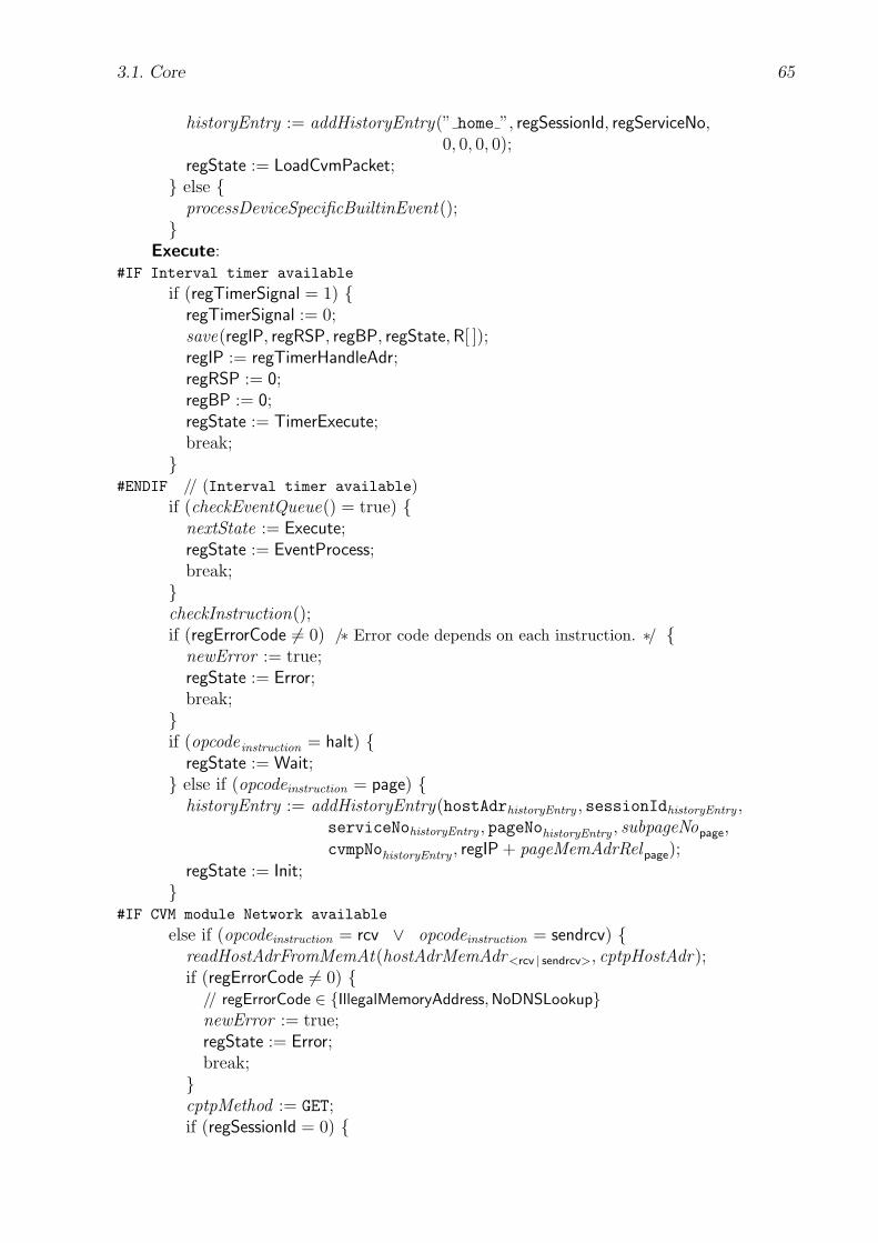
3.1. Core 65
historyEntry := addHistoryEntry(” home ”, regSessionId, regServiceNo,0, 0, 0, 0);
regState := LoadCvmPacket;} else {
processDeviceSpecificBuiltinEvent();}
Execute:#IF Interval timer available
if (regTimerSignal = 1) {regTimerSignal := 0;save(regIP, regRSP, regBP, regState,R[ ]);regIP := regTimerHandleAdr;regRSP := 0;regBP := 0;regState := TimerExecute;break;}
#ENDIF // (Interval timer available)if (checkEventQueue() = true) {
nextState := Execute;regState := EventProcess;break;}checkInstruction();if (regErrorCode 6= 0) /∗ Error code depends on each instruction. ∗/ {
newError := true;regState := Error;break;}if (opcode instruction = halt) {
regState := Wait;} else if (opcodeinstruction = page) {
historyEntry := addHistoryEntry(hostAdrhistoryEntry , sessionIdhistoryEntry ,serviceNohistoryEntry , pageNohistoryEntry , subpageNopage,cvmpNohistoryEntry , regIP + pageMemAdrRelpage);
regState := Init;}
#IF CVM module Network available
else if (opcodeinstruction = rcv ∨ opcodeinstruction = sendrcv) {readHostAdrFromMemAt(hostAdrMemAdr<rcv | sendrcv>, cptpHostAdr);if (regErrorCode 6= 0) {
// regErrorCode ∈ {IllegalMemoryAddress, NoDNSLookup}newError := true;regState := Error;break;}cptpMethod := GET;if (regSessionId = 0) {

66 3. Client Virtual Machine (CVM)
regServiceNo := pageOrServiceNo<rcv|sendrcv>;cptpPageNo := 0;cptpSubpageNo := 0;} else {
cptpPageNo := pageOrServiceNo<rcv|sendrcv>;cptpSubpageNo := subpageNo<rcv|sendrcv>;}if (opcodeinstruction = rcv) {
cptpNumBytes := 0;cptpDataBytesMemAdr := 0;} else {
cptpNumBytes := numBytes sendrcv;cptpDataBytesMemAdr := dataBytesMemAdr sendrcv;}historyEntry := addHistoryEntry(cptpHostAdr , regSessionId, regServiceNo,
cptpPageNo, cptpSubpageNo, 0, 0);regState := CptpGET;}
#ENDIF // (CVM module Network available)else {
executeInstruction();}
Init:regIP := pageMemAdrhistoryEntry ;regRSP := 0;regSS := stackSegmentAdrcvmPacket ;regSP := regSS;regBP := 0;regErrorCode := 0;regEventEnable := 0;regEventCode := 0;regEventTableAdr := 0;
#IF Interval timer available
regTimerHandleAdr := 0;regTimerInterval := 0;regTimerSignal := 0;
#ENDIF // (Interval timer available)#IF CVM module Visual available
regClipX := 0; regClipY := 0;#IF regMeasure = 0
regClipWidth := cvmScreenWidth;regClipHeight := cvmScreenHeight;regLineWidth := 1;
#ELSE // (regMeasure = 0)regClipWidth := cvmScreenWidthMM;regClipHeight := cvmScreenHeightMM;regLineWidth := ...; // ≈ 1pt
#ENDIF // (regMeasure = 0)
3.1. Core 67
regColorRed := 0; regColorGreen := 0; regColorBlue := 0;regBgColorRed := 255; regBgColorGreen := 255; regBgColorBlue := 255;regFontCode := fontFixedStandard; regFontSize := 13;regHTextLine := 0; regXTextLine := 0;clearScreen();
#ENDIF // (CVM module Visual available)#IF CVM module Mouse available
regMouseFont = XC top left arrow;#ENDIF // (CVM module Mouse available)
clearEventQueue();regState := Execute;
LoadCvmPacket:if (loadCvmPacketIntoMem() = true) {
cvmPacketIsLoaded := true;if (hostAdrhistoryEntry = ” home ” ∧
pageNohistoryEntry = 0 ∧ subpageNohistoryEntry = 0) {pageMemAdrhistoryEntry := codeSegmentAdrcvmPacket ;}regState := Init;} else {
cvmPacketIsLoaded := false;newError := true;if (hostAdrhistoryEntry = ” home ”) {
regErrorCode := MalformedHomeMenu;} else {
regErrorCode := MalformedCVMPacket;}regState := Error;}
#IF Interval timer available
TimerExecute:checkInstruction();if (regErrorCode 6= 0) /∗ Error code depends on each instruction. ∗/ {
newError := true;regState := Error;break;}if (opcodeinstruction = halt) {
restore(regIP, regRSP, regBP, regState,R[ ]);/∗ regState ∈ {EventExecute, Execute, Wait} ∗/} else if (opcodeinstruction = page) {
historyEntry := addHistoryEntry(hostAdrhistoryEntry , sessionIdhistoryEntry ,serviceNohistoryEntry , pageNohistoryEntry , subpageNopage,cvmpNohistoryEntry , regIP + pageMemAdrRelpage);
regState := Init;}
#IF CVM module Network available
else if (opcodeinstruction = rcv ∨ opcodeinstruction = sendrcv) {

68 3. Client Virtual Machine (CVM)
readHostAdrFromMemAt(hostAdrMemAdr<rcv | sendrcv>, cptpHostAdr);if (regErrorCode 6= 0) {
// regErrorCode ∈ {IllegalMemoryAddress, NoDNSLookup}newError := true;regState := Error;break;}cptpMethod := GET;if (regSessionId = 0) {
regServiceNo := pageOrServiceNo<rcv|sendrcv>;cptpPageNo := 0;cptpSubpageNo := 0;} else {
cptpPageNo := pageOrServiceNo<rcv|sendrcv>;cptpSubpageNo := subpageNo<rcv|sendrcv>;}if (opcodeinstruction = rcv) {
cptpNumBytes := 0;cptpDataBytesMemAdr := 0;} else {
cptpNumBytes := numBytes sendrcv;cptpDataBytesMemAdr := dataBytesMemAdr sendrcv;}historyEntry := addHistoryEntry(cptpHostAdr , regSessionId, regServiceNo,
cptpPageNo, cptpSubpageNo, 0, 0);regState := CptpGET;}
#ENDIF // (CVM module Network available)else {
executeInstruction();}
#ENDIF // (Interval timer available)Wait:
#IF Interval timer available
if (regTimerSignal = 1) {regTimerSignal := 0;save(regIP, regRSP, regBP, regState,R[ ]);regIP := regTimerHandleAdr;regRSP := 0;regBP := 0;regState := TimerExecute;break;}
#ENDIF // (Interval timer available)if (checkEventQueue() = true) {
nextState := Wait;regState := EventProcess;break;
3.1. Core 69
}sleepOrSkip();
} // End of switch block} // End of repeat block
Comments:
• #IF condition
pseudo-code1
#ELSE
pseudo-code2
#ENDIF
groups conditional parts of the pseudo-code. The condition is expressed informally.If the condition is true, then the pseudo-code1 is inserted at this place, otherwisethe pseudo-code2. The #ELSE part is optional and is omitted, if pseudo-code2 is empty.
• addHistoryEntry(hostAdr , sessionId , serviceNo, pageNo, subpageNo, cvmpNo, page-MemAdr) creates a new entry in the history buffer and returns it. The componentsof the entry are given by the parameters hostAdr, sessionId, serviceNo, pageNo,subpageNo, cvmpNo, and pageMemAdr. The new history entry is always insertedbehind the current history position and the current history position is then set tothe new entry. The other entries behind the new entry are deleted, if available. Ifthe history buffer is already full, then the first entry is deleted before the new entryis inserted behind the current history position. If the maximum size of the historybuffer is only one, then the old entry is simply replaced by the new one. If the historyentry of the current history position has the same hostAdr, sessionId, pageNo, andsubpageNo, then no new history entry is created and the current history entry isreturned. Refer to section 3.1.7 (page 52) for more information on the history buffer.
• bookmarkEntryHasBeenSelected() returns true, if the user has previously selected abookmark entry to be accessed, otherwise false.
• checkEventQueue() returns true, if the event queue is not empty, otherwise false. Ifthe event queue is not empty, it removes the first event from the event queue and setsthe event registers regEventCode and regEventPar<1|2|3> with the appropriate valuesof that event. As already said, events are buffered in an event queue in the FIFO(First In, First Out) manner. Note that a new event can occur and be appendedinto the event queue at any time in any state. However, the CVM checks the eventqueue only in the states Error, EventProcessBuiltin, Execute, CptpGET, and Wait. Inaddition, the CVM checks here in the state Execute every time for a new event.However, this frequency is not necessary in a given implementation provided thatergonomic event handling is ensured for the user.
• checkInstruction() checks whether the execution of the current instruction mightcause an error. The memory address of the current instruction is given by the in-struction pointer register regIP. If an error might occur, the special error registerregErrorCode is automatically set to the appropriate error code value that dependson the instruction. Refer to section 3.1.5.2 (page 42) for a list of all error codes. The

70 3. Client Virtual Machine (CVM)
instruction reference in section 3.9.2 (page 100) describes for each instruction whicherrors might occur.
• clearEventQueue() removes all events from the event queue and discards them.
• clearScreen() fills the whole visual drawing area with the default background color,which is white. Refer also to section 3.2.1 (page 76).
• closeBookmarksMenu() closes the bookmarks menu that has previously been openedby openBookmarksMenu(). If the bookmarks menu has been displayed on the screen,the screen sections that have been obscured by the bookmarks menu are restoredwith their original contents.
• closeInputHostAdrAndServiceNoUI () closes the input host address user interface thathas previously been opened by openInputHostAdrAndServiceNoUI (). If this userinterface has been displayed on the screen, the screen sections that have been obscuredby that user interface, are restored with their original contents.
• cptpMethod, cptpHostAdr, cptpPageNo, cptpSubpageNo, cptpNumBytes, cptpData-BytesMemAdr are variables for building up CPTP transactions. In general, thesevariables are set before the CVM enters the state stateCptpGET. Refer to section 4(page 127) for more information on the CPTP protocol. It depends on the protocolmethod (cptpMethod) which of these variables are needed for a CPTP transaction,whereas cptpMethod and cptpHostAdr are always needed. If the protocol method isGET, the variables cptpPageNo, cptpSubpageNo, cptpNumBytes, and cptpDataBytes-MemAdr are needed as well. Refer also to the instructions rcv (page 108) and sendrcv(page 110).
• cptpTransactionStart() starts a CPTP transaction with a CVM packet server. TheCPTP protocol method is given by the variable cptpMethod. The host address of theCVM packet server is given by the variable cptpHostAdr. If the value of cptpMethodis ERROR, then cptpHostAdr refers to the CVM packet server from which the currentlyprocessed or executed CVM packet comes from. Refer also to the comments on thevariables cptpMethod, cptpHostAdr, etc., in this section and to the CPTP protocolmethods ERROR and GET in section 4.2 (page 129).
Note that the amount of data that the CVM sends to and/or receives from the CVMpacket server at a time is left to the implementors’ choice. However, the user shouldbe able to interrupt and stop the transaction with an escape event. If an error occursduring the transaction, the special error register regErrorCode is set automaticallywith the appropriate error code. However, if the protocol method is ERROR, then anerror during the transaction, e.g., NetworkError (page 43), can be ignored silently bythe CVM.
It is left to the implementors’ choice whether a mechanism for local caching of CVMUIpages is implemented or not. If yes, then cptpTransactionStart() first checks thelocal cache, if it already contains the requested CVMUI page. It only starts a CPTPtransaction with a CVM packet server, if the CVM does not have a valid copy in itslocal cache.
• cptpTransactionContinue() resumes the previously started and still ongoing CPTPtransaction. As already said, the amount of data that the CVM sends to and/or

3.1. Core 71
receives from the CVM packet server at a time is left to the implementors’ choice. Inaddition, each time, the CVM receives a CPTP message from a CVM packet server,it stores the value of the received message item sessionId into its special registerregSessionId. Refer to sections 3.4 (page 82) and 4.1 (page 128) for more informationon regSessionId and sessionId, respectively.
• cptpTransmissionFinished() returns true, if the previously started CPTP transactionis finished, i.e., all the relevant data have been sent and/or received by the CVM overthe network. Otherwise, cptpTransmissionFinished() returns false.
• cvmPacket is a variable that refers to the currently processed CVM packet. At thebeginning, it refers to the HomeMenu. The binary format of a CVM packet is specifiedin section 3.8 (page 93).
• cvmPacketIsLoaded is a variable that indicates whether the CVM memory containsa loaded and valid CVM packet that conforms to the current history entry.
• doBookmarksAction() performs the respective actions according to the currently pro-cessed bookmarks event. Among other things, these actions might include the selec-tion, creation, and deletion of a bookmark entry. These actions are implementationdependent and need not be specified here in more detail.
• doInputHostAdrAndServiceNoAction() performs the respective actions according tothe currently processed event that applies to the input host address dialog mask.These actions are implementation dependent and need not be specified here in moredetail. Mainly, these actions might include the input, presentation, and editing of acharacter string that represents the address of a network host and a service number.Whether the address is an IP [62] address and/or a DNS [45] name is left to theimplementors’ choice. Refer also to the profile item cvmDNSLookup (page 90).
• executeInstruction() executes the instruction at the memory address given by the in-struction pointer register regIP and afterwards automatically sets regIP to the mem-ory address of the next instruction. Refer to the instruction reference in section 3.9.2(page 100) for a description of each instruction.
• eventCode is a variable that stores an event code for temporary use. Refer also tothe comments on readIntFromMemAt(memAdr , eventCode).
• historyEntry is a variable that refers to the history entry at the current historyposition.
• historyEntryTmp is a variable that refers to a history entry for temporary use.
• HomeMenu refers to the home menu of the CVM. Refer to section 3.6 (page 86) formore information on the home menu.
• codeSegmentAdrcvmPacket and stackSegmentAdrcvmPacket refer to the CVM packetitems codeSegmentAdr and stackSegmentAdr of the CVM packet cvmPacket. Referto section 3.8 (page 93) for more information on these packet items.
72 3. Client Virtual Machine (CVM)
• <hostAdrMemAdr | subpageNo | pageOrServiceNo | pageMemAdrRel | numBytes |dataBytesMemAdr><page | rcv | sendrcv> each refer to the parameters hostAdrMemAdr,
subpageNo, pageOrServiceNo, pageMemAdrRel, numBytes, and dataBytesMemAdr ofthe CVM instructions page, rcv, and sendrcv, respectively.
• <hostAdr | sessionId | serviceNo | pageNo | subpageNo | cvmpNo |pageMemAdr><historyEntry | historyEntryTmp>
each refer to the hostAdr, sessionId, serviceNo, pageNo, subpageNo, cvmpNo, andpageMemAdr item of an history entry structure, respectively. The variables historyEn-try and historyEntryTmp refer to an history entry structure. Refer also to section3.1.7 (page 52) for more information on the history buffer.
• <hostAdr | serviceNo | pageNo><bookmarksEntry> each refer to the hostAdr, service-No, and pageNo item of a bookmarks entry structure, respectively. The variablebookmarksEntry refers to a bookmarks entry structure. Refer also to section 3.1.8(page 56) for more information on the bookmarks menu.
• inputHostAdr is a variable that refers to the IP [62] address or the DNS [45] name ofa network host. It stems from openInputHostAdrAndServiceNoUI ().
• inputServiceNo is a variable that refers to the number of an interactive networkservice. It stems from openInputHostAdrAndServiceNoUI ().
• isAcknowledgeEvent() returns true, if the values of the special event registers regEvent-Code and regEventPar<1|2|3> indicate an acknowledgment by the user. For exam-ple, this is the case if the CVM has a keyboard and if the value of regEventCode iskey pressed enter. However, if the CVM has a microphone instead, the user mightas well speak something like “Yes” into it. Otherwise, isAcknowledgeEvent() returnsfalse. It is left to the implementors’ choice which user actions cause an acknowledgeevent. However, for reasons of usability they should be self-evident.
• isBookmarksEvent() returns true, if the value of the special event register regEvent-Code matches an event code that applies to the bookmarks menu. These event codescan be chosen freely by the CVM implementor and need not be specified here inmore detail. In addition to the standard event codes, the CVM implementor mightalso add vendor-specific bookmark event codes. However, these must not interferewith the standard CVM event codes, which are listed in section 3.1.6.4 (page 49).Otherwise, isBookmarksEvent() returns false.
• isBookmarksEventFinished() returns true, if the value of the special event regis-ter regEventCode matches an event code that applies to the bookmarks menu, i.e.,isBookmarksEvent() = true, and if that event code indicates that the user wantsto finish the bookmarks menu. These event codes can be chosen freely by the CVMimplementor, e.g., key pressed enter (page 51), key pressed escape (page 51), etc. Oth-erwise, isBookmarksEventFinished() returns false.
• isBuiltinEvent() returns true, if the value of the special event register regEventCodematches the event code of a builtin event. Refer to section 3.1.6.3 (page 49) for moreinformation on builtin events.

3.1. Core 73
• isEscapeEvent() returns true, if the value of the special event registers regEvent-Code and regEventPar<1|2|3> indicate an escape or abort by the user. For example,this is the case if the CVM has a keyboard and if the value of regEventCode iskey pressed escape. However, if the CVM has a microphone instead, the user mightas well speak something like “Stop”, “Escape”, or “Abort” into it. It is left to theimplementors’ choice which user actions cause an escape-event. However, for reasonsof usability they should be self-evident.
• isInputHostAdrAndServiceNoEvent() returns true, if the value of the special eventregister regEventCode matches an event code that applies to the input host addressdialog mask. The set of these events can be chosen freely by the CVM implementorand need not be specified here in more detail. Besides the standard events likekey pressed, other, i.e., non-standard, event codes are also possible. The non-standardevent codes are also implementation dependent and need not be specified here in moredetail. However, they must not interfere with the standard event codes. The standardevent codes are listed in section 3.1.6.4 (page 49).
• loadCvmPacketIntoMem() loads the data and code of the current CVM packet (cvm-Packet) into memory. Refer to section 3.8 (page 93) for more information on theCVM packet format. The current CVM packet might be the HomeMenu or it mighthave been received over the network from a CVM packet server. If the format of theCVM packet is malformed, loadCvmPacketIntoMem() returns false, otherwise true.
Note that the CVM does not clear its memory before it loads a new CVM packetinto memory. This enables incremental download of additional data and code andselective overwriting of specific data and code of the recently executed CVM program.For example, the user might decide during execution of a CVM program, whetheroptional images should be downloaded and embedded into the current CVM programto be displayed.
• memAdr is a variable that stores a memory address for temporary use.
• nextState is a variable that refers to a CVM state. The purpose of this variable is tosave a default state into which the CVM might fall back in the further processing.
• newError is a variable that indicates whether the current error has already beenprocessed in the state Error. If not, then it’s value is true, otherwise false.
• opcodeinstruction refers to the operation code of the currently executed instruction.Refer to the instruction reference in section 3.9.2 (page 100) for a complete list of alloperation codes.
• openBookmarksMenu() presents the bookmarks menu on the output device of theCVM. If the CVM has a screen, it displays a GUI that contains the bookmark entries.If the CVM has no screen, but a speaker, an acoustic version of the bookmarks menuis presented. The appearance of the user interface for the bookmarks menu can bechosen freely by the CVM implementor and need not be specified here in more detail.
• openInputHostAdrAndServiceNoUI () presents a user interface on the output deviceof the CVM in which the user can input the address of a network host (inputHostAdr)and the number (inputServiceNo) of one of its provided interactive network services.
74 3. Client Virtual Machine (CVM)
The appearance of this user interface can be chosen freely by the CVM implementorand need not be specified here in more detail. In the following, this user interface isreferred to with the term input host address dialog mask.
• outputErrorMessage() outputs an error message on the output device to inform theuser. Refer also to section 3.1.5.1 (page 41).
• processDeviceSpecificBuiltinEvent() is implementation dependent and therefore notspecified here in more detail. Refer to section 3.1.6.3 (page 49) for more informationon device specific builtin events.
• readHostAdrFromMemAt (hostAdrMemAdr<rcv | sendrcv>, cptpHostAdr) reads a hostaddress from CVM memory which starts at the memory address hostAdrMemAdrand assigns it to the variable cptpHostAdr. The host address might be a DNS [45]name or an IP address [62] in standard dot notation. It is not checked whether thehost address is valid or not. If the memory is not accessed inside its bounds, whichis given by the interval [0; cvmMemMaxAdr], the special error register regErrorCodeis set to the error code value IllegalMemoryAddress (page 43). If the host address is aDNS name, but the CVM does not support automatic DNS lookup, the special errorregister regErrorCode is set to the error code value NoDNSLookup (page 44). Referalso to the profile item cvmDNSLookup (page 90).
• readIntFromMemAt(memAdr , eventCode) reads an integer (Int<cvmIntLen>) valuefrom the memory at the address memAdr and assigns it to the variable eventCode.If the memory is not accessed inside its bounds, which is given by the interval [0;cvmMemMaxAdr], the return value is false, otherwise true.
• readIntFromMemAt(memAdr + cvmIntLen,memAdr) reads an integer (Int<cvmInt-Len>) value from the memory at the address memAdr + cvmIntLen and assigns itto the variable memAdr. If the memory is not accessed inside its bounds, which isgiven by the interval [0; cvmMemMaxAdr], the return value is false, otherwise true.
• readIntFromMemAt(memAdr , regIP) reads an integer (Int<cvmIntLen>) value fromthe memory at the address memAdr and stores it into the special register regIP.If the memory is not accessed inside its bounds, which is given by the interval [0;cvmMemMaxAdr], the return value is false, otherwise true.
• restore(...) writes the values back into the respective special and general registersthat have been saved previously with save(...).
• save(...) saves the current execution context that is given by the parameters in (...)onto the memory stack or into an internal structure inside the CVM which is notspecified here in more detail, but left to the implementors’ choice.
Note that in the state EventProcess the state nextState is saved instead of the currentstate which is given by the special state register regState. After the CVM finishesevent handling in the state EventExecute and restores the saved execution contextwith restore(...), it loads the previously saved state nextState into regState, i.e., itresumes with the state nextState, which is Execute or Wait.
• <sessionId | cvmpNo | pageMemAdr | cvmPacket>CVMP each refer to the protocol mes-sage items sessionId, cvmpNo, pageMemAdr, and cvmPacket of the CPTP message
3.2. Visual 75
with the protocol method CVMP. Refer to sections 4 (page 127) and 4.2 (page 129) formore information on the CPTP protocol and on the protocol method CVMP.
• setHistoryPosition(historyEntry) moves the current history buffer position to theprevious or next history entry, if the value of the special event register regEventCodematches the event code history back or history forward, respectively. Next, it assignsthe variable historyEntry the history entry that is referred to by the new currenthistory buffer position and returns true. However, if there is no previous or nexthistory entry, respectively, the current history buffer position is not changed andthe variable historyEntry remains unchanged. The return value then is false. Referalso to the builtin events history back (page 50) and history forward (page 50) and tosection 3.1.7 (page 52) for more information on the history buffer.
• sleepOrSkip() is implementation dependent. The following actions are possible: TheCVM may wait until an event or a timer signal occurs. Or the CVM might sleepfor a fixed amount of time. This time period then should be small enough to enablesmooth event and timer interrupt handling. However, the CVM may as well not waitor sleep at all. Then, if sleepOrSkip() appears with checkEventQueue() in a loop, theCVM performs a kind of waiting that is generally known as “busy waiting”.
• turnOffCVM () turns the CVM off.
• XC top left arrow refers to an X11 [52] cursor font name. Refer also to section 3.3(page 82).
• Note that a timer signal can occur in any CVM state. As already said, a timer signalsets the value of the special timer register regTimerSignal to 1. However, the CVMchecks for the value of regTimerSignal only in the states EventExecute, Execute, andWait, i.e., interval timer interrupt handling is performed only in these states. Toensure real-time conformity as much as possible, the CVM code that is executed inthe state TimerExecute should not consume too much time, i.e., its execution timeshould not exceed the time period of the interval timer. Therefore, instructions likercv and sendrcv should be omitted in that CVM state, because in the state CptpGETno interval timer interrupt is handled.
3.2 Visual
The CVM module Visual controls the visual output on the client device’s visual drawingarea of the screen. Mainly, this module covers the basic graphic operations such as drawingelementary graphic shapes, text, and pixel maps, because these tasks occur most often ingraphical user interfaces. The more complicated tasks such as scrolling, affine transfor-mations, and animations as well as the more complex drawing operations such as drawingcubic curves or handling diverse image and multimedia formats like GIF [29], JPEG [39],MPEG [47], etc. are not supported directly by this module. These tasks can be achievedeither explicitly by providing appropriate procedures in the CVM program or by callingappropriate library functions. Refer to section 3.5 (page 83) for more information on thelibrary functions.
76 3. Client Virtual Machine (CVM)
3.2.1 Graphics State
The graphics state includes the current foreground and background colors, the text font,etc. These informations are used by the graphics primitives, i.e., the CVM drawing in-structions, implicitly. As a result, they need not be provided as operands for each graphicsprimitive, which reduces network traffic between the CVM packet server and the client.The graphics state is stored in the following special registers:
regColorRed, regColorGreen, regColorBlue The special registers regColorRed, regCol-orGreen, and regColorBlue store with their Nat1 values the red, green, and blue componentsof the current foreground color — according to the 24-bit RGB [70] color model. The fore-ground color for drawing shapes and writing text onto the screen is defined by these threeregisters and used by all graphics primitives implicitly. The foreground color representsthe drawing color. Most drawing instructions only draw with the foreground color in theforeground and leave the background untouched. The initial value of each register is zero,which corresponds to the black color. The values of these registers are modified by theinstructions setred, setgreen, setblue, setcolor, and setcolor32.
Note that a given CVM implementation need not be able to display 24-bit RGB colors.How the CVM approximates these colors and whether it uses internal colormaps is left tothe implementors’ choice.
regBgColorRed, regBgColorGreen, regBgColorBlue The special registers regBgCol-orRed, regBgColorGreen, and regBgColorBlue store with their Nat1 values the red, green,and blue components of the current background color — according to the 24-bit RGB [70]color model. The background color is only used by the drawing instructions bitmapbg,textbg, textbgl, textbglm, textbgm. These instructions draw their graphic shapes with theforeground color and fill the background area of the bounding box of the respective shapewith the background color, respectively. The initial value of each register is 255, which cor-responds to the white color. The values of these registers are modified by the instructionssetbgred, setbggreen, setbgblue, setbgcolor, and setbgcolor32.
regClipX, regClipY, regClipWidth, regClipHeight The special registers regClipX, reg-ClipY, regClipWidth, and regClipHeight store with their integer values the xy coordinateposition, width, and height of the current rectangular clip area within the screen’s visualdrawing area. Only the pixels inside this clip area are affected in a drawing operation. Themeasuring unit of the xy coordinate system is defined by the special register regMeasure.The initial values of these registers are 0, 0, cvmScreenWidth (or cvmScreenWidthMM),and cvmScreenHeight (or cvmScreenHeightMM), respectively. If the value of regMeasure iszero, cvmScreenWidth and cvmScreenHeight are used, otherwise cvmScreenWidthMM andcvmScreenHeightMM. That is, the initial clip area is the entire visual drawing area of thescreen. Refer to section 3.7 (page 92) for more information on cvmScreenWidth(MM) andcvmScreenHeight(MM). The values of these registers are modified by the instruction setclip(page 112).
regFontCode The special register regFontCode stores with its Nat value the code numberof the current font that is used by all text-drawing graphics primitives. The respective font
3.2. Visual 77
size is given by the special register regFontSize. Refer to section 3.2.3 (page 79) for a listof all font codes. The initial value of this register is fcFixedStandard. The value of thisregister can be modified by the instructions setfontcode, setfont, and setfont32.
regFontSize The special register regFontSize stores with its Nat value the size of thecurrent font. The size is given in pixels, if the value of the special register regMeasure iszero, otherwise in tenths of a Point (pt). The initial value of this register is 13. The valueof this register can be modified by the instructions setfontsize, setfont, and setfont32.
regLineWidth The special register regLineWidth stores with its Nat value the line widththat is used by the drawing instructions for drawing the borders of the elementary graphicshapes such as lines, rectangles, circles, etc. The measuring unit of the line width is definedby the special register regMeasure. If the value of regMeasure is zero, the initial value ofregLineWidth is one, which corresponds to one pixel point. Otherwise, the initial value ofregLineWidth can be chosen freely by the CVM implementor. However, it should be thenapproximately one pt or less, with 1pt = 1/72 inch ≈ 0.3528 mm. pt refers to the BigPoint (or shortly Point) and is widely used as the typographic unit in computer industry.The value of this register can be modified by the instruction setlinewidth.
regMeasure The special register regMeasure defines with its Nat2 value the measuringunit of the xy coordinate system in the visual drawing area. All Visual instructions referto this measuring unit. If its value is zero, a pixel point of the visual drawing area serves asone unit of measure. The measuring unit is then device specific. If the value of regMeasureis greater than zero, one unit of measure is defined by the expression pt/regMeasure, withpt = 1/72 inch ≈ 0.3528 mm. pt refers to the Big Point (or shortly Point) and is widelyused as the typographic unit in computer industry. For example, if the value of regMeasureis 1000, the length of the measuring unit is 1/1000 pt . The measuring unit is then absoluteand platform independent and the client has to perform the rasterization. Whether theclient applies anti-aliasing during rasterization is left to the implementors’ choice.
The coordinates of the upper left corner are (0, 0). Going right or down increases the x ory coordinate, respectively.
The value of regMeasure depends on the CVM implementation and cannot be modified atall. For restricted client devices it will typically be zero. The value is sent by the client tothe server within the CVM profile during a client request. Refer to section 3.7 (page 89)for more information on the CVM profile.
regHTextLine, regXTextLine The special registers regHTextLine and regXTextLine storea Nat and Int value that represents the height of a text line and the x coordinate of thebeginning of a text line, respectively. These values are used by the text drawing instructionstextp, textpm, textpbg, and textpmbg for drawing a text paragraph, which consists of one orseveral lines of text, onto the visual drawing area. The measuring unit of the xy coordinatesystem is defined by the special register regMeasure. The initial values of both registersare zero. The values of these register can be modified by the instructions sethtextline andsetxtextline, respectively.
78 3. Client Virtual Machine (CVM)
3.2.2 Graphics Primitives
The CVM instructions that perform drawing operations are called graphics primitives.However, a graphics primitive only specifies the general shape, i.e., a line, rectangle, circle,text, etc., of a graphic object, whereas the graphics state provides additional informationon the appearance of the graphic object. Therefore, the operands of a graphics primitivemainly concentrate on specifying the shape of the graphic object that is to be drawn.
Note that if a graphics primitive tries to draw beyond the current clip area of the screen,the CVM only draws that part which is inside this clip area. Everything else is clippedautomatically without producing an error.
Elementary Graphic Shapes Elementary graphic shapes for constructing graphicaluser interfaces are horizontal and vertical lines, rectangles, and circles. As already said,these shapes are essential for most graphical user interfaces. In the following, the CVMinstructions for these elementary graphic shapes are introduced. Refer to section 3.9.2(page 100) for a complete reference. The drawing of other graphic shapes like arbitrarylines, quadratic or cubic curves, etc., requires appropriate CVM library functions. Referto section 3.5 (page 83) for more information on the CVM library functions.
Horizontal and Vertical Lines The instructions linehoriz and linevert draw hor-izontal and vertical lines on the screen in the current color, respectively. Horizontal linesare often needed for underlining text. In addition, both horizontal and vertical lines mightbe used for drawing tables and for the visual separation of the drawing area into logicalparts.
Rectangles The instructions rect and rectfill draw and fill rectangles in the currentcolor, respectively. Rectangles are often needed for buttons in user interfaces. rect andrectfill can also be used to draw single pixel points. Then, the width and height values ofthe rectangle must both be set to one.
Circles The instructions circle and circlefill draw and fill circles in the current color,respectively. Circles are often needed for round buttons in user interfaces and for tickmarksin enumeration lists.
Text The instructions text, textm, textp, textpm, textbg, textmbg, textpbg, and textpmbgwrite text on the visual drawing area in the current font and color. The instructions textp,textpm, textpbg, and textpmbg are useful for writing a whole text paragraph, i.e., severalsuccessive lines of text.
Bitmaps The instructions bitmap and bitmapbg draw bitmap images. The image datais located in memory. The format of the bitmap image complies to the X BitMap formatXBM [96]. Bitmaps are often needed for icons. For the rendering of images in the XPM[38], GIF [29], JPEG [39], or other formats and of multimedia content in MPEG [47]format, etc., appropriate CVM library functions are required. Refer to section 3.5 (page83) for more information on the CVM library functions.
3.2. Visual 79
Screen Buffering Sometimes a particular screen section needs to be buffered in memoryand later restored again because it is obscured temporarily by another graphic shape, e.g.,a moving text cursor or a pop-up window. The instruction screen2mem performs thebuffering from screen into memory, whereas the instruction mem2screen restores the screensection by drawing the buffered screen section from memory onto the screen. The formatof the buffered screen section in memory is internal for the given CVM implementation.However, each pixel value may take at most three bytes. This predefined upper boundaryis necessary, because the CVM programmer or packet generator must reserve enough bytesfor it in the Data section of the CVM memory.
3.2.3 Fonts
There are a lot of different fonts from different font providers like Adobe [3], TrueType[85], etc., available. Unfortunately, there is neither a well-defined and universally acceptedtaxonomy for classifying all different kinds of fonts nor a standardized unique code numberfor each type of font. The font capabilities of the client devices may vary and naturally arestricted client device cannot be assumed to cope with all existing fonts. As a proof ofconcept, the code numbers of some commonly used pixel-based fonts in X11 [51] are definedhere. The definition of additional fonts and of specific fonts for devices with restricteddisplay capabilities is left as an open issue in this thesis. Besides, CVM library functionsfor managing more complex fonts may be defined in the future and are left as an openissue as well.
In the following, the currently supported font codes are listed using the following descriptionformat:
font code name = font code: pixel sizes ; tenth point sizesX11 font descriptor name
The font code name represents the mnemonic of the font code and can be used in a CVMassembler program. The font code is a unique Nat number greater than zero identifyinga particular font type. pixel sizes is a comma separated list of positive integer numbersthat contains the legal sizes of the respective font in pixels. tenth point sizes is a commaseparated list of positive integer numbers that contains the legal sizes of the respectivefont in tenths of a Point (pt). If the special register regFontCode of a given CVM containsa particular font code value, the special register regFontSize can only contain one of therespective values. Whether the font size is given in pixels or tenths of a point, dependson the value of the special register regMeasure. The unit is assumed to be a pixel, if thevalue of regMeasure is zero, otherwise a tenth of a Point. The X11 font descriptor namespecifies the font by using the X11 terminology XLFD [50, 51].
• fcFixedStandard = 1: 13; 120-misc-fixed-medium-r-semicondensed--*-*-75-75-c-60-iso8859-*
• fcFixedStandardBold = 2: 13; 120-misc-fixed-bold-r-semicondensed--*-*-75-75-c-60-iso8859-*
• fcFixedStandardItalic = 3: 13; 120-misc-fixed-medium-o-semicondensed--*-*-75-75-c-60-iso8859-*
80 3. Client Virtual Machine (CVM)
• fcFixed = 4: 6, 8, 10, 13, 15, 20; 60, 80, 100, 120, 140, 200-misc-fixed-medium-r-normal--*-*-75-75-c-*-iso8859-*
• fcFixedBold = 5: 13, 15; 120, 140-misc-fixed-bold-r-normal--*-*-75-75-c-*-iso8859-*
• fcFixedItalic = 6: 13; 120-misc-fixed-medium-o-normal--13-120-75-75-c-70-iso8859-*
• fcCourier = 7: 8, 10, 12, 14, 18, 24; 80, 100, 120, 140, 180, 240-adobe-courier-medium-r-normal--*-*-75-75-m-*-iso8859-*
• fcCourierBold = 8: 8, 10, 12, 14, 18, 24; 80, 100, 120, 140, 180, 240-adobe-courier-bold-r-normal--*-*-75-75-m-*-iso8859-*
• fcCourierItalic = 9: 8, 10, 12, 14, 18, 24; 80, 100, 120, 140, 180, 240-adobe-courier-medium-o-normal--*-*-75-75-m-*-iso8859-*
• fcCourierBoldItalic = 10: 8, 10, 12, 14, 18, 24; 80, 100, 120, 140, 180, 240-adobe-courier-bold-o-normal--*-*-75-75-m-*-iso8859-*
• fcHelvetica = 11: 8, 10, 12, 14, 18, 24; 80, 100, 120, 140, 180, 240-adobe-helvetica-medium-r-normal--*-*-75-75-p-*-iso8859-*
• fcHelveticaBold = 12: 8, 10, 12, 14, 18, 24; 80, 10, 12, 14, 24-adobe-helvetica-bold-r-normal--*-*-75-75-p-*-iso8859-*
• fcHelveticaItalic = 13: 8, 10, 12, 14, 18, 24-adobe-helvetica-medium-o-normal--*-*-75-75-p-*-iso8859-*
• fcHelveticaBoldItalic = 14: 8, 10, 12, 14, 18, 24-adobe-helvetica-bold-o-normal--*-*-75-75-p-*-iso8859-*
• fcNewCenturySchoolbook = 15: 8, 10, 12, 14, 18, 24; 80, 100, 120, 140, 180, 240-adobe-new century schoolbook-medium-r-normal--*-*-75-75-p-*-iso8859-*
• fcNewCenturySchoolbookBold = 16:8, 10, 12, 14, 18, 24; 80, 100, 120, 140, 180, 240-adobe-new century schoolbook-bold-r-normal--*-*-75-75-p-*-iso8859-*
• fcNewCenturySchoolbookItalic = 17:8, 10, 12, 14, 18, 24; 80, 100, 120, 140, 180, 240-adobe-new century schoolbook-medium-i-normal--*-*-75-75-p-*-iso8859-*
• fcNewCenturySchoolbookBoldItalic = 18:8, 10, 12, 14, 18, 24; 80, 100, 120, 140, 180, 240-adobe-new century schoolbook-bold-i-normal--*-*-75-75-p-*-iso8859-*
• fcTimes = 19: 8, 10, 12, 14, 18, 24; 80, 100, 120, 140, 180, 240-adobe-times-medium-r-normal--*-*-75-75-p-*-iso8859-*
• fcTimesBold = 20: 8, 10, 12, 14, 18, 24; 80, 100, 120, 140, 180, 240-adobe-times-bold-r-normal--*-*-75-75-p-*-iso8859-*

3.3. Keyboard, Mouse 81
• fcTimesItalic = 21: 8, 10, 12, 14, 18, 24; 80, 100, 120, 140, 180, 240-adobe-times-medium-i-normal--*-*-75-75-p-*-iso8859-*
• fcTimesBoldItalic = 22: 8, 10, 12, 14, 18, 24; 80, 100, 120, 140, 180, 240-adobe-times-bold-i-normal--*-*-75-75-p-*-iso8859-*
• fcSymbol = 23: 8, 10, 12, 14, 18, 24; 80, 100, 120, 140, 180, 240-adobe-symbol-medium-r-normal--*-*-75-75-p-*-adobe-fontspecific
The font code fcFixedStandard is supported by every CVM implementation, whereas allother font codes are optional. Refer also to cvmFonts in section 3.7 (page 90).
3.3 Keyboard, Mouse
The CVM modules Keyboard and Mouse are optional in a given CVM implementation.
Keyboard The keyboard may differ from device to device. Smaller devices often haveless keys than customary keyboards for PCs or workstations. In addition, restricted devicesoften have special keys that are not available on customary keyboards, e.g., a button onthe mobile phone to open the address book immediately. Unfortunately, the charactercodes for these special buttons have not been standardized yet. The definition of keyboard(or keypad) layouts and character sets especially suited for restricted client devices is notaddressed in this thesis. Therefore, as a proof of concept, the virtual key code valuesof the X11 type KeySym [50, 51, 52] are used to address the individual keys of the clientdevice’s keyboard. The virtual key codes and their names are defined in the X11 system file<X11/keysymdef.h>. Of course, a given CVM implementation does not need to supportall of them. As far as needed, the special keys are emulated by particular key combinations.
The keyboard events are key pressed, key pressed enter, key pressed released, key released,key released enter, and key released escape. Refer to section 3.1.6.4 (page 51) for moreinformation on these events.
Mouse The positive Nat numbers 1, 2, 3, 4, 5 reflect the left (leftButton), middle(middleButton), right (rightButton), wheel up (wheelUp), and wheel down (wheelDown)mouse buttons, respectively. The names enclosed within the parentheses serve as mnemon-ics and might be used in a CVM assembler program. Note that the wheel up and wheeldown buttons are physically the same wheel button. However, the wheel up button signifiesthat the mouse wheel was rotated up, i.e., away from the user, whereas the wheel downbutton signifies that the mouse wheel was rotated down, i.e., towards the user.
The mouse events are mouse moved, mouse pressed, mouse pressed left, mouse released, andmouse released left. Refer to section 3.1.6.4 (page 52) for more information on these events.
In an application, the mouse may have different graphic shapes on the screen, dependingon its position. For example, if the mouse points into a text box, it often looks like avertical line to symbolize a cursor. However, if it points at a hyperlink, it often looks likea pointing hand. Here, as a proof of concept, the X11 [52] cursor fonts are used for thedifferent mouse shapes. The names and integer code numbers of the X11 cursor fonts aredefined in the X11 system file <X11/cursorfont.h>. The X11 cursor font names can be
82 3. Client Virtual Machine (CVM)
used in the CVM assembler programs. Refer to section B (page 216) for a description ofthe CVM assembler.
Note that the screen section that is obscured by the mouse shape at its current screenposition is restored automatically by the CVM, when the mouse moves to another screenposition.
regMouseFont The special register regMouseFont stores with its Nat value the code num-ber of the current mouse font (or shape). The initial value of this register is 132, whichcorresponds to the X11 cursor font name XC top left arrow. The value of this registercan be modified by the instruction setmousefont.
3.4 Network
For the data transmission over the network a reliable network transport service, likeTCP/IP [69] in the Internet, is assumed. How such a transport service is establishedin mobile, wireless and ad-hoc [61] networks is not addressed in this thesis. Generally, theCVM communicates over the network with a CVM packet server. The used applicationprotocol is CPTP. It runs on top of the transport layer and is a very “thin” counterpartto the HTTP [10] application protocol in the World Wide Web. Refer to section 4 (page127) for more information on CPTP.
The instruction rcv initiates a request for a particular CVMUI page. Then, the addressedCVM packet server sends a CVM packet that contains the requested CVMUI page to theCVM. The instruction sendrcv is similar to the instruction rcv. However, it first sends datato the specified CVM packet server before it requests a particular CVMUI page from thatCVM packet server.
Refer also to the CVM state transitions in section 3.1.10 (page 58), especially to statesEventExecute, EventProcessBuiltin, Execute, CptpGET, and TimerExecute.
Note that if the CVM has not implemented the Network module, it can only execute itsHome Menu. In particular cases this may be sufficient, for example for home devices withonly “local” tasks such as washing machines. However, in the normal case, the Networkmodule is available for a given CVM implementation.
regSessionId The special register regSessionId contains a Nat1[4] value that identifies thecurrent client-server session with a particular CVM packet server. Each time, when theCVM receives a CPTP message from a CVM packet server, it stores the value of the CPTPmessage item sessionId into its special register regSessionId. Each time, when the CVMsends a CPTP message to a CVM packet server, it writes the current value of regSessionIdinto this message item. Refer to section 4.1 (page 128) for more information on the CPTPprotocol and on sessionId.
The value of this register is modified by the instruction sidzero and by any received CPTPmessage from a CVM packet server. Otherwise, its value is modified internally by theCVM. Refer to the CVM state transitions in section 3.1.10 (page 58), especially to thestates EventExecute, EventProcessBuiltin, Execute, CptpGET, and TimerExecute. The initialvalue of this register is zero. The value zero indicates that currently no session with anyCVM packet server is running.
3.5. Libraries 83
regServiceNo The special register regServiceNo contains an integer value that refers tothe service number of the most recently requested and possibly currently still ongoinginteractive network service which is offered by a particular CVM packet server. The valueof this special register is used each time the CVM sends a GET message to the CVM packetserver. If the CVM packet server has “forgotten” the client during a client-server session,it can still resume that session from the informations provided by the GET message. Thismay happen, if the CVM sends a GET message to the CVM packet server after a long timeof idleness, so that the CVM packet server has in the meantime assumed that this sessionis not alive anymore and therefore has deleted this client from its maintenance table.
Under certain conditions, the value of this register is modified by the instruction rcv. Oth-erwise, its value is modified internally by the CVM. Refer to the CVM state transitions insection 3.1.10 (page 58), especially to the states EventExecute, EventProcessBuiltin, Execute,and TimerExecute. The initial value of this register is zero.
3.5 Libraries
The CVM instruction set covers only the most essential operations that are needed fora client device to display user interfaces. In addition, CVM libraries might be providedfor more complex tasks that occur frequently. For example, a math library might enableadditional mathematical operations and even floating point arithmetics. A POSIX thread[18] library might be used for concurrent tasks. A graphics library might provide additionaldrawing operations such as drawing arbitrary lines, quadratic or cubic curves, etc. A GUIlibrary that is intended for more powerful client devices might provide whole user interfacecomponents such as buttons, selection lists, etc. Then, these user interface componentsneed not be programmed manually with the simple CVM instructions.
For some operations, however, it is difficult to determine clearly whether they should bespecified as CVM instructions or library functions. For example, the CVM instructionsbitmap and bitmapbg might as well be specified as library functions, instead. Or the libraryfunction line might be specified as an CVM instruction, instead.
It is left to the implementors’ choice which libraries are supported and how they areimplemented in a given CVM.
A library contains a set of library functions. Each library is identified by a unique integernumber, called the libCode, and each library function is as well identified by a unique integernumber, called the libFctCode. Note that two different library functions must always havedifferent libFctCodes, even if they belong to different libraries. However, libCodes andlibFctCodes need not be different. The libCode is used in the CVM profile by the profileitem cvmLibraries. If a given CVM implementation supports a particular library, it mustimplement all its library functions. For reasons of flexibility, a CVM library might beprovided through an interchangeable plug-in card.
The CVM instruction lib calls the library function whose libFctCode resides on the registerstack. The definition of CVM libraries is left as an open issue in this thesis. Here, as aproof of concept, only the libraries that have been needed so far are defined and described.Of course, these libraries should be considered more prototypical than final. In the future,additional libraries for file operations, e.g., managing cookies files, etc., may be defined.
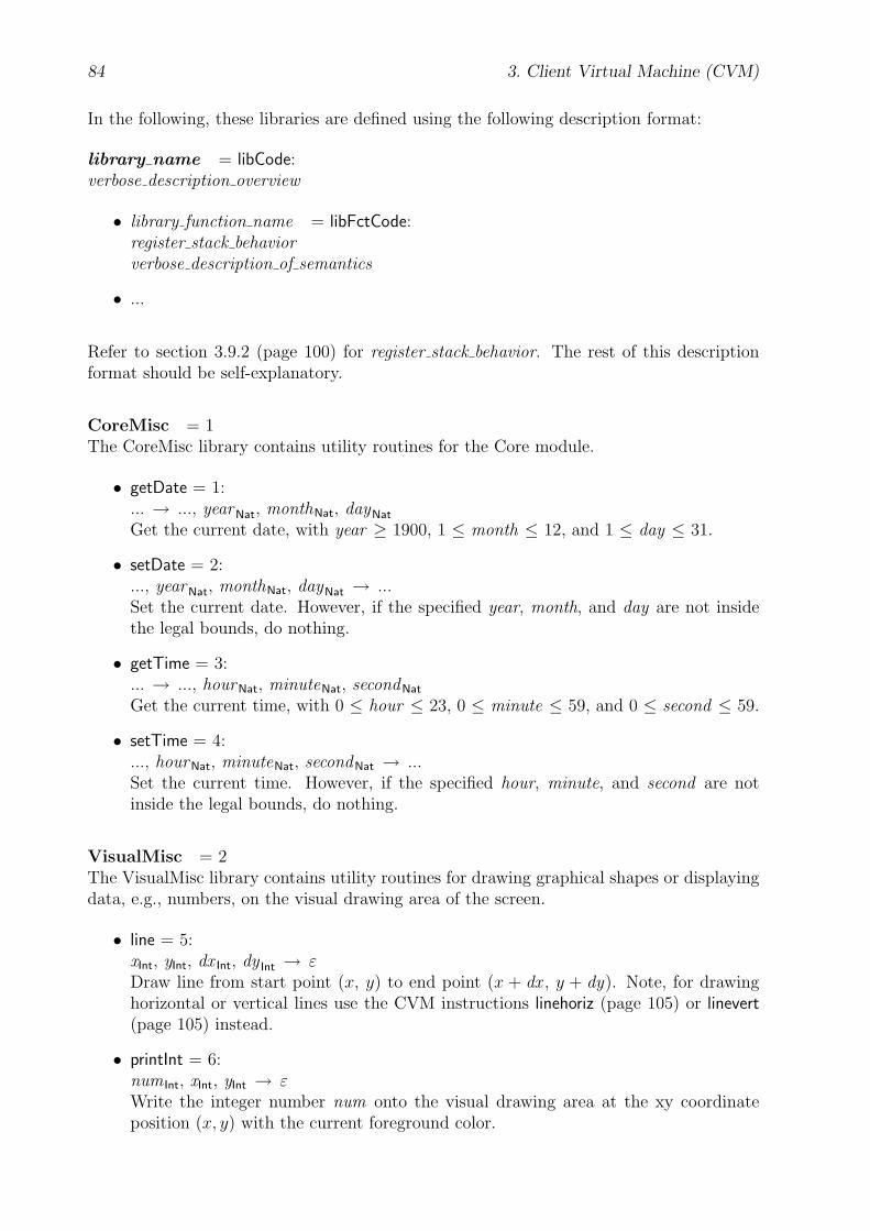
84 3. Client Virtual Machine (CVM)
In the following, these libraries are defined using the following description format:
library name = libCode:verbose description overview
• library function name = libFctCode:register stack behaviorverbose description of semantics
• ...
Refer to section 3.9.2 (page 100) for register stack behavior. The rest of this descriptionformat should be self-explanatory.
CoreMisc = 1The CoreMisc library contains utility routines for the Core module.
• getDate = 1:... → ..., yearNat, monthNat, dayNat
Get the current date, with year ≥ 1900, 1 ≤ month ≤ 12, and 1 ≤ day ≤ 31.
• setDate = 2:..., yearNat, monthNat, dayNat → ...Set the current date. However, if the specified year, month, and day are not insidethe legal bounds, do nothing.
• getTime = 3:... → ..., hourNat, minuteNat, secondNat
Get the current time, with 0 ≤ hour ≤ 23, 0 ≤ minute ≤ 59, and 0 ≤ second ≤ 59.
• setTime = 4:..., hourNat, minuteNat, secondNat → ...Set the current time. However, if the specified hour, minute, and second are notinside the legal bounds, do nothing.
VisualMisc = 2The VisualMisc library contains utility routines for drawing graphical shapes or displayingdata, e.g., numbers, on the visual drawing area of the screen.
• line = 5:xInt, yInt, dx Int, dy Int → εDraw line from start point (x, y) to end point (x + dx , y + dy). Note, for drawinghorizontal or vertical lines use the CVM instructions linehoriz (page 105) or linevert(page 105) instead.
• printInt = 6:num Int, xInt, yInt → εWrite the integer number num onto the visual drawing area at the xy coordinateposition (x, y) with the current foreground color.
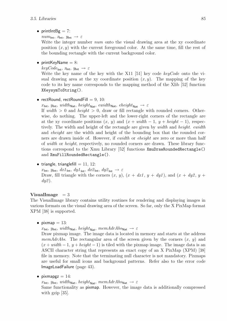
3.5. Libraries 85
• printIntBg = 7:num Int, xInt, yInt → εWrite the integer number num onto the visual drawing area at the xy coordinateposition (x, y) with the current foreground color. At the same time, fill the rest ofthe bounding rectangle with the current background color.
• printKeyName = 8:keyCode Int, xInt, yInt → εWrite the key name of the key with the X11 [51] key code keyCode onto the vi-sual drawing area at the xy coordinate position (x, y). The mapping of the keycode to its key name corresponds to the mapping method of the Xlib [52] functionXKeysymToString().
• rectRound, rectRoundFill = 9, 10:xInt, yInt, widthNat, heightNat, ewidthNat, eheightNat → εIf width > 0 and height > 0, draw or fill rectangle with rounded corners. Other-wise, do nothing. The upper-left and the lower-right corners of the rectangle areat the xy coordinate positions (x, y) and (x + width − 1, y + height − 1), respec-tively. The width and height of the rectangle are given by width and height. ewidthand eheight are the width and height of the bounding box that the rounded cor-ners are drawn inside of. However, if ewidth or eheight are zero or more than halfof width or height, respectively, no rounded corners are drawn. These library func-tions correspond to the Xmu Library [52] functions XmuDrawRoundedRectangle()
and XmuFillRoundedRectangle().
• triangle, trianglefill = 11, 12:xInt, yInt, dx1 Int, dy1 Int, dx2 Int, dy2 Int → εDraw, fill triangle with the corners (x, y), (x + dx1 , y + dy1 ), and (x + dy2 , y +dy2 ).
VisualImage = 3The VisualImage library contains utility routines for rendering and displaying images invarious formats on the visual drawing area of the screen. So far, only the X PixMap formatXPM [38] is supported.
• pixmap = 13:xInt, yInt, widthNat, heightNat, memAdrAbsNat → εDraw pixmap image. The image data is located in memory and starts at the addressmemAdrAbs. The rectangular area of the screen given by the corners (x, y) and(x+ width − 1, y+ height − 1) is tiled with the pixmap image. The image data is anASCII character string that represents an exact copy of an X PixMap (XPM) [38]file in memory. Note that the terminating null character is not mandatory. Pixmapsare useful for small icons and background patterns. Refer also to the error codeImageLoadFailure (page 43).
• pixmapgz = 14:xInt, yInt, widthNat, heightNat, memAdrAbsNat → εSame functionality as pixmap. However, the image data is additionally compressedwith gzip [35].
86 3. Client Virtual Machine (CVM)
• png = 15:xInt, yInt, widthNat, heightNat, memAdrAbsNat → εDraw PNG image. The image data is located in memory and starts at the addressmemAdrAbs. The rectangular area of the screen given by the corners (x, y) and(x+ width − 1, y+ height − 1) is tiled with the image. The format of the image datacomplies to the Portable Network Graphics (PNG) [1] image format. Refer also tothe error code ImageLoadFailure (page 43).
3.6 Home Menu
The home menu (HomeMenu) is the default menu system of the CVM. The CVM startsexecution with the home menu as soon as it is switched on. Therefore, the home menu isan essential part of the CVM and is not requested over the network from a CVM packetserver. Its format complies with the CVM packet format. Refer to section 3.8 (page 93)for more information on the CVM packet format.
Note that the contents and complexity of the home menu is implementation dependentand can be chosen freely by the vendor. For example, home menus might be providedthat are similar to the menu systems of the mobile and embedded devices in the commonmarket nowadays. To gain more flexibility, the home menu need not be fixed but canbe realized through an interchangeable card or it might be obtained from the vendor bysoftware download, which is quite useful for installing updates.
In the following, a very simple home menu is presented as a CVM assembler program.Refer to section B (page 216) for a description of the CVM assembler. Figures 3.6 (page86) and 3.7 (page 87) contain exemplary screen shots.
Figure 3.6: CVM Screen Shot 1: homeMenu.cvm
.16Bit// or .16BitEmu, .32Bit, .32BitEmu
.codeloadcr page_mainjmp
///////
// Misc///////
.const_cvmScreenWidth 250_cvmScreenHeight 150
///////
3.6. Home Menu 87
Figure 3.7: CVM Screen Shot 2: homeMenu.cvm
// Page///////
.constpage_x 5
.dataInt page_y 0
.constpage_dy 6page_w MAX (caption_w, par_w)page_h caption_h + par_h
// Foreground Colorpage_fgr 0 // Redpage_fgg 0 // Greenpage_fgb 0 // Blue
// Background Colorpage_bgr 255 // Redpage_bgg 255 // Greenpage_bgb 255 // Blue
// Fontpage_fc fcFixedStandard // Font Codepage_fs 13 // Font Sizepage_fh fontHeight (page_fc, page_fs)
.codepage_main:loadc page_fc loadc page_fs setfontloadc page_x setxtextlinefcall page_drawloadc page_et seteventtableadrenableevents
halt
.code
.fct page_draw (){Int yCaptionInt yParloadc page_bgr loadc page_bggloadc page_bgb setcolor
loadc 0 loadc 0loadc _cvmScreenWidthloadc _cvmScreenHeightrectfill
loadc page_fgr loadc page_fggloadc page_fgb setcolor
load page_y loadc caption_fh addstore yCaption
loadc caption_x load yCaptiontext caption_str
loadc caption_x load yCaption incloadc caption_w linehoriz
load yCaption loadc caption_h addstore yPar
load yPar textp par_strreturn}
.fct page_mv (Int dy){load dy loadc 0 loadcr page_mv_dnjl
page_mv_up:loadc 0 load page_y loadcr page_mv_je
loadcr page_mv_1 jmppage_mv_dn:load page_y
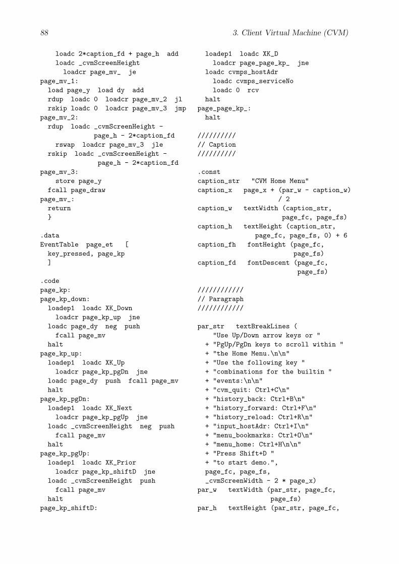
88 3. Client Virtual Machine (CVM)
loadc 2*caption_fd + page_h addloadc _cvmScreenHeightloadcr page_mv_ je
page_mv_1:load page_y load dy addrdup loadc 0 loadcr page_mv_2 jlrskip loadc 0 loadcr page_mv_3 jmp
page_mv_2:rdup loadc _cvmScreenHeight -
page_h - 2*caption_fdrswap loadcr page_mv_3 jle
rskip loadc _cvmScreenHeight -page_h - 2*caption_fd
page_mv_3:store page_y
fcall page_drawpage_mv_:
return}
.dataEventTable page_et [
key_pressed, page_kp]
.codepage_kp:page_kp_down:
loadep1 loadc XK_Downloadcr page_kp_up jne
loadc page_dy neg pushfcall page_mv
haltpage_kp_up:
loadep1 loadc XK_Uploadcr page_kp_pgDn jne
loadc page_dy push fcall page_mvhalt
page_kp_pgDn:loadep1 loadc XK_Nextloadcr page_kp_pgUp jne
loadc _cvmScreenHeight neg pushfcall page_mv
haltpage_kp_pgUp:
loadep1 loadc XK_Priorloadcr page_kp_shiftD jne
loadc _cvmScreenHeight pushfcall page_mv
haltpage_kp_shiftD:
loadep1 loadc XK_Dloadcr page_page_kp_ jne
loadc cvmps_hostAdrloadc cvmps_serviceNoloadc 0 rcv
haltpage_page_kp_:halt
//////////// Caption//////////
.constcaption_str "CVM Home Menu"caption_x page_x + (par_w - caption_w)
/ 2caption_w textWidth (caption_str,
page_fc, page_fs)caption_h textHeight (caption_str,
page_fc, page_fs, 0) + 6caption_fh fontHeight (page_fc,
page_fs)caption_fd fontDescent (page_fc,
page_fs)
////////////// Paragraph////////////
par_str textBreakLines ("Use Up/Down arrow keys or "
+ "PgUp/PgDn keys to scroll within "+ "the Home Menu.\n\n"+ "Use the following key "+ "combinations for the builtin "+ "events:\n\n"+ "cvm_quit: Ctrl+C\n"+ "history_back: Ctrl+B\n"+ "history_forward: Ctrl+F\n"+ "history_reload: Ctrl+R\n"+ "input_hostAdr: Ctrl+I\n"+ "menu_bookmarks: Ctrl+O\n"+ "menu_home: Ctrl+H\n\n"+ "Press Shift+D "+ "to start demo.",page_fc, page_fs,_cvmScreenWidth - 2 * page_x)
par_w textWidth (par_str, page_fc,page_fs)
par_h textHeight (par_str, page_fc,
3.7. CVM Profile 89
page_fs, 0)
////////////////////// CVM Packet Server////////////////////
.dataString cvmps_hostAdr "127.0.0.1"
.constcvmps_serviceNo 1
Examples of home menus can be found in the subdirectory Implementation/Cvm/Home-
Menu/.
3.7 CVM Profile
At the beginning of a request, the CVM sends its CVM profile to the CVM packet serverto report its capabilities and user preferences. The CVM packet generator then uses theseinformations to generate the client-specific CVM packets. The format of the CVM profileis presented here as a tuple data structure by using the generally understandable notationfrom section A.3 (page 208). Successive components within a tuple or array structure arestored in the CVM profile sequentially, without padding or alignment. Multibyte valuesare stored in big-endian order. Refer to section 3.1.1 (page 32) for more information onthe CVM data types Nat<1|...|4>. The array type Nat1[ ] is used for byte streams of anydata. The format of the CVM profile is as follows:
CVMProfile = { Nat1 cvmMode;Nat4 profileId;ProfileItem[ ] profileItems ;Nat1 0 }
ProfileItem = { Nat1 profileItemCode;Nat1[ ] profileItemValue }
cvmMode This item reports to the server the mode of the CVM implementation on theclient device. Refer to section 3.1.2 (page 33) for more information on CVM modes. Thereare the following values for cvmMode: 16Bit = 0, 16BitEmu = 1, 32Bit = 2, and 32BitEmu= 3. On a 16-bit CVM, cvmMode must be 16Bit or 16BitEmu. On a 32-bit CVM, cvmModemust be 32Bit or 32BitEmu.
The emulation modes 16BitEmu and 32BitEmu indicate that the CVM is implementedefficiently in software, i.e., some properties in the data and code block of the CVM programare evaluated only once at the beginning of execution and then reused all the time duringexecution. Therefore, the received CVM packet must meet some restrictions to be executedcorrectly. These restrictions are listed in section 3.8 (page 98).
profileId The profiles of the common client devices on the market might be stored bythe CVM packet server or any other server. Then, each of these profiles might be referencedby a unique integer number (profileId) and a client device with a well-known profile hasto transmit only its profile identification number to the CVM packet server. In addition,subsequent profile items (profileItems) in the CVM profile are optional and only to changethe values of that profile items which differ from those in the referenced profile.

90 3. Client Virtual Machine (CVM)
However, if profileId has the value zero, no profile is referenced and all the characteristicsof the client device are listed in the subsequent list (or array) of profile items.
The definition of profiles and profileIds for common client devices on the market is leftas an open issue in this thesis.
profileItems profileItems is a possibly empty list of profile items (ProfileItem). Theorder of the profile items is not important. Each profile item consists of a profile itemcode (profileItemCode) that identifies a particular component of the CVM, and of itsvalue (profileItemValue). Each profile item code is greater than zero. In the following, thecurrently supported profile items are listed alphabetically and described using the followingdescription format:
profile item name = profileItemCode: profileItemValueverbose description
The profile item name is the verbose name of the profileItemCode. profileItemValue isshown as a data structure. Again, subsequent items within a tuple structure are storedwithout padding or alignment.
Additional profile items, for example for the Audio module, as it is not covered in thisthesis, may be defined in the future. In addition, new profile items especially for reportinguser preferences may be defined in the future as well. For example, the user of the clientdevice might wish to enable or disable explicitly the reception of images, sound files, orother multimedia content to save network bandwidth and thus speed up download time.
cvmAudioAvailable = 1: -This profile item reports to the CVM packet server, whether the CVM module Audiois implemented on the CVM. If this profile item is not specified, no Audio module isavailable. Otherwise, it is available. This profile item does not have a profileItemValue.The specification of the Audio module is not covered in this thesis but left for future work.Therefore, if new profile items for the description of the Audio module are defined later,this profile item must not be needed anymore in this specification, because the presenceof these Audio related profile items already indicates, whether there is an Audio moduleavailable or not.
cvmDNSLookup = 2: -This profile item reports to the CVM packet server, whether the CVM can perform auto-matic DNS [45] lookup. If this profile item is specified, the CVM can perform automaticDNS lookup. Otherwise, it cannot. If the CVM supports automatic DNS lookup, theinstructions rcv, send, and sendrcv can each use DNS names to address a network host— besides IP [62] addresses in standard dot notation. This profile item does not have aprofileItemValue.
cvmFonts = 3: { Nat2 maxFontCode } | { Nat2 0; Nat2[ ] fontCodes; Nat2 0 }This profile item reports to the CVM packet server the fonts that are supported by theCVM. maxFontCode represents the maximal font code that is supported by the CVM,i.e., the CVM supports all fonts with font codes less or equal than maxFontCode. If
3.7. CVM Profile 91
maxFontCode is zero, then each supported font code is listed in the following zero ter-minated byte array fontCodes. Each font code is greater than zero. If this profile item isnot specified, the maximal supported font code is fcSymbol. This profile item must not bespecified, if the CVM has no Visual module. Refer also to section 3.2.3 (page 79) for moreinformation on CVM fonts.
cvmHeapAvailable = 4: -This profile item reports to the CVM packet server, whether the CVM has a Heap section.If this profile item is not specified, no Heap section is available. Otherwise, it is available.This profile item does not have a profileItemValue. Refer to section 3.1.4.3 (page 41) formore information on the Heap section.
cvmKeyCodeSet = 5: { Nat2 keyCodeSetId }This profile item reports to the CVM packet server the key codes that are supported bythe keyboard of the CVM. Therefore, standardized key code sets with unique identificationnumbers (keyCodeSetId) especially for restricted client devices are required. However, ifkeyCodeSetId has the value zero, all the characters (or key codes) of a customary keyboardare supported by the CVM. If this profile item is not specified, no keyboard is available onthe CVM. Refer also to section 3.3 (page 81) for more information on the CVM moduleKeyboard.
cvmLibraries = 6: { Nat1 byteLen; Nat<byteLen> [ ] libCode; Nat<byteLen> 0 }This profile item reports to the CVM packet server the libraries that are supported bythe CVM. byteLen must be in the range of 1 to 4. The following zero terminated arrayof numbers with the byte length byteLen contains the libCodes of the supported libraries.Each libCode is greater than zero. If this profile item is not specified in the profile,then no libraries are supported by the CVM. Refer also to section 3.5 (page 83) for moreinformation on CVM libraries.
cvmMeasure = 7: { Nat2 regMeasure }This profile item reports to the CVM packet server the measuring unit of the visual drawingarea of the CVM. regMeasure equals the value of the special register regMeasure. Ifthis profile item is not specified, the default value zero is assumed. If a given CVMimplementation has no Visual module, then this profile item must not be specified. Referalso to section 3.2.1 (page 77) for more information on the special register regMeasure.
cvmMemMaxAdr = 8: { Nat<cvmIntLen> cvmMemMaxAdr }This profile item reports to the CVM packet server the size of the CVM memory. cvmMem-MaxAdr refers to the highest memory address of the given CVM implementation. If thisprofile item is not specified, the memory of the CVM is “unlimited”. This is the case, if theCVM runs as an emulation on a general purpose computer with sufficient system resources.Refer also to the sections 3.1.2 (page 33) and 3.1.4 (page 36) for more information on theCVM modes and the CVM memory, respectively.

92 3. Client Virtual Machine (CVM)
cvmMouseButtons = 9: { Nat1 numButtons }This profile item reports to the CVM packet server the number of mouse buttons of theCVM, i.e., the CVM module Mouse has the mouse buttons with the numbers from 1 tonumButtons, with 1 ≤ numButtons ≤ 5. If the CVM has implemented the CVM moduleMouse, this profile item must be specified. Otherwise, not. Refer to section 3.3 (page 81)for more information on the Mouse module.
cvmNumGeneralRegs = 10: { Nat1 cvmNumGeneralRegs }This profile item reports to the CVM packet server the number of general purpose registersin the register stack of the CVM. If this profile item is not specified, the default value 10 isassumed. However, the value zero indicates that an “unlimited” number of general purposeregisters are available. This is the case, if the CVM runs as an emulation on a generalpurpose computer with sufficient system resources such as a PC or workstation. Refer alsoto section 3.1.3 (page 34) for more information on the register stack.
cvmOutputCharSet = 11: { Nat1[ ] charBlockNames; Nat1 0 }This profile item reports to the CVM packet server the Unicode [88] character blocks thatare supported by the CVM’s output device(s) to display. charBlockNames consists onlyof printable ASCII characters from the US-ASCII charset and contains a comma sepa-rated list of Unicode character block names. For example, the value of charBlockNames
might be “Basic Latin,Latin-1 Supplement,Miscellaneous Symbols,Supplemental
Mathematical Operators”. However, if this profile item is not specified, then the de-fault Unicode character blocks “Basic Latin,Latin-1 Supplement” are assumed.
cvmUPLanguage = 12: { Nat2 num }This profile item reports to the CVM packet server the preferred language of the textualcontent that is presented on the CVM. num is a unique number greater than zero identifyinga particular natural language. The definition of unique numbers for all kinds of existinglanguages is left as an open issue in this thesis. Here, as a proof of concept, the numbers 1and 2 are defined for the languages English-US and German, respectively. Note that thisuser preference is just a hint but not a must for the CVM packet server. It can still sendthe textual content in another language. If this profile item is not specified, then the CVMpacket server can choose the language.
cvmScreenHeight = 13: { Nat2 num }This profile item reports to the CVM packet server the height of the client device’s visualdrawing area in pixels. If the CVM has a screen and the module Visual is implemented,this profile item must always be specified; there is no default value for it. If this profileitem is not specified, then the CVM has no Visual module.
cvmScreenHeightMM = 14: { Nat2 num }This profile item reports to the CVM packet server the height of the client device’s visualdrawing area in tenths of a millimeter. If the CVM has the module Visual implementedand if the value of the special register regMeasure is not zero, this profile item must alwaysbe specified; there is no default value for it.
3.8. CVM Packet 93
cvmScreenWidth = 15: { Nat2 num }This profile item reports to the CVM packet server the width of the client device’s visualdrawing area in pixels. If the CVM has a screen and the module Visual is implemented,this profile item must always be specified; there is no default value for it. If this profileitem is not specified, then the CVM has no Visual module.
cvmScreenWidthMM = 16: { Nat2 num }This profile item reports to the CVM packet server the width of the client device’s visualdrawing area in tenths of a millimeter. If the CVM has implemented the module Visualand if the value of the special register regMeasure is not zero, this profile item must alwaysbe specified; there is no default value for it.
cvmTimerAvailable = 17: -This profile item reports to the CVM packet server, whether the CVM has an intervaltimer. If this profile item is not specified, no interval timer is available. Otherwise, it isavailable. This profile item does not have a profileItemValue. Refer to section 3.1.9 (page57) for more information on the interval timer.
Comments The profile items can also be grouped according to the CVM module theybelong to, respectively. Profile items that refer to the user preferences are listed at theend.
• Core: cvmHeapAvailable, cvmMemMaxAdr, cvmNumGeneralRegs, cvmTimerAvailable
• Visual: cvmFonts, cvmMeasure, cvmOutputCharSet, cvmScreenWidth, cvmScreenWidth-MM, cvmScreenHeight, cvmScreenHeightMM
• Audio: cvmAudioAvailable, cvmOutputCharSet
• Keyboard: cvmKeyCodeSet
• Mouse: cvmMouseButtons
• Network: cvmDNSLookup
• Libraries: cvmLibraries
• User Preferences: cvmUPLanguage
3.8 CVM Packet
A CVM packet is transmitted from the CVM packet server to the client and represents thebinary executable for the CVM. The term CVM program, however, is used to refer to thedata and code of the CVM packet after it has been loaded into memory by the CVM. ACVM packet is a stream of 8-bit bytes. Its format is presented here as a tuple data structureby using the generally understandable notation from section A.3 (page 208). Successivecomponents within a tuple or array structure are stored in the CVM packet sequentially,without padding or alignment. Multibyte values are stored in big-endian order. Refer
94 3. Client Virtual Machine (CVM)
to section 3.1.1 (page 32) for more information on the CVM data types Int<1|...|4> andNat<1|...|4>. The array type Nat1[ ] is used for byte streams of any data. The generalCVM packet format is as follows:
CVMPacket = { Nat4 magic;Nat1 attributes;Nat<cvmpAdrLen> dataDeclSegmentAdr,
codeSegmentAdr,stackSegmentAdr,lenDataDecl,lenInstructions;
Declaration[ ] data;Instruction[ ] instructions }
Declaration = { Nat1 declCode;Nat1[ ] dataBytes }
Instruction = { Nat1 opcode;Nat1[ ] immOperands }
magic The value of the magic item identifies the format of the byte stream and must be0x63766D70, which corresponds to the ASCII sequence ’CVMP’.
attributes This packet item contains the operation mode of the CVM, for which thisCVM packet is destined to, and the byte length of the memory addresses that are hardcodedin the CVM packet. Hardcoded memory addresses are the next three following packet itemsand the memory addresses in the event table structure. Refer to the data declaration codeeventtable in section 3.8 (page 96) for more information on the event table structure in theCVM packet. The operation mode is referred to with the term cvmMode, the byte length ofthe hardcoded memory addresses is referred to with the term cvmpAdrLen. cvmMode mustbe equal to the CVM profile item cvmMode which has been sent by the CVM previously tothe CVM packet server during the client request. The values of cvmMode and cvmpAdrLen
are extracted from attributes as follows:
cvmMode = attributes & 0x03. So far, cvmMode may only have the value 0, 1, 2, or 3,which corresponds to the CVM mode 16Bit, 16BitEmu, 32Bit, or 32BitEmu, respectively.As already said in section 3.1.2 (page 33), the value of cvmIntLen is 2, if cvmMode is 16Bitor 16BitEmu, and 4, if cvmMode is 32Bit or 32BitEmu.
cvmpAdrLen = ((attributes � 4) & 0x03) + 1. If the value of cvmMode is 16Bit or16BitEmu, then cvmpAdrLen may only have the value 1 or 2. If the value of cvmMode is32Bit or 32BitEmu, then cvmpAdrLen may only have the value 1, 2, 3, or 4. To save packetsize and thus network bandwidth, cvmpAdrLen is set by the CVM packet generator to theminimum number of bytes that is required by the largest hardcoded memory address whichappears in this CVM packet.
dataDeclSegmentAdr This packet item contains the starting memory address of the datathat is declared in this packet. The declared data is listed in the data section of the CVM
3.8. CVM Packet 95
packet and copied into CVM memory beginning at the address dataDeclSegmentAdr.The Declared Data section extends to the beginning of the Code section which startsat the memory address codeSegmentAdr. Refer to section 3.1.4.1 (page 37) for moreinformation on the Data section. The byte length of this packet item depends on the valueof cvmpAdrLen.
Depending on the CVM mode, the first byte of the declared data in CVM memory isaligned on a 2- or 4-byte boundary. That is, on a 16-bit CVM, dataDeclSegmentAdr is amultiple of 2, and on a 32-bit CVM, dataDeclSegmentAdr is a multiple of 4.
If the CVM mode is not an emulation mode, i.e., if the CVM mode is not 16BitEmu or32BitEmu, then only data with essential initial values are declared in the CVM packet.The event table data items are declared by the declaration code eventtable. All otherdata items are grouped together and declared by using one of the appropriate declarationcodes bytesz<1|...|4> and bytes<1|...|4>, respectively, to save packet size and thus networkbandwidth.
If the CVM mode is an emulation mode, then every single data item is declared separatelywith at least the “dummy” initial value zero.
dataDeclSegmentAdr must be an unsigned integer number less than or equal to cvmMem-MaxAdr.
codeSegmentAdr This packet item contains the starting memory address of the Codesection in CVM memory. The transmitted CVM instructions inside the instructions arrayare copied into this memory section starting at the address codeSegmentAdr. The Codesection extends to the beginning of the Stack section. Refer to section 3.1.4.1 (page 37)for more information on the Code section.
After loading the CVM packet into CVM memory, the CVM starts execution with theinstruction at the memory address codeSegmentAdr. However, if the CVM packet has beenreceived from a CVM packet server within a CPTP message using the protocol methodCVMP, the CVM starts execution at the memory address that is given by the protocolmessage item pageMemAdr. Refer to sections 4 (page 127) and 4.2 (page 129) for moreinformation on the CPTP protocol and on the protocol method CVMP.
Depending on the CVM mode, the first byte of the code array in CVM memory is alignedon a 2- or 4-byte boundary. That is, on a 16-bit CVM, codeSegmentAdr is a multiple of2, and on a 32-bit CVM, codeSegmentAdr is a multiple of 4.
codeSegmentAdr must be an unsigned integer number greater than or equal to dataDecl-
SegmentAdr + lenDataDecl, but less than or equal to stackSegmentAdr.
stackSegmentAdr This packet item contains the starting memory address of the Stacksection in CVM memory. The Stack section extends to the end of the CVM memory. Referto section 3.1.4.2 (page 38) for more information on the Stack section.
Depending on the CVM mode, the first byte of the Stack section in CVM memory is alignedon a 2- or 4-byte boundary. That is, on a 16-bit CVM, stackSegmentAdr is a multiple of2, and on a 32-bit CVM, stackSegmentAdr is a multiple of 4.
stackSegmentAdr must be an unsigned integer number greater than or equal to codeSeg-
mentAdr + lenInstructions, but less than or equal to cvmMemMaxAdr.
96 3. Client Virtual Machine (CVM)
lenDataDecl This packet item contains the total byte length of all data declarationswithin the data section of the CVM packet. lenDataDecl must be an unsigned integernumber less than or equal to cvmMemMaxAdr.
lenInstructions This packet item contains the total byte length of all instructionswithin the instructions section of the CVM packet. lenInstructions must be an un-signed integer number less than or equal to cvmMemMaxAdr.
data data is a sequence (or array) of data declarations and their initial values. Eachdeclaration consists of its declaration code (declCode) and the data bytes (dataBytes) thatcontain the initial value. During loading a CVM packet, the CVM copies the initial valuesinto the Declared Data section in memory starting at the address dataDeclSegmentAdr
in the same order as they appear in the CVM packet. Note that depending on the CVMmode, all initial values are aligned on a 2- or 4-byte boundary. That is, the CVM placesthe first byte of each initial value in memory at an address that is a multiple of 2 on a16-bit CVM, or a multiple of 4 on a 32-bit CVM. In the following, the currently supporteddeclaration codes are listed alphabetically and described using the following descriptionformat:
declaration code name = declCode: dataBytes
verbose description
The declaration code name is the verbose name of the declCode. dataBytes is specifiedas a tuple structure. Dependent on the declaration code, however, it may also be empty.
bytes<i> (1 ≤ i ≤ 4) = 1 + i− 1: { Nat<i> numBytes; Nat1[numBytes] val }Declaration of a sequence of bytes with numBytes representing its byte length and val
representing the initial byte values. Note that only the first byte of the byte array val
is aligned on a 2- or 4- byte boundary on a 16-bit or 32-bit CVM, respectively. Forperformance reasons, integer numbers that occur inside this byte array should be alignedproperly in the CVM packet by padding zero bytes. Note that the declaration codes bytes3and bytes4 are only supported by a 32-bit CVM.
bytesz<i> (1 ≤ i ≤ 4) = 5 + i− 1: { Nat<i> numBytes }Declaration of a sequence of zero bytes with numBytes representing its byte length. Theinitial zero bytes are not transmitted over the network to save bandwidth. The CVMautomatically fills the memory cells mem[j], ..., mem[j + numBytes − 1] with zero bytes,with j representing the next following absolute memory address that is a multiple of 2 or4 on a 16-bit or 32-bit CVM, respectively. For performance reasons, integer numbers thatoccur inside this byte array should be aligned properly in the CVM packet by padding zerobytes. Note that the declaration codes bytesz3 and bytesz4 are only supported by a 32-bitCVM.
eventtable = 9: EventTableThe binary packet format of EventTable is as follows:

3.8. CVM Packet 97
EventTable = { EventTableEntry [ ] entries ;Nat1 0 }
EventTableEntry = { Nat1 eventCode, // eventCode > 0
Nat<cvmpAdrLen> memAdr }
An event table is a (possibly empty) list of event table entries, whereas each entry consistsof an event code (eventCode) and the absolute memory address (memAdr) of an instruction.cvmpAdrLen is a part of the CVM packet item attributes and specifies the byte lengthof each memory address. The end of the list is indicated by the value 0 for the event code.Refer also to section 3.1.6.2 (48) for the binary format of the event table in CVM memory,after it has been loaded by the CVM.
On a 16- or 32-bit CVM, each memAdr must be an unsigned integer number less than 216
or 231, respectively.
int<i> (1 ≤ i ≤ 4) = 10 + i− 1: { Int<i> val }Declaration of an i -byte signed integer number (Int<i>) with the initial value val. On a16-bit CVM, only the declaration codes int1 and int2 are supported and val is copied asan Int2 value into memory. On a 32-bit CVM, val is copied as an Int4 value into memory.These declaration codes are only supported, if the CVM is emulated in software, i.e., if theCVM mode is 16BitEmu or 32BitEmu. Otherwise, all data items with initial values unequalto zero must be combined by using the bytes<i> (1 ≤ i ≤ 4) declaration code.
intz = 14: -Declaration of a signed integer number (Int<cvmIntLen>) with the initial value zero. TheCVM automatically fills the memory cells mem[j], ..., mem[j + cvmIntLen − 1] with zerobytes, with j representing the next following absolute memory address which is a multipleof 2 or 4 on a 16-bit or 32-bit CVM, respectively. This declaration code is only supported,if the CVM is emulated in software, i.e., if the CVM mode is 16BitEmu or 32BitEmu.Otherwise, all data items with initial values equal to zero must be grouped together byusing the bytesz declaration code.
nat<i> (1 ≤ i ≤ 3) = 15 + i− 1: { Nat<i> val }Declaration of an i -byte unsigned integer number (Nat<i>) with the initial value val.On a 16-bit CVM, only the declaration code nat1 is supported and val is then copiedas an Int2 value into memory. On a 32-bit CVM, val is copied as an Int4 value intomemory. An arithmetic overflow is not checked by the CVM. These declaration codes areonly supported, if the CVM is emulated in software, i.e., if the CVM mode is 16BitEmu or32BitEmu. Otherwise, all data items with initial values unequal to zero must be combinedby using the bytes<i> (1 ≤ i ≤ 4) declaration code.
string = 18: (String val)Declaration of the string val. This declaration code is only supported, if the CVM isemulated in software, i.e., if the CVM mode is 16BitEmu or 32BitEmu. In addition, thestring val must not be modified, but must be treated as a constant during execution ofthe CVM program.
98 3. Client Virtual Machine (CVM)
instructions instructions is a sequence of CVM instructions. Each instruction consistsof its operation code (opcode) and possibly some immediate operands (immOperands).The opcode and — if existent — the immediate operands of each instruction are copiedinto memory starting at the memory address codeSegmentAdr without alignment, exceptfor the opcode of the first instruction. Forgoing alignment makes CVM code in memorymore compact; however, possibly at the cost of a performance penalty in particular CVMimplementations. Refer to section 3.9.2 (page 100) for a complete reference of all CVMinstructions.
CVM Packet Verifier During loading of a CVM packet into memory the CVM packetverifier checks the constraints that are mentioned in the description of the CVM packetformat. This prevents the CVM from executing malformed CVM packets. As a result, asimple kind of low-level security is achieved.
Restrictions for an Emulated CVM If the CVM is emulated, i.e., cvmMode is 16Bit-Emu or 32BitEmu, the data and code part of the CVM packet has to meet the followingconditions:
• During runtime, the instructions are not overwritten and no new instruction is createdto be executed.
• All jump target addresses of the control flow instructions call, jmp, ..., are knownbefore runtime and do not change during runtime.
• Every data item is declared in the CVM packet and properly accessed by the CVMinstructions according to the type of its declaration. Refer to section 3.8 (page 96)for more information on data declarations within the CVM packet.
• Declared strings (string) remain constant in memory, i.e., they are not modified duringruntime.
As a result, the CVM can be implemented more efficiently in software, because certainproperties, e.g., the memory addresses of the data items and the jump targets, can beevaluated once at the beginning of program execution and then reused all the time duringexecution. In addition, similar to the Java HotSpot Virtual Machine [76], Just-In-Timecompilation techniques may be applied as well. Note that the implementation of suchoptimizations is not mandatory and left to the implementors’ choice. Therefore, theseoptimizations are not going to be discussed here in more detail.
3.9 Instruction Set
In order to keep the CVM architecture as simple as possible, the CVM instruction setcontains only the most essential operations that are needed for networked clients. Inaddition to instructions for common processing, it covers mainly instructions for displayinguser interfaces. So far, there are 111 instructions altogether for the CVM modules Core,Visual, Keyboard, Mouse, Network, and Libraries.
3.9. Instruction Set 99
However, a given CVM implementation does not need to support any instructions thatbelong to a nonexistent module or functional unit. The modules Visual, Audio, Keyboard,Mouse, and Libraries as well as the functional units for the management of the optionalHeap section and the optional interval timer within the Core module are optional.
Note that the instructions aload4, astore4, loadc3, loadc4, loadcu2, loadcu3, setcolor32, set-bgcolor32, and setfont32 are only supported by a 32-bit CVM, but not by a 16-bit CVM.Therefore, a very “thin” 16-bit CVM implementation with a screen and keyboard, but with-out a Heap section, an interval timer, a mouse, and without any libraries has to supportonly 94 instructions.
3.9.1 Overview
This section summarizes all CVM instructions and groups them according to the CVMmodules they belong to, and within a CVM module according to their purposes. Mostinstructions are motivated and introduced in the respective CVM module descriptions inthe previous sections. A comprehensive description of each instruction is given in thefollowing reference section.
Core
• Load immediate integer value onto register stack: loadc<1|...|4>, loadcu<1|...|3>,loadc 0, loadc 1, loadc m1
• Load integer value from memory onto register stack: loada, loadr
• Write integer value from register stack into memory: storea, storer
• Load integer value from array in memory onto register stack: aload<1|2|4>
• Write integer value from register stack into array in memory: astore<1|2|4>
• Load integer value from memory stack onto register stack and vice versa: pop, push
• Heap management: new, free, hload, hstoreNote that the Heap section is optional for a given CVM implementation.
• Bit test and set operations: testsetbits, unsetbits
• Register stack management: rdup, rempty, rskip, rswap
• Base Pointer (regBP): newstackframe, oldstackframe, getbp, setbp
• Stack Pointer (regSP): addsp, decsp, incsp
• Binary arithmetic operations: add, sub, mul, div, rem, and, or, xor, shl, shr, shrs
• Unary arithmetic operations: dec, inc, neg, not
• Control flow: halt, call, ret, jmp, je, jne, jl, jle, page
• Event handling: enableevents, disableevents, loadep<1|2|3>, seteventtableadr
• Interval timer: settimerinterval, settimerhandleadrNote that the interval timer is optional for a given CVM implementation.

100 3. Client Virtual Machine (CVM)
Visual
• Graphics state: setbgcolor, setbgcolor32, setbgred, setbggreen, setbgblue, setcolor,setcolor32, setred, setgreen, setblue, setfont, setfont32, setfontcode, setfontsize, seth-textline, setxtextline, setclip, setlinewidth
• Lines: linehoriz, linevert
• Rectangles: rect, rectfill
• Circles: circle, circlefill
• Text: text, textm, textp, textpm, textbg, textmbg, textpbg, textpmbg
• Bitmaps: bitmap, bitmapbg
• Screen buffering: mem2screen, screen2mem,
Audio (Not covered in this thesis)
Keyboard (So far, no instructions)
Mouse, Network, Libraries
• Set mouse shape: setmousefont
• Receive and send data over network: rcv, sendrcv
• Set regSessionId to zero: sid
• Call library function: libNote that the lib instruction is always implemented, even if no libraries are available.Then, a library call always results in the error UnknownLibraryFunction.
3.9.2 Reference
This section serves as a reference and describes all instructions. They are listed alphabet-ically using the following description format:
mnemonic = opcode: immediate operandsregister stack behaviorverbose description of semantics
opcode is the positive integer number that identifies the instruction in the binary code.
immediate operands represents a (possibly empty) list of immediate operands. Immediateoperands of an instruction appear in the binary code right after the instruction opcode.Each immediate operand is shown in the form identtype . ident can be any identifier and isusually chosen to characterize the use of the operand. type denotes the type of the operandand may be one of the CVM data types Int, Nat, or String. For example, xNat might be

3.9. Instruction Set 101
used to identify an x coordinate value of the type Nat. If the instruction does not have anyimmediate operands, immediate operands is omitted in the description of that instruction.Only a few instructions have immediate operands.
register stack behavior illustrates how the instruction affects the register stack. It is shownin the form preRegStack → postRegStack. preRegStack represents the register stack rightbefore the execution of the instruction. It has the form “..., value1 , value2 , ..., valuen” withvaluei = R[regRSP − n + i] (0 < i ≤ n ≤ cvmNumGeneralRegs). postRegStack representsthe register stack right after the execution of the instruction. It has the form “..., result1 ,result2 , ..., resultm” with resultj = R[regRSP−m+ j] (0 < j ≤ m ≤ cvmNumGeneralRegs).An instruction pops the values value1 , ..., valuen (0 ≤ n ≤ cvmNumGeneralRegs) asoperands from the register stack and pushes the results result1 , ..., resultm (0 ≤ m ≤cvmNumGeneralRegs) onto it. The values of the numbers n and m depend on the partic-ular instruction. valuei (0 < i ≤ n) and resultj (0 < j ≤ m) are shown in the formidenttype as well. Accordingly, if no underflow or overflow occurs, the Register StackPointer regRSP is adjusted automatically during the execution of the instruction, i.e.,regRSPpostRegStack = regRSPpreRegStack − n + m. Refer also to the error codes RegisterStack-Overflow, RegisterStackStaticOverflow, and RegisterStackUnderflow.
The remainder of the register stack, i.e., the initial “...” in preRegStack and postRegStack,remains unaffected by the instruction. Note that if the instruction is a final one, theremainder is supposed to be empty and therefore omitted in the instruction description.Then it holds: valuei = R[i] (0 < i ≤ n ≤ cvmNumGeneralRegs) in preRegStack andresultj = R[j] (0 < j ≤ m ≤ cvmNumGeneralRegs) in postRegStack. An empty registerstack is indicated by the symbol ε. If the instruction does not affect the register stack atall, register stack behavior is omitted in the instruction description.
verbose description of semantics provides a verbose description of the instruction seman-tics.
The byte lengths of Int and Nat are given by cvmIntLen. Note that if cvmIntLen is 4, thebiggest Nat number is 231 − 1, but not 232 − 1.
Note that all CVM instructions are atomic, i.e., no instruction may be interrupted duringits execution. Interrupt handling may only take place between two subsequent instructions.
add = 1:..., num1 Int, num2 Int → ..., result Int
Add the numbers num1 and num2. On a 16-bit CVM, result = (num1 + num2 ) & 0xFFFF.On a 32-bit CVM, result = (num1 + num2 ) & 0xFFFFFFFF.
addsp = 2:..., numStackCells Int → ...Increment/Decrement stack pointer register regSP. On a 16-bit CVM, regSP := (regSP+ ((numStackCells ∗ 2) & 0xFFFF)) & 0xFFFF. On a 32-bit CVM, regSP := (regSP +((numStackCells ∗ 4) & 0xFFFFFFFF)) & 0xFFFFFFFF. If the new value of regSP is lessthan regSS or greater than cvmMemMaxAdr + 1, start error handling with the error codeStackUnderflow (page 44) or StackOverflow (page 44), respectively.

102 3. Client Virtual Machine (CVM)
aload1 = 3:..., arrayAdrNat, index Int → ..., arrayElemNat
Load Nat1 number from byte array in memory onto register stack with zero extension.The number is an array element. On a 16-bit CVM, it starts in memory at the address(arrayAdr + index ) & 0xFFFF. On a 32-bit CVM, its memory address is (arrayAdr +index ) & 0xFFFFFFFF. Refer also to the error code IllegalMemoryAddress (page 43).
aload<2|4> = 4, 5:..., arrayAdrNat, index Int → ..., arrayElem Int
Load Int<2|4> number from integer array in memory onto register stack with sign exten-sion, respectively. The (big-endian) number is an array element. On a 16-bit CVM, itstarts in memory at the address (arrayAdr + ((index ∗ 2) & 0xFFFF)) & 0xFFFF. On a 32-bit CVM, its memory address is (arrayAdr + ((index ∗ i) & 0xFFFFFFFF)) & 0xFFFFFFFF,with i = 2 or 4, respectively. aload4 is only supported by a 32-bit CVM. Refer also to theerror code IllegalMemoryAddress (page 43).
and = 6:..., num1 Int, num2 Int → ..., result Int
Bitwise AND conjunction with result = num1 & num2.
astore1 = 7:..., value Int, arrayAdrNat, index Int → ...Store the least significant byte of value, i.e., value & 0xFF, into the byte array in memoryat the address targetAdr. On a 16-bit CVM, targetAdr = (arrayAdr + index ) & 0xFFFF.On a 32-bit CVM, targetAdr = (arrayAdr + index ) & 0xFFFFFFFF. Refer also to the errorcode IllegalMemoryAddress (page 43).
astore<2|4> = 8, 9:..., value Int, arrayAdrNat, index Int → ...Store the least 2 or 4 significant bytes of value, i.e., value & 0xFFFF or value & 0xFFFFFFFF,into the integer array in memory at the address targetAdr in big-endian order. On a 16-bitCVM, targetAdr = (arrayAdr + ((index ∗ 2) & 0xFFFF)) & 0xFFFF. On a 32-bit CVM,targetAdr = (arrayAdr + ((index ∗ i) & 0xFFFFFFFF)) & 0xFFFFFFFF, with i = 2 or 4,respectively. astore4 is only supported by a 32-bit CVM. Refer also to the error codeIllegalMemoryAddress (page 43).
bitmap, bitmapbg = 10, 11:xInt, yInt, widthNat, heightNat, memAdrAbsNat → εDraw bitmap image. The image data is located in memory and starts at the addressmemAdrAbs. The rectangular area of the screen given by the corners (x, y) and (x +width − 1, y + height − 1) is tiled with the bitmap image. The pixels that are set in thebitmap image are drawn with the foreground color. The only difference between bitmapand bitmapbg is that bitmap leaves the unset pixels untouched, whereas bitmapbg addition-ally draws the unset pixels with the background color. The binary format of the imagedata in memory, shown as a tuple structure, is as follows:(Nat bitmapWidth, Nat bitmapHeight, Nat1[bitmapWidth∗bitmapHeight] dataBytes)

3.9. Instruction Set 103
On a 16-bit CVM, the byte length of Nat is 2. On a 32-bit CVM, it is 4. bitmapHeight
and bitmapWidth specify the width and height of the bitmap, respectively. The binaryformat of dataBytes complies to the X BitMap format XBM [96]. Refer to the section3.2.1 (page 76) for more information on foreground and background colors. Refer also tothe error code ImageLoadFailure (page 43).
call = 12:..., memAdrRel Int → ...Procedure call. Push the memory address of the immediately following instruction onto thememory stack, i.e., store that memory address onto the top of the memory stack and in-crement regSP by cvmIntLen. Then jump to the instruction at the relative memory addressmemAdrRel and continue execution there, i.e., regIP := regIP + memAdrRel . Note thatthe value of regIP on the right side equals the absolute memory address of the instructionopcode. After execution of the procedure is finished, i.e., the instruction ret within thatprocedure is encountered, resume execution with the immediately following instructionfrom before. Refer also to the error codes StackOverflow (page 44) and IllegalMemoryAd-dress (page 43), to the instruction ret (page 109), to the procedure stack frame (page 40),and to section 3.1.2 (page 33) for more information on cvmIntLen.
circle, circlefill = 13, 14:xInt, yInt, widthNat → εIf width > 0, draw or fill circle that is delimited by the bounding square, respectively.Otherwise, do nothing. The coordinates of the upper left corner and the width of thebounding square are given by x, y, and width.
dec = 15:..., num Int → ..., result Int
Decrement num. On a 16-bit CVM, result = (num − 1) & 0xFFFF. On a 32-bit CVM,result = (num − 1) & 0xFFFFFFFF.
decsp = 16:Decrement stack pointer register regSP. On a 16-bit CVM, regSP := (regSP − cvmIntLen) &0xFFFF. On a 32-bit CVM, regSP := (regSP − cvmIntLen) & 0xFFFFFFFF. If the new valueof regSP is less than regSS or greater than cvmMaxMemAdr + 1, start error handling withthe error code StackUnderflow (page 44) or StackOverflow (page 44), respectively. Refer tosection 3.1.2 (page 33) for more information on cvmIntLen.
disableevents = 17:Disable event handling, i.e., regEventEnable := 0. From now on, all events except for thebuiltin events will be discarded until the instruction enableevents occurs.
div = 18:..., num1 Int, num2 Int → ..., result Int
Integer division. If num2 6= 0, result = num1 / num2. Otherwise, start error handlingwith error code DivisionByZero (page 43).
104 3. Client Virtual Machine (CVM)
enableevents = 19:Enable event handling, i.e., regEventEnable := 1. From now on, all events will be processeduntil the instruction disableevents occurs.
free = 20:..., heapAdrNat → ...Free the memory region in the Heap section that starts at the heap address heapAdr . Notethat this memory region must have been reserved before with the library function new.The byte length of the memory region is known, because it is an operand of new. If thespecified memory region has not been reserved before or if it has already been freed before,undefined behavior occurs. Refer to section 3.1.4.3 (page 41) for more information on theHeap section.
getbp = 21:... → ..., memAdrAbsNat
Load the value of the base pointer register onto the register stack, i.e., memAdrAbs :=regBP.
halt = 0:... → εStop execution and wait.
hload = 22:..., heapAdrNat → ..., value Int
Load integer number from the Heap section onto the register stack. The number resides inthe Heap section at the address heapAdr . The byte length of the integer number dependson the CVM mode and is given by cvmIntLen. If the heap address heapAdr is not valid, theCVM aborts execution and starts error handling with the error code IllegalMemoryAddress.Refer to the sections 3.1.2 (page 33) and 3.1.4.3 (page 41) for more information on CVMmodes and cvmIntLen and on the Heap section, respectively.
hstore = 23:..., value Int, heapAdrNat → ...Store integer number value from register stack into the Heap section at the addressheapAdr . The byte length of the integer number depends on the CVM mode and is givenby cvmIntLen. If the heap address heapAdr is not valid, the CVM aborts execution andstarts error handling with the error code IllegalMemoryAddress. Refer to the sections 3.1.2(page 33) and 3.1.4.3 (page 41) for more information on CVM modes and cvmIntLen andon the Heap section, respectively.
inc = 24:..., num Int → ..., result Int
Increment num. On a 16-bit CVM, result = (num + 1) & 0xFFFF. On a 32-bit CVM,result = (num + 1) & 0xFFFFFFFF.

3.9. Instruction Set 105
incsp = 25:Increment stack pointer register regSP. On a 16-bit CVM, regSP := (regSP + cvmIntLen) &0xFFFF. On a 32-bit CVM, regSP := (regSP + cvmIntLen) & 0xFFFFFFFF. If the new valueof regSP is less than regSS or greater than cvmMaxMemAdr + 1, start error handling withthe error code StackUnderflow (page 44) or StackOverflow (page 44), respectively. Refer tosection 3.1.2 (page 33) for more information on cvmIntLen.
jmp = 26:..., memAdrRel Int → ...Unconditional jump to the instruction at the relative memory address memAdrRel. Proceedexecution there, i.e., regIP := regIP + memAdrRel. Note that the value of regIP on theright side equals the absolute memory address of the instruction opcode. Refer also to theerror code IllegalMemoryAddress (page 43).
j<e |ne | l | le> = 27, 28, 29, 30:..., num1 Int, num2 Int, memAdrRel Int → ...Conditional jump. If the condition is true, jump to the instruction at the relative memoryaddress memAdrRel and proceed execution there, i.e., regIP := regIP + memAdrRel. Notethat the value of regIP on the right side equals the absolute memory address of the in-struction opcode. The conditions are defined by: “e” ≡ “num1 = num2 ”, “ne” ≡ “num16= num2 ”, “l” ≡ “num1 < num2 ”, “le” ≡ “num1 ≤ num2 ”. Refer also to the error codeIllegalMemoryAddress (page 43).
lib = 31:..., par1 Int, ..., parN Int, fctCodeNat → ...Call library function with the libFctCode fctCode. par1, ..., parN (N ≥ 0) are the parame-ters of the library function. Refer to section 3.5 (page 83) for a list of all currently availablelibrary functions. Refer also to the error code UnknownLibraryFunction (page 45).
linehoriz = 32:xInt, yInt, lenNat → εIf len > 0, draw horizontal line from start point (x, y) to end point (x + len − 1, y).Otherwise, do nothing.
linevert = 33:xInt, yInt, lenNat → εIf len > 0, draw vertical line from start point (x, y) to end point (x, y+ len−1). Otherwise,do nothing.
loada = 34:..., memAdrAbsNat → ..., num Int
Load integer number from memory onto register stack. The number resides in memoryat the address memAdrAbs in big-endian order. The byte length of the integer numberdepends on the CVM mode and is given by cvmIntLen. Refer to section 3.1.2 (page 33) formore information on CVM modes and cvmIntLen. Refer also to the error code IllegalMem-oryAddress (page 43).
106 3. Client Virtual Machine (CVM)
loadc 0, loadc 1, loadc m1 = 35, 36, 37:... → ..., num Int
Load the integer constants 0, 1, −1 onto the register stack, respectively.
loadc<i> (1 ≤ i ≤ 4) = 38, 39, 40, 41: num Int<i>
... → ..., num Int
Load the i-byte signed integer constant num in big-endian order onto the register stack(with sign extension). loadc3 and loadc4 are only supported by a 32-bit CVM.
loadcu<i> (1 ≤ i ≤ 3) = 42, 43, 44: numNat<i>
... → ..., numNat
Load the i -byte unsigned integer constant num in big-endian order onto the register stack(without sign extension). loadcu2 and loadcu3 are only supported by a 32-bit CVM.
loadep<i> (1 ≤ i ≤ 3) = 45, 46, 47:... → ..., val Int
Load the value of the special event parameter register regEventPar<i> onto the registerstack, with val = regEventPar<i>.
loadr = 48:..., memAdrRel Int → ..., num Int
Load integer number from memory onto register stack. The number resides in memory atthe address memAdrAbs in big-endian order. On a 16-bit CVM, memAdrAbs = (regBP+ memAdrRel) & 0xFFFF. On a 32-bit CVM, memAdrAbs = (regBP + memAdrRel) &0xFFFFFFFF. The byte length of the integer number depends on the CVM mode and isgiven by cvmIntLen. Refer to section 3.1.2 (page 33) for more information on CVM modesand cvmIntLen. Refer also to the error code IllegalMemoryAddress (page 43).
mem2screen = 49:xInt, yInt, widthNat, heightNat, memAdrAbsNat → εDraw buffered screen section. The data of the buffered screen section resides in memoryand starts at the memory address memAdrAbs. The upper-left corner, the width, andthe height of the buffered screen section within the visual drawing area are given by (x,y), width, and height, respectively. x, y, width, and height are always measured in pixels— nevertheless of the value of the special register regMeasure. The format of the imagedata in memory is internal for the CVM and thus implementation dependent. The use ofcolormaps for storing the pixel values is also left to the implementors’ choice. However,each pixel value may take at most 3 bytes. If the rectangle specified by the corners (x,y) and (x + width − 1, y + height − 1) is not completely inside the visual drawing areaof the CVM, which is given by the rectangle with the corners (0, 0) and (cvmScreenWidth− 1, cvmScreenHeight − 1), start error handling with the error code InvalidScreenSection(page 43). Refer to section 3.7 (page 92) for more information on cvmScreenHeight andcvmScreenWidth. Refer also to the error code IllegalMemoryAddress (page 43) and to theinstruction screen2mem (page 110).
3.9. Instruction Set 107
mul = 50:..., num1 Int, num2 Int → ..., result Int
Multiply the numbers num1 and num2. On a 16-bit CVM, result = (num1 ∗ num2 ) &0xFFFF. On a 32-bit CVM, result = (num1 ∗ num2 ) & 0xFFFFFFFF.
neg = 51:..., num Int → ..., result Int
Negate integer number num, i.e., result = −num.
new = 52:..., numBytesNat → ..., memAdrHeapNat
Allocate and reserve an unused block of numBytes bytes in the Heap section. If successful,memAdrHeap is the starting heap address greater than zero of the found block in the Heapsection, otherwise zero. Refer to section 3.1.4.3 (page 41) for more information on theHeap section.
newstackframe = 53:..., numStackCellsNat → ...First, push the value of the base pointer register regBP onto the memory stack, i.e., storeregBP onto the top of the memory stack and increment regSP by cvmIntLen. Then, store thevalue (regSP − ((cvmIntLen ∗ ((2 + numStackCells) & bitMask)) & bitMask)) & bitMaskinto the special register regBP, with bitMask = 0xFFFF on a 16-bit CVM and 0xFFFFFFFF
on a 32-bit CVM, respectively. This instruction usually occurs at the beginning of aprocedure that has parameters and/or local variables. It adjusts the new stack frame andthus enables convenient access to the parameters and/or local variables with the loadr andstorer instructions. Refer also to the error code StackOverflow (page 44), to the instructionoldstackframe, to the procedure stack frame (page 40), and to section 3.1.2 (page 33) formore information on cvmIntLen.
not = 54:..., num Int → ..., result Int
result is the bitwise complement of num.
oldstackframe = 55:Pop the value, which is a memory address, from the top of the memory stack and store itinto the base pointer register regBP. If the memory address is not inside the address interval[0; cvmMemMaxAdr], start error handling with the error code IllegalMemoryAddress. Thisinstruction usually occurs at the end of a procedure before returning to the caller to restorethe previous stack frame, i.e., the stack frame of the caller. Refer also to the error codeStackUnderflow (page 44), to the instruction newstackframe, and to the procedure stackframe (page 40).
or = 56:..., num1 Int, num2 Int → ..., result Int
Bitwise OR disjunction with result = num1 | num2.

108 3. Client Virtual Machine (CVM)
page = 57:..., subpageNoNat, pageMemAdrRel Int → ...Display CVMUI page with the page number subpageNo. A CVMUI page represents anAUI subpage. pageMemAdrRel is the relative memory address where the instruction blockof the respective CVMUI page starts in CVM memory. The CVM jumps to that addressand continues execution there, i.e., regIP := regIP + pageMemAdrRel. Note that the valueof regIP on the right side equals the absolute memory address of the instruction opcode.Refer also to the error code IllegalMemoryAddress (page 43). This instruction also createsa new history buffer entry with the appropriate subpageNo and pageMemAdr fields. ThehostAdr, sessionId, serviceNo, pageNo, and cvmpNo fields of the new history buffer entryare copied from the current history buffer entry.
Refer also to the CVM state transitions in section 3.1.10 (page 58), especially to the CVMstates Execute, EventExecute, and TimerExecute. For more information on the historybuffer, refer to section 3.1.7 (page 52). For more information on AUI and CVMUI pages,refer to the sections 2.3 (page 27), 5.1 (page 135), and 5.5 (page 166).
Note that the CVM does not check whether the instruction block of the respective CVMUIpage really starts at the relative memory address pageMemAdrRel. This is left to theresponsibility of the CVM programmer or packet generator.
pop = 58:... → ..., num Int
Pop the value — a signed integer number — from the top of the memory stack and pushit onto the register stack. The byte length of the integer number on the memory stack isgiven by cvmIntLen. Refer to section 3.1.2 (page 33) for more information on cvmIntLen.Refer also to the sections 3.1.4.2 (page 39) and 3.1.3 (page 35), and to the error codeStackUnderflow (page 44).
push = 59:..., num Int → ...Pop the value — a signed integer number — from the top of the register stack and push itonto the top of the memory stack. The byte length of the integer number on the memorystack is given by cvmIntLen. Refer to section 3.1.2 (page 33) for more information oncvmIntLen. Refer also to the sections 3.1.3 (page 35) and 3.1.4.2 (page 38), and to the errorcode StackOverflow (page 44).
rcv = 60:..., hostAdrMemAdrNat, pageOrServiceNoNat, subpageNoNat → ...Contact CVM packet server and request CVMUI page. A CVMUI page represents anAUI subpage. hostAdrMemAdr contains the memory address where the host address ofthe CVM packet server starts in CVM memory. The host address is a string (String) andmight be either an IP [62] address in standard dot notation or a DNS [45] name. Note thatif the host address is a DNS name, but the given CVM implementation does not supportautomatic DNS lookup, the CVM aborts execution and starts error handling with the errorcode NoDNSLookup (page 44). Refer also to the profile item cvmDNSLookup (page 90) andto the error code IllegalMemoryAddress (page 43).
3.9. Instruction Set 109
If the value of the special register regSessionId is not zero, pageOrServiceNo contains theAUI page number of the requested CVMUI page. Otherwise, pageOrServiceNo containsthe number of the interactive network service. Then, the AUI page number is zero bydefinition and the CVM starts a new session with the respective CVM packet server.subpageNo contains the number of the requested AUI subpage. Refer to section 3.4 (page82) for more information on the special register regSessionId. If no error occurs, the CVMpacket server finally sends a CVM packet, which contains the requested CVMUI page, tothe CVM.
The communication with the CVM packet server is based on the application protocolCPTP. The used protocol method for starting the request is GET. Refer to section 4 (page127) for more information on the CPTP protocol and on the GET method (page 130).Refer also to the error codes MalformedCPTPMessage (page 43), MalformedCVMProfile,NetworkError, and UnexpectedCPTPMethodCode.
This instruction blocks until the respective CVM packet has been received completely or un-til the user aborts the data transmission by raising an appropriate event, e.g., key pressed es-cape. Refer to the CVM state transitions in section 3.1.10 (page 58), especially to the CVMstates Execute, EventExecute, TimerExecute, and CptpGET.
This instruction also creates a new history buffer entry with the appropriate hostAdr,serviceNo, pageNo, and subpageNo fields. Refer to section 3.1.7 (page 52) for moreinformation on the history buffer.
For more information on AUI and CVMUI pages and CVM packets, refer to the sections2.3 (page 27), 5.1 (page 135), and 5.5 (page 166), and 3.8 (page 93).
Note that the instructions that immediately succeed this instruction will never be executedunless they are accessed from other parts of the CVM program with appropriate jumpinstructions.
rdup = 61:..., value Int → ..., value Int, value Int
Duplicate the top register stack value. Refer also to the error code RegisterStackOverflow(page 44).
rect, rectfill = 62, 63:xInt, yInt, widthNat, heightNat → εIf width > 0 and height > 0, draw or fill rectangle with the upper-left corner at (x, y)and the lower-right corner at (x + width − 1, y + height − 1), respectively. Otherwise, donothing.
rem = 64:..., num1 Int, num2 Int → ..., result Int
Remainder integer division. If num2 6= 0, result = num1 − (num1 / num2 ) ∗ num2.Otherwise, refer to the error code DivisionByZero (page 43).
ret = 65:Return from procedure call. Pop the memory address from the top of the memory stack

110 3. Client Virtual Machine (CVM)
and store it into the instruction pointer register regIP. Execution continues there. If thepopped memory address is not inside the address interval [0; cvmMemMaxAdr], start errorhandling with the error code IllegalMemoryAddress (page 43). Refer also to section 3.1.4.2(39), to the error code StackUnderflow (page 44), to the instruction call (page 103), to theprocedure stack frame (page 40), and to section 3.1.2 (page 33) for more information oncvmIntLen.
rempty = 66:... → εPop all values from the register stack and discard them.
rskip = 67:..., dummy Int → ...Pop the top register stack value and discard it. Refer also to the error code RegisterStack-Underflow (page 44).
rswap = 68:..., value1 Int, value2 Int → ..., value2 Int, value1 Int
Swap the top two register stack values. Refer also to the error code RegisterStackUnderflow(page 44).
screen2mem = 69:xInt, yInt, widthNat, heightNat, memAdrAbsNat → εStore specified screen section into memory at the address memAdrAbs. The screen sectionis defined by the rectangle with the upper-left corner at (x, y) and the given width andheight. x, y, width, and height are always measured in pixels — nevertheless of the valueof the special register regMeasure. The format of the image data in memory is internal forthe CVM and therefore implementation dependent. However, each pixel value may takeat most 3 bytes. If the rectangle specified by the corners (x, y) and (x + width − 1, y +height − 1) is not completely inside the visual drawing area of the CVM which is givenby the rectangle with the corners (0, 0) and (cvmScreenWidth − 1, cvmScreenHeight − 1),start error handling with the error code InvalidScreenSection (page 43). Refer to section3.7 (page 92) for more information on cvmScreenHeight and cvmScreenWidth. Refer alsoto the error code IllegalMemoryAddress (page 43) and to the instruction mem2screen (page106).
sendrcv = 70:..., hostAdrMemAdrNat, pageOrServiceNoNat, subpageNoNat,numBytesNat, dataBytesMemAdrNat
→ ...Contact CVM packet server, send data to it, and request CVMUI page. A CVMUI pagerepresents an AUI subpage. hostAdrMemAdr contains the memory address where the hostaddress of the CVM packet server starts in CVM memory. The host address is a string(String) and might be either an IP [62] address in standard dot notation or a DNS [45] name.Note that if the host address is a DNS name, but the given CVM implementation does notsupport automatic DNS lookup, the CVM aborts execution and starts error handling with
3.9. Instruction Set 111
the error code NoDNSLookup (page 44). Refer also to the profile item cvmDNSLookup (page90) and to the error code IllegalMemoryAddress (page 43). dataBytesMemAdr contains thememory address where the data bytes start in CVM memory. numBytes contains thenumber of bytes. Therefore, the data bytes reside in a byte array that is limited by theaddress interval [dataBytesMemAdr ; dataBytesMemAdr + numBytes − 1].
If the value of the special register regSessionId is not zero, pageOrServiceNo contains theAUI page number of the requested CVMUI page. Otherwise, pageOrServiceNo containsthe number of the interactive network service. Then, the AUI page number is zero bydefinition and the CVM starts a new session with the respective CVM packet server.subpageNo contains the number of the requested AUI subpage. Refer to section 3.4 (page82) for more information on the special register regSessionId. If no error occurs, the CVMpacket server finally sends a CVM packet, which contains the requested CVMUI page, tothe CVM.
The communication with the CVM packet server is based on the application protocolCPTP. The used protocol method for starting the data transmission and request is GET.Refer to section 4 (page 127) for more information on the CPTP protocol and on theGET method (page 130). Refer also to the error codes MalformedCPTPMessage (page 43),MalformedCVMProfile, NetworkError, and UnexpectedCPTPMethodCode.
This instruction blocks until all the data bytes have been sent and the requested CVMUIpage has been received or until the user aborts the data transmission by raising an ap-propriate event, e.g., key pressed escape. Refer to the CVM state transitions in section3.1.10 (page 58), especially to the CVM states Execute, EventExecute, TimerExecute, andCptpGET.
This instruction also creates a new history buffer entry with the appropriate hostAdr,serviceNo, pageNo, and subpageNo fields. Refer to section 3.1.7 (page 52) for moreinformation on the history buffer.
For more information on AUI and CVMUI pages and CVM packets, refer to the sections2.3 (page 27), 5.1 (page 135), and 5.5 (page 166), and 3.8 (page 93).
Note that the instructions that immediately succeed this instruction will never be executedunless they are accessed from other parts of the CVM program with appropriate jumpinstructions.
setbgblue = 71:..., blueNat → ...Store the color component blue into the special background color register regBgColorBlue,i.e., regBgColorBlue := blue & 0xFF.
setbgcolor = 72:..., redNat, greenNat, blueNat, → ...Store the red, green, and blue color components into the special background color regis-ters, respectively, i.e., regBgColorRed := red & 0xFF, regBgColorGreen := green & 0xFF,regBgColorBlue := blue & 0xFF.
setbgcolor32 = 73:..., colorNat → ...
112 3. Client Virtual Machine (CVM)
Store color into the special background color registers, i.e., regBgColorRed := (color � 16)& 0xFF, regBgColorGreen := (color � 8) & 0xFF, regBgColorBlue := color & 0xFF. Thisinstruction is only supported by a 32-bit CVM.
setbggreen = 74:..., greenNat → ...Store the color component green into the special background color register regBgColorGreen,i.e., regBgColorGreen := green & 0xFF.
setbgred = 75:..., redNat → ...Store the color component red into the special background color register regBgColorRed,i.e., regBgColorRed := red & 0xFF.
setblue = 76:..., blueNat → ...Store the color component blue into the special foreground color register regColorBlue, i.e.,regColorBlue := blue & 0xFF.
setbp = 77:..., memAdrAbsNat → ...Store the memory address memAdrAbs into the base pointer register, i.e., regBP :=memAdrAbs. If the new value of regBP is not inside the address interval [0; cvmMem-MaxAdr], start error handling with the error code IllegalMemoryAddress (page 43).
setclip = 78:..., xInt, yInt, widthNat, heightNat → ...Store x, y, width, and height into the special registers regClipX, regClipY, regClipWidth,and regClipHeight, respectively. Then set the clip-mask to the rectangle with the upper-leftcorner at (x, y) and the lower-right corner at (x+ width − 1, y + height − 1), respectively.Usually, this instruction is used to limit the effect of future graphic drawing operation toa particular rectangular area inside the visual drawing area of the screen. This techniqueis called clipping.
setcolor = 79:..., redNat, greenNat, blueNat, → ...Store the red, green, and blue color components into the special foreground color registers,respectively, i.e., regColorRed := red & 0xFF, regColorGreen := green & 0xFF, regColorBlue:= blue & 0xFF.
setcolor32 = 80:..., color Int → ...Store color into the special foreground color registers, i.e., regColorRed := (color � 16) &0xFF, regColorGreen := (color � 8) & 0xFF, regColorBlue := color & 0xFF. This instructionis only supported by a 32-bit CVM.
3.9. Instruction Set 113
seteventtableadr = 81:..., memAdrAbsNat → ...Store the memory address memAdrAbs into the special register regEventTableAdr, i.e.,regEventTableAdr := memAdrAbs. Refer also to section 3.1.6 (page 45) for more informationon event handling. Refer also to the error code IllegalMemoryAddress (page 43).
setfont = 82:..., fontcodeNat, fontsizeNat → ...Store fontcode and fontsize into the special font registers regFontCode and regFontSize, i.e.,regFontCode := fontcode & 0xFFFF, regFontSize := fontsize & 0xFFFF. Refer also to theerror code UnknownFont (page 44).
setfont32 = 83:..., font Int → ...Store font into the special font registers regFontCode and regFontSize, i.e., regFontCode :=font & 0xFFFF, regFontSize := (font � 16) & 0xFFFF. This instruction is only supportedby a 32-bit CVM. Refer also to the error code UnknownFont (page 44).
setfontcode = 84:..., fontcodeNat → ...Store fontcode into the special font register regFontCode, i.e., regFontCode := fontcode &0xFFFF. Refer also to the error code UnknownFont (page 44).
setfontsize = 85:..., sizeNat → ...Store size into the special font register regFontSize, i.e., regFontSize := size & 0xFFFF.Refer also to the error code UnknownFont (page 44).
setgreen = 86:..., greenNat → ...Store the color component green into the special foreground color register regColorGreen,i.e., regColorGreen := green & 0xFF.
sethtextline = 87:..., heightNat → ...Store height into the special register regHTextLine, i.e., regHTextLine := height.
setlinewidth = 88:..., widthNat → ...If width > 0, store width into the special register regLineWidth, i.e., regLineWidth := width.Otherwise, do nothing.
114 3. Client Virtual Machine (CVM)
setmousefont = 89:..., mouseFontCodeNat → ...Store the mouse font code mouseFontCode into the special register regMouseFont, i.e.,regMouseFont := mouseFontCode & 0xFF. Refer also to the error code UnknownMouseFont(page 44).
setred = 90:..., redNat → ...Store the color component red into the special foreground color register regColorRed, i.e.,regColorRed := red & 0xFF.
settimerhandleadr = 91:..., memAdrAbsNat → ...Store the memory address memAdrAbs into the special register regTimerHandleAdr, i.e.,regTimerHandleAdr := memAdrAbs. The timer handle code block starts at this memoryaddress. Refer also to section 3.1.9 (page 57) for more information on the interval timerand to the error code IllegalMemoryAddress (page 43).
settimerinterval = 92:..., timerIntervalNat → ...First store timerInterval into the special register regTimerInterval, i.e., regTimerInterval :=timerInterval . timerInterval specifies the interval time period in milliseconds. Then acti-vate the interval timer. Note that it is left to the responsibility of the CVM programmer orpacket generator to ensure that the interval timer is not activated before the memory ad-dress of the timer handle code block has been declared by the instruction settimerhandleadr.Refer also to the section 3.1.9 (page 57) for more information on the interval timer.
setxtextline = 93:..., xInt → ...Store x into the special register regXTextLine, i.e., regXTextLine := x.
shl = 94:..., num1 Int, num2 Nat → ..., result Int
Bitwise shift left operation, i.e., result = (num1 � (num2 & 0x0F)) & 0xFFFF on a16-bit CVM and result = (num1 � (num2 & 0x1F)) & 0xFFFFFFFF on a 32-bit CVM,respectively.
shr = 95:..., num1 Int, num2 Nat → ..., result Int
Bitwise logical shift right operation with zero extension, i.e., result = num1 >� (num2& 0x0F) on a 16-bit CVM and result = num1 >� (num2 & 0x1F) on a 32-bit CVM,respectively.
3.9. Instruction Set 115
shrs = 96:..., num1 Int, num2 Nat → ..., result Int
Bitwise arithmetic shift right operation with sign extension. i.e., result = num1 � (num2& 0x0F) on a 16-bit CVM and result = num1 � (num2 & 0x1F) on a 32-bit CVM,respectively.
sidzero = 97:... → ...Set the value of the special register regSessionId to zero, i.e., regSessionId := 0. Usually, thisinstruction is used right before a rcv instruction to start a new session with a particularCVM packet server.
storea = 98:..., value Int, memAdrAbsNat → ...Store value into memory in big-endian order at the starting absolute memory addressmemAdrAbs. The byte length of the integer number depends on the CVM mode and isgiven by cvmIntLen. Refer also to the error code IllegalMemoryAddress (page 43) and tosection 3.1.2 (page 33) for more information on CVM modes and cvmIntLen.
storer = 99:..., value Int, memAdrRel Int → ...Store value into memory in big-endian order at the starting absolute memory addressmemAdrAbs. On a 16-bit CVM, memAdrAbs = (regBP + memAdrRel) & 0xFFFF. On a32-bit CVM, memAdrAbs = (regBP + memAdrRel) & 0xFFFFFFFF. The byte length ofthe integer number depends on the CVM mode and is given by cvmIntLen. Refer alsoto the error code IllegalMemoryAddress (page 43) and to section 3.1.2 (page 33) for moreinformation on CVM modes and cvmIntLen.
sub = 100:..., num1 Int, num2 Int → ..., result Int
Subtract the numbers num1 and num2. If no overflow occurs, result = num1 − num2.Otherwise, result = (num1 − num2 ) & 0xFFFF on a 16-bit CVM, and (num1 − num2 )& 0xFFFFFFFF on a 32-bit CVM.
testsetbits = 101:..., memAdrAbsNat, bitMask Int → ..., val Int
Test and set the bits of the integer value val that resides in memory at the addressmemAdrAbs. At first, val is loaded unchanged onto the register stack. Then, the newvalue val | bitMask is stored into memory at the address memAdrAbs. Refer also to theerror code IllegalMemoryAddress (page 43). This instruction is used for access synchro-nization of memory variables that are shared by different threads running concurrently.Particularly, this instruction locks a mutex.
text, textbg = 102, 103: textString
xInt, yInt → ε

116 3. Client Virtual Machine (CVM)
Draw the glyphs of text in the current font and foreground color beginning at the coordinateposition (x, y). y refers to the baseline of text. The instruction textbg additionally fills thebackground area of the bounding box of text with the current background color. Refer tothe section 3.2.1 (page 76) for more information on foreground and background colors.
textp, textpbg = 104, 105: textParagraphString
yInt → εDraw the glyphs of textParagraph in the current font and foreground color beginning atthe position (regXTextLine, y). y refers to the baseline of the first line of textParagraph.textParagraph consists of several lines of text which are separated by the ’\n’ character.The ’\n’ character is not drawn with a particular glyph. Instead, after each ’\n’ character,the CVM continues drawing the glyphs of the following characters in the next line. They position of the next line is the y position of the previous line plus height. If the valueof the special register regHTextLine is greater than zero, then height equals the value ofregHTextLine. Otherwise, height equals the height of the current font. The height of a fontis the sum of its ascent and descent. The x position of each text line is given by the specialregister regXTextLine. The instruction textpbg additionally fills the background area of thebounding box of each text line with the current background color. Refer to the section3.2.1 (page 76) for more information on foreground and background colors.
textpm, textpmbg = 106, 107:yInt, memAdrAbsNat → εSame functionality as textp and textpbg. However, the string textParagraph is not given asan immediate operand. Instead, it resides in memory and starts at the address memAdrAbs.Refer also to the error code IllegalMemoryAddress (page 43).
textm, textmbg = 108, 109:xInt, yInt, memAdrAbsNat → εSame functionality as text and textbg. However, the text string is not given as an immediateoperand. Instead, it resides in memory and starts at the address memAdrAbs. Refer alsoto the error code IllegalMemoryAddress (page 43).
unsetbits = 110:..., memAdrAbsNat, bitMask Int → ...Unset the bits of the integer value num that resides in memory at the starting addressmemAdrAbs. The new value num & bitMask is stored into memory at the same address.Refer also to the error code IllegalMemoryAddress (page 43). This instruction is used foraccess synchronization of memory variables that are shared by different threads runningconcurrently. Particularly, this instruction releases a mutex.
xor = 111:..., num1 Int, num2 Int → ..., result Int
Bitwise XOR operation with result = num1 ⊕ num2.
3.10. Implementation Notes 117
3.10 Implementation Notes
The CVM has been implemented in software with the C [20] programming language underthe Linux [43] operating system. The used C compiler is gcc [32] with the optimizationlevel -O1. The CVM implementation covers the modules Core, Visual, Keyboard, Mouse,Network, and the so far specified Libraries.
Source Files The C source files for the CVM interpreter are in the subdirectories Imple-mentation/Cvm/Src/ and Implementation/RghLib/Src/. The latter subdirectory con-tains only source files whose names start with the prefix “rgh”.
• Core/: The source files in this subdirectory implement the CVM module Core.
• Visual/: The source files in this subdirectory implement the CVM module Mouse.Note that the basic graphic output with X11 is handled in the source files rghX11.-{h,c}.
• Keyboard/: The source files in this subdirectory implement the CVM module Key-board. So far, this subdirectory is empty, because no CVM specific source files areneeded here. The basic control of the keyboard with X11 is handled in the sourcefiles rghX11.{h,c}.
• Mouse/: The source files in this subdirectory implement the CVM module Mouse.Note that the basic control of the mouse with X11 is handled in the source filesrghX11.{h,c}.
• Network/: The source files in this subdirectory implement the CVM module Network.
• Libraries/: The source files in this subdirectory implement the CVM module Li-braries, as far as currently specified. Each implemented library starts with the prefix“lib”.
• Profiles/: This subdirectory contains a collection of different CVM profiles. EachCVM profile specifies the capabilities of the respective CVM to be generated and isa C header file that starts with the prefix “cvm”. So far, the following CVM profileshave been defined: cvm16.h, cvm16Emu.h, cvm16Thin.h, cvm32.h, cvm32Emu.h, andcvm32Thin.h. Additional CVM profiles may be defined in the future.
The file profile.h is a link to one of these CVM profiles. During the compilation,it is included by the other source files to build an appropriate CVM executable thatfits to the capabilities which are specified in the currently active CVM profile.
• cvmMain.c: This source file contains the main() function.
• RghLib/Src/: These source files contain general utility functions and definitions formanaging the heap and input/output on streams, for debugging, and for managingstrings, TCP/IP [69] network connections, and the graphic input/output with X11[51], respectively.
For the implementation of the graphic input/output in X11 the Xlib [51, 52] pro-gramming library has been used. Xlib is the low-level programming library of theX11 [51] system.

118 3. Client Virtual Machine (CVM)
For the implementation of the TCP/IP [69] network communication the Linux socketinterface, which is compatible to the BSD [17] socket interface, has been used. How-ever, this implementation supports only IPv4, but not IPv6.
Not Implemented Parts Except for the following restrictions, the CVM has beenimplemented completely:
• Module Core:
– The UTF-8 [89] characters in strings (String) may contain only printable ASCII[7] characters, including the space character (“ ”).
– 16BitEmu, 32BitEmu: These CVM modes have been implemented as well butwithout specific optimizations that increase runtime performance for CVMs withthese emulation modes. Refer also to the sections 3.7 (page 89) and 3.8 (page98) for more information on this topic. Note that the implementation of suchoptimizations is not mandatory and left to the implementors’ choice.
• Module Visual: The measuring unit is always a pixel point and must not be a fractionof a pt, i.e., the value of the special register regMeasure is always zero.
• Module Libraries:
– The library functions new, free, hload, and hstore are only implemented for a32-bit CVM. If these functions are called on a 16-bit CVM, the CVM abortsexecution and starts error handling with the error code UnknownLibraryFunction.
– The library functions pixmapgz and png are not implemented so far.
As these parts are not necessarily needed for the demonstration purpose of this implemen-tation, they can be added later.
Building The Makefile [34], which is in the subdirectory Implementation/Cvm/, man-ages the compilation of the source files to build the executable CVM interpreter which islocated in the subdirectory Implementation/Cvm/Bin/. In the same subdirectory whereMakefile is located, the make [34] command must be invoked in a shell [31] with thefollowing options to start compilation:
make [TARGET] [CFLAGS="[-DDEBUG]"]
Optional parts are enclosed with [...].
The CFLAGS option -DDEBUG directs the CVM interpreter to produce debugging messagesonto the standard output. For example, the name of each called and executed C functionis printed each time at the beginning of its execution.
TARGET might be either empty or cvm, cvm16, cvm16Emu, cvm16Thin, cvm32, cvm32Emu,cvm32Thin, cvmi16, cvmi16Emu, cvmi16Thin, cvmi32, cvmi32Emu, cvmi32Thin, or allCvms.It specifies which CVM profile should be used to build the CVM. The respective CVMprofiles cvm16.h, cvm16Emu.h, cvm16Thin.h, cvm32.h, cvm32Emu.h, and cvm32Thin.h arelocated in the subdirectory Implementation/Cvm/Src/Profiles/.

3.10. Implementation Notes 119
If TARGET is not allCvms, the name of the executable file is TARGET. However, if TARGET isallCvms, then all the listed CVMs from cvm16 to cvmi32Thin are built.
The CVM executables starting with the prefix “cvmi” are based on the same CVM profileas the respective “cvm...”. However, they additionally print informative messages aboutthe CVM activities during runtime to the standard output. These messages mainly consistof the opcode and operands of the currently executed instruction, the current contentsof the special registers, the register stack, the history buffer, and the bookmarks list. Inaddition, these messages also report the CVM state transitions and the exchanged CPTPpackets with the contacted CVM packet server over the network. All these messages areuseful for demonstration purposes and for debugging.
If TARGET is empty or cvm, then the recently used CVM profile is used again for thecompilation and the name of the executable CVM interpreter is cvm.
Invocation The invocation syntax of the CVM interpreter cvm... is as follows:
cvm... fileName
At the beginning, cvm... first reads the CVM packet with the name fileName and thenexecutes it. This CVM packet represents the HomeMenu. Examples of HomeMenu CVMpackets (*.cvmp) can be found in the subdirectory Implementation/Cvm/HomeMenu/.
Interval Timer Due to the Linux operating system, the precision of the interval timercurrently is not smaller than 10 ms. In a CVM program, therefore, it doesn’t make sense,to set the value of the special timer register regTimerInterval to a smaller value.
Builtin Events As specified in section 3.1.6.3 (page 49), the type of user actions thatcause builtin events are implementation dependent. In this implementation, the builtinevents are raised by the following control (Ctrl) key combinations:
• cvm quit: Ctrl+C
• history back: Ctrl+B
• history forward: Ctrl+F
• history reload: Ctrl+R
• input hostAdr: Ctrl+I
• menu bookmarks: Ctrl+O
• menu home: Ctrl+H

120 3. Client Virtual Machine (CVM)
Bookmarks Menu (menu bookmarks) The size of the bookmarks list is specified in theCVM profile. The bookmarks menu can be controlled by the user with the following events:
• Exit bookmarks menu:
– key pressed escape or
– mouse pressed with regEventPar3 = 3 (rightButton)
• Mark unmarked bookmark entry:
– Previous: key pressed with regEventPar1 = XK Up
– Next: key pressed with regEventPar1 = XK Down
– At mouse position: mouse pressed left
• Select already marked bookmark entry:
– key pressed enter
– At mouse position: mouse pressed left
• Scroll up bookmarks menu: mouse pressed with regEventPar3 = 4 (wheelUp)
• Scroll down bookmarks menu: mouse pressed with regEventPar3 = 5 (wheelDown)
• Delete marked bookmark entry:
– key pressed with regEventPar1 = XK d
– At mouse position: mouse pressed with regEventPar3 = 2 (middleButton)
• Add new bookmark entry that refers to the current CVMUI page: Mark and thenselect first bookmark entry, which is labeled with “Add”
The bookmarks are stored in the file Implementation/Cvm/Src/bookmarks.dat.
Input Host Address (input hostAdr) The input syntax for the host address and servicenumber is as follows:
host address[’:’[serviceNo]]
Optional parts are enclosed with [...].
host address might be either an IP [62] address in standard dot notation or a DNS [45]name.
serviceNo is a Nat2 number. If no serviceNo is given, the default value zero is assumed.
Examples are “131.159.58.35:132”, “131.159.58.35”, “rayhalle.in.tum.de:132”, or“rayhalle.in.tum.de”.
History Buffer The size of the history buffer is specified in the CVM profile.
3.10. Implementation Notes 121
Byte Sizes of Different CVMs To give an idea about the complexity of different CVMimplementations, the byte sizes of the executable CVM interpreters that are created in theMakefile are listed in the following:
cvm16: 74295 Bytes
cvm16Emu: 74295 Bytes
cvm16Thin: 64036 Bytes
cvm32: 72970 Bytes
cvm32Emu: 73418 Bytes
cvm32Thin: 62660 Bytes
Here, the executable files of a CVM interpreter requires only approximately 64 to 74Kbytes†. The corresponding CVM profile cvm16.h is as follows:
#define cvmProfileId 0#define cvmMode 0#define cvmNumGeneralRegs 10#define cvmMemMaxAdr 0xFFFF#define cvmTimerAvailable#define cvmBookmarksSize 30#define cvmHistorySize 10#define cvmMeasure 0#define cvmFontsMaxFontCode 23#define cvmScreenHeight 150#define cvmScreenWidth 250#define cvmKeyCodeSet 0#define cvmMouseButtons 3#define cvmNetworkAvailable#define cvmDNSLookup#define cvmLibrariesCoreMisc#define cvmLibrariesVisualImage#define cvmLibrariesVisualMisc
The corresponding CVM profile cvm16Thin.h is as follows:
#define cvmProfileId 0#define cvmMode 0#define cvmNumGeneralRegs 10#define cvmMemMaxAdr 0x27FF // 10 Kbytes - 1#define cvmBookmarksSize 10#define cvmHistorySize 10#define cvmMeasure 0#define cvmFontsMaxFontCode 14#define cvmScreenHeight 150#define cvmScreenWidth 250#define cvmKeyCodeSet 0#define cvmNetworkAvailable
†Note that here the executables of the 16-bit CVMs are larger than the corresponding 32-bit CVMs,because on a 32-bit platform it’s more laborious to implement an interpreter for a 16-bit CVM.
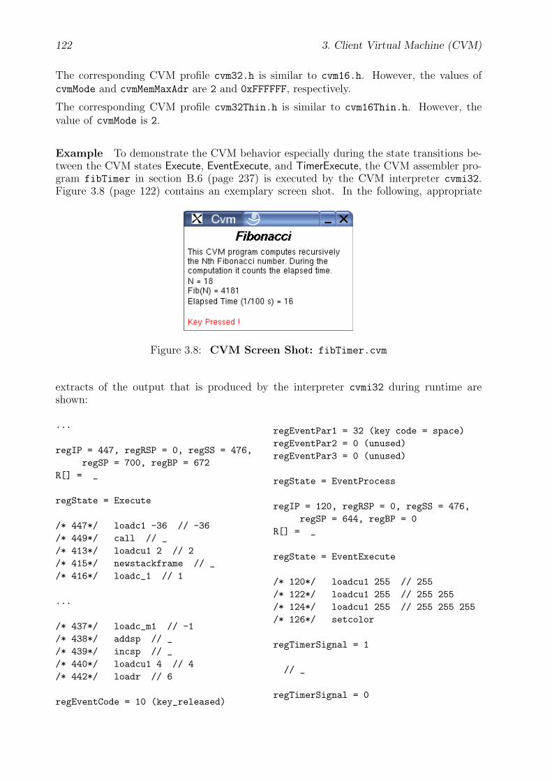
122 3. Client Virtual Machine (CVM)
The corresponding CVM profile cvm32.h is similar to cvm16.h. However, the values ofcvmMode and cvmMemMaxAdr are 2 and 0xFFFFFF, respectively.
The corresponding CVM profile cvm32Thin.h is similar to cvm16Thin.h. However, thevalue of cvmMode is 2.
Example To demonstrate the CVM behavior especially during the state transitions be-tween the CVM states Execute, EventExecute, and TimerExecute, the CVM assembler pro-gram fibTimer in section B.6 (page 237) is executed by the CVM interpreter cvmi32.Figure 3.8 (page 122) contains an exemplary screen shot. In the following, appropriate
Figure 3.8: CVM Screen Shot: fibTimer.cvm
extracts of the output that is produced by the interpreter cvmi32 during runtime areshown:
...
regIP = 447, regRSP = 0, regSS = 476,regSP = 700, regBP = 672
R[] = _
regState = Execute
/* 447*/ loadc1 -36 // -36/* 449*/ call // _/* 413*/ loadcu1 2 // 2/* 415*/ newstackframe // _/* 416*/ loadc_1 // 1
...
/* 437*/ loadc_m1 // -1/* 438*/ addsp // _/* 439*/ incsp // _/* 440*/ loadcu1 4 // 4/* 442*/ loadr // 6
regEventCode = 10 (key_released)
regEventPar1 = 32 (key code = space)regEventPar2 = 0 (unused)regEventPar3 = 0 (unused)
regState = EventProcess
regIP = 120, regRSP = 0, regSS = 476,regSP = 644, regBP = 0
R[] = _
regState = EventExecute
/* 120*/ loadcu1 255 // 255/* 122*/ loadcu1 255 // 255 255/* 124*/ loadcu1 255 // 255 255 255/* 126*/ setcolor
regTimerSignal = 1
// _
regTimerSignal = 0

3.11. Related Work 123
regIP = 459, regRSP = 0, regSS = 476,regSP = 644, regBP = 0
R[] = _
regState = TimerExecute
/* 459*/ loadc_0 // 0/* 460*/ loada // 207/* 461*/ inc // 208/* 462*/ loadc_0 // 208 0/* 463*/ storea // _/* 464*/ loadc_0 // 0/* 465*/ loada // 208/* 466*/ loadcu1 148 // 208 148/* 468*/ loadcu1 116 // 208 148 116/* 470*/ loadcu1 7 // 208 148 116 7/* 472*/ lib /*printIntBg*/ // _/* 473*/ halt // _
regIP = 127, regRSP = 0, regSS = 476,regSP = 644, regBP = 0
R[] = _
regState = EventExecute
/* 127*/ loadcu1 4 // 4/* 129*/ loadcu1 147 // 4 147/* 131*/ textbg "Key Pressed !" //
_/* 146*/ loadc_0 // 0/* 147*/ loadc_0 // 0 0/* 148*/ loadc_0 // 0 0 0/* 149*/ setcolor // _/* 150*/ halt // _
regIP = 443, regRSP = 1, regSS = 476,regSP = 644, regBP = 620
R[] = 6
regState = Execute
/* 443*/ loadcu1 2 // 6 2/* 445*/ sub // 4/* 446*/ push // _/* 447*/ loadc1 -36 // -36/* 449*/ call // _
...
Note the state transitions ... → Execute → EventProcess → EventExecute → TimerExecute→ EventExecute→ Execute→ ... in the output. They occur when a timer signal interruptsexecution of an event handling subroutine, whereas the corresponding event in turn haspreviously interrupted normal execution of the CVM.
3.11 Related Work
JVM The main analogies and differences between the JVM [80] from Sun Microsystemsand the CVM are listed in the following table:
JVM CVM
Main Architecture:
object oriented not object oriented
only core functionality; anything elsevia Java APIs
Core module provides core functional-ity; additional modules for Visual, Au-dio, Network, etc., each with appropri-ate CVM instructions, e.g., basic draw-ing instructions of the Visual module;module Library contains CVM librariesfor more complex tasks.
Data Types:
byte Int1
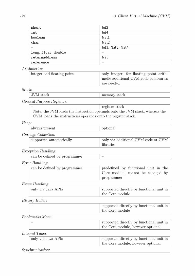
124 3. Client Virtual Machine (CVM)
short Int2
int Int4
boolean Nat1
char Nat2
– Int3, Nat3, Nat4
long, float, double –
returnAddress Nat
reference –
Arithmetics:
integer and floating point only integer; for floating point arith-metic additional CVM code or librariesare needed
Stack:
JVM stack memory stack
General Purpose Registers:
– register stackNote, the JVM loads the instruction operands onto the JVM stack, whereas theCVM loads the instructions operands onto the register stack.
Heap:
always present optional
Garbage Collection:
supported automatically only via additional CVM code or CVMlibraries
Exception Handling:
can be defined by programmer –
Error Handling:
can be defined by programmer predefined by functional unit in theCore module, cannot be changed byprogrammer
Event Handling:
only via Java APIs supported directly by functional unit inthe Core module
History Buffer:
– supported directly by functional unit inthe Core module
Bookmarks Menu:
– supported directly by functional unit inthe Core module, however optional
Interval Timer:
only via Java APIs supported directly by functional unit inthe Core module, however optional
Synchronization:

3.11. Related Work 125
via monitors via test and set instructions (testsetbits,unsetbits)
Binary Executable Format:
Java Class File CVM Packet; much simpler format
complex verification process simple verification process, checksmainly whether a CVM packet com-plies to the CVM packet format andto the system properties given by theCVM profile.
constant pool data sectionNote, in addition to the numeric and string constants known at compile time, theconstant pool also contains method and field references that must be resolvedat run time by the JVM (dynamic linking). The constant pool is similar to asymbol table for a conventional programming language.
Table 3.1: Comparison: JVM ↔ CVM
J2ME: CLDC, MIDP A J2ME [74] enabled, mobile low-end device has to implementat least both CLDC [73] and MIDP [78]. The proposed CVM represents an alternativeto the CLDC/MIDP platform. The main differences of CLDC/MIDP and the CVM arelisted in the following:
The KVM executable from the CLDC Reference Implementation Version 1.1 for a Linuxplatform requires about 280 Kbytes, whereas the CVM executable from this implementa-tion requires only about 70 Kbytes.
The memory requirements of CLDC/MIDP are much higher than of the CVM. For example,at least 128 Kbytes volatile memory for the Java runtime (e.g., Java heap) are required.However, the CVM can work properly with even less than 1 Kbyte of volatile memory aslong as the CVM packet server generates such small CVM packets that do not need toomuch additional memory for storing runtime data.
CLDC/MIDP is not as flexible as the CVM, because it can not be modularized like theCVM. A CLDC/MIDP enabled device has to implement all parts of it. Besides, the systemrequirements of CLDC/MIDP are higher than that of the CVM. The CVM, however hasa modular architecture with optional components and reports its system properties andcapabilities to the CVM packet server within a CVM profile.
WAP: WML, WMLScript, UAProf The client user interface language WML [56]is descriptive and therefore more difficult to interpret than CVM code which is opera-tional. Therefore, WML has to include WMLScript [58] for dynamic tasks, which ad-ditionally requires a WMLScript interpreter that runs on the client device. The CVMcode format does not need any other client languages. It enables more scalability thanWML/WMLScript when desribing user interfaces. As it provides at least equal func-tionality, WML/WMLScript documents might be translated with a given CVM profilecompletely into appropriate CVM packets.
126 3. Client Virtual Machine (CVM)
UAProf [59] is the WAP counterpart of the CVM profile. Both formats are binary. UAProfprovides a rich vocabulary set to describe the client capabilities from the hardware levelup to the application level, whereas the CVM profile focuses mainly on the configurationand special characteristics of the CVM and on the user preferences. The UAProf compo-nent “HardwarePlatform” contains some attributes that are identical or similar to someprofile items in the CVM profile, e.g., Keyboard and ScreenSize. However, it does nothave attributes that describe the memory size and supported fonts of the client device asprecisely as the CVM profile item codes cvmMemMaxAdr and cvmFonts. All in all, theCVM profile describes the hardware capabilities of the client device a little more detailedand at a slightly lower level.
Nevertheless, some UAProf attributes might be adopted for the CVM profile in the future,if required.
W3C: XHTML Basic, XML, CSS, XSL, XForms, CC/PP As XHTML Basic [8] isa subset of HTML [65], it is still declarative with high-level markup elements and thereforelacks of the same disadvantages as HTML in terms of scalability and functionality. Thesedisadvantages are discussed in detail in section 2.2 (page 13).
CSS [12] and XSL [2] are very powerful languages to describe the layout structure of anXML [16] document. However, they are too complex to be interpreted by a resource-constrained client device. CSS Mobile Profile [95] contains some simplifications, but stillthe client device needs to perform the formatting task on its own by a rendering enginethat runs on the client device.
XForms [24] is a powerful language to describe user interfaces. However, as XForms isa declarative and a quite high-level language, the task of interpreting and rendering anXForms document might be too complex for a resource-constrained client device. Allevia-tions for restricted client devices have not been defined, so far.
As the CC/PP Profile is based on XML [16] and RDF [44], it is more complex than theCVM profile that is proposed in this thesis. The CC/PP Exchange Protocol [53] assumes anunderlying application protocol such as HTTP [10], whereas the proposed CPTP protocolruns directly on top of the transport service. In addition, the CC/PP framework doesnot define a new virtual machine that acts as the user agent. As the CC/PP attributevocabulary is similar to UAProf for the WAP Forum, refer also to the comments on UAProfin section 3.11 (page 126).
To sum up, all the XML-based technologies such as XHTML Basic, XML, CSS, XSL, andXForms provide less scalability when describing user interfaces and impose more systemrequirements for the client device than the proposed CVM approach. However, they mightbe used as user-friendly front ends to specify documents and user interfaces on the serverside. With a given CVM profile, the CVM packet generator might transform these front-end specifications into appropriate CVM packets.

Chapter 4
CVM Packet Transfer Protocol(CPTP)
The CVM packet transfer protocol (CPTP) is an application protocol that manages thecommunication between the CVM and the CVM packet server. It runs on top of thetransport layer and is a very “thin” counterpart to the HTTP [10] application protocol inthe World Wide Web (WWW). HTTP was developed especially for the WWW and has alot of advanced and complex protocol aspects for caching, authorization, handling of serverresponse codes and error conditions, etc., which are quite hard to implement on a resourcelimited client. With the request headers Accept, Accept-Charset, Accept-Encoding,and Accept-Language, HTTP also covers some aspects of content negotiation — howeverat a high level of abstraction, i.e., no detailed description of the hardware capabilities ofthe client device, but a few directives on the preferred document formats, character sets,content encodings, and language. The HTTP equivalent of the WAP protocol stack isthe Wireless Session Protocol [57] (WSP). However, this protocol provides full HTTP 1.1functionality and additionally incorporates some other features.
In contrast, CPTP provides only a few basic protocol methods for requesting and deliveringCVM packets, for sending CVM profile data that is used for content negotiation, for sendingarbitrary data that is processed on the server side, and for reporting error messages. Theadvanced and complex protocol aspects like the handling of all kinds of server responsecodes and error conditions are not specified by the CPTP protocol. Instead, the CVMpacket server might send in such a situation an appropriate CVM packet to the CVM thatcontains a user interface which informs the user and also provides a list of actions howthe user can react to that server response. As a result, these application-specific protocolaspects are dealt with on the server side by the control logic of the network service. TheCVM is not required to interpret such server responses on its own, i.e., generate appropriateuser interfaces and perform appropriate actions on its own, as it is the case with the HTTPprotocol. An example of an error condition might be when the CVM requests a nonexistentuser interface page from a CVM packet server.
4.1 Message Format
Each CPTP message consists of a protocol method and possibly some operands, calledmessage items. Its binary format is presented here as a tuple data structure by using the
127

128 4. CVM Packet Transfer Protocol (CPTP)
generally understandable notation from section A.3 (page 208). Successive componentswithin a tuple or array structure are stored in a CPTP message sequentially, withoutpadding or alignment. Multibyte values are stored in big-endian order. Refer to section3.1.1 (page 32) for more information on the CVM data types Nat<1|...|4>. The array typeNat1[ ] is used for byte streams of any data. The general binary format of a CPTP messageis as follows:
CptpMessage = { Nat1 methodCode;Nat1[4] sessionId;Nat1 cvmIntLen;Nat1[ ] messageItems }
methodCode is a unique integer number that identifies the protocol method and thus thedesired CPTP operation. In contrast to the HTTP [10] protocol, all CPTP protocolmethods are encoded as binary values, but not as a sequence of ASCII characters.
sessionId identifies the current client-server session. A CVM packet server might servemore than one CVM at the same time and therefore needs this value to distinguish betweenthem when it receives a CPTP message from a CVM. (Note that the IP [62] address of theCVM is not sufficient, because — as the case may be — several CVM processes may run onthe same client host, each having a session with the same CVM packet server.) Each time,the CVM sends a CPTP message to a CVM packet server, it writes the current value ofregSessionId into this message item. Each time, the CVM receives a CPTP message from aCVM packet server, it stores the value of sessionId into its special register regSessionId.Refer to section 3.4 (page 82) for more information on regSessionId. At the beginning of anew client-server session, the value of sessionId is zero in the GET message from a CVMto the CVM packet server. The CVM packet server then assigns a value other than zeroto the new session and uses this value for the message item sessionId in its responsemessage. As a result, the CVM packet server can determine which CPTP message belongsto which client-server session.
With a 4-byte value each CVM packet server can serve 232 − 1 clients at same time.However, if necessary, a 6- or 8-byte value might be used in the future.
cvmIntLen reports to the CVM packet server the value of cvmIntLen, which depends onthe CVM mode of the CVM. Refer to section 3.1.2 (page 33) for more information oncvmIntLen and on CVM modes.
messageItems is a possibly empty array of data values which depend on the protocolmethod.
All protocol methods and their message items are listed in the next section.
4.2 Protocol Methods
In the following, the currently specified CPTP protocol methods are listed alphabeticallyand described using the following description format:
method name = methodCode: messageItems
method name is the verbose name of the methodCode. messageItems is specified as a tuple
4.2. Protocol Methods 129
structure. Depending on the method code, however, it may also be empty.
The data type Nat is used as a shortcut for the data type Nat<cvmIntLen>.
Additional protocol methods may be defined in the future. A client-server session alwaysstarts with a GET message which is sent from the CVM to a CVM packet server.
CVMP = 1: { Nat cvmpNo, pageMemAdr; CVMPacket cvmPacket }This protocol method is used by the CVM packet server when it sends the CVM packetcvmPacket to the CVM. Refer to section 3.8 (page 93) for more information on the CVMpacket format. cvmpNo contains the number of this CVM packet. A CVM packet containsone or more CVMUI pages. Refer to sections 2.3 (page 27) and 5.5 (page 166) for moreinformation on CVM user interfaces. pageMemAdr contains the absolute memory addressof the CVM instruction, where the CVM should start execution, after it has loaded thisCVM packet into its memory. Generally, this memory address represents the beginningof the instruction block of a particular CVMUI page. The CVM does not respond to areceived CVMP message.
ERROR = 2: { Nat1 errorCode; Nat memAdr } |{ Nat1 errorCode }
This protocol method is used by the CVM and the CVM packet server to report errors. Ifthe CVM or the CVM packet server receives an ERROR message, it does not respond to it.Two tuple structures for the message items are possible:
The first tuple structure is used only by the CVM. If the CVM encounters an error whileprocessing and executing a received CVM packet, it sends an ERROR message to the CVMpacket server from which the CVM packet comes from. Refer also to section 3.1.5.1 (page41) and to the CVM state transitions in section 3.1.10 (page 58), especially to the stateError. The message items errorCode and memAdr refer to the current values of the spe-cial registers regErrorCode and regIP, respectively. They report which error has occurredand where in the CVM program. However, if the value of the message item errorCode
is MalformedCPTPMessage or UnexpectedCPTPMethodCode, the value of the message itemmemAdr is not relevant. Refer also to section 3.1.5.2 (page 43) for more information on theerror codes MalformedCPTPMessage and UnexpectedCPTPMethodCode. The CVM packetserver might collect the received ERROR messages to enable bug-fixes by the server admin-istrators, afterwards.
The second tuple structure is used only by the CVM packet server. Then, the messageitem errorCode might only have the value MalformedCPTPMessage, MalformedCVMProfile,or UnexpectedCPTPMethodCode:
It has the value MalformedCPTPMessage, if the CVM packet server receives a malformedCPTP message from the CVM. Refer also to section 3.1.5.2 (page 43) for more informationon the error code MalformedCPTPMessage.
It has the value MalformedCVMProfile, when the CVM packet server receives a malformedCVM profile from the CVM. Refer to section 3.7 (page 89) for more information on theCVM profile format. Note that a CVM profile may be malformed, even if the entireCPTP message is well-formed. For example, the given profile item values might not fittogether. Refer also to section 3.1.5.2 (page 43) for more information on the error codeMalformedCVMProfile.

130 4. CVM Packet Transfer Protocol (CPTP)
It has the value UnexpectedCPTPMethodCode, if the CVM packet server receives a CPTPmessage with an unexpected protocol method (methodCode). For example, if the CVMpacket does not receive a GET message from the CVM at the beginning of a client-serversession. Refer also to section 3.1.5.2 (page 44) for more information on the error codeUnexpectedCPTPMethodCode.
GET = 3: { Nat serviceNo, pageNo, subpageNo; CVMProfile cvmProfile;Nat numBytes; Nat1[numBytes] dataBytes }
This protocol method is similar to the GET and POST methods of the HTTP [10] protocol.It is used by the CVM to send the data in the data array dataBytes to the CVM packetserver and then request from it the CVMUI page that is addressed by the page numberpageNo and the subpage number subpageNo. serviceNo refers to the current value of thespecial register regServiceNo. It contains the number of the interactive network servicethat is requested by the CVM. pageNo and subpageNo each contain an unsigned integernumber. They refer to a particular CVMUI page that belongs to the interactive networkservice with the number serviceNo. Refer to sections 2.3 (page 27) and 5.5 (page 166)for more information on CVM user interfaces. cvmProfile reports to the CVM packetserver the capabilities of the CVM and also the currently active user preferences. TheCVM packet server then passes these informations to the CVM packet generator whichcreates appropriate CVM packets for the CVM. Refer to section 3.7 (page 89) for moreinformation on the CVM profile format.
The CVM only sends a GET message to the CVM packet server, when it encounters the rcvor sendrcv instruction, or when the user of the client device has successfully raised a builtinevent such as history back, history forward, history reload, menu bookmarks, or input hostAdr.However, numBytes is always zero unless the CVM has encountered the sendrcv instruction.Refer also to the CVM state transitions in section 3.1.10 (page 58), especially to the statesEventExecute, Execute, TimerExecute, EventProcessBuiltin, and CptpGET.
Depending on the situation, the CVM packet server might respond with a CVMP, PROFILE,or an ERROR message: If everything goes well with CVM packet generation, it respondswith a CVMP message to send the CVM packet that contains the requested CVMUI pageto the CVM. If the CVM profile is not complete and the CVM packet generator needsmore information on the client capabilities and user preferences, the CVM packet serverresponds with a PROFILE message that lists the required profile item values. After successfulcontent negotiation, the CVM packet server finally sends to the CVM a CVMP messagethat contains the requested CVMUI page. However, if the CVM profile cvmProfile ismalformed, the CVM packet server responds with an ERROR message with the errorCode
MalformedCVMProfile.
Note that it is left to the implementors’ choice whether the CVM always sends a completeCVM profile which contains all profile item values within the GET message. For example,the CVM could instead send in the GET message only its cvmMode and profileId. If theCVM packet server needs more information, it can ask the CVM for particular profile itemvalues by sending a PROFILE message to the CVM where it lists all the needed profileitem values. The CVM then responds with a PROFILE message that contains all requestedprofile item values.
4.3. Implementation Notes 131
PROFILE = 4: { CVMProfile cvmProfile } |{ Nat1[ ] profileItemCodes; Nat1 0 }
This protocol method is used by the CVM and the CVM packet server for content negotia-tion. Two tuple structures for the message items are possible: The first one is used only bythe CVM whereas the second one is used only by CVM packet server. If during a request,which is initiated by the CVM with a GET message, the CVM packet server needs someparticular profile item values of the CVM, it sends a PROFILE message to the CVM and listsall desired profile item codes in the data array profileItemCodes. Refer to section 3.7(page 90) for a list of all currently defined profile item codes. As all profile item codes aregreater than zero, the end of the list is marked by the value zero. If the CVM packet serverneeds all profile item values, then profileItemCodes is empty. The CVM then respondswith a PROFILE message and sends a CVMProfile structure that contains the values forall desired profile item codes. Refer to section 3.7 (page 89) for more information on theCVM profile format.
Note that PROFILE messages are only sent during a request, i.e., between a GET messagefrom the CVM to the CVM packet server and a CVMP message from the CVM packet serverto the CVM, and only when it is necessary. In addition, the CVM only sends a PROFILE
message to the CVM packet server, after it has received a PROFILE message from the CVMpacket server.
4.3 Implementation Notes
The CPTP application protocol has been implemented on top of the TCP/IP [69] protocolstack. The reserved port number is 60507.
The client part of the CPTP protocol belongs to the CVM module Network. The cor-responding source files cptpClient.{h,c} are located in the subdirectory Implementa-
tion/Cvm/Src/Network/. Refer to section 3.10 (page 117) for more information on theentire CVM implementation.
The server part of the CPTP protocol is implemented by the source files cptp.h andcptpServer.{h,c} which are located in the subdirectory Implementation/CvmPacket-
Server/Src/. Refer to section 5.6 (page 198) for more information on the entire CVMpacket server implementation.
For the implementation of the TCP/IP [69] network communication the Linux socketinterface, which is compatible to the BSD [17] socket interface, has been used. However,this implementation supports only IPv4, but not IPv6.
4.4 Example
The use of the protocol methods will be demonstrated by an example session that isillustrated in figure 4.1 (page 132). Let there be a CVM client with the CVM profile
{ cvmMode = 16Bit;profileId = 483721;cvmNumGeneralRegs = 10;
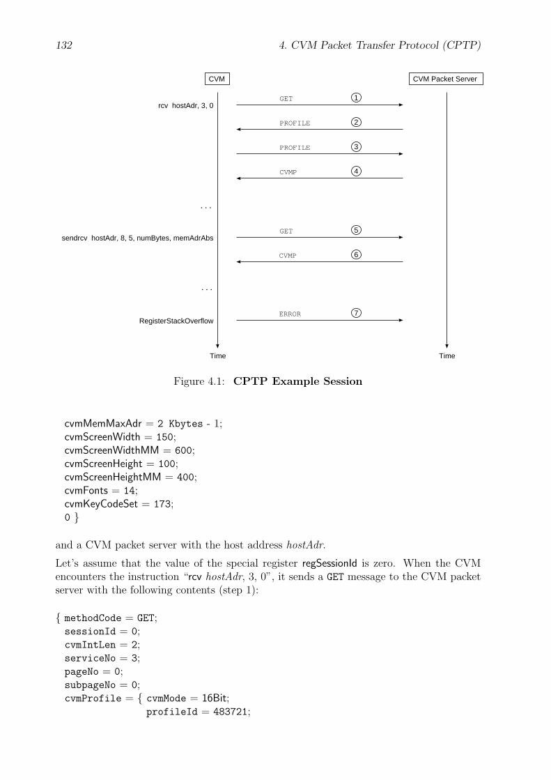
132 4. CVM Packet Transfer Protocol (CPTP)
CVM CVM Packet Server
rcv hostAdr, 3, 0GET 1
PROFILE 2
PROFILE 3
CVMP 4
ERROR 7
...
...
RegisterStackOverflow
sendrcv hostAdr, 8, 5, numBytes, memAdrAbsGET 5
CVMP 6
TimeTime
Figure 4.1: CPTP Example Session
cvmMemMaxAdr = 2 Kbytes - 1;cvmScreenWidth = 150;cvmScreenWidthMM = 600;cvmScreenHeight = 100;cvmScreenHeightMM = 400;cvmFonts = 14;cvmKeyCodeSet = 173;0 }
and a CVM packet server with the host address hostAdr.
Let’s assume that the value of the special register regSessionId is zero. When the CVMencounters the instruction “rcv hostAdr, 3, 0”, it sends a GET message to the CVM packetserver with the following contents (step 1):
{ methodCode = GET;sessionId = 0;cvmIntLen = 2;serviceNo = 3;pageNo = 0;subpageNo = 0;cvmProfile = { cvmMode = 16Bit;
profileId = 483721;

4.4. Example 133
0 };numBytes = 0;dataBytes = [ ] }
As there is a new client request, which is indicated by the value of sessionId = 0, theCVM packet server first assigns a new value to this session. Let the value be in this example42. In addition, the CVM at first has not sent a complete CVM profile to the CVM packetserver where all profile item values are listed. However, here the CVM packet server doesnot have the profile item values for a CVM with the profileId = 483721 available in itsdatabase. Therefore, the CVM packet server has to ask the CVM for a detailed CVMprofile by sending a PROFILE message to it with the following contents (step 2):
{ methodCode = PROFILE;sessionId = 42;cvmIntLen = 2;0 }
The CVM then responds with the following PROFILE message (step 3):
{ methodCode = PROFILE;sessionId = 42;cvmIntLen = 2;cvmProfile = { cvmMode = 16Bit;
profileId = 483721;cvmNumGeneralRegs = 10;cvmMemMaxAdr = 2 Kbytes - 1;cvmScreenWidth = 150;cvmScreenWidthMM = 600;cvmScreenHeight = 100;cvmScreenHeightMM = 400;cvmFonts = 14;cvmKeyCodeSet = 173;0 }}
After the CVM packet generator has generated the CVM packets, the CVM packet serversends to the CVM the following CVMP message which contains the CVM packet with therequested CVMUI page (step 4).
{ methodCode = CVMP;sessionId = 42;cvmIntLen = 2;cvmpNo = 0;pageMemAdr = 2370;cvmPacket = ... }
When the CVM encounters the instruction “sendrcv hostAdr, 8, 5, numBytes, memAdrAbs”,it sends a GET message to the CVM packet server with the following contents (step 5):
134 4. CVM Packet Transfer Protocol (CPTP)
{ methodCode = GET;sessionId = 42;cvmIntLen = 2;serviceNo = 3;pageNo = 8;subpageNo = 5;cvmProfile = { cvmMode = 16Bit;
profileId = 483721;0 };
numBytes = numBytes ;dataBytes = [...] }
The CVM packet server first processes the received data in the data array dataBytes.Then it sends to the CVM the following CVMP message which contains the CVM packetwith the requested CVMUI page (step 7).
{ methodCode = CVMP;sessionId = 42;cvmIntLen = 2;cvmpNo = 5;pageMemAdr = 832;cvmPacket = ... }
At the end, the error RegisterStackOverflow occurs during the CVM executes the recentlyloaded CVM packet. The CVM then sends an ERROR message to the CVM packet serverto notify the CVM packet server. The ERROR message has the following contents (step 8):
{ methodCode = ERROR;sessionId = 42;cvmIntLen = 2;errorCode = regErrorCode;memAdr = regIP }
Note that in the normal case the CVM packet generator creates valid CVM packets, sothat no runtime errors should occur when the CVM executes the CVM packets.

Chapter 5
CVM Packet Server (CVMPS)
The CVM packet server processes the client requests and generates session instances andCVM packets that are optimized for the individual client capabilities. The client-servercommunication is determined by the CPTP protocol, which is specified in section 4 (page127). The client capabilities are described in the CVM profile. The CVM packet formatand the CVM profile format are specified in the sections 3.8 (page 93) and 3.7 (page 89),respectively.
Note that the service providers can freely choose the design and implementation of theirserver-side architecture as far as it conforms to the specified CVM packet format, theCVM profile format, and the CPTP communication protocol. As a proof of concept, aCVM packet server has been developed and implemented in this thesis as well. Its maincomponents are as follows:
• Abstract User Interface Description (AUI): The abstract user interface descriptionlanguage is used to specify interactive network services on the application layer.
• Session Manager: The session manager processes all incoming client messages andstores the data that are involved during the client-server sessions.
• Service Generator: The service generator generates the client-specific service instancefrom a given AUI description and CVM profile.
• CVM Packet Generator: The CVM packet generator generates customized CVMpackets from a given AUI description and CVM profile. These CVM packets arecalled CVM user interfaces.
• CVM User Interface (CVMUI): A CVM user interface is a CVM packet that isgenerated by the CVM packet generator from a given AUI description. It may containall parts of a given AUI page or only a smaller subset. Here an exemplary structureof a CVMUI is specified.
5.1 Abstract User Interface Description (AUI)
In this thesis an exemplary abstract user interface description language, called AUI, hasbeen developed and implemented. It is used to specify interactive network services on theapplication layer which consist of user interfaces for the CVM and state-dependent actions
135
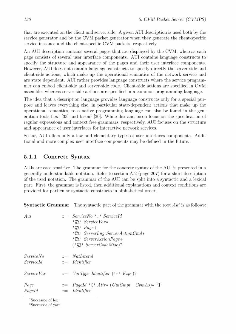
136 5. CVM Packet Server (CVMPS)
that are executed on the client and server side. A given AUI description is used both by theservice generator and by the CVM packet generator when they generate the client-specificservice instance and the client-specific CVM packets, respectively.
An AUI description contains several pages that are displayed by the CVM, whereas eachpage consists of several user interface components. AUI contains language constructs tospecify the structure and appearance of the pages and their user interface components.However, AUI does not contain language constructs to specify directly the server-side andclient-side actions, which make up the operational semantics of the network service andare state dependent. AUI rather provides language constructs where the service program-mer can embed client-side and server-side code. Client-side actions are specified in CVMassembler whereas server-side actions are specified in a common programming language.
The idea that a description language provides language constructs only for a special pur-pose and leaves everything else, in particular state-dependent actions that make up theoperational semantics, to a native programming language can also be found in the gen-eration tools flex† [33] and bison‡ [30]. While flex and bison focus on the specification ofregular expressions and context free grammars, respectively, AUI focuses on the structureand appearance of user interfaces for interactive network services.
So far, AUI offers only a few and elementary types of user interfaces components. Addi-tional and more complex user interface components may be defined in the future.
5.1.1 Concrete Syntax
AUIs are case sensitive. The grammar for the concrete syntax of the AUI is presented in agenerally understandable notation. Refer to section A.2 (page 207) for a short descriptionof the used notation. The grammar of the AUI can be split into a syntactic and a lexicalpart. First, the grammar is listed, then additional explanations and context conditions areprovided for particular syntactic constructs in alphabetical order.
Syntactic Grammar The syntactic part of the grammar with the root Aui is as follows:
Aui ::= ServiceNo ’,’ ServiceId’%%’ ServiceVar∗’%%’ Page+’%%’ ServerLng ServerActionCmd∗’%%’ ServerActionPage+(’%%’ ServerCodeMisc)?
ServiceNo ::= NatLiteralServiceId ::= Identifier
ServiceVar ::= VarType Identifier (’=’ Expr)?
Page ::= PageId ’{’ Attr∗ (GuiCmpt | CvmAs)∗ ’}’PageId ::= Identifier
†Successor of lex‡Successor of yacc
5.1. Abstract User Interface Description (AUI) 137
Attr ::= AttrName ’=’ Expr ’;’
GuiCmpt ::= GuiCmptType Identifier ’{’ Attr∗ Event∗ ’}’Event ::= EventType ’{’ CvmAsEntity∗ ’}’CvmAsEntity ::= ... // refer to section B.1 (page 216), “CvmAsEntity”
CvmAs ::= ’CvmAs’ ’{’ CvmAsEntity∗ ’}’
ServerActionCmd ::= ServiceCmdId ’:’ ’{’ ServerCode ’}’
ServiceCmdId ::= IdentifierServerCode ::= ...
ServerActionPage ::= (StatePageId ’,’)? StatePageId ’:’ ’{’ ServerCode ’}’
StatePageId ::= PageId | ’*’ | ’^’
ServerCodeMisc ::= ServerCode
Expr ::= MulExpr | Expr (’+’ | ’-’) MulExprMulExpr ::= Factor | MulExpr (’*’ | ’/’ | ’%’) FactorFactor ::= ’(’ Expr ’)’ | ’-’ Factor | NatLiteral | StringLiteral |
FontCode | ImgStyle | BuiltinFct ’(’ (Expr (’,’ Expr)∗)? ’)’ |AttrName | ’.’ AttrName | Identifier ’.’ AttrName |Identifier
Lexical Grammar The lexical part of the grammar is as follows:
GuiCmptType ::= ’Btn’ | ’Hlk’ | ’Ixt’ | ’Txp’ | ’Txt’EventType ::= ’evDwn’ | ’evUp’AttrName ::= ’x’ | ’y’ | ’w’ | ’h’ | ’fg’ | ’bg’ | ’fc’ | ’fs’ | ’str’ | ’yStr’ |
’strLenMax’ | ’hostAdr’ | ’serviceNo’ | ’img’ | ’imgStyle’ |’svIdx’
ImgStyle ::= ’imgTile’ | ’imgScale’VarType ::= ’Int’ | ’String’
ServerLng ::= ’C’ | ’C++’ | ’C#’ | ’Java’ | ...
BuiltinFct ::= ... // refer to section 5.1.3 (page 148), “builtin function name”FontCode ::= ... // refer to section 3.2.3 (page 79), “font code name”
Identifier ::= Alpha (Alpha | Digit )∗
NatLiteral ::= Digit+StringLiteral ::= ’"’ (ASCII \ ’"’)∗ (’\\"’ (ASCII \ ’"’)∗ )∗ ’"’
Alpha ::= ’a’..’z’ | ’A’..’Z’ | ’_’Digit ::= ’0’..’9’
WhiteSpace ::= ’ ’ | ’\f’ | ’\n’ | ’\r’ | ’\t’

138 5. CVM Packet Server (CVMPS)
Comment ::= ’/*’ ASCII∗ \ (ASCII∗ ’*/’ ASCII∗) ’*/’ |’//’ ASCII∗ \ (ASCII∗ ’\n’ ASCII∗) ’\n’
To resolve ambiguities within the lexical part of the grammar, the longest possible charactersequence of the AUI that matches one of the productions in the lexical grammar is selected.For example, the character sequence ’abc12’ is recognized as one Identifier, and not asthe Identifier ’abc’ followed by the NatLiteral ’12’. If the longest possible charactersequence matches more than one production, the production listed first is chosen.
White space characters (WhiteSpace) and comments (Comment) are discarded at lexicallevel. They may appear at any place in the AUI between the syntactic units listed in thesyntactic part of the grammar.
Attr An attribute definition consists of an attribute name (AttrName) and an integer ora string value that is specified by an expression (Expr).
• x, y, w, h: Expr must evaluate to an integer value that specifies the x, y coordinateposition or the width, height of a user interface component (GuiCmpt) in pixels,respectively. x and y define the coordinate position of the upper left corner of theuser interface component within the page (Page). The origin of the coordinate systemlies in the upper left corner of the page.
• fg, bg: Expr must evaluate to an integer value that specifies the foreground (fg) orbackground (bg) color of the page (Page) or user interface component (GuiCmpt).Refer also to the builtin function rgb in section 5.1.3 (page 149). Note that a userinterface component inherits the fg or bg value from the respective page (Page), if itdoes not specify its own fg or bg value, i.e., fg or bg does not appear in the attributelist (Attr∗) of the user interface component (GuiCmpt).
• fc, fs: Expr must evaluate to an integer value that specifies the font code (fc) orfont size (fs) of the text str which is displayed by the user interface component(GuiCmpt). Refer also to the font names in section 3.2.3 (page 79). Note that a userinterface component inherits the fc or fs value from the respective page (Page), ifit does not specify its own fc or bg value.
• str: Expr must evaluate to a string value that is displayed by the user interfacecomponent (GuiCmpt). If strLenMax is also specified, then the string value mayonly contain at most strLenMax characters. If str is not specified, then its defaultvalue is an empty string ("").
• yStr: Expr must evaluate to an integer value that defines the y coordinate position ofthe base line of the text str. Note that yStr may only be specified, if str is specifiedin the attribute list (Attr∗) as well. In addition, if yStr is specified, y must not bespecified at the same time, because its value is then derived from yStr, i.e., yStr =y + fontAscent(fc, fs) − 1 + dy . fontAscent is equivalent to the CVMA builtinfunction in section B.4 (page 229) of the same name and dy is an integer number(dy ≥ 0) that can be freely chosen by the CVM packet generator.
• strLenMax: Expr must evaluate to an integer value that specifies the maximumnumber of characters in the text str. This attribute must only be specified, if the
5.1. Abstract User Interface Description (AUI) 139
user interface component (GuiCmpt) gets text input from the user, e.g., Ixt. IfstrLenMax is specified, str must be specified in the attribute list (Attr∗) as well.
• hostAdr: Expr must evaluate to a string value that refers to the host address of aCVM packet server. The host address might be a DNS [45] name or an IP address[62] in standard dot notation.
• serviceNo: Expr must evaluate to an integer value that addresses the number of aservice that is offered by a particular CVM packet server. Refer also to ServiceNo(page 145).
• img: Expr must evaluate to a string value that contains the path of an image file,i.e., "Img/imgOK32x32.gif", or an empty string (""). If the string value is not anempty string, then the addressed image is rendered into the background area of thepage (Page) or user interface component (GuiCmpt). Otherwise, no image is drawn.If img is not specified, then its default value is "".
• imgStyle: Expr must evaluate to an integer value that specifies how the image img
is rendered into the background area of the respective page (Page) or user interfacecomponent (GuiCmpt). So far, only the following values are valid:
• 0: The image is tiled. The constant imgTile might be used as an alias.
• 1: The image is scaled. The constant imgScale might be used as an alias.
• 2: The image is displayed in its original size. The upper left corner of the imagelies in the upper left corner of the background area. That part of the image thatdoes not fit inside the background area is clipped. That part of the backgroundarea that is not covered by the image remains empty with the background colorof the area, which is specified by the attribute bg. The constant imgOrig mightbe used as an alias.
If imgStyle is not specified, then its default value is imgTile.
• svIdx: Expr must be an identifier (Identifier) that refers to a service variable(ServiceVar). This attribute applies only to interactive user interface components(GuiCmpt) that contain user data, e.g., Ixt. svIdx associates the user data of aninteractive user interface component with a service variable. Different user interfacecomponents of a page (Page) must not associate their user data with the same servicevariable, i.e., their svIdx attribute values must be different. Refer also to GuiCmpt(page 141) and ServiceVar (page 145).
The value of svIdx is the index number of the referenced service variable. If svIdx isnot specified, it must not be referenced in an expression (Expr). There is no defaultvalue for it.
For each page (Page) and user interface component (GuiCmpt) an attribute with a particu-lar name (AttrName) may be defined at least once. In addition, cyclic attribute definitionsare not allowed. Refer also to Page and GuiCmpt for attribute information that is specificfor Page and the different user interface components (GuiCmpt).
140 5. CVM Packet Server (CVMPS)
CvmAs CvmAs specifies CVM assembler code that is executed by the CVM. Usually,it contains additional data declarations and CVM instructions that are needed when theCVM executes the instructions (CvmAsEntity∗) specified in Event. Refer to section B(page 216) for more information on the CVM assembler.
Event Event specifies the behavior of a user interface component after an event of aparticular type (EventType) has occurred. Usually, an event occurs after the user of theCVM has performed some action, e.g., pressed a key or clicked a mouse button, etc.CvmAsEntity∗ contains CVM instructions that are executed then by the CVM.
Note that the AUI event types are not identical to the CVM event types. One or acombination of single CVM events may be mapped to a particular AUI event. It is left tothe CVM packet generator to determine which CVM events make up an AUI event. Referto section 3.1.6 (pages 45) for more information on CVM events.
So far, the AUI event types evDwn and evUp are defined. These events apply to the userinterface component Btn. The evDwn/evUp event occurs when the user presses/releases abutton with a mouse click or with a particular key stroke, e.g., the Blank or Return key, ifthe button currently has mouse or keyboard focus, i.e.,
evDwn ≡ mouse pressed left ∨key pressed enter ∨key pressed ∧ keyCode = XK space
evUp ≡ mouse released left ∨key released enter ∨key released ∧ keyCode = XK space
Note that several CVM events are already processed implicitly by the AUI components.For example the user interface component Hlk automatically starts a new request for thenetwork service that is specified by the attribute values hostAdr and serviceNo after anevDwn event occurs. In addition, the user interface component Ixt processes all the key andmouse events for text input and text editing implicitly. Moreover, the user might releaseor change the focus of the current user interface component and navigate to another onewith the following events:
“Focus Next”: key pressed ∧ keyCode = XK Tab
“Focus Previous”: key pressed ∧ keyCode = XK ISO Left Tab // Shift+Tab“Focus Release”: key pressed escape ∧ keyCode = XK ISO Left Tab // Shift+Tab
The CVM code for the implicit event processing is provided by the CVM packet generatorand also defined in the CVMUI libraries. Refer to section C (page 249) for more informationon CVMUI libraries. During event handling first the CVM instructions are executed thatare specified explicitly in the AUI description for a given user interface component and fora given event. If no explicit event behavior is specified, then the the implicit actions — ifavailable — are processed. For each user interface component (GuiCmpt) an event with aparticular type (EventType) may be defined at least once.
Additional event types for any user interface component types (GuiCmptType) may bedefined in the future.
5.1. Abstract User Interface Description (AUI) 141
Expr The value of an expression (Expr) might be an integer number or a string and isevaluated by the CVM packet generator during generation of CVMUIs.
If its value is a string, then the expression consists of a single string literal (StringLiteral),or of a single builtin function call (BuiltinFct) that returns a string, or of a single attributereference (AttrName | ’.’ AttrName | Identifier ’.’ AttrName) that refers to a stringvalue, or of a single identifier (Identifier) that refers to a service variable with a stringvalue, or of a concatenation of two string expressions with the ’+’ operator.
AttrName refers to the attribute (Attr) which has the same name AttrName and is specifiedin the attribute list (Attr∗) of the page (Page) or user interface component (GuiCmpt)where this expression (Expr) occurs.
The syntactic construct ’.’ AttrName refers to the attribute (Attr) which has the samename AttrName and is specified in the attribute list (Attr∗) of the page (Page).
The syntactic construct Identifier ’.’ AttrName refers to the attribute (Attr) which hasthe same name AttrName and is specified in the attribute list (Attr∗) of the user interfacecomponent (GuiCmpt) with the identifier Identifier.
A single identifier (Identifier) refers to a service variable (ServiceVar).
The values of BuiltinFct and FontCode are specified in the sections that are referred to inthe comments of the respective productions in the lexical grammar specification.
All arithmetic operations with integer numbers are based on integer but not floating pointarithmetic.
GuiCmpt GuiCmpt defines a user interface component. It consists of its type (GuiCmpt-Type), identifier (Identifier), attributes (Attr∗), and event behavior (Event∗).So far, there are the following different user interface component types:
• Txt: A Txt user interface component is used to display single-line text. The followingattributes apply to it: x, y, w, h, fg, bg, fc, fs, str, yStr.
Only the attributes that apply to the user interface component can be specified, i.e.,can appear in the attribute list (Attr∗). In addition, the following restrictions mustbe met:
– The attributes x, str, and either y or yStr must be specified, i.e., must appearin the attribute list (Attr∗).
– The attributes w and h must not be specified, because their values are derivedfrom str, fc, and fs.
• Txp: A Txp user interface component is used to display a text paragraph whichusually consists of several lines. The following attributes apply to it: x, y, w, h, fg,bg, fc, fs, str, yStr.
Only the attributes that apply to the user interface component can be specified, i.e.,can appear in the attribute list (Attr∗). In addition, the following restrictions mustbe met:
– The attributes x, w, str, and either y or yStr must be specified, i.e., mustappear in the attribute list (Attr∗). The attribute w specifies the width of thetext paragraph. The text is aligned and broken into several lines automatically.

142 5. CVM Packet Server (CVMPS)
– The attribute h must not be specified, because its value is derived from str, fc,fs, and the number of the lines in the text paragraph.
• Hlk: A Hlk user interface component is used to display a hyperlink that is similar toa hyperlink in HTML [65]. The following attributes apply to it: x, y, w, h, fg, bg,fc, fs, str, yStr, hostAdr, serviceNo.
Only the attributes that apply to the user interface component can be specified, i.e.,can appear in the attribute list (Attr∗). In addition, the following restrictions mustbe met:
– The attributes x, str, hostAdr, serviceNo, and either y or yStr must bespecified, i.e., must appear in the attribute list (Attr∗).
– The attributes w and h must not be specified, because their values are derivedfrom str, fc, and fs.
• Ixt: An Ixt user interface component is used to display a text box where the usercan input some text. The following attributes apply to it: x, y, w, h, fg, bg, fc, fs,str, yStr, strLenMax, svIdx.
Only the attributes that apply to the user interface component can be specified. Inaddition, the following restrictions must be met:
– The attributes x, w, str, strLenMax, and either y or yStr must be specified.
– The attribute h must not be specified, because its value is derived from fc andfs.
– The attribute svIdx is optional. If it is specified, the data type of the referencedservice variable (ServiceVar) must be String. Refer to section 3.1.1 (page 33)for more information on the CVM data type String.
The text that the user types in is stored into the attribute str and displayed imme-diately. At most strLenMax characters are stored, further characters are ignored. Asin any common text box the width of the text may be longer then w. The attributew defines the width of the text box and thus the clip area of the text that is visibleall at once.
svIdx associates the user data of this user interface component, which is stored inthe attribute str, with the given service variable. If svIdx is not specified, then theuser data of this user interface component is not associated with a service variable.So far, Ixt is the only interactive user interface component type that contains userdata. Additional interactive user interface component types with user data may bedefined in the future.
• Btn: A Btn user interface component is used to display a button. The button mustcontain text (str) or a background image (img) or both. The following attributesapply to it: x, y, w, h, fg, bg, fc, fs, str, yStr, img, imgStyle.
Only the attributes that apply to the user interface component can be specified. Inaddition, the following restrictions must be met:
– The attribute x must be specified always.
5.1. Abstract User Interface Description (AUI) 143
– If the button contains text, then the attributes str and either y or yStr mustbe specified as well. However, the attributes w and h must not be specified then,because their values are derived from str, fc, and fs.
– If the button does not contain text, i.e., the attribute str is not specified, thenthe attributes y, w, and h must be specified as well.
– If the button contains an image, then the attributes img and imgStyle must bespecified as well.
Refer also to Attr for more information on attributes. Note that user interface componentsof the type Btn, Hlk, or Ixt are interactive, as they receive user input. Refer also toEvent for more information on user interaction and event behavior of the user interfacecomponents.
In the future, additional (non-)interactive user interface component types may be defined,e.g., check boxes, combo boxes, list boxes, tables, etc.
Identifier Lexically, an identifier (Identifier) must not match GuiCmptType, EventType,AttrName, ImgStyle, VarType, ServerLng, BuiltinFct, FontCode, and ’CvmAs’. An iden-tifier is used to name the service (ServiceId), the service variables (ServiceVar), pages(PageId), and user interface component (GuiCmpt) when they are declared. The serviceidentifiers must be unique only for a particular CVM packet server. An identifier of aservice variable or page must be unique only within the identifiers of the other declaredservice variables or pages, respectively. An identifier of a user interface component must beunique only within the identifiers of the other declared user interface components withinthe same page.
NatLiteral If the positive integer number specified by NatLiteral exceeds the maximumvalue 231 − 1, it is truncated automatically to that limit by the CVM packet generator.
Page Page defines a complete AUI page. PageId is a unique page identifier and is usedwithin the AUI to refer to a particular page. Note that the CVM packet generator assignsto each page identifier a unique number greater than or equal to zero. This number is thenused by the CVM to address a particular page during a request. Refer also to the CVMinstructions rcv and sendrcv.
Attr contains an attribute definition. The following attributes apply to a page: x, y, w, h,fg, bg, fc, fs, img, imgStyle.
Only the attributes that apply to a page can be specified, i.e., can appear in the attributelist (Attr∗). However, the attributes x, y, w, and h must not be specified. Their valuescannot be changed and are by default always 0, 0, cvmScreenWidth, and cvmScreenHeight,respectively.
If the attributes fg, bg, fc, fs, img, and imgStyle are not specified, they are providedwith default values. These are rgb(0, 0, 0), rgb(255, 255, 255), fcFixedStandard,13, "", and imgTile, respectively.
GuiCmpt contains a graphical user interface component. CvmAs contains CVM assemblerinstructions that are executed by the CVM.
144 5. CVM Packet Server (CVMPS)
ServerActionCmd ServerActionCmd (”Server Action Command”) specifies actionsthat are executed on the server side, when the CVM requests a page. The CVM requests apage with the instructions rcv and sendrcv. A ServerActionCmd is identified by its uniqueServiceCmdId. The service generator assigns to each ServiceCmdId a unique index numbergreater than or equal to zero. During a client request the CVM packet server first checksthe dataBytes section of the GET request. The binary format of the dataBytes section isspecified in ServiceVar (page 146). When it encounters the index number (svcCmdIdx) ofa ServiceCmdId, it executes the actions (ServerCode) of the respective ServerActionCmdright after the dataBytes section of the GET request has been processed completely.
Refer also to the example in section 5.1.4 (page 149), to processDataBytes in section 5.2.2(page 157), and to svcInst actionsCmd in the sections 5.3.1 (page 160) and 5.3.2 (page161).
ServerActionPage ServerActionPage also specifies actions that are executed on theserver side, when the CVM requests a page. However, these actions are always executedafter the actions of a possibly referenced ServerActionCmd. The server-side actions ofServerActionPage are depending on the state of the client-server session which is given bythe following values:
• The number of the page that is currently executed by the CVM. This page is refer-enced by the first StatePageId. If the CVM starts requesting a page in the beginningof a client-server session, i.e., the CVM is currently not executing a page that belongsto this network service, then the first StatePageId is omitted or given as ’*’.
• The number of the page that is requested by the CVM. This page is referenced bythe second StatePageId.
The CVM packet server always stores for each CVM it serves the number of the page thatthe CVM is currently executing, i.e., the number of the previously sent page during theclient-server session. When the CVM requests a new page, the CVM packet server checksthe server actions (ServerActionPage+) from top to bottom to find the first rule whose firstStatePageId corresponds to the number of the page that the CVM is currently executing.If there is such a rule, the CVM packet server executes the actions within ServerCode andsends a new page to the CVM. Note that the number of the new page may be changedwithin ServerCode and therefore may be different than the number of the requested page,which is referred to by the second StatePageId.
In the very beginning of a client-server session, i.e., when the CVM makes a first request,the CVM packet server looks for the first rule where the first StatePageId is omitted orgiven as ’*’ which is a placeholder for any or no page. If StatePageId is specified by aPageId, then a page with the same name (PageId) must be defined in Page+.
Within ServerCode the following variable identifiers have special meanings:
• pageNow refers to the number of the previously sent page during the client-serversession. If there is no such page, which is the case in the beginning of a client-serversession, the value of pageNow is −1.
• pageReq refers to the number of the requested page.

5.1. Abstract User Interface Description (AUI) 145
• pageNext refers to the number of the page that is sent by the CVM packet serverto the client after the server-side actions have been processed. In the beginning ofthe server-side actions the value of pageNext is initialized each time with the valueof pageReq. Note that within ServerCode the value of pageNext may be changed.In the end of the server-side actions the value of pageNext is always checked. If itsvalue refers to a non-existing page number then its value is set to −1 and the CVMpacket server does not send any page to the client.
The number of an existing page with the identifier PageId is referred to by the termsvcInst PageId.
Refer also to the example in section 5.1.4 (page 149), and to svcInst actionsPage in thesections 5.3.1 (page 160) and 5.3.2 (page 161).
ServerCode ServerCode contains the instructions that are executed by the CVM packetserver. The used programming language for the server code is indicated by ServerLng.
ServerCodeMisc ServerCodeMisc contains additional declarations and definitions ofconstants, variables, and functions that are referenced in the instructions (ServerCode)of the server-side actions (ServerActionCmd, ServerActionPage). The used programminglanguage is indicated by ServerLng and is the same as the programming language that isused in ServerActionCmd and ServerActionPage.
ServerLng ServerLng indicates the programming language that is used to specify theserver-side actions (ServerCode). Note that the service providers can choose the program-ming language freely.
ServiceNo, ServiceId A CVM packet server might offer several network services. Eachservice is addressed by a number (ServiceNo) that is unique for a particular CVM packetserver. The ServiceId is just an descriptive alias name for the respective ServiceNo.
Note that for every CVM packet server the service number zero is always reserved for theservice that lists and describes all available services that are offered by the CVM packetserver. The user interface of this service also contains a menu for the user to select andstart a particular service.
ServiceVar ServiceVar declares a variable that stores a value during the client-serversession. In the following, these variables are called service variables. The service variablesare mainly used to store the values of the user interface components that take input fromthe user of the CVM, e.g., the input string of a text box control. Expr defines an initialvalue for a service variable. If VarType is Int then Expr might only consist of a singleinteger number. If VarType is String then Expr might only consist of a single stringliteral. If no initial value is specified explicitly, then the default value of a service variableis either 0 or “”.
The CVM packet generator assigns to each service variable a unique index number greaterthan zero and allocates for each service variable enough memory to store two values: itscurrent and saved value. In the beginning of a client-server session both values are equal.
146 5. CVM Packet Server (CVMPS)
The dataBytes section of a GET request overwrites only the current value of a servicevariable. Refer to section 4.2 (page 130) for more information on the CPTP protocolmethod GET. The binary format of the dataBytes section in the GET request is:
( { Nat<svIdxLen> svIdx; VarType svVal } |{ Nat<svIdxLen> 0; Nat2 svcCmdIdx } )∗
svIdx contains the index number of a particular service variable. svIdxLen is determinedby the CVM packet generator and may have the value 1, 2, or 4. Depending on thetotal number of service variables the smallest byte size, i.e., the smallest possible value forsvIdxLen, is used to specify the index numbers. If VarType is Int, then svVal representsan integer number and its binary format complies to a CVM integer number (Int) with thebyte length cvmIntLen. If VarType is String, then svVal represents a string and its formatcomplies to a CVM string (String). Refer to section 3.1.1 (page 32) for more informationon the CVM data types.
svcCmdIdx contains the index number of a ServiceCmdId. Refer to page 144 for moreinformation on ServiceCmdId and ServerActionCmd.
The values of the service variables can be accessed on the server side within the ServerCodeof the server actions (ServerActionCmd, ServerActionPage) for further processing. Notethat the precise syntax for accessing the service variables within the server actions neednot be specified here. This depends on the programming language (ServerLng) that isused for the server actions and is therefore left to the service providers. In the currentimplementation the service variables are accessed as follows:
• svcVarInt_get(svcVarId) returns the current integer (Int) value of the servicevariable with the Identifier svcVarId.
• svcVarInt_set(svcVarId, val) assigns the current integer value val to the servicevariable svcVarId, e.g., svcVarInt_set(var1, 18).
• svcVarStr_get(svcVarId) returns the current string (String) value of the servicevariable svcVarId.
• svcVarStr_set(svcVarId, val) assigns the current string value val to the servicevariable svcVarId, e.g., svcVarStr_set(var2, "hello world!").
• svcVar_reset() resets the current values of all service variables with their savedvalues.
• svcVar_save() saves the current values of all service variables, i.e., overwrites the(old) saved values with their current values.
Refer to the example in section 5.1.4 (page 149) for a demonstration of these server-sidefunctions.
The current and the saved value for each service variable is needed because of the followingreason: When the user navigates through the AUI subpages, the values of the user interfacecomponents that store user input are only saved as current values on the server-side. Thenthe user has the ability to reset all values of these controls to the latest saved values. Thecurrent values are only saved when the function svcVar save() is called on the server sidein ServerCode.
5.1. Abstract User Interface Description (AUI) 147
StatePageId StatePageId refers to a page. If it matches PageId, then it refers to aparticular page (Page) with the same identifier. If it matches ’*’, then it refers to anypage regardless of whether it has been defined in the AUI description. If it matches ’^’,then it refers to any page that has not been defined in the AUI description.
StringLiteral Refer to “StringLiteral” in section B.1 (page 222).
5.1.2 Abstract Syntax
The abstract syntax of the AUI grammar is specified as a data type definition with the rootAui. Refer to section A.3 (page 208) for a description of the used notation. The abstractsyntax is used in the following sections that describe the structure of the generated CVMcode from a given AUI description.
Aui = { Int serviceNo;String serviceId ;ServiceVar∗ serviceVars ;Page+ pages ;Int serverLng ;ServerActionCmd∗ serverActionsCmd ;ServerActionPage+ serverActionsPage;String serverCodeMisc }
ServiceVar = { String id ;Int varType;(Int | String) valInit }
Page = { String id ;Int pageNo, subpageNo;PageItem∗ pageItems }
PageItem = Attr | GuiCmpt | CvmAs
ServerActionCmd = { String idServiceCmd, serverCode }
ServerActionPage = { String idPageCurrent, idPageNext, serverCode }
GuiCmpt = { String id ;Int guiCmptType;GuiCmptItem∗ guiCmptItems }
GuiCmptItem = Attr | Event
Attr = { Int attrName;Expr expr }
Event = { Int eventType;String cvmAs }
148 5. CVM Packet Server (CVMPS)
CvmAs = { String cvmAs }
Expr = Add | Sub | Mul | Div | Rem | UnMinus |AttrRefLocal | AttrRefGuiCmpt | AttrRefPage |Id |BuiltinFct |IntLit | StrLit
Add = { Expr expr1, expr2 }Sub = { Expr expr1, expr2 }Mul = { Expr expr1, expr2 }Div = { Expr expr1, expr2 }Rem = { Expr expr1, expr2 }UnMinus = { Expr expr }BuiltinFct = { Int fctCode;
Expr∗ pars }AttrRefGuiCmpt = { Int attrName;
String idGuiCmpt }AttrRefLocal = { Int attrName }AttrRefPage = { Int attrName }Id = { String id }IntLit = { Int val }StrLit = { String val }
Note that if aui represents the abstract syntax tree after a given AUI description has beenparsed, then aui .pages [q ].pageNo := q ∧ aui .pages [q ].subpageNo := 0 (q ≥ 0). The tupleitem subpageNo is needed later for the numbering of the generated subpages of a givenAUI page, because the data type Page is also used to formally refer to an AUI subpage.Refer to section 5.2 (pages 154 ff.) for more information on AUI subpages.
5.1.3 Builtin Functions
For reasons of convenience, the AUI also provides some builtin functions to simplify spec-ifying user interfaces with AUI. The CVM packet generator processes a builtin functionduring it generates the corresponding CVMUI. In the following, the builtin functions arelisted alphabetically and described using the following description format:
builtin function name (parameters) : return typeverbose description
builtin function name serves as a one-word description of the purpose of the function. pa-rameters is a (comma separated and possibly empty) list of function parameters. Eachparameter is shown in the form identtype . ident can be any identifier and is usually chosento characterize the meaning of the parameter. type determines the syntactic type of theparameter according to the grammar specification in section 5.1.1 (page 136). The param-eter must match the production for type. For example, valExpr might be used to specifya value that matches the production for Expr. return type specifies the data type of theresult and is one of the CVM data types Int, Nat, String, or a tuple structure. Afterwards,a verbose description of the builtin function is given.
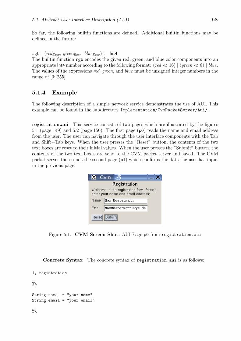
5.1. Abstract User Interface Description (AUI) 149
So far, the following builtin functions are defined. Additional builtin functions may bedefined in the future:
rgb (redExpr , greenExpr , blueExpr) : Int4The builtin function rgb encodes the given red, green, and blue color components into anappropriate Int4 number according to the following format: (red � 16) | (green � 8) | blue.The values of the expressions red, green, and blue must be unsigned integer numbers in therange of [0; 255].
5.1.4 Example
The following description of a simple network service demonstrates the use of AUI. Thisexample can be found in the subdirectory Implementation/CvmPacketServer/Aui/.
registration.aui This service consists of two pages which are illustrated by the figures5.1 (page 149) and 5.2 (page 150). The first page (p0) reads the name and email addressfrom the user. The user can navigate through the user interface components with the Taband Shift+Tab keys. When the user presses the ”Reset” button, the contents of the twotext boxes are reset to their initial values. When the user presses the ”Submit” button, thecontents of the two text boxes are send to the CVM packet server and saved. The CVMpacket server then sends the second page (p1) which confirms the data the user has inputin the previous page.
Figure 5.1: CVM Screen Shot: AUI Page p0 from registration.aui
Concrete Syntax The concrete syntax of registration.aui is as follows:
1, registration
%%
String name = "your name"String email = "your email"
%%
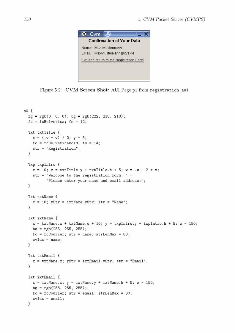
150 5. CVM Packet Server (CVMPS)
Figure 5.2: CVM Screen Shot: AUI Page p1 from registration.aui
p0 {fg = rgb(0, 0, 0); bg = rgb(222, 218, 210);fc = fcHelvetica; fs = 12;
Txt txtTitle {x = (.w - w) / 2; y = 5;fc = fcHelveticaBold; fs = 14;str = "Registration";
}
Txp txpIntro {x = 10; y = txtTitle.y + txtTitle.h + 5; w = .w - 2 * x;str = "Welcome to the registration form. " +
"Please enter your name and email address:";}
Txt txtName {x = 10; yStr = ixtName.yStr; str = "Name";
}
Ixt ixtName {x = txtName.x + txtName.w + 10; y = txpIntro.y + txpIntro.h + 5; w = 150;bg = rgb(255, 255, 255);fc = fcCourier; str = name; strLenMax = 80;svIdx = name;
}
Txt txtEmail {x = txtName.x; yStr = ixtEmail.yStr; str = "Email";
}
Ixt ixtEmail {x = ixtName.x; y = ixtName.y + ixtName.h + 5; w = 150;bg = rgb(255, 255, 255);fc = fcCourier; str = email; strLenMax = 80;svIdx = email;
}

5.1. Abstract User Interface Description (AUI) 151
Btn btnReset {x = txtName.x; y = ixtEmail.y + ixtEmail.h + 10;fg = rgb(51, 51, 51); bg = rgb(210, 218, 230);str = "Reset";
evDwn {fcall _svBufIdx_resetfcall_I _svBuf_svcCmd_write, svcCmd_Resetsendrcvpage_a _pageNo, _subpageNo
}}
Btn btnSubmit {x = btnReset.x + btnReset.w + 5; y = btnReset.y;fg = btnReset.fg; bg = btnReset.bg;str = "Submit";
evDwn {fcall _svBuf_writefcall_I _svBuf_svcCmd_write, svcCmd_Submitsendrcvpage _p1, 0
}}
}
p1 {fg = rgb(0, 0, 0); bg = rgb(222, 218, 210);fc = fcHelvetica; fs = 12;
Txt txtTitle {x = (.w - w) / 2; y = 5;fc = fcHelveticaBold; fs = 14;str = "Confirmation of Your Data";
}
Txt txtName {x = 10; y = txtTitle.y + txtTitle.h + 10;str = "Name:";
}
Txt txtNameVal {x = txtName.x + txtName.w + 10; y = txtName.y;str = name;
}
Txt txtEmail {x = txtName.x; y = txtName.y + txtName.h + 5;str = "Email:";
}
Txt txtEmailVal {
152 5. CVM Packet Server (CVMPS)
x = txtNameVal.x; y = txtEmail.y;str = email;
}
Hlk hlkService {x = txtEmail.x; y = txtEmail.y + txtEmail.h + 10;str = "Exit and return to the Registration Form";hostAdr = "127.0.0.1";serviceNo = 1;
}}
pNotExist {fg = rgb(0, 0, 0); bg = rgb(222, 218, 210);
Txt txtErrMsg {x = (.w - w) / 2; y = 5;str = "Requested page does not exist";
}}
pIllegal {fg = rgb(0, 0, 0); bg = rgb(222, 218, 210);
Txt txtErrMsg {x = (.w - w) / 2; y = 5;str = "Illegal page request";
}}
%% C
svcCmd_Reset:{printf("svcCmd_Reset\n");svcVar_reset();printf("name = \"%s\", email = \"%s\"\n",
svcVarStr_get("name"), svcVarStr_get("email"));}
svcCmd_Submit:{printf ("svcCmd_Submit\n");svcVar_save();printf("name = \"%s\", email = \"%s\"\n",
svcVarStr_get("name"), svcVarStr_get("email"));}
%%
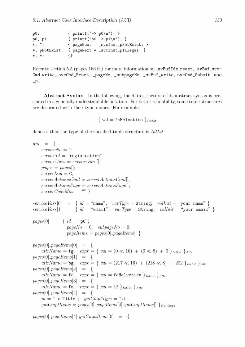
5.1. Abstract User Interface Description (AUI) 153
p0: { printf("-> p0\n"); }p0, p1: { printf("p0 -> p1\n"); }*, ^: { pageNext = _svcInst_pNotExist; }*, pNotExist: { pageNext = _svcInst_pIllegal; }*, *: {}
Refer to section 5.5 (pages 166 ff.) for more information on svBufIdx reset, svBuf svc-
Cmd write, svcCmd_Reset, _pageNo, _subpageNo, _svBuf_write, svcCmd_Submit, and_p1.
Abstract Syntax In the following, the data structure of its abstract syntax is pre-sented in a generally understandable notation. For better readability, some tuple structuresare decorated with their type names. For example,
{ val = fcHelvetica }IntLit
denotes that the type of the specified tuple structure is IntLit.
aui = {serviceNo = 1;serviceId = “registration”;serviceVars = serviceVars [];pages = pages [];serverLng = C;serverActionsCmd = serverActionsCmd [];serverActionsPage = serverActionsPage[];serverCodeMisc = “” }
serviceVars [0] = { id = “name”; varType = String; valInit = “your name” }serviceVars [1] = { id = “email”; varType = String; valInit = “your email” }
pages [0] = { id = “p0”;pageNo = 0; subpageNo = 0;pageItems = pages [0] pageItems [] }
pages [0] pageItems [0] = {attrName = fg; expr = { val = (0� 16) + (0� 8) + 0 }IntLit }Attr
pages [0] pageItems [1] = {attrName = bg; expr = { val = (217� 16) + (218� 8) + 202 }IntLit }Attr
pages [0] pageItems [2] = {attrName = fc; expr = { val = fcHelvetica }IntLit }Attr
pages [0] pageItems [3] = {attrName = fs; expr = { val = 12 }IntLit }Attr
pages [0] pageItems [4] = {id = “txtTitle”; guiCmptType = Txt;guiCmptItems = pages [0] pageItems [4] guiCmptItems [] }GuiCmpt
pages [0] pageItems [4] guiCmptItems [0] = {
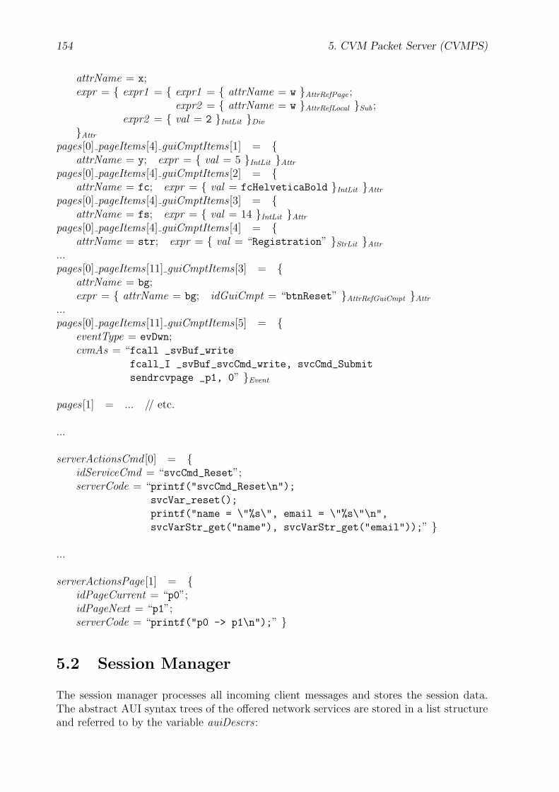
154 5. CVM Packet Server (CVMPS)
attrName = x;expr = { expr1 = { expr1 = { attrName = w }AttrRefPage ;
expr2 = { attrName = w }AttrRefLocal }Sub ;expr2 = { val = 2 }IntLit }Div
}Attr
pages [0] pageItems [4] guiCmptItems [1] = {attrName = y; expr = { val = 5 }IntLit }Attr
pages [0] pageItems [4] guiCmptItems [2] = {attrName = fc; expr = { val = fcHelveticaBold }IntLit }Attr
pages [0] pageItems [4] guiCmptItems [3] = {attrName = fs; expr = { val = 14 }IntLit }Attr
pages [0] pageItems [4] guiCmptItems [4] = {attrName = str; expr = { val = “Registration” }StrLit }Attr
...pages [0] pageItems [11] guiCmptItems [3] = {
attrName = bg;expr = { attrName = bg; idGuiCmpt = “btnReset” }AttrRefGuiCmpt }Attr
...pages [0] pageItems [11] guiCmptItems [5] = {
eventType = evDwn;cvmAs = “fcall _svBuf_write
fcall_I _svBuf_svcCmd_write, svcCmd_Submit
sendrcvpage _p1, 0” }Event
pages [1] = ... // etc.
...
serverActionsCmd [0] = {idServiceCmd = “svcCmd_Reset”;serverCode = “printf("svcCmd_Reset\n");
svcVar_reset();
printf("name = \"%s\", email = \"%s\"\n",
svcVarStr_get("name"), svcVarStr_get("email"));” }
...
serverActionsPage[1] = {idPageCurrent = “p0”;idPageNext = “p1”;serverCode = “printf("p0 -> p1\n");” }
5.2 Session Manager
The session manager processes all incoming client messages and stores the session data.The abstract AUI syntax trees of the offered network services are stored in a list structureand referred to by the variable auiDescrs :
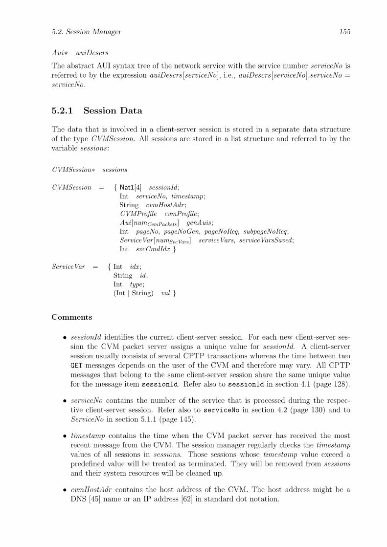
5.2. Session Manager 155
Aui∗ auiDescrs
The abstract AUI syntax tree of the network service with the service number serviceNo isreferred to by the expression auiDescrs [serviceNo], i.e., auiDescrs [serviceNo].serviceNo =serviceNo.
5.2.1 Session Data
The data that is involved in a client-server session is stored in a separate data structureof the type CVMSession. All sessions are stored in a list structure and referred to by thevariable sessions :
CVMSession∗ sessions
CVMSession = { Nat1[4] sessionId ;Int serviceNo, timestamp;String cvmHostAdr ;CVMProfile cvmProfile;Aui [numCvmPackets ] genAuis;Int pageNo, pageNoGen, pageNoReq, subpageNoReq ;ServiceVar [numSvcVars ] serviceVars, serviceVarsSaved ;Int svcCmdIdx }
ServiceVar = { Int idx ;String id ;Int type;(Int | String) val }
Comments
• sessionId identifies the current client-server session. For each new client-server ses-sion the CVM packet server assigns a unique value for sessionId. A client-serversession usually consists of several CPTP transactions whereas the time between twoGET messages depends on the user of the CVM and therefore may vary. All CPTPmessages that belong to the same client-server session share the same unique valuefor the message item sessionId. Refer also to sessionId in section 4.1 (page 128).
• serviceNo contains the number of the service that is processed during the respec-tive client-server session. Refer also to serviceNo in section 4.2 (page 130) and toServiceNo in section 5.1.1 (page 145).
• timestamp contains the time when the CVM packet server has received the mostrecent message from the CVM. The session manager regularly checks the timestampvalues of all sessions in sessions. Those sessions whose timestamp value exceed apredefined value will be treated as terminated. They will be removed from sessionsand their system resources will be cleaned up.
• cvmHostAdr contains the host address of the CVM. The host address might be aDNS [45] name or an IP address [62] in standard dot notation.
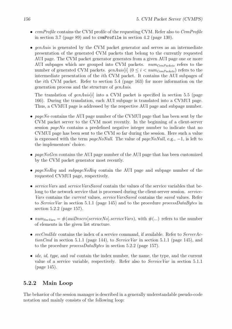
156 5. CVM Packet Server (CVMPS)
• cvmProfile contains the CVM profile of the requesting CVM. Refer also to CvmProfilein section 3.7 (page 89) and to cvmProfile in section 4.2 (page 130).
• genAuis is generated by the CVM packet generator and serves as an intermediatepresentation of the generated CVM packets that belong to the currently requestedAUI page. The CVM packet generator generates from a given AUI page one or moreAUI subpages which are grouped into CVM packets. numCvmPackets refers to thenumber of generated CVM packets. genAuis [i] (0 ≤ i < numCvmPackets) refers to theintermediate presentation of the ith CVM packet. It contains the AUI subpages ofthe ith CVM packet. Refer to section 5.4 (page 163) for more information on thegeneration process and the structure of genAuis.
The translation of genAuis [i] into a CVM packet is specified in section 5.5 (page166). During the translation, each AUI subpage is translated into a CVMUI page.Thus, a CVMUI page is addressed by the respective AUI page and subpage number.
• pageNo contains the AUI page number of the CVMUI page that has been sent by theCVM packet server to the CVM most recently. In the beginning of a client-serversession pageNo contains a predefined negative integer number to indicate that noCVMUI page has been sent to the CVM so far during the session. Here such a valueis expressed with the term pageNoNull. The value of pageNoNull, e.g., −1, is left tothe implementors’ choice.
• pageNoGen contains the AUI page number of the AUI page that has been customizedby the CVM packet generator most recently.
• pageNoReq and subpageNoReq contain the AUI page and subpage number of therequested CVMUI page, respectively.
• serviceVars and serviceVarsSaved contain the values of the service variables that be-long to the network service that is processed during the client-server session. service-Vars contains the current values, serviceVarsSaved contains the saved values. Referto ServiceVar in section 5.1.1 (page 145) and to the procedure processDataBytes insection 5.2.2 (page 157).
• numSvcVars = #(auiDescrs [serviceNo].serviceVars), with #(...) refers to the numberof elements in the given list structure.
• svcCmdIdx contains the index of a service command, if available. Refer to ServerAc-tionCmd in section 5.1.1 (page 144), to ServiceVar in section 5.1.1 (page 145), andto the procedure processDataBytes in section 5.2.2 (page 157).
• idx, id, type, and val contain the index number, the name, the type, and the currentvalue of a service variable, respectively. Refer also to ServiceVar in section 5.1.1(page 145).
5.2.2 Main Loop
The behavior of the session manager is described in a generally understandable pseudo-codenotation and mainly consists of the following loop:
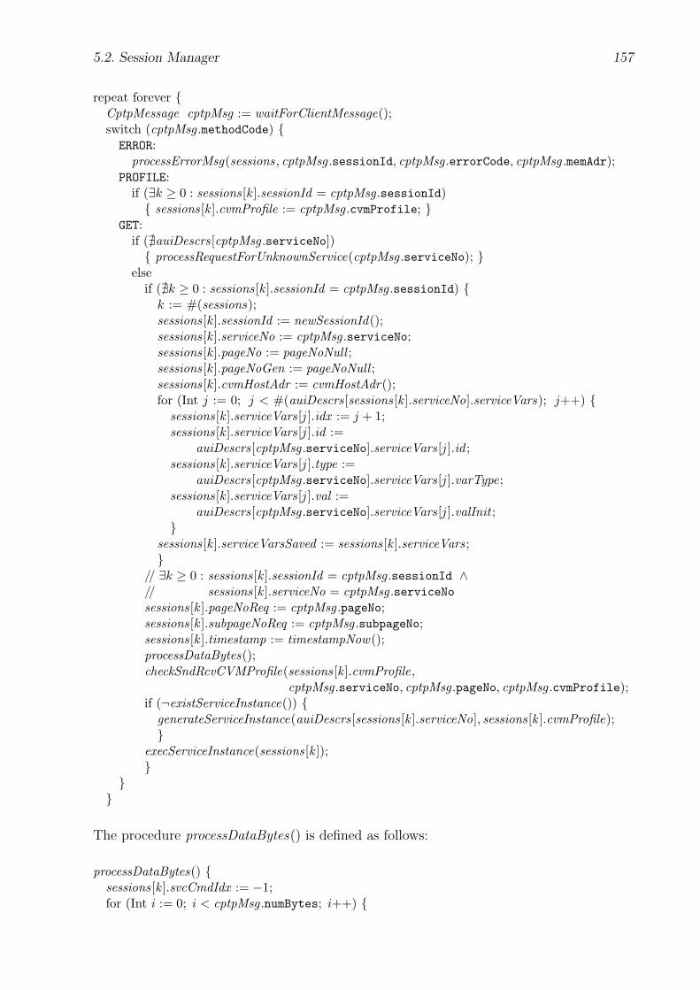
5.2. Session Manager 157
repeat forever {CptpMessage cptpMsg := waitForClientMessage();switch (cptpMsg .methodCode) {ERROR:
processErrorMsg(sessions, cptpMsg .sessionId, cptpMsg .errorCode, cptpMsg .memAdr);PROFILE:
if (∃k ≥ 0 : sessions[k ].sessionId = cptpMsg .sessionId){ sessions[k ].cvmProfile := cptpMsg .cvmProfile; }
GET:if (@auiDescrs[cptpMsg .serviceNo]){ processRequestForUnknownService(cptpMsg .serviceNo); }
elseif (@k ≥ 0 : sessions[k ].sessionId = cptpMsg .sessionId) {
k := #(sessions);sessions[k ].sessionId := newSessionId();sessions[k ].serviceNo := cptpMsg .serviceNo;sessions[k ].pageNo := pageNoNull ;sessions[k ].pageNoGen := pageNoNull ;sessions[k ].cvmHostAdr := cvmHostAdr();for (Int j := 0; j < #(auiDescrs[sessions[k ].serviceNo].serviceVars); j++) {
sessions[k ].serviceVars[j ].idx := j + 1;sessions[k ].serviceVars[j ].id :=
auiDescrs[cptpMsg .serviceNo].serviceVars[j ].id ;sessions[k ].serviceVars[j ].type :=
auiDescrs[cptpMsg .serviceNo].serviceVars[j ].varType;sessions[k ].serviceVars[j ].val :=
auiDescrs[cptpMsg .serviceNo].serviceVars[j ].valInit ;}
sessions[k ].serviceVarsSaved := sessions[k ].serviceVars;}
// ∃k ≥ 0 : sessions[k ].sessionId = cptpMsg .sessionId ∧// sessions[k ].serviceNo = cptpMsg .serviceNosessions[k ].pageNoReq := cptpMsg .pageNo;sessions[k ].subpageNoReq := cptpMsg .subpageNo;sessions[k ].timestamp := timestampNow();processDataBytes();checkSndRcvCVMProfile(sessions[k ].cvmProfile,
cptpMsg .serviceNo, cptpMsg .pageNo, cptpMsg .cvmProfile);if (¬existServiceInstance()) {
generateServiceInstance(auiDescrs[sessions[k ].serviceNo], sessions[k ].cvmProfile);}
execServiceInstance(sessions[k ]);}
}}
The procedure processDataBytes() is defined as follows:
processDataBytes() {sessions[k ].svcCmdIdx := −1;for (Int i := 0; i < cptpMsg .numBytes; i++) {
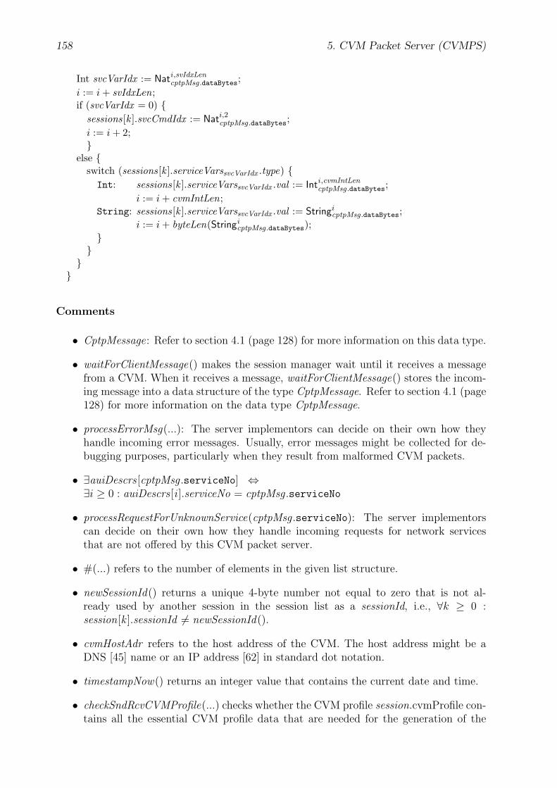
158 5. CVM Packet Server (CVMPS)
Int svcVarIdx := Nati ,svIdxLencptpMsg.dataBytes;
i := i + svIdxLen;if (svcVarIdx = 0) {
sessions[k ].svcCmdIdx := Nati,2cptpMsg.dataBytes;i := i + 2;}
else {switch (sessions[k ].serviceVarssvcVarIdx .type) {Int: sessions[k ].serviceVarssvcVarIdx .val := Inti ,cvmIntLen
cptpMsg.dataBytes;i := i + cvmIntLen;
String: sessions[k ].serviceVarssvcVarIdx .val := StringicptpMsg.dataBytes;
i := i + byteLen(StringicptpMsg.dataBytes);
}}}}
Comments
• CptpMessage: Refer to section 4.1 (page 128) for more information on this data type.
• waitForClientMessage() makes the session manager wait until it receives a messagefrom a CVM. When it receives a message, waitForClientMessage() stores the incom-ing message into a data structure of the type CptpMessage. Refer to section 4.1 (page128) for more information on the data type CptpMessage.
• processErrorMsg(...): The server implementors can decide on their own how theyhandle incoming error messages. Usually, error messages might be collected for de-bugging purposes, particularly when they result from malformed CVM packets.
• ∃auiDescrs [cptpMsg .serviceNo] ⇔∃i ≥ 0 : auiDescrs [i ].serviceNo = cptpMsg .serviceNo
• processRequestForUnknownService(cptpMsg .serviceNo): The server implementorscan decide on their own how they handle incoming requests for network servicesthat are not offered by this CVM packet server.
• #(...) refers to the number of elements in the given list structure.
• newSessionId() returns a unique 4-byte number not equal to zero that is not al-ready used by another session in the session list as a sessionId, i.e., ∀k ≥ 0 :session[k ].sessionId 6= newSessionId().
• cvmHostAdr refers to the host address of the CVM. The host address might be aDNS [45] name or an IP address [62] in standard dot notation.
• timestampNow() returns an integer value that contains the current date and time.
• checkSndRcvCVMProfile(...) checks whether the CVM profile session.cvmProfile con-tains all the essential CVM profile data that are needed for the generation of the

5.3. Service Generator 159
client-specific service instance and the CVM packets. If some profile items are miss-ing the session manager sends a CPTP message to the CVM to request the missingitems. Refer also to the CPTP protocol method PROFILE in section 4.2 (page 130).
• existServiceInstance() returns true, if the executable file of the client-specific serviceinstance has already been generated previously during this client-server session. Oth-erwise, it returns false. Here, the service instance is generated for each client-serversession only once and in the beginning of the session, i.e., when the first client requestwith the CPTP method GET is being processed by the session manager.
• generateServiceInstance(...) generates from a given AUI description and a given CVMprofile an executable file that represents the client-specific service instance. Refer tothe sections 5.3.1 (page 160) and 5.3 (page 159) for more information on the serviceinstance and its generation.
• execServiceInstance(...) executes the previously generated service instance file. Whethera separate and concurrent process is started for the service instance is left to the im-plementors’ choice.
• Nati ,svIdxLencptpMsg.dataBytes refers to the Nat<svIdxLen> number that starts in the byte array
cptpMsg.dataBytes at the index position i.
Inti ,cvmIntLencptpMsg.dataBytes refers to the Int<cvmIntLen> number that starts in the byte array
cptpMsg.dataBytes at the index position i.
StringicptpMsg.dataBytes refers to the CVM String that starts in the byte array cptpMsg.-
dataBytes at the index position i.
byteLen(StringicptpMsg.dataBytes) refers to the byte length of the whole given CVM String
structure.
Refer to section 3.1.1 (page 32) for more information on the CVM data types. Referto section 5.1.1 (page 145) for more information on service variables.
• session.serviceVarssvcVarIdx refers to the service variable that meets the following con-ditions:∃j ≥ 0 : (session.serviceVars [j] = session.serviceVarssvcVarIdx ∧
session.serviceVars [j ].idx = svcVarIdx )
• Note that the pseudo-code that decides which sessions in the session list are con-sidered as terminated — according to their timestamp values — and that regularlycleans up the session list is not shown here. This is left to the implementors’ choiceas well.
5.3 Service Generator
The service generator creates from the given Aui and CVMProfile data structures anexecutable file that represents the service instance. The Aui and the CVMProfile datatypes are specified in the sections 5.1.2 (page 147) and 3.7 (page 89), respectively. Theservice instance consists of a fixed and a generated part. The fixed part of the serviceinstance does not depend on the given AUI description and CVM profile and thereforeis the same in every client-server session. The generated part, however, does depend on
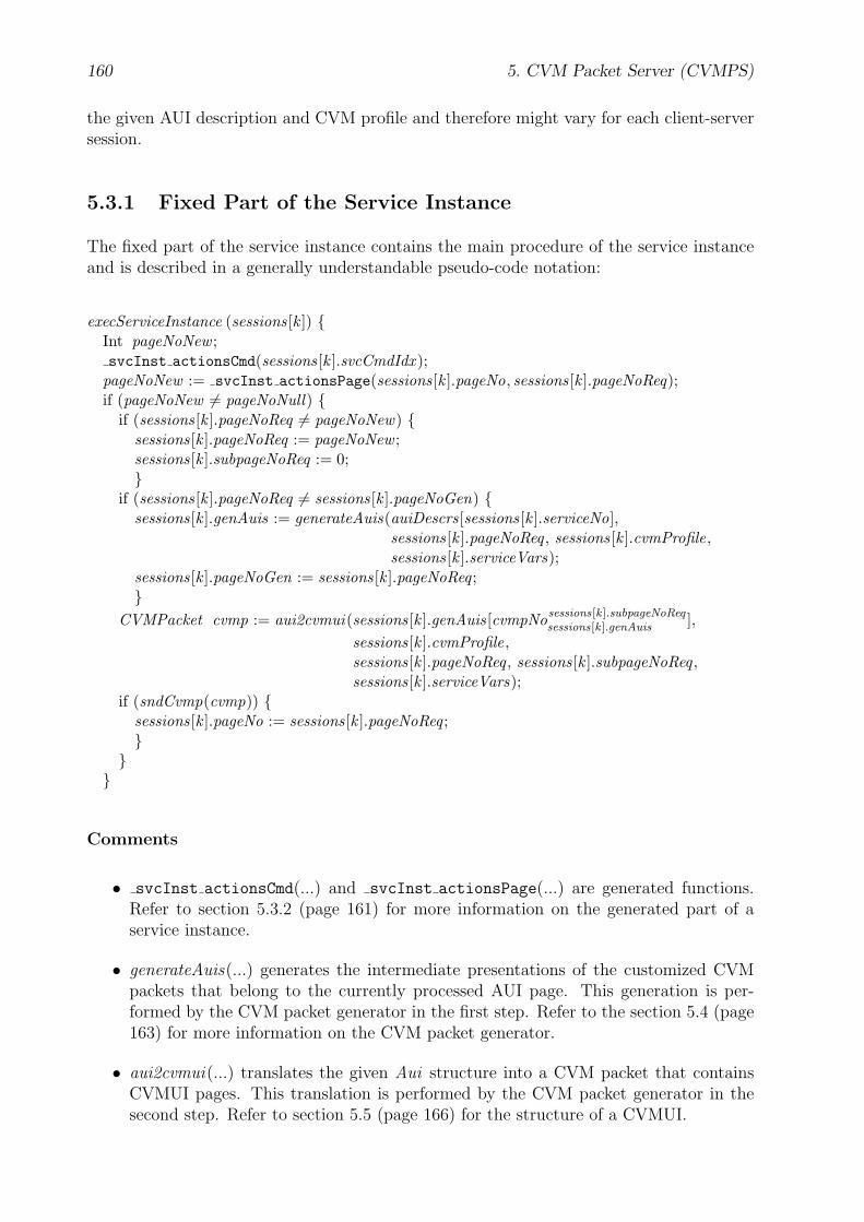
160 5. CVM Packet Server (CVMPS)
the given AUI description and CVM profile and therefore might vary for each client-serversession.
5.3.1 Fixed Part of the Service Instance
The fixed part of the service instance contains the main procedure of the service instanceand is described in a generally understandable pseudo-code notation:
execServiceInstance (sessions[k ]) {Int pageNoNew ;svcInst actionsCmd(sessions[k ].svcCmdIdx );
pageNoNew := svcInst actionsPage(sessions[k ].pageNo, sessions[k ].pageNoReq);if (pageNoNew 6= pageNoNull) {
if (sessions[k ].pageNoReq 6= pageNoNew) {sessions[k ].pageNoReq := pageNoNew ;sessions[k ].subpageNoReq := 0;}
if (sessions[k ].pageNoReq 6= sessions[k ].pageNoGen) {sessions[k ].genAuis := generateAuis(auiDescrs[sessions[k ].serviceNo],
sessions[k ].pageNoReq , sessions[k ].cvmProfile,sessions[k ].serviceVars);
sessions[k ].pageNoGen := sessions[k ].pageNoReq ;}
CVMPacket cvmp := aui2cvmui(sessions[k ].genAuis[cvmpNosessions[k ].subpageNoReqsessions[k ].genAuis ],
sessions[k ].cvmProfile,sessions[k ].pageNoReq , sessions[k ].subpageNoReq ,sessions[k ].serviceVars);
if (sndCvmp(cvmp)) {sessions[k ].pageNo := sessions[k ].pageNoReq ;}}}
Comments
• svcInst actionsCmd(...) and svcInst actionsPage(...) are generated functions.Refer to section 5.3.2 (page 161) for more information on the generated part of aservice instance.
• generateAuis(...) generates the intermediate presentations of the customized CVMpackets that belong to the currently processed AUI page. This generation is per-formed by the CVM packet generator in the first step. Refer to the section 5.4 (page163) for more information on the CVM packet generator.
• aui2cvmui(...) translates the given Aui structure into a CVM packet that containsCVMUI pages. This translation is performed by the CVM packet generator in thesecond step. Refer to section 5.5 (page 166) for the structure of a CVMUI.
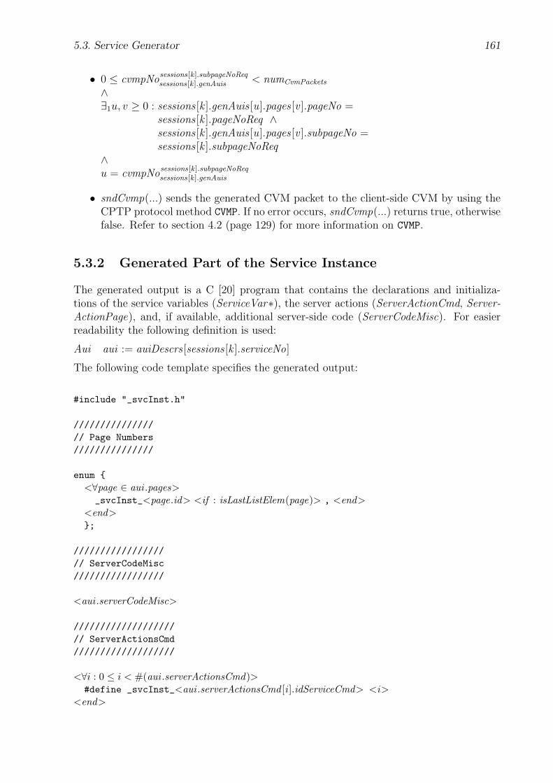
5.3. Service Generator 161
• 0 ≤ cvmpNosessions[k ].subpageNoReqsessions[k ].genAuis < numCvmPackets
∧∃1u, v ≥ 0 : sessions [k ].genAuis [u].pages [v ].pageNo =
sessions [k ].pageNoReq ∧sessions [k ].genAuis [u].pages [v ].subpageNo =sessions [k ].subpageNoReq
∧u = cvmpNo
sessions[k ].subpageNoReqsessions[k ].genAuis
• sndCvmp(...) sends the generated CVM packet to the client-side CVM by using theCPTP protocol method CVMP. If no error occurs, sndCvmp(...) returns true, otherwisefalse. Refer to section 4.2 (page 129) for more information on CVMP.
5.3.2 Generated Part of the Service Instance
The generated output is a C [20] program that contains the declarations and initializa-tions of the service variables (ServiceVar∗), the server actions (ServerActionCmd, Server-ActionPage), and, if available, additional server-side code (ServerCodeMisc). For easierreadability the following definition is used:
Aui aui := auiDescrs [sessions [k ].serviceNo]
The following code template specifies the generated output:
#include "_svcInst.h"
///////////////// Page Numbers///////////////
enum {<∀page ∈ aui .pages>_svcInst_<page.id> <if : isLastListElem(page)> , <end>
<end>};
/////////////////// ServerCodeMisc/////////////////
<aui .serverCodeMisc>
///////////////////// ServerActionsCmd///////////////////
<∀i : 0 ≤ i < #(aui .serverActionsCmd)>#define _svcInst_<aui .serverActionsCmd [i ].idServiceCmd> <i>
<end>

162 5. CVM Packet Server (CVMPS)
int _svcInst_actionsCmd (int svcCmdIdx){ dprint {<if : #(aui .serverActionsCmd) > 0>switch (svcCmdIdx)
{<∀serverActionCmd ∈ aui .serverActionsCmd>case _svcInst_<serverActionCmd .idServiceCmd>:{<serverActionsCmd .serverCode>}break;
<end>}
<end>}}
////////////////////// ServerActionsPage////////////////////
int _svcInst_actionsPage (int pageNow, int pageReq){ dprint {int pageNext = pageReq;<∀serverActionPage ∈ aui .serverActionsPage>
<if : isFirstListElem(serverActionPage)>if (
<else>else if (
<end><call : statePageId2boolExpr( pageNow, serverActionPage.idPageCurrent )>&&<call : statePageId2boolExpr( pageReq, serverActionPage.idPageNext )>)
{<serverActionPage.serverCode>}
<end>if (pageNext < _svcInst_<aui .pages[0].id> ||
pageNext > _svcInst_<lastListElem(aui .pages).id>){ pageNext = _svcInst_pageNoNull; }
return pageNext;}}
<fct : statePageId2boolExpr( String pageId , String statePageId )><if : statePageId = ””>
<pageId> == _svcInst_pageNoNull<elseif : statePageId = ”∗”>true
<elseif : statePageId = ”^”><pageId> < _svcInst_<aui .pages[0].id> ||<pageId> > _svcInst_<lastListElem(aui .pages).id>
<else>
5.4. CVM Packet Generator 163
<pageId> == _svcInst_<statePageId><end>
Comments
• isLastListElem(page) = true ⇔page is the last element in the list structure aui .pages
• isFirstListElem(serverActionPage) = true ⇔serverAction is the first element in the list structure aui .serverActions
• lastListElem(aui .pages) refers to the page that is the last element in the list structureaui .pages .
• _svcInst_pageNoNull equals to pageNoNull. Refer to section 5.2.1 (page 155) formore information on pageNoNull.
• Note that this (simple) code template does not depend on sessions [k ].cvmProfile,because its main purpose is only to demonstrate the proposed concepts. As alreadymentioned, the service providers can freely choose the complexity of their server-sidearchitectures.
5.4 CVM Packet Generator
The CVM packet generator generates from a given AUI page one or more AUI subpageswhich are grouped into CVM packets. Here the generation of the CVM packets takes placein two steps:
First a tree transformation is performed where the input tree represents the AUI descriptionof the currently processed network service and the output tree contains the intermediatepresentations of the customized CVM packets. Note that for the intermediate presentationof a generated CVM packet the data type Aui is used as well. In addition, an AUI subpageis represented by the data type Page. These data types are defined in section 5.1.2 (page147).
In the second step, the intermediate presentation of a customized CVM packet that containsthe requested AUI subpage is translated into a binary and executable CVM packet. Duringthe translation, each AUI subpage is translated into a CVMUI page. Thus, a CVMUI pageis addressed by the respective AUI page and subpage number. The structure of a CVMUIis specified in section 5.5 (page 166).
The tree transformation (generateAuis) in the first step is described as follows:
generateAuis : Aui × Nat × CVMProfile × ServiceVar∗ 7−→ Aui∗
generateAuis must meet particular conditions. For the specification of these conditions,first some definitions are made with respect to the previous sections:

164 5. CVM Packet Server (CVMPS)
Aui aui := auiDescrs [sessions [k ].serviceNo]
Nat numPages := #(aui .pages), with #(...) refers to the number of elements in the givenlist structure.
Without loss of generality: ∀q (0 ≤ q < numPages) : aui .pages [q ].pageNo = q ∧aui .pages [q ].subpageNo = 0
Nat pageNoReq := sessions [k ].pageNoReq
CVMProfile cvmProfile := sessions [k ].cvmProfile
ServiceVar serviceVars := sessions [k ].serviceVars
Aui [numCvmPackets ] genAuis := generateAuis(aui , pageNoReq , cvmProfile,serviceVars)
Then, genAuis must meet the following conditions:
(1) numCvmPackets > 0
(2) ∀p (0 ≤ p < numCvmPackets) :genAuis [p].serviceNo = aui .serviceNo ∧genAuis [p].serviceId = aui .serviceId ∧genAuis [p].serviceVars = aui .serviceVars ∧genAuis [p].serverLng = aui .serverLng ∧genAuis [p].serverActionsCmd = aui .serverActionsCmd ∧genAuis [p].serverActionsPage = aui .serverActionsPage ∧genAuis [p].serverCodeMisc = aui .serverCodeMisc ∧
(3) ∃numSubpages > 0 ∧ ∃numpSubpages > 0 (0 ≤ p < numCvmPackets) :
∀p (0 ≤ p < numCvmPackets) :∑p
numpSubpages = numSubpages ∧
#(genAuis [p].pages) = numPages + numpSubpages − 1
(4) ∀p (0 ≤ p < numCvmPackets) ∧ ∀q (0 ≤ q < numPages) :
q < pageNoReq ⇒ genAuis [p].pages [q ] = aui .pages [q ] ∧q > pageNoReq ⇒ genAuis [p].pages [q + nump
Subpages − 1] = aui .pages [q ]
(5) ∀p (0 ≤ p < numCvmPackets) ∧ ∀r (0 ≤ r < numpSubpages) :
genAuis [p].pages [pageNoReq + r ].id = aui .pages [pageNoReq ].id ∧genAuis [p].pages [pageNoReq + r ].pageNo = aui .pages [pageNoReq ].pageNo ∧0 ≤ genAuis [p].pages [pageNoReq + r ].subpageNo < numSubpages
(6) ∀j (0 ≤ j < numSubpages) :∃1p (0 ≤ p < numCvmPackets) ∧ ∃1q (0 ≤ q < #(genAuis [p].pages)) :
genAuis [p].pages [q ].pageNo = pageNoReq ∧genAuis [p].pages [q ].subpageNo = j
(7) ∀p (0 ≤ p < numCvmPackets) ∧ ∀r (0 ≤ r < numpSubpages) :
checkCvmPacket(aui2cvmui(genAuis [p], cvmProfile,genAuis [p].pages [pageNoReq + r ].pageNo,genAuis [p].pages [pageNoReq + r ].subpageNo,serviceVars),
cvmProfile) = true

5.4. CVM Packet Generator 165
Figure 5.3 (page 165) illustrates the structure of the output tree genAuis. In this figuresubpagep
r (0 ≤ r < numpSubpages) refers to genAuis [p].pages [pageNoReq + r ].
genAuis
genAuis[0] genAuis[p] genAuis[num - 1]CvmPackets
... ...
aui.serviceVars aui.serverActionsCmdpages
aui.pages[0] aui.pages[pageNoReq - 1] aui.pages[pageNoReq + 1]
... ... ...
aui.pages[num - 1]PagessubpageppnumSubpages
- 1
aui.serverActionsPage
subpagep0
Figure 5.3: generateAuis: Structure of the output tree genAuis
checkCvmPacket(...) verifies a customized CVM packet and returns true if the capabilitiesand restrictions of the requesting client device that are listed in the given CVM profileare completely respected by the CVM packet. For example, the CVM packet must neitherexceed the memory size of the CVM nor use font codes or library functions that are notsupported by the CVM. Refer to section 3.7 (page 89) for more information on the CVMprofile.
aui2cvmui(Aui genAui, CVMProfile cvmProfile, Nat pageNoReq, Nat subpageNoReq, Ser-viceVar∗ serviceVars) translates the given Aui tree genAui into a binary and executableCVM packet, called CVMUI. genAui represents the intermediate presentation of a cus-tomized CVM packet. Refer to section 5.5 (page 166) for more information on CVMUIs.
Note that the page items (pageItems) of the AUI subpages genAuis [p].pages [pageNoReq + r ](0 ≤ p < numCvmPackets , 0 ≤ r < nump
Subpages) are not further specified. By designing thecontents of the AUI subpages layout-related and ergonomic decisions have to be madewhich are left completely to the service providers. As far as the generated CVM packetconforms to the constraints listed in the CVM profile no further restrictions are dictated bythe proposed client-server architecture. As a proof of concept, a very simple customization

166 5. CVM Packet Server (CVMPS)
algorithm has been implemented and is demonstrated in the example in section D.2.2 (page295). The investigation of more complex customization algorithms is left for future work.
5.5 CVM User Interface (CVMUI)
A CVMUI is a CVMA program that contains a whole AUI page or only parts of it. Thissection describes the structure of a CVMUI. The proposed structure particularly takes intoaccount the GUI functionality, because a CVMUI mostly contains graphical user interfacecomponents. The abstraction level of such an operational user interface description appar-ently is quite low, because a CVMUI consists of CVM instructions. The CVM assemblertranslates a generated CVMUI into an executable CVM packet. Note that the CVMUIstructure that is presented in this thesis is only one exemplary structure of many otherpossible structures to demonstrate the proposed concepts.
In this section, the structure of the CVMA program for a generated Aui tree is presented.The following input values are used:
Aui genAuiCVMProfile cvmProfileInt pageNoReq , subpageNoReqServiceVar∗ serviceVars
genAui represents the generated Aui tree for a customized CVM packet. cvmProfile refersto the transmitted CVM profile. pageNoReq and subpageNoReq contain the AUI page andsubpage number of the requested CVMUI page, respectively. serviceVars contains thecurrent values of the service variables.
Refer to section A.4 (page 212) for a description of the used notation for the followingCVMA code templates. For easier readability, the additional definitions are used in thefollowing code templates:
Int numSvcVars := #(genAui .serviceVars),numPages := genAui .pages [#(genAui .pages)− 1].pageNo + 1
numPages refers to the number of AUI pages of the original Aui tree from which genAui isgenerated.
5.5.1 Global Structure
CVMA Code Template The CVMA code template for the global structure of a CVM-UI is as follows:
.<cvmProfile.cvmMode>Bit
.codeloadcr <pagepageNoReq,subpageNoReq .id>_<subpageNoReq>_mainjmp
//////////// Misc//////////
5.5. CVM User Interface (CVMUI) 167
.const_cil <cvmIntLen>_cvmScreenWidth <cvmProfile.cvmScreenWidth>_cvmScreenHeight <cvmProfile.cvmScreenHeight>
.dataString _hostAdrSrv "<hostAdrCvmPacketServer>"
//////////////////////// Page Numbers//////////////////////
.const_pageNo <pageNoReq>
<∀i : 0 ≤ i < pageNoReq>_<pagei ,0 .id> <i>
<end>
_<pagepageNoReq,subpageNoReq .id> <pageNoReq>
<∀i : pageNoReq < i < numPages>_<pagei ,0 .id> <i>
<end>
.dataInt _subpageNo
////////////////////////////// Service Commands////////////////////////////
.const<∀v : 0 ≤ v < #(genAui .serverActionsCmd)>
<genAui .serverActionsCmd [v ].idServiceCmd> <v><end>
//////////////////////////// Service Variables//////////////////////////
.const_svIdxLen <svIdxLen><∀v : 0 ≤ v < numSvcVars>_svIdx_<genAui .serviceVars[v ].id> <v + 1>
<end>
.dataInt _svBufIdx 0Bytes _svBuf
168 5. CVM Packet Server (CVMPS)
<∀guiCmpt ∈ guiCmptsSvIdxpageNoReq,j , j ≥ 0>_svIdxLen + <pagepageNoReq,j .id>_<j>_<guiCmpt .id>_svBufLen +
<end>_svIdxLen + 2
<if : Function _svBufIdx_reset() is referenced within this CVMUI>.fct _svBufIdx_reset(){// _svBufIdx := 0loadc_0store _svBufIdxreturn}
<end>
<if : Function _svBuf_svcCmd_write is referenced within this CVMUI>.fct _svBuf_svcCmd_write (Int svcCmdIdx){// _svBuf [_svBufIdx] := 0#svIdxLenloadc_0loadc _svBufload _svBufIdxastore<svIdxLen>// _svBufIdx += _svIdxLenload _svBufIdxloadc _svIdxLenaddstore _svBufIdx// _svBuf [_svBufIdx] := svcCmdIdx#2load svcCmdIdxloadc _svBufload _svBufIdxastore2// _svBufIdx += 2load _svBufIdxloadc 2addstore _svBufIdxreturn}
<end>
<if : Function _svBuf_write() is referenced within this CVMUI>.fct _svBuf_write(){fcall _svBufIdx_reset<∀j ≥ 0 : guiCmptsSvIdxpageNoReq,j 6= ∅>fcall <pagepageNoReq,j .id>_<j>_svBuf_write
<end>return}

5.5. CVM User Interface (CVMUI) 169
<end>
///////////////////////// CVMUI Pages///////////////////////
<∀j ≥ 0 : ∃pagepageNoReq,j ><import : CVMUI code for pagepageNoReq,j > // Refer to section 5.5.2 (page 170)
<end>
///////////////////// CVMUI Lib///////////////////
<import : CVMUI code for all referenced CVMUI Lib items>// Refer to section C (page 249)
Comments
• pagei ,j with i, j ≥ 0 refers to an AUI subpage that meets the following conditions:∃q ≥ 0 : (genAui .pages [q ] = pagei ,j ∧
genAui .pages [q ].pageNo = i ∧genAui .pages [q ].subpageNo = j )
• cvmIntLen depends on cvmProfile.cvmMode and refers to the byte length of an integernumber the client CVM operates on. Refer to section 3.1.2 (page 33) for moreinformation on cvmIntLen.
• cvmProfile.cvmScreenWidth ≡cvmProfile.profileItems [j].num, with j ≥ 0 and cvmProfile.profileItems [j].profile-ItemCode = cvmScreenWidth
The access to the other CVM profile item values is likewise.
• hostAdrCvmPacketServer refers to the IP [62] address or DNS [45] name of the CVMpacket server that serves the client.
• guiCmptsSvIdxpageNoReq,j :={guiCmpt ∈ pagepageNoReq,j .pageItems : svIdx ∈ guiCmpt .guiCmptItems}
• guiCmpt ∈ pagei ,j .pageItems ⇔∃k ≥ 0 : pagei ,j .pageItems [k ]GuiCmpt ∧ pagei ,j .pageItems [k] = guiCmpt ,with pagei ,j .pageItems [k ]GuiCmpt ≡The data type of pagei ,j .pageItems [k ] is GuiCmpt.
• svIdx ∈ guiCmpt .guiCmptItems ⇔∃l ≥ 0 : guiCmpt .guiCmptItems [l ]Attr ∧
guiCmpt .guiCmptItems [l].attrName = svIdx ,with guiCmpt .guiCmptItems [l ]Attr ≡The data type of guiCmpt .guiCmptItems [l ] is Attr.
• svIdxLen: Refer to ServiceVar in section 5.1.1 (page 146).

170 5. CVM Packet Server (CVMPS)
5.5.2 Page
CVMA Code Template The CVMA code template for the CVMUI page that repre-sents the AUI subpage pagepageNoReq,j (j ≥ 0) is as follows:
////////////////// Attributes////////////////
.const<pagepageNoReq,j .id>_<j>_x 0<pagepageNoReq,j .id>_<j>_y 0<pagepageNoReq,j .id>_<j>_w _cvmScreenWidth<pagepageNoReq,j .id>_<j>_h _cvmScreenHeight
<if : fg ∈ pagepageNoReq,j .pageItems><pagepageNoReq,j .id>_<j>_fgr <(attr(pagepageNoReq,j , fg)� 16) & 0xFF><pagepageNoReq,j .id>_<j>_fgg <(attr(pagepageNoReq,j , fg)� 8) & 0xFF><pagepageNoReq,j .id>_<j>_fgb <attr(pagepageNoReq,j , fg) & 0xFF>
<else><pagepageNoReq,j .id>_<j>_fgr 0<pagepageNoReq,j .id>_<j>_fgg 0<pagepageNoReq,j .id>_<j>_fgb 0
<end>
<if : bg ∈ pagepageNoReq,j .pageItems><pagepageNoReq,j .id>_<j>_bgr <(attr(pagepageNoReq,j , bg)� 16) & 0xFF><pagepageNoReq,j .id>_<j>_bgg <(attr(pagepageNoReq,j , bg)� 8) & 0xFF><pagepageNoReq,j .id>_<j>_bgb <attr(pagepageNoReq,j , bg) & 0xFF>
<else><pagepageNoReq,j .id>_<j>_bgr 255<pagepageNoReq,j .id>_<j>_bgg 255<pagepageNoReq,j .id>_<j>_bgb 255
<end>
<pagepageNoReq,j .id>_<j>_fc <if : fc ∈ pagepageNoReq,j .pageItems><attr(pagepageNoReq,j , fc)>
<else>fcFixedStandard
<end><pagepageNoReq,j .id>_<j>_fs <if : fs ∈ pagepageNoReq,j .pageItems>
<attr(pagepageNoReq,j , fs)><else>
13<end>
<pagepageNoReq,j .id>_<j>_img <if : img ∈ pagepageNoReq,j .pageItems><attr(pagepageNoReq,j , img)>
<else>""
<end>
5.5. CVM User Interface (CVMUI) 171
<pagepageNoReq,j .id>_<j>_imgStyle <if : imgStyle ∈ pagepageNoReq,j .pageItems><attr(pagepageNoReq,j , imgStyle)>
<else>0 // imgTile
<end>
.dataBytes <pagepageNoReq,j .id>_<j>_prp [ <pagepageNoReq,j .id>_<j>_et ]Int <pagepageNoReq,j .id>_<j>_bInit 0
//////////// Misc//////////
.code
.fct <pagepageNoReq,j .id>_<j>_main(){loadc <j>store _subpageNofcall <pagepageNoReq,j .id>_<j>_initfcall <pagepageNoReq,j .id>_<j>_drw<if : idxGuiCmptsInteractivepageNoReq,j 6= ∅>loadc <pagepageNoReq,j .id>_<j>_<guiCmpta0 .id>_prp pushloadc libGui<libGuiAbbr(guiCmpta0 .guiCmptType)><libGuiStyle>_drwFcs push
<else>loadc <pagepageNoReq,j .id>_<j>_prp pushloadc libMisc_emptyProc push
<end>fcall libGui_setFcsenableeventshalt}
.fct <pagepageNoReq,j .id>_<j>_init(){load <pagepageNoReq,j .id>_<j>_bInitloadc_0loadcr <pagepageNoReq,j .id>_<j>_init_<lblCntr1 >jne<∀guiCmpt ∈ pagepageNoReq,j .pageItems>
<if : guiCmpt .guiCmptType = Ixt>fcall <pagepageNoReq,j .id>_<j>_<guiCmpt .id>_init
<end><end>loadc_1store <pagepageNoReq,j >_<j>_bInit
<pagepageNoReq,j >_<j>_init_<lblCntr1 >:return}
.fct <pagepageNoReq,j .id>_<j>_drw()

172 5. CVM Packet Server (CVMPS)
{loadc <pagepageNoReq,j .id>_<j>_bgrloadc <pagepageNoReq,j .id>_<j>_bggloadc <pagepageNoReq,j .id>_<j>_bgbsetcolorloadc <pagepageNoReq,j .id>_<j>_xloadc <pagepageNoReq,j .id>_<j>_yloadc <pagepageNoReq,j .id>_<j>_wloadc <pagepageNoReq,j .id>_<j>_hrectfill<∀guiCmpt ∈ pagepageNoReq,j .pageItems>
<if : guiCmpt .guiCmptType = Txt ∨ guiCmpt .guiCmptType = Txp>fcall <pagepageNoReq,j .id>_<j>_<guiCmpt .id>_drw
<elseif : guiCmpt .guiCmptType = Btn ∨ guiCmpt .guiCmptType = Hlk ∨guiCmpt .guiCmptType = Ixt>
loadc <pagepageNoReq,j .id>_<j>_<guiCmpt .id>_prp pushfcall libGui<libGuiAbbr(guiCmpt .guiCmptType)><libGuiStyle>_drw
<end><end>return}
<if : ∃pagep,pageNoReq,j−1 ><pagepageNoReq,j .id>_<j>_prevPage:
<if : ∃pagepageNoReq,j−1 >loadc <j − 1>loadcr<pagepageNoReq,j−1 .id>_<j − 1>_mainpage
<else><if : ∃l ≥ 0 : guiCmptsSvIdxpageNoReq,l 6= ∅>fcall _svBuf_write
<else>fcall _svBufIdx_reset
<end>sendrcvpage _pageNo, <j − 1>
<end><end>
<if : ∃pagep,pageNoReq,j+1 ><pagepageNoReq,j .id>_<j>_nextPage:
<if : ∃pagepageNoReq,j+1 >loadc <j + 1>loadcr<pagepageNoReq,j+1 .id>_<j + 1>_mainpage
<else><if : ∃l ≥ 0 : guiCmptsSvIdxpageNoReq,l 6= ∅>fcall _svBuf_write
<else>fcall _svBufIdx_reset
<end>sendrcvpage _pageNo, <j + 1>

5.5. CVM User Interface (CVMUI) 173
<end><end>
//////////////////////////// Service Variables//////////////////////////
<if : guiCmptsSvIdxpageNoReq,j 6= ∅>.fct <pagepageNoReq,j .id>_<j>_svBuf_write(){load <pagepageNoReq,j .id>_<j>_bInitloadc_0loadcr <pagepageNoReq,j .id>_<j>_svBuf_write_<lblCntr1 >je<∀guiCmpt ∈ guiCmptsSvIdxpageNoReq,j >
fcall <pagepageNoReq,j .id>_<j>_<guiCmpt .id>_svBuf_write<end><pagepageNoReq,j .id>_<j>_svBuf_write_<lblCntr1 >:return}
<end>
////////////// Events////////////
.dataEventTable <pagepageNoReq,j .id>_<j>_et [
<if : idxGuiCmptsInteractivepageNoReq,j 6= ∅ ∨ ∃pagep,pageNoReq,j−1 ∨ ∃pagep,pageNoReq,j+1 ><if : cvmKeyCodeSet ∈ cvmProfile.profileItems>key_pressed, <pagepageNoReq,j .id>_<j>_kp<if : cvmMouseButtons ∈ cvmProfile.profileItems> , <end>
<end><if : cvmMouseButtons ∈ cvmProfile.profileItems>
mouse_pressed_left, <pagepageNoReq,j .id>_<j>_mpl<end>
<end>]
<if : idxGuiCmptsInteractivepageNoReq,j 6= ∅ ∨ ∃pagep,pageNoReq,j−1 ∨ ∃pagep,pageNoReq,j+1 ><if : cvmKeyCodeSet ∈ cvmProfile.profileItems>.code<pagepageNoReq,j .id>_<j>_kp:
<if : idxGuiCmptsInteractivepageNoReq,j 6= ∅>loadep1loadc XK_Tabloadcr <pagepageNoReq,j .id>_<j>_kp_tabje
<end><if : ∃pagep,pageNoReq,j−1 >loadep1
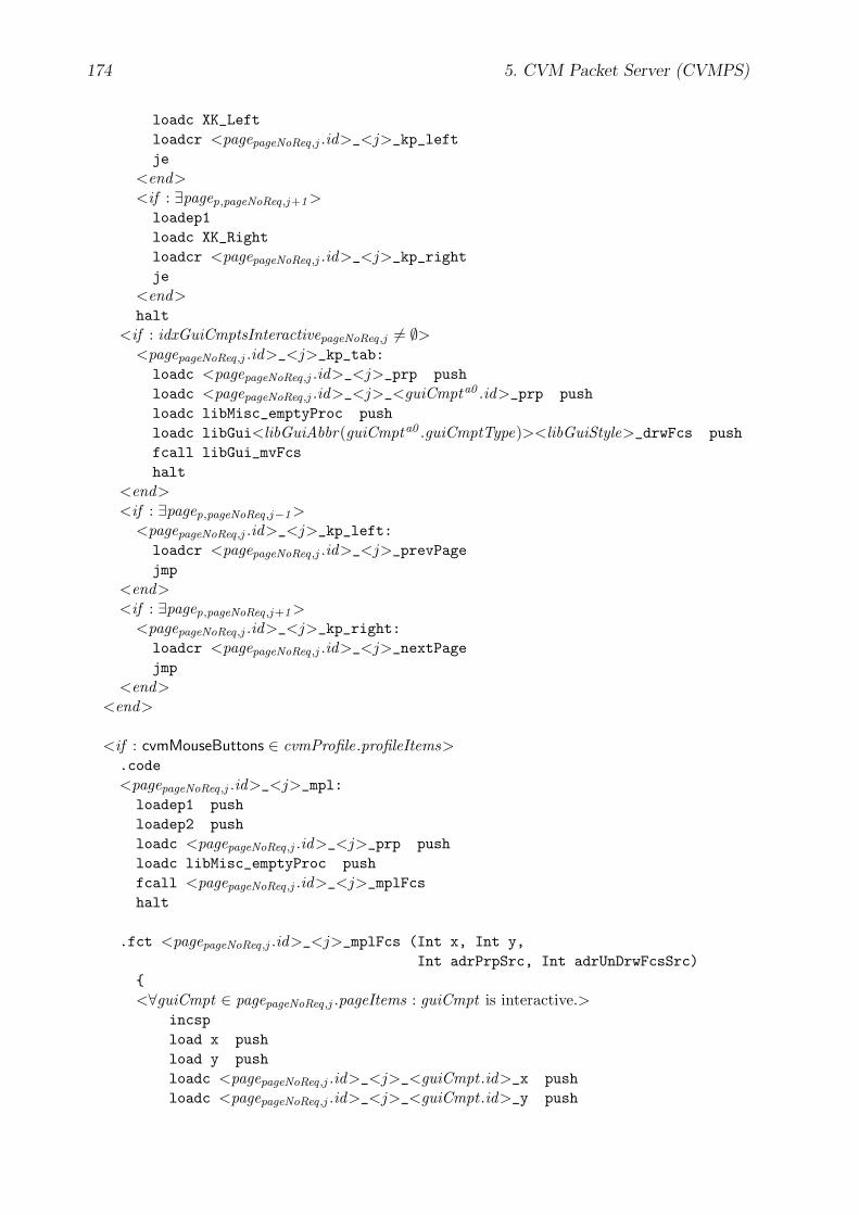
174 5. CVM Packet Server (CVMPS)
loadc XK_Leftloadcr <pagepageNoReq,j .id>_<j>_kp_leftje
<end><if : ∃pagep,pageNoReq,j+1 >loadep1loadc XK_Rightloadcr <pagepageNoReq,j .id>_<j>_kp_rightje
<end>halt
<if : idxGuiCmptsInteractivepageNoReq,j 6= ∅><pagepageNoReq,j .id>_<j>_kp_tab:loadc <pagepageNoReq,j .id>_<j>_prp pushloadc <pagepageNoReq,j .id>_<j>_<guiCmpta0 .id>_prp pushloadc libMisc_emptyProc pushloadc libGui<libGuiAbbr(guiCmpta0 .guiCmptType)><libGuiStyle>_drwFcs pushfcall libGui_mvFcshalt
<end><if : ∃pagep,pageNoReq,j−1 >
<pagepageNoReq,j .id>_<j>_kp_left:loadcr <pagepageNoReq,j .id>_<j>_prevPagejmp
<end><if : ∃pagep,pageNoReq,j+1 >
<pagepageNoReq,j .id>_<j>_kp_right:loadcr <pagepageNoReq,j .id>_<j>_nextPagejmp
<end><end>
<if : cvmMouseButtons ∈ cvmProfile.profileItems>.code<pagepageNoReq,j .id>_<j>_mpl:
loadep1 pushloadep2 pushloadc <pagepageNoReq,j .id>_<j>_prp pushloadc libMisc_emptyProc pushfcall <pagepageNoReq,j .id>_<j>_mplFcshalt
.fct <pagepageNoReq,j .id>_<j>_mplFcs (Int x, Int y,Int adrPrpSrc, Int adrUnDrwFcsSrc)
{<∀guiCmpt ∈ pagepageNoReq,j .pageItems : guiCmpt is interactive.>
incspload x pushload y pushloadc <pagepageNoReq,j .id>_<j>_<guiCmpt .id>_x pushloadc <pagepageNoReq,j .id>_<j>_<guiCmpt .id>_y push

5.5. CVM User Interface (CVMUI) 175
loadc <pagepageNoReq,j .id>_<j>_<guiCmpt .id>_w pushloadc <pagepageNoReq,j .id>_<j>_<guiCmpt .id>_h pushfcall libGui_rectInpop loadc_0 loadcr <pagepageNoReq,j .id>_<j>_mplFcs_<lblCntr2 > jeload adrPrpSrc pushloadc <pagepageNoReq,j .id>_<j>_<guiCmpt .id>_prp pushload adrUnDrwFcsSrc pushloadc libGui<libGuiAbbr(guiCmpt .guiCmptType)>
<libGuiStyle>_drwFcs pushfcall libGui_mvFcs<if : guiCmpt .guiCmptType = Btn>fcall <pagepageNoReq,j .id>_<j>_<guiCmpt .id>_evDwn
<elseif : guiCmpt .guiCmptType = Hlk>loadc <pagepageNoReq,j .id>_<j>_<guiCmpt .id>_prp pushfcall libGuiHlk_dwn
<end>return
<pagepageNoReq,j .id>_<j>_mplFcs_<lblCntr2 >:<end><if : ∃pagep,pageNoReq,j−1 >load xloadc _cvmScreenWidth loadc 2 divloadcr <pagepageNoReq,j .id>_<j>_prevPagejl<if : ∃pagep,pageNoReq,j+1 >
loadcr <pagepageNoReq,j .id>_<j>_nextPagejmp
<end><elseif : ∃pagep,pageNoReq,j+1 >loadc _cvmScreenWidth loadc 2 divload xloadcr <pagepageNoReq,j .id>_<j>_nextPagejl
<end>return}
<end><end>
//////////////////// Page Items//////////////////
<∀k ≥ 0 : ∃pageItemi ,j ,k><if : pageItemi ,j ,k GuiCmpt>
<import : CVMA code for pageItem> // Refer to sections 5.5.3 – 5.5.7 (pages 177 ff.)<elseif : pageItemi ,j ,k CvmAs>
<pageItem.cvmAs><end>

176 5. CVM Packet Server (CVMPS)
Comments
• attrName ∈ pagepageNoReq,j .pageItems ≡∃k ≥ 0 : pagepageNoReq,j .pageItems [k ]Attr ∧ pagepageNoReq,j .pageItems [k].attrName =attrName
• attr(pagepageNoReq,j , attrName) returns the value of the attribute with the name at-trName that is defined in pagepageNoReq,j . The data type of an attribute is Attrand is specified in section 5.1.2 (page 147). The value of an attribute is definedby its expression expr. Note that the value of a referenced service variable inexpr is determined by using the data structure sessions [k ].serviceVars instead ofsessions [k ].serviceVarsSaved . Refer to sections 5.1.1 (page 138) and 5.1.1 (page 145)for more information on attributes and service variables.
• idxGuiCmptsInteractivepageNoReq,j := {k ≥ 0 : pagepageNoReq,j .pageItems [k ]GuiCmpt ∧pagepageNoReq,j .pageItems [k ] is interactive}So far, interactive user interface components are of the type Btn, Hlk, or Ixt, i.e.,pagepageNoReq,j .pageItems [k ].guiCmptType ∈ {Btn, Hlk, Ixt}. Additional interactiveuser interface component types may be defined in the future.
• idxGuiCmptsInteractiveminpageNoReq,j ∈ idxGuiCmptsInteractivepageNoReq,j ∧
∀k ∈ idxGuiCmptsInteractivepageNoReq,j : idxGuiCmptsInteractiveminpageNoReq,j ≤ k
• guiCmpta0 := pagepageNoReq,j .pageItems [idxGuiCmptsInteractiveminpageNoReq,j ]
• libGuiAbbr(guiCmptType) returns the short name of the given user interface compo-nent type (guiCmptType):
libGuiAbbr(Btn) = Btn
libGuiAbbr(Ixt) = Ixt
libGuiAbbr(Txp) = Txp
libGuiAbbr(Txt) = Txt
This abbreviation is used in the CVMUI libraries. Refer to section C (page 249) formore information on the CVMUI libraries.
• libGuiStyle defines the appearance of the user interface components. So far, twostyles are defined in the CVMUI libraries: Smp and 3D.
• libGui..., libMisc..., e.g., libGuiBtnSmp drw, libGuiIxt3D drwFcs, libGuiHlk-
dwn, libGui setFcs, libGui rectIn, libMisc emptyProc, etc.These functions are defined in the CVMUI libraries. Refer to section C (pages 249ff.) for more information on the CVMUI libraries.
• lblCntrc (c ≥ 0) is a unique positive integer number that is used within label namesso that the labels are unique in the whole CVMA program.
• pagep,i ,j with p, i, j ≥ 0 refers to an Aui subpage that meets the following conditions:∃p, q ≥ 0 : (genAuis [p].pages [q ] = pagep,i ,j ∧
genAuis [p].pages [q ].pageNo = i ∧genAuis [p].pages [q ].subpageNo = j )
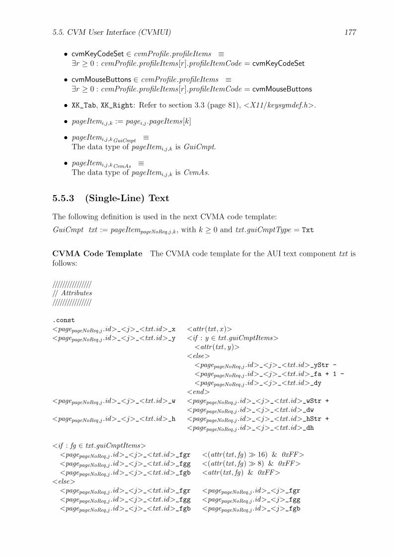
5.5. CVM User Interface (CVMUI) 177
• cvmKeyCodeSet ∈ cvmProfile.profileItems ≡∃r ≥ 0 : cvmProfile.profileItems [r].profileItemCode = cvmKeyCodeSet
• cvmMouseButtons ∈ cvmProfile.profileItems ≡∃r ≥ 0 : cvmProfile.profileItems [r].profileItemCode = cvmMouseButtons
• XK_Tab, XK_Right: Refer to section 3.3 (page 81), <X11/keysymdef.h>.
• pageItemi ,j ,k := pagei ,j .pageItems [k]
• pageItemi ,j ,k GuiCmpt ≡The data type of pageItemi ,j ,k is GuiCmpt.
• pageItemi ,j ,k CvmAs ≡The data type of pageItemi ,j ,k is CvmAs.
5.5.3 (Single-Line) Text
The following definition is used in the next CVMA code template:
GuiCmpt txt := pageItempageNoReq,j ,k , with k ≥ 0 and txt .guiCmptType = Txt
CVMA Code Template The CVMA code template for the AUI text component txt isfollows:
////////////////// Attributes////////////////
.const<pagepageNoReq,j .id>_<j>_<txt .id>_x <attr(txt , x )><pagepageNoReq,j .id>_<j>_<txt .id>_y <if : y ∈ txt .guiCmptItems>
<attr(txt , y)><else>
<pagepageNoReq,j .id>_<j>_<txt .id>_yStr -<pagepageNoReq,j .id>_<j>_<txt .id>_fa + 1 -<pagepageNoReq,j .id>_<j>_<txt .id>_dy
<end><pagepageNoReq,j .id>_<j>_<txt .id>_w <pagepageNoReq,j .id>_<j>_<txt .id>_wStr +
<pagepageNoReq,j .id>_<j>_<txt .id>_dw<pagepageNoReq,j .id>_<j>_<txt .id>_h <pagepageNoReq,j .id>_<j>_<txt .id>_hStr +
<pagepageNoReq,j .id>_<j>_<txt .id>_dh
<if : fg ∈ txt .guiCmptItems><pagepageNoReq,j .id>_<j>_<txt .id>_fgr <(attr(txt , fg)� 16) & 0xFF><pagepageNoReq,j .id>_<j>_<txt .id>_fgg <(attr(txt , fg)� 8) & 0xFF><pagepageNoReq,j .id>_<j>_<txt .id>_fgb <attr(txt , fg) & 0xFF>
<else><pagepageNoReq,j .id>_<j>_<txt .id>_fgr <pagepageNoReq,j .id>_<j>_fgr<pagepageNoReq,j .id>_<j>_<txt .id>_fgg <pagepageNoReq,j .id>_<j>_fgg<pagepageNoReq,j .id>_<j>_<txt .id>_fgb <pagepageNoReq,j .id>_<j>_fgb
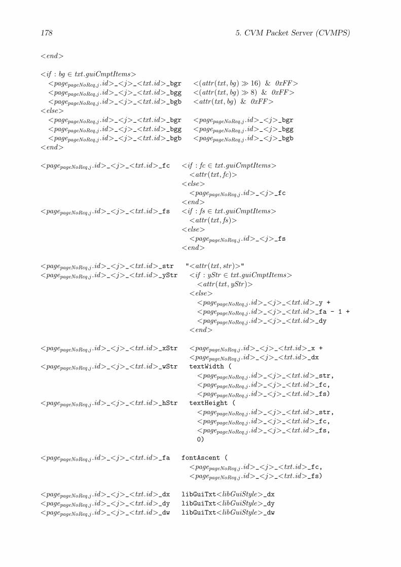
178 5. CVM Packet Server (CVMPS)
<end>
<if : bg ∈ txt .guiCmptItems><pagepageNoReq,j .id>_<j>_<txt .id>_bgr <(attr(txt , bg)� 16) & 0xFF><pagepageNoReq,j .id>_<j>_<txt .id>_bgg <(attr(txt , bg)� 8) & 0xFF><pagepageNoReq,j .id>_<j>_<txt .id>_bgb <attr(txt , bg) & 0xFF>
<else><pagepageNoReq,j .id>_<j>_<txt .id>_bgr <pagepageNoReq,j .id>_<j>_bgr<pagepageNoReq,j .id>_<j>_<txt .id>_bgg <pagepageNoReq,j .id>_<j>_bgg<pagepageNoReq,j .id>_<j>_<txt .id>_bgb <pagepageNoReq,j .id>_<j>_bgb
<end>
<pagepageNoReq,j .id>_<j>_<txt .id>_fc <if : fc ∈ txt .guiCmptItems><attr(txt , fc)>
<else><pagepageNoReq,j .id>_<j>_fc
<end><pagepageNoReq,j .id>_<j>_<txt .id>_fs <if : fs ∈ txt .guiCmptItems>
<attr(txt , fs)><else>
<pagepageNoReq,j .id>_<j>_fs<end>
<pagepageNoReq,j .id>_<j>_<txt .id>_str "<attr(txt , str)>"<pagepageNoReq,j .id>_<j>_<txt .id>_yStr <if : yStr ∈ txt .guiCmptItems>
<attr(txt , yStr)><else>
<pagepageNoReq,j .id>_<j>_<txt .id>_y +<pagepageNoReq,j .id>_<j>_<txt .id>_fa - 1 +<pagepageNoReq,j .id>_<j>_<txt .id>_dy
<end>
<pagepageNoReq,j .id>_<j>_<txt .id>_xStr <pagepageNoReq,j .id>_<j>_<txt .id>_x +<pagepageNoReq,j .id>_<j>_<txt .id>_dx
<pagepageNoReq,j .id>_<j>_<txt .id>_wStr textWidth (<pagepageNoReq,j .id>_<j>_<txt .id>_str,<pagepageNoReq,j .id>_<j>_<txt .id>_fc,<pagepageNoReq,j .id>_<j>_<txt .id>_fs)
<pagepageNoReq,j .id>_<j>_<txt .id>_hStr textHeight (<pagepageNoReq,j .id>_<j>_<txt .id>_str,<pagepageNoReq,j .id>_<j>_<txt .id>_fc,<pagepageNoReq,j .id>_<j>_<txt .id>_fs,0)
<pagepageNoReq,j .id>_<j>_<txt .id>_fa fontAscent (<pagepageNoReq,j .id>_<j>_<txt .id>_fc,<pagepageNoReq,j .id>_<j>_<txt .id>_fs)
<pagepageNoReq,j .id>_<j>_<txt .id>_dx libGuiTxt<libGuiStyle>_dx<pagepageNoReq,j .id>_<j>_<txt .id>_dy libGuiTxt<libGuiStyle>_dy<pagepageNoReq,j .id>_<j>_<txt .id>_dw libGuiTxt<libGuiStyle>_dw

5.5. CVM User Interface (CVMUI) 179
<pagepageNoReq,j .id>_<j>_<txt .id>_dh libGuiTxt<libGuiStyle>_dh
//////////// Misc//////////
.code
.fct <pagepageNoReq,j .id>_<j>_<txt .id>_drw(){loadc <pagepageNoReq,j .id>_<j>_<txt .id>_fgrloadc <pagepageNoReq,j .id>_<j>_<txt .id>_fggloadc <pagepageNoReq,j .id>_<j>_<txt .id>_fgbsetcolorloadc <pagepageNoReq,j .id>_<j>_<txt .id>_bgrloadc <pagepageNoReq,j .id>_<j>_<txt .id>_bggloadc <pagepageNoReq,j .id>_<j>_<txt .id>_bgbsetbgcolorloadc <pagepageNoReq,j .id>_<j>_<txt .id>_fcloadc <pagepageNoReq,j .id>_<j>_<txt .id>_fssetfontloadc <pagepageNoReq,j .id>_<j>_<txt .id>_xStrloadc <pagepageNoReq,j .id>_<j>_<txt .id>_yStrtextbg <pagepageNoReq,j .id>_<j>_<txt .id>_strreturn}
Comments
• attr(txt , attrName) returns the value of the attribute with the name attrName thatis defined in txt . The data type of the attribute is Attr and is defined in section 5.1.2(page 147). Refer to section 5.1.1 (page 138) for more information on attributes.
• fontAscent(), textWidth(), textHeight(): Refer to section B.4 (page 227) formore information on these CVMA builtin functions.
5.5.4 Text Paragraph
The following definition is used in the next CVMA code template:
GuiCmpt txp := pageItempageNoReq,j ,k , with k ≥ 0 and txp.guiCmptType = Txp
CVMA Code Template The CVMA code template for the AUI text component txp isfollows:
////////////////// Attributes////////////////
.const

180 5. CVM Packet Server (CVMPS)
<pagepageNoReq,j .id>_<j>_<txp.id>_x <attr(txp, x )><pagepageNoReq,j .id>_<j>_<txp.id>_y <if : y ∈ txp.guiCmptItems>
<attr(txp, y)><else>
<pagepageNoReq,j .id>_<j>_<txp.id>_yStr -<pagepageNoReq,j .id>_<j>_<txp.id>_fa + 1 -<pagepageNoReq,j .id>_<j>_<txp.id>_dy
<end><pagepageNoReq,j .id>_<j>_<txp.id>_w <attr(txp, w)><pagepageNoReq,j .id>_<j>_<txp.id>_h <pagepageNoReq,j .id>_<j>_<txp.id>_hStr +
<pagepageNoReq,j .id>_<j>_<txp.id>_dh
<if : fg ∈ txp.guiCmptItems><pagepageNoReq,j .id>_<j>_<txp.id>_fgr <(attr(txp, fg)� 16) & 0xFF><pagepageNoReq,j .id>_<j>_<txp.id>_fgg <(attr(txp, fg)� 8) & 0xFF><pagepageNoReq,j .id>_<j>_<txp.id>_fgb <attr(txp, fg) & 0xFF>
<else><pagepageNoReq,j .id>_<j>_<txp.id>_fgr <pagepageNoReq,j .id>_<j>_fgr<pagepageNoReq,j .id>_<j>_<txp.id>_fgg <pagepageNoReq,j .id>_<j>_fgg<pagepageNoReq,j .id>_<j>_<txp.id>_fgb <pagepageNoReq,j .id>_<j>_fgb
<end>
<if : bg ∈ txp.guiCmptItems><pagepageNoReq,j .id>_<j>_<txp.id>_bgr <(attr(txp, bg)� 16) & 0xFF><pagepageNoReq,j .id>_<j>_<txp.id>_bgg <(attr(txp, bg)� 8) & 0xFF><pagepageNoReq,j .id>_<j>_<txp.id>_bgb <attr(txp, bg) & 0xFF>
<else><pagepageNoReq,j .id>_<j>_<txp.id>_bgr <pagepageNoReq,j .id>_<j>_bgr<pagepageNoReq,j .id>_<j>_<txp.id>_bgg <pagepageNoReq,j .id>_<j>_bgg<pagepageNoReq,j .id>_<j>_<txp.id>_bgb <pagepageNoReq,j .id>_<j>_bgb
<end>
<pagepageNoReq,j .id>_<j>_<txp.id>_fc <if : fc ∈ txp.guiCmptItems><attr(txp, fc)>
<else><pagepageNoReq,j .id>_<j>_fc
<end><pagepageNoReq,j .id>_<j>_<txp.id>_fs <if : fs ∈ txp.guiCmptItems>
<attr(txp, fs)><else>
<pagepageNoReq,j .id>_<j>_fs<end>
<pagepageNoReq,j .id>_<j>_<txp.id>_strInit "<attr(txp, str)>"<pagepageNoReq,j .id>_<j>_<txp.id>_str textBreakLines (
<pagepageNoReq,j .id>_<j>_<txp.id>_strInit,<pagepageNoReq,j .id>_<j>_<txp.id>_fc,<pagepageNoReq,j .id>_<j>_<txp.id>_fs,<pagepageNoReq,j .id>_<j>_<txp.id>_w)
<pagepageNoReq,j .id>_<j>_<txp.id>_yStr <if : yStr ∈ txp.guiCmptItems><attr(txp, yStr)>

5.5. CVM User Interface (CVMUI) 181
<else><pagepageNoReq,j .id>_<j>_<txp.id>_y +<pagepageNoReq,j .id>_<j>_<txp.id>_fa - 1 +<pagepageNoReq,j .id>_<j>_<txp.id>_dy
<end>
<pagepageNoReq,j .id>_<j>_<txp.id>_xStr <pagepageNoReq,j .id>_<j>_<txp.id>_x +<pagepageNoReq,j .id>_<j>_<txp.id>_dx
<pagepageNoReq,j .id>_<j>_<txp.id>_wStr <pagepageNoReq,j .id>_<j>_<txp.id>_w -<pagepageNoReq,j .id>_<j>_<txp.id>_dw
<pagepageNoReq,j .id>_<j>_<txp.id>_hStr textHeight (<pagepageNoReq,j .id>_<j>_<txp.id>_str,<pagepageNoReq,j .id>_<j>_<txp.id>_fc,<pagepageNoReq,j .id>_<j>_<txp.id>_fs,0)
<pagepageNoReq,j .id>_<j>_<txp.id>_fa fontAscent (<pagepageNoReq,j .id>_<j>_<txp.id>_fc,<pagepageNoReq,j .id>_<j>_<txp.id>_fs)
<pagepageNoReq,j .id>_<j>_<txp.id>_dx libGuiTxp<libGuiStyle>_dx<pagepageNoReq,j .id>_<j>_<txp.id>_dy libGuiTxp<libGuiStyle>_dy<pagepageNoReq,j .id>_<j>_<txp.id>_dw libGuiTxp<libGuiStyle>_dw<pagepageNoReq,j .id>_<j>_<txp.id>_dh libGuiTxp<libGuiStyle>_dh
//////////// Misc//////////
.code
.fct <pagepageNoReq,j .id>_<j>_<txp.id>_drw(){loadc <pagepageNoReq,j .id>_<j>_<txp.id>_fgrloadc <pagepageNoReq,j .id>_<j>_<txp.id>_fggloadc <pagepageNoReq,j .id>_<j>_<txp.id>_fgbsetcolorloadc <pagepageNoReq,j .id>_<j>_<txp.id>_bgrloadc <pagepageNoReq,j .id>_<j>_<txp.id>_bggloadc <pagepageNoReq,j .id>_<j>_<txp.id>_bgbsetbgcolorloadc <pagepageNoReq,j .id>_<j>_<txp.id>_fcloadc <pagepageNoReq,j .id>_<j>_<txp.id>_fssetfontloadc <pagepageNoReq,j .id>_<j>_<txp.id>_xStrsetxtextlineloadc <pagepageNoReq,j .id>_<j>_<txp.id>_yStrtextpbg <pagepageNoReq,j .id>_<j>_<txp.id>_strreturn}
Comments
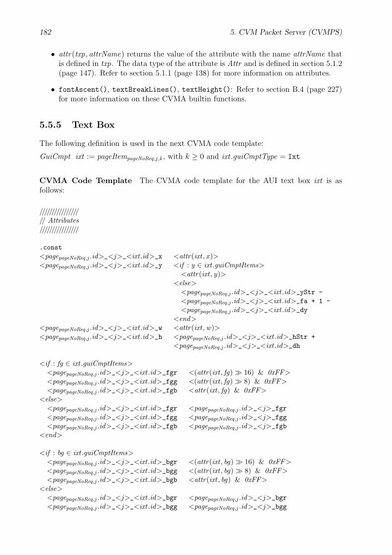
182 5. CVM Packet Server (CVMPS)
• attr(txp, attrName) returns the value of the attribute with the name attrName thatis defined in txp. The data type of the attribute is Attr and is defined in section 5.1.2(page 147). Refer to section 5.1.1 (page 138) for more information on attributes.
• fontAscent(), textBreakLines(), textHeight(): Refer to section B.4 (page 227)for more information on these CVMA builtin functions.
5.5.5 Text Box
The following definition is used in the next CVMA code template:
GuiCmpt ixt := pageItempageNoReq,j ,k , with k ≥ 0 and ixt .guiCmptType = Ixt
CVMA Code Template The CVMA code template for the AUI text box ixt is asfollows:
////////////////// Attributes////////////////
.const<pagepageNoReq,j .id>_<j>_<ixt .id>_x <attr(ixt , x )><pagepageNoReq,j .id>_<j>_<ixt .id>_y <if : y ∈ ixt .guiCmptItems>
<attr(ixt , y)><else>
<pagepageNoReq,j .id>_<j>_<ixt .id>_yStr -<pagepageNoReq,j .id>_<j>_<ixt .id>_fa + 1 -<pagepageNoReq,j .id>_<j>_<ixt .id>_dy
<end><pagepageNoReq,j .id>_<j>_<ixt .id>_w <attr(ixt , w)><pagepageNoReq,j .id>_<j>_<ixt .id>_h <pagepageNoReq,j .id>_<j>_<ixt .id>_hStr +
<pagepageNoReq,j .id>_<j>_<ixt .id>_dh
<if : fg ∈ ixt .guiCmptItems><pagepageNoReq,j .id>_<j>_<ixt .id>_fgr <(attr(ixt , fg)� 16) & 0xFF><pagepageNoReq,j .id>_<j>_<ixt .id>_fgg <(attr(ixt , fg)� 8) & 0xFF><pagepageNoReq,j .id>_<j>_<ixt .id>_fgb <attr(ixt , fg) & 0xFF>
<else><pagepageNoReq,j .id>_<j>_<ixt .id>_fgr <pagepageNoReq,j .id>_<j>_fgr<pagepageNoReq,j .id>_<j>_<ixt .id>_fgg <pagepageNoReq,j .id>_<j>_fgg<pagepageNoReq,j .id>_<j>_<ixt .id>_fgb <pagepageNoReq,j .id>_<j>_fgb
<end>
<if : bg ∈ ixt .guiCmptItems><pagepageNoReq,j .id>_<j>_<ixt .id>_bgr <(attr(ixt , bg)� 16) & 0xFF><pagepageNoReq,j .id>_<j>_<ixt .id>_bgg <(attr(ixt , bg)� 8) & 0xFF><pagepageNoReq,j .id>_<j>_<ixt .id>_bgb <attr(ixt , bg) & 0xFF>
<else><pagepageNoReq,j .id>_<j>_<ixt .id>_bgr <pagepageNoReq,j .id>_<j>_bgr<pagepageNoReq,j .id>_<j>_<ixt .id>_bgg <pagepageNoReq,j .id>_<j>_bgg

5.5. CVM User Interface (CVMUI) 183
<pagepageNoReq,j .id>_<j>_<ixt .id>_bgb <pagepageNoReq,j .id>_<j>_bgb<end>
<pagepageNoReq,j .id>_<j>_<ixt .id>_fc <if : fc ∈ ixt .guiCmptItems><attr(ixt , fc)>
<else><pagepageNoReq,j .id>_<j>_fc
<end><pagepageNoReq,j .id>_<j>_<ixt .id>_fs <if : fs ∈ ixt .guiCmptItems>
<attr(ixt , fs)><else>
<pagepageNoReq,j .id>_<j>_fs<end>
.dataBytes <pagepageNoReq,j .id>_<j>_<ixt .id>_str
<pagepageNoReq,j .id>_<j>_<ixt .id>_strLenMax + 3
.const<pagepageNoReq,j .id>_<j>_<ixt .id>_yStr <if : yStr ∈ ixt .guiCmptItems>
<attr(ixt , yStr)><else>
<pagepageNoReq,j .id>_<j>_<ixt .id>_y +<pagepageNoReq,j .id>_<j>_<ixt .id>_fa - 1 +<pagepageNoReq,j .id>_<j>_<ixt .id>_dy
<end><pagepageNoReq,j .id>_<j>_<ixt .id>_strLenMax <attr(ixt , strLenMax )>
<if : svIdx ∈ ixt .guiCmptItems><pagepageNoReq,j .id>_<j>_<ixt .id>_svIdx
_svIdx_<genAui .serviceVars[attr(ixt , svIdx )].id><pagepageNoReq,j .id>_<j>_<ixt .id>_svBufLen
<pagepageNoReq,j .id>_<j>_<ixt .id>_strLenMax + 3<end>
<pagepageNoReq,j .id>_<j>_<ixt .id>_xStr <pagepageNoReq,j .id>_<j>_<ixt .id>_x +<pagepageNoReq,j .id>_<j>_<ixt .id>_dx
<pagepageNoReq,j .id>_<j>_<ixt .id>_wStr <pagepageNoReq,j .id>_<j>_<ixt .id>_w -<pagepageNoReq,j .id>_<j>_<ixt .id>_dw
<pagepageNoReq,j .id>_<j>_<ixt .id>_hStr <pagepageNoReq,j .id>_<j>_<ixt .id>_fh<pagepageNoReq,j .id>_<j>_<ixt .id>_yaStr <pagepageNoReq,j .id>_<j>_<ixt .id>_y +
<pagepageNoReq,j .id>_<j>_<ixt .id>_dy
.dataString <pagepageNoReq,j .id>_<j>_<ixt .id>_strIni
"<strPraefix (attr(ixt , str), attr(ixt , strLenMax ))>"
.const<pagepageNoReq,j .id>_<j>_<ixt .id>_wChar textWidth (
" ",<pagepageNoReq,j .id>_<j>_<ixt .id>_fc,
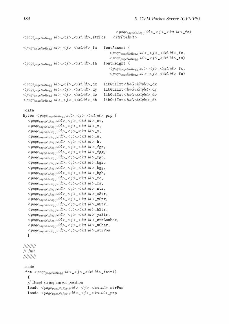
184 5. CVM Packet Server (CVMPS)
<pagepageNoReq,j .id>_<j>_<ixt .id>_fs)<pagepageNoReq,j .id>_<j>_<ixt .id>_strPos <strPosInit>
<pagepageNoReq,j .id>_<j>_<ixt .id>_fa fontAscent (<pagepageNoReq,j .id>_<j>_<ixt .id>_fc,<pagepageNoReq,j .id>_<j>_<ixt .id>_fs)
<pagepageNoReq,j .id>_<j>_<ixt .id>_fh fontHeight (<pagepageNoReq,j .id>_<j>_<ixt .id>_fc,<pagepageNoReq,j .id>_<j>_<ixt .id>_fs)
<pagepageNoReq,j .id>_<j>_<ixt .id>_dx libGuiIxt<libGuiStyle>_dx<pagepageNoReq,j .id>_<j>_<ixt .id>_dy libGuiIxt<libGuiStyle>_dy<pagepageNoReq,j .id>_<j>_<ixt .id>_dw libGuiIxt<libGuiStyle>_dw<pagepageNoReq,j .id>_<j>_<ixt .id>_dh libGuiIxt<libGuiStyle>_dh
.dataBytes <pagepageNoReq,j .id>_<j>_<ixt .id>_prp [
<pagepageNoReq,j .id>_<j>_<ixt .id>_et,<pagepageNoReq,j .id>_<j>_<ixt .id>_x,<pagepageNoReq,j .id>_<j>_<ixt .id>_y,<pagepageNoReq,j .id>_<j>_<ixt .id>_w,<pagepageNoReq,j .id>_<j>_<ixt .id>_h,<pagepageNoReq,j .id>_<j>_<ixt .id>_fgr,<pagepageNoReq,j .id>_<j>_<ixt .id>_fgg,<pagepageNoReq,j .id>_<j>_<ixt .id>_fgb,<pagepageNoReq,j .id>_<j>_<ixt .id>_bgr,<pagepageNoReq,j .id>_<j>_<ixt .id>_bgg,<pagepageNoReq,j .id>_<j>_<ixt .id>_bgb,<pagepageNoReq,j .id>_<j>_<ixt .id>_fc,<pagepageNoReq,j .id>_<j>_<ixt .id>_fs,<pagepageNoReq,j .id>_<j>_<ixt .id>_str,<pagepageNoReq,j .id>_<j>_<ixt .id>_xStr,<pagepageNoReq,j .id>_<j>_<ixt .id>_yStr,<pagepageNoReq,j .id>_<j>_<ixt .id>_wStr,<pagepageNoReq,j .id>_<j>_<ixt .id>_hStr,<pagepageNoReq,j .id>_<j>_<ixt .id>_yaStr,<pagepageNoReq,j .id>_<j>_<ixt .id>_strLenMax,<pagepageNoReq,j .id>_<j>_<ixt .id>_wChar,<pagepageNoReq,j .id>_<j>_<ixt .id>_strPos]
/////////// Init/////////
.code
.fct <pagepageNoReq,j .id>_<j>_<ixt .id>_init(){// Reset string cursor positionloadc <pagepageNoReq,j .id>_<j>_<ixt .id>_strPosloadc <pagepageNoReq,j .id>_<j>_<ixt .id>_prp
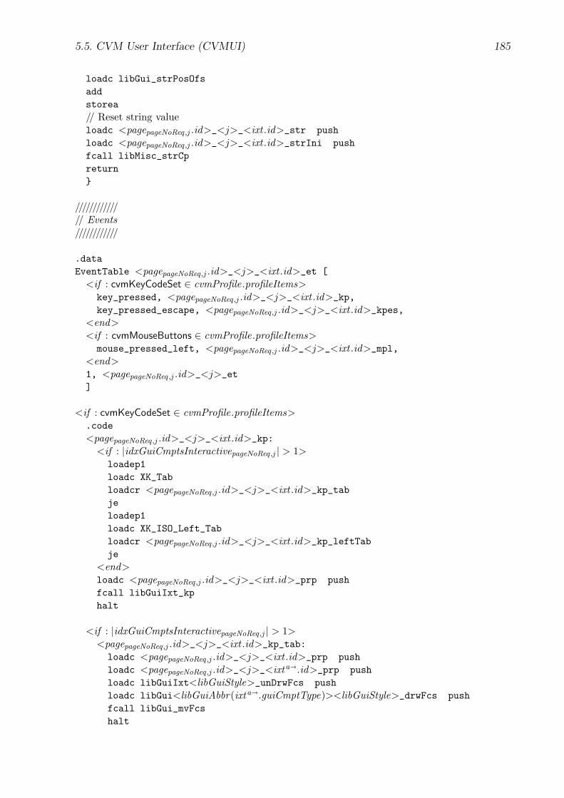
5.5. CVM User Interface (CVMUI) 185
loadc libGui_strPosOfsaddstorea// Reset string valueloadc <pagepageNoReq,j .id>_<j>_<ixt .id>_str pushloadc <pagepageNoReq,j .id>_<j>_<ixt .id>_strIni pushfcall libMisc_strCpreturn}
////////////// Events////////////
.dataEventTable <pagepageNoReq,j .id>_<j>_<ixt .id>_et [
<if : cvmKeyCodeSet ∈ cvmProfile.profileItems>key_pressed, <pagepageNoReq,j .id>_<j>_<ixt .id>_kp,key_pressed_escape, <pagepageNoReq,j .id>_<j>_<ixt .id>_kpes,
<end><if : cvmMouseButtons ∈ cvmProfile.profileItems>mouse_pressed_left, <pagepageNoReq,j .id>_<j>_<ixt .id>_mpl,
<end>1, <pagepageNoReq,j .id>_<j>_et]
<if : cvmKeyCodeSet ∈ cvmProfile.profileItems>.code<pagepageNoReq,j .id>_<j>_<ixt .id>_kp:
<if : |idxGuiCmptsInteractivepageNoReq,j | > 1>loadep1loadc XK_Tabloadcr <pagepageNoReq,j .id>_<j>_<ixt .id>_kp_tabjeloadep1loadc XK_ISO_Left_Tabloadcr <pagepageNoReq,j .id>_<j>_<ixt .id>_kp_leftTabje
<end>loadc <pagepageNoReq,j .id>_<j>_<ixt .id>_prp pushfcall libGuiIxt_kphalt
<if : |idxGuiCmptsInteractivepageNoReq,j | > 1><pagepageNoReq,j .id>_<j>_<ixt .id>_kp_tab:loadc <pagepageNoReq,j .id>_<j>_<ixt .id>_prp pushloadc <pagepageNoReq,j .id>_<j>_<ixta�.id>_prp pushloadc libGuiIxt<libGuiStyle>_unDrwFcs pushloadc libGui<libGuiAbbr(ixta�.guiCmptType)><libGuiStyle>_drwFcs pushfcall libGui_mvFcshalt
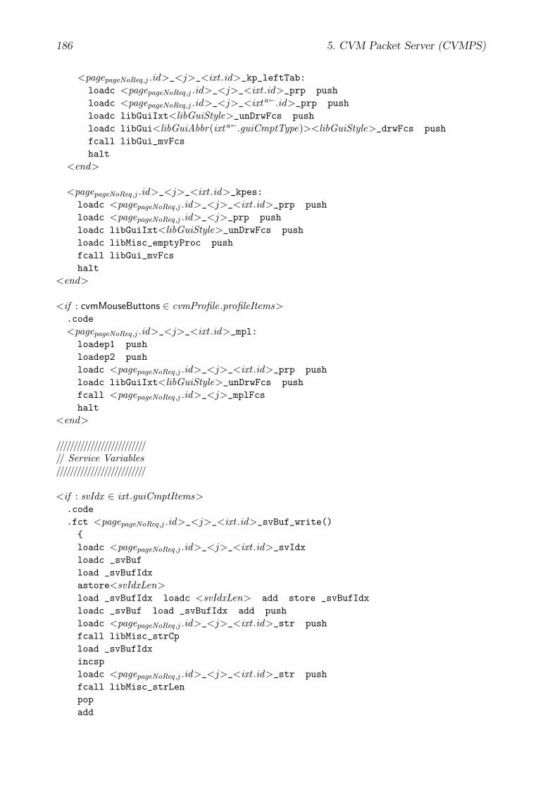
186 5. CVM Packet Server (CVMPS)
<pagepageNoReq,j .id>_<j>_<ixt .id>_kp_leftTab:loadc <pagepageNoReq,j .id>_<j>_<ixt .id>_prp pushloadc <pagepageNoReq,j .id>_<j>_<ixta�.id>_prp pushloadc libGuiIxt<libGuiStyle>_unDrwFcs pushloadc libGui<libGuiAbbr(ixta�.guiCmptType)><libGuiStyle>_drwFcs pushfcall libGui_mvFcshalt
<end>
<pagepageNoReq,j .id>_<j>_<ixt .id>_kpes:loadc <pagepageNoReq,j .id>_<j>_<ixt .id>_prp pushloadc <pagepageNoReq,j .id>_<j>_prp pushloadc libGuiIxt<libGuiStyle>_unDrwFcs pushloadc libMisc_emptyProc pushfcall libGui_mvFcshalt
<end>
<if : cvmMouseButtons ∈ cvmProfile.profileItems>.code<pagepageNoReq,j .id>_<j>_<ixt .id>_mpl:loadep1 pushloadep2 pushloadc <pagepageNoReq,j .id>_<j>_<ixt .id>_prp pushloadc libGuiIxt<libGuiStyle>_unDrwFcs pushfcall <pagepageNoReq,j .id>_<j>_mplFcshalt
<end>
//////////////////////////// Service Variables//////////////////////////
<if : svIdx ∈ ixt .guiCmptItems>.code.fct <pagepageNoReq,j .id>_<j>_<ixt .id>_svBuf_write(){loadc <pagepageNoReq,j .id>_<j>_<ixt .id>_svIdxloadc _svBufload _svBufIdxastore<svIdxLen>load _svBufIdx loadc <svIdxLen> add store _svBufIdxloadc _svBuf load _svBufIdx add pushloadc <pagepageNoReq,j .id>_<j>_<ixt .id>_str pushfcall libMisc_strCpload _svBufIdxincsploadc <pagepageNoReq,j .id>_<j>_<ixt .id>_str pushfcall libMisc_strLenpopadd
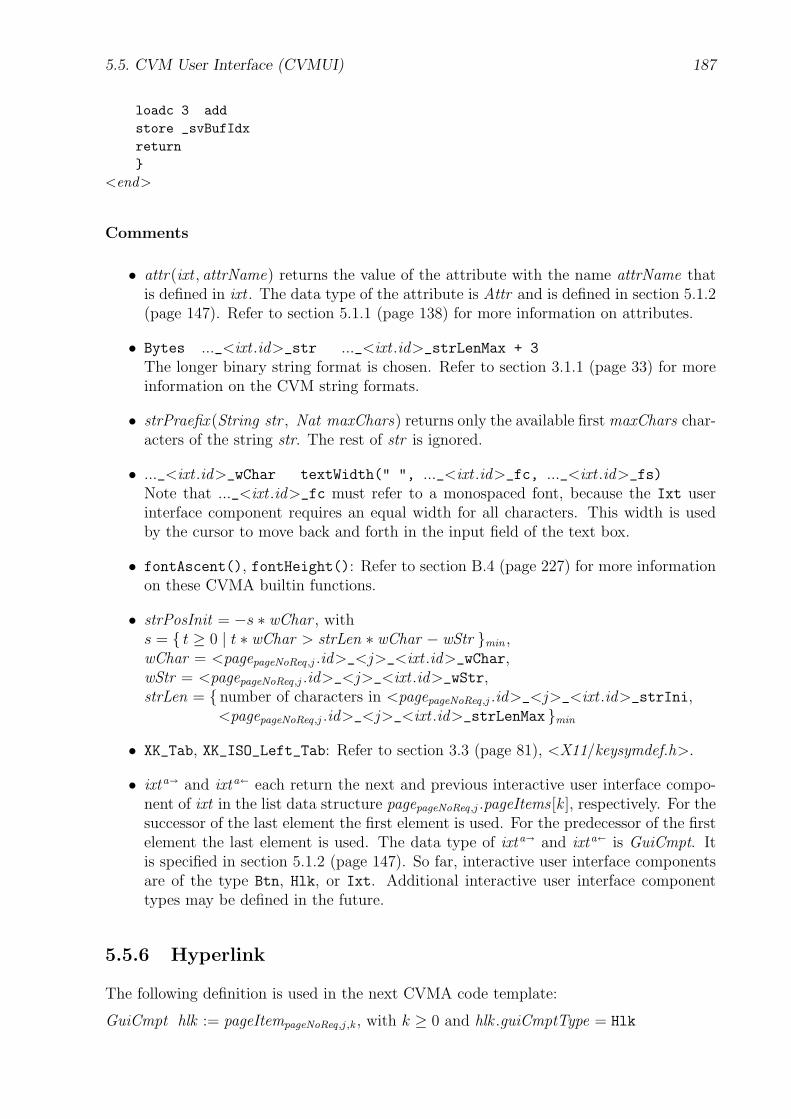
5.5. CVM User Interface (CVMUI) 187
loadc 3 addstore _svBufIdxreturn}
<end>
Comments
• attr(ixt , attrName) returns the value of the attribute with the name attrName thatis defined in ixt . The data type of the attribute is Attr and is defined in section 5.1.2(page 147). Refer to section 5.1.1 (page 138) for more information on attributes.
• Bytes ..._<ixt .id>_str ..._<ixt .id>_strLenMax + 3
The longer binary string format is chosen. Refer to section 3.1.1 (page 33) for moreinformation on the CVM string formats.
• strPraefix (String str , Nat maxChars) returns only the available first maxChars char-acters of the string str. The rest of str is ignored.
• ..._<ixt .id>_wChar textWidth(" ", ..._<ixt .id>_fc, ..._<ixt .id>_fs)Note that ..._<ixt .id>_fc must refer to a monospaced font, because the Ixt userinterface component requires an equal width for all characters. This width is usedby the cursor to move back and forth in the input field of the text box.
• fontAscent(), fontHeight(): Refer to section B.4 (page 227) for more informationon these CVMA builtin functions.
• strPosInit = −s ∗ wChar , withs = { t ≥ 0 | t ∗ wChar > strLen ∗ wChar − wStr }min ,wChar = <pagepageNoReq,j .id>_<j>_<ixt .id>_wChar,wStr = <pagepageNoReq,j .id>_<j>_<ixt .id>_wStr,strLen = { number of characters in <pagepageNoReq,j .id>_<j>_<ixt .id>_strIni,
<pagepageNoReq,j .id>_<j>_<ixt .id>_strLenMax }min
• XK_Tab, XK_ISO_Left_Tab: Refer to section 3.3 (page 81), <X11/keysymdef.h>.
• ixta� and ixta� each return the next and previous interactive user interface compo-nent of ixt in the list data structure pagepageNoReq,j .pageItems [k ], respectively. For thesuccessor of the last element the first element is used. For the predecessor of the firstelement the last element is used. The data type of ixta� and ixta� is GuiCmpt. Itis specified in section 5.1.2 (page 147). So far, interactive user interface componentsare of the type Btn, Hlk, or Ixt. Additional interactive user interface componenttypes may be defined in the future.
5.5.6 Hyperlink
The following definition is used in the next CVMA code template:
GuiCmpt hlk := pageItempageNoReq,j ,k , with k ≥ 0 and hlk .guiCmptType = Hlk
188 5. CVM Packet Server (CVMPS)
CVMA Code Template The CVMA code template for the AUI hyperlink hlk is asfollows:
////////////////// Attributes////////////////
.const<pagepageNoReq,j .id>_<j>_<hlk .id>_x <attr(hlk , x )><pagepageNoReq,j .id>_<j>_<hlk .id>_y <if : y ∈ hlk .guiCmptItems>
<attr(hlk , y)><else>
<pagepageNoReq,j .id>_<j>_<hlk .id>_yStr -<pagepageNoReq,j .id>_<j>_<hlk .id>_fa + 1 -<pagepageNoReq,j .id>_<j>_<hlk .id>_dy
<end><pagepageNoReq,j .id>_<j>_<hlk .id>_w <if : str ∈ hlk .guiCmptItems>
<pagepageNoReq,j .id>_<j>_<hlk .id>_wStr +<pagepageNoReq,j .id>_<j>_<hlk .id>_dw
<else><attr(hlk , w)>
<end><pagepageNoReq,j .id>_<j>_<hlk .id>_h <if : str ∈ hlk .guiCmptItems>
<pagepageNoReq,j .id>_<j>_<hlk .id>_hStr +<pagepageNoReq,j .id>_<j>_<hlk .id>_dh
<else><attr(hlk , h)>
<end>
<if : fg ∈ hlk .guiCmptItems><pagepageNoReq,j .id>_<j>_<hlk .id>_fgr <(attr(hlk , fg)� 16) & 0xFF><pagepageNoReq,j .id>_<j>_<hlk .id>_fgg <(attr(hlk , fg)� 8) & 0xFF><pagepageNoReq,j .id>_<j>_<hlk .id>_fgb <attr(hlk , fg) & 0xFF>
<else><pagepageNoReq,j .id>_<j>_<hlk .id>_fgr <pagepageNoReq,j .id>_<j>_fgr<pagepageNoReq,j .id>_<j>_<hlk .id>_fgg <pagepageNoReq,j .id>_<j>_fgg<pagepageNoReq,j .id>_<j>_<hlk .id>_fgb <pagepageNoReq,j .id>_<j>_fgb
<end>
<if : bg ∈ hlk .guiCmptItems><pagepageNoReq,j .id>_<j>_<hlk .id>_bgr <(attr(hlk , bg)� 16) & 0xFF><pagepageNoReq,j .id>_<j>_<hlk .id>_bgg <(attr(hlk , bg)� 8) & 0xFF><pagepageNoReq,j .id>_<j>_<hlk .id>_bgb <attr(hlk , bg) & 0xFF>
<else><pagepageNoReq,j .id>_<j>_<hlk .id>_bgr <pagepageNoReq,j .id>_<j>_bgr<pagepageNoReq,j .id>_<j>_<hlk .id>_bgg <pagepageNoReq,j .id>_<j>_bgg<pagepageNoReq,j .id>_<j>_<hlk .id>_bgb <pagepageNoReq,j .id>_<j>_bgb
<end>
<pagepageNoReq,j .id>_<j>_<hlk .id>_fc <if : fc ∈ hlk .guiCmptItems><attr(hlk , fc)>
5.5. CVM User Interface (CVMUI) 189
<else><pagepageNoReq,j .id>_<j>_fc
<end><pagepageNoReq,j .id>_<j>_<hlk .id>_fs <if : fs ∈ hlk .guiCmptItems>
<attr(hlk , fs)><else>
<pagepageNoReq,j .id>_<j>_fs<end>
<pagepageNoReq,j .id>_<j>_<hlk .id>_str <if : str ∈ hlk .guiCmptItems>"<attr(hlk , img)>"
<else>""
<end><pagepageNoReq,j .id>_<j>_<hlk .id>_yStr <if : yStr ∈ hlk .guiCmptItems>
<attr(hlk , yStr)><else>
<pagepageNoReq,j .id>_<j>_<hlk .id>_y +<pagepageNoReq,j .id>_<j>_<hlk .id>_fa - 1 +<pagepageNoReq,j .id>_<j>_<hlk .id>_dy
<end>
<pagepageNoReq,j .id>_<j>_<hlk .id>_hostAdr "<attr(hlk , hostAdr)>"<pagepageNoReq,j .id>_<j>_<hlk .id>_serviceNo <attr(hlk , serviceNo)>
<pagepageNoReq,j .id>_<j>_<hlk .id>_xStr <pagepageNoReq,j .id>_<j>_<hlk .id>_x +<pagepageNoReq,j .id>_<j>_<hlk .id>_dx
<pagepageNoReq,j .id>_<j>_<hlk .id>_wStr <if : str ∈ hlk .guiCmptItems>textWidth (
<pagepageNoReq,j .id>_<j>_<hlk .id>_str,<pagepageNoReq,j .id>_<j>_<hlk .id>_fc,<pagepageNoReq,j .id>_<j>_<hlk .id>_fs)
<else><pagepageNoReq,j .id>_<j>_<hlk .id>_w -<pagepageNoReq,j .id>_<j>_<hlk .id>_dw
<end><pagepageNoReq,j .id>_<j>_<hlk .id>_hStr <if : str ∈ hlk .guiCmptItems>
textHeight (<pagepageNoReq,j .id>_<j>_<hlk .id>_str,<pagepageNoReq,j .id>_<j>_<hlk .id>_fc,<pagepageNoReq,j .id>_<j>_<hlk .id>_fs,0)
<else><pagepageNoReq,j .id>_<j>_<hlk .id>_fh
<end>
<pagepageNoReq,j .id>_<j>_<hlk .id>_fa fontAscent (<pagepageNoReq,j .id>_<j>_<hlk .id>_fc,<pagepageNoReq,j .id>_<j>_<hlk .id>_fs)
<pagepageNoReq,j .id>_<j>_<hlk .id>_fh fontHeight (<pagepageNoReq,j .id>_<j>_<hlk .id>_fc,
190 5. CVM Packet Server (CVMPS)
<pagepageNoReq,j .id>_<j>_<hlk .id>_fs)
<pagepageNoReq,j .id>_<j>_<hlk .id>_dx libGuiHlk<libGuiStyle>_dx<pagepageNoReq,j .id>_<j>_<hlk .id>_dy libGuiHlk<libGuiStyle>_dy<pagepageNoReq,j .id>_<j>_<hlk .id>_dw libGuiHlk<libGuiStyle>_dw<pagepageNoReq,j .id>_<j>_<hlk .id>_dh libGuiHlk<libGuiStyle>_dh
.dataString <pagepageNoReq,j .id>_<j>_<hlk .id>_str_
<pagepageNoReq,j .id>_<j>_<hlk .id>_strString <pagepageNoReq,j .id>_<j>_<hlk .id>_hostAdr_
<pagepageNoReq,j .id>_<j>_<hlk .id>_hostAdr
Bytes <pagepageNoReq,j .id>_<j>_<hlk .id>_prp [<pagepageNoReq,j .id>_<j>_<hlk .id>_et,<pagepageNoReq,j .id>_<j>_<hlk .id>_x,<pagepageNoReq,j .id>_<j>_<hlk .id>_y,<pagepageNoReq,j .id>_<j>_<hlk .id>_w,<pagepageNoReq,j .id>_<j>_<hlk .id>_h,<pagepageNoReq,j .id>_<j>_<hlk .id>_fgr,<pagepageNoReq,j .id>_<j>_<hlk .id>_fgg,<pagepageNoReq,j .id>_<j>_<hlk .id>_fgb,<pagepageNoReq,j .id>_<j>_<hlk .id>_bgr,<pagepageNoReq,j .id>_<j>_<hlk .id>_bgg,<pagepageNoReq,j .id>_<j>_<hlk .id>_bgb,<pagepageNoReq,j .id>_<j>_<hlk .id>_fc,<pagepageNoReq,j .id>_<j>_<hlk .id>_fs,<pagepageNoReq,j .id>_<j>_<hlk .id>_str_,<pagepageNoReq,j .id>_<j>_<hlk .id>_xStr,<pagepageNoReq,j .id>_<j>_<hlk .id>_yStr,<pagepageNoReq,j .id>_<j>_<hlk .id>_hostAdr_,<pagepageNoReq,j .id>_<j>_<hlk .id>_serviceNo]
////////////// Events////////////
.dataEventTable <pagepageNoReq,j .id>_<j>_<hlk .id>_et [
<if : cvmKeyCodeSet ∈ cvmProfile.profileItems>key_pressed, <pagepageNoReq,j .id>_<j>_<hlk .id>_kp,key_pressed_escape, <pagepageNoReq,j .id>_<j>_<hlk .id>_kpes,key_pressed_enter, <pagepageNoReq,j .id>_<j>_<hlk .id>_kpe,
<end><if : cvmMouseButtons ∈ cvmProfile.profileItems>mouse_pressed_left, <pagepageNoReq,j .id>_<j>_<hlk .id>_mpl,
<end>1, <pagepageNoReq,j .id>_<j>_et]

5.5. CVM User Interface (CVMUI) 191
<if : cvmKeyCodeSet ∈ cvmProfile.profileItems>.code<pagepageNoReq,j .id>_<j>_<hlk .id>_kp:
<if : |idxGuiCmptsInteractivepageNoReq,j | > 1>loadep1loadc XK_Tabloadcr <pagepageNoReq,j .id>_<j>_<hlk .id>_kp_tabjeloadep1loadc XK_ISO_Left_Tabloadcr <pagepageNoReq,j .id>_<j>_<hlk .id>_kp_leftTabje
<end>loadc <pagepageNoReq,j .id>_<j>_<hlk .id>_prppushfcall libGuiHlk_kphalt
<if : |idxGuiCmptsInteractivepageNoReq,j | > 1><pagepageNoReq,j .id>_<j>_<hlk .id>_kp_tab:
loadc <pagepageNoReq,j .id>_<j>_<hlk .id>_prp pushloadc <pagepageNoReq,j .id>_<j>_<hlka�.id>_prp pushloadc libGuiHlk<libGuiStyle>_unDrwFcs pushloadc libGui<libGuiAbbr(ixta�.guiCmptType)><libGuiStyle>_drwFcs pushfcall libGui_mvFcshalt
<pagepageNoReq,j .id>_<j>_<hlk .id>_kp_leftTab:loadc <pagepageNoReq,j .id>_<j>_<hlk .id>_prp pushloadc <pagepageNoReq,j .id>_<j>_<ixta�.id>_prp pushloadc libGuiHlk<libGuiStyle>_unDrwFcs pushloadc libGui<libGuiAbbr(ixta�.guiCmptType)><libGuiStyle>_drwFcs pushfcall libGui_mvFcshalt
<end>
<pagepageNoReq,j .id>_<j>_<hlk .id>_kpes:loadc <pagepageNoReq,j .id>_<j>_<hlk .id>_prp pushloadc <pagepageNoReq,j .id>_<j>_prp pushloadc libGuiHlk<libGuiStyle>_unDrwFcs pushloadc libMisc_emptyProc pushfcall libGui_mvFcshalt
<pagepageNoReq,j .id>_<j>_<hlk .id>_kpe:loadc <pagepageNoReq,j .id>_<j>_<hlk .id>_prp pushfcall libGuiHlk_dwnhalt
<if : cvmMouseButtons ∈ cvmProfile.profileItems>.code<pagepageNoReq,j .id>_<j>_<hlk .id>_mpl:
192 5. CVM Packet Server (CVMPS)
loadep1 pushloadep2 pushloadc <pagepageNoReq,j .id>_<j>_<hlk .id>_prp pushloadc libGuiHlk<libGuiStyle>_unDrwFcs pushfcall <pagepageNoReq,j .id>_<j>_mplFcshalt
<end>
Comment
• attr(hlk , attrName) returns the value of the attribute with the name attrName thatis defined in hlk . The data type of the attribute is Attr and is defined in section 5.1.2(page 147). Refer to section 5.1.1 (page 138) for more information on attributes.
• hlka� and hlka� each return the next and previous interactive user interface compo-nent of hlk in the list data structure pagepageNoReq,j .pageItems [k ]. For the successor ofthe last element the first element is used. For the predecessor of the first element thelast element is used. The data type of hlka� and hlka� is GuiCmpt. It is specifiedin section 5.1.2 (page 147). So far, interactive user interface components are of thetype Btn, Hlk, or Ixt. Additional interactive user interface component types may bedefined in the future.
5.5.7 Button
The following definition is used in the next CVMA code template:
GuiCmpt btn := pageItempageNoReq,j ,k , with k ≥ 0 and btn.guiCmptType = Btn
CVMA Code Template The CVMA code template for the AUI button btn is as follows:
////////////////// Attributes////////////////
.const<pagepageNoReq,j .id>_<j>_<btn.id>_x <attr(btn, x )><pagepageNoReq,j .id>_<j>_<btn.id>_y <if : y ∈ btn.guiCmptItems>
<attr(btn, y)><else>
<pagepageNoReq,j .id>_<j>_<btn.id>_yStr -<pagepageNoReq,j .id>_<j>_<btn.id>_fa + 1 -<pagepageNoReq,j .id>_<j>_<btn.id>_dy
<end><pagepageNoReq,j .id>_<j>_<btn.id>_w <if : str ∈ btn.guiCmptItems>
<pagepageNoReq,j .id>_<j>_<btn.id>_wStr +<pagepageNoReq,j .id>_<j>_<btn.id>_dw
<else><attr(btn, w)>
<end>

5.5. CVM User Interface (CVMUI) 193
<pagepageNoReq,j .id>_<j>_<btn.id>_h <if : str ∈ btn.guiCmptItems><pagepageNoReq,j .id>_<j>_<btn.id>_hStr +<pagepageNoReq,j .id>_<j>_<btn.id>_dh
<else><attr(btn, h)>
<end>
<if : fg ∈ btn.guiCmptItems><pagepageNoReq,j .id>_<j>_<btn.id>_fgr <(attr(btn, fg)� 16) & 0xFF><pagepageNoReq,j .id>_<j>_<btn.id>_fgg <(attr(btn, fg)� 8) & 0xFF><pagepageNoReq,j .id>_<j>_<btn.id>_fgb <attr(btn, fg) & 0xFF>
<else><pagepageNoReq,j .id>_<j>_<btn.id>_fgr <pagepageNoReq,j .id>_<j>_fgr<pagepageNoReq,j .id>_<j>_<btn.id>_fgg <pagepageNoReq,j .id>_<j>_fgg<pagepageNoReq,j .id>_<j>_<btn.id>_fgb <pagepageNoReq,j .id>_<j>_fgb
<end>
<if : bg ∈ btn.guiCmptItems><pagepageNoReq,j .id>_<j>_<btn.id>_bgr <(attr(btn, bg)� 16) & 0xFF><pagepageNoReq,j .id>_<j>_<btn.id>_bgg <(attr(btn, bg)� 8) & 0xFF><pagepageNoReq,j .id>_<j>_<btn.id>_bgb <attr(btn, bg) & 0xFF>
<else><pagepageNoReq,j .id>_<j>_<btn.id>_bgr <pagepageNoReq,j .id>_<j>_bgr<pagepageNoReq,j .id>_<j>_<btn.id>_bgg <pagepageNoReq,j .id>_<j>_bgg<pagepageNoReq,j .id>_<j>_<btn.id>_bgb <pagepageNoReq,j .id>_<j>_bgb
<end>
<pagepageNoReq,j .id>_<j>_<btn.id>_fc <if : fc ∈ btn.guiCmptItems><attr(btn, fc)>
<else><pagepageNoReq,j .id>_<j>_fc
<end><pagepageNoReq,j .id>_<j>_<btn.id>_fs <if : fs ∈ btn.guiCmptItems>
<attr(btn, fs)><else>
<pagepageNoReq,j .id>_<j>_fs<end>
<pagepageNoReq,j .id>_<j>_<btn.id>_str <if : str ∈ btn.guiCmptItems>"<attr(btn, img)>"
<else>""
<end><pagepageNoReq,j .id>_<j>_<btn.id>_yStr <if : yStr ∈ btn.guiCmptItems>
<attr(btn, yStr)><else>
<pagepageNoReq,j .id>_<j>_<btn.id>_y +<pagepageNoReq,j .id>_<j>_<btn.id>_fa - 1+ <pagepageNoReq,j .id>_<j>_<btn.id>_dy
<end>
194 5. CVM Packet Server (CVMPS)
<pagepageNoReq,j .id>_<j>_<btn.id>_img <if : img ∈ btn.guiCmptItems>"<attr(btn, img)>"
<else>""
<end><pagepageNoReq,j .id>_<j>_<btn.id>_imgStyle <attr(btn, imgStyle)>
<pagepageNoReq,j .id>_<j>_<btn.id>_xStr <pagepageNoReq,j .id>_<j>_<btn.id>_x +<pagepageNoReq,j .id>_<j>_<btn.id>_dx
<pagepageNoReq,j .id>_<j>_<btn.id>_wStr <if : str ∈ btn.guiCmptItems>textWidth (
<pagepageNoReq,j .id>_<j>_<btn.id>_str,<pagepageNoReq,j .id>_<j>_<btn.id>_fc,<pagepageNoReq,j .id>_<j>_<btn.id>_fs)
<else><pagepageNoReq,j .id>_<j>_<btn.id>_w -<pagepageNoReq,j .id>_<j>_<btn.id>_dw
<end><pagepageNoReq,j .id>_<j>_<btn.id>_hStr <if : str ∈ btn.guiCmptItems>
textHeight (<pagepageNoReq,j .id>_<j>_<btn.id>_str,<pagepageNoReq,j .id>_<j>_<btn.id>_fc,<pagepageNoReq,j .id>_<j>_<btn.id>_fs,0)
<else><pagepageNoReq,j .id>_<j>_<btn.id>_fh
<end>
<pagepageNoReq,j .id>_<j>_<btn.id>_fa fontAscent (<pagepageNoReq,j .id>_<j>_<btn.id>_fc,<pagepageNoReq,j .id>_<j>_<btn.id>_fs)
<pagepageNoReq,j .id>_<j>_<btn.id>_fh fontHeight (<pagepageNoReq,j .id>_<j>_<btn.id>_fc,<pagepageNoReq,j .id>_<j>_<btn.id>_fs)
<pagepageNoReq,j .id>_<j>_<btn.id>_dx libGuiBtn<libGuiStyle>_dx<pagepageNoReq,j .id>_<j>_<btn.id>_dy libGuiBtn<libGuiStyle>_dy<pagepageNoReq,j .id>_<j>_<btn.id>_dw libGuiBtn<libGuiStyle>_dw<pagepageNoReq,j .id>_<j>_<btn.id>_dh libGuiBtn<libGuiStyle>_dh
.dataString <pagepageNoReq,j .id>_<j>_<btn.id>_str_ <pagepageNoReq,j .id>_<j>_<btn.id>_strString <pagepageNoReq,j .id>_<j>_<btn.id>_img_ <pagepageNoReq,j .id>_<j>_<btn.id>_img
Bytes <pagepageNoReq,j .id>_<j>_<btn.id>_prp [<pagepageNoReq,j .id>_<j>_<btn.id>_et,<pagepageNoReq,j .id>_<j>_<btn.id>_x,<pagepageNoReq,j .id>_<j>_<btn.id>_y,<pagepageNoReq,j .id>_<j>_<btn.id>_w,<pagepageNoReq,j .id>_<j>_<btn.id>_h,<pagepageNoReq,j .id>_<j>_<btn.id>_fgr,
5.5. CVM User Interface (CVMUI) 195
<pagepageNoReq,j .id>_<j>_<btn.id>_fgg,<pagepageNoReq,j .id>_<j>_<btn.id>_fgb,<pagepageNoReq,j .id>_<j>_<btn.id>_bgr,<pagepageNoReq,j .id>_<j>_<btn.id>_bgg,<pagepageNoReq,j .id>_<j>_<btn.id>_bgb,<pagepageNoReq,j .id>_<j>_<btn.id>_fc,<pagepageNoReq,j .id>_<j>_<btn.id>_fs,<pagepageNoReq,j .id>_<j>_<btn.id>_str_,<pagepageNoReq,j .id>_<j>_<btn.id>_xStr,<pagepageNoReq,j .id>_<j>_<btn.id>_yStr,<pagepageNoReq,j .id>_<j>_<btn.id>_img_,<pagepageNoReq,j .id>_<j>_<btn.id>_imgStyle]
////////////// Events////////////
.dataEventTable <pagepageNoReq,j .id>_<j>_<btn.id>_et [
<if : cvmKeyCodeSet ∈ cvmProfile.profileItems>key_pressed, <pagepageNoReq,j .id>_<j>_<btn.id>_kp,key_pressed_escape, <pagepageNoReq,j .id>_<j>_<btn.id>_kpes,key_pressed_enter, <pagepageNoReq,j .id>_<j>_<btn.id>_kpe,key_released, <pagepageNoReq,j .id>_<j>_<btn.id>_kr,key_released_enter, <pagepageNoReq,j .id>_<j>_<btn.id>_kre,
<end><if : cvmMouseButtons ∈ cvmProfile.profileItems>mouse_pressed_left, <pagepageNoReq,j .id>_<j>_<btn.id>_mpl,mouse_released_left, <pagepageNoReq,j .id>_<j>_<btn.id>_mrl,
<end>1, <pagepageNoReq,j .id>_<j>_et]
<if : cvmKeyCodeSet ∈ cvmProfile.profileItems>.code<pagepageNoReq,j .id>_<j>_<btn.id>_kp:
<if : |idxGuiCmptsInteractivepageNoReq,j | > 1>loadep1loadc XK_Tabloadcr <pagepageNoReq,j .id>_<j>_<btn.id>_kp_tabjeloadep1loadc XK_ISO_Left_Tabloadcr <pagepageNoReq,j .id>_<j>_<btn.id>_kp_leftTabje
<end>loadep1loadc XK_spaceloadcr <pagepageNoReq,j .id>_<j>_<btn.id>_kp_spaceje
196 5. CVM Packet Server (CVMPS)
halt
<if : |idxGuiCmptsInteractivepageNoReq,j | > 1><pagepageNoReq,j .id>_<j>_<btn.id>_kp_tab:loadc <pagepageNoReq,j .id>_<j>_<btn.id>_prp pushloadc <pagepageNoReq,j .id>_<j>_<btna�.id>_prp pushloadc libGuiBtn<libGuiStyle>_unDrwFcs pushloadc libGui<libGuiAbbr(btna�.guiCmptType)><libGuiStyle>_drwFcs pushfcall libGui_mvFcshalt
<pagepageNoReq,j .id>_<j>_<btn.id>_kp_leftTab:loadc <pagepageNoReq,j .id>_<j>_<btn.id>_prp pushloadc <pagepageNoReq,j .id>_<j>_<btna�.id>_prp pushloadc libGuiBtn<libGuiStyle>_unDrwFcs pushloadc libGui<libGuiAbbr(btna�.guiCmptType)><libGuiStyle>_drwFcs pushfcall libGui_mvFcshalt
<end>
<pagepageNoReq,j .id>_<j>_<btn.id>_kp_space:fcall <pagepageNoReq,j .id>_<j>_<btn.id>_evDwnhalt
<pagepageNoReq,j .id>_<j>_<btn.id>_kpes:loadc <pagepageNoReq,j .id>_<j>_<btn.id>_prp pushloadc <pagepageNoReq,j .id>_<j>_prp pushloadc libGuiBtn<libGuiStyle>_unDrwFcs pushloadc libMisc_emptyProc pushfcall libGui_mvFcshalt
<pagepageNoReq,j .id>_<j>_<btn.id>_kpe:fcall <pagepageNoReq,j .id>_<j>_<btn.id>_evDwnhalt
<pagepageNoReq,j .id>_<j>_<btn.id>_kr:loadep1loadc XK_spaceloadcr <pagepageNoReq,j .id>_<j>_<btn.id>_kr_spacejehalt
<pagepageNoReq,j .id>_<j>_<btn.id>_kr_space:fcall <pagepageNoReq,j .id>_<j>_<btn.id>_evUphalt
<pagepageNoReq,j .id>_<j>_<btn.id>_kre:fcall <pagepageNoReq,j .id>_<j>_<btn.id>_evUphalt
<end>
5.5. CVM User Interface (CVMUI) 197
<if : cvmMouseButtons ∈ cvmProfile.profileItems>.code<pagepageNoReq,j .id>_<j>_<btn.id>_mpl:loadep1 pushloadep2 pushloadc <pagepageNoReq,j .id>_<j>_<btn.id>_prp pushloadc libGuiBtn<libGuiStyle>_unDrwFcs pushfcall <pagepageNoReq,j .id>_<j>_mplFcshalt
<pagepageNoReq,j .id>_<j>_<btn.id>_mrl:fcall <pagepageNoReq,j .id>_<j>_<btn.id>_evUphalt
<end>
<if : cvmKeyCodeSet ∈ cvmProfile.profileItems ∨cvmMouseButtons ∈ cvmProfile.profileItems>
.code
.fct <pagepageNoReq,j .id>_<j>_<btn.id>_evDwn(){loadc <pagepageNoReq,j .id>_<j>_<btn.id>_prppushfcall libGuiBtn<libGuiStyle>_dwn<if : ∃l ≥ 0 : btn.guiCmptItems[l ]Event ∧ btn.guiCmptItems[l].type = evDwn
<btn.guiCmptItems[l].cvmAs><end>return}
.fct <pagepageNoReq,j .id>_<j>_<btn.id>_evUp(){loadc <pagepageNoReq,j .id>_<j>_<btn.id>_prppushfcall libGuiBtn<libGuiStyle>_up<if : ∃l ≥ 0 : btn.guiCmptItems[l ]Event ∧ btn.guiCmptItems[l].type = evUp
<btn.guiCmptItems[l].cvmAs><end>return}
<end>
Comments
• attr(btn, attrName) returns the value of the attribute with the name attrName thatis defined in btn. The data type of the attribute is Attr and is defined in section 5.1.2(page 147). Refer to section 5.1.1 (page 138) for more information on attributes.
• btna� and btna� each return the next and previous interactive user interface compo-nent of btn in the list data structure pagepageNoReq,j .pageItems [k ]. For the successor ofthe last element the first element is used. For the predecessor of the first element the

198 5. CVM Packet Server (CVMPS)
last element is used. The data type of btna� and btna� is GuiCmpt. It is specifiedin section 5.1.2 (page 147). So far, interactive user interface components are of thetype Btn, Hlk, or Ixt. Additional interactive user interface component types may bedefined in the future.
• btn.guiCmptItems [l ]Event ≡The data type of btn.guiCmptItems [l ] is Event.
5.6 Implementation Notes
The CVM packet server has been implemented with the C [20] programming languageunder the Linux [43] operating system.
Source Files The C source files for the session manager, the service generator, and thefixed part of the service instance are in the subdirectories Implementation/CvmPacket-
Server/Src/ and Implementation/RghLib/Src/. The latter subdirectory contains onlysource files whose names start with the prefix “rgh”.
• cvmps.{h,c}: These source files implement the session manager module of the CVMpacket server. The main() function is implemented here as well.
• cvmpsSd.{h,c}, session.{h,c}: These source files implement that part of the ses-sion manager module which manages the session data of all sessions.
• svcVar.{h,c}: These source files contain elementary definitions for accessing theservice variables of a session.
• cptp.h, cptpSrv.{h,c}: These source files implement the server part of the CPTPprotocol. Refer to section 4 (page 127) for more information on the CPTP protocol.
For the implementation of the TCP/IP [69] network communication the Linux socketinterface, which is compatible to the BSD [17] socket interface, has been used. How-ever, this implementation supports only IPv4, but not IPv6.
• svcInstGen.{h,c}: These source files implement the service generator module ofthe CVM packet server. Here is the function auiTree generateServiceInstance()
defined. The name of the generated C file is “sessionId_serviceId.c”. Refer to section4.1 (page 128) for more information on sessionId and to section 5.1.1 (page 145) formore information on serviceId. The generated C file is located in the subdirectoryImplementation/CvmPacketServer/SvcInst/Gen/.
The Makefile [34] in the subdirectory Implementation/CvmPacketServer/Svc-
Inst/ manages the compilation of the source files to build the executable file ofthe generated service instance. After the missing C source file of the service instancehas been generated, the CVM packet server automatically invokes the make commandwith the following command: make sessionId_serviceId sessionId=sessionId
The name of the built executable file, which represents the service instance, is “ses-sionId_serviceId”. This file is located in the subdirectory Implementation/Cvm-
PacketServer/SvcInst/Gen/, as well.
5.6. Implementation Notes 199
• svcInst.{h,c}, svcInst.h: These source files belong to the fixed part of the serviceinstance and contain definitions that are used by all service instances. Note that themissing service-specific parts are generated by the service generator from the givenAUI description during the client-server session.
• rgh*.{h,c}: These source files contain general utility functions and definitions formanaging the heap, list and tree structures, for debugging, and for managing stringsand scanner tokens, respectively.
The C source files for the CVM packet generator are in the subdirectories Implementa-
tion/CvmPacketGenerator/Src/ and Implementation/RghLib/Src/. The latter subdi-rectory contains only source files whose names start with the prefix “rgh”.
• auiAttrName.h, auiBuiltinFct.h, auiEventType.h, auiImgStyle.h, auiServer-Lng.h, auiVarType.h: These source files contain general definitions that refer toattribute names, builtin functions, event types, etc.
• cvmui.{h,c}: These source files contain definitions that refer to CVMUIs.
• auiNode.{h,c}: These source files contain node-specific definitions and constructorsto build the abstract syntax tree. An AUI description is dealt as an Aui tree structure.The Aui data type is defined in section 5.1.2 (page 147).
• auiTree.{h,c}: These source files contain the core parts of the CVM packet gen-erator. This includes the definitions to perform the semantic check of the con-text conditions and the generation of the CVM packet. Here are the functionsauiTree generateAuis() and auiTree 2cvmui() defined.
• auiParse.y: This source file contains the syntactic grammar specification for theparser generator bison. The parser transforms the AUI description into a syntaxtree for further processing.
• auiScan.l: This source file contains the lexical grammar specification for the scannergenerator flex.
• cvmpg.{h,c}: These source files contain the function cvmpg aui2cvmui() and otherdefinitions and functions that are needed by the CVM packet generator.
• test generateAuis.c: This source file contains the main() function of the testprogram test generateAuis.
• test generateServiceInstance.c: This source file contains the main() function ofthe test program test generateServiceInstance.
• test aui2cvmui.c: This source file contains the main() function of the test programtest aui2cvmui.
• rgh*.{h,c}: These source files contain general utility functions and definitions formanaging the heap, list and tree structures, for debugging, and for managing stringsand scanner tokens, respectively.
200 5. CVM Packet Server (CVMPS)
Building
• cvmps: The Makefile [34] in the subdirectory Implementation/CvmPacketServer/
manages the compilation of the source files to build the executable file cvmps whichrepresents the CVM packet server. The executable is located in the subdirectory Im-
plementation/CvmPacketServer/Bin/. In the same subdirectory where Makefile
is located, the make [34] command must be invoked in a shell [31].
• test generateAuis, test generateServiceInstance, test aui2cvmui: The Make-file [34] in the subdirectory Implementation/CvmPacketGenerator/ manages thecompilation of the source files to build the executable files test generateAuis,test generateServiceInstance, and test aui2cvmui. In the same subdirectorywhere Makefile is located, the make [34] command must be invoked in a shell [31].
test generateAuis is a test program that generates from a particular page of agiven AUI description the customized intermediate and CVMUI representations. Forthis, a predefined CVM profile, default initial values for the service variables, andthe localhost IP [62] address “127.0.0.1” for the CVM packet server are used.
test generateServiceInstance is a test program that translates a given AUI de-scription into a readable C [20]-program that contains the generated part of theservice instance.
test aui2cvmui is a test program that translates a particular page of a given AUIdescription into a readable CVM assembler program that conforms to the CVMUIstructure. For this, a predefined CVM profile, default initial values for the servicevariables, and the localhost IP [62] address “127.0.0.1” for the CVM packet serverare used.
test generateAuis, test generateServiceInstance, and test aui2cvmui are lo-cated in the subdirectory Implementation/CvmPacketGenerator/Bin/.
Invocation
• cvmps: The CVM packet server is started with the command cvmps.
• test generateAuis: The invocation syntax of test generateAuis is as follows:
test generateAuis [-p auiPageNo] [-t] [-i] < fileNameAUI
test generateAuis reads the AUI description file with the name fileNameAUI fromthe standard input and generates from a particular page of a given AUI descriptionthe customized intermediate and CVMUI representations. The output is written ina readable format to the standard output.
Optional parts are enclosed with [...]. The three options [-p], [-t] and [-i] canappear in any order. [-p auiPageNo] specifies the number of the AUI page thatwill be customized. auiPageNo must be an integer number greater than or equal tozero. Its default value is zero. [-t] and [-i] direct test aui2cvmui to produceinformative messages onto the standard output. [-t] prints each matched lexicaltoken during the lexical analysis. [-i] prints the completely parsed tree structure ofthe AUI description in a well-readable and formatted way, after it has been checked.
5.6. Implementation Notes 201
• test generateServiceInstance: The invocation syntax of test generateService-
Instance is as follows:
test generateServiceInstance [-t] [-i] < fileNameAUI
test generateServiceInstance reads the AUI description file with the name file-NameAUI from the standard input and generates a readable C [20]-program thatcontains the generated part of the service instance. The output is written to thestandard output. Optional parts are enclosed with [...]. The two options [-t] and[-i] can appear in any order. [-t] and [-i] direct test aui2cvmui to produceinformative messages onto the standard output. [-t] prints each matched lexicaltoken during the lexical analysis. [-i] prints the completely parsed tree structure ofthe AUI description in a well-readable and formatted way, after it has been checked.
• test aui2cvmui: The invocation syntax of test aui2cvmui is as follows:
test aui2cvmui [-p auiPageNo] [-t] [-i] < fileNameAUI
test aui2cvmui reads the AUI description file with the name fileNameAUI fromthe standard input and translates a particular page of a given AUI description intoa readable CVM assembler program that conforms to the CVMUI structure. Theoutput is written to the standard output.
Optional parts are enclosed with [...]. The three options [-p], [-t] and [-i] canappear in any order. [-p auiPageNo] specifies the number of the AUI page thatwill be translated. auiPageNo must be an integer number greater than or equal tozero. Its default value is zero. [-t] and [-i] direct test aui2cvmui to produceinformative messages onto the standard output. [-t] prints each matched lexicaltoken during the lexical analysis. [-i] prints the completely parsed tree structure ofthe AUI description in a well-readable and formatted way, after it has been checked.
Chapter 6
Conclusions
This thesis presents a client-server architecture where customized graphical user interfacesare generated for networked clients with different capabilities. Particularly, it addressesrestricted client devices that are mainly characterized by severe limitations in terms ofprocessing power, available memory, and input/output interface. Very low-end and cheapclient devices, i.e., devices with very low manufacturing costs per unit, are widely used inthe consumer and embedded mass market. For example, typical “thin” clients might bein-car computers in the automotive industry, networked home appliances such as fridges,or wearables like wristwatches.
In addition, by trying to save hardware resources on the client side as much as possiblethe proposed client-server architecture contributes to the emerging initiative called GreenComputing [37].
The generation of graphical user interfaces for networked clients with restricted capabilitiesimposes technical as well as ergonomic challenges. This thesis focuses on the technicalaspects.
6.1 Summary
The main components of the proposed client-server architecture are summarized as follows:
• The Client Virtual Machine (CVM) is a new virtual machine that runs on theclient device. The main tasks of the CVM are to communicate with the CVM packetserver and to interpret the received CVM packets, which contain the user interfacedescriptions. The main design goal of the CVM is a simple and modular architectureto make it suitable for a variety of cheap low-end devices on the mass market.
• The CVM packet format is a new user interface description format and representsthe binary executable format for the CVM. CVM packets are generated by the CVMpacket generator and sent by the CVM packet server to the requesting CVM to beexecuted there. Mainly, the CVM packet format contains CVM instructions thatencode user interfaces operationally at a low level of abstraction.
• The CVM profile format is a binary format that describes the client capabilitiesof a given CVM at a low level that reflects the configuration parameters of the givenCVM implementation, e.g., the CVM’s screen dimensions in pixels, its memory size
202

6.1. Summary 203
in bytes, etc. The CVM sends its CVM profile to the CVM packet server duringa request. The CVM packet generator then uses the CVM’s profile data to createCVM packets that are tailored to the capabilities of the client device.
• The CVM packet transfer protocol (CPTP) is a very simple application protocolthat manages the communication between the CVM and the CVM packet server. Itruns on top of the transport layer and is a very “thin” counterpart to the HTTPprotocol, which is used in the World Wide Web. The main design idea of CPTP is toshift all application-specific protocol mechanisms, e.g., complex error handling witha variety of different and application-specific error codes, into the control-logic of thenetwork service.
• The CVM packet server (CVMPS) performs the customization process and de-livers the requesting client with the adapted user interfaces. Note that the proposedclient-server architecture does not specify the internal architecture of the CVMPS andits internally used content format. The proposed client-server architecture rather rep-resents a technical platform that leaves the service providers as much flexibility andresponsibility in layout-related and other ergonomic issues as possible. Any CVMPSimplementation is valid as far as it conforms to the CVM packet format, the CVMprofile format, and the CPTP communication protocol. As a proof of concept, anexemplary CVM packet server has been developed and implemented in this thesis.Its main components are summarized as follows:
– The Abstract User Interface Description Language (AUI) is an exem-plary language that is designed for specifying interactive network services on theapplication layer. It provides language constructs to specify the client-side userinterface components as well as language constructs to embed code for state-dependent actions that are executed on the client and server side. Client-sideactions are specified in CVM assembler whereas server-side actions can be spec-ified in any common programming language. The CVM packet server keeps acollection of AUI descriptions for each offered network service. A given AUIdescription is used both by the service generator and by the CVM packet gener-ator to generate the client-specific service instance and the client-specific CVMpackets, respectively. Instead of AUI, any other description language might beused as well. For example, refer to BOSS [67], EmuGen [14] [15], XForms [24],UIML [86], WSDL [21], HTML [65], etc.
– A CVM User Interface (CVMUI) is a CVM program that is generated bythe CVM packet generator from a given AUI description. It contains a wholeAUI page or only parts of it. An exemplary structure for a CVMUI is presented.The proposed structure particularly takes the GUI functionality into account,because a CVMUI mostly contains graphical user interface components.
– The session manager processes all incoming client requests and stores the datathat is involved during a client-server session.
– The service generator generates from a given AUI description and CVM pro-file a client-specific service instance that meets the client capabilities and userpreferences. For simplification, the CVM profile can be ignored during the gen-eration of the service instance. The generated service instance contains thestate machine that implements the control logic of the network service which
204 6. Conclusions
is specified in the AUI description. As already mentioned, the server-side ac-tions are specified in the AUI description in a common programming language.The client-specific service instance runs as a separate process and its lifetime islimited by the time span of the respective client-server session.
– The CVM packet generator generates from a given AUI description andCVM profile CVM packets that meet the client capabilities and user preferences.These CVM packets are called CVMUIs and sent to the requesting client. Acustomization method for the generation of the CVMUIs has been implementedin this thesis to prove the concept. It is particularly applicable to very smallclient devices like wrist watches.
6.2 Results
The main results of this thesis are summarized as follows:
• The CVM is very suitable for a variety of cheap low-end devices on the mass marketbecause of its simple and modular architecture. Its architecture is simpler than thearchitecture of the KVM [79] from J2ME. The KVM executable from the CLDC[73] Reference Implementation Version 1.1 for a Linux platform requires about 280Kbytes, whereas the CVM executable from this implementation requires only about70 Kbytes, including already the client-side part of the CPTP protocol. In addition,the CVM is applicable to client devices with sufficient system resources such as PCsand high-end workstations as well.
• The CVM packet format can be executed immediately by the CVM without largeefforts in contrast to XML-based formats such as HTML [65] and WML [56], whichare declarative and quite abstract. In addition, it does not predefine any particularlayout design and thus allows user interface descriptions of different complexities,which enables scalability. The CVM packet format provides as much functionalityas HTML, WML, CSS [12], or Java(Script) [27], which are currently mainly usedfor describing Web user interfaces. Therefore, using the CVM packet format as theonly client-side format relieves the client device from handling a variety of differentand complex data formats as well. All in all, the CVM packet format takes intoaccount from scratch the different capabilities of the possibly restricted client devices,and it is a compromise that fulfills the requirements of scalability, compactness,and functionality. Therefore, the CVM packet format is suitable for describing userinterfaces for a variety of different and possibly resource-limited client devices.
• The CVM profile format allows precise descriptions of the client-side hardware con-figuration, which is mandatory for the generation of customized CVM packets for theclient on the server side.
• The CVM packet transfer protocol (CPTP) is suitable for very low-end devices aswell as for PCs and high-end workstations. In contrast to HTTP, it contains onlya few elementary protocol methods for requesting and delivering CVM packets, forrequesting and sending profile information about the client, and for very basic errorhandling.
6.3. Future Work 205
• The proposed client-server architecture enables the generation of very small-sizedcontent for the requesting client device. The customization method that has beenimplemented in this thesis groups two user interface components into a single CVMUIpage. As a result, the sizes of the generated CVM packets are about 1.3 Kbytes andless. By using another customization method, where each CVMUI page contains onlyone single user interface component, even smaller packet sizes can be achieved.
• The proposed client-server architecture leaves the service providers as much flexibilityand responsibility in layout-related and ergonomic issues as possible.
• The proposed concepts do not depend on Java [36]-, XML [16]-, or WAP [54]-basedtechnologies and combine ideas from the areas of client-server architectures, userinterfaces, virtual machines, and compiler technology. In addition, the proposed con-cepts have been implemented in the C [20] programming language and are demon-strated by several examples.
6.3 Future Work
The main perspectives for future work are summarized as follows:
• This thesis covers the specification of the CVM modules Core, Visual, Keyboard,Mouse, Network, Libraries, and Home Menu. The modules Core, Visual, Keyboard,Mouse, and Network have been specified thoroughly. Only particular details mightbe added such as the definition of additional shortcut events for the input devices orthe definition of additional history buffer entries that save the state of a CVMUI pagewhen it was last visited, etc. The modules Libraries and Home Menu, however, haveonly been been discussed exemplarily and are left for future work. The specificationof the Audio module is not covered in this thesis, either, and therefore left for futurework. In addition, other CVM modules may be defined in the future as well.
• The exemplarily developed AUI is a full-featured language to specify interactive net-work services on the application layer which consist of user interfaces for the CVMand state-dependent actions that are executed on the client and server side. Cur-rently, AUI supports several elementary types of user interfaces components, e.g.,text fields, buttons, and hyperlinks. More user interface components might be addedin the future, e.g., check boxes, combo boxes, list boxes, tables, etc. Note that theCVMUI then has to be extended, accordingly.
• The exemplary generation method that is presented in this thesis for the generationof the service instance does not consider the CVM profile. The investigation of moregeneral and complex methods for the service generator to generate client-specificservice instances is left for future work.
• The exemplary generation method that is presented in this thesis for the generationof the CVM packets only considers a particular CVM profile that is typical for verysmall client devices like wrist watches. The investigation of more general and com-plex customization methods for the CVM packet generator to generate client-specificCVMUIs is left for future work.
Appendix A
Notations
The following notations are used in this thesis:
A.1 Miscellaneous
Hexadecimal Numbers 0x(0|...|9|a|...|f|A|...|F)+
For example, the hexadecimal numbers 0xFF and 0x12FE32 equal to the decimal numbers255 and 1244722, respectively.
Bitwise Operators
& Bitwise AND (conjunction). For example, 0xA63 & 0xC85 = 0x801.
| Bitwise OR (disjunction). For example, 0xA63 | 0xC85 = 0xEE7.
⊕ Bitwise XOR. For example, 0xA63 ⊕ 0xC85 = 0x6E6.
� Bitwise arithmetic shift right, i.e., with sign extension. For example, 0xF61A � 4 =0xFF61.
>� Bitwise logical shift right, i.e., with zero extension. For example, 0xF61A >� 4 =0x0F61.
� Bitwise shift left. For example, 0xF61A � 4 = 0xF61A0.
Logical Operators
¬ Logical NOT (negation). For example, ¬true = false.
∧ Logical AND (conjunction). For example, true ∧ false = false.
∨ Logical OR (disjunction). For example, true ∨ false = true.
Concatenation Operator The concatenation operator “◦” is used to concatenate se-quences, e.g., character strings, or single sequence elements. The result is always a se-quence. If the sequence is a character string, then a sequence element is a single character.An empty sequence is denoted by the symbol ”ε”.
206
A.2. Context Free Grammars 207
Comments Comments may appear in pseudo-code, data structure definitions, and gram-mar definitions. Similar to the common programming languages C(++) [20] [71] and Java[36], the common delimiters // and /∗...∗/ are used for end of line and block comments,respectively.
Data Type and Instruction Grouping Often, similar CVM data types and instruc-tions are grouped together. The alternative parts are delimited by using the notation“<...|...|...>”. For example, Int<1|...|4> refers to the data types Int1, Int2, ..., and Int4.loadc<1|...|4> refers to the instructions loadc1, loadc2, ..., and loadc4. loadc<ε|u><1|...|3>refers to the instructions loadc1, loadc2, ..., loadc3, loadcu1, loadcu2, ..., and loadcu3. Theremight also be only one item in the alternative part listed. For example, Int<i> representsthe data type Int3, if the value of the integer variable i equals to 3 in a given context.
A.2 Context Free Grammars
The used notation for defining context free grammars should be generally understandable.Complete examples can be found in the sections B.1 (page 216) and 5.1.1 (page 136).A grammar definition consists of a list of productions, whereas each production consistsof a left side, the symbol “::=”, and a right side. The left side contains the name ofa nonterminal symbol. Nonterminal symbols appear in italic fonts. The right side isan expression that defines a word set for the nonterminal symbol on the left side. Theexpression consists of terminal characters and character sequences, nonterminal symbols,and the following meta symbols:
• “’”: Terminal characters and character sequences appear in teletype font and areenclosed with “’”, e.g., ’a’, ’.16Bit’.
• “(”, “)”: The opening and closing parentheses are used for grouping syntactical itemstogether, e.g., (’,’ DeclVar).
• “?”: An optional syntactical item is marked with a succeeding “?”, e.g., ’a’?, Mode?.
• “∗”: n (n ≥ 0) times repetition of a syntactical item is marked with a succeeding ∗,e.g., (’,’ DeclVar)∗.
• “+”: n (n > 0) times repetition of a syntactical item is marked with a succeeding“+”, e.g., Digit+.
• “|”: Alternative syntactical items are specified with “|”, e.g., (DeclConstInt | Decl-ConstString)∗.
• “..”: Ranges of single terminal characters are specified with “..”, e.g., ’a’..’z’.
• “\”: The “\” symbol represents the set operator minus. For example, ASCII \ ’"’represents all ASCII characters without the “"” character, and ASCII∗ \ (ASCII∗’*/’ ASCII∗) represents all ASCII strings that do not contain “*/” as a substring.However, when used within a terminal character sequence, e.g., ’\n’, ’\\"’, etc.,“\” serves as an escape character as it is used in the C [20] programming language.Therefore, ’\n’ represents the new line character, ’\f’ the form feed character, ’\r’
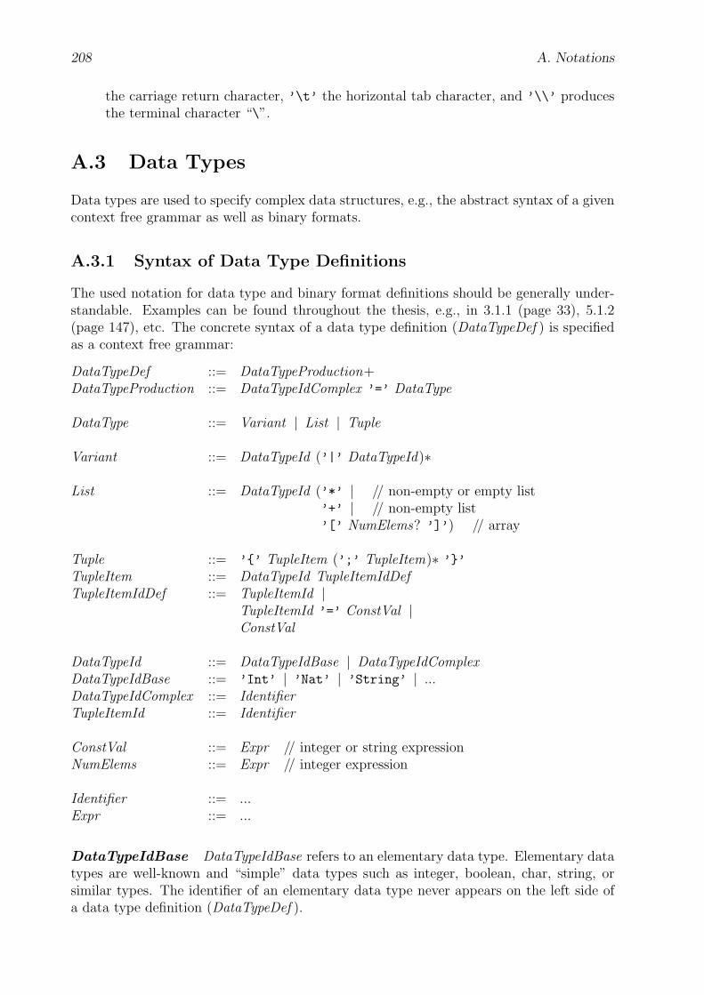
208 A. Notations
the carriage return character, ’\t’ the horizontal tab character, and ’\\’ producesthe terminal character “\”.
A.3 Data Types
Data types are used to specify complex data structures, e.g., the abstract syntax of a givencontext free grammar as well as binary formats.
A.3.1 Syntax of Data Type Definitions
The used notation for data type and binary format definitions should be generally under-standable. Examples can be found throughout the thesis, e.g., in 3.1.1 (page 33), 5.1.2(page 147), etc. The concrete syntax of a data type definition (DataTypeDef ) is specifiedas a context free grammar:
DataTypeDef ::= DataTypeProduction+DataTypeProduction ::= DataTypeIdComplex ’=’ DataType
DataType ::= Variant | List | Tuple
Variant ::= DataTypeId (’|’ DataTypeId)∗
List ::= DataTypeId (’*’ | // non-empty or empty list’+’ | // non-empty list’[’ NumElems? ’]’) // array
Tuple ::= ’{’ TupleItem (’;’ TupleItem)∗ ’}’TupleItem ::= DataTypeId TupleItemIdDefTupleItemIdDef ::= TupleItemId |
TupleItemId ’=’ ConstVal |ConstVal
DataTypeId ::= DataTypeIdBase | DataTypeIdComplexDataTypeIdBase ::= ’Int’ | ’Nat’ | ’String’ | ...DataTypeIdComplex ::= IdentifierTupleItemId ::= Identifier
ConstVal ::= Expr // integer or string expressionNumElems ::= Expr // integer expression
Identifier ::= ...Expr ::= ...
DataTypeIdBase DataTypeIdBase refers to an elementary data type. Elementary datatypes are well-known and “simple” data types such as integer, boolean, char, string, orsimilar types. The identifier of an elementary data type never appears on the left side ofa data type definition (DataTypeDef ).
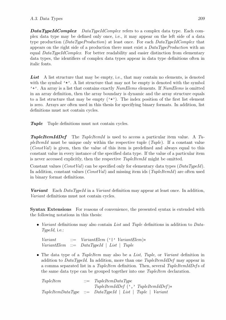
A.3. Data Types 209
DataTypeIdComplex DataTypeIdComplex refers to a complex data type. Each com-plex data type may be defined only once, i.e., it may appear on the left side of a datatype production (DataTypeProduction) at least once. For each DataTypeIdComplex thatappears on the right side of a production there must exist a DataTypeProduction with anequal DataTypeIdComplex. For better readability and easier distinction from elementarydata types, the identifiers of complex data types appear in data type definitions often initalic fonts.
List A list structure that may be empty, i.e., that may contain no elements, is denotedwith the symbol ’*’. A list structure that may not be empty is denoted with the symbol’+’. An array is a list that contains exactly NumElems elements. If NumElems is omittedin an array definition, then the array boundary is dynamic and the array structure equalsto a list structure that may be empty (’*’). The index position of the first list elementis zero. Arrays are often used in this thesis for specifying binary formats. In addition, listdefinitions must not contain cycles.
Tuple Tuple definitions must not contain cycles.
TupleItemIdDef The TupleItemId is used to access a particular item value. A Tu-pleItemId must be unique only within the respective tuple (Tuple). If a constant value(ConstVal) is given, then the value of this item is predefined and always equal to thisconstant value in every instance of the specified data type. If the value of a particular itemis never accessed explicitly, then the respective TupleItemId might be omitted.
Constant values (ConstVal) can be specified only for elementary data types (DataTypeId).In addition, constant values (ConstVal) and missing item ids (TupleItemId) are often usedin binary format definitions.
Variant Each DataTypeId in a Variant definition may appear at least once. In addition,Variant definitions must not contain cycles.
Syntax Extensions For reasons of convenience, the presented syntax is extended withthe following notations in this thesis:
• Variant definitions may also contain List and Tuple definitions in addition to Data-TypeId, i.e.:
Variant ::= VariantElem (’|’ VariantElem)∗VariantElem ::= DataTypeId | List | Tuple
• The data type of a TupleItem may also be a List, Tuple, or Variant definition inaddition to DataTypeId. In addition, more than one TupleItemIdDef may appear ina comma separated list in a TupleItem definition. Then, several TupleItemIdDef s ofthe same data type can be grouped together into one TupleItem declaration.
TupleItem ::= TupleItemDataTypeTupleItemIdDef (’,’ TupleItemIdDef )∗
TupleItemDataType ::= DataTypeId | List | Tuple | Variant
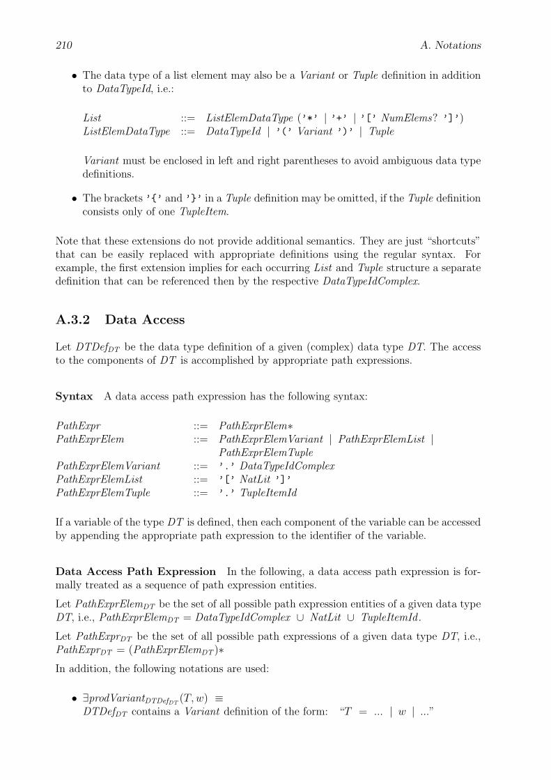
210 A. Notations
• The data type of a list element may also be a Variant or Tuple definition in additionto DataTypeId, i.e.:
List ::= ListElemDataType (’*’ | ’+’ | ’[’ NumElems? ’]’)ListElemDataType ::= DataTypeId | ’(’ Variant ’)’ | Tuple
Variant must be enclosed in left and right parentheses to avoid ambiguous data typedefinitions.
• The brackets ’{’ and ’}’ in a Tuple definition may be omitted, if the Tuple definitionconsists only of one TupleItem.
Note that these extensions do not provide additional semantics. They are just “shortcuts”that can be easily replaced with appropriate definitions using the regular syntax. Forexample, the first extension implies for each occurring List and Tuple structure a separatedefinition that can be referenced then by the respective DataTypeIdComplex.
A.3.2 Data Access
Let DTDefDT be the data type definition of a given (complex) data type DT. The accessto the components of DT is accomplished by appropriate path expressions.
Syntax A data access path expression has the following syntax:
PathExpr ::= PathExprElem∗PathExprElem ::= PathExprElemVariant | PathExprElemList |
PathExprElemTuplePathExprElemVariant ::= ’.’ DataTypeIdComplexPathExprElemList ::= ’[’ NatLit ’]’
PathExprElemTuple ::= ’.’ TupleItemId
If a variable of the type DT is defined, then each component of the variable can be accessedby appending the appropriate path expression to the identifier of the variable.
Data Access Path Expression In the following, a data access path expression is for-mally treated as a sequence of path expression entities.
Let PathExprElemDT be the set of all possible path expression entities of a given data typeDT, i.e., PathExprElemDT = DataTypeIdComplex ∪ NatLit ∪ TupleItemId .
Let PathExprDT be the set of all possible path expressions of a given data type DT, i.e.,PathExprDT = (PathExprElemDT )∗
In addition, the following notations are used:
• ∃prodVariantDTDefDT(T,w) ≡
DTDefDT contains a Variant definition of the form: “T = ... | w | ...”

A.3. Data Types 211
• ∃prodListDTDefDT(T,A,w) ≡
DTDefDT contains a List definition of the form:“T = A*”, “T = A+”, “T = A[]”, or “T = A[N]” and w is a valid indexposition. Valid index positions are integer numbers greater than or equal to zero.If the List definition is of the form “T = A[N]”, then the valid index positionsadditionally must be smaller then N .
• ∃prodTupleDTDefDT(T,A,w) ≡
DTDefDT contains a Tuple definition of the form: “T = { ...; A w; ... }”
Type Let p, v ∈ PathExprDT ∧ w ∈ PathExprElemDT . TDT (p) is the type of the pathexpression p and defined as follows:
TDT (p) = DT , if p = εw, if p = v ◦ w ∧ ∃prodVariantDTDefDT
(T (v), w)A, if p = v ◦ w ∧ ∃prodListDTDefDT
(T (v), A, w)A, if p = v ◦ w ∧ ∃prodTupleDTDefDT
(T (v), A, w)⊥, else
Valid Data Access Path Expressions PDT is the set of all possible and valid pathexpressions of DT. PDT is defined as follows:
p ∈ PDT ⇔def p = ε∨p = v ◦ w ∧ p ∈ PathExprDT ∧ w ∈ PathExprElemDT ∧ v ∈ PDT ∧(∃prodVariantDTDefDT
(T (v),w) ∨ ∃prodListDTDefDT(T (v),A,w) ∨
∃prodTupleDTDefDT(T (v),A,w))
Data Structure Trees All valid path expressions can be grouped into data structuretrees. All tree nodes are path expression entities. A data structure tree is a subset of PDT
where for each variant node exactly one possibility is chosen, i.e., all path expressions inthe tree that contain this variant node have the save variant type for this variant node.TRDT is the set of all possible data structure trees of a given data type DT and definedas follows:
t ∈ TRDT ⇔def ε ∈ t∧v ◦ w ∈ t⇒ v ∈ t∧(v ∈ t ∧ ∃prodVariantDTDefDT
(T (v),w1 )⇒(∃prodVariantDTDefDT
(T (v),w2 ) : v ◦ w2 ∈ t)∧(∀w3 ∈ PathExprElemDT : v ◦ w3 ∈ t⇒ w3 = w2))∧(v ∈ t ∧ ∃prodTupleDTDefDT
(T (v), A, w1)⇒(∀w2 ∈ PathExprElem : ∃prodTupleDTDef DT (T (v),w2 )⇒ v ◦ w2 ∈ t)∧
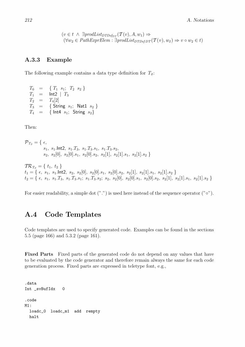
212 A. Notations
(v ∈ t ∧ ∃prodListDTDefDT(T (v), A, w1)⇒
(∀w2 ∈ PathExprElem : ∃prodListDTDef DT (T (v),w2 )⇒ v ◦ w2 ∈ t)
A.3.3 Example
The following example contains a data type definition for T0 :
T0 = { T1 s1; T2 s2 }T1 = Int2 | T3
T2 = T4[2]T3 = { String s1; Nat1 s2 }T4 = { Int4 s1; String s2}
Then:
PT0 = { ε,s1, s1.Int2, s1.T3, s1.T3.s1, s1.T3.s2,s2, s2[0], s2[0].s1, s2[0].s2, s2[1], s2[1].s1, s2[1].s2 }
TRT0 = { t1, t2 }t1 = { ε, s1, s1.Int2, s2, s2[0], s2[0].s1, s2[0].s2, s2[1], s2[1].s1, s2[1].s2 }t2 = { ε, s1, s1.T3, s1.T3.s1; s1.T3.s2; s2, s2[0], s2[0].s1, s2[0].s2, s2[1], s2[1].s1, s2[1].s2 }
For easier readability, a simple dot (”.”) is used here instead of the sequence operator (”◦”).
A.4 Code Templates
Code templates are used to specify generated code. Examples can be found in the sections5.5 (page 166) and 5.3.2 (page 161).
Fixed Parts Fixed parts of the generated code do not depend on any values that haveto be evaluated by the code generator and therefore remain always the same for each codegeneration process. Fixed parts are expressed in teletype font, e.g.,
.dataInt _svBufIdx 0
.codeM1:loadc_0 loadc_m1 add remptyhalt
A.4. Code Templates 213
Variable Parts Variable parts of the generated code depend on context values that haveto be first evaluated by the code generator and therefore might be different after each codegeneration process. Variable parts are enclosed with “<Variable Part>”. The descriptionof Variable Part is not bound to a particular format, but must be comprehensible from thecontext.
For example,
.<cvmProfile.cvmMode>Bit
results in the generated code
.16Bit
if the value of the term cvmProfile.cvmMode, which depends on the requesting client, isevaluated to 16 during the generation process.
Conditional Parts Conditional parts are expressed with
<if : Condition1 >
... // code template<elseif : Condition2 >
... // code template...<elseif : Conditionn> // n ≥ 1
... // code template<else>
... // code template<end>
The code template for Conditioni (1 ≥ i ≥ n), i.e., the ith condition, is only inserted, ifthe ith condition is met. The description of the ith condition is not bound to a particularformat, but must be comprehensible from the context. Note that the <elseif : ...> partsand the <else> part are optional.
For example,
printf ("
<if : cvmProfile.cvmMode = 16>
16
<elseif : cvmProfile.cvmMode = 32>
32
<else>
not 16 and not 32
<end>
");
results in the generated code
printf ("16");
orprintf ("32");
orprintf ("not 16 and not 32");
if the term cvmProfile.cvmMode evaluates to 16, 32, or any other value, respectively.
214 A. Notations
Iterative Parts Iterative parts are expressed with
<∀ Expression>
... // code template<end>
Expression must evaluate to an expression, where an element is selected from a set ofelements. The set of elements is defined in Expression as well. The inner part of the codetemplate specifies the generated code for each element of the set, whereby the element mayappear as a variable. Note that the set is processed in an ascending order.
For example,
<∀ i : 0 ≤ i ≤ 2>
printf ("<i>");
<end>
results in the generated code
printf ("0");
printf ("1");
printf ("2");
Imported Parts Imported parts are expressed with
<import : Verbal Description >
Verbal Description contains the information which code template is inserted here.
For example,
<import : Code of the example in the previous subsection “Variable Parts”>
results in the generated code
.16Bit
Functions A function definition is expressed with
<fct : id(parDeclarations)>... // code template
<end>
id contains the (unique) name of the function. parDefinitions contains an optional list ofparameter declarations. A formal syntax for the declaration of the parameter list is notspecified here.
A function call is expressed with
<call : id(parValues)>
id refers to the defined function with the same id. parValues defines values for the functionparameters, if available.
For example,
<fct : max (Int i1 , Int i2 )><if : i1 > i2>
<i1>

A.4. Code Templates 215
<else>
<i2>
<end>
<end>
printf ("<call : max (2 , 5 )>");
results in the generated code
printf ("5");
Verbal Description of Instruction Blocks A block of CVM instructions that per-forms a certain task might be described verbally, i.e., without listing the particular CVMinstructions in detail, by using the notation “<Verbal Description>”. Verbal descriptionsof instruction blocks are used in code templates for reasons of brevity and clearness, evenif the instruction block contains only fixed parts of the generated code.
For example, the CVM assembler code fragment in section 3.1.4.2 (page 39) contains verbaldescriptions of instruction blocks. Refer to section B (page 216) for more information onthe CVM assembler.
Appendix B
CVM Assembler (CVMA)
In this thesis an assembler for writing CVM programs, called the CVM assembler, has beendeveloped and implemented. The CVM assembler translates readable CVM programs intobinary CVM packets that are executed by the CVM. The CVM assembler can be usedas a low-level language to write user interfaces or other programs for the CVM. It is alsoused in the code templates to describe the code that is generated by the CVM packetgenerator. This section specifies in detail its use. At the end, some example programs andtheir disassembled binaries are listed.
B.1 Syntax
CVM assembler programs are case sensitive. The grammar for the concrete syntax ofthe CVM assembler is presented in a generally understandable notation. Refer to sectionA.2 (page 207) for a short description of the used notation. The grammar of the CVMassembler can be split into a syntactic and a lexical part. First, the grammar is listed,then additional explanations and context conditions are provided for particular syntacticconstructs in alphabetical order.
Syntactic Grammar The syntactic part of the grammar with the root CvmAsProg isas follows:
CvmAsProg ::= Mode? (CvmAsEntity)∗CvmAsEntity ::= Const | Data | Code
Mode ::= ’.16Bit’ | ’.16BitEmu’ | ’.32Bit’ | ’.32BitEmu’
Const ::= ’.const’ (Identifier Expr)∗
Data ::= ’.data’ (DeclVar Expr?)∗DeclVar ::= DataType Identifier
Code ::= ’.code’ (DeclFct | Label | Instruction)∗DeclFct ::= ’.fct’ Identifier ’(’ DeclPars ’)’ DataType? BlockDeclPars ::= (DeclVar (’,’ DeclVar)∗)?
216

B.1. Syntax 217
Block ::= ’{’ (Block | DeclVar | Label | Instruction)∗ ’}’Instruction ::= Mnemonic (Expr (’,’ Expr)∗)?
Expr ::= MulExpr | Expr (’+’ | ’-’) MulExprMulExpr ::= Factor | MulExpr (’*’ | ’/’ | ’%’) FactorFactor ::= ’(’ Expr ’)’ | ’-’ Factor | NatLiteral | StringLiteral |
Identifier | EventCode | FontCode | KeyCode | MouseFontCode |LibFctCode | BuiltinFct ’(’ (Expr (’,’ Expr)∗)? ’)’ |ArrayInit
ArrayInit ::= ’[’ (ArrayElem (’,’ ArrayElem)∗ )? ’]’
ArrayElem ::= Expr (’#’ Expr)?
Lexical Grammar The lexical part of the grammar is as follows:
BuiltinFct ::= ... // refer to section B.4 (page 227), “builtin function name”DataType ::= ... // refer to section B.2 (page 222), “DataType”EventCode ::= ... // refer to section 3.1.6.4 (page 49), “event code name”FontCode ::= ... // refer to section 3.2.3 (page 79), “font code name”KeyCode ::= ... // refer to section 3.3 (page 81), <X11/keysymdef.h>MouseFontCode ::= ... // refer to section 3.5 (page 81), <X11/cursorFont.h>LibFctCode ::= ... // refer to section 3.5 (page 83), “library function name”
Mnemonic ::= CvmMnemonic | MacroMnemonicCvmMnemonic ::= ... // refer to section 3.9.2 (page 100), “mnemonic”MacroMnemonic ::= ... // refer to section B.3 (page 224), “macro mnemonic”
Identifier ::= Alpha (Alpha | Digit )∗Label ::= Identifier ’:’
NatLiteral ::= Digit+StringLiteral ::= ’"’ (ASCII \ ’"’)∗ (’\\"’ (ASCII \ ’"’)∗ )∗ ’"’
Alpha ::= ’a’..’z’ | ’A’..’Z’ | ’_’Digit ::= ’0’..’9’
WhiteSpace ::= ’ ’ | ’\f’ | ’\n’ | ’\r’ | ’\t’Comment ::= ’/*’ ASCII∗ \ (ASCII∗ ’*/’ ASCII∗) ’*/’ |
’//’ ASCII∗ \ (ASCII∗ ’\n’ ASCII∗) ’\n’
To resolve ambiguities within the lexical part of the grammar, the longest possible charactersequence of the input program that matches one of the productions in the lexical grammar isselected. For example, the character sequence ’abc12’ is recognized as one Identifier, andnot as the Identifier ’abc’ followed by the NatLiteral ’12’. In addition, the charactersequence ’abc12:’ is recognized as a Label. If the longest possible character sequencematches more than one production, the production listed first is chosen.
White space characters (WhiteSpace) and comments (Comment) are discarded at lexicallevel. They may appear at any place in the CVM program between the syntactic units

218 B. CVM Assembler (CVMA)
listed in the syntactic part of the grammar.
ArrayInit This syntactic construct initializes a data array. The value of each arrayelement (ArrayElem) might be either an integer number, a string, or the result of thebuiltin function stringBytes(). Nested ArrayInits are not allowed.
If the value of an array element is a string, it consists only of one expression (Expr) whichmight be a single string literal (StringLiteral), or a single identifier (Identifier) that refer-ences a string constant declaration (DeclConst), or a single builtin function (BuiltinFct)call that returns a string, or a concatenation of two string expressions with the ’+’ oper-ator.
If the value of an array element is an integer number, the first expression (Expr) definesthe value whereas the optional second expression (Expr) sets the number of bytes thatshould be reserved for the value of the array element. However, the second expression isnot allowed, if the type and length of the array element is already known from the context.For example, this is the case, if ArrayInit is used to declare an event table. Refer toEventTable in section B.2 (page 223) for more information on declaring event tables. Ifthe second expression is allowed, but not explicitly given, then the default byte length ofthe array element is defined by the CVM mode (Mode). If the CVM mode is ’.16Bit’ or’.16BitEmu’, the byte length is 2. If the CVM mode is ’.32Bit’ or ’.32BitEmu’, thebyte length is 4. The value of an existent second expression may only be 1 or 2, if theCVM mode is ’.16Bit’ or ’.16BitEmu’, and 1, 2, 3, or 4, if the CVM mode is ’.32Bit’or ’.32BitEmu’. The identifiers (Identifier) that appear inside the second expression mustnot refer to labels (Label), functions (DeclFct), function parameters, and local or globalvariables (DeclVar). Neither, the byte length of the array element — no matter whetherspecified explicitly or implicitly — may be less than the minimum number of bytes thatare required for the value of the array element, with using one’s-complement format forpositive integer values and two’s-compliment format for negative integer values.
If the value of an array element is the result of the builtin function stringBytes(), thenit consists only of one expression which contains only the respective builtin function call(BuiltinFct). Refer to section B.4 (page 230) for more information on the builtin functionstringBytes().
Const This syntactic construct contains integer and string constant declarations. Arrayconstant declarations are not allowed. A declaration of an integer or string constant assignsthe integer or string value of the given expression (Expr) to the identifier (Identifier).The integer or string value is evaluated by the CVM assembler during assembling. Adeclared constant can be used within the whole CVM assembler program. As in anyother programming language, the use of self-defined constants makes programming moreconvenient and programs more readable.
If the value of the expression (Expr) is an integer number, the identifiers that appearinside that expression may only refer to labels (Label), functions (DeclFct), global variables(DeclVar), and other integer constants (DeclConst).
If the value of the expression (Expr) is a string, the expression may only consist of a singlestring literal (StringLiteral), or of a single identifier that references another string constantdeclaration (DeclConst), or of a single builtin function (BuiltinFct) call that returns astring, or of a concatenation of two string expressions with the ’+’ operator.

B.1. Syntax 219
Cyclic definitions of integer or string constants are not allowed, either.
Data This syntactic construct contains global variable declarations. Section B.2 (page222) describes for each CVM assembler data type the purpose of Expr, which might repre-sent an initial value or specify the data type further. Variables with an initial value appearin CVM memory in the Declared Data section. Variables with no initial value appear inCVM memory in the Undeclared Data section.
If the CVM mode (Mode) is ’.16Bit’ or ’.32Bit’, the CVM assembler sorts the declareddata automatically in the following order before assembling them into the CVM packet:
1. Uninitialized byte array declarations (Bytes)
2. Uninitialized integer declarations (Int)
3. Zero-initialized byte array declarations (Bytesz)
4. Zero-initialized integer declarations (Int)
5. Non-zero initialized byte array declarations (Bytesz)
6. Non-zero initialized integer declarations (Int)
7. String declarations (String)
8. Event table declarations (EventTable)
Note that there may be several event table declarations, but at most one event table isactive at a moment during execution.
If the initial value of an integer declaration depends on a memory address, i.e., there isan identifier inside the expression (Expr) of the initial value that refers to a label (Label),function (DeclFct), or global variable (DeclVar), then this declaration appears in the non-zero initialized integer declaration section. Otherwise, the CVM assembler cannot performthe address resolution correctly.
If the CVM mode (Mode) is ’.16Bit’ or ’.32Bit’, the CVM assembler does not assemblethe uninitialized data items into the CVM packet, which reduces packet size and thus net-work bandwidth requirements. In addition, the CVM assembler groups the zero-initializeddata items into one byte array using one of the bytesz<1|...|4> declaration codes and thenon-zero initialized data items except for the event table into another byte array using oneof the bytes<1|...|4> declaration codes. For the event table it uses the eventtable declara-tion code. Refer to section 3.8 (page 96) for a complete list of all CVM data declarationcodes.
If the CVM mode (Mode) is ’.16BitEmu’ or ’.32BitEmu’, the CVM assembler encodeseach data item into the CVM packet separately using the appropriate declaration code.Uninitialized data is then declared as zero initialized data in the CVM packet.

220 B. CVM Assembler (CVMA)
DeclFct A function declaration (or equally called procedure declaration) consists mainlyof the following parts: the name (Identifier) of the function, possibly the declaration of itsparameters (DeclPars) and return type (DataType), and finally the function body (Block).As specified in the grammar, nested declarations of functions are not possible. The datatype of an existing return value may only be Int. If the function does not have a returnvalue, the return type is Void or may be omitted. Variables (DeclVar) declared within aBlock are local variables. They are located on the CVM’s memory stack during executionof the CVM program. The CVM assembler inserts automatically CVM instructions toreserve space for them on the stack. The data type of a parameter or local variable mayonly be Int. The scope of a parameter is the whole function body. The scope of a localvariable is the rest of the block where it is declared, including all nested sub-blocks. Aparameter or local variable must not be redeclared within its scope to overwrite or hide itsfirst declaration. The CVM assembler inserts automatically the following CVM instructionsat the beginning of the function body to set the new stack frame:
loadc ((byteLen(result) +∑n
i=1 byteLen(pari)) / cvmIntLen)newstackframe
(loadc numLocalVariablesaddsp)?
byteLen(result) +∑n
i=1 byteLen(pari) represents the total amount of bytes for the returnvalue and the function parameters and cvmIntLen is 2 on a 16-bit CVM and 4 on a 32-bitCVM. numLocalVariables represents the total number of stack cells that are reserved forthe local variables of the function on the memory stack. If it is zero, than no space isreserved for them with the loadc and addsp instructions. Note that because of the limitedscopes of the local variables within the nested block structure, different local variables withdifferent scopes might be mapped to the same memory stack cell.
The instruction ret is not allowed within the function body, whereas the macro return mustoccur at least once. Refer to section B.3 (page 226) for more information on return.
Function declarations provide a higher means for writing functions (or procedures) in CVMassembler. However, they are not essential because the common low level way of writingfunctions in assembler is also possible. But used together with appropriate macros theaccess of parameters, local variables, and the return value gets more convenient to theCVM assembler programmer. This is illustrated by the example program in section B.6(page 237).
DeclVar DeclVar is used for declaring global variables within the Data section andlocal variables and parameters within a function declaration (DeclFct). In a variable orparameter declaration first comes the data type (DataType) of the variable, then its name(Identifier).
Expr The value of an expression (Expr) might be an integer number, a string, or a dataarray and is evaluated by the CVM assembler during assembling.
If its value is a string, then the expression consists of a single string literal (StringLiteral), orof a single identifier (Identifier) that references a string constant declaration (DeclConst),or of a single builtin function (BuiltinFct) call that returns a string, or of a concatenationof two string expressions with the ’+’ operator.

B.1. Syntax 221
If its value is a data array, then the expression consists only of a single array initialization(ArrayInit) or of a single builtin function (BuiltinFct) call that returns a data array. Referto Identifier for more information on the values of identifiers that appear as factors (Fac-tor) within expressions. The values of BuiltinFct, EventCode, FontCode, MouseFontCode,KeyCode, and LibFctCode are specified in the sections that are referred to in the commentsof the respective productions in the lexical grammar specification.
All arithmetic operations with integer numbers are based on integer but not floating pointarithmetic.
Identifier Lexically, an identifier (Identifier) must not match a BuiltinFct, DataType,EventCode, FontCode, MouseFontCode, KeyCode, LibFctCode, and a Mnemonic. An iden-tifier is used for declaring constants (DeclConst), labels (Label), functions (DeclFct), globaland local variables (DeclVar), and function parameters (DeclVar). Each identifier of a con-stant, label, function, and global variable may be used in a declaration only once and mustbe unique in the whole CVM assembler program. Either it must not be reused to declarea parameter or local variable of a function.
An identifier (Identifier) might appear as a factor (Factor) within an expression (Expr)and refer either to an integer or string constant (DeclConst), a label (Label), a function(DeclFct), a function parameter (DeclVar), a global variable (DeclVar), or a local variable(DeclVar) that is valid where the identifier appears. If it refers to a string constant itsvalue is the declared string. Otherwise, the value of the identifier is an integer value —that will be called in the following valId — and is calculated depending on the type of itsappropriate declaration:
• DeclConstvalId is the value of the expression (Expr) within the integer constant declarationDeclConst.
• DeclFctThis declaration type is treated like a Label. Refer to Label.
• DeclVarIf the variable is global, valId is the absolute memory address of the variable in theDeclared or Undeclared Data section in CVM memory. If the variable is a parameteror local variable, then valId is the relative memory address of the parameter or localvariable on the current stack frame starting from the address given by the specialregister regBP. Refer also to section 3.1.4.2 (page 39). Note that because of thelimited scopes of the local variables within the nested block structure, different localvariables with different scopes might be mapped to the same memory stack cell.
• Label :valId is the memory address of the next following instruction. If there is no instruc-tion following this label, then valId is the memory address of the previous instruc-tion plus its byte length. If there is no previous instruction, either, then valId isequal to codeSegmentAdr. Refer to section 3.8 (page 95) for more information oncodeSegmentAdr.
222 B. CVM Assembler (CVMA)
Instruction The grammar for Instruction defines the general syntax of an instruction.Instructions can be classified into CVM instructions and macros which act as pseudo in-structions. The operands and additional context conditions of the CVM instructions areexplained in section 3.9.2 (page 100), of the macros in section B.3 (page 224).
Label As usual, a label declares symbolically the memory address of its next followinginstruction.
Mode This syntactic construct specifies the CVM mode. If it is not explicitly specified,’.32BitEmu’ is used as default. Refer to section 3.1.2 (page 33) for more informationon CVM modes. In the following, the term “16-bit CVM” is used to refer that Modeis ’.16Bit’ or ’.16BitEmu’, and the term “32-bit CVM” is used to refer that Mode is’.32Bit’ or ’.32BitEmu’.
NatLiteral If the positive integer number specified by NatLiteral exceeds the maximumvalue 231 − 1, it is truncated automatically to that limit by the CVM assembler.
StringLiteral A string literal is a sequence of ASCII [7] characters. The number ofASCII characters in the ASCII sequence need not equal to the number of characters inthe produced string. For example, the escape characters for line feed, carriage return,and horizontal tab are represented by the ASCII character sequences “\n”, “\r”, and“\t”, respectively. The “"” character is represented by the ASCII character sequence“\"”. In addition, each character in a string literal may also be represented by its Unicode[88] number in the form \U{hexadecimal unicode number}. For example, the string literal"K\U{F6}nig" produces the string “Konig”. Note that the binary UTF-8 representationof the produced string must not exceed 65535 bytes.
B.2 Data Types
The CVM assembler provides the following data types: Bytes, Bytesz, EventTable, Int,and Void. In the following, the purpose of the syntactic unit Expr from the grammarspecification to declare and possibly initialize variables within the Data section will bedescribed by using the following description format:
data type valueverbose description
value is shown in the form identtype . ident can be any identifier and is chosen to characterizethe usage of value. type specifies the syntactic type of value and must be a syntactic subtypeof Expr, i.e., it can be derived from Expr according to the grammar specification in sectionB.1 (page 216). value must match the production for type. For example, numExpr mightbe used to specify a number that matches the production for Expr. Afterwards, someadditional explanations are given.
Note that for some data types several different kinds of values are possible. Each possibilityis listed separately.
B.2. Data Types 223
Bytes numBytesExpr
The data type Bytes declares a byte array without initializing it. The value of the ex-pression numBytes specifies the byte length of the array. It must be an unsigned integernumber in the range of [1; 216−1] on a 16-bit CVM or [1; 232 − 1] on a 32-bit CVM, respec-tively, and must not depend on labels (Label), functions (DeclFct), function parameters,and local or global variables (DeclVar).
Bytes textExpr
The data type Bytes declares an UTF-8 string and initializes it with the string expressiontextExpr .
Bytes arrayArrayInit
The data type Bytes declares a byte array and initializes it with array.
Bytes builtinFctNameBuiltinFct
The data type Bytes declares a byte array and initializes it with the byte array that isreturned by the builtin function with the name builtinFct. Refer to section B.4 (page 227for more information on builtin functions.
Bytesz numBytesExpr
The data type Bytesz declares a byte array and initializes all elements with zero. Theinteger value of the expression numBytes specifies the byte length of the array. It must bean unsigned integer number in the range of [1; 216−1] on a 16-bit CVM or [1; 232 − 1] ona 32-bit CVM, respectively, and must not depend on labels (Label), functions (DeclFct),function parameters, and local or global variables (DeclVar).
EventTable arrayArrayInit
The data type EventTable declares an event table. Here, the syntactic structure of ar-ray is a special form of an initialized byte array and must be ’[’ (eventCodeExpr ’,’
memAdrExpr)∗ ’]’. The value of eventCode must be an integer number greater than zero.If the value of eventCode is 1, then eventCode must be the second last element in the array.The value of memAdr must be an integer number greater than zero. Refer to sections 3.8(page 96) and 3.1.6.2 (page 48) for more information on event tables.
Int numExpr?The data type Int declares a signed (two’s complement) 2-byte integer number on a 16-bitCVM or a 4-byte integer number on a 32-bit CVM, respectively, with the optional initialvalue num. The value of num must be a signed (two’s complement) integer number in therange of [−215; 215 − 1] on a 16-bit CVM or [−231; 231 − 1] on a 32-bit CVM, respectively,
String textExpr
The data type String declares an UTF-8 string and initializes it with the string expressiontextExpr . If the CVM mode (Mode) is ’.16Bit’ or ’.32Bit’, this declaration equals to the“Bytes textExpr” declaration. Otherwise, the CVM assembler uses the CVM declarationcode string when assembling this data item into the CVM packet.

224 B. CVM Assembler (CVMA)
B.3 Macros
For reasons of convenience, the CVM assembler provides some predefined macros to simplifyprogramming in CVM assembler. A predefined macro contains several successive CVMinstructions and is used as a pseudo instruction. However, the predefined macros arestill quite low-level. The CVM assembler expands them into CVM instructions before itgenerates the binary code. In the following, the predefined macros are listed alphabeticallyand described using the following description format:
macro mnemonic operands −→ target instructionsverbose description
The left side contains the mnemonic of the macro and its (possibly empty) operand list.Each operand is shown in the form identtype . ident can be any identifier and is chosen tocharacterize the usage of the operand. type determines the syntactic type of the operandaccording to the grammar specification in section B.1 (page 216). The operand mustmatch the production for type. For example, varIdentifier might be used to specify a variablewhose name matches the production for Identifier. The right side contains the instructionsequence into which the macro is expanded. Afterwards, some additional explanations aregiven.
fcall fctIdIdentifier −→ loadcr fctIdIdentifier
call(loadc −numParsaddsp)?
The macro fcall first calls a declared function and then pops the function parameters — ifavailable — from the memory stack and discards them. Therefore, it assumes a functiondeclaration with fctId being the name of the function. numPars represents the totalnumber of stack cells occupied by the parameters on the memory stack. Each stack celloccupies cvmIntLen number of bytes. Refer to sections B.3 (page 225) and 3.1.2 (page 33)for more information on loadcr and cvmIntLen, respectively.
fcall I fctIdIdentifier , numExpr −→ loadc numExpr
pushfcall fctIdIdentifier
The macro fcall I calls a declared function with an integer parameter. The value of nummust be an integer number.
load varIdentifier −→ loadc adr(var)load<a|r>
The macro load loads the value of the signed 2- or 4-byte integer (Int) variable var onto theregister stack, depending on whether the CVM mode (Mode) is set to 16-bit (’.16Bit’,’.16BitEmu’) or 32-bit (’.32Bit’, ’.32BitEmu’). var must be a declared function pa-rameter, local variable, or global variable. adr(var) represents the memory address of var,which is absolute, if var is a global variable, otherwise relative. Section B.1 (page 221)explains how the correct memory address of the identifier var is determined. If var is a

B.3. Macros 225
global variable, the instruction loada is used, otherwise loadr. The benefit of this macrois that the CVM assembler programmer does not need to hardcode explicitly the loadinstruction, the memory address of the variable var, and the byte length of the memoryaddress of the variable var when retrieving its value from memory. All these informationsare included automatically by the CVM assembler into the resulting instructions.
loadc numExpr −→ loadc<ε|u><byteLen(val(num))> val(num)| loadc 0 | loadc 1 | loadc m1
The macro loadc loads the immediate integer number val(num) onto the register stack withval(num) representing the integer value of the expression num and byteLen(val(num)) ∈{1, 2, 3, 4} representing the minimum byte length that is required for val(num). If val(num)is negative, val(num) is encoded as a two’s-complement integer number, otherwise as aone’s-complement integer number. Depending on the algebraic sign of val(num) and itsbyte length, the CVM assembler expands this macro into one of the appropriate loadinstructions. byteLen(val(num)) must not exceed 2 on a 16-bit CVM or 4 on a 32-bitCVM, respectively. The benefit of this macro is that the CVM assembler programmerdoes not need to hardcode explicitly the algebraic sign and the required byte length ofval(num) into the load instruction. Note that this macro must not be the last instructionin a CVM assembler program, which simplifies address resolution for the CVM assemblerand does not cause any considerable restriction.
loadcr numExpr −→ loadc<ε|u><byteLen(relAdr)> relAdr| loadc 0 | loadc 1 | loadc m1
The macro loadcr loads the immediate integer number relAdr onto the register stack withrelAdr = val(num) − memAdr(nextInst). val(num) represents the integer value of theexpression num, memAdr(nextInst) represents the absolute memory address of the nextinstruction, and byteLen(relAdr) ∈ {1, 2, 3, 4} represents the minimum byte length that isrequired for relAdr . If relAdr is negative, relAdr is encoded as a two’s-complement integernumber, otherwise as a one’s-complement integer number. Depending on the algebraicsign of relAdr and its byte length, the CVM assembler expands this macro into one ofthe appropriate load instructions. byteLen(relAdr) must not exceed 2 on a 16-bit CVMor 4 on a 32-bit CVM, respectively. The benefit of this macro is that the CVM assemblerprogrammer does not need to hardcode explicitly the algebraic sign and the required bytelength of relAdr into the load instruction. This macro is used right before a jump or callinstruction to load the relative memory address of the jump target. Note that this macromust not be the last instruction in a CVM assembler program.
rcvpage pageNoExpr , subpageNoExpr −→ loadc hostAdrSrv
loadc pageNoloadc subpageNorcv
The macro rcvpage contacts the CVM packet server that serves the client and requestsfrom it the CVMUI page with the AUI page number pageNo and the AUI subpage numbersubpageNo. The values of pageNo and subpageNo must be integer numbers. Refer also tosection 5.5.1 (page 166) for more information on hostAdrSrv.
226 B. CVM Assembler (CVMA)
rcvpage a pageNoExpr , subpageNoMemAdrExpr −→ loadc hostAdrSrv
loadc pageNoloadc subpageNoMemAdrloadarcv
The macro rcvpage a is similar to the macro rcvpage. However, subpageNoMemAdr repre-sents the absolute memory address of subpageNo.
rcvsvc hostAdrMemAdrExpr , serviceNoExpr −→ sidzeroloadc hostAdrMemAdrloadc serviceNoloadc 0rcv
The macro rcvsvc starts a new client-server session with the addressed CVM packet serverand requests a CVMUI page that belongs to the interactive network service with the servicenumber serviceNoExpr . The AUI page and subpage numbers of the requested CVMUI pageare zero, each. The values of hostAdrMemAdr and serviceNo must be integer numbers.
retload −→ loadc 0loadr
The macro retload loads the current return value of the function from the memory stackonto the register stack for further processing. Therefore, it can only appear within thebody of a function declaration that has a return value. The benefit of this macro is thatthe CVM assembler programmer does not need to hardcode explicitly the relative memoryaddress of the return value.
retstore −→ loadc 0storer
The macro retstore pops the top-most value from the register stack and assigns it to thereturn value of the function in the memory stack. Therefore, it can only appear within thebody of a function declaration that has a return value. The benefit of this macro is thatthe CVM assembler programmer does not need to hardcode explicitly the relative memoryaddress of the return value.
return −→ (loadc −numLocVarsaddsp)?oldstackframeret
The macro return first pops the current available local variables from the memory stackand discards them. Then it sets back the previous stack frame and returns to the caller ofthis function. Therefore, it can only appear within the body of a function declaration. Inaddition, there must be at least one return instruction in each function body. numLocVarsrepresents the total number of stack cells that are occupied by the local variables on thememory stack. The benefit of this macro is that the CVM assembler programmer canreturn with one instruction conveniently back to the caller of the function.
B.4. Builtin Functions 227
sendrcvpage pageNoExpr , subpageNoExpr −→ loadc hostAdrSrv
loadc pageNoloadc subpageNoload svBufIdx
loadc svBuf
sendrcvThe macro sendrcvpage contacts the CVM packet server that serves the client, sends data toit and requests the CVMUI page with the AUI page number pageNo and the AUI subpagenumber subpageNo. The values of pageNo and subpageNo must be integer numbers. Referalso to section 5.5.1 (page 166) for more information on hostAdrSrv, svBufIdx, andsvBuf.
sendrcvpage a pageNoExpr , subpageNoMemAdrExpr −→ loadc hostAdrSrv
loadc pageNoloadc subpageNoMemAdrloadaload svBufIdx
loadc svBuf
sendrcvThe macro sendrcvpage a is similar to the macro sendrcvpage. However, subpageNoMemAdrrepresents the absolute memory address of subpageNo.
store varIdentifier −→ loadc adr(var)store<a|r>
The macro store stores the value on the top of the register stack into the integer (Int)variable var. var must be a declared function parameter, local variable, or global variable.adr(var) represents the memory address of var, which is absolute, if var is a global variable,or relative, if var is a parameter or local variable. Section B.1 (page 221) explains how thecorrect memory address of var (Identifier) is determined. Depending on the specified CVMmode (Mode), the byte length of the variable var is 2 on a 16-bit CVM and 4 on a 32-bitCVM. If var is a global variable, the instruction storea is used, otherwise storer. The benefitof this macro is that the CVM assembler programmer does not need to hardcode explicitlythe store instruction, the memory address of the variable var, and the byte length of thememory address of the variable var when storing a value into it. All these informationsare included automatically by the CVM assembler into the resulting instructions.
B.4 Builtin Functions
For reasons of convenience, the CVM assembler also provides some builtin functions tosimplify programming in CVM assembler. The CVM assembler processes a builtin functionduring assembling and writes the result into the binary code. In the following, the builtinfunctions are listed alphabetically and described using the following description format:
builtin function name (parameters) : return type
228 B. CVM Assembler (CVMA)
verbose description
builtin function name serves as a one-word description of the purpose of the function.parameters is a (comma separated and possibly empty) list of function parameters. Eachparameter is shown in the form identtype . ident can be any identifier and is usually chosento characterize the meaning of the parameter. type determines the syntactic type of theparameter according to the grammar specification in section B.1 (page 216). The parametermust match the production for type. For example, valExpr might be used to specify a valuethat matches the production for Expr. return type specifies the data type of the result andis one of the CVM data types Int, Nat, String, or a tuple structure. Afterwards, a verbosedescription of the builtin function is given.
bitmapFile (fileNameExpr) : { Nat<2|4> width, height;Nat1[width ∗ height] data }
The builtin function bitmapFile reads a bitmap image file that complies to the X11BitMap format XBM [96]. The name of the bitmap file is the value of the string expressionfileName. This builtin function returns the width and height of the bitmap image andthe image data as a byte array. If the CVM mode is set to a 32-bit CVM, i.e., Mode =’.32Bit’ or ’.32BitEmu’, the data types of width and height are each Nat4 and thewidth and height of the bitmap image must fit into the Nat4 data type. If the CVM modeis set to a 16-bit CVM, i.e., Mode = ’.16Bit’ or ’.16BitEmu’, the data types of width
and height are each Nat2 and the width and height of the bitmap image must fit into theNat2 data type. width and height are specified in pixels.
bitmapHeight (fileNameExpr) : IntbitmapWidth (fileNameExpr) : IntThe builtin functions bitmapHeight and bitmapWidth read a bitmap image file and returnits height and width in pixels, respectively. The bitmap image complies to the X11 BitMapformat XBM [96]. The name of the bitmap file is the value of the string expression fileName.
font (fontCodeExpr , fontSizeExpr) : Int4The builtin function font encodes the given font components into an appropriate Int4number according to the following format: (fontSize � 16) | fontCode. This builtinfunction can only be used, if the specified CVM mode is set to a 32-bit CVM, i.e., Mode= ’.32Bit’ or ’.32BitEmu’. The values of the expressions fontCode and fontSize mustbe unsigned integer numbers in the range of [0; 65535] and each of them must not dependon labels (Label), functions (DeclFct), function parameters, and local or global variables(DeclVar). fontSize is specified in pixels. Refer to section 3.2.3 (page 79) for a list of thecurrently supported font codes and their respective valid font sizes. Refer also to the CVMinstruction setfont32 (page 113).
fontPt (fontCodeExpr , fontSizeExpr) : Int4Same functionality as font(). However, fontSize is specified in tenths of a Point (pt), butnot in pixels.
B.4. Builtin Functions 229
fontAscent (fontCodeExpr , fontSizeExpr) : IntfontDescent (fontCodeExpr , fontSizeExpr) : IntfontHeight (fontCodeExpr , fontSizeExpr) : IntThe builtin functions fontAscent, fontDescent, and fontHeight return the ascent, de-scent, and height of a font in pixels. The height is the sum of its ascent and descent. Thefont is specified by fontCode and fontSize. The values of the expressions fontCode andfontSize must be unsigned integer numbers in the range of [0; 65535] and each of themmust not depend on labels (Label), functions (DeclFct), function parameters, and local orglobal variables (DeclVar). fontSize is specified in pixels. Refer to section 3.2.3 (page 79)for a list of the currently supported font codes and their respective valid font sizes.
fontAscentPt (fontCodeExpr , fontSizeExpr) : IntfontDescentPt (fontCodeExpr , fontSizeExpr) : IntfontHeightPt (fontCodeExpr , fontSizeExpr) : IntSame functionality as fontAscent(), fontDescent(), and fontHeight(), respectively.However, fontSize and the return value are specified in tenths of a Point (pt), but not inpixels.
MAX (num1Expr , num2Expr) : IntMIN (num1Expr , num2Expr) : IntThe builtin functions MAX and MIN return the maximum and the minimum of the twointeger values num1 and num2, respectively.
pixmapFile (fileNameExpr) : Nat1[ ] data
The builtin function pixmapFile reads a pixmap image file that complies to the X11PixMap format XPM [38]. The name of the pixmap file is the value of the string expressionfileName. This builtin function returns an ASCII [7] character string as a byte array thatrepresents an exact copy of the X PixMap (XPM) [38] file in memory. Note that the bytearray data does not contain the terminating null character.
pixmapHeight (fileNameExpr) : IntpixmapWidth (fileNameExpr) : IntThe builtin functions pixmapHeight and pixmapWidth read a pixmap image file and returnits height and width in pixels, respectively. The pixmap image complies to the X11 PixMapformat XPM [38]. The name of the pixmap file is the value of the string expression fileName.
rgb (redExpr , greenExpr , blueExpr) : Int4The builtin function rgb encodes the given red, green, and blue color components into anappropriate Int4 number according to the following format: (red � 16) | (green � 8) | blue.This builtin function can only be used, if the specified CVM mode is set to a 32-bit CVM,i.e., Mode = ’.32Bit’ or ’.32BitEmu’. The values of the expressions red, green, andblue must be unsigned integer numbers in the range of [0; 255] and each of them mustnot depend on labels (Label), functions (DeclFct), function parameters, and local or globalvariables (DeclVar). Refer also to the CVM instruction setcolor32 (page 112).
230 B. CVM Assembler (CVMA)
sizeof (valExpr) : IntThe builtin function sizeof returns the byte length of the value of the expression val. Itis similar to the sizeof operator of the C [20] programming language. If val is an integerexpression, then the builtin function returns 2 on a 16-bit CVM and 4 on a 32-bit CVM,respectively. If val is a string expression, then the builtin function returns the byte lengthof the corresponding String structure. Refer to section 3.1.1 (page 33) for more informationon the CVM type String. If val is an array expression, then the builtin function returnsthe number of bytes of the corresponding byte array. However, if val consists only of anidentifier (Identifier) that directly or indirectly refers to a variable declaration (DeclVar),then the builtin function returns the byte length of the declared data.
For example, in the following CVM assembler code fragment
.32Bit
.dataString d1 "123456789"
.constc1 d1c2 sizeof (c1)c3 sizeof ([32, 165, "Hello", 5321, sizeof ([9294, 12431, "World!", 4325]),
stringBytes ("Hello World!")])
the values of the integer constants c2 and c3 are 10 and 34, respectively.
stringBytes (textExpr) : Nat1[ ] data
The builtin function stringBytes returns the value of the string expression text as a bytearray of UTF-8 characters. Compared to the CVM type String, the returned byte arraydata equals to the bytes field of the corresponding String structure, but not to the wholeString structure. Refer to section 3.1.1 (page 33) for more information on the CVM typeString. For example, stringBytes("Hello World!\n") returns the byte array [72, 101,108, 108, 111, 32, 87, 111, 114, 108, 100, 33, 10], with each byte value represented here indecimal notation and separated by a comma. The whole corresponding String structure,however, equals to the byte array [13, 72, 101, 108, 108, 111, 32, 87, 111, 114, 108, 100,33, 10], again with each byte value represented here in decimal notation and separated bya comma. The first byte with the value 13 indicates the number of the following byteswithin the String structure.
textBreakLines (textExpr , fontCodeExpr , fontSizeExpr , maxWidthExpr) : StringThe builtin function textBreakLines formats the text paragraph text, which is a stringexpression, by inserting single line break characters (“\n”), so that the maximum widthof the resulting text paragraph, which is also a string, does not exceed the value of theinteger expression maxWidth. A text paragraph consists of one or more text lines that areseparated by the “\n” character. The width of a text paragraph is the maximum widthof all its text lines. A “\n” character can only be inserted right before a space character(“ ”), i.e., the words within text are not truncated. Note that no “\n” characters thatare already contained in text are removed in the resulting text paragraph. In addition,textBreakLines also truncates successive “ ” characters within text to one “ ” character
B.4. Builtin Functions 231
and ignores all “ ” characters right at the beginning and at the end of a text line in text.The used font is specified by fontCode and fontSize. The values of the expressions fontCodeand fontSize must be unsigned integer numbers in the range of [0; 65535] and each of themmust not depend on labels (Label), functions (DeclFct), function parameters, and local orglobal variables (DeclVar). fontSize and maxWidth are specified in pixels. Refer to section3.2.3 (page 79) for a list of the currently supported font codes and their respective validfont sizes.
For example, in the following CVM assembler code fragment
.conststr1 textBreakLines (
" This CVM program computes the nth Fibonacci number. \n " +" During the computation it counts the elapsed time. \n ",fontCourier, 12, 242)
the value of the string constant str1 is “This CVM program computes the nth\nFibonaccinumber.\nDuring the computation it counts\nthe elapsed time.\n”. When drawn on theCVM display with the instruction textp (page 116), this string corresponds to the followingtext paragraph:
This CVM program computes the nth
Fibonacci number.
During the computation it counts
the elapsed time.
textBreakLinesPt (textExpr , fontCodeExpr , fontSizeExpr , maxWidthPtExpr) : StringSame functionality as textBreakLines(). However, fontSize and maxWidthPt are speci-fied in tenths of a Point (pt), but not in pixels.
textHeight (textExpr , fontCodeExpr , fontSizeExpr , lineHeightExpr) : IntThe builtin function textHeight returns the height of the text paragraph text whichconsists of one or more text lines that are separated by the “\n” character. The heightof the text paragraph is the number of its text lines multiplied by height. If the value oflineHeight is less than or equal to zero, then height equals to the height of the used font.Otherwise, height equals to the value of lineHeight. The font is specified by fontCode andfontSize. The height of the font is the sum of its ascent and descent. text must be a stringexpression. The values of the expressions fontCode and fontSize must be unsigned integernumbers in the range of [0; 65535] and each of them must not depend on labels (Label),functions (DeclFct), function parameters, and local or global variables (DeclVar). fontSize,lineHeight, and the return value are specified in pixels. Refer to section 3.2.3 (page 79) fora list of the currently supported font codes and their respective valid font sizes.
textHeightPt (textExpr , fontCodeExpr , fontSizeExpr , lineHeightExpr) : IntSame functionality as textHeight(). However, fontSize, lineHeight, and the return valueare specified in tenths of a Point (pt), but not in pixels.
232 B. CVM Assembler (CVMA)
textWidth (textExpr , fontCodeExpr , fontSizeExpr) : IntThe builtin function textWidth returns the width of the text paragraph text which consistsof one or more text lines that are separated by the “\n” character. The width of the textparagraph is the maximum width of all its text lines. The used font is specified by fontCodeand fontSize. text must be a string expression. The values of the expressions fontCodeand fontSize must be unsigned integer numbers in the range of [0; 65535] and each of themmust not depend on labels (Label), functions (DeclFct), function parameters, and local orglobal variables (DeclVar). fontSize and the return value are specified in pixels. Refer tosection 3.2.3 (page 79) for a list of the currently supported font codes and their respectivevalid font sizes.
textWidthPt (textExpr , fontCodeExpr , fontSizeExpr) : IntSame functionality as textWidth(). However, fontSize and the return value are specifiedin tenths of a Point (pt), but not in pixels.
B.5 Implementation Notes
The CVM assembler has been implemented with the C [20] programming language underthe Linux [43] operating system. The used C compiler is gcc [32]. For the lexical andsyntactic analysis the scanner generator flex [33] and the parser generator bison [30]have been used, respectively. In addition to the CVM assembler, a CVM disassembler hasbeen implemented, as well. The implemented CVM assembler checks an input programthoroughly and produces a meaningful message for each detected error.
Source Files The C source files for the CVM assembler and disassembler are in thesubdirectories Implementation/CvmAssembler/Src/ and Implementation/RghLib/Src/.The latter subdirectory contains only source files whose names start with the prefix “rgh”.
• cvmAs.{h,c}: These source files contain the function cvmAs ascii2cvmp() and otherdefinitions and functions that are needed by the CVM assembler.
• cvmAsDisAs.{h,c}: These source files contain definitions and functions that areneeded both by the CVM assembler and by the CVM disassembler.
• cvmAsMain.c: This source file contains the main() function of the CVM assembler.It invokes the cvmAs ascii2cvmp() function.
• cvmAsNode.{h,c}: These source files contain the core parts of the CVM assembler.This includes the tree node constructors to build the syntax tree, the semantic checkof the context conditions, and the generation of the CVM packet, which contains theCVM binary code. The CVM program is dealt as a tree structure.
• cvmAsParse.y: This source file contains the syntactic grammar specification for theparser generator bison. The parser transforms the CVM assembler program into asyntax tree for further processing.
• cvmAsScan.l: This source file contains the lexical grammar specification for thescanner generator flex.
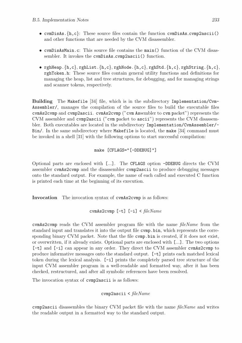
B.5. Implementation Notes 233
• cvmDisAs.{h,c}: These source files contain the function cvmDisAs cvmp2ascii()
and other functions that are needed by the CVM disassembler.
• cvmDisAsMain.c: This source file contains the main() function of the CVM disas-sembler. It invokes the cvmDisAs cvmp2ascii() function.
• rghHeap.{h,c}, rghList.{h,c}, rghNode.{h,c}, rghStd.{h,c}, rghString.{h,c},rghToken.h: These source files contain general utility functions and definitions formanaging the heap, list and tree structures, for debugging, and for managing stringsand scanner tokens, respectively.
Building The Makefile [34] file, which is in the subdirectory Implementation/Cvm-
Assembler/, manages the compilation of the source files to build the executable filescvmAs2cvmp and cvmp2ascii. cvmAs2cvmp (”cvm Assembler to cvm packet”) represents theCVM assembler and cvmp2ascii (”cvm packet to ascii”) represents the CVM disassem-bler. Both executables are located in the subdirectory Implementation/CvmAssembler/-
Bin/. In the same subdirectory where Makefile is located, the make [34] command mustbe invoked in a shell [31] with the following options to start successful compilation:
make [CFLAGS="[-DDEBUG]"]
Optional parts are enclosed with [...]. The CFLAGS option -DDEBUG directs the CVMassembler cvmAs2cvmp and the disassembler cvmp2ascii to produce debugging messagesonto the standard output. For example, the name of each called and executed C functionis printed each time at the beginning of its execution.
Invocation The invocation syntax of cvmAs2cvmp is as follows:
cvmAs2cvmp [-t] [-i] < fileName
cvmAs2cvmp reads the CVM assembler program file with the name fileName from thestandard input and translates it into the output file cvmp.bin, which represents the corre-sponding binary CVM packet. Note that the file cvmp.bin is created, if it does not exist,or overwritten, if it already exists. Optional parts are enclosed with [...]. The two options[-t] and [-i] can appear in any order. They direct the CVM assembler cvmAs2cvmp toproduce informative messages onto the standard output. [-t] prints each matched lexicaltoken during the lexical analysis. [-i] prints the completely parsed tree structure of theinput CVM assembler program in a well-readable and formatted way, after it has beenchecked, restructured, and after all symbolic references have been resolved.
The invocation syntax of cvmp2ascii is as follows:
cvmp2ascii < fileName
cvmp2ascii disassembles the binary CVM packet file with the name fileName and writesthe readable output in a formatted way to the standard output.
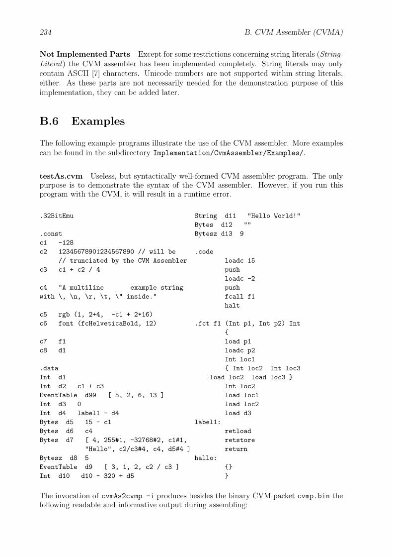
234 B. CVM Assembler (CVMA)
Not Implemented Parts Except for some restrictions concerning string literals (String-Literal) the CVM assembler has been implemented completely. String literals may onlycontain ASCII [7] characters. Unicode numbers are not supported within string literals,either. As these parts are not necessarily needed for the demonstration purpose of thisimplementation, they can be added later.
B.6 Examples
The following example programs illustrate the use of the CVM assembler. More examplescan be found in the subdirectory Implementation/CvmAssembler/Examples/.
testAs.cvm Useless, but syntactically well-formed CVM assembler program. The onlypurpose is to demonstrate the syntax of the CVM assembler. However, if you run thisprogram with the CVM, it will result in a runtime error.
.32BitEmu
.constc1 -128c2 12345678901234567890 // will be
// trunciated by the CVM Assemblerc3 c1 + c2 / 4
c4 "A multiline example stringwith \, \n, \r, \t, \" inside."
c5 rgb (1, 2+4, -c1 + 2*16)c6 font (fcHelveticaBold, 12)
c7 f1c8 d1
.dataInt d1Int d2 c1 + c3EventTable d99 [ 5, 2, 6, 13 ]Int d3 0Int d4 label1 - d4Bytes d5 15 - c1Bytes d6 c4Bytes d7 [ 4, 255#1, -32768#2, c1#1,
"Hello", c2/c3#4, c4, d5#4 ]Bytesz d8 5EventTable d9 [ 3, 1, 2, c2 / c3 ]Int d10 d10 - 320 + d5
String d11 "Hello World!"Bytes d12 ""Bytesz d13 9
.codeloadc 15pushloadc -2pushfcall f1halt
.fct f1 (Int p1, Int p2) Int{load p1loadc p2Int loc1{ Int loc2 Int loc3
load loc2 load loc3 }Int loc2load loc1load loc2load d3
label1:retloadretstorereturn
hallo:{}}
The invocation of cvmAs2cvmp -i produces besides the binary CVM packet cvmp.bin thefollowing readable and informative output during assembling:
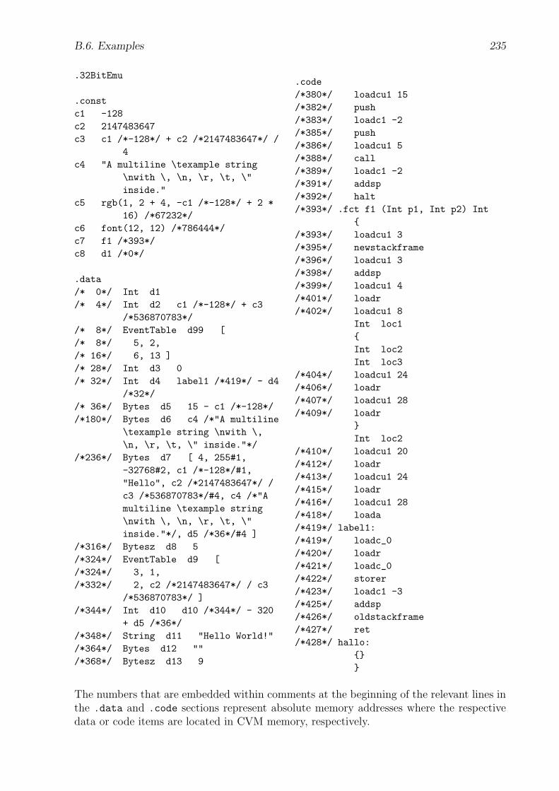
B.6. Examples 235
.32BitEmu
.constc1 -128c2 2147483647c3 c1 /*-128*/ + c2 /*2147483647*/ /
4c4 "A multiline \texample string
\nwith \, \n, \r, \t, \"inside."
c5 rgb(1, 2 + 4, -c1 /*-128*/ + 2 *16) /*67232*/
c6 font(12, 12) /*786444*/c7 f1 /*393*/c8 d1 /*0*/
.data/* 0*/ Int d1/* 4*/ Int d2 c1 /*-128*/ + c3
/*536870783*//* 8*/ EventTable d99 [/* 8*/ 5, 2,/* 16*/ 6, 13 ]/* 28*/ Int d3 0/* 32*/ Int d4 label1 /*419*/ - d4
/*32*//* 36*/ Bytes d5 15 - c1 /*-128*//*180*/ Bytes d6 c4 /*"A multiline
\texample string \nwith \,\n, \r, \t, \" inside."*/
/*236*/ Bytes d7 [ 4, 255#1,-32768#2, c1 /*-128*/#1,"Hello", c2 /*2147483647*/ /c3 /*536870783*/#4, c4 /*"Amultiline \texample string\nwith \, \n, \r, \t, \"inside."*/, d5 /*36*/#4 ]
/*316*/ Bytesz d8 5/*324*/ EventTable d9 [/*324*/ 3, 1,/*332*/ 2, c2 /*2147483647*/ / c3
/*536870783*/ ]/*344*/ Int d10 d10 /*344*/ - 320
+ d5 /*36*//*348*/ String d11 "Hello World!"/*364*/ Bytes d12 ""/*368*/ Bytesz d13 9
.code/*380*/ loadcu1 15/*382*/ push/*383*/ loadc1 -2/*385*/ push/*386*/ loadcu1 5/*388*/ call/*389*/ loadc1 -2/*391*/ addsp/*392*/ halt/*393*/ .fct f1 (Int p1, Int p2) Int
{/*393*/ loadcu1 3/*395*/ newstackframe/*396*/ loadcu1 3/*398*/ addsp/*399*/ loadcu1 4/*401*/ loadr/*402*/ loadcu1 8
Int loc1{Int loc2Int loc3
/*404*/ loadcu1 24/*406*/ loadr/*407*/ loadcu1 28/*409*/ loadr
}Int loc2
/*410*/ loadcu1 20/*412*/ loadr/*413*/ loadcu1 24/*415*/ loadr/*416*/ loadcu1 28/*418*/ loada/*419*/ label1:/*419*/ loadc_0/*420*/ loadr/*421*/ loadc_0/*422*/ storer/*423*/ loadc1 -3/*425*/ addsp/*426*/ oldstackframe/*427*/ ret/*428*/ hallo:
{}}
The numbers that are embedded within comments at the beginning of the relevant lines inthe .data and .code sections represent absolute memory addresses where the respectivedata or code items are located in CVM memory, respectively.
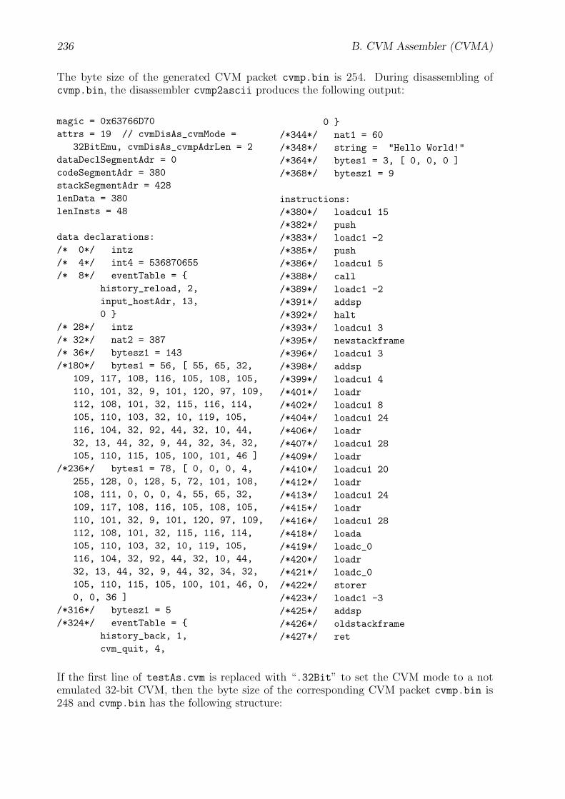
236 B. CVM Assembler (CVMA)
The byte size of the generated CVM packet cvmp.bin is 254. During disassembling ofcvmp.bin, the disassembler cvmp2ascii produces the following output:
magic = 0x63766D70attrs = 19 // cvmDisAs_cvmMode =
32BitEmu, cvmDisAs_cvmpAdrLen = 2dataDeclSegmentAdr = 0codeSegmentAdr = 380stackSegmentAdr = 428lenData = 380lenInsts = 48
data declarations:/* 0*/ intz/* 4*/ int4 = 536870655/* 8*/ eventTable = {
history_reload, 2,input_hostAdr, 13,0 }
/* 28*/ intz/* 32*/ nat2 = 387/* 36*/ bytesz1 = 143/*180*/ bytes1 = 56, [ 55, 65, 32,
109, 117, 108, 116, 105, 108, 105,110, 101, 32, 9, 101, 120, 97, 109,112, 108, 101, 32, 115, 116, 114,105, 110, 103, 32, 10, 119, 105,116, 104, 32, 92, 44, 32, 10, 44,32, 13, 44, 32, 9, 44, 32, 34, 32,105, 110, 115, 105, 100, 101, 46 ]
/*236*/ bytes1 = 78, [ 0, 0, 0, 4,255, 128, 0, 128, 5, 72, 101, 108,108, 111, 0, 0, 0, 4, 55, 65, 32,109, 117, 108, 116, 105, 108, 105,110, 101, 32, 9, 101, 120, 97, 109,112, 108, 101, 32, 115, 116, 114,105, 110, 103, 32, 10, 119, 105,116, 104, 32, 92, 44, 32, 10, 44,32, 13, 44, 32, 9, 44, 32, 34, 32,105, 110, 115, 105, 100, 101, 46, 0,0, 0, 36 ]
/*316*/ bytesz1 = 5/*324*/ eventTable = {
history_back, 1,cvm_quit, 4,
0 }/*344*/ nat1 = 60/*348*/ string = "Hello World!"/*364*/ bytes1 = 3, [ 0, 0, 0 ]/*368*/ bytesz1 = 9
instructions:/*380*/ loadcu1 15/*382*/ push/*383*/ loadc1 -2/*385*/ push/*386*/ loadcu1 5/*388*/ call/*389*/ loadc1 -2/*391*/ addsp/*392*/ halt/*393*/ loadcu1 3/*395*/ newstackframe/*396*/ loadcu1 3/*398*/ addsp/*399*/ loadcu1 4/*401*/ loadr/*402*/ loadcu1 8/*404*/ loadcu1 24/*406*/ loadr/*407*/ loadcu1 28/*409*/ loadr/*410*/ loadcu1 20/*412*/ loadr/*413*/ loadcu1 24/*415*/ loadr/*416*/ loadcu1 28/*418*/ loada/*419*/ loadc_0/*420*/ loadr/*421*/ loadc_0/*422*/ storer/*423*/ loadc1 -3/*425*/ addsp/*426*/ oldstackframe/*427*/ ret
If the first line of testAs.cvm is replaced with “.32Bit” to set the CVM mode to a notemulated 32-bit CVM, then the byte size of the corresponding CVM packet cvmp.bin is248 and cvmp.bin has the following structure:
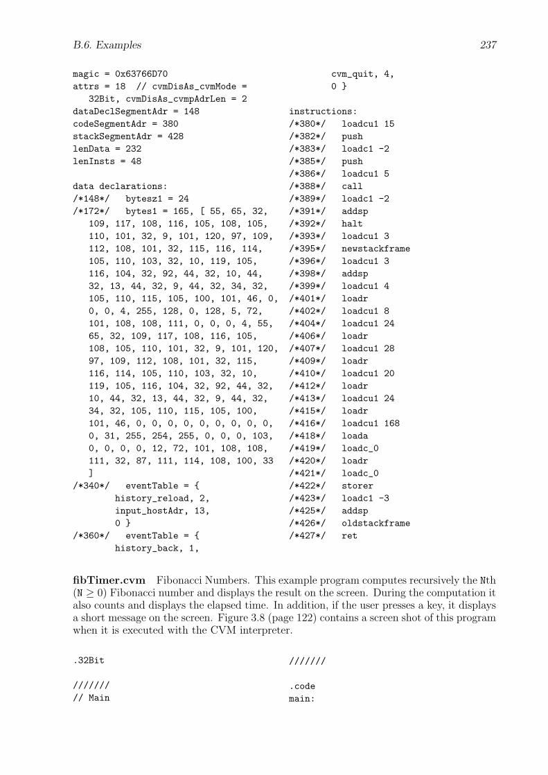
B.6. Examples 237
magic = 0x63766D70attrs = 18 // cvmDisAs_cvmMode =
32Bit, cvmDisAs_cvmpAdrLen = 2dataDeclSegmentAdr = 148codeSegmentAdr = 380stackSegmentAdr = 428lenData = 232lenInsts = 48
data declarations:/*148*/ bytesz1 = 24/*172*/ bytes1 = 165, [ 55, 65, 32,
109, 117, 108, 116, 105, 108, 105,110, 101, 32, 9, 101, 120, 97, 109,112, 108, 101, 32, 115, 116, 114,105, 110, 103, 32, 10, 119, 105,116, 104, 32, 92, 44, 32, 10, 44,32, 13, 44, 32, 9, 44, 32, 34, 32,105, 110, 115, 105, 100, 101, 46, 0,0, 0, 4, 255, 128, 0, 128, 5, 72,101, 108, 108, 111, 0, 0, 0, 4, 55,65, 32, 109, 117, 108, 116, 105,108, 105, 110, 101, 32, 9, 101, 120,97, 109, 112, 108, 101, 32, 115,116, 114, 105, 110, 103, 32, 10,119, 105, 116, 104, 32, 92, 44, 32,10, 44, 32, 13, 44, 32, 9, 44, 32,34, 32, 105, 110, 115, 105, 100,101, 46, 0, 0, 0, 0, 0, 0, 0, 0, 0,0, 31, 255, 254, 255, 0, 0, 0, 103,0, 0, 0, 0, 12, 72, 101, 108, 108,111, 32, 87, 111, 114, 108, 100, 33]
/*340*/ eventTable = {history_reload, 2,input_hostAdr, 13,0 }
/*360*/ eventTable = {history_back, 1,
cvm_quit, 4,0 }
instructions:/*380*/ loadcu1 15/*382*/ push/*383*/ loadc1 -2/*385*/ push/*386*/ loadcu1 5/*388*/ call/*389*/ loadc1 -2/*391*/ addsp/*392*/ halt/*393*/ loadcu1 3/*395*/ newstackframe/*396*/ loadcu1 3/*398*/ addsp/*399*/ loadcu1 4/*401*/ loadr/*402*/ loadcu1 8/*404*/ loadcu1 24/*406*/ loadr/*407*/ loadcu1 28/*409*/ loadr/*410*/ loadcu1 20/*412*/ loadr/*413*/ loadcu1 24/*415*/ loadr/*416*/ loadcu1 168/*418*/ loada/*419*/ loadc_0/*420*/ loadr/*421*/ loadc_0/*422*/ storer/*423*/ loadc1 -3/*425*/ addsp/*426*/ oldstackframe/*427*/ ret
fibTimer.cvm Fibonacci Numbers. This example program computes recursively the Nth(N ≥ 0) Fibonacci number and displays the result on the screen. During the computation italso counts and displays the elapsed time. In addition, if the user presses a key, it displaysa short message on the screen. Figure 3.8 (page 122) contains a screen shot of this programwhen it is executed with the CVM interpreter.
.32Bit
///////// Main
///////
.codemain:
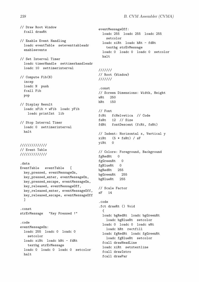
238 B. CVM Assembler (CVMA)
// Draw Root Windowfcall drawRt
// Enable Event Handlingloadc eventTable seteventtableadrenableevents
// Set Interval Timerloadc timerHandle settimerhandleadrloadc 10 settimerinterval
// Compute Fib(N)incsploadc N pushfcall Fibpop
// Display Resultloadc xFib + wFib loadc yFibloadc printInt lib
// Stop Interval Timerloadc 0 settimerintervalhalt
//////////////// Event Table//////////////
.dataEventTable eventTable [
key_pressed, eventMessageOn,key_pressed_enter, eventMessageOn,key_pressed_escape, eventMessageOn,key_released, eventMessageOff,key_released_enter, eventMessageOff,key_released_escape, eventMessageOff]
.conststrEvMessage "Key Pressed !"
.codeeventMessageOn:
loadc 255 loadc 0 loadc 0setcolor
loadc xiRt loadc hRt - fdRttextbg strEvMessage
loadc 0 loadc 0 loadc 0 setcolorhalt
eventMessageOff:loadc 255 loadc 255 loadc 255setcolor
loadc xiRt loadc hRt - fdRttextbg strEvMessage
loadc 0 loadc 0 loadc 0 setcolorhalt
///////// Root {Window}///////
.const// Screen Dimensions: Width, HeightwRt 250hRt 150
// FontfcRt fcHelvetica // CodefsRt 12 // SizefdRt fontDescent (fcRt, fsRt)
// Indent: Horizontal x, Vertical yxiRt (5 * fsRt) / sFyiRt 0
// Colors: Foreground, BackgroundfgRedRt 0fgGreenRt 0fgBlueRt 0bgRedRt 255bgGreenRt 255bgBlueRt 255
// Scale FactorsF 14
.code
.fct drawRt () Void{loadc bgRedRt loadc bgGreenRtloadc bgBlueRt setcolor
loadc 0 loadc 0 loadc wRtloadc hRt rectfill
loadc fgRedRt loadc fgGreenRtloadc fgBlueRt setcolor
fcall drawHeadLineloadc xiRt setxtextlinefcall drawIntrofcall drawPar

B.6. Examples 239
fcall drawFibfcall drawElapsereturn}
///////////// HeadLine {Text}///////////
.conststrHeadLine "Fibonacci"fcHeadLine fcHelveticaBoldItalicfsHeadLine 18fhHeadLine fontHeight (fcHeadLine,
fsHeadLine)xHeadLine xiRt +
(wIntro - wHeadLine) / 2yHeadLine yiRt + fhHeadLinewHeadLine textWidth (strHeadLine,
fcHeadLine, fsHeadLine)hHeadLine textHeight (strHeadLine,
fcHeadLine, fsHeadLine, 0)
.code
.fct drawHeadLine () Void{loadc fcHeadLine loadc fsHeadLinesetfont
loadc xHeadLine loadc yHeadLinetext strHeadLine
return}
////////// Intro {Text}////////
.conststrIntro textBreakLines (
"This CVM program computes "+ "recursively the Nth Fibonacci "+ "number. During the computation "+ "it counts the elapsed time.",fcRt, fsRt, wRt - 2 * xiRt)
xIntro xiRtyIntro yHeadLine + hHeadLinewIntro textWidth (strIntro, fcRt,
fsRt)hIntro textHeight (strIntro, fcRt,
fsRt, 0)
.code
.fct drawIntro () Void{loadc fcRt loadc fsRt setfontloadc yIntro textp strIntroreturn}
//////// Par {Text}//////
.conststrPar "N = "xPar xiRtyPar yIntro + hIntro +
(3 * fsRt) / sFwPar textWidth (strPar, fcRt,
fsRt)hPar textHeight (strPar, fcRt,
fsRt, 0)
.code
.fct drawPar () Void{loadc yPar textp strParloadc N loadc xPar + wParloadc yPar loadc printInt lib
return}
//////// Fib {Text}//////
.conststrFib "Fib(N) = "xFib xiRtyFib yPar + hParwFib textWidth (strFib, fcRt, fsRt)hFib textHeight (strFib, fcRt, fsRt,
0)
N 18
.code
.fct drawFib () Void

240 B. CVM Assembler (CVMA)
{loadc yFib textp strFibreturn}
/////////// Elapse {Text}/////////
.conststrElapse "Elapsed Time (1/100 s) = "xElapse xiRtyElapse yFib + hFib +
(3 * fsRt) / sFwElapse textWidth (strElapse, fcRt,
fsRt)hElapse textHeight (strElapse, fcRt,
fsRt, 0)
.code
.fct drawElapse () Void{loadc yElapse textp strElapsereturn}
/////////////////////// Fibonacci Function/////////////////////
.code
.fct Fib (Int n) Int{loadc 1 load n loadcr Fib_1 jlloadc 1 retstorereturn
Fib_1:incspload n dec pushfcall Fibincspload n loadc 2 sub pushfcall Fibpop pop add retstorereturn}
////////// Timer////////
.dataInt elapsedTime 0
.codetimerHandle:load elapsedTime incstore elapsedTime
load elapsedTimeloadc xElapse + wElapseloadc yElapse loadc printIntBglib
halt
During disassembling of the generated CVM packet file cvmp.bin, the disassembler cvmp2asciiproduces the following output:
magic = 0x63766D70attrs = 18 // cvmDisAs_cvmMode =
32Bit, cvmDisAs_cvmpAdrLen = 2dataDeclSegmentAdr = 0codeSegmentAdr = 56stackSegmentAdr = 476lenData = 56lenInsts = 418
data declarations:/* 0*/ bytesz1 = 4/* 4*/ eventTable = {
key_pressed, 91,key_pressed_enter, 91,
key_pressed_escape, 91,key_released, 120,key_released_enter, 120,key_released_escape, 120,0 }
instructions:/* 56*/ loadcu1 93/* 58*/ call/* 59*/ loadcu1 4/* 61*/ seteventtableadr/* 62*/ enableevents/* 63*/ loadcu2 459/* 66*/ settimerhandleadr
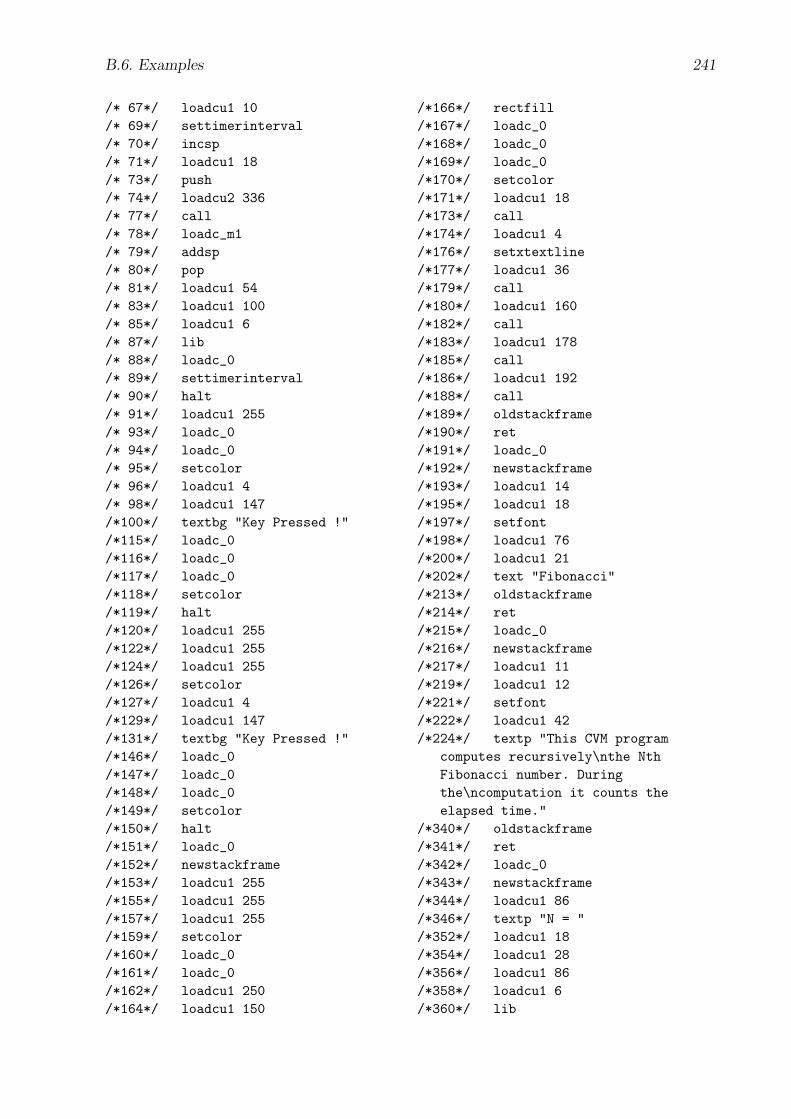
B.6. Examples 241
/* 67*/ loadcu1 10/* 69*/ settimerinterval/* 70*/ incsp/* 71*/ loadcu1 18/* 73*/ push/* 74*/ loadcu2 336/* 77*/ call/* 78*/ loadc_m1/* 79*/ addsp/* 80*/ pop/* 81*/ loadcu1 54/* 83*/ loadcu1 100/* 85*/ loadcu1 6/* 87*/ lib/* 88*/ loadc_0/* 89*/ settimerinterval/* 90*/ halt/* 91*/ loadcu1 255/* 93*/ loadc_0/* 94*/ loadc_0/* 95*/ setcolor/* 96*/ loadcu1 4/* 98*/ loadcu1 147/*100*/ textbg "Key Pressed !"/*115*/ loadc_0/*116*/ loadc_0/*117*/ loadc_0/*118*/ setcolor/*119*/ halt/*120*/ loadcu1 255/*122*/ loadcu1 255/*124*/ loadcu1 255/*126*/ setcolor/*127*/ loadcu1 4/*129*/ loadcu1 147/*131*/ textbg "Key Pressed !"/*146*/ loadc_0/*147*/ loadc_0/*148*/ loadc_0/*149*/ setcolor/*150*/ halt/*151*/ loadc_0/*152*/ newstackframe/*153*/ loadcu1 255/*155*/ loadcu1 255/*157*/ loadcu1 255/*159*/ setcolor/*160*/ loadc_0/*161*/ loadc_0/*162*/ loadcu1 250/*164*/ loadcu1 150
/*166*/ rectfill/*167*/ loadc_0/*168*/ loadc_0/*169*/ loadc_0/*170*/ setcolor/*171*/ loadcu1 18/*173*/ call/*174*/ loadcu1 4/*176*/ setxtextline/*177*/ loadcu1 36/*179*/ call/*180*/ loadcu1 160/*182*/ call/*183*/ loadcu1 178/*185*/ call/*186*/ loadcu1 192/*188*/ call/*189*/ oldstackframe/*190*/ ret/*191*/ loadc_0/*192*/ newstackframe/*193*/ loadcu1 14/*195*/ loadcu1 18/*197*/ setfont/*198*/ loadcu1 76/*200*/ loadcu1 21/*202*/ text "Fibonacci"/*213*/ oldstackframe/*214*/ ret/*215*/ loadc_0/*216*/ newstackframe/*217*/ loadcu1 11/*219*/ loadcu1 12/*221*/ setfont/*222*/ loadcu1 42/*224*/ textp "This CVM program
computes recursively\nthe NthFibonacci number. Duringthe\ncomputation it counts theelapsed time."
/*340*/ oldstackframe/*341*/ ret/*342*/ loadc_0/*343*/ newstackframe/*344*/ loadcu1 86/*346*/ textp "N = "/*352*/ loadcu1 18/*354*/ loadcu1 28/*356*/ loadcu1 86/*358*/ loadcu1 6/*360*/ lib
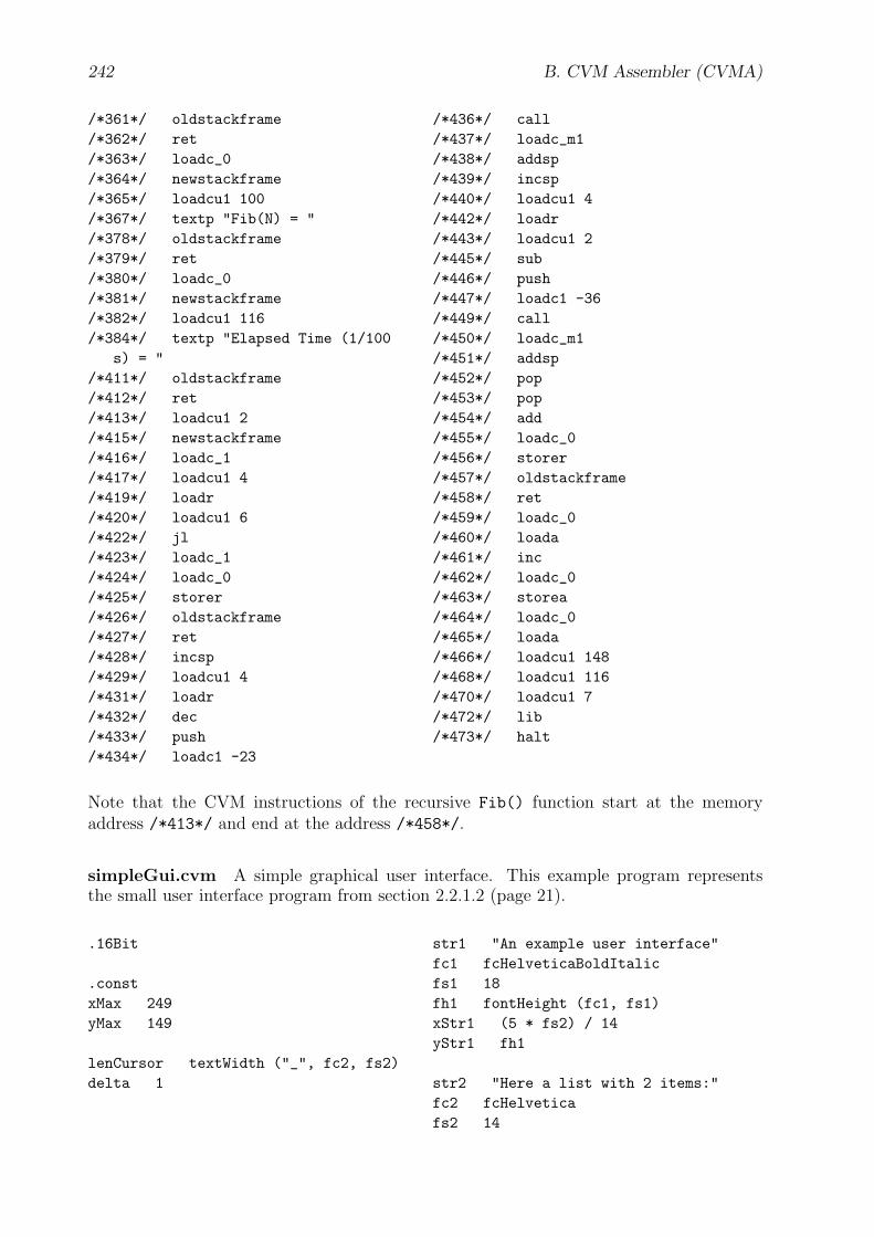
242 B. CVM Assembler (CVMA)
/*361*/ oldstackframe/*362*/ ret/*363*/ loadc_0/*364*/ newstackframe/*365*/ loadcu1 100/*367*/ textp "Fib(N) = "/*378*/ oldstackframe/*379*/ ret/*380*/ loadc_0/*381*/ newstackframe/*382*/ loadcu1 116/*384*/ textp "Elapsed Time (1/100
s) = "/*411*/ oldstackframe/*412*/ ret/*413*/ loadcu1 2/*415*/ newstackframe/*416*/ loadc_1/*417*/ loadcu1 4/*419*/ loadr/*420*/ loadcu1 6/*422*/ jl/*423*/ loadc_1/*424*/ loadc_0/*425*/ storer/*426*/ oldstackframe/*427*/ ret/*428*/ incsp/*429*/ loadcu1 4/*431*/ loadr/*432*/ dec/*433*/ push/*434*/ loadc1 -23
/*436*/ call/*437*/ loadc_m1/*438*/ addsp/*439*/ incsp/*440*/ loadcu1 4/*442*/ loadr/*443*/ loadcu1 2/*445*/ sub/*446*/ push/*447*/ loadc1 -36/*449*/ call/*450*/ loadc_m1/*451*/ addsp/*452*/ pop/*453*/ pop/*454*/ add/*455*/ loadc_0/*456*/ storer/*457*/ oldstackframe/*458*/ ret/*459*/ loadc_0/*460*/ loada/*461*/ inc/*462*/ loadc_0/*463*/ storea/*464*/ loadc_0/*465*/ loada/*466*/ loadcu1 148/*468*/ loadcu1 116/*470*/ loadcu1 7/*472*/ lib/*473*/ halt
Note that the CVM instructions of the recursive Fib() function start at the memoryaddress /*413*/ and end at the address /*458*/.
simpleGui.cvm A simple graphical user interface. This example program representsthe small user interface program from section 2.2.1.2 (page 21).
.16Bit
.constxMax 249yMax 149
lenCursor textWidth ("_", fc2, fs2)delta 1
str1 "An example user interface"fc1 fcHelveticaBoldItalicfs1 18fh1 fontHeight (fc1, fs1)xStr1 (5 * fs2) / 14yStr1 fh1
str2 "Here a list with 2 items:"fc2 fcHelveticafs2 14

B.6. Examples 243
fa2 fontAscent (fc2, fs2)fd2 fontDescent (fc2, fs2)fh2 fontHeight (fc2, fs2)yStr2 yStr1 + fh1
xDot xStr1 + (5 * fs2) / 14yDot yStr3 - (fontAscent (fc2, fs2)
+ dDot) / 2 + 1dDot (4 * fs2) / 14
str3 "First item"xStr3 xDot + (10 * fs2) / 14yStr3 yStr2 + fh2 + (3 * fs2) / 14
str4 "Second item"yStr4 yStr3 + fh2
str5 "A hyperlink:"yStr5 yStr4 + fh2 + (8 * fs2) / 14
str6 "http://www.w3c.org"xStr6 xStr1 + textWidth (str5, fc2,
fs2) + (15 * fs2) / 14
str7 "Finally a button:"yStr7 yStr5 + fh2 + (13 * fs2) / 14
str8 "Click me"xStr8 xStr1 + textWidth (str7, fc2,
fs2) + (15 * fs2) / 14
wHyperlink textWidth (str6, fc2, fs2)
xButton xStr8 - (4 * fs2) / 14yButton yStr7 - fontAscent (fc2, fs2)
+ 1 - (4 * fs2) / 14wButton textWidth (str8, fc2, fs2) +
(9 * fs2) / 14hButton fontAscent (fc2, fs2) + (9 *
fs2) / 14
.dataBytes cursorBgPixmap lenCursor * 4
// x-y position of cursorInt xPos (150 * fs2) / 14Int yPos (70 * fs2) / 14
// state of the hyperlinkInt visited 0
// state of the buttonInt currentlyPressed 0
// mixedInt x2 0
EventTable eventTable [key_pressed, keyPressed,key_pressed_enter, keyPressedEnter,key_released_enter, keyReleasedEnter ]
.codemain:loadcr paintUserInterface callloadcr paintCursor callloadc eventTable seteventtableadrenableeventshalt
// paint procedures
paintUserInterface:loadc fc1 loadc fs1 setfontloadc xStr1 loadc yStr1 text str1loadc fc2 loadc fs2 setfontloadc xStr1 loadc yStr2 text str2loadc xDot loadc yDot loadc dDotcirclefill
loadc xStr3 loadc yStr3 text str3loadc xDot loadc yDot + fh2loadc dDot circlefill
loadc xStr3 loadc yStr4 text str4loadc xStr1 loadc yStr5 text str5loadcr paintHyperlink callloadc xStr1 loadc yStr7 text str7loadcr paintButton callret
paintHyperlink:load visited loadc 0 loadcr isVisitedjne
loadc 0 loadc 0 loadc 255 setcolorloadcr paintHyperlink_1 jmp
isVisited:loadc 255 loadc 0 loadc 0 setcolor
paintHyperlink_1:loadc xStr6 loadc yStr5 text str6loadc xStr6 loadc yStr5 + 2loadc wHyperlink linehoriz
loadc 0 loadc 0 loadc 0 setcolorret

244 B. CVM Assembler (CVMA)
paintButton:load currentlyPressed loadc 0loadcr isCurrentlyPressed jne
loadc 0 loadc 255 loadc 0 setcolorloadcr paintButton_1 jmp
isCurrentlyPressed:loadc 255 loadc 0 loadc 0 setcolor
paintButton_1:loadc xButton loadc yButtonloadc wButton loadc hButtonrectfill
loadc 0 loadc 0 loadc 0 setcolorloadc xButton loadc yButtonloadc wButton loadc hButton rect
loadc xStr8 loadc yStr7 text str8ret
paintCursor:load xPos load yPos loadc lenCursorloadc 1loadc cursorBgPixmapscreen2mem
load xPos load yPos loadc lenCursorlinehoriz
ret
// event handling
keyPressed:loadep1 loadc XK_Leftloadcr keyPressedLeft je
loadep1 loadc XK_Uploadcr keyPressedUp je
loadep1 loadc XK_Downloadcr keyPressedDown je
loadep1 loadc XK_Rightloadcr keyPressedRight je
keyPressedIgnore:halt
keyPressedLeft:load xPos loadc delta sub loadc 0loadcr keyPressedIgnore jl
load xPos load yPos loadc lenCursorloadc 1 loadc cursorBgPixmapmem2screen
load xPos loadc delta substore xPos
loadcr paintCursor callhalt
keyPressedRight:loadc xMax load xPos
loadc lenCursor add decloadc delta addloadcr keyPressedIgnore jl
load xPos load yPos loadc lenCursorloadc 1 loadc cursorBgPixmapmem2screen
load xPos loadc delta addstore xPos
loadcr paintCursor callhalt
keyPressedUp:load yPos loadc delta sub loadc 0loadcr keyPressedIgnore jl
load xPos load yPos loadc lenCursorloadc 1loadc cursorBgPixmapmem2screen
load yPos loadc delta substore yPos
loadcr paintCursor callhalt
keyPressedDown:loadc yMax load yPos loadc deltaadd loadcr keyPressedIgnore jl
load xPos load yPos loadc lenCursorloadc 1loadc cursorBgPixmapmem2screen
loadc delta load yPos addstore yPos
loadcr paintCursor callhalt
keyPressedEnter:keyPressedEnterIfHyperlink:load xPos loadc xStr6loadcr keyPressedEnterIfButton jl
loadc xStr6 + wHyperlink - lenCursorload xPosloadcr keyPressedEnterIfButton jl
load yPos loadc yStr5 - fa2loadcr keyPressedEnterIfButton jl
loadc yStr5 + fd2 load yPosloadcr keyPressedEnterIfButton jl
keyPressedEnterHyperlink:loadc 1 store visitedload xPos load yPos loadc lenCursorloadc 1
loadc cursorBgPixmapmem2screen
loadcr paintHyperlink call
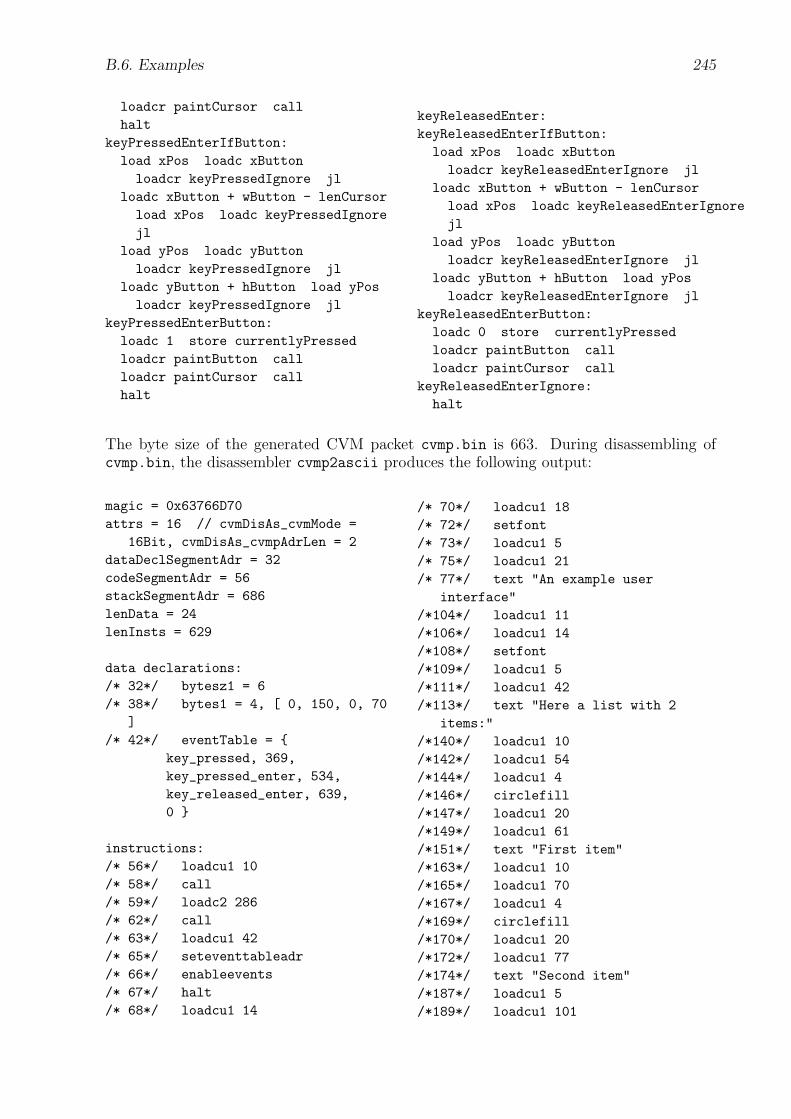
B.6. Examples 245
loadcr paintCursor callhalt
keyPressedEnterIfButton:load xPos loadc xButtonloadcr keyPressedIgnore jl
loadc xButton + wButton - lenCursorload xPos loadc keyPressedIgnorejl
load yPos loadc yButtonloadcr keyPressedIgnore jl
loadc yButton + hButton load yPosloadcr keyPressedIgnore jl
keyPressedEnterButton:loadc 1 store currentlyPressedloadcr paintButton callloadcr paintCursor callhalt
keyReleasedEnter:keyReleasedEnterIfButton:load xPos loadc xButtonloadcr keyReleasedEnterIgnore jl
loadc xButton + wButton - lenCursorload xPos loadc keyReleasedEnterIgnorejl
load yPos loadc yButtonloadcr keyReleasedEnterIgnore jl
loadc yButton + hButton load yPosloadcr keyReleasedEnterIgnore jl
keyReleasedEnterButton:loadc 0 store currentlyPressedloadcr paintButton callloadcr paintCursor call
keyReleasedEnterIgnore:halt
The byte size of the generated CVM packet cvmp.bin is 663. During disassembling ofcvmp.bin, the disassembler cvmp2ascii produces the following output:
magic = 0x63766D70attrs = 16 // cvmDisAs_cvmMode =
16Bit, cvmDisAs_cvmpAdrLen = 2dataDeclSegmentAdr = 32codeSegmentAdr = 56stackSegmentAdr = 686lenData = 24lenInsts = 629
data declarations:/* 32*/ bytesz1 = 6/* 38*/ bytes1 = 4, [ 0, 150, 0, 70
]/* 42*/ eventTable = {
key_pressed, 369,key_pressed_enter, 534,key_released_enter, 639,0 }
instructions:/* 56*/ loadcu1 10/* 58*/ call/* 59*/ loadc2 286/* 62*/ call/* 63*/ loadcu1 42/* 65*/ seteventtableadr/* 66*/ enableevents/* 67*/ halt/* 68*/ loadcu1 14
/* 70*/ loadcu1 18/* 72*/ setfont/* 73*/ loadcu1 5/* 75*/ loadcu1 21/* 77*/ text "An example user
interface"/*104*/ loadcu1 11/*106*/ loadcu1 14/*108*/ setfont/*109*/ loadcu1 5/*111*/ loadcu1 42/*113*/ text "Here a list with 2
items:"/*140*/ loadcu1 10/*142*/ loadcu1 54/*144*/ loadcu1 4/*146*/ circlefill/*147*/ loadcu1 20/*149*/ loadcu1 61/*151*/ text "First item"/*163*/ loadcu1 10/*165*/ loadcu1 70/*167*/ loadcu1 4/*169*/ circlefill/*170*/ loadcu1 20/*172*/ loadcu1 77/*174*/ text "Second item"/*187*/ loadcu1 5/*189*/ loadcu1 101
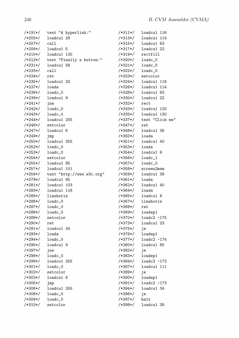
246 B. CVM Assembler (CVMA)
/*191*/ text "A hyperlink:"/*205*/ loadcu1 28/*207*/ call/*208*/ loadcu1 5/*210*/ loadcu1 130/*212*/ text "Finally a button:"/*231*/ loadcu1 58/*233*/ call/*234*/ ret/*235*/ loadcu1 32/*237*/ loada/*238*/ loadc_0/*239*/ loadcu1 9/*241*/ jne/*242*/ loadc_0/*243*/ loadc_0/*244*/ loadcu1 255/*246*/ setcolor/*247*/ loadcu1 6/*249*/ jmp/*250*/ loadcu1 255/*252*/ loadc_0/*253*/ loadc_0/*254*/ setcolor/*255*/ loadcu1 95/*257*/ loadcu1 101/*259*/ text "http://www.w3c.org"/*279*/ loadcu1 95/*281*/ loadcu1 103/*283*/ loadcu1 118/*285*/ linehoriz/*286*/ loadc_0/*287*/ loadc_0/*288*/ loadc_0/*289*/ setcolor/*290*/ ret/*291*/ loadcu1 34/*293*/ loada/*294*/ loadc_0/*295*/ loadcu1 9/*297*/ jne/*298*/ loadc_0/*299*/ loadcu1 255/*301*/ loadc_0/*302*/ setcolor/*303*/ loadcu1 6/*305*/ jmp/*306*/ loadcu1 255/*308*/ loadc_0/*309*/ loadc_0/*310*/ setcolor
/*311*/ loadcu1 116/*313*/ loadcu1 114/*315*/ loadcu1 63/*317*/ loadcu1 22/*319*/ rectfill/*320*/ loadc_0/*321*/ loadc_0/*322*/ loadc_0/*323*/ setcolor/*324*/ loadcu1 116/*326*/ loadcu1 114/*328*/ loadcu1 63/*330*/ loadcu1 22/*332*/ rect/*333*/ loadcu1 120/*335*/ loadcu1 130/*337*/ text "Click me"/*347*/ ret/*348*/ loadcu1 38/*350*/ loada/*351*/ loadcu1 40/*353*/ loada/*354*/ loadcu1 8/*356*/ loadc_1/*357*/ loadc_0/*358*/ screen2mem/*359*/ loadcu1 38/*361*/ loada/*362*/ loadcu1 40/*364*/ loada/*365*/ loadcu1 8/*367*/ linehoriz/*368*/ ret/*369*/ loadep1/*370*/ loadc2 -175/*373*/ loadcu1 23/*375*/ je/*376*/ loadep1/*377*/ loadc2 -174/*380*/ loadcu1 85/*382*/ je/*383*/ loadep1/*384*/ loadc2 -172/*387*/ loadcu1 111/*389*/ je/*390*/ loadep1/*391*/ loadc2 -173/*394*/ loadcu1 34/*396*/ je/*397*/ halt/*398*/ loadcu1 38
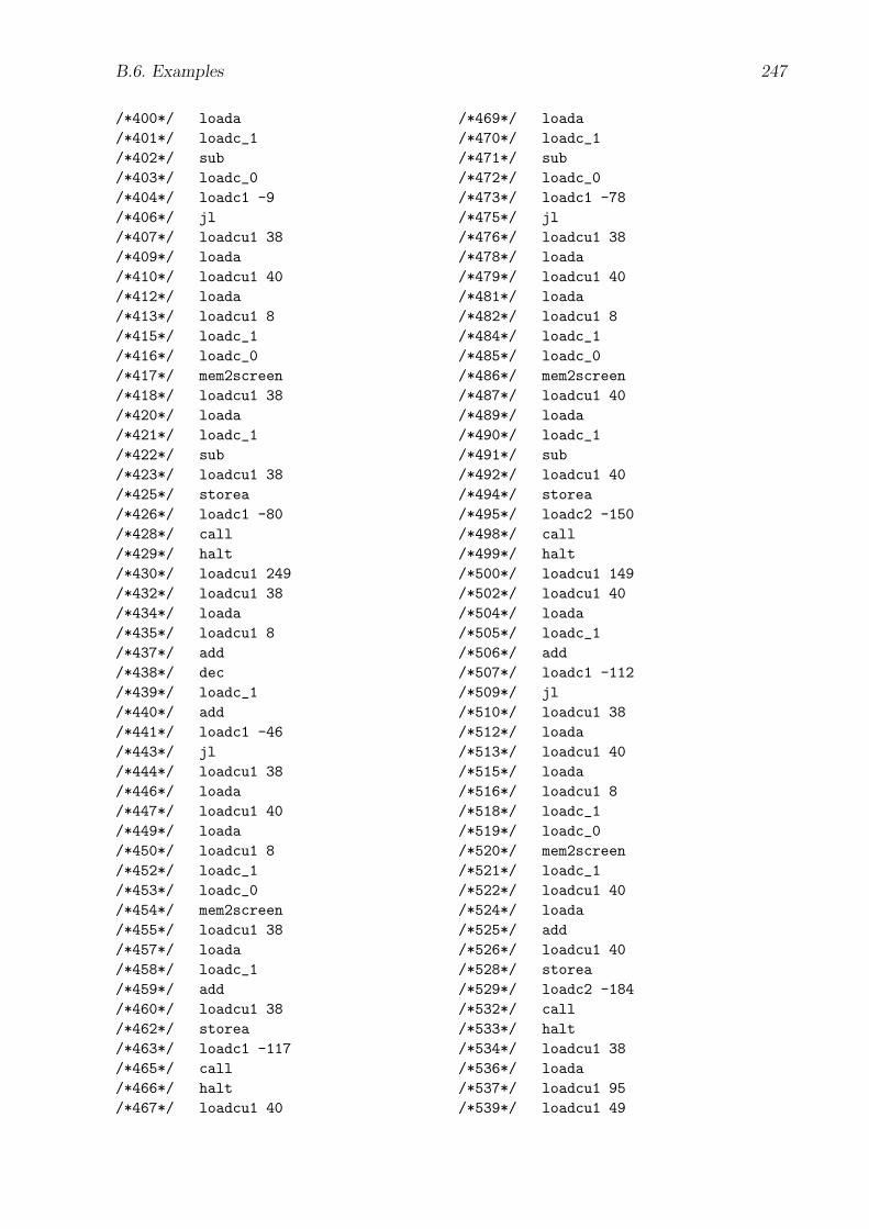
B.6. Examples 247
/*400*/ loada/*401*/ loadc_1/*402*/ sub/*403*/ loadc_0/*404*/ loadc1 -9/*406*/ jl/*407*/ loadcu1 38/*409*/ loada/*410*/ loadcu1 40/*412*/ loada/*413*/ loadcu1 8/*415*/ loadc_1/*416*/ loadc_0/*417*/ mem2screen/*418*/ loadcu1 38/*420*/ loada/*421*/ loadc_1/*422*/ sub/*423*/ loadcu1 38/*425*/ storea/*426*/ loadc1 -80/*428*/ call/*429*/ halt/*430*/ loadcu1 249/*432*/ loadcu1 38/*434*/ loada/*435*/ loadcu1 8/*437*/ add/*438*/ dec/*439*/ loadc_1/*440*/ add/*441*/ loadc1 -46/*443*/ jl/*444*/ loadcu1 38/*446*/ loada/*447*/ loadcu1 40/*449*/ loada/*450*/ loadcu1 8/*452*/ loadc_1/*453*/ loadc_0/*454*/ mem2screen/*455*/ loadcu1 38/*457*/ loada/*458*/ loadc_1/*459*/ add/*460*/ loadcu1 38/*462*/ storea/*463*/ loadc1 -117/*465*/ call/*466*/ halt/*467*/ loadcu1 40
/*469*/ loada/*470*/ loadc_1/*471*/ sub/*472*/ loadc_0/*473*/ loadc1 -78/*475*/ jl/*476*/ loadcu1 38/*478*/ loada/*479*/ loadcu1 40/*481*/ loada/*482*/ loadcu1 8/*484*/ loadc_1/*485*/ loadc_0/*486*/ mem2screen/*487*/ loadcu1 40/*489*/ loada/*490*/ loadc_1/*491*/ sub/*492*/ loadcu1 40/*494*/ storea/*495*/ loadc2 -150/*498*/ call/*499*/ halt/*500*/ loadcu1 149/*502*/ loadcu1 40/*504*/ loada/*505*/ loadc_1/*506*/ add/*507*/ loadc1 -112/*509*/ jl/*510*/ loadcu1 38/*512*/ loada/*513*/ loadcu1 40/*515*/ loada/*516*/ loadcu1 8/*518*/ loadc_1/*519*/ loadc_0/*520*/ mem2screen/*521*/ loadc_1/*522*/ loadcu1 40/*524*/ loada/*525*/ add/*526*/ loadcu1 40/*528*/ storea/*529*/ loadc2 -184/*532*/ call/*533*/ halt/*534*/ loadcu1 38/*536*/ loada/*537*/ loadcu1 95/*539*/ loadcu1 49
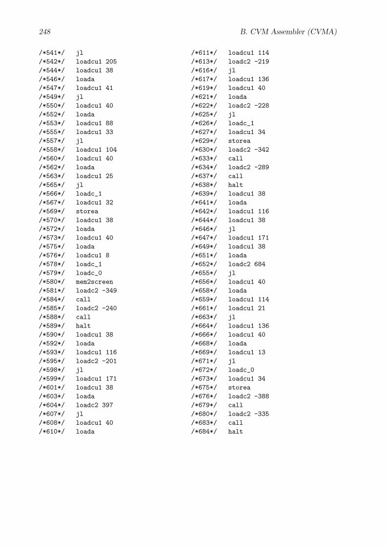
248 B. CVM Assembler (CVMA)
/*541*/ jl/*542*/ loadcu1 205/*544*/ loadcu1 38/*546*/ loada/*547*/ loadcu1 41/*549*/ jl/*550*/ loadcu1 40/*552*/ loada/*553*/ loadcu1 88/*555*/ loadcu1 33/*557*/ jl/*558*/ loadcu1 104/*560*/ loadcu1 40/*562*/ loada/*563*/ loadcu1 25/*565*/ jl/*566*/ loadc_1/*567*/ loadcu1 32/*569*/ storea/*570*/ loadcu1 38/*572*/ loada/*573*/ loadcu1 40/*575*/ loada/*576*/ loadcu1 8/*578*/ loadc_1/*579*/ loadc_0/*580*/ mem2screen/*581*/ loadc2 -349/*584*/ call/*585*/ loadc2 -240/*588*/ call/*589*/ halt/*590*/ loadcu1 38/*592*/ loada/*593*/ loadcu1 116/*595*/ loadc2 -201/*598*/ jl/*599*/ loadcu1 171/*601*/ loadcu1 38/*603*/ loada/*604*/ loadc2 397/*607*/ jl/*608*/ loadcu1 40/*610*/ loada
/*611*/ loadcu1 114/*613*/ loadc2 -219/*616*/ jl/*617*/ loadcu1 136/*619*/ loadcu1 40/*621*/ loada/*622*/ loadc2 -228/*625*/ jl/*626*/ loadc_1/*627*/ loadcu1 34/*629*/ storea/*630*/ loadc2 -342/*633*/ call/*634*/ loadc2 -289/*637*/ call/*638*/ halt/*639*/ loadcu1 38/*641*/ loada/*642*/ loadcu1 116/*644*/ loadcu1 38/*646*/ jl/*647*/ loadcu1 171/*649*/ loadcu1 38/*651*/ loada/*652*/ loadc2 684/*655*/ jl/*656*/ loadcu1 40/*658*/ loada/*659*/ loadcu1 114/*661*/ loadcu1 21/*663*/ jl/*664*/ loadcu1 136/*666*/ loadcu1 40/*668*/ loada/*669*/ loadcu1 13/*671*/ jl/*672*/ loadc_0/*673*/ loadcu1 34/*675*/ storea/*676*/ loadc2 -388/*679*/ call/*680*/ loadc2 -335/*683*/ call/*684*/ halt

Appendix C
CVMUI Library (CVMUI Lib)
The CVMUI library contains constant and function definitions that are imported by CVM-UI programs. Note that the CVMUI libraries that are presented in this thesis serve only asan example to demonstrate the concept. Additional libraries may be defined in the future.
C.1 libMisc.cvm
This CVMUI library contains basic definitions about strings, etc.
libMisc emptyProc This “trivial” procedure does nothing, but returns immediately.
.codelibMisc_emptyProc:
ret
libMisc bytesCp This function copies len bytes from the memory address adrSrc toadrTgt.
.code
.fct libMisc_bytesCp(Int adrTgt, Int adrSrc, Int len){
libMisc_bytesCp_1:load lenloadc 0loadcr libMisc_bytesCp_jle
load adrSrc
load len decrdup store lenaload1load adrTgtload lenastore1
loadcr libMisc_bytesCp_1 jmplibMisc_bytesCp_:return}
libMisc strCp This function copies the CVM string at the memory address adrSrc tothe memory address adrTgt. Note that for the target string always the longer String formatis chosen. Refer to section 3.1.1 (page 33) for more information on the CVM string formats.
249

250 C. CVMUI Library (CVMUI Lib)
.code// strTgt = [0#1, len#2, ...]
.fct libMisc_strCp(Int adrTgt, Int adrSrc){loadc 0load adrTgtloadc 0astore1
load adrTgt inc store adrTgtload adrSrc loadc 0 aload1rdupload adrSrc inc store adrSrcloadc 0loadcr libMisc_strCp_le255
jnelibMisc_strCp_g255:rskipload adrSrc loadc 0 aload2load adrSrc loadc 2 addstore adrSrc
libMisc_strCp_le255:rdupload adrTgt loadc 0 astore2load adrTgt loadc 2 add pushload adrSrc pushpushfcall libMisc_bytesCp
return}
libMisc strAppChar This function appends the character char to the CVM stringat the memory address adrStr, if the string has less then maxLen characters before theoperation. Note that the String format of the string must be the longer one. Refer tosection 3.1.1 (page 33) for more information on the CVM string formats.
.code// adrStr = [0#1, len#2, ...]
.fct libMisc_strAppChar(Int adrStr, Int maxLen, Int char){Int strLenincsp load adrStr pushfcall libMisc_strLenpop store strLen
load maxLenload strLenloadcr libMisc_strAppChar_1
jleload charload adrStrloadc 3 addload strLen addloadc 0 astore1
load adrStr pushload strLen inc pushfcall libMisc_strLenSet
libMisc_strAppChar_1:return}
libMisc strLen This function returns the length of the CVM string at the memoryaddress adrStr, which is the value of the length item in the tuple structure String, butnot the byte length of the whole tuple structure. Refer to section 3.1.1 (page 33) for moreinformation on the CVM string formats.
.code
.fct libMisc_strLen (Int adrStr) Int{load adrStr loadc 0 aload1 rduploadc 0 loadcr libMisc_strLen_1 jne
libMisc_strLen_g255:
rskipload adrStr inc loadc 0 aload2
libMisc_strLen_1:retstorereturn}
libMisc strLenSet This function writes the value of strLen into the length item ofthe CVM string at the memory address adrStr. Note that the String format of the string

C.2. libGui.cvm 251
must be the longer one. Refer to section 3.1.1 (page 33) for more information on the CVMstring formats.
.code// [0, strLen#2, ...]
.fct libMisc_strLenSet(Int adrStr, Int strLen){loadc 0load adrStrloadc 0
astore1load strLenload adrStr incloadc 0astore2
return}
C.2 libGui.cvm
This CVMUI library contains definitions for all user interface components.
Property Offsets of User Interface Components The property values of the userinterface components are stored in memory in appropriate tuple structures. The followingconstants are used to address these property values relatively within the respective tuplestructure:
.const
//////// Btn {Button}, Hlk {Hyperlink},// Ixt {Text Box}//////
libGui_etOfs 0libGui_xOfs 1 * _cillibGui_yOfs 2 * _cillibGui_wOfs 3 * _cillibGui_hOfs 4 * _cillibGui_fgRedOfs 5 * _cillibGui_fgGreenOfs 6 * _cillibGui_fgBlueOfs 7 * _cillibGui_bgRedOfs 8 * _cillibGui_bgGreenOfs 9 * _cillibGui_bgBlueOfs 10 * _cil
libGui_fcOfs 11 * _cillibGui_fsOfs 12 * _cillibGui_adrStrOfs 13 * _cillibGui_xStrOfs 14 * _cillibGui_yStrOfs 15 * _cil
//////// Btn {Button}//////
libGui_img 16 * _cillibGui_imgStyle 17 * _cil
//////// Hlk {Hyperlink}//////
libGui_hostAdrOfs 16 * _cillibGui_serviceNoOfs 17 * _cil
//////// Ixt {Text Box}//////
libGui_wStrOfs 16 * _cillibGui_hStrOfs 17 * _cillibGui_yaStrOfs 18 * _cillibGui_strLenMaxOfs 19 * _cillibGui_wCharOfs 20 * _cillibGui_strPosOfs 21 * _cil
cil (“CVM integer length”) is an integer constant and must be defined in the main CVM-As program that imports these constant definitions. It is equal to the value of cvmIntLen.

252 C. CVMUI Library (CVMUI Lib)
Refer to section 3.1.2 (page 33) for more information on cvmIntLen.
The tuple structures for the different user interface component types are defined as follows:
• Page: { Int et; }Refer to section 3.1.1 (page 33) for the CVM data type Int. Refer to <pagepageNoReq,j
.id>_<j>_prp in the CVMA code template in section 5.5.2 (pages 170 ff.) for theproperty value et.
• Button (Btn):
{ Int et,x, y, w, h,fgr, fgb, fgg,bgr, bgb, bgg,fc, fs,str, xStr, yStr,img, imgStyle; }
Refer to <pagepageNoReq,j .id>_<j>_<btn.id>_prp in the CVMA code template insection 5.5.7 (pages 192 ff.) for the property values.
• Hyperlink (Hlk):
{ Int et,x, y, w, h,fgr, fgb, fgg,bgr, bgb, bgg,fc, fs,str, xStr, yStr,hostAdr, serviceNo; }
Refer to <hlk .id>_prp in the CVMA code template in section 5.5.6 (pages 187 ff.)for the property values.
• Text Box (Ixt):
{ Int et,x, y, w, h,fgr, fgb, fgg,bgr, bgb, bgg,fc, fs,str, xStr, yStr,wStr, hStr, yaStr,strLenMax, wChar, strPos; }
Refer to <ixt .id>_prp in the CVMA code template in section 5.5.5 (page 182) forthe property values.
• Text (Txt): So far, Txt user interface components have no property values.
libGui linehorizDash This function draws a horizontal dashed line from start point (x,y) to end point (x + w − 1, y).

C.2. libGui.cvm 253
.code
.fct libGui_linehorizDash(Int x, Int y, Int w){
libGui_linehorizDash_1:load w loadc 0loadcr libGui_linehorizDash_2 jle
load x load y loadc 1
linehorizload x inc inc store xload w dec dec store wloadcr libGui_linehorizDash_1 jmp
libGui_linehorizDash_2:return}
libGui linevertDash This function draws a vertical dashed line from start point (x, y)to end point (x, y + h − 1).
.code
.fct libGui_linevertDash(Int x, Int y, Int h){
libGui_linevertDash_1:load h loadc 0loadcr libGui_linevertDash_2 jle
load x load y loadc 1
linevertload y inc inc store yload h dec dec store hloadcr libGui_linevertDash_1 jmp
libGui_linevertDash_2:return}
libGui rectDash This function draws a dashed rectangle with the upper-left corner at(x, y) and the lower-right corner at (x + w − 1, y + h − 1).
.constlibGui_rectCornerDash 1
.code
.fct libGui_rectDash(Int x, Int y, Int w, Int h){Int x1Int y1Int w1Int h1load xloadc libGui_rectCornerDash addstore x1
load yloadc libGui_rectCornerDash addstore y1
load wloadc 2 * libGui_rectCornerDashsub store w1
load hloadc 2 * libGui_rectCornerDashsub store h1
load x1 pushload y pushload w1 pushfcall libGui_linehorizDash
load x pushload y1 pushload h1 pushfcall libGui_linevertDash
load x1 pushload yload hadd dec push
load w1 pushfcall libGui_linehorizDash
load xload wadd dec push
load y1 pushload h1 pushfcall libGui_linevertDash
return}
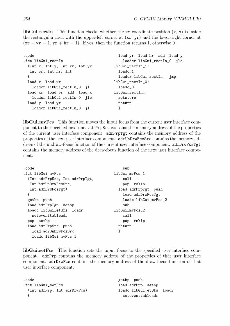
254 C. CVMUI Library (CVMUI Lib)
libGui rectIn This function checks whether the xy coordinate position (x, y) is insidethe rectangular area with the upper-left corner at (xr, yr) and the lower-right corner at(xr + wr − 1, yr + hr − 1). If yes, then the function returns 1, otherwise 0.
.code
.fct libGui_rectIn(Int x, Int y, Int xr, Int yr,Int wr, Int hr) Int{load x load xrloadcr libGui_rectIn_0 jl
load xr load wr add load xloadcr libGui_rectIn_0 jle
load y load yrloadcr libGui_rectIn_0 jl
load yr load hr add load yloadcr libGui_rectIn_0 jle
libGui_rectIn_1:loadc_1loadcr libGui_rectIn_ jmp
libGui_rectIn_0:loadc_0
libGui_rectIn_:retstorereturn}
libGui mvFcs This function moves the input focus from the current user interface com-ponent to the specified next one. adrPrpSrc contains the memory address of the propertiesof the current user interface component. adrPrpTgt contains the memory address of theproperties of the next user interface component. adrUnDrwFcsSrc contains the memory ad-dress of the undraw-focus function of the current user interface component. adrDrwFcsTgtcontains the memory address of the draw-focus function of the next user interface compo-nent.
.code
.fct libGui_mvFcs(Int adrPrpSrc, Int adrPrpTgt,Int adrUnDrwFcsSrc,Int adrDrwFcsTgt){getbp pushload adrPrpTgt setbploadc libGui_etOfs loadrseteventtableadr
pop setbpload adrPrpSrc pushload adrUnDrwFcsSrcloadc libGui_mvFcs_1
sublibGui_mvFcs_1:
callpop rskip
load adrPrpTgt pushload adrDrwFcsTgtloadc libGui_mvFcs_2sub
libGui_mvFcs_2:callpop rskip
return}
libGui setFcs This function sets the input focus to the specified user interface com-ponent. adrPrp contains the memory address of the properties of that user interfacecomponent. adrDrwFcs contains the memory address of the draw-focus function of thatuser interface component.
.code
.fct libGui_setFcs(Int adrPrp, Int adrDrwFcs){
getbp pushload adrPrp setbploadc libGui_etOfs loadrseteventtableadr

C.3. libGui3D.cvm 255
pop setbpload adrPrp pushload adrDrwFcsloadc libGui_setFcs_1sub
libGui_setFcs_1:callpop rskip
return}
C.3 libGui3D.cvm
This CVMUI library contains definitions for all user interface components with a 3D look.
Constants
.constlibGui3D_shadeDark 40
libGui3D_shadeBright 50libGui3D_shadeNorm 100
libGui3D colorShadeDark This function returns on the register stack the RGB valuesof the darker shadow color from the color that is given by the RGB values red, green, andblue. The darker shadow color is used together with the brighter shadow color to providea 3D look for the user interface components.
.code
.fct libGui3D_colorShadeDark(Int red, Int green, Int blue){load redloadc libGui3D_shadeNorm -
libGui3D_shadeDarkmul loadc libGui3D_shadeNorm div
load green
loadc libGui3D_shadeNorm -libGui3D_shadeDark
mul loadc libGui3D_shadeNorm divload blueloadc libGui3D_shadeNorm -
libGui3D_shadeDarkmul loadc libGui3D_shadeNorm div
return}
libGui3D colorShadeBright This function returns on the register stack the RGB val-ues of the brighter shadow color from the color that is given by the RGB values red,green, and blue. The brighter shadow color is used together with the darker shadow colorto provide a 3D look for the user interface components.
.code
.fct libGui3D_colorShadeBright(Int red, Int green, Int blue){load redloadc 255 load red subloadc libGui3D_shadeBright mulloadc libGui3D_shadeNorm divadd
load greenloadc 255 load green sub
loadc libGui3D_shadeBright mulloadc libGui3D_shadeNorm divadd
load blueloadc 255 load blue subloadc libGui3D_shadeBright mulloadc libGui3D_shadeNorm divadd
return}

256 C. CVMUI Library (CVMUI Lib)
C.4 libGuiTxtSmp.cvm
This CVMUI library contains definitions for all Txt user interface components with a“simple” (Smp) look.
Constants The ..._dx and ..._dy constants define the horizontal and vertical space be-tween the borders of the user interface component and its containing text.
.constlibGuiTxtSmp_dx 0libGuiTxtSmp_dy 0
libGuiTxtSmp_dw 2 * libGuiTxtSmp_dxlibGuiTxtSmp_dh 2 * libGuiTxtSmp_dy
C.5 libGuiTxt3D.cvm
This CVMUI library contains definitions for all Txt user interface components with a 3D
look.
Constants The ..._dx and ..._dy constants define the horizontal and vertical space be-tween the borders of the user interface component and its containing text.
.constlibGuiTxt3D_dx 0libGuiTxt3D_dy 0
libGuiTxt3D_dw 2 * libGuiTxt3D_dxlibGuiTxt3D_dh 2 * libGuiTxt3D_dy
C.6 libGuiTxpSmp.cvm
This CVMUI library contains definitions for all Txp user interface components with a“simple” (Smp) look.
Constants The ..._dx and ..._dy constants define the horizontal and vertical space be-tween the borders of the user interface component and its containing text.
.constlibGuiTxpSmp_dx 0libGuiTxpSmp_dy 0
libGuiTxpSmp_dw 2 * libGuiTxpSmp_dxlibGuiTxpSmp_dh 2 * libGuiTxpSmp_dy
C.7 libGuiTxp3D.cvm
This CVMUI library contains definitions for all Txp user interface components with a 3D
look.
Constants The ..._dx and ..._dy constants define the horizontal and vertical space be-tween the borders of the user interface component and its containing text.

C.8. libGuiHlk.cvm 257
.constlibGuiTxp3D_dx 0libGuiTxp3D_dy 0
libGuiTxp3D_dw 2 * libGuiTxp3D_dxlibGuiTxp3D_dh 2 * libGuiTxp3D_dy
C.8 libGuiHlk.cvm
This CVMUI library contains definitions for all Hlk user interface components.
libGuiHlk kp This function defines the implicit event behavior of an Hlk user interfacecomponent when a key pressed event occurs. adrPrp contains the memory address of theproperties of that user interface component. Refer to the sections 3.1.6 (pages 45 ff.) and5.1.1 (page 140) for more information on CVM events and AUI events.
.code
.fct libGuiHlk_kp (Int adrPrp){loadep1loadc XK_spaceloadcr libGuiHlk_kp_dwnje
returnlibGuiHlk_kp_dwn:load adrPrp pushfcall libGuiHlk_dwnreturn}
libGuiHlk dwn This function defines the implicit event behavior of an Hlk user interfacecomponent after it has been activated by the user of the CVM. adrPrp contains the memoryaddress of the properties of that user interface component.
.code
.fct libGuiHlk_dwn (Int adrPrp){load adrPrp setbpsidzeroloadc libGui_hostAdrOfs loadr
loadc libGui_serviceNoOfs loadrloadc 0rcv
return}
C.9 libGuiHlkSmp.cvm
This CVMUI library contains definitions for all Hlk user interface components with a“simple” (Smp) look.
Constants The ..._dx and ..._dy constants define the horizontal and vertical space be-tween the borders of the user interface component and its containing text.
.constlibGuiHlkSmp_dx 0libGuiHlkSmp_dy 0
libGuiHlkSmp_dw 2 * libGuiHlkSmp_dxlibGuiHlkSmp_dh 2 * libGuiHlkSmp_dy
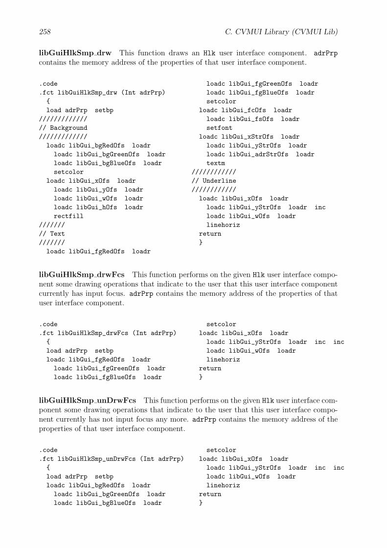
258 C. CVMUI Library (CVMUI Lib)
libGuiHlkSmp drw This function draws an Hlk user interface component. adrPrp
contains the memory address of the properties of that user interface component.
.code
.fct libGuiHlkSmp_drw (Int adrPrp){load adrPrp setbp
/////////////// Background/////////////
loadc libGui_bgRedOfs loadrloadc libGui_bgGreenOfs loadrloadc libGui_bgBlueOfs loadrsetcolor
loadc libGui_xOfs loadrloadc libGui_yOfs loadrloadc libGui_wOfs loadrloadc libGui_hOfs loadrrectfill
///////// Text///////loadc libGui_fgRedOfs loadr
loadc libGui_fgGreenOfs loadrloadc libGui_fgBlueOfs loadrsetcolor
loadc libGui_fcOfs loadrloadc libGui_fsOfs loadrsetfont
loadc libGui_xStrOfs loadrloadc libGui_yStrOfs loadrloadc libGui_adrStrOfs loadrtextm
////////////// Underline////////////loadc libGui_xOfs loadrloadc libGui_yStrOfs loadr incloadc libGui_wOfs loadrlinehoriz
return}
libGuiHlkSmp drwFcs This function performs on the given Hlk user interface compo-nent some drawing operations that indicate to the user that this user interface componentcurrently has input focus. adrPrp contains the memory address of the properties of thatuser interface component.
.code
.fct libGuiHlkSmp_drwFcs (Int adrPrp){load adrPrp setbploadc libGui_fgRedOfs loadrloadc libGui_fgGreenOfs loadrloadc libGui_fgBlueOfs loadr
setcolorloadc libGui_xOfs loadrloadc libGui_yStrOfs loadr inc incloadc libGui_wOfs loadrlinehoriz
return}
libGuiHlkSmp unDrwFcs This function performs on the given Hlk user interface com-ponent some drawing operations that indicate to the user that this user interface compo-nent currently has not input focus any more. adrPrp contains the memory address of theproperties of that user interface component.
.code
.fct libGuiHlkSmp_unDrwFcs (Int adrPrp){load adrPrp setbploadc libGui_bgRedOfs loadrloadc libGui_bgGreenOfs loadrloadc libGui_bgBlueOfs loadr
setcolorloadc libGui_xOfs loadrloadc libGui_yStrOfs loadr inc incloadc libGui_wOfs loadrlinehoriz
return}
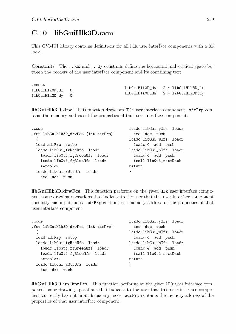
C.10. libGuiHlk3D.cvm 259
C.10 libGuiHlk3D.cvm
This CVMUI library contains definitions for all Hlk user interface components with a 3D
look.
Constants The ..._dx and ..._dy constants define the horizontal and vertical space be-tween the borders of the user interface component and its containing text.
.constlibGuiHlk3D_dx 0libGuiHlk3D_dy 0
libGuiHlk3D_dw 2 * libGuiHlk3D_dxlibGuiHlk3D_dh 2 * libGuiHlk3D_dy
libGuiHlk3D drw This function draws an Hlk user interface component. adrPrp con-tains the memory address of the properties of that user interface component.
.code
.fct libGuiHlk3D_drwFcs (Int adrPrp){load adrPrp setbploadc libGui_fgRedOfs loadrloadc libGui_fgGreenOfs loadrloadc libGui_fgBlueOfs loadrsetcolor
loadc libGui_xStrOfs loadrdec dec push
loadc libGui_yOfs loadrdec dec push
loadc libGui_wOfs loadrloadc 4 add push
loadc libGui_hOfs loadrloadc 4 add pushfcall libGui_rectDash
return}
libGuiHlk3D drwFcs This function performs on the given Hlk user interface compo-nent some drawing operations that indicate to the user that this user interface componentcurrently has input focus. adrPrp contains the memory address of the properties of thatuser interface component.
.code
.fct libGuiHlk3D_drwFcs (Int adrPrp){load adrPrp setbploadc libGui_fgRedOfs loadrloadc libGui_fgGreenOfs loadrloadc libGui_fgBlueOfs loadrsetcolor
loadc libGui_xStrOfs loadrdec dec push
loadc libGui_yOfs loadrdec dec push
loadc libGui_wOfs loadrloadc 4 add push
loadc libGui_hOfs loadrloadc 4 add pushfcall libGui_rectDash
return}
libGuiHlk3D unDrwFcs This function performs on the given Hlk user interface com-ponent some drawing operations that indicate to the user that this user interface compo-nent currently has not input focus any more. adrPrp contains the memory address of theproperties of that user interface component.

260 C. CVMUI Library (CVMUI Lib)
.code
.fct libGuiHlk3D_unDrwFcs (Int adrPrp){load adrPrp setbploadc libGui_bgRedOfs loadrloadc libGui_bgGreenOfs loadrloadc libGui_bgBlueOfs loadrsetcolor
loadc libGui_xStrOfs loadrdec dec push
loadc libGui_yOfs loadrdec dec push
loadc libGui_wOfs loadrloadc 4 add push
loadc libGui_hOfs loadrloadc 4 add pushfcall libGui_rectDash
return}
C.11 libGuiIxt.cvm
This CVMUI library contains definitions for all Ixt user interface components.
libGuiIxt drwTxt This function draws the text of an Ixt user interface component.adrPrp contains the memory address of the properties of that user interface component.The str property contains the memory address of the text.
.code
.fct libGuiIxt_drwTxt (Int adrPrp){load adrPrp setbploadc libGui_fcOfs loadrloadc libGui_fsOfs loadrsetfont
loadc libGui_fgRedOfs loadrloadc libGui_fgGreenOfs loadrloadc libGui_fgBlueOfs loadrsetcolor
loadc libGui_bgRedOfs loadrloadc libGui_bgGreenOfs loadrloadc libGui_bgBlueOfs loadrsetbgcolor
loadc libGui_xStrOfs loadrloadc libGui_yaStrOfs loadr
loadc libGui_wStrOfs loadrloadc libGui_hStrOfs loadrsetclip
loadc libGui_xStrOfs loadrloadc libGui_strPosOfs loadradd
loadc libGui_yStrOfs loadrloadc libGui_adrStrOfs loadrtextmbg
loadc 0loadc 0loadc _cvmScreenWidthloadc _cvmScreenHeightsetclip
return}
libGuiIxt drwCr This function draws the text cursor of an Ixt user interface compo-nent with its foreground color. adrPrp contains the memory address of the properties ofthat user interface component.
.code
.fct libGuiIxt_drwCr (Int adrPrp){getbp pushload adrPrp setbploadc libGui_fgRedOfs loadrloadc libGui_fgGreenOfs loadr
loadc libGui_fgBlueOfs loadrsetcolor
pop setbpload adrPrp pushfcall libGuiIxt_drwCr_1
return}
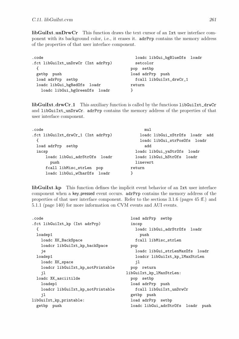
C.11. libGuiIxt.cvm 261
libGuiIxt unDrwCr This function draws the text cursor of an Ixt user interface com-ponent with its background color, i.e., it erases it. adrPrp contains the memory addressof the properties of that user interface component.
.code
.fct libGuiIxt_unDrwCr (Int adrPrp){getbp pushload adrPrp setbploadc libGui_bgRedOfs loadrloadc libGui_bgGreenOfs loadr
loadc libGui_bgBlueOfs loadrsetcolor
pop setbpload adrPrp pushfcall libGuiIxt_drwCr_1
return}
libGuiIxt drwCr 1 This auxiliary function is called by the functions libGuiIxt_drwCrand libGuiIxt_unDrwCr. adrPrp contains the memory address of the properties of thatuser interface component.
.code
.fct libGuiIxt_drwCr_1 (Int adrPrp){load adrPrp setbpincsp
loadc libGui_adrStrOfs loadrpush
fcall libMisc_strLen poploadc libGui_wCharOfs loadr
mulloadc libGui_xStrOfs loadr addloadc libGui_strPosOfs loadradd
loadc libGui_yaStrOfs loadrloadc libGui_hStrOfs loadrlinevert
return}
libGuiIxt kp This function defines the implicit event behavior of an Ixt user interfacecomponent when a key pressed event occurs. adrPrp contains the memory address of theproperties of that user interface component. Refer to the sections 3.1.6 (pages 45 ff.) and5.1.1 (page 140) for more information on CVM events and AUI events.
.code
.fct libGuiIxt_kp (Int adrPrp){loadep1loadc XK_BackSpaceloadcr libGuiIxt_kp_backSpaceje
loadep1loadc XK_spaceloadcr libGuiIxt_kp_notPrintablejl
loadc XK_asciitildeloadep1loadcr libGuiIxt_kp_notPrintablejl
libGuiIxt_kp_printable:getbp push
load adrPrp setbpincsploadc libGui_adrStrOfs loadrpush
fcall libMisc_strLenpoploadc libGui_strLenMaxOfs loadrloadcr libGuiIxt_kp_lMaxStrLenjl
pop returnlibGuiIxt_kp_lMaxStrLen:pop setbpload adrPrp pushfcall libGuiIxt_unDrwCr
getbp pushload adrPrp setbploadc libGui_adrStrOfs loadr push
262 C. CVMUI Library (CVMUI Lib)
loadc libGui_strLenMaxOfs loadrpush
loadep1 pushfcall libMisc_strAppChar
incsploadc libGui_adrStrOfs loadrpush
fcall libMisc_strLenpoploadc libGui_wCharOfs loadrmulloadc libGui_wStrOfs loadrloadcr libGuiIxt_kp_leWidthjle
loadc libGui_strPosOfs loadrloadc libGui_wCharOfs loadr subloadc libGui_strPosOfs storer
libGuiIxt_kp_leWidth:pop setbpload adrPrp pushfcall libGuiIxt_drwTxt
load adrPrp pushfcall libGuiIxt_drwCr
returnlibGuiIxt_kp_backSpace:
getbp pushload adrPrp setbpincsploadc libGui_adrStrOfs loadrpush
fcall libMisc_strLenpop
rduploadc 0loadcr libGuiIxt_kp_le0jle
pop setbppushload adrPrp push
fcall libGuiIxt_unDrwCrpopgetbp pushload adrPrp setbpdec rduploadc libGui_adrStrOfs loadrpush
pushfcall libMisc_strLenSet
loadc libGui_fcOfs loadrloadc libGui_fsOfs loadrsetfont
loadc libGui_wCharOfs loadr mulloadc libGui_xStrOfs loadr addloadc libGui_strPosOfs loadr addloadc libGui_yStrOfs loadrtextbg " "
loadc 0loadc libGui_strPosOfs loadrloadcr libGuiIxt_kp_ge0jle
loadc libGui_strPosOfs loadrloadc libGui_wCharOfs loadr addloadc libGui_strPosOfs storer
libGuiIxt_kp_ge0:pop setbpload adrPrp pushfcall libGuiIxt_drwTxt
load adrPrp pushfcall libGuiIxt_drwCr
returnlibGuiIxt_kp_le0:rskippop setbpreturn
libGuiIxt_kp_notPrintable:return}
C.12 libGuiIxtSmp.cvm
This CVMUI library contains definitions for all Ixt user interface components with a“simple” (Smp) look.
Constants The ..._dx and ..._dy constants define the horizontal and vertical space be-tween the borders of the user interface component and its containing text.
C.12. libGuiIxtSmp.cvm 263
.constlibGuiIxtSmp_dx 2libGuiIxtSmp_dy 2
libGuiIxtSmp_dw 2 * libGuiIxtSmp_dxlibGuiIxtSmp_dh 2 * libGuiIxtSmp_dy
libGuiIxtSmp drw This function draws an Ixt user interface component. adrPrp con-tains the memory address of the properties of that user interface component.
.code
.fct libGuiIxtSmp_drw (Int adrPrp){getbp pushload adrPrp setbp
/////////////// Background/////////////loadc libGui_bgRedOfs loadrloadc libGui_bgGreenOfs loadrloadc libGui_bgBlueOfs loadrsetcolor
loadc libGui_xOfs loadr incloadc libGui_yOfs loadr incloadc libGui_wOfs loadr dec decloadc libGui_hOfs loadr dec decrectfill
//////////// Borders
//////////loadc libGui_fgRedOfs loadrloadc libGui_fgGreenOfs loadrloadc libGui_fgBlueOfs loadrsetcolor
loadc libGui_xOfs loadrloadc libGui_yOfs loadrloadc libGui_wOfs loadrloadc libGui_hOfs loadrrect
///////////////// Caption Text///////////////pop setbpload adrPrp pushfcall libGuiIxt_drwTxt
return}
libGuiIxtSmp drwFcs This function performs on the given Ixt user interface compo-nent some drawing operations that indicate to the user that this user interface componentcurrently has input focus. adrPrp contains the memory address of the properties of thatuser interface component.
.code
.fct libGuiIxtSmp_drwFcs (Int adrPrp){load adrPrp push
fcall libGuiIxt_drwCrreturn}
libGuiIxtSmp unDrwFcs This function performs on the given Ixt user interface com-ponent some drawing operations that indicate to the user that this user interface componentcurrently has not input focus. adrPrp contains the memory address of the properties ofthat user interface component.
.code
.fct libGuiIxtSmp_unDrwFcs (Int adrPrp){load adrPrp push
fcall libGuiIxt_unDrwCrreturn}
264 C. CVMUI Library (CVMUI Lib)
C.13 libGuiIxt3D.cvm
This CVMUI library contains definitions for all Ixt user interface components with a 3D
look.
Constants The ..._dx and ..._dy constants define the horizontal and vertical space be-tween the borders of the user interface component and its containing text.
.constlibGuiIxt3D_dx 4libGuiIxt3D_dy 4
libGuiIxt3D_dw 2 * libGuiIxt3D_dxlibGuiIxt3D_dh 2 * libGuiIxt3D_dy
libGuiIxt3D drw This function draws an Ixt user interface component. adrPrp con-tains the memory address of the properties of that user interface component.
.code
.fct libGuiIxt3D_drwFcs (Int adrPrp){load adrPrp pushfcall libGuiIxt_drwCr
load adrPrp store libGuiIxt3D_adrPrp
loadc 1 store libGuiIxt3D_crIsVisibleloadc libGuiIxt3D_crTimersettimerhandleadr
loadc 500 settimerintervalreturn}
libGuiIxt3D drwFcs This function performs on the given Ixt user interface componentsome drawing operations that indicate to the user that this user interface componentcurrently has input focus. adrPrp contains the memory address of the properties of thatuser interface component.
.code
.fct libGuiIxt3D_drwFcs (Int adrPrp){load adrPrp pushfcall libGuiIxt_drwCr
load adrPrp store libGuiIxt3D_adrPrp
loadc 1 store libGuiIxt3D_crIsVisibleloadc libGuiIxt3D_crTimersettimerhandleadr
loadc 500 settimerintervalreturn}
libGuiIxt3D unDrwFcs This function performs on the given Ixt user interface compo-nent some drawing operations that indicate to the user that this user interface componentcurrently has not input focus. adrPrp contains the memory address of the properties ofthat user interface component.
.code
.fct libGuiIxt3D_unDrwFcs (Int adrPrp){loadc 0 settimerinterval
load adrPrp pushfcall libGuiIxt_unDrwCr
return}
C.14. libGuiBtnSmp.cvm 265
libGuiIxt3D crTimer This function is called on a timer interrupt. Ixt user interfacecomponents with a 3D look are supplied with a blinking cursor. An interval timer is usedto make the text cursor blink. Refer to section 3.1.9 (page 57) for more information on theCVM interval timer.
.dataInt libGuiIxt3D_adrPrpInt libGuiIxt3D_crIsVisible
.codelibGuiIxt3D_crTimer:load libGuiIxt3D_crIsVisibleloadc 0loadcr libGuiIxt3D_crTimer_isVisiblejne
libGuiIxt3D_crTimer_notVisible:loadc 1 store libGuiIxt3D_crIsVisibleload libGuiIxt3D_adrPrp pushfcall libGuiIxt_drwCr
haltlibGuiIxt3D_crTimer_isVisible:loadc 0 store libGuiIxt3D_crIsVisibleload libGuiIxt3D_adrPrp pushfcall libGuiIxt_unDrwCr
halt
C.14 libGuiBtnSmp.cvm
This CVMUI library contains definitions for all Btn user interface components with a“simple” (Smp) look.
Constants The ..._dx and ..._dy constants define the horizontal and vertical space be-tween the borders of the user interface component and its containing text.
.constlibGuiBtnSmp_dx 3libGuiBtnSmp_dy 2
libGuiBtnSmp_dw 2 * libGuiBtnSmp_dxlibGuiBtnSmp_dh 2 * libGuiBtnSmp_dy
libGuiBtnSmp drw This function draws a Btn user interface component in the normal,i.e., unpressed, state. adrPrp contains the memory address of the properties of that userinterface component.
.code
.fct libGuiBtnSmp_drw (Int adrPrp){load adrPrp setbp
/////////////// Background/////////////loadc libGui_bgRedOfs loadrloadc libGui_bgGreenOfs loadrloadc libGui_bgBlueOfs loadrsetcolor
loadc libGui_xOfs loadrloadc libGui_yOfs loadrloadc libGui_wOfs loadrloadc libGui_hOfs loadr
rectfill//////////// Borders//////////loadc libGui_fgRedOfs loadrloadc libGui_fgGreenOfs loadrloadc libGui_fgBlueOfs loadrsetcolor
loadc libGui_xOfs loadrloadc libGui_yOfs loadrloadc libGui_wOfs loadrloadc libGui_hOfs loadrrect
///////////////// Caption Text
266 C. CVMUI Library (CVMUI Lib)
///////////////loadc libGui_fcOfs loadrloadc libGui_fsOfs loadrsetfont
loadc libGui_xStrOfs loadr
loadc libGui_yStrOfs loadrloadc libGui_adrStrOfs loadrtextm
return}
libGuiBtnSmp drwDwn This function draws a Btn user interface component in thepressed state. adrPrp contains the memory address of the properties of that user interfacecomponent.
.code
.fct libGuiBtnSmp_drwDwn (Int adrPrp){load adrPrp setbp
/////////////// Background/////////////
loadc libGui_fgRedOfs loadrloadc libGui_fgGreenOfs loadrloadc libGui_fgBlueOfs loadrsetcolor
loadc libGui_xOfs loadrloadc libGui_yOfs loadrloadc libGui_wOfs loadrloadc libGui_hOfs loadrrectfill
//////////// Borders//////////loadc libGui_bgRedOfs loadr
loadc libGui_bgGreenOfs loadrloadc libGui_bgBlueOfs loadrsetcolor
loadc libGui_xOfs loadrloadc libGui_yOfs loadrloadc libGui_wOfs loadrloadc libGui_hOfs loadrrect
///////////////// Caption Text///////////////loadc libGui_fcOfs loadrloadc libGui_fsOfs loadrsetfont
loadc libGui_xStrOfs loadrloadc libGui_yStrOfs loadrloadc libGui_adrStrOfs loadrtextm
return}
libGuiBtnSmp drwFcs This function performs on the given Btn user interface compo-nent some drawing operations that indicate to the user that this user interface componentcurrently has input focus. adrPrp contains the memory address of the properties of thatuser interface component.
.code
.fct libGuiBtnSmp_drwFcs (Int adrPrp){load adrPrp setbploadc libGui_fgRedOfs loadrloadc libGui_fgGreenOfs loadrloadc libGui_fgBlueOfs loadrsetcolor
loadc libGui_xOfs loadr incloadc libGui_yOfs loadr incloadc libGui_wOfs loadr dec decloadc libGui_hOfs loadr dec decrect
return}
libGuiBtnSmp unDrwFcs This function performs on the given Btn user interface com-ponent some drawing operations that indicate to the user that this user interface componentcurrently has not input focus. adrPrp contains the memory address of the properties ofthat user interface component.
C.15. libGuiBtn3D.cvm 267
.code
.fct libGuiBtnSmp_unDrwFcs (Int adrPrp){load adrPrp setbploadc libGui_bgRedOfs loadrloadc libGui_bgGreenOfs loadrloadc libGui_bgBlueOfs loadrsetcolor
loadc libGui_xOfs loadr incloadc libGui_yOfs loadr incloadc libGui_wOfs loadr dec decloadc libGui_hOfs loadr dec decrect
return}
libGuiBtnSmp dwn This function defines the implicit event behavior of a Btn userinterface component when an evDwn event occurs. adrPrp contains the memory address ofthe properties of that user interface component. Refer to section 5.1.1 (page 140) for moreinformation on AUI events.
.code
.fct libGuiBtnSmp_dwn (Int adrPrp){load adrPrp pushfcall libGuiBtnSmp_drwDwn
load adrPrp pushfcall libGuiBtnSmp_drwFcs
return}
libGuiBtnSmp up This function defines the implicit event behavior of a Btn user in-terface component when an evUp event occurs. adrPrp contains the memory address ofthe properties of that user interface component. Refer to section 5.1.1 (page 140) for moreinformation on AUI events.
.code
.fct libGuiBtnSmp_up (Int adrPrp){load adrPrp pushfcall libGuiBtnSmp_drw
load adrPrp pushfcall libGuiBtnSmp_drwFcs
return}
C.15 libGuiBtn3D.cvm
This CVMUI library contains definitions for all Btn user interface components with a 3D
look.
Constants The ..._dx and ..._dy constants define the horizontal and vertical space be-tween the borders of the user interface component and its containing text.
.constlibGuiBtn3D_dx 4libGuiBtn3D_dy 4
libGuiBtn3D_dw 2 * libGuiBtn3D_dx
libGuiBtn3D_dh 2 * libGuiBtn3D_dy
libGuiBtn3D_dxFcs 3libGuiBtn3D_dyFcs 3

268 C. CVMUI Library (CVMUI Lib)
libGuiBtn3D drw This function draws a Btn user interface component in the normal,i.e., unpressed, state. adrPrp contains the memory address of the properties of that userinterface component.
.code
.fct libGuiBtn3D_drw (Int adrPrp){load adrPrp setbp
/////////////// Background/////////////
loadc libGui_bgRedOfs loadrloadc libGui_bgGreenOfs loadrloadc libGui_bgBlueOfs loadrsetcolor
loadc libGui_xOfs loadrloadc libGui_yOfs loadrloadc libGui_wOfs loadrloadc libGui_hOfs loadrrectfill
//////////// Borders//////////loadc libGui_bgRedOfs loadr pushloadc libGui_bgGreenOfs loadr pushloadc libGui_bgBlueOfs loadr pushfcall libGui3D_colorShadeDarksetcolor
loadc libGui_xOfs loadrloadc libGui_yOfs loadrloadc libGui_hOfs loadradd decloadc libGui_wOfs loadrlinehoriz
loadc libGui_xOfs loadr incloadc libGui_yOfs loadrloadc libGui_hOfs loadradd dec decloadc libGui_wOfs loadr declinehoriz
loadc libGui_xOfs loadrloadc libGui_wOfs loadradd decloadc libGui_yOfs loadrloadc libGui_hOfs loadrlinevert
loadc libGui_xOfs loadr
loadc libGui_wOfs loadradd dec decloadc libGui_yOfs loadr incloadc libGui_hOfs loadr declinevert
loadc libGui_bgRedOfs loadr pushloadc libGui_bgGreenOfs loadr pushloadc libGui_bgBlueOfs loadr pushfcall libGui3D_colorShadeBrightsetcolor
loadc libGui_xOfs loadrloadc libGui_yOfs loadrloadc libGui_wOfs loadr declinehoriz
loadc libGui_xOfs loadrloadc libGui_yOfs loadr incloadc libGui_wOfs loadr dec declinehoriz
loadc libGui_xOfs loadrloadc libGui_yOfs loadrloadc libGui_hOfs loadr declinevert
loadc libGui_xOfs loadr incloadc libGui_yOfs loadrloadc libGui_hOfs loadr dec declinevert
///////////////// Caption Text///////////////loadc libGui_fcOfs loadrloadc libGui_fsOfs loadrsetfont
loadc libGui_fgRedOfs loadrloadc libGui_fgGreenOfs loadrloadc libGui_fgBlueOfs loadrsetcolor
loadc libGui_xStrOfs loadrloadc libGui_yStrOfs loadrloadc libGui_adrStrOfs loadrtextm
return}
libGuiBtn3D drwDwn This function draws a Btn user interface component in thepressed state. adrPrp contains the memory address of the properties of that user interface
C.15. libGuiBtn3D.cvm 269
component.
.code
.fct libGuiBtn3D_drwDwn (Int adrPrp){load adrPrp setbp
/////////////// Background/////////////loadc libGui_bgRedOfs loadrloadc libGui_bgGreenOfs loadrloadc libGui_bgBlueOfs loadrsetcolor
loadc libGui_xOfs loadrloadc libGui_yOfs loadrloadc libGui_wOfs loadrloadc libGui_hOfs loadrrectfill
//////////// Borders//////////loadc libGui_bgRedOfs loadr pushloadc libGui_bgGreenOfs loadr pushloadc libGui_bgBlueOfs loadr pushfcall libGui3D_colorShadeBrightsetcolor
loadc libGui_xOfs loadrloadc libGui_yOfs loadrloadc libGui_hOfs loadradd decloadc libGui_wOfs loadrlinehoriz
loadc libGui_xOfs loadr incloadc libGui_yOfs loadrloadc libGui_hOfs loadradd dec decloadc libGui_wOfs loadr declinehoriz
loadc libGui_xOfs loadrloadc libGui_wOfs loadradd decloadc libGui_yOfs loadrloadc libGui_hOfs loadrlinevert
loadc libGui_xOfs loadr
loadc libGui_wOfs loadradd dec decloadc libGui_yOfs loadr incloadc libGui_hOfs loadr declinevert
loadc libGui_bgRedOfs loadr pushloadc libGui_bgGreenOfs loadr pushloadc libGui_bgBlueOfs loadr pushfcall libGui3D_colorShadeDarksetcolor
loadc libGui_xOfs loadrloadc libGui_yOfs loadrloadc libGui_wOfs loadr declinehoriz
loadc libGui_xOfs loadrloadc libGui_yOfs loadr incloadc libGui_wOfs loadr dec declinehoriz
loadc libGui_xOfs loadrloadc libGui_yOfs loadrloadc libGui_hOfs loadr declinevert
loadc libGui_xOfs loadr incloadc libGui_yOfs loadrloadc libGui_hOfs loadr dec declinevert
///////////////// Caption Text///////////////loadc libGui_fcOfs loadrloadc libGui_fsOfs loadrsetfont
loadc libGui_fgRedOfs loadrloadc libGui_fgGreenOfs loadrloadc libGui_fgBlueOfs loadrsetcolor
loadc libGui_xStrOfs loadr incloadc libGui_yStrOfs loadr incloadc libGui_adrStrOfs loadrtextm
return}
libGuiBtn3D drwFcs This function performs on the given Btn user interface compo-nent some drawing operations that indicate to the user that this user interface componentcurrently has input focus. adrPrp contains the memory address of the properties of thatuser interface component.
270 C. CVMUI Library (CVMUI Lib)
.code
.fct libGuiBtn3D_drwFcs (Int adrPrp){load adrPrp setbp
//////////// Borders//////////
loadc libGui_fgRedOfs loadrloadc libGui_fgGreenOfs loadrloadc libGui_fgBlueOfs loadrsetcolor
loadc libGui_xOfs loadrloadc libGui_yOfs loadrloadc libGui_wOfs loadrloadc libGui_hOfs loadrrect
///////////////
// Caption Text///////////////loadc libGui_xOfs loadrloadc libGuiBtn3D_dxFcsadd push
loadc libGui_yOfs loadrloadc libGuiBtn3D_dyFcsadd push
loadc libGui_wOfs loadrloadc libGuiBtn3D_dxFcsloadc 2 mul sub push
loadc libGui_hOfs loadrloadc libGuiBtn3D_dyFcsloadc 2 mul sub pushfcall libGui_rectDash
return}
libGuiBtn3D unDrwFcs This function performs on the given Btn user interface com-ponent some drawing operations that indicate to the user that this user interface componentcurrently has not input focus. adrPrp contains the memory address of the properties ofthat user interface component.
.code
.fct libGuiBtn3D_unDrwFcs (Int adrPrp){load adrPrp setbp
//////////// Borders//////////
loadc libGui_bgRedOfs loadr pushloadc libGui_bgGreenOfs loadr pushloadc libGui_bgBlueOfs loadr pushfcall libGui3D_colorShadeDarksetcolor
loadc libGui_xOfs loadrloadc libGui_yOfs loadrloadc libGui_hOfs loadr add dec
loadc libGui_wOfs loadrlinehoriz
loadc libGui_xOfs loadrloadc libGui_wOfs loadr add dec
loadc libGui_yOfs loadrloadc libGui_hOfs loadrlinevert
loadc libGui_bgRedOfs loadr pushloadc libGui_bgGreenOfs loadr pushloadc libGui_bgBlueOfs loadr pushfcall libGui3D_colorShadeBrightsetcolor
loadc libGui_xOfs loadrloadc libGui_yOfs loadrloadc libGui_wOfs loadr declinehoriz
loadc libGui_xOfs loadrloadc libGui_yOfs loadrloadc libGui_hOfs loadr declinevert
///////////////// Caption Text///////////////loadc libGui_xOfs loadrloadc libGuiBtn3D_dxFcsadd push
loadc libGui_yOfs loadrloadc libGuiBtn3D_dyFcsadd push
loadc libGui_wOfs loadrloadc libGuiBtn3D_dxFcsloadc 2 mul sub push
loadc libGui_hOfs loadrloadc libGuiBtn3D_dyFcsloadc 2 mul sub pushfcall libGui_rectDash
return}
C.15. libGuiBtn3D.cvm 271
libGuiBtn3D dwn This function defines the implicit event behavior of a Btn user in-terface component when an evDwn event occurs. adrPrp contains the memory address ofthe properties of that user interface component. Refer to section 5.1.1 (page 140) for moreinformation on AUI events.
.code
.fct libGuiBtn3D_dwn (Int adrPrp){load adrPrp pushfcall libGuiBtn3D_drwDwn
load adrPrp pushfcall libGuiBtn3D_drwFcs
return}
libGuiBtn3D up This function defines the implicit event behavior of a Btn user inter-face component when an evUp event occurs. adrPrp contains the memory address of theproperties of that user interface component. Refer to section 5.1.1 (page 140) for moreinformation on AUI events.
.code
.fct libGuiBtn3D_up (Int adrPrp){load adrPrp pushfcall libGuiBtn3D_drw
load adrPrp pushfcall libGuiBtn3D_drwFcs
return}
Appendix D
CVM Packet Server: Example
The following code listings and screen shots refer to the example in section 5.1.4 (page149).
D.1 Generated Part of the Service Instance
The generated part of the service instance is as follows:
#include "_svcInst.h"
///////////////// Page Numbers///////////////
enum { _svcInst_p0,_svcInst_p1,_svcInst_pNotExist,_svcInst_pIllegal };
/////////////////// ServerCodeMisc/////////////////
///////////////////// ServerActionsCmd///////////////////
#define _svcInst_svcCmd_Reset 0#define _svcInst_svcCmd_Submit 1
int _svcInst_actionsCmd (int svcCmdIdx){ dprint {switch (svcCmdIdx){case _svcInst_svcCmd_Reset:
{
272
D.1. Generated Part of the Service Instance 273
printf("svcCmd_Reset\n");svcVar_reset();printf("name = \"%s\", email = \"%s\"\n",
svcVarStr_get("name"), svcVarStr_get("email"));}
break;
case _svcInst_svcCmd_Submit:{printf ("svcCmd_Submit\n");svcVar_save();printf("name = \"%s\", email = \"%s\"\n",
svcVarStr_get("name"), svcVarStr_get("email"));}
break;}
}}
////////////////////// ServerActionsPage////////////////////
int _svcInst_actionsPage (int pageNow, int pageReq){ dprint {int pageNext = pageReq;if (pageNow == _svcInst_pageNoNull &&
pageReq == _svcInst_p0){printf("-> p0\n");}
else if (pageNow == _svcInst_p0 &&pageReq == _svcInst_p1)
{printf("p0 -> p1\n");}
else if (true &&pageReq < _svcInst_p0 || pageReq > _svcInst_pIllegal)
{pageNext = _svcInst_pNotExist;}
else if (true &&pageReq == _svcInst_pNotExist)
{pageNext = _svcInst_pIllegal;}
else if (true &&true)
{}
if (pageNext < _svcInst_p0 || pageNext > _svcInst_pIllegal){ pageNext = _svcInst_pageNoNull; }

274 D. CVM Packet Server: Example
return pageNext;}}
D.2 Generated CVM Packets
It depends on the client capabilities whether the AUI pages are customized during thegeneration of the CVM packets, or not. In the following, both cases are illustrated:
D.2.1 Without Customization
Without customization, for each AUI page only one subpage is generated which is identicalto the respective AUI page. Each generated subpage is translated into a CVMUI page usingthe 3D look. CVM screenshots of the two AUI pages can be found in section 5.1 (pages149 ff.).
AUI page p0: CVMUI page p0 0 The generated CVM packet for the AUI page p0
contains 3792 bytes and is as follows:
.16Bit
.codeloadcr p0_0_mainjmp
////////////////////// Misc/////
.const_cil 2_cvmScreenWidth 250_cvmScreenHeight 150
.dataString _hostAdrSrv "127.0.0.1"
////////////////////// Page Numbers/////
.const_pageNo 0_p0 0_p1 1_pNotExist 2_pIllegal 3
.dataInt _subpageNo
////////////////////// Service Commands/////
.constsvcCmd_Reset 0svcCmd_Submit 1
////////////////////// Service Variables/////
.const_svIdxLen 1_svIdx_name 1_svIdx_email 2
.dataInt _svBufIdx 0Bytes _svBuf _svIdxLen +
p0_0_ixtName_svBufLen + _svIdxLen+ p0_0_ixtEmail_svBufLen +_svIdxLen + 2
.code
.fct _svBufIdx_reset ()

D.2. Generated CVM Packets 275
{loadc_0store _svBufIdxreturn}
.code
.fct _svBuf_svcCmd_write (IntsvcCmdIdx)
{loadc_0loadc _svBufload _svBufIdxastore1load _svBufIdxloadc _svIdxLenaddstore _svBufIdxload svcCmdIdxloadc _svBufload _svBufIdxastore2load _svBufIdxloadc 2addstore _svBufIdxreturn}
.code
.fct _svBuf_write (){fcall _svBufIdx_resetfcall p0_0_svBuf_writereturn}
////////////////////// p0_0: Attributes/////
.constp0_0_x 0p0_0_y 0p0_0_w _cvmScreenWidthp0_0_h _cvmScreenHeightp0_0_fgr 0p0_0_fgg 0p0_0_fgb 0p0_0_bgr 222p0_0_bgg 218
p0_0_bgb 210p0_0_fc fcHelveticap0_0_fs 12p0_0_img ""p0_0_imgStyle 0
.dataBytes p0_0_prp [ p0_0_et ]Int p0_0_bInit 0
////////////////////// p0_0: Misc/////
.codep0_0_main:loadc_0store _subpageNofcall p0_0_initfcall p0_0_drwloadc p0_0_ixtName_prppushloadc libGuiIxt3D_drwFcspushfcall libGui_setFcsenableeventshalt
.code
.fct p0_0_init (){load p0_0_bInitloadc_0loadcr p0_0_init_1jnefcall p0_0_ixtName_initfcall p0_0_ixtEmail_initloadc_1store p0_0_bInit
p0_0_init_1:return}
.code
.fct p0_0_drw (){loadc p0_0_bgrloadc p0_0_bggloadc p0_0_bgbsetcolorloadc p0_0_x
276 D. CVM Packet Server: Example
loadc p0_0_yloadc p0_0_wloadc p0_0_hrectfillfcall p0_0_txtTitle_drwfcall p0_0_txpIntro_drwfcall p0_0_txtName_drwloadc p0_0_ixtName_prppushfcall libGuiIxt3D_drwfcall p0_0_txtEmail_drwloadc p0_0_ixtEmail_prppushfcall libGuiIxt3D_drwloadc p0_0_btnReset_prppushfcall libGuiBtn3D_drwloadc p0_0_btnSubmit_prppushfcall libGuiBtn3D_drwreturn}
////////////////////// p0_0: Service Variables/////
.code
.fct p0_0_svBuf_write (){fcall p0_0_ixtName_svBuf_writefcall p0_0_ixtEmail_svBuf_writereturn}
////////////////////// p0_0: Events/////
.dataEventTable p0_0_et [
key_pressed, p0_0_kp,mouse_pressed_left, p0_0_mpl ]
.codep0_0_kp:
loadep1loadc XK_Tabloadcr p0_0_kp_tabjehalt
p0_0_kp_tab:loadc p0_0_prppushloadc p0_0_ixtName_prppushloadc libMisc_emptyProcpushloadc libGuiIxt3D_drwFcspushfcall libGui_mvFcshalt
.codep0_0_mpl:loadep1pushloadep2pushloadc p0_0_prppushloadc libMisc_emptyProcpushfcall p0_0_mplFcshalt
.code
.fct p0_0_mplFcs (Int x, Int y, IntadrPrpSrc, Int adrUnDrwFcsSrc)
{incspload xpushload ypushloadc p0_0_ixtName_xpushloadc p0_0_ixtName_ypushloadc p0_0_ixtName_wpushloadc p0_0_ixtName_hpushfcall libGui_rectInpoploadc_0loadcr p0_0_mplFcs_35jeload adrPrpSrcpushloadc p0_0_ixtName_prppush

D.2. Generated CVM Packets 277
load adrUnDrwFcsSrcpushloadc libGuiIxt3D_drwFcspushfcall libGui_mvFcsreturn
p0_0_mplFcs_35:incspload xpushload ypushloadc p0_0_ixtEmail_xpushloadc p0_0_ixtEmail_ypushloadc p0_0_ixtEmail_wpushloadc p0_0_ixtEmail_hpushfcall libGui_rectInpoploadc_0loadcr p0_0_mplFcs_36jeload adrPrpSrcpushloadc p0_0_ixtEmail_prppushload adrUnDrwFcsSrcpushloadc libGuiIxt3D_drwFcspushfcall libGui_mvFcsreturn
p0_0_mplFcs_36:incspload xpushload ypushloadc p0_0_btnReset_xpushloadc p0_0_btnReset_ypushloadc p0_0_btnReset_wpushloadc p0_0_btnReset_hpushfcall libGui_rectInpop
loadc_0loadcr p0_0_mplFcs_37jeload adrPrpSrcpushloadc p0_0_btnReset_prppushload adrUnDrwFcsSrcpushloadc libGuiBtn3D_drwFcspushfcall libGui_mvFcsfcall p0_0_btnReset_evDwnreturn
p0_0_mplFcs_37:incspload xpushload ypushloadc p0_0_btnSubmit_xpushloadc p0_0_btnSubmit_ypushloadc p0_0_btnSubmit_wpushloadc p0_0_btnSubmit_hpushfcall libGui_rectInpoploadc_0loadcr p0_0_mplFcs_38jeload adrPrpSrcpushloadc p0_0_btnSubmit_prppushload adrUnDrwFcsSrcpushloadc libGuiBtn3D_drwFcspushfcall libGui_mvFcsfcall p0_0_btnSubmit_evDwnreturn
p0_0_mplFcs_38:return}
////////////////////// p0_0_txtTitle: Attributes/////

278 D. CVM Packet Server: Example
.constp0_0_txtTitle_x 82p0_0_txtTitle_y 5p0_0_txtTitle_w p0_0_txtTitle_wStr +
p0_0_txtTitle_dwp0_0_txtTitle_h p0_0_txtTitle_hStr +
p0_0_txtTitle_dhp0_0_txtTitle_fgr p0_0_fgrp0_0_txtTitle_fgg p0_0_fggp0_0_txtTitle_fgb p0_0_fgbp0_0_txtTitle_bgr p0_0_bgrp0_0_txtTitle_bgg p0_0_bggp0_0_txtTitle_bgb p0_0_bgbp0_0_txtTitle_fc fcHelveticaBoldp0_0_txtTitle_fs 14p0_0_txtTitle_str "Registration"p0_0_txtTitle_yStr p0_0_txtTitle_y +
p0_0_txtTitle_fa - 1 +p0_0_txtTitle_dy
p0_0_txtTitle_xStr p0_0_txtTitle_x +p0_0_txtTitle_dx
p0_0_txtTitle_wStrtextWidth(p0_0_txtTitle_str,p0_0_txtTitle_fc,p0_0_txtTitle_fs)
p0_0_txtTitle_hStrtextHeight(p0_0_txtTitle_str,p0_0_txtTitle_fc,p0_0_txtTitle_fs, 0)
p0_0_txtTitle_fafontAscent(p0_0_txtTitle_fc,p0_0_txtTitle_fs)
p0_0_txtTitle_dx libGuiTxt3D_dxp0_0_txtTitle_dy libGuiTxt3D_dyp0_0_txtTitle_dw libGuiTxt3D_dwp0_0_txtTitle_dh libGuiTxt3D_dh
////////////////////// p0_0_txtTitle: Misc/////
.code
.fct p0_0_txtTitle_drw (){loadc p0_0_txtTitle_fgrloadc p0_0_txtTitle_fggloadc p0_0_txtTitle_fgbsetcolorloadc p0_0_txtTitle_bgrloadc p0_0_txtTitle_bggloadc p0_0_txtTitle_bgb
setbgcolorloadc p0_0_txtTitle_fcloadc p0_0_txtTitle_fssetfontloadc p0_0_txtTitle_xStrloadc p0_0_txtTitle_yStrtextbg p0_0_txtTitle_strreturn}
////////////////////// p0_0_txpIntro: Attributes/////
.constp0_0_txpIntro_x 10p0_0_txpIntro_y 26p0_0_txpIntro_w 230p0_0_txpIntro_h p0_0_txpIntro_hStr +
p0_0_txpIntro_dhp0_0_txpIntro_fgr p0_0_fgrp0_0_txpIntro_fgg p0_0_fggp0_0_txpIntro_fgb p0_0_fgbp0_0_txpIntro_bgr p0_0_bgrp0_0_txpIntro_bgg p0_0_bggp0_0_txpIntro_bgb p0_0_bgbp0_0_txpIntro_fc p0_0_fcp0_0_txpIntro_fs p0_0_fsp0_0_txpIntro_strInit "Welcome to
the registration form. Pleaseenter your name and emailaddress:"
p0_0_txpIntro_strtextBreakLines(p0_0_txpIntro_strInit,p0_0_txpIntro_fc,p0_0_txpIntro_fs,p0_0_txpIntro_w)
p0_0_txpIntro_yStr p0_0_txpIntro_y +p0_0_txpIntro_fa - 1 +p0_0_txpIntro_dy
p0_0_txpIntro_xStr p0_0_txpIntro_x +p0_0_txpIntro_dx
p0_0_txpIntro_wStr p0_0_txpIntro_w -p0_0_txpIntro_dw
p0_0_txpIntro_hStrtextHeight(p0_0_txpIntro_str,p0_0_txpIntro_fc,p0_0_txpIntro_fs, 0)
p0_0_txpIntro_fafontAscent(p0_0_txpIntro_fc,p0_0_txpIntro_fs)
D.2. Generated CVM Packets 279
p0_0_txpIntro_dx libGuiTxp3D_dxp0_0_txpIntro_dy libGuiTxp3D_dyp0_0_txpIntro_dw libGuiTxp3D_dwp0_0_txpIntro_dh libGuiTxp3D_dh
////////////////////// p0_0_txpIntro: Misc/////
.code
.fct p0_0_txpIntro_drw (){loadc p0_0_txpIntro_fgrloadc p0_0_txpIntro_fggloadc p0_0_txpIntro_fgbsetcolorloadc p0_0_txpIntro_bgrloadc p0_0_txpIntro_bggloadc p0_0_txpIntro_bgbsetbgcolorloadc p0_0_txpIntro_fcloadc p0_0_txpIntro_fssetfontloadc p0_0_txpIntro_xStrsetxtextlineloadc p0_0_txpIntro_yStrtextpbg p0_0_txpIntro_strreturn}
////////////////////// p0_0_txtName: Attributes/////
.constp0_0_txtName_x 10p0_0_txtName_y p0_0_txtName_yStr -
p0_0_txtName_fa + 1 -p0_0_txtName_dy
p0_0_txtName_w p0_0_txtName_wStr +p0_0_txtName_dw
p0_0_txtName_h p0_0_txtName_hStr +p0_0_txtName_dh
p0_0_txtName_fgr p0_0_fgrp0_0_txtName_fgg p0_0_fggp0_0_txtName_fgb p0_0_fgbp0_0_txtName_bgr p0_0_bgrp0_0_txtName_bgg p0_0_bggp0_0_txtName_bgb p0_0_bgbp0_0_txtName_fc p0_0_fcp0_0_txtName_fs p0_0_fs
p0_0_txtName_str "Name"p0_0_txtName_yStr 72p0_0_txtName_xStr p0_0_txtName_x +
p0_0_txtName_dxp0_0_txtName_wStr
textWidth(p0_0_txtName_str,p0_0_txtName_fc, p0_0_txtName_fs)
p0_0_txtName_hStrtextHeight(p0_0_txtName_str,p0_0_txtName_fc, p0_0_txtName_fs,0)
p0_0_txtName_fafontAscent(p0_0_txtName_fc,p0_0_txtName_fs)
p0_0_txtName_dx libGuiTxt3D_dxp0_0_txtName_dy libGuiTxt3D_dyp0_0_txtName_dw libGuiTxt3D_dwp0_0_txtName_dh libGuiTxt3D_dh
////////////////////// p0_0_txtName: Misc/////
.code
.fct p0_0_txtName_drw (){loadc p0_0_txtName_fgrloadc p0_0_txtName_fggloadc p0_0_txtName_fgbsetcolorloadc p0_0_txtName_bgrloadc p0_0_txtName_bggloadc p0_0_txtName_bgbsetbgcolorloadc p0_0_txtName_fcloadc p0_0_txtName_fssetfontloadc p0_0_txtName_xStrloadc p0_0_txtName_yStrtextbg p0_0_txtName_strreturn}
////////////////////// p0_0_ixtName: Attributes/////
.constp0_0_ixtName_x 52p0_0_ixtName_y 59p0_0_ixtName_w 150

280 D. CVM Packet Server: Example
p0_0_ixtName_h p0_0_ixtName_hStr +p0_0_ixtName_dh
p0_0_ixtName_fgr p0_0_fgrp0_0_ixtName_fgg p0_0_fggp0_0_ixtName_fgb p0_0_fgbp0_0_ixtName_bgr 255p0_0_ixtName_bgg 255p0_0_ixtName_bgb 255p0_0_ixtName_fc fcCourierp0_0_ixtName_fs p0_0_fs
.dataBytes p0_0_ixtName_str
p0_0_ixtName_strLenMax + 3
.constp0_0_ixtName_yStr p0_0_ixtName_y +
p0_0_ixtName_fa - 1 +p0_0_ixtName_dy
p0_0_ixtName_strLenMax 80p0_0_ixtName_svIdx _svIdx_namep0_0_ixtName_svBufLen
p0_0_ixtName_strLenMax + 3p0_0_ixtName_xStr p0_0_ixtName_x +
p0_0_ixtName_dxp0_0_ixtName_wStr p0_0_ixtName_w -
p0_0_ixtName_dwp0_0_ixtName_hStr p0_0_ixtName_fhp0_0_ixtName_yaStr p0_0_ixtName_y +
p0_0_ixtName_dy
.dataString p0_0_ixtName_strInit "your
name"
.constp0_0_ixtName_wChar textWidth(" ",
p0_0_ixtName_fc, p0_0_ixtName_fs)p0_0_ixtName_strPos 0p0_0_ixtName_fa
fontAscent(p0_0_ixtName_fc,p0_0_ixtName_fs)
p0_0_ixtName_fhfontHeight(p0_0_ixtName_fc,p0_0_ixtName_fs)
p0_0_ixtName_dx libGuiIxt3D_dxp0_0_ixtName_dy libGuiIxt3D_dyp0_0_ixtName_dw libGuiIxt3D_dwp0_0_ixtName_dh libGuiIxt3D_dh
.data
Bytes p0_0_ixtName_prp [p0_0_ixtName_et, p0_0_ixtName_x,p0_0_ixtName_y, p0_0_ixtName_w,p0_0_ixtName_h, p0_0_ixtName_fgr,p0_0_ixtName_fgg,p0_0_ixtName_fgb,p0_0_ixtName_bgr,p0_0_ixtName_bgg,p0_0_ixtName_bgb,p0_0_ixtName_fc, p0_0_ixtName_fs,p0_0_ixtName_str,p0_0_ixtName_xStr,p0_0_ixtName_yStr,p0_0_ixtName_wStr,p0_0_ixtName_hStr,p0_0_ixtName_yaStr,p0_0_ixtName_strLenMax,p0_0_ixtName_wChar,p0_0_ixtName_strPos ]
////////////////////// p0_0_ixtName: Init/////
.code
.fct p0_0_ixtName_init (){loadc p0_0_ixtName_strPosloadc p0_0_ixtName_prploadc libGui_strPosOfsaddstorealoadc p0_0_ixtName_strpushloadc p0_0_ixtName_strInitpushfcall libMisc_strCpreturn}
////////////////////// p0_0_ixtName: Events/////
.dataEventTable p0_0_ixtName_et [key_pressed, p0_0_ixtName_kp,key_pressed_escape,
p0_0_ixtName_kpes,mouse_pressed_left,
p0_0_ixtName_mpl,

D.2. Generated CVM Packets 281
1, p0_0_et ]
.codep0_0_ixtName_kp:loadep1loadc XK_Tabloadcr p0_0_ixtName_kp_tabjeloadep1loadc XK_ISO_Left_Tabloadcr p0_0_ixtName_kp_leftTabjeloadc p0_0_ixtName_prppushfcall libGuiIxt_kphalt
p0_0_ixtName_kp_tab:loadc p0_0_ixtName_prppushloadc p0_0_ixtEmail_prppushloadc libGuiIxt3D_unDrwFcspushloadc libGuiIxt3D_drwFcspushfcall libGui_mvFcshalt
p0_0_ixtName_kp_leftTab:loadc p0_0_ixtName_prppushloadc p0_0_btnSubmit_prppushloadc libGuiIxt3D_unDrwFcspushloadc libGuiBtn3D_drwFcspushfcall libGui_mvFcshalt
p0_0_ixtName_kpes:loadc p0_0_ixtName_prppushloadc p0_0_prppushloadc libGuiIxt3D_unDrwFcspushloadc libMisc_emptyProcpushfcall libGui_mvFcshalt
.codep0_0_ixtName_mpl:loadep1pushloadep2pushloadc p0_0_ixtName_prppushloadc libGuiIxt3D_unDrwFcspushfcall p0_0_mplFcshalt
////////////////////// p0_0_ixtName: Service Variables/////
.code
.fct p0_0_ixtName_svBuf_write (){loadc p0_0_ixtName_svIdxloadc _svBufload _svBufIdxastore1load _svBufIdxloadc 1addstore _svBufIdxloadc _svBufload _svBufIdxaddpushloadc p0_0_ixtName_strpushfcall libMisc_strCpload _svBufIdxincsploadc p0_0_ixtName_strpushfcall libMisc_strLenpopaddloadc 3addstore _svBufIdxreturn}
////////////////////// p0_0_txtEmail: Attributes/////

282 D. CVM Packet Server: Example
.constp0_0_txtEmail_x 10p0_0_txtEmail_y p0_0_txtEmail_yStr -
p0_0_txtEmail_fa + 1 -p0_0_txtEmail_dy
p0_0_txtEmail_w p0_0_txtEmail_wStr +p0_0_txtEmail_dw
p0_0_txtEmail_h p0_0_txtEmail_hStr +p0_0_txtEmail_dh
p0_0_txtEmail_fgr p0_0_fgrp0_0_txtEmail_fgg p0_0_fggp0_0_txtEmail_fgb p0_0_fgbp0_0_txtEmail_bgr p0_0_bgrp0_0_txtEmail_bgg p0_0_bggp0_0_txtEmail_bgb p0_0_bgbp0_0_txtEmail_fc p0_0_fcp0_0_txtEmail_fs p0_0_fsp0_0_txtEmail_str "Email"p0_0_txtEmail_yStr 98p0_0_txtEmail_xStr p0_0_txtEmail_x +
p0_0_txtEmail_dxp0_0_txtEmail_wStr
textWidth(p0_0_txtEmail_str,p0_0_txtEmail_fc,p0_0_txtEmail_fs)
p0_0_txtEmail_hStrtextHeight(p0_0_txtEmail_str,p0_0_txtEmail_fc,p0_0_txtEmail_fs, 0)
p0_0_txtEmail_fafontAscent(p0_0_txtEmail_fc,p0_0_txtEmail_fs)
p0_0_txtEmail_dx libGuiTxt3D_dxp0_0_txtEmail_dy libGuiTxt3D_dyp0_0_txtEmail_dw libGuiTxt3D_dwp0_0_txtEmail_dh libGuiTxt3D_dh
////////////////////// p0_0_txtEmail: Misc/////
.code
.fct p0_0_txtEmail_drw (){loadc p0_0_txtEmail_fgrloadc p0_0_txtEmail_fggloadc p0_0_txtEmail_fgbsetcolorloadc p0_0_txtEmail_bgrloadc p0_0_txtEmail_bggloadc p0_0_txtEmail_bgb
setbgcolorloadc p0_0_txtEmail_fcloadc p0_0_txtEmail_fssetfontloadc p0_0_txtEmail_xStrloadc p0_0_txtEmail_yStrtextbg p0_0_txtEmail_strreturn}
////////////////////// p0_0_ixtEmail: Attributes/////
.constp0_0_ixtEmail_x 52p0_0_ixtEmail_y 85p0_0_ixtEmail_w 150p0_0_ixtEmail_h p0_0_ixtEmail_hStr +
p0_0_ixtEmail_dhp0_0_ixtEmail_fgr p0_0_fgrp0_0_ixtEmail_fgg p0_0_fggp0_0_ixtEmail_fgb p0_0_fgbp0_0_ixtEmail_bgr 255p0_0_ixtEmail_bgg 255p0_0_ixtEmail_bgb 255p0_0_ixtEmail_fc fcCourierp0_0_ixtEmail_fs p0_0_fs
.dataBytes p0_0_ixtEmail_str
p0_0_ixtEmail_strLenMax + 3
.constp0_0_ixtEmail_yStr p0_0_ixtEmail_y +
p0_0_ixtEmail_fa - 1 +p0_0_ixtEmail_dy
p0_0_ixtEmail_strLenMax 80p0_0_ixtEmail_svIdx _svIdx_emailp0_0_ixtEmail_svBufLen
p0_0_ixtEmail_strLenMax + 3p0_0_ixtEmail_xStr p0_0_ixtEmail_x +
p0_0_ixtEmail_dxp0_0_ixtEmail_wStr p0_0_ixtEmail_w -
p0_0_ixtEmail_dwp0_0_ixtEmail_hStr p0_0_ixtEmail_fhp0_0_ixtEmail_yaStr p0_0_ixtEmail_y
+ p0_0_ixtEmail_dy
.dataString p0_0_ixtEmail_strInit "your

D.2. Generated CVM Packets 283
email"
.constp0_0_ixtEmail_wChar textWidth(" ",
p0_0_ixtEmail_fc,p0_0_ixtEmail_fs)
p0_0_ixtEmail_strPos 0p0_0_ixtEmail_fa
fontAscent(p0_0_ixtEmail_fc,p0_0_ixtEmail_fs)
p0_0_ixtEmail_fhfontHeight(p0_0_ixtEmail_fc,p0_0_ixtEmail_fs)
p0_0_ixtEmail_dx libGuiIxt3D_dxp0_0_ixtEmail_dy libGuiIxt3D_dyp0_0_ixtEmail_dw libGuiIxt3D_dwp0_0_ixtEmail_dh libGuiIxt3D_dh
.dataBytes p0_0_ixtEmail_prp [
p0_0_ixtEmail_et,p0_0_ixtEmail_x, p0_0_ixtEmail_y,p0_0_ixtEmail_w, p0_0_ixtEmail_h,p0_0_ixtEmail_fgr,p0_0_ixtEmail_fgg,p0_0_ixtEmail_fgb,p0_0_ixtEmail_bgr,p0_0_ixtEmail_bgg,p0_0_ixtEmail_bgb,p0_0_ixtEmail_fc,p0_0_ixtEmail_fs,p0_0_ixtEmail_str,p0_0_ixtEmail_xStr,p0_0_ixtEmail_yStr,p0_0_ixtEmail_wStr,p0_0_ixtEmail_hStr,p0_0_ixtEmail_yaStr,p0_0_ixtEmail_strLenMax,p0_0_ixtEmail_wChar,p0_0_ixtEmail_strPos ]
////////////////////// p0_0_ixtEmail: Init/////
.code
.fct p0_0_ixtEmail_init (){loadc p0_0_ixtEmail_strPosloadc p0_0_ixtEmail_prploadc libGui_strPosOfs
addstorealoadc p0_0_ixtEmail_strpushloadc p0_0_ixtEmail_strInitpushfcall libMisc_strCpreturn}
////////////////////// p0_0_ixtEmail: Events/////
.dataEventTable p0_0_ixtEmail_et [key_pressed, p0_0_ixtEmail_kp,key_pressed_escape,
p0_0_ixtEmail_kpes,mouse_pressed_left,
p0_0_ixtEmail_mpl,1, p0_0_et ]
.codep0_0_ixtEmail_kp:loadep1loadc XK_Tabloadcr p0_0_ixtEmail_kp_tabjeloadep1loadc XK_ISO_Left_Tabloadcr p0_0_ixtEmail_kp_leftTabjeloadc p0_0_ixtEmail_prppushfcall libGuiIxt_kphalt
p0_0_ixtEmail_kp_tab:loadc p0_0_ixtEmail_prppushloadc p0_0_btnReset_prppushloadc libGuiIxt3D_unDrwFcspushloadc libGuiBtn3D_drwFcspushfcall libGui_mvFcshalt
p0_0_ixtEmail_kp_leftTab:loadc p0_0_ixtEmail_prp

284 D. CVM Packet Server: Example
pushloadc p0_0_ixtName_prppushloadc libGuiIxt3D_unDrwFcspushloadc libGuiIxt3D_drwFcspushfcall libGui_mvFcshalt
p0_0_ixtEmail_kpes:loadc p0_0_ixtEmail_prppushloadc p0_0_prppushloadc libGuiIxt3D_unDrwFcspushloadc libMisc_emptyProcpushfcall libGui_mvFcshalt
.codep0_0_ixtEmail_mpl:
loadep1pushloadep2pushloadc p0_0_ixtEmail_prppushloadc libGuiIxt3D_unDrwFcspushfcall p0_0_mplFcshalt
////////////////////// p0_0_ixtEmail: Service Variables/////
.code
.fct p0_0_ixtEmail_svBuf_write (){loadc p0_0_ixtEmail_svIdxloadc _svBufload _svBufIdxastore1load _svBufIdxloadc 1addstore _svBufIdxloadc _svBuf
load _svBufIdxaddpushloadc p0_0_ixtEmail_strpushfcall libMisc_strCpload _svBufIdxincsploadc p0_0_ixtEmail_strpushfcall libMisc_strLenpopaddloadc 3addstore _svBufIdxreturn}
////////////////////// p0_0_btnReset: Attributes/////
.constp0_0_btnReset_x 10p0_0_btnReset_y 116p0_0_btnReset_w p0_0_btnReset_wStr +
p0_0_btnReset_dwp0_0_btnReset_h p0_0_btnReset_hStr +
p0_0_btnReset_dhp0_0_btnReset_fgr 51p0_0_btnReset_fgg 51p0_0_btnReset_fgb 51p0_0_btnReset_bgr 210p0_0_btnReset_bgg 218p0_0_btnReset_bgb 230p0_0_btnReset_fc p0_0_fcp0_0_btnReset_fs p0_0_fsp0_0_btnReset_str "Reset"p0_0_btnReset_yStr p0_0_btnReset_y +
p0_0_btnReset_fa - 1 +p0_0_btnReset_dy
p0_0_btnReset_img ""p0_0_btnReset_imgStyle 0p0_0_btnReset_xStr p0_0_btnReset_x +
p0_0_btnReset_dxp0_0_btnReset_wStr
textWidth(p0_0_btnReset_str,p0_0_btnReset_fc,p0_0_btnReset_fs)
p0_0_btnReset_hStr p0_0_btnReset_fh
D.2. Generated CVM Packets 285
p0_0_btnReset_fafontAscent(p0_0_btnReset_fc,p0_0_btnReset_fs)
p0_0_btnReset_fhfontHeight(p0_0_btnReset_fc,p0_0_btnReset_fs)
p0_0_btnReset_dx libGuiBtn3D_dxp0_0_btnReset_dy libGuiBtn3D_dyp0_0_btnReset_dw libGuiBtn3D_dwp0_0_btnReset_dh libGuiBtn3D_dh
.dataString p0_0_btnReset_str_
p0_0_btnReset_strString p0_0_btnReset_img_
p0_0_btnReset_imgBytes p0_0_btnReset_prp [
p0_0_btnReset_et,p0_0_btnReset_x, p0_0_btnReset_y,p0_0_btnReset_w, p0_0_btnReset_h,p0_0_btnReset_fgr,p0_0_btnReset_fgg,p0_0_btnReset_fgb,p0_0_btnReset_bgr,p0_0_btnReset_bgg,p0_0_btnReset_bgb,p0_0_btnReset_fc,p0_0_btnReset_fs,p0_0_btnReset_str_,p0_0_btnReset_xStr,p0_0_btnReset_yStr,p0_0_btnReset_img_,p0_0_btnReset_imgStyle ]
////////////////////// p0_0_btnReset: Events/////
.dataEventTable p0_0_btnReset_et [key_pressed, p0_0_btnReset_kp,key_pressed_escape,
p0_0_btnReset_kpes,key_pressed_enter,
p0_0_btnReset_kpe,key_released, p0_0_btnReset_kr,key_released_enter,
p0_0_btnReset_kre,mouse_pressed_left,
p0_0_btnReset_mpl,mouse_released_left,
p0_0_btnReset_mrl,1, p0_0_et ]
.codep0_0_btnReset_kp:loadep1loadc XK_Tabloadcr p0_0_btnReset_kp_tabjeloadep1loadc XK_ISO_Left_Tabloadcr p0_0_btnReset_kp_leftTabjeloadep1loadc XK_spaceloadcr p0_0_btnReset_kp_spacejehalt
p0_0_btnReset_kp_tab:loadc p0_0_btnReset_prppushloadc p0_0_btnSubmit_prppushloadc libGuiBtn3D_unDrwFcspushloadc libGuiBtn3D_drwFcspushfcall libGui_mvFcshalt
p0_0_btnReset_kp_leftTab:loadc p0_0_btnReset_prppushloadc p0_0_ixtEmail_prppushloadc libGuiBtn3D_unDrwFcspushloadc libGuiIxt3D_drwFcspushfcall libGui_mvFcshalt
p0_0_btnReset_kp_space:fcall p0_0_btnReset_evDwnhalt
p0_0_btnReset_kpes:loadc p0_0_btnReset_prppushloadc p0_0_prppush

286 D. CVM Packet Server: Example
loadc libGuiBtn3D_unDrwFcspushloadc libMisc_emptyProcpushfcall libGui_mvFcshalt
p0_0_btnReset_kpe:fcall p0_0_btnReset_evDwnhalt
p0_0_btnReset_kr:loadep1loadc XK_spaceloadcr p0_0_btnReset_kr_spacejehalt
p0_0_btnReset_kr_space:fcall p0_0_btnReset_evUphalt
p0_0_btnReset_kre:fcall p0_0_btnReset_evUphalt
.codep0_0_btnReset_mpl:
loadep1pushloadep2pushloadc p0_0_btnReset_prppushloadc libGuiBtn3D_unDrwFcspushfcall p0_0_mplFcshalt
p0_0_btnReset_mrl:fcall p0_0_btnReset_evUphalt
.code
.fct p0_0_btnReset_evDwn (){loadc p0_0_btnReset_prppushfcall libGuiBtn3D_dwn
fcall _svBufIdx_resetfcall_I _svBuf_svcCmd_write,
svcCmd_Resetsendrcvpage_a _pageNo,_subpageNo
return}
.fct p0_0_btnReset_evUp (){loadc p0_0_btnReset_prppushfcall libGuiBtn3D_upreturn}
////////////////////// p0_0_btnSubmit: Attributes/////
.constp0_0_btnSubmit_x 54p0_0_btnSubmit_y 116p0_0_btnSubmit_w p0_0_btnSubmit_wStr
+ p0_0_btnSubmit_dwp0_0_btnSubmit_h p0_0_btnSubmit_hStr
+ p0_0_btnSubmit_dhp0_0_btnSubmit_fgr 51p0_0_btnSubmit_fgg 51p0_0_btnSubmit_fgb 51p0_0_btnSubmit_bgr 210p0_0_btnSubmit_bgg 218p0_0_btnSubmit_bgb 230p0_0_btnSubmit_fc p0_0_fcp0_0_btnSubmit_fs p0_0_fsp0_0_btnSubmit_str "Submit"p0_0_btnSubmit_yStr p0_0_btnSubmit_y
+ p0_0_btnSubmit_fa - 1 +p0_0_btnSubmit_dy
p0_0_btnSubmit_img ""p0_0_btnSubmit_imgStyle 0p0_0_btnSubmit_xStr p0_0_btnSubmit_x
+ p0_0_btnSubmit_dxp0_0_btnSubmit_wStr
textWidth(p0_0_btnSubmit_str,p0_0_btnSubmit_fc,p0_0_btnSubmit_fs)
p0_0_btnSubmit_hStrp0_0_btnSubmit_fh
p0_0_btnSubmit_fafontAscent(p0_0_btnSubmit_fc,p0_0_btnSubmit_fs)
p0_0_btnSubmit_fh
D.2. Generated CVM Packets 287
fontHeight(p0_0_btnSubmit_fc,p0_0_btnSubmit_fs)
p0_0_btnSubmit_dx libGuiBtn3D_dxp0_0_btnSubmit_dy libGuiBtn3D_dyp0_0_btnSubmit_dw libGuiBtn3D_dwp0_0_btnSubmit_dh libGuiBtn3D_dh
.dataString p0_0_btnSubmit_str_
p0_0_btnSubmit_strString p0_0_btnSubmit_img_
p0_0_btnSubmit_imgBytes p0_0_btnSubmit_prp [
p0_0_btnSubmit_et,p0_0_btnSubmit_x,p0_0_btnSubmit_y,p0_0_btnSubmit_w,p0_0_btnSubmit_h,p0_0_btnSubmit_fgr,p0_0_btnSubmit_fgg,p0_0_btnSubmit_fgb,p0_0_btnSubmit_bgr,p0_0_btnSubmit_bgg,p0_0_btnSubmit_bgb,p0_0_btnSubmit_fc,p0_0_btnSubmit_fs,p0_0_btnSubmit_str_,p0_0_btnSubmit_xStr,p0_0_btnSubmit_yStr,p0_0_btnSubmit_img_,p0_0_btnSubmit_imgStyle ]
////////////////////// p0_0_btnSubmit: Events/////
.dataEventTable p0_0_btnSubmit_et [key_pressed, p0_0_btnSubmit_kp,key_pressed_escape,
p0_0_btnSubmit_kpes,key_pressed_enter,
p0_0_btnSubmit_kpe,key_released, p0_0_btnSubmit_kr,key_released_enter,
p0_0_btnSubmit_kre,mouse_pressed_left,
p0_0_btnSubmit_mpl,mouse_released_left,
p0_0_btnSubmit_mrl,1, p0_0_et ]
.codep0_0_btnSubmit_kp:loadep1loadc XK_Tabloadcr p0_0_btnSubmit_kp_tabjeloadep1loadc XK_ISO_Left_Tabloadcr p0_0_btnSubmit_kp_leftTabjeloadep1loadc XK_spaceloadcr p0_0_btnSubmit_kp_spacejehalt
p0_0_btnSubmit_kp_tab:loadc p0_0_btnSubmit_prppushloadc p0_0_ixtName_prppushloadc libGuiBtn3D_unDrwFcspushloadc libGuiIxt3D_drwFcspushfcall libGui_mvFcshalt
p0_0_btnSubmit_kp_leftTab:loadc p0_0_btnSubmit_prppushloadc p0_0_btnReset_prppushloadc libGuiBtn3D_unDrwFcspushloadc libGuiBtn3D_drwFcspushfcall libGui_mvFcshalt
p0_0_btnSubmit_kp_space:fcall p0_0_btnSubmit_evDwnhalt
p0_0_btnSubmit_kpes:loadc p0_0_btnSubmit_prppushloadc p0_0_prppushloadc libGuiBtn3D_unDrwFcspushloadc libMisc_emptyProc

288 D. CVM Packet Server: Example
pushfcall libGui_mvFcshalt
p0_0_btnSubmit_kpe:fcall p0_0_btnSubmit_evDwnhalt
p0_0_btnSubmit_kr:loadep1loadc XK_spaceloadcr p0_0_btnSubmit_kr_spacejehalt
p0_0_btnSubmit_kr_space:fcall p0_0_btnSubmit_evUphalt
p0_0_btnSubmit_kre:fcall p0_0_btnSubmit_evUphalt
.codep0_0_btnSubmit_mpl:
loadep1pushloadep2pushloadc p0_0_btnSubmit_prppushloadc libGuiBtn3D_unDrwFcspush
fcall p0_0_mplFcshalt
p0_0_btnSubmit_mrl:fcall p0_0_btnSubmit_evUphalt
.code
.fct p0_0_btnSubmit_evDwn (){loadc p0_0_btnSubmit_prppushfcall libGuiBtn3D_dwn
fcall _svBuf_writefcall_I _svBuf_svcCmd_write,svcCmd_Submitsendrcvpage _p1, 0
return}
.fct p0_0_btnSubmit_evUp (){loadc p0_0_btnSubmit_prppushfcall libGuiBtn3D_upreturn}
////////////////////// CVMUI Lib/////
...
AUI page p1: CVMUI page p1 0 The generated CVM packet for the AUI page p1
contains 1138 bytes and is as follows:
.16Bit
.codeloadcr p1_0_mainjmp
////////////////////// Misc/////
.const_cil 2_cvmScreenWidth 250
_cvmScreenHeight 150
.dataString _hostAdrSrv "127.0.0.1"
////////////////////// Page Numbers/////
.const_pageNo 1_p0 0_pNotExist 2
D.2. Generated CVM Packets 289
_pIllegal 3
.dataInt _subpageNo
////////////////////// Service Commands/////
.constsvcCmd_Reset 0svcCmd_Submit 1
////////////////////// Service Variables/////
.const_svIdxLen 1_svIdx_name 1_svIdx_email 2
.dataInt _svBufIdx 0Bytes _svBuf _svIdxLen + 2
////////////////////// p1_0: Attributes/////
.constp1_0_x 0p1_0_y 0p1_0_w _cvmScreenWidthp1_0_h _cvmScreenHeightp1_0_fgr 0p1_0_fgg 0p1_0_fgb 0p1_0_bgr 222p1_0_bgg 218p1_0_bgb 210p1_0_fc fcHelveticap1_0_fs 12p1_0_img ""p1_0_imgStyle 0
.dataBytes p1_0_prp [ p1_0_et ]Int p1_0_bInit 0
////////////////////
// p1_0: Misc/////
.codep1_0_main:loadc_0store _subpageNofcall p1_0_initfcall p1_0_drwloadc p1_0_hlkService_prppushloadc libGuiHlk3D_drwFcspushfcall libGui_setFcsenableeventshalt
.code
.fct p1_0_init (){load p1_0_bInitloadc_0loadcr p1_0_init_1jneloadc_1store p1_0_bInit
p1_0_init_1:return}
.code
.fct p1_0_drw (){loadc p1_0_bgrloadc p1_0_bggloadc p1_0_bgbsetcolorloadc p1_0_xloadc p1_0_yloadc p1_0_wloadc p1_0_hrectfillfcall p1_0_txtTitle_drwfcall p1_0_txtName_drwfcall p1_0_txtNameVal_drwfcall p1_0_txtEmail_drwfcall p1_0_txtEmailVal_drwloadc p1_0_hlkService_prppushfcall libGuiHlk3D_drwreturn
290 D. CVM Packet Server: Example
}
////////////////////// p1_0: Service Variables/////
////////////////////// p1_0: Events/////
.dataEventTable p1_0_et [
key_pressed, p1_0_kp,mouse_pressed_left, p1_0_mpl ]
.codep1_0_kp:
loadep1loadc XK_Tabloadcr p1_0_kp_tabjehalt
p1_0_kp_tab:loadc p1_0_prppushloadc p1_0_hlkService_prppushloadc libMisc_emptyProcpushloadc libGuiHlk3D_drwFcspushfcall libGui_mvFcshalt
.codep1_0_mpl:
loadep1pushloadep2pushloadc p1_0_prppushloadc libMisc_emptyProcpushfcall p1_0_mplFcshalt
.code
.fct p1_0_mplFcs (Int x, Int y, IntadrPrpSrc, Int adrUnDrwFcsSrc)
{
incspload xpushload ypushloadc p1_0_hlkService_xpushloadc p1_0_hlkService_ypushloadc p1_0_hlkService_wpushloadc p1_0_hlkService_hpushfcall libGui_rectInpoploadc_0loadcr p1_0_mplFcs_39jeload adrPrpSrcpushloadc p1_0_hlkService_prppushload adrUnDrwFcsSrcpushloadc libGuiHlk3D_drwFcspushfcall libGui_mvFcsloadc p1_0_hlkService_prppushfcall libGuiHlk_dwnreturn
p1_0_mplFcs_39:return}
////////////////////// p1_0_txtTitle: Attributes/////
.constp1_0_txtTitle_x 34p1_0_txtTitle_y 5p1_0_txtTitle_w p1_0_txtTitle_wStr +
p1_0_txtTitle_dwp1_0_txtTitle_h p1_0_txtTitle_hStr +
p1_0_txtTitle_dhp1_0_txtTitle_fgr p1_0_fgrp1_0_txtTitle_fgg p1_0_fggp1_0_txtTitle_fgb p1_0_fgbp1_0_txtTitle_bgr p1_0_bgrp1_0_txtTitle_bgg p1_0_bgg
D.2. Generated CVM Packets 291
p1_0_txtTitle_bgb p1_0_bgbp1_0_txtTitle_fc fcHelveticaBoldp1_0_txtTitle_fs 14p1_0_txtTitle_str "Confirmation of
Your Data"p1_0_txtTitle_yStr p1_0_txtTitle_y +
p1_0_txtTitle_fa - 1 +p1_0_txtTitle_dy
p1_0_txtTitle_xStr p1_0_txtTitle_x +p1_0_txtTitle_dx
p1_0_txtTitle_wStrtextWidth(p1_0_txtTitle_str,p1_0_txtTitle_fc,p1_0_txtTitle_fs)
p1_0_txtTitle_hStrtextHeight(p1_0_txtTitle_str,p1_0_txtTitle_fc,p1_0_txtTitle_fs, 0)
p1_0_txtTitle_fafontAscent(p1_0_txtTitle_fc,p1_0_txtTitle_fs)
p1_0_txtTitle_dx libGuiTxt3D_dxp1_0_txtTitle_dy libGuiTxt3D_dyp1_0_txtTitle_dw libGuiTxt3D_dwp1_0_txtTitle_dh libGuiTxt3D_dh
////////////////////// p1_0_txtTitle: Misc/////
.code
.fct p1_0_txtTitle_drw (){loadc p1_0_txtTitle_fgrloadc p1_0_txtTitle_fggloadc p1_0_txtTitle_fgbsetcolorloadc p1_0_txtTitle_bgrloadc p1_0_txtTitle_bggloadc p1_0_txtTitle_bgbsetbgcolorloadc p1_0_txtTitle_fcloadc p1_0_txtTitle_fssetfontloadc p1_0_txtTitle_xStrloadc p1_0_txtTitle_yStrtextbg p1_0_txtTitle_strreturn}
////////////////////
// p1_0_txtName: Attributes/////
.constp1_0_txtName_x 10p1_0_txtName_y 31p1_0_txtName_w p1_0_txtName_wStr +
p1_0_txtName_dwp1_0_txtName_h p1_0_txtName_hStr +
p1_0_txtName_dhp1_0_txtName_fgr p1_0_fgrp1_0_txtName_fgg p1_0_fggp1_0_txtName_fgb p1_0_fgbp1_0_txtName_bgr p1_0_bgrp1_0_txtName_bgg p1_0_bggp1_0_txtName_bgb p1_0_bgbp1_0_txtName_fc p1_0_fcp1_0_txtName_fs p1_0_fsp1_0_txtName_str "Name:"p1_0_txtName_yStr p1_0_txtName_y +
p1_0_txtName_fa - 1 +p1_0_txtName_dy
p1_0_txtName_xStr p1_0_txtName_x +p1_0_txtName_dx
p1_0_txtName_wStrtextWidth(p1_0_txtName_str,p1_0_txtName_fc, p1_0_txtName_fs)
p1_0_txtName_hStrtextHeight(p1_0_txtName_str,p1_0_txtName_fc, p1_0_txtName_fs,0)
p1_0_txtName_fafontAscent(p1_0_txtName_fc,p1_0_txtName_fs)
p1_0_txtName_dx libGuiTxt3D_dxp1_0_txtName_dy libGuiTxt3D_dyp1_0_txtName_dw libGuiTxt3D_dwp1_0_txtName_dh libGuiTxt3D_dh
////////////////////// p1_0_txtName: Misc/////
.code
.fct p1_0_txtName_drw (){loadc p1_0_txtName_fgrloadc p1_0_txtName_fggloadc p1_0_txtName_fgbsetcolorloadc p1_0_txtName_bgr

292 D. CVM Packet Server: Example
loadc p1_0_txtName_bggloadc p1_0_txtName_bgbsetbgcolorloadc p1_0_txtName_fcloadc p1_0_txtName_fssetfontloadc p1_0_txtName_xStrloadc p1_0_txtName_yStrtextbg p1_0_txtName_strreturn}
////////////////////// p1_0_txtNameVal: Attributes/////
.constp1_0_txtNameVal_x 55p1_0_txtNameVal_y 31p1_0_txtNameVal_w
p1_0_txtNameVal_wStr +p1_0_txtNameVal_dw
p1_0_txtNameVal_hp1_0_txtNameVal_hStr +p1_0_txtNameVal_dh
p1_0_txtNameVal_fgr p1_0_fgrp1_0_txtNameVal_fgg p1_0_fggp1_0_txtNameVal_fgb p1_0_fgbp1_0_txtNameVal_bgr p1_0_bgrp1_0_txtNameVal_bgg p1_0_bggp1_0_txtNameVal_bgb p1_0_bgbp1_0_txtNameVal_fc p1_0_fcp1_0_txtNameVal_fs p1_0_fsp1_0_txtNameVal_str "Max Mustermann"p1_0_txtNameVal_yStr
p1_0_txtNameVal_y +p1_0_txtNameVal_fa - 1 +p1_0_txtNameVal_dy
p1_0_txtNameVal_xStrp1_0_txtNameVal_x +p1_0_txtNameVal_dx
p1_0_txtNameVal_wStrtextWidth(p1_0_txtNameVal_str,p1_0_txtNameVal_fc,p1_0_txtNameVal_fs)
p1_0_txtNameVal_hStrtextHeight(p1_0_txtNameVal_str,p1_0_txtNameVal_fc,p1_0_txtNameVal_fs, 0)
p1_0_txtNameVal_fafontAscent(p1_0_txtNameVal_fc,
p1_0_txtNameVal_fs)p1_0_txtNameVal_dx libGuiTxt3D_dxp1_0_txtNameVal_dy libGuiTxt3D_dyp1_0_txtNameVal_dw libGuiTxt3D_dwp1_0_txtNameVal_dh libGuiTxt3D_dh
////////////////////// p1_0_txtNameVal: Misc/////
.code
.fct p1_0_txtNameVal_drw (){loadc p1_0_txtNameVal_fgrloadc p1_0_txtNameVal_fggloadc p1_0_txtNameVal_fgbsetcolorloadc p1_0_txtNameVal_bgrloadc p1_0_txtNameVal_bggloadc p1_0_txtNameVal_bgbsetbgcolorloadc p1_0_txtNameVal_fcloadc p1_0_txtNameVal_fssetfontloadc p1_0_txtNameVal_xStrloadc p1_0_txtNameVal_yStrtextbg p1_0_txtNameVal_strreturn}
////////////////////// p1_0_txtEmail: Attributes/////
.constp1_0_txtEmail_x 10p1_0_txtEmail_y 50p1_0_txtEmail_w p1_0_txtEmail_wStr +
p1_0_txtEmail_dwp1_0_txtEmail_h p1_0_txtEmail_hStr +
p1_0_txtEmail_dhp1_0_txtEmail_fgr p1_0_fgrp1_0_txtEmail_fgg p1_0_fggp1_0_txtEmail_fgb p1_0_fgbp1_0_txtEmail_bgr p1_0_bgrp1_0_txtEmail_bgg p1_0_bggp1_0_txtEmail_bgb p1_0_bgbp1_0_txtEmail_fc p1_0_fcp1_0_txtEmail_fs p1_0_fsp1_0_txtEmail_str "Email:"p1_0_txtEmail_yStr p1_0_txtEmail_y +
D.2. Generated CVM Packets 293
p1_0_txtEmail_fa - 1 +p1_0_txtEmail_dy
p1_0_txtEmail_xStr p1_0_txtEmail_x +p1_0_txtEmail_dx
p1_0_txtEmail_wStrtextWidth(p1_0_txtEmail_str,p1_0_txtEmail_fc,p1_0_txtEmail_fs)
p1_0_txtEmail_hStrtextHeight(p1_0_txtEmail_str,p1_0_txtEmail_fc,p1_0_txtEmail_fs, 0)
p1_0_txtEmail_fafontAscent(p1_0_txtEmail_fc,p1_0_txtEmail_fs)
p1_0_txtEmail_dx libGuiTxt3D_dxp1_0_txtEmail_dy libGuiTxt3D_dyp1_0_txtEmail_dw libGuiTxt3D_dwp1_0_txtEmail_dh libGuiTxt3D_dh
////////////////////// p1_0_txtEmail: Misc/////
.code
.fct p1_0_txtEmail_drw (){loadc p1_0_txtEmail_fgrloadc p1_0_txtEmail_fggloadc p1_0_txtEmail_fgbsetcolorloadc p1_0_txtEmail_bgrloadc p1_0_txtEmail_bggloadc p1_0_txtEmail_bgbsetbgcolorloadc p1_0_txtEmail_fcloadc p1_0_txtEmail_fssetfontloadc p1_0_txtEmail_xStrloadc p1_0_txtEmail_yStrtextbg p1_0_txtEmail_strreturn}
////////////////////// p1_0_txtEmailVal: Attributes/////
.constp1_0_txtEmailVal_x 55p1_0_txtEmailVal_y 50
p1_0_txtEmailVal_wp1_0_txtEmailVal_wStr +p1_0_txtEmailVal_dw
p1_0_txtEmailVal_hp1_0_txtEmailVal_hStr +p1_0_txtEmailVal_dh
p1_0_txtEmailVal_fgr p1_0_fgrp1_0_txtEmailVal_fgg p1_0_fggp1_0_txtEmailVal_fgb p1_0_fgbp1_0_txtEmailVal_bgr p1_0_bgrp1_0_txtEmailVal_bgg p1_0_bggp1_0_txtEmailVal_bgb p1_0_bgbp1_0_txtEmailVal_fc p1_0_fcp1_0_txtEmailVal_fs p1_0_fsp1_0_txtEmailVal_str
"[email protected]"p1_0_txtEmailVal_yStr
p1_0_txtEmailVal_y +p1_0_txtEmailVal_fa - 1 +p1_0_txtEmailVal_dy
p1_0_txtEmailVal_xStrp1_0_txtEmailVal_x +p1_0_txtEmailVal_dx
p1_0_txtEmailVal_wStrtextWidth(p1_0_txtEmailVal_str,p1_0_txtEmailVal_fc,p1_0_txtEmailVal_fs)
p1_0_txtEmailVal_hStrtextHeight(p1_0_txtEmailVal_str,p1_0_txtEmailVal_fc,p1_0_txtEmailVal_fs, 0)
p1_0_txtEmailVal_fafontAscent(p1_0_txtEmailVal_fc,p1_0_txtEmailVal_fs)
p1_0_txtEmailVal_dx libGuiTxt3D_dxp1_0_txtEmailVal_dy libGuiTxt3D_dyp1_0_txtEmailVal_dw libGuiTxt3D_dwp1_0_txtEmailVal_dh libGuiTxt3D_dh
////////////////////// p1_0_txtEmailVal: Misc/////
.code
.fct p1_0_txtEmailVal_drw (){loadc p1_0_txtEmailVal_fgrloadc p1_0_txtEmailVal_fggloadc p1_0_txtEmailVal_fgbsetcolorloadc p1_0_txtEmailVal_bgr
294 D. CVM Packet Server: Example
loadc p1_0_txtEmailVal_bggloadc p1_0_txtEmailVal_bgbsetbgcolorloadc p1_0_txtEmailVal_fcloadc p1_0_txtEmailVal_fssetfontloadc p1_0_txtEmailVal_xStrloadc p1_0_txtEmailVal_yStrtextbg p1_0_txtEmailVal_strreturn}
////////////////////// p1_0_hlkService: Attributes/////
.constp1_0_hlkService_x 10p1_0_hlkService_y 74p1_0_hlkService_w
p1_0_hlkService_wStr +p1_0_hlkService_dw
p1_0_hlkService_hp1_0_hlkService_hStr +p1_0_hlkService_dh
p1_0_hlkService_fgr p1_0_fgrp1_0_hlkService_fgg p1_0_fggp1_0_hlkService_fgb p1_0_fgbp1_0_hlkService_bgr p1_0_bgrp1_0_hlkService_bgg p1_0_bggp1_0_hlkService_bgb p1_0_bgbp1_0_hlkService_fc p1_0_fcp1_0_hlkService_fs p1_0_fsp1_0_hlkService_str "Exit and return
to the Registration Form"p1_0_hlkService_yStr
p1_0_hlkService_y +p1_0_hlkService_fa - 1 +p1_0_hlkService_dy
p1_0_hlkService_hostAdr "127.0.0.1"p1_0_hlkService_serviceNo 1p1_0_hlkService_xStr
p1_0_hlkService_x +p1_0_hlkService_dx
p1_0_hlkService_wStrtextWidth(p1_0_hlkService_str,p1_0_hlkService_fc,p1_0_hlkService_fs)
p1_0_hlkService_hStrp1_0_hlkService_fh
p1_0_hlkService_fa
fontAscent(p1_0_hlkService_fc,p1_0_hlkService_fs)
p1_0_hlkService_fhfontHeight(p1_0_hlkService_fc,p1_0_hlkService_fs)
p1_0_hlkService_dx libGuiHlk3D_dxp1_0_hlkService_dy libGuiHlk3D_dyp1_0_hlkService_dw libGuiHlk3D_dwp1_0_hlkService_dh libGuiHlk3D_dh
.dataString p1_0_hlkService_str_
p1_0_hlkService_strString p1_0_hlkService_hostAdr_
p1_0_hlkService_hostAdrBytes p1_0_hlkService_prp [
p1_0_hlkService_et,p1_0_hlkService_x,p1_0_hlkService_y,p1_0_hlkService_w,p1_0_hlkService_h,p1_0_hlkService_fgr,p1_0_hlkService_fgg,p1_0_hlkService_fgb,p1_0_hlkService_bgr,p1_0_hlkService_bgg,p1_0_hlkService_bgb,p1_0_hlkService_fc,p1_0_hlkService_fs,p1_0_hlkService_str_,p1_0_hlkService_xStr,p1_0_hlkService_yStr,p1_0_hlkService_hostAdr_,p1_0_hlkService_serviceNo ]
////////////////////// p1_0_hlkService: Events/////
.dataEventTable p1_0_hlkService_et [key_pressed, p1_0_hlkService_kp,key_pressed_escape,
p1_0_hlkService_kpes,key_pressed_enter,
p1_0_hlkService_kpe,mouse_pressed_left,
p1_0_hlkService_mpl,1, p1_0_et ]
.code
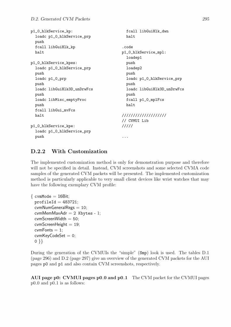
D.2. Generated CVM Packets 295
p1_0_hlkService_kp:loadc p1_0_hlkService_prppushfcall libGuiHlk_kphalt
p1_0_hlkService_kpes:loadc p1_0_hlkService_prppushloadc p1_0_prppushloadc libGuiHlk3D_unDrwFcspushloadc libMisc_emptyProcpushfcall libGui_mvFcshalt
p1_0_hlkService_kpe:loadc p1_0_hlkService_prppush
fcall libGuiHlk_dwnhalt
.codep1_0_hlkService_mpl:loadep1pushloadep2pushloadc p1_0_hlkService_prppushloadc libGuiHlk3D_unDrwFcspushfcall p1_0_mplFcshalt
////////////////////// CVMUI Lib/////
...
D.2.2 With Customization
The implemented customization method is only for demonstration purpose and thereforewill not be specified in detail. Instead, CVM screenshots and some selected CVMA codesamples of the generated CVM packets will be presented. The implemented customizationmethod is particularly applicable to very small client devices like wrist watches that mayhave the following exemplary CVM profile:
{ cvmMode = 16Bit;profileId = 483721;cvmNumGeneralRegs = 10;cvmMemMaxAdr = 2 Kbytes - 1;cvmScreenWidth = 50;cvmScreenHeight = 19;cvmFonts = 1;cvmKeyCodeSet = 0;0 }}
During the generation of the CVMUIs the “simple” (Smp) look is used. The tables D.1(page 296) and D.2 (page 297) give an overview of the generated CVM packets for the AUIpages p0 and p1 and also contain CVM screenshots, respectively.
AUI page p0: CVMUI pages p0 0 and p0 1 The CVM packet for the CVMUI pagesp0 0 and p0 1 is as follows:

296 D. CVM Packet Server: Example
CVM packet CVM packet size [Bytes] CVMUI page CVM Screenshot
0 320 p0 0
p0 1
1 348 p0 2
p0 3
2 349 p0 4
p0 5
3 349 p0 6
p0 7
4 349 p0 8
p0 9
5 344 p0 10
p0 11
6 1291 p0 12
p0 13
7 1293 p0 14
p0 15
8 999 p0 16
p0 17
Table D.1: Customized CVM Packets: registration.aui, CVMUI pages for AUIpage p0
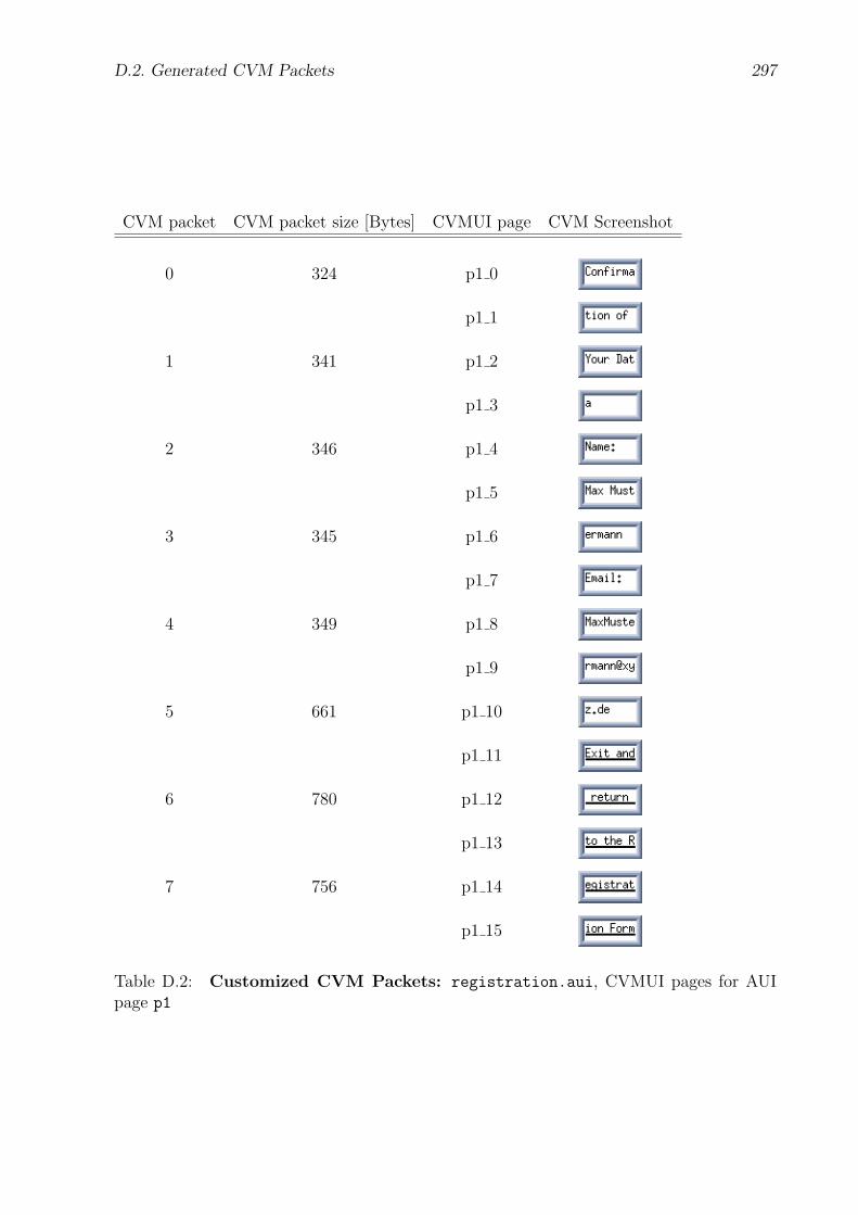
D.2. Generated CVM Packets 297
CVM packet CVM packet size [Bytes] CVMUI page CVM Screenshot
0 324 p1 0
p1 1
1 341 p1 2
p1 3
2 346 p1 4
p1 5
3 345 p1 6
p1 7
4 349 p1 8
p1 9
5 661 p1 10
p1 11
6 780 p1 12
p1 13
7 756 p1 14
p1 15
Table D.2: Customized CVM Packets: registration.aui, CVMUI pages for AUIpage p1

298 D. CVM Packet Server: Example
.16Bit
.codeloadcr p0_0_mainjmp
////////////////////// Misc/////
.const_cil 2_cvmScreenWidth 50_cvmScreenHeight 19
.dataString _hostAdrSrv "127.0.0.1"
////////////////////// Page Numbers/////
.const_pageNo 0_p0 0_p1 1_pNotExist 2_pIllegal 3
.dataInt _subpageNo
////////////////////// Service Commands/////
.constsvcCmd_Reset 0svcCmd_Submit 1
////////////////////// Service Variables/////
.const_svIdxLen 1_svIdx_name 1_svIdx_email 2
.dataInt _svBufIdx 0
Bytes _svBuf _svIdxLen + 2
.code
.fct _svBufIdx_reset (){loadc_0store _svBufIdxreturn}
////////////////////// p0_0: Attributes/////
.constp0_0_x 0p0_0_y 0p0_0_w _cvmScreenWidthp0_0_h _cvmScreenHeightp0_0_fgr 0p0_0_fgg 0p0_0_fgb 0p0_0_bgr 255p0_0_bgg 255p0_0_bgb 255p0_0_fc fcFixedStandardp0_0_fs 13p0_0_img ""p0_0_imgStyle 0
.dataBytes p0_0_prp [ p0_0_et ]Int p0_0_bInit 0
////////////////////// p0_0: Misc/////
.codep0_0_main:loadc_0store _subpageNofcall p0_0_initfcall p0_0_drwloadc p0_0_prppushloadc libMisc_emptyProcpushfcall libGui_setFcsenableeventshalt
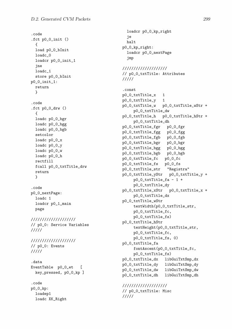
D.2. Generated CVM Packets 299
.code
.fct p0_0_init (){load p0_0_bInitloadc_0loadcr p0_0_init_1jneloadc_1store p0_0_bInit
p0_0_init_1:return}
.code
.fct p0_0_drw (){loadc p0_0_bgrloadc p0_0_bggloadc p0_0_bgbsetcolorloadc p0_0_xloadc p0_0_yloadc p0_0_wloadc p0_0_hrectfillfcall p0_0_txtTitle_drwreturn}
.codep0_0_nextPage:loadc 1loadcr p0_1_mainpage
////////////////////// p0_0: Service Variables/////
////////////////////// p0_0: Events/////
.dataEventTable p0_0_et [key_pressed, p0_0_kp ]
.codep0_0_kp:loadep1loadc XK_Right
loadcr p0_0_kp_rightjehalt
p0_0_kp_right:loadcr p0_0_nextPagejmp
////////////////////// p0_0_txtTitle: Attributes/////
.constp0_0_txtTitle_x 1p0_0_txtTitle_y 1p0_0_txtTitle_w p0_0_txtTitle_wStr +
p0_0_txtTitle_dwp0_0_txtTitle_h p0_0_txtTitle_hStr +
p0_0_txtTitle_dhp0_0_txtTitle_fgr p0_0_fgrp0_0_txtTitle_fgg p0_0_fggp0_0_txtTitle_fgb p0_0_fgbp0_0_txtTitle_bgr p0_0_bgrp0_0_txtTitle_bgg p0_0_bggp0_0_txtTitle_bgb p0_0_bgbp0_0_txtTitle_fc p0_0_fcp0_0_txtTitle_fs p0_0_fsp0_0_txtTitle_str "Registra"p0_0_txtTitle_yStr p0_0_txtTitle_y +
p0_0_txtTitle_fa - 1 +p0_0_txtTitle_dy
p0_0_txtTitle_xStr p0_0_txtTitle_x +p0_0_txtTitle_dx
p0_0_txtTitle_wStrtextWidth(p0_0_txtTitle_str,p0_0_txtTitle_fc,p0_0_txtTitle_fs)
p0_0_txtTitle_hStrtextHeight(p0_0_txtTitle_str,p0_0_txtTitle_fc,p0_0_txtTitle_fs, 0)
p0_0_txtTitle_fafontAscent(p0_0_txtTitle_fc,p0_0_txtTitle_fs)
p0_0_txtTitle_dx libGuiTxtSmp_dxp0_0_txtTitle_dy libGuiTxtSmp_dyp0_0_txtTitle_dw libGuiTxtSmp_dwp0_0_txtTitle_dh libGuiTxtSmp_dh
////////////////////// p0_0_txtTitle: Misc/////
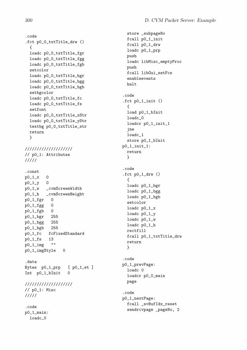
300 D. CVM Packet Server: Example
.code
.fct p0_0_txtTitle_drw (){loadc p0_0_txtTitle_fgrloadc p0_0_txtTitle_fggloadc p0_0_txtTitle_fgbsetcolorloadc p0_0_txtTitle_bgrloadc p0_0_txtTitle_bggloadc p0_0_txtTitle_bgbsetbgcolorloadc p0_0_txtTitle_fcloadc p0_0_txtTitle_fssetfontloadc p0_0_txtTitle_xStrloadc p0_0_txtTitle_yStrtextbg p0_0_txtTitle_strreturn}
////////////////////// p0_1: Attributes/////
.constp0_1_x 0p0_1_y 0p0_1_w _cvmScreenWidthp0_1_h _cvmScreenHeightp0_1_fgr 0p0_1_fgg 0p0_1_fgb 0p0_1_bgr 255p0_1_bgg 255p0_1_bgb 255p0_1_fc fcFixedStandardp0_1_fs 13p0_1_img ""p0_1_imgStyle 0
.dataBytes p0_1_prp [ p0_1_et ]Int p0_1_bInit 0
////////////////////// p0_1: Misc/////
.codep0_1_main:
loadc_0
store _subpageNofcall p0_1_initfcall p0_1_drwloadc p0_1_prppushloadc libMisc_emptyProcpushfcall libGui_setFcsenableeventshalt
.code
.fct p0_1_init (){load p0_1_bInitloadc_0loadcr p0_1_init_1jneloadc_1store p0_1_bInit
p0_1_init_1:return}
.code
.fct p0_1_drw (){loadc p0_1_bgrloadc p0_1_bggloadc p0_1_bgbsetcolorloadc p0_1_xloadc p0_1_yloadc p0_1_wloadc p0_1_hrectfillfcall p0_1_txtTitle_drwreturn}
.codep0_1_prevPage:loadc 0loadcr p0_0_mainpage
.codep0_1_nextPage:fcall _svBufIdx_resetsendrcvpage _pageNo, 2

D.2. Generated CVM Packets 301
////////////////////// p0_1: Service Variables/////
////////////////////// p0_1: Events/////
.dataEventTable p0_1_et [key_pressed, p0_1_kp ]
.codep0_1_kp:loadep1loadc XK_Leftloadcr p0_1_kp_leftjeloadep1loadc XK_Rightloadcr p0_1_kp_rightjehalt
p0_1_kp_left:loadcr p0_1_prevPagejmp
p0_1_kp_right:loadcr p0_1_nextPagejmp
////////////////////// p0_1_txtTitle: Attributes/////
.constp0_1_txtTitle_x 1p0_1_txtTitle_y 1p0_1_txtTitle_w p0_1_txtTitle_wStr +
p0_1_txtTitle_dwp0_1_txtTitle_h p0_1_txtTitle_hStr +
p0_1_txtTitle_dhp0_1_txtTitle_fgr p0_1_fgrp0_1_txtTitle_fgg p0_1_fggp0_1_txtTitle_fgb p0_1_fgbp0_1_txtTitle_bgr p0_1_bgrp0_1_txtTitle_bgg p0_1_bggp0_1_txtTitle_bgb p0_1_bgbp0_1_txtTitle_fc p0_1_fcp0_1_txtTitle_fs p0_1_fsp0_1_txtTitle_str "tion"
p0_1_txtTitle_yStr p0_1_txtTitle_y +p0_1_txtTitle_fa - 1 +p0_1_txtTitle_dy
p0_1_txtTitle_xStr p0_1_txtTitle_x +p0_1_txtTitle_dx
p0_1_txtTitle_wStrtextWidth(p0_1_txtTitle_str,p0_1_txtTitle_fc,p0_1_txtTitle_fs)
p0_1_txtTitle_hStrtextHeight(p0_1_txtTitle_str,p0_1_txtTitle_fc,p0_1_txtTitle_fs, 0)
p0_1_txtTitle_fafontAscent(p0_1_txtTitle_fc,p0_1_txtTitle_fs)
p0_1_txtTitle_dx libGuiTxtSmp_dxp0_1_txtTitle_dy libGuiTxtSmp_dyp0_1_txtTitle_dw libGuiTxtSmp_dwp0_1_txtTitle_dh libGuiTxtSmp_dh
////////////////////// p0_1_txtTitle: Misc/////
.code
.fct p0_1_txtTitle_drw (){loadc p0_1_txtTitle_fgrloadc p0_1_txtTitle_fggloadc p0_1_txtTitle_fgbsetcolorloadc p0_1_txtTitle_bgrloadc p0_1_txtTitle_bggloadc p0_1_txtTitle_bgbsetbgcolorloadc p0_1_txtTitle_fcloadc p0_1_txtTitle_fssetfontloadc p0_1_txtTitle_xStrloadc p0_1_txtTitle_yStrtextbg p0_1_txtTitle_strreturn}
////////////////////// CVMUI Lib/////
...
302 D. CVM Packet Server: Example
AUI page p0: CVMUI pages p0 2 and p0 3 The CVM packet for the CVMUI pagesp0 2 and p0 3 is as follows:
.16Bit
.codeloadcr p0_2_mainjmp
////////////////////// Misc/////
.const_cil 2_cvmScreenWidth 50_cvmScreenHeight 19
.dataString _hostAdrSrv "127.0.0.1"
////////////////////// Page Numbers/////
.const_pageNo 0_p0 0_p1 1_pNotExist 2_pIllegal 3
.dataInt _subpageNo
////////////////////// Service Commands/////
.constsvcCmd_Reset 0svcCmd_Submit 1
////////////////////// Service Variables/////
.const_svIdxLen 1_svIdx_name 1_svIdx_email 2
.dataInt _svBufIdx 0Bytes _svBuf _svIdxLen + 2
.code
.fct _svBufIdx_reset (){loadc_0store _svBufIdxreturn}
////////////////////// p0_2: Attributes/////
.constp0_2_x 0p0_2_y 0p0_2_w _cvmScreenWidthp0_2_h _cvmScreenHeightp0_2_fgr 0p0_2_fgg 0p0_2_fgb 0p0_2_bgr 255p0_2_bgg 255p0_2_bgb 255p0_2_fc fcFixedStandardp0_2_fs 13p0_2_img ""p0_2_imgStyle 0
.dataBytes p0_2_prp [ p0_2_et ]Int p0_2_bInit 0
////////////////////// p0_2: Misc/////
.codep0_2_main:loadc_0store _subpageNofcall p0_2_initfcall p0_2_drwloadc p0_2_prp
D.2. Generated CVM Packets 303
pushloadc libMisc_emptyProcpushfcall libGui_setFcsenableeventshalt
.code
.fct p0_2_init (){load p0_2_bInitloadc_0loadcr p0_2_init_1jneloadc_1store p0_2_bInit
p0_2_init_1:return}
.code
.fct p0_2_drw (){loadc p0_2_bgrloadc p0_2_bggloadc p0_2_bgbsetcolorloadc p0_2_xloadc p0_2_yloadc p0_2_wloadc p0_2_hrectfillfcall p0_2_txpIntro_drwreturn}
.codep0_2_prevPage:fcall _svBufIdx_resetsendrcvpage _pageNo, 1
.codep0_2_nextPage:loadc 3loadcr p0_3_mainpage
////////////////////// p0_2: Service Variables/////
////////////////////// p0_2: Events/////
.dataEventTable p0_2_et [key_pressed, p0_2_kp ]
.codep0_2_kp:loadep1loadc XK_Leftloadcr p0_2_kp_leftjeloadep1loadc XK_Rightloadcr p0_2_kp_rightjehalt
p0_2_kp_left:loadcr p0_2_prevPagejmp
p0_2_kp_right:loadcr p0_2_nextPagejmp
////////////////////// p0_2_txpIntro: Attributes/////
.constp0_2_txpIntro_x 1p0_2_txpIntro_y 1p0_2_txpIntro_w p0_2_txpIntro_wStr +
p0_2_txpIntro_dwp0_2_txpIntro_h p0_2_txpIntro_hStr +
p0_2_txpIntro_dhp0_2_txpIntro_fgr p0_2_fgrp0_2_txpIntro_fgg p0_2_fggp0_2_txpIntro_fgb p0_2_fgbp0_2_txpIntro_bgr p0_2_bgrp0_2_txpIntro_bgg p0_2_bggp0_2_txpIntro_bgb p0_2_bgbp0_2_txpIntro_fc p0_2_fcp0_2_txpIntro_fs p0_2_fsp0_2_txpIntro_str "Welcome "p0_2_txpIntro_yStr p0_2_txpIntro_y +
p0_2_txpIntro_fa - 1 +p0_2_txpIntro_dy
p0_2_txpIntro_xStr p0_2_txpIntro_x +p0_2_txpIntro_dx

304 D. CVM Packet Server: Example
p0_2_txpIntro_wStrtextWidth(p0_2_txpIntro_str,p0_2_txpIntro_fc,p0_2_txpIntro_fs)
p0_2_txpIntro_hStrtextHeight(p0_2_txpIntro_str,p0_2_txpIntro_fc,p0_2_txpIntro_fs, 0)
p0_2_txpIntro_fafontAscent(p0_2_txpIntro_fc,p0_2_txpIntro_fs)
p0_2_txpIntro_dx libGuiTxtSmp_dxp0_2_txpIntro_dy libGuiTxtSmp_dyp0_2_txpIntro_dw libGuiTxtSmp_dwp0_2_txpIntro_dh libGuiTxtSmp_dh
////////////////////// p0_2_txpIntro: Misc/////
.code
.fct p0_2_txpIntro_drw (){loadc p0_2_txpIntro_fgrloadc p0_2_txpIntro_fggloadc p0_2_txpIntro_fgbsetcolorloadc p0_2_txpIntro_bgrloadc p0_2_txpIntro_bggloadc p0_2_txpIntro_bgbsetbgcolorloadc p0_2_txpIntro_fcloadc p0_2_txpIntro_fssetfontloadc p0_2_txpIntro_xStrloadc p0_2_txpIntro_yStrtextbg p0_2_txpIntro_strreturn}
////////////////////// p0_3: Attributes/////
.constp0_3_x 0p0_3_y 0p0_3_w _cvmScreenWidthp0_3_h _cvmScreenHeightp0_3_fgr 0p0_3_fgg 0
p0_3_fgb 0p0_3_bgr 255p0_3_bgg 255p0_3_bgb 255p0_3_fc fcFixedStandardp0_3_fs 13p0_3_img ""p0_3_imgStyle 0
.dataBytes p0_3_prp [ p0_3_et ]Int p0_3_bInit 0
////////////////////// p0_3: Misc/////
.codep0_3_main:loadc_0store _subpageNofcall p0_3_initfcall p0_3_drwloadc p0_3_prppushloadc libMisc_emptyProcpushfcall libGui_setFcsenableeventshalt
.code
.fct p0_3_init (){load p0_3_bInitloadc_0loadcr p0_3_init_1jneloadc_1store p0_3_bInit
p0_3_init_1:return}
.code
.fct p0_3_drw (){loadc p0_3_bgrloadc p0_3_bggloadc p0_3_bgbsetcolor

D.2. Generated CVM Packets 305
loadc p0_3_xloadc p0_3_yloadc p0_3_wloadc p0_3_hrectfillfcall p0_3_txpIntro_drwreturn}
.codep0_3_prevPage:loadc 2loadcr p0_2_mainpage
.codep0_3_nextPage:fcall _svBufIdx_resetsendrcvpage _pageNo, 4
////////////////////// p0_3: Service Variables/////
////////////////////// p0_3: Events/////
.dataEventTable p0_3_et [key_pressed, p0_3_kp ]
.codep0_3_kp:loadep1loadc XK_Leftloadcr p0_3_kp_leftjeloadep1loadc XK_Rightloadcr p0_3_kp_rightjehalt
p0_3_kp_left:loadcr p0_3_prevPagejmp
p0_3_kp_right:loadcr p0_3_nextPagejmp
////////////////////
// p0_3_txpIntro: Attributes/////
.constp0_3_txpIntro_x 1p0_3_txpIntro_y 1p0_3_txpIntro_w p0_3_txpIntro_wStr +
p0_3_txpIntro_dwp0_3_txpIntro_h p0_3_txpIntro_hStr +
p0_3_txpIntro_dhp0_3_txpIntro_fgr p0_3_fgrp0_3_txpIntro_fgg p0_3_fggp0_3_txpIntro_fgb p0_3_fgbp0_3_txpIntro_bgr p0_3_bgrp0_3_txpIntro_bgg p0_3_bggp0_3_txpIntro_bgb p0_3_bgbp0_3_txpIntro_fc p0_3_fcp0_3_txpIntro_fs p0_3_fsp0_3_txpIntro_str "to the r"p0_3_txpIntro_yStr p0_3_txpIntro_y +
p0_3_txpIntro_fa - 1 +p0_3_txpIntro_dy
p0_3_txpIntro_xStr p0_3_txpIntro_x +p0_3_txpIntro_dx
p0_3_txpIntro_wStrtextWidth(p0_3_txpIntro_str,p0_3_txpIntro_fc,p0_3_txpIntro_fs)
p0_3_txpIntro_hStrtextHeight(p0_3_txpIntro_str,p0_3_txpIntro_fc,p0_3_txpIntro_fs, 0)
p0_3_txpIntro_fafontAscent(p0_3_txpIntro_fc,p0_3_txpIntro_fs)
p0_3_txpIntro_dx libGuiTxtSmp_dxp0_3_txpIntro_dy libGuiTxtSmp_dyp0_3_txpIntro_dw libGuiTxtSmp_dwp0_3_txpIntro_dh libGuiTxtSmp_dh
////////////////////// p0_3_txpIntro: Misc/////
.code
.fct p0_3_txpIntro_drw (){loadc p0_3_txpIntro_fgrloadc p0_3_txpIntro_fggloadc p0_3_txpIntro_fgbsetcolor

306 D. CVM Packet Server: Example
loadc p0_3_txpIntro_bgrloadc p0_3_txpIntro_bggloadc p0_3_txpIntro_bgbsetbgcolorloadc p0_3_txpIntro_fcloadc p0_3_txpIntro_fssetfontloadc p0_3_txpIntro_xStrloadc p0_3_txpIntro_yStr
textbg p0_3_txpIntro_strreturn}
////////////////////// CVMUI Lib/////
...
AUI page p0: CVMUI pages p0 12 and p0 13 The CVM packet for the CVMUIpages p0 12 and p0 13 is as follows:
.16Bit
.codeloadcr p0_12_mainjmp
////////////////////// Misc/////
.const_cil 2_cvmScreenWidth 50_cvmScreenHeight 19
.dataString _hostAdrSrv "127.0.0.1"
////////////////////// Page Numbers/////
.const_pageNo 0_p0 0_p1 1_pNotExist 2_pIllegal 3
.dataInt _subpageNo
////////////////////// Service Commands/////
.const
svcCmd_Reset 0svcCmd_Submit 1
////////////////////// Service Variables/////
.const_svIdxLen 1_svIdx_name 1_svIdx_email 2
.dataInt _svBufIdx 0Bytes _svBuf _svIdxLen +
p0_13_ixtName_svBufLen +_svIdxLen + 2
.code
.fct _svBufIdx_reset (){loadc_0store _svBufIdxreturn}
.code
.fct _svBuf_write (){fcall _svBufIdx_resetfcall p0_13_svBuf_writereturn}
////////////////////// p0_12: Attributes/////
D.2. Generated CVM Packets 307
.constp0_12_x 0p0_12_y 0p0_12_w _cvmScreenWidthp0_12_h _cvmScreenHeightp0_12_fgr 0p0_12_fgg 0p0_12_fgb 0p0_12_bgr 255p0_12_bgg 255p0_12_bgb 255p0_12_fc fcFixedStandardp0_12_fs 13p0_12_img ""p0_12_imgStyle 0
.dataBytes p0_12_prp [ p0_12_et ]Int p0_12_bInit 0
////////////////////// p0_12: Misc/////
.codep0_12_main:loadc_0store _subpageNofcall p0_12_initfcall p0_12_drwloadc p0_12_prppushloadc libMisc_emptyProcpushfcall libGui_setFcsenableeventshalt
.code
.fct p0_12_init (){load p0_12_bInitloadc_0loadcr p0_12_init_1jneloadc_1store p0_12_bInit
p0_12_init_1:return}
.code
.fct p0_12_drw (){loadc p0_12_bgrloadc p0_12_bggloadc p0_12_bgbsetcolorloadc p0_12_xloadc p0_12_yloadc p0_12_wloadc p0_12_hrectfillfcall p0_12_txtName_drwreturn}
.codep0_12_prevPage:fcall _svBuf_writesendrcvpage _pageNo, 11
.codep0_12_nextPage:loadc 13loadcr p0_13_mainpage
////////////////////// p0_12: Service Variables/////
////////////////////// p0_12: Events/////
.dataEventTable p0_12_et [key_pressed, p0_12_kp ]
.codep0_12_kp:loadep1loadc XK_Leftloadcr p0_12_kp_leftjeloadep1loadc XK_Rightloadcr p0_12_kp_rightjehalt
p0_12_kp_left:
308 D. CVM Packet Server: Example
loadcr p0_12_prevPagejmp
p0_12_kp_right:loadcr p0_12_nextPagejmp
////////////////////// p0_12_txtName: Attributes/////
.constp0_12_txtName_x 1p0_12_txtName_y 1p0_12_txtName_w p0_12_txtName_wStr +
p0_12_txtName_dwp0_12_txtName_h p0_12_txtName_hStr +
p0_12_txtName_dhp0_12_txtName_fgr p0_12_fgrp0_12_txtName_fgg p0_12_fggp0_12_txtName_fgb p0_12_fgbp0_12_txtName_bgr p0_12_bgrp0_12_txtName_bgg p0_12_bggp0_12_txtName_bgb p0_12_bgbp0_12_txtName_fc p0_12_fcp0_12_txtName_fs p0_12_fsp0_12_txtName_str "Name"p0_12_txtName_yStr p0_12_txtName_y +
p0_12_txtName_fa - 1 +p0_12_txtName_dy
p0_12_txtName_xStr p0_12_txtName_x +p0_12_txtName_dx
p0_12_txtName_wStrtextWidth(p0_12_txtName_str,p0_12_txtName_fc,p0_12_txtName_fs)
p0_12_txtName_hStrtextHeight(p0_12_txtName_str,p0_12_txtName_fc,p0_12_txtName_fs, 0)
p0_12_txtName_fafontAscent(p0_12_txtName_fc,p0_12_txtName_fs)
p0_12_txtName_dx libGuiTxtSmp_dxp0_12_txtName_dy libGuiTxtSmp_dyp0_12_txtName_dw libGuiTxtSmp_dwp0_12_txtName_dh libGuiTxtSmp_dh
////////////////////// p0_12_txtName: Misc/////
.code
.fct p0_12_txtName_drw (){loadc p0_12_txtName_fgrloadc p0_12_txtName_fggloadc p0_12_txtName_fgbsetcolorloadc p0_12_txtName_bgrloadc p0_12_txtName_bggloadc p0_12_txtName_bgbsetbgcolorloadc p0_12_txtName_fcloadc p0_12_txtName_fssetfontloadc p0_12_txtName_xStrloadc p0_12_txtName_yStrtextbg p0_12_txtName_strreturn}
////////////////////// p0_13: Attributes/////
.constp0_13_x 0p0_13_y 0p0_13_w _cvmScreenWidthp0_13_h _cvmScreenHeightp0_13_fgr 0p0_13_fgg 0p0_13_fgb 0p0_13_bgr 255p0_13_bgg 255p0_13_bgb 255p0_13_fc fcFixedStandardp0_13_fs 13p0_13_img ""p0_13_imgStyle 0
.dataBytes p0_13_prp [ p0_13_et ]Int p0_13_bInit 0
////////////////////// p0_13: Misc/////
.codep0_13_main:loadc_0
D.2. Generated CVM Packets 309
store _subpageNofcall p0_13_initfcall p0_13_drwloadc p0_13_ixtName_prppushloadc libGuiIxtSmp_drwFcspushfcall libGui_setFcsenableeventshalt
.code
.fct p0_13_init (){load p0_13_bInitloadc_0loadcr p0_13_init_1jnefcall p0_13_ixtName_initloadc_1store p0_13_bInit
p0_13_init_1:return}
.code
.fct p0_13_drw (){loadc p0_13_bgrloadc p0_13_bggloadc p0_13_bgbsetcolorloadc p0_13_xloadc p0_13_yloadc p0_13_wloadc p0_13_hrectfillloadc p0_13_ixtName_prppushfcall libGuiIxtSmp_drwreturn}
.codep0_13_prevPage:loadc 12loadcr p0_12_mainpage
.codep0_13_nextPage:
fcall _svBuf_writesendrcvpage _pageNo, 14
////////////////////// p0_13: Service Variables/////
.code
.fct p0_13_svBuf_write (){fcall p0_13_ixtName_svBuf_writereturn}
////////////////////// p0_13: Events/////
.dataEventTable p0_13_et [key_pressed, p0_13_kp ]
.codep0_13_kp:loadep1loadc XK_Tabloadcr p0_13_kp_tabjeloadep1loadc XK_Leftloadcr p0_13_kp_leftjeloadep1loadc XK_Rightloadcr p0_13_kp_rightjehalt
p0_13_kp_tab:loadc p0_13_prppushloadc p0_13_ixtName_prppushloadc libMisc_emptyProcpushloadc libGuiIxtSmp_drwFcspushfcall libGui_mvFcshalt
p0_13_kp_left:loadcr p0_13_prevPagejmp

310 D. CVM Packet Server: Example
p0_13_kp_right:loadcr p0_13_nextPagejmp
////////////////////// p0_13_ixtName: Attributes/////
.constp0_13_ixtName_x 1p0_13_ixtName_y 1p0_13_ixtName_w 48p0_13_ixtName_h p0_13_ixtName_hStr +
p0_13_ixtName_dhp0_13_ixtName_fgr p0_13_fgrp0_13_ixtName_fgg p0_13_fggp0_13_ixtName_fgb p0_13_fgbp0_13_ixtName_bgr p0_13_bgrp0_13_ixtName_bgg p0_13_bggp0_13_ixtName_bgb p0_13_bgbp0_13_ixtName_fc p0_13_fcp0_13_ixtName_fs p0_13_fs
.dataBytes p0_13_ixtName_str
p0_13_ixtName_strLenMax + 3
.constp0_13_ixtName_yStr p0_13_ixtName_y +
p0_13_ixtName_fa - 1 +p0_13_ixtName_dy
p0_13_ixtName_strLenMax 80p0_13_ixtName_svIdx _svIdx_namep0_13_ixtName_svBufLen
p0_13_ixtName_strLenMax + 3p0_13_ixtName_xStr p0_13_ixtName_x +
p0_13_ixtName_dxp0_13_ixtName_wStr p0_13_ixtName_w -
p0_13_ixtName_dwp0_13_ixtName_hStr p0_13_ixtName_fhp0_13_ixtName_yaStr p0_13_ixtName_y
+ p0_13_ixtName_dy
.dataString p0_13_ixtName_strInit "your
name"
.constp0_13_ixtName_wChar textWidth(" ",
p0_13_ixtName_fc,p0_13_ixtName_fs)
p0_13_ixtName_strPos -12p0_13_ixtName_fa
fontAscent(p0_13_ixtName_fc,p0_13_ixtName_fs)
p0_13_ixtName_fhfontHeight(p0_13_ixtName_fc,p0_13_ixtName_fs)
p0_13_ixtName_dx libGuiIxtSmp_dxp0_13_ixtName_dy libGuiIxtSmp_dyp0_13_ixtName_dw libGuiIxtSmp_dwp0_13_ixtName_dh libGuiIxtSmp_dh
.dataBytes p0_13_ixtName_prp [
p0_13_ixtName_et,p0_13_ixtName_x, p0_13_ixtName_y,p0_13_ixtName_w, p0_13_ixtName_h,p0_13_ixtName_fgr,p0_13_ixtName_fgg,p0_13_ixtName_fgb,p0_13_ixtName_bgr,p0_13_ixtName_bgg,p0_13_ixtName_bgb,p0_13_ixtName_fc,p0_13_ixtName_fs,p0_13_ixtName_str,p0_13_ixtName_xStr,p0_13_ixtName_yStr,p0_13_ixtName_wStr,p0_13_ixtName_hStr,p0_13_ixtName_yaStr,p0_13_ixtName_strLenMax,p0_13_ixtName_wChar,p0_13_ixtName_strPos ]
////////////////////// p0_13_ixtName: Init/////
.code
.fct p0_13_ixtName_init (){loadc p0_13_ixtName_strPosloadc p0_13_ixtName_prploadc libGui_strPosOfsaddstorealoadc p0_13_ixtName_strpushloadc p0_13_ixtName_strInitpush
D.2. Generated CVM Packets 311
fcall libMisc_strCpreturn}
////////////////////// p0_13_ixtName: Events/////
.dataEventTable p0_13_ixtName_et [key_pressed, p0_13_ixtName_kp,key_pressed_escape,
p0_13_ixtName_kpes,1, p0_13_et ]
.codep0_13_ixtName_kp:loadc p0_13_ixtName_prppushfcall libGuiIxt_kphalt
p0_13_ixtName_kpes:loadc p0_13_ixtName_prppushloadc p0_13_prppushloadc libGuiIxtSmp_unDrwFcspushloadc libMisc_emptyProcpushfcall libGui_mvFcshalt
////////////////////// p0_13_ixtName: Service Variables/////
.code
.fct p0_13_ixtName_svBuf_write (){loadc p0_13_ixtName_svIdxloadc _svBufload _svBufIdxastore1load _svBufIdxloadc 1addstore _svBufIdxloadc _svBufload _svBufIdxaddpushloadc p0_13_ixtName_strpushfcall libMisc_strCpload _svBufIdxincsploadc p0_13_ixtName_strpushfcall libMisc_strLenpopaddloadc 3addstore _svBufIdxreturn}
////////////////////// CVMUI Lib/////
...
AUI page p0: CVMUI pages p0 16 and p0 17 The CVM packet for the CVMUIpages p0 16 and p0 17 is as follows:
.16Bit
.codeloadcr p0_16_mainjmp
////////////////////// Misc/////
.const_cil 2_cvmScreenWidth 50_cvmScreenHeight 19
.dataString _hostAdrSrv "127.0.0.1"
////////////////////
312 D. CVM Packet Server: Example
// Page Numbers/////
.const_pageNo 0_p0 0_p1 1_pNotExist 2_pIllegal 3
.dataInt _subpageNo
////////////////////// Service Commands/////
.constsvcCmd_Reset 0svcCmd_Submit 1
////////////////////// Service Variables/////
.const_svIdxLen 1_svIdx_name 1_svIdx_email 2
.dataInt _svBufIdx 0Bytes _svBuf _svIdxLen + 2
.code
.fct _svBufIdx_reset (){loadc_0store _svBufIdxreturn}
.code
.fct _svBuf_svcCmd_write (IntsvcCmdIdx)
{loadc_0loadc _svBufload _svBufIdxastore1load _svBufIdx
loadc _svIdxLenaddstore _svBufIdxload svcCmdIdxloadc _svBufload _svBufIdxastore2load _svBufIdxloadc 2addstore _svBufIdxreturn}
.code
.fct _svBuf_write (){fcall _svBufIdx_resetreturn}
////////////////////// p0_16: Attributes/////
.constp0_16_x 0p0_16_y 0p0_16_w _cvmScreenWidthp0_16_h _cvmScreenHeightp0_16_fgr 0p0_16_fgg 0p0_16_fgb 0p0_16_bgr 255p0_16_bgg 255p0_16_bgb 255p0_16_fc fcFixedStandardp0_16_fs 13p0_16_img ""p0_16_imgStyle 0
.dataBytes p0_16_prp [ p0_16_et ]Int p0_16_bInit 0
////////////////////// p0_16: Misc/////
.codep0_16_main:

D.2. Generated CVM Packets 313
loadc_0store _subpageNofcall p0_16_initfcall p0_16_drwloadc p0_16_btnReset_prppushloadc libGuiBtnSmp_drwFcspushfcall libGui_setFcsenableeventshalt
.code
.fct p0_16_init (){load p0_16_bInitloadc_0loadcr p0_16_init_1jneloadc_1store p0_16_bInit
p0_16_init_1:return}
.code
.fct p0_16_drw (){loadc p0_16_bgrloadc p0_16_bggloadc p0_16_bgbsetcolorloadc p0_16_xloadc p0_16_yloadc p0_16_wloadc p0_16_hrectfillloadc p0_16_btnReset_prppushfcall libGuiBtnSmp_drwreturn}
.codep0_16_prevPage:fcall _svBufIdx_resetsendrcvpage _pageNo, 15
.codep0_16_nextPage:loadc 17
loadcr p0_17_mainpage
////////////////////// p0_16: Service Variables/////
////////////////////// p0_16: Events/////
.dataEventTable p0_16_et [key_pressed, p0_16_kp ]
.codep0_16_kp:loadep1loadc XK_Tabloadcr p0_16_kp_tabjeloadep1loadc XK_Leftloadcr p0_16_kp_leftjeloadep1loadc XK_Rightloadcr p0_16_kp_rightjehalt
p0_16_kp_tab:loadc p0_16_prppushloadc p0_16_btnReset_prppushloadc libMisc_emptyProcpushloadc libGuiBtnSmp_drwFcspushfcall libGui_mvFcshalt
p0_16_kp_left:loadcr p0_16_prevPagejmp
p0_16_kp_right:loadcr p0_16_nextPagejmp
////////////////////// p0_16_btnReset: Attributes/////
314 D. CVM Packet Server: Example
.constp0_16_btnReset_x 1p0_16_btnReset_y 1p0_16_btnReset_w p0_16_btnReset_wStr
+ p0_16_btnReset_dwp0_16_btnReset_h p0_16_btnReset_hStr
+ p0_16_btnReset_dhp0_16_btnReset_fgr p0_16_fgrp0_16_btnReset_fgg p0_16_fggp0_16_btnReset_fgb p0_16_fgbp0_16_btnReset_bgr p0_16_bgrp0_16_btnReset_bgg p0_16_bggp0_16_btnReset_bgb p0_16_bgbp0_16_btnReset_fc p0_16_fcp0_16_btnReset_fs p0_16_fsp0_16_btnReset_str "Reset"p0_16_btnReset_yStr p0_16_btnReset_y
+ p0_16_btnReset_fa - 1 +p0_16_btnReset_dy
p0_16_btnReset_img ""p0_16_btnReset_imgStyle 0p0_16_btnReset_xStr p0_16_btnReset_x
+ p0_16_btnReset_dxp0_16_btnReset_wStr
textWidth(p0_16_btnReset_str,p0_16_btnReset_fc,p0_16_btnReset_fs)
p0_16_btnReset_hStrp0_16_btnReset_fh
p0_16_btnReset_fafontAscent(p0_16_btnReset_fc,p0_16_btnReset_fs)
p0_16_btnReset_fhfontHeight(p0_16_btnReset_fc,p0_16_btnReset_fs)
p0_16_btnReset_dx libGuiBtnSmp_dxp0_16_btnReset_dy libGuiBtnSmp_dyp0_16_btnReset_dw libGuiBtnSmp_dwp0_16_btnReset_dh libGuiBtnSmp_dh
.dataString p0_16_btnReset_str_
p0_16_btnReset_strString p0_16_btnReset_img_
p0_16_btnReset_imgBytes p0_16_btnReset_prp [
p0_16_btnReset_et,p0_16_btnReset_x,p0_16_btnReset_y,p0_16_btnReset_w,p0_16_btnReset_h,
p0_16_btnReset_fgr,p0_16_btnReset_fgg,p0_16_btnReset_fgb,p0_16_btnReset_bgr,p0_16_btnReset_bgg,p0_16_btnReset_bgb,p0_16_btnReset_fc,p0_16_btnReset_fs,p0_16_btnReset_str_,p0_16_btnReset_xStr,p0_16_btnReset_yStr,p0_16_btnReset_img_,p0_16_btnReset_imgStyle ]
////////////////////// p0_16_btnReset: Events/////
.dataEventTable p0_16_btnReset_et [key_pressed, p0_16_btnReset_kp,key_pressed_escape,
p0_16_btnReset_kpes,key_pressed_enter,
p0_16_btnReset_kpe,key_released, p0_16_btnReset_kr,key_released_enter,
p0_16_btnReset_kre,1, p0_16_et ]
.codep0_16_btnReset_kp:loadep1loadc XK_spaceloadcr p0_16_btnReset_kp_spacejehalt
p0_16_btnReset_kp_space:fcall p0_16_btnReset_evDwnhalt
p0_16_btnReset_kpes:loadc p0_16_btnReset_prppushloadc p0_16_prppushloadc libGuiBtnSmp_unDrwFcspushloadc libMisc_emptyProcpush

D.2. Generated CVM Packets 315
fcall libGui_mvFcshalt
p0_16_btnReset_kpe:fcall p0_16_btnReset_evDwnhalt
p0_16_btnReset_kr:loadep1loadc XK_spaceloadcr p0_16_btnReset_kr_spacejehalt
p0_16_btnReset_kr_space:fcall p0_16_btnReset_evUphalt
p0_16_btnReset_kre:fcall p0_16_btnReset_evUphalt
.code
.fct p0_16_btnReset_evDwn (){loadc p0_16_btnReset_prppushfcall libGuiBtnSmp_dwn
fcall _svBufIdx_resetfcall_I _svBuf_svcCmd_write,svcCmd_Resetsendrcvpage_a _pageNo,_subpageNo
return}
.fct p0_16_btnReset_evUp (){loadc p0_16_btnReset_prppushfcall libGuiBtnSmp_upreturn}
////////////////////// p0_17: Attributes/////
.constp0_17_x 0p0_17_y 0
p0_17_w _cvmScreenWidthp0_17_h _cvmScreenHeightp0_17_fgr 0p0_17_fgg 0p0_17_fgb 0p0_17_bgr 255p0_17_bgg 255p0_17_bgb 255p0_17_fc fcFixedStandardp0_17_fs 13p0_17_img ""p0_17_imgStyle 0
.dataBytes p0_17_prp [ p0_17_et ]Int p0_17_bInit 0
////////////////////// p0_17: Misc/////
.codep0_17_main:loadc_0store _subpageNofcall p0_17_initfcall p0_17_drwloadc p0_17_btnSubmit_prppushloadc libGuiBtnSmp_drwFcspushfcall libGui_setFcsenableeventshalt
.code
.fct p0_17_init (){load p0_17_bInitloadc_0loadcr p0_17_init_1jneloadc_1store p0_17_bInit
p0_17_init_1:return}
.code
.fct p0_17_drw (){
316 D. CVM Packet Server: Example
loadc p0_17_bgrloadc p0_17_bggloadc p0_17_bgbsetcolorloadc p0_17_xloadc p0_17_yloadc p0_17_wloadc p0_17_hrectfillloadc p0_17_btnSubmit_prppushfcall libGuiBtnSmp_drwreturn}
.codep0_17_prevPage:
loadc 16loadcr p0_16_mainpage
////////////////////// p0_17: Service Variables/////
////////////////////// p0_17: Events/////
.dataEventTable p0_17_et [
key_pressed, p0_17_kp ]
.codep0_17_kp:
loadep1loadc XK_Tabloadcr p0_17_kp_tabjeloadep1loadc XK_Leftloadcr p0_17_kp_leftjehalt
p0_17_kp_tab:loadc p0_17_prppushloadc p0_17_btnSubmit_prppushloadc libMisc_emptyProcpush
loadc libGuiBtnSmp_drwFcspushfcall libGui_mvFcshalt
p0_17_kp_left:loadcr p0_17_prevPagejmp
////////////////////// p0_17_btnSubmit: Attributes/////
.constp0_17_btnSubmit_x 1p0_17_btnSubmit_y 1p0_17_btnSubmit_w
p0_17_btnSubmit_wStr +p0_17_btnSubmit_dw
p0_17_btnSubmit_hp0_17_btnSubmit_hStr +p0_17_btnSubmit_dh
p0_17_btnSubmit_fgr p0_17_fgrp0_17_btnSubmit_fgg p0_17_fggp0_17_btnSubmit_fgb p0_17_fgbp0_17_btnSubmit_bgr p0_17_bgrp0_17_btnSubmit_bgg p0_17_bggp0_17_btnSubmit_bgb p0_17_bgbp0_17_btnSubmit_fc p0_17_fcp0_17_btnSubmit_fs p0_17_fsp0_17_btnSubmit_str "Submit"p0_17_btnSubmit_yStr
p0_17_btnSubmit_y +p0_17_btnSubmit_fa - 1 +p0_17_btnSubmit_dy
p0_17_btnSubmit_img ""p0_17_btnSubmit_imgStyle 0p0_17_btnSubmit_xStr
p0_17_btnSubmit_x +p0_17_btnSubmit_dx
p0_17_btnSubmit_wStrtextWidth(p0_17_btnSubmit_str,p0_17_btnSubmit_fc,p0_17_btnSubmit_fs)
p0_17_btnSubmit_hStrp0_17_btnSubmit_fh
p0_17_btnSubmit_fafontAscent(p0_17_btnSubmit_fc,p0_17_btnSubmit_fs)
p0_17_btnSubmit_fhfontHeight(p0_17_btnSubmit_fc,p0_17_btnSubmit_fs)
D.2. Generated CVM Packets 317
p0_17_btnSubmit_dx libGuiBtnSmp_dxp0_17_btnSubmit_dy libGuiBtnSmp_dyp0_17_btnSubmit_dw libGuiBtnSmp_dwp0_17_btnSubmit_dh libGuiBtnSmp_dh
.dataString p0_17_btnSubmit_str_
p0_17_btnSubmit_strString p0_17_btnSubmit_img_
p0_17_btnSubmit_imgBytes p0_17_btnSubmit_prp [
p0_17_btnSubmit_et,p0_17_btnSubmit_x,p0_17_btnSubmit_y,p0_17_btnSubmit_w,p0_17_btnSubmit_h,p0_17_btnSubmit_fgr,p0_17_btnSubmit_fgg,p0_17_btnSubmit_fgb,p0_17_btnSubmit_bgr,p0_17_btnSubmit_bgg,p0_17_btnSubmit_bgb,p0_17_btnSubmit_fc,p0_17_btnSubmit_fs,p0_17_btnSubmit_str_,p0_17_btnSubmit_xStr,p0_17_btnSubmit_yStr,p0_17_btnSubmit_img_,p0_17_btnSubmit_imgStyle ]
////////////////////// p0_17_btnSubmit: Events/////
.dataEventTable p0_17_btnSubmit_et [key_pressed, p0_17_btnSubmit_kp,key_pressed_escape,
p0_17_btnSubmit_kpes,key_pressed_enter,
p0_17_btnSubmit_kpe,key_released, p0_17_btnSubmit_kr,key_released_enter,
p0_17_btnSubmit_kre,1, p0_17_et ]
.codep0_17_btnSubmit_kp:loadep1loadc XK_spaceloadcr p0_17_btnSubmit_kp_space
jehalt
p0_17_btnSubmit_kp_space:fcall p0_17_btnSubmit_evDwnhalt
p0_17_btnSubmit_kpes:loadc p0_17_btnSubmit_prppushloadc p0_17_prppushloadc libGuiBtnSmp_unDrwFcspushloadc libMisc_emptyProcpushfcall libGui_mvFcshalt
p0_17_btnSubmit_kpe:fcall p0_17_btnSubmit_evDwnhalt
p0_17_btnSubmit_kr:loadep1loadc XK_spaceloadcr p0_17_btnSubmit_kr_spacejehalt
p0_17_btnSubmit_kr_space:fcall p0_17_btnSubmit_evUphalt
p0_17_btnSubmit_kre:fcall p0_17_btnSubmit_evUphalt
.code
.fct p0_17_btnSubmit_evDwn (){loadc p0_17_btnSubmit_prppushfcall libGuiBtnSmp_dwn
fcall _svBuf_writefcall_I _svBuf_svcCmd_write,svcCmd_Submitsendrcvpage _p1, 0
return}
318 D. CVM Packet Server: Example
.fct p0_17_btnSubmit_evUp (){loadc p0_17_btnSubmit_prppushfcall libGuiBtnSmp_upreturn}
////////////////////// CVMUI Lib/////
...
AUI page p1: CVMUI pages p1 12 and p1 13 The CVM packet for the CVMUIpages p1 12 and p1 13 is as follows:
.16Bit
.codeloadcr p1_12_mainjmp
////////////////////// Misc/////
.const_cil 2_cvmScreenWidth 50_cvmScreenHeight 19
.dataString _hostAdrSrv "127.0.0.1"
////////////////////// Page Numbers/////
.const_pageNo 1_p0 0_pNotExist 2_pIllegal 3
.dataInt _subpageNo
////////////////////// Service Commands/////
.constsvcCmd_Reset 0svcCmd_Submit 1
////////////////////// Service Variables/////
.const_svIdxLen 1_svIdx_name 1_svIdx_email 2
.dataInt _svBufIdx 0Bytes _svBuf _svIdxLen + 2
.code
.fct _svBufIdx_reset (){loadc_0store _svBufIdxreturn}
////////////////////// p1_12: Attributes/////
.constp1_12_x 0p1_12_y 0p1_12_w _cvmScreenWidthp1_12_h _cvmScreenHeightp1_12_fgr 0p1_12_fgg 0p1_12_fgb 0p1_12_bgr 255p1_12_bgg 255p1_12_bgb 255p1_12_fc fcFixedStandardp1_12_fs 13p1_12_img ""

D.2. Generated CVM Packets 319
p1_12_imgStyle 0
.dataBytes p1_12_prp [ p1_12_et ]Int p1_12_bInit 0
////////////////////// p1_12: Misc/////
.codep1_12_main:loadc_0store _subpageNofcall p1_12_initfcall p1_12_drwloadc p1_12_hlkService_prppushloadc libGuiHlkSmp_drwFcspushfcall libGui_setFcsenableeventshalt
.code
.fct p1_12_init (){load p1_12_bInitloadc_0loadcr p1_12_init_1jneloadc_1store p1_12_bInit
p1_12_init_1:return}
.code
.fct p1_12_drw (){loadc p1_12_bgrloadc p1_12_bggloadc p1_12_bgbsetcolorloadc p1_12_xloadc p1_12_yloadc p1_12_wloadc p1_12_hrectfillloadc p1_12_hlkService_prppush
fcall libGuiHlkSmp_drwreturn}
.codep1_12_prevPage:fcall _svBufIdx_resetsendrcvpage _pageNo, 11
.codep1_12_nextPage:loadc 13loadcr p1_13_mainpage
////////////////////// p1_12: Service Variables/////
////////////////////// p1_12: Events/////
.dataEventTable p1_12_et [key_pressed, p1_12_kp ]
.codep1_12_kp:loadep1loadc XK_Tabloadcr p1_12_kp_tabjeloadep1loadc XK_Leftloadcr p1_12_kp_leftjeloadep1loadc XK_Rightloadcr p1_12_kp_rightjehalt
p1_12_kp_tab:loadc p1_12_prppushloadc p1_12_hlkService_prppushloadc libMisc_emptyProcpushloadc libGuiHlkSmp_drwFcspush

320 D. CVM Packet Server: Example
fcall libGui_mvFcshalt
p1_12_kp_left:loadcr p1_12_prevPagejmp
p1_12_kp_right:loadcr p1_12_nextPagejmp
////////////////////// p1_12_hlkService: Attributes/////
.constp1_12_hlkService_x 1p1_12_hlkService_y 1p1_12_hlkService_w
p1_12_hlkService_wStr +p1_12_hlkService_dw
p1_12_hlkService_hp1_12_hlkService_hStr +p1_12_hlkService_dh
p1_12_hlkService_fgr p1_12_fgrp1_12_hlkService_fgg p1_12_fggp1_12_hlkService_fgb p1_12_fgbp1_12_hlkService_bgr p1_12_bgrp1_12_hlkService_bgg p1_12_bggp1_12_hlkService_bgb p1_12_bgbp1_12_hlkService_fc p1_12_fcp1_12_hlkService_fs p1_12_fsp1_12_hlkService_str " return "p1_12_hlkService_yStr
p1_12_hlkService_y +p1_12_hlkService_fa - 1 +p1_12_hlkService_dy
p1_12_hlkService_hostAdr "127.0.0.1"p1_12_hlkService_serviceNo 1p1_12_hlkService_xStr
p1_12_hlkService_x +p1_12_hlkService_dx
p1_12_hlkService_wStrtextWidth(p1_12_hlkService_str,p1_12_hlkService_fc,p1_12_hlkService_fs)
p1_12_hlkService_hStrp1_12_hlkService_fh
p1_12_hlkService_fafontAscent(p1_12_hlkService_fc,p1_12_hlkService_fs)
p1_12_hlkService_fhfontHeight(p1_12_hlkService_fc,
p1_12_hlkService_fs)p1_12_hlkService_dx libGuiHlkSmp_dxp1_12_hlkService_dy libGuiHlkSmp_dyp1_12_hlkService_dw libGuiHlkSmp_dwp1_12_hlkService_dh libGuiHlkSmp_dh
.dataString p1_12_hlkService_str_
p1_12_hlkService_strString p1_12_hlkService_hostAdr_
p1_12_hlkService_hostAdrBytes p1_12_hlkService_prp [
p1_12_hlkService_et,p1_12_hlkService_x,p1_12_hlkService_y,p1_12_hlkService_w,p1_12_hlkService_h,p1_12_hlkService_fgr,p1_12_hlkService_fgg,p1_12_hlkService_fgb,p1_12_hlkService_bgr,p1_12_hlkService_bgg,p1_12_hlkService_bgb,p1_12_hlkService_fc,p1_12_hlkService_fs,p1_12_hlkService_str_,p1_12_hlkService_xStr,p1_12_hlkService_yStr,p1_12_hlkService_hostAdr_,p1_12_hlkService_serviceNo ]
////////////////////// p1_12_hlkService: Events/////
.dataEventTable p1_12_hlkService_et [key_pressed, p1_12_hlkService_kp,key_pressed_escape,
p1_12_hlkService_kpes,key_pressed_enter,
p1_12_hlkService_kpe,1, p1_12_et ]
.codep1_12_hlkService_kp:loadc p1_12_hlkService_prppushfcall libGuiHlk_kphalt

D.2. Generated CVM Packets 321
p1_12_hlkService_kpes:loadc p1_12_hlkService_prppushloadc p1_12_prppushloadc libGuiHlkSmp_unDrwFcspushloadc libMisc_emptyProcpushfcall libGui_mvFcshalt
p1_12_hlkService_kpe:loadc p1_12_hlkService_prppushfcall libGuiHlk_dwnhalt
////////////////////// p1_13: Attributes/////
.constp1_13_x 0p1_13_y 0p1_13_w _cvmScreenWidthp1_13_h _cvmScreenHeightp1_13_fgr 0p1_13_fgg 0p1_13_fgb 0p1_13_bgr 255p1_13_bgg 255p1_13_bgb 255p1_13_fc fcFixedStandardp1_13_fs 13p1_13_img ""p1_13_imgStyle 0
.dataBytes p1_13_prp [ p1_13_et ]Int p1_13_bInit 0
////////////////////// p1_13: Misc/////
.codep1_13_main:loadc_0store _subpageNofcall p1_13_init
fcall p1_13_drwloadc p1_13_hlkService_prppushloadc libGuiHlkSmp_drwFcspushfcall libGui_setFcsenableeventshalt
.code
.fct p1_13_init (){load p1_13_bInitloadc_0loadcr p1_13_init_1jneloadc_1store p1_13_bInit
p1_13_init_1:return}
.code
.fct p1_13_drw (){loadc p1_13_bgrloadc p1_13_bggloadc p1_13_bgbsetcolorloadc p1_13_xloadc p1_13_yloadc p1_13_wloadc p1_13_hrectfillloadc p1_13_hlkService_prppushfcall libGuiHlkSmp_drwreturn}
.codep1_13_prevPage:loadc 12loadcr p1_12_mainpage
.codep1_13_nextPage:fcall _svBufIdx_resetsendrcvpage _pageNo, 14
322 D. CVM Packet Server: Example
////////////////////// p1_13: Service Variables/////
////////////////////// p1_13: Events/////
.dataEventTable p1_13_et [key_pressed, p1_13_kp ]
.codep1_13_kp:
loadep1loadc XK_Tabloadcr p1_13_kp_tabjeloadep1loadc XK_Leftloadcr p1_13_kp_leftjeloadep1loadc XK_Rightloadcr p1_13_kp_rightjehalt
p1_13_kp_tab:loadc p1_13_prppushloadc p1_13_hlkService_prppushloadc libMisc_emptyProcpushloadc libGuiHlkSmp_drwFcspushfcall libGui_mvFcshalt
p1_13_kp_left:loadcr p1_13_prevPagejmp
p1_13_kp_right:loadcr p1_13_nextPagejmp
////////////////////// p1_13_hlkService: Attributes/////
.constp1_13_hlkService_x 1
p1_13_hlkService_y 1p1_13_hlkService_w
p1_13_hlkService_wStr +p1_13_hlkService_dw
p1_13_hlkService_hp1_13_hlkService_hStr +p1_13_hlkService_dh
p1_13_hlkService_fgr p1_13_fgrp1_13_hlkService_fgg p1_13_fggp1_13_hlkService_fgb p1_13_fgbp1_13_hlkService_bgr p1_13_bgrp1_13_hlkService_bgg p1_13_bggp1_13_hlkService_bgb p1_13_bgbp1_13_hlkService_fc p1_13_fcp1_13_hlkService_fs p1_13_fsp1_13_hlkService_str "to the R"p1_13_hlkService_yStr
p1_13_hlkService_y +p1_13_hlkService_fa - 1 +p1_13_hlkService_dy
p1_13_hlkService_hostAdr "127.0.0.1"p1_13_hlkService_serviceNo 1p1_13_hlkService_xStr
p1_13_hlkService_x +p1_13_hlkService_dx
p1_13_hlkService_wStrtextWidth(p1_13_hlkService_str,p1_13_hlkService_fc,p1_13_hlkService_fs)
p1_13_hlkService_hStrp1_13_hlkService_fh
p1_13_hlkService_fafontAscent(p1_13_hlkService_fc,p1_13_hlkService_fs)
p1_13_hlkService_fhfontHeight(p1_13_hlkService_fc,p1_13_hlkService_fs)
p1_13_hlkService_dx libGuiHlkSmp_dxp1_13_hlkService_dy libGuiHlkSmp_dyp1_13_hlkService_dw libGuiHlkSmp_dwp1_13_hlkService_dh libGuiHlkSmp_dh
.dataString p1_13_hlkService_str_
p1_13_hlkService_strString p1_13_hlkService_hostAdr_
p1_13_hlkService_hostAdrBytes p1_13_hlkService_prp [
p1_13_hlkService_et,p1_13_hlkService_x,p1_13_hlkService_y,
D.2. Generated CVM Packets 323
p1_13_hlkService_w,p1_13_hlkService_h,p1_13_hlkService_fgr,p1_13_hlkService_fgg,p1_13_hlkService_fgb,p1_13_hlkService_bgr,p1_13_hlkService_bgg,p1_13_hlkService_bgb,p1_13_hlkService_fc,p1_13_hlkService_fs,p1_13_hlkService_str_,p1_13_hlkService_xStr,p1_13_hlkService_yStr,p1_13_hlkService_hostAdr_,p1_13_hlkService_serviceNo ]
////////////////////// p1_13_hlkService: Events/////
.dataEventTable p1_13_hlkService_et [key_pressed, p1_13_hlkService_kp,key_pressed_escape,
p1_13_hlkService_kpes,key_pressed_enter,
p1_13_hlkService_kpe,1, p1_13_et ]
.code
p1_13_hlkService_kp:loadc p1_13_hlkService_prppushfcall libGuiHlk_kphalt
p1_13_hlkService_kpes:loadc p1_13_hlkService_prppushloadc p1_13_prppushloadc libGuiHlkSmp_unDrwFcspushloadc libMisc_emptyProcpushfcall libGui_mvFcshalt
p1_13_hlkService_kpe:loadc p1_13_hlkService_prppushfcall libGuiHlk_dwnhalt
////////////////////// CVMUI Lib/////
...
Bibliography
[1] M. Adler et al. Portable Network Graphics (PNG) Specification. W3C, 2nd edition,2003. http://www.w3.org/Graphics/PNG. 3, 86
[2] S. Adler et al. Extensible Stylesheet Language (XSL). W3C, 2001.http://www.w3.org/TR/xsl. 6, 126
[3] Adobe Systems Incorporated. http://www.adobe.com. 79
[4] Adobe Systems Incorporated. PostScript Language Reference, 3rd edition, 1999.http://partners.adobe.com/asn/tech/ps/specifications.jsp. 24
[5] Adobe Systems Incorporated. PDF Reference, 4th edition, 2001.http://partners.adobe.com/asn/tech/pdf/specifications.jsp. 3
[6] M. Altheim et al. XHTML 1.1 - Module-based XHTML. W3C, 2001.http://www.w3.org/TR/xhtml11. 6
[7] American Standard Code for Information Interchange (ASCII).http://www.asciitable.com. 118, 222, 229, 234
[8] M. Baker et al. XHTML Basic. W3C, 2000. http://www.w3.org/TR/xhtml-basic. 6,126
[9] A. Berger. Embedded Systems Design. CMP Books, 1st edition, 2001. 2
[10] T. Berners-Lee et al. Hypertext Transfer Protocol – HTTP/1.1. IETF, 1999. RFC2616. 3, 4, 13, 29, 82, 126, 127, 128, 130
[11] S. Bjork et al. WEST: A Web Browser for Small Terminals. In Proceedings of UIST,ACM Press, 1999. 9
[12] B. Bos et al. Cascading Style Sheets, level 2 revision 1, CSS 2.1 Specification. W3C,2004. http://www.w3.org/TR/CSS21. 3, 6, 126, 204
[13] L. Bouillon et al. Flexible Re-engineering of Web Sites. In Proceedings of IUI, ACMPress, 2004. 9
[14] A. Brandl. EmuGen: A Generator for Multiple-User Interfaces. In Proceedings ofHCI International, 2001. 28, 203
[15] A. Brandl. Generierung interaktiver Informationssysteme und ihrer Benutzungsober-flachen fur mehrere Benutzer. PhD thesis, Technische Universitat Munchen, 2002.http://tumb1.biblio.tu-muenchen.de/publ/diss/in/2002/brandl.html. 28, 203
324
[16] T. Bray et al. Extensible Markup Language (XML) 1.0. W3C, 3rd edition, 2004.http://www.w3.org/TR/REC-xml. 3, 4, 6, 7, 18, 126, 205
[17] Berkeley Software Design (BSD). http://www.bsd.org. 118, 131, 198
[18] D.R. Butenhof. Programming with POSIX Threads. Addison-Wesley, 1st edition,1997. 83
[19] O. Buyukkokten et al. Power Browser: Efficient Web Browsing for PDAs. In Pro-ceedings of CHI, ACM Press, 2000. 9
[20] B.W. Kernighan, D.M. Ritchie. The C Programming Language. Prentice Hall, 2ndedition, 1988. 16, 117, 161, 198, 200, 201, 205, 207, 230, 232
[21] R. Chinnici et al. Web Services Description Language (WSDL) Version 2.0 Part 1:Core Language. W3C, 2004. http://www.w3.org/TR/wsdl20/. 28, 203
[22] J. Clark et al. XSL Transformations (XSLT). W3C, 1999.http://www.w3.org/TR/xslt. 4, 6
[23] W. Dees. Handling Device Diversity through Multi-Level Stylesheets. In Proceedingsof IUI, ACM Press, 2004. 9
[24] M. Dubinko et al. XForms 1.0. W3C, 2003. http://www.w3.org/TR/xforms. 6, 28,126, 203
[25] J. Eisenstein et al. Applying Model-Based Techniques to the Development of UIs forMobile Computers. In Proceedings of IUI, ACM Press, 2001. 9
[26] R. Fielding. Relative Uniform Resource Locators. IETF, 1995. RFC 1808. 14
[27] D. Flanagan. JavaScript: The Definitive Guide. O’Reilly, 4th edition, 2001. 3, 13, 15,21, 204
[28] Flash and Shockwave. http://www.macromedia.com. 3
[29] Graphics Interchange Format (GIF), Version 89a. CompuServe Incorporated, 1990.3, 17, 75, 78
[30] GNU Bison. http://www.gnu.org/software/bison/manual. 136, 232
[31] GNU Bourne-Again Shell (bash). http://www.gnu.org/software/bash/manual. 118,200, 233
[32] GNU Compiler Collection (GCC). http://gcc.gnu.org. 117, 232
[33] GNU Flex — A Scanner Generator. http://www.gnu.org/software/flex/manual. 136,232
[34] GNU make. http://www.gnu.org/software/make/manual/make.html. 118, 198, 200,233
[35] GNU zip (gzip). http://www.gzip.org. 85
325

[36] J. Gosling et al. The Java Language Specification. Addison-Wesley, 2nd edition, 2000.http://java.sun.com/docs/books/jls/index.html. 13, 205, 207
[37] Green Computing.http://en.wikipedia.org/wiki/Green computing. 2, 202
[38] A. Le Hors. X PixMap Format (XPM), 1994.http://www.dcs.ed.ac.uk/home/mxr/gfx/2d-hi.html. 78, 85, 229
[39] Joint Photographic Experts Group (JPEG). http://www.jpeg.org. 3, 17, 75, 78
[40] G. Klyne et al. Composite Capability/Preference Profiles (CC/PP): Structure andVocabularies 1.0. W3C, 2004. http://www.w3.org/TR/CCPP-struct-vocab. 7
[41] D.E. Knuth. TEX: The Program, chapter 31. Addison Wesley, 1986. 24
[42] T. Lindholm et al. The Java Virtual Machine Specification. Addison-Wesley, 2ndedition, 1999.http://java.sun.com/docs/books/jvms/second edition/html/VMSpecTOC.doc.html. 3
[43] Linux. http://www.linux.org. 117, 198, 232
[44] F. Manola et al. RDF Primer. W3C, 2004. http://www.w3.org/TR/rdf-primer. 7,126
[45] P. Mockapetris. Domain Names — Concepts and Facilities. IETF, 1987. RFC 1034.44, 51, 53, 56, 71, 72, 74, 90, 108, 110, 120, 139, 155, 158, 169
[46] MPEG Layer III (MP3). http://www.mpeg.org. 3, 4
[47] Moving Picture Experts Group (MPEG). http://www.mpeg.org. 3, 4, 75, 78
[48] H. Nielsen et al. HTTP Extension Framework. IETF, 2000. RFC 2774. 7
[49] M. Nilsson et al. Composite Capability/Preference Profiles: Requirements and Archi-tecture. W3C, 2000. http://www.w3.org/TR/CCPP-ra. 7
[50] A. Nye. Volume 0: XProtocol Reference Manual. O’Reilly, 3rd edition, 1992. 79, 81
[51] A. Nye. Volume 1: Xlib Programming Manual. O’Reilly, 3rd edition, 1992. 79, 81, 85,117
[52] A. Nye. Volume 2: Xlib Reference Manual. O’Reilly, 3rd edition, 1992. 75, 81, 85,117
[53] H. Ohto et al. CC/PP exchange protocol based on HTTP Extension Framework. W3C,1999. http://www.w3.org/TR/NOTE-CCPPexchange. 7, 126
[54] Wireless Application Protocol Forum (WAP). http://www.wapforum.org. 3, 5, 7, 205
[55] Open Mobile Alliance (OMA). http://www.openmobilealliance.org. 7
[56] Open Mobile Alliance. Wireless Markup Language (WML), 2001.http://www.openmobilealliance.org/tech/affiliates/wap/wapindex.html. 3, 5, 7,9, 125, 204
326

[57] Open Mobile Alliance. Wireless Session Protocol (WSP), 2001.http://www.openmobilealliance.org/tech/affiliates/wap/wapindex.html. 4, 7, 127
[58] Open Mobile Alliance. WMLScript, 2001.http://www.openmobilealliance.org/tech/affiliates/wap/wapindex.html. 7, 125
[59] Open Mobile Alliance. User Agent Profile, 2003.http://www.openmobilealliance.org/tech/affiliates/wap/wapindex.html. 7, 126
[60] S. Pemberton et al. XHTML 1.0: The Extensible HyperText Markup Language. W3C,2002. http://www.w3.org/TR/xhtml1. 6
[61] Ch. Perkins. Ad Hoc Networking. Addison-Wesley, 1st edition, 2000. 2, 82
[62] J. Postel. Internet Protocol (IP). IETF, 1981. RFC 791. 51, 53, 56, 71, 72, 74, 90,108, 110, 120, 128, 139, 155, 158, 169, 200
[63] J. Postel et al. Telnet Protocol Specification. IETF, 1983. RFC 854. 1
[64] J. Postel et al. File Transfer Protocol (FTP). IETF, 1985. RFC 959. 1
[65] D. Raggett et al. HTML 4.01 Specification. W3C, 1999.http://www.w3.org/TR/html4. 3, 6, 9, 13, 15, 126, 142, 203, 204
[66] F. Reynolds et al. Composite Capability/Preference Profiles (CC/PP): A user sideframework for content negotiation. W3C, 1999. http://www.w3.org/TR/NOTE-CCPP. 7
[67] S. Schreiber. Spezifikationstechniken und Generierungswerkzeuge fur graphische Be-nutzungsoberflachen. PhD thesis, Technische Universitat Munchen, 1997. Herber UtzVerlag Wissenschaft (in German). 28, 203
[68] W. Stallings. Wireless Communications & Networks. Prentice Hall, 1st edition, 2001.2
[69] W.R. Stevens. TCP/IP Illustrated. Addison-Wesley, 1st edition, 1994. 1, 5, 82, 117,118, 131, 198
[70] M. Stokes et al. A Standard Default Color Space for the Internet - sRGB, 1996.http://www.w3.org/Graphics/Color/sRGB. 17, 76
[71] B. Stroustrup. The C++ Programming Language. Addison-Wesley, 3rd edition, 1997.207
[72] Sun Microsystems. Connected Device Configuration (CDC).http://java.sun.com/products/cdc. 7
[73] Sun Microsystems. Connected, Limited Device Configuration (CLDC).http://java.sun.com/products/cldc. 7, 8, 125, 204
[74] Sun Microsystems. Java 2 Platform, Micro Edition (J2ME).http://java.sun.com/j2me. 7, 125
[75] Sun Microsystems. Java API Specifications.http://java.sun.com/reference/api/index.html. 24
327

[76] Sun Microsystems. Java HotSpot Technology.http://java.sun.com/products/hotspot. 98
[77] Sun Microsystems. Java Technologies. http://java.sun.com. 7
[78] Sun Microsystems. Mobile Information Device Profile (MIDP).http://java.sun.com/products/midp. 8, 125
[79] Sun Microsystems. J2ME Building Blocks for Mobile Devices, 2000.http://java.sun.com/products/kvm/wp/KVMwp.pdf. 8, 24, 204
[80] F. Yellin T. Lindholm. Java Virtual Machine. Addison-Wesley, 2nd edition, 1999.http://java.sun.com/docs/books/vmspec/2nd-edition/html/VMSpecTOC.doc.html.24, 123
[81] A.S. Tannenbaum. Computer Networks. Prentice Hall, 4th edition, 2002. 3, 5
[82] Th. Rappaport Th.S. Rappaport. Wireless Communications: Principles and Practice.Prentice Hall, 2nd edition, 2001. 2
[83] C.-K. Toh. Ad Hoc Mobile Wireless Networks: Protocols and Systems. Addison-Wes-ley, 1st edition, 2001. 2
[84] J. Trevor et al. From Desktop to Phonetop: A UI For Web Interaction On Very SmallDevices. In Proceedings of UIST, ACM Press, 2001. 9
[85] TrueType. http://www.truetype.com. 79
[86] User Interface Markup Language (UIML). http://www.uiml.org/. 28, 203
[87] Universal Mobile Telecommunications System (UMTS). http://www.umtsworld.com.17
[88] Unicode. www.unicode.org. 92, 222
[89] UTF-8, a transformation format of ISO 10646. IETF, 2003. RFC 3629. 33, 36, 118
[90] CC/PP Working Group. W3C. http://www.w3.org/Mobile/CCPP. 7
[91] Device Independence Working Group. W3C. http://www.w3.org/2001/di. 7
[92] World Wide Web Consortium (W3C). http://www.w3.org. 1, 3, 6
[93] Windows Media Audio. http://www.microsoft.com. 3, 4
[94] J.O. Wobbrock et al. WebThumb: Interaction Techniques for Small-Screen Browsers.In Proceedings of UIST, ACM Press, 2002. 9
[95] T. Wugofski et al. CSS Mobile Profile 1.0. W3C, 2002.http://www.w3.org/TR/css-mobile. 6, 126
[96] X BitMap Format (XBM). http://www.dcs.ed.ac.uk/home/mxr/gfx/2d-hi.html. 78,103, 228
328

Index
0-address code, 3416-bit CVM, 3416Bit, 8916BitEmu, 8932-bit CVM, 3432Bit, 8932BitEmu, 89
absolute memory address, 36Abstract User Interface Description (AUI),
135add, 101addsp, 101aload1, 102aload2, aload4, 102and, 102astore1, 102astore2, astore4, 102attributes, 94
background color, 76Base Pointer, 37Big Point, 20, 77bitmap, bitmapbg, 102bitmapFile, 228bitmapHeight, 228bitmapWidth, 228bookmarks menu, 56builtin events, 49builtin events (device specific), 49builtin functions, 148, 227Bytes, 223bytes, 96Bytesz, 223bytesz, 96
call, 103circle, circlefill, 103Client Virtual Machine (CVM), 31Code section, 37codeSegmentAdr, 95Core module, 32
CoreMisc, 84CPTP, 127CptpGET, 58current history buffer position, 53CVM, 31CVM memory, 36CVM mode, 34CVM packet, 93CVM packet generator, 27CVM packet transfer protocol (CPTP), 127CVM packet verifier, 98CVM profile, 89CVM program, 93CVM runtime behavior, 58CVM state machine, 58CVM state transitions, 58CVM states, 58CVM user interface, 27cvm quit, 50cvmAudioAvailable, 90cvmDNSLookup, 90cvmFonts, 90cvmHeapAvailable, 91cvmIntLen, 33cvmKeyCodeSet, 91cvmLibraries, 91cvmMeasure, 91cvmMemMaxAdr, 34, 36, 91cvmMode, 89, 94cvmMouseButtons, 92cvmNumGeneralRegs, 34, 92cvmOutputCharSet, 92CVMP, 129cvmpAdrLen, 94cvmpNo, 53, 129cvmScreenHeight, 92cvmScreenHeightMM, 92cvmScreenWidth, 93cvmScreenWidthMM, 93cvmTimerAvailable, 93CVMUI Lib Misc, 249
329
cvmUPLanguage, 92
data, 96Data section, 37dataBytes, 96dataDeclSegmentAdr, 94dec, 103Declared Data Section, 37declCode, 96decsp, 103disableevents, 103div, 103DivisionByZero, 42Dynamic Popping, 35
elementary graphic shapes, 78emulation mode, 89enableevents, 104ERROR, 129Error, 58error handling, 41event code, 45event codes, 49event data, 45event handling, 45event parameters, 45event queue, event buffer, 46event registers, 47event table, 48event table structure, 48event types, 49event enter, 51EventExecute, 58EventProcess, 58EventProcessBuiltin, 58EventTable, 223eventtable, 96Execute, 58
fcall, 224fcall I, 224final instruction, 36font, 228fontAscent, 228fontAscentPt, 229fcCourier, 80fcCourierBold, 80fcCourierBoldItalic, 80fcCourierItalic, 80
fontDescent, 228fontDescentPt, 229fcFixedItalic, 80fcFixed, 80fcFixedBold, 80fcFixedStandard, 79fcFixedStandardBold, 79fcFixedStandardItalic, 79fontHeight, 228fontHeightPt, 229fcHelvetica, 80fcHelveticaBold, 80fcHelveticaBoldItalic, 80fcHelveticaItalic, 80fcNewCenturySchoolbook, 80fcNewCenturySchoolbookBold, 80fcNewCenturySchoolbookBoldItalic, 80fcNewCenturySchoolbookItalic, 80fontPt, 228fcSymbol, 81fcTimesItalic, 81fcTimes, 80fcTimesBold, 80fcTimesBoldItalic, 81foreground color, 76free, 104
GET, 130getbp, 104getDate, 84getTime, 84graphics primitives, 78graphics state, 76
halt, 104Heap section, 41history buffer, 52history buffer entry, 53history back, 50history forward, 50history reload, 50hload, 104Home Menu, 86HomeMenu, 71, 86hostAdr, 53, 56hstore, 104
IllegalMemoryAddress, 43ImageLoadFailure, 43
330
imgOrig, 139imgScale, 139imgTile, 139immOperands, 98in-between instruction, 35inc, 104incsp, 105Init, 58input hostAdr, 50Instruction Pointer, 37Int, 33, 34Int, 223int1, int2, ..., 97Int1, Int2, ..., 33interval timer, 57interval timer registers, 57intz, 97InvalidScreenSection, 43
je, jne, jl, jle, 105jmp, 105
key pressed, 51key pressed enter, 51key pressed escape, 51key released, 51key released escape, 51Keyboard module, 81
lenDataDecl, 96lenInstructions, 96lib, 105libCode, 83libFctCode, 83line, 84linehoriz, 105linevert, 105load, 224loada, 105loadc, 225loadc1, loadc2, loadc3, loadc4, 106loadc 0, loadc 1, loadc m1, 106loadcr, 225loadcu1, loadcu2, loadcu3, 106LoadCvmPacket, 58loadep1, loadep2, loadep3, 106loadr, 106local variables, 39low-level security, 98
macros, 224magic, 94MalformedCPTPMessage, 43MalformedCVMPacket, 43MalformedCVMProfile, 43MalformedHomeMenu, 43MAX, 229measuring unit, 77mem2screen, 106mem[...], 36menu bookmarks, 51menu home, 52message item, 127MIN, 229mouse double click, 52Mouse module, 81mouse wheel down, 52mouse wheel up, 52mouse moved, 52mouse pressed, 52mouse pressed left, 52mouse released, 52mouse released left, 52mul, 107
Nat, 33, 34nat1, nat2, ..., 97Nat1, Nat2, ..., 33neg, 107Network module, 81NetworkError, 43new, 107newstackframe, 107NoDNSLookup, 44not, 107
oldstackframe, 107opcode, 98operand stack, 34operation mode, 33or, 107
page, 108pageMemAdr, 53, 129pageNo, 53, 56pixmap, 85pixmapFile, 229pixmapgz, 85pixmapHeight, 229
331
pixmapWidth, 229png, 86Point, 20, 77pop, 108printInt, 84printIntBg, 85printKeyName, 85procedure parameters, 39procedure stack frame, 40PROFILE, 130profileId, 89profileItemCode, 89profileItemValue, 89pt, 20, 77push, 108
R[...], 35rcv, 108rcvpage a, 226rcvpage, 225rcvsvc, 226rdup, 109rect, rectfill, 109rectRound, rectRoundFill, 85regBgColorBlue, 76regBgColorGreen, 76regBgColorRed, 76regBP, 37regClipHeight, 76regClipWidth, 76regClipX, 76regClipY, 76regColorBlue, 76regColorGreen, 76regColorRed, 76regErrorCode, 41regEventCode, 47regEventEnable, 47regEventPar1, regEventPar2, regEventPar3, 47regEventTableAdr, 48regFontCode, 76regFontSize, 77regHTextLine, 77regIP, 37register stack, 34Register Stack Pointer, 35RegisterStackOverflow, 44RegisterStackStaticOverflow, 44
RegisterStackUnderflow, 44regLineWidth, 77regMeasure, 77regMouseFont, 82regRSP, 35regServiceNo, 83regSessionId, 82regSP, 38regSS, 38regState, 58regTimerHandleAdr, 57regTimerInterval, 57regTimerSignal, 57regXTextLine, 77relative memory address, 36rem, 109rempty, 110ret, 109retload, 226retstore, 226return, 226rgb, 149, 229rskip, 110rswap, 110
screen2mem, 110sendrcv, 110sendrcvpage a, 227sendrcvpage, 227service number, 27service variables, 145serviceNo, 53, 56sessionId, 53setbgblue, 111setbgcolor, 111setbgcolor32, 111setbggreen, 112setbgred, 112setblue, 112setbp, 112setclip, 112setcolor, 112setcolor32, 112setDate, 84seteventtableadr, 113setfont, 113setfont32, 113setfontcode, 113
332
setfontsize, 113setgreen, 113sethtextline, 113setlinewidth, 113setmousefont, 114setred, 114setTime, 84settimerhandleadr, 114settimerinterval, 114setxtextline, 114shl, 114shortcut events, 48shr, 114shrs, 115sidzero, 115sizeof, 229special events, 48stack frame, 40stack machine code, 34Stack Pointer, 38Stack section, 38Stack Segment, 38StackOverflow, 44stackSegmentAdr, 95StackUnderflow, 44State Register, 58Static Popping, 35store, 227storea, 115storer, 115String, 33String, 223string, 97stringBytes, 230sub, 115
testsetbits, 115text, textbg, 115textBreakLines, 230textBreakLinesPt, 231textHeight, 231textHeightPt, 231textm, textmbg, 116textp, textpbg, 116textpm, textpmbg, 116textWidth, 231textWidthPt, 232TimerExecute, 58
triangle, trianglefill, 85
Undeclared Data section, 37UnexpectedCPTPMethodCode, 44UnknownLibraryFunction, 45UnknownFont, 44UnknownMouseFont, 44UnknownOpcode, 45unsetbits, 116
Visual module, 75VisualImage, 85VisualMisc, 84Void, 222
Wait, 58
xor, 116
333
Related Documents