ÇUKUROVA UNIVERSITY INSTITUTE OF NATURAL AND APPLIED SCIENCES MSc THESIS Erinç ULUDAMAR DEVELOPMENT OF A SPECIAL SIDELIFTER FOR TRANSFERRING CONTAINERS BETWEEN RAILROAD FREIGHT CARS AND TRAILERS DEPARTMENT OF MECHANICAL ENGINEERING ADANA, 2012

Welcome message from author
This document is posted to help you gain knowledge. Please leave a comment to let me know what you think about it! Share it to your friends and learn new things together.
Transcript
ÇUKUROVA UNIVERSITY
INSTITUTE OF NATURAL AND APPLIED SCIENCES
MSc THESIS
Erinç ULUDAMAR
DEVELOPMENT OF A SPECIAL SIDELIFTER FOR TRANSFERRING
CONTAINERS BETWEEN RAILROAD FREIGHT CARS AND TRAILERS
DEPARTMENT OF MECHANICAL ENGINEERING
ADANA, 2012
ÇUKUROVA UNIVERSITY
INSTITUTE OF NATURAL AND APPLIED SCIENCES
DEVELOPMENT OF A SPECIAL SIDELIFTER FOR TRANSFERRING
CONTAINERS BETWEEN RAILROAD FREIGHT CARS AND TRAILERS
Erinç ULUDAMAR
MSc THESIS
DEPARTMENT OF MECHANICAL ENGINEERING
We certify that the thesis titled above was reviewed and approved for the award of
degree of the Master of Science by the board of jury on 09/01/2012
……………….................... ……………………………… …………………………………… Prof.Dr. Kadir AYDIN Assoc.Prof.Dr. Hakan YAVUZ Asst.Prof.Dr. Kerimcan ÇELEBİ
SUPERVISOR MEMBER MEMBER
This MSc Thesis is written at the Department of Institute of Natural And Applied
Sciences of Çukurova University.
Registration Number:
Prof. Dr. İlhami YEĞİNGİL
Director
Institute of Natural and Applied Sciences
Note: The usage of the presented specific declarations, tables, figures, and photographs either in this thesis or in
any other reference without citation is subject to "The law of Arts and Intellectual Products" number
of 5846 of Turkish Republic
I
ABSTRACT
MSc THESIS
DEVELOPMENT OF A SPECIAL SIDELIFTER FOR TRANSFERRING
CONTAINERS BETWEEN RAILROAD FREIGHT CARS AND TRAILERS
Erinç ULUDAMAR
ÇUKUROVA UNIVERSITY
INSTITUTE OF NATURAL AND APPLIED SCIENCES
DEPARTMENT OF MECHANICAL ENGINEERING
Supervisor : Prof.Dr. Kadir AYDIN
Year: 2012, Pages: 97
Jury : Prof.Dr. Kadir AYDIN
: Assoc.Prof.Dr. Hakan YAVUZ
: Asst.Prof.Dr. Kerimcan ÇELEBİ
In this study, a container loading and unloading mechanism which is
assembled on a semi-trailer, is designed and manufactured. This design is supported
with a mechanism which can be adjusted according to different dimensioned ISO
standard containers. The main requirement of the above mentioned mechanism is the
ability of loading and unloading of ISO containers up to 12,192 m long on every
ground condition except at very soft and slope grounds. Design concepts created in
this manner are firstly tested by the analysis softwares. The analysis results are then
used in selecting the most successful design concept to be manufactured as a
prototype for performance tests. The results of the performance tests are also
presented.
Key Words: Container, Sidelifter, Logistic, Simulation, Finite Element Method
II
ÖZ
YÜKSEK LİSANS TEZİ
RÖMORK VE YÜK VAGONLARI ARASINDA KONTEYNER AKTARMAK
İÇİN ÖZEL BİR SİDELİFTER GELİŞTİRİLMESİ
Erinç ULUDAMAR
ÇUKUROVA ÜNİVERSİTESİ
FEN BİLİMLERİ ENSTİTÜSÜ
MAKİNE MÜHENDİSLİĞİ ANABİLİM DALI
Danışman : Prof.Dr. Kadir AYDIN
Yıl: 2012, Sayfa: 97
Jüri : Prof.Dr. Kadir AYDIN
: Doç.Dr. Hakan YAVUZ
: Yrd.Doç.Dr. Kerimcan ÇELEBİ
Bu çalışmada, römorkün üstüne yerleştirilmiş yeni bir konteyner yükleme ve
indirme mekanizması tasarlanmış ve üretilmiştir. Bu tasarım, değişik boyutlarda ISO
standartlarına göre üretilmiş konteyner boyutlarına uygun bir şekilde ayarlanabilen
bir mekanizmayla desteklenmiştir. Bahsedilen mekanizmanın tasarımındaki ana
kriter; 12,192 m uzunluğa kadar olan ISO konteynerini, çok eğimli ve yumuşak olan
zeminler hariç, her türlü zeminde yükleme ve indirme yapabilmesidir. Bu doğrultuda
yapılan tasarımlar ilk önce bilgisayar ortamında test edilmiştir. Bu analiz sonuçları,
performans testleri için prototip olarak üretilen en başarılı dizayn konseptinin
seçilmesinde kullanılmıştır. Performans testlerinin sonuçları da sunulmuştur.
Anahtar Kelimeler: Konteyner, Sidelifter, Lojistik, Simulasyon, Sonlu
Elemanlar Metodu
III
ACKNOWLEDGEMENTS
Foremost, I would like to express my sincere gratitude to my supervisor
Prof.Dr. Kadir AYDIN, for his supervision guidance, encouragements, patience,
motivation, useful suggestions and his valuable time spared for the development of
this work.
Special thanks to Asım SÜZEN for his devotion of invaluable time
throughout my research activities.
I would like to thank all my research assistant friends Gökhan TÜCCAR, Ali
Can YILMAZ, Ceyla GÜNGÖR, Tayfun ÖZGÜR, Erdi TOSUN and Ayşen
YILMAZ at Fuel Analysis Laboratory of Çukurova University for their continuous
support and motivation.
I would like to thank to the crew of RAYVAG Railcar Industry and Trade
S.A. Tahsin Raci SÜZEN, Çağlar ULUDAĞ and Kurtuluş SARIKAYA for their
helps and interests.
I would like to cordial thanks to Dr. Mustafa ÖZCANLI and Dr. Hasan
SERİN who have improved my morale with their encouraging advice during my
thesis.
Last but not least, special thanks to my mother Şerife ULUDAMAR, my
father Ahmet Nuri ULUDAMAR and my sister Deniz GÖKTAŞ and my friend
Erzsebet SZEREDAI for their absolute, unconditional support.
IV
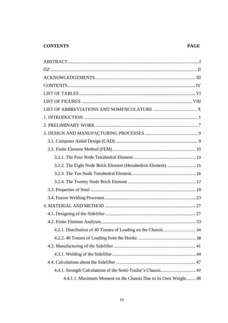
CONTENTS PAGE
ABSTRACT .................................................................................................................. I
ÖZ ............................................................................................................................... II
ACKNOWLEDGEMENTS ....................................................................................... III
CONTENTS ............................................................................................................... IV
LIST OF TABLES ..................................................................................................... VI
LIST OF FIGURES ................................................................................................ VIII
LIST OF ABBREVIATIONS AND NOMENCULATURE ...................................... X
1. INTRODUCTION ................................................................................................... 1
2. PRELIMINARY WORK ......................................................................................... 7
3. DESIGN AND MANUFACTURING PROCESSES .............................................. 9
3.1. Computer Aided Design (CAD) ........................................................................ 9
3.2. Finite Element Method (FEM) ........................................................................ 10
3.2.1. The Four Node Tetrahedral Element ........................................................... 13
3.2.2. The Eight Node Brick Element (Hexahedron Element) ........................... 15
3.2.3. The Ten Node Tetrahedral Element............................................................. 16
3.2.4. The Twenty Node Brick Element ................................................................ 17
3.3. Properties of Steel ........................................................................................... 18
3.4. Fusion Welding Processes ............................................................................... 23
4. MATERIAL AND METHOD ............................................................................... 27
4.1. Designing of the Sidelifter .............................................................................. 27
4.2. Finite Element Analyses .................................................................................. 33
4.2.1. Distribution of 40 Tonnes of Loading on the Chassis ............................... 34
4.2.2. 40 Tonnes of Loading from the Hooks ....................................................... 38
4.3. Manufacturing of the Sidelifter ....................................................................... 41
4.3.1. Welding of the Sidelifter ............................................................................... 44
4.4. Calculations about the Sidelifter ..................................................................... 47
4.4.1. Strength Calculations of the Semi-Trailer’s Chassis ................................. 47
4.4.1.1. Maximum Moment on the Chassis Due to its Own Weight ........ 48
V
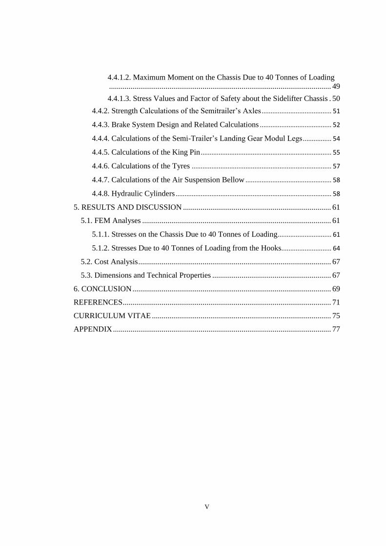
4.4.1.2. Maximum Moment on the Chassis Due to 40 Tonnes of Loading
.................................................................................................................. 49
4.4.1.3. Stress Values and Factor of Safety about the Sidelifter Chassis . 50
4.4.2. Strength Calculations of the Semitrailer’s Axles ....................................... 51
4.4.3. Brake System Design and Related Calculations ........................................ 52
4.4.4. Calculations of the Semi-Trailer’s Landing Gear Modul Legs ................ 54
4.4.5. Calculations of the King Pin ......................................................................... 55
4.4.6. Calculations of the Tyres .............................................................................. 57
4.4.7. Calculations of the Air Suspension Bellow ................................................ 58
4.4.8. Hydraulic Cylinders ....................................................................................... 58
5. RESULTS AND DISCUSSION ............................................................................ 61
5.1. FEM Analyses ................................................................................................. 61
5.1.1. Stresses on the Chassis Due to 40 Tonnes of Loading .............................. 61
5.1.2. Stresses Due to 40 Tonnes of Loading from the Hooks............................ 64
5.2. Cost Analysis ................................................................................................... 67
5.3. Dimensions and Technical Properties ............................................................. 67
6. CONCLUSION ...................................................................................................... 69
REFERENCES ........................................................................................................... 71
CURRICULUM VITAE ............................................................................................ 75
APPENDIX ................................................................................................................ 77
VI
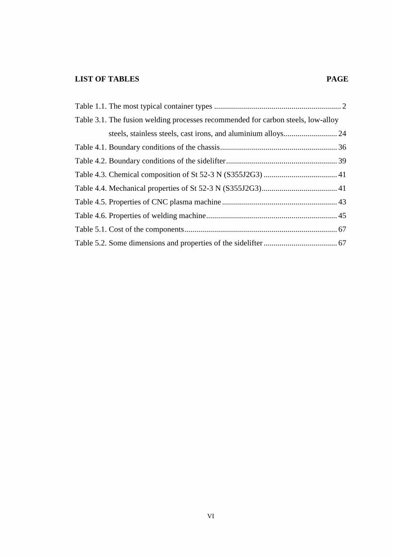
LIST OF TABLES PAGE
Table 1.1. The most typical container types ................................................................ 2
Table 3.1. The fusion welding processes recommended for carbon steels, low-alloy
steels, stainless steels, cast irons, and aluminium alloys........................... 24
Table 4.1. Boundary conditions of the chassis ........................................................... 36
Table 4.2. Boundary conditions of the sidelifter ........................................................ 39
Table 4.3. Chemical composition of St 52-3 N (S355J2G3) ..................................... 41
Table 4.4. Mechanical properties of St 52-3 N (S355J2G3) ...................................... 41
Table 4.5. Properties of CNC plasma machine .......................................................... 43
Table 4.6. Properties of welding machine .................................................................. 45
Table 5.1. Cost of the components ............................................................................. 67
Table 5.2. Some dimensions and properties of the sidelifter ..................................... 67

VII
VIII
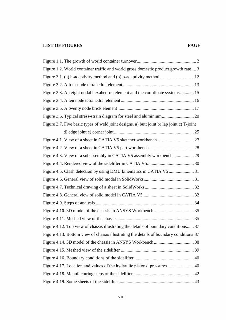
LIST OF FIGURES PAGE
Figure 1.1. The growth of world container turnover .................................................... 2
Figure 1.2. World container traffic and world gross domestic product growth rate .... 3
Figure 3.1. (a) h-adaptivity method and (b) p-adaptivity method .............................. 12
Figure 3.2. A four node tetrahedral element .............................................................. 13
Figure 3.3. An eight nodal hexahedron element and the coordinate systems ............ 15
Figure 3.4. A ten node tetrahedral element ................................................................ 16
Figure 3.5. A twenty node brick element ................................................................... 17
Figure 3.6. Typical stress-strain diagram for steel and aluminium ............................ 20
Figure 3.7. Five basic types of weld joint designs. a) butt joint b) lap joint c) T-joint
d) edge joint e) corner joint ...................................................................... 25
Figure 4.1. View of a sheet in CATIA V5 sketcher workbench ................................ 27
Figure 4.2. View of a sheet in CATIA V5 part workbench ....................................... 28
Figure 4.3. View of a subassembly in CATIA V5 assembly workbench .................. 29
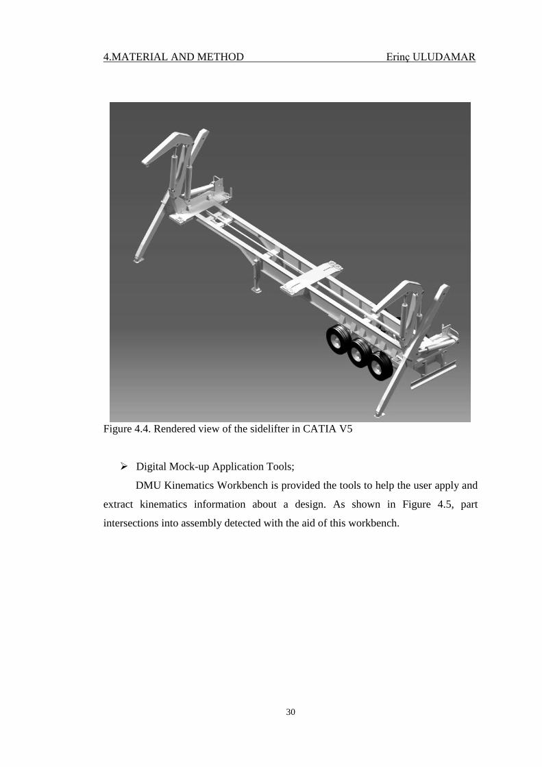
Figure 4.4. Rendered view of the sidelifter in CATIA V5......................................... 30
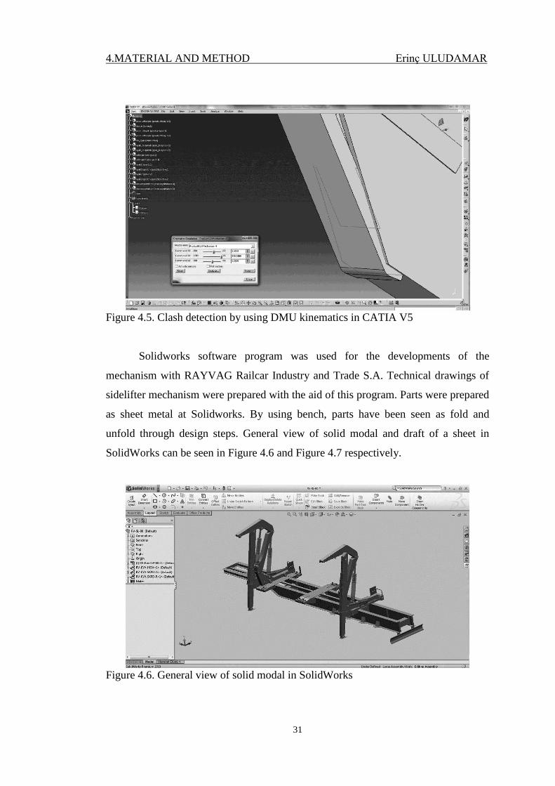
Figure 4.5. Clash detection by using DMU kinematics in CATIA V5 ...................... 31
Figure 4.6. General view of solid modal in SolidWorks............................................ 31
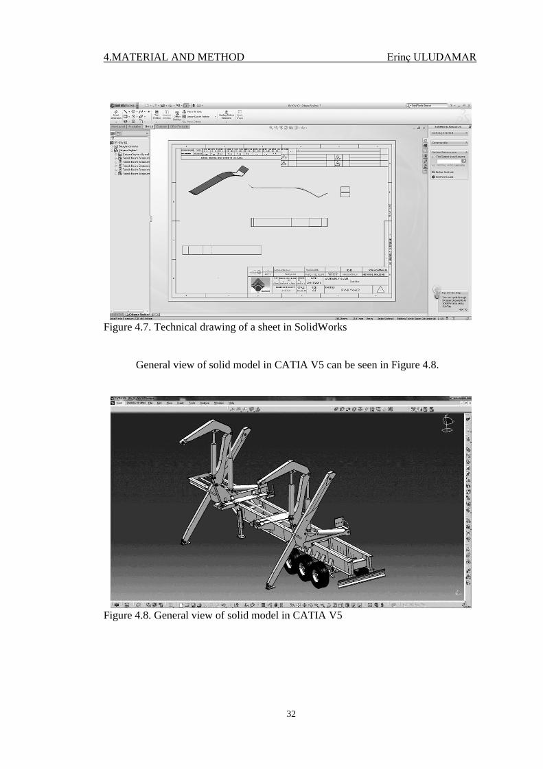
Figure 4.7. Technical drawing of a sheet in SolidWorks ........................................... 32
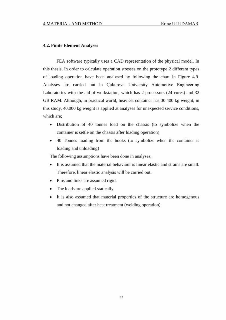
Figure 4.8. General view of solid model in CATIA V5............................................. 32
Figure 4.9. Steps of analysis ...................................................................................... 34
Figure 4.10. 3D model of the chassis in ANSYS Workbench ................................... 35
Figure 4.11. Meshed view of the chassis ................................................................... 35
Figure 4.12. Top view of chassis illustrating the details of boundary conditions ...... 37
Figure 4.13. Bottom view of chassis illustrating the details of boundary conditions 37
Figure 4.14. 3D model of the chassis in ANSYS Workbench ................................... 38
Figure 4.15. Meshed view of the sidelifter ................................................................ 39
Figure 4.16. Boundary conditions of the sidelifter .................................................... 40
Figure 4.17. Location and values of the hydraulic pistons’ pressures ....................... 40
Figure 4.18. Manufacturing steps of the sidelifter ..................................................... 42
Figure 4.19. Some sheets of the sidelifter .................................................................. 43
IX
Figure 4.20. CNC plasma machine that is used for cutting sheets ............................. 43
Figure 4.21. Gas–metal arc welding .......................................................................... 44
Figure 4.22. Welding machine that used for welding operations .............................. 45
Figure 4.23. Distortions in welded structures ............................................................ 45
Figure 4.24. View of a weld ....................................................................................... 46
Figure 4.25. View of I-profile .................................................................................... 47
Figure 4.26. Loads that are exerted on the chassis ..................................................... 48
Figure 4.27. Loads that are exerted on the chassis ..................................................... 49
Figure 4.28. Axles of the sidelifter............................................................................. 51
Figure 4.29. Loads that exerted on the axle ............................................................... 51
Figure 4.30. Terminology for long shoe drums brake ............................................... 52
Figure 4.31. Label of the landing gear modul legs that used at the sidelifter ............ 54
Figure 4.32. Reaction forces of the semitrailer’s legs ................................................ 54
Figure 4.33. Dimensions of king pin .......................................................................... 55
Figure 4.34. Tyres of the sidelifter ............................................................................. 57
Figure 4.35. CAD model of different sizes of hydraulic cylinders used for the
sidelifter .................................................................................................. 58
Figure 4.36. Hydraulic cylinders ................................................................................ 59
Figure 4.37. Project of the hydraulics which are used at the sidelifter ...................... 59
Figure 5.1. von-Mises stresses of the chassis ............................................................. 62
Figure 5.2. Distribution of normal stresses on the chassis under 40 tonnes load ...... 63
Figure 5.3. Structural errors on the chassis ................................................................ 63
Figure 5.4. von-Mises stresses and critical area under 40 tonnes load ...................... 65
Figure 5.5. The damage as a result of 30 tonnes loading ........................................... 65
Figure 5.6. Leaning of the boom under 20 tonnes load ............................................. 66
Figure 5.7. Deformation of the boom in FEM analysis under 40 tonnes load ........... 66
Figure 5.8. Technical drawing of the sidelifter as folded .......................................... 68
Figure 5.9. Technical drawing of the sidelifter as unfolded ...................................... 68
Figure 6.1. Prototype of the sidelifter ........................................................................ 70
X
LIST OF ABBREVIATIONS AND NOMENCULATURE
TEU : Twenty feet equivalent unit
PTO : Power take off
FEM : Finite element method
CAD : Computer aided design
CAM : Computer aided design
CATIA : Computer Aided Three-dimensional Interactive Application
CAE : Computer Aided Engineering
FEA : Finite element analysis
3D : Three dimensional
su : Tensile Strength
sy : Yield Strength
E : Modulus of Elasticity in Tension
sys : Yield strength in shear
sus : Ultimate strength in shear
ν : Poisson's Ratio
G : Modulus of Elasticity in Shear
OAW : Oxyacetylene welding
SMAW : Shielded metal arc welding
GTAW : Gas–tungsten arc welding
PAW : Plasma arc welding
GMAW : Gas–metal arc welding
FCAW : Flux-cored arc welding
SAW : Submerged arc welding
ESW : Electroslag welding
EBW : Electron beam welding
LBW : Laser beam welding
C : Carbon
Si : Silicon
Mn : Manganese
XI
P : Phosphorus
S : Sulphur
Nb : Niobium
Al : Aluminium
N : Nitrogen
Ar : Argon
He : Helium
CNC : Computer Numerical Control
MIG : Metal inert gas
1. INTRODUCTION Erinç ULUDAMAR
1
1. INTRODUCTION
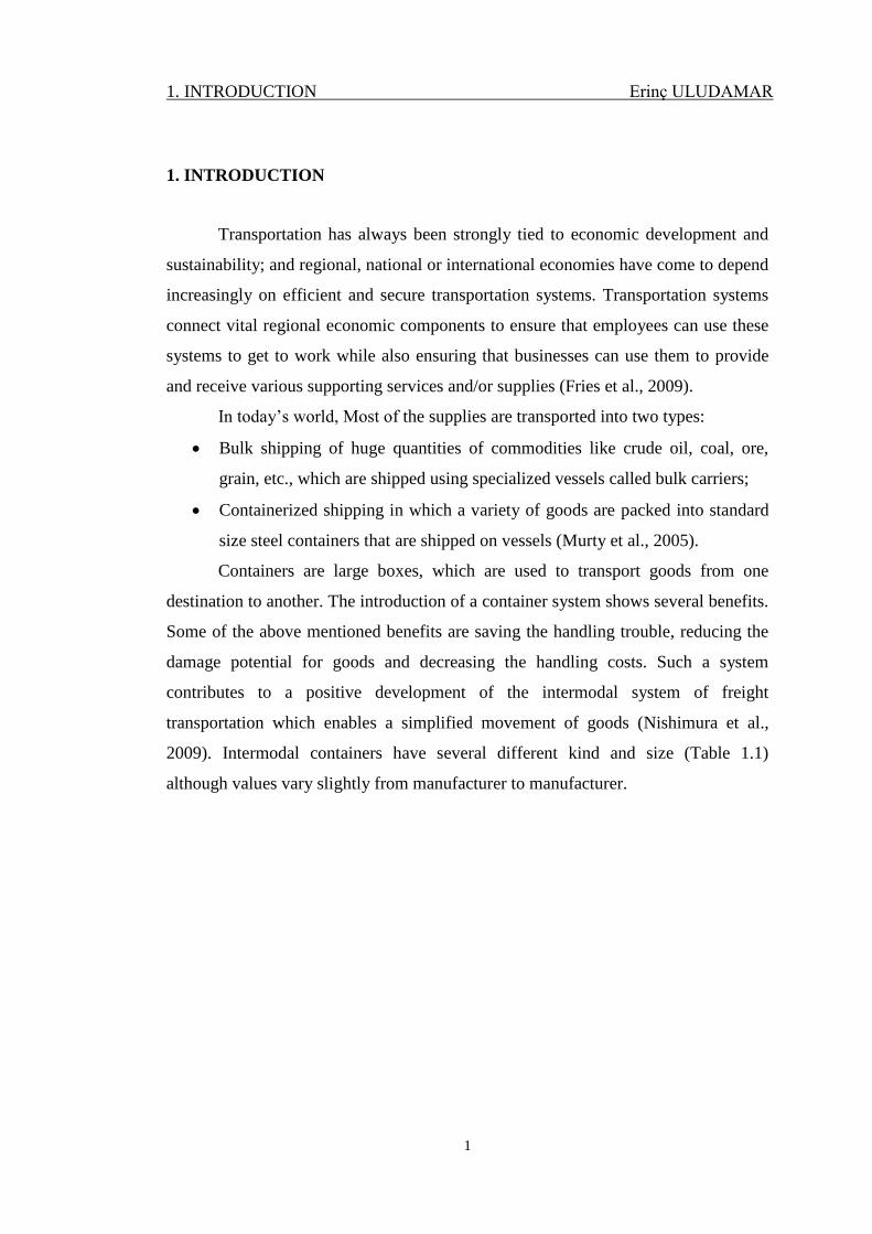
Transportation has always been strongly tied to economic development and
sustainability; and regional, national or international economies have come to depend
increasingly on efficient and secure transportation systems. Transportation systems
connect vital regional economic components to ensure that employees can use these
systems to get to work while also ensuring that businesses can use them to provide
and receive various supporting services and/or supplies (Fries et al., 2009).
In today’s world, Most of the supplies are transported into two types:
Bulk shipping of huge quantities of commodities like crude oil, coal, ore,
grain, etc., which are shipped using specialized vessels called bulk carriers;
Containerized shipping in which a variety of goods are packed into standard
size steel containers that are shipped on vessels (Murty et al., 2005).
Containers are large boxes, which are used to transport goods from one
destination to another. The introduction of a container system shows several benefits.
Some of the above mentioned benefits are saving the handling trouble, reducing the
damage potential for goods and decreasing the handling costs. Such a system
contributes to a positive development of the intermodal system of freight
transportation which enables a simplified movement of goods (Nishimura et al.,
2009). Intermodal containers have several different kind and size (Table 1.1)
although values vary slightly from manufacturer to manufacturer.
1. INTRODUCTION Erinç ULUDAMAR
2
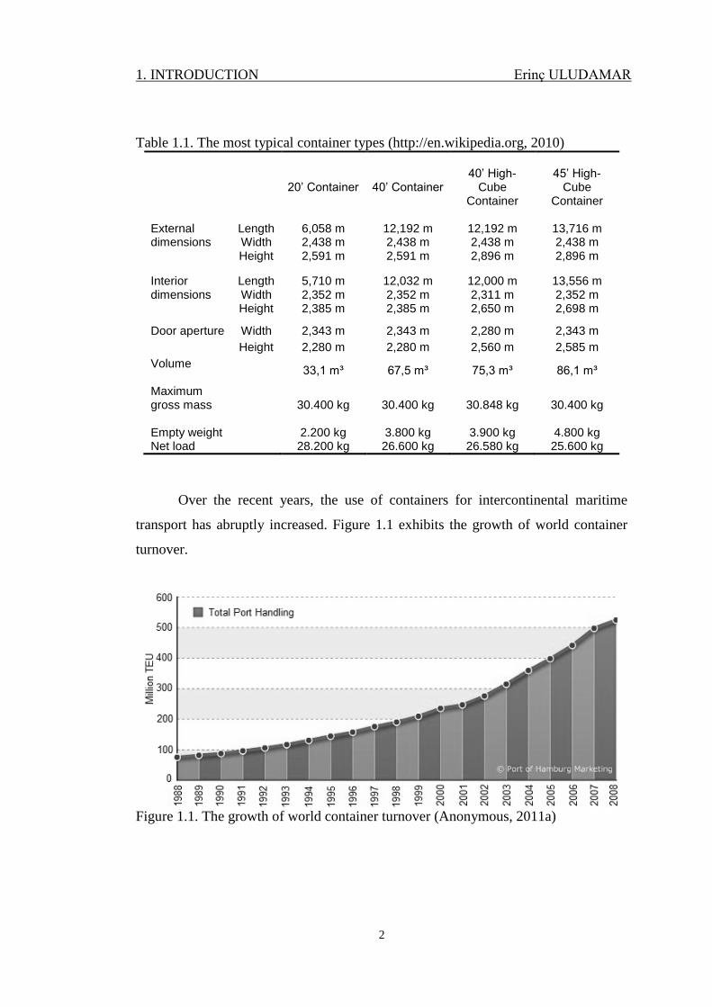
Table 1.1. The most typical container types (http://en.wikipedia.org, 2010)
20’ Container 40’ Container 40’ High-
Cube Container
45’ High-
Cube Container
External dimensions
Length 6,058 m 12,192 m 12,192 m 13,716 m Width 2,438 m 2,438 m 2,438 m 2,438 m Height 2,591 m 2,591 m 2,896 m 2,896 m
Interior dimensions
Length 5,710 m 12,032 m 12,000 m 13,556 m Width 2,352 m 2,352 m 2,311 m 2,352 m Height 2,385 m 2,385 m 2,650 m 2,698 m
Door aperture Width 2,343 m 2,343 m 2,280 m 2,343 m
Height 2,280 m 2,280 m 2,560 m 2,585 m
Volume
33,1 m³ 67,5 m³ 75,3 m³ 86,1 m³
Maximum gross mass
30.400 kg 30.400 kg 30.848 kg 30.400 kg
Empty weight 2.200 kg 3.800 kg 3.900 kg 4.800 kg Net load 28.200 kg 26.600 kg 26.580 kg 25.600 kg
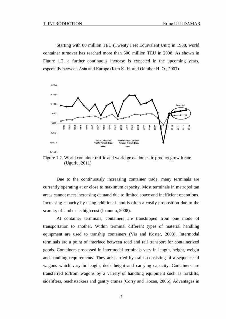
Over the recent years, the use of containers for intercontinental maritime
transport has abruptly increased. Figure 1.1 exhibits the growth of world container
turnover.
Figure 1.1. The growth of world container turnover (Anonymous, 2011a)
1. INTRODUCTION Erinç ULUDAMAR
3
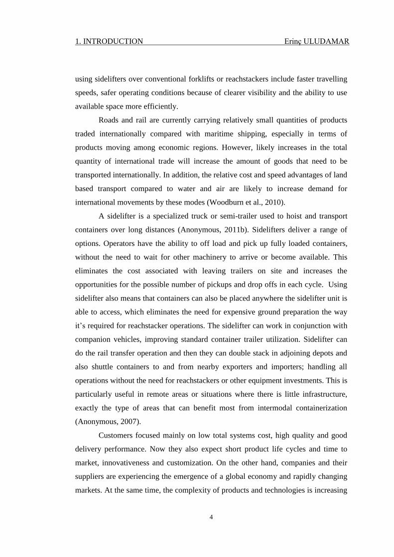
Starting with 80 million TEU (Twenty Feet Equivalent Unit) in 1988, world
container turnover has reached more than 500 million TEU in 2008. As shown in
Figure 1.2, a further continuous increase is expected in the upcoming years,
especially between Asia and Europe (Kim K. H. and Günther H. O., 2007).
Figure 1.2. World container traffic and world gross domestic product growth rate
(Ugurlu, 2011)
Due to the continuously increasing container trade, many terminals are
currently operating at or close to maximum capacity. Most terminals in metropolitan
areas cannot meet increasing demand due to limited space and inefficient operations.
Increasing capacity by using additional land is often a costly proposition due to the
scarcity of land or its high cost (Ioannou, 2008).
At container terminals, containers are transhipped from one mode of
transportation to another. Within terminal different types of material handling
equipment are used to tranship containers (Vis and Koster, 2003). Intermodal
terminals are a point of interface between road and rail transport for containerized
goods. Containers processed in intermodal terminals vary in length, height, weight
and handling requirements. They are carried by trains consisting of a sequence of
wagons which vary in length, deck height and carrying capacity. Containers are
transferred to/from wagons by a variety of handling equipment such as forklifts,
sidelifters, reachstackers and gantry cranes (Corry and Kozan, 2006). Advantages in
1. INTRODUCTION Erinç ULUDAMAR
4
using sidelifters over conventional forklifts or reachstackers include faster travelling
speeds, safer operating conditions because of clearer visibility and the ability to use
available space more efficiently.
Roads and rail are currently carrying relatively small quantities of products
traded internationally compared with maritime shipping, especially in terms of
products moving among economic regions. However, likely increases in the total
quantity of international trade will increase the amount of goods that need to be
transported internationally. In addition, the relative cost and speed advantages of land
based transport compared to water and air are likely to increase demand for
international movements by these modes (Woodburn et al., 2010).
A sidelifter is a specialized truck or semi-trailer used to hoist and transport
containers over long distances (Anonymous, 2011b). Sidelifters deliver a range of
options. Operators have the ability to off load and pick up fully loaded containers,
without the need to wait for other machinery to arrive or become available. This
eliminates the cost associated with leaving trailers on site and increases the
opportunities for the possible number of pickups and drop offs in each cycle. Using
sidelifter also means that containers can also be placed anywhere the sidelifter unit is
able to access, which eliminates the need for expensive ground preparation the way
it’s required for reachstacker operations. The sidelifter can work in conjunction with
companion vehicles, improving standard container trailer utilization. Sidelifter can
do the rail transfer operation and then they can double stack in adjoining depots and
also shuttle containers to and from nearby exporters and importers; handling all
operations without the need for reachstackers or other equipment investments. This is
particularly useful in remote areas or situations where there is little infrastructure,
exactly the type of areas that can benefit most from intermodal containerization
(Anonymous, 2007).
Customers focused mainly on low total systems cost, high quality and good
delivery performance. Now they also expect short product life cycles and time to
market, innovativeness and customization. On the other hand, companies and their
suppliers are experiencing the emergence of a global economy and rapidly changing
markets. At the same time, the complexity of products and technologies is increasing
1. INTRODUCTION Erinç ULUDAMAR
5
and their functionalities are expanding (Momme and Hvolby, 2002). The means by
which industries strengthen and enhance supply chain efficiency and decrease
logistics management costs are critical factors for economic development and serve
as reference models for transferring technologies to developing economies (Trappey
et al., in press).
Among many others, sidelifters are one of the imported equipment from
foreign countries. By developing and manufacturing this equipment in Turkey, the
amount of the imported machines is reduced and less unemployment can be obtained.
Sidelifters generally have the following attributes:
The hydraulically powered cranes lift the container (from the ground, loading
dock, another vehicle, railway wagon or from the top of another container
placed on the ground or other location) on and off the chassis. These cranes
are placed on top of the sidelifter chassis and they are normally able to travel
along the chassis being shifted by hydraulic cylinders or hydraulic motors in
order to load varying container lengths.
Typically the cranes are powered by a trailer mounted diesel engine or
gasoline engine, the cranes are sometimes powered via a Power Take Off
(PTO) from the truck or tractor.
Stabilizing legs of sidelifter are fitted with hydraulic legs which are necessary
to permit the lifting of up to 40 tonnes loads without tilting the vehicle. These
may be adjustable to assist operation on unlevel ground and facilitate greater
safety margins and load limits when stacking containers.
Chains are attached from the top of the cranes to the corner castings at the
base of the container during lifting operations. There is a special linking
device that when placed between two 6,096 m containers allow the user to
lock two 6,096 m containers together allowing the container lifter to lift them
as if they were a 12,192 m container.
The tractor or cab, which pulls the trailer and in some cases supplies power
through the PTO. This tractor or cab always supplies the compressed air for
the wheels' brakes of the sidelifter. Normally, the sidelifter cannot be
operated without being connected to the tractor. Even if the power pack is
1. INTRODUCTION Erinç ULUDAMAR
6
under the sidelifter, the tractor provides compressed air for the trailer brakes
and also additional stability for the lifting operation.
The chassis bears the weight of the container when loaded and also supports
the cranes.
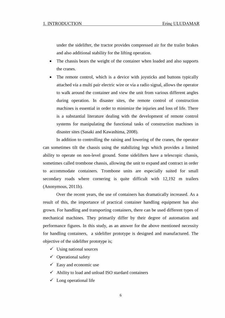
The remote control, which is a device with joysticks and buttons typically
attached via a multi pair electric wire or via a radio signal, allows the operator
to walk around the container and view the unit from various different angles
during operation. In disaster sites, the remote control of construction
machines is essential in order to minimize the injuries and loss of life. There
is a substantial literature dealing with the development of remote control
systems for manipulating the functional tasks of construction machines in
disaster sites (Sasaki and Kawashima, 2008).
In addition to controlling the raising and lowering of the cranes, the operator
can sometimes tilt the chassis using the stabilizing legs which provides a limited
ability to operate on non-level ground. Some sidelifters have a telescopic chassis,
sometimes called trombone chassis, allowing the unit to expand and contract in order
to accommodate containers. Trombone units are especially suited for small
secondary roads where cornering is quite difficult with 12,192 m trailers
(Anonymous, 2011b).
Over the recent years, the use of containers has dramatically increased. As a
result of this, the importance of practical container handling equipment has also
grown. For handling and transporting containers, there can be used different types of
mechanical machines. They primarily differ by their degree of automation and
performance figures. In this study, as an answer for the above mentioned necessity
for handling containers, a sidelifter prototype is designed and manufactured. The
objective of the sidelifter prototype is;
Using national sources
Operational safety
Easy and economic use
Ability to load and unload ISO stardard containers
Long operational life
2. PRELIMINARY WORK Erinç ULUDAMAR
7
2. PRELIMINARY WORK
The sidelifter was invented in the 1960s for military operations. Today, all
over the World, just 2 big companies are manufacturing sidelifters. In a containerized
world, there is an obvious demand for a loader which makes it possible to load at one
destination, carry and unload at other destination by itself. Also in the literature,
there is not presented study about sidelifters, but some studies show interested with
the moving machines such as backhoe-loader, bucket wheel excavator, excavator etc.
Karlinski et al. used finite element method to analyse protective structures for
construction and mining machine operators (Karlinski et al., 2008).
Rusinski et al. discussed designing problems of machines used in
underground mining and investigation of its reasons based on cracked boom of
underground mine machine. Numerical and experimental approaches were used in
order to achieve wider point of view of such accidents, which happens in this type of
machines. Numerical method used for the finite element method (Rusinski et al.,
2006).
Miralbes and Castejon presented a new methodology of calculation by means
of the FEM applied to crane jibs. This analysis has been carried out in terms of
strength, stiffness and for any type of crane jib such as telescopic crane, lattice crane,
closed beam crane, etc. The principal conclusions that are it has been developed a
methodology for the design, calculation and optimization of crane jibs for forklift
trucks, adapting the regulation UNE-58536 for mobile cranes (Miralbes and
Castejon, 2009).
Sasaki and Kawashima developed remote control of backhoe at construction
sites with a pneumatic robotic system. The system mainly consists of robot arm
module having 2 DOFs, a control box to make the system compact and a vision
system to help the task. The high portability was realized since the weight of the
system is only 40 kg. The remote control system was applied with two types of
backhoe, one small with bucket size of 0,025 m3 and another medium-sized with
0,28 m3. The remote control experiments were successfully conducted with support
of vision from the cameras. The remote control operations were well achieved at a
2. PRELIMINARY WORK Erinç ULUDAMAR
8
construction site with the medium sized backhoe. The working efficiency of the
remote operation was more than 50% compared with the direct operation. The
system herein provides an opportunity to improve safety (Sasaki and Kawashima,
2008).
Ghigliazza and Holmes described the derivation and analysis of equations
governing the Dynamics of a spherical pendulum with a horizontally moving
support, which model the behaviours of tower or ceiling mounted cranes with
rotating booms. The resulting two degree of freedom system is in general non-
integrable and appears to display chaotic dynamics. They focussed on the special
cases of a linearly translating suspension point and a suspension point in uniform
circular motion. In the former case, the system remains completely integrable,
although neither energy nor the Hamiltonian are conserved. In the second case the
Hamiltonian is conserved, but there is no analogue of angular momentum
conservation and while we are able to find steady coning motions and determine their
stability and bifurcations, we cannot give a complete global description of the
dynamics (Ghigliazza and Holmes, 2002).
3. DESIGN AND MANUFACTURING PROCESSES Erinç ULUDAMAR
9
3. DESIGN AND MANUFACTURING PROCESSES
In this study, CAD and FEM softwares are frequently used for the decision of
the design, material and joining process. In this chapter basic information about these
technologies are presented.
3.1. Computer Aided Design (CAD)
CAD/CAM products are one of the precious items for today’s companies
which are try to get bigger or survive in a harsh market competition. With the aid of
these kind of softwares, development process allowing improved quality, reduced
cost products to get to market faster.
Graphic interfaces are often used to help in the creation and manipulation of
the geometrical objects. Numerous Computer Aided Design (CAD) software
packages are used for engineering design which can produce files containing the
geometry of the designed engineering system. These files can usually be read in by
modelling software packages, which can significantly save time when creating the
geometry of the models. However, in many cases, complex objects read directly from
a CAD file may need to be modified and simplified before performing meshing or
discretization. CAD packages are incorporate modelling and simulation packages,
and these are useful for the rapid prototyping of new products (Liu and Quek, 2003).
Solid modelling systems usually provide an interface to one or more Finite
Element Analysis (FEA) programs and allow direct transfer of the model’s geometry
to the FEA package for stress, vibration, and heat transfer analysis. Some CAD
systems include a mesh generation feature which creates the FEA mesh
automatically before sending the data to the FEA software. This combination of tools
provides an extremely powerful means to obtain superior designs whose stresses are
more accurately known than would be possible by conventional analysis techniques
when the geometry is complex (Norton, 2006).
CATIA (Computer Aided Three-dimensional Interactive Application) is
multi-platform CAD/CAM/CAE commercial software developed by the French
3. DESIGN AND MANUFACTURING PROCESSES Erinç ULUDAMAR
10
company Dassault Systèmes and marketed worldwide by IBM. Written in the C++
programming language, CATIA is the cornerstone of the Dassault Systèmes product
lifecycle management software. The software was created in the late 1970s and early
1980s to develop Dassault's Mirage fighter jet, and then was adopted in the
aerospace, automotive, shipbuilding, and other industries (Anonymous, 2011a).
SolidWorks is a 3D mechanical CAD (computer aided design) program that
runs on Microsoft Windows and is being developed by Dassault Systèmes
SolidWorks Corporation. SolidWorks is currently used by over 1.3 million engineers
and designers at more than 130,000 companies worldwide.
SolidWorks application was first introduced in 1995. SolidWorks was
founded in 1993 by Jon Hirschtick, who recruited a team of engineers to build a
company that developed 3D CAD software that was easy to use, affordable and
available on the desktop and released its first product, SolidWorks 95, in 1995. In
1997 Dassault Systèmes, best known for its CATIA CAD software, acquired the
company and currently owns 100% of its shares (Anonymous, 2011b).
3.2. Finite Element Method (FEM)
The use of numerical methods such as FEA has been adopted in solving
complicated geometric problems, for which it is very difficult to achieve an
analytical solution. FEA is a technique for obtaining a solution to a complex
mechanics problem by dividing the problem domain into a collection of much
smaller and simpler domains (elements) where field variables can be interpolated
using shape functions. An overall approximated solution to the original problem is
determined based on variation principles. In other words, FEA is a method whereby,
instead of seeking a solution function for the entire domain, it formulates solution
functions for each finite element and combines them properly to obtain a solution to
the whole body. A mesh is needed in FEA to divide the whole domain into small
elements. The process of creating the mesh, elements, their respective nodes, and
defining boundary conditions is termed discretization of the problem domain (Geng
et al., 2008).
3. DESIGN AND MANUFACTURING PROCESSES Erinç ULUDAMAR
11
A three-dimensional (3D) solid element can be considered to be the most
general of all solid finite elements because all the field variables are dependent of x,
y and z. A 3D solid can also have any arbitrary shape, material properties and
boundary conditions in space. As such, there are altogether six possible stress
components, three normal and three shear, that need to be taken into consideration.
Typically, a 3D solid element can be a tetrahedron or hexahedron in shape with
either flat or curved surfaces. Each node of the element will have three translational
degrees of freedom. The element can thus deform in all three directions in space. The
elements are interconnected at so called nodes (Liu and Quek, 2003).
Over the past 20-30 years finite element analysis (FEA) has evolved hand in
hand with the ever increasing hardware capabilities. Even with fully automatic mesh
generators, there are many cases where the solution time can be less than the
meshing time. The solution stage is predominantly batch oriented with little or no
user interaction required, while the model preparation and meshing stage is still
largely interactive. The demands placed on today's industrial automatic mesh
generators are as diverse as they are great. The following is a list of some of the most
important requirements on industrial meshing:
1. Basic Functionality;
2. Robustness/Reliability/Dependability;
3. Mesh Quality
4. Speed;
5. Minimal Required User Interaction:
6. Controllability
While all of these are important, when evaluating algorithms and overall meshing
schemes to address this list, these requirements are often competing and a balance
must be struck that best meets the user's requirements (Canann et al., 1997). Mesh
generation is one of the most critical aspects of engineering simulation. Too many
cells may result in long solver runs and too few many result in inaccurate results.
After an FE solution is obtained, its accuracy should be checked.
3. DESIGN AND MANUFACTURING PROCESSES Erinç ULUDAMAR
12
Two factors determine the accuracy of a solution.
1. Continuity of variables across element borders
2. Magnitude of numerical error
The accuracy depends on the number of degrees of freedom. The methods to increase
the accuracy are:
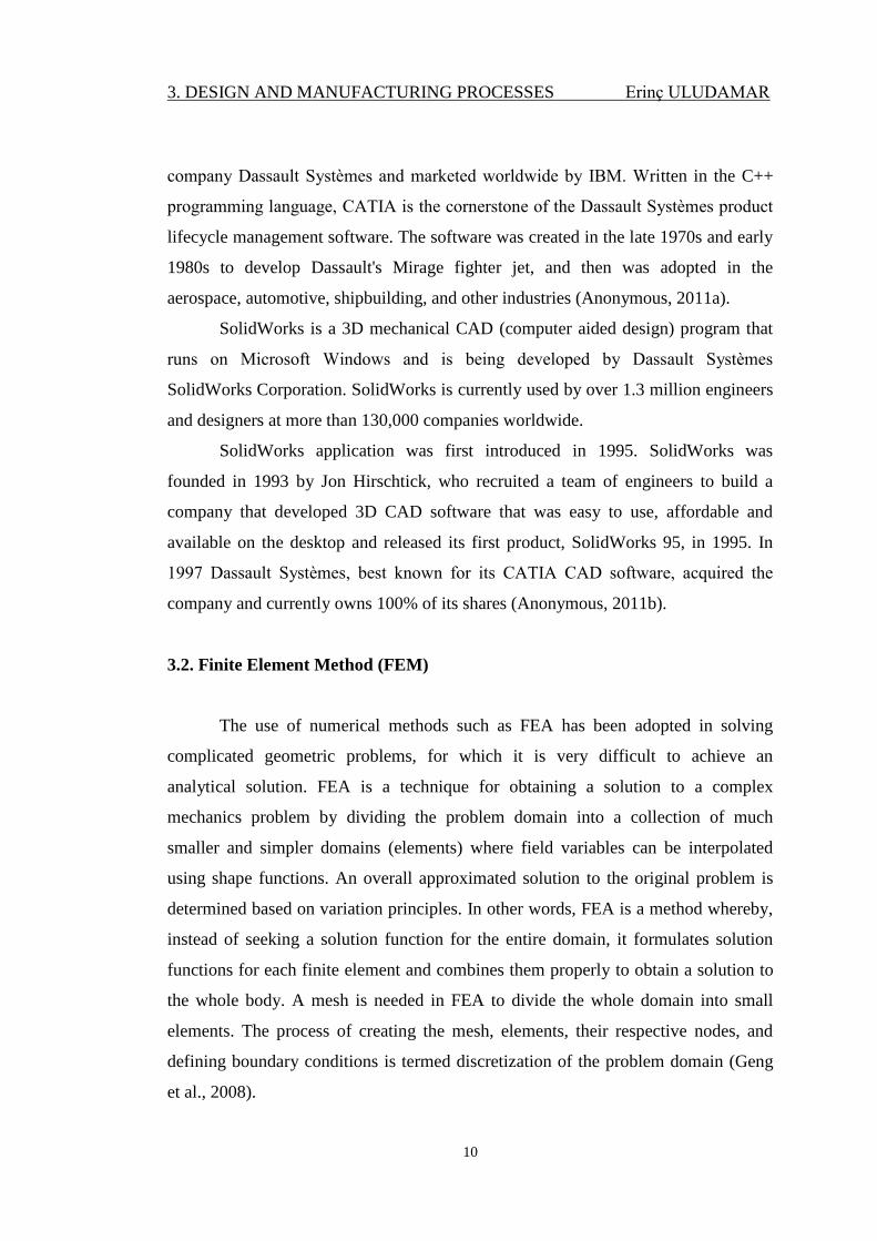
1. The mesh is locally refined by reducing the size of elements, while their
shape functions, i.e., the interpolating polynomials, stay unchanged (h–method). The
number of elements and nodes is increased, enlarging the number of degrees of
freedom. Property h, shown in Figure 3.1, denotes a characteristic dimension of the
element.
2. The number of degrees of freedom is increased by adding mid-side nodes
without changing the element size. The order of shape functions is increased.
3. The number of degrees of freedom is increased by adding displacement
derivatives at the nodes while number of nodes and the shape and size of elements
remain the same (p–method, shown in Figure 3.1). The order of shape functions is
increased, so derived shape functions become hierarchical functions (Zahavi and
Barlam, 2001).
Figure 3.1. (a) h-adaptivity method and (b) p-adaptivity method (Zahavi and Barlam,
2001)
3. DESIGN AND MANUFACTURING PROCESSES Erinç ULUDAMAR
13
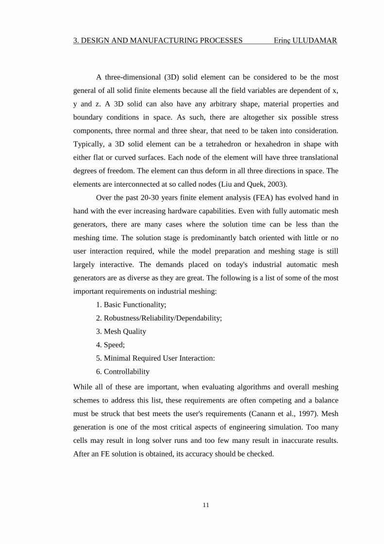
3.2.1. The Four Node Tetrahedral Element
The four node tetrahedral element (shown in Figure 3.2) is the simplest three
dimensional elements used in the analysis of solid mechanics problems. This element
has four nodes with each node having three translational degrees of freedom in the
nodal x-y-z directions (Moaveni, 2008).
Figure 3.2. A four node tetrahedral element (Liu and Quek, 2003)
The displacement field represented by the following equations:
u = C11 + C12X + C13Y + C14Z
v = C21 + C22 X + C23Y + C24Z (3.1.)
w = C31 + C32X + C33Y + C34Z
Considering the nodal displacements, the following conditions must be satisfied
u= uI at X = XI Y = YI Z = ZI
u= uJ at X = XJ Y = YJ Z = ZJ (3.2.)
u= uK at X = XK Y = YK Z = ZK
u= uL at X = XL Y = YL Z = ZL
3. DESIGN AND MANUFACTURING PROCESSES Erinç ULUDAMAR
14
Similarly, other following must be satisfied
v = vI at X = XI Y = YI Z = ZI (3.3.)
. . . . .
Substitution of respective nodal values into Eq. (1) results in 12 equations and 12
unknowns
uI = C11 + C12XI + C13YI + C14ZI
uJ = C11 + C12 XJ + C13YJ + C14ZJ (3.4.)
.
.
wL = C31 + C32XL + C33YL + C34ZL
Solving for the unknown C-coefficients, substituting the results back into Eq. (1) and
regrouping the parameters
u = S1uI + S2uJ + S3uK + S4uL
v = S1vI + S2vJ + S3vK + S4vL (3.5.)
w = S1wI + S2wJ + S3wK + S4wL
The shape functions are;
S1 = (aI + bIX + cIY + dIZ) / 6V
S2 = (aJ + bJX + cJY + dJZ) / 6V (3.6.)
S3 = (aK + bKX + cKY + dKZ) / 6V
S4 = (aL + bLX + cLY + dLZ) / 6V
3. DESIGN AND MANUFACTURING PROCESSES Erinç ULUDAMAR
15
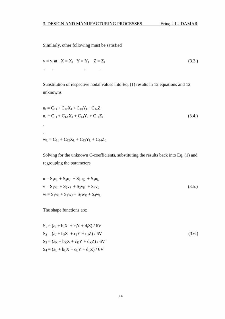
3.2.2. The Eight Node Brick Element (Hexahedron Element)
The eight node brick element (shown in Figure 3.3) is a simple three
dimensional element used in the analysis of solid mechanics problems. Each of the
eight nodes of this element has three translational degrees of freedom in the nodal x-
y-z directions (Moaveni, 2008).
Figure 3.3. An eight nodal hexahedron element and the coordinate systems (Liu and
Quek, 2003)
u = (uI (1 - s)(1 - t)(1 - r) + uJ (1 + s)(1 - t)(1 - r)) / 8
+ (uK (1 + s)(1 + t)(1 - r) + uL (1 - s)(1 + t)(1 - r)) / 8
+ (uM (1 - s)(1 - t)(1 + r) + uN (1 + s)(1 - t)(1 + r)) / 8
+ (uO (1 + s)(1 + t)(1 + r) + up (1 - s)(1 + t)(1 + r)) / 8
v = (vI (1 - s)(1 - t)(1 - r) + vJ (1 + s)(1 - t)(1 - r)) / 8
+ (vK (1 + s)(1 + t)(1 - r) + vL (1 - s)(1 + t)(1 - r)) / 8 (3.7.)
+ (vM (1 - s)(1 - t)(1 + r) + vN (1 + s)(1 - t)(1 + r)) / 8
+ (vO (1 + s)(1 + t)(1 + r) + vp (1 - s)(1 + t)(1 + r)) / 8
w = (wI (1 - s)(1 - t)(1 - r) + wJ (1 + s)(1 - t)(1 - r)) / 8
+ (wK (1 + s)(1 + t)(1 - r) + wL (1 - s)(1 + t)(1 - r)) / 8
+ (wM (1 - s)(1 - t)(1 + r) + wN (1 + s)(1 - t)(1 + r)) / 8
+ (wO (1 + s)(1 + t)(1 + r) + wp (1 - s)(1 + t)(1 + r)) / 8
3. DESIGN AND MANUFACTURING PROCESSES Erinç ULUDAMAR
16
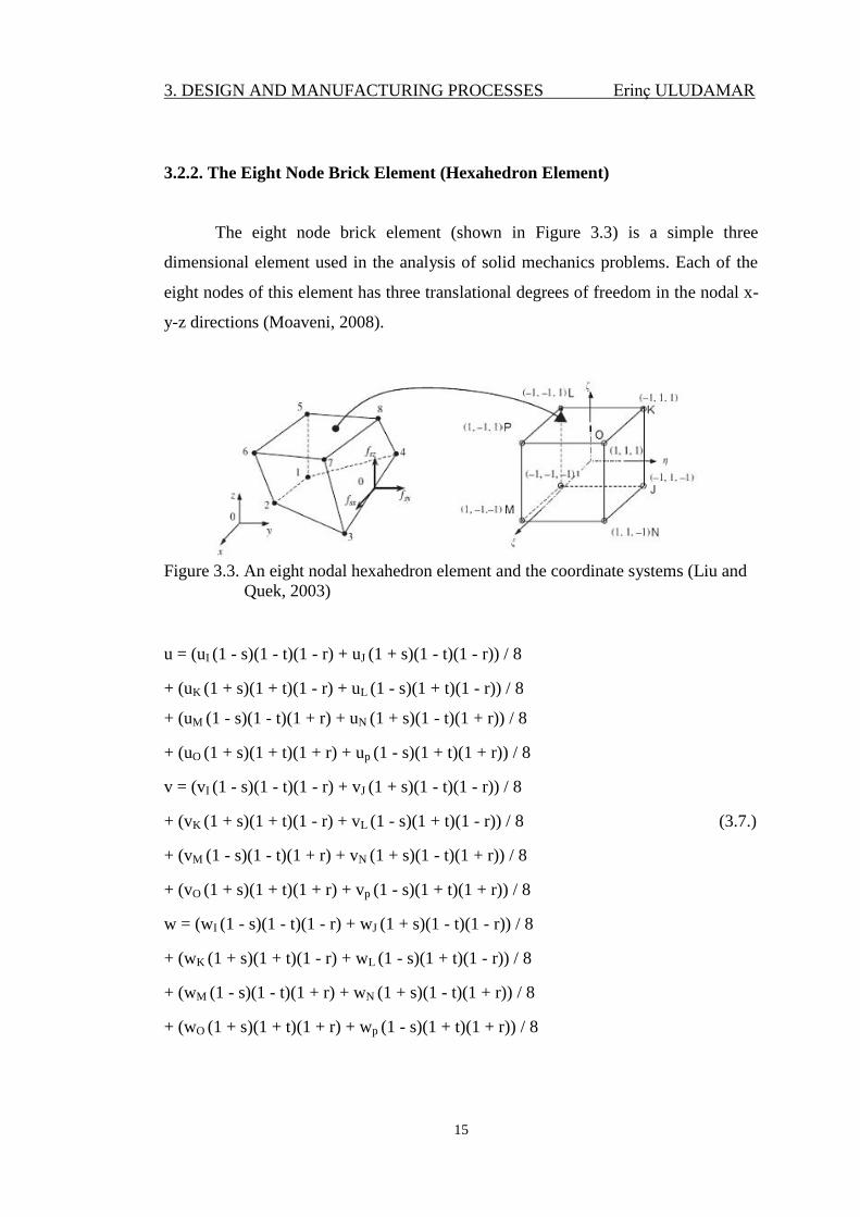
3.2.3. The Ten Node Tetrahedral Element
The ten node tetrahedral element (shown in Figure 3.4) is a higher order
version of the three dimensional linear tetrahedral element. When compared to the
four node tetrahedral element, the ten node tetrahedral element is better suited for
and more accurate in modelling problems with curved boundaries (Moaveni, 2008).
Figure 3.4. A ten node tetrahedral element (Liu and Quek, 2003)
u = uI(2S1-1)S1 + uJ(2S2 – 1)S2 + uK(2S3-1)S3 + uL(2S4 – 1)S4
+ 4(uMS1S2 + uNS2S3 + uOS1S3 + uPS1S4 + uQS2S4 + uRS3S4)
v = vI(2S1-1)S1 + vJ(2S2 – 1)S2 + vK(2S3-1)S3 + vL(2S4 – 1)S4
+ 4(vMS1S2 + vNS2S3 + vOS1S3 + vPS1S4 + vQS2S4 + vRS3S4) (3.8.)
w = wI(2S1-1)S1 + wJ(2S2 – 1)S2 + wK(2S3-1)S3 + wL(2S4 – 1)S4
+ 4(wMS1S2 + wNS2S3 + wOS1S3 + wPS1S4 + wQS2S4 + wRS3S4)
3. DESIGN AND MANUFACTURING PROCESSES Erinç ULUDAMAR
17
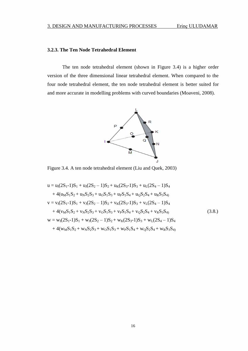
3.2.4. The Twenty Node Brick Element
The twenty node brick (shown in Figure 3.5) is a higher order version of the
three dimensional eight node brick element. This element is more capable and more
accurate for modelling problems with curved boundaries than the eight node brick
element (Moaveni, 2008).
Figure 3.5. A twenty node brick element (Liu and Quek, 2003)
u = (uI (1 - s)(1 - t)(1 - r)(- s – t – r - 2) + uJ (1 + s)(1 - t)(1 - r)(s – t – r - 2))/8
+ (uK (1 + s)(1 + t)(1 - r)(s + t – r - 2) + uL (1 - s)(1 + t)(1 - r)(- s + t – r - 2))/8
+ (uM (1 - s)(1 - t)(1 + r)(- s – t + r - 2) + uJ (1 + s)(1 - t)(1 + r)(s – t + r - 2))/8
+ (uO (1 + s)(1 + t)(1 + r)(s + t + r - 2) + uP (1 - s)(1 + t)(1 + r)(- s + t + r - 2))/8
+ (uQ(1 - s2)(1 - t)(1 – r) + uR(1 + s)(1 - t
2)(1 - r))/4
+ (uS(1 - s2)(1 + t)(1 – r) + uT(1 - s)(1 - t
2)(1 - r))/4 (3.9.)
+ (uU(1 - s2)(1 - t)(1 + r) + uV(1 + s)(1 - t
2)(1 + r))/4
+ (uW(1 - s2)(1 + t)(1 + r) + uX(1 - s)(1 - t
2)(1 + r))/4
+ (uY(1 - s)(1 - t)(1 – r2) + uZ(1 + s)(1 - t)(1 – r
2))/4
+ (uA(1 + s)(1 + t)(1 – r2) + uB(1 - s)(1 + t)(1 – r
2))/4
The v- and w- components of the displacement are similar to the u-component.
3. DESIGN AND MANUFACTURING PROCESSES Erinç ULUDAMAR
18
3.3. Properties of Steel
Steel is an efficient material for structural purposes because of its good
strength to weight ratio. Steel can be supplied with strength levels from about
250N/mm2 up to about 2000N/mm
2 for common structural applications, although the
strength requirements may limit the product form. The major advantage of steel is its
high strength relative to the strengths of the other common structural materials:
wood, masonry, and concrete (Davison and Graham, 2003). Unlike masonry and
concrete, which are weak in tension, steel is strong in both tension and compression.
Because of its high strength, structural steel is widely used in construction. The
tallest and longest span structures are predominantly steel (Rokach, 1991).
Steel derives its mechanical properties from a combination of chemical
composition, heat treatment and manufacturing processes. While the major
constituent of steel is always iron the addition of very small quantities of other
elements can have a marked effect upon the type and properties of steel. These
elements also produce a different response when the material is subjected to heat
treatments involving cooling at a prescribed rate from a particular peak temperature.
The manufacturing process may involve combinations of heat treatment and
mechanical working which are of critical importance in understanding the
subsequent performance of steels. The effects of chemical composition and heat
treatment on the metallurgy and properties of steels are to recognize that the
properties depend upon the following factors:
1. Microstructure
2. Grain size
3. Non-metallic inclusions
4. Precipitates within grains or at grain boundaries
5. The presence of absorbed or dissolved gases.
Steel is basically iron with the addition of small amounts of carbon up to a
maximum of 1.67% by weight, and other elements added to provide particular
mechanical properties. Above 1.67% carbon the material generally takes the form of
cast iron. As the carbon level is increased, the effect is to raise the strength level, but
3. DESIGN AND MANUFACTURING PROCESSES Erinç ULUDAMAR
19
reduce the ductility and make the material more sensitive to heat treatment. The
cheapest and simplest form is therefore a plain carbon steel commonly supplied for
the steel reinforcement in reinforced concrete structures, for wire ropes, for some
general engineering applications in the form of bars or rods, and for some sheet/strip
applications. However, plain carbon steels at medium to high carbon levels give rise
to problems where subsequent fabrication/manufacturing takes place, particularly
where welding is involved, and more versatility can be obtained by keeping carbon
to a relatively low level and adding other elements in small amounts. When
combined with appropriate heat treatments, addition of these other elements produces
higher strength while retaining good ductility, fracture toughness, and weldability, or
the development of improved hot strength, or improved corrosion resistance. The
retention of good fracture toughness with increased strength is particularly important
for thick sections, and for service applications at low temperatures where brittle
fracture may be a problem. Hot strength is important for service applications at high
temperatures such as pressure vessels and piping in the power generation and
chemical process plant industries. Corrosion-resistance is important for any
structures exposed to the environment, particularly for structures immersed in sea
water. Weathering grades of steel are designed to develop a tight adherent oxide
layer which slows down and stifles continuing corrosion under normal atmospheric
exposure of alternate wet and dry conditions. Stainless steels are designed to have a
protective oxide surface layer which reforms if any damage takes place to the
surface, and these steels are therefore designed not to corrode under oxidizing
conditions. Stainless steels find particular application in the chemical industry
(Davison and Graham, 2003).
Mechanical properties should be taken in consideration for the material
selection (Figure 3.6), these are;
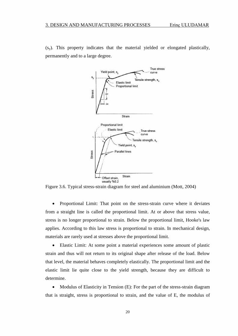
Tensile Strength (su): The peak of the stress-strain curve is called as ultimate
tensile strength (su) or simply the tensile strength. At this point during the test, the
highest apparent stress on a test bar of the material is measured.
Yield Strength (sy): That portion of the stress-strain diagram where there is a
large increase in strain with little or no increase in stress is called the yield strength
3. DESIGN AND MANUFACTURING PROCESSES Erinç ULUDAMAR
20
(sy). This property indicates that the material yielded or elongated plastically,
permanently and to a large degree.
Figure 3.6. Typical stress-strain diagram for steel and aluminium (Mott, 2004)
Proportional Limit: That point on the stress-strain curve where it deviates
from a straight line is called the proportional limit. At or above that stress value,
stress is no longer proportional to strain. Below the proportional limit, Hooke's law
applies. According to this law stress is proportional to strain. In mechanical design,
materials are rarely used at stresses above the proportional limit.
Elastic Limit: At some point a material experiences some amount of plastic
strain and thus will not return to its original shape after release of the load. Below
that level, the material behaves completely elastically. The proportional limit and the
elastic limit lie quite close to the yield strength, because they are difficult to
determine.
Modulus of Elasticity in Tension (E): For the part of the stress-strain diagram
that is straight, stress is proportional to strain, and the value of E, the modulus of
3. DESIGN AND MANUFACTURING PROCESSES Erinç ULUDAMAR
21
elasticity is the constant of proportionality. The modulus of elasticity indicates the
stiffness of the material or its resistance to deformation.
Ductility and Percent Elongation: Ductility is the degree to which a material
will deform before ultimate fracture. The opposite of ductility is brittleness. When
ductile materials are used in machine members, impending failure is detected easily
and sudden failure is unlikely. Also, ductile materials normally resist the repeated
loads on machine elements better than brittle materials. The usual measure of
ductility is the percent elongation of the material after fracture in a standard tensile
test.
Shear Strength (sys and sus): Both the yield strength and the ultimate strength
in shear (sys and sus, respectively) are important properties of materials. The
following estimates are generally used;
sys = sy/2 = 0,50*sy = Yield strength in shear (3.10.)
sus = 0,75*su = Ultimate strength in shear (3.11.)
Poisson's Ratio (ν): When a material is subjected to a tensile strain, there is a
simultaneous shortening of the cross-sectional dimensions perpendicular to the
direction of the tensile strain. The ratio of the shortening strain to the tensile strain is
called Poisson's ratio.
Modulus of Elasticity in Shear (G): The modulus of elasticity in shear (G) is
the ratio of shearing stress to shearing strain. This property indicates material's
stiffness under shear loading (Mott, 2004).
Hardness: Hardness is the property of a metal, which gives it the ability to
resist being permanently deformed (bent, broken, or have its shape changed), when a
load is applied. The greater the hardness of the metal, the greater resistance it has to
deformation.
Machinability: Machinability is related to the ease with which a material can
be machined to a good surface finish with reasonable tool life. Production rates are
directly affected by machinability (Mott, 2004).
3. DESIGN AND MANUFACTURING PROCESSES Erinç ULUDAMAR
22
Toughness and Impact Resistance: The ability per unit volume without
fracture of a material to absorb energy is called as toughness, also called as modulus
of toughness. It is equal to the area under the stress-strain curve up to the fracture
point.
The stress-strain test is done at very low, controlled strain rates, allowing the
material to accommodate itself to the changing load. If the load suddenly applied, the
energy absorption capacity of the material becomes important. The energy in the
differential element is its strain energy density, or the area under the stress-strain
curve at any particular strain (Norton, 2006).
0
0 dU (3.12.)
Fatigue Strength and Endurance Strength: Parts subjected to repeated applications of
loads or to stress conditions that vary with time over several thousands or millions of
cycles fail because of the phenomenon of fatigue. Materials are tested under
controlled cyclic loading to determine their ability to resist such repeated loads. The
resulting data are reported as the fatigue strength, also called the endurance strength
of the material.
Creep: When materials are subjected to high loads continuously, they may
experience progressive elongation over time. This property should be considered for
metals operating at high temperatures.
3. DESIGN AND MANUFACTURING PROCESSES Erinç ULUDAMAR
23
3.4. Fusion Welding Processes
Fusion welding is a joining process that uses fusion of the base metal to make
the weld. The three major types of fusion welding processes are as follows:
Gas welding:
Oxyacetylene welding (OAW)
Arc welding:
Shielded metal arc welding (SMAW)
Gas–tungsten arc welding (GTAW)
Plasma arc welding (PAW)
Gas–metal arc welding (GMAW)
Flux-cored arc welding (FCAW)
Submerged arc welding (SAW)
Electroslag welding (ESW)
High-energy beam welding:
Electron beam welding (EBW)
Laser beam welding (LBW)
Since there is no arc involved in the electroslag welding process, it is not
exactly an arc welding process. For convenience of discussion, it is grouped with arc
welding processes.
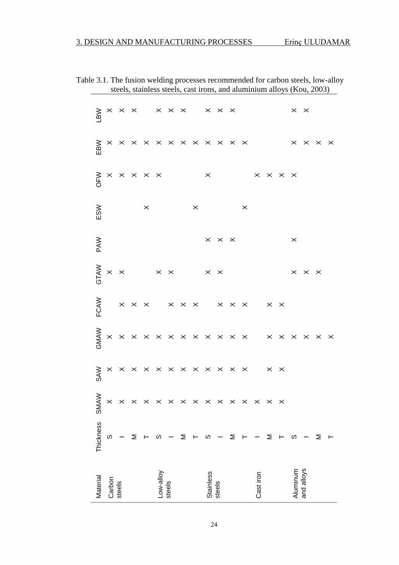
Table 3.1 shows the fusion welding processes recommended for carbon
steels, low-alloy steels, stainless steels, cast irons, and aluminium alloys (Process
code: SMAW, shielded metal arc welding; SAW, submerged arc welding; GMAW,
gas–metal arc welding; FCAW, flux-cored arc welding; GTAW, gas–tungsten arc
welding; PAW, plasma arc welding; ESW, electroslag welding; OFW, oxyfuel gas
welding; EBW, electron beam welding; LBW, laser beam welding. b Abbreviations:
S, sheet, up to 3mm (1/8 in.); I, intermediate, 3–6mm (1/8–1/4 in.); M, medium, 6–
19mm (1/4–3/4 in.); T, thick, 19mm (3/4 in.) and up; X, recommended).
3. DESIGN AND MANUFACTURING PROCESSES Erinç ULUDAMAR
24
Table 3.1. The fusion welding processes recommended for carbon steels, low-alloy
steels, stainless steels, cast irons, and aluminium alloys (Kou, 2003) LB
W
X
X
X X
X
X X
X
X X
X
EB
W
X
X
X
X
X
X
X
X
X
X
X
X X
X
X
X
OF
W
X
X
X
X
X X X
X
X
X
ES
W X X X
PA
W X
X
X X
GT
AW
X
X X
X X
X X
X
X
FC
AW
X
X
X X
X
X X
X
X X
X
GM
AW
X
X
X
X
X
X
X
X
X
X
X
X X
X
X
X
X
X
SA
W
X
X
X
X
X
X
X
X
X
X
X
X X
X
SM
AW
X
X
X
X
X
X
X
X
X
X
X
X
X
X
X
Thic
kness
S
I M
T
S
I M
T
S
I M
T I M
T
S
I M
T
Mate
rial
Carb
on
ste
els
Low
-allo
y
ste
els
Sta
inle
ss
ste
els
Cast iron
Alu
min
um
and a
lloys
3. DESIGN AND MANUFACTURING PROCESSES Erinç ULUDAMAR
25
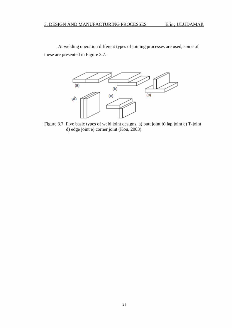
At welding operation different types of joining processes are used, some of
these are presented in Figure 3.7.
Figure 3.7. Five basic types of weld joint designs. a) butt joint b) lap joint c) T-joint
d) edge joint e) corner joint (Kou, 2003)
3. DESIGN AND MANUFACTURING PROCESSES Erinç ULUDAMAR
26
4.MATERIAL AND METHOD Erinç ULUDAMAR
27
4. MATERIAL AND METHOD
4.1. Designing of the Sidelifter
In this study, at design steps, CATIA V5 software program was used for the
development of the mechanism within Çukurova University Automotive Engineering
Laboratories. During the design steps different modules and workbenches of CATIA
V5 software was used, these are:
Mechanical Design Application Tools;
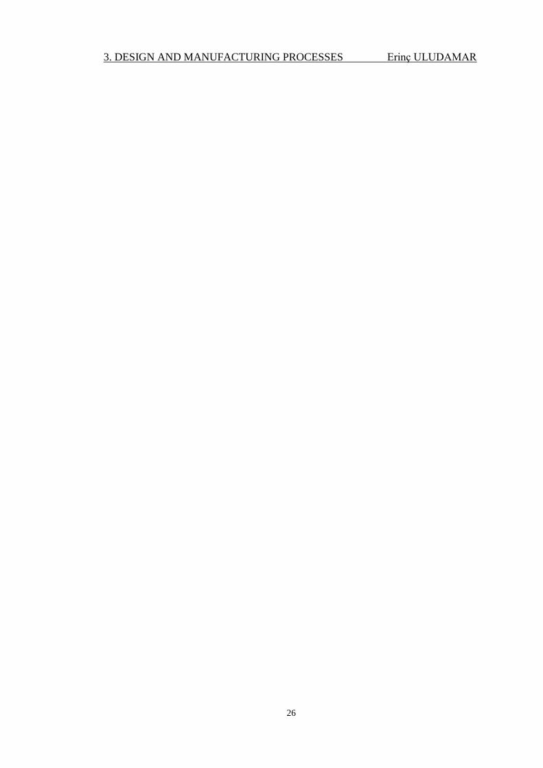
Sketcher Workbench is used for drawing sketches of the solid model (Figure
4.1).
Figure 4.1. View of a sheet in CATIA V5 sketcher workbench
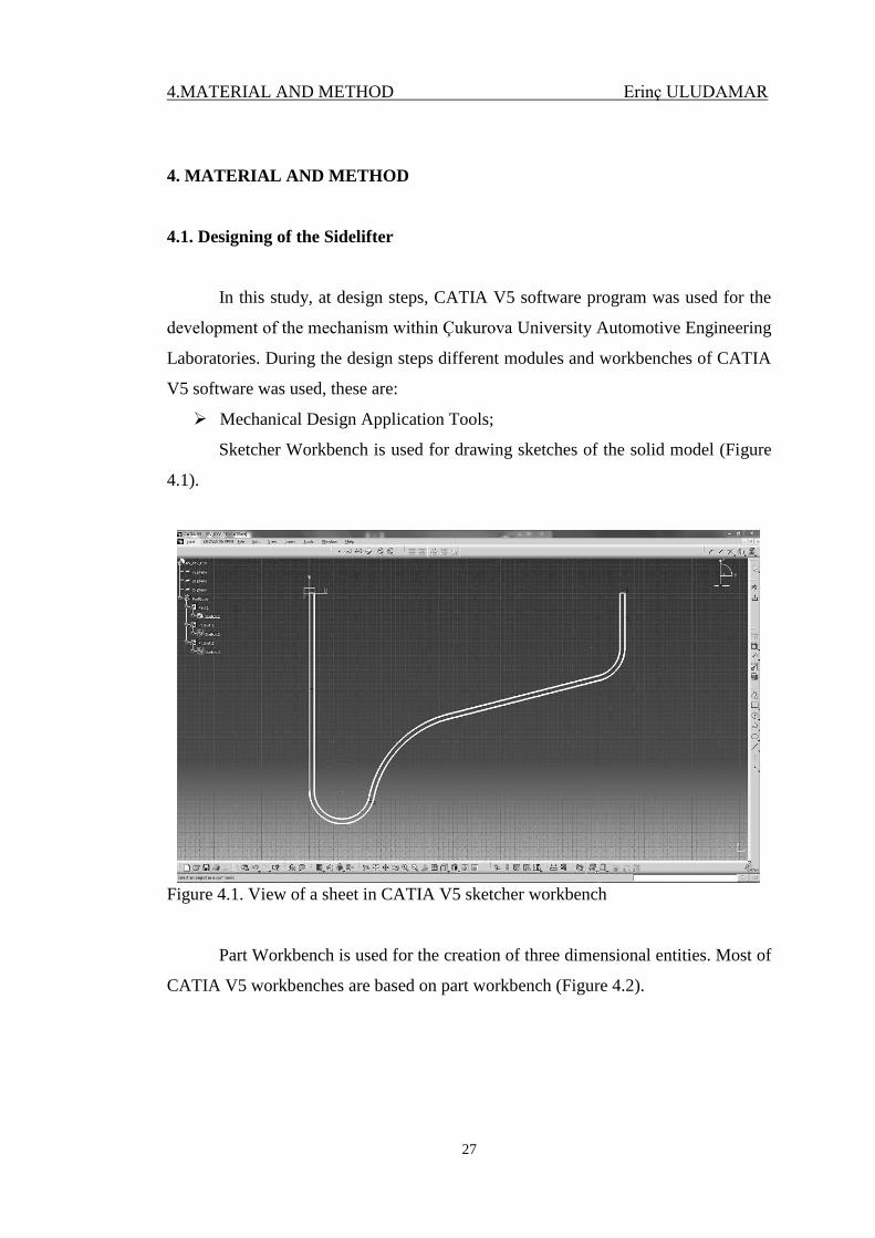
Part Workbench is used for the creation of three dimensional entities. Most of
CATIA V5 workbenches are based on part workbench (Figure 4.2).
4.MATERIAL AND METHOD Erinç ULUDAMAR
28
Figure 4.2. View of a sheet in CATIA V5 part workbench
Assembly modelling is used for creating designs that consist of two or more
components assembled together at their respective work positions. The components
are brought together and assembled in Assembly Design workbench by applying
suitable parametric assembly constraints to them. The assembly constraints allow
restricting the degrees of freedom of components on their respective work positions
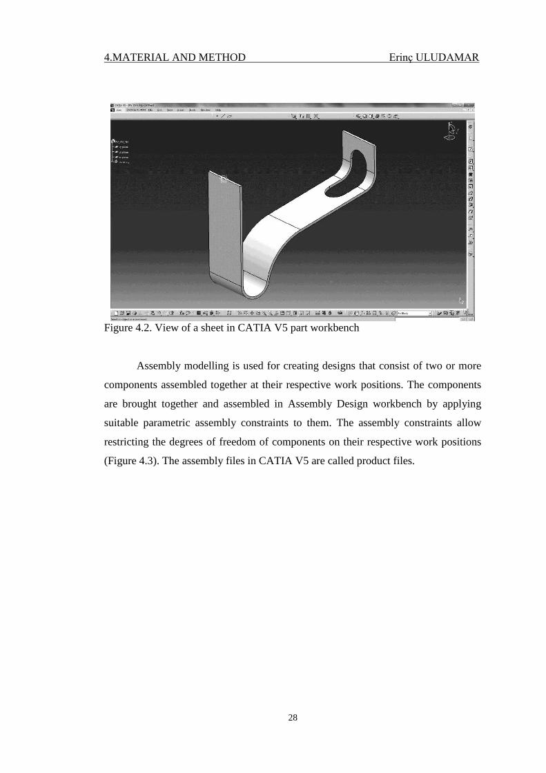
(Figure 4.3). The assembly files in CATIA V5 are called product files.
4.MATERIAL AND METHOD Erinç ULUDAMAR
29
Figure 4.3. View of a subassembly in CATIA V5 assembly workbench
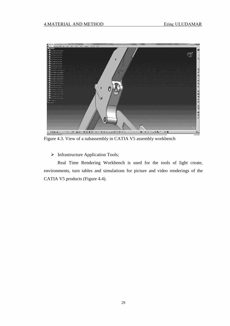
Infrastructure Application Tools;
Real Time Rendering Workbench is used for the tools of light create,
environments, turn tables and simulations for picture and video renderings of the
CATIA V5 products (Figure 4.4).
4.MATERIAL AND METHOD Erinç ULUDAMAR
30
Figure 4.4. Rendered view of the sidelifter in CATIA V5
Digital Mock-up Application Tools;
DMU Kinematics Workbench is provided the tools to help the user apply and
extract kinematics information about a design. As shown in Figure 4.5, part
intersections into assembly detected with the aid of this workbench.
4.MATERIAL AND METHOD Erinç ULUDAMAR
31
Figure 4.5. Clash detection by using DMU kinematics in CATIA V5
Solidworks software program was used for the developments of the
mechanism with RAYVAG Railcar Industry and Trade S.A. Technical drawings of
sidelifter mechanism were prepared with the aid of this program. Parts were prepared
as sheet metal at Solidworks. By using bench, parts have been seen as fold and
unfold through design steps. General view of solid modal and draft of a sheet in
SolidWorks can be seen in Figure 4.6 and Figure 4.7 respectively.
Figure 4.6. General view of solid modal in SolidWorks
4.MATERIAL AND METHOD Erinç ULUDAMAR
32
Figure 4.7. Technical drawing of a sheet in SolidWorks
General view of solid model in CATIA V5 can be seen in Figure 4.8.
Figure 4.8. General view of solid model in CATIA V5
4.MATERIAL AND METHOD Erinç ULUDAMAR
33
4.2. Finite Element Analyses
FEA software typically uses a CAD representation of the physical model. In
this thesis, In order to calculate operation stresses on the prototype 2 different types
of loading operation have been analysed by following the chart in Figure 4.9.
Analyses are carried out in Çukurova University Automotive Engineering
Laboratories with the aid of workstation, which has 2 processors (24 cores) and 32
GB RAM. Although, in practical world, heaviest container has 30.400 kg weight, in
this study, 40.000 kg weight is applied at analyses for unexpected service conditions,
which are;
Distribution of 40 tonnes load on the chassis (to symbolize when the
container is settle on the chassis after loading operation)
40 Tonnes loading from the hooks (to symbolize when the container is
loading and unloading)
The following assumptions have been done in analyses;
It is assumed that the material behaviour is linear elastic and strains are small.
Therefore, linear elastic analysis will be carried out.
Pins and links are assumed rigid.
The loads are applied statically.
It is also assumed that material properties of the structure are homogenous
and not changed after heat treatment (welding operation).
4.MATERIAL AND METHOD Erinç ULUDAMAR
34
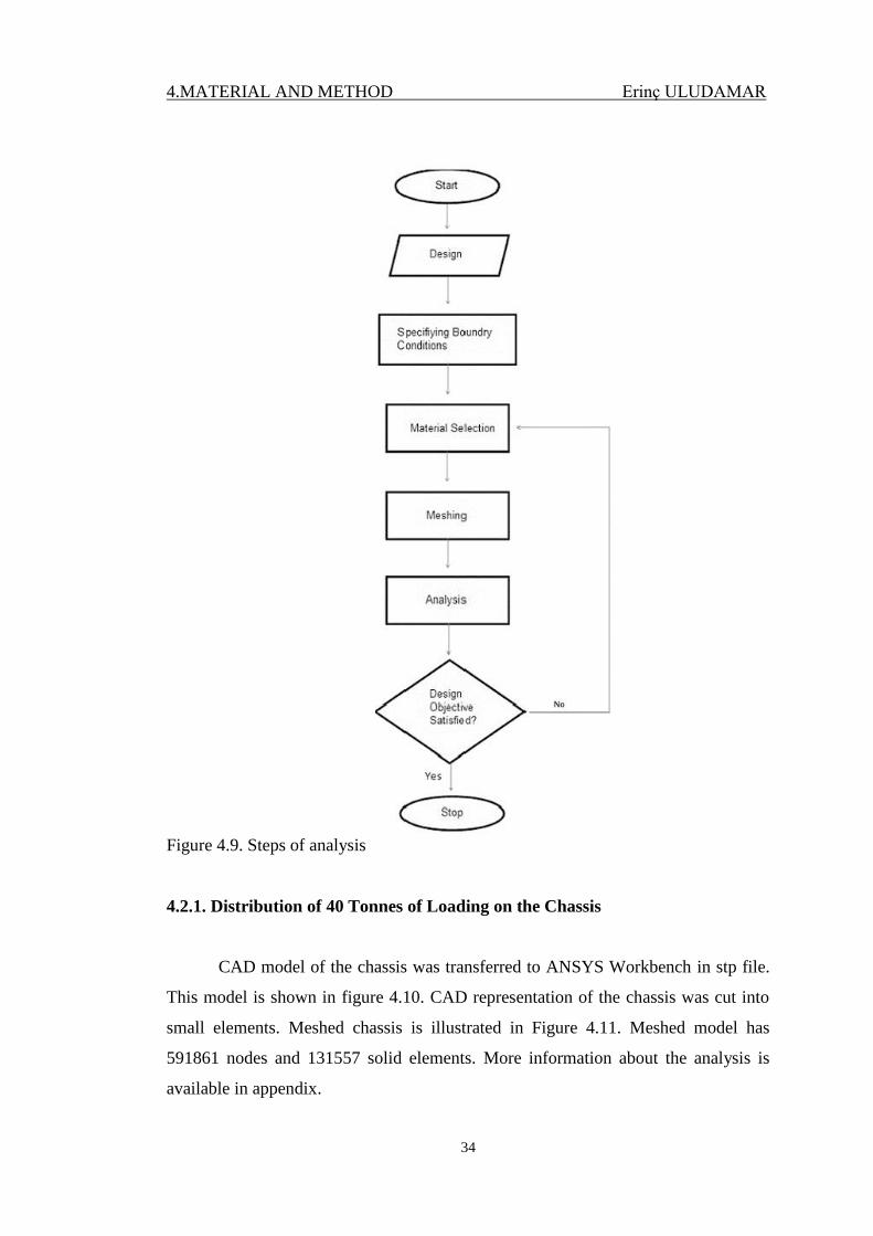
Figure 4.9. Steps of analysis
4.2.1. Distribution of 40 Tonnes of Loading on the Chassis
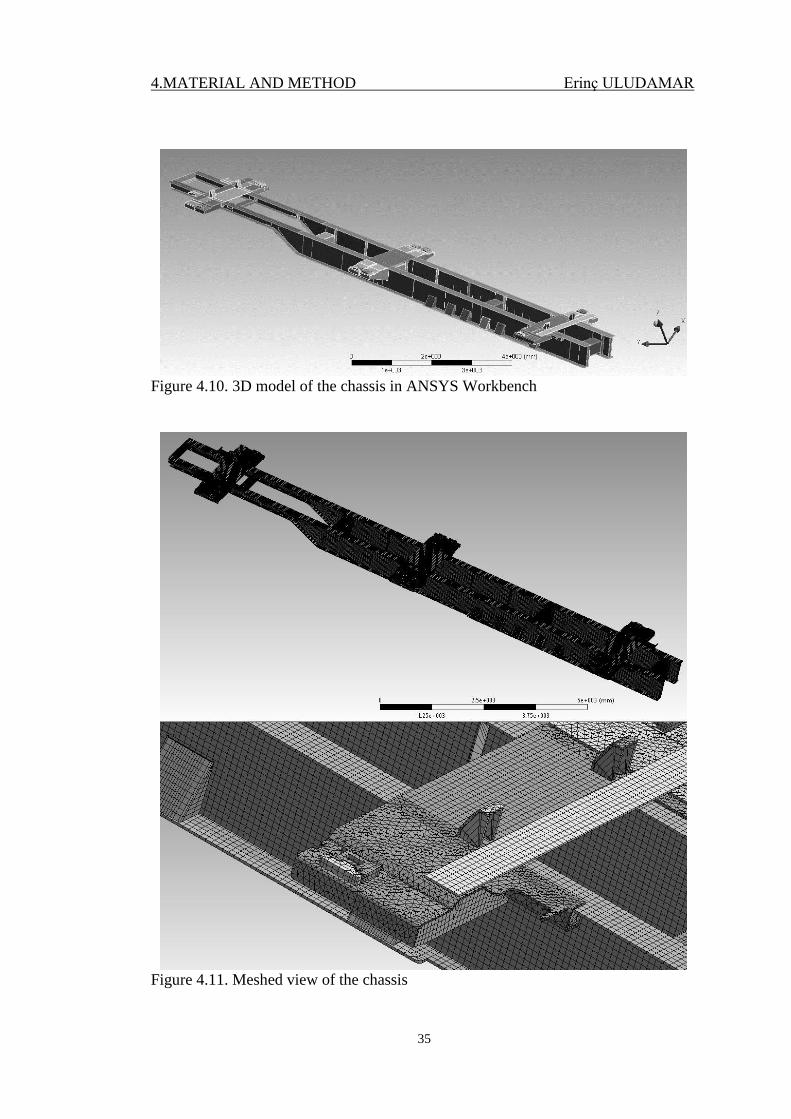
CAD model of the chassis was transferred to ANSYS Workbench in stp file.
This model is shown in figure 4.10. CAD representation of the chassis was cut into
small elements. Meshed chassis is illustrated in Figure 4.11. Meshed model has
591861 nodes and 131557 solid elements. More information about the analysis is
available in appendix.
4.MATERIAL AND METHOD Erinç ULUDAMAR
35
Figure 4.10. 3D model of the chassis in ANSYS Workbench
Figure 4.11. Meshed view of the chassis
4.MATERIAL AND METHOD Erinç ULUDAMAR
36
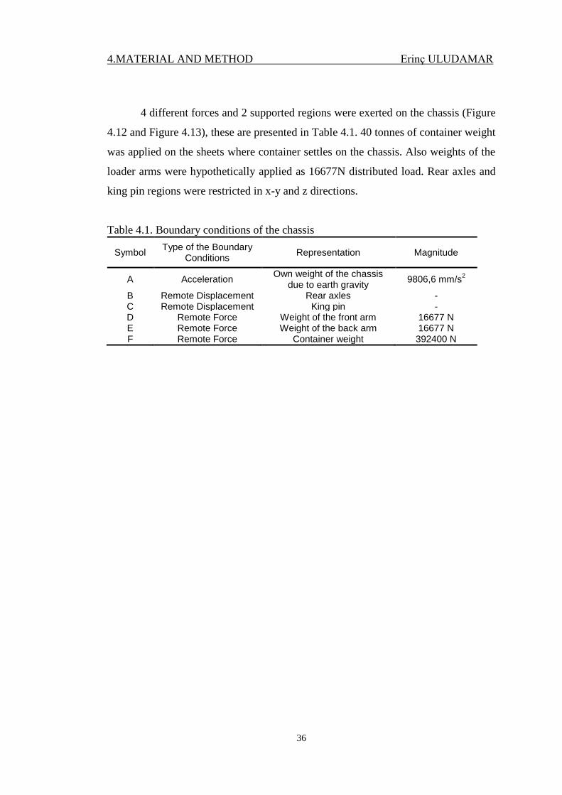
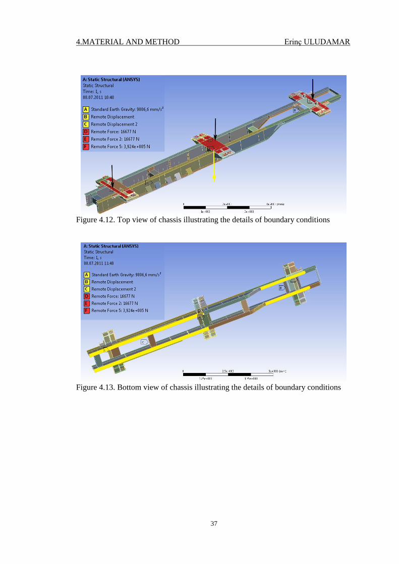
4 different forces and 2 supported regions were exerted on the chassis (Figure
4.12 and Figure 4.13), these are presented in Table 4.1. 40 tonnes of container weight
was applied on the sheets where container settles on the chassis. Also weights of the
loader arms were hypothetically applied as 16677N distributed load. Rear axles and
king pin regions were restricted in x-y and z directions.
Table 4.1. Boundary conditions of the chassis
Symbol Type of the Boundary
Conditions Representation Magnitude
A Acceleration Own weight of the chassis
due to earth gravity 9806,6 mm/s
2
B Remote Displacement Rear axles - C Remote Displacement King pin - D Remote Force Weight of the front arm 16677 N E Remote Force Weight of the back arm 16677 N F Remote Force Container weight 392400 N
4.MATERIAL AND METHOD Erinç ULUDAMAR
37
Figure 4.12. Top view of chassis illustrating the details of boundary conditions
Figure 4.13. Bottom view of chassis illustrating the details of boundary conditions
4.MATERIAL AND METHOD Erinç ULUDAMAR
38
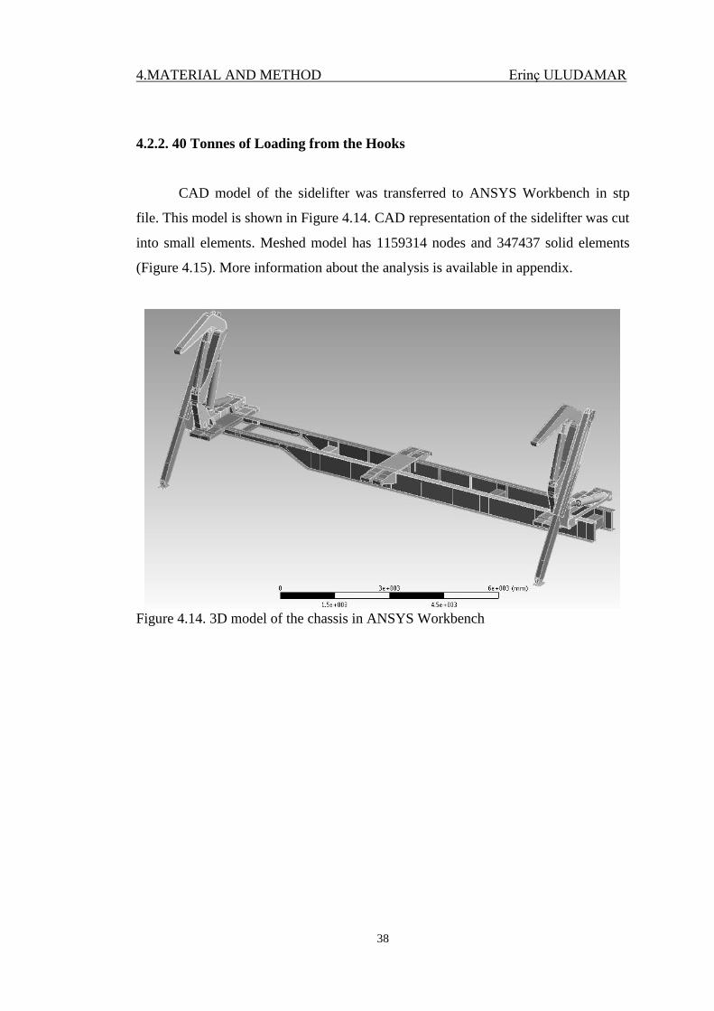
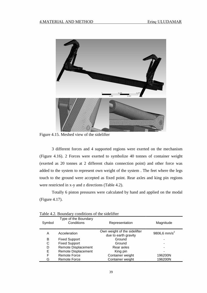
4.2.2. 40 Tonnes of Loading from the Hooks
CAD model of the sidelifter was transferred to ANSYS Workbench in stp
file. This model is shown in Figure 4.14. CAD representation of the sidelifter was cut
into small elements. Meshed model has 1159314 nodes and 347437 solid elements
(Figure 4.15). More information about the analysis is available in appendix.
Figure 4.14. 3D model of the chassis in ANSYS Workbench
4.MATERIAL AND METHOD Erinç ULUDAMAR
39
Figure 4.15. Meshed view of the sidelifter
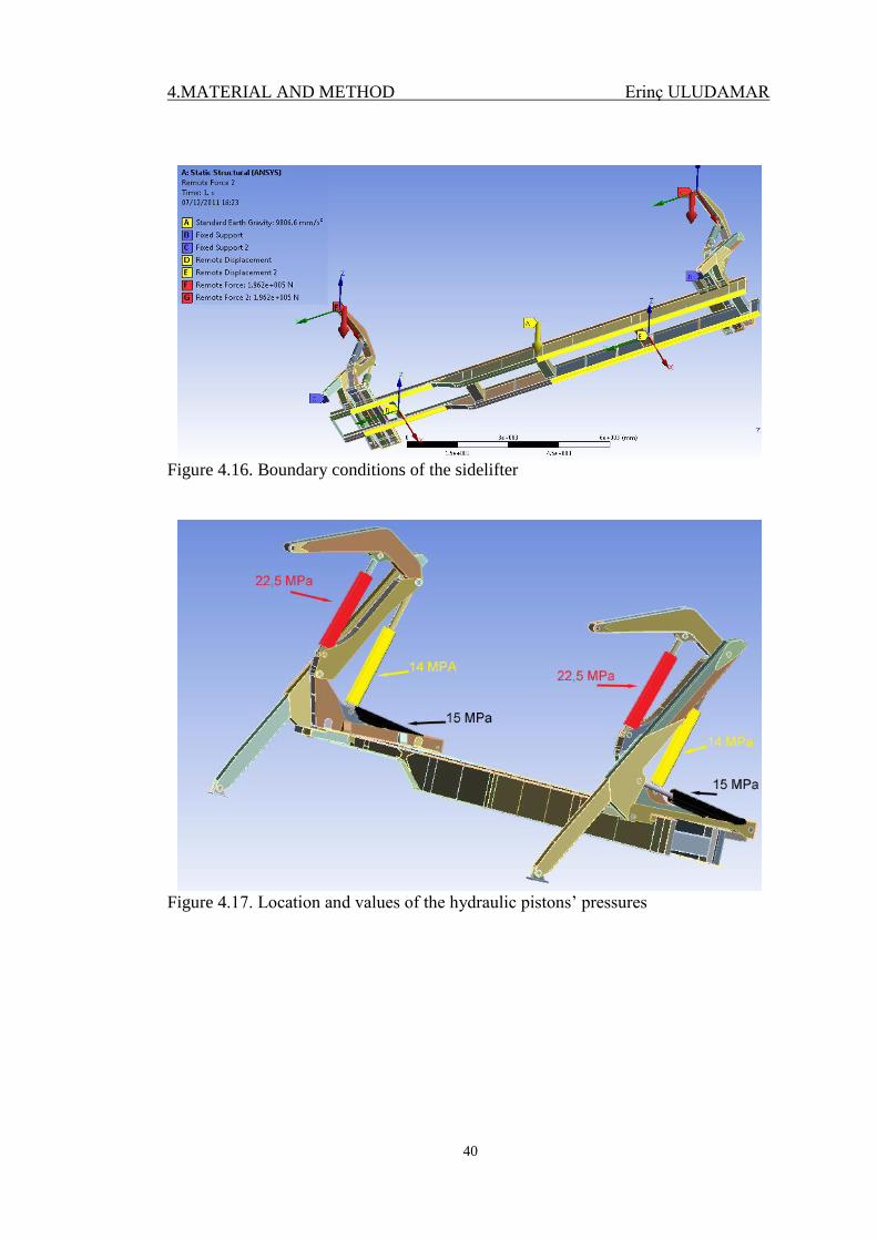
3 different forces and 4 supported regions were exerted on the mechanism
(Figure 4.16). 2 Forces were exerted to symbolize 40 tonnes of container weight
(exerted as 20 tonnes at 2 different chain connection point) and other force was
added to the system to represent own weight of the system . The feet where the legs
touch to the ground were accepted as fixed point. Rear axles and king pin regions
were restricted in x-y and z directions (Table 4.2).
Totally 6 piston pressures were calculated by hand and applied on the modal
(Figure 4.17).
Table 4.2. Boundary conditions of the sidelifter
Symbol Type of the Boundary
Conditions
Representation Magnitude
A Acceleration Own weight of the sidelifter
due to earth gravity 9806,6 mm/s
2
B Fixed Support Ground - C Fixed Support Ground - D Remote Displacement Rear axles - E Remote Displacement King pin - F Remote Force Container weight 196200N G Remote Force Container weight 196200N
4.MATERIAL AND METHOD Erinç ULUDAMAR
40
Figure 4.16. Boundary conditions of the sidelifter
Figure 4.17. Location and values of the hydraulic pistons’ pressures
4.MATERIAL AND METHOD Erinç ULUDAMAR
41
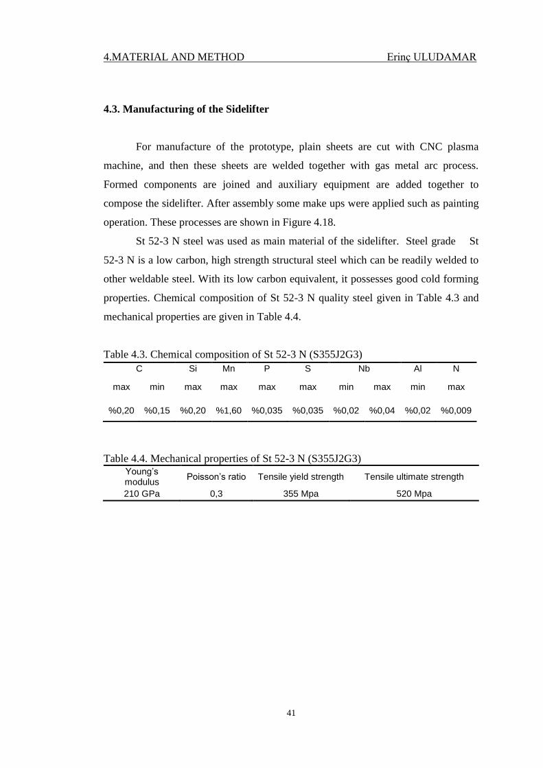
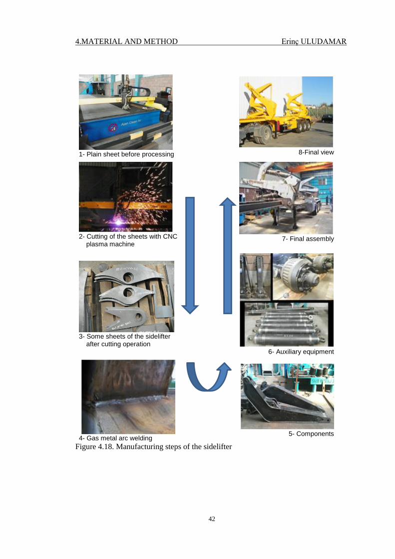
4.3. Manufacturing of the Sidelifter
For manufacture of the prototype, plain sheets are cut with CNC plasma
machine, and then these sheets are welded together with gas metal arc process.
Formed components are joined and auxiliary equipment are added together to
compose the sidelifter. After assembly some make ups were applied such as painting
operation. These processes are shown in Figure 4.18.
St 52-3 N steel was used as main material of the sidelifter. Steel grade St
52-3 N is a low carbon, high strength structural steel which can be readily welded to
other weldable steel. With its low carbon equivalent, it possesses good cold forming
properties. Chemical composition of St 52-3 N quality steel given in Table 4.3 and
mechanical properties are given in Table 4.4.
Table 4.3. Chemical composition of St 52-3 N (S355J2G3)
Table 4.4. Mechanical properties of St 52-3 N (S355J2G3)
Young’s modulus
Poisson’s ratio Tensile yield strength Tensile ultimate strength
210 GPa 0,3 355 Mpa 520 Mpa
C Si Mn P S Nb Al N
max min max max max max min max min max
%0,20 %0,15 %0,20 %1,60 %0,035 %0,035 %0,02 %0,04 %0,02 %0,009
4.MATERIAL AND METHOD Erinç ULUDAMAR
42
1- Plain sheet before processing
8-Final view
2- Cutting of the sheets with CNC plasma machine
7- Final assembly
3- Some sheets of the sidelifter after cutting operation
6- Auxiliary equipment
4- Gas metal arc welding
5- Components
Figure 4.18. Manufacturing steps of the sidelifter
4.MATERIAL AND METHOD Erinç ULUDAMAR
43
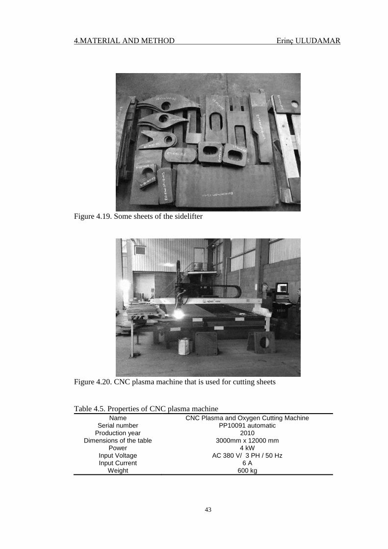
Figure 4.19. Some sheets of the sidelifter
Figure 4.20. CNC plasma machine that is used for cutting sheets
Table 4.5. Properties of CNC plasma machine
Name CNC Plasma and Oxygen Cutting Machine Serial number PP10091 automatic
Production year 2010 Dimensions of the table 3000mm x 12000 mm
Power 4 kW Input Voltage AC 380 V/ 3 PH / 50 Hz Input Current 6 A
Weight 600 kg
4.MATERIAL AND METHOD Erinç ULUDAMAR
44
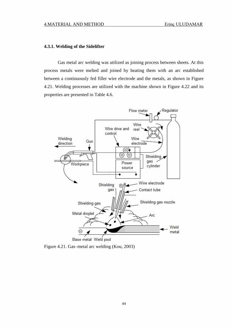
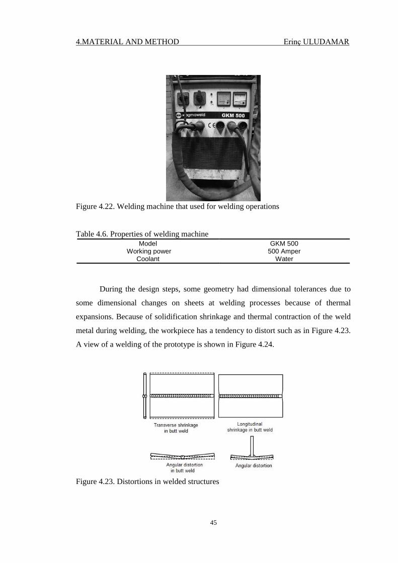
4.3.1. Welding of the Sidelifter
Gas metal arc welding was utilized as joining process between sheets. At this
process metals were melted and joined by heating them with an arc established
between a continuously fed filler wire electrode and the metals, as shown in Figure
4.21. Welding processes are utilized with the machine shown in Figure 4.22 and its
properties are presented in Table 4.6.
Figure 4.21. Gas–metal arc welding (Kou, 2003)
4.MATERIAL AND METHOD Erinç ULUDAMAR
45
Figure 4.22. Welding machine that used for welding operations
Table 4.6. Properties of welding machine
Model GKM 500 Working power 500 Amper
Coolant Water
During the design steps, some geometry had dimensional tolerances due to
some dimensional changes on sheets at welding processes because of thermal
expansions. Because of solidification shrinkage and thermal contraction of the weld
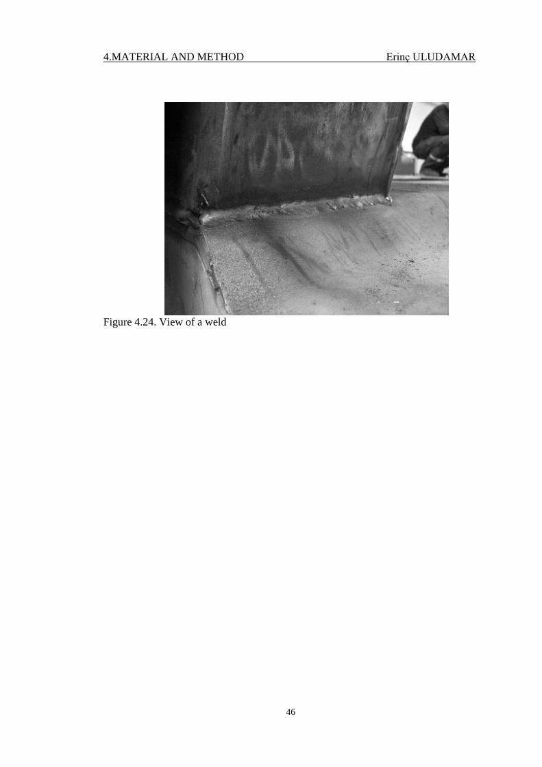
metal during welding, the workpiece has a tendency to distort such as in Figure 4.23.
A view of a welding of the prototype is shown in Figure 4.24.
Figure 4.23. Distortions in welded structures
4.MATERIAL AND METHOD Erinç ULUDAMAR
46
Figure 4.24. View of a weld
4.MATERIAL AND METHOD Erinç ULUDAMAR
47
4.4. Calculations about the Sidelifter
4.4.1. Strength Calculations of the Semi-Trailer’s Chassis
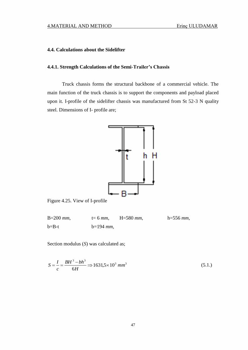
Truck chassis forms the structural backbone of a commercial vehicle. The
main function of the truck chassis is to support the components and payload placed
upon it. I-profile of the sidelifter chassis was manufactured from St 52-3 N quality
steel. Dimensions of I- profile are;
Figure 4.25. View of I-profile
B=200 mm, t= 6 mm, H=580 mm, h=556 mm,
b=B-t b=194 mm,
Section modulus (S) was calculated as;
3333
105,16316
mmH
bhBH
c
IS
(5.1.)
4.MATERIAL AND METHOD Erinç ULUDAMAR
48
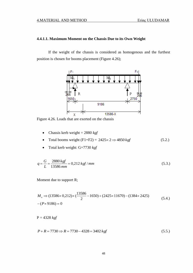
4.4.1.1. Maximum Moment on the Chassis Due to its Own Weight
If the weight of the chassis is considered as homogenous and the furthest
position is chosen for booms placement (Figure 4.26);
Figure 4.26. Loads that are exerted on the chassis
Chassis kerb weight = 2880 kgf
Total booms weight (F1+F2) = kgf 485022425 (5.2.)
Total kerb weight: G=7730 kgf
mmkgfmm
kgf
L
Gq /212,0
13586
2880 (5.3.)
Moment due to support R;
0)9186(
)24251384()116702425()16502
13586()212,013586(
P
Mo (5.4.)
P = 4328 kgf
kgfRRP 3402432877307730 (5.5.)
4.MATERIAL AND METHOD Erinç ULUDAMAR
49
Value and the place of the maximum moment found as;
Maximum moment value is 6825 kgf.m
Maximum moment occurs at x = 10836 mm (on support P)
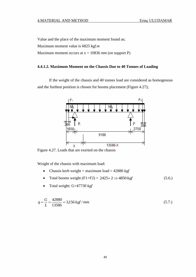
4.4.1.2. Maximum Moment on the Chassis Due to 40 Tonnes of Loading
If the weight of the chassis and 40 tonnes load are considered as homogenous
and the furthest position is chosen for booms placement (Figure 4.27);
Figure 4.27. Loads that are exerted on the chassis
Weight of the chassis with maximum load:
Chassis kerb weight + maximum load = 42880 kgf
Total booms weight (F1+F2) = kgf 485022425 (5.6.)
Total weight: G=47730 kgf
mmkgfL
Gq / 156,3
13586
42880 (5.7.)
4.MATERIAL AND METHOD Erinç ULUDAMAR
50
Moment due to support R;
0)9186(
)24251384()116702425()16502
13586()156,313586(
P
M o (5.8.)
P = 26721 kgf
kgfRkgRP 210092672147730 47730 (5.9.)
Value and the place of the maximum moment;
Maximum moment value is 20696 kgf.m
Maximum moment occurs at x = 5889 m
4.4.1.3. Stress Values and Factor of Safety about the Sidelifter Chassis
2
3
3max1,1
max1 / 183,4mm³ 101631,5
kg.mm 106825mmkgf
W
MG
(5.10.)
2
3
3max1,2
max2 / 69,12mm³ 101631,5
kg.mm 1020696mmkgf
W
MG
(5.11.)
2
max / 69,12 mmkgf
for St 52-3 N material; 22 / 2,36/ 355 mmkgfmmNall (5.12.)
As 22
max / 2,36/ 69,12 mmkgfmmkgf all ; it is safe.
4.MATERIAL AND METHOD Erinç ULUDAMAR
51
4.4.2. Strength Calculations of the Semitrailer’s Axles
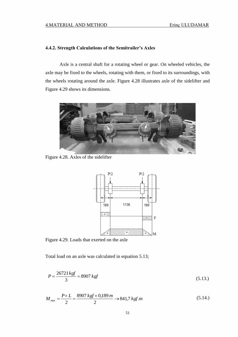
Axle is a central shaft for a rotating wheel or gear. On wheeled vehicles, the
axle may be fixed to the wheels, rotating with them, or fixed to its surroundings, with
the wheels rotating around the axle. Figure 4.28 illustrates axle of the sidelifter and
Figure 4.29 shows its dimensions.
Figure 4.28. Axles of the sidelifter
Figure 4.29. Loads that exerted on the axle
Total load on an axle was calculated in equation 5.13;
(5.13.)
(5.14.)
kgfkgf
P 89073
26721
mkgfmkgfLP
M . 7,8412
189,0 8907
2max
4.MATERIAL AND METHOD Erinç ULUDAMAR
52
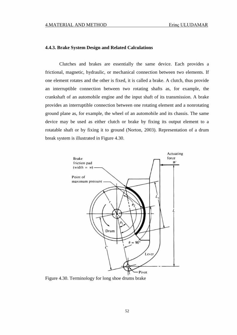
4.4.3. Brake System Design and Related Calculations
Clutches and brakes are essentially the same device. Each provides a
frictional, magnetic, hydraulic, or mechanical connection between two elements. If
one element rotates and the other is fixed, it is called a brake. A clutch, thus provide
an interruptible connection between two rotating shafts as, for example, the
crankshaft of an automobile engine and the input shaft of its transmission. A brake
provides an interruptible connection between one rotating element and a nonrotating
ground plane as, for example, the wheel of an automobile and its chassis. The same
device may be used as either clutch or brake by fixing its output element to a
rotatable shaft or by fixing it to ground (Norton, 2003). Representation of a drum
break system is illustrated in Figure 4.30.
Figure 4.30. Terminology for long shoe drums brake
4.MATERIAL AND METHOD Erinç ULUDAMAR
53
Width = 220 mm,
Radius = 420 mm,
θ1 = 300, θ2 =120
0,
Friction = 0,25,
Maximum Pressure (Assumed) = 1,5 Mpa,
Totally 12 drums on axles
Tire diameter under the load assumed as 0,7 m
)cos(cos 21max
2 pwfrT f (5.15.)
Friction torque on drum: )cos(cos 21max
2 pwfrT f (5.16.)
)120cos30(cos 5,1 22025,0) 420( 002 MPammmmT f (5.17.)
Tf = 14553 Nm
When the vehicle has its gross weight, it should provide at least 4 m/s2
negative
acceleration.
2/ 23,5 477307,0
12 14553sm
M
Fa L
(5.18.)
as 22 /4 / 23,5 smsm , it is safe
4.MATERIAL AND METHOD Erinç ULUDAMAR
54
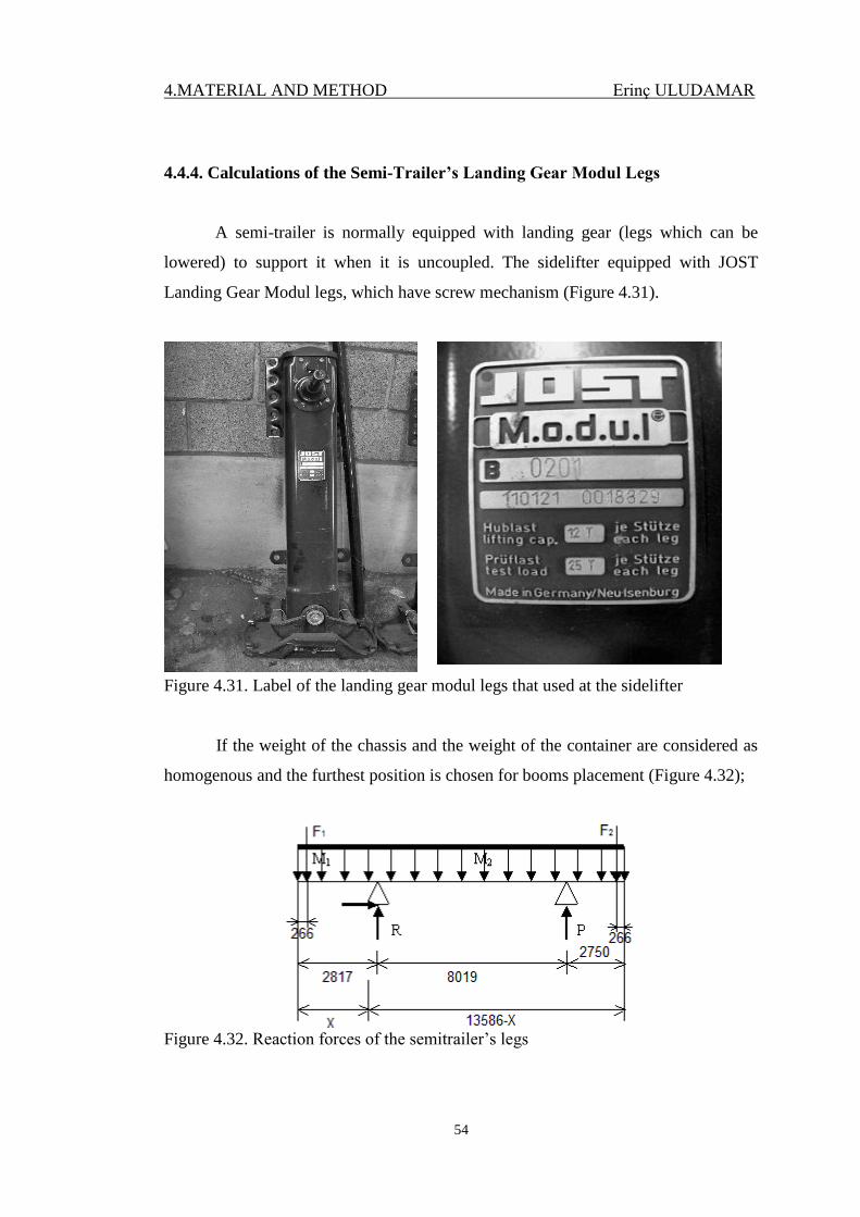
4.4.4. Calculations of the Semi-Trailer’s Landing Gear Modul Legs
A semi-trailer is normally equipped with landing gear (legs which can be
lowered) to support it when it is uncoupled. The sidelifter equipped with JOST
Landing Gear Modul legs, which have screw mechanism (Figure 4.31).
Figure 4.31. Label of the landing gear modul legs that used at the sidelifter
If the weight of the chassis and the weight of the container are considered as
homogenous and the furthest position is chosen for booms placement (Figure 4.32);
Figure 4.32. Reaction forces of the semitrailer’s legs
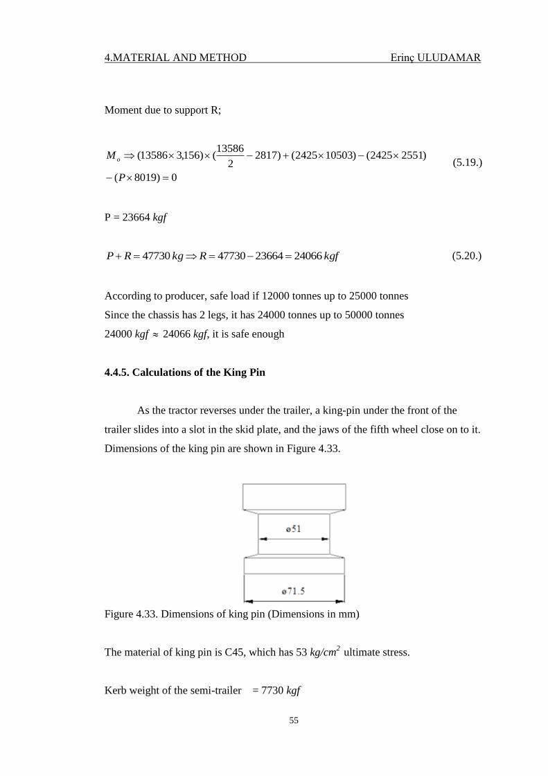
4.MATERIAL AND METHOD Erinç ULUDAMAR
55
Moment due to support R;
0)8019(
)25512425()105032425()28172
13586()156,313586(
P
M o (5.19.)
P = 23664 kgf
kgfRkgRP 240662366447730 47730 (5.20.)
According to producer, safe load if 12000 tonnes up to 25000 tonnes
Since the chassis has 2 legs, it has 24000 tonnes up to 50000 tonnes
24000 kgf 24066 kgf, it is safe enough
4.4.5. Calculations of the King Pin
As the tractor reverses under the trailer, a king-pin under the front of the
trailer slides into a slot in the skid plate, and the jaws of the fifth wheel close on to it.
Dimensions of the king pin are shown in Figure 4.33.
Figure 4.33. Dimensions of king pin (Dimensions in mm)
The material of king pin is C45, which has 53 kg/cm2
ultimate stress.
Kerb weight of the semi-trailer = 7730 kgf
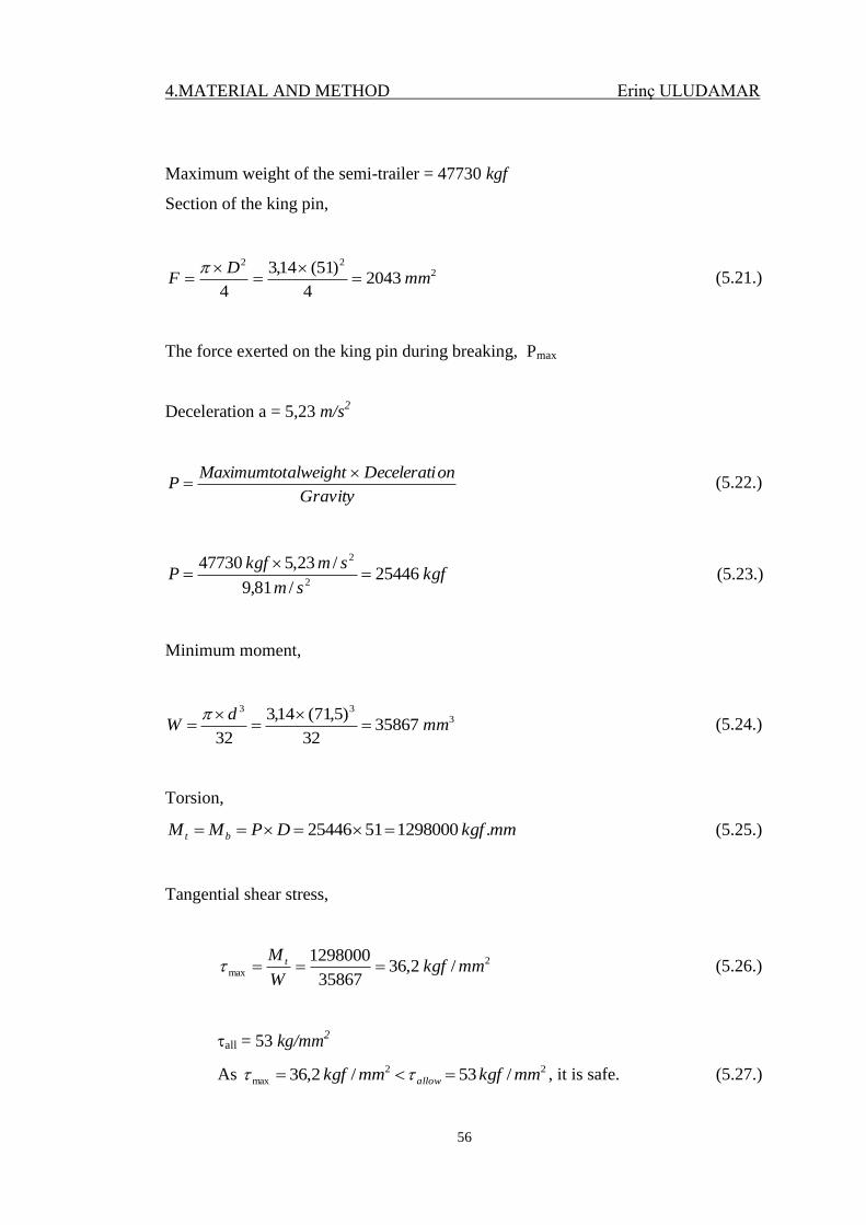
4.MATERIAL AND METHOD Erinç ULUDAMAR
56
Maximum weight of the semi-trailer = 47730 kgf
Section of the king pin,
222
20434
)51(14,3
4mm
DF
(5.21.)
The force exerted on the king pin during breaking, Pmax
Deceleration a = 5,23 m/s2
Gravity
onDeceleratialweightMaximumtotP
(5.22.)
kgfsm
smkgfP 25446
/ 81,9
/ 23,5 477302
2
(5.23.)
Minimum moment,
333
3586732
)5,71(14,3
32mm
dW
(5.24.)
Torsion,
mmkgfDPMM bt . 12980005125446 (5.25.)
Tangential shear stress,
2
max /2,3635867
1298000mmkgf
W
M t (5.26.)
all = 53 kg/mm2
As 22
max / 53 / 2,36 mmkgfmmkgf allow , it is safe. (5.27.)
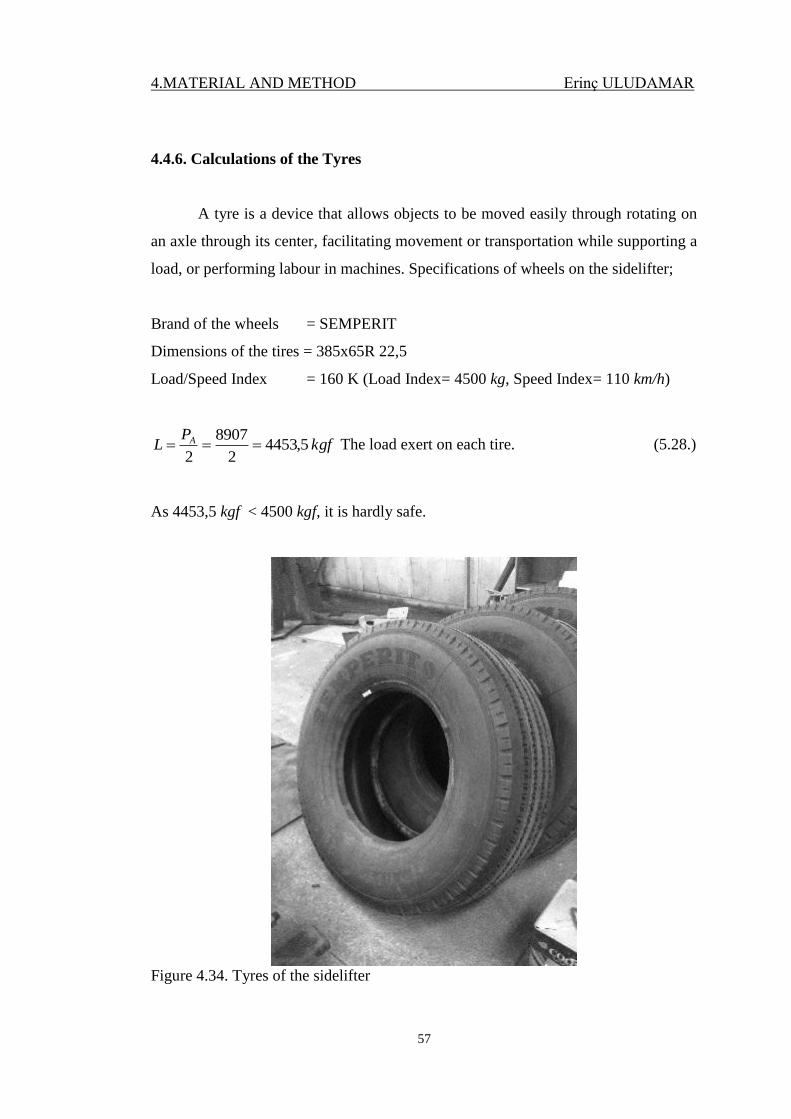
4.MATERIAL AND METHOD Erinç ULUDAMAR
57
4.4.6. Calculations of the Tyres
A tyre is a device that allows objects to be moved easily through rotating on
an axle through its center, facilitating movement or transportation while supporting a
load, or performing labour in machines. Specifications of wheels on the sidelifter;
Brand of the wheels = SEMPERIT
Dimensions of the tires = 385x65R 22,5
Load/Speed Index = 160 K (Load Index= 4500 kg, Speed Index= 110 km/h)
kgfP
L A 5,44532
8907
2 The load exert on each tire. (5.28.)
As 4453,5 kgf < 4500 kgf, it is hardly safe.
Figure 4.34. Tyres of the sidelifter
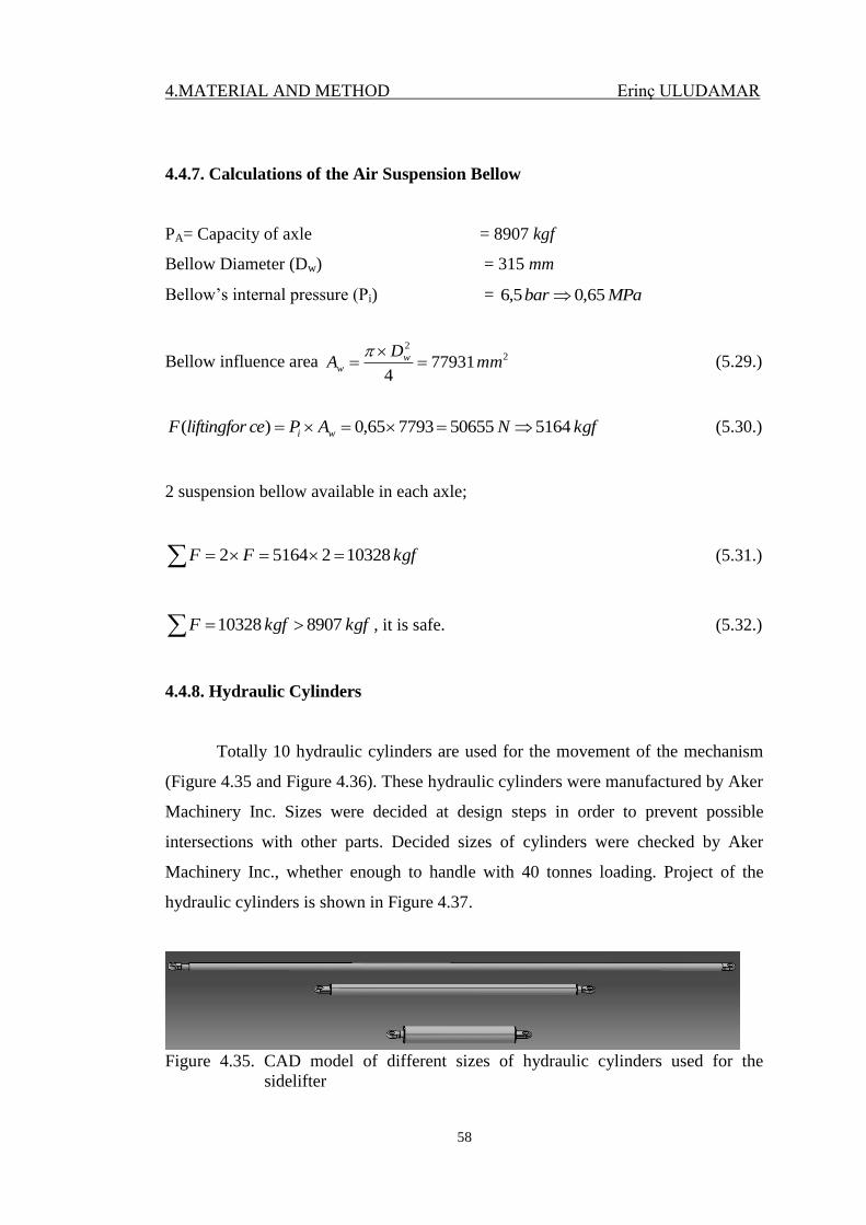
4.MATERIAL AND METHOD Erinç ULUDAMAR
58
4.4.7. Calculations of the Air Suspension Bellow
PA= Capacity of axle = 8907 kgf
Bellow Diameter (Dw) = 315 mm
Bellow’s internal pressure (Pi) = MPabar 65,0 5,6
Bellow influence area 22
779314
mmD
A ww
(5.29.)
kgfNAPceliftingforF wi 5164 50655779365,0)( (5.30.)
2 suspension bellow available in each axle;
kgfFF 10328251642 (5.31.)
kgfkgfF 8907 10328 , it is safe. (5.32.)
4.4.8. Hydraulic Cylinders
Totally 10 hydraulic cylinders are used for the movement of the mechanism
(Figure 4.35 and Figure 4.36). These hydraulic cylinders were manufactured by Aker
Machinery Inc. Sizes were decided at design steps in order to prevent possible
intersections with other parts. Decided sizes of cylinders were checked by Aker
Machinery Inc., whether enough to handle with 40 tonnes loading. Project of the
hydraulic cylinders is shown in Figure 4.37.
Figure 4.35. CAD model of different sizes of hydraulic cylinders used for the
sidelifter
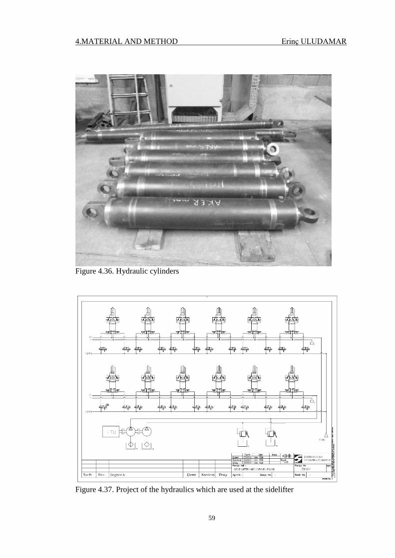
4.MATERIAL AND METHOD Erinç ULUDAMAR
59
Figure 4.36. Hydraulic cylinders
Figure 4.37. Project of the hydraulics which are used at the sidelifter

5. RESULTS AND DISCUSSION Erinç ULUDAMAR
60
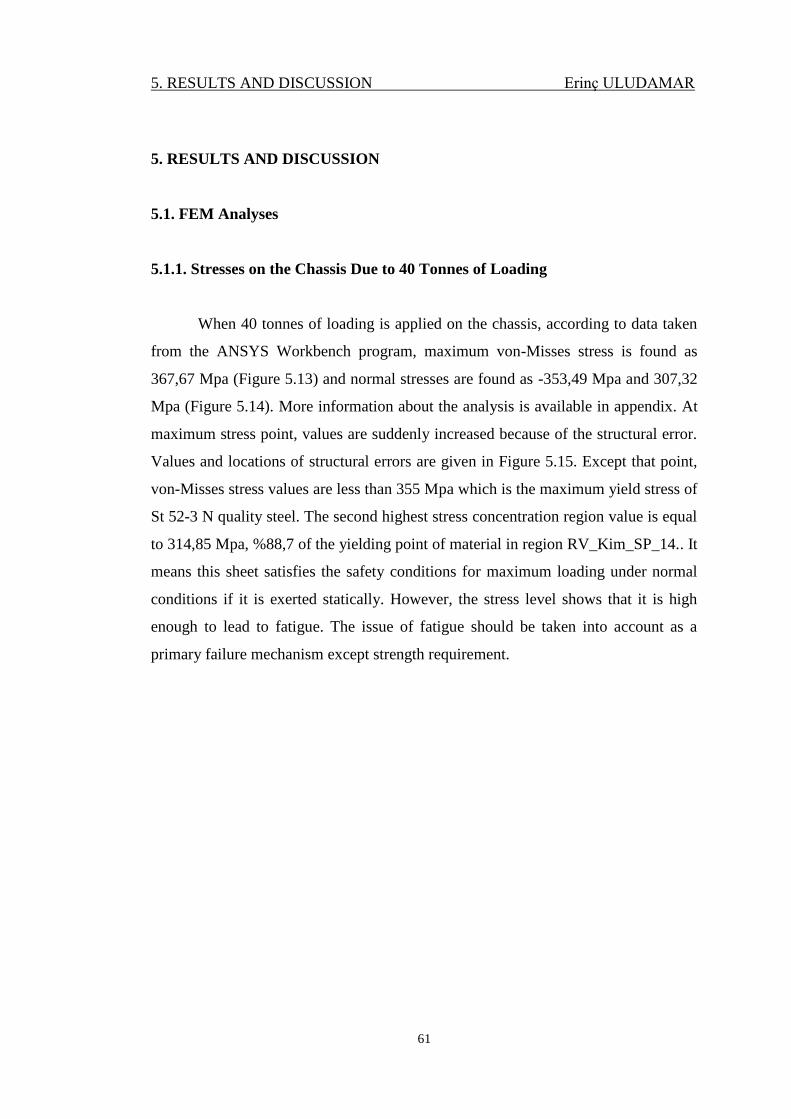
5. RESULTS AND DISCUSSION Erinç ULUDAMAR
61
5. RESULTS AND DISCUSSION
5.1. FEM Analyses
5.1.1. Stresses on the Chassis Due to 40 Tonnes of Loading
When 40 tonnes of loading is applied on the chassis, according to data taken
from the ANSYS Workbench program, maximum von-Misses stress is found as
367,67 Mpa (Figure 5.13) and normal stresses are found as -353,49 Mpa and 307,32
Mpa (Figure 5.14). More information about the analysis is available in appendix. At
maximum stress point, values are suddenly increased because of the structural error.
Values and locations of structural errors are given in Figure 5.15. Except that point,
von-Misses stress values are less than 355 Mpa which is the maximum yield stress of
St 52-3 N quality steel. The second highest stress concentration region value is equal
to 314,85 Mpa, %88,7 of the yielding point of material in region RV_Kim_SP_14.. It
means this sheet satisfies the safety conditions for maximum loading under normal
conditions if it is exerted statically. However, the stress level shows that it is high
enough to lead to fatigue. The issue of fatigue should be taken into account as a
primary failure mechanism except strength requirement.
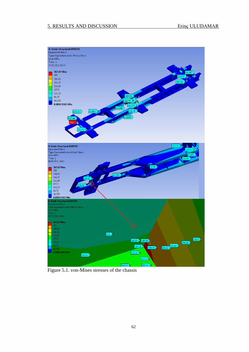
5. RESULTS AND DISCUSSION Erinç ULUDAMAR
62
Figure 5.1. von-Mises stresses of the chassis
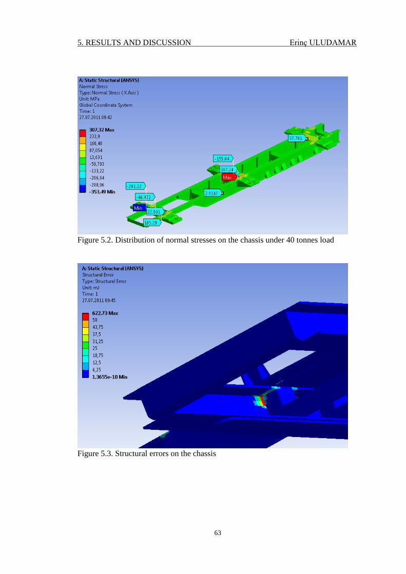
5. RESULTS AND DISCUSSION Erinç ULUDAMAR
63
Figure 5.2. Distribution of normal stresses on the chassis under 40 tonnes load
Figure 5.3. Structural errors on the chassis
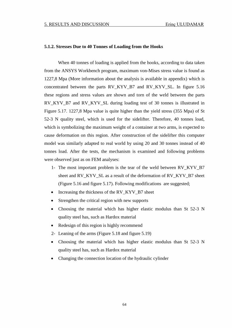
5. RESULTS AND DISCUSSION Erinç ULUDAMAR
64
5.1.2. Stresses Due to 40 Tonnes of Loading from the Hooks
When 40 tonnes of loading is applied from the hooks, according to data taken
from the ANSYS Workbench program, maximum von-Mises stress value is found as
1227,8 Mpa (More information about the analysis is available in appendix) which is
concentrated between the parts RV_KYV_B7 and RV_KYV_SL. In figure 5.16
these regions and stress values are shown and torn of the weld between the parts
RV_KYV_B7 and RV_KYV_SL during loading test of 30 tonnes is illustrated in
Figure 5.17. 1227,8 Mpa value is quite higher than the yield stress (355 Mpa) of St
52-3 N quality steel, which is used for the sidelifter. Therefore, 40 tonnes load,
which is symbolizing the maximum weight of a container at two arms, is expected to
cause deformation on this region. After construction of the sidelifter this computer
model was similarly adapted to real world by using 20 and 30 tonnes instead of 40
tonnes load. After the tests, the mechanism is examined and following problems
were observed just as on FEM analyses:
1- The most important problem is the tear of the weld between RV_KYV_B7
sheet and RV_KYV_SL as a result of the deformation of RV_KYV_B7 sheet
(Figure 5.16 and figure 5.17). Following modifications are suggested;
Increasing the thickness of the RV_KYV_B7 sheet
Strengthen the critical region with new supports
Choosing the material which has higher elastic modulus than St 52-3 N
quality steel has, such as Hardox material
Redesign of this region is highly recommend
2- Leaning of the arms (Figure 5.18 and figure 5.19)
Choosing the material which has higher elastic modulus than St 52-3 N
quality steel has, such as Hardox material
Changing the connection location of the hydraulic cylinder
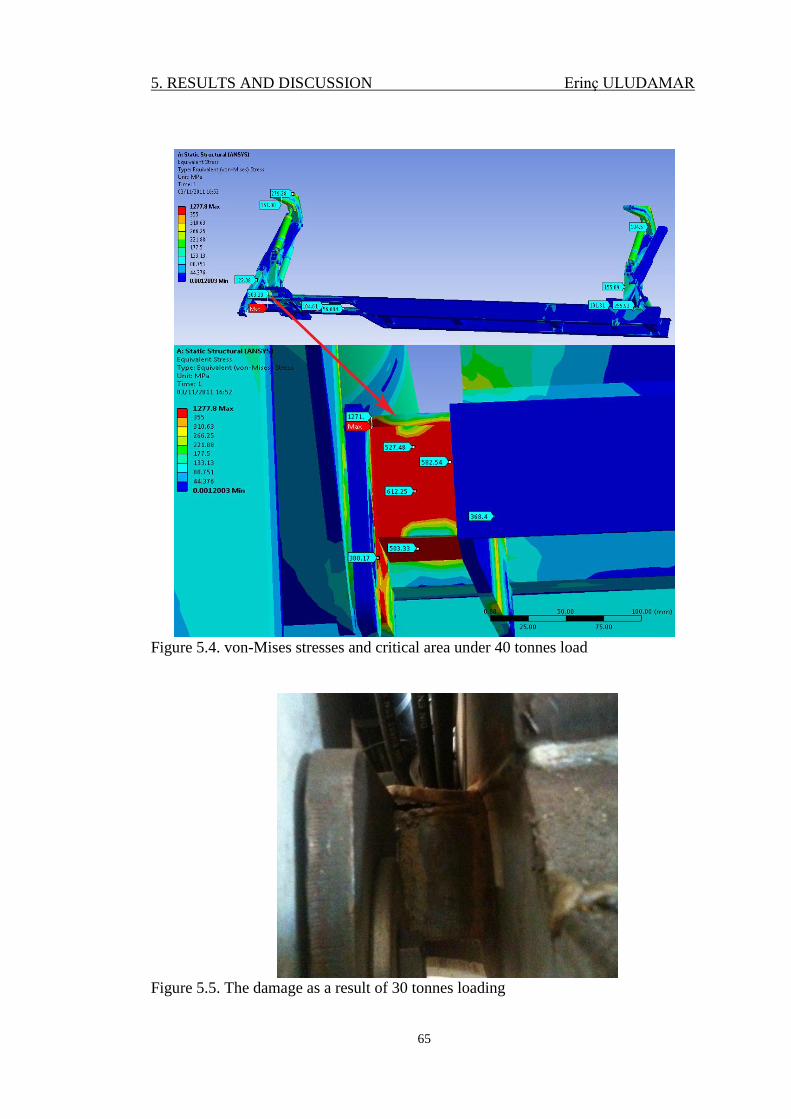
5. RESULTS AND DISCUSSION Erinç ULUDAMAR
65
Figure 5.4. von-Mises stresses and critical area under 40 tonnes load
Figure 5.5. The damage as a result of 30 tonnes loading
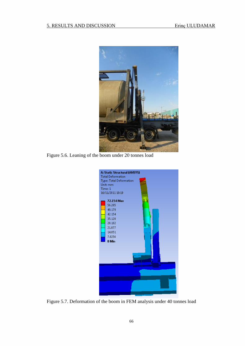
5. RESULTS AND DISCUSSION Erinç ULUDAMAR
66
Figure 5.6. Leaning of the boom under 20 tonnes load
Figure 5.7. Deformation of the boom in FEM analysis under 40 tonnes load
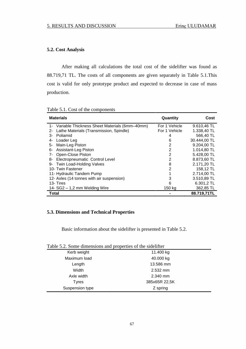
5. RESULTS AND DISCUSSION Erinç ULUDAMAR
67
5.2. Cost Analysis
After making all calculations the total cost of the sidelifter was found as
88.719,71 TL. The costs of all components are given separately in Table 5.1.This
cost is valid for only prototype product and expected to decrease in case of mass
production.
Table 5.1. Cost of the components
Materials Quantity Cost
1- Variable Thickness Sheet Materials (6mm–40mm) For 1 Vehicle 9.610,46 TL 2- Lathe Materials (Transmission, Spindle) For 1 Vehicle 1.338,40 TL 3- Poliamid 4 566,40 TL 4- Loader Leg 6 30.444,00 TL 5- Main-Leg Piston 2 9.204,00 TL 6- Assistant-Leg Piston 2 1.014,80 TL 7- Open-Close Piston 2 5.428,00 TL 8- Electropneumatic Control Level 2 8.873,60 TL 9- Twin Load-Holding Valves 8 2.171,20 TL 10- Twin Fastener 2 158,12 TL 11- Hydraulic Tandem Pump 1 2.714,00 TL 12- Axles (14 tonnes with air suspension) 3 3.510,89 TL 13- Tires 6 6.301,2 TL 14- SG2 – 1,2 mm Welding Wire 150 kg 362,85 TL
Total - 88.719,71TL
5.3. Dimensions and Technical Properties
Basic information about the sidelifter is presented in Table 5.2.
Table 5.2. Some dimensions and properties of the sidelifter
Kerb weight 11.400 kg
Maximum load 40.000 kg
Length 13.586 mm
Width 2.532 mm
Axle width 2.340 mm
Tyres 385x65R 22,5K
Suspension type Z spring
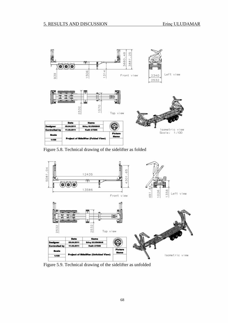
5. RESULTS AND DISCUSSION Erinç ULUDAMAR
68
Figure 5.8. Technical drawing of the sidelifter as folded
Figure 5.9. Technical drawing of the sidelifter as unfolded
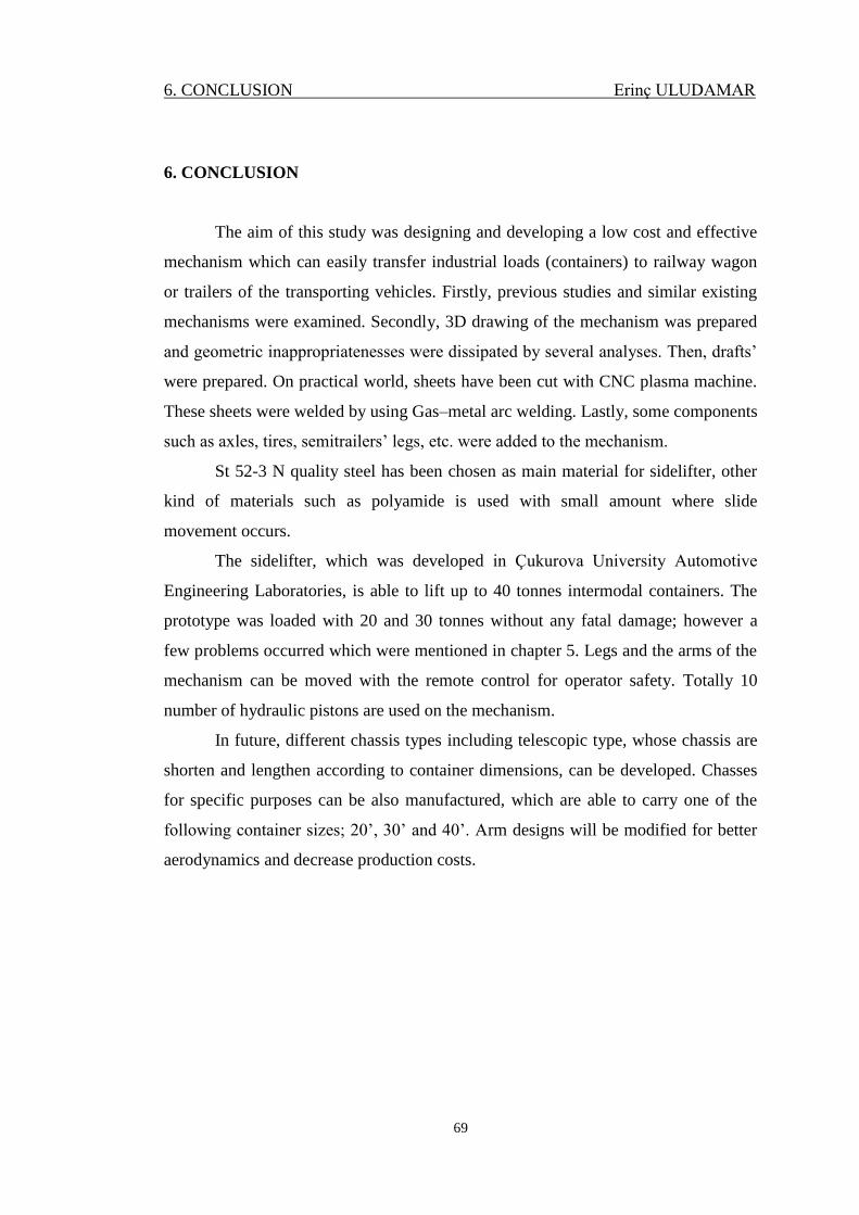
6. CONCLUSION Erinç ULUDAMAR
69
6. CONCLUSION
The aim of this study was designing and developing a low cost and effective
mechanism which can easily transfer industrial loads (containers) to railway wagon
or trailers of the transporting vehicles. Firstly, previous studies and similar existing
mechanisms were examined. Secondly, 3D drawing of the mechanism was prepared
and geometric inappropriatenesses were dissipated by several analyses. Then, drafts’
were prepared. On practical world, sheets have been cut with CNC plasma machine.
These sheets were welded by using Gas–metal arc welding. Lastly, some components
such as axles, tires, semitrailers’ legs, etc. were added to the mechanism.
St 52-3 N quality steel has been chosen as main material for sidelifter, other
kind of materials such as polyamide is used with small amount where slide
movement occurs.
The sidelifter, which was developed in Çukurova University Automotive
Engineering Laboratories, is able to lift up to 40 tonnes intermodal containers. The
prototype was loaded with 20 and 30 tonnes without any fatal damage; however a
few problems occurred which were mentioned in chapter 5. Legs and the arms of the
mechanism can be moved with the remote control for operator safety. Totally 10
number of hydraulic pistons are used on the mechanism.
In future, different chassis types including telescopic type, whose chassis are
shorten and lengthen according to container dimensions, can be developed. Chasses
for specific purposes can be also manufactured, which are able to carry one of the
following container sizes; 20’, 30’ and 40’. Arm designs will be modified for better
aerodynamics and decrease production costs.
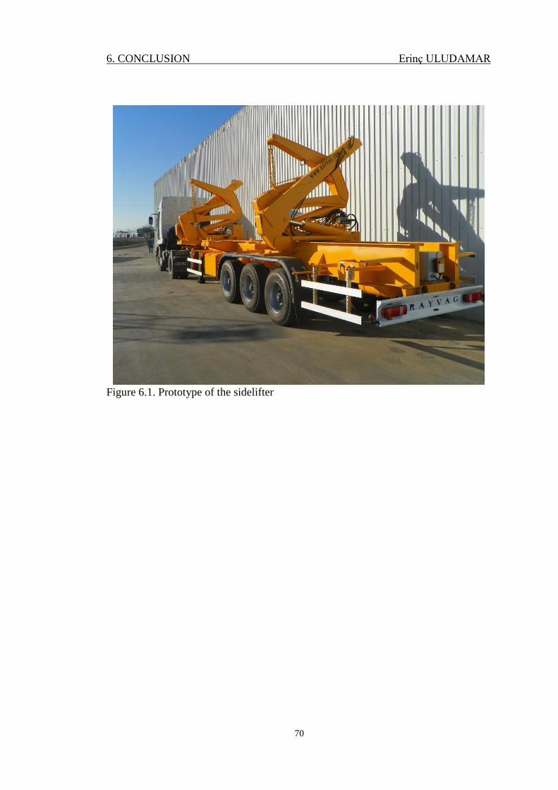
6. CONCLUSION Erinç ULUDAMAR
70
Figure 6.1. Prototype of the sidelifter
71
REFERENCES
ANONYMOUS, 2007. http://www.steelbro.com/net/faqs/ (Access Date: 14 April
2011)
ANONYMOUS, 2011. http://en.wikipedia.org/wiki/Sidelifter (Access date: 16 April
2011)
ANONYMOUS, 2011. http://www.hafen-hamburg.de/en/content/total-port-
container-handling (Access date: 18 April 2011)
ANONYMOUS, 2011a. http://en.wikipedia.org/wiki/CATIA (Access Date: 28 April
2011)
ANONYMOUS, 2011b. http://en.wikipedia.org/wiki/SolidWorks (Access Date: 28
April 2011)
BURDEKIN, M., 2007. Applied metallurgy of steel (B. DAVIDSON and G. W.
OWENS edts). Steel Designers’ Manual, 6th
edition, Blackwell
Publishing, pp. 222-247
CANANN, S. A., LIU, Y. C. and MOBLEY, A. V., 1997. Automatic 3D surface
meshing to address today’s industrial needs. Finite Elements in Analysis
and Design, 25: 185-198.
CORRY, P. and KOZAN, E. 2006. An Assignment Model for Dynamic Load
Planning of intermodal trains. Computers & Operations Research, 33: 1-
17.
FRIES, R., CHOWDHURY, M. and BRUMMOND, J. 2009. Transportation and
Security. Transportation Infrastructure Security Utilizing Intelligent
Transportation Systems, John Wiley & Sons, INC, Hoboken, USA. pp. 4.
GENG, J., YAN, W., XU, W., TAN, K. B. C., HUANG, H. M., LEE, S. Y., XU, H.,
HUANG, L. and CHEN, J., 2008. Finite Element Modelling in Implant
Dentistry (J. GENG, W. YAN and W. XU, edts), Zhejiang University
Press, Hangzhou, pp. 81- 91.
GHIGLIAZZA, R. M., and HOLMES, P., 2002. On the dynamics of cranes, or
spherical pendula with moving supports. International Journal of Non-
Linear Mechanics, 37: 1211-1221.
72
IOANNOU, P. A., 2008. Introduction to Intelligent Freight Transportation (P.
IOANNOU editor). Intelligent Freight Transportation, CRC Press, Boca
Raton, USA, pp. 2 .
KARLINSKI, J., RUSINSKI, E., and SMOLNICKI, T., 2008. Protective Structures
for Construction and Mining Machine Operators. Journal of Automation
in Construction, 17: 232-244.
KIM, K.H., and GÜNTHER, H.O., 2007. Container terminals and terminal
operations (K.H. KIM and H.O. GÜNTHER). Container Terminals and
Cargo Systems: Design, Operations Management, and Logistics Control
Issues, Springer, Berlin, Germany, pp. 3-12.
KOU, S., 2003. Welding Metallurgy, 2nd
edition. USA, 454p.
LIU, G. R. and QUEK, S. S., 2003. Computational Modelling (G. R. LIU and S. S.
QUEK, edts). Finite Element Method: A Practical Course, Butterworth-
Heinemanni, Oxford, UK, pp. 1-11
MIRALBES, R., and CASTEJON, L., 2009. Design and Optimization of Crane Jibs
for Forklift Trucks. Proceedings of the World Congress Analysis, July, 1-
3, London, United Kingdom.
MOAVENI, S., 2008. Three-Dimensional Elements (HORTON M. J. and FISCHER
L. edts). Finite Element Analysis Theory and Application with ANSYS,
3rd edition, Prentice Hall, USA, pp. 687-753.
MOMME, J. and HVOLBY, H. H., 2002. An Outsourcing Framework: Action
Research in the Heavy Industry Sector. European Journal of Purchasing &
Supply Management, 8:185–196.
MOTT, R. L., 2004. Materials in Mechanical Design (S. HELBA edts). Machine
Elements in Mechanical Engineering, 4th edition, Courier Westford Inc.,
Westford, pp. 29-82
MURTY, K. G., LIU, J. and LINN, R., 2005. A decision support system for
operations in a container terminal. Decision Support Systems, 39:209-
332.
73
NISHIMURA, E., IMAI, A., JANSSENS, G.K., and PAPADIMITRIOU, S., 2009.
Container Storage and Transshipment Marine Terminals. Transportation
Research Part E, 45: 771-786.
NORTON, R. L., 2006. Machine Design: an integrated approach, 3rd edition ,
Prentice Hall, USA, pp. 12.
ROKACH, A. J., 1991. Structural Steel Design. McGraw Hill, USA, p. 3.
RUSINSKI, E., CZMOCHOWSKI, J., and MOCZKI, P., 2006. Numerical and
Experimental Analysis of a Mine’s Loader Boom Crack. Journal of
Achievements of Materials and Manufacturing Engineering, 17(2): 273-
276.
SASAKI, T. and KAWASHIMA, K., 2008. Remote control of backhoe at
construction site with a pneumatic robot system. Automation in
Construction, 17: 907-914
SASAKI, T., and KAWASHIMA, K., 2008. Remote control of backhoe at
construction site with a pneumatic robot system. Automation in
Construction, 17: 907-914.
TRAPPEY, C. V., LIN, G.Y.P., TRAPPEY, A.J.C., LIU, C.S. and LEE, W.T., (in
press) Deriving Industrial Logistics Hub Reference Models for
Manufacturing Based Economies. Expert Systems with Applications.
UGURLU, U., 2011. http://www.aktueldeniz.com/article_print.php?article_id=84
(Access Date: 02 May 2011)
VIS, I. F. A. and KOSTER, R., 2003. Transshipment of containers at a container
terminal: An overview. European Journal of Operational Research, 147:1-
16.
WOODBURN, A., ALLEN, J., BROWNE, M., LEONARDI, J., and ESSEN, V. H.,
2010. International Road and Rail Freight Transport: The Impact of
Globalisation on Activity Levels (N. A. BRAATHEN editor).
Globalisation, Transport and the Environment, OECD Publishing. Paris,
France, pp.151.
ZAHAVI, E. and BARLAM, D., 2001. Nonlinear Problems in Machine Design.
CRC Press LLC, USA, pp. 406.

74
75
CURRICULUM VITAE
Erinç ULUDAMAR was born in Adana in 1986. After being graduated
Adana Gündoğdu College, he attended to Mechanical Engineering Department of
Çukurova University. He graduated from Çukurova University as a Mechanical
Engineer in 2009. He started his Master of Science education in Mechanical
Engineering Department of Çukurova University in 2009. He has been working as a
Research Assistant at the Mechanical Engineering Department of Çukurova
University since 2010.

76

77
APPENDIX

78
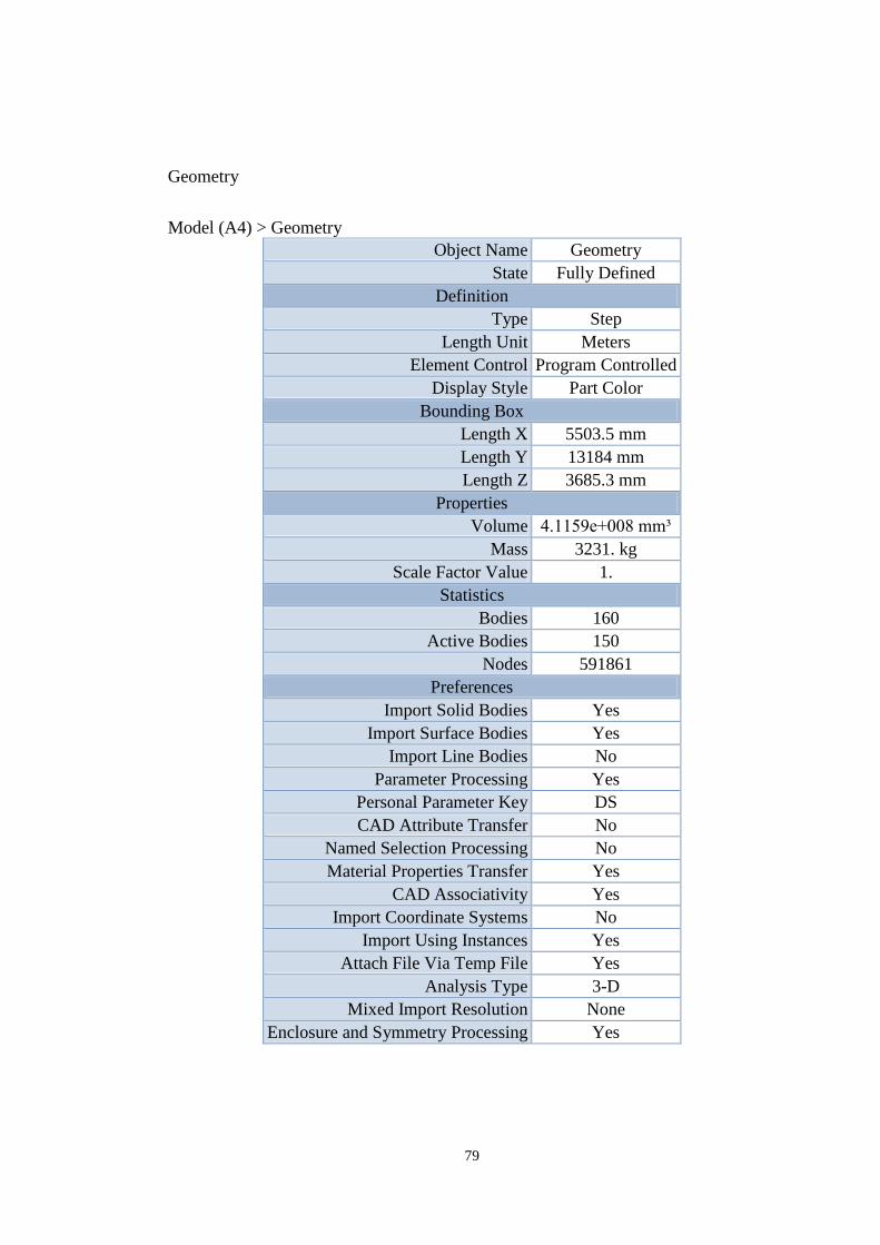
79
Geometry
Model (A4) > Geometry
Object Name Geometry
State Fully Defined
Definition
Type Step
Length Unit Meters
Element Control Program Controlled
Display Style Part Color
Bounding Box
Length X 5503.5 mm
Length Y 13184 mm
Length Z 3685.3 mm
Properties
Volume 4.1159e+008 mm³
Mass 3231. kg
Scale Factor Value 1.
Statistics
Bodies 160
Active Bodies 150
Nodes 591861
Preferences
Import Solid Bodies Yes
Import Surface Bodies Yes
Import Line Bodies No
Parameter Processing Yes
Personal Parameter Key DS
CAD Attribute Transfer No
Named Selection Processing No
Material Properties Transfer Yes
CAD Associativity Yes
Import Coordinate Systems No
Import Using Instances Yes
Attach File Via Temp File Yes
Analysis Type 3-D
Mixed Import Resolution None
Enclosure and Symmetry Processing Yes
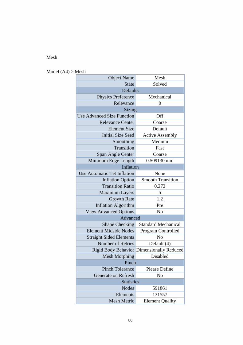
80
Mesh
Model (A4) > Mesh
Object Name Mesh
State Solved
Defaults
Physics Preference Mechanical
Relevance 0
Sizing
Use Advanced Size Function Off
Relevance Center Coarse
Element Size Default
Initial Size Seed Active Assembly
Smoothing Medium
Transition Fast
Span Angle Center Coarse
Minimum Edge Length 0.509130 mm
Inflation
Use Automatic Tet Inflation None
Inflation Option Smooth Transition
Transition Ratio 0.272
Maximum Layers 5
Growth Rate 1.2
Inflation Algorithm Pre
View Advanced Options No
Advanced
Shape Checking Standard Mechanical
Element Midside Nodes Program Controlled
Straight Sided Elements No
Number of Retries Default (4)
Rigid Body Behavior Dimensionally Reduced
Mesh Morphing Disabled
Pinch
Pinch Tolerance Please Define
Generate on Refresh No
Statistics
Nodes 591861
Elements 131557
Mesh Metric Element Quality
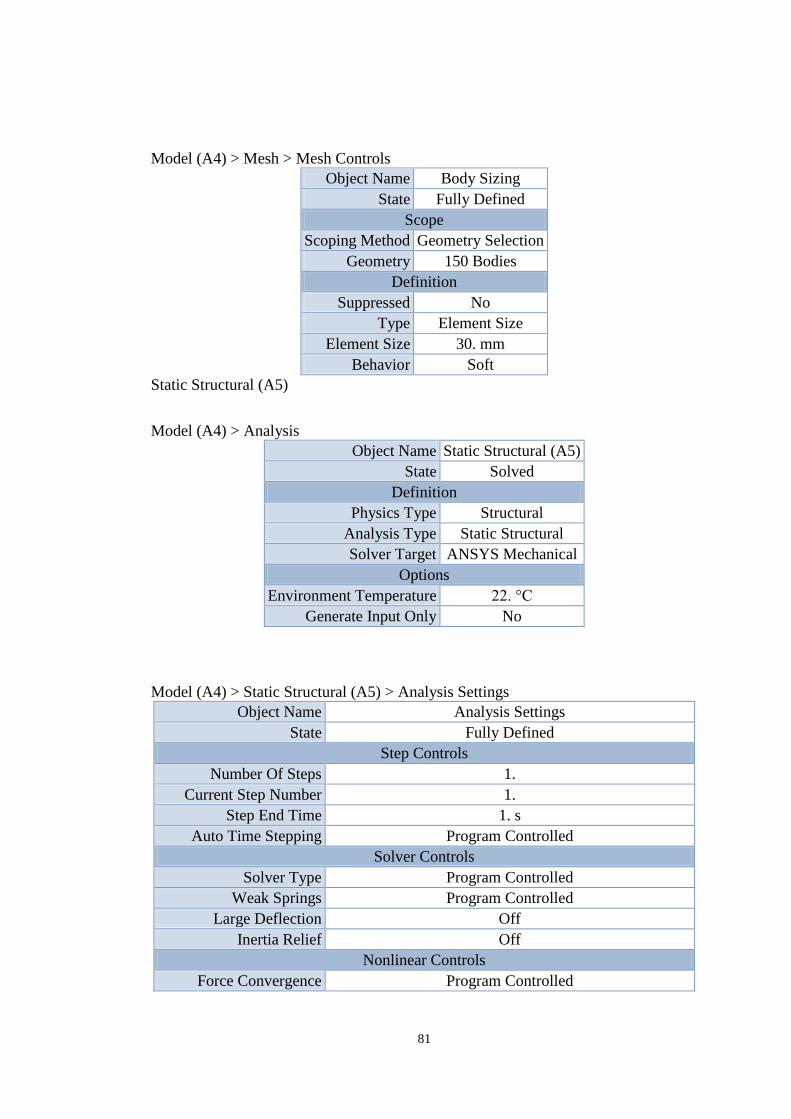
81
Model (A4) > Mesh > Mesh Controls
Object Name Body Sizing
State Fully Defined
Scope
Scoping Method Geometry Selection
Geometry 150 Bodies
Definition
Suppressed No
Type Element Size
Element Size 30. mm
Behavior Soft
Static Structural (A5)
Model (A4) > Analysis
Object Name Static Structural (A5)
State Solved
Definition
Physics Type Structural
Analysis Type Static Structural
Solver Target ANSYS Mechanical
Options
Environment Temperature 22. °C
Generate Input Only No
Model (A4) > Static Structural (A5) > Analysis Settings
Object Name Analysis Settings
State Fully Defined
Step Controls
Number Of Steps 1.
Current Step Number 1.
Step End Time 1. s
Auto Time Stepping Program Controlled
Solver Controls
Solver Type Program Controlled
Weak Springs Program Controlled
Large Deflection Off
Inertia Relief Off
Nonlinear Controls
Force Convergence Program Controlled
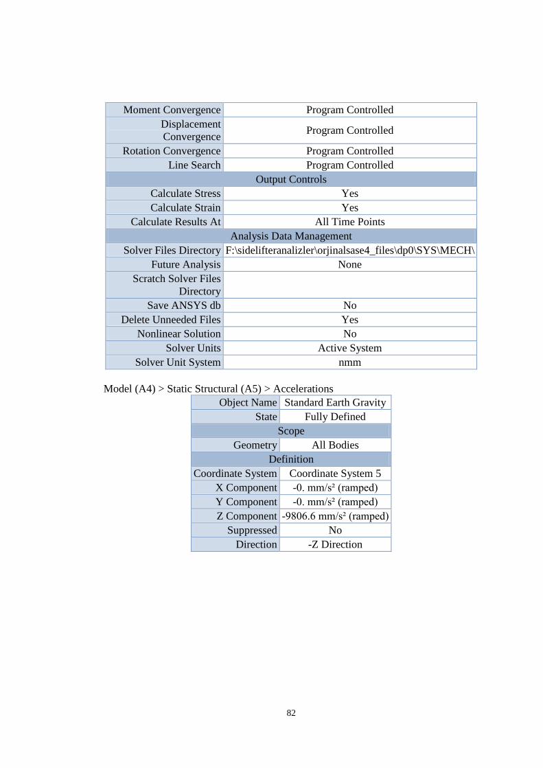
82
Moment Convergence Program Controlled
Displacement
Convergence Program Controlled
Rotation Convergence Program Controlled
Line Search Program Controlled
Output Controls
Calculate Stress Yes
Calculate Strain Yes
Calculate Results At All Time Points
Analysis Data Management
Solver Files Directory F:\sidelifteranalizler\orjinalsase4_files\dp0\SYS\MECH\
Future Analysis None
Scratch Solver Files
Directory
Save ANSYS db No
Delete Unneeded Files Yes
Nonlinear Solution No
Solver Units Active System
Solver Unit System nmm
Model (A4) > Static Structural (A5) > Accelerations
Object Name Standard Earth Gravity
State Fully Defined
Scope
Geometry All Bodies
Definition
Coordinate System Coordinate System 5
X Component -0. mm/s² (ramped)
Y Component -0. mm/s² (ramped)
Z Component -9806.6 mm/s² (ramped)
Suppressed No
Direction -Z Direction
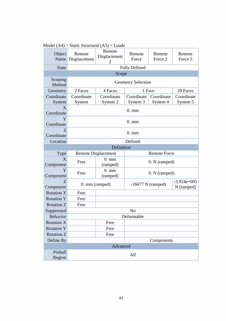
83
Model (A4) > Static Structural (A5) > Loads
Object
Name
Remote
Displacement
Remote
Displacement
2
Remote
Force
Remote
Force 2
Remote
Force 5
State Fully Defined
Scope
Scoping
Method Geometry Selection
Geometry 2 Faces 4 Faces 1 Face 29 Faces
Coordinate
System
Coordinate
System
Coordinate
System 2
Coordinate
System 3
Coordinate
System 4
Coordinate
System 5
X
Coordinate 0. mm
Y
Coordinate 0. mm
Z
Coordinate 0. mm
Location Defined
Definition
Type Remote Displacement Remote Force
X
Component Free
0. mm
(ramped) 0. N (ramped)
Y
Component Free
0. mm
(ramped) 0. N (ramped)
Z
Component 0. mm (ramped) -16677 N (ramped)
-3.924e+005
N (ramped)
Rotation X Free
Rotation Y Free
Rotation Z Free
Suppressed No
Behavior Deformable
Rotation X Free
Rotation Y Free
Rotation Z Free
Define By Components
Advanced
Pinball
Region All
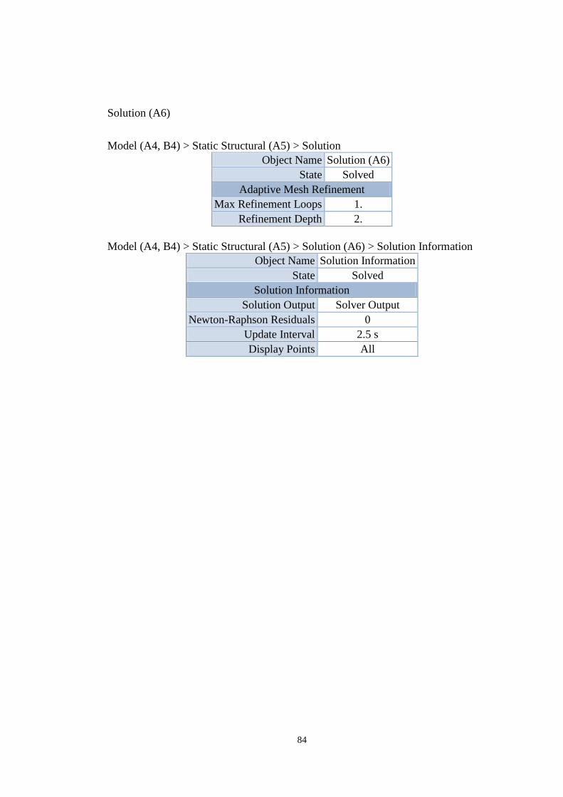
84
Solution (A6)
Model (A4, B4) > Static Structural (A5) > Solution
Object Name Solution (A6)
State Solved
Adaptive Mesh Refinement
Max Refinement Loops 1.
Refinement Depth 2.
Model (A4, B4) > Static Structural (A5) > Solution (A6) > Solution Information
Object Name Solution Information
State Solved
Solution Information
Solution Output Solver Output
Newton-Raphson Residuals 0
Update Interval 2.5 s
Display Points All
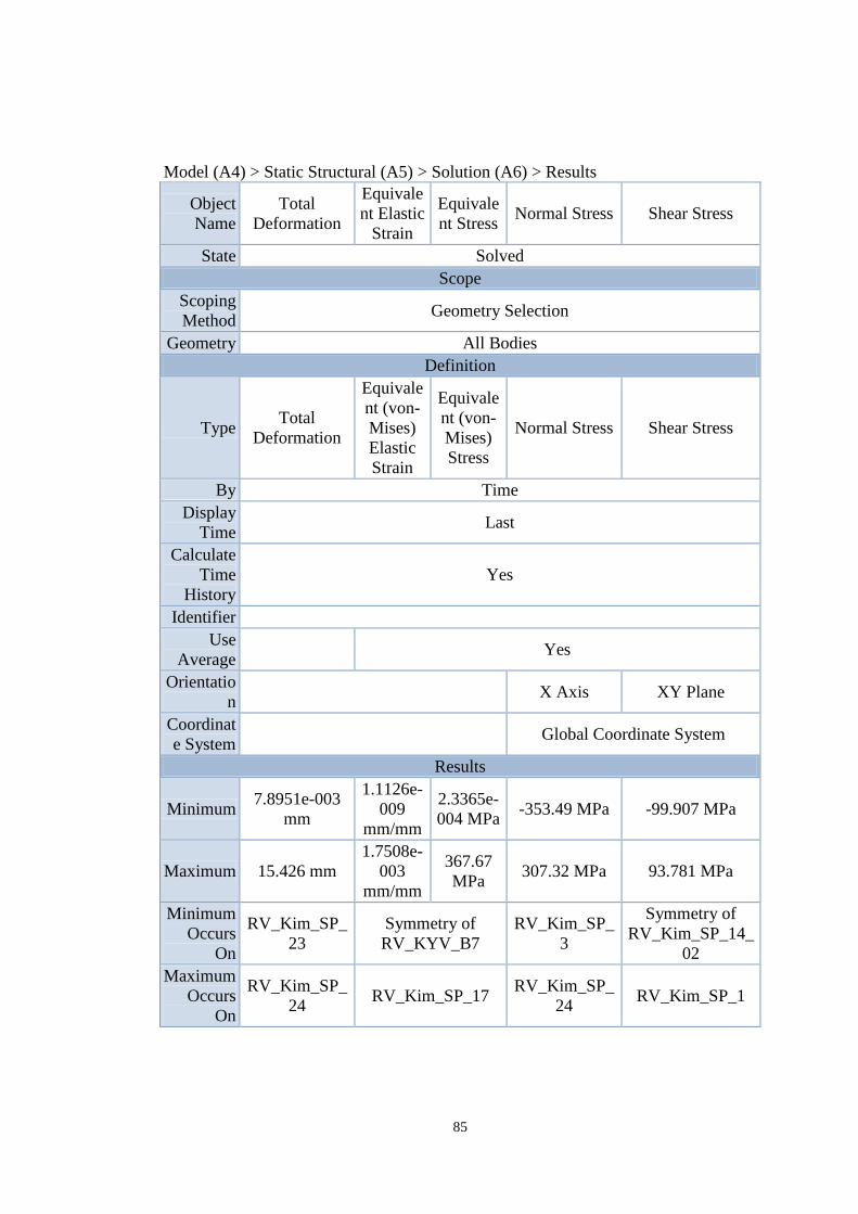
85
Model (A4) > Static Structural (A5) > Solution (A6) > Results
Object
Name
Total
Deformation
Equivale
nt Elastic
Strain
Equivale
nt Stress Normal Stress Shear Stress
State Solved
Scope
Scoping
Method Geometry Selection
Geometry All Bodies
Definition
Type Total
Deformation
Equivale
nt (von-
Mises)
Elastic
Strain
Equivale
nt (von-
Mises)
Stress
Normal Stress Shear Stress
By Time
Display
Time Last
Calculate
Time
History
Yes
Identifier
Use
Average Yes
Orientatio
n X Axis XY Plane
Coordinat
e System Global Coordinate System
Results
Minimum 7.8951e-003
mm
1.1126e-
009
mm/mm
2.3365e-
004 MPa -353.49 MPa -99.907 MPa
Maximum 15.426 mm
1.7508e-
003
mm/mm
367.67
MPa 307.32 MPa 93.781 MPa
Minimum
Occurs
On
RV_Kim_SP_
23
Symmetry of
RV_KYV_B7
RV_Kim_SP_
3
Symmetry of
RV_Kim_SP_14_
02
Maximum
Occurs
On
RV_Kim_SP_
24 RV_Kim_SP_17
RV_Kim_SP_
24 RV_Kim_SP_1
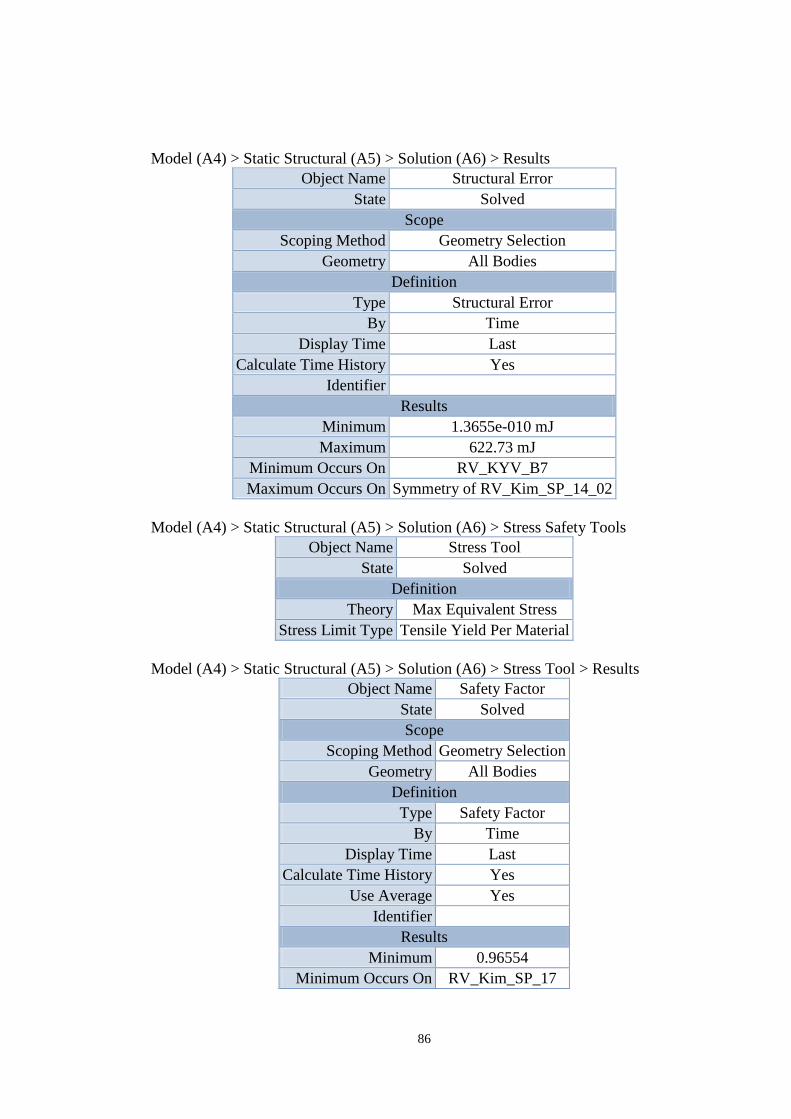
86
Model (A4) > Static Structural (A5) > Solution (A6) > Results
Object Name Structural Error
State Solved
Scope
Scoping Method Geometry Selection
Geometry All Bodies
Definition
Type Structural Error
By Time
Display Time Last
Calculate Time History Yes
Identifier
Results
Minimum 1.3655e-010 mJ
Maximum 622.73 mJ
Minimum Occurs On RV_KYV_B7
Maximum Occurs On Symmetry of RV_Kim_SP_14_02
Model (A4) > Static Structural (A5) > Solution (A6) > Stress Safety Tools
Object Name Stress Tool
State Solved
Definition
Theory Max Equivalent Stress
Stress Limit Type Tensile Yield Per Material
Model (A4) > Static Structural (A5) > Solution (A6) > Stress Tool > Results
Object Name Safety Factor
State Solved
Scope
Scoping Method Geometry Selection
Geometry All Bodies
Definition
Type Safety Factor
By Time
Display Time Last
Calculate Time History Yes
Use Average Yes
Identifier
Results
Minimum 0.96554
Minimum Occurs On RV_Kim_SP_17
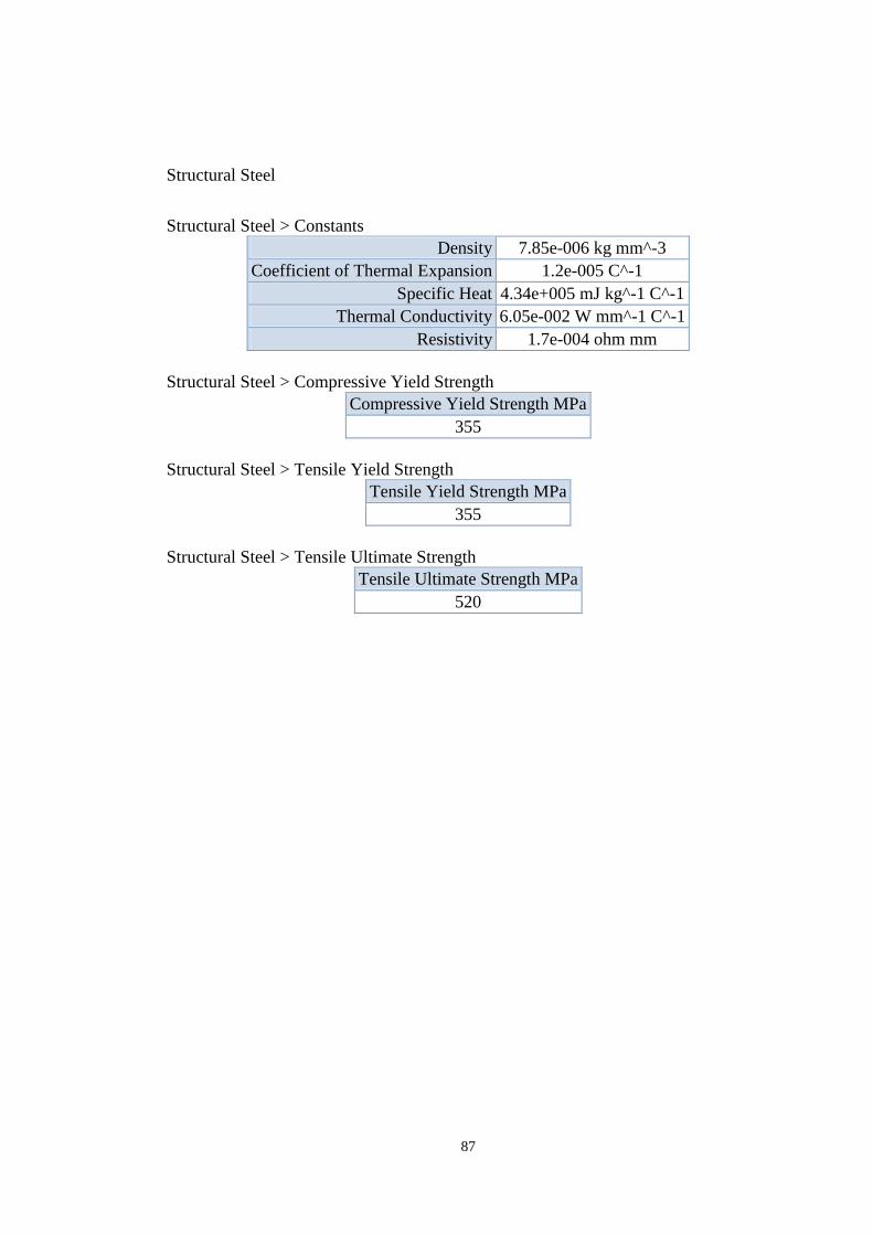
87
Structural Steel
Structural Steel > Constants
Density 7.85e-006 kg mm^-3
Coefficient of Thermal Expansion 1.2e-005 C^-1
Specific Heat 4.34e+005 mJ kg^-1 C^-1
Thermal Conductivity 6.05e-002 W mm^-1 C^-1
Resistivity 1.7e-004 ohm mm
Structural Steel > Compressive Yield Strength
Compressive Yield Strength MPa
355
Structural Steel > Tensile Yield Strength
Tensile Yield Strength MPa
355
Structural Steel > Tensile Ultimate Strength
Tensile Ultimate Strength MPa
520
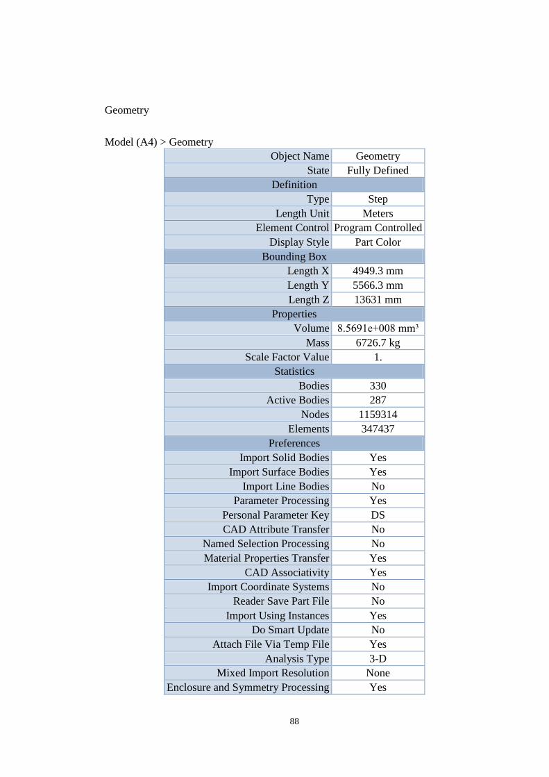
88
Geometry
Model (A4) > Geometry
Object Name Geometry
State Fully Defined
Definition
Type Step
Length Unit Meters
Element Control Program Controlled
Display Style Part Color
Bounding Box
Length X 4949.3 mm
Length Y 5566.3 mm
Length Z 13631 mm
Properties
Volume 8.5691e+008 mm³
Mass 6726.7 kg
Scale Factor Value 1.
Statistics
Bodies 330
Active Bodies 287
Nodes 1159314
Elements 347437
Preferences
Import Solid Bodies Yes
Import Surface Bodies Yes
Import Line Bodies No
Parameter Processing Yes
Personal Parameter Key DS
CAD Attribute Transfer No
Named Selection Processing No
Material Properties Transfer Yes
CAD Associativity Yes
Import Coordinate Systems No
Reader Save Part File No
Import Using Instances Yes
Do Smart Update No
Attach File Via Temp File Yes
Analysis Type 3-D
Mixed Import Resolution None
Enclosure and Symmetry Processing Yes
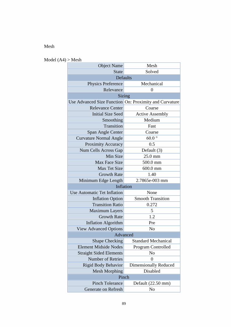
89
Mesh
Model (A4) > Mesh
Object Name Mesh
State Solved
Defaults
Physics Preference Mechanical
Relevance 0
Sizing
Use Advanced Size Function On: Proximity and Curvature
Relevance Center Coarse
Initial Size Seed Active Assembly
Smoothing Medium
Transition Fast
Span Angle Center Coarse
Curvature Normal Angle 60.0 °
Proximity Accuracy 0.5
Num Cells Across Gap Default (3)
Min Size 25.0 mm
Max Face Size 500.0 mm
Max Tet Size 600.0 mm
Growth Rate 1.40
Minimum Edge Length 2.7865e-003 mm
Inflation
Use Automatic Tet Inflation None
Inflation Option Smooth Transition
Transition Ratio 0.272
Maximum Layers 5
Growth Rate 1.2
Inflation Algorithm Pre
View Advanced Options No
Advanced
Shape Checking Standard Mechanical
Element Midside Nodes Program Controlled
Straight Sided Elements No
Number of Retries 0
Rigid Body Behavior Dimensionally Reduced
Mesh Morphing Disabled
Pinch
Pinch Tolerance Default (22.50 mm)
Generate on Refresh No
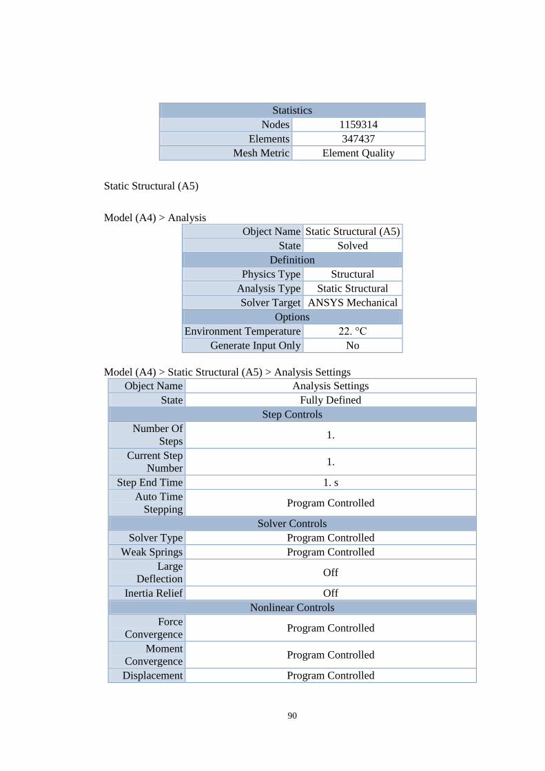
90
Statistics
Nodes 1159314
Elements 347437
Mesh Metric Element Quality
Static Structural (A5)
Model (A4) > Analysis
Object Name Static Structural (A5)
State Solved
Definition
Physics Type Structural
Analysis Type Static Structural
Solver Target ANSYS Mechanical
Options
Environment Temperature 22. °C
Generate Input Only No
Model (A4) > Static Structural (A5) > Analysis Settings
Object Name Analysis Settings
State Fully Defined
Step Controls
Number Of
Steps 1.
Current Step
Number 1.
Step End Time 1. s
Auto Time
Stepping Program Controlled
Solver Controls
Solver Type Program Controlled
Weak Springs Program Controlled
Large
Deflection Off
Inertia Relief Off
Nonlinear Controls
Force
Convergence Program Controlled
Moment
Convergence Program Controlled
Displacement Program Controlled
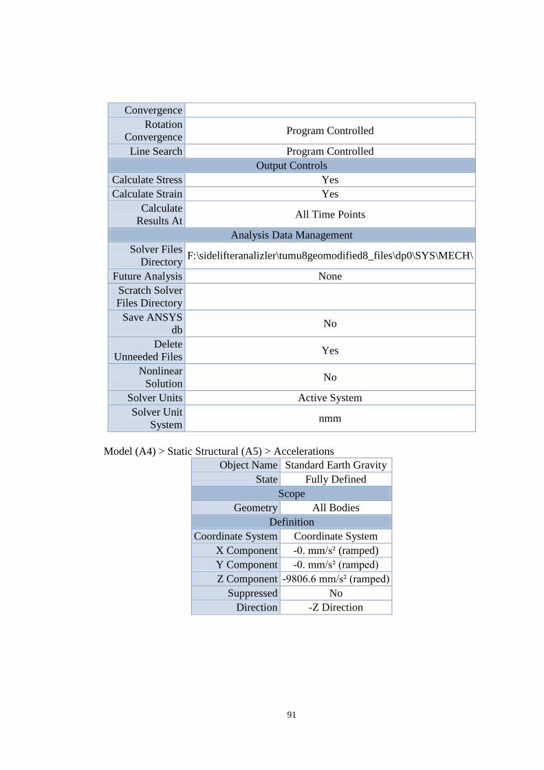
91
Convergence
Rotation
Convergence Program Controlled
Line Search Program Controlled
Output Controls
Calculate Stress Yes
Calculate Strain Yes
Calculate
Results At All Time Points
Analysis Data Management
Solver Files
Directory F:\sidelifteranalizler\tumu8geomodified8_files\dp0\SYS\MECH\
Future Analysis None
Scratch Solver
Files Directory
Save ANSYS
db No
Delete
Unneeded Files Yes
Nonlinear
Solution No
Solver Units Active System
Solver Unit
System nmm
Model (A4) > Static Structural (A5) > Accelerations
Object Name Standard Earth Gravity
State Fully Defined
Scope
Geometry All Bodies
Definition
Coordinate System Coordinate System
X Component -0. mm/s² (ramped)
Y Component -0. mm/s² (ramped)
Z Component -9806.6 mm/s² (ramped)
Suppressed No
Direction -Z Direction
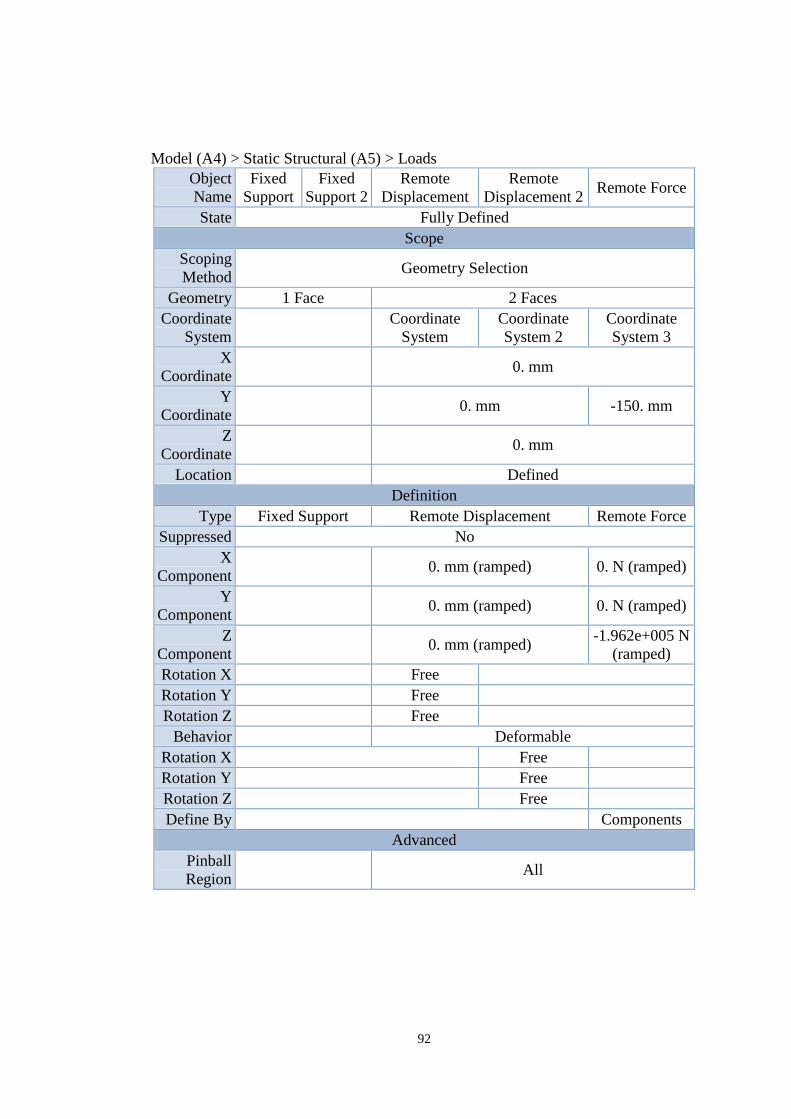
92
Model (A4) > Static Structural (A5) > Loads
Object
Name
Fixed
Support
Fixed
Support 2
Remote
Displacement
Remote
Displacement 2 Remote Force
State Fully Defined
Scope
Scoping
Method Geometry Selection
Geometry 1 Face 2 Faces
Coordinate
System
Coordinate
System
Coordinate
System 2
Coordinate
System 3
X
Coordinate 0. mm
Y
Coordinate 0. mm -150. mm
Z
Coordinate 0. mm
Location Defined
Definition
Type Fixed Support Remote Displacement Remote Force
Suppressed No
X
Component 0. mm (ramped) 0. N (ramped)
Y
Component 0. mm (ramped) 0. N (ramped)
Z
Component 0. mm (ramped)
-1.962e+005 N
(ramped)
Rotation X Free
Rotation Y Free
Rotation Z Free
Behavior Deformable
Rotation X Free
Rotation Y Free
Rotation Z Free
Define By Components
Advanced
Pinball
Region All
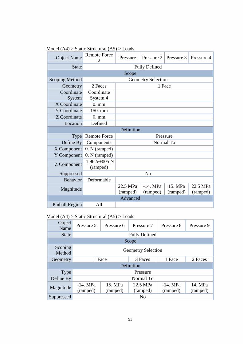
93
Model (A4) > Static Structural (A5) > Loads
Object Name Remote Force
2 Pressure Pressure 2 Pressure 3 Pressure 4
State Fully Defined
Scope
Scoping Method Geometry Selection
Geometry 2 Faces 1 Face
Coordinate
System
Coordinate
System 4
X Coordinate 0. mm
Y Coordinate 150. mm
Z Coordinate 0. mm
Location Defined
Definition
Type Remote Force Pressure
Define By Components Normal To
X Component 0. N (ramped)
Y Component 0. N (ramped)
Z Component -1.962e+005 N
(ramped)
Suppressed No
Behavior Deformable
Magnitude 22.5 MPa
(ramped)
-14. MPa
(ramped)
15. MPa
(ramped)
22.5 MPa
(ramped)
Advanced
Pinball Region All
Model (A4) > Static Structural (A5) > Loads
Object
Name Pressure 5 Pressure 6 Pressure 7 Pressure 8 Pressure 9
State Fully Defined
Scope
Scoping
Method Geometry Selection
Geometry 1 Face 3 Faces 1 Face 2 Faces
Definition
Type Pressure
Define By Normal To
Magnitude -14. MPa
(ramped)
15. MPa
(ramped)
22.5 MPa
(ramped)
-14. MPa
(ramped)
14. MPa
(ramped)
Suppressed No
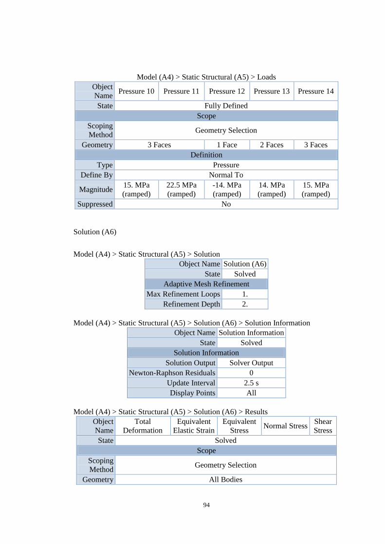
94
Model (A4) > Static Structural (A5) > Loads
Object
Name Pressure 10 Pressure 11 Pressure 12 Pressure 13 Pressure 14
State Fully Defined
Scope
Scoping
Method Geometry Selection
Geometry 3 Faces 1 Face 2 Faces 3 Faces
Definition
Type Pressure
Define By Normal To
Magnitude 15. MPa
(ramped)
22.5 MPa
(ramped)
-14. MPa
(ramped)
14. MPa
(ramped)
15. MPa
(ramped)
Suppressed No
Solution (A6)
Model (A4) > Static Structural (A5) > Solution
Object Name Solution (A6)
State Solved
Adaptive Mesh Refinement
Max Refinement Loops 1.
Refinement Depth 2.
Model (A4) > Static Structural (A5) > Solution (A6) > Solution Information
Object Name Solution Information
State Solved
Solution Information
Solution Output Solver Output
Newton-Raphson Residuals 0
Update Interval 2.5 s
Display Points All
Model (A4) > Static Structural (A5) > Solution (A6) > Results
Object
Name
Total
Deformation
Equivalent
Elastic Strain
Equivalent
Stress Normal Stress
Shear
Stress
State Solved
Scope
Scoping
Method Geometry Selection
Geometry All Bodies
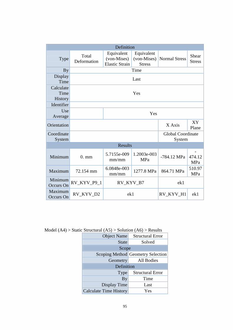
95
Definition
Type Total
Deformation
Equivalent
(von-Mises)
Elastic Strain
Equivalent
(von-Mises)
Stress
Normal Stress Shear
Stress
By Time
Display
Time Last
Calculate
Time
History
Yes
Identifier
Use
Average Yes
Orientation X Axis XY
Plane
Coordinate
System
Global Coordinate
System
Results
Minimum 0. mm 5.7155e-009
mm/mm
1.2003e-003
MPa -784.12 MPa
-
474.12
MPa
Maximum 72.154 mm 6.0848e-003
mm/mm 1277.8 MPa 864.71 MPa
510.97
MPa
Minimum
Occurs On RV_KYV_P9_1 RV_KYV_B7 ek1
Maximum
Occurs On RV_KYV_D2 ek1 RV_KYV_H1 ek1
Model (A4) > Static Structural (A5) > Solution (A6) > Results
Object Name Structural Error
State Solved
Scope
Scoping Method Geometry Selection
Geometry All Bodies
Definition
Type Structural Error
By Time
Display Time Last
Calculate Time History Yes
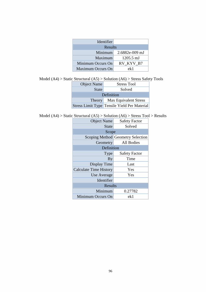
96
Identifier
Results
Minimum 2.6882e-009 mJ
Maximum 1205.5 mJ
Minimum Occurs On RV_KYV_B7
Maximum Occurs On ek1
Model (A4) > Static Structural (A5) > Solution (A6) > Stress Safety Tools
Object Name Stress Tool
State Solved
Definition
Theory Max Equivalent Stress
Stress Limit Type Tensile Yield Per Material
Model (A4) > Static Structural (A5) > Solution (A6) > Stress Tool > Results
Object Name Safety Factor
State Solved
Scope
Scoping Method Geometry Selection
Geometry All Bodies
Definition
Type Safety Factor
By Time
Display Time Last
Calculate Time History Yes
Use Average Yes
Identifier
Results
Minimum 0.27782
Minimum Occurs On ek1

97
Structural Steel
Structural Steel > Constants
Density 7.85e-006 kg mm^-3
Coefficient of Thermal Expansion 1.2e-005 C^-1
Specific Heat 4.34e+005 mJ kg^-1 C^-1
Thermal Conductivity 6.05e-002 W mm^-1 C^-1
Resistivity 1.7e-004 ohm mm
Structural Steel > Compressive Yield Strength
Compressive Yield Strength MPa
355
Structural Steel > Tensile Yield Strength
Tensile Yield Strength MPa
355
Structural Steel > Tensile Ultimate Strength
Tensile Ultimate Strength MPa
520
Related Documents