117 Chapter 6 Aircraft Propulsion Dava J. Newman 6.1 | INTRODUCTION V ehicles require a means by which to achieve motion, a way to thrust themselves to accelerate and then counteract frictional forces from motion. In this process, an engine converts potential energy to kinetic energy and also replenishes the kinetic energy that is lost to heat due to friction. For an aircraft, the most eff i- cient way to mov e is to use the air around it. In this chapter , we look at the way aircraft engines work. All aircraft propulsion systems are based on the principle of reaction of airflow through an engine of some sort. It may also be thought of as the acceleration of air flowing through the aircraft engine. Air-breathing propulsion systems require a source of power and the means for accelerating airflow. The three primary sources of power or energy for propulsion are I Hydrocarbon fuels and a heat engine. I Batteries and an electric motor. I Solar cells and an electric motor. A fourth type of po wer source for pr opulsion is human po wer (see the CD- ROM for world-record-breaking aircraft and hydrofoil designs that rely on human power plants). Human- powered aircr aft are propeller -powered, but the “engine” is a human whose po wer output is t ransferred t o the propeller using bicycle gearing. The two means for accelerating an airflow presented in this chapter are through propellers and jet expansion. Rocket engines are beyond the scope of this chapter, but are mentioned briefly later . The design of dif ferent typ es of engines satisf ies vari ous needs. Common goals of all propulsion systems are to provide sufficient thrust to balance the drag of the aircraft and to exceed the drag of the airplane for accelerated flight. Commercial transport aircraft and cargo planes place a premium on high engine Pathfinder.jpg, NASA- jet.GIF , GE_ YJ-93.jpg Human powered flight.

Welcome message from author
This document is posted to help you gain knowledge. Please leave a comment to let me know what you think about it! Share it to your friends and learn new things together.
Transcript
7/28/2019 6. Aircraft Propulsion
http://slidepdf.com/reader/full/6-aircraft-propulsion 1/30
C h a p t e r
6Aircraft PropulsionDava J. Newman
6.1 | INTRODUCTION
Vehicles require a means by which to achieve motion, a way to thrust themselves
to accelerate and then counteract frictional forces from motion. In this process,
an engine converts potential energy to kinetic energy and also replenishes the
kinetic energy that is lost to heat due to friction. For an aircraft, the most effi-
cient way to move is to use the air around it. In this chapter, we look at the way
aircraft engines work. All aircraft propulsion systems are based on the principle
of reaction of airflow through an engine of some sort. It may also be thought of
as the acceleration of air flowing through the aircraft engine.
Air-breathing propulsion systems require a source of power and the means
for accelerating airflow. The three primary sources of power or energy forpropulsion are
I Hydrocarbon fuels and a heat engine.
I Batteries and an electric motor.
I Solar cells and an electric motor.
A fourth type of power source for propulsion is human power (see the CD-
ROM for world-record-breaking aircraft and hydrofoil designs that rely on
human power plants). Human-powered aircraft are propeller-powered, but the
“engine” is a human whose power output is transferred to the propeller using
bicycle gearing.
The two means for accelerating an airflow presented in this chapter arethrough propellers and jet expansion. Rocket engines are beyond the scope of
this chapter, but are mentioned briefly later.
The design of different types of engines satisfies various needs. Common
goals of all propulsion systems are to provide sufficient thrust to balance the
drag of the aircraft and to exceed the drag of the airplane for accelerated flight.
Commercial transport aircraft and cargo planes place a premium on high engine
Pathfinder.jpg, NA
jet.GIF, GE_
YJ-93.jpg
Human powered
flight.

7/28/2019 6. Aircraft Propulsion
http://slidepdf.com/reader/full/6-aircraft-propulsion 2/30
118 C H A P T E R 6 Aircraft Propulsion
*(edited from [36])
efficiency and low fuel usage, while fighter planes and experimental high-speed
aircraft require high excess thrust to accelerate quickly. For these aircraft, engine
efficiency is not as important as very high thrust.
6.2 | THE PROPELLER*Thrust is the force that moves an aircraft through the air and is generated by the
propulsion system. Different types of propulsion systems develop thrust in dif-
ferent ways, although it is usually generated through some application of New-
ton’s third law of motion (see Section 9.3, “Newton’s Laws of Motion and Grav-
itation,” for more details). In his 1687 publication The Mathematical Principles
of Natural Philosophy, commonly known as the Principia, Newton states
To every action there is an equal and opposite reaction. In other words, if particle 1
acts on particle 2 with a force F12 in a direction along the line adjoining the parti-
cles; while particle 2 acts on particle 1 with a force F 21, then F12 ϭ F21.
For 40 years following the Wright brothers’ first flight, airplanes used inter-
nal combustion engines to turn propellers to generate thrust. Most general avia-
tion or private airplanes are powered by propellers and internal combustion
engines similar to automobile engines. The engine takes air from the surround-
ings, mixes it with fuel, burns the fuel, thereby releasing the energy in the fuel
and uses the heated gas exhaust to move a piston that is attached to a crankshaft
In the automobile, the shaft is used to turn the wheels of the car whereas in an
airplane, the shaft turns a propeller.
What is the difference between an engine and a motor? An engine produces
work from heat (combustion), and a motor typically produces work from the
conversion of electrical energy to mechanical energy. Combustion engines are
further discussed in this chapter. Motors are highlighted in Chapter 12, “Design:Lighter-Than-Air (LTA) Vehicle Module,” where batteries supply the electrical
energy that is converted to the mechanical energy that turns the propellers to pro-
pel the lighter-than-air vehicles. State-of-the-art, solar-powered electric aircraft
also use propellers.
6.2.1 Fundamental Equations GoverningPropeller Propulsion
The details of propeller propulsion are complicated, but fundamental insights
can be gleaned from physics, specifically, the principles of conservation ofmomentum and energy. The complexity stems from the fact that the propeller
acts as a rotating wing, creating a lift force because of its motion through the air
For propeller-powered aircraft, the gas is accelerated as the surrounding air
passes through the propeller. The actual process of combustion in the engine pro-

7/28/2019 6. Aircraft Propulsion
http://slidepdf.com/reader/full/6-aircraft-propulsion 3/30
S E C T I O N 6 . 2 The Propeller
Figure 6.1 | Propeller schematic showing the envelopeof a moving air mass where inlet velocity is u 0 and exitvelocity is u e .
Engine ue
uo
vides very little thrust. Rather, the thrust is produced by the propeller. Propellers
have two, three, or four blades that are typically long and thin. A perpendicular
cut through the blade reveals the propeller’s airfoil shape. Because they are
radial blades, the tip moves faster than the hub. Twisted blades offer a proven
design for maximum propeller efficiency. The angle of attack of the propeller
airfoils varies from the hub to the tip with lower angles at the tip, which makes
precisely analyzing the airflow through the entire propeller challenging.
The engine turns the propeller and does work on the airflow, causing a sig-
nificant change in pressure across the propeller disk. The propeller acts as a
rotating wing, and in Chapter 3, “Aerodynamics,” we learned that the pressure
over the top of a lifting wing is lower than the pressure underneath the wing. The
spinning propeller sets up a pressure lower than freestream in front of the pro-
peller and higher than freestream behind the propeller.
A schematic of a propeller propulsion system is shown in Figure 6.1. The
thrust force depends on the mass flow through the propeller and the corre-
sponding change in velocity as the air moves across the propeller. The mass
flow through the propulsion system is a constant. Therefore, the physics behind
propeller-driven flight relies on Newton’s equations of motion and the conser-
vation of energy and momentum. Recall that Newton’s second law, F ϭ ma, is
the time rate of change of momentum. As applied to our propeller, force (thrust
in this case) ϭ (mass/time)(momentum/mass). From the conservation of
momentum, the force or thrust is equal to the mass flow times the difference
between the exit and inlet velocities, written as
[6.1]F ϭ m# 1ue Ϫ u0 2

7/28/2019 6. Aircraft Propulsion
http://slidepdf.com/reader/full/6-aircraft-propulsion 4/30
120 C H A P T E R 6 Aircraft Propulsion
where u0 is the inlet velocity, ue is the exit velocity, and m is the change in mass(the mass flow). The exit velocity is higher than the inlet velocity because thepropeller accelerates the air. In reality, the thrust depends on the inlet velocity
but we assume that for our purposes the propeller is moving much faster (meas-ured in revolutions per minute) than our propeller aircraft.
From conservation of energy, ideal propeller power output is equal to the
kinetic energy flux across the propeller. This change in energy is the change inmass times the difference between the exit and inlet velocities
[6.2]
where P denotes propeller power. We define propeller efficiency as a ratio of use-
ful work to input power, or
where work is the force (thrust in this case) F times the inlet velocity u0, and thepower that goes into the engine is P. Efficiencies are often denoted by the Greeksymbol eta (h):
[6.3]
Substituting Equation (6.1) and Equation (6.2) into Equation (6.3) yields
[6.4]
More generally, we call this the propulsive efficiency, or h p
.
To attain a high efficiency (hϳ 1), we want to drive ue S u0. However, fromthe momentum equation, at higher efficiencies we need a larger mass flow toachieve a desired thrust. Thus, there are certain real-world limits on how effi-
cient an aircraft engine can be.Rewriting Equation (6.1) as
[6.5]
leads to the relation for propulsive efficiency, thrust, mass flow, and velocities
shown in Figure 6.2.Realizing that our engine is a combustion engine, which is often referred to
as a heat engine, we need to include thermal effects as well as propeller effi-ciencies. We define thermal efficiency as
[6.6]
where P is power, m f is the mass flow of fuel, and Q is the heating value of the
fuel.
ht ϭP
m# f Q
F
m#u0
ϭue
u0
Ϫ 1
hprop ϭ2u0
ue ϩ u0
hprop ϭFu0
P
Propeller efficiency ϭuseful work
input powerϭ
Fu0
P
P ϭ m#
a ue2
2Ϫ
u02
2b ϭ m
#
2 1ue Ϫ u0 2 1ue ϩ u0 2

7/28/2019 6. Aircraft Propulsion
http://slidepdf.com/reader/full/6-aircraft-propulsion 5/30
S E C T I O N 6 . 2 The Propeller
Figure 6.2 | Propulsive efficiency relation.
1
10
5 10
F muo
pη
ue
uo
A combustion engine’s thermal efficiency is governed by thermodynamics.We can show that the thermal efficiency is less than the Carnot (ideal) efficiency.
[6.7]
For the atmosphere the mean temperature T 0 ranges between 200 and 300 K. Forhydrocarbon fuels the source temperature is typically
Therefore,
and the actual thermal efficiency is closer to
Finally, we define the overall efficiency as thermal efficiency times propul-
sive efficiency, or the ratio of
as Equation (6.8) shows.
[6.8]hoverall ϭ ht h p ϭFu0
m# f Q
Power to push the aircraft
Energy flow in the fuel
ht ϭ 0.5
hc 6 1 Ϫ200
3,000Ϸ 0.9
T source 6 3,000 K
ht Յ hc ϭ 1 ϪT 0
T source
7/28/2019 6. Aircraft Propulsion
http://slidepdf.com/reader/full/6-aircraft-propulsion 6/30
122 C H A P T E R 6 Aircraft Propulsion
*(edited from [36])
To attain higher flight velocities, we turn to jet engines. After World War II, jetengines gained popularity, and a transition between propellers and jets can beseen on some aircraft where jet engines are used to turn propellers. This propul-
sion system is called a turboprop, where the main thrust comes from the pro-pellers, which are turned by turbine engines (see Section 6.4.3, “How Does aTurboprop Work?” ) [36].
6.3 | THE ILLUSTRATED JET ENGINE*
There are several different types of jet engines, often referred to as gas turbine
engines, but all turbine engines share the same core elements: an inlet, compres-sor, burner, turbine, and nozzle. The inlet brings freestream air into the enginewhich sits upstream of the compressor. The compressor increases the pressure of
the incoming air before it enters the burner (sometimes called the combustor)Fuel is combined with high-pressure air and burned at this stage of the engine.The resulting high-temperature exhaust gas is used to turn the power turbine and
to produce thrust when passed through a nozzle. The power turbine is locateddownstream of the burner and extracts energy from the hot flow, which is thenused to turn the compressor. The nozzle is downstream of the power turbine.
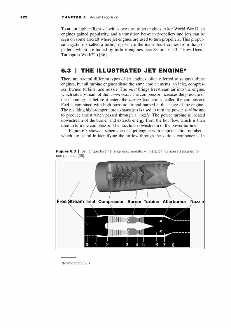
Figure 6.3 shows a schematic of a jet engine with engine station numbers,which are useful in identifying the airflow through the various components. In
Figure 6.3 | Jet, or gas turbine, engine schematic with station numbers assigned tocomponents [36].

7/28/2019 6. Aircraft Propulsion
http://slidepdf.com/reader/full/6-aircraft-propulsion 7/30
S E C T I O N 6 . 3 The Illustrated Jet Engine
NASA Glenn
animated turbine
engines.
Figure 6.4 | Typical inlet designs for subsonic and supersonic jet engines [36].
addition, the figure shows an afterburner, which most modern fighter aircraftincorporate into their engine design to fly faster than the speed of sound, or atsupersonic speed. Details of the core components are given, followed by a
description of six types of jet engines:
I Turbojets.
I Turbofans.I Turboprops.
I Afterburning turbojets.
I Ramjets.
I Ultra high bypass engines.
6.3.1 Inlet or Intake
The freestream air enters the gas turbine engine at the inlet, also referred to asthe intake. While the inlet does no work on the flow, there are important engi-
neering design features to this component. Inlets come in a variety of shapes andsizes, usually dictated by the speed of the aircraft (see Figure 6.4). For aircraftthat cannot go faster than the speed of sound, simple, straight, short inlet designswork well (e.g., for most commercial and cargo aircraft). The surface of the inlet
is a continuous smooth curve where the very front (most upstream portion) iscalled the highlight, or the inlet lip. A subsonic aircraft has an inlet with a relativelythick lip. An inlet for a supersonic aircraft, on the other hand, has a relatively sharp

7/28/2019 6. Aircraft Propulsion
http://slidepdf.com/reader/full/6-aircraft-propulsion 8/30
124 C H A P T E R 6 Aircraft Propulsion
lip. The design of a sharpened lip minimizes performance losses from shockwaves that occur during supersonic flight. For a supersonic aircraft, the inletmust slow the flow down to subsonic speeds before the air reaches the compres-
sor. Some supersonic inlets use an axisymmetric central cone to shock the flowdown to subsonic speeds (Figure 6.4, top right), while other inlets use flat hingedplates to generate compression shocks with the resulting inlet geometry having
a rectangular cross section (Figure 6.4, bottom left). This kind of inlet is seen onthe F-14 and F-15 fighter aircraft. There are additional, more exotic inlet shapesused on some aircraft for a variety of reasons.
An inlet, or intake, must operate efficiently over the entire flight envelope ofthe aircraft. At very low aircraft speeds, or when it is stationary on the runwayfreestream air is pulled into the engine by the compressor. At high speeds, a good
inlet design allows the aircraft to maneuver to high angles of attack without dis-rupting flow to the compressor. Because the inlet is so important to overall air-craft operation, it is usually designed and tested by the airframe company as well
as the engine manufacturer.Because the inlet does no thermodynamic work, the total temperature
through the inlet is constant. Referring to the station numbers on Figure 6.3, thetemperature ratio between the freestream (denoted at stage 0) and the inletboundary with the compressor is
[6.9]
However, the total pressure across the inlet can change due to aerodynamic
flow effects, which are characterized by the inlet (total) pressure recovery (IPR)The IPR measures how much of the freestream flow conditions are “recovered,”or the ratio in total pressure between stages 2 and 0 across the inlet lip at stage1. The pressure recovery depends on a wide variety of factors, including the
shape of the inlet, the speed of the aircraft, the airflow demands of the engineand aircraft maneuvers. Analytically, the IPR is a function of inlet efficiency hi
which is represented as
[6.10]
and Mach number M is the ratio of velocity to speed of sound [see Equation (3.26)];
therefore, IPR is given as
[6.11]
[6.12]
6.3.2 Compressor
In the turbine engine, air flows from the inlet to the compressor where the pres-sure of the incoming air is increased before it enters the combustor. Work is per-
IPR ϭ p2
p0
ϭ hi 31 Ϫ 0.0751 M Ϫ 1 2 1.35 4 for M 7 1
IPR ϭ p2
p0
ϭ hi1 for M 6 1
hi ϭ p2
p1
T 2
T 0ϭ 1

7/28/2019 6. Aircraft Propulsion
http://slidepdf.com/reader/full/6-aircraft-propulsion 9/30
S E C T I O N 6 . 3 The Illustrated Jet Engine
formed by the compressor to increase the air pressure. The two main types of compressors are axial and centrifugal. In an axial compressor the flow travels par-allel to the axis of rotation (i.e., in the axial direction). In a centrifugal compres-
sor the airflow is turned perpendicular to the axis of rotation. The very first jetengines used centrifugal compressors, and they are still used on small turbojetsand turboshaft engines and as pumps on rocket engines. Modern large turbojet
and turbofan engines usually employ axial compressors. An average, single-stage,centrifugal compressor increases the airflow pressure by a factor of 4. In the cen-trifugal compressor, the additional pressure increase results from turning the flow
radially. A similar single-stage axial compressor increases the pressure by only afactor of 1.2, but several stages can be easily linked together, producing a multi-stage axial compressor. In the multistage compressor the pressure is multiplied
from stage to stage (or row to row) (8 stages at 1.2 per stage gives a factor of 4.3).It is much more difficult to produce an efficient multistage centrifugal compres-sor because the flow must be ducted back to the axis at each stage. In the axial
compressor, cascades of small airfoils are mounted on a shaft that turns at a highvelocity. Because the flow is turned perpendicular to the axis, an engine with a
centrifugal compressor tends to be wider (greater cross-sectional area) than a cor-responding axial compressor. The greater cross section creates additional unde-sirable drag. For all these reasons, most high-compression jet engines incorporate
multistage axial compressor designs. If only a moderate amount of compressionis required, the best design choice is a centrifugal compressor.
The work that the pressure exerts on the flow is a function of pressure and
temperature. The pressure increase metric is the compressor pressure ratio, orCPR, which is the ratio of the air pressure exiting the compressor to the air pres-sure entering the compressor (always Ͼ 1). Using the station numbers of Figure
6.3, the CPR is equal to the pressure at point 3 ( p3) divided by point 2 ( p2). Thecompressor pressure ratio is related to the temperature at the entrance and exit,and the temperature, in turn, is related to the total pressure for a compressible
flow, given as
[6.13]
where CPR is the compressor pressure ratio, p is pressure at stations 3 and 2, T
is temperature at stations 3 and 2, and g is a gas property, namely, the specificheat ratio (g Ϸ 1.4 for air). The work of the compressor per mass flow can bequantified as
[6.14]
where c is a constant and represents the specific heat of a gas, T 2 is the temper-
ature at the compressor entrance, and hc is the compressor efficiency. The effi-ciency factor is included to account for the actual performance of the compres-
sor as opposed to the ideal performance. To achieve a desired design CPR, thecompressor inefficiency must be overcome, and the necessary work is provided
W comp ϭ
cT 2
hc
1CPR1gϪ
12>g Ϫ 1 2
CPR ϭ p3
p2
ϭT 3
g>1gϪ12 T 2

7/28/2019 6. Aircraft Propulsion
http://slidepdf.com/reader/full/6-aircraft-propulsion 10/30
126 C H A P T E R 6 Aircraft Propulsion
Figure 6.5 | The components of the burner, or combustor, of a gas turbine engine [36].
by the power turbine, which is connected to the compressor by the central shaftThe thermal effects in compressors are significant. In fact, on some engines, thetemperature at the exit of the compressor becomes a design constraint (i.e., a fac-
tor limiting the engine performance) due to temperature limits on the compres-sor material, especially the last compressor stage.
6.3.3 Burner or Combustor
The burner is where combustion occurs, and it is often referred to as the combus-tor of the gas turbine engine. Fuel is combined with the high-pressure air coming
out of the compressor, and combustion occurs. The resulting high-temperatureexhaust gas is used to turn the power turbine and eventually to produce thrustafter passing through the nozzle. The burner is located between the compressor
and the power turbine (see Figure 6.5). The burner is arranged as an annulus (i.e.,it is doughnut-shaped). The central engine shaft that connects the turbine and
compressor passes through the hole. Burners must be made from materials thatcan withstand the high temperatures of combustion. There is usually an outer
casing and an inner liner. The liner is often perforated to enhance mixing of thefuel and air. The three main types of combustors are annular, with a liner inside
the outer casing (peeled open in Figure 6.5); a can, which is a tubular designwhere each can has a liner and a casing; and a hybrid can-annular, where the cas-ing is annular and the liner is can-shaped. Many modern burners incorporate

7/28/2019 6. Aircraft Propulsion
http://slidepdf.com/reader/full/6-aircraft-propulsion 11/30
S E C T I O N 6 . 3 The Illustrated Jet Engine
annular designs, whereas the can design is older, but offers the flexibility of modular cans. The advantages of the can-annular burner design are that the indi-vidual cans are more easily designed and tested, and the casing is annular. All
three designs are found in modern gas turbines.The details of mixing and burning the fuel are complex. For our purposes,
we consider the burner as simply the place where combustion occurs and where
the working fluid (air) temperature is raised with a slight decrease in pressure.The burning occurs at a higher pressure than freestream because of the action of the compressor. The pressure in the burner remains nearly constant during burn-
ing, decreasing by only 1 to 2 percent. Using the station numbers from Figure6.3, the burner pressure ratio (BPR) is equal to the pressure at point 4 ( p4)divided by that at point 3 ( p3), or
[6.15]
The thermodynamics of the burner are different from those of the compressorand power turbine engine components because in the burner, heat is released inthe combustion process. In the compressor and turbine, no heat enters; therefore,
the pressure and temperature are related, and the energy equation determines thetemperature change. The energy output of the burner stage is desired. Since fuel
is added in the burner domain, we account for the added mass of the fuel byusing a ratio f of fuel to air mass flow. The heat release Q depends on the par-ticular fuel that is being burned and is determined experimentally. The burner
has an efficiency factor hb, just as the compressor stage does, to account forlosses during burning. The fuel-to-air ratio of the burner is temperature- and gas-dependent and can be quantified as
[6.16]
where denotes the mass flow of fuel, Q is the heating constant, c representsthe average specific heat, T 3 is the temperature at the burner entrance, T 4 is thetemperature at the burner exit, and hb is the burner efficiency. This ratio is very
important for determining overall aircraft performance. Material selection anddesign constraints appear once again when we consider the maximum burnerexit temperature (T 4 ). If the engine is run hotter than the maximum temperature
design specification, damage can result to both the burner and the turbine. Theburner entrance temperature (T 3 ) is determined by the compressor and the exter-nal flow conditions. The fuel heating value Q is known for the particular fuel
being used, and the specific heat coefficient is a known property of air. We solve
Equation (6.16) for the value of the fuel-to-air ratio, which allows us to preciselydetermine the engine’s specific fuel consumption. As explained in Chapter 4,“Aircraft Performance,” the specific fuel consumption factors into the maximumrange over which an aircraft can fly.
How much thrust an engine generates is important, but how much fuel isused to generate that thrust is sometimes more important. Engineers use an effi-ciency factor, called thrust specific fuel consumption (TSFC), to characterize an
m# f
f ϭm# f
m# ϭ
1T 4>T 3 2 Ϫ 1
hbQ> 1cT 3 2 Ϫ T 4>T 3
BPR ϭ p4
p3
ϳ 1

7/28/2019 6. Aircraft Propulsion
http://slidepdf.com/reader/full/6-aircraft-propulsion 12/30
128 C H A P T E R 6 Aircraft Propulsion
Figure 6.6 | Power turbine component of a jet engine [36].
engine’s fuel efficiency. The fuel consumption or TSFC is “how much fuel theengine burns each hour.” Propulsion engineers often refer to an engine’s specificthrust, which is the thrust produced per mass of air. The thrust of TSFC is
included to indicate that we are talking about gas turbine engines.
6.3.4 Power Turbine
All gas turbine engines have a power turbine located downstream of the burner toextract energy from the hot flow and to use that energy to turn the compressor
Work is done on the power turbine by the flow. The turbine is composed of tworows of small airfoil-shaped blades. The various parts of an axial turbine includethe inner shaft that rotates at very high speeds—the rotor —and the other row that
remains stationary—the stator. The turbine is linked to the compressor by theshaft, and the combination of the shaft, compressor, and turbine is called the turbo-
machinery. The stators keep the flow from spiraling around the axis by bringing
the flow back parallel to the axis. Depending on the engine type, there may be mul-tiple turbine stages present in the engine. Turbofan and turboprop engines usually
employ a separate turbine and shaft to power the fan and gearbox, respectively, andare termed a two-spool engine. Three-spool configurations exist for some high-performance engines where an additional turbine and shaft power separate parts of
the compressor. There are many interesting turbine design details (see Figure 6.6)

7/28/2019 6. Aircraft Propulsion
http://slidepdf.com/reader/full/6-aircraft-propulsion 13/30
S E C T I O N 6 . 3 The Illustrated Jet Engine
The turbine extracts energy from the flow, causing a pressure drop across theturbine. The pressure gradient helps keep the flow attached to the turbine blades,and the pressure drop across a single turbine stage can be much greater than the
pressure increase across a corresponding compressor stage. A single turbinestage can be used to drive multiple compressor stages. To keep flow from leak-ing around the edges of the turbine blades, because of the higher pressure gradi-
ent, the tips of the turbine blades may be banded together. The turbine bladesexist in a much more hostile environment than compressor blades. Sitting justdownstream of the burner, the blades experience flow temperatures of several
hundred degrees Celsius (Ͼ 1,000°F). Turbine blades must, therefore, be eithermade of special metals that can withstand the heat or actively cooled. A single,actively cooled turbine blade is shown in Figure 6.6. The blade is hollow, and
cool air, which is bled off the compressor, is pumped through the blade and outthrough the small holes on the surface, to keep the surface cool.
The derivation of equations that govern how the turbine extracts energy from
the heated flow exiting the burner is given below. As the flow passes through theturbine, the total pressure and temperature are decreased. Akin to the compres-
sor pressure ratio, we measure the decrease in pressure through the turbine as theturbine pressure ratio (TPR), or the ratio of the air pressure exiting the turbineto the air pressure entering the turbine (always Ͻ 1.0). Using the station num-
bers of Figure 6.3, the TPR is equal to the pressure at point 5 ( p5) divided by thepressure at point 4 ( p4),
[6.17]
Work is done by the flow to turn the turbine and the shaft. From thermo-dynamics, the turbine work per mass of airflow W
turb
is related to the total tem-
perature at stations 4 and 5, which is also related to the total pressure for a com-pressible flow.
[6.18]
where g is the specific heat ratio (1.4 for air), c is the specific heat, and ht is the
turbine efficiency. The efficiency factor is necessary to account for the actualperformance of the turbine.
6.3.5 Connecting the Compressor and Turbine
The compressor and turbine stages have both been described individually, but theoverall jet engine system relies on the compressor and turbine working in concert.This section describes how that is accomplished through compressor–turbine
matching. The compressor and turbine are matched to ensure proper engine oper-
ations. Analytically, we represent this relationship by setting the work done by thecompressor equal to the work done by the turbine. Hence, we are ensuring the
conservation of energy. Equating Equation (6.14) and Equation (6.16) yields
W turb ϭ 1h t cT 4 2 11 Ϫ TPR1gϪ12>g 2
TPR ϭ p5
p4
ϭT 5
g>1gϪ12 T 4

7/28/2019 6. Aircraft Propulsion
http://slidepdf.com/reader/full/6-aircraft-propulsion 14/30
130 C H A P T E R 6 Aircraft Propulsion
Figure 6.7 | Gas turbine nozzles [36].
[6.19]
The work of the compressor is between stages 2 and 3, and that of the tur-bine is between stages 4 and 5. Now, solving to get an expression for the turbinepressure ratio and a relation between stage 2 of the compressor and stage 4 of
the turbine results in
[6.20]
The final stage of the gas turbine engine is the exhaust nozzle.
6.3.6 Nozzles
The gas turbine engine nozzle has three functions: to produce thrust, to conductthe exhaust gases back to the freestream, and to set the mass flow rate through the
engine. See Figure 6.7. The nozzle sits downstream of the power turbine. A noz-zle is a relatively simple device with a specific geometry through which hot gasesflow. Nozzles come in a variety of shapes and sizes depending on the mission of
the aircraft. Simple turbojets, and turboprops, often have fixed-geometry conver-gent nozzles. Turbofan engines sometimes employ a coannular nozzle where thecore flow exits the center nozzle while the fan flow exits the annular nozzle. After-
burning turbojets and turbofans often incorporate variable-geometry convergent-
TPR1gϪ12>gϭ 1 Ϫ
T 2
hcht T 4 1CPR1gϪ12>g
Ϫ 1 2
cT 2
hc
1CPR1gϪ12>g2 Ϫ 1 2 ϭ 1ht cT 4 2 11 Ϫ TPR1gϪ12>g 2

7/28/2019 6. Aircraft Propulsion
http://slidepdf.com/reader/full/6-aircraft-propulsion 15/30
S E C T I O N 6 . 3 The Illustrated Jet Engine
divergent (CD) nozzle designs where the flow first converges down to the mini-mum area, or throat, and then is expanded through the divergent section to theexit.1 The variable geometry causes these nozzles to be heavy, but provides effi-
cient engine operation over a wider airflow range than do fixed nozzles. All thenozzles we have discussed thus far are round-tube designs. Recently, however,engineers have been experimenting with nozzles with rectangular exits, allowing
the exhaust flow to be easily deflected. Changing the direction of the thrust withthe nozzle makes the aircraft much more maneuverable.
The nozzle produces the thrust and also sets the total mass flow rate through
the engine. The nozzle does no work on the flow; nonetheless, there are someimportant design features of the nozzle. Because the nozzle does no thermody-namic work, the total temperature through the nozzle is constant, and the total
pressure is constant. Recalling the station numbers from Figure 6.3, we write
[6.21]
where 5 is the turbine exit and 8 is the nozzle throat.The static pressure at the exit of the nozzle is equal to the freestream static pres-sure, unless the exiting flow is expanded to supersonic conditions (a convergent-
divergent nozzle). The nozzle pressure ratio, or NPR, is defined as the ratio of the nozzle total to static pressure and is written as
[6.22]
where p8 is the total pressure and ps8 is the static nozzle pressure, or thefreestream static pressure. The static pressure is known, but we need to solve forthe value of the nozzle total pressure, which we determine from freestream con-
ditions and the overall engine pressure ratio EPR. The EPR depends on the pres-sure ratio of all the other engine components. The EPR is defined to be the totalpressure ratio across the engine, or simply the product of the pressure ratio
across all the engine components, and is written as
[6.23]
where the compressor, burner, turbine, and nozzle stages are all represented. TheEPR can be measured for an operating engine and is easily displayed to a pilot
inside the craft, but the total pressure losses in the inlet are not contained in theEPR. Once the EPR is known, then the NPR, or static and total pressures at thenozzle, is known.
The ETR is similarly given as
[6.24]ETR ϭT 8
T 2ϭ
T 3
T 2 #
T 4
T 3 #
T 5
T 4 #
T 8
T 5
EPR ϭ p8
p2
ϭ p3
p2
# p4
p3
# p5
p4
# p8
p5
NPR ϭ p8
ps8
ϭ p8
p0
p8
p5
ϭT 8
g>1gϪ12 T 5
ϭ 1
1. An aside: Rocket engines usually incorporate a fixed-geometry CD nozzle with a much
larger divergent section than is required for a gas turbine engine.
7/28/2019 6. Aircraft Propulsion
http://slidepdf.com/reader/full/6-aircraft-propulsion 16/30
132 C H A P T E R 6 Aircraft Propulsion
from which the nozzle total temperature (T 8) is calculated. Considering theenergy equation and solving for the exit velocity, which depends on the NPR andthe nozzle total temperature, yield
[6.25]
where hn is the nozzle efficiency, which is normally very close to 1.The nozzle performance equations work just as well for rocket enginesexcept that rocket nozzles always expand the flow to some supersonic exitvelocity.
Because the nozzle conducts the hot exhaust back to the freestream, there canbe serious interactions between the engine exhaust flow and the airflow around theaircraft. On fighter aircraft, in particular, large drag penalties can occur near noz-
zle exits. A typical nozzle-afterbody configuration is shown in Figure 6.7 for an F-15 with experimental maneuvering nozzles. As with the inlet design, the externalnozzle configuration is often designed by the aircraft manufacturers whereas the
internal nozzle design is usually the responsibility of the engine manufacturer.
We now know all the necessary relations between gas turbine engine com-ponents to solve for the thrust developed by the jet engine. Given that the EPR,
the inlet losses, and the corresponding engine temperature ratio (ETR) are knownSection 6.4, “Fundamental Equations Governing Jet Engines,” provides a sum-
mary of the analysis. The analytical section is followed by a description of sixvarious engines: turbojets, turbofans, turboprops, afterburning turbojets, ramjetsand ultra high bypass engines.
6.4 | FUNDAMENTAL EQUATIONSGOVERNING JET ENGINES
We have described the gas turbine engine components and now want to solve forthe thrust developed by the entire jet engine system. All the equations necessaryto compute the thrust for a turbojet engine have been introduced and are synthe-
sized in this section. The specific thrust depends only on the exit velocity fromthe nozzle, the freestream velocity, and the fuel-to-air mass flow ratio f [givenin Equation (6.16)]. The equation for the exit velocity was developed in Section
6.3.6, “Nozzles,” and depends on the thermodynamic properties of total temper-ature in the nozzle and the nozzle pressure ratio (NPR) [given in Equation(6.22)]. The total pressure and the total temperature in the nozzle depend on the
overall engine pressure ratio and engine temperature ratio [given in Equation(6.23) and Equation (6.24)], which depend on the pressure and temperature
ratios across each of the engine components. Recall that the thrust, Equation(6.1), is governed by conservation of momentum
The exit velocity derived from the nozzle performance is
and the nozzle pressure ratio is NPR ϭ p8 / ps8 ϭ p8 / p0.
ue ϭ u8 ϭ 2 2chnT 8 31 Ϫ 11>NPR 2 1gϪ12>g 4
F ϭ m# 1ue Ϫ u0 2
ue ϭ u8 ϭ 2 2chnT 8 31 Ϫ 11>NPR 2 1gϪ12>g 4

7/28/2019 6. Aircraft Propulsion
http://slidepdf.com/reader/full/6-aircraft-propulsion 17/30
S E C T I O N 6 . 4 Fundamental Equations Governing Jet Engines
The engine core pressure and temperature are written as
The engine pressure and temperature ratios are referenced to conditions at the
compressor face, or stage 2.
where IPR was given by Equation (6.11) and Equation (6.12) for M Ͻ 1 and M
Ͼ 1, respectively. The conditions at the compressor stage depend on inlet per-formance and freestream conditions. Temperature is given by
where the total temperature at stage 0 is equivalent to the static, or freestream,temperature. The summary equations below are compressible forms for deter-mining the total pressure and temperature conditions from the corresponding
static conditions and the freestream velocity.
[6.26]
[6.27]
[6.28]
where the variable a0 is the freestream speed of sound and R is the gas constant(286 m2 /s2 /K° (or 0.286 kJ/kg/K°) for air).
Calculate the Ratio of Thrust to Mass Flow Times Velocity
Given typical values for a jet engine
Inlet velocity u 0 Ϸ 300 m/s
Heating value of the fuel Q ϭ 4.8 ϫ 107 J/kg
Thermal and propulsive efficiencies ht ϭ 0.5 and hp ϭ 0.5
Determine the difference between the inlet and exit velocity.
Determine the thrust to mass flow times the velocity ratio.
F
m #u 0ϭ
u e
u 0Ϫ 1 ϭ
700 m>s300 m>s Ϫ 1 ϭ
4
3
u e Ϫ u 0 ϭ4.8 ϫ 107 J>kg
300 m>s # 0.01 # 0.5 # 0.5 ϭ 400 m>s
Mass flow ratiom #f
m # ϭ 0.01
a0 ϭ 2 g RT 0
p0ϭ ps0
1T 0>T s02 g>1gϪ12
T 0 ϭ T s0 31 ϩ 0.51g Ϫ 1 2 u20>a2
0 4
T 0 ϭ T s0
p2 ϭ p01IPR 2 and T 2 ϭ T 0
p8 ϭ p2 1EPR 2 and T 8 ϭ T 2 1ETR 2
EXAMPLE 6.
7/28/2019 6. Aircraft Propulsion
http://slidepdf.com/reader/full/6-aircraft-propulsion 18/30
134 C H A P T E R 6 Aircraft Propulsion
Next, we would like to know how thrust varies with altitude. Using conser-vation of mass and assuming an isothermal atmosphere, we begin by writing
[6.29]
We assume that at stage 2, the compressor, the mass flow is density times veloc-ity times area A, and we substitute into Equation (6.29) for :
[6.30]
The velocity at the compressor u2 is fixed by the speed of the blades in theengine, resulting in a mass flow proportional to density r r 2.
[6.31]
where h is in meters. Therefore, the ratio of thrust at altitude to sea-level thrust is
[6.32]
Thus, we see that for a given velocity the thrust decreases exponentiallySection 6.7, “Aircraft Propulsion Simulator,” provides numerous examples andapplications of the jet engine aircraft derived in this section. Further discussion
of how jet engines actually work and design enhancements to the standard con-figuration follows.
6.4.1 How Does a Turbojet Work?
The common components of the engine have been described, so now we con-centrate on the entire engine system operation. The different types of engines
will be discussed, specifically, the turbojet, turbofan, turboprop, afterburningturbojets, ramjets, and ultra high bypass engines. The turbojet is the basic engineof the jet age. Large amounts of air surrounding the engine are continuously
brought into the engine through the inlet which then enter the compressor. Themany rows of compressor squeeze the air to many times the freestream pressure.The compressor requires air and an energy supply to operate. At the exit of the
compressor, the compressed air is forced into the burner. In the burner a small
amount of fuel is sprayed into the compressed air, is ignited, and is burned con-tinuously. A typical jet engine ratio has a 50 : 1 ratio of air mass flow to fuel
mass flow. Leaving the burner, the hot, expanding exhaust is passed through theturbine. The turbine works as a windmill and extracts energy from the expand-ing gases while the blades rotate in the flow. In a jet engine the energy extracted
by the turbine drives through a linked central shaft. The turbine depletes some
F
F sl
ϭ eϪh>7,500
r 2 1altitude2 r sl 1sea level 2 Ϸ eϪh>7,500
m#
F ϭ r 2u2 A2u 0 a ue
u 0
Ϫ 1 bm#
F ϭ m#u0 a ue
u 0
Ϫ 1 b
7/28/2019 6. Aircraft Propulsion
http://slidepdf.com/reader/full/6-aircraft-propulsion 19/30
S E C T I O N 6 . 4 Fundamental Equations Governing Jet Engines
energy from the hot exhaust, but there is sufficient energy left over to provideaircraft forward thrust by increasing the flow velocity through the nozzle—ademonstration of the action-and-reaction principle. For a jet engine, the exit
mass flow is nearly equal to the freestream mass flow, since very little fuel isadded to the stream.
The thrust equation given in Equation (6.1) contains two interesting terms.
Aerospace engineers often refer to the first term (exit mass flow rate times exitvelocity) as the gross thrust since this term is mostly associated with conditionsin the nozzle. The second term (freestream mass flow rate times freestream
velocity) is called the ram drag. For clarity, the engine thrust is then called the
net thrust. Our thrust equation indicates that net thrust equals gross thrust minusram drag.
6.4.2 How Does a Turbofan Work?
Most modern airliners use turbofan engines because of their high thrust andgood fuel efficiency. A turbofan engine is a variation of the basic gas turbine
engine, where the core engine is surrounded by a fan in the front and an addi-tional fan turbine at the rear. The fan and fan turbine are composed of many
blades, as are the core compressor and core turbine, and are connected to anadditional shaft. As with the core compressor and turbine, some of the fan bladesturn with the shaft and other blades remain stationary. The fan shaft typically
passes through the core shaft for mechanical reasons. This type of arrangementis called a two-spool engine (one spool for the fan, one spool for the core). Someadvanced engines have additional spools for even higher efficiency.
The incoming air is captured by the engine inlet. Some of the incoming airpasses through the fan and continues on into the core compressor, then into theburner, where it is mixed with fuel and combustion occurs. The hot exhaust
passes through the core and fan turbines and then out the nozzle, identical to theprocess in a basic turbojet. The fan causes additional air to flow around(bypass) the engine, just like the air through a propeller. This produces greater
thrust and reduces specific fuel consumption. Therefore, a turbofan gets someof its thrust from the core and some from the fan. The ratio between the air massthat flows around the engine and the air mass that goes through the core is
called the bypass ratio .
Because the fuel flow rate for the core is changed only a small amount by
the addition of the fan, a turbofan generates more thrust for nearly the sameamount of fuel used by the core. A turbofan is very fuel-efficient—in fact, high
bypass ratio turbofans are nearly as fuel-efficient as turboprops (discussed inSection 6.4.3). Because the fan is enclosed by the inlet and is composed of manyblades, it operates more efficiently at higher speeds than a simple propeller. Thatis why turbofans are found on high-speed transports and propellers are used on
low-speed transports. There are two types of turbofans: high bypass and lowbypass (see Figure 6.8 and Figure 6.9). High bypass turbofans have large fans in

7/28/2019 6. Aircraft Propulsion
http://slidepdf.com/reader/full/6-aircraft-propulsion 20/30
136 C H A P T E R 6 Aircraft Propulsion
Figure 6.9 | Low bypass turbofan engine schematic.
FAN COMBUSTORFAN
TURBINE NOZZLE
COMPRESSOR TURBINE AUGMENTOR
Figure 6.8 | High bypass turbofan engine schematic.
COMPRESSOR
FAN
FAN TURBINE
COMBUSTORTURBINE
front of the engine and are driven by a fan turbine located behind the primaryturbine that drives the main compressor. For supersonic flight, a low bypass fanis used that has a much smaller front fan, and often afterburners (discussed in
Section 6.4.4) are added for additional thrust. Even low bypass ratio turbofansare more fuel-efficient than basic turbojets. They can then cruise efficiently buthave sufficient thrust for dog-fighting and military maneuvers. Even though the
fighter plane can fly much faster than the speed of sound, the air going into theengine must travel at less than the speed of sound for high efficiency. The air-plane inlet slows the air down from supersonic speeds.
6.4.3 How Does a Turboprop Work?
Many small commuter aircraft use turboprop engines that have a gas turbine core
to turn a propeller. As mentioned previously, propeller engines develop thrust by

7/28/2019 6. Aircraft Propulsion
http://slidepdf.com/reader/full/6-aircraft-propulsion 21/30
S E C T I O N 6 . 4 Fundamental Equations Governing Jet Engines
Figure 6.10 | Turboprop engine schematic.
INTAKECOMBUSTOR POWER TURBINE
GEARBOX COMPRESSORTURBINE
moving a large mass of air through a small change in velocity. Propellers arevery efficient and can use nearly any kind of engine (including humans!) to turnthe propeller. There are two main parts to a turboprop propulsion system: the
core engine and the propeller. The core is very similar to a basic turbojet exceptthat instead of expanding all the hot exhaust gases through the nozzle to producethrust, most of the exhaust energy is used to turn the turbine. There may be an
additional turbine stage present, which is connected to a driveshaft. The shaftdrives the propeller through gear connections and produces most of the thrust.The exhaust velocity of a turboprop is low and contributes a small amount of
thrust since most of the energy of the core exhaust has gone into turning the drive-shaft (see Figure 6.10).
The thrust of a turboprop is the sum of the thrust of the propeller and the
thrust of the core. We can use our basic thrust equation on the propeller and coreto obtain the thrust equation for the turboprop. As we have noted above, the mass
flow through the propeller is much greater than the mass flow through the coreengine. And we have also noted that the exhaust velocity of the core is low andalmost equal to the velocity into the core. The mass flow rate exiting the core is
almost equal to the mass into the core. Comparing with the pure propeller the-ory, the thrust is equal to the mass flow through the propeller times the velocitychange across the propeller plus a smaller amount of thrust from the core engine.
Because propellers become less efficient as the speed of the aircraft increases,turboprops are only used for low-speed aircraft. A variation of the turbopropengine is the turboshaft engine. In a turboshaft engine, the gearbox is not con-
nected to a propeller but to some other drive device. Many helicopters use tur-boshaft engines, as well as tanks, boats, and even some old race cars.
6.4.4 How Do Afterburning Turbojets Work?
Most modern fighter aircraft employ an afterburner on either a low bypass turbo-
fan or a turbojet. In order for planes to fly at supersonic speeds, they have to
7/28/2019 6. Aircraft Propulsion
http://slidepdf.com/reader/full/6-aircraft-propulsion 22/30
138 C H A P T E R 6 Aircraft Propulsion
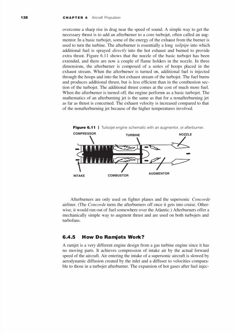
Figure 6.11 | Turbojet engine schematic with an augmentor, or afterburner.
COMPRESSORTURBINE NOZZLE
INTAKE COMBUSTORAUGMENTOR
overcome a sharp rise in drag near the speed of sound. A simple way to get thenecessary thrust is to add an afterburner to a core turbojet, often called an aug-mentor. In a basic turbojet, some of the energy of the exhaust from the burner is
used to turn the turbine. The afterburner is essentially a long tailpipe into whichadditional fuel is sprayed directly into the hot exhaust and burned to provideextra thrust. Figure 6.11 shows that the nozzle of the basic turbojet has been
extended, and there are now a couple of flame holders in the nozzle. In threedimensions, the afterburner is composed of a series of hoops placed in theexhaust stream. When the afterburner is turned on, additional fuel is injected
through the hoops and into the hot exhaust stream of the turbojet. The fuel burnsand produces additional thrust, but is less efficient than in the combustion sec-tion of the turbojet. The additional thrust comes at the cost of much more fuel.
When the afterburner is turned off, the engine performs as a basic turbojet. Themathematics of an afterburning jet is the same as that for a nonafterburning jetas far as thrust is concerned. The exhaust velocity is increased compared to that
of the nonafterburning jet because of the higher temperatures involved.
Afterburners are only used on fighter planes and the supersonic Concorde
airliner. (The Concorde turns the afterburners off once it gets into cruise. Other-
wise, it would run out of fuel somewhere over the Atlantic.) Afterburners offer amechanically simple way to augment thrust and are used on both turbojets andturbofans.
6.4.5 How Do Ramjets Work?
A ramjet is a very different engine design from a gas turbine engine since it hasno moving parts. It achieves compression of intake air by the actual forward
speed of the aircraft. Air entering the intake of a supersonic aircraft is slowed byaerodynamic diffusion created by the inlet and a diffuser to velocities compara-ble to those in a turbojet afterburner. The expansion of hot gases after fuel injec-

7/28/2019 6. Aircraft Propulsion
http://slidepdf.com/reader/full/6-aircraft-propulsion 23/30
S E C T I O N 6 . 4 Fundamental Equations Governing Jet Engines
Figure 6.12 | Ramjet engine schematic.
INLET DIFFUSER BURNER NOZZLE
Figure 6.13 | Supersonic combustion ramjet (Scramjet) engine schematic.
INLET BURNER NOZZLE
tion and combustion accelerates the exhaust air to a velocity higher than that atthe inlet, thus creating positive forward thrust [37].
The name scramjet is an acronym for supersonic combustion ramjet. The
scramjet differs from the ramjet in that combustion takes place at supersonic airvelocities through the engine. It is a simple, elegant physical design, but vastlymore complicated aerodynamically than a jet engine. Hydrogen is usually the
fuel used in the burner. Figures 6.12 and 6.13 show line drawings of a ramjetand scramjet [37].
6.4.6 How Do Ultra High Bypass Engines Work?
To improve fuel consumption, some ultra high bypass engines are on the draw-ing board. The physical layouts of components vary, but one example is the
unducted fan (UDF) engine that eliminates the need for a gearbox to drive alarge fan. The jet engine exhaust drives two counterrotating turbines that aredirectly coupled to the fan blades. The large-span fan blades are designed withvariable pitch (blade angle of attack) to accommodate various aircraft speed and
power requirements (see Figure 6.14). The advantage of a UDF engine is that 20to 30 percent reductions in fuel consumption can be achieved over subsonic tur-bofans [37].

7/28/2019 6. Aircraft Propulsion
http://slidepdf.com/reader/full/6-aircraft-propulsion 24/30
140 C H A P T E R 6 Aircraft Propulsion
Figure 6.14 | Ultra high bypass engine schematic.
COMPRESSOR
COUNTER-ROTATINGUNDUCTED FAN BLADES
COUNTER-
ROTATINGTURBINES
TURBINE
COMBUSTOR
6.5 | ROCKET ENGINES IN BRIEF
A rocket in its simplest form is a chamber enclosing a gas under pressure. Asmall opening at one end of the chamber allows the gas to escape, and in doing
so it provides a thrust that propels the rocket in the opposite direction. Think ofthe example of a balloon. Air inside a balloon is compressed by the balloon’srubber walls. The air pushes back so that the forces on each side are balancedWhen the nozzle is released, air escapes through it and the balloon is propelled
in the opposite direction. For spacecraft, the gas is produced by burning propel-lants that can be solid or liquid in form or a combination of the two.
All three of Newton’s axioms of mechanics are applicable to rocket flight.
The second and third laws have already been stated in this chapter, and the firstlaw states that
Every particle persists in a state of rest or of uniform motion in a straight line unless
acted on by a force.
When a rocket is at rest, then the forces on it are balanced. It takes an exter-nal force to unbalance the forces and make the object move. If the object is
already moving, it takes such a force to stop it, change its direction from astraight-line path, or alter its speed. In rocket flight, forces become balancedand unbalanced all the time. A rocket on the launch pad is balanced. The sur-
face of the pad pushes the rocket up while the gravitational acceleration pulls it

7/28/2019 6. Aircraft Propulsion
http://slidepdf.com/reader/full/6-aircraft-propulsion 25/30
S E C T I O N 6 . 5 Rocket Engines in Brief
toward the center of Earth. As the engines are ignited, the thrust from the rocketunbalances the forces, and the rocket travels upward. Later, when the rocketruns out of fuel, it slows down, stops at the highest point of its flight, then falls
back to Earth.Applying Newton’s second law to rocket flight highlights the pressure dif-
ferential created by the controlled explosion inside the rocket’s engines as
extreme thrust propels the rocket skyward. That pressure accelerates the gas oneway and the rocket the other. The thrust for the rocket continues as long as itsengines are firing. Because propellant is burned, the mass of the rocket changes
during flight.Rocket components include engines, payload, control system, propellant tanks,
and propellants. By far, the largest contributor to the rocket’s mass is the pro-
pellant. Newton’s second law of motion is especially useful for designing effi-cient rockets. For a rocket to climb into low Earth orbit, it must achieve a speedin excess of 28,000 km/h. A speed of over 40,250 km/h, called the escape veloc-
ity, enables a rocket to leave Earth and travel out into deep space. Attainingspaceflight speeds requires the rocket engine to achieve the greatest thrust pos-
sible in the shortest time. In other words, the engine must burn a large mass of fuel and push the resulting gas out of the engine as rapidly as possible.
Newton’s second law of motion can be restated in the following way: The
greater the mass of rocket fuel burned, and the faster the gas produced can escapethe engine, the greater the upward thrust of the rocket.
Newton’s third law of action–reaction also applies to rocket flight, as men-
tioned previously. A rocket can lift off from a launch pad only when it expels gasfrom its engine. The rocket pushes on the gas, and the gas in turn pushes on therocket. With rockets, the action is the expulsion of gas from the engine. The reac-
tion is the movement of the rocket in the opposite direction. To enable a rocketto lift off from the launch pad, the action, or thrust, from the engine must begreater than the mass of the rocket. In space, however, even tiny thrusts will
cause the rocket to change direction.An unbalanced force must be exerted for a rocket to lift off from a launch
pad or for a craft in space to change speed or direction (first law). The amount
of thrust (force) produced by a rocket engine will be determined by the mass of rocket fuel that is burned and how fast the gas escapes the rocket (second law).
The reaction, or motion, of the rocket is equal to and in the opposite direction of the action, or thrust, from the engine (third law).
Rocket Engines and Their Propellants Most rockets operate with either
solid or liquid propellants. The word propellant accounts for both the fuel andthe oxidizer. The fuel is the chemical that rockets burn, but for burning to takeplace, an oxidizer (oxygen) must be present. Jet engines draw oxygen into theirengines from the surrounding air, but rocket engines do not have this luxury;
they must carry oxygen with them into space, where there is no air.Solid rocket propellants, which are dry to the touch, contain both the fuel
and the oxidizer combined together in the chemical itself. Usually the fuel is a

7/28/2019 6. Aircraft Propulsion
http://slidepdf.com/reader/full/6-aircraft-propulsion 26/30
142 C H A P T E R 6 Aircraft Propulsion
mixture of hydrogen compounds and carbon, and the oxidizer is made up of oxy-gen compounds. Other rocket engines use liquid propellants. Liquid propellants,which are often gases that have been chilled until they condense into liquids, are
kept in separate containers: one for the fuel and the other for the oxidizer. Thenwhen the engine fires, the fuel and oxidizer are mixed together in the engine. Thisis a much more complicated engine, requiring sophisticated valves and pumps to
handle the flow of fuel. They also require special mixing chambers and propel-lant feed lines.
The fuel of a liquid-propellant rocket is usually kerosene or liquid hydrogen;
the oxidizer is usually liquid oxygen. They are combined inside a cavity calledthe combustion chamber. Here the propellants burn and build up high tempera-tures and pressures, and the expanding gas escapes through the nozzle at the
lower end. To get the maximum power from the propellants, they must be mixedas completely as possible. Small injectors (nozzles) embedded in the chamberspray and mix the propellants at the same time. Because the chamber operates
under high pressures, the propellants are forced inside by powerful, lightweighturbine pumps between the propellant tanks and combustion chambers.
With any rocket, and especially with liquid-propellant rockets, weight is animportant factor. In general, the heavier the rocket, the greater the thrust neededto get it off the ground. Due to the mass of the pumps and fuel lines, liquid
engines are much heavier than solid engines.Hybrid rockets combine elements from both types of rockets. In a hybrid
rocket, a gaseous or liquid oxidizer is stored in a tank separate from a solid fuel
grain. The major benefit of solid rockets over hybrid rockets (and liquid systems,too) is their simplicity. In hybrid systems, then, it seems that higher complexityis the price paid for better performance. However, note that the performance for
these rockets rivals that of liquid systems. Furthermore, hybrid rocket systemsrequire support for only one fluid system, including tanks, valves, regulatorsetc. In sum, although hybrid rockets are more complex than solid systems, they
offer comparable performance to liquid systems yet only half of the plumbing.This vastly reduces the overall system mass and cost, while increasing its relia-bility (fewer parts that can potentially fail). Hybrid rocket systems are also safer
to produce and store and can be more ecologically safe with proper propellantchoice; and the fuel grain, being inert, is stronger than manufactured solid pro-
pellant grains (for solid rockets), and is therefore more reliable.The mass of a rocket can make the difference between a successful flight
and just wallowing around on the launch pad. As a basic principle of rocket flight,
it can be said that for a rocket to leave the ground, the engine must produce athrust that is greater than the total mass of the vehicle. It is obvious that a rocket
with a lot of unnecessary mass is not as efficient as one that is designed for min-imum mass. For a typical rocket, the total mass of the vehicle might be distrib-uted in the following way: Of the total mass, 90 percent is propellant, 6 percentis structure (tanks, engines, fins, etc.), and 4 percent is typically payload. Pay-
loads may be satellites, astronauts, or spacecraft that will travel to the Moon orplanets. In determining the effectiveness of a rocket design, engineers speak in

7/28/2019 6. Aircraft Propulsion
http://slidepdf.com/reader/full/6-aircraft-propulsion 27/30
S E C T I O N 6 . 7 Aircraft Propulsion Simulator
Goddard.gif,
X33.jpg, Atlantis.j
Buran.jpg, X-31.m
Certification tests
and propulsion
simulator.
terms of mass fraction (MF). The mass of the propellants of the rocket dividedby the total mass of the rocket gives the mass fraction:
The mass fraction of the typical rocket given above is 0.80. From the massfraction formula one might think that an MF of 1.0 is perfect, but then the entire
rocket would be nothing more than a lump of propellants that would simplyignite into a fireball. The larger the MF number, the less payload the rocket cancarry; the smaller the MF number, the less its range becomes. An MF number of
0.80 is a good balance between payload-carrying capability and range. TheSpace Shuttle has an MF of ~0.82. The MF varies between different orbiters inthe Space Shuttle fleet and with various mission payload weights.
Rocket Demonstrations In 1926, Robert H. Goddard launched the firstliquid-fueled rocket. The 20th century has seen continuous improvement in the
design of rocket engines and their performance. Lockheed Martin has designedthe X-33 reusable launch vehicle for use in the 21st century. The rocket enginesof the Space Shuttle era include those that have propelled NASA’s Shuttle and
the Russian’s Buran reusable space vehicles into orbit. The X-1 used a rocketengine to become the first aircraft to reach supersonic flight.
6.6 | CERTIFICATION OF JET ENGINES
Returning to the topic of jet engines, this section introduces the certification test-ing that engines must undergo. Large turbofan jet engines for commercial trans-port aircraft undergo an exhaustive series of tests before they are certified, includ-
ing bird, ice, and water ingestions as well as containment of broken blades. The
bird ingestion test is a little messy, but is critical to prove that the engines willcontinue to work while flying through natural hazards. If a fan blade fails and isthrown from the hub at the incredibly high rate of rotation at which the engine isturning, passengers inside the aircraft (especially those sitting inside aligned
with the engines) want to be absolutely sure that the engine fan case will containthe broken blade and that there is no chance that the turbine blade will penetrate thefuselage. Select from the movie clips on the CD-ROM of tests conducted on the
Pratt & Whitney PW4084 engine for the Boeing 777.
6.7 | AIRCRAFT PROPULSION SIMULATORThe final section of this chapter introduces a turbofan engine simulator that brings
together the theoretical concepts introduced throughout the chapter (see theaccompanying CD-ROM). In thinking about engine performance, two importantoperational metrics emerge: What is the specific thrust of the engine and how
much fuel does the engine require? The turbofan simulation shows these two
MF ϭ mass of propellants>total mass

7/28/2019 6. Aircraft Propulsion
http://slidepdf.com/reader/full/6-aircraft-propulsion 28/30
144 C H A P T E R 6 Aircraft Propulsion
Figure 6.15 | Screen of the turbofan engine performance simulator.
metrics, specific thrust and thrust specific fuel consumption, as a function of enginecompressor pressure ratio. Parameters such as efficiencies, velocity, altitude, andengine specifications can be varied while interacting with the simulation (see
Figure 6.15). For a comprehensive propulsion reference, Aircraft Engines and
Gas Turbines by J. L. Kerrebrock [38] is highly recommended.
PROBLEMS
6.1 What is the fundamental physical principle behind propulsion? Why isthis such a necessary characteristic?
6.2 What kind of propulsion system does the Space Shuttle use, as opposed
to an airplane?
6.3 Jet engine certification. What is the first step in preparing a properly
disposed of, 8 to 10 lb bird for an FAA-regulated, large bird ingestiontest? (An engine manufacturer actually learned this the hard way).
6.4 You are on a team designing engines for a new NASA vehicle. Theprimary design requirement is that for a standard altitude of 50 km theengines produce a thrust of 150,000 N. One of your fellow design
engineers approaches you, says that she has solved the problem, and

7/28/2019 6. Aircraft Propulsion
http://slidepdf.com/reader/full/6-aircraft-propulsion 29/30
Problems
presents you with the following data: mass flow, 25 kg/s; exit area, 2 m2;
exit velocity, 4,000 m/s; and exit pressure, 2 ϫ 10 N/m2. Has she solvedthe problem? Why or why not?
6.5 The work done by the compressor is written as:
For convenience, it may also be written as
where p represents the pressure ratio and the subscript represents the
specific stage of the engine, in this case, c for compressor. Similarly, thework produced by the turbine is written
(a) C p ϭ 1,000 J/(kg и K), T 2 ϭ 300 K, and pc ϭ 30, what is T 3?
(b) Given T 5 ϭ 500 K and T 4 ϭ 2,000 K, find pt .
(c) Compute the work of the engine, W comp and W turb.
(d) The two numbers should not be equal. Why? What was not considered?
(e) Assume an ideal turbine. What is hc?
6.6 Select two of the following air/spacecraft:
(a) List a few examples of the primary requirements for engines on yourselected craft.
(b) Consider your two choices and their primary flight function. How dothey differ? What should an engineer be most concerned about whendesigning each engine?
6.7 Answer some advanced propulsion questions.
(a) Describe what you would go through if you sat on a volume of air asit traveled through an afterburning turbojet engine (aside fromvertigo and severe burns).
(b) Challenging. What limits the altitude at which a jet engine may fly?What could happen if you flew too high? (I mentioned this in lecturea couple of times—it is very bad from a performance point of view.)
(c) More challenging. What are the advantages of having multiple spoolsin a turbofan engine? (It is related to the behavior of the fan. Think of it as comparable to a big propeller . . . and how the flow changes
as it passes through the core.)
6.8 Using the Propulsion Simulator provided on the CD-ROM, answer thefollowing for an engine with a 10 m2 inlet area, M ϭ 0.8, altitude h ϭ
CPR ϭ pc and TPR ϭ pt and g ϭ 1.4
W turb ϭ 1ht cT 4 2 11 Ϫ TPR1gϪ12>g 2 ϭ cT 411 Ϫ p t 1gϪ12>g 2
W comp ϭ cT 2 1p 1gϪ12>gϪ 1 2
W comp ϭ
cT 2
hc
1CPR1gϪ
12>g Ϫ 1 2

7/28/2019 6. Aircraft Propulsion
http://slidepdf.com/reader/full/6-aircraft-propulsion 30/30
10,000 m, fan pressure ratioϭ 1.5, burner pressure ratioϭ 0.96, and aburner temperature of 1,500 K.
(a) Using the default values for engine efficiencies, for a compressor
pressure ratio (CPR) of 10, what is the specific thrust? What is thethrust specific fuel consumption?
(b) What does increasing the compressor efficiency achieve?(c) An increase in Mach number has what effect on thrust specific fuel
consumption and specific thrust?
146 C H A P T E R 6 Aircraft Propulsion
Propulsion simulator.
Related Documents
![[2ex] Electrification for Aircraft Propulsion: Modeling ...](https://static.cupdf.com/doc/110x72/623193ff94c7732f5b086c10/2ex-electrification-for-aircraft-propulsion-modeling-.jpg)