42C,D,S,V Series Fan Coil Air Conditioners Installation, Start-Up and Service Instructions CONTENTS Page SAFETY CONSIDERATIONS ...................... 1 INTRODUCTION .................................. l PHYSICAL DATA ............................... 2-4 PRE-INSTALLATION ........................... 4-43 Unpack and Inspect Units ........................ 4 Protect Units From Damage ...................... 4 Prepare Jobsite for Unit Installation .............. 4 Identify and Prepare Units ........................ 4 INSTALLATION ............................... 43-77 Step 1 -- Place Units in Position ................ 43 • 42C UNITS • 42V UNITS • 42D UNITS • 42S UNITS Step 2 -- Make Piping Connections ............. 52 • VALVE PACKAGES • 42C,D,V DRA1N CONNECTIONS • 42C,D,V WATER SUPPLY/RETURN CONNECTIONS • 42C,D,V STEAM CONNECTIONS • 42C,D,V DIRECT EXPANSION (DX) REFRIGERANT PIPING • TEST AND INSULATE Step 3 -- Make Electrical Connections .......... 65 • STANDARD WIRING PACKAGES Step 4 -- Make Duct Connections ............... 75 Step 5 -- Frame and Finish Unit ................. 75 Step 6 -- Cut out Openings for Grilles and Thermostats .................................. 75 Step 7 -- Make Final Preparations ............... 75 START-UP ..................................... 77,78 SERVICE ...................................... 78,79 Excessive Condensation on Unit ................ 78 To Clean Coil .................................... 78 Coil Air Vent (Manual or Automatic) ............. 78 Check Drain ..................................... 78 Fan Motor Bearings ............................. 78 Clean Fan Wheel ................................ 78 Clean Electric Heater ............................ 78 Clean or Replace Air Filters ..................... 78 Electrical Wiring and Controls .................. 79 Valves and Piping ............................... 79 Warranty ........................................ 79 START-UP CHECKLIST FOR 42C,D,S,V SERIES FAN COIL AIR CONDITIONERS ........ CL-1, CL-2 SAFETY CONSIDERATIONS Installation of this unit can be hazardous due to electrical com- ponents and equipment location (such as a ceiling or elevated structure). Only trained, qualified installers and service mechanics should install and service this equipment. When installing this unit, observe precautions in the literature, labels attached to the equipment, and any other safety precau- tions that apply. • Follow all safety codes. • Wear safety glasses and work gloves. Never wear bulky or loose fitting clothing when working on any mechani- cal equipment. Gloves should be worn for proper protec- tion against heat and other possible injuries. Safety glasses or goggles should always be worn when drilling, cutting, or working with chemicals such as refrigerants or lubricants. • Use care in handling and installing this unit. • Never pressurize any equipment beyond specified test pressures. Always pressure test with an inert fluid or gas such as clear water or dry nitrogen to avoid possible damage or iniury in the event of a leak or component failure during testing. Always protect adjacent flalmna- ble material when welding or soldering. Use a suitable heat-shield material to contain sparks or drops of solder. Have a fire extinguisher readily available. ELECTRIC SHOCK HAZARD. To avoid the possibility of electrical shock, open and tag all service switches before installing this equipment. INTRODUCTION Carrier fan coil units represent a prudent investment offer- ing trouble-free operation and long service with proper installa- tion, operation, and regular maintenance. Your equipment is initially protected under the manufacturer's standard warranty; however, this warranty is provided under the condition that the steps outlined in this manual for initial inspection, proper in- stallation, regular periodic maintenance, and everyday opera- tion of the equipment be followed in detail. This manual should be fully reviewed in advance before initial installation, start-up, and any maintenance. Should any questions arise, please con- tact your local sales representative or the factory BEFORE proceeding. This document contains general installation instructions for the 42C,D,S,V unit fan coils. Refer to the unit wiring diagram installed on the blower housing or specific manufacturer litera- ture for any other type of factory-mounted controls. See drawings for unit configurations, dhnensions, clearances, and pipe connections. Refer to unit wiring label for all electrical connections; follow NEC (National Electrical Code) and local codes. Manufacturer reserves the right to discontinue, or change at any time, specifications or designs without notice and without incurring obligations. Catalog No. 04-53420007-01 Printed in U.S.A. Form 42-4SI Pg 1 2-12 Replaces: 42-3SI

Welcome message from author
This document is posted to help you gain knowledge. Please leave a comment to let me know what you think about it! Share it to your friends and learn new things together.
Transcript

42C,D,S,V SeriesFan Coil Air Conditioners
Installation, Start-Up and ServiceInstructions
CONTENTS
PageSAFETY CONSIDERATIONS ...................... 1
INTRODUCTION .................................. l
PHYSICAL DATA ............................... 2-4
PRE-INSTALLATION ........................... 4-43Unpack and Inspect Units ........................ 4Protect Units From Damage ...................... 4Prepare Jobsite for Unit Installation .............. 4Identify and Prepare Units ........................ 4
INSTALLATION ............................... 43-77Step 1 -- Place Units in Position ................ 43• 42C UNITS• 42V UNITS• 42D UNITS• 42S UNITSStep 2 -- Make Piping Connections ............. 52• VALVE PACKAGES• 42C,D,V DRA1N CONNECTIONS• 42C,D,V WATER SUPPLY/RETURN
CONNECTIONS• 42C,D,V STEAM CONNECTIONS• 42C,D,V DIRECT EXPANSION (DX) REFRIGERANT
PIPING• TEST AND INSULATEStep 3 -- Make Electrical Connections .......... 65• STANDARD WIRING PACKAGESStep 4 -- Make Duct Connections ............... 75Step 5 -- Frame and Finish Unit ................. 75Step 6 -- Cut out Openings for Grilles and
Thermostats .................................. 75Step 7 -- Make Final Preparations ............... 75
START-UP ..................................... 77,78
SERVICE ...................................... 78,79Excessive Condensation on Unit ................ 78To Clean Coil .................................... 78Coil Air Vent (Manual or Automatic) ............. 78Check Drain ..................................... 78Fan Motor Bearings ............................. 78Clean Fan Wheel ................................ 78Clean Electric Heater ............................ 78Clean or Replace Air Filters ..................... 78Electrical Wiring and Controls .................. 79Valves and Piping ............................... 79Warranty ........................................ 79
START-UP CHECKLIST FOR 42C,D,S,V SERIESFAN COIL AIR CONDITIONERS ........ CL-1, CL-2
SAFETY CONSIDERATIONS
Installation of this unit can be hazardous due to electrical com-
ponents and equipment location (such as a ceiling or elevated
structure). Only trained, qualified installers and servicemechanics should install and service this equipment.
When installing this unit, observe precautions in the literature,labels attached to the equipment, and any other safety precau-tions that apply.• Follow all safety codes.• Wear safety glasses and work gloves. Never wear bulky
or loose fitting clothing when working on any mechani-cal equipment. Gloves should be worn for proper protec-tion against heat and other possible injuries. Safetyglasses or goggles should always be worn when drilling,cutting, or working with chemicals such as refrigerantsor lubricants.
• Use care in handling and installing this unit.• Never pressurize any equipment beyond specified test
pressures. Always pressure test with an inert fluid or gassuch as clear water or dry nitrogen to avoid possibledamage or iniury in the event of a leak or componentfailure during testing. Always protect adjacent flalmna-ble material when welding or soldering. Use a suitableheat-shield material to contain sparks or drops of solder.Have a fire extinguisher readily available.
ELECTRIC SHOCK HAZARD. To avoid the possibilityof electrical shock, open and tag all service switches beforeinstalling this equipment.
INTRODUCTION
Carrier fan coil units represent a prudent investment offer-ing trouble-free operation and long service with proper installa-tion, operation, and regular maintenance. Your equipment isinitially protected under the manufacturer's standard warranty;however, this warranty is provided under the condition that thesteps outlined in this manual for initial inspection, proper in-stallation, regular periodic maintenance, and everyday opera-tion of the equipment be followed in detail. This manual shouldbe fully reviewed in advance before initial installation, start-up,and any maintenance. Should any questions arise, please con-tact your local sales representative or the factory BEFOREproceeding.
This document contains general installation instructions forthe 42C,D,S,V unit fan coils. Refer to the unit wiring diagraminstalled on the blower housing or specific manufacturer litera-ture for any other type of factory-mounted controls.
See drawings for unit configurations, dhnensions, clearances,and pipe connections. Refer to unit wiring label for all electricalconnections; follow NEC (National Electrical Code) and localcodes.
Manufacturer reserves the right to discontinue, or change at any time, specifications or designs without notice and without incurring obligations.
Catalog No. 04-53420007-01 Printed in U.S.A. Form 42-4SI Pg 1 2-12 Replaces: 42-3SI
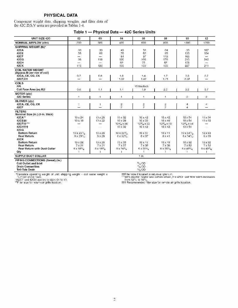
PHYSICAL DATA
Component weight data, shipping weights, and filter data ofthe 42C,D,S,V units are provided in Tables 1-4.
Table 1 -- Physical Data -- 42C Series Units
UNIT SIZE 42C
NOMINAL AIRFLOW (cfm)
SHIPPING WEIGHT (Ib)*42CA42CE42CF42CG42CH42CK
COIL WATER WEIGHT(Approx Ib per row of coil)
42CA, CE, CG, CK42CF, CH
COILSFPI
Coil Face Area (sq ft)l-
MOTOR (qty)42C Series
BLOWER (qty)42CA, CE, CG, CK42CF
FILTERSNominal Size (in.) (1-in. thick)
42CA**
42CEM-42CFM-***42CHM-I-42CG
Bottom ReturnRear Return
42CKBottom ReturnRear ReturnRear Return with Duct Collar
Qty
SUPPLY DUCT COLLAR
02 03 04 06 08 10 12
200 300 400 600 800 1000 1200
36
55
98
115
39
60
118
120
497084
12662135
598297
16873
150
6495
11017682155
95 107135 154163215 245128227 241
0.7 i 0.8I 1.011.411.712.312.7-- -- 1.02 1.42 1.71 2.32 --
10 fins/inch
0.8 I 1.1 I 1.4 I 1.9 I 2.3 I 3.2 I 3.7
1 I t I t I t I 1 I 2 I 2
1 I t I 2 2 2 4 4- I I I I -10 x 2410 x 18
10 x 231_
8 x 231_
10 x 2810 x 22
10 x 288 x 28
10x287x21
6 x 183/41
10x 28
7x21
6 x 183/41
10 x 32
10x28
123/4 x 2810 x 32
10 x 321/2
8 x 321/2
10 x 337x27
6 x 243/41
10 x 42
10 x 33
123/4 x 3310 x 42
10x 378x37
10x457x38
6 x 353/41
1-in.
10 x 42
10 x 40
123/4 x 4010 x 42
10x418x41
10 x 45
7 x 38
6 x 35341
5/80D7/80D
5/80D
1-1-Filter size if located in return-air plenum.
PIPING CONNECTIONS (Sweat) (in.)Coil Outlet and InletDrain ConnectionTell-Tale Drain
*Calculate operating weight of unit: shipping weight + coil water weight xnumber of coil rows.
1-42CF and 42CH applies to sizes 04 to 10.**Filter size for return-air grille location.
10x54 10x6410x54 10x62
123/4 x 5410x 54
10 x 541/2 10x638 x 541/2 8 x 63
10x62 10x627x52 7x52
6 x 493/4 6 x 493/41 1
***With electric heater and bottom return, the 42CF unit filter width increasesfrom 123/4 to 163/4 .
ttt Recommended filter size for remote air grille location.

UNIT SIZE 42V
NOMINAL AIRFLOW (cfm)
SHIPPING WEIGHT (Ib)*42VA42VB42VC42VE42VF42VG
COIL WATER WEIGHT(Approx Ib per row of coil)
42VA, VB, VC'I-, VF42VE42VG
COILSFPI
Coil Face Area (sq ft)
MOTOR (qty)42VA, VB, VF42VC, VE42VG
BLOWER (qty)42VA, VB, VF42VC, VE42VG
FILTERS
Nominal Size (in.) (1-in. thick)42VA, VB, VF42VC, VE42VG
Qty
SUPPLY DUCT COLLAR
PIPING CONNECTIONS (Sweat) (in.)Coil Outlet and InletDrain Connection
Table 2 -- Physical Data -- 42V Series Units
01 02 I 03 04 06 I 08
150 200 I 300 400 600 I 800
m
m
m
m
m
40
6589507292
8O9560
1009874
9011672
108122
112134110154141
115137
144
I 101000
140169
178
UNIT SIZE 42D
NOMINAL AIRFLOW (cfm)
SHIPPING WEIGHT (Ib)*42DA42DC42DD42DE42DF
COIL WATER WEIGHT(Approx Ib per row of coil)
COILSFPI
Coil Face Area (sq ft)
MOTOR (qty)
BLOWER (qty)
FILTERSNominal Size (in.) (1-in. thick)
42DA42DC42DD
(Front Return)(Bottom Return)
42DE42DF
Qty
SUPPLY DUCT COLLAR
PIPING CONNECTIONS(Sweat - 4-Row)
Inlet (in. OD)Outlet (in. OD)
12
1200
170192
205
0.710.810 1.411.712.327-- 0.9 1.2 1.6 2.3 -- -- --0.4 -- 1.0 .....
12 fins/inch
0.8 I 0.8 I 1.1 I 1.4 I 1.9 I 2.3 I 3.2 I 3.7
111 1-- 1 1 1 2 -- -- --1 -- 2 .....
111 i i 4 4-- 2 2 2 4 -- -- --1 -- 2 .....
---- 73/4 X 213/4 173/4 X263/47X 213/4 7 X 263/473/4 X313/47X 343/473/4X413/4173/4X433/4173/4X573/47X 483/4 -- -- 73/4 X653/4--10 X 141/2 -- 10 X 28 .....
1 1 1 1 1 1 1 1
1-in.
5/80D3/4 MPT
*Calculate operating weight of unit: shipping weight + coil water weight x 1-Available in sizes 02-06.number of coil rows.
Table 3 -- Physical Data -- 42D Series Units
06 08 10 12 I 14 I 16 18 20
600 800 1000 1200 I 1400 I 1600 1800 2000
64 79 93 110 119 129 137 15594 107 150 169 174 178 195 220
150 163 176 195 220 235 240 247135 155 165 184 199 215 232 243157 167 177 199 215 229 249 258
1.3 1.6 1.9 2.3 2.7 3.0 3.4 3.7
10 fins/inch
1.6 2.1 2.5 3.0 I 3.5 I 4.1 4.6 5.0
1 1 1 2 I 2 I 2 2 21 1 1 2 2 2 2 2
14x21 I 14x 26 I 14x30 I 14x 35
123& x 35123& x 3414 x 283&
14 x 28
NA14 x40
123/4 x 40123/4 x 3914 x 333/4
14 x 34
14X45 I 14XS0 I 14X54
123/4 x 45123/4 x 4414 x 383/4
14 x 38
123/4 x 26123/4 x 2514 x 193/4
14 x20
123& x 21
123& x 21
14 x143&14 x 14
123/4 X 30123/4 X 2914 X 233/4
14 X24
123& X 50123& X 4914 X 433&
14 X 44
1-in.
5/8 I 7/8 I 11/85/8 7/8 11/8
*Calculate Operating Weight of unit: Shipping Weight + Coil Water Weight x Number of Coil Rows.
123/4 x 54123/4 x 5314 x 473/4
14 x48

Table 4 -- Physical Data- 42S Series Units
o...s.zE42so3 o4I o6I o8 ,o ,2I ,4 ,6 2oNOMINAL AIRFLOW (cfm) 300 400 600 800 1000 1200 1400 1600 2000SHIPPING WEIGHT (Ib)*42SGA,SGM,SU 180 225 240 260 280 305 -- -- --42SH 202 247 262 286 311 336 -- -- --42SJ 360 450 480 520 560 610 -- -- --42SGS 162 203 216 234 252 275 -- -- --42SM ...... 390 390 390
COIL WATERWEIGHT(Approx Ib per row of coil) 1.79 2.63 3.45 4.09 4.09 4.39COILSFPI 14 fins/inch
BLOWER (qty)42SGA,SH,SU,SGM,SGS,SM 1 1 1 1 1 1 1 1 1
FILTERS
,om,na,Size,,n.,,-in.t,,c,, I I I IQty 11-
PIPING CONNECTIONSInlet (in. OD) 1/2, unless larger size valve package is selected
*Calculate Operating Weight of Unit: Shipping Weight + Coil Water Weight x Number of Coil Rows.t42SJ units require two filters.
PRE-INSTALLATION
Unpack and Inspect Units--All units are carefullyinspected at the factory throughout the manufacturing processunder a strict detailed quality assurance progrmn, and, wherepossible, ALL maior components and sub-assemblies are care-fully tested for proper operation and verified for full compli-ance with factory standards. Operational testing of some cus-tomer furnished components such as electronic control valvesand digital controllers may be a possible exception.
Each unit is carefully packaged for shipment to avoid dmn-age during normal transit and handling. Equipment should al-ways be stored in a dry place, and in the proper orientation asmarked on the carton. All shipments are made F.O.B. factoryand are the responsibility of the receiving party to inspect theequipment upon arrival. Any obvious damage to the cartonand/or its contents should be recorded on the bill of lading anda claim should be filed with the transportation company, andCarrier should be advised. After determining the condition ofthe carton exterior, carefully remove each unit from the cartonand inspect for hidden dmnage. At this trine, check to makesure that "furnished only" items such as thermostats, grilles etc.are accounted for whether packaged separately or shipped at alater date. Any hidden damage should be recorded and imme-diately reported to the transportation company, a claim shouldbe filed with the transportation company, and Carrier should benotified. In the event a claim for shipping damage is filed, theunit, shipping carton, and all packing must be retained forphysical inspection by the transportation company. All equip-ment should be stored in the factory shipping carton with inter-nal packing in place until installation.
At the time of receipt, the equipment type and arrangementshould be verified against the order documents. Should anydiscrepancy be found, the local sales representative should benotified finrnediately so that proper action may be taken.Should any questions arise concerning warranty repairs, thefactory must be notified BEFORE any corrective action is tak-en. Where local repairs or alterations can be accomplished, thefactory must be fully informed of the extent and expected costof those repairs before work is begun. Where factory opera-tions are required, the factory must be contacted for authoriza-tion to return equipment and a Return Authorization Numberwill be issued. Unauthorized return shipments of equipmentand shipments not marked with an authorization number willbe refused. In addition, any claims for unauthorized expenseswill not be accepted by the manufacturer.
Protect Units from Damage -- The equipment mustalways be properly supported. Temporary supports used duringinstallation or service must be adequate to hold the equipmentsecurely. Equipment should always be stored in the proper ori-entation as marked on the carton. To maintain warranty, protectunits against hostile enviromnent (such as rain, snow, or ex-treme temperatures), theft, vandalism, and debris on jobsite.Equipment covered in this manual is not suitable for outdoorinstallations. Do not allow foreign material to fall into drainpan. Prevent dust and debris from being deposited on motorand fan wheels. Failure to do so may have serious adverse ef-fects on unit operation, and in the case of the motor and blowerassembly, may result in innnediate or premature failure. Manu-facturer's warranty is void if foreign material is allowed to bedeposited on the motor or blower wheels of any unit. Someunits and/or job conditions may require some form of tempo-rary covering during construction.
Prepare Jobsite for Unit Installation -- To savetime and to reduce the possibility of costly errors, set up a com-plete sample installation in a typical room at jobsite. Check allcritical dimensions such as pipe, wire, and duct connectionrequirements. Refer to job drawings and product dimensiondrawings as required (see Fig. 1-39). Instruct all trades in theirpart of the installation.
Identify and Prepare Units -- Be sure power require-ments match available power source. Refer to unit nameplateand wiring diagram.
1. Check all tags on unit to determine if shipping screws areto be removed. Remove screws as directed.
2. Rotate the fan wheel by hand to ensure that the fan isunrestricted and can rotate freely. Check for shippingdamage and fan obstructions.
2
]1 ........... "_t E-_-_-;
r--
_4/2_8"
%1/8(2Q1
2-t/4
r .... ]L .... d
-+i..............................................I
JA
TOPVlEW
FRONTVIEW
# ,.
i I -
4._
_5
17-1/2
C213) 4
RIGHTSIDEVIEW
"9
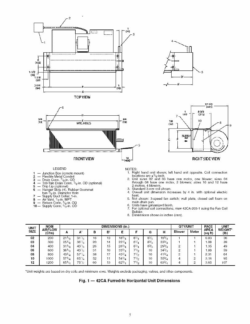
LEGEND
"1 -- Junction Box (remote mount)2 -- Flexible Metal Conduit3 -- Drain Conn, 7/8-in. OD4 -- Tell-Tale Drain Conn, 5/8-in. OD (optional)5 -- Drip Lip (optional)6 -- Hanger Slots (4), Rubber Grommet
has 3/8-in. Diameter Hole7 -- Supply Duct Collar, 1-in.8 -- Air Vent, 1/8-in. MPT9 -- Return Conn, 5/8-in. OD10-- Supply Conn, 5/8-in. OD
NOTES:1. Right hand unit shown; left hand unit opposite. Coil connection
locations are _+5/8-inch.2. Unit sizes 02 and 03 have one motor, one blower; sizes 04
through 08 have one motor, 2 blowers; sizes 10 and 12 have2 motors, 4 blowers.
3. Standard 3-row coil shown.4. Overall unit dimension increases by 4 in. with optional electric
heat.5. Not shown: 3-speed fan switch; wall plate, closed cell foam on
main drain pan.6. Units have galvanized finish.7. For optional coil connections, view 42CA-203-1 using the Fan Coil
Builder.8. Dimensions shown in inches (mm).
UNITSIZE
02
03O406
081012
NOM DIMENSIONS (in.)AIRFLOW
(Cfm) A A' B D' E F G H
200 211/4 311/4 16 13 181/4 61/4 83/4 193/4300 251/4 361/4 20 14 221/4 61/4 83/4 233/4400 311/4 431/4 26 15 281/4 61/4 83/4 293/4600 361/4 431/4 31 10 331/4 71/2 10 343/4800 431/4 571/4 38 17 401/4 71/2 10 413/4
1000 571/4 651/4 52 11 541/4 71/2 10 553/4
1200 651/4 751/4 60 13 621/4 71/2 10 633/4
QTY/UNIT
Blower Motor
1122244
1111122
*Unit weights are based on dry coils and minimum rows. Weights exclude packaging, valves, and other components.
Fig. 1 -- 420A Furred-In Horizontal Unit Dimensions
FACE UNITAREA WEIGHT*(sq ft) (Ib)
0.83 361.08 391.35 491.88 592.31 643.16 953.65 107

,1 5.,-r---i r ....
'---_ L....J 3
4
)
TOP VMEW
5
1
8
STD 7 "-'_'\,_, \L2_
3
suNt
1
2%1/2
_2-3J_
_ (3t4) _9
r
/ I
1 Ii i
....... 1 _
-lO
RIGHTsl DE VIEW
LEGEND
1 -- Junction Box (remote mount)2 -- Flexible Metal Conduit3 -- Strip Heater High Limit4 -- Electric Strip Heater Element5 -- Tell-Tale Drain Conn, 5/8-in. OD (optional)6 -- Drain Conn, 7/8-in. OD7 -- Drip Lip (optional)8 -- Supply Duct Collar, 1-in.9 -- Air Vent, 1/8-in. MPT10-- Return Conn, 5/8-in. OD11 -- Supply Conn, 5/8-in. OD12-- Hanger Slots (4), Rubber Grommet
has 3/8-in. Diameter Hole
NOTES:1. Right hand unit shown; left hand unit opposite. Coil connection
locations are _+5/8-inch.2. Unit sizes 02 and 03 have one motor, one blower; sizes 04
through 08 have one motor, 2 blowers; sizes 10 and 12 have2 motors, 4 blowers.
3. Standard 3-row coil shown.4. Overall unit dimension increases by 4 in. with optional electric
heat.5. Not shown: 3-speed fan switch; wall plate, closed cell foam on
main drain pan.6. Units have galvanized finish.7. For optional coil connections, view 42CA-203-1 using the Fan Coil
Builder.8. Dimensions shown in inches (mm).
UNITSIZE
02030406081012
NOM DIMENSIONS (in.)AIRFLOW
(Cfm) A A' B D' E F G H
200 211_ 311_ 16 13 181_ 61_ 83_ 193_
300 251_ 361_ 20 14 221_ 61_ 83_ 233_
400 311_ 431_ 26 15 281_ 61_ 83_ 293_
600 3614 4314 31 10 3314 71_ 10 3434
800 4314 5714 38 17 4014 71_ 10 4134
1000 5714 6514 52 11 5414 71_ 10 5534
1200 6514 7514 60 13 6214 71_ 10 6334
QTY/UNIT
Blower Motor
1122244
1111122
*Unit weights are based on dry coils and minimum rows. Weights exclude packaging, valves, and other components.
FACE UNITAREA WEIGHT*(sq ft) (Ib)
0.83 381.08 411.35 511.88 612.31 663.16 973.65 109
Fig. 2 -- 420A Furred-In Horizontal Unit with Electric Heat Dimensions
2 _ |NSU_TEB
I \ 71-c3o
I Iq ,_i P, ',t V_)ImNL_ 12"t I._ _1 I | /
lit .....,i iHJI r__-, ............ _ ............. q,_ &I li :------ ........-----z: 4
-rI' Z,,oNI
2-1Y4__ I . 36_ " I- b -(76)
TOPVIEW
PLENUM
5
6 , /-7j,
i '__' J _ _ _ _ 8
- oJ ((
I:_TER _AL
OPTIONALRFARRETURN
II_ Fi_I 5
FRONTVIEW
3/4
14/" 13
"N. 10
"-"'--7
"_) T
_- 12
/ ,' ; 1!
..... ____ r__t •
' IP_-": .......
_F_N1"(2_1FILT_ AiR _L_R
_MOV#,L
RIGHT SIDE _EW
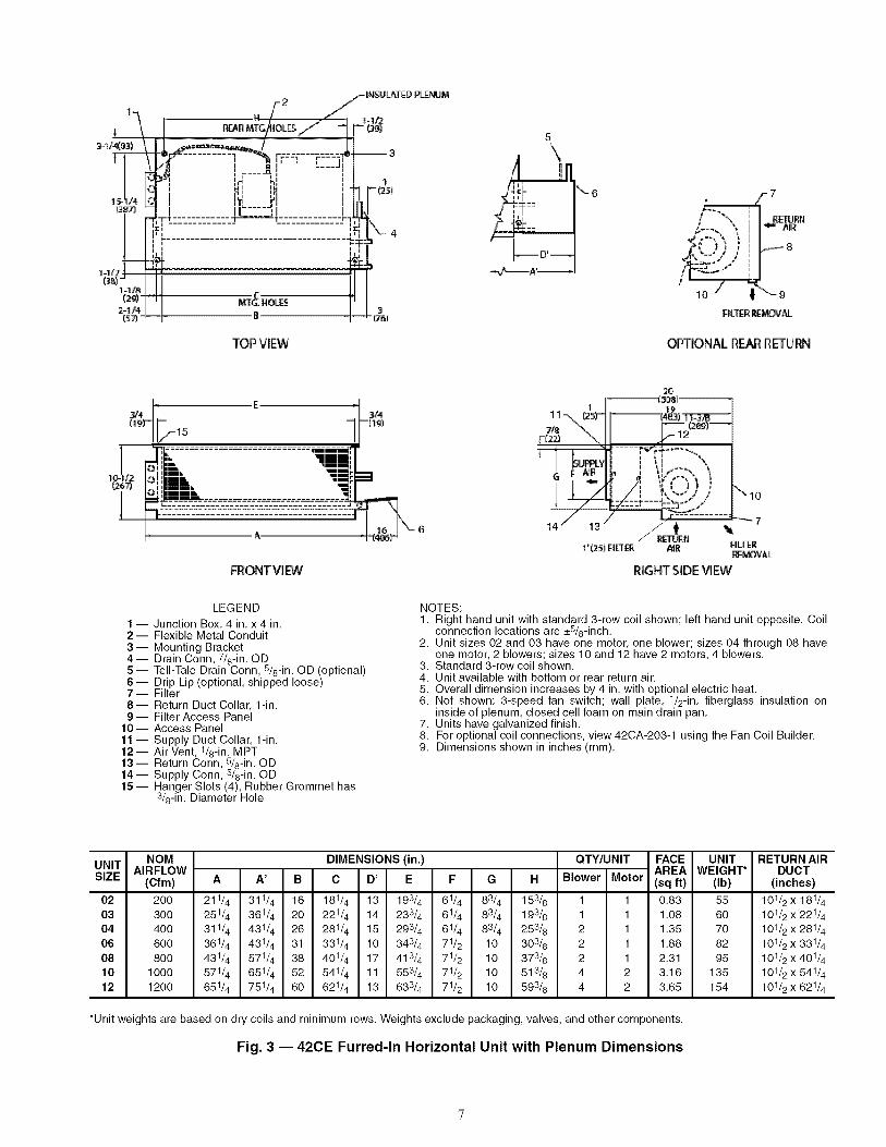
LEGEND
"1-- Junction Box, 4 in. x 4 in.2- Flexible Metal Conduit3-- Mounting Bracket4-- Drain Conn, 7/8-in. OD5 -- Tell-Tale Drain Conn, S/g-in. OD (optional)6 -- Drip Lip (optional, shipped loose)7- Filter8- Return Duct Collar, 1-in.9 -- Filter Access Panel
"10-- Access Panel"1"1-- Supply Duct Collar, 1-in."12-- Air Vent, 1/8-in. MPT"13-- Return Conn, 5/8-in. OD"14-- Supply Conn, s/8-in. OD"15-- Hanger Slots (4), Rubber Grommet has
3/8-in. Diameter Hole
NOTES:1, Right hand unit with standard 3-row coil shown; left hand unit opposite, Coil
connection locations are _+5/8-inch,2, Unit sizes 02 and 03 have one motor, one blower; sizes 04 through 08 have
one motor, 2 blowers; sizes 10 and 12 have 2 motors, 4 blowers,3, Standard 3-row coil shown,4, Unit available with bottom or rear return air,5, Overall dimension increases by 4 in, with optional electric heat,6, Not shown: 3-speed fan switch; wall plate, 1/2-in, fiberglass insulation on
inside of plenum, closed cell foam on main drain pan,7, Units have galvanized finish,8, For optional coil connections, view 42CA-203-1 using the Fan Coil Builder,9, Dimensions shown in inches (mm),
UNITSIZE
02030406081012
NOM DIMENSIONS (in.) QTY/UNIT FACE
AIRFLOW (sq ft)(Cfm) A A' B C D' E F G H Blower Motor AREA
200 211/4 311/4 16 181/4 13 193/4 61/4 83/4 153/8 1 1 0,83300 251/4 361/4 20 221/4 14 233/4 61/4 83/4 193/8 1 1 1,08400 311/4 431/4 26 281/4 15 293/4 61/4 83/4 253/8 2 1 1,35600 361/4 431/4 31 331/4 10 343/4 71/2 10 303/8 2 1 1,88800 431/4 571/4 38 401/4 17 413/4 71/2 10 373/8 2 1 2,31
1000 571/4 651/4 52 541/4 11 553/4 71/2 10 513/8 4 2 3,161200 651/4 751/4 60 621/4 13 633/4 71/2 10 593/8 4 2 3,65
*Unit weights are based on dry coils and minimum rows. Weights exclude packaging, valves, and other components.
Fig. 3 -- 420E Furred-In Horizontal Unit with Plenum Dimensions
UNIT RETURN AIRWEIGHT* DUCT
(Ib) (inches)
55 101/2 x 181/4
60 101/2 X 221/4
70 101/2 X 281/4
82 101/2 X 331/4
95 101/2 X 401/4
135 101/2 X 541/4
154 101/2 X 621/4

19-tf4(4B91
TOPVlBH
FRO_ VIEW
!, ill
: - 8
/-9
li_ Am
_{'-') t _ III /-10
12"-/ ;_'_- 11
OPTIONALR_R RETURN
16
RIGHT SIDE VIEW
LEGEND
"1-- Junction Box, 4 in. x 4 in.2- Flexible Metal Conduit3-- Mounting Bracket4 -- Electric Strip Heater Element5 -- Drain Conn, 7/8-in. OD6 -- Strip Heater High Limit7- Tell-Tale Drain Conn, s/8-in. OD (optional)8-- Drip Lip (optional, shipped loose)9- Filter
10-- Return Duct Collar, 1-in.11 -- Filter Access Panel12-- Access Panel13 -- Supply Duct Collar, 1-in.14 -- Air Vent, 1/8-in. MPT15 -- Return Conn, s/8-in. OD16 -- Supply Conn, s/8-in. OD"17-- Hanger Slots (4), Rubber Grommet has
3/8-in. Diameter Hole
NOTES:1. Right hand unit with standard 3-row coil shown; left hand unit opposite. Coil
connection locations are _+8/8-inch.2. Unit sizes 02 and 03 have one motor, one blower; sizes 04 through 08 have
one motor, 2 blowers; sizes 10 and 12 have 2 motors, 4 blowers.3. Standard 3-row coil shown.4. Unit available with bottom or rear return air.5. Overall dimension increases by 4 in. with optional electric heat.6. Not shown: 3-speed fan switch; wall plate, 1/2-in. fiberglass insulation on
inside of plenum, closed cell foam on main drain pan.7. Units have galvanized finish.8. For optional coil connections, view 42CA-203-1 using the Fan Coil Builder.9. Dimensions shown in inches (mm).
UNITSIZE
02030406081012
NOM DIMENSIONS (in.) QTY/UNIT FACE UNIT RETURN AIRAIRFLOW AREA WEIGHT*
(Cfm) A A' B C D' E F G H Blower Motor (sq ft) (Ib) DUCT
200 211/4 311/4 16 181/4 13 193/4 61/4 83/4 153/8 1 1 0,83 57 101/2 x 181/4
300 251/4 361/4 20 221/4 14 233/4 61/4 83/4 193/8 1 1 1,08 62 101/2 x 221/4
400 311/4 431/4 26 281/4 15 293/4 61/4 83/4 253/8 2 1 1,35 72 101/2 x 281/4
600 361/4 431/4 31 331/4 10 343/4 71/2 10 303/8 2 1 1,88 84 101/2 x 331/4
800 431/4 571/4 38 401/4 17 413/4 71/2 10 373/8 2 1 2,31 97 101/2 x 401/4
1000 571/4 651/4 52 541/4 11 553/4 71/2 10 513/8 4 2 3,16 137 101/2 x 541/4
1200 651/4 751/4 60 621/4 13 633/4 71/2 10 593/8 4 2 3,65 156 101/2 x 621/4
*Unit weights are based on dry coils and minimum rows. Weights exclude packaging, valves, and other components.
Fig. 4 -- 420E Furred-In Horizontal Unit with Plenum and Electric Heat Dimensions

LEGEND
"1-- Junction Box, Installed with Plenum2- Flexible Metal Conduit3-- Insulated Plenum4-- Mounting Bracket5 -- Drain Conn, 7/8-in. OD6- Tell-Tale Drain Conn, 5/8-in. OD (optional)7 -- Drip Lip (optional, shipped loose)8-- Filter9 -- Return Duct Collar, 1-in.
"10-- Access Panel11 -- Supply Duct Collar, 1-in.12 -- Supply Conn, 5/8-in. OD13 Air Vent, 1/8-in. MPT14 -- Return Conn, 5/8-in. OD15 -- Hanger Slots (4), Rubber Grommet has
3/8-in. Diameter Hole
6
-7ii
_D _
_A'_
£8
Ill Am
/ ,,"==|
10 _ _F_ £RFILT[R CUP_OVAL
OPTIO_L R_R RETURN
7ia 11
1i "X,_ 12/ X
14 / 8 _
214/2 _I--- -I
I
i '_N[_N FILT_RR_OVAL
RIGHTSIDEVIEW
NOTES:1. Right hand unit shown; left hand unit opposite. Coil connection
locations are _+5/8-inch.2. Unit sizes 04 thru 08 have one motor, 2 blowers; size 10 has
2 motors, 4 blowers.3. Refer to above figure for configuration of filter and track if
installed in optional plenum.4. Overall dimension increases by 4 in. with optional electric heat.5. Not shown: 3-speed fan switch; wall plate, 1/2-in. fiberglass
insulation on inside of plenum (when installed), closed cellinsulation on main drain pan.
6. Units have galvanized finish.7. For optional coil connections, view 42CA-203-1 using the Fan
Coil Builder.8. Dimensions shown in inches (mm).
UNITSIZE
04060810
NOMAIRFLOW
(Cfm) A A' B
400 311& 431_ 26600 361_ 431_ 34800 431_ 571_ 38
1000 571_ 651_ 52
DIMENSIONS (in.)
C D' E
QTY/UNIT
Blower Motor
281/4 15 293/4 61/4 83/4 301/4331/4 10 343/4 71/2 10 351/4401/4 17 413/4 71/2 10 421/4541/4 11 553/4 71/2 10 561/4
2224
1112
*Unit weights are based on dry coils and minimum rows. Weights exclude packaging, valves, and other components.
Fig. 5 -- 420F Furred-In High-Static Horizontal Unit with Plenum Dimensions
FACEAREA(sq ft)
1.351.882.313.16
UNITWEIGHT*
(Ib)
84
97
110
163

1 3 2
3 1
IJi
I
TOP_EW
8 9
"- -L I°.
O_ONAL REAR R_RN!
--11-,,,1
_[CTR_J_,L _,qqOC_SIN _P & BOOM 0_:
CONT_O_ 90X
LEGEND
"1-- Junction Box, Installed with Plenum2- Plenum3- Flexible Metal Conduit4-- Mounting Bracket
-- Electric Strip Heater ElementDrain Conn, 7/8-in. OD
-- Drip Lip (optional, shipped loose)Tell-Tale Drain Conn, 5/8-in. OD (optional)9- Filter
10-- Return Duct Collar, 1-in.11 -- Air Vent, 1/8-in. MPT12-- Access Panel13 -- Return Conn, 5/8-in. OD14 -- Supply Conn, 5/8-in. OD15 -- Supply Duct Collar, 1-in.16 -- Hanger Slots (4), Rubber Grommet has
3/8-in. Diameter Hole
NOTES:1.
2.
3.
4.5.
6.
7.
8.
Right hand unit shown; left hand unit opposite. Coil connectionlocations are _+5/8-inch.Unit sizes 04 thru 08 have one motor, 2 blowers; size 10 has2 motors, 4 blowers.Refer to above figure for configuration of filter and track ifinstalled in optional plenum.Overall dimension increases by 4 in. with optional electric heat.Not shown: 3-speed fan switch; wall plate, 1/2-in. fiberglassinsulation on inside of plenum (when installed), closed cellinsulation on main drain pan.Units have galvanized finish.For optional coil connections, view 42CA-203-1 using the FanCoil Builder.Dimensions shown in inches (mm).
UNITSIZE
04060810
NOMAIRFLOW
(Cfm)
4OO6OO8OO
1000
A _
DIMENSIONS (in.)
C D' E G H
311/4 431/4 26 281/4 15 293/4 61/4 83/4 301/4
361/4 431/4 34 331/4 10 343/4 71/2 10 351/4
431/4 571/4 38 401/4 17 413/4 71/2 10 421/4
571/4 651/4 52 541/4 11 553/4 71/2 10 561/4
QTY/UNIT
Blower Motor
2224
1112
FACEAREA(sq ft)
1.351.882.313.16
*Unit weights are based on dry coils and minimum rows. Weights exclude packaging, valves, and other components.
Fig. 6 -- 42CF Furred-In Horizontal Unit with Plenum and Electric Heat Dimensions
UNITWEIGHT*
(Ib)
8497
110163
10
(8#)
14571
TOP VIFW
C
L Jl
I._III._II
I._II
/15J
ii,, II
" IIII
II II
IL JL I
C
FROI'7 VIEW
2
6
8
PARTIALREARVEW_fP_ BO_N_051
RIGHT SIDE VIEW
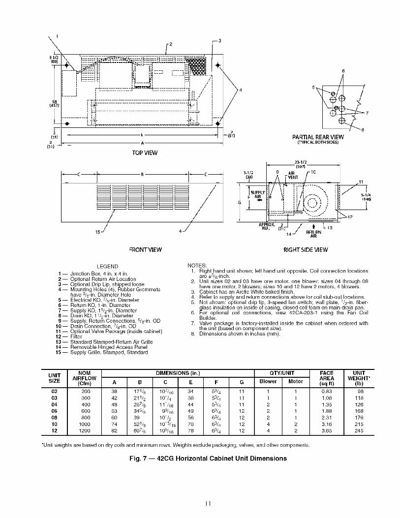
LEGEND
1 -- Junction Box, 4 in, x 4 in,2 -- Optional Return Air Location3 -- Optional Drip Lip, shipped loose4 -- Mounting Holes (4), Rubber Grommets
have 3/8-in, Diameter Hole5- Electrical KO, 7/8-in, Diameter6- Return KO, 1-in, Diameter7 -- Supply KO, 11/2-in, Diameter8-- Drain KO, 11/2-in, Diameter9-- Supply, Return Connections, 5/8-in, OD
10-- Drain Connection, 7/8-in, OD11 -- Optional Valve Package (inside cabinet)12-- Filter13 -- Standard Stamped-Return Air Grille14 -- Removable Hinged Access Panel15 -- Supply Grille, Stamped, Standard
NOTES:1, Right hand unit shown; left hand unit opposite, Coil connection locations
are _+5/8-inch,2, Unit sizes 02 and 03 have one motor, one blower; sizes 04 through 08
have one motor, 2 blowers; sizes 10 and 12 have 2 motors, 4 blowers,3, Cabinet has an Arctic White baked finish,4, Refer to supply and return connections above for coil stub-out locations,5, Not shown: optional drip lip, 3-speed fan switch; wall plate, 1/2-in, fiber-
glass insulation on inside of casing, closed cell foam on main drain pan,6, For optional coil connections, view 42CA-203-1 using the Fan Coil
Builder,7, Valve package is factory-installed inside the cabinet when ordered with
the unit (based on component size),8, Dimensions shown in inches (mm),
UNITSIZE
02030406081012
NOM DIMENSIONS (in.)AIRFLOW
(Cfm) A B C E F G
200 38 171/8 107/16 34 53/4 11
300 42 211/2 101/4 38 53/4 11400 48 257/8 111/16 44 53/4 11600 53 348/8 93/16 49 63/4 12
800 60 39 101/2 56 63/4 121000 74 521/8 1015/16 70 63/4 121200 82 607/8 109/16 78 63/4 12
QTY/UNIT
Blower Motor
1 1
1 12 12 1
2 14 24 2
FACEAREA(sq ft)
0.83
1.081.351.88
2.313.163.65
UNITWEIGHT*
(Ib)
98
118126168
176215245
*Unit weights are based on dry coils and minimum rows. Weights exclude packaging, valves, and other components.
Fig. 7 -- 420G Horizontal Cabinet Unit Dimensions
1!

2
L_
r.... ;
TOP VIEW
_,r ,.
I,--11, II
//
16-/
FRONTVIEW
LEGEND
1 -- Junction Box, 4 in. x 4 in.2 -- Optional Stamped Rear Return Grille3 -- Optional Drip Lip, shipped loose4 -- Electric Strip Heater Element5 -- Mounting Holes (4), Rubber Grommets
have 3/8-in. Diameter Hole6 -- Electrical KO, 7/8-in. Diameter7- Return KO, 1-in. Diameter8 -- Supply KO, 11/2-in. Diameter9- Drain KO, 11/2-in. Diameter
10-- Drain Connection, 7/8-in. OD11 -- Optional Valve Package (inside cabinet)12-- Filter13 -- Standard Stamped-Return Air Grille14 -- Removable Hinged Access Panel15 -- Supply, Return Connections, 5/8-in. OD16 -- Supply Grille, Stamped, Standard
NOTES:1.
4
I I 2
C
7
PAR_ALR_R VIM_¥gir,,_AtBOT'_$_r_)
11
_12
RIGHTSIDE'_,a_
Right hand unit shown; left hand unit opposite. Coil connectionlocations are _+8/8-inch.
2. Unit sizes 02 and 03 have one motor, one blower; sizes 04through 08 have one motor, 2 blowers; sizes 10 and 12 have2 motors, 4 blowers.
3. Cabinet has an Arctic White baked finish.4. Refer to supply and return connections above for coil stub-out
locations.5. Not shown: optional drip lip, 3-speed fan switch; wall plate,
1/2-in. fiberglass insulation on inside of casing, closed cell foamon main drain pan.
6. For optional coil connections, view 42CA-203-1 using the FanCoil Builder.
7. Valve package is factory-installed inside the cabinet whenordered with the unit (based on component size).
8. Dimensions shown in inches (mm).
UNITSIZE
02030406081012
NOM DIMENSIONS (in.) QTY/UNITAIRFLOW
(Cfm) A B C E F G Blower Motor
200 38 171/8 107/16 34 53/4 11 1 1
300 42 211/2 101/4 38 53/4 11 1 1400 48 257/8 111/16 44 53/4 11 2 1600 53 345/8 93/16 49 63/4 12 2 1
800 60 39 101/2 56 63/4 12 2 11000 74 521/8 1018/16 70 63/4 12 4 21200 82 607/8 109/16 78 63/4 12 4 2
*Unit weights are based on dry coils and minimum rows. Weights exclude packaging, valves, and other components.
Fig. 8 -- 420G Horizontal Cabinet with Electric Heat Dimensions
FACE UNITAREA WEIGHT*(sq ft) (Ib)
0.83 981.08 1181.35 1261.88 1682.31 1763.16 2153.65 245
12

F FLEXIBLE METAL
CONDUIT
_ .................................. , r_ z
JUNCTION BO_XX _"J
(REMOTE )UNT)
1-1/2 Y(38)-- ,I E
1-1/8 MTG.HOLES(29)_
2-1/4 4 B
(57) _ ,J ^
r .... .-iI !i. .... J
ml I1
'............... " _,,,]-]I,'_I
D=
1(25)
7/8"(22) O.D.CONDENSATE
DRAIN
3_(76)
TOP VIEW
OPTIONAL
5/8"(16) O.D.TELL-TALE
DRAINCONNECTION,
AVAILABLE
ONSTANDARD-"_ flAND EXTENDED
DRAINPANS/]'_
i-4i-
OPTIONAL EXTENDED
k"m_ u _ I DRAIN PAN (SEE NOTE 2)
/
3/4
RESILIENTMOUNTING GROMMETW/3/8"(10) DIA. HOLES (TYP.OF 4)
H
EL3/4
_(19) CHILLED/HOTWATER
RETURNCONNECTIONS
A
FRONT VIEW
"_ k"L OPTIONALI I \ DRIPLIP
"/ I --SHIPPED1_-16--_ LOOSE
(406) (NOTE 5)
1(25)'_'-
1"(25)
7/8 SUPPLY
_'-(22) DUCT _COLLAR
19-3/4
(502)8-3/8-'_ (213) '_'-
I f:_'22"" SEE NOTE
} ) / 1
RIGHT SIDE VIEW
UNITSIZE
04O6O810
NOMAIRFLOW
(Cfm) A A'
400 311/4 431/4600 361/4 431/4800 431/4 571/4
1000 571/4 651/4
DIMENSIONS (in.)
B D' E F G
QTY/UNIT
H Blower Motor
26 15 2814 614 834 2934
31 10 3314 716 10 343_
38 17 4014 716 10 4134
52 11 5414 716 10 5534
222
4
111
2
*Unit weights are based on dry coils and minimum rows. Weights exclude packaging, valves, and other components.NOTES:
1. Right hand unit shown, left hand unit opposite.2. Optional drip lip not required with optional extended drain pan.3. All dimensions are _+ 1/4 inch.4. Product specifications are subject to change without notice.5. Drip lip recommended.6. Threaded fittings must be field tightened and leak tested.
Fig. 9 -- 420H Furred-In High-Static Horizontal Unit Dimensions
FACE UNITAREA WEIGHT*(sq ft) (Ib)
1.35 621.88 732.31 82
3.16 128
13

_- CONTACTOR BOX
x_l _(REMOTE MOUNT
-- FLEXIBLE METAL/" CONDUIT
t___J L..... , OPTIONAL
5/8"(16) O.D.
f STRIP HEATER TELL-TALEDRAIN
CONNECTION,1 AVAILABLE
(2S) ON STANDARD_
AND EXTENDED "_,_.DRAIN PANS _n
/j,_ i_H
I,_- I CONDENSATE i'._:::_ DRAIN
_!]-,,_ -_': I _OPT,ONALEXTENDEDI_ D''''''"_ I DRAIN PAN (SEE NOTE 2)
I
_/'------- A'------_
16
(152)
1-1_
'1-1/8
(29)_
2-1/4(57)
-r
EMTG. HOLES
A
TOP VIEW
3
RESILIENT MOUNTING GROMMETW/3/8"(10) DIA. HOLES (TYP. OF 4)
1G
1
3/4(19)
H
E
1 "(25)SUPPLY
= DUCTCOLLAR_
-:-1 _._3/4 7/B/I (19) F(22)
WATERSUPPLY &RETURNCONNECTIONS
_-OPTIONALDRIP LIP(NOTE 5)
A. SHIPPEDLOOSE
FRONTVIEW
G
23-3/4(603)
VENT
f11-1/4
(286)
RIGHTSIDE VIEW
UNITSIZE
04
O6O810
NOMAIRFLOW
(Cfm)
4OO6OO8OO
1000
DIMENSIONS (in.)
A' B D' E F
QTY/UNIT
Blower Motor
3114 4314 26 15 2814 614 834 2934
3614 4314 31 10 3314 71_ 10 3434
4314 5714 38 17 4014 71_ 10 4134
5714 6514 52 11 5414 71_ 10 5534
2224
1112
FACEAREA(sq ft)
1.351.882.313.16
UNITWEIGHT*
(Ib)
627382
128
*Unit weights are based on dry coils and minimum rows. Weights exclude packaging, valves, and other components.NOTES:
1. Right hand unit shown, left hand unit opposite.2. Optional drip lip not required with optional extended drain pan.3. All dimensions are _+ 1/4 inch.4. Product specifications are subject to change without notice.5. Drip lip recommended.6. Threaded fittings must be field tightened and leak tested.
Fig. 10- 42CH Furred-In High-Static Horizontal Unit with Electric Heat Dimensions
14

1(25) E
TOP VIEW
5j/r,___ ,t., 6
PARTIAL REAR VIEW(TYPICAL BOTH _DES)
6-1s'8
- A+ +:, -,._,._..,.,";,_ /
LMIN+ _28_ I 
1 2
E
TOP VIEW
-4
,,- 5
,--6
1
"_72s)
@@j/I _ ® S
PARTIAL REAR VIEW{TYPICAL BOTH S_DES)
D
FRONT VIEW
1-1/2{38)
1-114 (sS_(s2}
I - (S27)
' [ "-,,:' '! ; i
" 4b=_,"_ '"'_J/ /
j/
_/// RETURN "- 9AIR
10RIGHT SIDE VIEW
1-1!2(SS)
1 --
2--3--4--5--6--
7 --
8--9--
10--11 --12--
LEGEND
Contactor BoxStrip Heater High LimitElectric Strip Heater ElementOptimal L-shape Drip Lip, shipped looseChilled/Hot Water Supply and Return ConnectionResilient Mounting Grommets with 3/8-in. Diameter Hole(typically 4)Electrical KO, 7/8-in. DiameterDrain KO, 11/2-in. DiameterStamped Return Air Grille and 1-in. FilterCondensate Drain Connection, 7/8-in. ODHinged Bottom Return Air PanelSupply Duct Collar, 1-in. OD
NOTES:1. Right hand unit shown; left hand unit opposite.2. Internal factory valve package and drains may not align with
cabinet knockouts.3. Dimensions shown in inches (mm). All dimensions are
+1/4 inches.4. Bottom panel is Arctic White polyester powder coat paint.
UNITSIZE
0203O406081012
NOM DIMENSIONS (in.) QTY/UNIT BOTTOMAIRFLOW RETURN
A B C D E F Blower Motor FILTER.SIZE(Cfm)
200 35 16 123/4 37 32 6 1 1 10 x 231/2300 35 20 83/4 37 32 6 1 1 10 x 28400 41 26 83/4 43 38 6 2 1 10 x 321/2600 53 31 153/4 55 50 7 2 1 10 x 37800 53 38 83/4 55 50 7 2 1 10 x 41
1000 75 52 163/4 77 72 7 4 2 10 x 541/21200 75 60 83/4 77 72 7 4 2 10 x 63
UNIT WEIGHT*(Ib)
117122137152157229243
*Unit weights are based on dry coils and minimum rows. Weights exclude packaging, valves, and other components.
Fig. 12 -- 420K Horizontal Cabinet Unit with Telescopic Access Panel,Front Supply, Bottom Return, and Heater Dimensions
16
E
TOP VIEVV
,-3
,-4
/-5
1(25)
V6 7
PARTIAL REAR VIEW('T_fPICAL BOTH SIDES)
oI _ I [_ n,",,".*.',"._ I-';...........
MIN. , I _lllllll,, "_'' I
7 U !,FRONT VIEW
1q/2
1-1/4 24
(s2) = I (e_o) Ii_l i 20-3/4/ I (527) _ I-- (3,8)
F-j4 ...... . 8
I 6tIKIf!AIR I' h _' ff "_ I I
_lil I _, '-..' , , HI _ RETURN
::::.......
I m
2--3--4--5--
6 m
7--8--9--
10--11 --
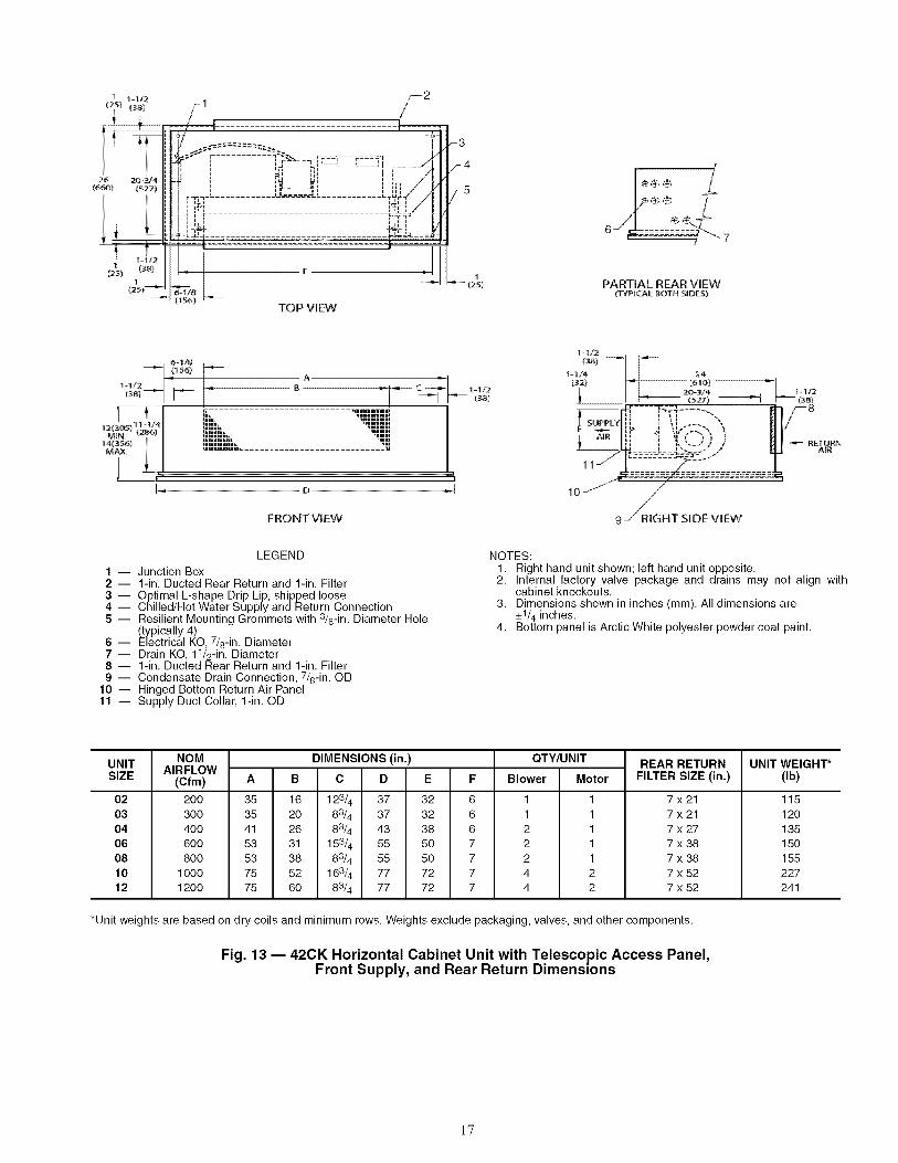
LEGEND
Junction Box1-in. Ducted Rear Return and 1-in. FilterOptimal L-shape Drip Lip, shipped looseChilled/Hot Water Supply and Return ConnectionResilient Mounting Grommets with 3/8-in. Diameter Hole(typically 4)Electrical KO, 7/8-in. DiameterDrain KO, 11/2-in. Diameter1-in. Ducted Rear Return and 1-in. FilterCondensate Drain Connection, 7/8-in. ODHinged Bottom Return Air PanelSupply Duct Collar, 1-in. OD
NOTES:1. Right hand unit shown; left hand unit opposite.2. Internal factory valve package and drains may not align with
cabinet knockouts.3. Dimensions shown in inches (mm). All dimensions are
+1/4 inches.4. Bottom panel is Arctic White polyester powder coat paint.
UNITSIZE
02030406081012
NOM DIMENSIONS (in.)AIRFLOW
(Cfm) A B C D E F
200 35 16 123/4 37 32 6
300 35 20 83/4 37 32 6400 41 26 83_ 43 38 6600 53 31 153/4 55 50 7
800 53 38 83/4 55 50 71000 75 52 163/4 77 72 71200 75 60 83/4 77 72 7
OTY/UNIT
Blower Motor
1 1
1 12 12 1
2 14 24 2
REAR RETURNFILTER SIZE (in.)
7x21
7x217x277x38
7x387x527x52
UNIT WEIGHT*(Ib)
115
120
135150
155
227241
*Unit weights are based on dry coils and minimum rows. Weights exclude packaging, valves, and other components.
Fig. 13 -- 420K Horizontal Cabinet Unit with Telescopic Access Panel,Front Supply, and Rear Return Dimensions
17

2
£
TOP VIEW
,a@@
/4_© @
%J
PARTIAL REAR VIEW(T'(P_CAL @OTN S_DE5}
FRONT VIEW
t-1/2lSS}
-tL2
_321 "_ {61 N
20-_/4 1 - I/2{s27) _l I - (s8}
...... Am13-_'= ..........................................[[ .................................................................................,
11RIGHT SIDE ViEW
I --
2--3--4--5--6--7--
8 --
9--10--11 --12--13--
LEGEND
Contactor BoxStrip Heater High LimitElectric Strip Heater Element1-in. Ducted Rear Return and 1-in. FilterOptimal L-shape Drip Lip, shipped looseChilled/Hot Water Supply and Return ConnectionResilient Mounting Grommets with 3/8-in. Diameter Hole(typically 4)Electrical KO, 7/8-in. DiameterDrain KO,11/2-in. Diameter1-in. Ducted Rear Return and 1-in. FilterCondensate Drain Connection, 7/8-in. ODHinged Bottom Return Air PanelSupply Duct Collar, 1-in. OD
NOTES:1. Right hand unit shown; left hand unit opposite.2. Internal factory valve package and drains may not align
with cabinet knockouts.3. Dimensions shown in inches (mm). All dimensions are
+1/4 inches.4. Bottom panel is Arctic White polyester powder coat paint.
UNITSIZE
02030406081012
NOMAIRFLOW
(Cfm) A
200 35300 35400 41
600 53800 53
1000 75
1200 75
DIMENSIONS (in.) QTY/UNIT
B C D Blower Motor
1 11 12 1
2 12 1
E F
16 123_ 37 32 6
20 83/4 37 32 6
26 83/4 43 38 6
31 153_ 55 50 7
38 83/4 55 50 7
REAR RETURN
52 163/4 77 72 760 83/4 77 72 7
4 2
4 2
FILTER SIZE (in.)
7x217x217x27
7x387x387x52
7x52
UNIT WEIGHT*(Ib)
117122137
152157229
243
*Unit weights are based on dry coils and minimum rows. Weights exclude packaging, valves, and other components.
Fig. 14 -- 420K Horizontal Cabinet Unit with Telescopic Access Panel,Front Supply, Rear Return, and Heater Dimensions
18

rzJ r---]
i
1i-r -FI III
i IIi .iL
llr F-i
I ,11 iii
!_ILL ..................................... ._.;
E 3E _E 3E 3E _E 3zzzz zzzz zzzz zzzz zzzz zzzzL .... _L .... _L .... _L .... _L .... _L .... JL .... _L .... _L .... _L .... _L .... _L .... J
L JL L L L LL .... _L .... _L .... _L .... _L .... _L ....
E
TOP VI[W
4
AI°°¸°L
PA_L R_R VIEW7 _'€_L g'OT_5_S_
-14/2138)
'C ')_ IMINo I I
/ /
P ° -IFRONTVIEW
LEGEND
1 -- Junction Box, 4 in. x 4 in.2- Optional Drip Lip, shipped loose3 -- Mounting Holes (4), Rubber Grommets
have 3/8-in. Diameter Hole4- Piping KO, 11/2-in. Diameter5 -- Electrical KO, 7/8-in. Diameter6- Drain KO, 11/2-in. Diameter7-- Supply Duct Collar8-- Return Connection, 5/8-in. OD.9 -- Optional Rear Return. Consult factory for
collar dimensions.10-- Drain, 7/8-in. OD.11 -- Stamped Bottom Return Air Grille12-- Filter13 -- Stamped Air Supply Grille14 -- Hinged Bottom Access Panel15 -- Supply Connection, 5/8-in. OD.
RIGHTSIDEVIEW
UNITSIZE
0203O406081012
NOTES:1, Right hand unit shown; left hand unit opposite, Coil connection
locations are _+5/8-inch,2, Unit sizes 02 and 03 have one motor, one blower; sizes 04
through 08 have one motor, 2 blowers; sizes 10 and 12 have2 motors, 4 blowers,
3, Bottom access panel has an Arctic White baked finish,4, Refer to supply and return connections above for coil stub-out
locations,5, Not shown: optional drip lip, 3-speed fan switch; wall plate,
1/2-in, fiberglass insulation on inside of casing, closed cell foamon main drain pan,
6, For optional coil connections, view 42CA-203-1 using the FanCoil Builder,
7, Valve package is factory-installed inside the cabinet whenordered with the unit (based on component size),
8, Bottom return or bottom supply is an ETO (engineering to order)request,
9, Dimensions shown in inches (mm),
NOMAIRFLOW
(Cfm)
2OO
3OO4OO6OO
8OO10001200
A
35
354153
537575
DIMENSIONS (in.)
D
37
374355
557777
E
32
32
38
50
50
72
72
OTY/UNIT
Blower Motor
1 1
1 12 12 1
2 14 24 2
FACE AREA(sq ft)
0.83
1.081.351.88
2.313.163.65
UNITWEIGHT*(Ib)
115
120135150
155227241
*Unit weights are based on dry coils and minimum rows. Weights exclude packaging, valves, and other components.
Fig. 15 -- 420K Horizontal Cabinet Unit with Telescopic Access Panel Dimensions
19

t t25) 2 3
....
TOP VIEW
,,i A J"
_4"1_56) /
! ,
I_, D _1
F_NTVI_V
5
-i_5)
f_--4-I/2138)
t-If2._(38)
17_
16..--_
15.."°
_' (isz_--
6
PARTIALREARViEW
9
3o._'4 -I _-Hs2°81-- (78t) -
G>o f 1°
14 13 /_R
RIGHTSIDEVIEW
LEGEND
1 -- Junction Box, 4 in. x 4 in.2 -- Strip Heater High Limit3 -- Electric Strip Heater Element4 -- Optional Drip Lip, shipped loose5 -- Mounting Holes (4), Rubber Grommets
have 3/8-in. Diameter Hole6- Piping KO, 11/2-in. Diameter7 -- Electrical KO, 7/8-in. Diameter8- Drain KO, 11/2-in. Diameter9 -- Supply Duct Collar
10 -- Optional Rear Return. Consult factory forcollar dimensions.
11 -- Drain, 7/8-in. OD.12 -- Stamped Bottom Return Air Grille13-- Filter14 -- Stamped Air Supply Grille15- Hinged Bottom Access Panel16 -- Supply Connection, 5/8-in. OD.17- Return Connection, 5/8-in. OD.
NOTES:1. Right hand unit shown; left hand unit opposite. Coil connection
locations are _+5/8-inch.2. Unit sizes 02 and 03 have one motor, one blower; sizes 04
through 08 have one motor, 2 blowers; sizes 10 and 12 have2 motors, 4 blowers.
3. Bottom access panel has an Arctic White baked finish.4. Refer to supply and return connections above for coil stub-out
locations.5. Not shown: optional drip lip, 3-speed fan switch; wall plate,
1/2-in. fiberglass insulation on inside of casing, closed cell foamon main drain pan.
6. For optional coil connections, view 42CA-203-1 using the FanCoil Builder.
7. Valve package is factory-installed inside the cabinet whenordered with the unit (based on component size).
8. Bottom return or bottom supply is an ETO (engineering to order)request.
9. Dimensions shown in inches (mm).
UNIT SIZE
0203O406081012
NOM AIRFLOW(Cfm)
2OO
3OO4OO6OO
8OO10001200
DIMENSIONS (in.)
A D
35 37
35 3741 4353 55
53 5575 7775 77
E
32
32
38
50
50
72
72
QTY/UNIT
Blower Motor
1 1
1 12 12 1
2 14 24 2
FACE AREA(sq ft)
0.83
1.081.351.88
2.313.163.65
UNITWEIGHT*
(Ib)
117
122
137
152
157
229
243
*Unit weights are based on dry coils and minimum rows. Weights exclude packaging, valves, and other components.
Fig. 16 -- 420K Horizontal Cabinet with Telescopic Access Panel and Electric Heat Dimensions
2O
DISCHARGE AIR OPENING
TOP VI
10"
I_o21
5-3J'4
L .....
L- .....
,,_-----i
"7
I -l/2
t/ _ _4 (38)(i #)
- F_LTE£fl}Er_Nr_,:CUP5
L ..............................................
4-t12
': (_141
1i
"1r .......
JI .........
i
FRONT V]EW
L
_9
24/4( sT_
8 j
7_
_ET_ N{ 3(761
-:._8(41)
5
fr"""""_.
7-;.%_8
_-t/41235)
RIGHTSiDE VIEW
2
_5
_6
LEGEND
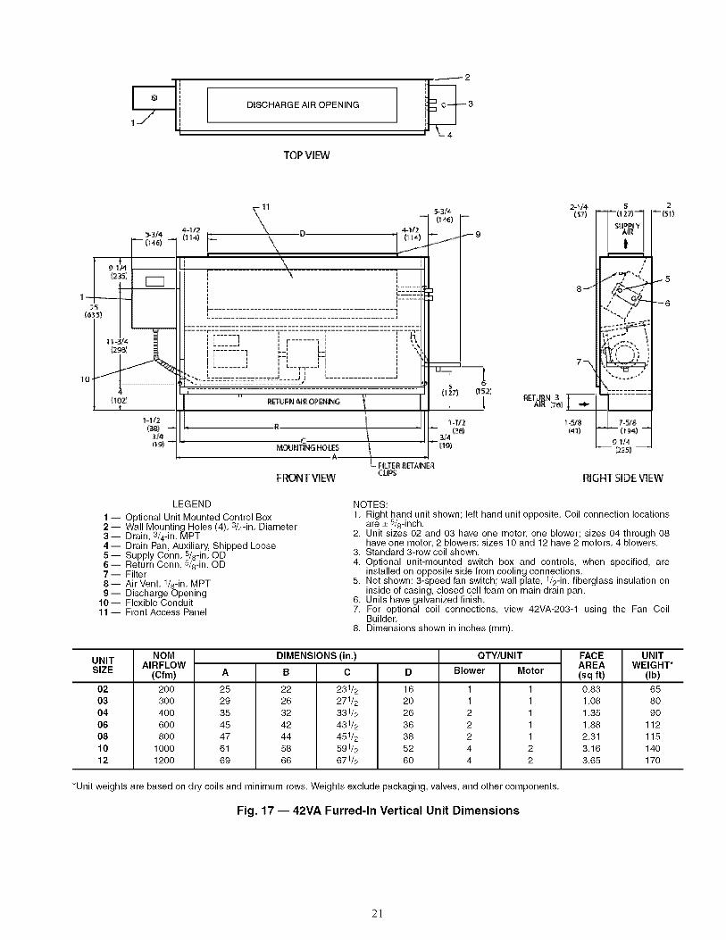
1 -- Optional Unit Mounted Control Box2 -- Wall Mounting Holes (4), 3/4-in. Diameter3- Drain, 3/4-in. MPT4 -- Drain Pan, Auxiliary, Shipped Loose5 -- Supply Conn, 5/8-in. OD6 -- Return Conn, 5/8-in. OD7- Filter8 -- Air Vent, 1/8-in. MPT9-- Discharge Opening
10-- Flexible Conduit11 -- Front Access Panel
NOTES:1. Right hand unit shown; left hand unit opposite. Coil connection locations
are _+5/8-inch.2. Unit sizes 02 and 03 have one motor, one blower; sizes 04 through 08
have one motor, 2 blowers; sizes 10 and 12 have 2 motors, 4 blowers.3. Standard 3-row coil shown.4. Optional unit-mounted switch box and controls, when specified, are
installed on opposite side from cooling connections.5. Not shown: 3-speed fan switch; wall plate, 1/2-in. fiberglass insulation on
inside of casing, closed cell foam on main drain pan.6. Units have galvanized finish.7. For optional coil connections, view 42VA-203-1 using the Fan Coil
Builder.8. Dimensions shown in inches (mm).
UNITSIZE
02030406081012
NOMAIRFLOW
(Cfm)
2OO3OO4OO6OO8OO
10001200
A
25293545476169
DIMENSIONS (in.)
B C
22 231/2
26 271/232 331/242 431/2
44 451/258 591/266 671/2
D
16
20
26
36
38
52
60
QTY/UNIT
Blower Motor
1 11 12 12 12 14 24 2
FACEAREA(sq ft)
0.831.081.351.882.313.163.65
UNITWEIGHT*
(Ib)
658O9O
11211514O17O
*Unit weights are based on dry coils and minimum rows. Weights exclude packaging, valves, and other components.
Fig. 17 -- 42VA Furred-In Vertical Unit Dimensions
21

TOPVIEW
l _ "3J4
_)
11 J
i | nb .... _ r .......... 'I ,i,---r_P.mumi Imm *r..... "m n ! mnnlmm m| m m | _,|mm'" ,I. ..... ' me...... I ' ' \_'"
/'_, III j ........ m,- m Lm : _II_+. | m I n I- ,,-N I _ n.... : f , ........
m n! n n !
r, n i inn nn nnm_| ......... --_! m r _ .... %:::::::::::::T,:==_ _ ................ mmm 5_m_. ....................... _ m_l
,,_i I _ ..... II 1127)REiN NR OPENIiNG
4
,,,',' I:: I
" L I1o j 8-3/4 c 8-3/4
(,22:2) _NT)NG HOLES 122:2)__l_ o l g4/2(240 \ _4_)
FRONTV(EW cups
_-9
7 -_
_ETI__tN )
t-I/213_)
5-'_12 2
Fi_40)"("-'] I_i)
"-4
m
L,-,,2J
RIGHTSlOE'VIEW
LEGEND
1 -- Standard Stamped Supply Grille2- Access Door, Fan Switch3 -- Supply Conn, 5/8-in. OD4 -- Return Conn, 5/8-in. OD5- Drain, 3/4-in. MPT6- Filter7 -- Air Vent, 1/8-in. MPT8-- Front Panel Fastener9- Drain Pan, Auxiliary, Shipged Loose
10- Wall Mounting Holes (4), _/4-in. Diameter11 -- Flexible Conduit12- Fan Switch, 3-speed13 -- Front Access Panel
NOTES:1, Right hand unit shown; left hand unit opposite, Coil connection
locations are _+5/8-inch,2, Unit sizes 02 and 03 have one motor, one blower; sizes 04 through
08 have one motor, 2 blowers; sizes 10 and 12 have 2 motors,4 blowers,
3, Standard 3-row coil shown,4, Cabinet has an Arctic White baked finish,5, Stamped supply grille standard, Optional single or double deflec-
tion grilles available,6, Not shown: 1/2-in, fiberglass insulation on inside of casing, closed
cell foam on main drain pan,7, For optional coil connections, view 42VA-203-1 using the Fan Coil
Builder,8, Dimensions shown in inches (mm),
UNITSIZE
0203
040608
1012
NOMAIRFLOW
(Cfm)
2OO3OO4OO6OO8OO
10001200
A
41455161637785
22263242445866
DIMENSIONS (in.)
C D
35/831/241/4
23/433/441/4
33/4
QTY/UNIT
Blower Motor
1111122
231/2271/2331/2
431/2451/2591/2671/2
171/4211/2
2639395261
1122244
FACEAREA(sq ft)
0.831.081.351.882.313.163.65
*Unit weights are based on dry coils and minimum rows. Weights exclude packaging, valves, and other components.
Fig. 18 -- 42VB Vertical Cabinet Unit Dimensions
UNITWEIGHT*
(Ib)
89
95
116
134
137
169
192
22

1gJ
9-1/4
flr ........ "4 _ I- ........ 1
TOPVIEW
_2
3-1/4
_)
_4
12 _ "'"
€
[17_AL,f/
__.... dJJi r---, !!I'_L ! II
'--Er---L1_I I',cl
Ii "
13 f14
;I iI I
I] _ ,i o
II _ .... LF_
i l--- -4_-
, ,-- 4 I
I
J
r _----_ _ r _ [-11',IIF" ..... L r"ll tl_i c: _#i i r_ f _Li i i i i r L
. I L • i LEE • I I I" "_ _ ....A I l " I J I ' _..................... _ hi
-5"......... :: ..... :::::::::::::::::::::::::: ........ -,"','', [12.7)" RET_JRNAmOKNING "\ i [
C \'\ 8-3/4
M,OU_I_ HOU:_
FRONT _[W _Ps
,-8
j9
"'-10
1-¢]4(32:1
7 j
6"_
I_T_NAIR 17 )
1-1 _:
%g
f_',q
LEGEND
1 -- Standard Stamped Supply Grille2- Access Door, Fan Switch3 -- Supply Conn, 5/8-in. OD4-- Return Conn, 5/8-in. OD5-- Drain, 3/4-in. MPT6-- Filter7- Air Vent, 1/8-in. MPT8-- Front Panel Fastener9 -- Optional Valve Package (inside cabinet)
10-- Drain Pan, Auxiliary, Shipped Loose11 -- Wall Mounting Holes 3/4-in. Diameter12-- Flexible Conduit13-- Fan Switch, 3 speed14-- Access Doors
j3
_4
_5
9- I_
RIGHT SIDE VIEW
NOTES:1. Right hand unit shown; left hand unit opposite. Coil connection
locations are _+5/8-inch.2. Unit sizes 02 and 03 have one motor, one blower; sizes 04
through 08 have one motor, 2 blowers; sizes 10 and 12 have2 motors, 4 blowers.
3. Standard 3-row coil shown.4. Cabinet has an Arctic White baked finish.5. Not shown: 1/2-in. fiberglass insulation on inside of casing,
closed cell foam on main drain pan.6. For optional coil connections, view 42VA-203-1 using the Fan
Coil Builder.7. Valve package is factory-installed inside the cabinet when
ordered with the unit (based on component size).8. Dimensions shown in inches (mm).
UNITSIZE
0203O406081012
NOMAIRFLOW
(Cfm)
2OO3OO4OO6OO8OO
10001200
A
41455161637785
B
DIMENSIONS (in.)
C D
35/831/241/423/433/441/433/4
QTY/UNIT
Blower Motor
1111122
22263242445866
231/2271/2331/2431/2451/2591/2671/2
171/4211/2
263939
521/861
1122244
FACEAREA(sq ft)
0.831.081.351.882.313.163.65
*Unit weights are based on dry coils and minimum rows. Weights exclude packaging, valves, and other components.
Fig. 19 -- 42VF Vertical Cabinet Unit with Slant Top Dimensions
UNITWEIGHT*
(Ib)
9298
1221411441782O5
23

i0 s2/
I
//--J
(DISCHARGE AIR OPENING
.B
A
TOP VIEW
(1s2)
FRON_ VIEW
1-1Z829)
5 I
_TU_N
3_76)
1-1/8(29)
10
I _-If8
RIGHTSi[DE _E_
LEGEND
1 -- Optional Unit Mounted Control Box2 -- Drain Pan, Auxiliary, Shipped Loose3 -- Supply Conn, 5/8-in. OD4 -- Drain, 3/4-in. MPT5 -- Return Conn, 5/8-in. OD6 -- Air Vent, 1/8-in. MPT7 -- Discharge Opening8- Filter
NOTES:1. Right hand unit shown; left hand unit opposite. Coil connection
locations are _+5/8-inch.2. Unit sizes 02 through 04 have one motor, 2 blowers; size 06
has 2 motors, 4 blowers.3. Standard 2-row coil shown.4. Optional unit-mounted switch box and controls, when specified,
are installed on opposite side from cooling connections.5. Height increases by 2 in. with electric heat.6. Not shown: 3-speed fan switch, 1/2-in. fiberglass insulation on
inside of casing, closed cell foam on main drain pan.7. Units have galvanized finish.8. For optional coil connections, view 42VC-203-1 using the Fan
Coil Builder.9. Dimensions shown in inches (ram).
_3
_4
UNIT SIZE
02030406
NOMAIRFLOW
(Cfm)
2OO3OO4OO
6OO
A
23
28
36
50
DIMENSIONS (in.)
B
222735
49
C
17223o
44
QTY/UNIT
Blower Motor
2 12 12 1
4 2
FACE AREA(sq ft)
1.181.532.08
3.06
*Unit weights are based on dry coils and minimum rows. Weights exclude packaging, valves, and other components.
UNITWEIGHT* (Ib)
506072
110
Fig. 20 -- 42VC Furred-In Lowboy Unit Dimensions
24

DISCHARGE AIR OPENING
TOP VIEW
FRO_ VIEW
LEGEND
1 -- Unit-Mounted Control Box (Optional)2- Drain Pan, Auxiliary, Shipped Loose3- Air Vent, 1/8-in. MPT4 -- Supply Conn, 5/8-in. OD5-- Drain, 3/4-in. MPT6-- Return Conn, 5/8-in. OD7- Filter8-- Electrical Sheath Heater Element9-- Discharge Opening
RMGHTSIDEVIEW
NOTES:1. Right hand unit shown; left hand unit opposite. Coil connection
locations are _+5/8-inch.2. Unit sizes 02 through 04 have one motor, 2 blowers; size 06 has
2 motors, 4 blowers.3. Standard 2-row coil shown.4. Optional unit-mounted switch box and controls, when specified,
are installed on opposite side from cooling connections.5. Height increases by 2 in. with electric heat.6. Not shown: 3-speed fan switch, 1/2-in. fiberglass insulation on
inside of casing, closed cell foam on main drain pan.7. Units have galvanized finish.8. For optional coil connections, view 42VC-203-1 using the Fan Coil
Builder.9. Dimensions shown in inches (mm).
3
4
UNIT SIZE
02030406
NOMAIRFLOW
(Cfm)
2OO3OO4OO6OO
A
23
28
36
50
DIMENSIONS (in.)
B
22273549
C
17223044
QTY/UNIT
Blower Motor
2 12 12 14 2
FACE AREA(sq ft)
1.181.532.083.06
*Unit weights are based on dry coils and minimum rows. Weights exclude packaging, valves, and other components.
UNITWEIGHT* (Ib)
5O6O72
110
Fig. 21 -- 42V0 Furred-In Lowboy Unit with Electric Heat Dimensions
25

i ...... 7
I
IL J Jp L-.......J
iL J
I(127)
1211/4
_-1/4
FRONT VIEW RIGHTSIDEVIEW
LEGEND
1 -- Fan Switch, 3-Speed, behind Access Door2-- Front Panel Fastener3-- Stamped Supp_lyGrille4 -- Supply Conn,b/8-in. OD5-- Return Conn, 5/8-in. OD6- Stamped Return Grille7- Filter8-- Air Vent, 1/8-in. MPT9- Optional Valve Package (inside cabinet)
10-- Drain Pan, Auxiliary, with 3/4-in. MPTDrain Connection
11 -- Return Air Grille
NOTES:1. Right hand unit shown; left hand unit opposite. Coil connection
locations are _+5/8-inch.2. Unit sizes 02 through 04 have one motor, 2 blowers; size 06 has
2 motors, 4 blowers.3. Cabinet has an Arctic White baked finish.4. Height increases by 2 in. with electric heat.5. Standard 2-row coil shown.6. Not shown: 1/2-in. fiberglass insulation on inside of casing,
closed cell foam on main drain pan.7. For optional coil connections, view 42VC-203-1 using the Fan
Coil Builder.8. Valve package is factory-installed inside the cabinet when
ordered with the unit (based on component size).9. Dimensions shown in inches (mm).
_4
_5
UNIT SIZE
02030406
NOMAIRFLOW
(Cfm)
200300
400600
A
4146
5468
DIMENSIONS (in.)
B C
22 33427 435 3 5&
49 41/16
17
211/23ol/4433/8
OTY/UNIT
Blower Motor
2 12 1
2 14 2
*Unit weights are based on dry coils and minimum rows. Weights exclude packaging, valves, and other components.
Fig. 22 -- 42VE Cabinet Lowboy Unit Dimensions
FACE AREA(sq ft)
1.181.53
2.083.06
UNITWEIGHT*
(Ib)
72100
108154
26

TOP k4EW
/r _i{i -L-_'-'-'' ii
r----i r---F_ "i k '_t", [ )_. .....E i
1_ ..... 1 "--_qi
i i' 1i i1 ,
ii iL ..... IN
: ; ____a i "r'r ..... %%
k
_411 i i (241) --
1
9
jlO
t6-d:
(2e)
iR_URNAIR -!,.
!_____
1701
t2-1 f4
',i, _ L.I_=_ /= /
L I0-I14
/4
--5
FRONTVi_
LEGEND
1 -- Fan Switch, 3-Speed, behind Access Door2 -- Electrical Sheath Heater Element
-- Stamped SuppslYGrille3 Supply Conn, /8-in. OD5 Return Conn, 5/8-in. OD6-- Stamped Return Grille7-- Filter8-- Air Vent, 1/8-in. MPT9-- Front Panel Fastener
10-- Optional Valve Package (inside cabinet)11 Drain Pan, Auxiliary, with 3/4-in. MPT
Drain Connection12 -- Return Air Grille
RIGHTSIDEVEW
NOTES:1. Right hand unit shown; left hand unit opposite. Coil connection
locations are _+5/8-inch.2. Unit sizes 02 through 04 have one motor, 2 blowers; size 06 has
2 motors, 4 blowers.3. Cabinet has an Arctic White baked finish.4. Height increases by 2 in. with electric heat.5. Standard 2-row coil shown.6. Not shown: 1/2-in. fiberglass insulation on inside of casing,
closed cell foam on main drain pan.7. For optional coil connections, view 42VC-203-1 using the Fan
Coil Builder.8. Valve package is factory-installed inside the cabinet when
ordered with the unit (based on component size).9. Dimensions shown in inches (mm).
UNIT SIZE
02030406
NOMAIRFLOW
(Cfm)
2OO
3OO4OO6OO
A
41
465468
DIMENSIONS (in.)
B C
22 33/427 435 35/849 41/16
17
211/2301/4433/8
QTY/UNIT
Blower Motor
2 1
2 12 14 2
FACE AREA(sq ft)
1.18
1.532.083.06
UNITWEIGHT*
(Ib)
72
100
108154
*Unit weights are based on dry coils and minimum rows. Weights exclude packaging, valves, and other components.
Fig. 23 -- 42VE Cabinet Lowboy Unit with Electric Heat Dimensions
27
I
I
A
II
ITOPVIBN
S_
7_ 7J8 C 781221 _i
I ITOP VIEW
(STANDARDMOD_L_STY
I
(25)q1-
(t 27_
K1251
__z== 5....... 1' ;-- IIi i =1
I I , , I I I, ,, ,, , ,,II I I I Ii L .............. -LL----= i
L--_ ...........r-T _ i
, ,;_,,-_, _'. ............
: " " :: ._ I i I
,i .... i I I
FRONTNEW FRO_ ViEW RIGHTSIDE_EW
LEGEND
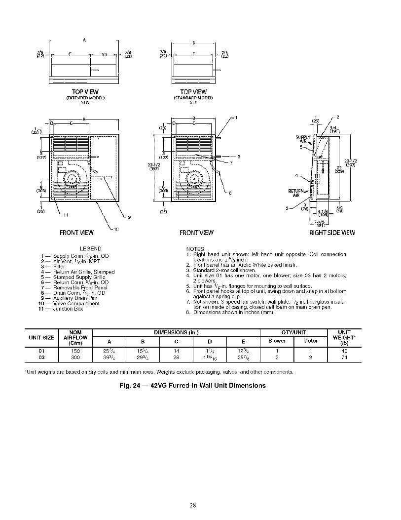
-- Supply Conn, 5/6-in. ODAir Vent, 1/8-in. MPT3- Filter4 -- Return Air Grille, Stamped
-- Stamped Supply GrilleReturn Conn, 5/8-in. OD7-- Removable Front Panel8-- Drain Conn, 7/8-in. OD9- Auxiliary Drain Pan
10-- Valve Compartment11 -- Junction Box
NOTES:1. Right hand unit shown; left hand unit opposite. Coil connection
locations are _+5/8-inch.2. Front panel has an Arctic White baked finish.3. Standard 2-row coil shown.4. Unit size 01 has one motor, one blower; size 03 has 2 motors,
2 blowers.5. Unit has 1/2-in. flanges for mounting to wall surface.6. Front panel hooks at top of unit, swing down and snap in at bottom
against a spring clip.7. Not shown: 3-speed fan switch, wall plate, 1/2-in. fiberglass insula-
tion on inside of casing, closed cell foam on main drain pan.8. Dimensions shown in inches (mm).
UNIT SIZE
0103
NOMAIRFLOW
(Cfm)
1503OO
DIMENSIONS (in.)
A B C D E
253_ 153_ 14 11_ 123/4393_ 293_ 28 115/16 257_
QTY/UNIT
Blower Motor
1 12 2
*Unit weights are based on dry coils and minimum rows. Weights exclude packaging, valves, and other components.
Fig. 24 -- 42VG Furred-In Wall Unit Dimensions
UNITWEIGHT*
(Ib)
4074
28

.........1
6
9(228)
I-3:/4J
4-I/2_I14)-
2
3
TOP VIEW
11
MOUNTING HOLES
16-3_(416)
1
FRONTVIEW
4
/f__ ID RAIN OUTLET
I
(3815-3t4
t lpj '-- 046)[1S) --'7
1-3/4(299) _1
÷T1
C25I
lO_:3N
F g 9)
[lSUPPLY
16-3/8 13-1/2 A;_RC4161 1B43}
--27-1/2 {6gg) --
1H/2
-i , __-_-.+./.._ '7
RIGHT SIDE VIEW
T2
($11!
UNIT NOM DIMENSIONS (in. ± 1_) QTY/UNIT UNITSIZE AIRFLOW WEIGHT*
(cfm) A A' B D' E H Blower Motor (Ib)
06 600 23 32 14 131_ 17 181_ 1 1 64
08 800 28 37 19 131_ 22 231_ 1 1 79
10 1000 32 42 23 141_ 26 271_ 1 1 90
12 1200 37 47 28 141_ 31 321_ 2 2 108
14 1400 42 52 33 141_ 36 371_ 2 2 119
16 1600 47 56 38 131_ 41 421_ 2 2 124
18 1800 52 62 43 141_ 46 471_ 2 2 141
20 2000 56 66 47 141_ 50 511_ 2 2 151
LEGEND
1 -- Motor Junction Box
2-- Motor-Blower Assembly3 -- Electric Strip Heater Element (optional)4 -- Auxiliary Drip Lip (Optional, Shipped Loose)
_-- Tell-Tale Drain (optional)Drain Connection, 7/8-in. OD7 -- Air Vent, 1/8-in. MPT8-- Supply Connection9-- Supply Duct Collar, 1 inch
10-- Return Connection
11 -- Mounting Holes (four, 3/4-in. diameter) haveRubber Grommets with 3/8-in. holes.
*Unit weights are based on dry coils and minimum rows. Weights exclude packaging, valves, and othercomponents.NOTES:
1. Right hand unit shown; left hand unit opposite. Coil connection locations are + 5/8 inch.2. Sizes 06, 08 and 10 have one motor, one blower; sizes 12 through 20 have 2 motors, 2 blowers.3. Standard 4-row coil shown. Other coil option dimensional data available on request.4. For optional coil connections, view 42DA-203-1 using the Fan Coil Builder.5. Fan switch, wall plate not shown.6. Galvanized finish provided as standard.7. Dimensions are in inches (mm).
Fig. 25 -- 42DA Furred-In Ceiling Unit with Electric Heat Dimensions
29
-A
TOP VIEW
1
28q/2(724)
5
7
1-112_38) I
t i12J
DRAIN OUTLET1_-3/4
I" (2_)- 1
3!4
F
FRONT Vl EW
16
3:/4
12
14
OPTIONALR_RR_URN
10-
9 /
2-1/2_64)
2-112
d_e
__11
_4N(32)
RIGHTSIDE VIEW
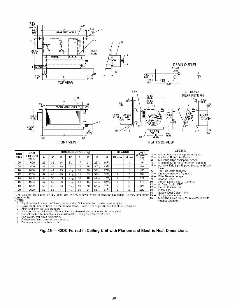
UNIT NOM DIMENSIONS (in. ± 118) QTY/UNIT UNITSIZE AIRFLOW WEIGHT* 1 --
(cfm) A A' B D' E F G H Blower Motor (Ib) 2 --3--
06 600 23 32 14 131/2 17 21 251/4 181/2 1 1 94 4 --
08 800 28 37 19 131/2 22 26 301/4 231/2 1 1 107 5 --
10 1000 32 42 23 141/2 26 30 341/4 271/2 1 1 150 6 --
12 1200 37 47 28 141/2 31 35 391/4 321/2 2 2 169 7 --8--
14 1400 42 52 33 141/2 36 40 441/4 371/2 2 2 174 9 --
16 1600 47 56 38 131/2 41 45 491/4 421/2 2 2 178 10 --
18 1800 52 62 43 141/2 46 50 541/4 471/2 2 2 195 12 --20 2000 56 66 47 141/2 50 54 581/4 511/2 2 2 220 13 --
14--*Unit weights are based on dry coils and minimum rows. Weights exclude packaging, valves, and other 15-components. 16 --NOTES:
1. Right hand unit shown; left hand unit opposite. Coil connection locations are _+5/8 inch.2. Sizes 06, 08 and 10 have one motor, one blower. Sizes 12 through 20 have 2 motors, 2 blowers.3. Filter and filter rack are standard.4. Standard 4-row coil shown. Other coil option dimensional data available on request.5. For optional coil connections, view 42DA-203-1 using the Fan Coil Builder.6. Fan switch, wall plate not shown.7. Galvanized finish provided as standard.8. Dimensions are in inches (ram).
LEGEND
Motor Junction Box Opposite PipingInsulated Return Air PlenumMounting Clips (Shipped Loose)Electrical Strip Heater Element (optional)Auxiliary Drip Lip (Shipped Loose) with 3/8-in.HoleTell-Tale Drain (optional)Drain Connection, 7/8-in. ODFilter Retainer AngleAccess PanelReturn Duct Collar, 21/2 inchesAir Vent, 1/8-in. MPTReturn ConnectionFilter, 1-in.Supply Duct Collar, 1 inchSupply ConnectionMounting Holes (four, 3/4-in. diameter) withRubber Grommet
Fig. 26 -- 42DC Furred-In Ceiling Unit with Plenum and Electric Heat Dimensions
3O
/t 27) F
SUPPLY'AIROPENING
A
TOP VIEW
11
4-(_o2)
8
i'
J_/4 JIt _):
7 _j
_I"URNAIR
' ', /// ',':-.._LJ L
4
FRONT ViEW RIGHT SIDE VIEW
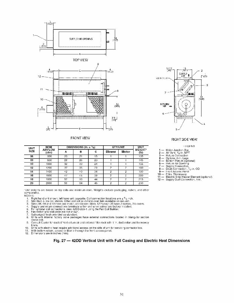
UNITSIZE
06
08
10
12
14
16
18
20
NOM DIMENSIONS (in. ± 1_) QTY/UNIT UNITAIRFLOW WEIGHT*
(cfm) A B C Blower Motor (Ib)
600 23 21 15 1 1 135
800 28 26 20 1 1 145
1000 32 30 24 1 1 155
1200 37 35 29 2 2 180
1400 42 40 34 2 2 190
1600 47 45 39 2 2 200
1800 52 50 44 2 2 215
2000 56 54 48 2 2 230
LEGEND
1 -- Motor Junction Box2 -- Air Vent, 1/8-in. MPT3-- Return Connection4 -- Optional 6-in. Legs5 -- Bottom Return (optional)6-- Return Air Opening7-- Supply Connection8-- Drain Connection, 7/8-in. OD9-- Front Access Panel
10-- Filter, Throwaway11 -- Electric Strip Heater Element (optional)12 -- Supply Duct Connection, 1-in.
*Unit weights are based on dry coils and minimum rows. Weights exclude packaging, valves, and othercomponents.NOTES:
1. Right hand unit shown; left hand unit opposite. Coil connection locations are _+5/8 inch.2. Standard 4-row coil shown. Other coil option dimensional data available on request.3. Sizes 06, 08 and 10 have one motor, one blower. Sizes 12 through 20 have 2 motors, 2 blowers.4. Supply and return connections terminate within unit when valves are factory installed.5. For optional coil connections, view 42DD-203-1 using the Fan Coil Builder.6. Fan switch and wall plate are not shown.7. Galvanized finish provided as standard.8. Units with internal factory valve packages have external connections located in triangular section
above coil.
9. Consult Carrier for ducted front return air and external filter rack with 1-in. duct collar and throwawayfilters.
10. Units with electric heat require additional access on the side of unit for servicing contactor box.11. With bottom return, access to filter is through the front access panel.12. Dimensions are in inches (mm).
Fig. 27 -- 42DD Vertical Unit with Full Casing and Electric Heat Dimensions
31
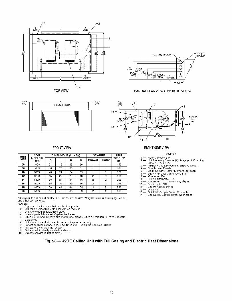
1
c 8
;11 L-h,il L-2_II J4;i i ' i ' iiii , ,,_, , ,,_, /11!iii ' Zi ....i....... .....i: iI I ii I I i _a" ii
ill ', _. ---" .... ----_---_ ii IIiiI I I r_ iiill ,',;. -- ......; llil, i ,, l--tic J i1
qt "* ", r" _1"
TOP VIEW
2
Z 3
4
li- 1/2" {38) D|A,_O, _._ .... j- 718" (22)
is-3!4 (9 el2 i I .,_ I ,_I (4®) I I (229) _:_r_ 345115 J I .,T, L{; I ! 4 ! '+' (_ool_._3s_I "r /
t I j(7_)L,,"
PARTIAL REARVlEW(TYP,BOTH SIDES)
24/2 , Di ¸ 6
_ RETIJRN:L_3. _ _ _ _ AiR
H_ II i i U r',v.,z-,;, / M'l[:il---+-
13 _I ,_, _=_--'r===5--_,-=a ....... IF '77o'+ _"'-'_ It" ........ -"- -'_, I _
FRONTVIEW
UNITSIZE
06
08
10
12
14
16
18
20
NOM DIMENSIONS (in. ± 1_) QTY/UNITAIRFLOW
(cfm) A B C D Blower Motor
600 31 15 15 26 1 1
800 36 20 20 31 1 1
1000 40 24 24 35 1 1
1200 45 29 29 40 2 2
1400 50 34 34 45 2 2
1600 55 39 39 50 2 2
1800 60 44 44 55 2 2
2000 64 48 48 59 2 2
RIGHTSIDEVIEW
LEGENDUNIT
WEIGHT* 1 -- Motor Junction Box(Ib) 2 -- Unit Mounting Channel (2), 14-gage; 4 Mounting
Slots, 1/2-in. x 2-in.150 3 -- Auxiliary Drip Lip (optional, shipped loose)160 4 -- Side Access Panels
170 5 -- Electrical Strip Heater Element (optional)6 -- Supply Air Duct Connection, 1 in.
195 7 -- Manual Air Vent
205 8 -- Filter, Throwaway, 1-in.9 -- Return Air Duct Connection, 21/2 in.
215 10-- Drain, 7/8-in. OD230 11 -- Bottom Access Panel
12-- Drain Pan235 13 -- Coil Inlet, Copper Sweat Connection
14 -- Coil Outlet, Copper Sweat Connection*Unit weights are based on dry coils and minimum rows. Weights exclude packaging, valves,and other components.NOTES:
1. Right hand unit shown; left hand unit opposite.2. Coil stub-out location data available on request.3. Unit fabricated of galvanized steel.4. Internal parts fabricated of galvanized steel.5. Sizes 06, 08 and 10 have one motor, one blower. Sizes 12 through 20 have 2 motors,
2 blowers.6. Units must have drain line pitched and trapped externally.7. For optional coil connections, view 42DA-203-1 using the Fan Coil Builder.8. Fan switch, wall plate not shown.9. Galvanized finished provided as standard.
10. Dimensions are in inches (mm).
Fig. 28 -- 42DE Ceiling Unit with Full Casing and Electric Heat Dimensions
32

1 2
',I[ ', _ ', _" _ IIilII i LF_', ! L2 _ H!II,,11 , , ,,,, , , ,, Iii!1
II ...........i*',',ll!il,,11 ',,_........................-_,...._,' IIiil
o _J '"_1TOP VIEW _ 5
PARTIAL REARVIEW {TYP, BOTH SIDES)
43H_GER :SLO_
FRONT VIEW
m1318 I AIR
(457)
-7
/-8I \ ,_,,.," 7...........
11 J _,-10
RIGHTSIDEVIEW
_9
2"3
I76]
--f
UNIT NOM DIMENSIONS (in. ± 1/8) QTWUNIT UNITAIRFLOW WEIGHT*
SIZE (cfm) A B C D E Blower Motor (Ib)
06 600 31 131/2 14 26 81/2 1 1 150
08 800 36 181/2 20 31 8 1 1 160
10 1000 40 221/2 24 35 8 1 1 170
12 1200 45 271/2 28 40 81/2 2 2 195
14 1400 50 321/2 34 45 8 2 2 205
16 1600 55 371/2 38 50 81/2 2 2 215
18 1800 60 421/2 44 55 8 2 2 230
20 2000 64 461/2 48 59 8 2 2 235
*Unit weights are based on dry coils and minimum rows. Weights exclude packaging, valves, and othercomponents.NOTES:
1. Right hand unit shown; left hand unit opposite.2. Coil stub-out connection data available on request.3. Units fabricated of galvanized steel with an Arctic White baked finish.4. Internal parts fabricated of galvanized steel.5. Sizes 06, 08 and 10 have one motor, one blower. Sizes 12 through 20 have 2 motors, 2 blowers.6. Units must have drain line pitched and trapped externally.7. Stamped supply and return grilles are not available.8. Bottom return air is not available.
9. For optional coil connections, view 42DA-203-1 using the Fan Coil Builder.10. Fan switch and wall plate are not shown.11. Dimensions are in inches (mm).
LEGEND
1 --Junction Box2 -- Return Air Grille, Hinged, Bar Type, with Filter
Frame (Anodized Aluminum Only)3 -- Unit Mounting Channel (2), 14-gage; 4 Mounting
Slots, 1/2 in. x 2-in.4 --Auxiliary Drip Lip5 -- Electric Strip Heater Element (optional)6 --Coil Inlet, Copper Sweat Connection7 --Coil Outlet, Copper Sweat Connection8 -- Manual Air Vent9 -- Filter, Throwaway10-- Bottom Access Panel11--Drain, 7/8-in. OD12--Drain Pan Insulated with Styrofoam13--Side Access Panel (2)14-- Supply Air Grille (Double Deflection)
Fig. 29 -- 42DF Exposed Ceiling Unit with Supply and Return Grille and Electric Heat Dimensions
33

CR--CS--D --HR--HS--R --S --
_HFI H_: D CR (gl h,II iII' SGA 'I',! *PIPE !',Ii iI',, OPTION ,',q
3-5/8(9_
LEGEND
Cold Water ReturnCold Water SupplyDrainHot Water ReturnHot Water SupplyReturnSupply
, 2423 -,,_. 17 I-117
22 J
20 -,_ ....
19 .....
1 8 ',_
17 _
16 m
#E
FRONTVIEW
_,_14
"-"--15
TOP VIEW
H
L
1C
1F'H_
1113
lO
963 54
11600) (1372)8
, s(Ta
_.___...-.-4
j.--5J
88(2558){ NOTE 7)
SIDE VIEW
000I All _isersaM
tangent toback plate
ITEM
1
2
3
4
5
6
7
8
9
10
11
12
13
14
15
16
17
18
19
20
21
22
23
24
DESCRIPTION
Electrical Knockouts
3-in. Expanded Section
Strip Heater (Optional)
Limit Switch**1-1- (Optional)
1/2-in. Isolation Ball Valves**
Flexible Drain Tube/P-Trap
Coil 1/2-in. OD Copper Tube
Filter, Throwaway, 1-in."
Return Air Opening
Air Vent Manual
Molex Connector for Field-Installed Stat
Control Box
Knockout (For Optional Remote Mounting)
Riser Supply and Return (Copper)
Riser, Drain (Copper)
Drain Pan
Acoustical Bypass Panel
Blower
Motor, 3-Speed PSC, with Quick Connect
Access Panel (Control Box)
Control Opening (Surface Mount Stat)
Duct Collar, 1/2-in. Extension (Typical)
Supply Air Opening(s)
Top Supply Collar 1-in Extension(Optional)
QTY
1
3/5
1
1
2/4
1
1
1
1
1
1
1
2
2/4
1
1
1
1
1
1
1
1/2/3
1/2/3
1
*Drawingprovidedforreferenceonly. Dimensions mayvarywithoptionsordered.NOTES:
1.2.3.4.5.6.
lO9:
11.12,
Units are fabricated of galvanized steel with a 16-gage galvanized fan deck.All risers are insulated with (1/2-in. or 3/4-in. thick) closed cell insulation.Thermostats shipped loose for field connection.Risers are piped to coil with valves as specified.Blower, motor valves coil, and filter are accessible through the return air opening.Unit and control box are insulated.Riser length = floor to floor +2 in., maximum riser length = 119 inches.Maximum riser size is 21/2-in. diameter. If larger sizes are required, please consult the factory.Expansion loops in hot water heating circuits as required.A 9-in. x 21/4-in. slot is provided in the inside back panel for coil connection penetration to permit expansionand contraction of risers. Care must be taken to position the risers so that coil connection is at center of slot.Drawing is pictorial (see unit arrangements for actual supply and return air orientation).All dimensions are in inches.
NOMUNIT AIRFLOW Single Supp_SIZE
(cfm) A B
03 300 14 8
04 400 14 12
06 600 18 10
08 800 18 12
10 1000 -- --
12 1200 -- --
DIMENSIONS (in.) UNITDouble Supp_ Top Supp_ WEIGHTt
E G H I (Ib)A B C D
14 6 14 10 17 11_ 11_ 14 180
14 6 14 10 17 11_ 11_ 14 225
18 6 16 12 20 1 2 18 240
18 6 16 12 20 1 2 18 260
22 8 18 16 24 1 3 22 280
22 8 18 16 24 1 3 22 305
1-Unit weights are based on dry coils and minimum rows. Weights exclude packaging, valves, and other components.
**Factory-Installed.1-1-Field-Installed.
Fig. 30 -- 42SG Furred-In Stack Dimensions
34

3(76__ _I L_3-5!8D2)
HIHR H_; D C_ C_; In lqI SHA iI I
I I II
OPTIONI IL r ....... 3 J
19"
18 ...........
1F
JLEGEND
CR i Cold Water ReturnCS -- Cold Water Supply
_R -- DrainHot Water ReturnHS -- Hot Water SupplyR -- ReturnS -- Supply
[3[3[3
-Hflqflflflflfl4"H44flqq444-H-H:-H-H-HH+FFFFFH
_ +H-I-H+_ 3__,,13
,, _ _i_14
i i
i
FRONT VIEW
TOP Vl EW
tS(127)
lO
(NOTE 7)
SIDE VIEW
ITEM DESCRIPTION
1 Full Riser Chase
2 Electrical Knockouts
3 3-in• Expansion Section
4 Strip Heater (Optional)
5 Limit Switch "1-1-(Optional)
6 1/2-in• Isolation Ball Valves *_
7 Flexible Drain Tube/P-Trap
8 Drain Pan
9 Coil 1/2-in• OD Tube
10 Filter Throwaway, 1-in. *_
11 Air Vent, Manual
12 Control Box
13 Cabinet Camlod ®Fasteners
14 3-Speed Switch (Optional)
15 Electrical Access Panel
16 Riser, Supply and Return (Copper)
17 Riser, Drain (Copper)
18 Return Air Panel
19 Motor 3-Speed, PSC
20 Blower
21 Thermostat (Optional)
22 Hinged Control Access Door
23 Double Deflection Steel Core Grille Assembly
**Factory-Installed.1-1-Field-Installed.
OTY
1
1
3/5
1
1
2/4
1
1
1
1
1
1
2
1
1
2/4
1
1
1
1
1
1
1
*Drawing provided for reference only. Dimensions may vary with options ordered.NOTES:
1. Units are fabricated of 18-gage galvanized steel with a 16-gage galvanized fan deck, painted with Arctic White.2. Risers are piped to coil with valves as specified•3• Blower, motor valves coil, and filter are accessible through the return air opening.4• Unit and control box are insulated•
• Riser length = floor to floor +2 in., maximum riser length = 119 inches•• Maximum riser size is 21/2-in• diameter• If larger sizes are required, please consult the factory.
• Expansion loops in hot water heating circuits as required.• A 9-in• x 21/4-in• slot is provided in the inside back panel for coil connection penetration to permit expansion andcontraction of risers• Care must be taken to position the risers so that coil connection is at center of slot•
9• Drawing is pictorial (see unit arrangements for actual supply and return air orientation).10. 42SHA available in front return only.11. All dimensions are in inches.
NOM DIMENSIONS (in.)UNIT AIRFLOW Single Supply Double SupplySIZE C D E F G
(cfm) A B A B
03 300 14 8 14 6 17 22318 21/2 221/8 143/4
04 400 14 12 14 8 17 223/8 21/2 221/8 143/4
06 600 14 12 14 8 20 253/8 21/2 265/8 173/4
08 800 14 16 14 10 20 253/8 21/2 265/8 173/4
10 1000 18 16 14 12 24 293/8 21/2 311/8 173/4
12 1200 18 16 14 12 24 293/8 21/2 311/8 173/4
1-Unit weights are based on dry coils and minimum rows. Weights exclude packaging valves and other components
UNITWEIGHT1"
(Ib)
202
247
262
286
311
336
Fig. 31 -- 42SH Cabinet Dimensions
35
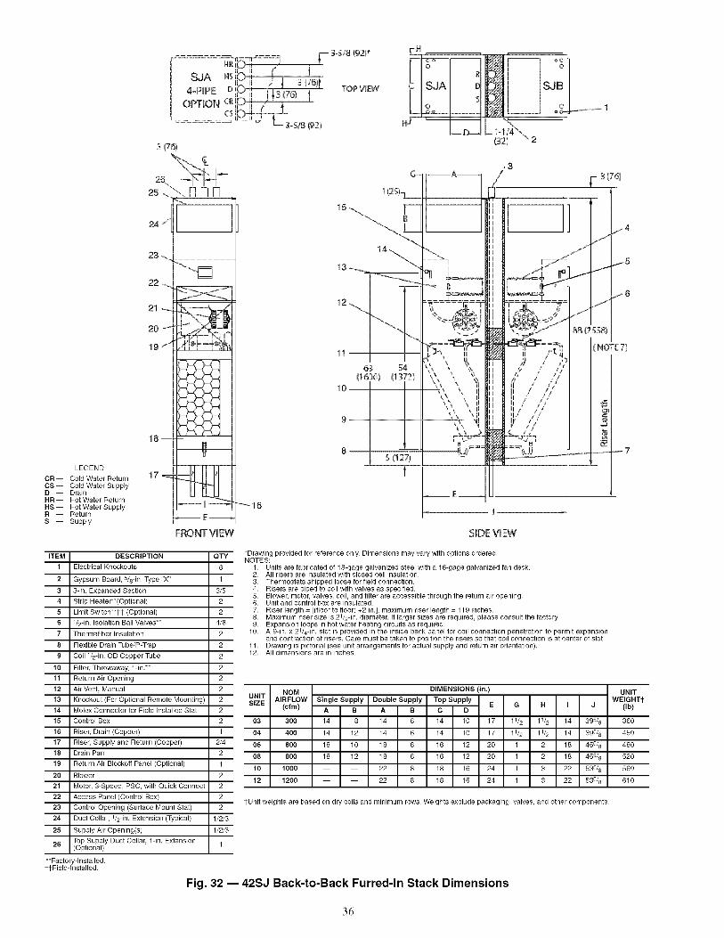
- ........ -_-- :-= F- 3-s.¢8(92)*
uT. il / ! t v_Jr _..........
OPTIONL"I_ ',[/ '_
-5/_(92}
D
S
SJB
o 1
LEGEND
CR-- Cold Water ReturnCSi Cold Water SupplyD-- DrainHR-- Hot Water ReturnHSi Hot Water SupplyR i ReturnS i Supply
i76)
26\25......\ [-1N N
24 /
22_
20_ @
19 "*""
18---
E--
F_ONT VIEW
-"_ 16
11
(1610
,3
_- 3 (76)
r-_- :
ii
4 / ;7',I,¢,I _ , y
T
SLIDEVIEW
ITEM
1
2
3
4
5
6
7
8
9
10
11
12
13
14
15
16
17
18
19
2O
21
22
23
24
25
26
DESCRIPTION
Electrical Knockouts
Gypsum Board 5/8-in. Type "X"
3-in. Expanded Section
Strip Heater**(Optional)
Limit Switch**1-1 - (Optional)
V2-in. Isolation Ball Valves**
Thermafiber Insulation
Flexible Drain Tube/P-Trap
Coil V2-in. OD Copper Tube
Filter, Throwaway, 1-in/*
Return Air Opening
Air Vent Manual
Knockout (For Optional Remote Mounting)
Molex Connector for Field Installed Stat
Control Box
Riser, Drain (Copper)
Riser Supply and Return (Copper)
Drain Pan
Return Air Blocko# Panel (Optional)
Blower
Motor 3-Speed, PSC with Quick Connect
Access Panel (Control Box)
Control Opening (Surface Mount Stat)
Duct Collar, V2-in. Extension (Typical)
Supply Air Opening(s)
Top Supply Duct Collar 1-in. Extension(Optional)
OTY
6
1
3/5
2
2
4/8
2
2
2
2
2
2
2
2
2
1
2/4
2
1
2
2
2
2
1/2/3
1/2/3
1
*Drawing provided for reference only. Dimensions may vary with options ordered.NOTES:
1• Units are fabricated of 18-gage galvanized steel with a 16-gage galvanized fan deck•2• All risers are insulated with closed cell insulation.3• Thermostats shipped loose for field connection.4• Risers are piped to coil with valves as specified•5• Blower, motor valves coil, and filter are accessible through the return air opening•6• Unit and control box are insulated.
• Riser length = floor to floor +2 in. , maximum riser length = 119 inches•• Maximum riser size is 2V2-in• diameter• If larger sizes are required, please consult the factory.9• Expansion loops in hot water heating circuits as required.
10. A 9-in. x 2V4-in• slot is provided in the inside back panel for coil connection penetration to permit expansionand contraction of risers. Care must be taken to position the risers so that coil connection is at center of slot.
11• Drawing is pictorial (see unit arrangements for actual supply and return air orientation).12• All dimensions are in inches.
NOM DIMENSIONS (in.)UNIT AIRFLOW Single Supply Double Supply Top SupplySIZE E G H I J
(cfm) A B A B C D
03 300 14 8 14 6 14 10 17 11_ 11_ 14 395_
04 400 14 12 14 6 14 10 17 1_ 1_ 14 395_
06 600 18 10 18 6 16 12 20 1 2 18 455_
08 800 18 12 18 6 16 12 20 1 2 18 455_
10 1000 -- -- 22 8 18 16 24 1 3 22 535_
12 1200 -- -- 22 8 18 16 24 1 3 22 535_
?Unit weights are based on dry coils and minimum rows. Weights exclude packaging, valves, and other components
**Factory-Installed•1-1-Field-Installed.
Fig. 32 -- 42SJ Back-to-Back Furred-In Stack Dimensions
UNITWEIGHTI"
(Ib)
36O
45O
48O
52O
56O
610
36
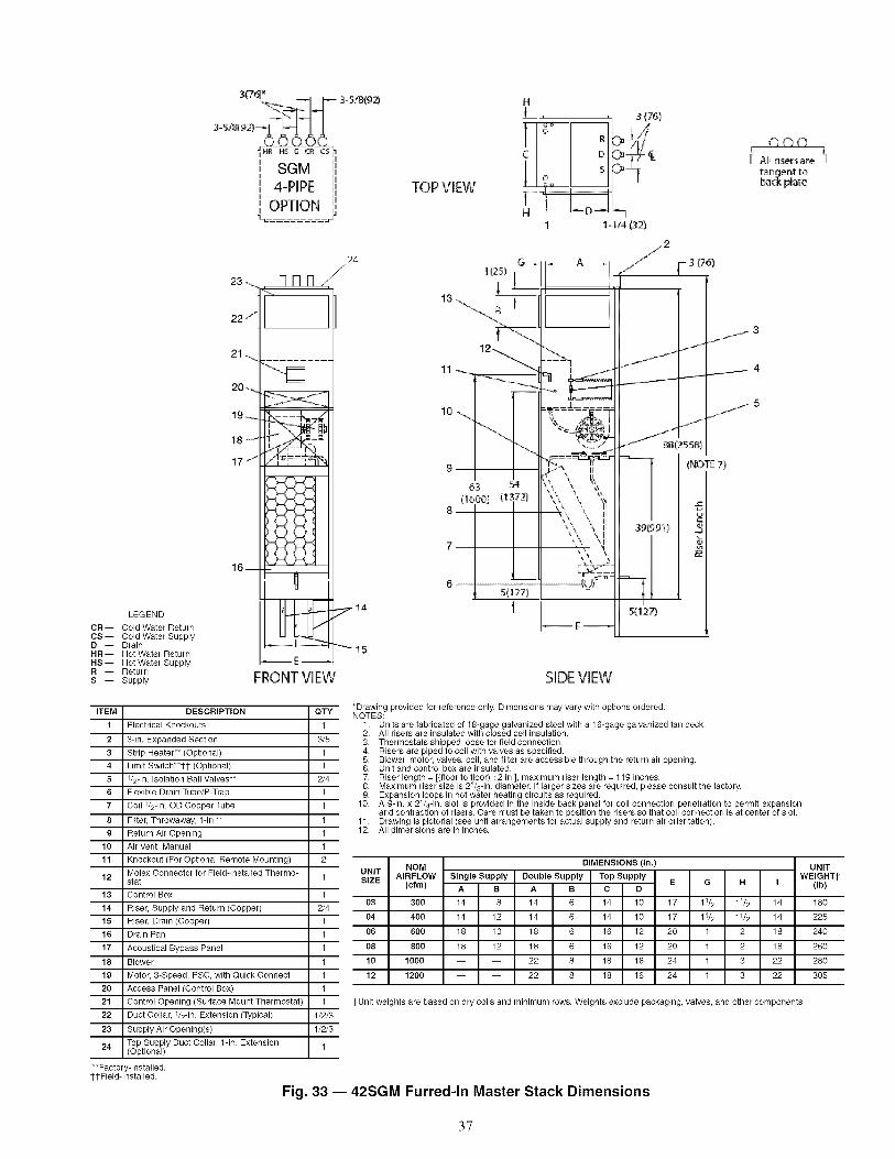
LEGEND
CR i Cold Water ReturnCS i Cold Water SupplyD -- DrainHRi Hot Water ReturnHSi Hot Water SupplyR -- ReturnS -- Supply
_:_ 3-518199
3-S/8(92) ....
i i i
'I eO-M I'Ii _J _...A ii
i! 4-PIPE !i
_ OPTION ;
24/
23.... Allfl _/
22 j
21-...
17 _'_ _ #,_=_%
_: H Hi
16--
U
II kl I1./"
FRONT VIEW
TOP VIEW
HL
1C
1FH
,__ s(761
1-_/4P2i
G_
i
I63 54
1
I _i_ ,,¸
.... / ......
k k ._ iik "_ II
....................................._jj;-
E
2
IJ
8812:5 581
339199_)
S{127)
SIDE VIEW
_y_ 3
j4
_j_ 5
(NOTE 7)
©©ot Allri_rsate f
tange_t to,ba_k plate
ITEM
1
2
3
4
5
6
7
8
9
10
11
12
13
14
15
16
17
18
19
2O
21
22
23
24
DESCRIPTION
Electrical Knockouts
3-in Expanded Section
Strip Heater** (Optional)
Limit Switch**1-1- (Optional)
1/2-in• Isolation Ball Valves**
Flexible Drain Tube/P-Trap
Coil 1/2-in. OD Copper Tube
Filter, Throwaway, 1-in.**
Return Air Opening
Air Vent Manual
Knockout (For Optional Remote Mounting)
Molex Connector for Field-Installed Thermo-stat
Control Box
Riser Supply and Return (Copper)
Riser, Drain (Copper)
Drain Pan
Acoustical Bypass Panel
Blower
Motor 3-Speed, PSC with Quick Connect
Access Panel (Control Box)
Control Opening (Surface Mount Thermostat)
Duct Collar, 1/2-in. Extension (Typical)
Supply Air Opening(s)
Top Supply Duct Collar, 1-in. Extension(Optional)
OTY
1
3/5
1
1
2/4
1
1
1
1
1
2
1
1
2/4
1
1
1
1
1
1
1
1/2/3
1/2/3
1
*Drawing provided for reference only. Dimensions may vary with options ordered.NOTES:
1. Units are fabricated of 18-gage galvanized steel with a 16-gage galvanized fan deck•2. All risers are insulated with closed cell insulation.3• Thermostats shipped loose for field connection.4• Risers are piped to coil with valves as specified•5• Blower, motor valves coil, and filter are accessible through the return air opening•6• Unit and control box are insulated.
• Riser length = floor to floor +2 in•, maximum riser length = 119 inches•• Maximum riser size is 21/2-in• diameter• If larger sizes are required, please consult the factory.
9• Expansion loops in hot water heating circuits as required.10. A 9-in. x 21/4-in. slot is provided in the inside back panel for coil connection penetration to permit expansion
and contraction of risers. Care must be taken to position the risers so that coil connection is at center of slot.11• Drawing is pictorial (see unit arrangements for actual supply and return air orientation).12. All dimensions are in inches•
NOV DIMENSIONS (in.)UNITSIZE AIRFLOW Single Supply Double Supply Top Supply
E G H(cfm) A B A B C D
03 300 14 8 14 6 14 10 17 11/2 11/2 14
04 400 14 12 14 6 14 10 17 11/2 11/2 14
06 600 18 10 18 6 16 12 20 1 2 18
08 800 18 12 18 6 16 12 20 1 2 18
10 1000 -- -- 22 8 18 16 24 1 3 22
12 1200 -- -- 22 8 18 16 24 1 3 22
UNITWEIGHTt
I (Ib)
180
225
240
260
280
3O5
1-Unit weights are based on dry coils and minimum rows Weights exclude packaging, valves, and other components.
**Factory-Installed•1-1-Field-Installed.
Fig. 33 -- 42SGM Furred-In Master Stack Dimensions
37

_.U.__LL_ _ _ .U._.I.L_C5 C_ D HS HR
SGS_PIPE
OPTIONt
TOP VIEW
H
L,
If°C
loLJ
N D -_1-1/4 (32)
(76)
20 _._._
18 .....
17 ..... "
16 _
LEGEND
CR-- Cold Water ReturnCS -- Cold Water SupplyD -- DrainHR-- Hot Water ReturnI-IS -- Hot Water SupplyR -- ReturnS -- Supply
15--
ITEM DESCRIPTION
1 Electrical Knockouts
2 Strip Heater** (Optional)
3 Limit Switch**1-1- (Optional)
4 1/2-in. Isolation Ball Valves**
5 Coil Stub Outs
6 Shipping Brace
7 Flexible Drain Tube/P-Trap
8 Coil 1/2-in. OD Copper Tube
9 Filter, Throwaway, 1-in.**
10 Return Air Opening
11 Air Vent, Manual
12 Knockout (For Optional Remote Mounting)
13 Molex Connector for Field-Installed Stat
14 Control Box
15 Drain Pan
16 Return Air Blockoff Panel (Optional)
17 Blower
18 Motor, 3-Speed, PSC, with Quick Connect
19 Access Panel (Control Box)
Control Opening (Surface Mount Thermo-20 stat)
21 Duct Collar, 1/2-in. Extension (Typical)
22 Supply Air Opening(s)
Top Supply Duct Collar 1-in. Extension23 (Optional)
**Factory-Installed.1-1-Field-Installed.
23
/
E
FRONT VIEW
QTY
1 1.
1 2,3.
1 4.
2/4 5.6.
2/4 7.
2/4 9:1 10.
1 11.1 12.
1
1
2
1
1
1
1
1
1
1
1
1/2/3
1/2/3
1
11
_D_
SIDEVIEW
*Drawing provided for reference only. Dimensions may vary with options ordered.NOTES:
Units are fabricated of 18-gage galvanized steel with a 16-gage galvanized fan deck.All risers are insulated with closed cell insulation.Thermostats shipped loose for field connection.Risers are piped to coil with valves as specified.Blower, motor, valves, coil, and filter are accessible through the return air opening.Unit and control box are insulated.Riser length = floor to floor +2 in., maximum riser length = 119 inches.Maximum riser size is 21/2-in. diameter. If larger sizes are required, please consult the factory.Expansion loops in hot water heating circuits as required.A 9-in. x 21/4-in. slot is provided in the inside back panel for coil connection penetration to permit expansion andcontraction of risers. Care must be taken to position the risers so that coil connection is at center of slot.Drawing is pictorial (see unit arrangements for actual supply and return air orientation).All dimensions are in inches.
UNIT NOMSIZE AIRFLOW Single Supply
(cfm) A B
03 300 14 8
04 400 14 12
06 600 18 10
08 800 18 12
10 1000 -- --
12 1200 -- --
DIMENSIONS (in.) UNIT
Double Supply Top Supply WEIGHT1"E G R I (Ib)
A B C D
14 6 14 10 17 11/2 11/2 14 162
14 6 14 10 17 11/2 11/2 14 203
18 6 16 12 20 1 2 18 216
18 6 16 12 20 1 2 18 234
22 8 18 16 24 1 3 22 252
22 8 18 16 24 1 3 22 275
1-Unit weights are based on dry coils and minimum rows. Weights exclude packaging, valves, and other components.
Fig. 34 -- 42SGS Furred-In Slave Stack Dimensions
38
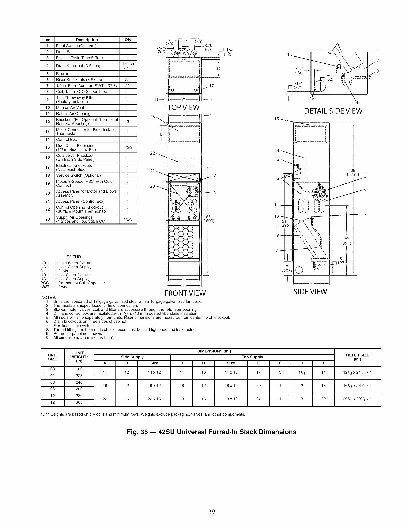
item
1
2
3
4
5
6
7
8
9
10
11
12
13
14
15
16
17
18
19
20
21
22
23
Description
Float Switch (Optional)
Drain Pan
Flexible Drain Tube/P-Trap
Drain Knockout (3 Sides)
Blower
Riser Knockouts (3 Sides)
1/2 in. Flare Adaptor (SWT x 37.5)
Coil, 1/2 in. OD Copper Tube
in. Throwaway Filter(Factory Installed)
Manual Air Vent
Return Air Opening
Knockout (For Optional ThermostalRemote Mounting)
Molex Connector for Field-InstalledThermostat
Control Box
Duct Collar Extension(1/2 in. Side, 1 in. Top)
Outside Air Knockout(On Each Side Panel)
Electrical KnockoutsNear Each Side)
Service Switch (Optional)
Motor, 3-Speed, PSC, with QuickConnect
Access Panel for Motor and BlowerAssembly
Access Panel (Control Box)
Control Opening KnockoutSurface Mount Thermostat)
Supply Air Openings(4 Sides and Top, Stitch Cut)
LEGEND
CR -- Cold Water ReturnCS -- Cold Water SupplyD -- DrainHR -- Hot Water ReturnHS -- Hot Water SupplyPSC -- Permanent Split CapacitorSWT-- Sweat
Oty
1
1
1
1 eachside
1
2/4
2/4
1
1
1
1
3
1
1
1/2/3
1
1
1
1
1
1
1
1/2/3
3-sJ 1-1J4(92)__,,,,Z,h,_"_ _ ] (32)
i iT
HdC----C----II--H
22 --_
2 0 -_
TOP VI EW_A_
L__"m
_-_ r_ ,-_r _
FRONTVIEWNOTES:
1. Units are fabricated of 18-gage galvanized steel with a 16-gage galvanized fan deck.2. Thermostats shipped loose for field connection.3. Blower, motor, valves, coil, and filter are accessible through the return air opening.4. Unit and control box are insulated with 1/2-in. (13 mm) coated fiberglass insulation.
DF
m
I 18
19
631600)
5. All risers will ship separately from units. Riser dimensions are measured from centerline of knockout.6. Drain knockouts on three sides of cabinet.7. Flex hoses ship with unit.8. Thread fittings on both ends of flex hoses must be field tightened and leak tested.9. Return air panel not shown.
10. All dimensions are in inches (mm).
15 _
13 ...........
12
11
(203)
-f
Z I4
DETAIL SIDE VIEW
iiiiIiii
£-!_-J........._,,.......,-T--q
,"'I,"'I_,_I III ',III-
,,-,,,,,,_,=._'-,',,',,
22>
88
(22359_ 5
39
(991)
#(127) I
[_E= _ '
SIDEVIEW
UNITUNIT WEIGHT*SIZE (Ib)
03 180
04 225
06 240
08 260
10 280
12 305
DIMENSIONS (in.)
Side Supply Top Supply
B Size C D Size E
14 12 14 x 12 14 10 14 x 10 17 3 11/2 14
18 12 18 x 12 16 12 16 x 12 20 1 2 18
22 16 22 x 16 18 16 18 x 16 24 1 3 22
FILTER SIZE(in.)
121/2 x 241/4 x 1
161/4 x 263/4 x 1
201/2 x 291/4 x 1
*Unit weights are based on dry coils and minimum rows. Weights exclude packaging, valves, and other components.
Fig. 35 -- 42SU Universal Furred-In Stack Dimensions
39

3-5/8 I I I 3-5/8I +'-.-I l"-" (92) 1-1/4
(92)-'--)..<-_K.J.._iHR'tHStlD,_C_U_CS'l" "1"_" "l" _" [-- (32)
[I ITOP VIEW
25\
]B
L24
22
_A_ _F
20
- 21
63(1600)
_E_
FRONTVIEWLEGEND
CR -- Gold Water Return
CS -- Gold Water SupplyD -- DrainHR -- Hot Water Return
HS -- Hot Water SupplyPSC -- Permanent Split CapacitorSWT- Sweat
17
51(1295)
11
10
1 _"__L_'----_/ 23
i-i/4 l I,'-1"_ ',%_jl I
4
88
(2235_) 7
/I j8
(991)I
DETAIL SIDE VIEW
SIDEVIEW
NOTES:1. Units are fabricated of 18-gage galvanized steel with a 16-gage galvanized fan deck.2. Thermostats shipped loose for field connection.3. Blower, motor, valves, coil, and filter are accessible through the return air opening.4. Unit and control box are insulated with 1/2-in. (13 mm) coated fiberglass insulation.5. All risers will ship separately from units. Riser dimensions are measured from centerline of
knockout.6. Drain knockouts on three sides of cabinet.7. Flex hoses ship with unit.8. Thread fittings on both ends of flex hoses must be field tightened and leak tested.9. Return air panel not shown.
10. All dimensions are in inches (mm).
Item
1
2
3
4
5
6
7
8
9
10
11
12
13
14
15
16
17
18
19
20
21
22
23
24
25
Description
Float Switch (Optional)
Drain Pan
Flexible Drain Tube/P-Trap
Drain Knockout (3 Sides)
Limit Switch (Factory Installed)
Strip Heater
Blower
Riser Knockouts (3 Sides)
1/2 in. Flare Adaptor (SWT x 37.5)
Coil, 1/2 in. OD Copper Tube
in. Throwaway Filter(Factory Installed)
Manual Air Vent
Return Air Opening
Knockout (For OptionalThermostat Remote Mounting)
Molex Connector forField-Installed Thermostat
Control Box
Duct Collar Extension(1/2 in. Side, 1 in. Top)
Outside Air KnockoutOn Each Side Panel)
Electrical KnockoutsNear Each Side)
Service Switch (Optional)
Motor, 3-Speed, PSC,with Quick Connect
Access Panel for Motor and BlowelAssembly
Access Panel (Control Box)
Control Opening KnockoutSurface Mount Thermostat)
Supply Air Openings(4 Sides and Top, Stitch Cut)
UNIT UNITWEIGHT*
SIZE (Ib)
03 182
04 227
06 242
08 262
10 282
12 307
DIMENSIONS (in.)
Side Supply Top Supply
B Size C D Size E
14 12 14 x 12 14 10 14 x 10 17 3 11/2 14
18 12 18 x 12 16 12 16 x 12 20 1 2 18
22 16 22 x 16 18 16 18 x 16 24 1 3 22
*Unit weights are based on dry coils and minimum rows. Weights exclude packaging, valves, and other components.
Fig. 36 -- 42SU Universal Furred-In Stack with Heater Dimensions
Oty
1
1
1
1 eachside
1
1
1
2/4
2/4
1
1
1
1
3
1
1
1/2/3
1
1
1
1
1
1
1
1/2/3
FILTER SIZE(in.)
121_ x 24 l& x l
161&x 263&x 1
201_x 291&x 1
40

3 3 3 3(76)_._lJr--(76) (76)--r_Jr _ (76)
3 5/8 3-518,Q�,-_.._,r._!. [--(2) 1-1/4 .[ .[.[ 1-1/4_J _ .F_,_._ _ - _{o_ '
!_ 1"1" 7_1_ I (32) _,"D,"ic9 ___[ (32)
111 IF................ /F--[111II I(280) If il I(280)L ' 'f ELECTRICAL ................. J._____t
I_e , J KNOCKOUTS ...._,, _IIL e_ L___
-736- IL 24 3 II 24 /( )_ (610)_ (76)_11_ (610)------I
4-PIPE 2-PIPE
RISER--KNOCKOUTS
28(711)
LEGEND
CR -- Cold Water ReturnCS -- Cold Water SupplyD -- DrainHR -- Hot Water ReturnHS -- Hot Water SupplyPSC -- Permanent Split CapacitorSWT- Sweat
__3O(762)
SERVICEACCESS PANEL
39(991)
-- MOTOR/BLOWER,3 SPEED, PSC,HIGH STATIC CONTROL BOX
66
(1676)
_ SLVVZRX 3715
ADAPTER
DRAIN PAN
(610)_ (127)
NOTES:1. Unit measurements on drawings are shown in inches (millimeters).2. Units are fabricated of galvanized steel with a 16 gage galvanized fan deck.3. Blower, motor, valves, coil, and filter are accessible through the return air opening.4. Unit and control box are insulated with 1/2-in. (13 mm) coated fiberglass insulation.5. Maximum riser size is 2 1/2-in. (64 mm) diameter. If larger sizes are required, please consult the factory.6. This drawing is pictorial. (See unit arrangements for actual supply and return air orientation.)7. Riser length = [floor to floor + 2-in. (51 mm)]. Maximum riser length is 119-in. (3023 mm).8. Unit shipping weight is approximately 390 Ib (176 kg).
Fig. 37 -- 42SM Mega Furred-In Stack Dimensions
41

PANELDIMENSIONS(in.)PANEL NO. UNIT UNIT SIZE
03, 0442SG,SJ, 06, 08
SU10, 12
42SM 14,16,20
03, 04
42SG,SJ 06, 08
10, 12
03, 04
42SG,SJ 06, 08
10, 12
A
15.5
19.5
23.5
29.5
15.5
19.5
23.5
15.2
19.2
23.2
NOTE: Dimensions in inches.
55.5
PANEL NO. 1
61.1
_,_A_
® ®
: i
PANELN©.2
,_A _
55.3
PANEL NO. 3
I* A *1® ®
61.1
m i
m
m
m im
i !m
i !
PANEL NO. 2 WITHOUT DOOR
52.5
® ®
PANEL NO. 1 FOR 42SU
60.5
_------- A ------------_
PANEL NO. 1 FOR 42SM
Fig. 38 -- Return-Air Wall Panels for Furred-In Units -- Panels with No Frame
42

PANELANDFRAMEDIMENSIONS(in.)PANEL NO. UNIT UNIT SIZE
03, 044 42SG,SJ,SU 06, 08
10, 12
03, 045 42SG,SJ 06, 08
10, 12
A
15.1
19.123.1
15.119.1
23.1
NOTE: Dimensions in inches.
54.7
,_1------- A ----------_
® ®
PANELNO. 4
®
A
®
60.4
,____ i
PANEL NO. 5 WITH CONTROL DOOR
60.4
® ®
PANEL NO. 5 WITHOUT DOOR
51.7
-- A ------_
® ®
d
3
d
3
3
PANEL NO. 4 FOR 42SU
Fig. 39 -- Return-Air Wall Panels for Furred-In Units -- Panels with Frame
INSTALLATION
Step 1 -- Place Units in Position42C UNITS
1. Select the unit location. Allow adequate space for flee aircirculation, service clearances, piping and electricalconnections, and any necessary ductwork. For specificunit dimensions, refer to Fig. 1-16. Allow clearances ac-cording to local and national electric codes.
2. Make sure ceiling is able to support the weight of the unit.See Table 1 for nominal unit weight.
3. Ensure bottom panel has been removed from 42CG, CKunits with mounting holes. When unit is lifted, access tothe 0.375-in. mounting holes is through the bottom of the
4.
5.
unit. Hanger rods and fasteners and other required hard-ware must be field-supplied.
Move unit into position. Ensure unit is level or pitchedtowards dram to ensure proper drainage and operation.Pitch of suspended unit can change after coil is filled;recheck after filling coil.
Mounting umt:
a. Use rods and fasteners to suspend the unit at thefactory-provided mounting holes with rubbergrommets on the top of the unit on 42CG, CKunits. Reach into unit and attach unit to the ceilingusing the 0.375-in. mounting holes (4) in toppanel; do not use any other locations.
b. Use rods and fasteners to suspend the unit at thefactory-provided 0.375-in. hanger slots (4) with
43
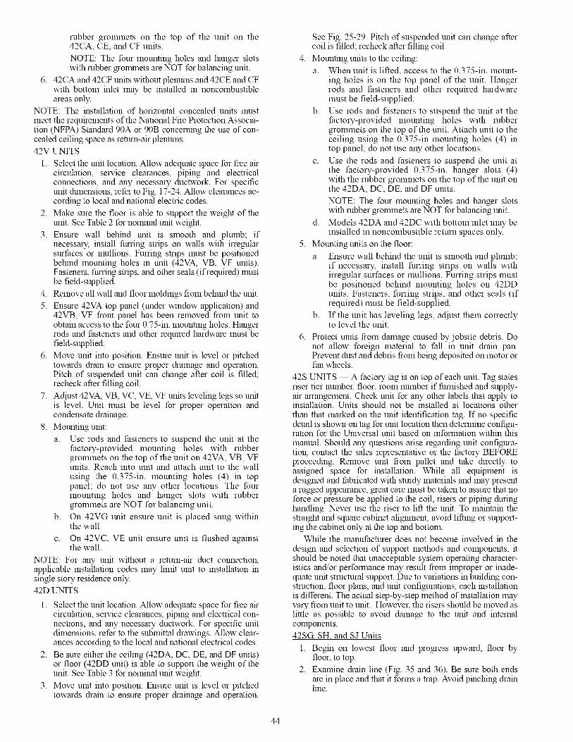
rubbergrolmnetsonthetopof theunit on the42CA,CE,andCFunits.NOTE:ThefourmountingholesandhangerslotswithrubbergrolrnnetsareNOTforbalancingunit.
6. 42CAand42CFunitswithoutplenumsand42CEandCFwithbottominletmaybeinstalledin noncombustibleareasonly.
NOTE:Theinstallationof horizontalconcealedunitsmustmeettherequirementsoftheNationalFireProtectionAssocia-tion(NFPA)Standard90Aor90Bconcerningtheuseofcon-cealedceilingspaceasreturn-airplenums.42VUNITS
1. Selecttheunitlocation.Allowadequatespaceforfleeaircirculation,serviceclearances,pipingandelectricalconnections,andanynecessaryductwork.Forspecificunitdhnensions,refertoFig.17-24.Allowclearancesac-cordingtolocalandnationalelectriccodes.
2. Makesurethefloorisabletosupporttheweightoftheunit.SeeTable2fornominalunitweight.
3. Ensurewall behindunit is smoothandplumb;ifnecessary,installfumngstripsonwallswithirregularsurfacesormullions.Fumngstripsmustbepositionedbehindmountingholesinunit(42VA,VB,VFunits).Fasteners,fumngstrips,andotherseals(ifrequired)mustbefield-supplied.
4. Removeallwallandfloormoldingsfrombehindtheunit.5. Ensure42VAtoppanel(underwindowapplication)and
42VB,VF frontpanelhasbeenremovedfromunittoobtainaccesstothefour0.75-in.mountingholes.Hangerrodsandfastenersandotherrequiredhardwaremustbefield-supplied.
6. Moveunitintoposition.Ensureunitis levelorpitchedtowardsdrainto ensureproperdrainageandoperation.Pitchof suspendedunitcanchangeaftercoilis filled;recheckafterfillingcoil.
7. Adjust42VA,VB,VC,VE,VFunitslevelinglegssounitis level.Unitmustbelevelforproperoperationandcondensatedrainage.
8. Mountingunit:a. Userodsandfastenersto suspendtheunitatthe
factory-providedmountingholeswith rubbergrommetsonthetopoftheuniton42VA,VB,VFunits.Reachintounitandattachunitto thewallusingthe0.375-in.mountingholes(4) in toppanel;donotuseanyotherlocations.Thefourmountingholesandhangerslotswith rubbergrommetsareNOTforbalancingunit.
b. On42VGunitensureunitisplacedsnugwithinthewall.
c. On42VC,VEunitensureunitis flushedagainstthewall.
NOTE:Foranyunitwithoutareturn-airductconnection,applicableinstallationcodesmaylimitunitto installationmsinglestoryresidenceonly.42DUNITS
1. Selecttheunitlocation.Allowadequatespaceforfleeaircirculation,serviceclearances,pipingandelectricalcon-nections,andanynecessaryductwork.Forspecificunitdimensions,refertothesubmittaldrawings.Allowclear-ancesaccordingtothelocalandnationalelectricalcodes.
2. Besureeithertheceiling(42DA,DC,DE,andDFunits)orfloor(42DDunit)isabletosupporttheweightoftheunit.SeeTable3fornominalunitweight.
3. Moveunitintoposition.Ensureunitis levelorpitchedtowardsdrainto ensureproperdrainageandoperation.
SeeFig.25-29.Pitchofsuspendedunitcanchangeaftercoilisfilled;recheckafterfillingcoil.
4. Mountingunitstotheceiling:a. Whenunitislifted,accesstothe0.375-in.mount-
ingholesis onthetoppanelof theunit.Hangerrodsandfastenersandotherrequiredhardwaremustbefield-supplied.
b. Userodsandfastenerstosuspendtheunitatthefactory-providedmountingholeswith rubbergrommetsonthetopoftheunit.Attachunittotheceilingusingthe0.375-inmountingholes(4) intoppanel;donotuseanyotherlocations.
c. Usetherodsandfastenerstosuspendtheunitatthefactory-provided0.375-in.hangerslots(4)withtherubbergrommetsonthetopoftheunitonthe42DA,DC,DE,andDFunits.NOTE:ThefourmountingholesandhangerslotswithrubbergrolmnetsareNOTforbalancingunit.
d. Models42DAand42DCwithbottominletmaybeinstalledinnoncombustiblereturnspacesonly.
5. Mountingunitsonthefloor:a. Ensurewallbehindtheunitissmoothandplumb;
if necessary,installfurringstripsonwallswithirregularsurfacesormullions.Fumngstripsmustbepositionedbehindmountingholeson42DDunits.Fasteners,furringstrips,andotherseals(ifrequired)mustbefield-supplied.
b. If theunithaslevelinglegs,adjustthemcorrectlytoleveltheunit.
6. Protect units froln damage caused by jobsite debris. Donot allow foreign material to fall in unit drain pan.Prevent dust and debris from being deposited on motor orfan wheels.
42S UNITS -- A factory tag is on top of each unit. Tag statesriser tier number, toot room number if furnished and supply-air arrangement. Check unit for any other labels that apply toinstallation. Units should not be installed at locations other
than that marked on the unit identification tag. If no specificdetail is shown on tag for unit location then determine configu-ration for the Universal unit based on information within this
manual. Should any questions arise regarding unit configura-tion, contact the sales representative or the factory BEFOREproceeding. Remove unit from pallet and take directly toassigned space for installation. While all equipment isdesigned and fabricated with sturdy materials and may presenta rugged appearance, great care must be taken to assure that noforce or pressure be applied to the coil, risers or piping duringhandling. Never use the riser to lift the unit. To maintain thestraight and square cabinet aligmnent, avoid lifting or support-ing the cabinet only at the top and bottom.
While the manufacturer does not become involved m the
design and selection of support methods and components, itshould be noted that unacceptable system operating character-istics and/or performance may result from improper or inade-quate unit structural support. Due to variations m building con-struction, floor plans, and unit configurations, each installationis different. The actual step-by-step method of installation mayvary from unit to unit. However, the risers should be moved aslittle as possible to avoid damage to the unit and internalcomponents.
42SG, SH and SJ Units
1. Begin on lowest floor and progress upward, floor byfloor, to top.
2. Examine drain line (Fig. 35 and 36). Be sure both endsare in place and that it forms a trap. Avoid pinching dramline.
44

3. Tip unit over riser hole in building floor. As unit isrighted, align riser with unit below.
NOTE: The unit must be lowered into the space takingcare to properly align the risers to engage the riser swagedsection on the unit below. The riser should never be bent
or pushed together to be passed through the floor slot andshould never be lifted up or pulled down to meet the riseron the floor below or above.
4. Install isolator pads beneath the four corners of unit ifapplicable.
5. Before anchoring the equipment in place, the unit must beleveled and the cabinet must be squared and brought intoline with any adjacent or included walls. The unit may beanchored in place by bolting directly through the unitfloor or attaching to the cabinet in some location that willnot interfere with drywall or other items such as the sup-ply grille, thermostat, or return access panel. When at-taching to the unit cabinet, care must be taken to not pen-etrate the cabinet in locations that may damage internalcomponents or wiring. The mounting technique is a mat-ter of choice; however, the unit should always be an-chored securely to prevent movement during constructionand riser expansion and contraction. On certain units,shipping screws or braces must be removed after the unitis installed. Be sure to check all tags on the unit to deter-mine which, if any, of these devices need to be removed.
6. If installing a 42SJ unit, follow Steps a-h. For 42SG and42SH units, continue to Step 7.NOTE: The 42SJ back-to-back fan coils have been de-
signed to serve two separate rooms. These products areclassified by Underwriters Laboratories Inc. for use inpenetration firestop systems, control number 27WL whenordered with 1-hr rated chase. See UL Fire Resistance
Directory for more information. Figure 40 shows the42SJ unit with standard risers and with Siamese risers.
a. Lay out the control lines for the drywall track andstuds in the floor and ceiling (see Fig. 41).
42SJA
42SJB
42SJA f
42SJB
Fig. 40 -- 42SJUnit with Standard and Siamese Risers
E 1
CHASESIDEPANEL
\\
DRYWALLTRACK ANDSTUDCONTROLLINES
D D ,NSTALLWALLSTUDINTOPOCKETFORMEDBYCHASE SIDE
L!i"i _ PANEL
INSTALL STUDS FROM TOP OFUNIT TO CEILING (4 CORNERS)
Fig. 41 -- 42SJ Wall Board Installation
b.
NOTE: Tracking may be installed now or after theunit is set.
Position the 42SJ fan coil assembly between tworooms with the unit drywall separation spottedover the wall control lines.
c. If not already installed, install the floor and ceilingtracks up to and over the 42SJ fan coil unit.
d. Position the vertical studs and fasten into each of
the stud pockets formed into the chase side panels(see Fig. 41).
NOTE: The studs may be mechanically fastenedto the 42SJ fan coil. Care should be taken, how-ever, not to penetrate the supply or return waterrisers or internal piping. Given the levelness of thefloor and/or the fan coil assembly, some shimmingmay be necessary.
e. Assemble the specified wall construction up toand over the top of the fan coil unit (see Fig. 42).
L IINSTALL WALLGYPSUM
WALL STUDS BOARD
(TO WALL ANDOVER TOP OFUNIT)
ldHHHHHHHHH _ ,'_ _ ............... ;_ _,_Z _HHHH_
D [qJ ,NSTALL
GYPSUMINSTALL BOARD TOGYPSUM UNIT SIDES
BOARD TO [3 NFACE OF =
UNIT WITHCUT OUTS
FOR SUPPLY, ]RETURN AND
THERMOSTAT --
Fig. 42 -- 42SJ Unit Installation
f. With the fire-wall separation being complete, thedrywall skin on the surface of the individual fancoils can be applied. Drywall can be applieddirectly to the surface, oc if necessary, studdingmay be installed on the corners for vertical control(see Fig. 42).
g. For ease of installation of the access panel, applydrywall on the return air side directly to the sur-face of the unit (see Fig. 42). When applying thewall board directly to the unit cabinet, it may benecessary to shim the wall board in some areas toachieve the desired finished wall surface.
h. After all drywalling and painting is complete,install thermostats, supply air grilles and return airpanels.
7. Attach unit risers:
Toxic residues and loose particles resulting froln lnanufac-raring and field piping techniques such as joint compounds,soldering flux, and metal shavings may be present in theunit and the piping system. Special consideration must begiven to system cleanliness when connecting to solar,domestic or potable water systems. Failure to heed thiswarning could result in equipment damage.
45
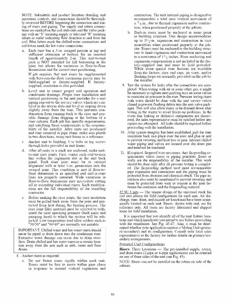
NOTE: Submittals and product literature detailing unitoperation, controls, and connections should be thorough-ly reviewed BEFORE beginning the connection and test-ing of risers and piping. The supply and return connec-tions are marked on the coil stub-outs and the valve pack-age with an"S" meaning supply or inlet and "R" meaningreturn or outlet indicating flow direction to and from thecoil. Blue letters mark the chilled water connections andred letters mark the hot water connections.
a. Each riser has a 3-in. swaged portion at top andsufficient extension at bottom for an inserted
length of approximately 2-in. This unit-to-unitjoint is NOT intended for full bottoming in thejoint, but allows for variations in floor-to-floordimensions and for correct riser positioning.
If job requires that unit risers be supplementedwith between-the-floor extensions pieces may befield-supplied or factory-supplied. If factory-supplied, insulation is also provided.
b. Level unit to ensure proper coil operation andcondensate drainage. Proper riser installation andvertical positioning in the unit provides for a unitpiping run-out to the service valves which are cen-tered in the access slots and level or sloping downslightly away from the riser. This prevents con-densation from running back to the riser and pos-sible damage from dripping at the bottom of ariser column. Each job has specific requirements,and satisfying those requirements is the responsi-bility of the installer. After units are positionedand riser centered in pipe chase, make unit plumbin two directions, using unit frame as a reference.
c. Anchor unit to building. Use bolts or lag screwsthrough holes provided in unit frame.
d. After all units in a stack are anchored, make unit-to-unit riser joints. First, center each coil-to-riserline within the expansion slot in the unit backpanel. Each riser joint must be in verticalaligmnent with at least 1-in. penetration into theswaged joint. This condition is met if floor-to-floor dimension is as specified and coil-to-riserlines are properly centered. Wide variations infloor-to-floor dimensions may necessitate cuttingoff or extending individual risers. Such modifica-tions are the full responsibility of the installingcontractor.
e. Before making the riser joints, the riser insulationmust be pulled back away from the joint and pro-tected from heat during the brazing process. Theriser joint filler material must be selected to with-stand the total operating pressure (both static andpumping head) to which the system will be sub-jected. Low temperature lead alloy solders such as"50/50" and "60/40" are normally not suitable.
IMPORTANT: Chilled water and hot water risers shouldnever be piped to dram down into the condensate riser.Extensive water damage can occur due to dram over-flow. Drain chilled and hot water risers to a remote loca-tion away from the unit such as sink, room and floordrams.
8. Anchor risers as required:
a. Do not fasten risers rigidly within each unit.Risers must be free to move within pipe chasein response to normal vertical expansion and
b.
contraction. The unit internal piping is designed toaccommodate a total riser vertical movement of
4- 3/4 in., due to thermal expansion and/or contrac-
tion, when positioned properly at the jobsite.
Built-in risers must be anchored at some pointto building structure. Unit design accolmnodatesup to l l/2-in, expansion and contraction in riser
assemblies when positioned properly at the job-site. Risers must be anchored to the building struc-ture to limit expansion and contraction movementto a maximum of 11/2 inches. Riser anchoring and
expansion compensation is not included in the fac-tory-supplied unit and must be field provided.While some special riser features are availablefrom the factory, riser end caps, air vents, and/orflushing loops are normally provided on the job bythe installer.
9. Test the system for leaks after the connections are coin-pleted. When testing with air or some other gas, it mightbe necessary !o tighten stein packing nuts on some valvesto mmntmn air pressure in the riser. Pressure testing riserswith water should be done with the unit service valves
closed to prevent flushing debris into the unit valve pack-ages. This will also allow risers to be drained down aftertesting in the winter to avoid freeze-up problems. In theevent that leaking or defective components are discov-ered, the sales representative must be notified before anyrepairs are attempted. All leaks should be repaired beforeproceeding with the installation.
10. After system integrity has been established, pull the riserinsulation back into place over the joint and glue or sealto prevent sweating and heat loss or gain. Internal chilledwater piping and valves are located over the dram panand need not be insulated.
11. If required, fireproof were necessary. Any fireproofing re-quirements where risers or piping penetrate floors orwalls are the responsibility of the installer. This workshould be done only after all pressure testing is complet-ed. The fireproofing method used must accolr_nodatepipe expansion and contraction and the piping must beprotected from abrasion and chemical attack. The pipe in-sulation also must be maintained to prevent sweating andmust be protected from wear or erosion at the joint be-tween the insulation and the fireproofing material.
42 SU Units -- The unique design of the universal stack fancoil unit allows for field configuration for each unit. Air dis-charge, riser, drain, and outside air knockouts have been strate-gically located on each unit. Risers, shown with unit, are forreference only. All risers are factory fabricated and shippedloose for field installation.
It is important that you identify all of the unit feature loca-tions and which knockouts you intend to use before proceedingwith the installation. See Fig. 45-47. Also, it must be deter-mined whether your application requires a Mating Unit (prima-ry/secondary) and its configuration. Consult your local salesrepresentative or the factory for further details on prhnary/sec-ondary arrangements.
Potential Unit Configurations
Risers: Three Locations -- The pre-installed supply, return,and drain risers (2-pipe or 4-pipe applications) can be orientedon any of three sides of the unit (see Fig. 43).NOTE: Risers can not be installed on the return air side of thecabinet.
46
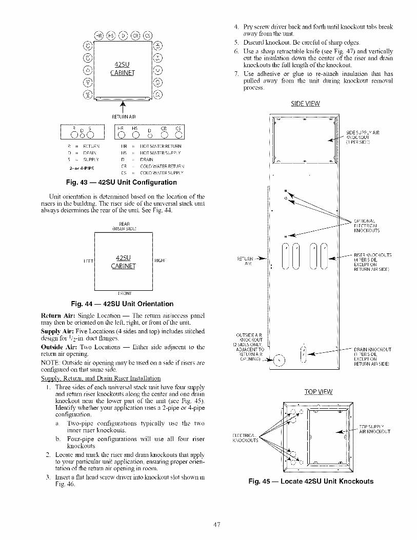
@@©@@©@©©®
42SU
CABINET
I'RETURN AIR
r®®©©©
HR HS CR 8o o oR = RETURN HR HOT WATER RETURN
D = DRAIN HS HOTWATERSUPPLY
S = SUPPLY D DRAIN
2- or &PIPE CR COLD WATER RETURNCS COLD WATER SUPPLY
Fig. 43 -- 42SU Unit Configuration
Unit orientation is determined based on the location of the
risers m the building. The riser side of the universal stack unitalways determines the rear of the unit. See Fig. 44.
REAR
(RISER SIDE)
LEFT42SU
CABINETRIGHT
FRONT
Fig. 44 -- 42SU Unit Orientation
Return Air: Single Location -- The return air/access panelmay then be oriented on the left, right, or front of the unit.
Supply Air: Five Locations (4 sides and top) includes stitcheddesign for 1/2-in. duct flanges.
Outside Air: Two Locations -- Either side adjacent to thereturn air opening.
NOTE: Outside air opening may be used on a side if risers areconfigured on that same side.
Supply, Return and Drain Riser Installation
1. Three sides of each universal stack unit have four supplyand return riser knockouts along the center and one drainknockout near the lower part of the unit (see Fig. 45).Identify whether your application uses a 2-pipe or 4-pipeconfiguration.
a. Two-pipe configurations typically use the twoinner riser knockouts.
b. Four-pipe configurations will use all four riserknockouts.
2. Locate and mark the riser and dram knockouts that applyto your particular unit application, ensuring proper orien-tation of the return air opening in room.
3. Insert a flat head screw driver into knockout slot shown in
Fig. 46.
4. Pry screw driver back and forth until knockout tabs breakaway from the unit.
5. Discard knockout. Be careful of sharp edges.
6. Use a sharp retractable knife (see Fig. 47) and verticallycut the insulation down the center of the riser and drainknockouts the full length of the knockout.
7. Use adhesive or glue to re-attach insulation that haspulled away from the unit during knockout removalprocess.
SIDEVIEW
RETURN -_AIR
OUTSIDE AIRKNOCKOUT
(2 SIDES ONLY,ADJACENT TO
RETURN AIR
OPENING)
SIDE SUPPLY AIR/ KNOCKOUT
_'_ (1 PERSIDE)
_ PTIONALELECTRICALKNOCKOUTS
OO@@- (4 PER SIDE,EXCEPTONRETURN AIR SIDE)
@ _-iDRA,NKNOCKOUT(1 PER SIDE,_, _ EXCEPTON
/ RETURN AIR SIDE)
TOP VIEW
O O ] _- :,5_--
ELECTRICAL _ II_
Fig. 45 -- Locate 42SU Unit Knockouts
TOP SUPPLYAIR KNOCKOUT
47
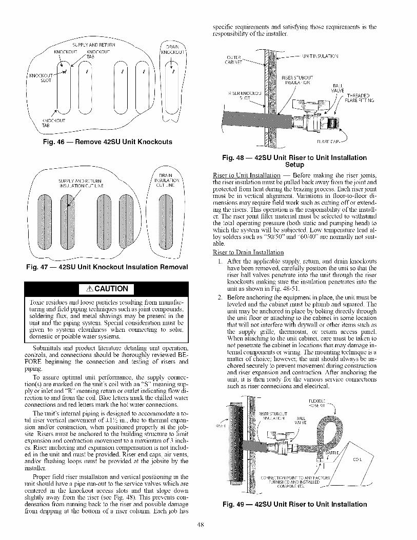
DRAIN(NOCKO!
g
Fig. 46 -- Remove 42SU Unit Knockouts
specific requirements and satisfying those requirements is theresponsibility of the installer.
OUTER UNIT INSULATION
RISER STUBOUTINSULATION
BALLVALVE
RISER KNOCKOU THREADEDSLOT FLARE FITTING
FLARE CAP _
SUPPLY AND RETURNINSULATION CUT LINE
Fig. 47 -- 42SU Unit Knockout Insulation Removal
Toxic residues and loose particles resulting from manufac-turing and field piping techniques such as joint compounds,soldering flux, and metal shavings may be present in theunit and the piping system. Special consideration must begiven to system cleanliness when connecting to solar,domestic or potable water systems.
Submittals and product literature detailing unit operation,controls, and connections should be thoroughly reviewed BE-FORE beginning the connection and testing of risers andpiping.
To assure optimal unit performance, the supply connec-tion(s) are marked on the unit's coil with an '%" meaning sup-ply or inlet and "R" meaning return or outlet indicating flow di-rection to and from the coil. Blue letters mark the chilled waterconnections and red letters mark the hot water connections.
The unit's internal piping is designed to accommodate a to-tal riser vertical movement of-q½ in., due to thermal expan-sion and/or contraction, when positioned properly at the job-site. Risers must be anchored to the building structure to limitexpansion and contraction movement to a maxilnum of 3 inch-es. Riser anchoring and expansion compensation is not includ-ed in the unit and must be provided. Riser end caps, air vents,and/or flushing loops must be provided at the jobsite by theinstaller.
Proper field riser installation and vertical positioning in theunit should have a pipe run-out to the service valves which arecentered in the knockout access slots and that slope downslightly away from the riser (see Fig. 48). This prevents con-densation from running back to the riser and possible damagefrom dripping at the bottom of a riser column. Each job has
Fig. 48- 42SU Unit Riser to Unit InstallationSetup
Riser to Unit Installation -- Before making the riser joints,the riser insulation must be pulled back away from the joint andprotected from heat during the brazing process. Each riser jointmust be in vertical alignment. Variations in floor-to-floor di-mensions may require field work such as cutting offor extend-ing the risers. This operation is the responsibility of the install-er. The riser joint filler material must be selected to withstandthe total operating pressure (both static and pumping head) towhich the system will be subjected. Low temperature lead al-loy solders such as "50/50" and "60/40" are normally not suit-able.
Riser to Drain Installation
1.
2.
After the applicable supply, return, and drain knockoutshave been removed, carefully position the unit so that theriser ball valves penetrate into the unit through the riserknockouts making sure the insulation penetrates into theunit as shown in Fig. 48-51.
Before anchoring the equipment in place, the unit must beleveled and the cabinet must be plumb and squared. Theunit may be anchored in place by bolting directly throughthe unit floor or attaching to the cabinet in some locationthat will not interfere with drywall or other items such asthe supply grille, thermostat, or return access panel.When attaching to the unit cabinet, care must be taken tonot penetrate the cabinet in locations that may damage in-ternal components or wiring. The mounting technique is amatter of choice; however, the unit should always be an-chored securely to prevent movement during constructionand riser expansion and contraction. After anchoring theunit, it is then ready for the various service connectionssuch as riser connections and electrical.
RISERSTUBOUT
FLEXIBLE
HOSE KIT -_
RISER
BALLVALVE
COMPONENTS.
Fig. 49- 42SU Unit Riser to Unit Installation
48
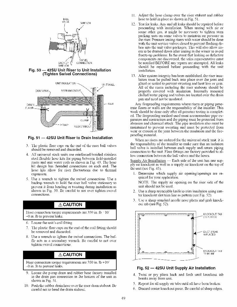
BALL
VALVE WRENCH
L
SWIVELBACK-UP CONNECTIONWRENCH
Fig. 50 -- 42SU Unit Riser to Unit Installation(Tighten Swivel Connections)
UNIT INSULATION_
RISER KNOCKOUT\
UNITWALL
RISER
P-TRAP
Fig. 51 -- 42SU Unit Riser to Drain Installation
3.
4.
5.
The plastic flare caps on the end of the riser ball valvesshould be removed and discarded.
All universal stack units use remforced braided stainless
steel flexible hose kits for piping between field-installedrisers and unit water coils as shown m Fig. 49. The hosekit design has threaded connections on each end. Thehose kits allow for riser fluctuations due to thermalexpansion.
Use a wrench to tighten the swivel connections. Use abackup wrench to hold the riser ball valve stationary toprevent it from bending or twisting durmg installation asshown m Fig. 50. Be careful to not over tighten swivelconnections.
Hose connection torque requirements are 350 in. lb +10/-0 in. lb to prevent leaks.
6. Locate the unit's coil fittmg.
7. The plastic flare caps on the end of the coil fitting shouldbe removed and discarded.
8. Use a wrench to tighten the swivel connections. The baf-fle acts as a secondary wrench. Be careful to not overtighten swivel connections.
Hose connection torque requirements are 350 in. lb +10/-0 in. lb to prevent leaks.
9. Locate the p-trap drain and rubber hose factory installedto the dram pan connection in the bottom of the unit asshown m Fig. 51.
10. Push the rubber drain hose over the riser drain smbout. Becareful not to bend the drain smbout.
11.
12.
Adjust the hose clamp over the riser smbout and rubberhose to hold in place as shown in Fig. 51.
Test for leaks. Any and all leaks should be repaired beforeproceeding with installation. When testing with air orsome other gas, it might be necessary to tighten stempacking nuts on some valves to maintain air pressure inthe riser. Pressure testing risers with water should be donewith the unit service valves closed to prevent flushing de-bris into the unit valve packages. This will also allow ris-ers to be drained down after testing in the winter to avoidfreeze-up problems. In the event that leaking or defectivecomponents are discovered, the sales representative mustbe notified BEFORE any repairs are attempted. All leaksshould be repaired before proceeding with the unitinstallation.
13. After system integrity has been established, the riser insu-lation must be pulled back into place over the joint andglued or sealed to prevent sweating and heat loss or gam.All of the risers including the riser stubouts should beproperly covered with insulation. Internally mountedchilled water piping and valves are located over the drainpan and need not be insulated.
Any fireproofing requirements where risers or piping pene-trate floors or walls are the responsibility of the installer. Thiswork should be done only after all pressure testing is complet-ed. The fireproofing method used must accolmnodate pipe ex-pansion and contraction and the piping must be protected fromabrasion and chemical attack. The pipe msulation also must bemaintained to prevent sweatmg and must be protected fromwear or erosion at the joint between the insulation and the fire-proofing material.
When no risers are ordered for the universal stack unit, it isthe responsibility of the mstaller to make sure that an isolationball valve is mstalled between each supply and return pipingconnection to the unit. Flare fittings are factory provided to al-low connection between the ball valves and the hoses.
Supply Air Installation -- Each side of the unit has one sup-ply air knockout as well as a supply air knockout on the top ofthe unit (see Fig. 45).
1. Determine which supply air opening/openings are re-quired for your application.
NOTE: The supply air opening on the riser side of theunit should not be used.
2. Use a sharp retractable knife to trim insulation using cen-ter knockout slot/trim lme as pattern (see Fig. 52).
3. Use a sharp standard needle nose pliers and grab knock-out tab (see Fig. 52).
KNOCKOUT TAB_/(IOPLACES)
DUCT BREAK(4 PLACES)
KNOCKOUT TABTRIM LINE
Fig. 52 -- 42SU Unit Supply Air Installation
4. Twist or pry pliers back and forth until knockout tabbreaks away from unit.
5. Repeat for all supply air tabs until all have been broken.
6. Discard center knockout piece. Be careful of sharp edges.
49

7. Useasharpretractableknifetotrilnanyexcessinsulationusingknockoutholeaspattern.
8. Useductpliers(handseamers)tofoldductflangeoutoftheunit90degreesforeachsideofthesupplyairopeningalongductbreak(seeFig.52).The90-degreeflangescannowbeusedasdrywallstopstopreventcoverageofdis-chargeopening(seeFig.53).
9. Useadhesiveor glueto re-attachinsulationthathaspulledawayfromtheunitduringknockoutremovalprocess.
10.Forductedapplicationstapeshouldbeappliedalongandaroundallofthesupplyairopeningknockoutstopreventairleakage.
Duc ze
tUNIT
INSULATION
Fig. 53 -- 42SU Supply Air Installation
All installations should be made in compliance with all gov-erning codes and ordinances. Compliance with all codes is theresponsibility of the installing contractor.
42 SM Units -- The unique design of the mega stack fan coilunit allows for field configuration of each unit. Risers, shownwith unit, are for reference only. All risers are factory fabricat-ed and shipped loose for field installation.
It is important that you identify all of the unit feature loca-tions before proceeding with the installation. Also, it must bedetermined whether your application requires a mating unit(primary/secondary) and its configurations. Consult your localsales representative or the factory for further details on prima-ry/secondary arrangelnents.
Unit orientation is determined based on the location of the
risers in the building. Risers can only be installed on the rearside of the unit and it always determines the rear of the megastack unit. The return air is always on the front (see Fig. 54).
LEFT
@G@@@
REAR I
42SMCABINET RIGHT
FRONT
RETURN AIR
Supply. Return. and Drain Risers
Toxic residues and loose particles resulting froln lnanufac-raring and field piping techniques such as joint compounds,soldering flux, and metal shavings may be present in theunit and the piping system. Special consideration must begiven to system cleanliness when connecting to solar,domestic or potable water systems.
Submittals and product literature detailing unit operation,controls, and connections should be thoroughly reviewed BE-FORE beginning the connection and testing of risers andpiping.
The supply and return connections are marked on the coilstub.outs and the valve package depending on your configura-tion. "CS" means cold water supply, "CR" means cold waterreturn, "HS" means hot water supply, and "HR" means hot wa-ter return to indicate flow direction to and from the coil. Blueletters mark the chilled water connections and red letters markthe hot water connections.
The unit internal piping is designed to accommodate a totalriser vertical movement of+l 1/2 m., due to thermal expansionand/or contraction, when positioned properly at the jobsite.Risers must be anchored to the building structure to limit riserexpansion and contraction movement to a lnaxilnum of 3 inch-es. Riser anchoring and expansion compensation is not includ-ed in the factory-supplied unit and must be field provided.While some special riser features are available from the factory,riser end caps, air vents, and/or flushing loops are normallyprovided on the job by the installer.
Riser to Unit Installation -- Proper riser installation and verti-cal positioning in the unit provides for a unit piping ran-out tothe service valves which are centered in the access slots and
level or sloping down slightly away from the riser. This pre-vents condensation from running back to the riser and possibledamage from dripping at the bottom of a riser column. Eachjob has specific requirements and satisfying those requirementsis the responsibility of the installer.
Riser to Drain Installation
1. Carefully position the unit so that the riser ball valvespenetrate into the unit through the riser slot making surethe insulation penetrates into the unit as shown in Fig. 55and 56.
OUTER UNIT INSULATION
RISER STUBOUTINSULATION
BALLVALVE
THREADEDFITTING
HR HS CR CS }o o o oR = RETURN HA = HOT WATER RETURN
D = DRAIN HS = HOTWATERSUPPLY
S = SUPPLY D = DRAIN
2-or4-PIPE CR = COLD WATER RETURNCS = COLD WATER SUPPLY
Fig. 54 -- 42SM Unit Installation
FLARECAI
Fig. 55 -- 42SM Riser to Unit Installation
5O

RISER
RISER STUBOUTBALL
VALVE
COMPONENTS.
FLEXIBLE
HOSE KIT
COIL
2.
3.
4.
5.
Fig. 56 -- 42SM Riser to Unit Installation
Before anchoring the equipment in place, the unit must beleveled and the cabinet must be plumb and squared. Theunit may be anchored in place by bolting directly throughthe unit's floor or attaching to the buildings walls throughthe cabinet walls in some location that will not interferewith drywall or other items such as the supply grille, ther-mostat, or return access panel. When attaching sheetrockto the unit cabinet, care must be taken to not penetrate thecabinet in locations that may damage internal compo-nents or wiring. The mounting technique is a matter ofchoice; however, the unit should always be anchored se-curely to the building to prevent movement during con-struction and riser expansion and contraction. After an-choring the unit, it is then ready for the various serviceconnections such as riser connections and electrical.
The plastic flare caps on the end of the riser ball valvesshould be removed and discarded.
All mega stack units use reinforced braided stainless steelflexible hose kits for piping between field installed risersand unit water coils as shown in Fig. 56. Each hose hasthreaded connections on each end. The hose kits allow for
riser fluctuations due to thermal expansion.
Use a wrench to tighten the swivel connections. Use abackup wrench to hold the riser ball valve stationary toprevent it from bending or twisting during installation asshown m Fig. 57. Be careful to not over tighten swivelconnections.
BALL
VALVE WRENCH
SWIVEL
BACK-UP CONNECTIONWRENCH
Fig. 57 -- 42SM Riser to Unit Installation(Tighten Swivel Connections)
Hose connection torque requirements are 350 in. lb +10/-0 in. lb to prevent leaks.
6. Locate the unit's coil fitting.
7.
8.
The plastic flare caps on the end of the coil fitting shouldbe removed and discarded.
Use a wrench to tighten the swivel connections. The baf-fle acts as a secondary wrench. Be careful to not overtighten swivel connections.
Hose connection torque requirements are 350 in. lb +10/-0 m. lb to prevent leaks.
9. Locate the p-trap dram and rubber hose factory installedto the drain pan connection in the bottom of the unit asshown in Fig. 58.
10. Push the rubber drain hose over the riser drain smbout. Be
careful that you do not bend the dram smbout.
11. Adjust the hose clamp over the riser smbout and rubberhose to hold in place as shown in Fig. 58.
DRAIN PAN\
UNIT WALL
f
P-TRAP
12.
13.
Fig. 58 -- 42SM Riser to Drain Installation
Test for leaks. Any and all leaks should be repaired beforeproceeding with installation. When testing with air orsome other gas, it might be necessary to tighten steinpacking nuts on some valves to maintain air pressure inthe riser. Pressure testing risers with water should be donewith the unit service valves closed to prevent flushing de-bris into the unit valve packages. These valves will alsoallow risers to be drained down after testing m the winterto avoid freeze-up problems. In the event that leaking ordefective components are discovered, the sales represen-tative must be notified BEFORE any repairs are attempt-ed. All leaks should be repaired before proceeding withthe unit installation.
After system integrity has been established, the riser insu-lation must be pulled back into place over the joint andglued or sealed to prevent sweating and heat loss or gain.All of the risers including the riser stubouts should beproperly covered with insulation. Internally mountedchilled water piping and valves are located over the drainpan and need not be insulated.
Any fireproofing requirements where risers or pipingpenetrate floors or walls are the responsibility of the in-staller. This work should be done only after all pressuretesting is completed. The fireproofing method used mustaccolmnodate pipe expansion and contraction and thepiping must be protected from abrasion and chemical at-tack. The pipe insulation also must be maintained to pre-vent sweating and must be protected from wear or ero-sion at the joint between the insulation and the fireproof-ing material.
When no risers are ordered for the mega stack unit, it isthe responsibility of the installer to make sure that a field-supplied isolation ball valve is installed between eachsupply and return piping connection to the unit. Flare fit-
51

tingsarefactoryprovidedto allowconnectionbetweenthe ball valves and the hoses.
Variations in floo>to-floor dhnensions may require fieldwork such as cutting off or extending the risers. This op-eration is the responsibility of the installer. The riser jointfiller material must be selected to withstand the total op-erating pressure (both static and pumping head) to whichthe system will be subjected. Low temperature lead alloysolders such as "50/50" and "60/40" are normally notsuitable.
Chilled water and hot water risers should never be pipedto dram down into the condensate riser. Extensive water
damage can occur due to drain overflow. Drain chilledand hot water risers to a remote location away from theunit such as sink, room and floor drams.
All installations should be made in compliance with allgoverning codes and ordinances. Compliance with allcodes is the responsibility of the installing contractor.
Supply Air Installation
1. If the unit has been ordered with a supply air plenum,then each side of the unit has one supply air knockout aswell as a supply air knockout on the top of the unit (seeFig. 59 and 60).
2. Determine which supply air opening/openings are re-quired for your application.
NOTE: The supply air opening on the riser side of theunit should not be used.
3. Use a sharp retractable knife to trim insulation using cen-ter knockout slot!trim line as pattern (see Fig. 61).
4. Use a sharp standard needle nose pliers and grab knock-out tab (see Fig. 61).
5. Twist or pry pliers back and forth until knockout tabbreaks away from unit.
6. Repeat for all supply air tabs until all have been broken.
7. Discard center knockout piece. Be careful of sharp edges.
8. Use a sharp retractable knife to trim any excess insulationusing knockout hole as pattern.
9. Use duct pliers (hand seamers) to fold duct flange out ofthe unit 90 degrees for each side of the supply air openingalong duct break (see Fig. 61). The 90-degree flanges cannow be used as drywall stops to prevent coverage of dis-charge opening (see Fig. 62).
SIDEVIEW
SIDE SUPPLY AIRKNOCKOUT --(1 PER SIDE)
OPTIONALSUPPLYPLENUM
MEGA MODCABINET
_J
Fig. 59 -- 42SM Unit Knockout LocationsSide View (Typical)
TOP VIEW
ELECTRICAL_
KNOCKOUTS "_
__ TOP SUPPLYAIR KNOCKOUT
Fig. 60 -- 42SM Unit Knockout LocationsTop View (Typical)
mR mR mR
I KNOCKOUT TAB
/ (lO PLACES)
t / DUCT BREAK(4 PLACES)
KNOCKOUT TABTRIM LINE
./-
Fig. 61 -- 42SM Unit Supply Air Installation
:""_ DUCT FLANGE
UNIT
INSULATION
Fig. 62 -- 42SM Unit Supply Air Installation
10. Use adhesive or glue to re-attach insulation that haspulled away from the unit during knockout removalprocess.
11. For ducted applications tape should be applied along andaround all of the supply air opening knockouts to preventair leakage.
Step 2 -- Make Piping Connections -- Access topiping is available through the access panels at the side of theunits or front of the unit. Qualified personnel in accordancewith local and national codes must perform all piping connec-tions. Refer to Tables 1-4 for piping connections.
NOTE: It is important to have a colmnon understanding ofwhich side of the unit is the right hand side and which is theleft hand side.
When facing the supply air outlet from the front of the unit(air blowing in your face), your right hand will be on the rightside of the unit and your left hand will be on the left side of theunit. See Fig. 63. Refer to Fig. 64 and 65 for typical pipingconnections.
52
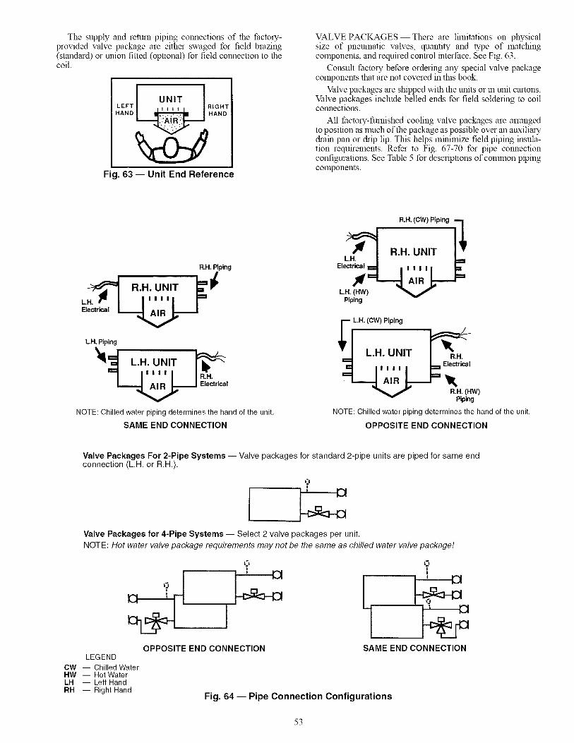
The supply and return piping connections of the factory-provided valve package are either swaged for field brazing(standard) or union fitted (optional) for field connection to thecoil.
I UNIT ILEFT RIGHT
HAND _ HAND
Fig. 63 -- Unit End Reference
VALVE PACKAGES- There are lhnitations on physicalsize of pneumatic valves, quantity and type of matchingcomponents, and required control interface. See Fig. 63.
Consult factory before ordering any special valve packagecomponents that are not covered in this book.
Valve packages are shipped with the units or m unit cartons.Valve packages include belled ends for field soldering to coilconnections.
All factory-furnished cooling valve packages are arrangedto position as much of the package as possible over an auxiliarydram pan or drip lip. This helps minimize field piping insula-tion requirements. Refer to Fig. 67-70 for pipe connectionconfigurations. See Table 5 for descriptions of connnon pipingcomponents.
R.H. Piping
LH. Piping
NOTE: Chilled water piping determines the hand of the unit,
SAME END CONNECTION
R.H. (CW) Piping "'1
Piping
-- L.H. (CW) Piping
Piping
NOTE: Chilled water piping determines the hand of the unit,
OPPOSITE END CONNECTION
Valve Packages For 2-Pipe Systems -- Valve packages for standard 2-pipe units are piped for same endconnection (L.H. or R.H.).
Valve Packages for 4-Pipe Systems -- Select 2 valve packages per unit.
NOTE: Hot water valve package requirements may not be the same as chilled water valve package!
LEGEND
CW -- Chilled WaterHW -- Hot WaterLH -- Left HandRH -- Right Hand
OPPOSITE END CONNECTION
15
SAME END CONNECTION
Fig. 64 -- Pipe Connection Configurations
53
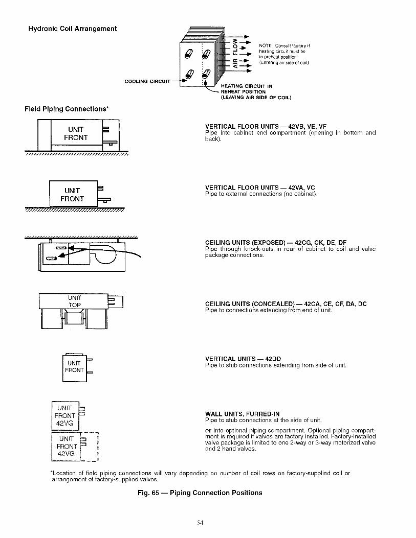
Hydronic Coil Arrangement
COOLING
Field Piping Connections*
UNIT =
FRONT
i i
i _ NOTE: Consult factory if
_1_ heating circuit must beu. _ in preheat position.n- _ (Entering air side of coil)
HEATING CIRCUIT INREHEAT POSITION
(LEAVING AIR SIDE OF COIL)
VERTICAL FLOOR UNITS -- 42VB, VE, VFPipe into cabinet end compartment (opening in bottom andback).
I UNITFRONT
_7/7/////7//////////////////////////_
VERTICAL FLOOR UNITS -- 42VA, VCPipe to external connections (no cabinet).
CEILING UNITS (EXPOSED)- 42CG, CK, DE, DFPipe through knock-outs in rear of cabinet to coil and valvepackage connections.
I UNITTOP CEILING UNITS (CONCEALED)- 42CA, CE, CF, DA, DCPipe to connections extending from end of unit.
VERTICAL UNITS -- 42DDPipe to stub connections extending from side of unit.
UNIT IFRONT42VG
]I||
.!
WALL UNITS, FURRED-INPipe to stub connections at the side of unit.
or into optional piping compartment. Optional piping compart-ment is required if valves are factory installed. Factory-installedvalve package is limited to one 2-way or 3-way motorized valveand 2 hand valves.
*Location of field piping connections will vary depending on number of coil rows on factory-supplied coil orarrangement of factory-supplied valves.
Fig. 65 -- Piping Connection Positions
54
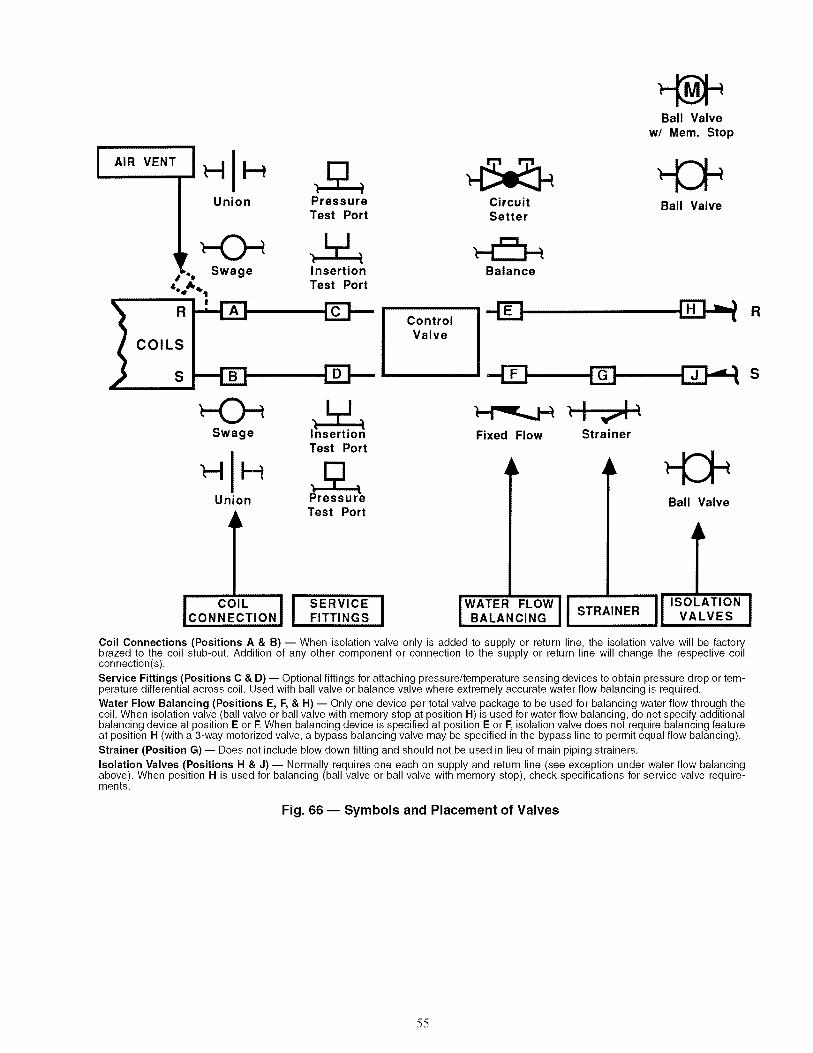
AIR VENT
I COILSS
Union PressureTest Port
CircuitSetter
Ball Valvew/ Mem. Stop
Ball Valve
=_,!_._ Swage
Swage
Union
l
I i
InsertionTest Port
ControlValve
Balance
- _ R
Test Port
Test Port
--4Z3, I I,
Fixed Flow Strainer
Ball Valve
I COIL I I SERVICE I IWATER FLOWII ISOLATIONCONNECTION FITTINGS , BALANCING STRAINER VALVES
Coil Connections (Positions A & B) -- When isolation valve only is added to supply or return line, the isolation valve will be factorybrazed to the coil stub-out, Addition of any other component or connection to the supply or return line will change the respective coilconnection(s),
Service Fittings (Positions C & D) -- Optional fittings for attaching pressure/temperature sensing devices to obtain pressure drop or tem-perature differential across coil, Used with ball valve or balance valve where extremely accurate water flow balancing is required,
Water Flow Balancing (Positions E, F, & H) -- Only one device per total valve package to be used for balancing water flow through thecoil, When isolation valve (ball valve or ball valve with memory stop at position H) is used for water flow balancing, do not specify additionalbalancing device at position E or E When balancing device is specified at position E or E isolation valve does not require balancing featureat position H (with a 3-way motorized valve, a bypass balancing valve may be specified in the bypass line to permit equal flow balancing),
Strainer (Position G) -- Does not include blow down fitting and should not be used in lieu of main piping strainers,
Isolation Valves (Positions H & J) -- Normally requires one each on supply and return line (see exception under water flow balancingabove), When position H is used for balancing (ball valve or ball valve with memory stop), check specifications for service valve require-ments,
Fig. 66 -- Symbols and Placement of Valves
55
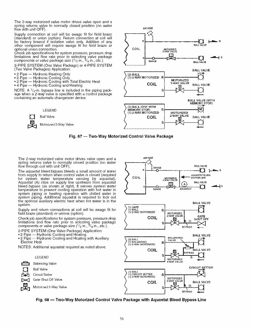
The 2-way motorized valve motor drives valve open and aspring returns valve to normally closed position (no waterflow with unit OFF).
Supply connection at coil will be swage fit for field braze(standard) or union (option). Return connection at coil willbe factory brazed if isolation valve only. Addition of anyother component will require swage fit for field braze oroptional union connection.Check job specifications for system pressure, pressure droplimitations and flow rate prior to selecting valve packagecomponents or valve package size (1/2 in.,_/4 in., etc.).
2-PIPE SYSTEM (One Valve Package) or 4-PIPE SYSTEM(Two Valve Packages) Application:
• 2 Pipe i Hydronic Heating Only• 2 Pipe i Hydronic Cooling Only• 2 Pipe i Hydronic Cooling with Total Electric Heat• 4 Pipe i Hydronic Cooling and Heating
NOTE: A 1/4-in. bypass line is included in the piping pack-age when a 2-way valve is specified with a control packagecontaining an automatic changeover device.
LEGEND
Ball Valve
Motorized 2-Way Valve
AiR VENT
BALL VALVE
MOTORIZED2-WAY VALVE
aSWAGE BALL VALVE
| R
BALL VALVE
2) BALL i(1) 2-WAY MOTORIZED R_ _ J
MOTORIZED _v
ALVE
BALL VALVE (WITH_A= MEMORY STOP)
(2) HALL (ONE With [MEMORY STOP) R I _._(1) 2-WAY MOTORIZED I MOTORIZED
LVE
Fig. 67 -- Two-Way Motorized Control Valve Package
The 2-way motorized valve motor drives valve open and aspring returns valve to normally closed position (no waterflow through coil with unit OFF).
The aquastat bleed bypass bleeds a small amount of waterfrom supply to return when control valve is closed (requiredfor system water temperature sensing by aquastat).Aquastat (A) clips on supply line upstream from aquastatbleed bypass (as shown at right). It senses system watertemperature to prevent cooling operation with hot water insystem piping or heating operation with chilled water insystem piping. Additional aquastat is required to lock outthe optional auxiliary electric heat when hot water is in thesystem.
Supply and return connections at coil will be swage fit forfield braze (standard) or unions (option).
Check job specifications for system pressure, pressure droplimitations and flow rate prior to selecting valve packagecomponents or valve package size (1/2 in.,3/4 in., etc.).
2-PIPE SYSTEM (One Valve Package) Application:• 2 Pipe i Hydronic Cooling and Heating• 2 Pipe i Hydronic Cooling and Heating with Auxiliary
Electric Heat
NOTES: Additional aquastat required as noted above.
LEGEND
rJ=::LI Balancing Valve
Ball Valve
Circuit Setter
[><_ Gate Shut Off Valve
[_ Motorized 2-Way Valve
AIR VENT
BALL VALVESWAGE
B ----.--O RL AQUAS_rAT BLEED
MOTORIZED |_lr---- BY-PASS LINE
2-WAY VALVE |/ 4.''_ BALL VALVE
'+A+ ,_=m_ sSWAGE AQUASTAT
BALL VALVE
\ (,)GATE t/ (1) BALL R_ • _ ]
(1) 2-WAY MOTORIZED I MOTORIZED J IVl} .... i 2-WAY VALVE ! GATE/ UUIL I _ [ .... SHUTOFF
S _A,+
BALL VALVEi,_, _+. i BALANCING ,====:j_
I;; ;_LANO[NG R!
(1) 2-WAY MOTORIZED I _ r_Jl
COIL I _ _ BALLVALVE
---
_ _ CIRCU_TTER\ (1) BALL I _
/ (1) CIRCUIT SETTER R_ • I_l
(1) 2-WAY MOTORIZED I MOTORIZED _ _" _'_
] COIL I 2-WA_ALVE [ BALL VALVE
Fig. 68 -- Two-Way Motorized Control Valve Package with Aquastat Bleed Bypass Line
56
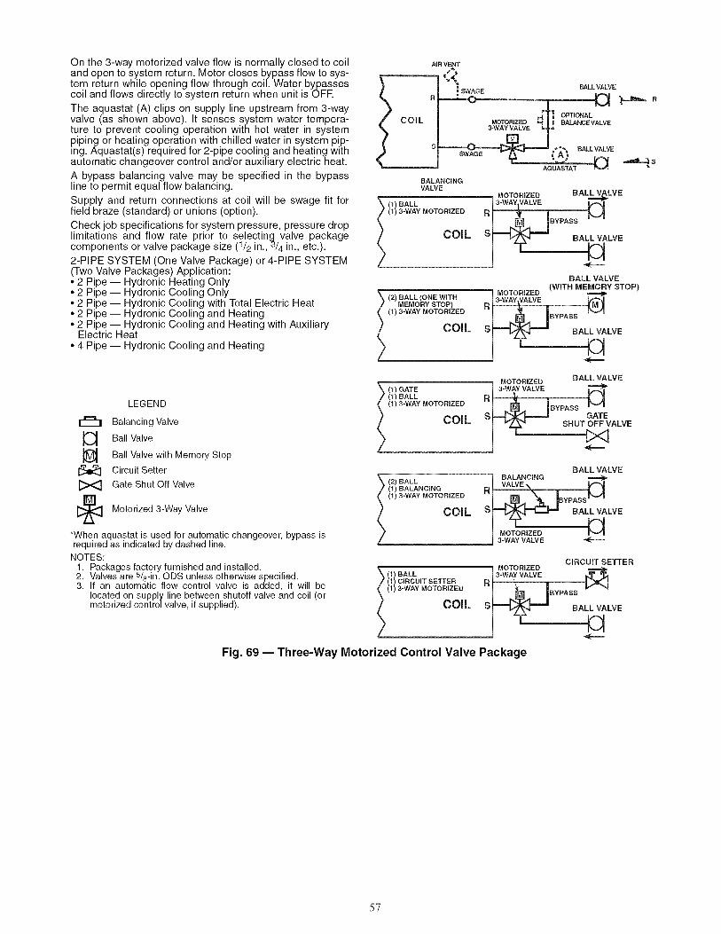
On the 3-way motorized valve flow is normally closed to coiland open to system return. Motor closes bypass flow to sys-tem return while opening flow through coil. Water bypassescoil and flows directly to system return when unit is OFR
The aquastat (A) clips on supply line upstream from 3-wayvalve (as shown above). It senses system water tempera-ture to prevent cooling operation with hot water in systempiping or heating operation with chilled water in system pip-ing. Aquastat(s) required for 2-pipe cooling and heating withautomatic changeover control and/or auxiliary electric heat.
A bypass balancing valve may be specified in the bypassline to permit equal flow balancing.
Supply and return connections at coil will be swage fit forfield braze (standard) or unions (option).
Check job specifications for system pressure, pressure droplimitations and flow rate prior to selecting valve packagecomponents or valve package size (1/2 in.,_/4 in., etc.).
2-PIPE SYSTEM (One Valve Package) or 4-PIPE SYSTEM(Two Valve Packages) Application:• 2 Pipe i Hydronic Heating Only• 2 Pipe i Hydronic Cooling Only• 2 Pipe i Hydronic Cooling with Total Electric Heat• 2 Pipe i Hydronic Cooling and Heating• 2 Pipe i Hydronic Cooling and Heating with Auxiliary
Electric Heat• 4 Pipe i Hydronic Cooling and Heating
COiL
AiR VENT
= BALLVALVE
_o_o_o ,-[TI O_ONAL| I BALANCE VALVE
s -- SWAGE_"'£: a_VALVESWAGE _
R
_S
BALANCINGVALVE
\ ,,_BALL i3.%o_,Z_v_BA'_LVE(1) 3-WAY MOTORIZED R:14J * SSo LLWLW
BALL VALVE(WITH MEMORY STOP)
\ ,2)BALL,ONEW,TR I_°1°_V_E/ MEMORY STOP) R _ M J
_ (1) 3-WAY MOTORIZED I _,.._]..,_ I BYPASS P_/|
CO'L S_LVE
LEGEND
r=h
L3
I_ Motorized Valve3-Way
*When aquastat is used for automatic changeover, bypass isrequired as indicated by dashed line.NOTES:
1. Packages factory furnished and installed.2. Valvesare 5/8-in.ODS unless otherwise specified.3. If an automatic flow control valve is added, it will be
located on supply line between shutoff valve and coil (ormotorized control valve, if supplied).
Balancing Valve
Ball Valve
Ball Valve with Memory Stop
Circuit Setter
Gate Shut Off Valve
BALL VALVE=- ; MOTORIZED\ (1) GATE I 3-WAY VALVE If_.|/ (1)BALL D_, r 1
,,_3-WAYMOTORIZEO°1 ._. IBYPASSM
_ _ATTo_vSHU ALVE
BALL VALVE
z2_ BALL i BALANCING
2 11_BALANCING RI VALVE% • H
_,,,_-WAYMOTOR,ZEDI ,.e_ \ IBYPASSM
COIL sl_-_ BALLVALVE/ _ MOTORIZED H
3-WAY VALVE
CIRCUIT SETTER_- i MOTORIZED
_ (1) BALL 3_ VALVE _/ (1) CIRCUIT SETTER R, - = _ _ I
,,) -WAYMOTORIZEOI IBYPAss (/ CO,LS LVE
Fig. 69 -- Three-Way Motorized Control Valve Package
57
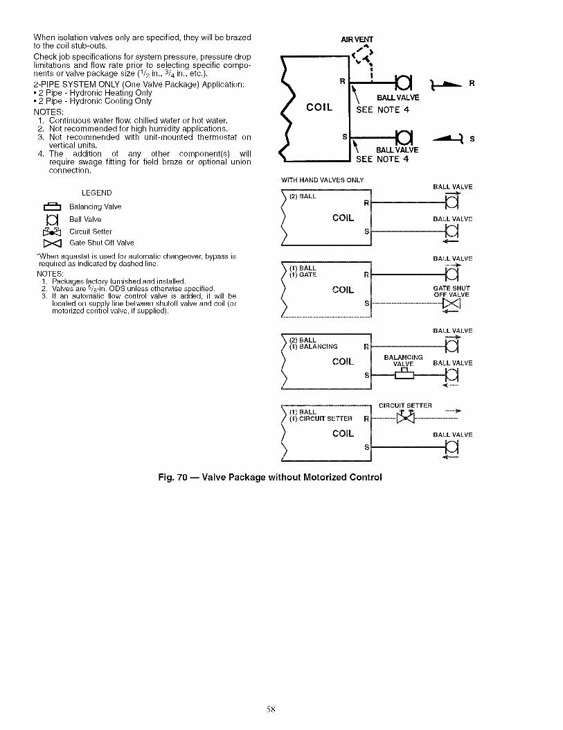
When isolation valves only are specified, they will be brazedto the coil stub-outs.
Check job specifications for system pressure, pressure droplimitations and flow rate prior to selecting specific compo-nents or valve package size (1/2 in., 3/4 in., etc.).
2-PIPE SYSTEM ONLY (One Valve Package) Application:• 2 Pipe - Hydronic Heating Only• 2 Pipe - Hydronic Cooling OnlyNOTES:
1. Continuous water flow, chilled water or hot water•2. Not recommended for high humidity applications•3. Not recommended with unit-mounted thermostat on
vertical units•4. The addition of any other component(s) will
require swage fitting for field braze or optional unionconnection•
LEGEND
Balancing Valve
Ball Valve
Circuit Setter
Gate Shut Off Valve
*When aquastat is used for automatic changeover, bypass isrequired as indicated by dashed line•
NOTES:
• Packages factory furnished and installed•• Valves are 5/8-in• ODS unless otherwise specified•3• If an automatic flow control valve is added, it will be
located on supply line between shutoff valve and coil (ormotorized control valve, if supplied)•
AIR VENT
.,->RI !
1%.,,4
I_ BALLVALVE __.lm_ R
COIL I SEE NOTE 4I
si,sEE _I_T E
WiTH HAND VALVES ONLY
) (2) BALL Ri
BALL VALVE
V1BALL VALVE
1) BALL [
(1) GATE R j
COiL (
BALL VALVE
GATE SHUTOFF VALVE
BALL VALVE
\ BALL )(/ (1) BALANCING RJ F-_\ ,_.,_.,, J BALANCING
ALVE
= CiRCUiT SETTER'_ (1) BALL J _T %
(1) CIRCUIT SETTER R_ L
BALL VALVEH
Fig. 70 -- Valve Package without Motorized Control
58

42C,D,V DRAIN CONNECTIONS -- Install drain line inaccordance with all applicable codes. A continuous pitch of1 in. per 10 ft of condensate drain line run is necessary foradequate condensate drainage. Insulate the drain line toprevent sweating. Extend the drain line straight from the drainpan before making any turns. The installer must provide propersupport for the drain line to prevent undue stress on theauxiliary drain pan.
Install trapped dram line in accordance with all applicablecodes (see Fig. 71). A drain trap may be required by localcodes and is recolmnended for odor control. The differential
height inlet to outlet must be at least 1-in. wg greater than thetotal static pressure of the unit. The differential height of theoutlet to the bottom of the trap must not be less than the totalstatic pressure of the unit.
Provide a trap of at least 2-in. near the end of the drain lineto prevent odors from entering the rooms.
CONDENSATEPAN STUB-OUT
Fig. 71 -- Typical Drain Line Details(42D Unit Shown)
42C,D,V WATER SUPPLY/RETURN CONNECTIONS --Install piping m accordance with all applicable codes. Positionvalves over the drain pan. Be sure valves are in proper operat-ing position and are easily accessible for Mjustment. SeeFig. 67-70. Refer to Fig. 72 for copper water robe and jointmaterial pressure ratings.
If coil and valve package connections will be made with asolder joint, care should be taken to ensure that the componentsin the valve package are not subjected to high temperatures,which may damage seals or other materials. Many 2-positionelectric control valves are provided with a manual operatinglever. This lever should be m the OPEN position during allsoldering operations.
If coil connection is made with a union, the coil side of theunion must be prevented from turning (it must be backed up)during tightening. See Fig. 67-70 for colrunon valve packages.
DO NOT OVERTIGHTENT Overtightening will distort(egg shape) the union seal surface and destroy the union.
NOTE: The prqiect specifications for system pressure, pres-sure drop limitations, and flow rate should be checked prior toselection of specific components or the valve package size.
42C,D,V STEAM CONNECTIONS -- On units with steamheating coils, the maxhnum steam pressure applied to the unitshould never exceed 10 psig. However, when steam is used ona 4-pipe application system with 1-row and 2-row coils themaximum steam pressure should never exceed 5 psig (suitablefor only low pressure steam).
Do not drain the steam mains or take-off through the coils.Drain the mains ahead of the coils through a steam trap to thereturn line. Overhead returns require 1 psig of pressure at thesteam trap discharge for each 2 ft elevation to ensure continu-ous condensate removal.
Proper steam trap selection and installation is necessary. Asa guideline in creating a steam trap locate the steam trap dis-charge at least 12 in. below the condensate return connection.This provides sufficient hydrostatic head pressure to overcometrap losses and ensure complete condensate removal.
42C,D,V DIRECT EXPANSION (DX) REFRIGERANTPIPING--Use the condensing unit manufacturer's recom-mended line sizes and requirements. Suction line must beinsulated for correct operation. Use refrigerant-grade copperlines only. The unit is not applied as a heat pump.
Thermostatic expansion valve (TXV) and sensing bulb arefactory-installed on units when DX coil option is chosen withdistributor and TXV.
NOTE: Ifa hot water coil is used in the reheat position, a field-supplied freezestat must be installed to protect the coil.
TEST AND INSULATE -- When all joints are complete,perform hydrostatic test for leaks. Vent all coils at this time.Check interior unit piping for signs of leakage from shippingdamage or mishandling. If leaks are found, notify your Carrierrepresentative before initiating any repairs. Release trapped airfrom system (refer to Step 7 -- Make Final Preparationssection).
Never pressurize any equipment beyond specific test pres-sure. Always pressure test with an inert fluid or gas, such asclear water or dry nitrogen to avoid possible damage or injuryin the event of a leak or component failure during testing.
All water coils must be protected from freezing after initialfilling with water. Even if system is drained, unit coils maystill have enough water to cause damage when exposed totemperatures below freezing.
Following the hydrostatic test, insulate all piping to preventsweating.
To ensure compliance with building codes, restore the struc-ture's original fire resistance rating by sealing all holes withmaterial carrying the same fire rating as the structure.
59

SYMBOUSKETCH
"'i,I
L..<:
,T.
=,,.d
3
J
Table 5 -- Piping Components
DESCRIPTIONCv FACTOR
112in. 314in.
MANUAL AIR VENT: Threaded brass needlevalve with screwdriver slot for adjustment.
Application -- Body brazed into high point ofheating and cooling coils for bleeding air fromcoil. Standard item on all hydronic coils (notused on steam or DX coils). Should not beused in lieu of main system air vents.
AUTOMATIC AIR VENT: Nickel plated brassvalve, fiber-disc type, with positive shut-off ball-check and quick vent feature via knurled ventscrew.
Application -- Optional replacement for man-ual air vent. Automatically passes minutequantities of air through the fiber discs whichexpand upon contact with water, completelysealing the valve. As air accumulates, the fiberdiscs dry and shrink, repeating the cycle. Notrecommended for removing large quantities ofair encountered during initial start-up or subse-quent draining and refilling. Should not beused in lieu of main system air vents.
SWAGE: Copper tube end expanded to accepta copper tube of the same size for factory orfield brazing.
Application -- Used where possible for all tub-ing joints for best joint integrity.
UNION: Combination wrought copper/castbrass union assembly, solder by solder.
Application -- Used for quick connect (and dis-connect) of valve package components to min-imize field labor and facilitate servicing of unit.
INSERTION TEST PORT: Brass body valvefor acceptance of test probe (up to 1/8 in.diameter).
Application -- Installed on one (or both) sidesof the coil to allow for temperature or pressuresensing. Used for close tolerance water bal-ancing and service analysis.
PSIRATING*
FSTEAM
USE
N/A N/A 400 100 NO
N/A N/A 125 240 NO
PRESSURE TEST PORT: Brass body 1/4 in.service access fitting with removable depres-sor type core.Application -- Installed on both sides of thecoil to allow for pressure sensing. Attach pres-sure gages to facilitate close tolerance waterbalancing.
CIRCUIT SETTER: Variable water flow balanc-ing valve with manual adjustment knob,pointer, percent-open scale, memory stop andintegral pressure read-out ports.
Application -- Used for close tolerance waterflow balancing. Positive shut-off ball valve fea-ture allows usage as combination balancingand shut-off valve.
N/A N/A 300 200 YES
N/A N/A 300 200 YES
N/A N/A 250 250 NO
N/A N/A 400 210 NO
LEGEND
Cv -- Coefficient of VelocityDX -- Direct Expansion
*Check all system component pressure ratings (coils, values,pumps, etc.) with manufacturer and any applicable local or nationalpiping codes prior to specifying system pressure rating.
2.12 3.9 300 250 NO
6O
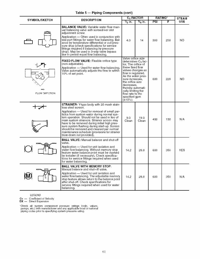
SYMBOUSKETCH
FLOW DIRECTION
Table 5 -- Piping Components (cont)
DESCRIPTION
BALANCE VALVE: Variable water flow man-ual balancing valve with screwdriver slotadjustment screw.
Application i Often used in conjunction withtest port fittings for water flow balancing. Bal-ance by temperature differential or coil pres-sure drop (check specifications for servicefittings required if balancing by pressuredrop). May be used in 3-way valve bypassline to permit equal flow balancing.
FIXED FLOW VALVE: Flexible orifice type(non-adjustable).
Application i Used for water flow balancing.Valve automatically adjusts the flow to within10% of set point.
STRAINER: Y-type body with 20 mesh stain-less steel screen.
Application -- Used for removal of small par-ticles from system water during normal sys-tem operation. Should not be used in lieu ofmain system strainers. Strainer screen mayhave to be removed during initial high pres-sure system flushing during start-up. Screenshould be removed and cleaned per normalmaintenance schedule (provisions for strainerblow-down not provided).
BALL VALVE: Manual balance and shut-offvalve.
Application -- Used for unit isolation andwater flow balancing. Without memory stopfeature water balance point must be markedby installer (if necessary). Check specifica-tions for service fittings required when usedfor water balancing.
BALL VALVE WITH MEMORY STOP:Manual balance and shut-off valve.
Application -- Used for unit isolation andwater flow balancing. The adjustable memorystop feature allows return to the balance pointafter shut-off. Check specifications forservice fittings required when used for waterbalancing.
Cv FACTOR
1/2 in.
RATING*
314in. PSI F
4.0 14 300 250 NO
Valve orifice sizedetermines Cv fac-tor. The orifice ofthese fixed flowvalves changes asflow is regulated.As the water pres-sure increases,the orifice sizedecreases,thereby automati-cally limiting theflow rate to thespecified gpm(+10%).
STEAMUSE
600 220 NO
9.0 19.0Clean Clean 400 150 N/A
14.2 28.6 600 350 YES
LEGEND
Cv -- Coefficient of VelocityDX -- Direct Expansion
*Check all system component pressure ratings (coils, values,pumps, etc.) with manufacturer and any applicable local or nationalpiping codes prior to specifying system pressure rating.
14.2 28.6 600 350 N/A
6!

Table 5 -- Piping Components (cont)
SYMBOUSKETCH DESCRIPTION
2-WAY MOTORIZED VALVE (25 PSI close-off dif-ferential pressure): Electric 2-position flow controlvalve (open/closed). Normally closed body with man-ual override lever. Installed in supply line to unit.
Application -- All standard control and valve pack-ages are based upon normally closed valves (valveelectrically powered open and closed by springreturn when electric power removed). Manualoverride lever allows valve to be placed in the openposition for secondary (unit) flushing, constant waterflow prior to start-up, etc. Manual override is auto-matically disengaged when valve is electrically acti-vated. Consult factory for normally open valveapplications.
2-WAY MOTORIZED VALVE (150 PSI close-off dif-ferential pressure): Electric 2-position flow controlvalve (open/closed). Normally closed body with man-ual override lever. Installed in supply line to unit.
Application -- All standard control and valve pack-ages are based upon normally closed valves (valveelectrically powered open and closed by springreturn when electric power removed). Manualoverride lever allows valve to be placed in the openposition for secondary (unit) flushing, constant waterflow prior to start-up, etc. Manual override is auto-matically disengaged when valve is electrically acti-vated. Consult factory for normally open valveapplications.
3-WAY MOTORIZED VALVE (25 PSI close-off dif-ferential pressure): Electric 2-position flow controlvalve (closed to coil/open to bypass or open to coil/closed to bypass). Normally closed with manualoverride lever. Installed in supply line to unit.
Application -- Same comments as 2-way motorizedvalve except with manual override lever engaged thevalve is open to both ports and water flow will takethe path of least resistance through the valve pack-age (not necessarily 100% through the coil).
3-WAY MOTORIZED VALVE (150 PSI close-off dif-ferential pressure): Electric 2-position flow controlvalve (closed to coil/open to bypass or open to coil/closed to bypass). Normally closed with manualoverride lever. Installed in supply line to unit.
Application -- Same comments as 2-way motorizedvalve except with manual override lever engaged thevalve is open to both ports and water flow will takethe path of least resistance through the valve pack-age (not necessarily 100% through the coil).
Cv FACTOR RATING*
1/2in. 3/4in. PSI F
3.5 3.5 300
4.9 10.3 300
4.0 4.0 300
4.9 4.9 300
STEAMUSE
YES15
200 PSIMAX.
240 NO
200 N/A
240 N/A
LEGEND
Cv -- Coefficient of VelocityDX -- Direct Expansion
*Check all system component pressure ratings (coils, values,pumps, etc.) with manufacturer and any applicable local or nationalpiping codes prior to specifying system pressure rating.
62
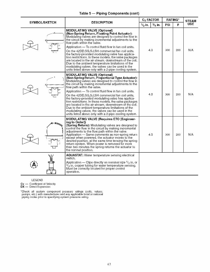
Table 5 -- Piping Components (cont)
SYMBOUSKETCH
J
DESCRIPTION
MODULATING VALVE (Optional)(Non-Spring Return, Floating Point Actuator):Modulating valves are designed to control the flow inthe circuit by making incremental adjustments to theflow path within the valve.
Application -- To control fluid flow in fan coil units.
On the 42DD, SG,SJ,SH commercial fan coil units,the factory-provided modulating valve has applica-tion restrictions. In these models, the valve packagesare located in the air stream, downstream of the coil.Due to the ambient temperature limitations of themodulating valves, the valves can be used in theunits listed above only with a 2-pipe cooling system.
MODULATING VALVE (Optional)(Non-Spring Return, Proportional Type Actuator):Modulating valves are designed to control the flow inthe circuit by making incremental adjustments to theflow path within the valve.
Application -- To control fluid flow in fan coil units.
On the 42DD, SG,SJ,SH commercial fan coil units,the factory-provided modulating valve has applica-tion restrictions. In these models, the valve packagesare located in the air stream, downstream of the coil.Due to the ambient temperature limitations of themodulating valves, the valves can be used in theunits listed above only with a 2-pipe cooling system.
MODULATING VALVE (Requires ETO [Engineer-ing to Order])(Spring Return): Modulating valves are designed tocontrol the flow in the circuit by making incrementaladjustments to the flow path within the valve.Application i Same comments as non-spring returnexcept when powered, the actuator moves to thedesired position, at the same time tensing the springreturn system. When power is removed for morethan two minutes the spring returns the actuator tothe normal position.
AQUASTAT: Water temperature sensing electricalswitch.
Application -- Clips directly on nominal size 1/2 in. or3/4 in. copper tubing for water temperature sensing.Must be correctly located for proper controloperation.
Cv FACTOR
1/2 in. I 3/4 in.
4.0
4.0
4.0
RATING*
PSI F
300
300
300
STEAMUSE
200 N/A
200 N/A
200 N/A
LEGEND
Cv -- Coefficient of VelocityDX -- Direct Expansion
*Check all system component pressure ratings (coils, values,pumps, etc,) with manufacturer and any applicable local or nationalpiping codes prior to specifying system pressure rating,
63
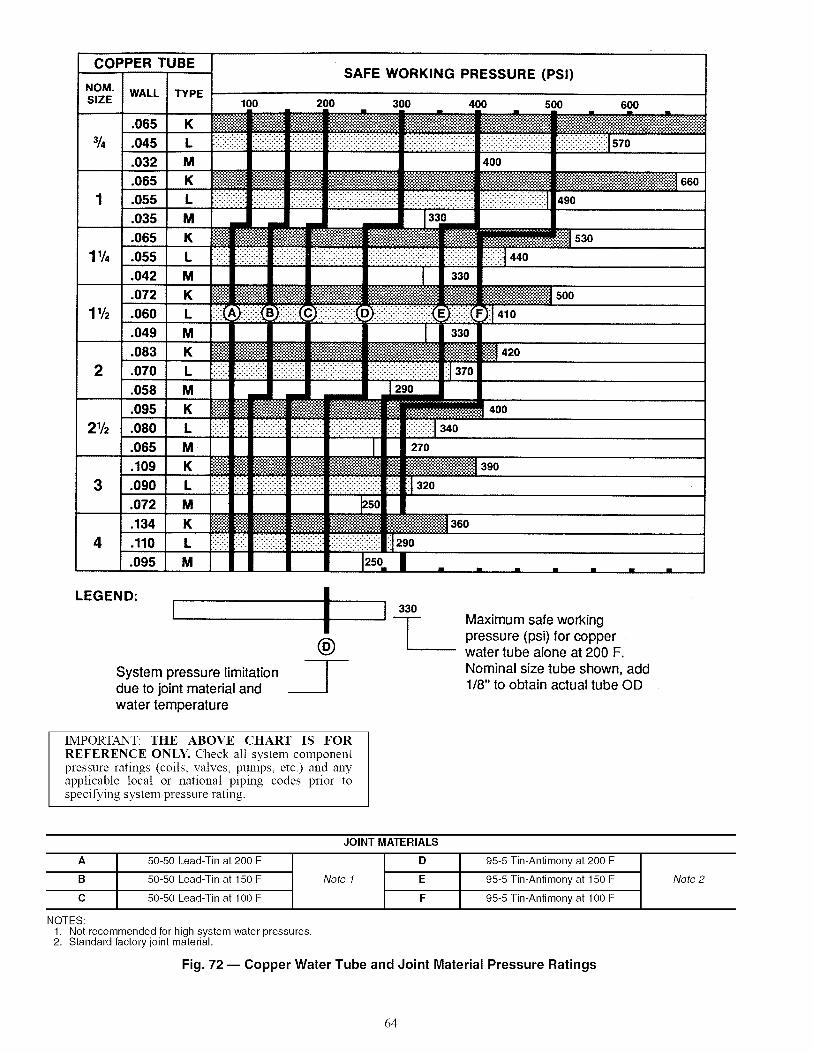
COPPER TUBESAFE WORKING PRESSURE (PSI)
NOM. WALL I TYPESIZE 100 200 300 400 500 600
.065
3/,=1.045
.032
.065
1 I .055.035
.065
K
L
M
K
L
M
K
11/4 1.0551 L.042
.072
11/2 I .060.049
.083
2 I .o7o.058
.095
21/2 I .080.065
.109
3 I .o9o.072
.134
4 I .11o095
M
K
L
M
K
L
M
K
L
M
K
L
M
K
L
M
LEGEND:I
System pressure limitationdue to joint material andwater temperature
iiiii!i!iii!ii i ! :+:: - ..... 490
530
570
440
500
410
420
400
340
270
390
320
360
290
i®
330Maximum safe workingpressure (psi) for copperwater tube alone at 200 F.Nominal size tube shown, add1/8" to obtain actual tube OD
IMPORTANT: THE ABOVE CHART IS FOR
REFERENCE ONLY. Check all system componentpressure ratings (coils, valves, pumps, etc.) and anyapplicable local or national piping codes prior tospecifying system pressure rating.
A
B
C
NOTES:
50-50 Lead-Tin at 200 F
50-50 Lead-Tin at 150 F
50-50 Lead-Tin at 100 F
JOINT MATERIALS
D
Note 1 E
F
95-5 Tin-Antimony at 200 F
95-5 Tin-Antimony at 150 F
95-5 Tin-Antimony at 100 F
1. Not recommended for high system water pressures,2. Standard factory joint material,
Fig. 72 -- Copper Water Tube and Joint Material Pressure Ratings
Note 2
64

Step 3 m Make Electrical Connections m Referto unit nameplate for required supply voltage, fan and heateramperage and required circuit ampacity. Refer to unit wirediagram for unit and field wiring. Since each project is dif-ferent and each unit on a project may be different, the in-staller must be familiar with the wiring diagram and name-plate on the unit before beginning any wiring. Make sure allelectrical connections are in accordance with unit wiring di-agram and all applicable codes. The type and sizing of allwiring and other electrical components such as circuitbreakers, disconnect switches, etc. should be detennined bythe individual .job requirements, and should not be based onthe size and/or type of connection provided on the equip-ment. All installations should be made in compliance withall governing codes and ordinances. Compliance with allcodes is the responsibility of the installing contractor.
The fan motor(s) should never be controlled by any wiringor device other than the factory-supplied switch or thermostat!switch combination unless prior factory authorization isobtained. Fan motor(s) may be temporarily wired for useduring construction only with prior factory approval and onlyin strict accordance with the instructions issued at that time.
On 42S vertical stack units, the unit electrical supply is de-signed to enter through knockouts provided in the top of theunit and pass down through matching knockouts in the controlsection top. Where space allows, power may be pulled directlythrough the side of the cabinet into the control section.
All components furnished for field installation by either thefactory or the controls contractor should be located andchecked for proper function and compatibility. All internalcomponents should be checked for shipping damage, and anyloose connections should be tightened to lnimmize problemsduring start-up.
Any devices such as fan switches or thennostats that havebeen furnished from the factory for field installation must bewired in strict accordance with the wiring diagram that appearson the unit. Failure to do so could result in personal injury ordamage to components, and will void all manufacturer'swarranties.
Units with factory-supplied and factory-installed aquastatsmay be shipped with the aquastats mounted on a coil stub-out.If this is the case, remove the aquastat before installing valvepackage. When reinstalling aquastats, consult the factory-piping diagram in the submittal for proper location. If the valvepackage is field-supplied, the aquastat must be installed in alocation where it will sense the water temperature regardless ofthe control valve position. A bleed bypass may be required toguarantee proper aquastat operation. The aquastat bypass lineallows a small amount of water to flow from the supply to thereturn piping when the control valve is closed.
NOTE: The aquastat must be able to sense whether theflowing water is being chilled or heated and switches a contactclosed to provide automatic summer or winter changeover forthe system. When a two-pipe cooling/heating system withoptional auxiliary electric heat is desired, an additionalaquastat is required.
All field wiring must be in accordance with governingcodes and ordinances. Any modification of unit wiring withoutfactory authorization will invalidate all factory warranties andnullify any agency listings. The manufacturer assumes no re-sponsibility for any damages and/or injuries resulting from hn-proper field installation and/or wiring.
IMPORTANT: Wiring diagrams shown depict typicalcontrol functions. Refer to unit wiring label for specificfunctions.
Units may be equipped with line voltage controls or24 VAC control systems. The following descriptions are fortypical control sequences only. For detailed control operatingsequence, refer to thermostat operating instructions.STANDARD WIRING PACKAGES
Manual Fan Control -- On vertical cabinet units, a fan-speedswitch may be furnished unit-mounted and wired. See Fig. 73.On vertical furred-in units and horizontal units, the switch maybe shipped separately on a decorative wall plate for fieldmounting and wiring. See Fig. 74.
The standard switch has LOW, MEDIUM, HIGH and OFFpositions plus an auxiliary contact to energize thermostats,valves, dampers, etc.
NOTE: Wiring diagrams are for typical applications. If othervoltages for heaters or controls are specified, wiring may differfrom that shown. Refer to wiring diagram on unit blower hous-ing for unit specific wiring.
Thermostatic Electric Valve Control 2-Pipe -- A thermo-statically controlled 2-position valve provides superior controlto fan cycling. With this control, the fan runs continuously un-less it is manually switched to the OFF or AUTO position. Thefan must be on before the valve can be opened to supply waterto the coil.
This system can be used for normal 2-pipe changeover systemsand can also be furnished for cooling-only or heating-only ap-plications by omitting the changeover and specifying whichapplication is intended. See Fig. 75 and 76 for line voltage con-trol. See Fig. 77 and 78 for 24-v control. Wiring diagrams showtypical applications. Refer to wiring diagram on unit blowerhousing for unit specific wiring.
65

L RED
" _ H BLU/BLOWERF-
',,MOTO</H S,KCOP1
L RED
M BLUH BLK
WHTCOH
LZI I
L2 or N I_
EOUIPMENT(iROUND
EQUI PMENTGROUND
SERVICESWITCH _
(OPTIONAL) }_ _
208/240V
IF_4_ RE]} RE]}-- T,"_/ I.__ I, X BLU ]_LU
__ i!_ I, ]}LI< BLI<
I731 RED
_ RE]}
BLU
BLK
RE]}
FUSES
(OPTIONAL)
=@l@ BLK I_ BLK
1GROUND
_(REQUIRED OPTION W/O SER, SWITCH)
SWITCH
Fig. 73 -- No Controls -- UnitiMounted 3-Speed Switch Only
UNIT MOUNTEDJUNCTION BOX(ES)
SWITCH PLATE( 2 X 4 ) PACKAGE No, 70390001-07
4.
REMOTE DEVICE BOX14,5 IN3 MIN,
EQUIPMENT
GROUND
LI
L2 or N ......
NOTES:1. Motors are thermally protected.2. Use copper conductors only.3. See unit nameplate for power supply. Provided
disconnect means and overload protection asrequired.Unit-mounted thermostats are not recommended forfan control because of poor temperature sensing. Fancontrol not available on 42VC,VE lowboy units.
Fig. 74 -- No Controls -- WalliMounted 3-Speed Switch Only
66

A120-V WHT ALL OTHERS BLK
NEC CLASS 1 WIRING
_____L__R E_D........
............. -_>3>4_\MDTDR jH BLK I I.............
CDM t)L_
L RED
M_oL TO_/_M BLU
H BLKWHT
CDM
SERVICE
SWITCH 9.,....(OPTIONAL)
LI-- -i--O== =_---_ = =I
L2 or" N- _ff--o_--_--
| 208/240v
EQUIPMENT _ [ ONLYGROUND -- - .... ___.
EQUIPMENT
GROUND
RED
BLU
BLK
WHT÷
RED
BLU
BLK
WHT_
FUSES
(OPTIONAL)
-of'_
I._I_ I_ I_ I_b I_=I==
T÷156 _ N z E _ _ / iTISTAT I_
Li _ , __ ') 8 7 3
c x !
...... lI \
,,f ......
WHT_ ! WHT* [ (i(:-,_
GROUND(REQUIRED OPTION W/O SERVICE SWITCH)
RA SENSDRBLK
BLKRED I _ mT_'_-_
BLK r---1- --Z&--_LK--_ V A L V Eli
I IL___J
VALVE (DPTIDNAL)=
-FACTORY DR FIELD PROVIDED,
NOT TD EXCEED T'STAT RATING,
Fig. 75 -- 42SG,SH,SJ,VA,VB,VC,VE,VF 2-Pipe Heating and Cooling withAutomatic Changeover- Unit-Mounted Thermostat (Line Voltage)
RELAY COIL LETTER REFERS TO
RELAY P/N 706654-XX
VOLTS A B
24 Oi 06
120 02 07
208 03 08
240 04 09
277 05 10
L RED
CDM
A120-V Writ ALL OTHERS BLK
NEC CLASS 1 WIRING
L RED
CDM
SERVICE
SWITCH ?_(DPTIONAL)
L1 -- _ro===_--_====
L2 or N -- __==.M
EQUIPMENT 2os/24ovGROUND -- LnNLY_
EQUIPMENT
GROUND
WHT÷
RED
DLU
BLK
WHT_
FUSES
(OPTIpNAL _BLK
BLK
WHT_
GROUND
(REQUIRED OPTION W/O SERVICE SWITCH)
Fig. 76 -- 420,S,V and 42D (600-1000) 2-Pipe Heating and Cooling with Automatic Changeover-Remote/Wall-Mounted Thermostat (Line Voltage)
67

EQUIPMENT
GRDUND
PUR
YEL
CHANGE OVER SENSOR
_xc
I]
#it F------7F4]_B LK/ I
_$]__L_VALVEIL___J
Fig. 77 -- 42SG,SH,SJ,VA,VB,VF 2-Pipe Heating and Cooling with Automatic Changeover --Unit-Mounted Debonair ¢ Thermostat (24-v), Duct Sensor
REMOTE :DEVICE ]tDX x<I
NEC CLASS 2 WIRING
--_- I___E_L.
// \k M BLU
BLDWERT ....
_\MOTOR /_H_2L£_\ _ ____/_ _ _ aT
co_,
L RED
/'BLDWERT--
_ WHT
SERVICE coM
SWITCH (",_(OPTIONAL)) _
.._2___L__LI -- 4-0,-_11_--.
I
L£ or" N -- J--O, _----EQUIPMENT I _08/240V
_0UN_-.____-"_L_'_=___
-- ] RED
k#3_ ...... ]I I _LR I
I I WNT_ I I_>i>+...._,,K_J III
IIIIII
-,iL.L-II
_LIJ iI u
ILK !1
_WHT_FUSES
IGROUND
_ (OPTIONAL)
EQUIPMENT
GROUND
T' STAT
RS+5 RS R G Y1 G3 W! G2 C H20 CKI
o/c
_OR5 .
CHANGE OVER SENSOR
PUR
YEL
Fig. 78 -- 42C,S,V (except VG), and 42D (600-1000 cfm 2-Pipe Heating and Cooling withAutomatic Changeover -- Remote/Wall-Mounted Debonair e Thermostat (24-v)
Gic F------qF_]__ LkJ I
L] _-_-_Kq V#LVE IL___J
68

Thermostatic 2-Pipe Auxiliary. Electric Heat with ValveControl -- This system, also called twilight or intermediateseason electric heat, goes a long way towards solving thespring and fall control problems of 2-pipe systems.
Chilled water can be run late into the fall, turned on early inthe spring and heat will still be available to all units wheneverrequired.
In winter the system is switched over to hot water. Twochangeover devices are required for this. One device switchesthe action of the thermostat and the other locks out the electricheat when hot water is in the coil.
With this system, the fan runs continuously unless manuallyswitched to OFF or AUTO position. Fan must be on beforethermostat can send signal to open chilled water valve or turnon electric heater.
Two control methods are available:
1. Use the standard automatic changeover thermostat with adead band between heating and cooling.
2. Use a manual changeover thermostat. With this methodonly one changeover is required.
Be sure to include a 2-way or 3-way electric valve with thissystem.
NOTE: Wiring diagrams are for typical applications. If othervoltages for heaters or controls are specified, wiring may differfrom that shown. See Fig. 79 for line voltage control. SeeFig. 80 and 81 for 24-v control. Refer to wiring diagram onunit blower housing for unit specific wiring.
oREMOTE DEVICE BOX
UNITMOUNTED - - --I -- --I -----ffJ BOX _ I i i i
"\ I I I I
QUICK CONNECT , ; i [ I
OPTIONAL I
L RED _ RED
MOTORHBLK _) BLK
COM _) _W,T
EQUIPMENT @
GROUND
L2 or N
L1
LIM IT SWITCH
THERMOSTAT PART # 702893-36
If--- 1--i t
II
t II II II II II II Ii !
I i /I I
II
]
CONTACTOR *WHT
BLK _ BLK
*WHT
"1 rI II I
o
PUR / /\\
z
{(RED / /
\\BRN / /
b22J
I
I !
AQUASTATS
BLK _- ;E_BLU
BLK _-- ;E_RED (°_.BLU
VALV E
BLK F
IA WHT I I
i L----J i
/\L_
G) It- r-
z Io I ^i:_ ,, ONLY 120v WHT/ALL OTHERS BLK
, i zL---L--'-J
Fig. 79 -- 42C,S,V (except VG), and 42D (600-1000 cfm) 2-Pipe Heating and Cooling withAuxiliary Heat -- Remote/Wall-Mounted Thermostat (Line Voltage) and Dual Power Source
69
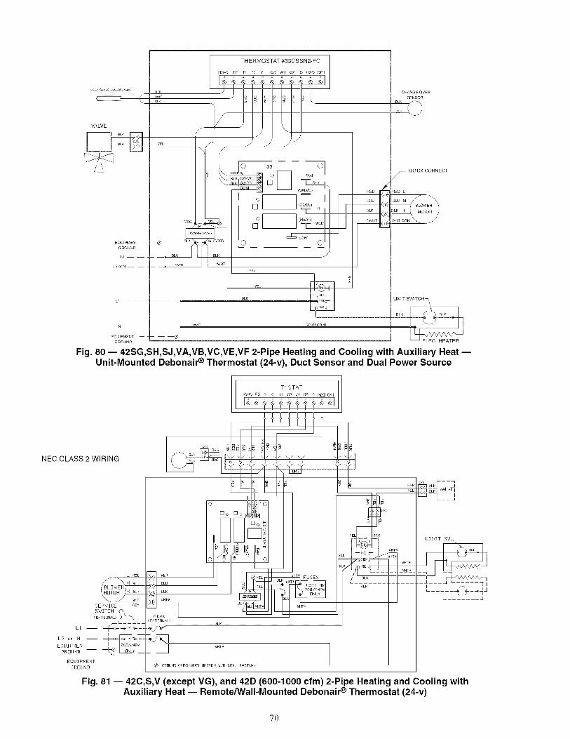
DUC_SENSOR33CSSENDS
c----q
VALVE
EQUIPMENT --
GROUND
L1 ----
L2orN
N
EQUIPMENT
GROUND
nEDWHrBLK
ORG
EBLK
-- -- BLK
WHT
RED _BLU m, ,[
_LK k_4J
BLK _
QUICK CONNECT
RED L
__BLUM BLOWER3LK H MOTOR
Fig. 80 -- 42SG,SH,SJ,VA,VB,VC,VE,VF 2-Pipe Heating and Cooling with Auxiliary Heat --Unit-Mounted Debonair _ Thermostat (24-v), Duct Sensor and Dual Power Source
T' STAT
IRS+5 RS R G Y[ G3 _1 GE C HEO Cl<l
NEC CLASS 2 WIRING
L RED
__ J _HT
SERVICE CI]M
SWITCH 0,,_< I]PTII]NI_L) /_ _\
i
EQUIPHENT I _i]8/_40V
GRDUND-- --_&___:=EQUIPHENT
GIRFIUND
RED
I_LU
9LK
WHT_
( OPT] BNAL)
_ GRBUN]](REI]UIRED I]PTII]N W/I] SER, SWITCH)
_HT*
HT_
a/c r---_
YEL /I ITL_ VALVEIq
LIMIT gW_
BLK
__x____--q---_ /-_q
Fig. 81 -- 42C,S,V (except VG), and 42D (600-1000 cfm) 2-Pipe Heating and Cooling withAuxiliary Heat -- Remote/Wall-Mounted Debonair ® Thermostat (24-v)
70

Thermostat 2-Pipe Total Electric Heat with Valve Con-trol -- With this system, the complete heating requirement forthe space is provided by the electric heater; the water system isnever changed over for heating. It is therefore possible, just aswith 4-pipe systems, to have heating or cooling at any thne ofthe year.
The fan runs continuously unless it is manually switched toOFF or AUTO position. Fan must be on before thermostat cansend signal to open chilled water valve or turn on electricheater.
Normally, an automatic changeover thermostat with a deadband between heating and cooling is used, but a manualchangeover thermostat is also suitable. A 2-way or 3-way valvemust also be used so that the chilled water is off whenever theheater is on. No changeover device to sense water temperatureis necessary.
NOTE: Wiring diagrams are for typical applications. If othervoltages for heaters or controls are specified, wiring may differfrom that shown. See Fig. 82 for line voltage control. SeeFig. 83 and 84 for 24-v control. Refer to wiring diagram onunit blower housing for unit specific wiring.
REMOTE DEVICE BBX--_
QUICK
CONNECT-_
,,EF.,q_c_"
V L_I,I BLK_',; ,co:z_>im>I BRNE2Jm
SERVIOE%.SWITCHf ,_
LI - -- -_ -- =,_--",---!
LZ or N - -- 4= -J--,_-:I I_o8,24ov
EQUIPMENT _ L u_YGROUND -- -- .......
ORG PUR
T0THERMOSTAT PART # 702893-36
1 2 8 9
_WHT
RED ]BLU
BLK
CAPACITOR *VHT
/ *VHT r- .... 1
. _o_o"v_.LoNLY ._]
_Tm_> BLK F
. _ _ VALVEI=_ I LI _ BLK F - - -I
II I
CBNTACTBR l _R
Fig. 82 -- 42C,S,V (except VG), and 42D (600-1000 cfm) 2-Pipe Cooling with Total Electric Heat --Remote/Wall-Mounted Thermostat (Line Voltage)
71

DUCTs_-Nsr,n _4_s>','_E'_
...........................................................BLK I/_ IBLK
--_ _ L _RE_D__
/I _'\ M BLU/ BLOWERT ....
I\MDTDR /LH_ BL_K_
"-_ _J_ _ _NT_ _CDM
L REn
\MOTO z 2:
(OPTIDNAL)c\SERVICESWITCH > \
L!-- __ _ _I_
L2 or N- _ ___I_
EOU IPMENT 20e/24ov
GROUND- _ I I]NLY ___ __
EQUIPMENT
GROUND
I---9 RED
t>_---,<)sTD_BL__I I BLI<_>p)---I I WHT÷
L_ .... "II
\
FUSES(OPTIONAL)
I
RS+5 RS R 0 Y2 G3 Wl G2 C H20 CKI
(OPTIONAL>
-- -- _ GROUNI}(REQUIRED W/O OPTIONAL SER, SWITCH>
<<__p
YELYEL
Yj_L
_CBN_ i WHT÷
Iz - __I-L .........
WHT_
Q/c F - - --9
E_ WLVElL___J
NOTE: Units may have 2 or 4elements. Elements wired inparallel.
WHT_ LIMIT SW
F ............. ]_LK
iI r BLK1 tt IL. 1
I 1 r---:--I,.-4--- ,_ "_ I_LK I J
l t WriT÷ I / \ ./ I1 ,="..... L--J J
I I i ........I I I il I I I LIMIT SW_
I I I _ ]_LK II_ _l_ _ _j _ ..... _,._ _ _ _._4_ H_7
L_I-_....... W_.2:J___JII I I L-b_" ^ A ^ ^ _-JI I L_:i vvvvv
1 \ / I
Fig. 83 -- 42SG,SH,SJ,VA,VB,VC,VE,VF 2-Pipe Cooling with Total Electric Heat --Unit-Mounted Debonair e Thermostat (24-v) and Duct Sensor
REMOTEDEVICEBOX_\\\\
VALVE
E%;_ggT--
L1 --
L2orN -- _ =
LI -- --
N
EQUIPMENT --
GROUND
YEL
lTHERMOSTAT #33CSSN2-FC
IRS+5 RS R G Y1 G3 Wl G2 C H20 CK1
I I I I I--I NECCLASS2WIRING
33ZCRLYBRD 0
0 _ FAN
(VALVE)
....LOW
©
/FRpn r'_
I:_< i
*WHI i, i
©
I
Q
BLK
"WHT
QUICK CONNECT/
RED L
BLU M BLOWER
BLK H MOTOR
LIMIT SWITCH
BL I .... I
Fig. 84 -- 42C,S,V (except VG), and 42D (600-1000 cfm) 2-Pipe Cooling with Total Electric Heat --Remote/Wall-Mounted Debonair e Thermostat (24-v) and Dual Power Source
?2
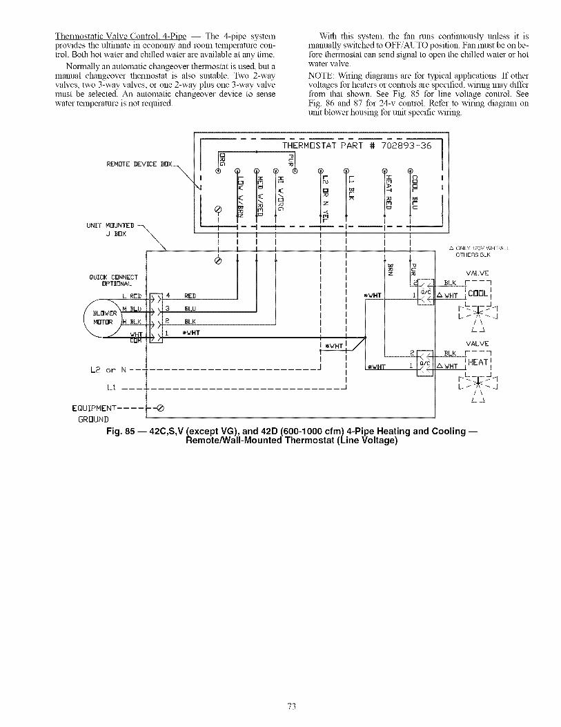
Thermostatic Valve Control. 4-Pipe -- The 4-pipe systemprovides the ultimate in economy and room temperature con-trol. Both hot water and chilled water are available at any time.
Normally an automatic changeover thermostat is used, but amanual changeover thermostat is also suitable. Two 2-wayvalves, two 3-way valves, or one 2-way plus one 3-way valvemust be selected. An automatic changeover device to sensewater temperature is not required.
With this system, the fan runs continuously unless it ismanually switched to OFF/AUTO position. Fan must be on be-fore thermostat can send signal to open the chilled water or hotwater valve.
NOTE: Wiring diagrams are for typical applications. If othervoltages for heaters or controls are specified, wiring may differfrom that shown. See Fig. 85 for line voltage control. SeeFig. 86 and 87 for 24-v control. Refer to wiring diagram onunit blower housing for unit specific wiring.
REMOTE DEVICE BOX_
\
UNIT MOUNTEDJ Box __i i l l! ! ! !
-i I- l
i
THERHOSTAT PART # 702893-36
t I- T
QUICK CONNECTOPTIONAL
L REB
L2 or N----
L1
EQUIPNENT ....
GRDUNB
4 REB
3 BLU
2 BLK
I _/HT
cIImIJ
=..._
_WHT
Z
=ii
Q/C
A ONLY 120V WHT/ALLOTHERS BLK
VALVE
BLK r "3i
_wH__CDOL i
/\
L3
Fig. 85 -- 42C,S,V (except VG), and 42D (600-1000 cfm) 4-Pipe Heating and Cooling --Remote/Wall-Mounted Thermostat (Line Voltage)
73

F-7<OPTIONAL) I 4 1
L£JCT SENSOR
( I---,....... i
RED I _,)_ RED/ _ - _ .5/! .......
/ WHT I I_---4_+ .........", BL K I I I ......
III
L:L_ .... L__REj__
/ \ M BLU
I BLI3WERT ....
LMDTDR /LH- 2L£_
"..j J_ _ 2_H_T_ _CBM
L RED
,/ _HT
SERVICE CaM
SWITCH O,
<OPTIONAL) _ _\_t L__
L1 -- _o, -- _../___.I
L2 or N -- Vo,_-_--_EQUIPHENT I 808/a40v
GROUND I _b _ ONLy___ I
EQUIPMENT
GRDUN]I
_qq_D)4/_ ....... 7
7"_/7...... 1 1
"A/! III\_\! WHT÷ II-f7±/T .... 7 IIL / I II
I II
I III II
RED I I ! _ REDIHVl IIIL,_I9Lb I! _r BLU
J_l I I_BLK !_ BLKi
WHT_
-%_%
J
T'STAT
RS+5 RS R G YI GS WI G2 C H20 CK!
-J II _,o
- +i iui
_LI<
WHTm
GROUND (REQUIRED OPTION W/O SER, SWITCH)
G
YEL
YEL
Fig. 86 -- 42SG,SH,SJ,VA,VB,VC,VE,VF 4-Pipe Heating and Cooling --Unit-Mounted Debonair ® Thermostat (24-v) and Duct Sensor
BRN
YEL
YEL
PUR
Q/C F------7
F<, _LKJ, HEAT
:E__4J-S--LKq VALVE
L___J
Q/C F------q
F_Kq coaL
J__<j__S__LK_ VALVEL___J
REMOTE DEVICE BOX --
VALVE
VALVE
EQUIPMENT--GROUND
L1 - I
L2orN - -- _
BRN
THERMOSTAT #33CSSN2-FC i
R_5_S R G YI G3 Wl G2 C H_O _1 1
10° t_t + + +,,,? IN °EIc!Jss 2 WIRING
LL2Z_
_L__ _-"
_ 33ZCRLYBRD O1o _11 I ,=_t_ "L_[]
0
I []
I o[]
©
(VALVE) I
(ooo_)I I=rn'l
(_:_) MED
LOW
ol
/
_LU 3
QUICK CONNECT/
RED L
?
Fig. 87 -- 42C,S,V (except VG), and 42D (600-1000 cfm) 4-Pipe Heating and Cooling --Remote/Wall-Mounted Debonair e Thermostat (24-v)
?4

Step 4 E Make Duct Connections E Install allductwork to and from unit in accordance with proiect plans,specifications, and all applicable codes. Duct construction mustallow unit to operate within duct external static pressure lhnitsas shown on job submittals. Units designed to operate withductwork may be damaged if operated without intended duct-work attached.
Units provided with outside air should have some methodof low-temperature protection to prevent freeze-up. This pro-tection may be any of several methods, such as a low tempera-rare thermostat to close the outside air damper or a preheat coilto temper the outside air before it reaches the unit. It should benoted that none of these methods will adequately protect thecoil in the event of power failure. The safest method of freezeprotection is to use glycol in the proper percent solution for thecoldest expected air temperature.
Insulate ductwork as required. Use flexible connections tominimize duct-to-unit aligmnent problems and noise transmis-sion where specified.
Set unit markings for minimum clearance to combustiblematerials and first 3 ft of ductwork. Install ductwork, accessorygrilles and plenums so that they do not restrict access to filter.The manufacturer assumes no responsibility for undesirablesystem operation due to improper system design, equipment orcomponent selection, and/or installation of ductwork, grilles,and other related components.
Prevent dust and debris fvm settling in unit. If wall finishor color is to be spray applied, cover all openings to pre-vent sprayfvm entering unit. Failure to do so could resultin the reduction of unit efficiency.
Step 5 _ Frame and Finish Unit _ Models 42SG,SH, SJ, SU and SM have factory enclosures and may be fin-ished with normally accepted wall covering. However, drywallsecured with adhesive bonding alone is not recolmnended.
The 42S units are designed to have gypsum board or othertypes of wall board applied directly to the unit cabinet surfaceto a maximum combined thickness of 5/s-inch. Use low-pro-file sheet metal panhead screws to secure wallboard to unitframe. Fasteners may penetrate the cabinet no more than 1/2inch.
These fasteners must be located to avoid damage to internalcomponents and wiring in the same manner as anchoring fas-teners. Do not apply sheet metal screw or nails where they canpenetrate coil, riser pipes, or electrical junction box and race-ways.
Do not secure wallboard to drain pan edges or to controlbox enclosure. Condensate leaks or electrical shorts may result.
An alternate method of enclosing the unit is to frame one ormore sides with studding and apply the wall board to this fraln-ing. This method requires specific unit features and return ac-cess panels when used on the return-air side of a unit. Units notproperly equipped will exhibit poor cooling and/or heating per-formance and could experience excessive or premature compo-nent failures.
Prevent sheetrock dust or other debris from settling on coilfins, motor-blower assembly or other unit interior surfaces.
Return access and exposed cabinet units may be furnishedwith a baked enamel finish. Small scratches in this finish maybe repaired with touch-up paint available from the factory.Some colors of touch-up paint are available in aerosol contain-ers and all touch-up paint is available in pint, quart, and gallonCallS.
Proper safety procedures should be followed regardingventilation and safety equipment during touch-up andrepainting. The manufacturer's directions should be fol-lowed for the products being used.
To repaint the factory-baked enamel, the finish should beprepared by light sanding with no. 280 grit sand paper orno. 000 or no. 0000 fine steel wool. The surface may also bewiped with a liquid surface etch cleaning product such as "NoSand" or "Pasceo." These items should be available at most
paint product stores. It should be noted that the more conscien-tiously this preparation is done, the more effective it will be.
After this preparation is accomplished, the factory finishshould provide excellent adhesion for a variety of air-dried topcoats. Enamel will give a more durable, higher gloss finish,while latex will not adhere as well and will give a dull, softerfinish. Top coats involving an exothermic chemical process be-tween two components, such as epoxies and urethanes, shouldbe avoided.
Factory aerosol touch-up paint may require a number oflight "dust coats" to isolate the factory-baked enamel finishfrom the quick drying touch-up paint.
Step 6 -- Cut Out Openings for Grilles andThermostats _ On all units with optional supply-air orreturn-air grilles, dampers, thermostats, and switch plates, cutout openings where specified on the job plans. Be careful not tocut wires, piping or structural supports.
For remote-mounted thermostats use a steel thermostat
shield ring to protect drywall from thermostat wiring whereapplicable.
If not included on the unit or furnished from the factory,supply and return grilles should be provided as recolrnnendedin the product catalog.
Step 7 _ Make Final Preparations
1. Turn offpower to the unit (open unit electrical disconnect).
2. Install thermostats and perform any other final wiring asapplicable. Check the unit for any loose wires.
3. Perform a final visual inspection. All equipment, ple-nums, ductwork, and piping should be inspected to verifythat all systems are complete and properly installed andmounted, and that no debris or foreign articles such as pa-per or drink cans are left in the units or other areas. Cleandirt, dust, and other construction debris from unit interior.Be sure to check fan wheel and housing.
4. Rotate fan wheel by hand to be sure it is free and does notmb housing. Check that wing nuts securing fan assemblyto fan deck are tight.
5. Ensure all panels and filters are installed before checkingfan operation. Turn on power to the unit.
6. Install filter in frame at front of coil. If field-suppliedfilters are used, be sure size is as specified in Tables 1-4.
IMPORTANT: Do not start up or operate unit withoutfilter. Be sure filter and unit interior are clean. Failure to
do so could result in damage to the equipment or build-ing and furnishings and/or void all manufacturer'swarranties.
7. ECM (Electronically Colmnutated) Blower:
If the unit is equipped with an ECM blower, additionalsteps may be required during the air balancing process.The ECM blower is controlled by one of three controlboards, depending on the options ordered with the unit.
75
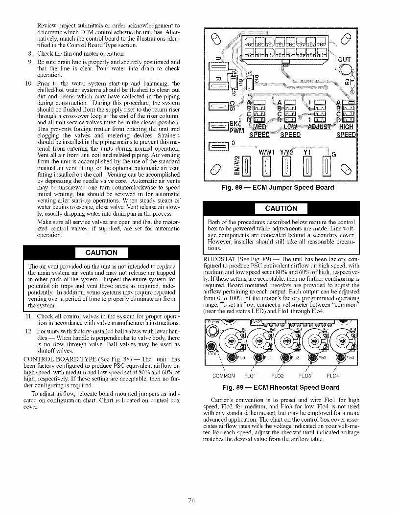
8.
9.
10.
Review prqject submittals or order acknowledgement todetermine which ECM control scheme the unit has. Alter-natively, match the control board to the illustrations iden-tified in the Control Board Type section.
Check the fan and motor operation.
Be sure dram line is properly and securely positioned andthat the line is clear. Pour water into drain to checkoperation.
Prior to the water system start-up and balancing, thechilled/hot water systems should be flushed to clean outdirt and debris which may have collected in the pipingduring construction. During this procedure, the systemshould be flushed from the supply riser to the return riserthrough a cross-over loop at the end of the riser column,and all unit service valves must be in the closed position.This prevents foreign matter from entering the unit andclogging the valves and metering devices. Strainersshould be installed in the piping mains to prevent this ma-terial from entering the units during normal operation.Vent all air from unit coil and related piping. Air ventingfrom the unit is accomplished by the use of the standardmanual air vent fitting, or the optional automatic air ventfitting installed on the coil. Venting can be accomplishedby depressing the needle valve core. Automatic air ventsmay be unscrewed one turn counterclockwise to speedinitial venting, but should be screwed in for automaticventing after start-up operations. When steady steam ofwater begins to escape, close valve. Vent release air slow-ly, usually dripping water into drain pan in the process.
Make sure all service valves are open and that the motor-ized control valves, if supplied, are set for automaticoperation.
The air vent provided on the unit is not intended to replacethe mare system air vents and may not release air trappedin other parts of the system. Inspect the entire system forpotential air traps and vent those areas as required, rode-pendently. In addition, some systems may require repeatedventing over a period of thne to properly eliminate air fromthe system.
11. Check all control valves in the system for proper opera-tion m accordance with valve manufacturer's instructions.
12. For units with factory-installed ball valves with lever han-dles -- When handle is perpendicular to valve body, thereis no flow through valve. Ball valves may be used asshutoffvalves.
CONTROL BOARD TYPE (See Fig. 88) -- The unit hasbeen factory configured to produce PSC equivalent airflow onhigh speed, with medium and low speed set at 80% and 60% ofhigh, respectively. If these setting are acceptable, then no fur-ther configuring is required.
To adjust airflow, relocate board mounted jumpers as indi-cated on configuration chart. Chart is located on control boxcover.
O
W/W1 Y/Y_ Yi
+ IIII IIII- Fig. 88 -- ECM dumper Speed Board
Both of the procedures described below require the controlbox to be powered while adjustments are made. Line volt-age components are concealed behind a secondary cover.However, installer should still take all reasonable precau-tions.
RHEOSTAT (See Fig. 89) -- The unit has been factory con-figured to produce PSC equivalent airflow on high speed, withmedium and low speed set at 80% and 60% of high, respective-ly. If these setting are acceptable, then no further configuring isrequired. Board mounted rheostats are provided to adjust theairflow pertaining to each output. Each output can be adjustedfrom 0 to 100% of the motor's factory progralmned operatingrange. To set airflow, connect a volt-meter between "co_mnon"(near the red status LED) and Flol through Flo4.
COMMON FL01 FL02 FL03 FL04
Fig. 89 -- ECM Rheostat Speed Board
Carrier's convention is to preset and wire Flol for highspeed, Flo2 for medmm, and Flo3 for low. Flo4 is not usedwith any standard thermostat, but may be employed for a moreadvanced application. The chart on the control box cover asso-ciates airflow rates with the voltage indicated on your volt-me-ter. For each speed, adjust the rheostat until indicated voltagematches the desired value from the airflow table.
76

If a factoryprovidedthermostatorDDC(DirectDigitalControls)controllerisutilized,thentheunitisalreadycorrectlyconfigured.A fieldfurnishedthermostatorcontrolmayrequireadjustlnentofboardjulnpers.PROPORTIONAL(SeeFig.90)-- Carrierrecolmnendsus-ingthespecifiedthermostatorDDCcontrollertocolnmissiontheunitwheneverpossible.However,theblowercanbestartedandoperatedwithoutthethermostat.Todoso,locatetheair-flowadjustlnentscrewwhichisaccessiblefromtheinsideofthecontrolbox.Withserviceswitchinthe"ON"position,turntheadjustlnentscrew.Theunithasnowbeenplacedinmanualovemde.Manualovemdewillexpirewhenoneof the follow-ing conditions is satisfied:
• Power to the unit is cycled• 15 minutes elapses with no change to adjustlnent screw• Unit receives a control signal from the thermostat or
controller
C2
COARSE
_AN O-10V
R4 J7
U3
C5 R6
¢¢:
R15
METER COM
Fig. 90- ECM Proportional Speed Board
START-UP
Before beginning any start-up operation, the start-up per-sonnel should familiarize themselves with the unit, options andaccessories, and control sequence to understand the proper sys-tem operation. All personnel should have a good workingknowledge of general start-up procedures and have the appro-priate start-up and balancing guides available for consultation.
The building must be completely finished including doors,windows, and insulation. All internal walls and doors shouldbe in place and in the normal position. In some cases, the inte-rior decorations and furniture may influence overall systemperformance. Then entire building should be as complete aspossible before beginning any system balancing.
Except as required during start-up and balancing operations,no fan coil units should be operated without all the proper duc-twork attached, supply and return grilles in place, and all accessdoors and panels in place and secure.
Start-up procedures vary depending on thne of year (sum-mer or winter) and building characteristics (new building/oldbuilding, occupied/unoccupied, etc.)
Start-up in the cooling mode requires that proper care begiven to avoid condensation problems. Condensation forms onsurfaces that are colder than the dew point of the surroundingair. Ifa unit is started and is piped with low-temperature chilledwater in a hot, humid atmosphere, condensation will form on
many parts of the unit. In order to avoid excessive condensa-tion, higher temperature water should initially be used (approx-imately 65 to 70 F) and set the fan coil control at low or medi-um fan speed. Be sure the fan current does not exceed motornameplate values. Also, outside air supply fans, and bathroomand kitchen exhaust fans should be off.
As the building temperature drops, the chilled water temper-amre can be gradually reduced until it reaches 50 E At thispoint the outside air fans can be turned on. When the chilledwater temperature is reduced to its design point, the exhaustfans can be turned on.
Air System Balancing -- All duct stubs, grilles, filters,and return-access panels must be properly installed to establishactual system operating conditions BEFORE beginning air bal-ancing operations.
Each individual unit and the attached ductwork is a uniquesystem with its own operating characteristics. For this reason,air balancing is normally done by balance specialists who arefamiliar with all procedures required to properly establish airdistribution and fan-system operating conditions. These proce-dures should not be attempted by unqualified personnel.
Units with no ductwork have air volumes predetermined atthe factory by supply grille size and normally do not require airbalancing other than selecting the desired fan speed. Units fur-nished with optional dampers on supply grilles may requiresome small adjustments to "fine rune" the air delivery to eachgrille. Opposed blade balancing dampers are not available forall grilles on a unit with electric heat.
After proper system operation is established, the actual unitair delivery and the actual fan motor amperage draw for eachunit should be recorded in a convenient place for furore refer-ence.
Water System Balancing -- A complete knowledgeof the hydronic system, along with its components and con-trols, is essential to proper water system balancing. This proce-dure should not be attempted by unqualified personnel. Thesystem must be complete, and all components must be in oper-ating condition BEFORE beginning water system balancingoperations.
Each hydronic system has different operating characteristicsdepending on the devices and controls used in the system. Theactual balancing technique may vary from one system toanother.
After the proper system operation is established, the appro-priate system operating conditions such as various water tem-peratures and flow rates should be recorded in a convenientplace for furore reference.
Before and during water system balancing, conditions mayexist due to incorrect system pressures which may result in no-ticeable water noise or undesired valve operation. After the en-tire system is balanced, these conditions will not exist on prop-erly designed systems.
Controls Operation _ Before proper control operationcan be verified, all other systems must be operating properly.The correct water and air temperatures must be present for thecontrol function being tested. Some controls and features aredesigned to not operate under certain conditions. For example,on a two.pipe cooling/heating system with auxiliary electricheat, the electric heater cannot be energized with hot water inthe system.
A wide range of controls, electrical options and accessoriesmay be used with the equipment covered in this manual. Con-sult the approved unit submittals, order acknowledgements,and other literature for detailed information regarding each in-dividual unit and its controls. Since controls and features mayvary from one unit to another, care should be taken to identifythe controls used on each unit and their proper control
77

sequence.Informationprovidedbycomponentmanufacturersregardinginstallation,operation,andmaintenanceoftheirindi-vidualcontrolsisavailableuponrequest.
Whenchangingfromonemodetoanother(coolingtoheat-ingorheatingtocooling),itmaytakesomethnetoactuallyno-ticeachangein theleavingairtemperature.Inaddition,someunitsmaybedesignedforaverylowairtemperatureriseinheating.Beforedeclaringaunitinoperativeoracomponentdefective,it maybenecessarytoverifyoperationbymorethanonemethod.
SERVICE
Excessive Condensation on Unit -- Running chilledwater through a fan coil unit with the unit fan off can causeexcessive condensation. If fan cycling is used, a water flowcontrol valve should be installed to shutoff the water when the
fan stops.
Other methods of control, which avoids condensation prob-lems, are as follows:
1. Continuous fan operation with motorized chilled watervalve controlled by a thermostat.
2. Continuous fan operation with thermostat control toswitch fan from high to low speed (instead ofot_.
To Clean Coil
1. Be sure electrical service switch is open, locked, andtagged while working on unit.
2. Remove return-air grille access panel and brush betweencoil fins with stiffwire brush. Care should be taken to not
damage coil fins. Follow-up by cleaning with vacuumcleaner. If coil is cleaned with air hose and nozzle, takecare not to drive dirt and dust into other components.Blow air through the coil fins from the leaving air face.This should again be followed by vacuuming. Units pro-vided with the proper type of air filters, replaced regular-ly, will require less frequent coil cleaning.
3. Install clean filter. Refer to Clean or Replace Air Filterssection.
Coil Air Vent (Manual or Automatic) -- Turn ventcap clockwise (closed) while filling system; turn counterclock-wise (open) to vent air. Tighten clockwise after venting. Turnautomatic vent cap slightly counterclockwise until water leaksat about 10 drops per minute. Leak will stop within one-halfminute.
Check Drain -- Lock open and tag unit electrical serviceswitch.
Check drain pan, drain line and trap before initial start-upand at start of each cooling season. A standard type pipe clean-er for 3/4-in. ID pipe can be used to ensure that pipe is clear ofobstruction so that condensate is carried away. Check the drainline at filter cleaning time during the cooling season. Be surethat debris has not fallen into unit through supply-air grille.Should the growth of algae and/or bacteria be a concern, con-sult an air conditioning and refrigeration supply organizationfamiliar with local conditions for chemicals or other solutions
available to control these agents.
Fan Motor Bearings -- Lock open and tag unit electri-cal service switch.
Standard motors are permanently sealed and lubricated. Nolubrication is required unless special motors have beensupplied or unusual operating conditions exist.
Clean Fan Wheel -- Lock open and tag unit electricalservice switch.
For access to fan assembly, remove front or bottom panel.Fan assembly may be removed from its tracks if unit has a long
conduit lead. Dirt and debris should not be allowed to accumu-late on the blower wheel or housing. This can result in an un-balanced blower wheel condition which can damage a blowerwheel or motor. The wheel and housing may be cleaned peri-odically using a vacuum cleaner and a brush, taking care not todislodge the factory balancing weights on the blower wheelblades.
Clean Electric Heater -- Lock open and tag unit elec-trical service switch.
1.
2.
3.
Remove dust, dirt, or foreign material before start-up. Donot block normal airflow to and from units; blockage maydamage electric heaters.Clean heater elements with soft brush or vacuum cleaner
as necessary.
To replace blown fusible links (nichrome heaters only):
a. Remove fan deck (horizontal units only) foraccess to heater.
b. Remove nut securing link at each end; install newlink; reinstall nuts.
c. Reinstall fan deck (if removed).
Electric resistance heaters typically require no normal peri-odic maintenance when unit air filters are changed properly.The operation and service life may be affected by other condi-tions and equipment in the system. The two most hnportant op-erating conditions for an electric heater are proper airflow andproper supply voltage. High supply voltage and/or poorly dis-tributed or insufficient airflow over the element will result in
element overheating. This condition may result in the heatercycling on the high-limit thermal cutout. The high-limit ther-mal cutout device is a safety device only and is not intended forcontinuous operation. With proper unit application and opera-tion, the high-limit thermal cutout will not operate. This deviceonly operates when a problem exists, and ANY condition thatcauses high-limit cutout MUST be corrected ilmnediately.High supply voltage also causes excessive amperage draw andmay trip the circuit breaker or blow the fuses on the incomingpower supply.
After proper airflow and supply power are assured, regularfilter maintenance is important to provide clean air over theheater. Dirt that is allowed to deposit on the heating elementwill cause hot spots and eventual element burn through. Thesehot spots will normally not be enough to trip the high-lhnitthermal cutout device and may not be evident until actual heat-er element failure.
Clean or Replace Air Filters -- Lock open and tagunit electrical service switch.
At the start of each cooling season and after each month ofoperation (more or less depending on operating conditions) re-place throwaway filter or clean permanent filter.
THROWAWAY FILTER--The type of throwaway filtermost COlrunonly used on fan coil units should be replaced on aregular basis. The thne interval between each replacementshould be established based on regular inspection of the filterand should be recorded in the log for each unit. Replace filterwith a good quality filter of the size shown in Tables 1-4. Donot attempt to clean and reuse disposable filters. If the replace-ment filters are not purchased from the factory, the filters usedshould be the same type and size as those furnished from orrecolmnended by the factory. Consult the factory for applica-tions using filter types other than the factory standard oroptional product. Filters with high are pressure drops are gen-erally not compatible with the fan coil units in this manual.
PERMANENT FILTER -- A maintenance schedule for per-manent filters should be developed in the same manner asthrowaway filters. Unlike throwaway filters, permanent filtersmay be cleaned and re-installed in the unit instead of being dis-carded when dirty.
78

1. Taponsolidsurfacetodislodgeheavyparticles.2. Washmhotwater.If needed,usemildsolutionofcom-
mercialsolventsuchassalsodaortrisodiumphosphate.3. Setfilteronendsothatwaterdramsoutthroughslotsin
frame.Allowfiltertodrythoroughly.
4. Recharge filter with Film-Cor or shnilar recharging oil.Three ounces is sufficient for medium size filter. Oil maybe applied by insect spray gun. For easier spraying, the oilcan be warmed.
If the filter is dipped in the recharging oil, remove it hn-mediately and allow draining through slots in frame.
5. Replace filter in unit.
If another type of filter is used, follow the filter manufacturer'sinstructions.
Electrical Wiring and Controls E The electricaloperation of each unit is determined by the components andwiring of the unit. This may vary from unit to unit. Consult thewiring diagram attached to the unit for the actual type andnumber of controls provided on each unit.
The integrity of all electrical connections should be verifiedat least twice during the first year of operation. Afterwards, allcontrols should be respected regularly for proper operation.Some components may experience erratic operation or failuredue to age. Wall thermostats may also become clogged withdust and lint and should be periodically inspected and cleanedto provide reliable operation.
When replacing any components such as fuses, contractors,or relays, use only the exact type, size and voltage componentas furnished from the factory. Any deviation without factoryauthorization could result m personal injury or damage to theunit. This will also void all factory warranties. All repair workshould be done in such a manner as to maintain the equipmentin compliance with governing codes, ordinances and testingagency listings.
More specific information regarding the use and operatingcharacteristics of the standard controls offered by the manufac-turer are contained in other manuals.
Valves and Piping E No formal maintenance is re-quired on the valve-package components most colranonly usedwith fan coil units other than a visual inspection for possibleleaks in the course of other normal periodic maintenance. In theevent that a valve should need replacement, the same precau-tions taken during the initial installation to protect the valvepackage from excessive heat should also be used during re-placement.
Warranty -- All equipment and components sold throughthe Parts Department are warranted under the same conditionsas the standard manufacturer's warranty with the exception thatthe warranty period is thirty (30) days unless the component isfurnished as a warranty replacement. Parts furnished as war-ranty replacements are warranted for the remaining term of theoriginal unit warranty or not less than thirty (30) days.
79

Copyright 2012 Carrier Corporation
Manufacturer reserves the right to discontinue, or change at any time, specifications or designs without notice and without incurring obligations.
Catalog No. 04-53420007-01 Printed in U.S.A. Form 42-4Sl Pg 82 2-12 Replaces: 42-3Sl

START-UP CHECKLIST FOR 420,D,S,V SERIES FAN COIL AIR CONDITIONERS
I. Project Information
Job Name
Address
city State Zip
Installing Contractor
Sales Office
Start-up Performed By
INSPECTION, INSTALLATION,ITEM I COMPLETEReceiving & Inspection
1. Unit received undamaged
2. Unit received complete as ordered
3. "Furnish only" parts accounted for
4. Unit arrangement/hand correct
5. Unit structural support complete and correct
Handling & Installation
6. Mounting grommets/isolators used
7. Unit mounted level and square
8. Proper access provided for unit and accessories
9. Proper electrical service provided
10. Proper overcurrent protection provided
11. Proper service switch/disconnect provided
12. Proper chilled water line size to unit
13. Proper hot water line size to unit
14. Proper refrigerant line sizes to unit
15. Proper steam line sizes to unit
16. Proper steam condensate trap on return line
17. Proper steam supply pressure to unit (10 psi max)
18. All service to unit in code compliance
19. All shipping screws and braces removed
20. Unit protected from dirt and foreign matter
Cooling/Heating Connections
21. Protect valve package components from heat
22. Mount valve packages
23. Connect field piping to unit
24. Pressure test all piping for leaks
25. Install drain line and traps as required
26. Insulate all piping as required
27. Install drip lip under piping as required28. Connect risers from 42SGM to 42SGS models
29. Connect risers to unit coil valve package (if risersare shipped/installed separately)Ductwork Connections
30. Install ductwork, fittings, and grilles as required31. Flexible duct connections at unit
32. Proper supply and return grille type and size used
33. Control outside air for freeze protection
34. Insulate all ductwork as required
AND START-UP CHECKLISTITEM
Electrical Connections
35. Refer to unit wiring diagram
36. Connection incoming power service(s)
37. Install and connect "furnish only" parts
38. All field wiring in code compliance
Unit Start-Up
39. General visual unit and system inspection
40. Check for proper fan rotation
41. Record electrical supply voltage
42. Record ambient temperatures
43. Check all wiring for secure connections44. Close all unit isolation valves
45. Flush water systems
46. Fill systems with water/refrigerant
47. Vent water systems as required
48. All ductwork and grilles in place
49. All unit panels and filters in place
50. Start fans, pumps, chillers, etc.51. Check for overload condition of all units
52. Check all ductwork and units for air leaks
53. Balance air systems as required
54. Record all final settings for future use
55. Check piping and ductwork for vibration
56. Check all dampers for proper operation
57. Verify proper cooling operation
58. Verify proper heating operation
59. Reinstall all covers and access panels
60. Verify proper condensate drainage
I COMPLETE
Manufacturer reserves the right to discontinue, or change at any time, specifications or designs without notice and without incurring obligations.
Catalog No. 04-53420007-01 Printed in U.S.A. Form 42-4SI CL-1 2-12 Replaces: 42-3SI
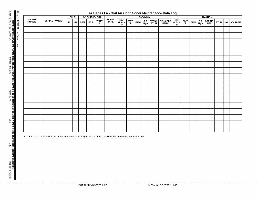
E
2==
7o7"C_
(1)
==
o_"
F;
o
(n
=;.
c
m
O
_=_"
03
c)
o
?
MODELNUMBER SERIAL NUMBER
QTY
RH LH
42 Series Fan Coil Air Conditioner Maintenance Data LogFAN AND MOTOR COOLING
FILTER EAT E T PD TOTAL SENSIBLE EAT
CFM ESP WATTs TYPE db/WboF W GPM H20 BTUH BTUH db/WboFGPM
HEATING
PD STEAM
H20 PSI
NOTE: Indicate repairs made, refrigerant added or removed (include amounts), field controls and valve packages added.
BTUH kW VOLTAGE
CUT ALONG DOTTED LINE CUT ALONG DOTTED LINE
Related Documents