NO.:ZM-SMS-05-10
Address: Building A, 4th Floor, Donghua Industrial Park, Sanwei Section, Bao'an
Road, Bao'an, Shenzhen, China
Telephone:0755-29929955 29929956 Fax:0755-29929953
Http://www.szzhuomao.com E-mail:[email protected]
深圳市卓茂科技有限公司 SHENZHEN ZHUOMAO TECHNOLOGY CO.,LTD.
BGA Rework Station ZM-R5830 Manual

- 1 -
Preface
Shenzhen ZhuoMao Technology Co., Ltd. is a high-tech enterprise involved in
research, development, production and marketing. Since its establishment, with
strong technical force, faithful business philosophy, a sound sales network,
comprehensive and thoughtful after-sales service, through the absorption and the
introduction of foreign advanced technology, we improved ourselves and won
customers trust & supports in the field of BGA rework systems and peripheral
auxiliary equipment.
Company's product are sold in most cities in China and exported to Japan, South
Korea, North Africa, Vietnam, Southeast Asia, the Middle East, Europe and the
United States etc. We got a strong vitality and higher visibility in the same industry.
Our company will continue adhering to the idea of "profession, innovation and
integrity", to provide our customers with more efficient high-quality and convenient
services! Your smile is always Zhuomao’s constant pursuit.
● Thank you so much for choosing BGA rework station ZM-R5830 of
Shenzhen ZhuoMao Technology Co., Ltd.
● Before you operate the machine, please read the manual book carefully to
make sure of the safety and Superior performance of the machine.
● As technology continues to update, Zhuo Mao Technology Co., Ltd. has the
right to modify specifications of the product before notice.
● Please take care of the accessories of the machine.
●If you have any doubt and special requirements of this equipment, you may
contact with our company at any time.
● The Company reserves the final right to interpret the Manual.
- 2 -
Contents
Terms Pages
1st 、 Introduction Features ……………………………………… 3
2nd 、installation ……………………………………………… 4
3rd 、Product specifications and technical parameters …………… 5
4th 、Introduce of the main structure …………………………… 5
5th 、procedures Installation and operation ………………………… 7
6th 、use of external galvanic …………………………………… 29
7th 、Reballing process ……………………………………… 35
8th 、Equipment repair and maintenance …………………………… 37
9th 、precautions ……………………………………… 40
Normal BGA welding and disordering parameters ………………… 42

- 3 -
1st 、Features of ZM-R5830
1、Adopt liner slide which makes X、Y、Z axis all can do precision adjustment or fast
positioning, with high positioning accuracy and fast maneuverability.
2、high definition touch screen , PCL control, can save multiple groups profile,
password protection and modify function, and can save multiple groups profile,
equipped with instant temperature curve analysis function.
3、There are 3 independent heating areas from top to bottom. The 1st and 2nd are
hot-air heaters, the 3rd is IR preheating, temperature controlled within ±3 °. Top
heater can be adjusted freely, second heater can be adjusted up and down, and top and
bottom temperature can control many groups and sections of temperature parameters
at the same time. The third IR heater can be adjusted the power consumption.
4、Offer all kinds of hot-air nozzle, it can rotate 360°.With magnet, easy to install
and change, customized is available. Bottom IR heater ensure an even heat for PCB
board.
5 、Choose imported high-precision K-type thermocouple, closed loop control and
automatic temperature compensation system, combined PLC module for the precision
control of temperature.
6. Use a V-groove equipped with a flexible fixture for PCB positioning to protect the
PCB from deformation when heated or cooled, and it can rework for any BGA
package size.
7、powerful cross-flow fan rapidly cool the PCB board to improve efficiency. Also
built-in vacuum pump and external vacuum suction pen, pick up the chips rapidly.
- 4 -
2nd 、Installation
1、Be away from flammable, explosive, corrosive gas or liquid.
2、Avoid damp places, the air humidity is less than 90%.
3、Temperature -10 ℃ ~ 40 ℃, avoid direct sunlight, prolonged sun exposure.
4、No dust, fibers and metal particles floating in the operational environment.
5、The place of installation needs to be flat, solid, no vibration.
6、Place heavy objects on the body are strictly prohibited.
7、Avoid the affection of direct airflow, such as air-conditioners, heaters or fans.
8、The back of rework station should be reserved 30CM for heat dissipation.
9、The placing table (900 × 900 mm) be flat, the relative level of a height 750 ~ 850
mm.
10、Distribute wiring must be handled by a qualified professional technician, the main
line is 1.5 square feet. Equipment must be well grounded.
11、Switch off the power after use, Power must be disabled if a long-term no need.
3rd 、Specifications
1、Power supply : 220V±10% VAC 50/60Hz
2、Power consumption: 4.5KW Max
3、Heater power: Top heater: 0.8KW; bottom heater: 1.2KW; IR: 2.4KW
4、Electric material: PLC programmable controller + Large-screen TFT Touch
Screen+ high precision intelligent temperature control module

- 5 -
5、Temperature control: K-type closed-loop thermocouple, top and bottom heating
independently, temperature error±3℃
6、Positioning: V-groove fixture for PCB positioning
7、PCB size: 355×335 mm Max 50×50 mm Min
8、Machine dimension:535×650×600 mm
9、Weight:34kg
10、Machine color:Black
4th 、main structure description (1)、structure introduction
(2)Function Introduction
item name function Use method
1 Y-axis adjust Adjust the top heater at Y Right-back,
left-forward
2 Z-axis adjust Adjust the top heater at Z Right-up,left-down
3 Top heater Solder the BGA Adjust by Z-axis
4 LED light
5 Temperature block
6 PCB Pallet Hold up the PCB board
7 Button on the right
side of heating plate
switch on the right heating
board
8 Power switch power On / off the rework
station
9 Start button Start the machine heating

- 6 -
10 Cross-flow fan Cool the PCB board
11 Top nozzle ensure the hot air focuse on the
BGA
a suitable position to
BGA
12 Support the slide bar Tighten the screws to hold PCB
board
13 Bottom nozzle ensure the hot air focuse on the
PCB board
14 PCB Article support adjust and support the PCB board
not to distort
To adjust the height of
stud
15 locknut Fixed pallet
16 Button on the left
side of heating plate switch on the left heating board
17 Lighting button Turn on the light
18 sensor External galvanic, measure the
actual temperature
19 Touch screen Set the temperaturel parameters
to control the machine
20 USB Communication with the external
memory
5th 、Program setting and operating instructions
(1) “Setting screen” operation
1. Turn on the power supply, and then the touch screen will show boot screen (picture
1), then touch “SET UP”, it will show password input dialog box (the initial
password is 8888). (Picture 2)
Pic 1 Pic 2
2. Input the password and then press the ENT button, it will show debugging curve
screen (picture 3)

- 7 -
figure3 Temperature setting curve screen
Introduction of Temperature setting curve screen
Top temperature: it shows the internal galvanic actual temperature of the top hot-air
heater (red curve)
Bottom temperature: it shows the internal galvanic actual temperature of the bottom
hot-air heater (yellow curve)
Top setting: it shows the setting temperature of top hot-air heater
Bottom setting: it shows the setting temperature of top hot-air heater
Time: the time of heating
IR temperature: it shows the internal galvanic actual temperature of the bottom IR
heater (green curve)
IR setting: it shows the setting temperature of IR heating plate
Outer measured temperature: shows the current Outer measured temperature: .
Run time: shows the time of the whole process.
Date: show the curren time.
BGA name: Shows the profile which is working now.

- 8 -
Start: trigger button. Click it, and then the system will start heating.
Stop: trigger button. Click it, and then the system will stop heating.
Cooling manual: cooling system manual or auto exchange button, to control the
change of cooling system.(Note: when heating, it will not allow the cooling system
work. So when you click this button during heating, it will not work.)
Cooling: change button of manual control of motion/stop of cross flow fan.
Vacuum: change button of manual control of motion/stop of vacuum sucker,
Vacuum manual:the button for manual control of the vacuum system, to control the
sucker manually.
Curve analysis: screen change button, click it enter “curve analysis screen”.
Temperature setting: screen change button, click it enter: “temperature setting
screen”.
Same screen to U disk: button for connect with USB, when insert External storage
devices, click this button, then the current screen will be stored in the devices. (the
format is BMP)
Back: screen back button, back to boot screen.
(Note: the curve will be shown from the start of heating to the end, and it will be
saved until next start, and then it will show the new current temperature curve.)
3、Click “temperature setting”button(picture 3),it will enter “temperature setting
screen”.(picture 4)

- 9 -
figure4 temperature parameters setting screen
4、Introduction for temperature parameters setting screen:
Top hot air temperature: top heater temperature enter window, you can set 8 sections,
if do not need to use so many sections, then you can set 0 to the end.
Top hot air time: top heater setting temperature section time enter window,if do not
use, then you can set to 0.
Top hot-air slope: the speed of the temperature increase, the reference is 3, the unit is
℃/S。
Bottom hot air temperature: bottom heater temperature enter window, you can set 8
sections, if do not need to use so many sections, then you can set 0 to the end.
Bottom hot air time: bottom heater setting temperature section time enter window.
Bottom hot-air slope: the speed of the temperature increase, the reference is 3, the
unit is ℃/S。
IR temperature: IR heating plate setting temperature enter window, you had better do
not set many segments.
IR time: IR heating time, it is better longer than the total time of top heater.
IR slope: the speed of IR heating temperature increase.
- 10 -
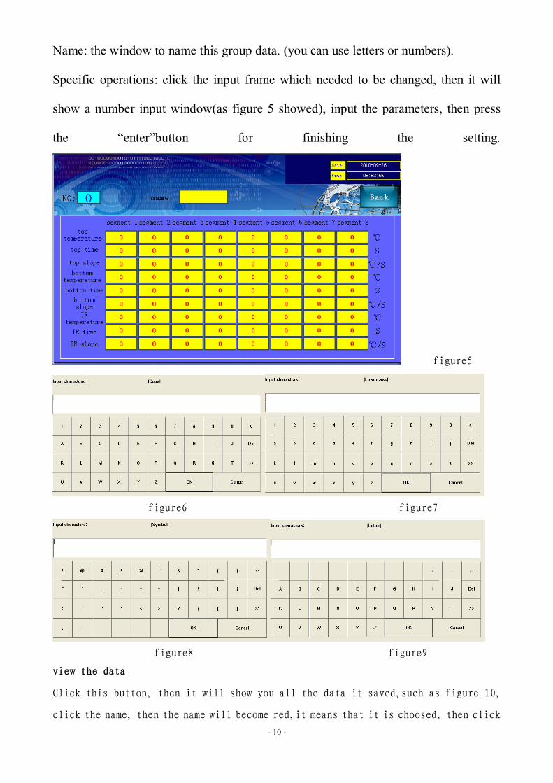
Name: the window to name this group data. (you can use letters or numbers).
Specific operations: click the input frame which needed to be changed, then it will
show a number input window(as figure 5 showed), input the parameters, then press
the “enter”button for finishing the setting.
figure5
figure6 figure7
figure8 figure9
view the data
Click this button, then it will show you all the data it saved,such as figure 10,
click the name, then the name will become red,it means that it is choosed, then click

- 11 -
the LOAD button, then it will show you all the information of this group.
figure10
Save to database: when you finish the parameters setting, then click
this button, then it will be save to database.
2)Groups setting: (This data is the group number.)
(Picture 11) click “Group”, it will show picture 12, then input the numbers (1-50),
named it (this system can save 50 groups), such as picture 14, set it as group 2, and
click ENT for confirmation.
Use the data: click it, it will show you figure15, the data is now which you will use.
Delete the data: delete all the data which you can see now.
Back: screen back button, back to curve screen.
- 12 -
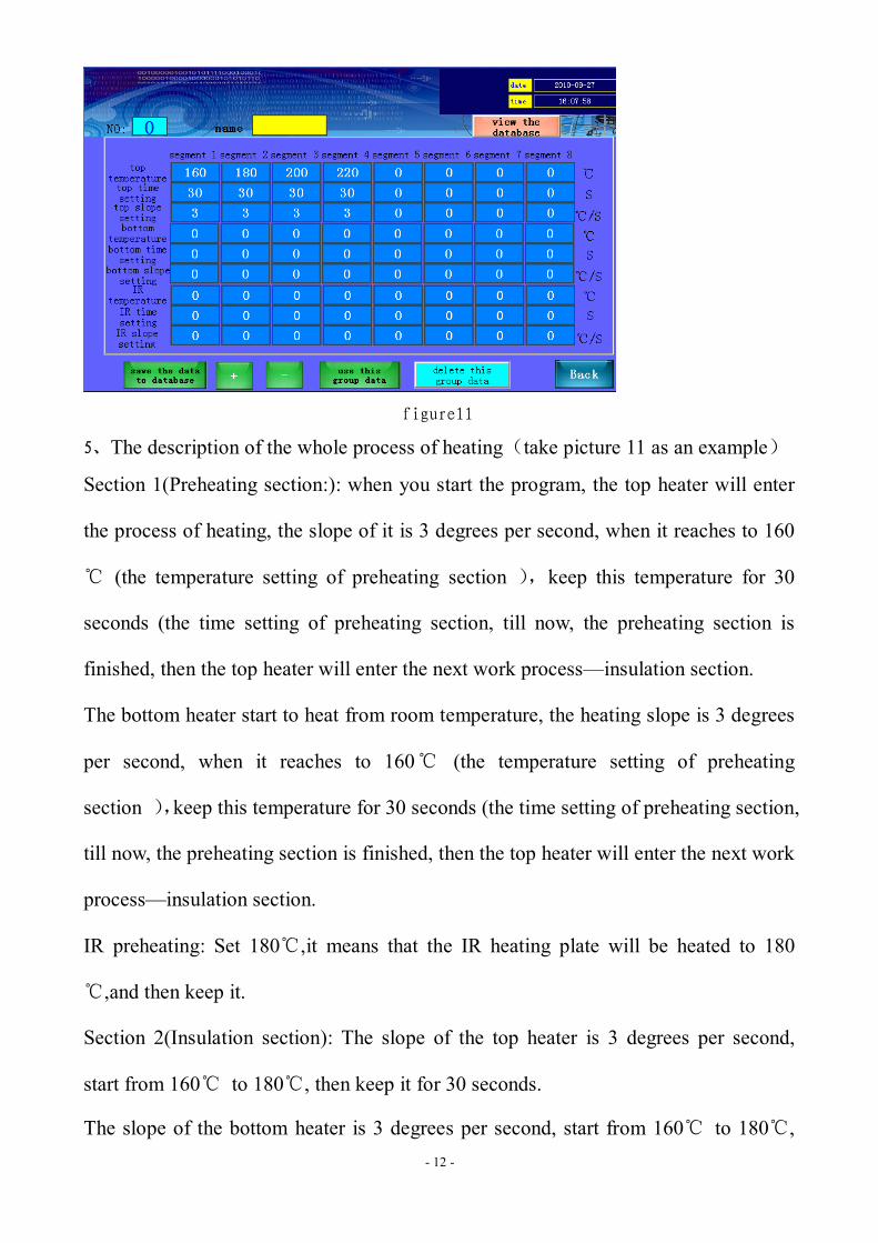
figure11
5、The description of the whole process of heating(take picture 11 as an example)
Section 1(Preheating section:): when you start the program, the top heater will enter
the process of heating, the slope of it is 3 degrees per second, when it reaches to 160
℃ (the temperature setting of preheating section ),keep this temperature for 30
seconds (the time setting of preheating section, till now, the preheating section is
finished, then the top heater will enter the next work process—insulation section.
The bottom heater start to heat from room temperature, the heating slope is 3 degrees
per second, when it reaches to 160℃ (the temperature setting of preheating
section ),keep this temperature for 30 seconds (the time setting of preheating section,
till now, the preheating section is finished, then the top heater will enter the next work
process—insulation section.
IR preheating: Set 180℃,it means that the IR heating plate will be heated to 180
℃,and then keep it.
Section 2(Insulation section): The slope of the top heater is 3 degrees per second,
start from 160℃ to 180℃, then keep it for 30 seconds.
The slope of the bottom heater is 3 degrees per second, start from 160℃ to 180℃,

- 13 -
then keep it for 30 seconds.
Section 3(Heating section): The slope of the top heater is 3 degrees per second, start
from 180℃ to 200℃, then keep it for 30 seconds.
The slope of the bottom heater is 3 degrees per second, start from 180℃ to 200℃,
then keep it for 30 seconds.
Section 4、section 5 and cooling section are same as above.
The process of actual temperature control of this system can be less than the
maximum control sections (8 sections). During the heating process, if you do not
need to use the control section, then you can set 0 to close it.
(2)“OPERATION”
1. Back to the boot screen, (Figure12); click “OPERATION”, (Figure13), then it will
show operation curve screen.
figure12 Boot screen figure13 Operating curve screen
figure14 figure15
Note: the operation of “set up”and “operate”is almost same, the differnce is as

- 14 -
following:
“set up”there is limit for user(need password),You can set up and change any
parameters.
“operate”There is no limit for user(do not need password), you can not set up and
change any parameters.
figure12 figure13
6th 、The use of external measuring galvanic
1、Function
(1)、More accurate to measure the actual temperature of the part to be heated during
the welding process.
(2)、It is easy to move, so that it can be convenient to measure the temperature of
the different parts of the welded components during the heating process.
(3)、After installing galvanic correctly, it will display the galvanic current
measurement temperature in the touch-screen outside the measured
temperature curve screen "measured" column.
2、Installation
(1)、Check the galvanic lines, whether there are disconnected phenomena or not.
(2)、Insert the galvanic Plug into the "outer galvanic Socket” on the control panel
according to the positive and negative mark.

- 15 -
(3)、After GALVANIC installed correctly, click "analysis" button on the touch screen,
switch to "curve analysis" screen, the corresponding galvanic current temperature
will be displayed on the touch screen.
3、Measurement
(1)、PCB board will be installed on the rework station, with the galvanic fixed on the
PCB board using foil stickers. (As shown in Figure 29)
(2)、Adjust the height of the probe with the probe galvanic head located in the top
1-2mm of the test site (as shown in Figure 30)
Figure29 Figure30
3、Adjust the related mechanical adjustment knob, so that the heating part just
below the hot-air tube. (As shown in Figure 30)
4、Adjust the up and down adjustment knob of the hot-air head to make the
distance between the edge of PCB board side and the hot-air head is
3-5mm.
5、Implementation of the welding / disordering process, that is to start the upper
and lower heater.
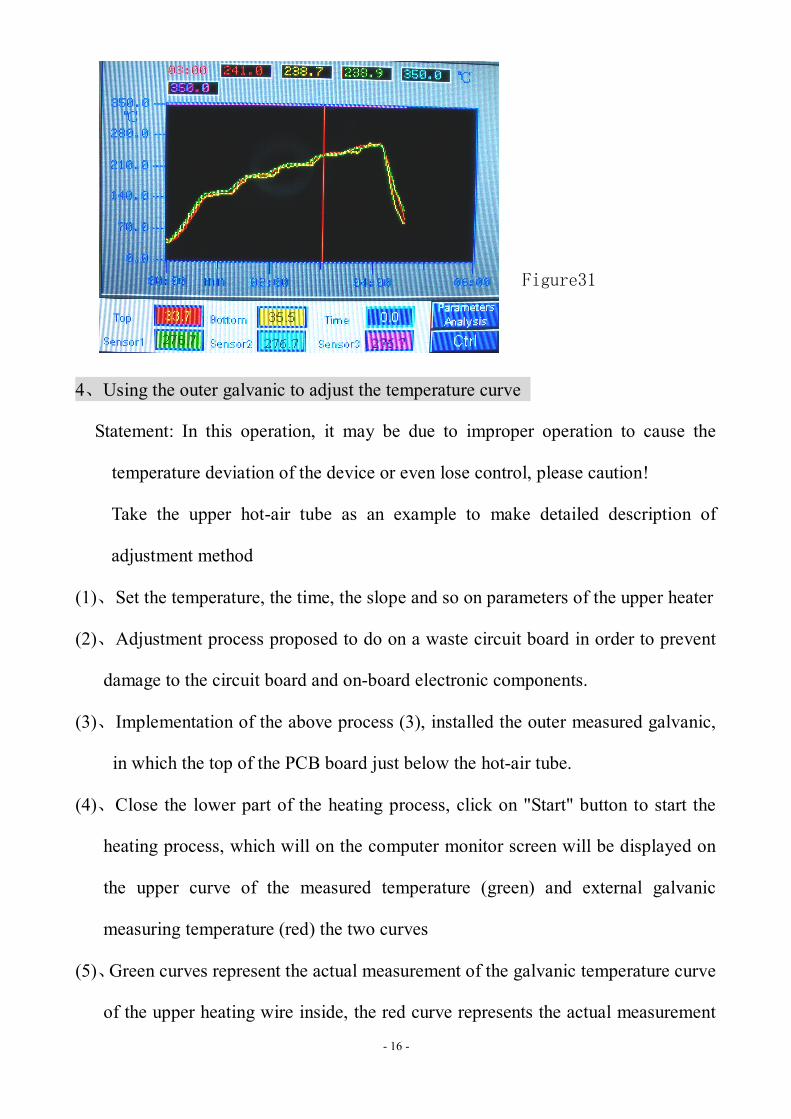
6、Then it will shows the red curve on the computer monitor screen (picture
31),that is the actual measurement temperature of the external galvanic
curve.
- 16 -
Figure31
4、Using the outer galvanic to adjust the temperature curve
Statement: In this operation, it may be due to improper operation to cause the
temperature deviation of the device or even lose control, please caution!
Take the upper hot-air tube as an example to make detailed description of
adjustment method
(1)、Set the temperature, the time, the slope and so on parameters of the upper heater
(2)、Adjustment process proposed to do on a waste circuit board in order to prevent
damage to the circuit board and on-board electronic components.
(3)、Implementation of the above process (3), installed the outer measured galvanic,
in which the top of the PCB board just below the hot-air tube.
(4)、Close the lower part of the heating process, click on "Start" button to start the
heating process, which will on the computer monitor screen will be displayed on
the upper curve of the measured temperature (green) and external galvanic
measuring temperature (red) the two curves
(5)、Green curves represent the actual measurement of the galvanic temperature curve
of the upper heating wire inside, the red curve represents the actual measurement

- 17 -
of the galvanic temperature outside. the smaller the gap between the green curve
and red curve, the closer between the actual temperature and set temperature of
the heating parts, more standard of the upper heating process; On the contrary, the
greater the gap between the two curves, the greater the actual temperature deviate
from the set temperature, the more non-standard of the upper part during the
heating process.
6、If the deviation between the two curves is too much, you should make the
appropriate adjustments
7、The specific adjustment method is as follows, because of the impact of the system
processes and the environmental, deviations in the objective is inevitable. If the
temperature deviation does not affect the normal welding and desordering,
non-professionals should avoid the following corrective actions!
A If the outer galvanic curve (red) lower than the upper one (green), adjust the
internal hairdryer galvanic probe upward;
B If the outer galvanic curve (red) higher than the upper one(green), adjust the
internal hairdryer galvanic probe downward;
C Adjustment must be small, try to control the amplitude of accommodation in
1mm or less;
D Repeated several adjustments;
E During adjustment process, the heated of galvanic probe is strictly prohibited
from contacting with any objects, so as not to affect the accuracy of measuring
temperature;
F After temperature adjustment, you should fix the probe, to avoid the probe
vibration measurement of the temperature of the equipment

- 18 -
G The method of the adjustment applies only to the two parallel curves in a
smooth uniform deviation, and it is invalid to the temperature which is from
top to bottom jitter free-laws regulating!
H The upper part of the internal galvanic Duct location: Remove the upper
heater nozzle, at a distance of 2-3cm at the edge wind-cone .
I operating the standard procedure to avoid the high-temperature burns!
8、There is no booster thermocouple temperature curve on the bottom of the computer
screen, so you have to adjust the process of the lower part of the heaters by
visual.
9、fixed the galvanic line with foil stickers on the bottom of PCB board (as opposed
to the upper heater set back on the PCB board), so that the probe of the booster
thermocouple is located just 2mm above the mouth of the bottom hot-air nozzle,
and adjust the mechanical parts, make the upper hot-air nozzle deviate from the
heated parts to avoid cold air affect the temperature of the heated parts.
10、The caution is same as the top heater.
11、The methods of adjustment:
A If the outer temperature is lower than the bottom, you should adjust the lower
internal galvanic probe downward.
B If the outer temperature is higher than the bottom; you should adjust the lower
internal galvanic probe upward.
7th 、Reballing Process
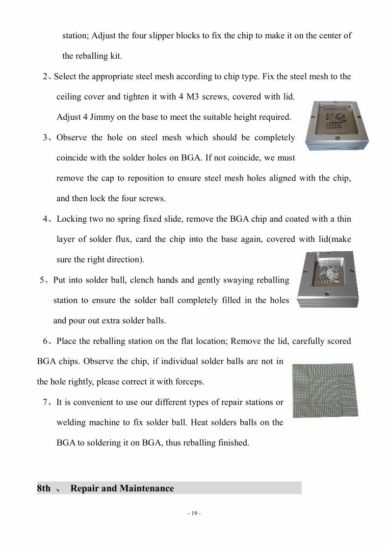
1、Fix the BGA chip on the base of our universal reballing
- 19 -
station; Adjust the four slipper blocks to fix the chip to make it on the center of
the reballing kit.
2、Select the appropriate steel mesh according to chip type. Fix the steel mesh to the
ceiling cover and tighten it with 4 M3 screws, covered with lid.
Adjust 4 Jimmy on the base to meet the suitable height required.
3、Observe the hole on steel mesh which should be completely
coincide with the solder holes on BGA. If not coincide, we must
remove the cap to reposition to ensure steel mesh holes aligned with the chip,
and then lock the four screws.
4、Locking two no spring fixed slide, remove the BGA chip and coated with a thin
layer of solder flux, card the chip into the base again, covered with lid(make
sure the right direction).
5、Put into solder ball, clench hands and gently swaying reballing
station to ensure the solder ball completely filled in the holes
and pour out extra solder balls.
6、Place the reballing station on the flat location; Remove the lid, carefully scored
BGA chips. Observe the chip, if individual solder balls are not in
the hole rightly, please correct it with forceps.
7、It is convenient to use our different types of repair stations or
welding machine to fix solder ball. Heat solders balls on the
BGA to soldering it on BGA, thus reballing finished.
8th 、 Repair and Maintenance

- 20 -
(1) Upper heater:(Pictured)
t o p n o z z le
A lu m in u m u p p e r h e a d
h e a t in g w i r e
t o p f ix e rp la s t ic c o n n e c to rh e a t in g w i r e f ix e r
f a n
h ig h - t e m p e r a tu r e in s u la t in g p a p e r
c o v e r
1. First switch off, make the top heater totally cool down; 2. the replace of fan:Remove the heater cover, and remove the insulation fiber block, then you can replace the fan.
3. The replacement of heating wire
Remove the heater cover 、 fan, remove the upper fixed block, Plastic
Connector ,heater fixer one by one, and then take out the hot wire. Then it can be
replaced.(as pictured)
Note: When you change the heating wire; it must be wrapped by High-temperature
insulating paper.
(2) Replacement of bottom heater(as pictured)

- 21 -
02
03
06
07
08
09
04
05
10
01
01 body 02 Heating Duct 03 Heater
04 Heating wire fixture 05 mounting deck 06 Plastic Connector
07 Fan mounts 08 Fan bracket bolts 09 fan
10 fan Bolt
Replacement of bottom heater:
1)、Remove the fixing screw, turn back the machine till the heaters appear..
2)、Demolition of fans, fan holder, plastic connector and fan wire fixture, take out the
hot wire. Then you can replace the heating wire,
Note: When you change the heating wire; it must be wrapped by High-temperature
insulating paper.
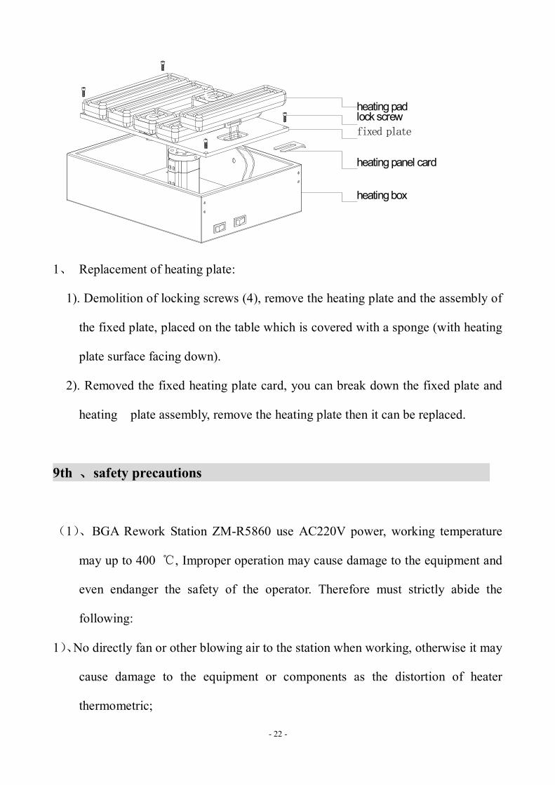
(3)、The bottom heating panel (pictured)
- 22 -
heating padlock screw
heating box
heating panel card
fixed plate
1、 Replacement of heating plate:
1). Demolition of locking screws (4), remove the heating plate and the assembly of
the fixed plate, placed on the table which is covered with a sponge (with heating
plate surface facing down).
2). Removed the fixed heating plate card, you can break down the fixed plate and
heating plate assembly, remove the heating plate then it can be replaced.
9th 、safety precautions
(1)、BGA Rework Station ZM-R5860 use AC220V power, working temperature
may up to 400 ℃, Improper operation may cause damage to the equipment and
even endanger the safety of the operator. Therefore must strictly abide the
following:
1)、No directly fan or other blowing air to the station when working, otherwise it may
cause damage to the equipment or components as the distortion of heater
thermometric;

- 23 -
2)、prohibited flammable gases or liquid around the machine; After booting,
forbidden combustibles touch high temperature district and peripheral metal parts,
otherwise it will easily cause fire or explosion;
3)、 To avoid high temperature scald, forbidden touching high temperature fever
zone during working. PCB board still warm when completed, operation process
should take necessary protective measures;
4)、PCB board should be placed on V type support shelves and used slider pairs to
support PCB board in the centre; e. Metal or angular and sharp objects are
avoided on touch screen surface;
5)、upper and lower heater inlet must not be blocked, otherwise heating wire will be
damaged;
6)、After work, please guarantee natural cooling for 5 minutes, then Switch off;
7)、if metal objects or liquid fall into rework station during working, you should
power off immediately, unplug power plug, until it cooled, then eradicate litter
and dirt; it will be influenced if grease on the heating panels and accompanied
by odor when rebooting. Please keep the machine clean and timely maintenance.
8)、when appears abnormal warming or smoke on the machine, immediately
disconnect power and notify technical service personnel to repair it; Remove the
connections data line between computer and devices, hold the plug to unplug the
data line, to avoid damaging internal connection.
(2)if it belongs to one of the following situations, and other damage caused by them;
It will not be in the Company guarantee scope!
1、Failing uses the method in manual to operate in wrong conditions or environmental
operation;;

- 24 -
2、The Company product outside reasons;
3、Not the transformation and maintenance of the company;
4、not accordance to the method stipulated when using the products ;
5、unpredictable situation that the company scientific technical level not reached;
6、Natural disasters or man-made destruction of non-responsibility of the company
premises.
Normal BGA welding and disordering parameters(for reference)
1、The temperature curve of lead welding
41*41 the temperature setting of the BGA welding:
38*38 the temperature setting of the BGA welding:
31*31 the temperature setting of the BGA welding:
preheating insulation heating welding1 welding2 cooling
upper 160 185 210 235 240 225
time 30 30 35 40 20 15
bottom 160 185 210 235 240 225
time 30 30 35 40 20 15
slope 3.0 3.0 3.0 3.0 3.0 3.0
IR 180
preheating insulation heating welding1 welding2 cooling
upper 160 185 210 225 235 215
time 30 30 35 40 20 15
bottom 160 185 210 225 235 215
time 30 30 35 40 20 15
slope 3.0 3.0 3.0 3.0 3.0 3.0
IR 185
- 25 -
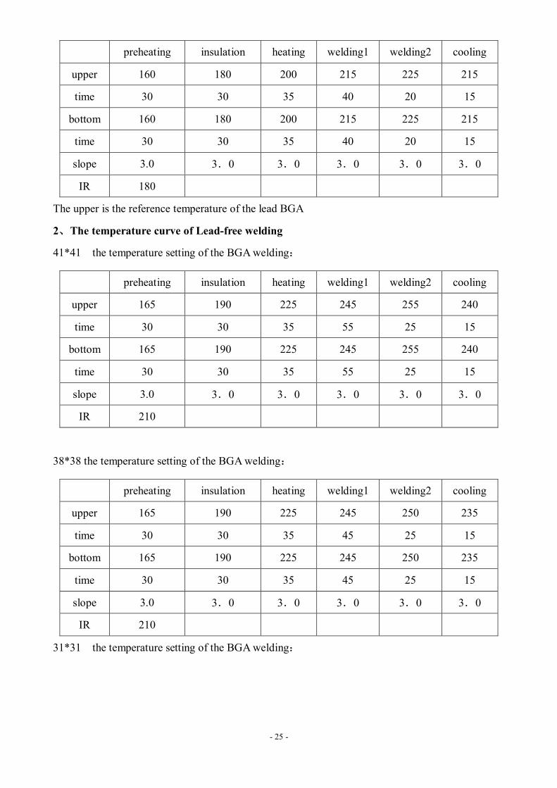
The upper is the reference temperature of the lead BGA
2、The temperature curve of Lead-free welding
41*41 the temperature setting of the BGA welding:
38*38 the temperature setting of the BGA welding:
31*31 the temperature setting of the BGA welding:
preheating insulation heating welding1 welding2 cooling
upper 160 180 200 215 225 215
time 30 30 35 40 20 15
bottom 160 180 200 215 225 215
time 30 30 35 40 20 15
slope 3.0 3.0 3.0 3.0 3.0 3.0
IR 180
preheating insulation heating welding1 welding2 cooling
upper 165 190 225 245 255 240
time 30 30 35 55 25 15
bottom 165 190 225 245 255 240
time 30 30 35 55 25 15
slope 3.0 3.0 3.0 3.0 3.0 3.0
IR 210
preheating insulation heating welding1 welding2 cooling
upper 165 190 225 245 250 235
time 30 30 35 45 25 15
bottom 165 190 225 245 250 235
time 30 30 35 45 25 15
slope 3.0 3.0 3.0 3.0 3.0 3.0
IR 210

- 26 -
The upper is the reference temperature of the lead-free BGA
Such as set 0 when the demolition of the cooling section of BGA.
preheating insulation heating welding1 welding2 cooling
upper 165 190 220 240 245 235
time 30 30 35 40 20 15
bottom 165 190 220 240 245 235
time 30 30 35 40 20 15
slope 3.0 3.0 3.0 3.0 3.0 3.0
IR 210