Decoupling Naming from Routing via Virtual Id ROuting
A Scalable, Robust and Namespace Independent Routing Architecture for Future Networks
Zhi-Li Zhang,University of Minnesota-Twin Cities
Joint work with my students:Sourabh Jain (now at Cisco), Yingying Chen,
Saurabh Jain
2
Outline
Introduction and Motivation Current Trends Challenges Recent Proposals
VIRO Virtual ID layer Routing Table Construction vid lookup & Forwarding
Evaluation Simulation based Setup Real Implementation and Prototyping
Summary and On-going work
3
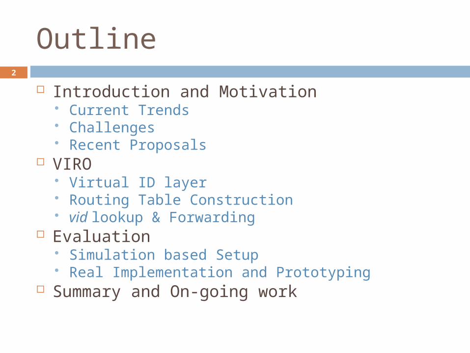
Current Trends and Future Networks
Large number of mobile users and
systems
Large number of smart appliances
High bandwidth core data centers &
clouds Diverse edges
mobility intermittent
connectivity
Heterogeneous technologies
More and more virtualizations:
virtual servers, clients
virtual networks
Internet(or Future Networking Substrate)
Internet(or Future Networking Substrate)
Home users
Banking &
e-commerce
Smart phones,
smart pads,
etc.
POTS
VoIP
Multimedia
StreamingGames
surveillance
& Security
IP TV
Web, emails
& cloud services
Smart meters,
smart grid,
sensors, etc.
Social networks
4
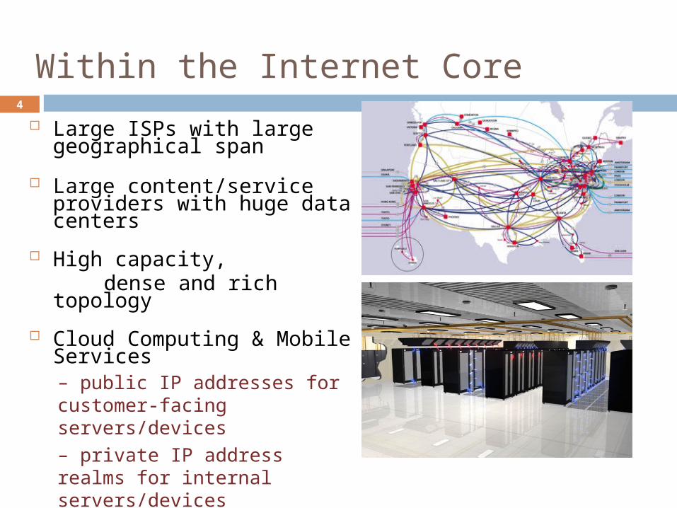
Within the Internet Core
Large ISPs with large geographical span
Large content/service providers with huge data centers
High capacity, dense and rich topology
Cloud Computing & Mobile Services
– public IP addresses for customer-facing servers/devices– private IP address realms for internal servers/devices
5
Challenges posed by These Trends
Scalability: capability to connect tens of thousands or more users and devices routing table size, constrained by router memory, lookup speed
Mobility: hosts are more mobile, “virtual servers” are also mobile need to separate location (“addressing”) and identity (“naming”)
Availability & Reliability: must be resilient to failures need to be “proactive” instead of reactive need to localize effect of failures
Manageability (& Security): ease of deployment, “plug-&-play” need to minimize manual configuration self-configure, self-organize, while ensuring security and trust
…….

6
How Existing Technologies Meet these Challenges?
(Layer-2) Ethernet/Wireless LANs Pluses: plug-&-play,
minimal configuration, better mobility
Minuses: (occasional) data plane
flooding, sub-optimal routing (using spanning tree), not robust to failures
Not scalable to large (& wide-area) networks
(Layer-3) IPv4/IPv6 Pluses:
better data plane scalability, more “optimal” routing, …
Minuses: control plane flooding, global
effect of network failures poor support for mobility difficulty/complexity in
“network renaming” Esp., changing addressing
schemes (IPv4 -> IPv6 transition) requires modifications in routing and other network protocols
7
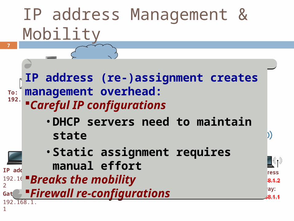
IP address Management & Mobility
Subnet Prefix:
192.168.1.0
Mask:
255.255.255.0
Gateway:
192.168.1.1
Subnet Prefix:
192.168.2.0
Mask:
255.255.255.0
Gateway:
192.168.2.1
Interface IP address: 192.168.1.1
Interface IP address: 192.168.1.1
Interface IP address: 192.168.2.1
Interface IP address: 192.168.2.1
IP address
192.168.1.2
Gateway:
192.168.1.1
To: 192.168.1.2
IP address (re-)assignment creates management overhead:Careful IP configurations
• DHCP servers need to maintain state
• Static assignment requires manual effort
Breaks the mobilityFirewall re-configurations
IP address (re-)assignment creates management overhead:Careful IP configurations
• DHCP servers need to maintain state
• Static assignment requires manual effort
Breaks the mobilityFirewall re-configurations
8
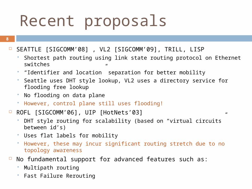
Recent proposals
SEATTLE [SIGCOMM’08] , VL2 [SIGCOMM’09], TRILL, LISP Shortest path routing using link state routing protocol on Ethernet switches “Identifier and location” separation for better mobility Seattle uses DHT style lookup, VL2 uses a directory service for flooding
free lookup No flooding on data plane However, control plane still uses flooding!
ROFL [SIGCOMM’06], UIP [HotNets’03] DHT style routing for scalability (based on “virtual circuits” between id’s) Uses flat labels for mobility However, these may incur significant routing stretch due to no topology
awareness No fundamental support for advanced features such as:
Multipath routing Fast Failure Rerouting
9
Outline
Introduction and Motivation Current Trends Challenges Recent Proposals
VIRO Virtual ID layer Routing Table Construction vid lookup & Forwarding
Evaluation Simulation based Setup Real Implementation and Prototyping
Summary and On-going work
10
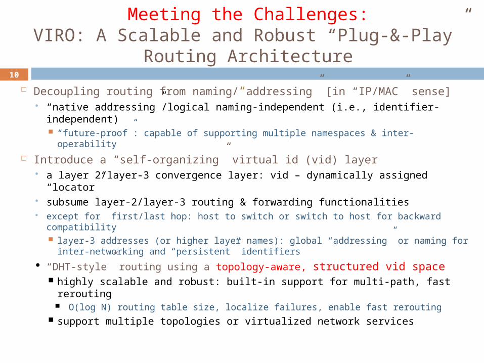
Meeting the Challenges:VIRO: A Scalable and Robust “Plug-&-Play” Routing
Architecture
Decoupling routing from naming/“addressing” [in “IP/MAC” sense] “native addressing”/logical naming-independent (i.e., identifier-
independent) “future-proof”: capable of supporting multiple namespaces & inter-operability
Introduce a “self-organizing” virtual id (vid) layer a layer 2/layer-3 convergence layer: vid – dynamically assigned “locator” subsume layer-2/layer-3 routing & forwarding functionalities except for first/last hop: host to switch or switch to host for backward compatibility
layer-3 addresses (or higher layer names): global “addressing” or naming for inter-networking and “persistent” identifiers
“DHT-style” routing using a topology-aware, structured vid space highly scalable and robust: built-in support for multi-path, fast rerouting
O(log N) routing table size, localize failures, enable fast rerouting support multiple topologies or virtualized network services
11
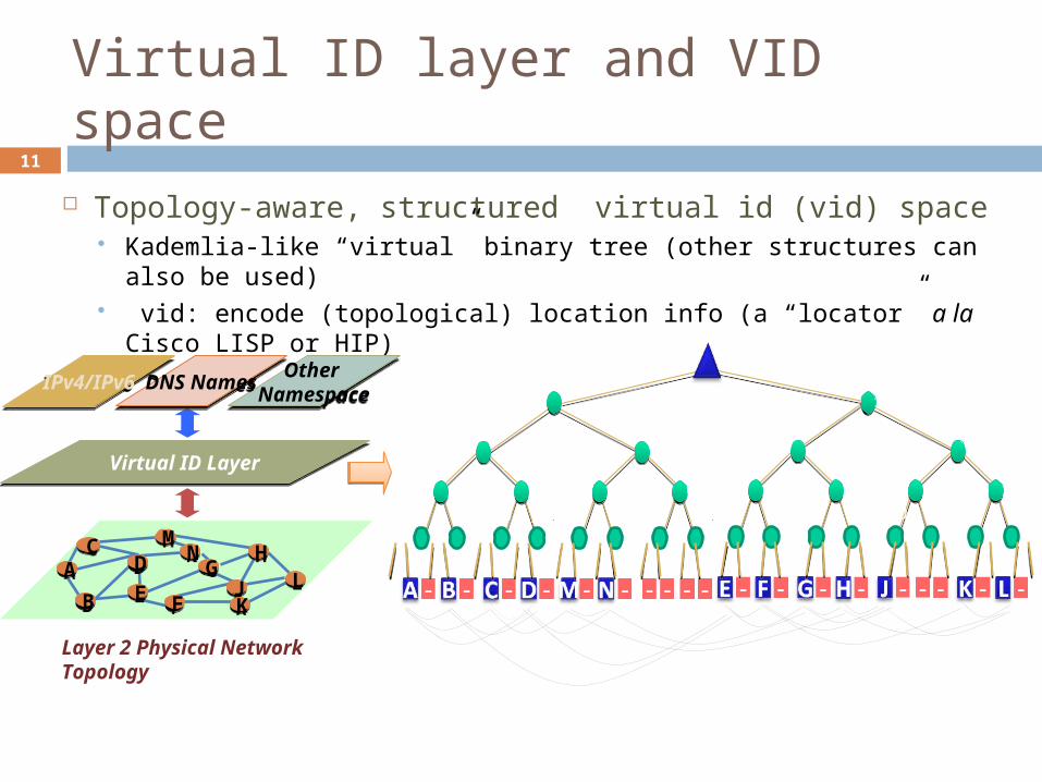
Virtual ID layer and VID space
Topology-aware, structured virtual id (vid) space Kademlia-like “virtual” binary tree (other structures can also be
used) vid: encode (topological) location info (a “locator” a la Cisco
LISP or HIP)
Layer 2 Physical Network Topology
IPv4/IPv6IPv4/IPv6
Virtual ID LayerVirtual ID Layer
Other Namespace
Other NamespaceDNS NamesDNS Names
MMNN HH
GGJJ LLKK
CC
FFEEBB
DDAA1
1
1
1 1
0
0
0 0 011
0
0
1
10
0
0
0
1
1
1
1
1
0 0
1
0
0 1
0 01
1
0 0 0 0 01 1 1 11 1

12
VIRO: Three Core Components
Virtual id space construction and vid assignment Performed at the bootstrap process (i.e., network set up): Once network is set up/vid space is constructed:
a new node (a “VIRO switch”) joins: assigned based on neighbors’ vid’s end-host/device: inherits a vid (prefix) from “host switch” (to which it is
attached), plus a randomly assigned host id; host may be agnostic of its vid
VIRO routing algorithm/protocol: DHT-style, but needs to build end-to-end connectivity/routes
a bottom-up, round-by-round process, no network-wide control flooding O(log N) routing entries per node, N ≈ # of VIRO switches
DHT based name/identifier to address/locator mapping service Data forwarding among VIRO switches using vid only
switch vid host id
L l
13
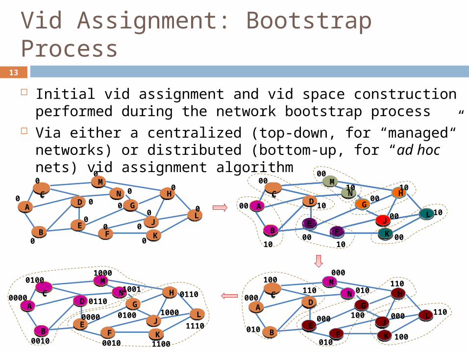
Vid Assignment: Bootstrap Process
Initial vid assignment and vid space construction performed during the network bootstrap process
Via either a centralized (top-down, for “managed” networks) or distributed (bottom-up, for “ad hoc” nets) vid assignment algorithm
0
0MM
NN HH
GG
JJLL
KK
CC
FFEE
BB
DDAA
00
000
00
00 0
00 10
00
10
M
N H
G
JL
K
\
FE
B
DA
MM
NN H
G
JJL
KK
CC
BB
DDAA00
00
10
10 10
00
10
0000
00
010
000
000
MM
NN HH
GG
JJLL
KK
CC
FFEE
BB
DDAA
100110
010
010
000 100
110
110
100
000
0010 0010 1100
MM
NN HH
GG
JJLL
KK
CC
FFEE
BB
DDAA
0000
0100
0110
1000
1001
0000 0100
0110
1110
1000

14
Vid Assignment : Key Properties
1
1
1
1 1
0
0
0 0 011
0
0
1
10
0
0
0
1
1
1
1
1
0 0
1
0
0 1
01
1
0 0 0 0 01 1 1 11 1
00010 10010 11100
MM
NN HH
GG
JJLL
KK
CC
FFEE
BB
DDAA
00000
00100
00110
01000
01001
10000 10100
10110
11110
11000
Key invariant properties:closeness: if two nodes are close in the vid space, then they are also close in the physical topology esp., any two logical neighbors must be directly connected.connectivity: any logical sub-trees must be physically connected.
0
0 00
0
0 0 0 00 00
00
0
1
11
11 1111 111 11 1
15
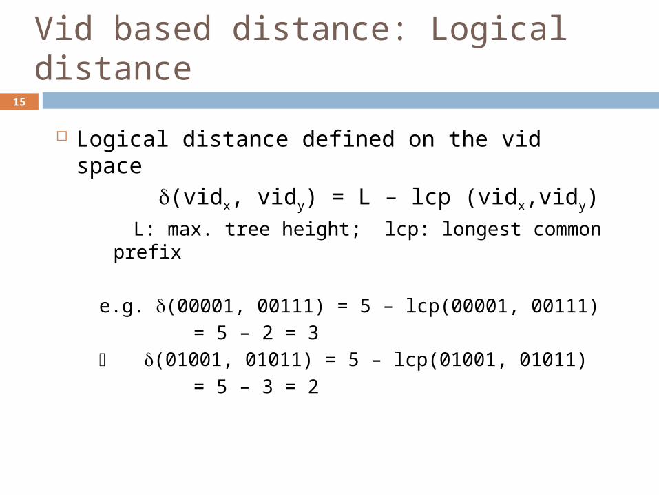
Vid based distance: Logical distance
Logical distance defined on the vid space (vidx, vidy) = L – lcp (vidx,vidy)
L: max. tree height; lcp: longest common prefix
e.g. (00001, 00111) = 5 – lcp(00001, 00111)
= 5 – 2 = 3
(01001, 01011) = 5 – lcp(01001, 01011)
= 5 – 3 = 2
16
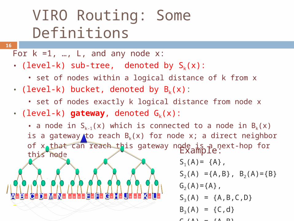
VIRO Routing: Some Definitions
For k =1, …, L, and any node x:• (level-k) sub-tree, denoted by Sk(x):
• set of nodes within a logical distance of k from x
• (level-k) bucket, denoted by Bk(x): • set of nodes exactly k logical distance from node x
• (level-k) gateway, denoted Gk(x):
• a node in Sk-1(x) which is connected to a node in Bk(x) is a gateway to reach Bk(x) for node x; a direct neighbor of x that can reach this gateway node is a next-hop for this node
–
Example: S1(A)= {A},
S2(A) ={A,B}, B2(A)={B}
G2(A)={A},
S3(A) = {A,B,C,D}
B3(A) = {C,d}
G3(A) = {A,B}
1
1
1
1 1
0
0
0 0 011
0
0
1
10
0
0
0
1
1
1
1
1
0 0
1
0
0 1
0 01
1
0 0 0 0 01 1 1 11 1
17
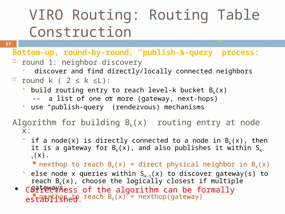
VIRO Routing: Routing Table Construction
Bottom-up, round-by-round, “publish-&-query” process:
round 1: neighbor discovery discover and find directly/locally connected neighbors
round k ( 2 ≤ k ≤L): build routing entry to reach level-k bucket Bk(x)
-- a list of one or more (gateway, next-hops) use “publish-query” (rendezvous) mechanisms
Algorithm for building Bk(x) routing entry at node x: if a node(x) is directly connected to a node in Bk(x), then it is a
gateway for Bk(x), and also publishes it within Sk-1(x). nexthop to reach Bk(x) = direct physical neighbor in Bk(x)
else node x queries within Sk-1(x) to discover gateway(s) to reach Bk(x), choose the logically closest if multiple gateways. nexthop to reach Bk(x) = nexthop(gateway) Correctness of the algorithm can be formally established.
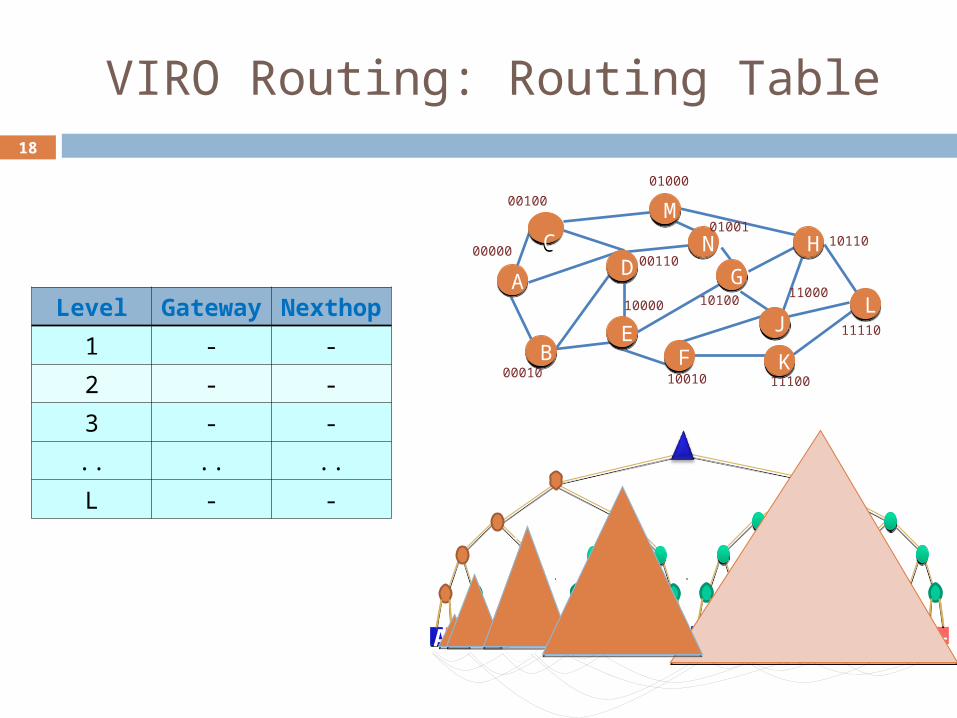
18
VIRO Routing: Routing Table
1
1
1
1 1
0
0
0 0 011
0
0
1
10
0
0
0
1
1
1
1
1
0 0
FFEE HHGGBBAA DDCC NNMM JJ LLKK
1
0
0 1
01
1
0 0 0 0 01 1 1 11 1
00010 10010 11100
MM
NN HH
GG
JJLL
KK
CC
FFEE
BB
DDAA
00000
00100
00110
01000
01001
10000 10100
10110
11110
11000Level Gatew
ay Nextho
p
1 - -
2 - -
3 - -
.. .. ..
L - -

19
VIRO Routing: Packet Forwarding
To forward a packet to a destination node, say, L compute the logical distance to that node Use the nexthop corresponding to the logical distance for
forwarding the packet If no routing entry:
drop the packet
00010 10010 11100
MM
NN HH
GG
JJLL
KK
CC
FFEE
BB
DDAA
00000
00100
00110
01000
01001
10000 10100
10110
11110
11000
Bucket Distan
ce
Gateway
Nexthop
1 - -
2 A B
3 A C,D
4 C C
5 B B
20
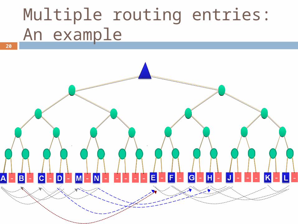
Multiple routing entries: An example
1
1
1
1 1
0
0
0 0 011
0
0
1
10
0
0
0
1
1
1
1
1
00
1
0
0 1
0 01
1
0 0 0 0 01 1 1 11 1
21
Multiple Routing Entries
Learn multiple gateways at each level Default gateway is the one that is logically
closest Use additional gateways for multi-
pathing and fast failure re-routing Requires consistent gateway selection
Otherwise forwarding loops may occur Use appropriate “forwarding directive”
while using alternate gateways
22
pid to vid translation
DHT Style lookup/store mechanism Simple and scalable
A backward compatible approach to work with Ethernet based protocols Re-use ARP (address resolution protocol) to
perform IP to vid mapping Assumes IP address as the pid for the host-
devices Simple modification to ARP will allow any host
namespace to vid mapping
23
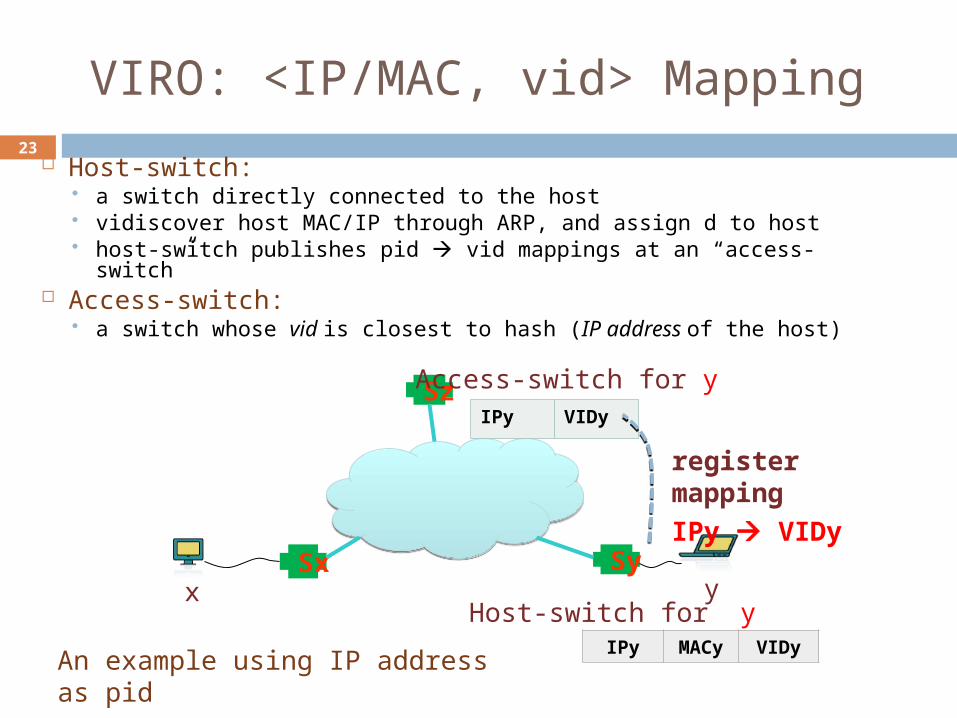
VIRO: <IP/MAC, vid> Mapping
Host-switch: a switch directly connected to the host vidiscover host MAC/IP through ARP, and assign d to host host-switch publishes pid vid mappings at an “access-
switch” Access-switch:
a switch whose vid is closest to hash (IP address of the host)
Sx Sy
Sz
x yHost-switch for y
IPyMAC
yVIDy
IPy VIDy
Access-switch for y
register mappingIPy VIDy
An example using IP address as pid
24
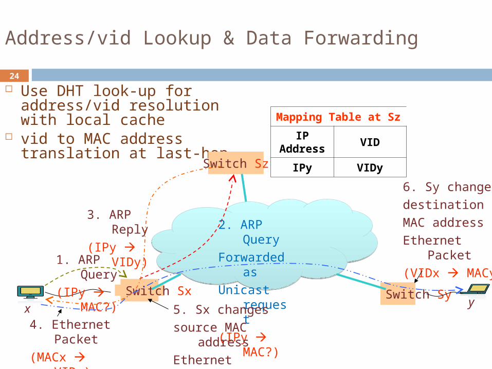
Address/vid Lookup & Data Forwarding
Use DHT look-up for address/vid resolution with local cache
vid to MAC address translation at last-hop
Switch Sx Switch Sy
Switch Sz
x y
1. ARP Query
(IPy MAC?)
2. ARP Query
Forwarded as
Unicast request
(IPy MAC?)
3. ARP Reply
(IPy VIDy)
4. Ethernet Packet
(MACx VIDy)
5. Sx changes source MAC
addressEthernet Packet (VIDx VIDy)
6. Sy changes destination MAC addressEthernet Packet (VIDx MACy)
Mapping Table at Sz
IP Address
VID
IPy VIDy
25
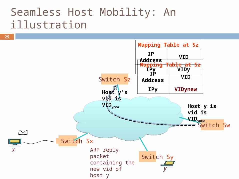
Seamless Host Mobility: An illustration
Switch Sx
Switch Sy
Switch Sz
x
y
Mapping Table at Sz
IP Address
VID
IPy VIDy
Switch Sw
Host y is vid is VIDynew
Host y’s vid is VIDynew
Mapping Table at Sz
IP Address
VID
IPy VIDynew
ARP reply packet containing the new vid of host y
26
Outline
Introduction and Motivation Current Trends Challenges Recent Proposals
VIRO Virtual ID layer Routing Table Construction vid lookup & Forwarding
Evaluation Simulation based Setup Real Implementation and Prototyping
Summary and On-going work

27
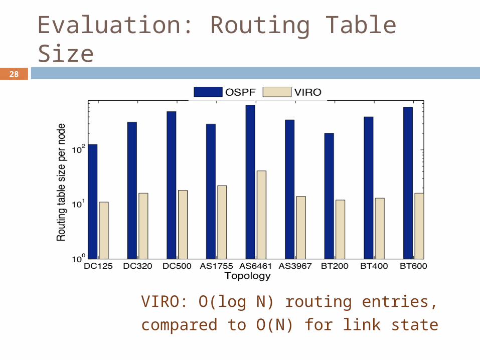
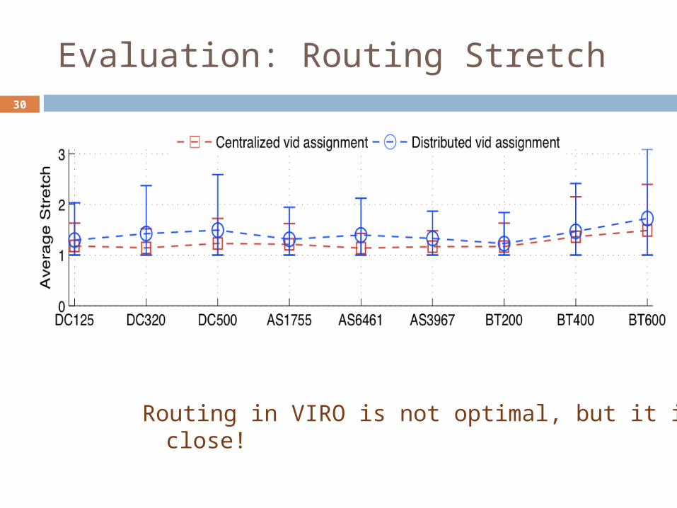
Initial Evaluation using Simulations
Used various AS and data center network topologies VIRO is compared against link-state routing protocol
(e.g., OSPF) Compared routing stretch, routing table size, control
overhead, failure dynamics, etc. Simulation code implemented in JAVA
AS Topologies AS1755(295 nodes, 543 edges)
AS3967(353 nodes, 820 edges)
AS6461(654 nodes, 1332 edges)
Data Center Topologies
DC125(125 nodes, 500 edges)
DC320(320 nodes, 2048 edges)
DC500(500 nodes, 4000 edges)
BRITE Topologies BT200(200 nodes, 790 edges)
BT400(400 nodes, 1590 edges)
BT600(600 nodes, 2390 edges)
28
Evaluation: Routing Table Size
VIRO: O(log N) routing entries, compared to O(N) for link state

29
Evaluation: Control Overhead
Significant reduction in control overhead per node(VIRO-1,2,4 with 1,2 and 4 rendezvous nodes at each level, VIRO-log has log(k) rendezvous nodes at kth level
30
Evaluation: Routing Stretch
Routing in VIRO is not optimal, but it is close!

31
VEIL-Click: An initial prototype Implementation of VIRO/VEIL
architecture using Click Modular Router framework
VEIL-Click enabled switch consists of: A linux machine Multiple network interfaces Click Modular Router VEIL as Click elements

32
Summary
VIRO provides a scalable & robust substrate for future networks No flooding in both data and control planes Back up routing entries for robustness
Support for multiple namespaces Essential for seamless mobility
VIRO can be realized! VEIL (Virtual Ethernet ID Layer) for large-scale layer-2 networks
Backward compatible compatible with current host protocols (such as ARP etc)
Enables (nearly) configuration-free networks Built-in support for Multi-path routing Extensible to support multiple topologies, virtualized network services
Ongoing work: Prototype using Click & OpenFlow switches Extensions to enable multiple ‘virtual’ topologies, management
control plane…

Thanks!
Please visit http://networking.cs.umn.edu/veil for:
o Demo videos, o List of related publications, o Source code!
Or simply search online for “VIRO VEIL”
Thanks!
34
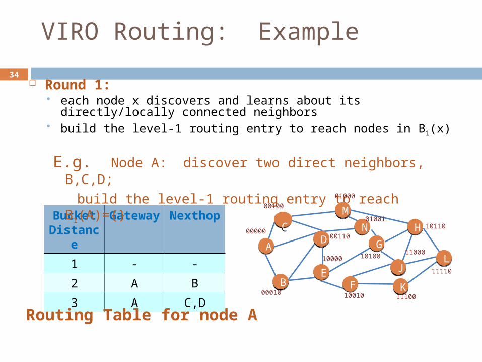
VIRO Routing: Example
Round 1: each node x discovers and learns about its directly/locally
connected neighbors build the level-1 routing entry to reach nodes in B1(x)
Bucket Distan
ce
Gateway
Nexthop
1 - -
2 A B
3 A C,DRouting Table for node A
E.g. Node A: discover two direct neighbors, B,C,D;
build the level-1 routing entry to reach B1(A)={}
00010 10010 11100
MM
NN HH
GG
JJLL
KK
CC
FFEE
BB
DDAA
00000
00100
00110
01000
01001
10000 10100
10110
11110
11000
35
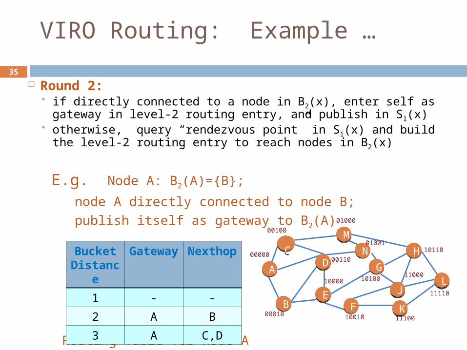
VIRO Routing: Example …
Round 2: if directly connected to a node in B2(x), enter self as
gateway in level-2 routing entry, and publish in S1(x) otherwise, query “rendezvous point” in S1(x) and
build the level-2 routing entry to reach nodes in B2(x)
Routing Table for node A
E.g. Node A: B2(A)={B};
node A directly connected to node B; publish itself as gateway to B2(A)
00010 10010 11100
MM
NN HH
GG
JJLL
KK
CC
FFEE
BB
DDAA
00000
00100
00110
01000
01001
10000 10100
10110
11110
11000
Bucket Distan
ce
Gateway
Nexthop
1 - -
2 A B
3 A C,D

36
VIRO Routing: Example …
Round 3: if directly connected to a node in B3(x), enter self as
gateway in level-3 routing entry, and publish in S2(x) otherwise, query “rendezvous point” in S2(x) and build
the level-2 routing entry to reach nodes in B3(x)
E.g. Node A: B3(A)={C,D};
A publishes edges A->C, A->D to “rendezvous point” in S2(A), say, B;
00010 10010 11100
MM
NN HH
GG
JJLL
KK
CC
FFEE
BB
DDAA
00000
00100
00110
01000
01001
10000 10100
10110
11110
11000
Bucket Distan
ce
Gateway
Nexthop
1 - -
2 A B
3 A C,D
37
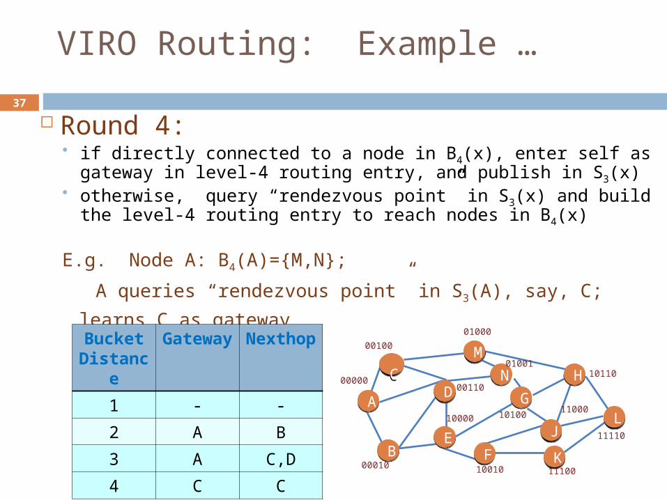
VIRO Routing: Example …
Round 4: if directly connected to a node in B4(x), enter self as
gateway in level-4 routing entry, and publish in S3(x) otherwise, query “rendezvous point” in S3(x) and build
the level-4 routing entry to reach nodes in B4(x)
E.g. Node A: B4(A)={M,N};
A queries “rendezvous point” in S3(A), say, C; learns C as
gateway
00010 10010 11100
MM
NN HH
GG
JJLL
KK
CC
FFEE
BB
DDAA
00000
00100
00110
01000
01001
10000 10100
10110
11110
11000
Bucket Distan
ce
Gateway
Nexthop
1 - -
2 A B
3 A C,D
4 C C
38
VIRO Routing: Example …
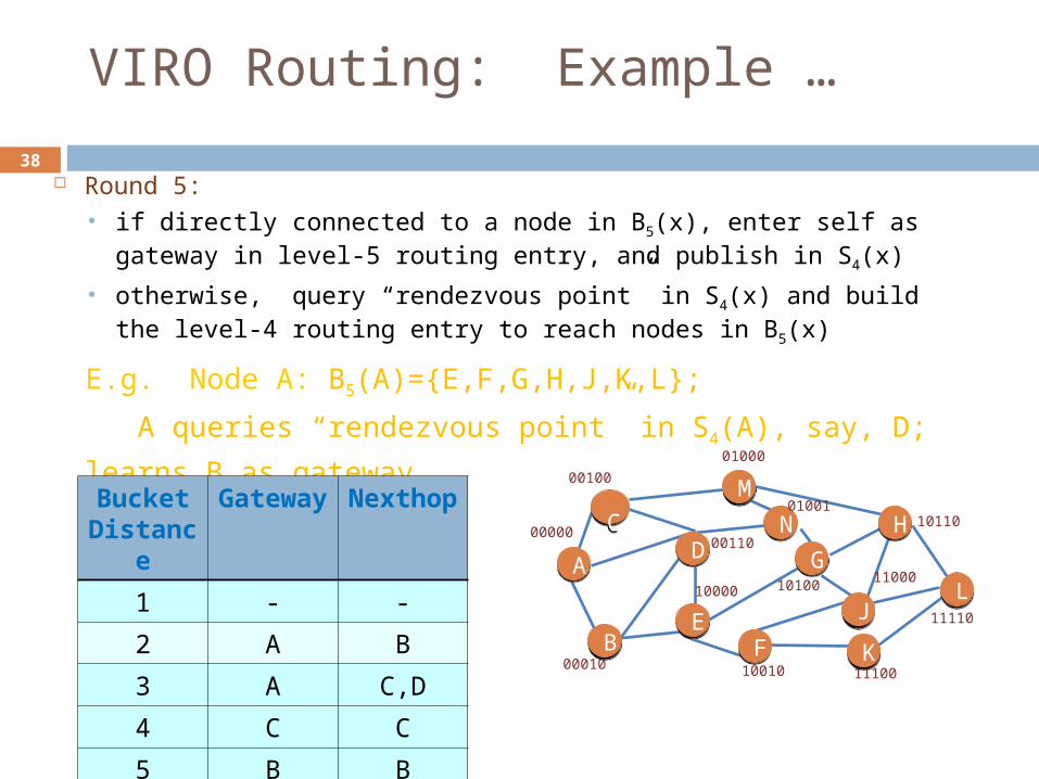
Round 5: if directly connected to a node in B5(x), enter self as gateway in
level-5 routing entry, and publish in S4(x)
otherwise, query “rendezvous point” in S4(x) and build the level-4 routing entry to reach nodes in B5(x)
E.g. Node A: B5(A)={E,F,G,H,J,K,L};
A queries “rendezvous point” in S4(A), say, D; learns B
as gateway
00010 10010 11100
MM
NN HH
GG
JJLL
KK
CC
FFEE
BB
DDAA
00000
00100
00110
01000
01001
10000 10100
10110
11110
11000
Bucket Distan
ce
Gateway
Nexthop
1 - -
2 A B
3 A C,D
4 C C
5 B B

39
Evaluation: vid Assignment
Smaller logical distance shorter physical distances

40
Evaluation: Localized effect of failure
Nodes farther from failed node/link are lesser affected by the failures!
41
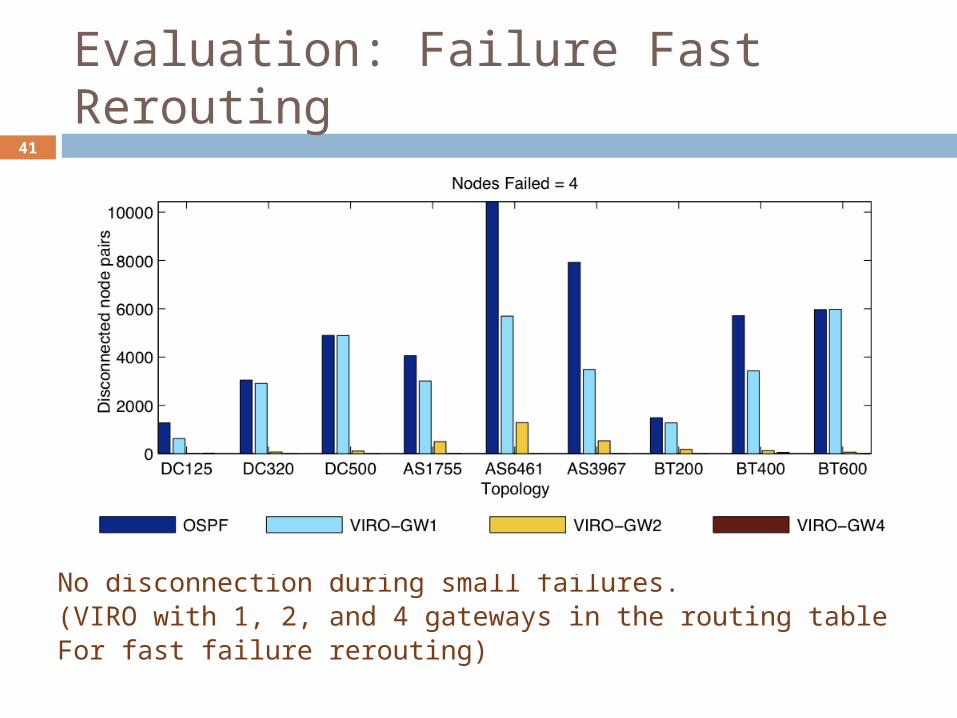
Evaluation: Failure Fast Rerouting
No disconnection during small failures.(VIRO with 1, 2, and 4 gateways in the routing table For fast failure rerouting)
42
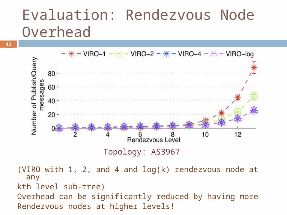
Evaluation: Rendezvous Node Overhead
(VIRO with 1, 2, and 4 and log(k) rendezvous node at anykth level sub-tree)Overhead can be significantly reduced by having moreRendezvous nodes at higher levels!
Topology: AS3967
43
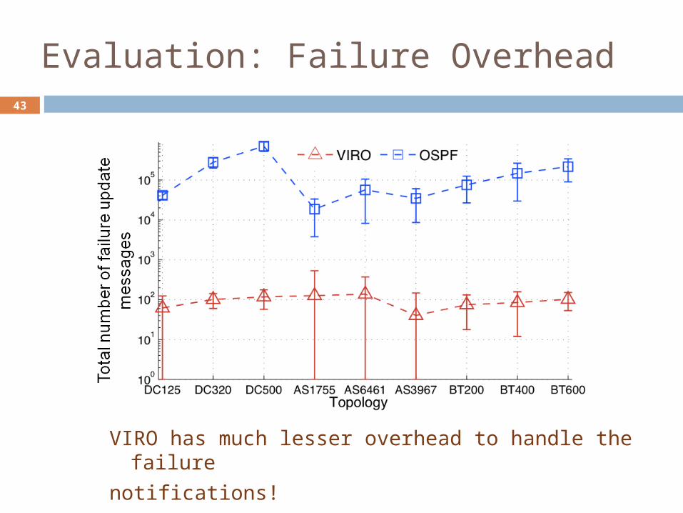
Evaluation: Failure Overhead
VIRO has much lesser overhead to handle the failure
notifications!
44
Other Advantages/Features
Can support multiple namespaces, and inter-operability among such namespaces (e.g., IPv4<->IPv6, IP<->Phone No., etc.) VIRO: “native” naming/address-independent simply incorporate more <namespace, vid> directory services
Fast rerouting can be naturally incorporated no additional complex mechanisms needed
Support multiple topologies or virtualized network services e.g., support for VLANs multiple vid spaces may be constructed
e.g., by defining different types of “physical” neighbors Also facilitate security support
host and access switches can perform access control “persistent” id is not used for data forwarding
eliminate flooding attacks

45
00010 10010 11100
MM
NN HH
GG
JJLL
KK
CC
FFEE
BB
DDAA
00000
00100
00110
01000
01001
10000 10100
10110
11110
11000
Robustness: Localized Failures
Routing table for node A does not change despite the failure!
Link H-L fails
Link H-L fails
Initial TopologyAfter link H-L fails
00010 10010 11100
MM
NN HH
GG
JJLL
KK
CC
FFEE
BB
DDAA
00000
00100
00110
01000
01001
10000 10100
10110
11110
11000
Bucket Distance
Gateway Nexthop
1 - -
2 A B
3 A C,D
4 C C
5 B B