XUWAA•••
EIO0000001328 09/2013
EIO
0000
0013
28.0
1
www.tesensors.com
XUWAA•••Vision Sensors - AdvancedUser Manual
10/2013

The information provided in this documentation contains general descriptions and/or technical characteristics of the performance of the products contained herein. This documentation is not intended as a substitute for and is not to be used for determining suitability or reliability of these products for specific user applications. It is the duty of any such user or integrator to perform the appropriate and complete risk analysis, evaluation and testing of the products with respect to the relevant specific application or use thereof. Neither Schneider Electric nor any of its affiliates or subsidiaries shall be responsible or liable for misuse of the information that is contained herein. If you have any suggestions for improvements or amendments or have found errors in this publication, please notify us.
No part of this document may be reproduced in any form or by any means, electronic or mechanical, including photocopying, without express written permission of Schneider Electric.
All pertinent state, regional, and local safety regulations must be observed when installing and using this product. For reasons of safety and to help ensure compliance with documented system data, only the manufacturer should perform repairs to components.
When devices are used for applications with technical safety requirements, the relevant instructions must be followed.
Failure to use Schneider Electric software or approved software with our hardware products may result in injury, harm, or improper operating results.
Failure to observe this information can result in injury or equipment damage.
© 2013 Schneider Electric. All rights reserved.
2 EIO0000001328 10/2013
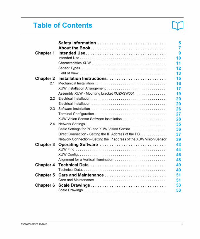
Table of Contents
Safety Information . . . . . . . . . . . . . . . . . . . . . . . . . . . . . 5About the Book. . . . . . . . . . . . . . . . . . . . . . . . . . . . . . . . 7
Chapter 1 Intended Use. . . . . . . . . . . . . . . . . . . . . . . . . . . . . . . . . . 9Intended Use . . . . . . . . . . . . . . . . . . . . . . . . . . . . . . . . . . . . . . . . . . . . 10Characteristics XUW . . . . . . . . . . . . . . . . . . . . . . . . . . . . . . . . . . . . . . 11Sensor Types . . . . . . . . . . . . . . . . . . . . . . . . . . . . . . . . . . . . . . . . . . . 12Field of View . . . . . . . . . . . . . . . . . . . . . . . . . . . . . . . . . . . . . . . . . . . . 13
Chapter 2 Installation Instructions . . . . . . . . . . . . . . . . . . . . . . . . . 152.1 Mechanical Installation . . . . . . . . . . . . . . . . . . . . . . . . . . . . . . . . . . . . 16
XUW Installation Arrangement . . . . . . . . . . . . . . . . . . . . . . . . . . . . . . 17Assembly XUW - Mounting bracket XUZASW001 . . . . . . . . . . . . . . . 19
2.2 Electrical Installation . . . . . . . . . . . . . . . . . . . . . . . . . . . . . . . . . . . . . . 20Electrical Installation . . . . . . . . . . . . . . . . . . . . . . . . . . . . . . . . . . . . . . 20
2.3 Software Installation . . . . . . . . . . . . . . . . . . . . . . . . . . . . . . . . . . . . . . 26Terminal Configuration . . . . . . . . . . . . . . . . . . . . . . . . . . . . . . . . . . . . 27XUW Vision Sensor Software Installation . . . . . . . . . . . . . . . . . . . . . . 28
2.4 Network Settings . . . . . . . . . . . . . . . . . . . . . . . . . . . . . . . . . . . . . . . . . 35Basic Settings for PC and XUW Vision Sensor . . . . . . . . . . . . . . . . . . 36Direct Connection - Setting the IP Address of the PC . . . . . . . . . . . . . 37Network Connection - Setting the IP address of the XUW Vision Sensor 39
Chapter 3 Operating Software . . . . . . . . . . . . . . . . . . . . . . . . . . . . 43XUW Find . . . . . . . . . . . . . . . . . . . . . . . . . . . . . . . . . . . . . . . . . . . . . . 44XUW Config. . . . . . . . . . . . . . . . . . . . . . . . . . . . . . . . . . . . . . . . . . . . . 46Alignment for a Vertical Illumination . . . . . . . . . . . . . . . . . . . . . . . . . . 48
Chapter 4 Technical Data . . . . . . . . . . . . . . . . . . . . . . . . . . . . . . . . 49Technical Data. . . . . . . . . . . . . . . . . . . . . . . . . . . . . . . . . . . . . . . . . . . 49
Chapter 5 Care and Maintenance . . . . . . . . . . . . . . . . . . . . . . . . . . 51Care and Maintenance . . . . . . . . . . . . . . . . . . . . . . . . . . . . . . . . . . . . 51
Chapter 6 Scale Drawings . . . . . . . . . . . . . . . . . . . . . . . . . . . . . . . . 53Scale Drawings . . . . . . . . . . . . . . . . . . . . . . . . . . . . . . . . . . . . . . . . . . 53
EIO0000001328 10/2013 3

4 EIO0000001328 10/2013

Safety Information
Important Information
NOTICERead these instructions carefully, and look at the equipment to become familiar with the device before trying to install, operate, or maintain it. The following special messages may appear throughout this documentation or on the equipment to warn of potential hazards or to call attention to information that clarifies or simplifies a procedure.
EIO0000001328 10/2013 5

PLEASE NOTEElectrical equipment should be installed, operated, serviced, and maintained only by qualified personnel. No responsibility is assumed by Schneider Electric for any consequences arising out of the use of this material.
A qualified person is one who has skills and knowledge related to the construction and operation of electrical equipment and its installation, and has received safety training to recognize and avoid the hazards involved.
6 EIO0000001328 10/2013
About the Book
At a Glance
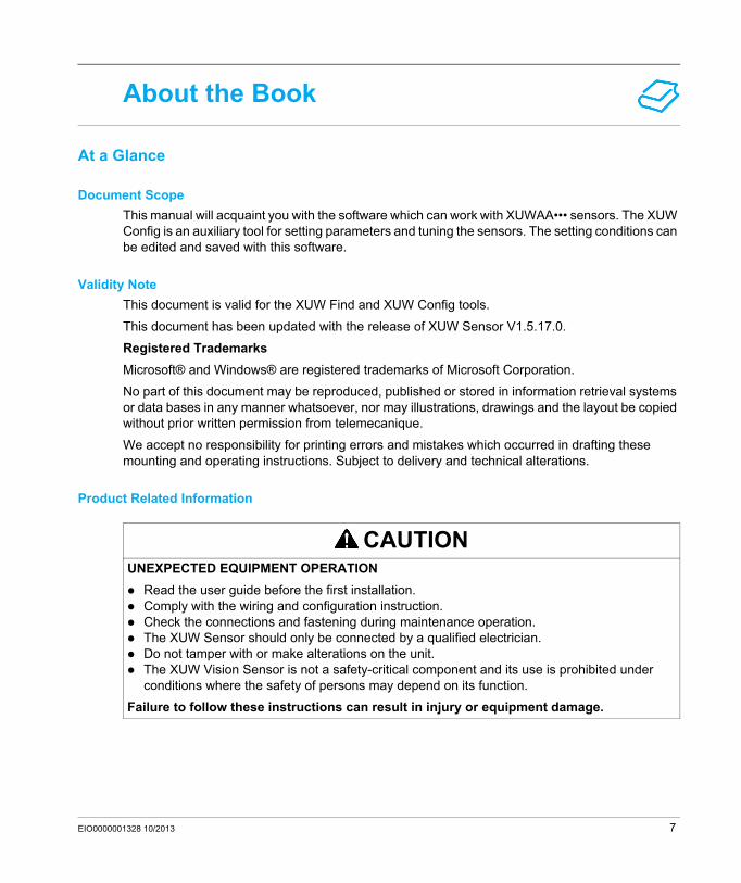
Document ScopeThis manual will acquaint you with the software which can work with XUWAA••• sensors. The XUW Config is an auxiliary tool for setting parameters and tuning the sensors. The setting conditions can be edited and saved with this software.
Validity NoteThis document is valid for the XUW Find and XUW Config tools.
This document has been updated with the release of XUW Sensor V1.5.17.0.
Registered TrademarksMicrosoft® and Windows® are registered trademarks of Microsoft Corporation.
No part of this document may be reproduced, published or stored in information retrieval systems or data bases in any manner whatsoever, nor may illustrations, drawings and the layout be copied without prior written permission from telemecanique.
We accept no responsibility for printing errors and mistakes which occurred in drafting these mounting and operating instructions. Subject to delivery and technical alterations.
Product Related Information
CAUTIONUNEXPECTED EQUIPMENT OPERATION
Read the user guide before the first installation.Comply with the wiring and configuration instruction.Check the connections and fastening during maintenance operation.The XUW Sensor should only be connected by a qualified electrician.Do not tamper with or make alterations on the unit.The XUW Vision Sensor is not a safety-critical component and its use is prohibited under conditions where the safety of persons may depend on its function.
Failure to follow these instructions can result in injury or equipment damage.
EIO0000001328 10/2013 7
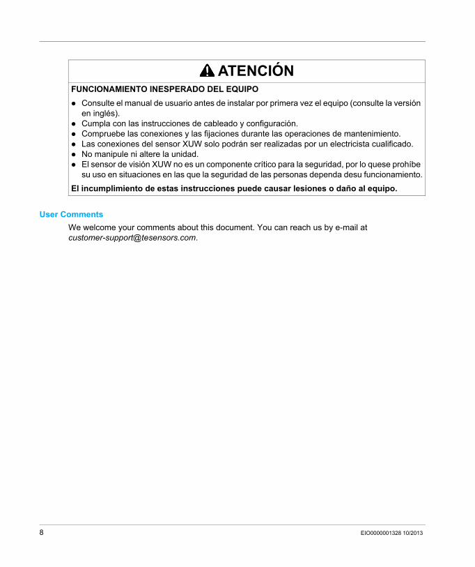
User CommentsWe welcome your comments about this document. You can reach us by e-mail at [email protected].
ATENCIÓNFUNCIONAMIENTO INESPERADO DEL EQUIPO
Consulte el manual de usuario antes de instalar por primera vez el equipo (consulte la versión en inglés).Cumpla con las instrucciones de cableado y configuración.Compruebe las conexiones y las fijaciones durante las operaciones de mantenimiento.Las conexiones del sensor XUW solo podrán ser realizadas por un electricista cualificado.No manipule ni altere la unidad.El sensor de visión XUW no es un componente crítico para la seguridad, por lo quese prohíbe su uso en situaciones en las que la seguridad de las personas dependa desu funcionamiento.
El incumplimiento de estas instrucciones puede causar lesiones o daño al equipo.
8 EIO0000001328 10/2013

XUWAA•••Intended UseEIO0000001328 09/2013
Intended Use
Chapter 1Intended Use
What Is in This Chapter?This chapter contains the following topics:
Topic Page
Intended Use 10
Characteristics XUW 11
Sensor Types 12
Field of View 13
EIO0000001328 10/2013 9

Intended Use
Intended Use
Field of applicationThe XUW Vision Sensor precisely detects defective parts, parts in the wrong place, at the wrong angle or in the wrong order or a combination of all of these. A total of five detectors are available for inspection tasks and interpretation:
pattern matchingcontour detectionbrightnessgrey levelcontrast detection
The advanced version of the XUW Vision Sensor, XUW-Advanced also offers position tracking: it is thus now also possible to reliably detect those features which do not appear with repeated accuracy in the taught position. All interpretation is carried out relative to the actual position and angle of the part without having to define an independent characteristic for each possible position. This high capacity tool also enables you to solve demanding pick and place applications.
10 EIO0000001328 10/2013
Intended Use
Characteristics XUW
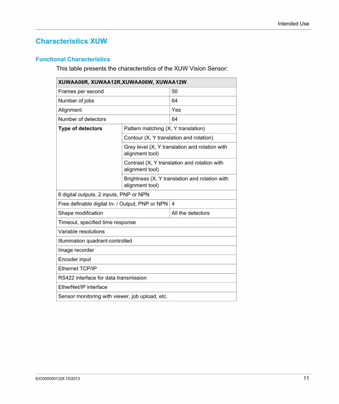
Functional CharacteristicsThis table presents the characteristics of the XUW Vision Sensor:
XUWAA06R, XUWAA12R,XUWAA06W, XUWAA12W
Frames per second 50
Number of jobs 64
Alignment Yes
Number of detectors 64
Type of detectors Pattern matching (X, Y translation)
Contour (X, Y translation and rotation)
Grey level (X, Y translation and rotation with alignment tool)
Contrast (X, Y translation and rotation with alignment tool)
Brightness (X, Y translation and rotation with alignment tool)
6 digital outputs, 2 inputs, PNP or NPN
Free definable digital In- / Output, PNP or NPN 4
Shape modification All the detectors
Timeout, specified time response
Variable resolutions
Illumination quadrant-controlled
Image recorder
Encoder input
Ethernet TCP/IP
RS422 interface for data transmission
EtherNet/IP interface
Sensor monitoring with viewer, job upload, etc.
EIO0000001328 10/2013 11
Intended Use
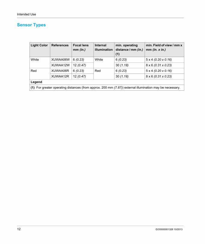
Sensor Types
Light Color References Focal lens mm (in.)
Internal illumination
min. operating distance / mm (in.) (1)
min. Field of view / mm x mm (in. x in.)
White XUWAA06W 6 (0.23) White 6 (0.23) 5 x 4 (0.20 x 0.16)
XUWAA12W 12 (0.47) 30 (1.18) 8 x 6 (0.31 x 0.23)
Red XUWAA06R 6 (0.23) Red 6 (0.23) 5 x 4 (0.20 x 0.16)
XUWAA12R 12 (0.47) 30 (1.18) 8 x 6 (0.31 x 0.23)
Legend
(1) For greater operating distances (from approx. 200 mm (7.87)) external illumination may be necessary.
12 EIO0000001328 10/2013
Intended Use
Field of View
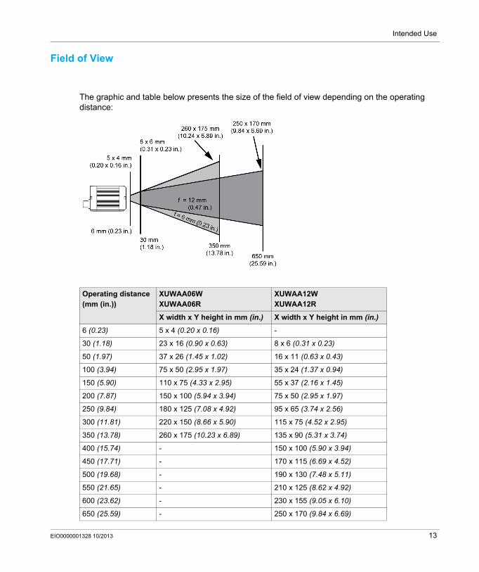
The graphic and table below presents the size of the field of view depending on the operating distance:
Operating distance (mm (in.))
XUWAA06WXUWAA06R
XUWAA12WXUWAA12R
X width x Y height in mm (in.) X width x Y height in mm (in.)
6 (0.23) 5 x 4 (0.20 x 0.16) -
30 (1.18) 23 x 16 (0.90 x 0.63) 8 x 6 (0.31 x 0.23)
50 (1.97) 37 x 26 (1.45 x 1.02) 16 x 11 (0.63 x 0.43)
100 (3.94) 75 x 50 (2.95 x 1.97) 35 x 24 (1.37 x 0.94)
150 (5.90) 110 x 75 (4.33 x 2.95) 55 x 37 (2.16 x 1.45)
200 (7.87) 150 x 100 (5.94 x 3.94) 75 x 50 (2.95 x 1.97)
250 (9.84) 180 x 125 (7.08 x 4.92) 95 x 65 (3.74 x 2.56)
300 (11.81) 220 x 150 (8.66 x 5.90) 115 x 75 (4.52 x 2.95)
350 (13.78) 260 x 175 (10.23 x 6.89) 135 x 90 (5.31 x 3.74)
400 (15.74) - 150 x 100 (5.90 x 3.94)
450 (17.71) - 170 x 115 (6.69 x 4.52)
500 (19.68) - 190 x 130 (7.48 x 5.11)
550 (21.65) - 210 x 125 (8.62 x 4.92)
600 (23.62) - 230 x 155 (9.05 x 6.10)
650 (25.59) - 250 x 170 (9.84 x 6.69)
EIO0000001328 10/2013 13
Intended Use
14 EIO0000001328 10/2013

XUWAA•••Installation InstructionsEIO0000001328 09/2013
Installation Instructions
Chapter 2Installation Instructions
What Is in This Chapter?This chapter contains the following sections:
Section Topic Page
2.1 Mechanical Installation 16
2.2 Electrical Installation 20
2.3 Software Installation 26
2.4 Network Settings 35
EIO0000001328 10/2013 15

Installation Instructions
Mechanical Installation
Section 2.1Mechanical Installation
What Is in This Section?This section contains the following topics:
Topic Page
XUW Installation Arrangement 17
Assembly XUW - Mounting bracket XUZASW001 19
16 EIO0000001328 10/2013

Installation Instructions
XUW Installation Arrangement
Installation Precautions
NOTE: The IP address set for the XUW Vision Sensor should be marked on the enclosed label. After installation, stick the label on the sensor in a clearly visible position.
InstallationScrew the XUW Vision Sensor onto the mounting clamp XUZASW001 (supplied with the unit) and then onto a suitable object. You can use also the mounting clamp XUZASW002 or the mounting clamp XUZASW008 (for rod profile diam. 12).
The XUW Vision Sensor has two methods of illumination:Dark-field: which prevents direct reflections and accentuation of edges etc. Bright-field: which transmits light/measures tasks of the accentuation of highly-reflective objects.
NOTICEUNEXPECTED EQUIPMENT OPERATION
To ensure maximum accuracy of detection, the XUW Vision Sensor should be protected from vibrations.Secure the supply and I/O cables with cable binders to prevent crushing or slipping.Select a position for the XUW Vision Sensor in which interfering factors such as slight differences in the position of the object or variations in illumination have little or no effect.Fine adjustment should not be carried out after electrical connection and start-up (PC software installation).
Failure to follow these instructions can result in equipment damage.
EIO0000001328 10/2013 17
Installation Instructions
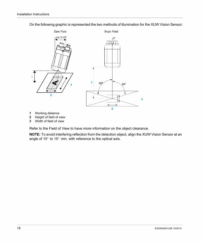
On the following graphic is represented the two methods of illumination for the XUW Vision Sensor:
1 Working distance2 Height of field of view3 Width of field of view
Refer to the Field of View to have more information on the object clearance.
NOTE: To avoid interfering reflection from the detection object, align the XUW Vision Sensor at an angle of 10° to 15° min. with reference to the optical axis.
18 EIO0000001328 10/2013
Installation Instructions
Assembly XUW - Mounting bracket XUZASW001
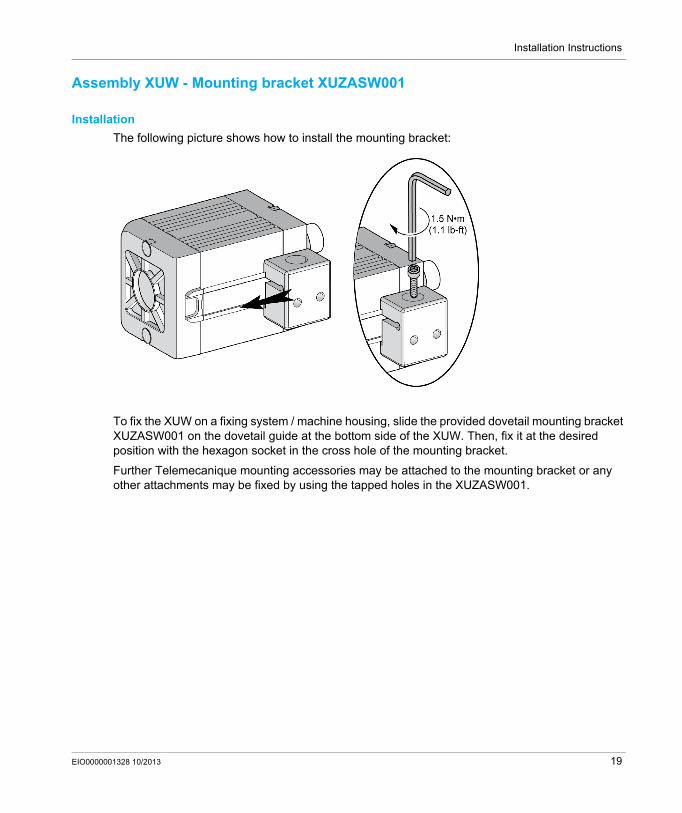
InstallationThe following picture shows how to install the mounting bracket:
To fix the XUW on a fixing system / machine housing, slide the provided dovetail mounting bracket XUZASW001 on the dovetail guide at the bottom side of the XUW. Then, fix it at the desired position with the hexagon socket in the cross hole of the mounting bracket.
Further Telemecanique mounting accessories may be attached to the mounting bracket or any other attachments may be fixed by using the tapped holes in the XUZASW001.
EIO0000001328 10/2013 19

Installation Instructions
Electrical Installation
Section 2.2Electrical Installation
Electrical Installation
Installation Precaution
XUW Sensor Rear Module ConnectionThe following graphic shows the electrical connection on the rear of the XUW Sensor:
1 Operating LED2 Output LEDs (see the following details)3 Focus Adjustable4 Power supply and digital I/O M12 connector5 Ethernet M12 connector6 Data (RS422) M12 connector
NOTICEUNEXPECTED EQUIPMENT OPERATION
The XUW Sensor should only be connected by a qualified electrician.Remove all electrical components from the power supply before installing the XUW Vision Sensor.Do not connect this module to your network until you have ensured that its IP address will be unique on the network.The protective caps supplied must be pushed onto the M12 sockets (LAN) which are not in use.
Failure to follow these instructions can result in equipment damage.
20 EIO0000001328 10/2013

Installation Instructions
The following table shows the LED status:
LAN Connection
The XUW Sensor can be connected to a PC directly or via a network.
The following graphic shows the two LAN connection. The upper part represents the Direct connection of the XUW Vision sensor to a PC and the lower part the connection of the XUW Vision sensor to a PC via a network:
1 Ethernet cable M12, 5 pins / XZCPB12P15L••2 Ethernet cable M12 / XGSZ•2E45••3 Power cable M12, 12 pins / XZCPB4•P14L••4 Ethernet cable M12 / XGSZ•2E45••5 Ethernet cable RJ456 Network switch
Name Color Meaning Pin / Wire Colors
Pwr. Green Operating voltage -
A Yellow Result 1 12 / Red/Blue
B Yellow Result 2 07 / Black
C Yellow Result 3 08 / Gray
NOTICEUNEXPECTED EQUIPMENT BEHAVIORUse only the correct network cable.
Failure to follow these instructions can result in equipment damage.
EIO0000001328 10/2013 21

Installation Instructions
Plug ConnectionsThe following graphic and table present the PIN assignment for the power cable:
PIN Color Use
1 Brown +Ub (24 Vdc)
2 Blue GND
3 White IN
41 Green READY4 output
5 Pink Input / Output (Encoder -)
6 Yellow Input / Output4
72 Black Input / Output4
82 Gray Input / Output4
9 Red Output
10 Purple Input (Encoder +)
11 Gray/Pink Valid4 output3
12 Red/Blue Output4 (100 mA ejector)
1 Ready: Sensor ready for a new trigger2 Configurable digital inputs-outputs3 VALID: indicated that results are available4 PNP or NPN inputs/outputs
22 EIO0000001328 10/2013

Installation Instructions
The following graphic and table present the PIN assignment for the ethernet cable:
The following graphic and table present the PIN assignment for the data cable (RS422):
PIN Color PIN (RJ45) Use
1 Yellow 1 RxD+
2 White 3 TxD+
3 Orange 2 RxD-
4 Blue 6 TxD-
PIN Color Use
1 White RxD+
2 Brown RxD-
3 Black TxD+
4 Blue TxD-
5 Grey GND
EIO0000001328 10/2013 23
Installation Instructions
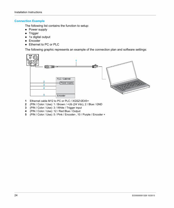
Connection ExampleThe following list contains the function to setup:
Power supplyTrigger1x digital outputEncoderEthernet to PC or PLC
The following graphic represents an example of the connection plan and software settings:
1 Ethernet cable M12 to PC or PLC / XGSZ•2E45••2 (PIN / Color / Use): 1 / Brown / +Ub (24 Vdc), 2 / Blue / GND3 (PIN / Color / Use): 3 / White / Trigger input4 (PIN / Color / Use): 12 / Red Blue / Output5 (PIN / Color / Use): 5 / Pink / Encoder-, 10 / Purple / Encoder +
24 EIO0000001328 10/2013

Installation Instructions
Wiring Diagram: PNP or NPN applicationThe following graphic shows the wiring diagram for PNP or NPN application:
NOTE: In PNP mode:
In-/outputs switch to +24 Vdc.
NOTE: In NPN mode:
As the inputs refer to ground, an additional pull-up resistor may be required in order to increase the input voltage to 24 Vdc when unswitched. The outputs switch to ground.
EIO0000001328 10/2013 25
Installation Instructions
Software Installation
Section 2.3Software Installation
What Is in This Section?This section contains the following topics:
Topic Page
Terminal Configuration 27
XUW Vision Sensor Software Installation 28
26 EIO0000001328 10/2013

Installation Instructions
Terminal Configuration
Required Operating SystemXUW Vision Sensor requires one of the following operating systems to be present on the terminal:
Windows 2000 Edition® SP4Windows XP Professional Edition® SP2Windows Vista Business Edition® 32 bitsWindows 7 Professional Edition® 32 and 64 bits system
Other RequirementsThe following are required before installing XUW software:
Internet Explorer V6.0 or later.NET 4.0 Framework, SP2Windows Installer V3.1 or laterVisual C++ 2008 Runtime
Terminal ConfigurationThe following table provides the minimum and recommended terminal characteristics necessary to install:
NOTE: The XUW Vision Sensor is supplied with the IP address 192.168.100.100 and a subnet mask 255.255.255.0.
Minimum and recommended terminal configuration with Microsoft Windows 2000 Edition SP4 / Windows XP Professional Edition with SP2 / Windows Vista Business Edition 32 / Windows 7 Professional Edition_32 and 64
System Pentium processor 1 GHz or higher; recommended 2 Ghz
RAM recommended 1 GBytes
Operating System Microsoft Windows 2000 Edition SP4 / Windows XP Professional Edition with SP2 / Windows Vista Business Edition 32 / Windows 7 Professional Edition_32 and 64
Display SVGA 1024x768 or higher resolution monitor with high color 24 bits
Other network connection or network with TCP-IP protocol
EIO0000001328 10/2013 27
Installation Instructions
XUW Vision Sensor Software Installation
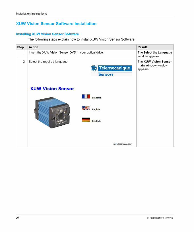
Installing XUW Vision Sensor SoftwareThe following steps explain how to install XUW Vision Sensor Software:
Step Action Result
1 Insert the XUW Vision Sensor DVD in your optical drive The Select the Language window appears.
2 Select the required language. The XUW Vision Sensor main window window appears.
28 EIO0000001328 10/2013
Installation Instructions
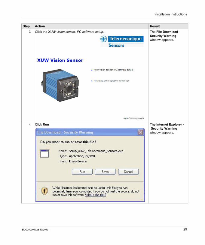
3 Click the XUW vision sensor. PC software setup. The File Download - Security Warning window appears.
4 Click Run The Internet Explorer -Security Warning
window appears.
Step Action Result
EIO0000001328 10/2013 29
Installation Instructions
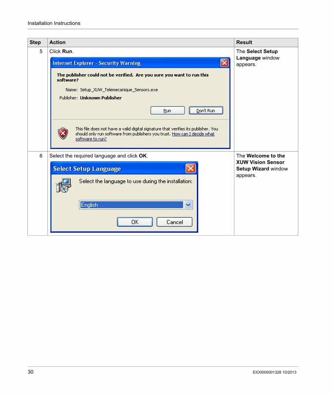
5 Click Run. The Select Setup Language window appears.
6 Select the required language and click OK. The Welcome to the XUW Vision Sensor Setup Wizard window appears.
Step Action Result
30 EIO0000001328 10/2013
Installation Instructions
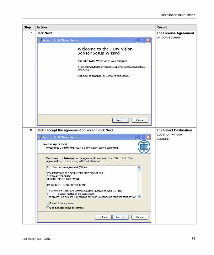
7 Click Next. The License Agreement window appears.
8 Click I accept the agreement option and click Next. The Select Destination Location window appears.
Step Action Result
EIO0000001328 10/2013 31
Installation Instructions
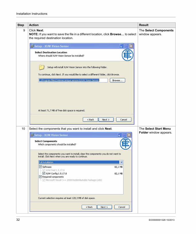
9 Click Next.NOTE: If you want to save the file in a different location, click Browse… to select the required destination location.
The Select Components window appears.
10 Select the components that you want to install and click Next. The Select Start Menu Folder window appears.
Step Action Result
32 EIO0000001328 10/2013

Installation Instructions
11 Click Next.NOTE: If you want to select a different folder, click Browse… to select the required folder.
The Select Additional Tasks window appears.
12 Select the required additional tasks and click Next. The Ready to Install window appears.
Step Action Result
EIO0000001328 10/2013 33
Installation Instructions
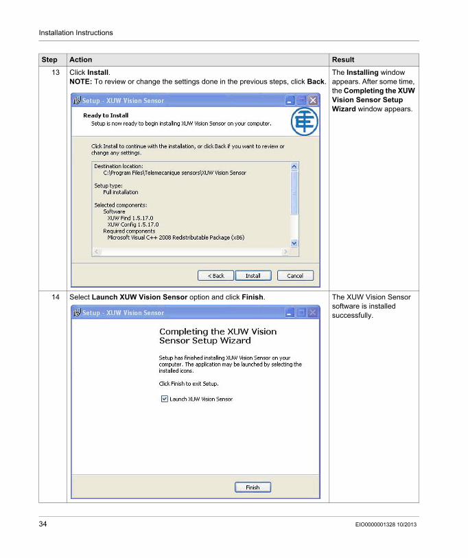
13 Click Install.NOTE: To review or change the settings done in the previous steps, click Back.
The Installing window appears. After some time, the Completing the XUW Vision Sensor Setup Wizard window appears.
14 Select Launch XUW Vision Sensor option and click Finish. The XUW Vision Sensor software is installed successfully.
Step Action Result
34 EIO0000001328 10/2013
Installation Instructions
Network Settings
Section 2.4Network Settings
What Is in This Section?This section contains the following topics:
Topic Page
Basic Settings for PC and XUW Vision Sensor 36
Direct Connection - Setting the IP Address of the PC 37
Network Connection - Setting the IP address of the XUW Vision Sensor 39
EIO0000001328 10/2013 35

Installation Instructions
Basic Settings for PC and XUW Vision Sensor
The following instructions indicate how to change the network configuration of the PC and the XUW Vision Sensor.
To configure the XUW Vision Sensor with a PC it is essential that a network board and the TCP/IP LAN- connection is installed on the PC (This also applies when the PC is not connected to a network). The XUW supports the automatic recognition of the Ethernet transmission rate, but 100 MBit at the most. The internet protocol IPv4 must be activated.
The XUW Vision Sensor has to alternatives to be configured and parameterized:Direct ConnectionNetwork Connection
NOTICEUNEXPECTED EQUIPMENT OPERATION
Correct settings have to be used otherwise the network connections may be lost.Contact the system administrator in order to determine which IP addresses are allowed in yout network or locally in your PC.Record the former settings for later use.
Failure to follow these instructions can result in equipment damage.
36 EIO0000001328 10/2013
Installation Instructions
Direct Connection - Setting the IP Address of the PC
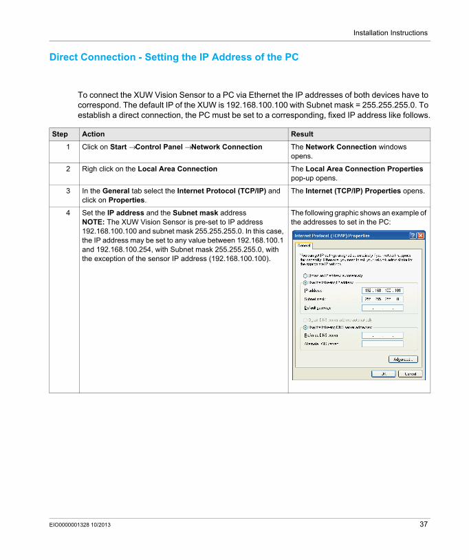
To connect the XUW Vision Sensor to a PC via Ethernet the IP addresses of both devices have to correspond. The default IP of the XUW is 192.168.100.100 with Subnet mask = 255.255.255.0. To establish a direct connection, the PC must be set to a corresponding, fixed IP address like follows.
Step Action Result
1 Click on Start → Control Panel → Network Connection The Network Connection windows opens.
2 Righ click on the Local Area Connection The Local Area Connection Properties pop-up opens.
3 In the General tab select the Internet Protocol (TCP/IP) and click on Properties.
The Internet (TCP/IP) Properties opens.
4 Set the IP address and the Subnet mask addressNOTE: The XUW Vision Sensor is pre-set to IP address 192.168.100.100 and subnet mask 255.255.255.0. In this case, the IP address may be set to any value between 192.168.100.1 and 192.168.100.254, with Subnet mask 255.255.255.0, with the exception of the sensor IP address (192.168.100.100).
The following graphic shows an example of the addresses to set in the PC:
EIO0000001328 10/2013 37

Installation Instructions
Proceeding/ Troubleshooting - Direct ConnectionThe following troubleshooting flowchart will help you find solutions to difficulties you might encounter during the installation of the sensor:
38 EIO0000001328 10/2013
Installation Instructions
Network Connection - Setting the IP address of the XUW Vision Sensor
If the sensor IP is still free, the sensor can be connected to the network and the IP address can be set to match IP address of the PC.
Sensor IP is free:Connect sensor to network and then set the sensor’s IP to match the PC according to the administrator’s specifications, as follows, beginning with 2.
Sensor IP is already assigned:1. Connect sensor and PC directly and set an authorized IP address in the sensor2. Connection via the network can than be carried out
NOTE: Ensure electrical connection and installation of PC software have been completed.
NOTICEUNEXPECTED EQUIPMENT OPERATION
Check with the network administrator whether the sensor address has already been assigned (IP address: 192.168.100.100 with Subnet mask 255.255.255.0).Contact the system administrator in order to determine which IP addresses are allowed in your network or locally in your PC.A 100MBit/full-duplex connection must be used when using VGA resolution and XUW View.
Failure to follow these instructions can result in equipment damage.
EIO0000001328 10/2013 39
Installation Instructions
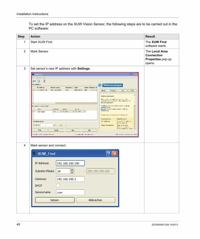
To set the IP address on the XUW Vision Sensor, the following steps are to be carried out in the PC software:
Step Action Result
1 Start XUW Find The XUW Find software starts.
2 Mark Sensor The Local Area Connection Properties pop-up opens.
3 Set sensor’s new IP address with Settings.
4 Mark sensor and connect.
40 EIO0000001328 10/2013

Installation Instructions
Proceeding/Troubleshooting - Network ConnectionThe following troubleshooting flowchart will help you find solutions to difficulties you might encounter during the installation of the sensor:
EIO0000001328 10/2013 41
Installation Instructions
42 EIO0000001328 10/2013
XUWAA•••Operating softwareEIO0000001328 09/2013
Operating Software
Chapter 3Operating Software
What Is in This Chapter?This chapter contains the following topics:
Topic Page
XUW Find 44
XUW Config 46
Alignment for a Vertical Illumination 48
EIO0000001328 10/2013 43
Operating software
XUW Find
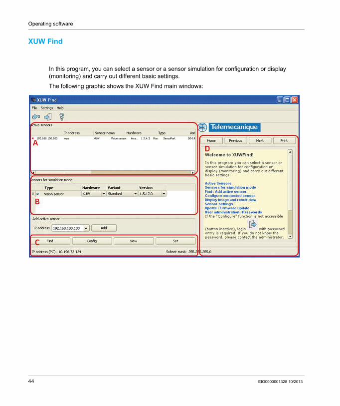
In this program, you can select a sensor or a sensor simulation for configuration or display (monitoring) and carry out different basic settings.
The following graphic shows the XUW Find main windows:
44 EIO0000001328 10/2013

Operating software
This table explains the operating fields:
NOTE: Further information can be found in the context - sensitive online help of the software.
Operating Field
Name Description
A Active sensors This list displays all the XUW Vision Sensors which can be controlled from the PC.
B Sensors for simulation mode All the sensors available for offline simulation are displayed here.
C Function Find Activates another search procedure
Configure Configures a connected sensor or sensor simulation
Display Displays image or result data from a connected sensor
Set The sensor’s network setting
D Context help Context-sensitive help on the current topic
EIO0000001328 10/2013 45

Operating software
XUW Config
With this program, you can configure your XUW vision sensor for one or several jobs in six logical operating steps. Activate the Configure button in the XUW Find module to start Senso Config.
The following graphic show the XUW Config main window:
46 EIO0000001328 10/2013

Operating software
This table explains the operating fields:
NOTE: Further information can be found in the context - sensitive online help of the software.
Operating Field
Name Description
A Menu and tool bar
B Setup navigation / Operating steps
C Image Image output with graphically adjustable operating and search zones as well as zoom function and filmstrip navigation
D Online help Context-sensitive online help, automatically updated for each action.
E Image acquisition Switch-over between continuous and single image mode and software trigger.
F Mode of connection Switch-over between online and offline mode (sensor present or simulation without sensor).
G Configuration window Variable content relating to action in set-up navigation, for setting associated parameters.
H Status bar Displays various information about the sensor (mode, name, memory status, and so on).
EIO0000001328 10/2013 47
Operating software
Alignment for a Vertical Illumination
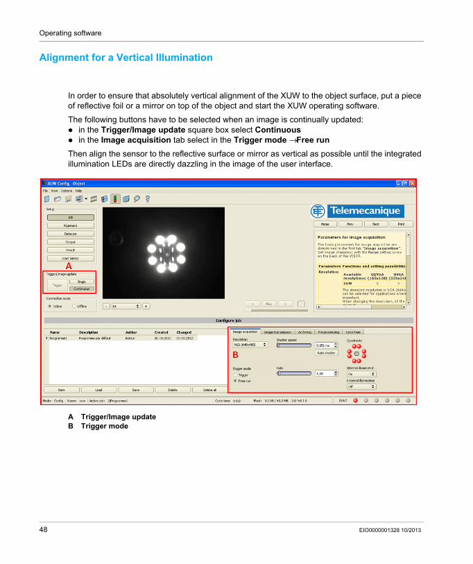
In order to ensure that absolutely vertical alignment of the XUW to the object surface, put a piece of reflective foil or a mirror on top of the object and start the XUW operating software.
The following buttons have to be selected when an image is continually updated:in the Trigger/Image update square box select Continuousin the Image acquisition tab select in the Trigger mode → Free run
Then align the sensor to the reflective surface or mirror as vertical as possible until the integrated illumination LEDs are directly dazzling in the image of the user interface.
A Trigger/Image updateB Trigger mode
48 EIO0000001328 10/2013
XUWAA•••Technical DataEIO0000001328 09/2013
Technical Data
Chapter 4Technical Data
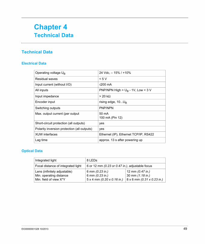
Technical Data
Electrical Data
Optical Data
Operating voltage UB 24 Vdc, – 15% / +10%
Residual waves < 5 V
Input current (without I/O) ≤ 200 mA
All inputs PNP/NPN High > UB - 1V, Low < 3 V
Input impedance > 20 kΩ
Encoder input rising edge, 10...UB
Switching outputs PNP/NPN
Max. output current (per output 50 mA100 mA (Pin 12)
Short-circuit protection (all outputs) yes
Polarity inversion protection (all outputs) yes
XUW interfaces Ethernet (IP), Ethernet TCP/IP, RS422
Lag time approx. 13 s after powering up
Integrated light 8 LEDs
Focal distance of integrated light 6 or 12 mm (0.23 or 0.47 in.), adjustable focus
Lens (infinitely adjustable)Min. operating distance Min. field of view X*Y
6 mm (0.23 in.)6 mm (0.23 in.)5 x 4 mm (0.20 x 0.16 in.)
12 mm (0.47 in.)30 mm (1.18 in.)8 x 6 mm (0.31 x 0.23 in.)
EIO0000001328 10/2013 49

Technical Data
Mechanical Data
Function and Characteristics
Length x Width x Height 65 x 45 x 45 mm (2.56 x 1.77 x 1.77 in.) (without connector)
Weight approx. 160 g
Vibration/shocks Complying with EN 60947-5-2
Operating temperature 0... 50 ° C (80% air humidity, no condensation)
Storage temperature - 20... 60 ° C (80% air humidity, no condensation)
IP Code IP 65/67
Connection Power and I/O: M12 12 poleEthernet: M12 4 poleData: M12 5 pole
Casing material ABS/aluminium/ABS
Front face material PMMA
Number of jobs 64
Evaluation modes Alignment functioncontour match with/without position detectionpattern match with/without position detectionarea test grey levelarea test contrastarea test brightnessdirection info, or coordinates for position detection
Minimum cycle time typ. 15 ms pattern matchingtyp. 30 ms contourtyp. 2 ms area tests
50 EIO0000001328 10/2013
XUWAA•••Care and MaintenanceEIO0000001328 09/2013
Chapter 5Care and Maintenance
Care and Maintenance
CleaningThe XUW Vision Sensor must be cleaned with a clean and dry cloth.
Dirt on the front panel must be cleaned with a soft cloth and a small amount of plastic cleaner if necessary.
Waste disposalElectronic components are subject to special waste regulations and may only be disposed of by specialist waste disposal firms.
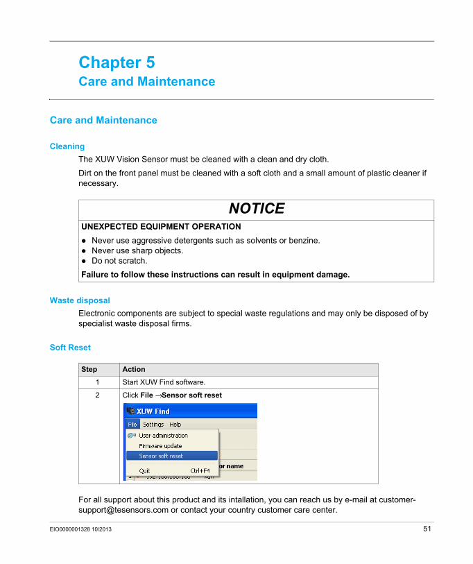
Soft Reset
For all support about this product and its intallation, you can reach us by e-mail at [email protected] or contact your country customer care center.
NOTICEUNEXPECTED EQUIPMENT OPERATION
Never use aggressive detergents such as solvents or benzine.Never use sharp objects.Do not scratch.
Failure to follow these instructions can result in equipment damage.
Step Action
1 Start XUW Find software.
2 Click File → Sensor soft reset
EIO0000001328 10/2013 51

Care and Maintenance
52 EIO0000001328 10/2013

XUWAA•••Scale DrawingsEIO0000001328 09/2013
Scale Drawings
Chapter 6Scale Drawings
Scale Drawings
The following graphic shows the dimension of the XUW Vision sensor:
The following graphic shows the XUZASW001 mounting clamp:
EIO0000001328 10/2013 53

Scale Drawings
54 EIO0000001328 10/2013