William L. Hwang†, Fei Su‡, Krishnendu ChakrabartyDepartment of Electrical & Computer Engineering
Duke University, Durham, NC 27708, USA
Automated Design of Pin-Constrained Digital Microfluidic Arrays for
Lab-on-a-Chip Applications
† Department of Physics, University Of Oxford‡ Intel Corporation
Motivation for Biochips• Transfer conventional biochemical laboratory methods
to lab-on-a-chip (LoC), or microfluidic biochips
• Potential to revolutionize biosensing, clinical diagnostics, drug discovery– Small size and sample volumes, O(nL)– Lower cost– Higher sensitivity
Conventional Biochemical Analyzer
Shrink
Digital Microfluidic Biochip

Microfluidic Biochips• Based on precise control of very small volumes
of liquids
• Integrate various fluid-handling functions such as sample prep, analysis, separation, and detection
• Most commercially available microfluidic devices are continuous-flow– Permanently etched microchannels, pumps, and valves
(University of Michigan) 1998
(Duke University) 2002

Microfluidic Biochips• Digital microfluidic biochips (DMBs)
– Manipulate discrete droplets (smaller volumes)– Electrical actuation– No need for cumbersome micropumps and microvalves– Dynamic reconfigurability (virtual routes)– Architectural scalability and greater automation– System clock controls droplet motion; similar in operation
to digital microprocessor
(University of Michigan) 1998
(Duke University) 2002

Electrowetting• Novel microfluidic platform invented at Duke University
• Droplet actuation achieved through an effect called electrowetting
No PotentialA droplet on a hydrophobic surface originally has a large contact angle.
Applied PotentialThe droplet’s surface energy increases, which results in a reduced contact angle. The droplet now wets the surface.

Actuation Principle
• Droplets containing samples travel inside filler medium (e.g., silicone oil), sandwiched in between glass plates
• Bottom plate – patterned array of control electrodes
• Top plate – continuous ground electrode
• Surfaces are insluated (Parylene) and hydrophobic (Teflon AF)

Actuation Principle
• Droplet transport occurs by removing potentialon current electrode, applying potential on an adjacent electrode
• Interfacial tensiongradient created

PCB Microfluidic Biochips• Rapid prototyping and inexpensive mass-fabrication
• Copper layer for electrodes (coplanar grounding rails)
• Solder mask for insulator
• Teflon AF coating for hydrophobicity
Disposable PCB biochip plugged into controller circuit board, programmed and powered with USB port

OUTLINE• What are digital microfluidic biochips (DMBs)?
• Pin-Constrained Digital Microfluidic Biochips– Background– Pin Assignment Problem
• Minimum Number of Pins for Single Droplet • Pin-Assignment Problem for Two Droplets
– Virtual Partitioning Scheme
• Impact of Partitioning on PCNI• Evaluation Example: Multiplexed Bioassays
• Summary and future outlook

Direct Addressing• Most design and CAD research for DMBs has been
focused on directly-addressable chips
• Suitable for small/medium-scale microfluidic electrode arrays (e.g., with fewer than 10 x 10 electrodes)
• For large-scale DMBs (e.g., > 100 x 100 electrodes), multi-layer electrical connection structures and complicated routing solutions are needed for that many control pins
Pin-Constrained DMBs• Product cost is major marketability driver due to
disposable nature of most emerging devices
• Multiple metal layers for PCB design may lead to reliability problems and increase fabrication cost
• Reduce number of independent control pins(pin-constrained DMBs)– Reduce input bandwidth between electronic controller
and microfluidic array while minimizing any decrease in performance

Pin-Constrained DMBs• Pin-constrained array
– Advantage: Reduce number of independent pins for n x m array from n x m to k ≤ n x m
• k = 5 is fewest # of control pins to control single droplet – Disadvantage: Potential for unintentional interference
when multiple droplets are present
• Example: There is no way to concurrently move Di to position (1,2) and Dj to position (4,4)
1 2 3 5
3 5 4 1
4 1 2 3
2 3 5 4
Di
Dj

Pin-Constraint Problem
• First, examine interference for two droplets
• For multiple droplets, the interference problem reduces to two droplet problem by examining all possible pairs of droplets
• Assumptions– Any sequence of movements for multiple droplets
can occur in parallel, controlled by a clock– In a single clock cycle a droplet can move a
maximum of one edge length– Assume no diagonal adjacent effect (experimentally
verified for smaller electrode sizes)
Pin-Constraint Problem
• In some situations, we would like both droplets to move to another cell at the next clock edge.
• If this is not possible without interference, then a contingency plan would be to have one droplet undergo a stall cycle (stay on its current cell) and only move a single droplet at a time.

Pin-Constraint ProblemNotation
• Droplets i and j are denoted Di and Dj
• The position of droplet i at the time t is given by Pi(t)
• The directly adjacent neighbors of a droplet as a function of time is denoted Ni(t), where Ni(t) is a set of cells
• The operator is the set of pins (no redundancies) that control the set of cells
Formulation
• We examine the general problem of two droplets moving concurrently, which reduces to the problem of one droplet moving and one droplet waiting if we set Pj(t) = Pj(t+1):
– Di moves from Pi(t) to Pi(t+1)– Dj moves from Pj(t) to Pj(t+1)
k

Interference vs. Mixing• Interference constraints are designed to
prevent “long-range” interference between the desired paths of droplets
• Fluidic constraints are necessary to avoid “short-range” interference in the form of inadvertent mixing
• Interference is a manifestation of the sharingof control pins between cells anywhere on the array while mixing (i.e., when fluidic constraints are violated) is a result of physical contact between droplets.

Interference ConstraintsInterference constraints for two droplets moving simultaneously on a two-dimensional array
1. { ( )} ( )
2. { ( 1)} ( 1)
3. ( ) { ( )}
4. ( 1) { ( 1)}
5. { ( 1)} ( ) { ( 1)}
6. { ( 1)} ( ) { ( 1)}
i j
i j
i j
i j
i j j
j i i
k P t k N t
k P t k N t
k N t k P t
k N t k P t
k P t k N t P t
k P t k N t P t
Pin-ConstrainedNon-Interference Index
• Objective: Given k independent pins, maximize the number of independent movements that a droplet can undertake from each position of the array while not interfering with another droplet on the same array.
• Need useful, application-independent index representing the independence of movement for two droplets on an array
• Easily extended to multiple droplets

Pin-ConstrainedNon-Interference Index
• Let Φ be the set of all possible pin configurations using k pins for an n x m array. For a particular pin configuration c Φ using k-pins in our 2-droplet system, can develop algorithm to obtain a pin-constrained non-interference index (PCNI)
•
• The situation of one droplet moving and one droplet waiting is the “safe” contingency plan if two droplets moving concurrently cause interference. We therefore examine this case here.
( , , )cI k n m
Pin-ConstrainedNon-Interference Index
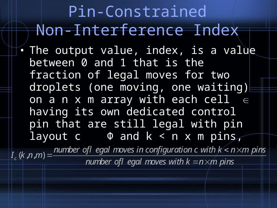
• The output value, index, is a value between 0 and 1 that is the fraction of legal moves for two droplets (one moving, one waiting) on a n x m array with each cell having its own dedicated control pin that are still legal with pin layout c Φ and k < n x m pins,
( , , )c
number of legal moves in configuration c with k n m pinsI k n m
number of legal moves with k n m pins

Examples of PCNI
1
489,3,4 0.324
148I
Layout 11 2 3 8
8 7 6 5
5 4 9 1
2
64(9,3,4) 0.432
148I
3
76(9,3,4) 0.514
148I
Layout 2
1 6 7 1
2 5 8 2
3 4 9 3
Layout 31 4 7 9
7 2 5 8
9 8 3 6

Maximizing PCNI• Qualitatively speaking, better layouts seem to
loosely obey two principles:– Spread out placement of pins used multiple times– Place multiply-used pins on cells that have fewer neighbors
(e.g. sides and corners)
• Most assays cannot even be completed as scheduled on pin-constrained arrays (functionality problem, not just throughput)
Virtual Partitioning
• Alternative: partition array into regions inwhich only one droplet will be present atany given time
• With partitioned array, # of droplets that can be transported simultaneously without interference is equal to the number of partitions since partitions do not share any control pins (no interference between partitions possible)
• Fluidic constraints still must be satisfied so that inadvertent mixing does not occur.

1 6 3 8 1
2 7 4 9 2
3 8 5 10 3
4 9 2 7 4
5 10 1 6 5
Non-partitioned
I(10,5,5) = 0.2626
Dynamically divide the array into two partitions such that two droplets will never have the potential to interfere
- Only the fluidic constraints need to be considered
1 2 3 6 7
4 5 1 8 9
2 3 4 10 6
5 1 6 7 8
4 2 8 9 10
Yellow Partition: pins 1-5Green Partition: pins 6-10
I(10,5,5) = 0.4041
Examples of Partitioned Arrays

15x15 array with depiction of droplet paths for multiplexed glucose and lactase assays
Multiplexed Bioassays

With 225 control pins (i.e., fully addressable array), schedule was devised to be:
Step/Time Elapsed (seconds)
Operation
Step 1 / 0 Sample 2 and reagent 2 start to move towards the mixer.
Step 2 / 0.8 Sample 2 and reagent 2 begin to mix together and turn around in the 23-array mixer.
Step 3 / 6.0 Sample1 and reagent 1 start to move towards the mixer. Sample 2 and reagent 2 continue the mixing.
Step 4 / 6.8 Sample 2 and reagent 2 finish the mixing and product 2 leaves the mixer to optical detection location 2. Sample 1 and reagent 1 begin to mix in the 23-array mixer.
Step 5 / 12.8 Sample 1 and reagent 1 finish the mixing and product 1 leaves the mixer to the optical detection location 1. Product 2 continues the absorbance detection.
Step 6 / 19.8 Product 2 finishes optical detection and leaves the array to the waste reservoir. Product 1 continues the absorbance detection.
Step 7 / 25.8 Product 1 finishes optical detection and leaves the array to the waste reservoir. One procedure of the multiplexed bioassays ends.
Multiplexed Bioassays

Can reduce input bandwidth while maintaining same throughput (true of most assays). Only need 5 partitions and 25 pins (11.11% of original input bandwidth).
Throughput would be significantly reduced with a non-partitioned array with k ≥ 25 and in many instances, assay cannot be finished. In many instances, substantial rerouting and rescheduling is required to finish the assay.
Multiplexed Bioassays

For pin-constrained arrays, virtual partitioning reduces interference when arrays are used randomly, and removes
interference when one droplet per partition rule is followed.
For pin-constrained arrays, virtual partitioning reduces interference when arrays are used randomly, and removes
interference when one droplet per partition rule is followed.
Partitioning Advantage

Summary
• Addressed an important problems in automating design of DMBs– New design method for pin-constrained digital
microfluidics involving virtual partitioning to reduce input bandwidth without sacrificing schedule functionality and throughput