Slide titleIn CAPITALS
50 pt
Slide subtitle 32 pt
WCDMA RAN P6
IP Transport
Top right corner for field-mark, customer or partner logotypes. See Best practice for example.
Slide title 40 pt
Slide subtitle 24 pt
Text 24 pt
Bullets level 2-520 pt
Ericsson Internal IP Transport in WCDMA RAN P6 2007-11-022
Contents
Overview Infrastructure aspects O&M transport Network Synchronisation Control Plane transport User Plane transport TNL QoS Node Synchronisation
Top right corner for field-mark, customer or partner logotypes. See Best practice for example.
Slide title 40 pt
Slide subtitle 24 pt
Text 24 pt
Bullets level 2-520 pt
Ericsson Internal IP Transport in WCDMA RAN P6 2007-11-023
Infrastructure aspects
Overview Node configuration
– RNC– RBS
Network ET-MFX IP Addressing/VLAN
Top right corner for field-mark, customer or partner logotypes. See Best practice for example.
Slide title 40 pt
Slide subtitle 24 pt
Text 24 pt
Bullets level 2-520 pt
Ericsson Internal IP Transport in WCDMA RAN P6 2007-11-024
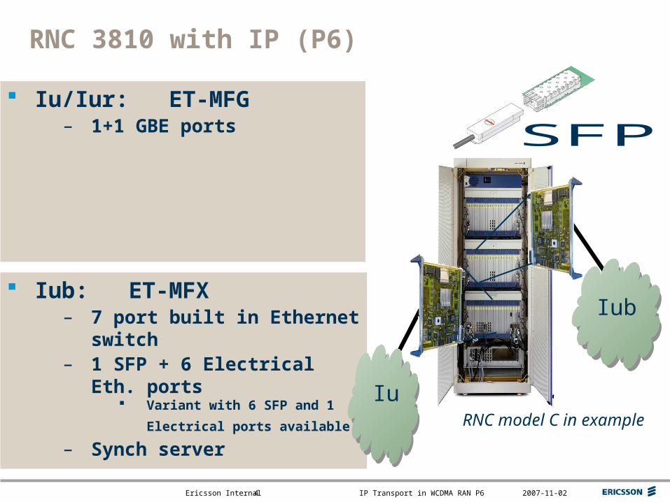
RNC 3810 with IP (P6)
RNC model C in example
Iub
Iu/Iur: ET-MFG– 1+1 GBE ports
Iub: ET-MFX– 7 port built in Ethernet switch– 1 SFP + 6 Electrical Eth. ports
Variant with 6 SFP and 1
Electrical ports available – Synch server Iu

Top right corner for field-mark, customer or partner logotypes. See Best practice for example.
Slide title 40 pt
Slide subtitle 24 pt
Text 24 pt
Bullets level 2-520 pt
Ericsson Internal IP Transport in WCDMA RAN P6 2007-11-025
RBS with IP (P6)ET-MFX
For Iub and O&M IP/Ethernet interface with optional
Ethernet switch 1 SFP + 6 Electrical Eth. ports Synch client
3206 in example
Top right corner for field-mark, customer or partner logotypes. See Best practice for example.
Slide title 40 pt
Slide subtitle 24 pt
Text 24 pt
Bullets level 2-520 pt
Ericsson Internal IP Transport in WCDMA RAN P6 2007-11-026
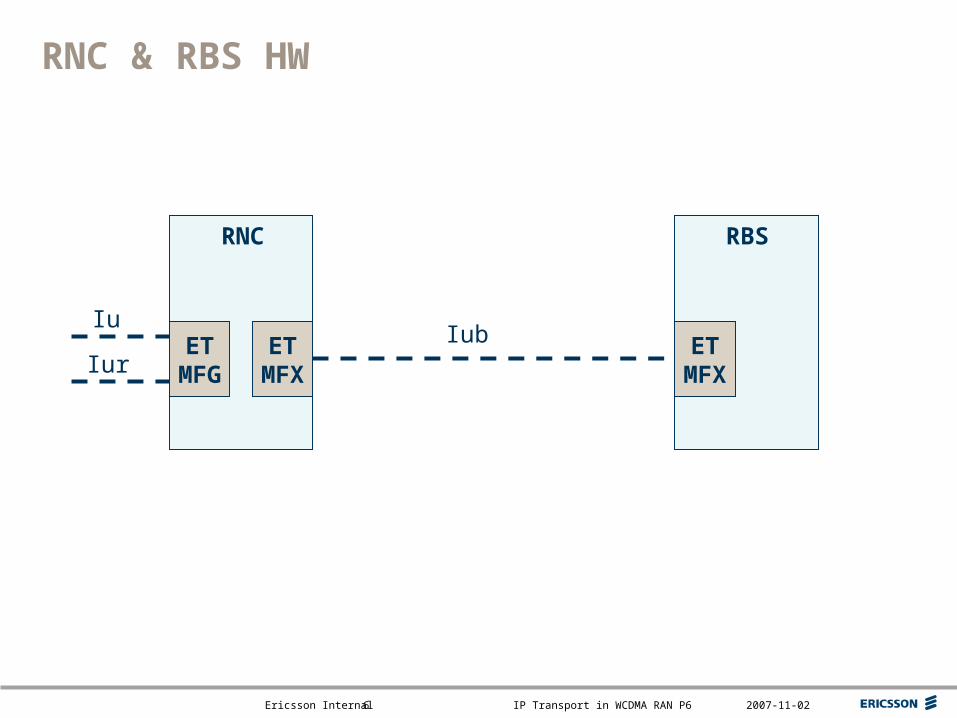
RNC & RBS HW
RNC RBS
ETMFX
ETMFX
ETMFG
IubIur
Iu
Top right corner for field-mark, customer or partner logotypes. See Best practice for example.
Slide title 40 pt
Slide subtitle 24 pt
Text 24 pt
Bullets level 2-520 pt
Ericsson Internal IP Transport in WCDMA RAN P6 2007-11-027
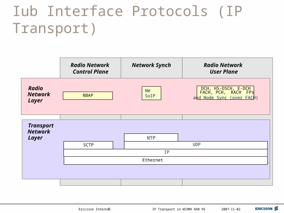
Iub Interface Protocols (IP Transport)
DCH, HS-DSCH, E-DCH FACH, PCH, RACH FPs
NBAP
TransportNetworkLayer
RadioNetworkLayer
Radio Network Control Plane
Network Synch Radio Network User Plane
NW SoIP
Ethernet
and Node Sync (over FACH)
IP
UDPSCTP
NTP
Top right corner for field-mark, customer or partner logotypes. See Best practice for example.
Slide title 40 pt
Slide subtitle 24 pt
Text 24 pt
Bullets level 2-520 pt
Ericsson Internal IP Transport in WCDMA RAN P6 2007-11-028
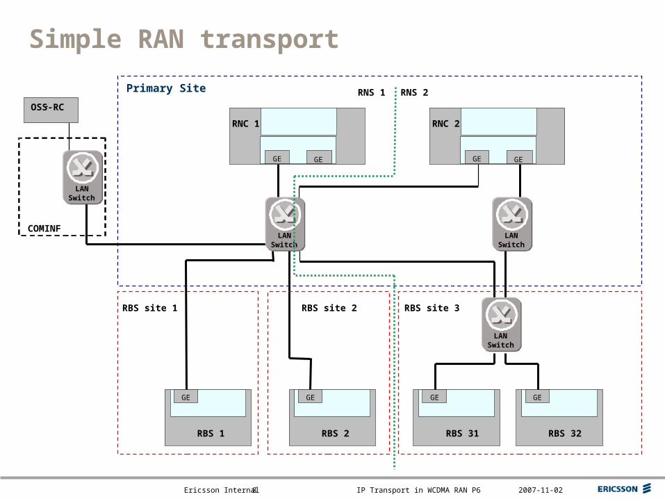
Simple RAN transport
RBS site 1
RNC 1
GE GE
RNC 2
GE GE
RBS 1
GE
RBS 2
GE
RBS 31
GE
RBS 32
GE
XLANSwitch
XLANSwitch
XLANSwitch
COMINF
OSS-RC-
Primary Site
XLANSwitch
RBS site 2 RBS site 3
RNS 1 RNS 2
Top right corner for field-mark, customer or partner logotypes. See Best practice for example.
Slide title 40 pt
Slide subtitle 24 pt
Text 24 pt
Bullets level 2-520 pt
Ericsson Internal IP Transport in WCDMA RAN P6 2007-11-029
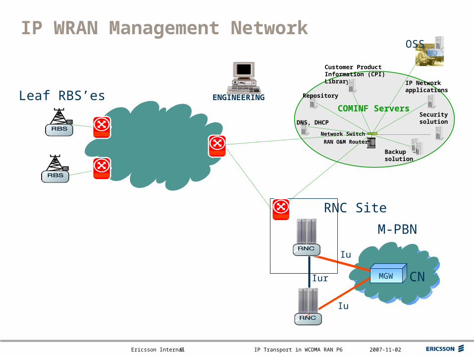
IP Network applications
Security solution
Customer Product Information (CPI) Library
Network Switch
RAN O&M Router
Backup solution
COMINF Servers
OSS
Repository
IP WRAN Management Network
M-PBN
Iur MGW CN
Iu
Iu
RNC Site
Leaf RBS’es
DNS, DHCP
ENGINEERING

Top right corner for field-mark, customer or partner logotypes. See Best practice for example.
Slide title 40 pt
Slide subtitle 24 pt
Text 24 pt
Bullets level 2-520 pt
Ericsson Internal IP Transport in WCDMA RAN P6 2007-11-0210
IP associations on Iub
RNCRBS
RBS
RBS
UP/SoIP H
CP H
UP/SoIP H
Sign H
IP network
Traffic domain
A1.B1.C1.D1
O&M hostO&M host
O&M RAN domain
O&M Network
OSS/Servers
Core NetworkA2.B2.C2.D2
1 per ET
1 per MP
Top right corner for field-mark, customer or partner logotypes. See Best practice for example.
Slide title 40 pt
Slide subtitle 24 pt
Text 24 pt
Bullets level 2-520 pt
Ericsson Internal IP Transport in WCDMA RAN P6 2007-11-0211
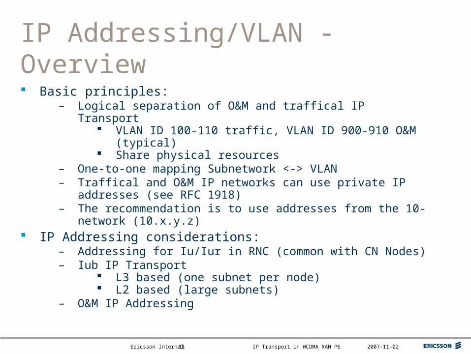
IP Addressing/VLAN - Overview
Basic principles:– Logical separation of O&M and traffical IP Transport
VLAN ID 100-110 traffic, VLAN ID 900-910 O&M (typical) Share physical resources
– One-to-one mapping Subnetwork <-> VLAN– Traffical and O&M IP networks can use private IP addresses (see
RFC 1918)– The recommendation is to use addresses from the 10-network
(10.x.y.z) IP Addressing considerations:
– Addressing for Iu/Iur in RNC (common with CN Nodes)– Iub IP Transport
L3 based (one subnet per node) L2 based (large subnets)
– O&M IP Addressing
Top right corner for field-mark, customer or partner logotypes. See Best practice for example.
Slide title 40 pt
Slide subtitle 24 pt
Text 24 pt
Bullets level 2-520 pt
Ericsson Internal IP Transport in WCDMA RAN P6 2007-11-0213
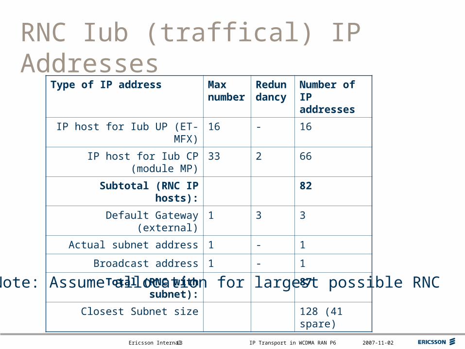
RNC Iub (traffical) IP Addresses
Type of IP address Max number
Redundancy
Number of IP addresses
IP host for Iub UP (ET-MFX) 16 - 16
IP host for Iub CP (module MP) 33 2 66
Subtotal (RNC IP hosts): 82
Default Gateway (external) 1 3 3
Actual subnet address 1 - 1
Broadcast address 1 - 1
Total (RNC with subnet): 87
Closest Subnet size 128 (41 spare)
Note: Assume allocation for largest possible RNC
Top right corner for field-mark, customer or partner logotypes. See Best practice for example.
Slide title 40 pt
Slide subtitle 24 pt
Text 24 pt
Bullets level 2-520 pt
Ericsson Internal IP Transport in WCDMA RAN P6 2007-11-0214
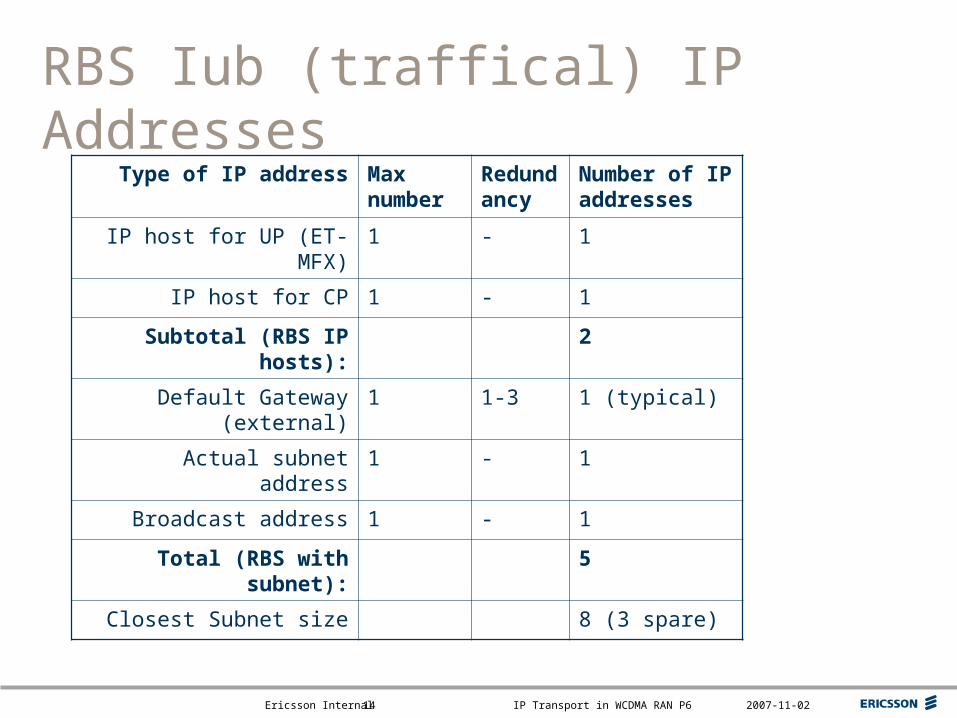
RBS Iub (traffical) IP Addresses
Type of IP address Max number
Redundancy
Number of IP addresses
IP host for UP (ET-MFX) 1 - 1
IP host for CP 1 - 1
Subtotal (RBS IP hosts): 2
Default Gateway (external) 1 1-3 1 (typical)
Actual subnet address 1 - 1
Broadcast address 1 - 1
Total (RBS with subnet): 5
Closest Subnet size 8 (3 spare)
Top right corner for field-mark, customer or partner logotypes. See Best practice for example.
Slide title 40 pt
Slide subtitle 24 pt
Text 24 pt
Bullets level 2-520 pt
Ericsson Internal IP Transport in WCDMA RAN P6 2007-11-0215
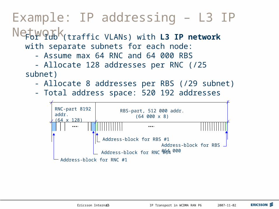
Example: IP addressing – L3 IP Network
RBS-part, 512 000 addr.(64 000 x 8)
RNC-part 8192 addr.(64 x 128)
Address-block for RBS #1
Address-block for RNC #64
For Iub (traffic VLANs) with L3 IP network with separate subnets for each node: - Assume max 64 RNC and 64 000 RBS - Allocate 128 addresses per RNC (/25 subnet) - Allocate 8 addresses per RBS (/29 subnet) - Total address space: 520 192 addresses
Address-block for RBS #64 000
Address-block for RNC #1

Top right corner for field-mark, customer or partner logotypes. See Best practice for example.
Slide title 40 pt
Slide subtitle 24 pt
Text 24 pt
Bullets level 2-520 pt
Ericsson Internal IP Transport in WCDMA RAN P6 2007-11-0216
Example: IP Addressing – L2 IP Network
RNS #1: 2048 addr.
Address-block for RBS #1
Address-block for RNC #2
For Iub (traffic VLANs) with L2 IP Network with one subnet per RNS - Assume max 64 RNS with 1 RNC and connected RBSs - Max 82 addresses per RNC and 2 addresses per RBS - Allocate 2048 addresses per RNS (/21 subnet) - Will be enough for close to 1000 RBS nodes per RNS - Total address space:131 072 addresses
Address-block for RNC #1
RNS #2: 2048 addr. RNS #64: 2048 addr.
Note: Reparenting require reconfiguration of (traffical) IP addresses in RBS
Top right corner for field-mark, customer or partner logotypes. See Best practice for example.
Slide title 40 pt
Slide subtitle 24 pt
Text 24 pt
Bullets level 2-520 pt
Ericsson Internal IP Transport in WCDMA RAN P6 2007-11-0217
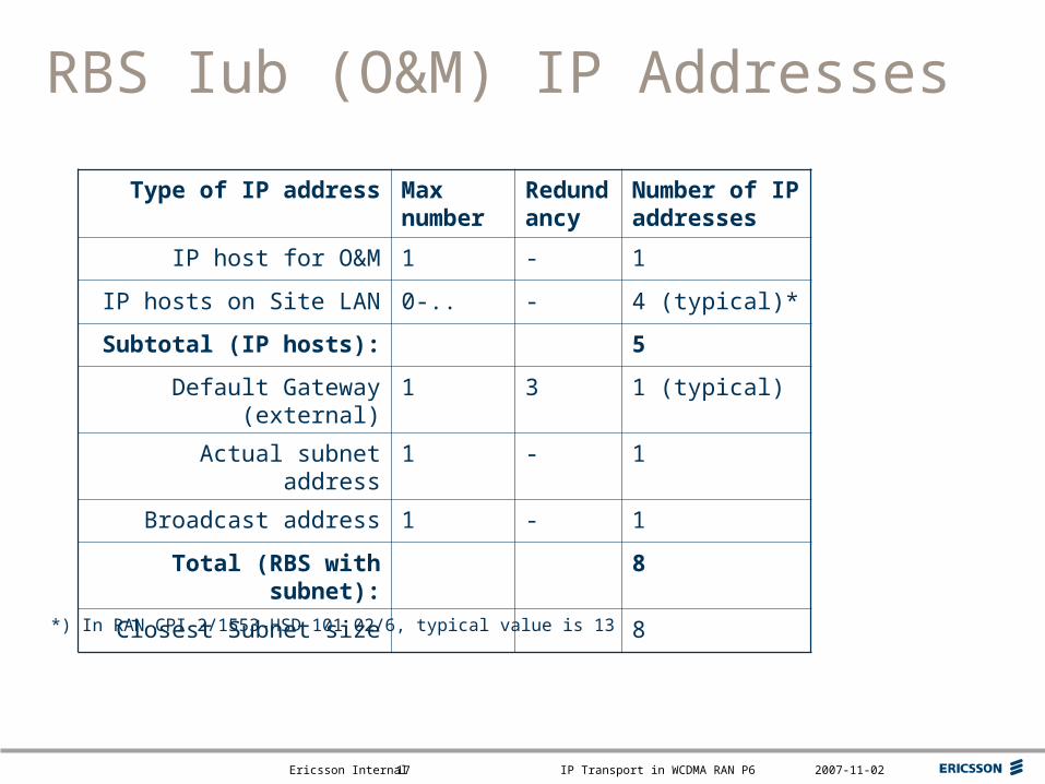
RBS Iub (O&M) IP Addresses
Type of IP address Max number
Redundancy
Number of IP addresses
IP host for O&M 1 - 1
IP hosts on Site LAN 0-.. - 4 (typical)*
Subtotal (IP hosts): 5
Default Gateway (external) 1 3 1 (typical)
Actual subnet address 1 - 1
Broadcast address 1 - 1
Total (RBS with subnet): 8
Closest Subnet size 8
*) In RAN CPI 2/1553-HSD 101 02/6, typical value is 13
Top right corner for field-mark, customer or partner logotypes. See Best practice for example.
Slide title 40 pt
Slide subtitle 24 pt
Text 24 pt
Bullets level 2-520 pt
Ericsson Internal IP Transport in WCDMA RAN P6 2007-11-0218
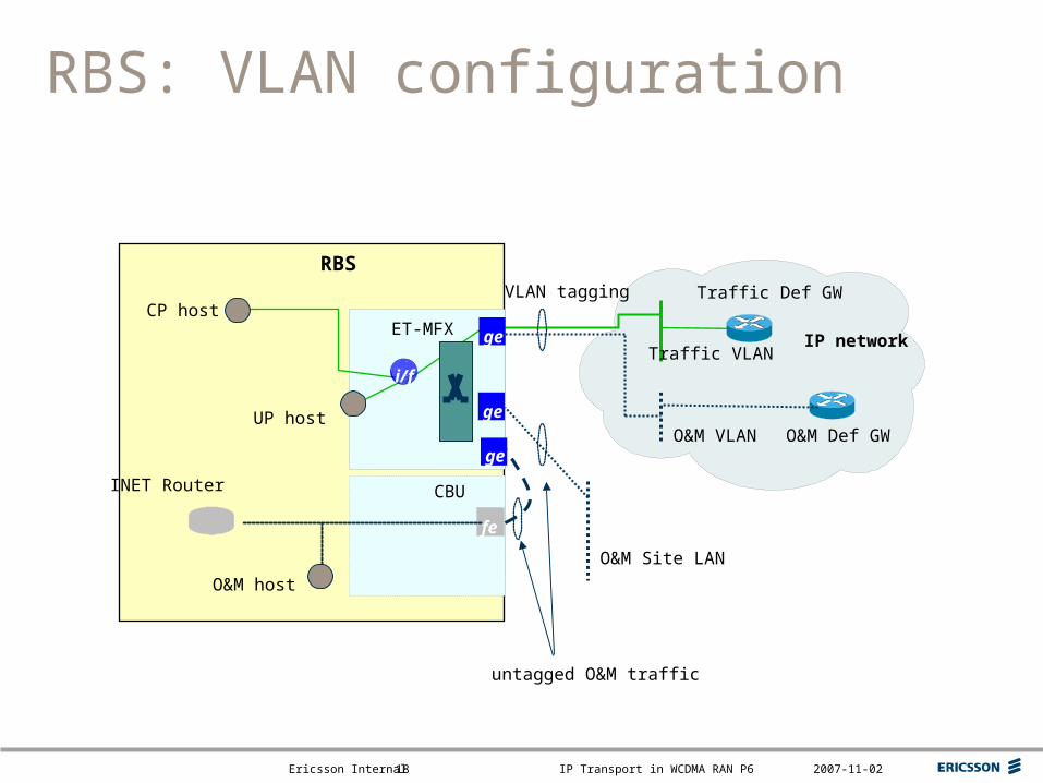
IP network
RBS: VLAN configuration
ET-MFX
Traffic VLAN
O&M VLANgeUP host
CP host
CBU
VLAN tagging
INET Router
O&M Site LAN
untagged O&M traffic
fe
O&M host
RBSTraffic Def GW
O&M Def GW
i/f
ge
ge
Top right corner for field-mark, customer or partner logotypes. See Best practice for example.
Slide title 40 pt
Slide subtitle 24 pt
Text 24 pt
Bullets level 2-520 pt
Ericsson Internal IP Transport in WCDMA RAN P6 2007-11-0219
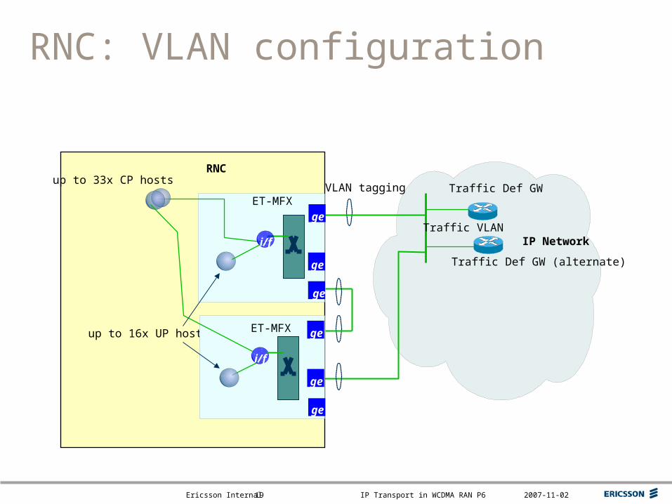
IP Network
RNC: VLAN configuration
ET-MFX
Traffic VLAN
ge
up to 16x UP hosts
up to 33x CP hostsVLAN tagging
RNC
Traffic Def GW
ge
ET-MFX
ge
i/f
ge
i/f
ge
ge
Traffic Def GW (alternate)
Top right corner for field-mark, customer or partner logotypes. See Best practice for example.
Slide title 40 pt
Slide subtitle 24 pt
Text 24 pt
Bullets level 2-520 pt
Ericsson Internal IP Transport in WCDMA RAN P6 2007-11-0220
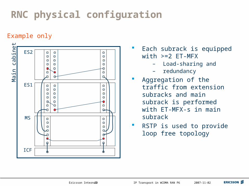
RNC physical configuration
Each subrack is equipped with >=2 ET-MFX
– Load-sharing and– redundancy
Aggregation of the traffic from extension subracks and main subrack is performed with ET-MFX-s in main subrack
RSTP is used to provide loop free topology
Mai
n ca
bine
t
ES2
ICF
MS
ES1
Example only
Top right corner for field-mark, customer or partner logotypes. See Best practice for example.
Slide title 40 pt
Slide subtitle 24 pt
Text 24 pt
Bullets level 2-520 pt
Ericsson Internal IP Transport in WCDMA RAN P6 2007-11-0221
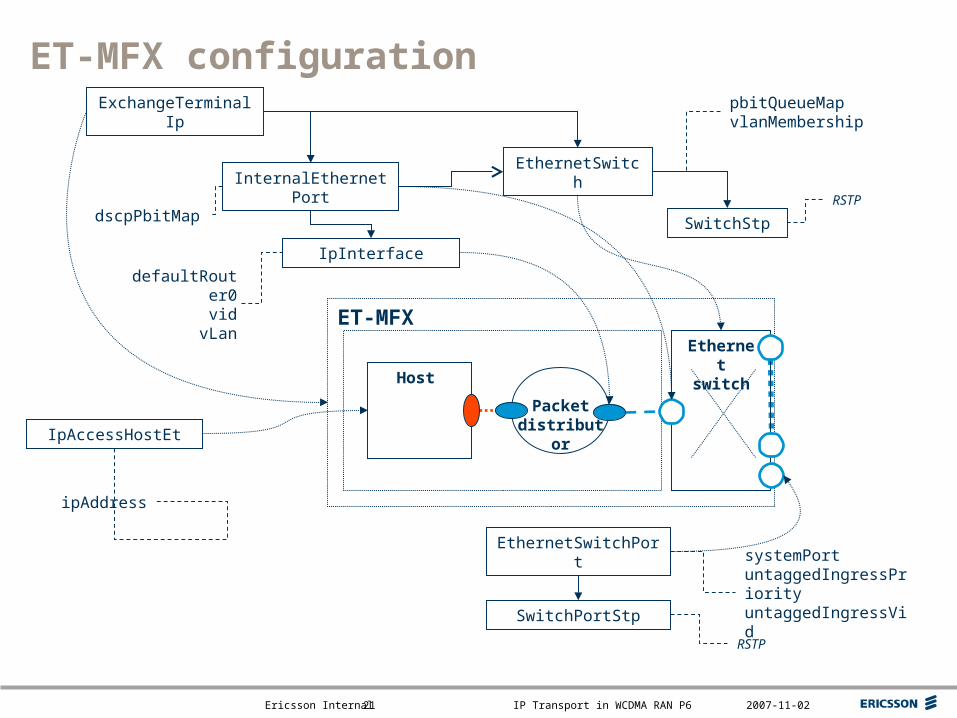
ET-MFX configuration
Packet distributor
ET-MFX
Host
Ethernet switch
EthernetSwitchPortsystemPortuntaggedIngressPriorityuntaggedIngressVid
InternalEthernetPort
dscpPbitMap
EthernetSwitch
SwitchPortStp
RSTP
SwitchStp
RSTP
ExchangeTerminalIp pbitQueueMapvlanMembership
IpAccessHostEt
IpInterface
defaultRouter0vid
vLan
ipAddress
Top right corner for field-mark, customer or partner logotypes. See Best practice for example.
Slide title 40 pt
Slide subtitle 24 pt
Text 24 pt
Bullets level 2-520 pt
Ericsson Internal IP Transport in WCDMA RAN P6 2007-11-0222
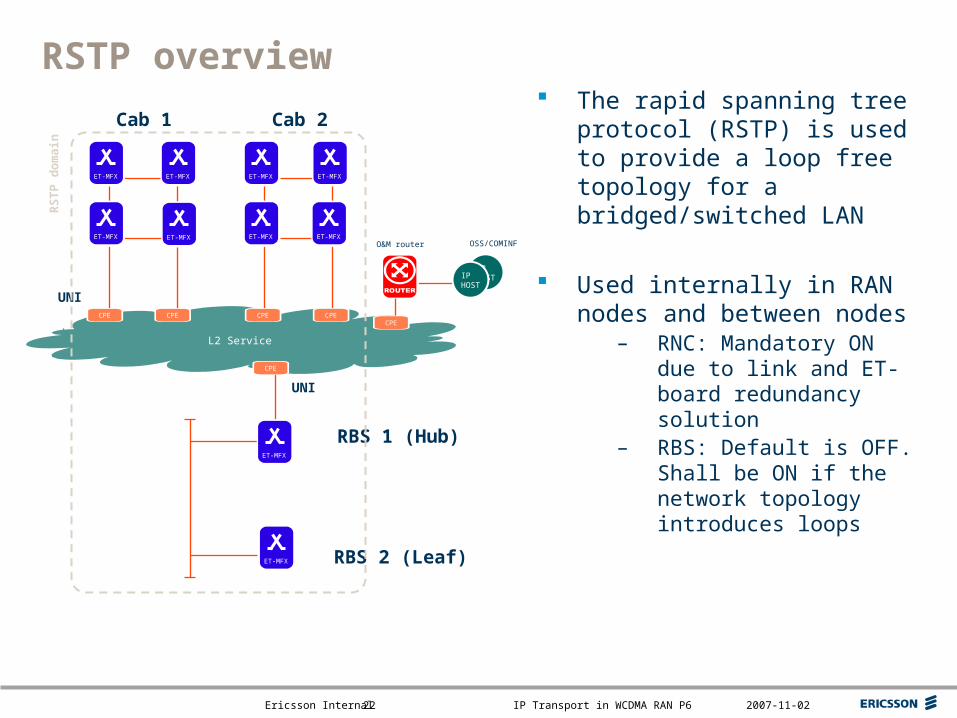
RSTP overview The rapid spanning tree
protocol (RSTP) is used to provide a loop free topology for a bridged/switched LAN
Used internally in RAN nodes and between nodes
– RNC: Mandatory ON due to link and ET-board redundancy solution
– RBS: Default is OFF. Shall be ON if the network topology introduces loops
OSS/COMINF
IPHOSTIP
HOST
RBS 1 (Hub)
RBS 2 (Leaf)
O&M router
Cab 1 Cab 2
CPE CPE CPE CPECPE
CPE
UNI
UNI
RS
TP
do
mai
n
L2 Service
ET-MFX
ET-MFX
ET-MFX ET-MFX
ET-MFX ET-MFX
ET-MFX
ET-MFX
ET-MFX
ET-MFX

Top right corner for field-mark, customer or partner logotypes. See Best practice for example.
Slide title 40 pt
Slide subtitle 24 pt
Text 24 pt
Bullets level 2-520 pt
Ericsson Internal IP Transport in WCDMA RAN P6 2007-11-0223
RSTP – SwitchStp
Attribute Type Default Range Description
bridgeForwardDelay Long 150 40..300 The delay used by the switch before changing to the Forwarding state, in case of a port interoperating with a legacy STP switch.
bridgeHelloTime Long 20 10..100 Interval between periodic transmissions of configuration messages by designated ports.
bridgeMaxAge Long 60 60..400 The maximum time interval before a switch, not receiving any BPDUs, assumes that a network change has occurred
bridgePriority BridgePriority PRIO_32768 Switch priority used by the protocol
This MO is automatically created by the system, when an EthernetSwitch MO is created.

Top right corner for field-mark, customer or partner logotypes. See Best practice for example.
Slide title 40 pt
Slide subtitle 24 pt
Text 24 pt
Bullets level 2-520 pt
Ericsson Internal IP Transport in WCDMA RAN P6 2007-11-0224
RSTP – SwitchPortStp
Attribute Type Default Range Description
actualPathCost Long, readOnly 1..200 000 000 Actual path cost.
configuredPathCost Long 20000 1..200 000 000 Path cost. If manualPathCost is set to true, the actual path cost will be determined by this attribute. If manualPathCost is false, the actual path cost may differ from the value of this attribute.
edgePortBpduGuardTimeOut Long 600 1..65536 The time before an Edge port blocked with BPDU Guard goes unblocked.
edgePortMode EdgePortMode ADMIN_EDGE_OFF
The behavior of an edge port
manualPathCost boolean false Determines the possibility to manually configure the path cost. If this attribute is set to false, the system ignores the configured path cost set in configuredPathCost.
priority Priority PRIO_128 Port priority. The port with the lowest portPriority value will be selected as Root port in the case when more than one port is connected to the Root bridge.
This MO is automatically created by the system, when an EthernetSwitchPort MO is created.
Top right corner for field-mark, customer or partner logotypes. See Best practice for example.
Slide title 40 pt
Slide subtitle 24 pt
Text 24 pt
Bullets level 2-520 pt
Ericsson Internal IP Transport in WCDMA RAN P6 2007-11-0225
O&M transport
Overview Implementation Configuration
Top right corner for field-mark, customer or partner logotypes. See Best practice for example.
Slide title 40 pt
Slide subtitle 24 pt
Text 24 pt
Bullets level 2-520 pt
Ericsson Internal IP Transport in WCDMA RAN P6 2007-11-0226
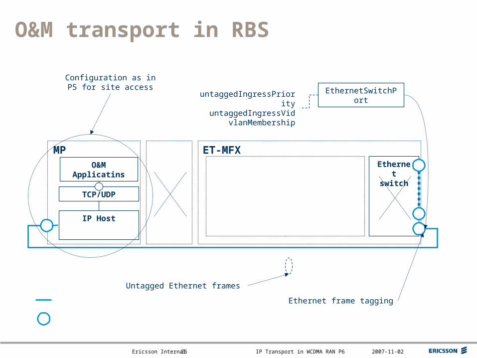
IP Host
O&M transport in RBS
ET-MFXMPEthernet switch
TCP/UDP
O&M Applicatins
Configuration as in P5 for site access EthernetSwitchPortuntaggedIngressPriority
untaggedIngressVidvlanMembership
Untagged Ethernet frames
Ethernet frame tagging
Top right corner for field-mark, customer or partner logotypes. See Best practice for example.
Slide title 40 pt
Slide subtitle 24 pt
Text 24 pt
Bullets level 2-520 pt
Ericsson Internal IP Transport in WCDMA RAN P6 2007-11-0227
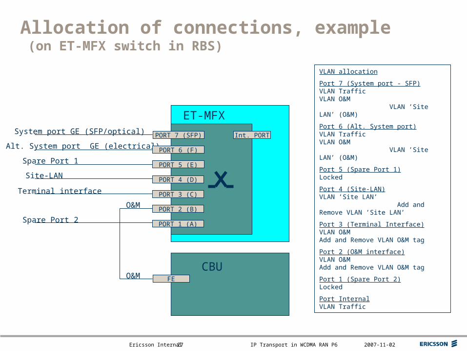
Allocation of connections, example (on ET-MFX switch in RBS)
PORT 7 (SFP)
ET-MFX
CBU
Int. PORT
FE
System port GE (SFP/optical)
Alt. System port GE (electrical)
Terminal interface
Site-LAN
Spare Port 2
Spare Port 1
VLAN allocation
Port 7 (System port - SFP)VLAN TrafficVLAN O&M VLAN ’Site LAN’ (O&M)
Port 6 (Alt. System port)VLAN TrafficVLAN O&M VLAN ’Site LAN’ (O&M)
Port 5 (Spare Port 1)Locked
Port 4 (Site-LAN)VLAN ’Site LAN’ Add and Remove VLAN ’Site LAN’
Port 3 (Terminal Interface)VLAN O&MAdd and Remove VLAN O&M tag
Port 2 (O&M interface)VLAN O&MAdd and Remove VLAN O&M tag
Port 1 (Spare Port 2)Locked
Port InternalVLAN Traffic
O&M
O&M
PORT 6 (F)
PORT 5 (E)
PORT 4 (D)
PORT 3 (C)
PORT 2 (B)
PORT 1 (A)
Top right corner for field-mark, customer or partner logotypes. See Best practice for example.
Slide title 40 pt
Slide subtitle 24 pt
Text 24 pt
Bullets level 2-520 pt
Ericsson Internal IP Transport in WCDMA RAN P6 2007-11-0228
Network Synchronisation
Overview Protocol stack Signalling Implementation Algorithm principles Configuration

Top right corner for field-mark, customer or partner logotypes. See Best practice for example.
Slide title 40 pt
Slide subtitle 24 pt
Text 24 pt
Bullets level 2-520 pt
Ericsson Internal IP Transport in WCDMA RAN P6 2007-11-0229
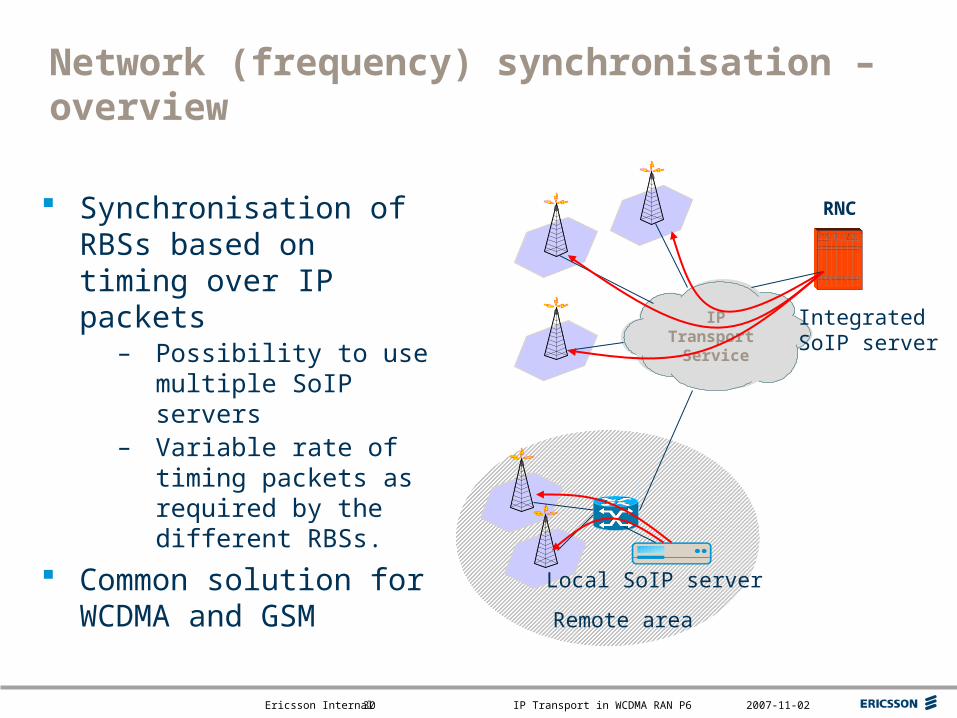
Network (frequency) synchronisation – overview
RBS need to maintain a stable controlled radio frequency in the air interface.
– +/- 50ppb for a macro-cell RBS (25.104)
Poor synchronisation impacts critical KPIs– Decreases accessability and retainability
For TDM, RBS is synchronised to the transport network.
– +/- 16 ppb accuracy provided by the TDM network.
For IP, alternative methods must be found.– GPS at RBS site– Time stamping of packets
Top right corner for field-mark, customer or partner logotypes. See Best practice for example.
Slide title 40 pt
Slide subtitle 24 pt
Text 24 pt
Bullets level 2-520 pt
Ericsson Internal IP Transport in WCDMA RAN P6 2007-11-0230
Network (frequency) synchronisation – overview
Synchronisation of RBSs based on timing over IP packets
– Possibility to use multiple SoIP servers
– Variable rate of timing packets as required by the different RBSs.
Common solution for WCDMA and GSM
IPTransport
Service
RNC
Remote area
IntegratedSoIP server
Local SoIP server
Top right corner for field-mark, customer or partner logotypes. See Best practice for example.
Slide title 40 pt
Slide subtitle 24 pt
Text 24 pt
Bullets level 2-520 pt
Ericsson Internal IP Transport in WCDMA RAN P6 2007-11-0231
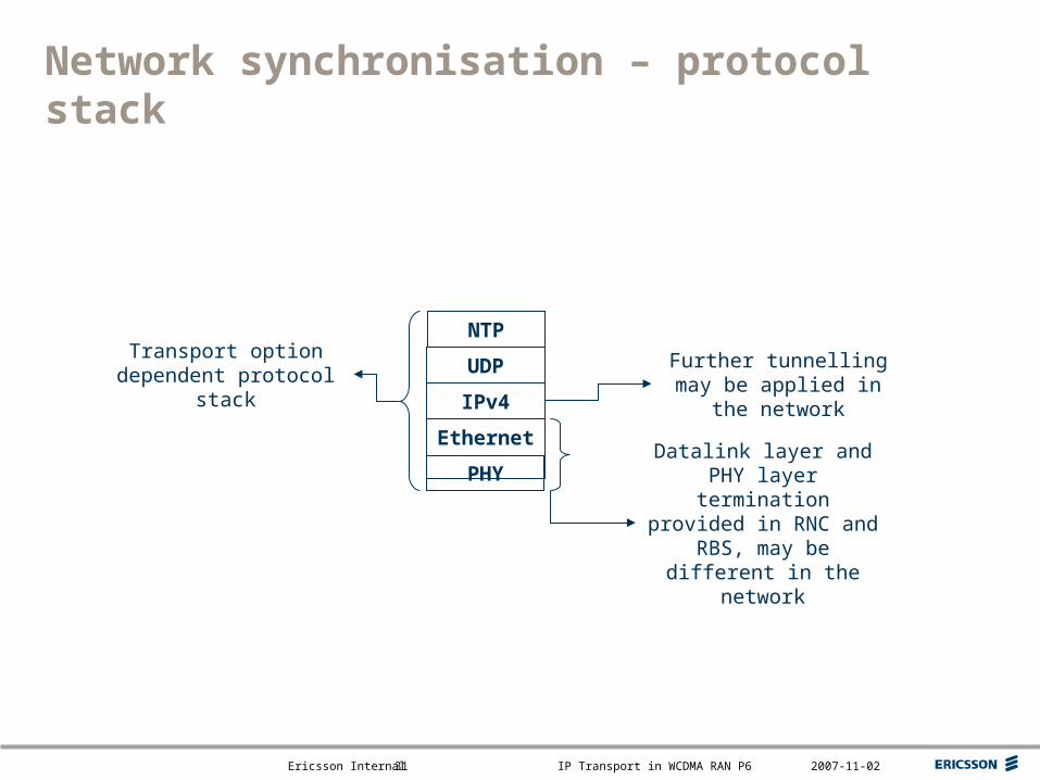
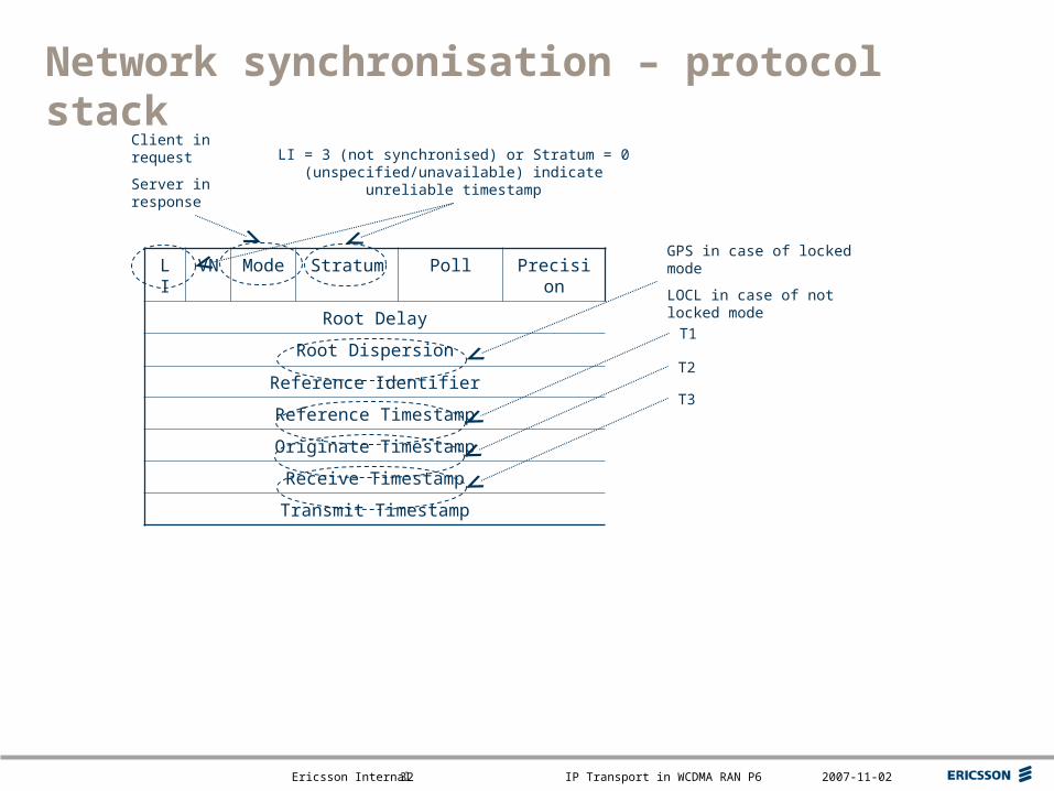
Network synchronisation – protocol stack
NTP
UDP
IPv4
Ethernet
PHYDatalink layer and PHY
layer termination provided in RNC and RBS, may be
different in the network
Further tunnelling may be applied in the network
Transport option dependent protocol stack
Top right corner for field-mark, customer or partner logotypes. See Best practice for example.
Slide title 40 pt
Slide subtitle 24 pt
Text 24 pt
Bullets level 2-520 pt
Ericsson Internal IP Transport in WCDMA RAN P6 2007-11-0232
Network synchronisation – protocol stack
LI VN Mode Stratum Poll Precision
Root Delay
Root Dispersion
Reference Identifier
Reference Timestamp
Originate Timestamp
Receive Timestamp
Transmit Timestamp
Client in request
Server in response
GPS in case of locked mode
LOCL in case of not locked mode
LI = 3 (not synchronised) or Stratum = 0 (unspecified/unavailable) indicate unreliable timestamp
T1
T2
T3
Top right corner for field-mark, customer or partner logotypes. See Best practice for example.
Slide title 40 pt
Slide subtitle 24 pt
Text 24 pt
Bullets level 2-520 pt
Ericsson Internal IP Transport in WCDMA RAN P6 2007-11-0233
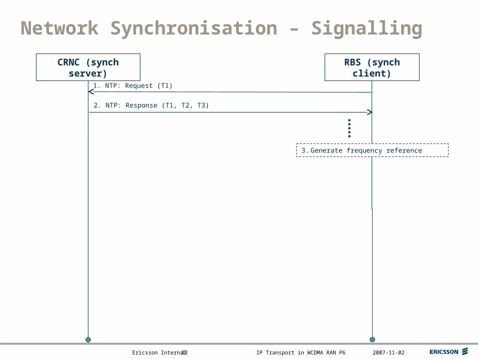
1. NTP: Request (T1)
Network Synchronisation – Signalling
2. NTP: Response (T1, T2, T3)
CRNC (synch server) RBS (synch client)
3. Generate frequency reference
Top right corner for field-mark, customer or partner logotypes. See Best practice for example.
Slide title 40 pt
Slide subtitle 24 pt
Text 24 pt
Bullets level 2-520 pt
Ericsson Internal IP Transport in WCDMA RAN P6 2007-11-0234
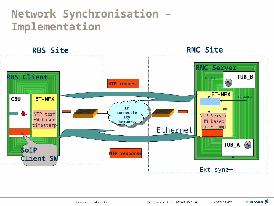
Network Synchronisation – Implementation
ET-MFX
NTP termHW basedtimestamp
Ethernet
RNC Site
Ext sync
TUB_A
NTP ServerHW basedtimestamp
ET-MFX
48.6MHz
TUB_B19.44MHz
19.44MHz
IP connectivity Network
IP connectivity Network
RBS Site
CBU
NTP request
NTP response
RBS ClientRNC Server
SoIPClient SW
Top right corner for field-mark, customer or partner logotypes. See Best practice for example.
Slide title 40 pt
Slide subtitle 24 pt
Text 24 pt
Bullets level 2-520 pt
Ericsson Internal IP Transport in WCDMA RAN P6 2007-11-0235
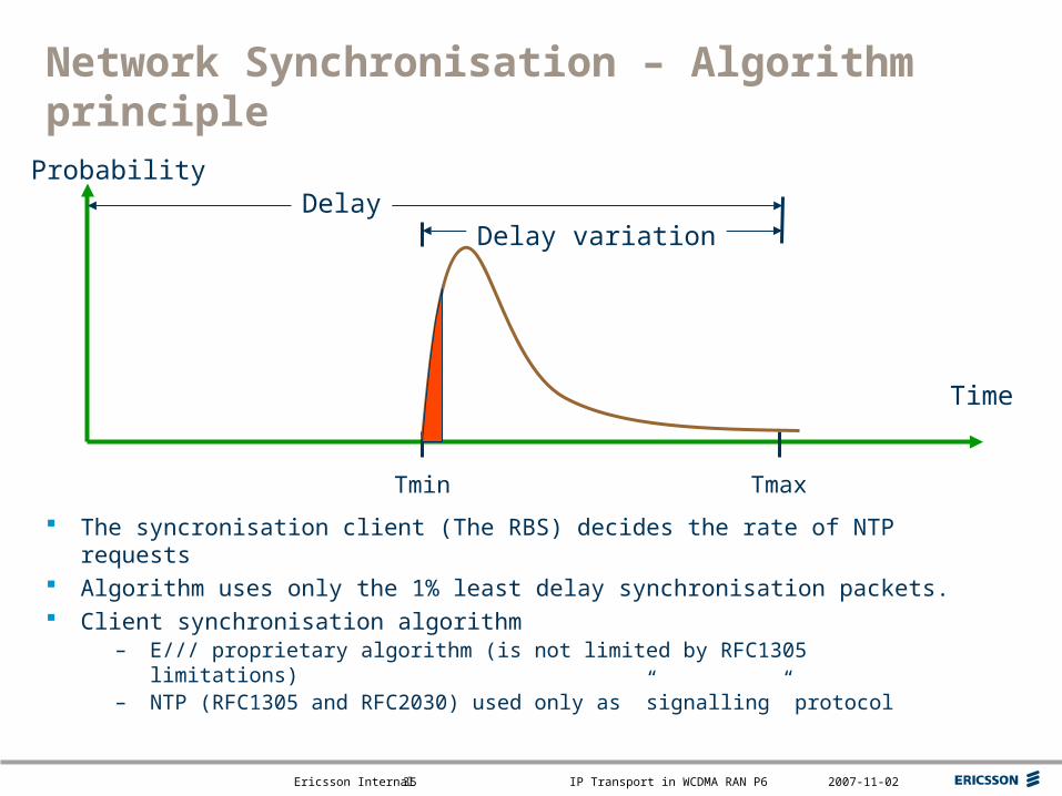
Network Synchronisation – Algorithm principle
Time
Probability
Tmin Tmax
DelayDelay variation
The syncronisation client (The RBS) decides the rate of NTP requests
Algorithm uses only the 1% least delay synchronisation packets. Client synchronisation algorithm
– E/// proprietary algorithm (is not limited by RFC1305 limitations)– NTP (RFC1305 and RFC2030) used only as ”signalling” protocol
Top right corner for field-mark, customer or partner logotypes. See Best practice for example.
Slide title 40 pt
Slide subtitle 24 pt
Text 24 pt
Bullets level 2-520 pt
Ericsson Internal IP Transport in WCDMA RAN P6 2007-11-0236
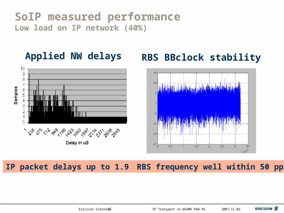
SoIP measured performanceLow load on IP network (40%)
IP packet delays up to 1.9 ms
Applied NW delays
RBS frequency well within 50 ppb
RBS BBclock stability
Top right corner for field-mark, customer or partner logotypes. See Best practice for example.
Slide title 40 pt
Slide subtitle 24 pt
Text 24 pt
Bullets level 2-520 pt
Ericsson Internal IP Transport in WCDMA RAN P6 2007-11-0237
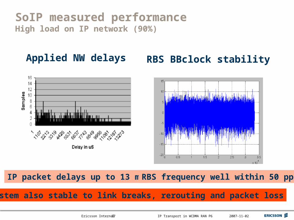
SoIP measured performanceHigh load on IP network (90%)
IP packet delays up to 13 ms
Applied NW delays
RBS frequency well within 50 ppb
RBS BBclock stability
System also stable to link breaks, rerouting and packet loss
Top right corner for field-mark, customer or partner logotypes. See Best practice for example.
Slide title 40 pt
Slide subtitle 24 pt
Text 24 pt
Bullets level 2-520 pt
Ericsson Internal IP Transport in WCDMA RAN P6 2007-11-0238
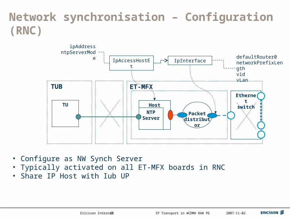
Network synchronisation – Configuration (RNC)
NTP Server
Packet distributor
ET-MFX
Host
Ethernet switch
IpAccessHostEt IpInterface
ipAddressntpServerMode
TUB
TU
defaultRouter0networkPrefixLengthvidvLan
• Configure as NW Synch Server• Typically activated on all ET-MFX boards in RNC• Share IP Host with Iub UP
Top right corner for field-mark, customer or partner logotypes. See Best practice for example.
Slide title 40 pt
Slide subtitle 24 pt
Text 24 pt
Bullets level 2-520 pt
Ericsson Internal IP Transport in WCDMA RAN P6 2007-11-0239
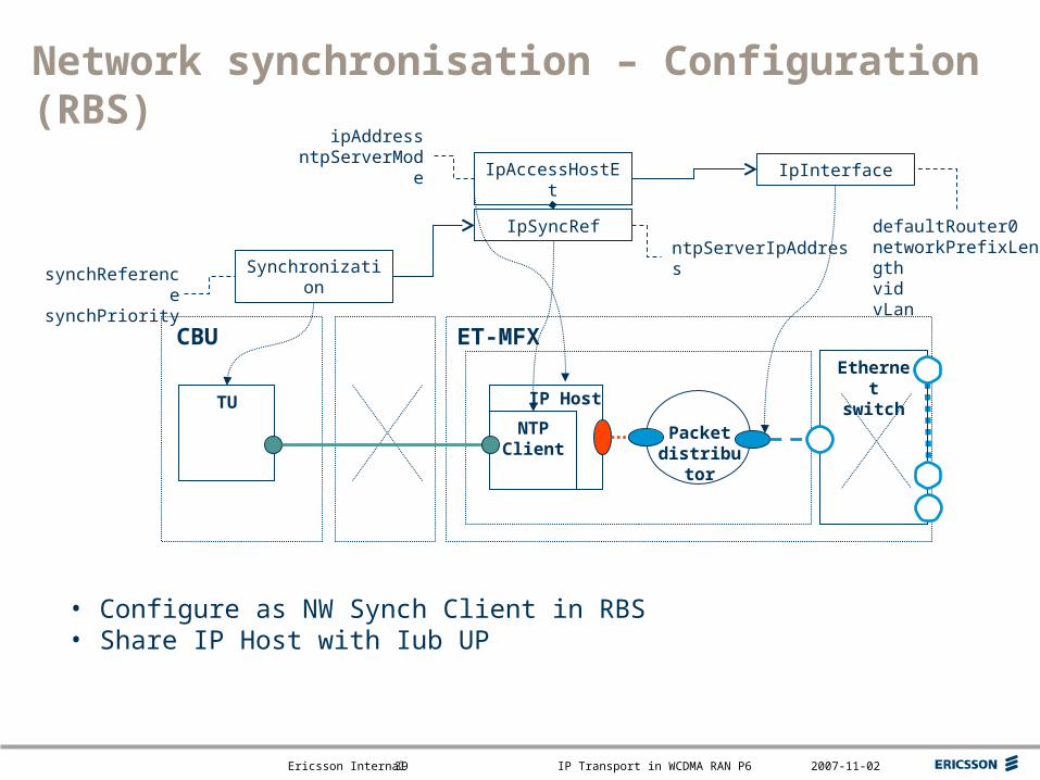
Network synchronisation – Configuration (RBS)
Packet distributor
ET-MFX
IP Host
Ethernet switch
CBU
TU
IpAccessHostEt IpInterface
ipAddressntpServerMode
IpSyncRefntpServerIpAddress
SynchronizationsynchReferencesynchPriority
defaultRouter0networkPrefixLengthvidvLan
• Configure as NW Synch Client in RBS• Share IP Host with Iub UP
NTP Client
Top right corner for field-mark, customer or partner logotypes. See Best practice for example.
Slide title 40 pt
Slide subtitle 24 pt
Text 24 pt
Bullets level 2-520 pt
Ericsson Internal IP Transport in WCDMA RAN P6 2007-11-0240
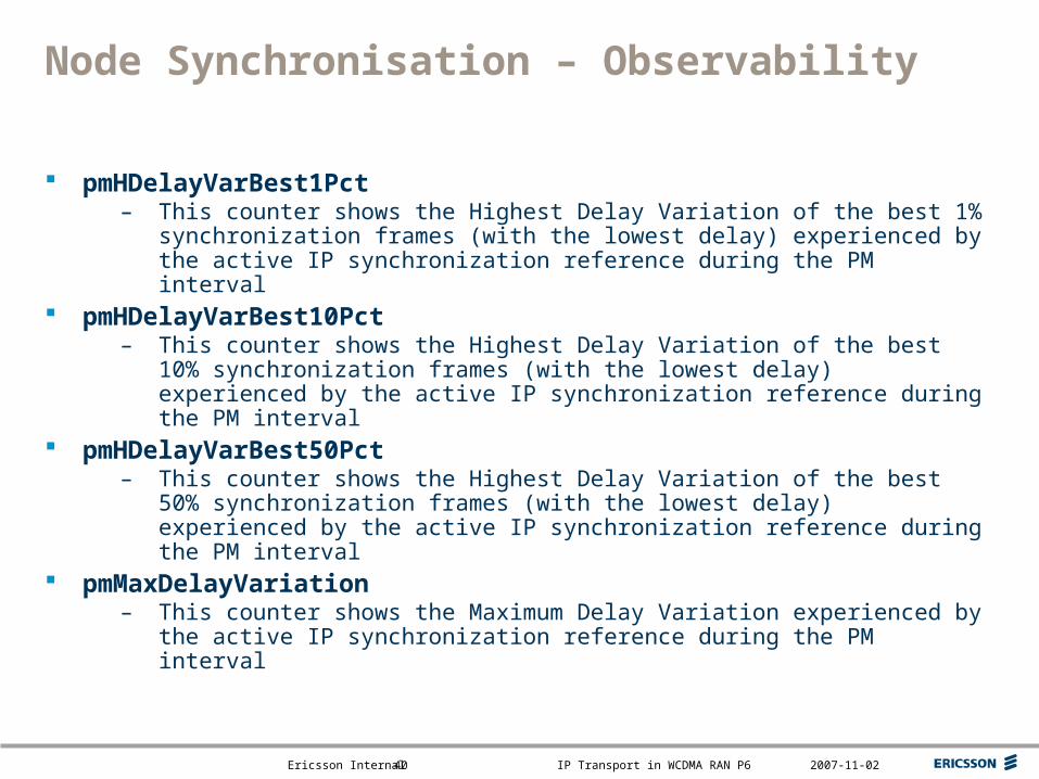
Node Synchronisation – Observability
pmHDelayVarBest1Pct – This counter shows the Highest Delay Variation of the best 1%
synchronization frames (with the lowest delay) experienced by the active IP synchronization reference during the PM interval
pmHDelayVarBest10Pct– This counter shows the Highest Delay Variation of the best 10%
synchronization frames (with the lowest delay) experienced by the active IP synchronization reference during the PM interval
pmHDelayVarBest50Pct – This counter shows the Highest Delay Variation of the best 50%
synchronization frames (with the lowest delay) experienced by the active IP synchronization reference during the PM interval
pmMaxDelayVariation – This counter shows the Maximum Delay Variation experienced by the
active IP synchronization reference during the PM interval

Top right corner for field-mark, customer or partner logotypes. See Best practice for example.
Slide title 40 pt
Slide subtitle 24 pt
Text 24 pt
Bullets level 2-520 pt
Ericsson Internal IP Transport in WCDMA RAN P6 2007-11-0241
Control Plane transport
Supported transport options Protocol stack Transport Bearer Establishment Transport Bearer termination Configuration

Top right corner for field-mark, customer or partner logotypes. See Best practice for example.
Slide title 40 pt
Slide subtitle 24 pt
Text 24 pt
Bullets level 2-520 pt
Ericsson Internal IP Transport in WCDMA RAN P6 2007-11-0242
Control Plane transport – overview
CRNC
RBS_1
SCTP/IP transport
RBS_2
USAAL/ATM transport
RBS may be ATM only (RBS_2) or IP only (RBS_1)
One Iub supports one transport option
RNC supports both Iub transport options (on different interface instances)
Each Iub has two (2) transport bearers for NBAP – one for
NBAP-C and one for NBAP-D
Transport bearer in case of IP transport is SCTP association
Top right corner for field-mark, customer or partner logotypes. See Best practice for example.
Slide title 40 pt
Slide subtitle 24 pt
Text 24 pt
Bullets level 2-520 pt
Ericsson Internal IP Transport in WCDMA RAN P6 2007-11-0243
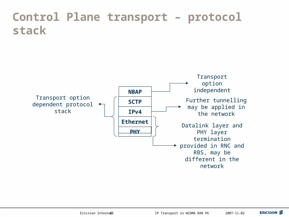
Control Plane transport – protocol stack
NBAP
SCTP
IPv4
Ethernet
PHY
Transport option independent
Datalink layer and PHY layer termination provided in RNC and RBS, may be
different in the network
Further tunnelling may be applied in the network
Transport option dependent protocol stack
Top right corner for field-mark, customer or partner logotypes. See Best practice for example.
Slide title 40 pt
Slide subtitle 24 pt
Text 24 pt
Bullets level 2-520 pt
Ericsson Internal IP Transport in WCDMA RAN P6 2007-11-0244
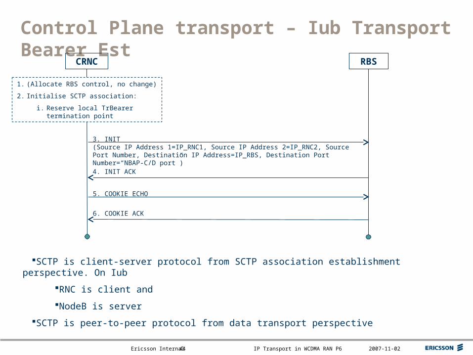
4. INIT ACK
Control Plane transport – Iub Transport Bearer Est
RBS
3. INIT(Source IP Address 1=IP_RNC1, Source IP Address 2=IP_RNC2, Source Port Number, Destination IP Address=IP_RBS, Destination Port Number=“NBAP-C/D port”)
CRNC
1. (Allocate RBS control, no change)
2. Initialise SCTP association:
i. Reserve local TrBearer termination point
6. COOKIE ACK
5. COOKIE ECHO
SCTP is client-server protocol from SCTP association establishment perspective. On Iub
RNC is client and
NodeB is server
SCTP is peer-to-peer protocol from data transport perspective
Top right corner for field-mark, customer or partner logotypes. See Best practice for example.
Slide title 40 pt
Slide subtitle 24 pt
Text 24 pt
Bullets level 2-520 pt
Ericsson Internal IP Transport in WCDMA RAN P6 2007-11-0245
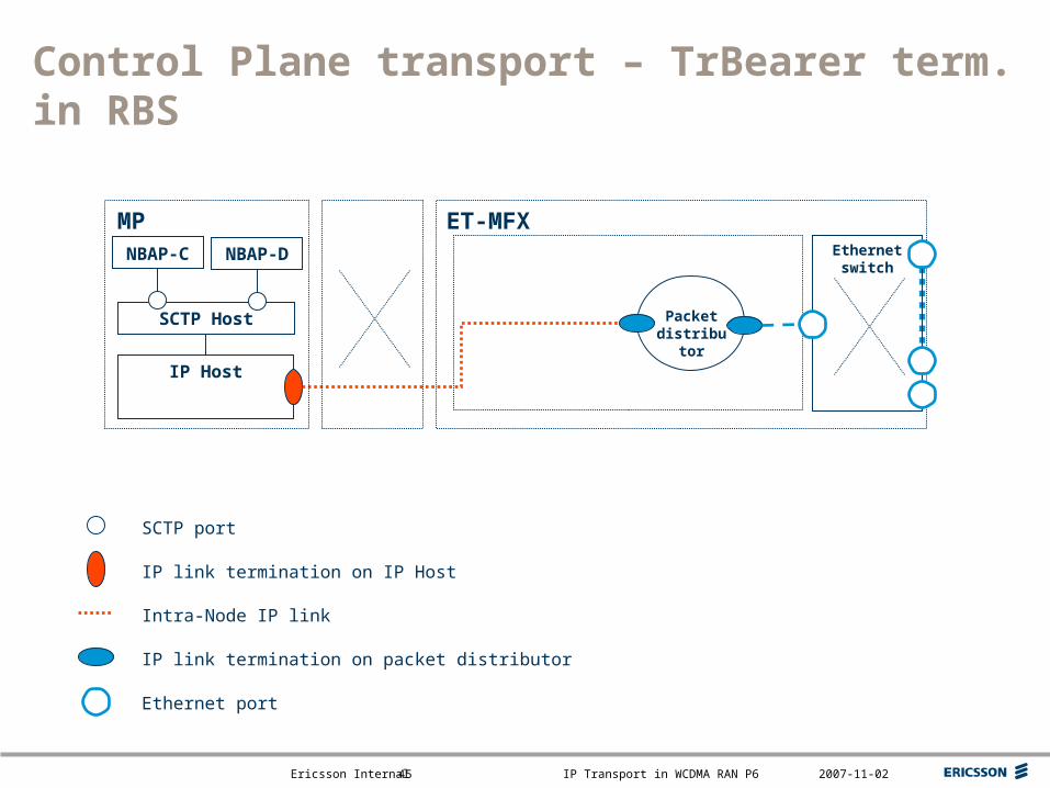
IP Host
Control Plane transport – TrBearer term. in RBS
Packet distributor
ET-MFXMP
IP link termination on IP Host
Intra-Node IP link
IP link termination on packet distributor
Ethernet port
SCTP port
Ethernet switch
SCTP Host
NBAP-C NBAP-D
Top right corner for field-mark, customer or partner logotypes. See Best practice for example.
Slide title 40 pt
Slide subtitle 24 pt
Text 24 pt
Bullets level 2-520 pt
Ericsson Internal IP Transport in WCDMA RAN P6 2007-11-0246
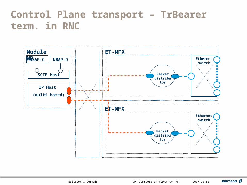
Control Plane transport – TrBearer term. in RNC
IP Host
(multi-homed)
Packet distributor
ET-MFXModule MPEthernet switch
SCTP Host
NBAP-C NBAP-D
Packet distributor
ET-MFXEthernet switch
Top right corner for field-mark, customer or partner logotypes. See Best practice for example.
Slide title 40 pt
Slide subtitle 24 pt
Text 24 pt
Bullets level 2-520 pt
Ericsson Internal IP Transport in WCDMA RAN P6 2007-11-0247
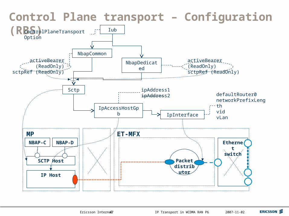
Control Plane transport – Configuration (RBS)
IpAccessHostGpb
IpInterface
controlPlaneTransportOption
activeBearer (ReadOnly)sctpRef (ReadOnly)
Iub
NbapCommon
NbapDedicated
IP Host
Packet distribut
or
ET-MFXMPEthernet switch
SCTP Host
Sctp
activeBearer (ReadOnly)sctpRef (ReadOnly)
ipAddress1ipAddress2 defaultRouter0
networkPrefixLengthvidvLan
NBAP-C NBAP-D
Top right corner for field-mark, customer or partner logotypes. See Best practice for example.
Slide title 40 pt
Slide subtitle 24 pt
Text 24 pt
Bullets level 2-520 pt
Ericsson Internal IP Transport in WCDMA RAN P6 2007-11-0248
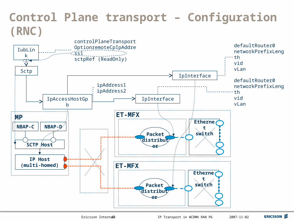
Control Plane transport – Configuration (RNC)
IpAccessHostGpb IpInterface
IubLink
controlPlaneTransportOptionremoteCpIpAddress1sctpRef (ReadOnly)
IP Host(multi-homed)
MP
Packet distributor
ET-MFXEthernet switch
SCTP Host
Sctp
Packet distributor
ET-MFXEthernet switch
IpInterface
defaultRouter0networkPrefixLengthvidvLan
defaultRouter0networkPrefixLengthvidvLan
ipAddress1ipAddress2
NBAP-C NBAP-D
Top right corner for field-mark, customer or partner logotypes. See Best practice for example.
Slide title 40 pt
Slide subtitle 24 pt
Text 24 pt
Bullets level 2-520 pt
Ericsson Internal IP Transport in WCDMA RAN P6 2007-11-0249
User Plane transport
Supported transport options on Iur and Iub Protocol stack Transport Bearer Establishment
– Transport Bearer identifiers Address formats
– TNL QoS class– Link Characteristics
Transport Bearer termination– RBS– RNC
Configuration
Top right corner for field-mark, customer or partner logotypes. See Best practice for example.
Slide title 40 pt
Slide subtitle 24 pt
Text 24 pt
Bullets level 2-520 pt
Ericsson Internal IP Transport in WCDMA RAN P6 2007-11-0250
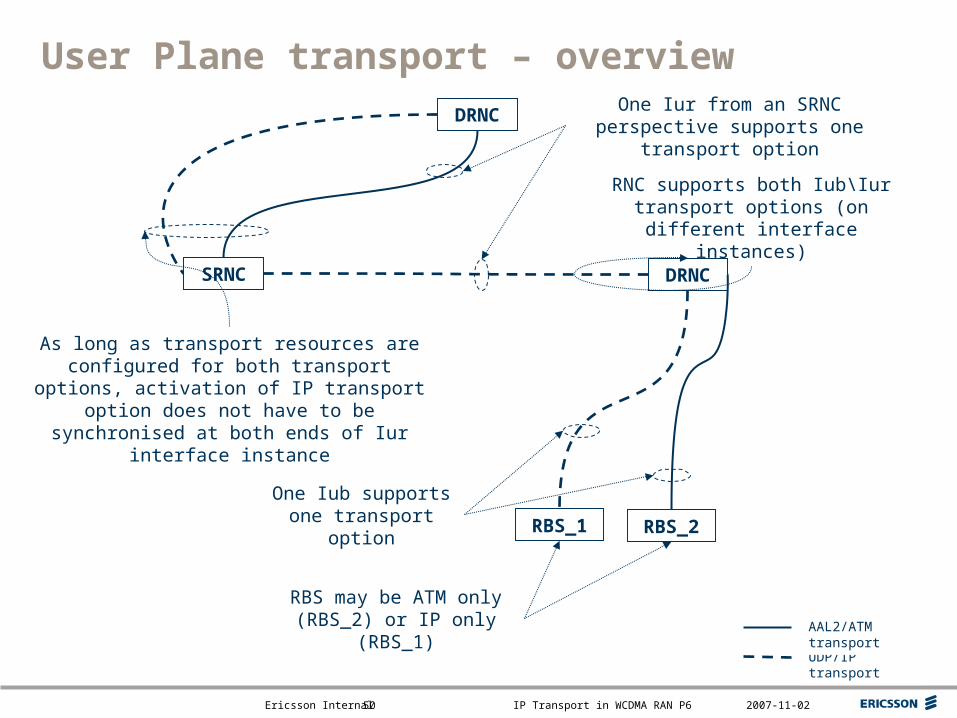
User Plane transport – overview
SRNC DRNC
RBS_1
UDP/IP transport
RBS_2
AAL2/ATM transport
RBS may be ATM only (RBS_2) or IP only (RBS_1)
One Iub supports one transport option
One Iur from an SRNC perspective supports one transport option
DRNC
As long as transport resources are configured for both transport options, activation of IP transport option does not have to be synchronised at both
ends of Iur interface instance
RNC supports both Iub\Iur transport options (on different interface instances)
Top right corner for field-mark, customer or partner logotypes. See Best practice for example.
Slide title 40 pt
Slide subtitle 24 pt
Text 24 pt
Bullets level 2-520 pt
Ericsson Internal IP Transport in WCDMA RAN P6 2007-11-0251
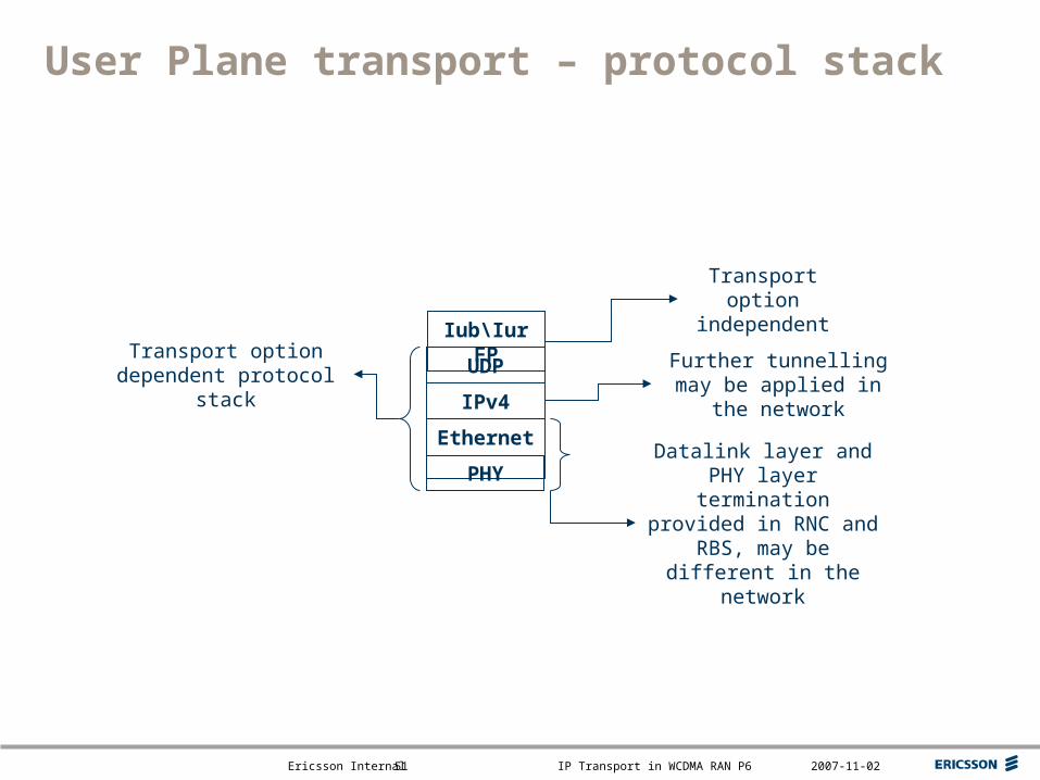
User Plane transport – protocol stack
Iub\Iur FP
UDP
IPv4
Ethernet
PHY
Transport option independent
Datalink layer and PHY layer termination provided in RNC and RBS, may be
different in the network
Further tunnelling may be applied in the network
Transport option dependent protocol stack
Top right corner for field-mark, customer or partner logotypes. See Best practice for example.
Slide title 40 pt
Slide subtitle 24 pt
Text 24 pt
Bullets level 2-520 pt
Ericsson Internal IP Transport in WCDMA RAN P6 2007-11-0252
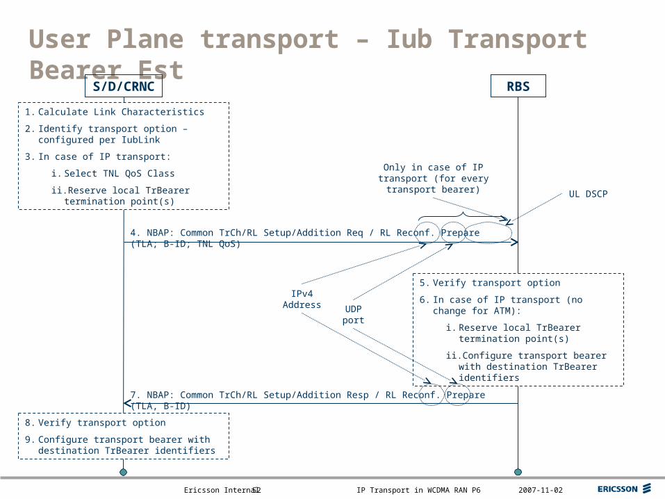
7. NBAP: Common TrCh/RL Setup/Addition Resp / RL Reconf. Prepare (TLA, B-ID)
User Plane transport – Iub Transport Bearer Est
RBS
4. NBAP: Common TrCh/RL Setup/Addition Req / RL Reconf. Prepare (TLA; B-ID; TNL QoS)
S/D/CRNC
1. Calculate Link Characteristics
2. Identify transport option – configured per IubLink
3. In case of IP transport:
i. Select TNL QoS Class
ii. Reserve local TrBearer termination point(s)
Only in case of IP transport (for every transport bearer)
5. Verify transport option
6. In case of IP transport (no change for ATM):
i. Reserve local TrBearer termination point(s)
ii. Configure transport bearer with destination TrBearer identifiers
8. Verify transport option
9. Configure transport bearer with destination TrBearer identifiers
IPv4 Address
UDP port
UL DSCP
Top right corner for field-mark, customer or partner logotypes. See Best practice for example.
Slide title 40 pt
Slide subtitle 24 pt
Text 24 pt
Bullets level 2-520 pt
Ericsson Internal IP Transport in WCDMA RAN P6 2007-11-0253
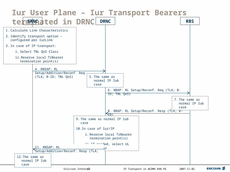
6. NBAP: RL Setup/Reconf. Req (TLA; B-ID; TNL QoS)
Iur User Plane – Iur Transport Bearers terminated in DRNC
8. NBAP: RL Setup/Reconf. Resp (TLA, B-ID)
RBS
4. RNSAP: RL Setup/Addition/Reconf. Req (TLA; B-ID; TNL QoS)
SRNC DRNC
1. Calculate Link Characteristics
2. Identify transport option – configured per IurLink
3. In case of IP transport:
i. Select TNL QoS Class
ii. Reserve local TrBearer termination point(s)
5. The same as normal IP Iub case
7. The same as normal IP Iub case
9. The same as normal IP Iub case
10.In case of Iur/IP
i. Reserve local TrBearer termination point(s)
ii. If needed, select UL QoS Class
11. RNSAP: RL Setup/Addition/Reconf. Resp (TLA; B-ID)
12.The same as normal IP Iub case
Top right corner for field-mark, customer or partner logotypes. See Best practice for example.
Slide title 40 pt
Slide subtitle 24 pt
Text 24 pt
Bullets level 2-520 pt
Ericsson Internal IP Transport in WCDMA RAN P6 2007-11-0254
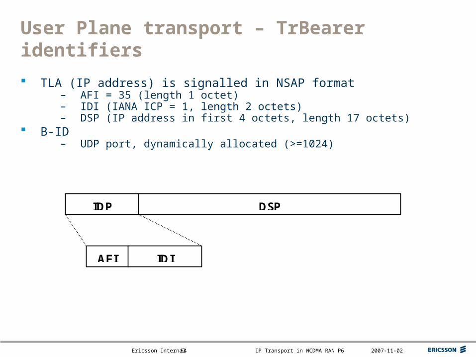
User Plane transport – TrBearer identifiers
TLA (IP address) is signalled in NSAP format– AFI = 35 (length 1 octet)– IDI (IANA ICP = 1, length 2 octets)– DSP (IP address in first 4 octets, length 17 octets)
B-ID– UDP port, dynamically allocated (>=1024)
IDP DSP
AFI IDI
Top right corner for field-mark, customer or partner logotypes. See Best practice for example.
Slide title 40 pt
Slide subtitle 24 pt
Text 24 pt
Bullets level 2-520 pt
Ericsson Internal IP Transport in WCDMA RAN P6 2007-11-0255
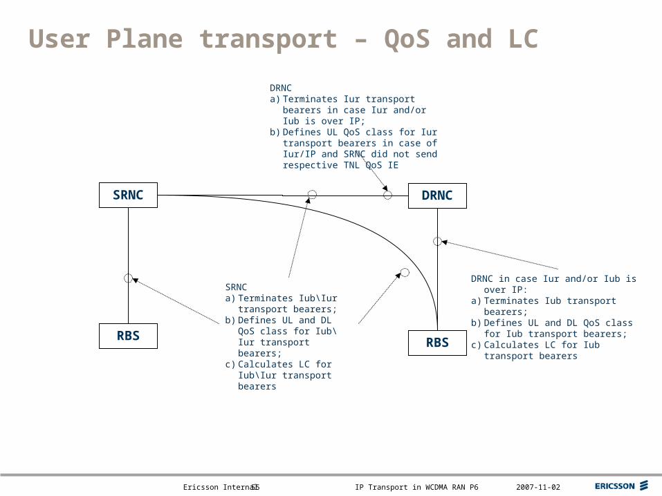
User Plane transport – QoS and LC
SRNC DRNC
RBS RBS
SRNCa) Terminates Iub\Iur transport
bearers;b) Defines UL and DL QoS
class for Iub\Iur transport bearers;
c) Calculates LC for Iub\Iur transport bearers
DRNCa) Terminates Iur transport bearers in
case Iur and/or Iub is over IP;b) Defines UL QoS class for Iur transport
bearers in case of Iur/IP and SRNC did not send respective TNL QoS IE
DRNC in case Iur and/or Iub is over IP:a) Terminates Iub transport bearers;b) Defines UL and DL QoS class for Iub
transport bearers;c) Calculates LC for Iub transport bearers
Top right corner for field-mark, customer or partner logotypes. See Best practice for example.
Slide title 40 pt
Slide subtitle 24 pt
Text 24 pt
Bullets level 2-520 pt
Ericsson Internal IP Transport in WCDMA RAN P6 2007-11-0256
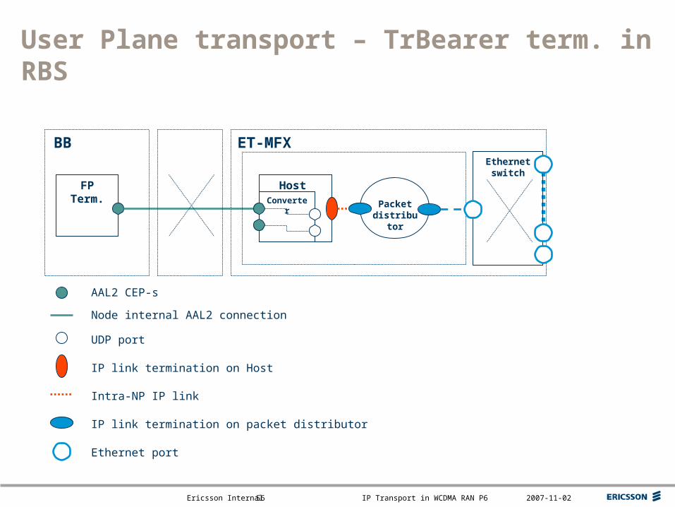
User Plane transport – TrBearer term. in RBS
Converter Packet distributor
ET-MFXBB
FP Term.
AAL2 CEP-s
IP link termination on Host
Node internal AAL2 connection
Intra-NP IP link
IP link termination on packet distributor
Ethernet port
Host
UDP port
Ethernet switch
Top right corner for field-mark, customer or partner logotypes. See Best practice for example.
Slide title 40 pt
Slide subtitle 24 pt
Text 24 pt
Bullets level 2-520 pt
Ericsson Internal IP Transport in WCDMA RAN P6 2007-11-0257
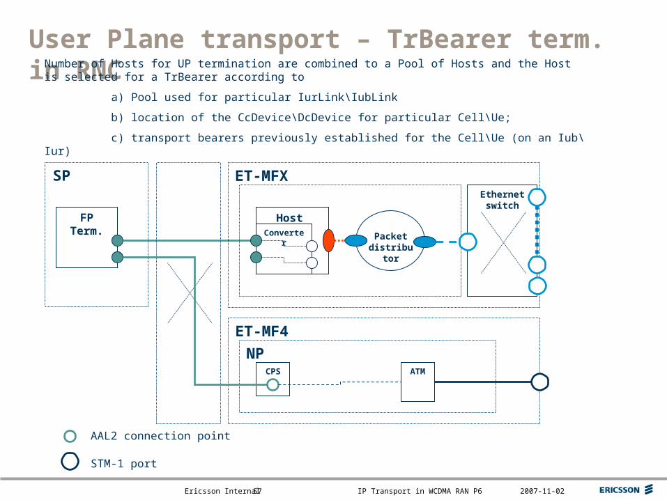
User Plane transport – TrBearer term. in RNC
SP
FP Term.
CPS
ET-MF4
NPATM
AAL2 connection point
STM-1 port
Converter Packet distributor
ET-MFX
Host
Ethernet switch
Number of Hosts for UP termination are combined to a Pool of Hosts and the Host is selected for a TrBearer according to
a) Pool used for particular IurLink\IubLink
b) location of the CcDevice\DcDevice for particular Cell\Ue;
c) transport bearers previously established for the Cell\Ue (on an Iub\Iur)
Top right corner for field-mark, customer or partner logotypes. See Best practice for example.
Slide title 40 pt
Slide subtitle 24 pt
Text 24 pt
Bullets level 2-520 pt
Ericsson Internal IP Transport in WCDMA RAN P6 2007-11-0258
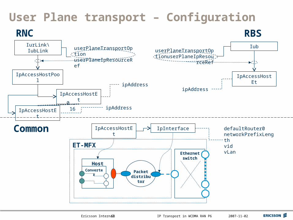
User Plane transport – Configuration
Converter Packet distributor
ET-MFX
Host
Ethernet switch
IpAccessHostEt IpInterface
IpAccessHostEt
IpAccessHostEt
IpAccessHostPool
IurLink\IubLink
0..16
userPlaneTransportOptionuserPlaneIpResourceRef
RNC RBS
IpAccessHostEt
IubuserPlaneTransportOption
userPlaneIpResourceRef
Common defaultRouter0networkPrefixLengthvidvLan
ipAddressipAddress
ipAddress
Top right corner for field-mark, customer or partner logotypes. See Best practice for example.
Slide title 40 pt
Slide subtitle 24 pt
Text 24 pt
Bullets level 2-520 pt
Ericsson Internal IP Transport in WCDMA RAN P6 2007-11-0259
TNL QoS
Overview Configuration
Top right corner for field-mark, customer or partner logotypes. See Best practice for example.
Slide title 40 pt
Slide subtitle 24 pt
Text 24 pt
Bullets level 2-520 pt
Ericsson Internal IP Transport in WCDMA RAN P6 2007-11-0260
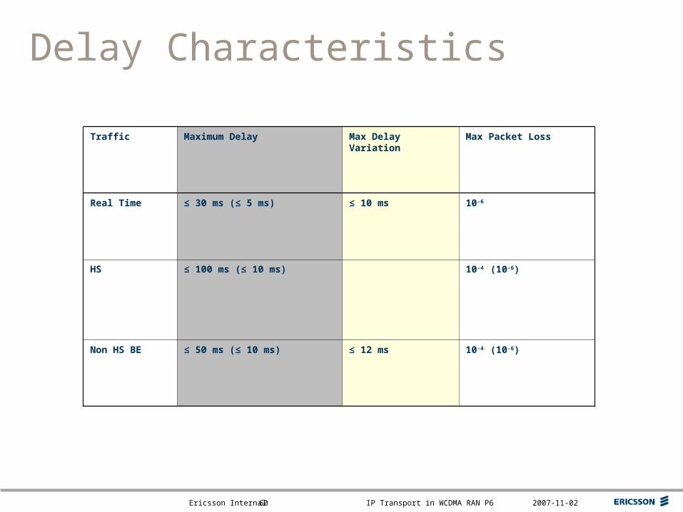
Traffic Maximum Delay Max Delay Variation Max Packet Loss
Real Time ≤ 30 ms (≤ 5 ms) ≤ 10 ms 10-6
HS ≤ 100 ms (≤ 10 ms) 10-4 (10-6)
Non HS BE ≤ 50 ms (≤ 10 ms) ≤ 12 ms 10-4 (10-6)
Delay Characteristics
Top right corner for field-mark, customer or partner logotypes. See Best practice for example.
Slide title 40 pt
Slide subtitle 24 pt
Text 24 pt
Bullets level 2-520 pt
Ericsson Internal IP Transport in WCDMA RAN P6 2007-11-0261
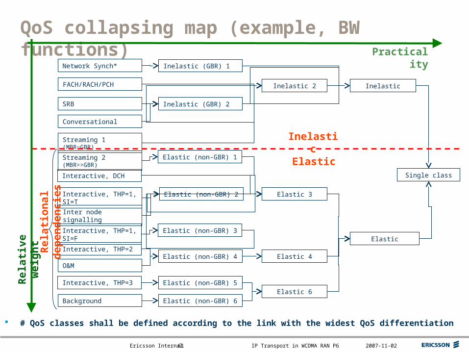
QoS collapsing map (example, BW functions)
FACH/RACH/PCH
SRB
Streaming 1 (MBR~GBR)
Conversational
Streaming 2 (MBR>>GBR)
Interactive, THP=1, SI=T
Inter node signalling
Network Synch*
Interactive, THP=1, SI=F
Interactive, THP=2
Interactive, THP=3
O&M
Background
Elastic (non-GBR) 2
Elastic (non-GBR) 3
Elastic (non-GBR) 4
Elastic (non-GBR) 5
Elastic (non-GBR) 6
Inelastic (GBR) 2
Inelastic (GBR) 1
Elastic (non-GBR) 1
Elastic 3
Elastic 4
Elastic 6
Inelastic 2
Elastic
Inelastic
Single classInteractive, DCH
Elastic
Inelastic
PracticalityR
elat
ion
al d
epen
den
cies
# QoS classes shall be defined according to the link with the widest QoS differentiation
Rel
ativ
e w
eig
ht
Top right corner for field-mark, customer or partner logotypes. See Best practice for example.
Slide title 40 pt
Slide subtitle 24 pt
Text 24 pt
Bullets level 2-520 pt
Ericsson Internal IP Transport in WCDMA RAN P6 2007-11-0262
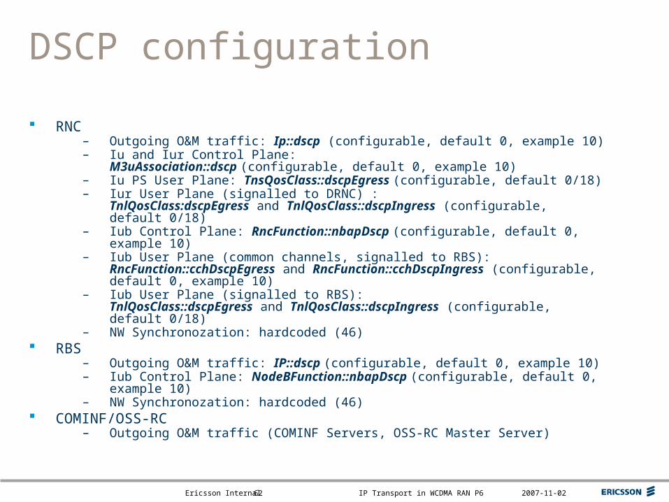
DSCP configuration
RNC– Outgoing O&M traffic: Ip::dscp (configurable, default 0, example 10)– Iu and Iur Control Plane:
M3uAssociation::dscp (configurable, default 0, example 10)– Iu PS User Plane: TnsQosClass::dscpEgress (configurable, default 0/18)– Iur User Plane (signalled to DRNC) :
TnlQosClass:dscpEgress and TnlQosClass::dscpIngress (configurable, default 0/18)
– Iub Control Plane: RncFunction::nbapDscp (configurable, default 0, example 10)– Iub User Plane (common channels, signalled to RBS):
RncFunction::cchDscpEgress and RncFunction::cchDscpIngress (configurable, default 0, example 10)
– Iub User Plane (signalled to RBS):TnlQosClass::dscpEgress and TnlQosClass::dscpIngress (configurable, default 0/18)
– NW Synchronozation: hardcoded (46) RBS
– Outgoing O&M traffic: IP::dscp (configurable, default 0, example 10)– Iub Control Plane: NodeBFunction::nbapDscp (configurable, default 0, example 10)– NW Synchronozation: hardcoded (46)
COMINF/OSS-RC– Outgoing O&M traffic (COMINF Servers, OSS-RC Master Server)
Top right corner for field-mark, customer or partner logotypes. See Best practice for example.
Slide title 40 pt
Slide subtitle 24 pt
Text 24 pt
Bullets level 2-520 pt
Ericsson Internal IP Transport in WCDMA RAN P6 2007-11-0263
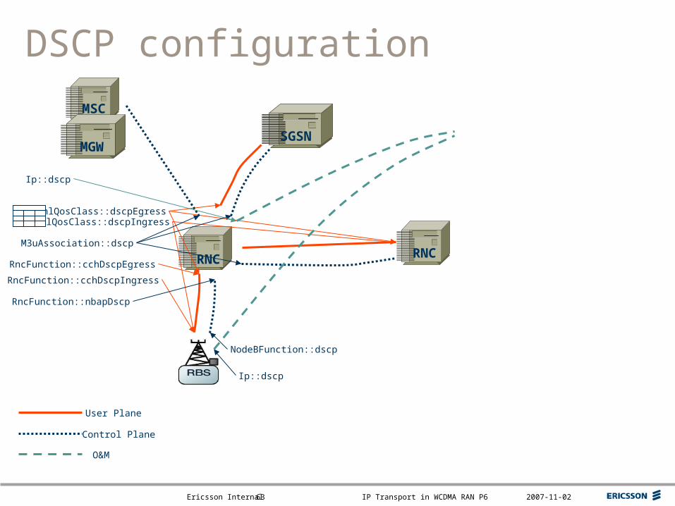
MSC
DSCP configuration
RNC
SGSNMGW
RNC
User Plane
Control Plane
O&M
TnlQosClass::dscpIngressTnlQosClass::dscpEgress
RncFunction::cchDscpEgress
RncFunction::cchDscpIngress
NodeBFunction::dscp
RncFunction::nbapDscp
M3uAssociation::dscp
Ip::dscp
Ip::dscp
Top right corner for field-mark, customer or partner logotypes. See Best practice for example.
Slide title 40 pt
Slide subtitle 24 pt
Text 24 pt
Bullets level 2-520 pt
Ericsson Internal IP Transport in WCDMA RAN P6 2007-11-0264
Node Synchronisation
Overview Signalling Algorithm principles
Top right corner for field-mark, customer or partner logotypes. See Best practice for example.
Slide title 40 pt
Slide subtitle 24 pt
Text 24 pt
Bullets level 2-520 pt
Ericsson Internal IP Transport in WCDMA RAN P6 2007-11-0265
Node Synchronisation – Overview
Why were the principles changed– Provide common solution independent of Iub transport option
What was changed– Common TrCh setup order in relation to node synchronisation– Node synchronisation algorithm
Handle increased delay variation– Input to (A/E-)DCH and MBMS/FACH frame synchronisation
Improved estimate of transfer delay
Top right corner for field-mark, customer or partner logotypes. See Best practice for example.
Slide title 40 pt
Slide subtitle 24 pt
Text 24 pt
Bullets level 2-520 pt
Ericsson Internal IP Transport in WCDMA RAN P6 2007-11-0266
4. NBAP: Common Transport Channel Setup Response
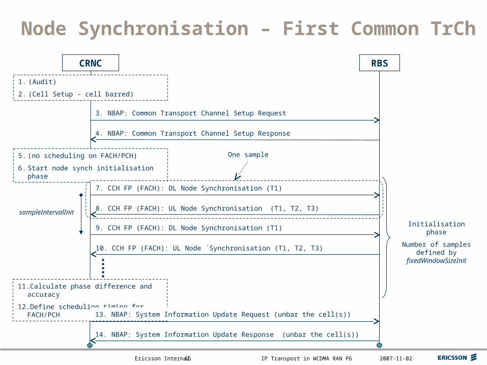
Node Synchronisation – First Common TrCh
3. NBAP: Common Transport Channel Setup Request
CRNC
1. (Audit)
2. (Cell Setup – cell barred)
5. (no scheduling on FACH/PCH)
6. Start node synch initialisation phase
One sample
8. CCH FP (FACH): UL Node Synchronisation (T1, T2, T3)
7. CCH FP (FACH): DL Node Synchronisation (T1)
10. CCH FP (FACH): UL Node ´Synchronisation (T1, T2, T3)
9. CCH FP (FACH): DL Node Synchronisation (T1)
RBS
Initialisation phase
Number of samples defined by
fixedWindowSizeInit
sampleIntervalInit
11.Calculate phase difference and accuracy
12.Define scheduling timing for FACH/PCH
14. NBAP: System Information Update Response (unbar the cell(s))
13. NBAP: System Information Update Request (unbar the cell(s))
Top right corner for field-mark, customer or partner logotypes. See Best practice for example.
Slide title 40 pt
Slide subtitle 24 pt
Text 24 pt
Bullets level 2-520 pt
Ericsson Internal IP Transport in WCDMA RAN P6 2007-11-0267
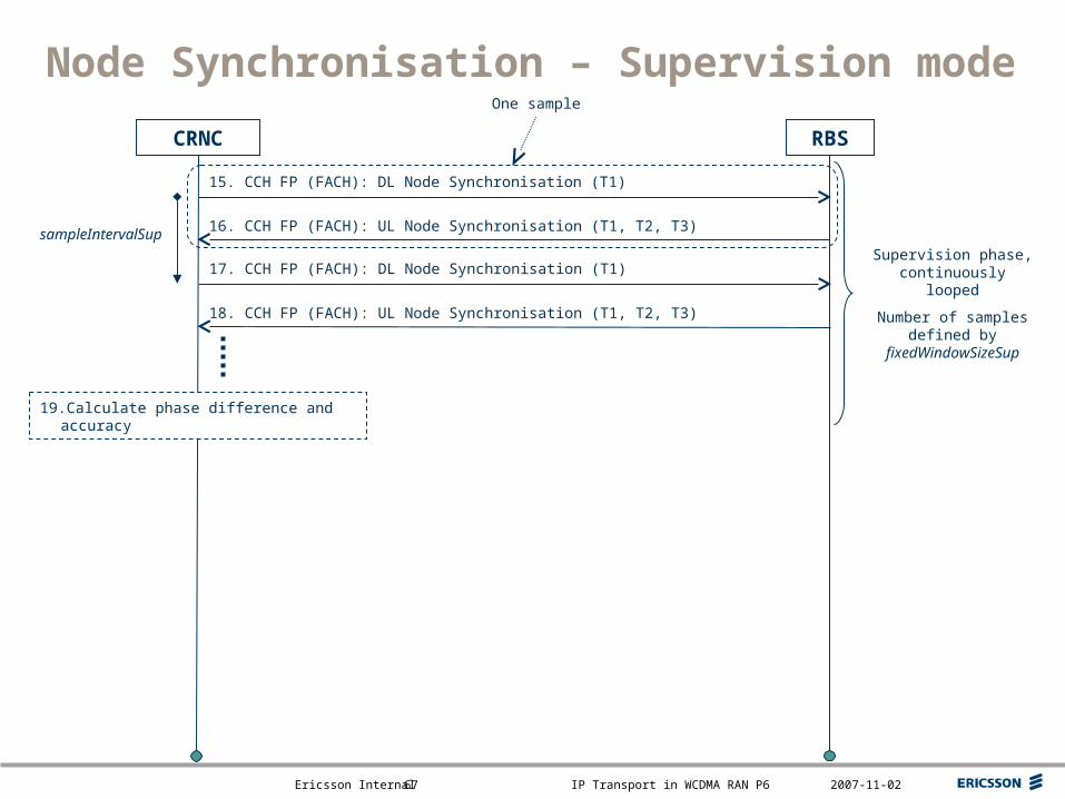
Node Synchronisation – Supervision mode
CRNC
One sample
16. CCH FP (FACH): UL Node Synchronisation (T1, T2, T3)
15. CCH FP (FACH): DL Node Synchronisation (T1)
18. CCH FP (FACH): UL Node Synchronisation (T1, T2, T3)
17. CCH FP (FACH): DL Node Synchronisation (T1)
RBS
Supervision phase, continuously looped
Number of samples defined by
fixedWindowSizeSup
sampleIntervalSup
19.Calculate phase difference and accuracy
Top right corner for field-mark, customer or partner logotypes. See Best practice for example.
Slide title 40 pt
Slide subtitle 24 pt
Text 24 pt
Bullets level 2-520 pt
Ericsson Internal IP Transport in WCDMA RAN P6 2007-11-0268
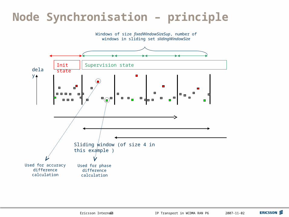
Node Synchronisation – principle
delay
Sliding window (of size 4 in this example )
Windows of size fixedWindowSizeSup, number of windows in sliding set slidingWindowSize
Init state Supervision state
Used for phase difference calculation
Used for accuracy difference calculation

Top right corner for field-mark, customer or partner logotypes. See Best practice for example.
Slide title 40 pt
Slide subtitle 24 pt
Text 24 pt
Bullets level 2-520 pt
Ericsson Internal IP Transport in WCDMA RAN P6 2007-11-0270