The New Comprehensive Stryker®
VariAx™ Distal RadiusLocking Plate System
• Anatomical & Universal Volar Plates• Dorsal Plates• Fragment Specific Plates
Operative Technique

Introduction
The NEW VariAx™ Distal Radius Plating
System represents the Next Generation
of Bone Fixation for virtually all of your
Distal Radius Fracture Needs.
System Features
• Complete Plating System
Providing Anatomical Volar and Dorsal,
Universal Volar and Fragment Specific
Solutions, even for the most complex
distal radius fracture.
• Fixed Angle Drill Guide
Assures placement of screws &
pegs in a pre-determined angle.
• Polyaxial Drill Guide
Allows locking with an additional
angulation of ±15 degrees in any hole
on the plate.
• New Anatomical Volar Plate
Encourages articular support with
Locking screws & pegs, provides optimal
buttressing to the Distal Radial Ulnar
Joint (DRUJ) and stable fixation of
radial styloid fragments with two screws.
• Full range of 2.0mm to 2.7mmLocking
and Non-Locking screws & pegs
Offering intraoperative solutions for
different fracture fixation requirements.
• Anodization Type II
Increases the strength of all VariAx™
Distal Radius Locking Plates and
may reduce the incidence of
tissue adherence.
SmartLock Locking Technology
• Patented SmartLock Locking
Technology
Encourages “locked” screw to plate
interface due to combination of
Grade II – Ti Plates and
Grade V – Ti Screws & Pegs
• SmartLock Locking Screws & Pegs
Designed with threads on the underside
of the screw head, which upon
insertion engage the circular “lip”
within any hole on the plate.
• Unique one-step Locking
Achieved by simply inserting a
Locking Screw or Peg within the
polyaxial locking range of ±15 degrees,
without the need for further steps.
Cross-Pin Screw Head Design
• Optimal axial stability
• Improved friction fit
• Easy screw pick up
2
-15° +15°
This operative technique was developedwith Richard Rogachefsky, MD.

3
Overview
Plate Options
Screw/Peg Options
2.0mmSmoothLocking
2.3mmLocking
2.7mmLocking
2.7mmPartialThreadLocking
2.3mmNon-
Locking
2.7mmNon-
Locking
2.7mmPartialThread
Non-Locking
AnatomicalVolar Plates
Left
Right
UniversalVolar Plates
DorsalPlates
RadialColumnPlates
UlnarColumnPlates

4
Operative Technique
Fixed Angle Drill GuideThis drill guide will ensure a pre-fixed
angle for placement of screw options in
every case. It does not allow the flexibility
of choosing an angle. It is designed to fit
into the pre-tilted lips within the holes on
the plate by simply pressing the drill
guide into the hole.
Note: In order to prevent toggle, this drill
guide is designed to fit very tightly into
the holes of the plate.When utilizing this
instrument follow the same trajectory
of the pre-tilted lips to facilitate its
placement. This will be important when
approaching the radial styloid screw holes.
SmartLock PolyaxialDrill GuideThis dual guide allows for ±15 degrees
of custom angulation of screws and pegs
and may be used for more complex
fractures. A lip on the drill sleeve will
engage and allow toggling in the hole.
The range in which the drill guide
toggles will create a 30 degree cone with
every angle in this cone will be a locking
position.
This may allow for the surgeon to aim
where the screw/peg should be placed.
Note: Fully engage the drill guide
into the hole before aiming the drill in
the desired direction.
2.3mm Drill Guide/K-Wire GuideThe K-Wire guide provides an option to
assess potential screw positions by
inserting a 1.1mm K-Wire prior to any
drilling or screw insertion. By using the
same technique, this K-Wire guide offers
the same 30 degree locking cone as the
SmartLock Polyaxial Drill Guide.
It may also be utilized to provide
temporary fixation to smaller fragments,
while capturing these fragments with
adjacent locking screws.
The 2.3mm drill guide can be used
as an overdrill to lag 2.3mm screws if
compression is desired or as a pilot
hole for 2.7mm screws in dense bone.
This drill guide can only be used in a
fixed angle.
Pre-determined Screw Pattern
18° Distal12° Lateral
15° Distal15° Lateral 5° Proximal
12° Proximal0°
5° Proximal0°
18° Distal12° Lateral
0°10° Proximal
5° Proximal
15° Distal15° Lateral

1a 1b
5
Step 1An incision is made approximately 8cm
long just radial to the FCR tendon. If
more exposure is necessary, the incision
can be extended radially at 45 degrees
along the wrist flexion creases.
Step 2The FCR tendon is retracted ulnarly and
dissection is carried down through the
floor of the FCR sheath. This exposes the
FCR muscle belly, which may be
retracted ulnarly as well.
Step 3The Pronator Quadratus is identified
and dissected in its entirety off of the
volar surface of the radius as an ulnarly
based flap.
Step 4The insertion of the Brachioradialis
may be released.
Step 5The fracture is visualized and reduced.
Step 6The use of external traction, and/or the
use of K-Wires for temporary fixation
could be helpful. If necessary, bone graft
materials may be used as an adjunct to
the plate to provide an optimal bone void
filler. The use of AP/Lateral fluoroscopy
is helpful to determine correct fracture
reduction and plate position.
2
3-4
5-6
Operative TechniqueAnatomical Volar Plates

6
Operative TechniqueAnatomical Volar Plate
Step 7Choose the appropriate implant
according to patient anatomy and
fracture pattern.
Step 8The plate should be placed slightly below the
distal edge of the radius to support the volar
articular fracture fragments and also to
avoid inserting screws or pegs into the joint.
Step 9Zebra striped K-Wires and/or Olive K-Wires
can be used for temporary fixation while
evaluating the placement of the plate.
Step 10The first pilot hole should be drilled in
the oval gliding hole using the appropriate
drill guide.
Step 11Use the depth gauge to determine screw
length.
Step 12A non-locking screw is placed in the oval
gliding hole but not completely tightened
to allow adjustment of the plate in distal or
proximal directions.
Step 13After confirmation of the correct
positioning of the anatomic volar plate by
use of fluoroscopy, tighten the first screw.
7
8-9
10-11
12-13
Left Right

7
Step 14Once the position of the plate has been
determined, it is time to decide which
drill guide to use based upon preference
and/or fracture pattern.
Step 15Using the desired drill guide, repeat
drilling, measuring and placement of
screws/pegs in the distal holes.
Step 16Place locking or non-locking screws in
the proximal end of the plate.*
*Note: In very dense bone it is
recommended to use the 2.3mm drill
bit in conjunction with the 2.3mm
drill guide for a 2.7mm screw.
Step 17Verify proper placement of screws/pegs
by use of fluoroscopy to ensure that
neither penetrate the joint.
Step 18Close the incision.
14
15-16
17-18
x
Operative TechniqueAnatomical Volar Plate

8
Operative TechniqueUniversal Volar Plate
Step 1An incision is made approximately 8cm
long just radial to the FCR tendon. If
more exposure is necessary, the incision
can be extended radially at 45 degrees
along the wrist flexion creases.
Step 2The FCR tendon is retracted ulnarly and
dissection is carried down through the
floor of the FCR sheath. This exposes the
FCR muscle belly, which may be
retracted ulnarly as well.
Step 3The Pronator Quadratus is identified
and dissected in its entirety off of the
volar surface of the radius as an ulnarly
based flap.
Step 4The insertion of the Brachioradialis may
be released.
2
3-4
x
1a 1b

Step 7
The plate should be placed slightly below
the distal edge of the distal radius to
avoid inserting screws or pegs into the
joint. The use of AP/Lat fluoroscopy is
helpful to determine correct fracture
reduction and plate position.
Step 8K-Wires can be used for temporary
fixation.
Step 9The first pilot hole should be drilled in
the oval gliding hole using the
appropriate drill guide.
Step 10Measure the depth of the hole to
determine screw length.
Step 11The screw is placed in the oval gliding
hole but not completely tightened to
allow adjustment of the plate in distal or
proximal directions.
9
Step 5The fracture is visualized and reduced.
Step 6The fracture is reduced. The use of
external traction, and/or the use of
K-Wires for temporary fixation could be
helpful.If necessary, bone graft materials
may be used as an adjunct to the plate to
provide an optimal bone void filler.
5-6
7-8
9-11
Operative TechniqueUniversal Volar Plate

10
Operative TechniqueUniversal Volar Plate
Step 12After confirmation of the correct
positioning of the volar plate by use of
fluoroscopy, tighten the first screw.
Step 13Repeat drilling, measuring and placing of
screws/pegs in the distal holes of the
plate. The position and number of screws
applied depends on the type of fracture.
Step 14Place the bone or locking screws in
the proximal end of the plate.
Step 15Verify proper placement of screws and
pegs by use of fluoroscopy to ensure
that neither penetrates the joint.
Step 16Close the incision.
x
x
16
x
12 13
14 15

11
Step 1Longitudinal incision is made just
ulnar to Lister’s tubercle at the distal
radius region.
Step 2Dissection is performed down to
the extensor retinaculum. The third
compartment is opened and the
extensor pollicis longus is
displaced radially.
Step 3The second compartment wrist extensors
are subperiosteally elevated radially and
the fourth compartment is subperiosteally
elevated ulnarly. The dorsal interosseous
nerve might be cut off for pain reduction.
Step 4The fracture is reduced. The use of an
external traction device and/or K-Wires
for temporary fixation may be helpful.
If necessary, bone graft materials may be
used as an adjunct to the plate to provide
an optimal bone void filler.
Step 5If necessary, adapt the plate for correct
anatomical position. Removal of
Tuberculum Listeri might be necessary.
2
3
4-5
Operative TechniqueDorsal Plate
1a 1b
12
Operative TechniqueDorsal Plate
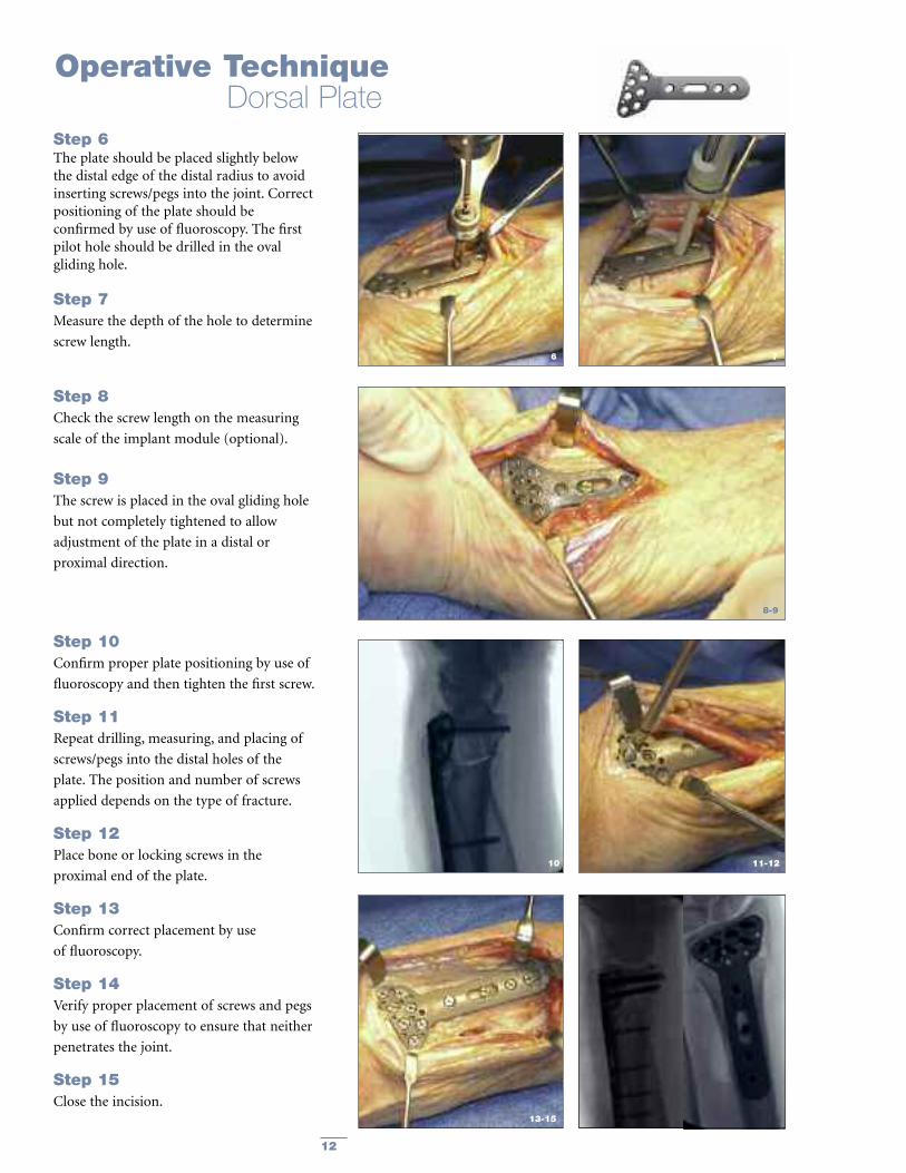
Step 6The plate should be placed slightly belowthe distal edge of the distal radius to avoidinserting screws/pegs into the joint. Correctpositioning of the plate should beconfirmed by use of fluoroscopy. The firstpilot hole should be drilled in the ovalgliding hole.
Step 7Measure the depth of the hole to determine
screw length.
Step 8Check the screw length on the measuring
scale of the implant module (optional).
Step 9The screw is placed in the oval gliding hole
but not completely tightened to allow
adjustment of the plate in a distal or
proximal direction.
Step 10Confirm proper plate positioning by use of
fluoroscopy and then tighten the first screw.
Step 11Repeat drilling, measuring, and placing of
screws/pegs into the distal holes of the
plate. The position and number of screws
applied depends on the type of fracture.
Step 12Place bone or locking screws in the
proximal end of the plate.
Step 13Confirm correct placement by use
of fluoroscopy.
Step 14Verify proper placement of screws and pegs
by use of fluoroscopy to ensure that neither
penetrates the joint.
Step 15Close the incision.
x
8-9
6 7
10 11-12
13-15

13
Step 1Incision is made along the radial column.
Step 2Care must be taken to avoid injury to
dorsal sensory branch of the radial nerve.
Step 3First dorsal compartment is freed from
dorsal to volar to allow plate placement.
Step 4Plate is placed along the radial column.
Step 5Screws or distal K-Wires can be placed
for fixation options.
1-2
3
4
5
Operative TechniqueRadial Column Plate

14
Operative TechniqueRadial Column Plate
Step 6The 3 in 1 K-Wire bender/cutter/inserter
is used to place K-Wires distally.
Step 7It is recommended only one K-Wire be
placed distally at a time in order to make
proper use of the bender/cutter/inserter
instrument.
Step 8After insertion, the tamp and mallet can
be used to further insert the K-Wires.
Step 9K-Wires and screws can be placed in
conjunction for more rigid fixation.
Step 10The incision is closed.
x
8
9-10
6-7 6-7
6-7

15
Ordering InformationVolar Plates
REF Description
54-25384 Anatomical Volar DR Plate
Narrow, Right
54-25374 Anatomical Volar DR Plate
Narrow, Left
54-25386 Anatomical Volar DR Plate
Standard, Right
54-25376 Anatomical Volar DR Plate
Standard, Left
54-25385 Anatomical Volar DR Plate
Narrow, Right, Long
54-25375 Anatomical Volar DR Plate
Narrow, Left, Long
54-25387 Anatomical Volar DR Plate
Standard, Right, Long
54-25377 Anatomical Volar DR Plate
Standard, Left, Long
54-25394 Universal Volar DR Plate
Narrow, Short
54-25396 Universal Volar DR Plate
Standard, Short
54-25398 Universal Volar DR Plate
Wide, Short
54-25395 Universal Volar DR Plate
Narrow, Long
54-25397 Universal Volar DR Plate
Standard, Long
54-25399 Universal Volar DR Plate
Wide, Long
54-25391 Universal Volar DR Plate
Narrow, XLong
54-25392 Universal Volar DR Plate
Standard, XLong
54-25393 Universal Volar DR Plate
Wide, XLong
Dorsal PlatesREF Description
54-25290 Dorsal DR Plate
Standard, Right
54-25291 Dorsal DR Plate
Standard, Left
54-25292 Dorsal DR Plate
Wide, Right
54-25293 Dorsal DR Plate
Wide, Left
54-25294 Dorsal DR Plate
Standard, Right, XLong
54-25295 Dorsal DR Plate
Standard, Left, XLong
54-25296 Dorsal DR Plate
Wide, Right, XLong
54-25297 Dorsal DR Plate
Wide, Left, Xlong
Fragment Specific Plates
REF Description
54-25400 Radial Column Plate
Short
54-25401 Radial Column Plate
Long
54-25402 Ulnar Column Plate
Short, Right
54-25403 Ulnar Column Plate
Short, Left
54-25404 Ulnar Column Plate
Long, Right
54-25405 Ulnar Column Plate
Long, Left
The Variax Distal Radius Plating Systemincorporates plate designs originating fromthe Matrix Distal Radius Plating Systemdeveloped by Stryker in conjunction withRichard Rogachefsky, MD.
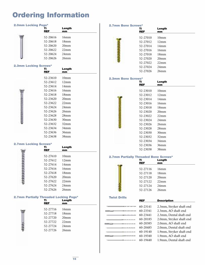
16
Ordering Information2.0mm Locking Pegs*
Ti LengthREF mm
52-20616 16mm52-20618 18mm52-20620 20mm52-20622 22mm52-20624 24mm52-20626 26mm
2.3mm Locking Screws*Ti LengthREF mm
52-23610 10mm52-23612 12mm52-23614 14mm52-23616 16mm52-23618 18mm52-23620 20mm52-23622 22mm52-23624 24mm52-23626 26mm52-23628 28mm52-23630 30mm52-23632 32mm52-23634 34mm52-23636 36mm52-23638 38mm
2.7mm Locking Screws*Ti LengthREF mm
52-27610 10mm52-27612 12mm52-27614 14mm52-27616 16mm52-27618 18mm52-27620 20mm52-27622 22mm52-27624 24mm52-27626 26mm
2.7mm Partially Threaded Locking Pegs*Ti LengthREF mm
52-27716 16mm52-27718 18mm52-27720 20mm52-27722 22mm52-27724 24mm52-27726 26mm
2.7mm Bone Screws*Ti LengthREF mm
52-27010 10mm52-27012 12mm52-27014 14mm52-27016 16mm52-27018 18mm52-27020 20mm52-27022 22mm52-27024 24mm52-27026 26mm
2.3mm Bone Screws*Ti LengthREF mm
52-23010 10mm52-23012 12mm52-23014 14mm52-23016 16mm52-23018 18mm52-23020 20mm52-23022 22mm52-23024 24mm52-23026 26mm52-23028 28mm52-23030 30mm52-23032 32mm52-23034 34mm52-23036 36mm52-23038 38mm
2.7mm Partially Threaded Bone Screws*Ti LengthREF mm
52-27116 16mm52-27118 18mm52-27120 20mm52-27122 22mm52-27124 24mm52-27126 26mm
Twist DrillsREF Description
60-23141 2.3mm, Stryker shaft end60-23341 2.3mm, AO shaft end60-23441 2.3mm, Dental shaft end60-20185 2.0mm, Stryker shaft end60-20385 2.0mm, AO shaft end60-20485 2.0mm, Dental shaft end60-19140 1.9mm, Stryker shaft end60-19340 1.9mm, AO shaft end60-19440 1.9mm, Dental shaft end

17
Ordering InformationInstrumentation
REF Description
62-20290 Screwdriver RatchetingHandle
62-27007 Cross-Pin Blade2.3mm/2.7mm
56-01250 Polyaxial Drill Guide2.3mm/2.7mm
56-01255 Fixed Angle Drill Guide2.3mm/2.7mm
56-01260 2.3mm Overdrill andK-Wire Guide
62-00016 Depth Measuring Gauge
64-20117 Plate Bending Pliers
64-20118 K-Wire Bending Pliers
64-20129 Forceps w/Grasping Lips
Bone Reduction InstrumentsREF Description
07-30600 Lobster Bone HoldingForceps
07-30111 Lewin Bone HoldingForceps, Sharp Tip
07-10006 Elevator, Double sided,Narrow &Wide, Hohmanns
07-10021 Elevator, Double sided,Strong & Light Curved
07-10175 Bone Hook
43-09830 Mallet (250g)
64-00011 Tamp
K-WiresREF Description
56-40281 K-Wire with Olive Stop*
07-40281 K-Wire, 1.1x160mm**
Note: The following drills may be ordered sterile by replacing “60-” by “91-” in their respective Cat. Nr.: 60- 20185 / 20385 / 19340 / 19440.
*Order Quantity: Packages of 5. **Order Quantity: Packages of 10.
Implant ModuleREF Description
29-27001 VariAx™ Distal RadiusLocking Implant Module,double-sized
29-27002 Inlay for Anatomical VolarDistal Radius Plates
29-27003 Inlay for Universal VolarDistal Radius Plates
Sterilizing ContainerREF Description
29-13012 VariAx™ Lid for SterilizingContainer
29-13013 Sterilizing Container, Half-size, w/o VariAx™ Lid
29-13114 VariAx™ Distal RadiusPlating Instrument Tray
29-13024 VariAx™ Distal RadiusBone Reduction Tray
Optional ItemsREF Description
62-00017 Depth Measuring Gauge(Aluminum, UDR Version)
50-23501 Marker - Locking Screws2.3mm
50-27500 Marker - Locking Screws2.7mm
50-20501 Marker - Locking Pegs2.0mm
50-23001 Marker - Bone Screws2.3mm
50-27000 Marker - Bone Screws2.7mm
50-27001 Marker - PT Bone Screws2.7mm
50-27501 Marker - PT Locking Pegs2.7mm
50-23502 Marker - 2.3mm

18
Complementary Products
KnifeLight
Now Stryker Traumaoffers you a widevariety of solutionsfor the treatmentof all your Hand &Upper ExtremityInjuries.
T2® Humeral Nail
TwinFix™
Hoffmann® II Micro Lengthener Hoffmann® II Compact™ MRI
AxSOS™ Proximal Humeral Plate Asnis™ III 4.0 Cannulated Screws T2® Proximal Humeral Nail
Profyle Modular

19
Notes

A surgeon must always rely on his or her own professional clinical judgment when deciding whether to use a particularproduct when treating a particular patient. Stryker does not dispense medical advice and recommends that surgeons betrained in the use of any particular product before using it in surgery.
The information presented is intended to demonstrate the breadth of Stryker product offerings. A surgeon must always referto the package insert, product label and/or instructions for use before using any Stryker product. Products may not beavailable in all markets because product availability is subject to the regulatory and/or medical practices in individualmarkets. Please contact your Stryker representative if you have questions about the availability of Stryker products in yourarea.
Stryker Corporation or its divisions or other corporate affiliated entities own, use or have applied for the followingtrademarks or service marks: Stryker, Variax. All other trademarks are trademarks of their respective owners or holders.
Literature Number: LVX-OT rev.1MS/GS 1M 1/09
Copyright © 2009 StrykerPrinted in USA
Joint Replacements
Trauma, Extremities & Deformities
Craniomaxillofacial
Spine
Biologics
Surgical Products
Neuro & ENT
Interventional Pain
Navigation
Endoscopy
Communications
Imaging
Patient Handling Equipment
EMS Equipment
325 Corporate DriveMahwah, NJ 07430t: 201 831 5000
www.stryker.com